

Page 1

User’s Guide
NXC Series
Wireless LAN Controller
Default Login Details
LAN IP Address https://192.168.1.1
User Name admin
Password 1234
Version 5.30 Edition 1, 08/2018
Copyright © 2018 Zyxel Communications Corporation
Page 2

IMPORTANT!
READ CAREFULLY BEFORE USE.
KEEP THIS GUIDE FOR FUTURE REFERENCE.
This is a User’s Guide for a series of products. Not all products support all firmware features. Screenshots
and graphics in this book may differ slightly from your product due to differences in your product
firmware or your computer operating system. Every effort has been made to ensure that the information
in this manual is accurate.
Related Documentation
• Quick Start Guide
The Quick Start Guide is designed to show you how to make the NXC hardware connections and
access the Web Configurator.
• CLI Reference Guide
The CLI Reference Guide explains how to use the Command-Line Interface (CLI) and CLI commands
to configure the NXC.
Note: It is recommended you use the Web Configurator to configure the NXC.
• Web Configurator Online Help
Click the help icon in any screen for help in configuring that screen and supplementary information.
• More Information
Go to support.zyxel.com to find other information on the NXC
.
NXC Series User’s Guide
2
Page 3
Document Conventions
Warnings and Notes
These are how warnings and notes are shown in this guide.
Warnings tell you about things that could harm you or your device.
Note: Notes tell you other important information (for example, other things you may need to
configure or helpful tips) or recommendations.
Syntax Conventions
• All models in this series may be referred to as the “NXC” in this guide.
• Product labels, screen names, field labels and field choices are all in bold font.
• A right angle bracket ( > ) within a screen name denotes a mouse click. For example, Configuration >
Network > Interface means you first click Configuration in the navigation panel, then the Network sub
menu and finally the Interface tab to get to that screen.
Icons Used in Figures
Figures in this guide may use the following generic icons. The NXC icon is not an exact representation of
your device.
NXC AP Router Switch
Internet Server Desktop Laptop
NXC Series User’s Guide
3
Page 4

Contents Overview
Contents Overview
User’s Guide ..................................................................................................................................... 17
Introduction ........................................................................................................................................... 18
Hardware Installation and Connection ............................................................................................. 24
The Web Configurator ......................................................................................................................... 30
Setup Wizard ......................................................................................................................................... 44
Technical Reference ....................................................................................................................... 54
Dashboard ............................................................................................................................................ 55
Monitor ................................................................................................................................................... 67
Registration .......................................................................................................................................... 108
Wireless ................................................................................................................................................. 111
Interfaces ............................................................................................................................................. 137
Policy and Static Routes .................................................................................................................... 167
Zones .................................................................................................................................................... 176
NAT ....................................................................................................................................................... 179
ALG ....................................................................................................................................................... 186
IP/MAC Binding ................................................................................................................................... 188
Captive Portal ..................................................................................................................................... 193
RTLS ....................................................................................................................................................... 216
Firewall ................................................................................................................................................. 219
User/Group .......................................................................................................................................... 227
AP Profile .............................................................................................................................................. 246
MON Profile ......................................................................................................................................... 266
ZyMesh Profile ...................................................................................................................................... 271
Addresses ............................................................................................................................................ 275
Services ................................................................................................................................................ 280
Schedules ............................................................................................................................................ 285
AAA Server .......................................................................................................................................... 289
Authentication Method ..................................................................................................................... 300
Certificates .......................................................................................................................................... 303
DHCPv6 ................................................................................................................................................ 318
System .................................................................................................................................................. 320
Log and Report ................................................................................................................................... 362
File Manager ....................................................................................................................................... 377
Diagnostics .......................................................................................................................................... 388
Packet Flow Explore ........................................................................................................................... 402
Reboot ................................................................................................................................................. 408
Shutdown ............................................................................................................................................. 409
NXC Series User’s Guide
4
Page 5

Contents Overview
Troubleshooting .................................................................................................................................. 410
NXC Series User’s Guide
5
Page 6

Table of Contents
Table of Contents
Document Conventions ..................................................................................................................... 3
Contents Overview ............................................................................................................................ 4
Table of Contents................................................................................................................................ 6
Part I: User’s Guide.......................................................................................... 17
Chapter 1
Introduction....................................................................................................................................... 18
1.1 Overview ......................................................................................................................................... 18
1.2 Zones, Interfaces, and Physical Ports ........................................................................................... 18
1.2.1 Interface Types ...................................................................................................................... 19
1.2.2 Interface and Zone Configuration ...................................................................................... 19
1.3 Applications .................................................................................................................................... 20
1.3.1 AP Management .................................................................................................................. 20
1.3.2 Wireless Security .................................................................................................................... 20
1.3.3 Captive Portal ....................................................................................................................... 20
1.3.4 Load Balancing ..................................................................................................................... 21
1.3.5 Dynamic Channel Selection ................................................................................................21
1.3.6 User-Aware Access Control ................................................................................................. 21
1.4 Management Overview ................................................................................................................ 22
1.5 Object-based Configuration ........................................................................................................ 22
1.6 Starting and Stopping the NXC .................................................................................................... 23
Chapter 2
Hardware Installation and Connection .......................................................................................... 24
2.1 Rack-mounted Installation ............................................................................................................ 24
2.1.1 Rack-Mounted Installation Procedure ............................................................................... 24
2.2 Front Panel ....................................................................................................................................... 25
2.2.1 NXC2500 ................................................................................................................................. 25
2.2.2 NXC5500 ................................................................................................................................. 25
2.2.3 Front Panel LEDs .................................................................................................................... 27
2.3 Rear Panel ....................................................................................................................................... 28
Chapter 3
The Web Configurator....................................................................................................................... 30
3.1 Overview ......................................................................................................................................... 30
NXC Series User’s Guide
6
Page 7

Table of Contents
3.2 Access .............................................................................................................................................. 30
3.3 The Main Screen ............................................................................................................................. 31
3.3.1 Title Bar ................................................................................................................................... 32
3.3.2 Navigation Panel .................................................................................................................. 35
3.3.3 Warning Messages ................................................................................................................ 40
3.3.4 Tables and Lists ...................................................................................................................... 40
Chapter 4
Setup Wizard...................................................................................................................................... 44
4.1 Accessing the Wizard ..................................................................................................................... 44
4.2 Using the Wizard ............................................................................................................................. 44
4.2.1 Step 1 Password and Time Settings ..................................................................................... 44
4.2.2 Step 2 Uplink Connection and Management VLAN ....................................................... 45
4.2.3 Step 3 VLAN Settings ............................................................................................................. 46
4.2.4 Step 4 SSID ............................................................................................................................. 49
4.2.5 Step 5 Radio ......................................................................................................................... 51
4.2.6 Summary ............................................................................................................................... 52
Part II: Technical Reference........................................................................... 54
Chapter 5
Dashboard......................................................................................................................................... 55
5.1 Overview ......................................................................................................................................... 55
5.1.1 What You Can Do in this Chapter ....................................................................................... 55
5.2 Dashboard ...................................................................................................................................... 56
5.2.1 CPU Usage ............................................................................................................................. 60
5.2.2 Memory Usage ...................................................................................................................... 60
5.2.3 Session Usage ........................................................................................................................ 61
5.2.4 DHCP Table ............................................................................................................................ 61
5.2.5 Number of Login Users .......................................................................................................... 62
5.2.6 AP Status ................................................................................................................................ 63
5.2.7 Station Traffic ......................................................................................................................... 65
Chapter 6
Monitor............................................................................................................................................... 67
6.1 Overview ......................................................................................................................................... 67
6.1.1 What You Can Do in this Chapter ....................................................................................... 67
6.2 What You Need to Know ............................................................................................................... 68
6.3 Port Statistics ................................................................................................................................... 69
6.3.1 Port Statistics Graph ............................................................................................................. 70
6.4 Interface Status ............................................................................................................................... 71
NXC Series User’s Guide
7
Page 8

Table of Contents
6.5 Traffic Statistics ................................................................................................................................ 73
6.6 Session Monitor .............................................................................................................................. 76
6.7 IP/MAC Binding Monitor ................................................................................................................ 78
6.8 Login Users ...................................................................................................................................... 79
6.8.1 Dynamic Guest .................................................................................................................... 80
6.8.2 Trusted MAC Address List ..................................................................................................... 81
6.9 USB Storage .................................................................................................................................... 82
6.10 Ethernet Neighbor ....................................................................................................................... 83
6.11 AP List ............................................................................................................................................ 84
6.11.1 Station Count of AP ........................................................................................................... 87
6.11.2 Config AP ............................................................................................................................ 89
6.12 Radio List ....................................................................................................................................... 95
6.12.1 AP Mode Radio Information .............................................................................................. 96
6.13 ZyMesh Link Info ............................................................................................................................ 98
6.14 SSID Info ......................................................................................................................................... 99
6.15 Station List ................................................................................................................................... 100
6.16 Detected Device ....................................................................................................................... 101
6.17 View Log ...................................................................................................................................... 103
6.18 View AP Log ............................................................................................................................... 105
Chapter 7
Registration...................................................................................................................................... 108
7.1 Overview ....................................................................................................................................... 108
7.1.1 What You Can Do in this Chapter ..................................................................................... 108
7.1.2 What you Need to Know .................................................................................................... 108
7.2 Registration .................................................................................................................................... 109
7.3 Service ........................................................................................................................................... 109
Chapter 8
Wireless............................................................................................................................................ 111
8.1 Overview ....................................................................................................................................... 111
8.1.1 What You Can Do in this Chapter ..................................................................................... 111
8.1.2 What You Need to Know ................................................................................................... 111
8.2 Controller ...................................................................................................................................... 112
8.3 AP Management .......................................................................................................................... 112
8.3.1 Mgmt. AP List ....................................................................................................................... 113
8.3.2 AP Policy .............................................................................................................................. 121
8.3.3 AP Group ............................................................................................................................. 122
8.3.4 Firmware ............................................................................................................................... 128
8.4 Rogue AP ....................................................................................................................................... 130
8.4.1 Add/Edit Rogue/Friendly List .............................................................................................. 132
8.5 Auto Healing ................................................................................................................................. 132
8.6 Technical Reference .................................................................................................................... 133
NXC Series User’s Guide
8
Page 9

Table of Contents
8.6.1 Dynamic Channel Selection .............................................................................................. 133
8.6.2 Load Balancing ................................................................................................................... 134
8.6.3 Disassociating and Delaying Connections ...................................................................... 135
Chapter 9
Interfaces......................................................................................................................................... 137
9.1 Interface Overview ...................................................................................................................... 137
9.1.1 What You Can Do in this Chapter ..................................................................................... 137
9.1.2 What You Need to Know ................................................................................................... 137
9.2 Ethernet Summary ....................................................................................................................... 138
9.2.1 Edit Ethernet ........................................................................................................................ 139
9.2.2 Object References .............................................................................................................. 146
9.2.3 Add DHCPv6 Request Options .......................................................................................... 146
9.2.4 Add/Edit DHCP Extended Options ................................................................................... 147
9.3 VLAN Interfaces ........................................................................................................................... 149
9.3.1 VLAN Summary .................................................................................................................... 150
9.3.2 Add/Edit VLAN ................................................................................................................... 151
9.4 LAG ................................................................................................................................................ 157
9.4.1 LAG Summary Screen ......................................................................................................... 157
9.4.2 LAG Add/Edit ..................................................................................................................... 158
9.5 Technical Reference .................................................................................................................... 164
Chapter 10
Policy and Static Routes................................................................................................................. 167
10.1 Overview ..................................................................................................................................... 167
10.1.1 What You Can Do in this Chapter ................................................................................... 167
10.1.2 What You Need to Know ................................................................................................ 167
10.2 Policy Route ............................................................................................................................... 168
10.2.1 Add/Edit Policy Route ...................................................................................................... 170
10.3 Static Route ................................................................................................................................ 173
10.3.1 Static Route Setting .......................................................................................................... 174
10.4 Technical Reference .................................................................................................................. 174
Chapter 11
Zones................................................................................................................................................ 176
11.1 Overview ..................................................................................................................................... 176
11.1.1 What You Can Do in this Chapter ................................................................................... 176
11.1.2 What You Need to Know ................................................................................................. 176
11.2 Zone ............................................................................................................................................. 177
11.2.1 Add/Edit Zone .................................................................................................................. 177
Chapter 12
NAT................................................................................................................................................... 179
NXC Series User’s Guide
9
Page 10

Table of Contents
12.1 Overview ..................................................................................................................................... 179
12.1.1 What You Can Do in this Chapter ................................................................................... 179
12.2 NAT Summary .............................................................................................................................. 179
12.2.1 Add/Edit NAT ..................................................................................................................... 180
12.3 Technical Reference .................................................................................................................. 183
Chapter 13
ALG................................................................................................................................................... 186
13.1 Overview ..................................................................................................................................... 186
13.1.1 What You Can Do in this Chapter ................................................................................... 186
13.1.2 What You Need to Know ................................................................................................. 186
13.1.3 Before You Begin ............................................................................................................... 186
13.2 ALG .............................................................................................................................................. 186
13.3 Technical Reference .................................................................................................................. 187
Chapter 14
IP/MAC Binding............................................................................................................................... 188
14.1 Overview ..................................................................................................................................... 188
14.1.1 What You Can Do in this Chapter ................................................................................... 188
14.1.2 What You Need to Know ................................................................................................. 188
14.2 IP/MAC Binding Summary ......................................................................................................... 189
14.2.1 Edit IP/MAC Binding .......................................................................................................... 190
14.2.2 Add/Edit Static DHCP Rule ............................................................................................... 191
14.3 IP/MAC Binding Exempt List ....................................................................................................... 191
Chapter 15
Captive Portal.................................................................................................................................. 193
15.1 Overview ..................................................................................................................................... 193
15.1.1 Captive Portal Type .......................................................................................................... 193
15.1.2 What You Can Do in this Chapter ................................................................................... 194
15.2 Captive Portal ............................................................................................................................. 194
15.2.1 Add Exceptional Services ................................................................................................ 196
15.3 Custom Captive Portal .............................................................................................................. 197
15.3.1 Add Customized Page ..................................................................................................... 198
15.3.2 Custom Login and Access Pages ................................................................................... 201
15.3.3 External or Uploaded Web Portal Details ....................................................................... 203
15.4 Redirect on Controller ................................................................................................................ 206
15.4.1 Auth. Policy Add/Edit ....................................................................................................... 207
15.5 Redirect on AP ............................................................................................................................ 211
15.5.1 Auth. Policy Group Add/Edit ........................................................................................... 212
15.5.2 Auth. Policy Add/Edit ....................................................................................................... 213
Chapter 16
RTLS................................................................................................................................................... 216
NXC Series User’s Guide
10
Page 11

Table of Contents
16.1 Overview ..................................................................................................................................... 216
16.1.1 What You Can Do in this Chapter ................................................................................... 216
16.2 Before You Begin ........................................................................................................................ 217
16.3 Configuring RTLS ......................................................................................................................... 217
Chapter 17
Firewall............................................................................................................................................. 219
17.1 Overview ..................................................................................................................................... 219
17.1.1 What You Can Do in this Chapter ................................................................................... 219
17.1.2 What You Need to Know ................................................................................................. 219
17.2 Firewall ......................................................................................................................................... 221
17.2.1 Add/Edit Firewall Screen .................................................................................................. 223
17.3 Session Control ........................................................................................................................... 224
17.3.1 Add/Edit Session Limit ....................................................................................................... 225
Chapter 18
User/Group...................................................................................................................................... 227
18.1 Overview ..................................................................................................................................... 227
18.1.1 What You Can Do in this Chapter ................................................................................... 227
18.1.2 What You Need To Know ................................................................................................. 227
18.2 User Summary .............................................................................................................................. 229
18.2.1 Add/Edit User ..................................................................................................................... 230
18.3 Group Summary ......................................................................................................................... 233
18.3.1 Add/Edit Group ................................................................................................................ 234
18.4 Setting ......................................................................................................................................... 235
18.4.1 Edit User Authentication Timeout Settings ...................................................................... 239
18.4.2 Add/Edit Dynamic Guest Group ..................................................................................... 240
18.4.3 User Aware Login Example .............................................................................................. 240
18.4.4 Guest Manager Login Example ...................................................................................... 241
18.5 MAC Address .............................................................................................................................. 244
18.5.1 Add/Edit MAC Address .................................................................................................... 245
Chapter 19
AP Profile.......................................................................................................................................... 246
19.1 Overview ..................................................................................................................................... 246
19.1.1 What You Can Do in this Chapter ................................................................................... 246
19.1.2 What You Need To Know ................................................................................................. 246
19.2 Radio ............................................................................................................................................ 247
19.2.1 Add/Edit Radio Profile ...................................................................................................... 248
19.3 SSID .............................................................................................................................................. 253
19.3.1 SSID List .............................................................................................................................. 253
19.3.2 Security List ......................................................................................................................... 257
19.3.3 MAC Filter List ..................................................................................................................... 262
NXC Series User’s Guide
11
Page 12

Table of Contents
19.3.4 Layer-2 Isolation List ........................................................................................................... 264
Chapter 20
MON Profile...................................................................................................................................... 266
20.1 Overview ..................................................................................................................................... 266
20.1.1 What You Can Do in this Chapter ................................................................................... 266
20.1.2 What You Need To Know ................................................................................................. 266
20.2 MON Profile ................................................................................................................................. 266
20.2.1 Add/Edit MON Profile ....................................................................................................... 267
20.3 Technical Reference .................................................................................................................. 269
Chapter 21
ZyMesh Profile ................................................................................................................................. 271
21.1 Overview ..................................................................................................................................... 271
21.1.1 What You Can Do in this Chapter ................................................................................... 272
21.2 ZyMesh Profile .............................................................................................................................. 272
21.2.1 Add/Edit ZyMesh Profile .................................................................................................... 274
Chapter 22
Addresses........................................................................................................................................ 275
22.1 Overview ..................................................................................................................................... 275
22.1.1 What You Can Do in this Chapter ................................................................................... 275
22.1.2 What You Need To Know ................................................................................................. 275
22.2 Address Summary ....................................................................................................................... 275
22.2.1 Add/Edit Address ............................................................................................................. 276
22.3 Address Group Summary ........................................................................................................... 277
22.3.1 Add/Edit Address Group Rule ........................................................................................ 278
Chapter 23
Services............................................................................................................................................ 280
23.1 Overview ..................................................................................................................................... 280
23.1.1 What You Can Do in this Chapter ................................................................................... 280
23.1.2 What You Need to Know ................................................................................................. 280
23.2 Service Summary ........................................................................................................................ 281
23.2.1 Add/Edit Service Rule ...................................................................................................... 282
23.3 Service Group Summary ........................................................................................................... 283
23.3.1 Add/Edit Service Group Rule .......................................................................................... 283
Chapter 24
Schedules........................................................................................................................................ 285
24.1 Overview ..................................................................................................................................... 285
24.1.1 What You Can Do in this Chapter ................................................................................... 285
24.1.2 What You Need to Know ................................................................................................. 285
NXC Series User’s Guide
12
Page 13

Table of Contents
24.2 Schedule Summary .................................................................................................................... 285
24.2.1 Add/Edit Schedule One-Time Rule ................................................................................ 287
24.2.2 Add/Edit Schedule Recurring Rule ................................................................................ 288
Chapter 25
AAA Server ...................................................................................................................................... 289
25.1 Overview ..................................................................................................................................... 289
25.1.1 What You Can Do in this Chapter ................................................................................... 289
25.1.2 What You Need To Know ................................................................................................. 289
25.2 Active Directory / LDAP ............................................................................................................. 292
25.2.1 Add/Edit Active Directory / LDAP Server ....................................................................... 293
25.3 RADIUS ......................................................................................................................................... 296
25.3.1 Add/Edit RADIUS .............................................................................................................. 296
Chapter 26
Authentication Method .................................................................................................................. 300
26.1 Overview ..................................................................................................................................... 300
26.1.1 What You Can Do in this Chapter ................................................................................... 300
26.1.2 Before You Begin ............................................................................................................... 300
26.2 Authentication Method ............................................................................................................. 300
26.2.1 Add Authentication Method ........................................................................................... 301
Chapter 27
Certificates ...................................................................................................................................... 303
27.1 Overview ..................................................................................................................................... 303
27.1.1 What You Can Do in this Chapter ................................................................................... 303
27.1.2 What You Need to Know ................................................................................................. 303
27.1.3 Verifying a Certificate ...................................................................................................... 305
27.2 My Certificates ........................................................................................................................... 306
27.2.1 Adding My Certificates .................................................................................................... 307
27.2.2 Editing My Certificates ...................................................................................................... 309
27.2.3 Importing Certificates ...................................................................................................... 311
27.3 Trusted Certificates ..................................................................................................................... 312
27.3.1 Editing Trusted Certificates ............................................................................................... 314
27.3.2 Importing Trusted Certificates .......................................................................................... 316
27.4 Technical Reference .................................................................................................................. 317
Chapter 28
DHCPv6 ............................................................................................................................................ 318
28.1 Overview ..................................................................................................................................... 318
28.1.1 What You Can Do in this Chapter ................................................................................... 318
28.2 DHCPv6 Request ........................................................................................................................ 318
28.2.1 Add/Edit DHCPv6 Request Object ................................................................................ 319
NXC Series User’s Guide
13
Page 14

Table of Contents
Chapter 29
System.............................................................................................................................................. 320
29.1 Overview ..................................................................................................................................... 320
29.1.1 What You Can Do in this Chapter ................................................................................... 320
29.2 Host Name ................................................................................................................................... 320
29.3 USB Storage ................................................................................................................................. 321
29.4 Date and Time ........................................................................................................................... 322
29.4.1 Pre-defined NTP Time Servers List ..................................................................................... 325
29.4.2 Time Server Synchronization ............................................................................................ 325
29.5 Console Speed ........................................................................................................................... 326
29.6 DNS Overview ............................................................................................................................ 327
29.6.1 DNS Server Address Assignment ...................................................................................... 327
29.6.2 Configuring the DNS Screen ............................................................................................ 327
29.6.3 Address Record ................................................................................................................ 329
29.6.4 PTR Record ......................................................................................................................... 329
29.6.5 Adding an Address/PTR Record ...................................................................................... 329
29.6.6 Domain Zone Forwarder ................................................................................................. 330
29.6.7 Add Domain Zone Forwarder .......................................................................................... 330
29.6.8 MX Record ........................................................................................................................ 331
29.6.9 Add MX Record ................................................................................................................. 331
29.6.10 Add Service Control ....................................................................................................... 332
29.7 WWW Overview ......................................................................................................................... 332
29.7.1 Service Access Limitations ............................................................................................... 333
29.7.2 System Timeout .................................................................................................................. 333
29.7.3 HTTPS ................................................................................................................................... 333
29.7.4 Configuring WWW Service Control ................................................................................. 334
29.7.5 Service Control Rules ........................................................................................................ 337
29.7.6 HTTPS Example ................................................................................................................... 338
29.7.7 Mozilla Firefox Warning Messages ................................................................................... 339
29.7.8 Google Chrome Warning Messages .............................................................................. 340
29.8 SSH ............................................................................................................................................. 347
29.8.1 How SSH Works .................................................................................................................. 348
29.8.2 SSH Implementation on the NXC .................................................................................... 349
29.8.3 Requirements for Using SSH .............................................................................................. 349
29.8.4 Configuring SSH ................................................................................................................. 349
29.8.5 Examples of Secure Telnet Using SSH .............................................................................. 350
29.9 Telnet ........................................................................................................................................... 351
29.10 FTP .............................................................................................................................................. 353
29.11 SNMP ......................................................................................................................................... 354
29.11.1 Supported MIBs ............................................................................................................... 355
29.11.2 SNMP Traps ....................................................................................................................... 355
29.11.3 Configuring SNMP ........................................................................................................... 356
29.11.4 Adding or Editing an SNMPv3 User Profile .................................................................... 357
NXC Series User’s Guide
14
Page 15

Table of Contents
29.12 Authentication Server ............................................................................................................. 358
29.12.1 Add/Edit Trusted Client .................................................................................................. 359
29.13 Language ................................................................................................................................. 360
29.14 IPv6 ............................................................................................................................................. 361
Chapter 30
Log and Report................................................................................................................................ 362
30.1 Overview ..................................................................................................................................... 362
30.1.1 What You Can Do In this Chapter ................................................................................... 362
30.2 Email Daily Report ....................................................................................................................... 362
30.3 Log Settings ................................................................................................................................ 364
30.3.1 Log Settings Summary ...................................................................................................... 365
30.3.2 Editing System Log Settings ............................................................................................. 367
30.3.3 Editing USB Storage Log Settings .................................................................................... 370
30.3.4 Editing Remote Server Log Settings ............................................................................... 371
30.3.5 Log Category Settings ..................................................................................................... 373
Chapter 31
File Manager ................................................................................................................................... 377
31.1 Overview ..................................................................................................................................... 377
31.1.1 What You Can Do in this Chapter ................................................................................... 377
31.1.2 What you Need to Know .................................................................................................. 377
31.2 Configuration File ....................................................................................................................... 379
31.3 Firmware Package .................................................................................................................... 383
31.4 Shell Script ................................................................................................................................... 385
Chapter 32
Diagnostics...................................................................................................................................... 388
32.1 Overview ..................................................................................................................................... 388
32.1.1 What You Can Do in this Chapter ................................................................................... 388
32.2 Diagnostics ................................................................................................................................. 388
32.2.1 Diagnostics - AP Configuration ........................................................................................ 389
32.2.2 Diagnostics Files ................................................................................................................. 391
32.3 Packet Capture ......................................................................................................................... 392
32.3.1 Packet Capture Files ........................................................................................................ 395
32.3.2 Example of Viewing a Packet Capture File ................................................................... 396
32.4 Core Dump .................................................................................................................................. 396
32.4.1 Core Dump Files ................................................................................................................ 397
32.5 System Log ................................................................................................................................. 398
32.6 Wireless Frame Capture ............................................................................................................ 399
32.6.1 Wireless Frame Capture Files .......................................................................................... 401
Chapter 33
Packet Flow Explore ....................................................................................................................... 402
NXC Series User’s Guide
15
Page 16

Table of Contents
33.1 Overview ..................................................................................................................................... 402
33.1.1 What You Can Do in this Chapter ................................................................................... 402
33.2 The Routing Status Screen ......................................................................................................... 402
33.3 The SNAT Status Screen .............................................................................................................. 405
Chapter 34
Reboot.............................................................................................................................................. 408
34.1 Overview ..................................................................................................................................... 408
34.1.1 What You Need To Know ................................................................................................. 408
34.2 Reboot ......................................................................................................................................... 408
Chapter 35
Shutdown......................................................................................................................................... 409
35.1 Overview ..................................................................................................................................... 409
35.1.1 What You Need To Know ................................................................................................. 409
35.2 Shutdown ..................................................................................................................................... 409
Chapter 36
Troubleshooting............................................................................................................................... 410
36.1 Overview ..................................................................................................................................... 410
36.1.1 General .............................................................................................................................. 410
36.1.2 Wireless ............................................................................................................................... 415
36.2 Resetting the NXC ...................................................................................................................... 417
36.3 Getting More Troubleshooting Help ......................................................................................... 418
Appendix A Log Descriptions......................................................................................................... 419
Appendix B Common Services...................................................................................................... 446
Appendix C Importing Certificates ............................................................................................... 449
Appendix D Wireless LANs .............................................................................................................. 462
Appendix E IPv6............................................................................................................................... 474
Appendix F Customer Support ...................................................................................................... 482
Appendix G Legal Information...................................................................................................... 488
Index................................................................................................................................................ 493
NXC Series User’s Guide
16
Page 17

PART I
User’s Guide
17
Page 18

1.1 Overview
This User’s Guide covers the following models: NXC2500 and NXC5500.
Table 1 NXC Series Comparison Table
FEATURES NXC2500 NXC5500
Link Aggregation Group (LAG) Support
Two USB Ports
Console Port (Serial Port) DB-9 Connector RJ-45 Connector
The NXC is a comprehensive wireless LAN controller. Its flexible configuration helps network
administrators set up wireless LAN networks and efficiently enforce security policies over them. In
addition, the NXC provides excellent throughput, making it an ideal solution for reliable, secure service.
CHAPTER 1
Introduction
No Yes
Yes Yes
The NXC’s security features include firewall and certificates. It also provides captive portal configuration,
NAT, port forwarding, policy routing, DHCP server, extensive wireless AP control options, and many other
powerful features. Flexible configuration helps you set up the network and enforce security policies
efficiently.
The front panel physical Gigabit Ethernet ports (labeled P1, P2, P3, and so on) are mapped to Gigabit
Ethernet (ge) interfaces. By default P1 is mapped to ge1, P2 is mapped to ge2 and so on.
• The default LAN IP address is 192.168.1.1.
• The default administrator login user name and password are “admin” and “1234” respectively.
1.2 Zones, Interfaces, and Physical Ports
Here is an overview of zones, interfaces, and physical ports in the NXC.
Table 2 Zones, Interfaces, and Physical Ethernet Ports
Zones
(LAN)
Interfaces
(Ethernet, VLAN)
Physical Ethernet Ports
(P1, P2, P3, and so on)
A zone is a group of interfaces. Use zones to apply security settings such as firewall.
Interfaces are logical entities that (layer-3) packets pass through. Use interfaces in
configuring zones, policy routes, static routes, and NAT.
Port combine physical ports into interfaces.
The physical port is where you connect a cable.
NXC Series User’s Guide
18
Page 19
Chapter 1 Introduction
1.2.1 Interface Types
There are two types of interfaces in the NXC. In addition to being used in various features, interfaces also
describe the network that is directly connected to it.
• Ethernet interfaces are the foundation for defining other interfaces and network policies.
• VLAN interfaces recognize tagged frames. The NXC automatically adds or removes the tags as
needed. Each VLAN can only be associated with one Ethernet interface.
Note: By default, all Ethernet interfaces are placed into vlan0, allowing the NXC to function as
a bridge device.
1.2.2 Interface and Zone Configuration
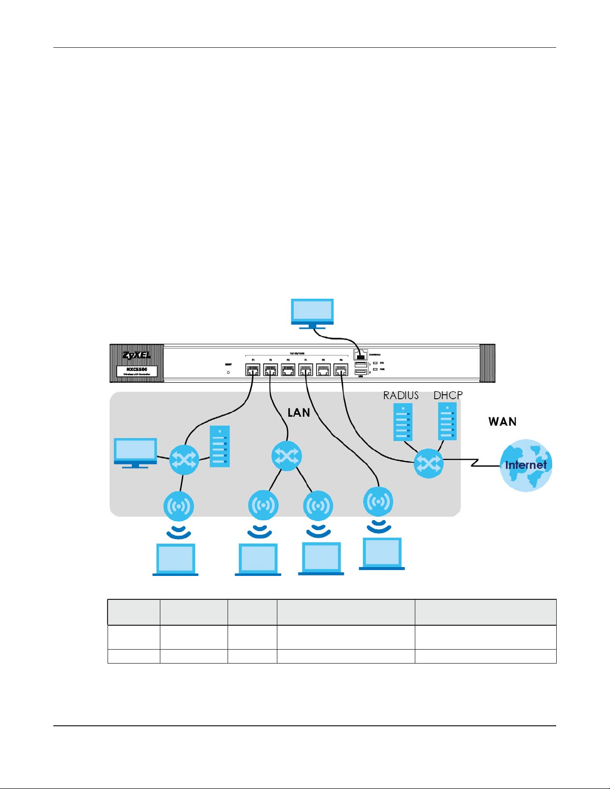
This section introduces the NXC’s default zone member physical interfaces and the default
configuration of those interfaces. This section uses the NXC5500 drawings as an example.
Figure 1 Default Network Topology
Table 3 Default Interfaces Configuration
PORT INTERFACE ZONE
P1~P6 ge1~ge6 LAN
(vlan0)
CONSOLE N/A None None Local management
• The LAN zone contains the ge1~ ge6 interfaces (physical ports P1~P6). By default, all LAN interfaces
are put in vlan0.
• The console port is not in a zone and can be directly accessed by a computer attached to it using a
special console-to-Ethernet adapter.
IP ADDRESS AND DHCP
SETTINGS
192.168.1.1, DHCP server disabled Dedicated LAN connections
NXC Series User’s Guide
SUGGESTED USE WITH DEFAULT
SETTINGS
19
Page 20
1.3 Applications
These are some example applications for your NXC.
1.3.1 AP Management
Manage multiple separate Access Points (APs) from a single, persistent location. APs can also be
configured to monitor for rogue APs.
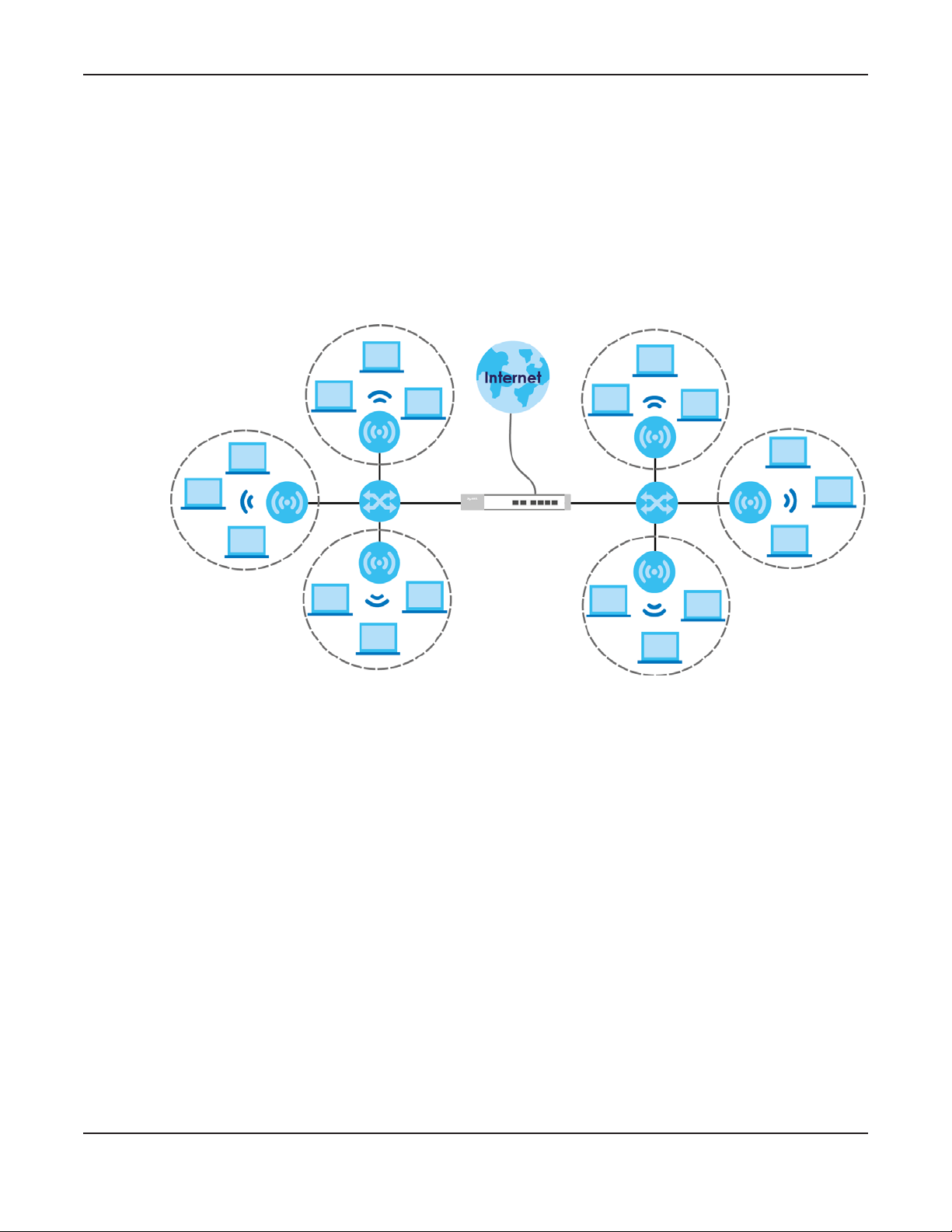
Figure 2 AP Management Example
Chapter 1 Introduction
Here, the NXC (A) connects to a number of Power over Ethernet (PoE) devices (B). They connect to the
managed Access Points (C), such as NWA5123-NI, which in turn provide access to the network for the
wireless clients (D) within their broadcast radius.
1.3.2 Wireless Security
Keep the connections between wireless clients and your APs secure with the NXC’s comprehensive
wireless security tools. APs can be configured to require WEP and WPA encryption from all wireless clients
attempting to associate with them. Furthermore, you can protect your network by monitoring for rogue
APs. Rogue APs are wireless access points operating in a network’s coverage area that are not under
the control of the network’s administrators, and can potentially open up critical holes in a network’s
security policy.
A
B
C
D
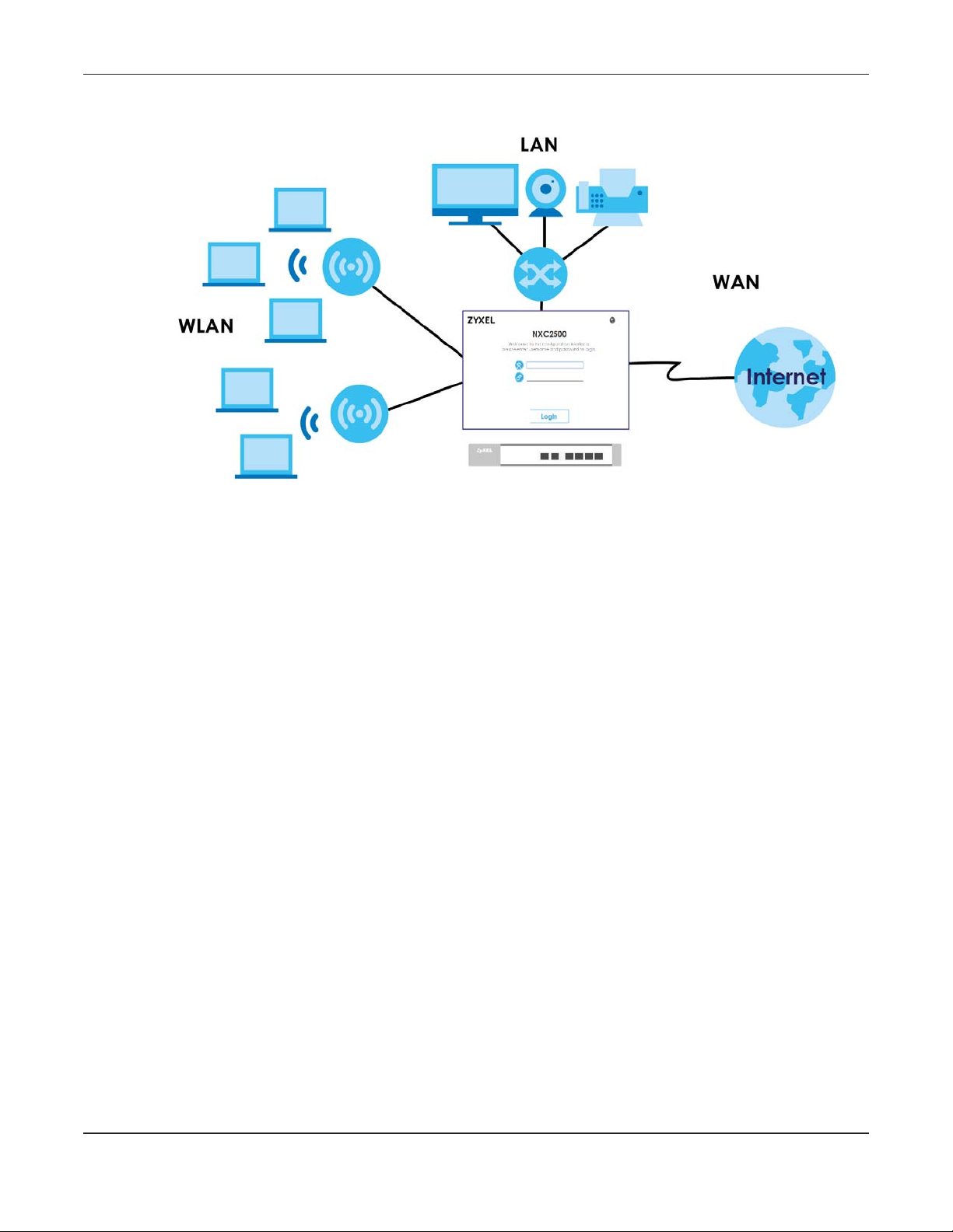
1.3.3 Captive Portal
The NXC can be configured with a captive portal, which intercepts all network traffic, regardless of
address or port, until a connecting user authenticates his or her session, through a designated login Web
page.
NXC Series User’s Guide
20
Page 21
Chapter 1 Introduction
Figure 3 Applications: Captive Portal
The captive portal page only appears once per authentication session. Unless a session times out or a
user closes the connection, he or she generally will not see it again during the same session.
1.3.4 Load Balancing
With load balancing you can easily distribute wireless traffic across multiple APs to relieve strain on your
network. When a station becomes overloaded, it can automatically delay a connection until the client
associates with another network, or it can alternatively disassociate idle clients or those clients with
weak connections from the network.
1.3.5 Dynamic Channel Selection
The NXC can automatically select the radio channel upon which its APs broadcast by scanning the
area around those APs and determining what channels are currently being used by other devices not
connected to the network.
1.3.6 User-Aware Access Control
Set up security policies that restrict access to sensitive information and shared resources based on the
user who is trying to access it.
NXC Series User’s Guide
21
Page 22

Chapter 1 Introduction
1.4 Management Overview
You can use the following ways to manage the NXC.
Web Configurator
The Web Configurator allows easy NXC setup and management using an Internet browser. This User’s
Guide provides information about the Web Configurator.
Command-Line Interface (CLI)
The CLI allows you to use text-based commands to configure the NXC. You can access it using remote
management (for example, SSH or Telnet) or via the physical or Web Configurator console port. See the
Command Reference Guide for CLI details. The default settings for the console port are as follows:
Table 4 Console Port Default Settings
SETTING VALUE
Speed 115200 bps
Data Bits 8
Parity None
Stop Bit 1
Flow Control Off
1.5 Object-based Configuration
The NXC stores information or settings as objects. You use these objects to configure many of the NXC’s
features and settings. Once you configure an object, you can reuse it in configuring other features.
When you change an object’s settings, the NXC automatically updates all the settings or rules that use
the object.
You can create address objects based on an interface’s IP address, subnet, or gateway. The NXC
automatically updates every rule or setting that uses these objects whenever the interface’s IP address
settings change. For example, if you change an Ethernet interface’s IP address, the NXC automatically
updates the rules or settings that use the interface-based, LAN subnet address object.
You can use the Configuration > Object screens to create objects before you configure features that
use them. If you are in a screen that uses objects, you can also usually select Create new Object to be
able to configure a new object.
Use the Object Reference screen to see what objects are configured and which configuration settings
reference specific objects.
NXC Series User’s Guide
22
Page 23

Chapter 1 Introduction
1.6 Starting and Stopping the NXC
Here are some of the ways to start and stop the NXC.
Always use Maintenance > Shutdown or the shutdown command
before you turn off the NXC or remove the power. Not doing so can
cause the firmware to become corrupt.
Table 5 Starting and Stopping the NXC
METHOD DESCRIPTION
Turning on the power A cold start occurs when you turn on the power to the NXC. The NXC powers up, checks
the hardware, and starts the system processes.
Rebooting the NXC A warm start (without powering down and powering up again) occurs when you use the
Reboot button in the Reboot screen or when you use the reboot command. The NXC
writes all cached data to the local storage, stops the system processes, and then does a
warm start.
Using the RESET button If you press the RESET button, the NXC sets the configuration to its default values and then
reboots.
Clicking Maintenance
> Shutdown >
Shutdown or using the
shutdown command
Disconnecting the
power
Clicking Maintenance > Shutdown > Shutdown or using the shutdown command writes all
cached data to the local storage and stops the system processes. Wait for the device to
shut down and then manually turn off or remove the power. It does not turn off the power.
Power off occurs when you turn off the power to the NXC. The NXC simply turns off. It does
not stop the system processes or write cached data to local storage.
The NXC does not stop or start the system processes when you apply configuration files or run shell scripts
although you may temporarily lose access to network resources.
NXC Series User’s Guide
23
Page 24
Hardware Installation and
2.1 Rack-mounted Installation
Note: Zyxel provides a sliding rail accessory for your use with your device. Please contact your
local vendor for details.
The NXC can be mounted on an EIA standard size, 19-inch rack or in a wiring closet with other
equipment. Follow the steps below to mount your NXC on a standard EIA rack using a rack-mounting kit.
Make sure the rack will safely support the combined weight of all the equipment it contains and that the
position of the NXC does not make the rack unstable or top-heavy. Take all necessary precautions to
anchor the rack securely before installing the unit.
CHAPTER 2
Connection
Note: Leave 10 cm of clearance at the sides and 20 cm in the rear.
Use a #2 Phillips screwdriver to install the screws.
Note: Failure to use the proper screws may damage the unit.
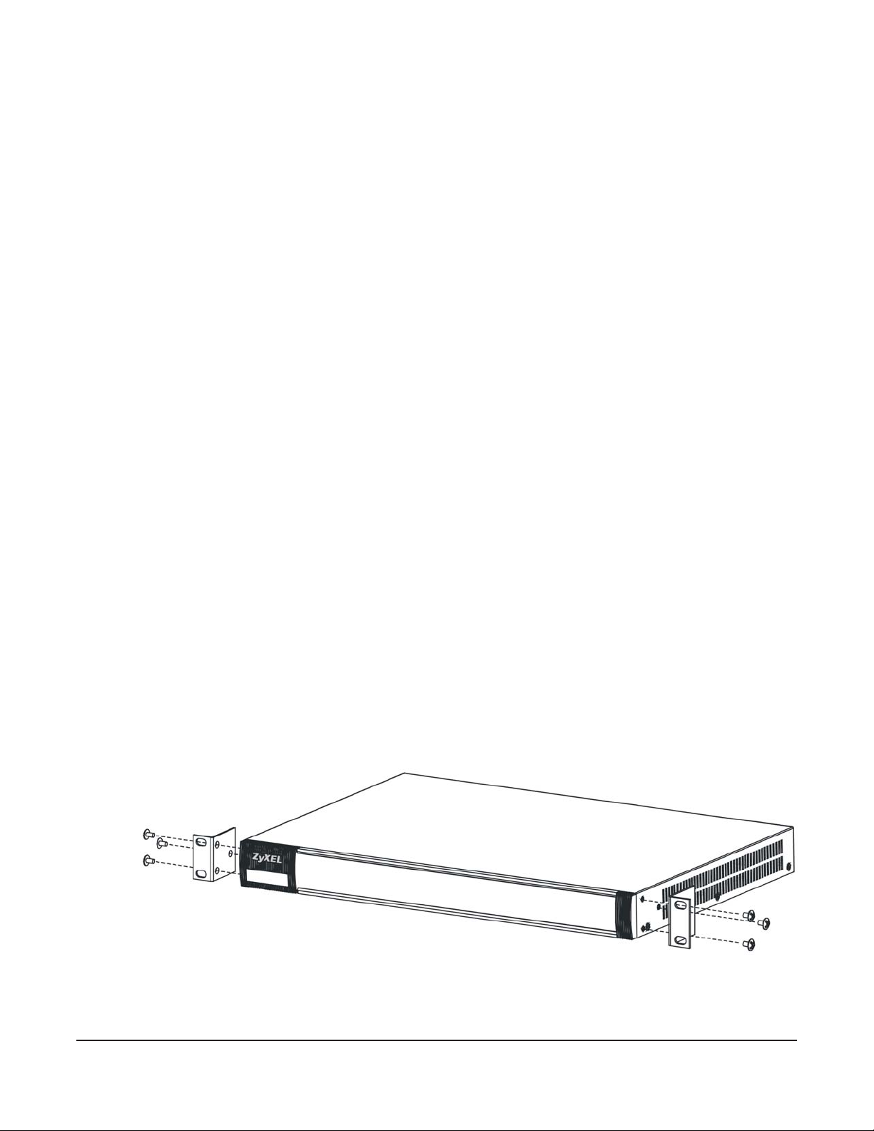
2.1.1 Rack-Mounted Installation Procedure
This section uses the NXC5500 drawings as an example.
1 Align one bracket with the holes on one side of the NXC and secure it with the included bracket screws
(smaller than the rack-mounting screws).
2 Attach the other bracket in a similar fashion.
NXC Series User’s Guide
24
Page 25
Chapter 2 Hardware Installation and Connection
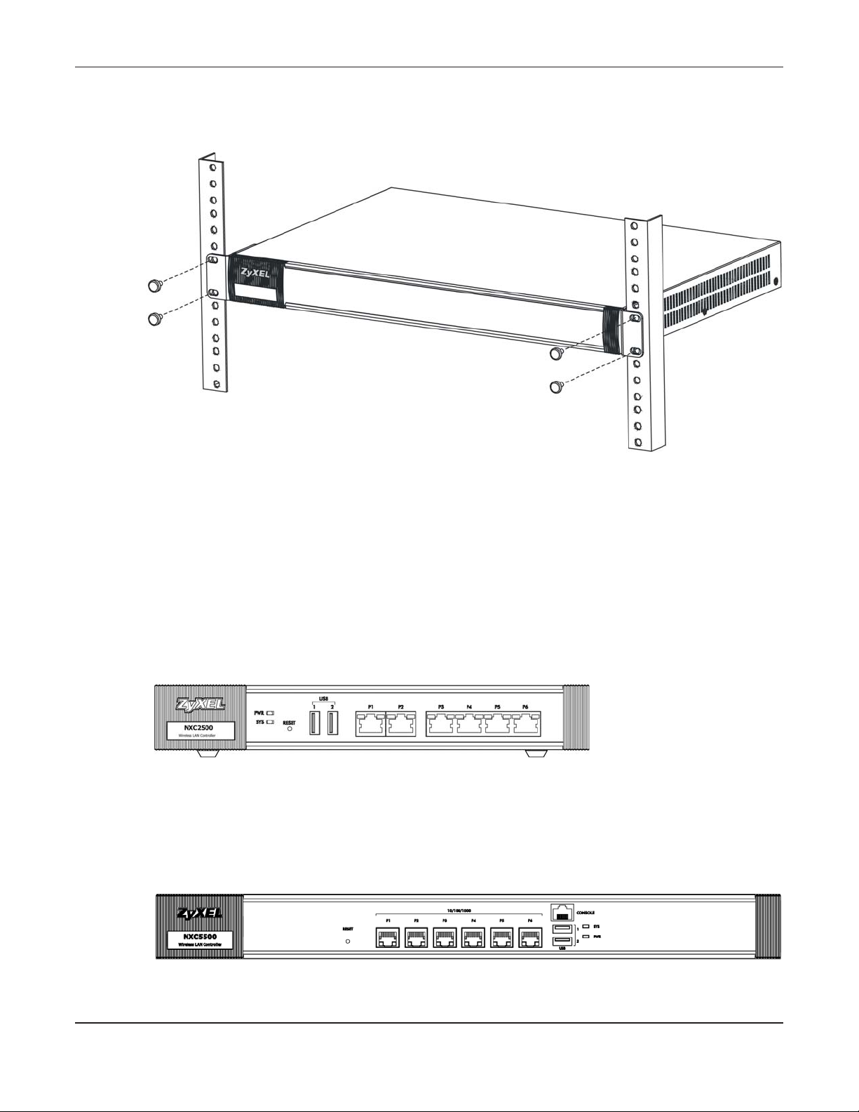
3 After attaching both mounting brackets, position the NXC in the rack by lining up the holes in the
brackets with the appropriate holes on the rack. Secure the NXC to the rack with the rack-mounting
screws.
2.2 Front Panel
This section gives you an overview of the front panel.
2.2.1 NXC2500
There are LEDs, one reset button, two USB ports and six Ethernet ports on the NXC2500 front panel.
Figure 4 Front Panel: NXC2500
2.2.2 NXC5500
There are one reset button, six Ethernet ports, one console port, two USB ports and LEDs on the NXC5500
front panel.
Figure 5 Front Panel: NXC5500
NXC Series User’s Guide
25
Page 26
Chapter 2 Hardware Installation and Connection
Ethernet Ports
The auto-negotiating, auto-crossover Ethernet ports support 10/100/1000 Mbps Gigabit Ethernet so the
speed can be 10 Mbps, 100 Mbps or 1000 Mbps. The duplex mode can be both half or full duplex at 10/
100 Mbps and full duplex only at 1000 Mbps. An auto-negotiating port can detect and adjust to the
optimum Ethernet speed and duplex mode of the connected device.
An auto-crossover (auto-MDI/MDI-X) port automatically works with a straight-through or crossover
Ethernet cable.
Default Ethernet Settings
The factory default negotiation settings for the Ethernet ports on the NXC are:
• Speed: Auto
• Duplex: Auto
• Flow control: On (you cannot configure the flow control setting, but the NXC can negotiate with the
peer and turn it off if needed)
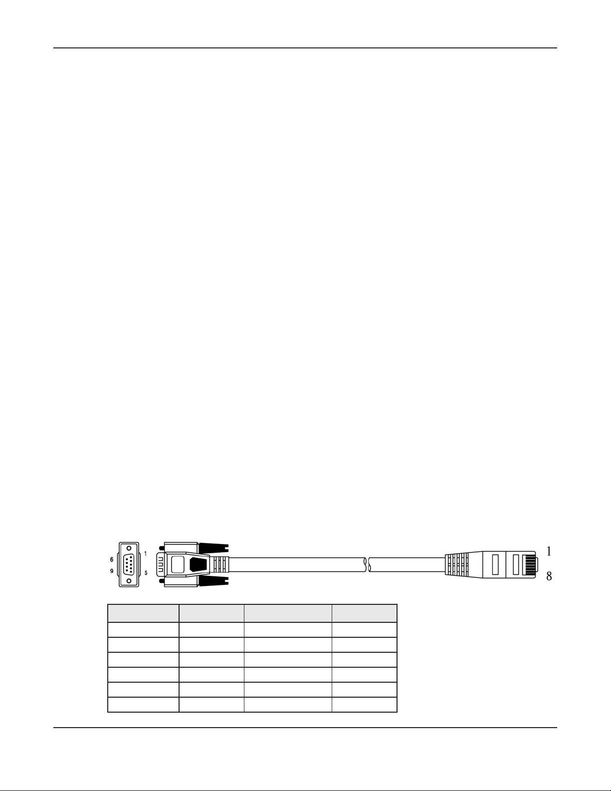
Console Port (NXC5500 Only)
Connect this port to your computer (using an RJ-45-to-DB-9 console cable) if you want to configure the
NXC using the command line interface (CLI) via the console port.
For local management, you can use a computer with terminal emulation software configured to the
following parameters:
• VT100 terminal emulation
• 115200 bps
• No parity, 8 data bits, 1 stop bit
• No flow control
Connect the RJ-45 connector of the console cable to the console port of the NXC. Connect the female
9-pin end of the console cable to a serial port (COM1, COM2 or other COM port) of your computer.
The following table shows you the wire color codes and pin assignment for the console cable.
Table 6 RJ-45-to-DB-9 Console Cable Color Codes
DB-9 SIGNAL DB-9 PIN# WIRE COLOR RJ45 PIN#
CTS 8 White/Orange 1
DSR/DCD 6+1 Orange 2
RD 2 White/Green 3
GND 5 Blue 4
GND 5 White/Blue 5
TD 3 Green 6
NXC Series User’s Guide
26
Page 27

Table 6 RJ-45-to-DB-9 Console Cable Color Codes
DB-9 SIGNAL DB-9 PIN# WIRE COLOR RJ45 PIN#
DTR 4 White/Brown 7
RTS 7 Brown 8
USB 2.0 Ports
Connect a USB storage device to a USB port on the NXC to archive the NXC system logs or save the NXC
operating system core dump to it.
2.2.3 Front Panel LEDs
This section describes the front panel LEDs.
2.2.3.1 NXC2500
The following table describes the LEDs.
Table 7 Front Panel LEDs: NXC2500
LED COLOR STATUS DESCRIPTION
PWR Off The NXC is turned off.
Green On The NXC is turned on.
SYS Green Off The NXC is not ready or has failed.
Red On There is a hardware component failure. Shut down the device, wait for a few
P1~P6 Green
(Traffic)
Orange
(Link)
Chapter 2 Hardware Installation and Connection
On The NXC is ready and running.
Blinking The NXC is booting.
minutes and then restart the device (see Section 1.6 on page 23). If the LED turns
red again, then please contact your vendor.
Blinking Firmware upgrade is in progress.
Blinking The NXC is sending or receiving packets to/from an Ethernet network on this
port.
Off The NXC is not sending or receiving packets on this port.
On This port has a successful link to an Ethernet network.
Off There is no connection on this port.
2.2.3.2 NXC5500
The following table describes the LEDs.
Table 8 Front Panel LEDs: NXC5500
LED COLOR STATUS DESCRIPTION
PWR Green Off The NXC is turned off.
On The NXC is turned on.
NXC Series User’s Guide
27
Page 28
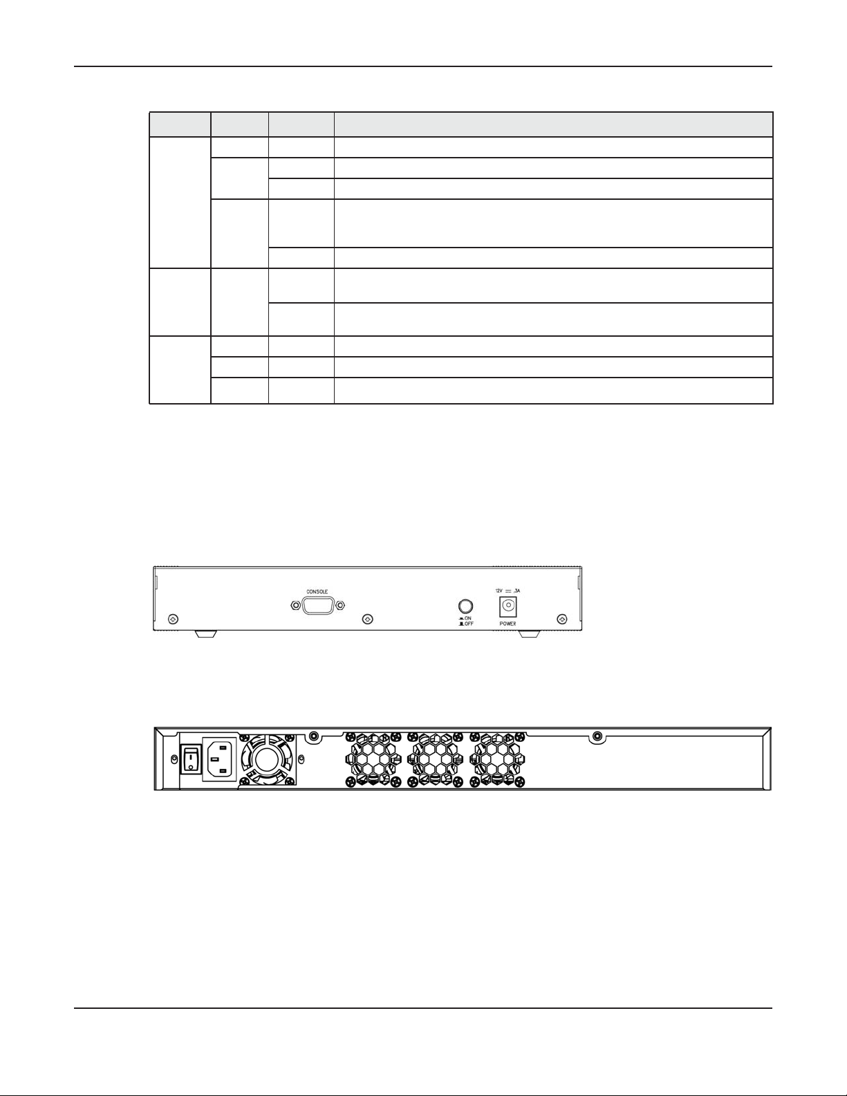
Chapter 2 Hardware Installation and Connection
Table 8 Front Panel LEDs: NXC5500 (continued)
LED COLOR STATUS DESCRIPTION
SYS Off The NXC is not ready or has failed.
Green On The NXC is ready and running.
Blinking The NXC is booting.
Red On There is a hardware component failure. Shut down the device, wait for a few
minutes and then restart the device (see Section 1.6 on page 23). If the LED turns
red again, then please contact your vendor.
Blinking Firmware upgrade is in progress.
P1~P6
Traffic
(Left)
P1~P6
Link
(Right)
Green Blinking The NXC is sending or receiving packets to/from an Ethernet network on this
port.
Off The NXC is not sending or receiving packets on this port.
Green On This Ethernet connection speed is 100 Mbps on this port.
Orange On This Ethernet connection speed is 1000 Mbps on this port.
Off There is no connection on this port.
2.3 Rear Panel
The NXC2500 rear panel contains a console port, a power switch and a connector for the power
receptacle.
Figure 6 Rear Panel: NXC2500
The NXC5500 rear panel contains a power switch, a connector for the power receptacle and a fan
module.
Figure 7 Rear Panel: NXC5500
Console Port (NXC2500 Only)
Connect this port to your computer (using an RS-232 cable) if you want to configure the NXC using the
command line interface (CLI) via the console port.
For local management, you can use a computer with terminal emulation software configured to the
following parameters:
• VT100 terminal emulation
• 115200 bps
NXC Series User’s Guide
28
Page 29

Chapter 2 Hardware Installation and Connection
• No parity, 8 data bits, 1 stop bit
• No flow control
Connect the male 9-pin end of the RS-232 console cable to the console port of the NXC. Connect the
female end to a serial port (COM1, COM2 or other COM port) of your computer.
NXC Series User’s Guide
29
Page 30
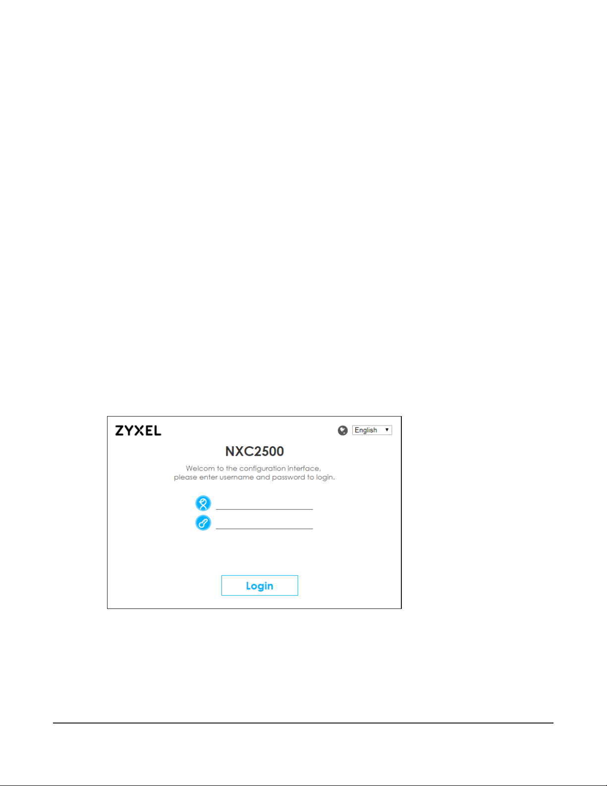
3.1 Overview
The NXC Web Configurator allows easy management using an Internet browser. Browsers supported
are:
• Firefox 36.0.1 or later
• Chrome 41.0 or later
• IE 10 or later
The recommended screen resolution is 1024 x 768 pixels and higher.
3.2 Access
CHAPTER 3
The Web Configurator
1 Make sure your NXC hardware is properly connected. See the Quick Start Guide.
2 Browse to https://192.168.1.1. The Login screen appears.
3 Enter the user name (default: “admin”) and password (default: “1234”). Select the language you prefer
for the Web Configurator.
4 Click Login. If you logged in using the default user name and password, the Update Admin Info screen
appears. Otherwise, the dashboard appears.
NXC Series User’s Guide
30
Page 31

Chapter 3 The Web Configurator
This screen appears every time you log in using the default user name and default password. If you
change the password for the default user account, this screen does not appear anymore.
3.3 The Main Screen
This guide uses the NXC2500 screens as an example. The screens may vary slightly for different models.
The Web Configurator’s main screen is divided into these parts:
NXC Series User’s Guide
31
Page 32

Chapter 3 The Web Configurator
Figure 8 The Web Configurator’s Main Screen
A
B
C
• A - Title Bar
• B - Navigation Panel
• C - Main Window
3.3.1 Title Bar
The title bar provides some useful links that always appear over the screens below, regardless of how
deep into the Web Configurator you navigate.
Figure 9 Title Bar
The icons provide the following functions.
Table 9 Title Bar: Web Configurator Icons
LABEL DESCRIPTION
Logout Click this to log out of the Web Configurator.
Wizard Click this to open screens where you can configure the NXC’s time zone, Internet access and
Help Click this to open the help page for the current screen.
About Click this to display basic information about the NXC.
Site Map Click this to see an overview of links to the Web Configurator screens.
wireless settings.
NXC Series User’s Guide
32
Page 33

Chapter 3 The Web Configurator
Table 9 Title Bar: Web Configurator Icons (continued)
LABEL DESCRIPTION
Object
Reference
CLI Message Click this to open a popup window that displays the CLI commands sent by the Web
Click this to open a screen where you can check which configuration items reference an
object.
Configurator.
About
Click About to display basic information about the NXC.
Figure 10 About
The following table describes labels that can appear in this screen.
Table 10 About
LABEL DESCRIPTION
Boot Module This shows the version number of the software that handles the booting process of the NXC.
Current Version This shows the firmware version of the NXC.
Released Date This shows the date (yyyy-mm-dd) and time (hh:mm:ss) when the firmware is released.
OK Click this to close the screen.
Site Map
Click Site MAP to see an overview of links to the Web Configurator screens. Click a screen’s link to go to
that screen.
NXC Series User’s Guide
33
Page 34

Figure 11 Site Map
Object Reference
Chapter 3 The Web Configurator
Click Object Reference to open the Object Reference screen. Select the type of object and the
individual object and click Refresh to show which configuration settings reference the object.
Figure 12 Object Reference
The fields vary with the type of object. The following table describes labels that can appear in this
screen.
Table 11 Object References
LABEL DESCRIPTION
Object Type Select the type of the object.
Object Name This identifies the object for which the configuration settings that use it are displayed. Select the
object’s name to display the object’s configuration screen in the main window.
# This field is a sequential value, and it is not associated with any entry.
Service This is the type of setting that references the selected object. Click a service’s name to display the
service’s configuration screen in the main window.
NXC Series User’s Guide
34
Page 35

Chapter 3 The Web Configurator
Table 11 Object References (continued)
LABEL DESCRIPTION
Priority If it is applicable, this field lists the referencing configuration item’s position in its list, otherwise N/A
displays.
Name This field identifies the configuration item that references the object.
Description If the referencing configuration item has a description configured, it displays here.
Refresh Click this to update the information in this screen.
Cancel Click Cancel to close the screen.
CLI Messages
Click CLI to look at the CLI commands sent by the Web Configurator. These commands appear in a
popup window, such as the following.
Figure 13 CLI Messages
Click Clear to remove the currently displayed information.
See the Command Reference Guide for information about the commands.
3.3.2 Navigation Panel
Use the menu items on the navigation panel to open screens to configure NXC features. Click the arrow
in the middle of the right edge of the navigation panel to hide the navigation panel menus or drag it to
resize them. The following sections introduce the NXC’s navigation panel menus and their screens.
NXC Series User’s Guide
35
Page 36

Figure 14 Navigation Panel
3.3.2.1 Dashboard
The dashboard menu screens display status information about the NXC.
Chapter 3 The Web Configurator
Table 12 Dashboard Menu Screens Summary
FOLDER OR LINK TAB FUNCTION
Dashboard Display general device information, system status, system resource
AP
Status Top N APs Display the number of wireless stations which are connected to the
Station
Traffic Top N Stations Display data usage of the top “N” wireless stations.
For details on the Dashboard’s features, see Chapter 5 on page 55.
3.3.2.2 Monitor Menu
The monitor menu screens display status and statistics information.
Table 13 Monitor Menu Screens Summary
FOLDER OR LINK TAB FUNCTION
System Status
Port Statistics Port Statistics Display packet statistics for each physical port.
Interface Status Interface
Traffic Statistics Traffic Statistics Collect and display traffic statistics.
Session Monitor Session Monitor Display the status of all current sessions.
usage, licensed service status, and interface status in widgets that you
can re-arrange to suit your needs.
top “N” managed APs and data usage.
Single AP Display the number of wireless stations which are connected to a
specific managed AP and data usage.
Single Station Display data usage of a specific wireless station.
Display general interface information and packet statistics.
Summary
NXC Series User’s Guide
36
Page 37

Chapter 3 The Web Configurator
Table 13 Monitor Menu Screens Summary (continued)
FOLDER OR LINK TAB FUNCTION
IP/MAC Binding IP/MAC Binding List the devices that have received an IP address from NXC interfaces
using IP/MAC binding.
Login Users Login Users List the users currently logged into the NXC.
Dynamic Guest List the dynamic guest accounts in the NXC’s local database.
Trusted MAC
Address List
USB Storage Storage
Information
Ethernet Neighbor Ethernet
Neighbor
Wireless
AP Information AP List Display information about the connected APs.
Radio List Display information about the radios of the connected APs.
ZyMesh ZyMesh Link Info Display statistics about the ZyMesh connections between the
SSID Info SSID Info Display information about the SSID’s wireless clients.
Station Info Station List Display information about the connected stations.
Detected Device Detected
Device
Log View Log List log entries for the NXC.
View AP Log Allow you to query connected APs and view log entries for them.
List the MAC addresses that are authenticated and allowed to access
the network.
Display details about a USB device connected to the NXC.
Display the NXC’s neighboring devices in one place.
managed APs.
Display information about suspected rogue APs.
3.3.2.3 Configuration Menu
Use the configuration menu screens to configure the NXC’s features.
Table 14 Configuration Menu Screens Summary
FOLDER OR LINK TAB FUNCTION
Licensing
Registration Registration Register the device.
Service View the licensed service status and upgrade licensed services.
Wireless
Controller Configuration Configure how the NXC handles APs that newly connect to the
AP
Management
Rogue AP Rogue/Friendly AP
Auto Healing Auto Healing Enable auto healing to extend the wireless service coverage area of
Network
Mgmt. AP List Edit wireless AP information, remove APs, and reboot them.
AP Policy Configure the AP controller’s IP address on the managed APs and
AP Group Configure AP groups, which define the radio, port, VLAN and load
Firmware Have the NXC check and download the latest AP firmware from the
List
network.
determine the action the managed APs take if the current AP
controller fails.
balancing settings and apply the settings to all APs in the group.
firmware server.
Configure how the NXC monitors for rogue APs.
the managed APs when one of the APs fails.
NXC Series User’s Guide
37
Page 38

Chapter 3 The Web Configurator
Table 14 Configuration Menu Screens Summary (continued)
FOLDER OR LINK TAB FUNCTION
Interface Ethernet Manage Ethernet interfaces and virtual Ethernet interfaces.
VLAN Create and manage VLAN interfaces and virtual VLAN interfaces.
LAG Combine multiple physical Ethernet interfaces into a single logical
interface.
Routing Policy Route Create and manage routing policies.
Static Route Create and manage IP static routing information.
Zone Zone Configure zones used to define various policies.
NAT NAT Set up and manage port forwarding rules.
ALG ALG Configure FTP pass-through settings.
IP/MAC Binding Summary Configure IP to MAC address bindings for devices connected to
each supported interface.
Exempt List Configure ranges of IP addresses to which the NXC does not apply IP/
MAC binding.
Captive Portal Captive Portal Enable captive portal and specify the captive portal page that
displays when a client makes an initial network connection.
Custom Captive
Portal
Redirect on
Controller
Redirect on AP Configure the authentication policy rules for the managed APs.
RTLS Real Time Location
System
Firewall Firewall Enable or disable the firewall and asymmetrical routes, and configure
Session Control Limit the number of concurrent NAT/firewall sessions a client can use.
Object
User/Group User Create and manage users.
Group Create and manage groups of users.
Setting Manage default settings for all users, general settings for user sessions,
MAC Address Map wireless client MAC addresses to MAC roles (MAC address user
AP Profile Radio Create and manage wireless radio settings files that can be
SSID Create and manage wireless SSID, security, MAC filtering and Layer-2
MON Profile MON Profile Create and manage rogue AP monitoring files that can be
ZyMesh Profile ZyMesh Profile Create and manage ZyMesh files that can be associated with
Address Address Create and manage host, range, and network (subnet) addresses.
Address Group Create and manage groups of addresses.
Service Service Create and manage TCP and UDP services.
Service Group Create and manage groups of services.
Schedule Schedule Create one-time and recurring schedules.
Create a customized login theme or upload one.
Allow clients to authenticate themselves to the NXC with a QR code,
and configure the authentication policy rules for the NXC.
Use the managed APs as part of an Ekahau RTLS to track the location
of Ekahau WiFi tags.
firewall rules.
and rules to force user authentication.
accounts).
associated with different APs.
isolation settings files that can be associated with different APs.
associated with different APs.
different APs.
NXC Series User’s Guide
38
Page 39

Chapter 3 The Web Configurator
Table 14 Configuration Menu Screens Summary (continued)
FOLDER OR LINK TAB FUNCTION
AAA Server Active Directory Configure the default Active Directory settings.
LDAP Configure the default LDAP settings.
RADIUS Configure the default RADIUS settings.
Auth. Method Authentication
Method
Certificate My Certificates Create and manage the NXC’s certificates.
Trusted Certificates Import and manage certificates from trusted sources.
DHCPv6 Request Configure DHCPv6 request type objects.
System
Host Name Host Name Configure the system and domain name for the NXC.
USB Storage USB Storage Configure the settings for the connected USB devices.
Date/Time Date/Time Configure the current date, time, and time zone in the NXC.
Console Speed Console Speed Set the console speed.
DNS DNS Configure the DNS server and address records for the NXC.
WWW Service Control Configure HTTP, HTTPS, and general authentication.
SSH SSH Configure SSH server and SSH service settings.
TELNET TELNET Configure telnet server settings for the NXC.
FTP FTP Configure FTP server settings.
SNMP SNMP Configure SNMP communities and services.
Auth. Server Auth. Server Configure the NXC to act as a RADIUS server.
Language Language Select the Web Configurator language.
IPv6 IPv6 Enables or disables IPv6 support on the NXC.
Log & Report
Email Daily
Report
Log Settings Log Settings Configure the system log, e-mail logs, and remote syslog servers.
Email Daily Report Configure where and how to send daily reports and what reports to
Create and manage ways of authenticating users.
send.
3.3.2.4 Maintenance Menu
Use the maintenance menu screens to manage configuration and firmware files, run diagnostics, and
reboot or shut down the NXC.
Table 15 Maintenance Menu Screens Summary
FOLDER OR LINK TAB FUNCTION
File Manager Configuration File Manage and upload configuration files for the NXC.
Firmware Package View the current firmware version and to upload firmware.
Shell Script Manage and run shell script files for the NXC.
NXC Series User’s Guide
39
Page 40

Table 15 Maintenance Menu Screens Summary (continued)
FOLDER OR LINK TAB FUNCTION
Diagnostics Diagnostics Collect diagnostic information.
Packet Capture Capture packets for analysis.
Core Dump Connect a USB device to the NXC and save the NXC operating
System Log Connect a USB device to the NXC and archive the NXC system logs
Wireless Frame
Capture
Packet Flow Explore Routing Status Check how the NXC determines where to route a packet.
SNAT Status View a clear picture on how the NXC converts a packet’s source IP
Reboot Reboot Restart the NXC.
Shutdown Shutdown Turn off the NXC.
3.3.3 Warning Messages
Warning messages, such as those resulting from misconfiguration, display in a popup window.
Chapter 3 The Web Configurator
system kernel to it here.
to it here.
Capture wireless frames from APs for analysis.
address and check the related settings.
Figure 15 Warning Message
3.3.4 Tables and Lists
The Web Configurator tables and lists are quite flexible and provide several options for how to display
their entries.
Manipulating Table Display
Here are some of the ways you can manipulate the Web Configurator tables.
1 Click a column heading to sort the table’s entries according to that column’s criteria.
NXC Series User’s Guide
40
Page 41

Chapter 3 The Web Configurator
2 Click the down arrow next to a column heading for more options about how to display the entries. The
options available vary depending on the type of fields in the column. Here are some examples of what
you can do:
• Sort in ascending alphabetical order
• Sort in descending (reverse) alphabetical order
• Select which columns to display
• Group entries by field
• Show entries in groups
• Filter by mathematical operators (<, >, or =) or searching for text.
3 Select a column heading cell’s right border and drag to re-size the column.
4 Select a column heading and drag and drop it to change the column order. A green check mark
displays next to the column’s title when you drag the column to a valid new location.
NXC Series User’s Guide
41
Page 42

Chapter 3 The Web Configurator
5 Use the icons and fields at the bottom of the table to navigate to different pages of entries and control
how many entries display at a time.
Working with Table Entries
The tables have icons for working with table entries. A sample is shown next. You can often use the [Shift]
or [Ctrl] key to select multiple entries to remove, activate, or deactivate.
Table 16 Common Table Icons
Here are descriptions for the most common table icons.
Table 17 Common Table Icons
LABEL DESCRIPTION
Add Click this to create a new entry. For features where the entry’s position in the numbered list is
Edit Double-click an entry or select it and click Edit to open a screen where you can modify the
Remove To remove an entry, select it and click Remove. The NXC confirms you want to remove it
important (features where the NXC applies the table’s entries in order), you can select an
entry and click Add to create a new entry after the selected entry.
entry’s settings. In some tables you can just click a table entry and edit it directly in the
table. For those types of tables small red triangles display for table entries with changes that
you have not yet applied.
before doing so.
NXC Series User’s Guide
42
Page 43

Chapter 3 The Web Configurator
Table 17 Common Table Icons (continued)
LABEL DESCRIPTION
Activate To turn on an entry, select it and click Activate.
Inactivate To turn off an entry, select it and click Inactivate.
Object References Select an entry and click Object References to open a screen that shows which settings use
the entry.
Move To change an entry’s position in a numbered list, select it and click Move to display a field to
type a number for where you want to put that entry and press [ENTER] to move the entry to
the number that you typed. For example, if you type 6, the entry you are moving becomes
number 6 and the previous entry 6 (if there is one) gets pushed up (or down) one.
Working with Lists
When a list of available entries displays next to a list of selected entries, you can often just double-click
an entry to move it from one list to the other. In some lists you can also use the [Shift] or [Ctrl] key to
select multiple entries, and then use the arrow button to move them to the other list.
Figure 16 Working with Lists
NXC Series User’s Guide
43
Page 44

4.1 Accessing the Wizard
Connect a router or switch with Internet access to port 1 (ge1), and your computer to ports 2-6 (ge 2-6)
of the NXC. When you log into the Web Configurator for the first time or when you reset the NXC to its
default configuration, the wizard screens display automatically. For subsequent logins, click the Wizard
icon at the top of any Web Configurator screen.
4.2 Using the Wizard
This wizard helps you configure the following settings:
1 For the NXC:
CHAPTER 4
Setup Wizard
• Country code
• Time zone
• Daylight saving
• IP address
• VLAN interfaces
2 For managed APs:
• Radio settings
• SSID profiles
4.2.1 Step 1 Password and Time Settings
Use this screen to configure the NXC’s system password, time zone and daylight savings time.
It’s important to have correct date and time values in the logs. If your NXC cannot get the correct date
and time, it may not be able to connect to a time server.
• New Password & Confirm Password: Enter a new password and retype it to confirm.
• Country: Select the country where the NXC is located.
• Time Zone: Select the time zone of your location. This will set the time difference between your time
zone and Greenwich Mean Time (GMT).
• Enable Daylight Savings: Select the option if you use Daylight Saving Time. Configure the day and
time when Daylight Saving Time starts and ends. The default daylight savings settings vary depending
on the time zone you selected.
• Offset allows you to specify how much the clock changes when daylight saving begins and ends.
Enter a number from 1 to 5.5 (by 0.5 increments).
NXC Series User’s Guide
44
Page 45

Chapter 4 Setup Wizard
Click Next to proceed. Click Cancel to close the wizard without saving.
Figure 17 Wizard: Step 1 Password and Time Settings
4.2.2 Step 2 Uplink Connection and Management VLAN
A Virtual Local Area Network (VLAN) allows you to group ports into multiple independent logical
networks.
Use this screen to configure the IP address of port 1 (ge1) for Internet access and configure vlan0, the
default management VLAN interface. The default members of vlan0 are ports 2-6 (ge2-6), and it uses
VLAN ID 1 by default. You can’t change the members in the Wizard.
• Uplink Connection: Select Auto (DHCP) if the NXC is connected to a router with the DHCP server
enabled. You then need to check the router for the IP address assigned to the NXC in order to access
the NXC’s web configurator again.
Otherwise, select Static IP when the NXC is NOT connected to a router or you want to assign it a fixed
IP address. You will need to manually enter:
• the NXC’s IP address and subnet mask.
• the IP address of the router that helps forward traffic.
• a DNS server's IP address. The Domain Name System (DNS) maps a domain name to an IP address
and vice versa.
• Untagged VLAN ID: This shows the ID number of the default management VLAN interface.
• IP Address & Subnet Mask: Configure the IP address, subnet mask, and gateway manually.
• DHCP: Select DHCP Server if you want the NXC to assign IP addresses to the connected devices.
Select DHCP Relay if you want a DHCP server to do so.
NXC Series User’s Guide
45
Page 46

Chapter 4 Setup Wizard
Figure 18 Wizard: Step 2 Uplink Connection and Management VLAN
4.2.3 Step 3 VLAN Settings
The NXC ports the managed APs are connected to must be in the same VLAN interface to
communicate with each other. Apart from this, you also need to connect your managed APs to the
correct ports according to the settings of the VLAN interface in order to communicate with the NXC.
Click the Add button to add a new VLAN interface, or select an entry and click the Edit button to
configure an existing VLAN interface.
• Name: This field displays the interface name of this VLAN.
• IP Address: This field displays the IP address of this VLAN.
• VID: This field displays the VLAN ID.
• Member: This field displays the ports that are members of this VLAN. You cannot configure members
for VLAN interfaces in the Wizard. The default members are ports 2-6 (ge2-6).
• Guest VLAN: This field displays whether this is a guest VLAN and whether the captive portal (web
authentication) feature is enabled.
NXC Series User’s Guide
46
Page 47

Chapter 4 Setup Wizard
Figure 19 Wizard: Step 3 VLAN Settings
4.2.3.1 Add/Edit VLAN Interfaces
Use this screen to add a new VLAN interface, or configure an existing VLAN interface.
• Interface Name: This field consists of the word vlan and the VLAN ID configured in the next field.
• Tagged VLAN ID: Configure your VLAN ID here. The allowed values are 2-4094. You cannot configure
duplicate VLANs.
• Guest VLAN: Select this option to have the VLAN act as a guest VLAN, on which you can enable a
captive portal.
• Restrict Internet Access: If you select Guest VLAN, you can define the local networks to which wireless
clients cannot have access. Therefore, clients associated with the managed APs connected to a port
in this guest VLAN are not allowed to access the specified networks.
• Captive Portal: If you select Guest VLAN, you can enable captive portal on the VLAN. You then select
to use either an internal captive web portal (built into the NXC) or external captive web portal (on an
external web server).
Click Edit Portal Theme to design customized portal pages.
• Walled Garden: If you select Guest VLAN, select this option and click Add or Remove to manage web
site addresses that all users can access without logging in. The web site link(s) displays in the user login
page.
• Create Dynamic Guest Manager: If you select Guest VLAN, select this option and enter a user name
and password to create a guest manager account. This user can log in via the web configurator login
screen and create dynamic guest accounts using the Guest Manager screen that pops up.
• IP Address & Subnet Mask: Configure the IP address, subnet mask, and gateway manually.
• DHCP: Select DHCP Server if you want the NXC to assign IP addresses to the connected devices.
Select DHCP Relay if you want a DHCP server to do so.
NXC Series User’s Guide
47
Page 48

Chapter 4 Setup Wizard
Figure 20 Wizard: Step 3 Add/Edit Interface
4.2.3.1.1 Add Customized Page
Use this screen to create a customized login theme.
• Picture Upload: Choose and upload a custom favorite icon or logo image for the customized login
page.
• Favorite Icon: The favorite icon is an image associated with the captive portal page. The icon
displays in the web browser's address bar and also next to the page’s title on the tab.
• Logo: The logo corresponds to the “Zyxel” logo image in the default page.
• Customized Login/Access/User-logout Page: Customize the other elements on the captive portal
login page, on the ‘access’ page that appears upon successful login or on the user logout page.
• Title: Enter 1-64 characters for the page title. Spaces are allowed.
• Title Color: Select a font color for the page title. You can use the color palette chooser, or enter a
color value of your own.
• Message Color: Specify the color of the screen’s text.
• Note Message: Enter a note to display below the title. Use up to 1024 printable ASCII characters.
Spaces are allowed.
• Background: Set how the window’s background looks.
To use a graphic, select Picture and upload a graphic. Specify the location and file name of the
graphic or click Browse to locate it. You can use the following image file formats: GIF, PNG, or JPG.
NXC Series User’s Guide
48
Page 49

Chapter 4 Setup Wizard
To use a color, select Color and specify the color.
Figure 21 Wizard: Step 3 Add/Edit Interface: Add Customized Page
4.2.4 Step 4 SSID
Use this screen to enable, disable or edit an SSID profile of a managed AP.
Select an SSID profile from the list, and click the On or Off icon to enable or disable the selected SSID
profiles of a managed AP by the NXC. To change an SSID profile’s settings, such as the SSID (WiFi
network name) and WiFi password, double-click the SSID profile from the list.
NXC Series User’s Guide
49
Page 50

Figure 22 Wizard: Step 4 SSID
Chapter 4 Setup Wizard
4.2.4.1 Edit SSID Profile
Use this screen to configure an SSID profile. The screen varies depending on the security mode you
select.
• Wireless Name (SSID) - Enter a descriptive name of up to 32 printable characters to identify the
wireless network on the manged AP.
• Status: Select Activate to enable the SSID profile. Otherwise, select Inactive to disable the profile.
• Guest VLAN: This field is available only when you create a guest VLAN interface in the previous
screen. Select this option to automatically add the guest VLAN tag to traffic from this SSID.
• Tagged VLAN ID: Select this option and Others, and then enter a VLAN ID for the managed AP to tag
traffic originating from this SSID. If you select Guest VLAN, this field is not configurable.
• Band Mode: Select the wireless band which this profile should use. 2.4 GHz is the frequency used by
IEEE 802.11b/g/n wireless clients. 5 GHz is the frequency used by IEEE 802.11ac/a/n wireless clients.
Not all managed APs support both 2.4 GHz and 5 GHz frequency bands.
• Security Mode: Select WPA2 to add security on this wireless network. Otherwise, select Open to allow
any wireless client to associate with this network without authentication.
• Pre-shared Key: If you set Security Mode to WPA2 and select Pre-Shared Key, enter a pre-shared key
of between 8 and 63 case-sensitive ASCII characters (including spaces and symbols) or 64
hexadecimal characters.
• 802.1x: Select 802.1x and the Primary / Secondary RADIUS Server Activate check box to have the
managed AP use the specified RADIUS server to authenticate their wireless clients. You have to enter
the IP address, port number and shared secret password of the RADIUS server to be used for
authentication. This option is not available if you select Guest VLAN.
Click OK to proceed. Click Cancel to close the screen without saving.
NXC Series User’s Guide
50
Page 51

Chapter 4 Setup Wizard
Figure 23 Wizard: SSID: Edit (802.1x)
Figure 24 Wizard: SSID: Edit (Pre-Shared Key)
4.2.5 Step 5 Radio
Use this screen to configure managed APs’ radio transmitter(s).
• Channel Selection: This shows Auto and the managed AP will automatically choose a radio channel
that has least interference.
NXC Series User’s Guide
51
Page 52

Chapter 4 Setup Wizard
• Channel Width: Select the wireless channel bandwidth you want the managed AP to use. Because
not all devices support 40 MHz and/or 80 MHz channels, select 20/40/80MHz to allow the AP to adjust
the channel bandwidth automatically.
• Maximum Output Power: Enter the maximum output power of the managed AP. If there is a high
density of APs in an area, decrease the output power of the managed AP to reduce interference
with other APs. The default output power settings vary depending on the time zone you selected.
Note: Reducing the output power also reduces the managed AP’s effective broadcast
radius.
Figure 25 Wizard: Step 5 Radio
4.2.6 Summary
Use this screen to check whether what you have configured is correct. Click Save to save your settings
and complete the wizard setup. Otherwise, click Prev to return to the previous screen or click Cancel to
close the wizard without saving.
To configure advanced settings on date/time, the uplink connection, a VLAN interface, and managed
APs, go to the configuration screens after you finish setting up the Wizard.
NXC Series User’s Guide
52
Page 53

Figure 26 Wizard: Summary
Chapter 4 Setup Wizard
NXC Series User’s Guide
53
Page 54

PART II
Technical Reference
54
Page 55

5.1 Overview
Use the Dashboard screens to check status information about the NXC.
5.1.1 What You Can Do in this Chapter
• The main Dashboard screen (Section 5.2 on page 56) displays the NXC’s general device information,
system status, system resource usage, licensed service status, and interface status. You can also
display other status screens for more information.
• The DHCP Table screen (Section 5.2.4 on page 61) displays the IP addresses currently assigned to
DHCP clients and the IP addresses reserved for specific MAC addresses.
• The Number of Login Users screen (Section 5.2.5 on page 62) displays the users currently logged into
the NXC.
• The AP > Status screen (Section 5.2.6 on page 63) displays how many wireless stations are connected
to the managed AP(s) and data usage.
• The Station > Traffic screen (Section 5.2.7 on page 65) displays data usage of the connected wireless
station(s).
CHAPTER 5
Dashboard
NXC Series User’s Guide
55
Page 56

5.2 Dashboard
This screen is the first thing you see when you log into the NXC. It also appears every time you click the
Dashboard icon in the navigation panel. The Dashboard displays general device information, system
status, system resource usage, licensed service status, and interface status in widgets that you can rearrange to suit your needs. You can also collapse, refresh, and close individual widgets.
Figure 27 Dashboard
Chapter 5 Dashboard
A
B
C
D
E
NXC Series User’s Guide
56
Page 57

Chapter 5 Dashboard
The following table describes the labels in this screen.
Table 18 Dashboard
LABEL DESCRIPTION
Widget Settings (A) Use this link to re-open closed widgets. Widgets that are already open appear grayed out.
Arrow (B) Click this to collapse or expand a widget.
Refresh Time Setting
(C)
Refresh Now (D) Click this to update the widget’s information immediately.
Close Widget (E) Click this to close the widget. Use Widget Settings to re-open it.
Virtual Device Hover your cursor over a LED or connected Ethernet port to view details about the status of
Name This field displays the name of the interface or slot.
Status This field displays the current status of each interface or device installed in a slot. The
Zone This field displays the zone to which the interface is currently assigned.
IP Address/Mask This field displays the current IP address and subnet mask assigned to the interface.
System Resources
CPU Usage This field displays what percentage of the NXC’s processing capability is currently being
Flash Usage This field displays what percentage of the NXC’s onboard flash memory is currently being
Memory Usage This field displays what percentage of the NXC’s RAM is currently being used. Click the
Session This field displays how many traffic sessions are currently open on the NXC. These are the
System Status
System Uptime This field displays how long the NXC has been running since it last restarted or was turned
Current Date/
Time
DHCP Table This field displays the number of IP addresses the NXC has assigned via DHCP. Click the link
Current Login
User
Number of Login
Users
Set the interval for refreshing the information displayed in the widget.
the NXC’s LEDs and connections. See Section 2.2.3 on page 27 for LED descriptions. An
unconnected interface appears grayed out.
The following labels display when you hover your cursor over a connected interface.
possible values depend on what type of interface it is.
Inactive - The Ethernet interface is disabled.
Down - The Ethernet interface is enabled but not connected.
Speed / Duplex - The Ethernet interface is enabled and connected. This field displays the
port speed and duplex setting (Full or Half).
used. Click the CPU Usage link to display a chart of the NXC’s recent CPU usage.
used.
Memory Usage link to display a chart of the NXC’s recent memory usage.
sessions that are traversing the NXC. Hover your cursor over this field to display icons. Click
the Session link to display a chart of NXC’s recent session usage.
on.
This field displays the current date and time in the NXC. The format is yyyy-mm-dd hh:mm:ss.
Click the link to open the screen where you can configure the NXC’s date and time.
to look at the IP addresses currently assigned to the NXC’s DHCP clients and the IP
addresses reserved for specific MAC addresses.
This field displays the user name used to log in to the current session, the amount of
reauthentication time remaining, and the amount of lease time remaining.
This field displays the number of users currently logged in to the NXC. Click the link to popopen a list of the users who are currently logged in to the NXC.
NXC Series User’s Guide
57
Page 58

Chapter 5 Dashboard
Table 18 Dashboard (continued)
LABEL DESCRIPTION
Boot Status This field displays details about the NXC’s startup state.
OK - The NXC started up successfully.
Firmware update OK - A firmware update was successful.
Problematic configuration after firmware update - The application of the configuration
failed after a firmware upgrade.
System default configuration - The NXC successfully applied the system default
configuration. This occurs when the NXC starts for the first time or you intentionally reset the
NXC to the system default settings.
Fallback to lastgood configuration - The NXC was unable to apply the startup-config.conf
configuration file and fell back to the lastgood.conf configuration file.
Fallback to system default configuration - The NXC was unable to apply the lastgood.conf
configuration file and fell back to the system default configuration file (systemdefault.conf).
Booting in progress - The NXC is still applying the system configuration.
Device Information
System Name This field displays the name used to identify the NXC on any network. Click the link to open
the screen where you can change it.
System Location This field displays the location of the NXC. Click the link to open the screen where you can
change it.
Model Name This field displays the model name of this NXC.
Serial Number This field displays the serial number of this NXC.
MAC Address
Range
Firmware Version This field displays the version number and date of the firmware the NXC is currently running.
Licensed Service Status
# This shows how many licensed services there are.
Status This is the current status of the license.
Name This identifies the licensed service.
Version This is the version number of the service.
Expiration If the service license is valid, this shows when it will expire. n/a displays if the service license
Extension Slot This section of the screen displays the status of the USB ports.
# This field displays how many USB ports there are.
Extension Slot This field displays the name of each extension slot.
Device This field displays the name of the device connected to the extension slot (or none if no
Status Ready - A USB storage device connected to the NXC is ready for the NXC to use.
AP Information This shows a summary of connected wireless Access Points (APs).
AP This displays the number of currently connected managed APs and the number of all
This field displays the MAC addresses used by the NXC. Each physical port has one MAC
address. The first MAC address is assigned to physical port 1, the second MAC address is
assigned to physical port 2, and so on.
Click the link to open the screen where you can upload firmware.
does not have a limited period of validity. 0 displays if the service is not licensed or has
expired.
device is detected).
none - The NXC is unable to mount a USB storage device connected to the NXC.
managed APs. Click the link to go to the Monitor > Wireless > AP information > AP List
screen.
NXC Series User’s Guide
58
Page 59

Chapter 5 Dashboard
Table 18 Dashboard (continued)
LABEL DESCRIPTION
Station This displays the number of stations currently connected to the network through managed
APs. Click the link to go to the Monitor > Wireless > Station Info > Station List screen.
ZyMesh A ZyMesh AP is a managed APs that act as a root AP or a repeater to form a ZyMesh. This
shows the number of currently connected ZyMesh APs and the number of all ZyMesh APs.
Click the link to go to the Monitor > Wireless > ZyMesh > ZyMesh Link Info screen.
2.4G / 5G Station This displays the number of stations connecting to the 2.4 GHz and 5 GHz networks
respectively.
Top 5 Station Displays the top 5 Access Points (APs) with the highest number of station (aka wireless client)
connections.
# This field displays the rank of the AP.
AP MAC This field displays the MAC address of the AP to which the station belongs.
Max. Station
Count
AP Description This field displays the AP’s description. The default description is “AP-” followed by the AP’s
Interface Status Summary
Name This field displays the name of each interface.
Status This field displays the current status of each interface. The possible values depend on what
Zone This field displays the zone to which the interface is currently assigned.
IP Addr/Netmask This field displays the current IP address and subnet mask assigned to the interface. If the IP
IP Assignment This field displays how the interface gets its IP address.
Action Use this field to get or to update the IP address for the interface.
The Latest Alert Logs This section of the screen displays recent logs generated by the NXC.
# This is the entry’s rank in the list of alert logs.
Time This field displays the date and time the log was created.
Priority This field displays the severity of the log.
Category This field displays the type of log generated.
Message This field displays the actual log message.
Source This field displays the source address (if any) in the packet that generated the log.
Destination This field displays the destination address (if any) in the packet that generated the log.
This field displays the maximum number of wireless clients that have connected to this AP.
MAC address.
type of interface it is.
Inactive - The Ethernet interface is disabled.
Down - The Ethernet interface is enabled but not connected.
Speed / Duplex - The Ethernet interface is enabled and connected. This field displays the
port speed and duplex setting (Full or Half).
address is 0.0.0.0, the interface is disabled or did not receive an IP address and subnet mask
via DHCP.
Static - This interface has a static IP address.
DHCP Client - This interface gets its IP address from a DHCP server.
Click Renew to send a new DHCP request to a DHCP server.
NXC Series User’s Guide
59
Page 60

5.2.1 CPU Usage
Use this screen to look at a chart of the NXC’s recent CPU usage. To access this screen, click Show CPU
Usage in the dashboard.
Figure 28 Dashboard > CPU Usage
Chapter 5 Dashboard
The following table describes the labels in this screen.
Table 19 Dashboard > CPU Usage
LABEL DESCRIPTION
Refresh Interval Enter how often you want this window to be automatically updated.
Refresh Now Click this to update the information in the window right away.
5.2.2 Memory Usage
Use this screen to look at a chart of the NXC’s recent memory (RAM) usage. To access this screen, click
Show Memory Usage in the dashboard.
Figure 29 Dashboard > Memory Usage
The y-axis represents the percentage of CPU usage.
The x-axis shows the time period over which the CPU usage occurred
NXC Series User’s Guide
60
Page 61

The following table describes the labels in this screen.
Table 20 Dashboard > Memory Usage
LABEL DESCRIPTION
Refresh Interval Enter how often you want this window to be automatically updated.
Refresh Now Click this to update the information in the window right away.
5.2.3 Session Usage
Use this screen to look at a chart of the NXC’s recent traffic session usage. To access this screen, click
Show Active Sessions in the dashboard.
Figure 30 Dashboard > Session Usage
Chapter 5 Dashboard
The y-axis represents the percentage of RAM usage.
The x-axis shows the time period over which the RAM usage occurred
The following table describes the labels in this screen.
Table 21 Dashboard > Session Usage
LABEL DESCRIPTION
Sessions The y-axis represents the number of session.
Refresh Interval Enter how often you want this window to be automatically updated.
Refresh Now Click this to update the information in the window right away.
5.2.4 DHCP Table
Use this screen to look at the IP addresses currently assigned to DHCP clients and the IP addresses
reserved for specific MAC addresses. To access this screen, click the link beside DHCP Table in the
dashboard.
The x-axis shows the time period over which the session usage occurred
NXC Series User’s Guide
61
Page 62

Chapter 5 Dashboard
Figure 31 Dashboard > DHCP Table
The following table describes the labels in this screen.
Table 22 Dashboard > DHCP Table
LABEL DESCRIPTION
# This field is a sequential value, and it is not associated with a specific entry.
Interface This field identifies the interface that assigned an IP address to a DHCP client.
IP Address This field displays the IP address currently assigned to a DHCP client or reserved for a specific
MAC address. Click the column’s heading cell to sort the table entries by IP address. Click the
heading cell again to reverse the sort order.
Host Name This field displays the name used to identify this device on the network (the computer name).
The NXC learns these from the DHCP client requests. “None” shows here for a static DHCP entry.
MAC Address This field displays the MAC address to which the IP address is currently assigned or for which the
IP address is reserved. Click the column’s heading cell to sort the table entries by MAC address.
Click the heading cell again to reverse the sort order.
Description For a static DHCP entry, the host name or the description you configured shows here. This field is
blank for dynamic DHCP entries.
Reserve If this field is selected, this entry is a static DHCP entry. The IP address is reserved for the MAC
address.
If this field is clear, this entry is a dynamic DHCP entry. The IP address is assigned to a DHCP
client.
To create a static DHCP entry using an existing dynamic DHCP entry, select this field.
To remove a static DHCP entry, clear this field.
5.2.5 Number of Login Users
Use this screen to look at a list of the users currently logged into the NXC. To access this screen, click the
dashboard’s Number of Login Users icon.
NXC Series User’s Guide
62
Page 63

Chapter 5 Dashboard
Figure 32 Dashboard > Number of Login Users
The following table describes the labels in this screen.
Table 23 Dashboard > Number of Login Users
LABEL DESCRIPTION
# This field is a sequential value and is not associated with any entry.
User ID This field displays the user name of each user who is currently logged in to the NXC.
Reauth/Lease
Time
Type This field displays the way the user logged in to the NXC.
IP address This field displays the IP address of the computer used to log in to the NXC.
User Info This field displays the types and user names of user accounts the NXC uses.
Force Logout Click this icon to end a user’s session.
This field displays the amount of reauthentication time remaining and the amount of lease time
remaining for each user.
If the user type is ext-user (external user), this field will show its external-group information when
you move your mouse over it. If the external user matches two external-group objects, both
external-group object names will be shown.
5.2.6 AP Status
Use this screen to view how many wireless stations are connected to the managed AP(s) and the data
usage. To access this screen, click Dashboard > AP > Status. Click the Single AP tab to view a specific
AP’s usage details, or click the Top N APs tab to view usage information for multiple APs at a time.
For the traffic usage bar chart, the y-axis shows the amount of data (in MB or GB) sent or received by the
stations connected to the selected AP(s). The x-axis shows the time period over which the traffic flow
occurred.
For the station count bar chart, the y-axis shows the number of the connected wireless stations. The xaxis shows the time period over which the number is recorded.
Move the cursor over a bar to see usage details over a specific time period. Click a bar to open the
Monitor > Wireless > Station Info > Station List screen and view information about the connected wireless
stations.
In the Top N APs screen, if you select Top 5 by Usage or Top 10 by Usage to show statistics for the top APs
which are ranked according to the AP’s data usage over the past 24 hours, the NXC also updates the
station count chart for these APs, and vice versa.
NXC Series User’s Guide
63
Page 64

Chapter 5 Dashboard
Figure 33 Dashboard > AP > Status: Top N APs
NXC Series User’s Guide
64
Page 65

Chapter 5 Dashboard
Figure 34 Dashboard > AP > Status: Single AP
5.2.7 Station Traffic
Use this screen to view data usage of the connected wireless station(s). To access this screen, click
Dashboard > Station > Traffic. Click the Single Station tab to view a specific wireless station’s usage
details, or click the Top N Stations tab to view usage information for multiple stations at a time.
The y-axis shows the amount of data (in MB or GB) consumed by the selected station(s). The x-axis shows
the time period over which the traffic flow occurred.
Move the cursor over a bar to see usage details over a specific time period.
NXC Series User’s Guide
65
Page 66

Chapter 5 Dashboard
Figure 35 Dashboard > Station > Traffic: Top N Stations
Figure 36 Dashboard > Station > Traffic: Single Station
NXC Series User’s Guide
66
Page 67

6.1 Overview
Use the Monitor screens to check status and statistics information.
6.1.1 What You Can Do in this Chapter
• The Port Statistics screen (Section 6.3 on page 69) displays packet statistics for each physical port.
• The Port Statistics Graph screen (Section 6.3.1 on page 70) displays a line graph of packet statistics for
each physical port.
• The Interface Status screen (Section 6.4 on page 71) displays all of the NXC’s interfaces and their
packet statistics.
• The Traffic Statistics screen (Section 6.5 on page 73) allows you to start or stop data collection and
view statistics.
• The Session Monitor screen (Section 6.6 on page 76) displays sessions by user or service.
• The IP/MAC Binding screen (Section 6.7 on page 78) displays lists of the devices that have received
an IP address from NXC interfaces with IP/MAC binding enabled.
• The Login Users screen (Section 6.8 on page 79) displays a list of the users currently logged into the
NXC.
• The Login Users > Dynamic Guest screen (Section 6.8.1 on page 80) displays a list of the guest user
accounts, which are created automatically and allowed to access the NXC’s services for a certain
period of time.
• The Login Users > Trusted MAC Address screen (Section 6.8.2 on page 81) displays a list of MAC
addresses, which are authenticated and allowed to access the network.
• The USB Storage screen (Section 6.9 on page 82) displays information about a connected USB storage
device.
• The Ethernet Neighbor screen (Section 6.10 on page 83) displays the NXC’s neighboring devices in
one place.
• The AP List screen (Section 6.11 on page 84) displays which APs are currently connected to the NXC.
• The Radio List screen (Section 6.12 on page 95) displays statistics about the wireless radio transmitters
in each of the APs connected to the NXC.
• The ZyMesh Link Info screen (Section 6.13 on page 98) displays statistics about the ZyMesh
connections between the managed APs.
• The SSID Info screen (Section 6.14 on page 99) displays the number of wireless clients that are
currently connected to an SSID and the SSID’s security mode.
• The Station List screen (Section 6.15 on page 100) displays statistics pertaining to the connected
stations (or “wireless clients”).
• The Detected Device screen (Section 6.16 on page 101) displays the wireless devices passively
detected by the NXC.
CHAPTER 6
Monitor
NXC Series User’s Guide
67
Page 68

Chapter 6 Monitor
• The View Log screen (Section 6.17 on page 103) displays the NXC’s current log messages. You can
change the way the log is displayed, you can e-mail the log, and you can also clear the log in this
screen.
• The View AP Log screen (Section 6.18 on page 105) displays the NXC’s current wireless AP log
messages.
6.2 What You Need to Know
The following terms and concepts may help as you read through the chapter.
Rogue AP
Rogue APs are wireless access points operating in a network’s coverage area that are not under the
control of the network’s administrators, and can open up holes in a network’s security. See Chapter 20
on page 266 for details.
Friendly AP
Friendly APs are other wireless access points that are detected in your network, as well as any others that
you know are not a threat (those from neighboring networks, for example). See Chapter 20 on page 266
for details.
Bluetooth Low Energy
Beacon is Apple’s communication protocol on top of Bluetooth Low Energy wireless technology.
Beacons (Bluetooth radio transmitters) or BLE enabled devices broadcast packets to every device
around it to announce their presence. Advertising packets contain their iBeacon ID which mainly
consists of the UUID, major number, minor number and TX (transmit) power. The ID is used to distinguish
beacons in your network.
The universally unique identifier (UUID) is a 128-bit (16-byte) number which can be used to identify a
service, a device, a manufacturer or an owner. The 2-byte major number is to identify and distinguish a
group, and the 2-byte minor number is to identify and distinguish an individual.
For example, you can set all the beacons in one network to share the same UUID, the beacons in a
particular room to use the same major number, and each beacon in the room can have its own minor
number.
NETWORK A
ROOM X ROOM Y
BEACON 1 BEACON 2 BEACON 3
UUID EBAECFAF-DFE0-4039-BE5A-F030EED4303C
Major 10 10 20
Minor 121
NXC Series User’s Guide
68
Page 69

6.3 Port Statistics
Use this screen to look at packet statistics for each Gigabit Ethernet port. To access this screen, click
Monitor > System Status > Port Statistics.
Figure 37 Monitor > System Status > Port Statistics
Chapter 6 Monitor
The following table describes the labels in this screen.
Table 24 Monitor > System Status > Port Statistics
LABEL DESCRIPTION
General Settings
Poll Interval Enter how often you want this window to be updated automatically, and click Set Interval.
Set Interval Click this to set the Poll Interval the screen uses.
Stop Click this to stop the window from updating automatically. You can start it again by setting the
Poll Interval and clicking Set Interval.
Statistics Table
Switch to Graphic
View
# This field displays the port’s number in the list.
Port This field displays the physical port number.
Status This field displays the current status of the physical port.
TxPkts This field displays the number of packets transmitted from the NXC on the physical port since it
RxPkts This field displays the number of packets received by the NXC on the physical port since it was
Collisions This field displays the number of collisions on the physical port since it was last connected.
Tx B/s This field displays the transmission speed, in bytes per second, on the physical port in the one-
Click this to display the port statistics as a line graph.
Down - The physical port is not connected.
Speed / Duplex - The physical port is connected. This field displays the port speed and duplex
setting (Full or Half).
was last connected.
last connected.
second interval before the screen updated.
NXC Series User’s Guide
69
Page 70

Table 24 Monitor > System Status > Port Statistics (continued)
LABEL DESCRIPTION
Rx B/s This field displays the reception speed, in bytes per second, on the physical port in the one-
second interval before the screen updated.
Up Time This field displays how long the physical port has been connected.
System Up Time This field displays how long the NXC has been running since it last restarted or was turned on.
6.3.1 Port Statistics Graph
Use the port statistics graph to look at a line graph of packet statistics for each physical port. To view,
click Monitor > System Status > Port Statistics and then the Switch to Graphic View button.
Figure 38 Monitor > System Status > Port Statistics > Switch to Graphic View
Chapter 6 Monitor
The following table describes the labels in this screen.
Table 25 Monitor > System Status > Port Statistics > Switch to Graphic View
LABEL DESCRIPTION
General Settings
Refresh Interval Enter how often you want this window to be automatically updated.
Refresh Now Click this to update the information in the window right away.
Port Usage
Port Selection Select the number of the physical port for which you want to display graphics.
Switch to Grid
View
Mbps/Kbps The y-axis represents the speed of transmission or reception.
time The x-axis shows the time period over which the transmission or reception occurred
Click this to display the port statistics as a table.
NXC Series User’s Guide
70
Page 71

Table 25 Monitor > System Status > Port Statistics > Switch to Graphic View (continued)
LABEL DESCRIPTION
TX This line represents traffic transmitted from the NXC on the physical port since it was last
connected.
RX This line represents the traffic received by the NXC on the physical port since it was last
connected.
Last Update This field displays the date and time the information in the window was last updated.
6.4 Interface Status
This screen lists all of the NXC’s interfaces and gives packet statistics for them. If you enabled IPv6 in the
Configuration > System > IPv6 screen, you can also view your IPv6 interface status on this screen. Click
Monitor > System Status > Interface Status to access this screen.
Figure 39 Monitor > System Status > Interface Status
Chapter 6 Monitor
NXC Series User’s Guide
71
Page 72

Chapter 6 Monitor
Each field is described in the following table.
Table 26 Monitor > System Status > Interface Status
LABEL DESCRIPTION
Interface Status
IPv6 Interface
Status
Name This field displays the name of each interface.
Port This field displays the physical port number.
Status This field displays the current status of each interface. The possible values depend on what
Zone This field displays the zone to which the interface is assigned.
IP Addr/Netmask
IP Address
IP Assignment This field displays how the interface gets its IP address.
Services This field lists which services the interface provides to the network. Examples include DHCP relay
Action Use this field to get or to update the IP address for the interface. Click Renew to send a new
Interface
Statistics
Refresh Click this button to update the information in the screen.
Name This field displays the name of each interface.
Use the Interface Status section for IPv4 network settings. Use the IPv6 Interface Status section
for IPv6 network settings if you connect your NXC to an IPv6 network. Both sections have similar
fields as described below.
type of interface it is.
For Ethernet interfaces:
Inactive - The Ethernet interface is disabled.
Down - The Ethernet interface is enabled but not connected.
Speed / Duplex - The Ethernet interface is enabled and connected. This field displays the port
speed and duplex setting (Full or Half).
For VLAN interfaces:
Up - The VLAN interface is enabled and one of its member Ethernet interfaces is connected.
Down - The VLAN interface is enabled but none of its member Ethernet interfaces is connected.
Inactive - The VLAN interface is disabled.
This field displays the current IP address (and subnet mask) of the interface. If the IP address
and subnet mask are 0.0.0.0 (in the IPv4 network) or the IP address is :: (in the IPv6 network), the
interface is disabled or does not have an IP address yet.
In the IPv6 network, this screen also shows whether the IP address is a static IP address (STATIC),
link-local IP address (LINK LOCAL), dynamically assigned (DHCP), or an IPv6 StateLess Address
AutoConfiguration IP address (SLAAC). See Appendix E on page 474 for more information
about IPv6.
Static - This interface has a static IP address.
DHCP Client - This interface gets its IP address from a DHCP server.
and DHCP server. This field displays n/a if the interface does not provide any services to the
network.
DHCP request to a DHCP server. Click Connect to try to connect the interface. If the interface
cannot use one of these ways to get or to update its IP address, this field displays n/a.
This table provides packet statistics for each interface.
NXC Series User’s Guide
72
Page 73

Chapter 6 Monitor
Table 26 Monitor > System Status > Interface Status (continued)
LABEL DESCRIPTION
Status This field displays the current status of each interface. The possible values depend on what
type of interface it is.
For Ethernet interfaces:
Inactive - The Ethernet interface is disabled.
Down - The Ethernet interface is enabled but not connected.
Speed / Duplex - The Ethernet interface is enabled and connected. This field displays the port
speed and duplex setting (Full or Half).
For VLAN interfaces:
Up - The VLAN interface is enabled and one of its member Ethernet interfaces is connected.
Down - The VLAN interface is enabled but none of its member Ethernet interfaces is connected.
Inactive - The VLAN interface is disabled.
TxPkts This field displays the number of packets transmitted from the NXC on the interface since it was
last connected.
RxPkts This field displays the number of packets received by the NXC on the interface since it was last
connected.
Tx B/s This field displays the transmission speed, in bytes per second, on the interface in the one-
second interval before the screen updated.
Rx B/s This field displays the reception speed, in bytes per second, on the interface in the one-second
interval before the screen updated.
6.5 Traffic Statistics
Click Monitor > System Status > Traffic Statistics to display this screen. This screen provides basic
information about the different kinds of data traffic moving through the NXC. For example:
• Most-visited Web sites and the number of times each one was visited. This count may not be accurate
in some cases because the NXC counts HTTP GET packets.
• Most-used protocols or service ports and the amount of traffic on each one.
• LAN IP with heaviest traffic and how much traffic has been sent to and from each one.
You use the Traffic Statistics screen to tell the NXC when to start and when to stop collecting information
for these reports. You cannot schedule data collection; you have to start and stop it manually in the
Traffic Statistics screen.
NXC Series User’s Guide
73
Page 74

Chapter 6 Monitor
Figure 40 Monitor > System Status > Traffic Statistics
There is a limit on the number of records shown in the report. See Table 28 on page 76 for more
information. The following table describes the labels in this screen.
Table 27 Monitor > System Status > Traffic Statistics
LABEL DESCRIPTION
Data Collection
Collect Statistics Select this to have the NXC collect data for the report. If the NXC has already been collecting
data, the collection period displays to the right. The progress is not tracked here real-time, but
you can click the Refresh button to update it.
Apply Click Apply to save your changes back to the NXC.
Reset Click Reset to return the screen to its last-saved settings.
Statistics
Interface Select the interface from which to collect information. You can collect information from
Ethernet or VLAN interfaces.
NXC Series User’s Guide
74
Page 75

Chapter 6 Monitor
Table 27 Monitor > System Status > Traffic Statistics (continued)
LABEL DESCRIPTION
Sort By Select the type of report to display. Choices are:
Host IP Address/User - displays the IP addresses or users with the most traffic and how much
traffic has been sent to and from each one.
Service/Port - displays the most-used protocols or service ports and the amount of traffic for
each one.
Web Site Hits - displays the most-visited Web sites and how many times each one has been
visited.
Each type of report has different information in the report (below).
Refresh Click this button to update the report display.
Flush Data Click this button to discard all of the screen’s statistics and update the report display.
These fields are available when the report type is Host IP Address/User.
# This field is the rank of each record. The IP addresses and users are sorted by the amount of
traffic.
Interface This field displays the interface(s) from which the NXC collects information.
Direction This field indicates whether the IP address or user is sending or receiving traffic.
Rx From- traffic is coming from the IP address or user to the NXC.
Tx To - traffic is going from the NXC to the IP address or user.
IP Address/User This field displays the IP address or user in this record. The maximum number of IP addresses or
users in this report is indicated in Table 28 on page 76.
Amount This field displays how much traffic was sent or received from the indicated IP address or user. If
the Direction is Rx From, a red bar is displayed; if the Direction is Tx To, a blue bar is displayed.
The unit of measure is bytes, Kbytes, Mbytes or Gbytes, depending on the amount of traffic for
the particular IP address or user. The count starts over at zero if the number of bytes passes the
byte count limit. See Table 28 on page 76.
These fields are available when the report type is Service/Port.
# This field is the rank of each record. The protocols and service ports are sorted by the amount
of traffic.
Interface This field displays the interface(s) from which the NXC collects information.
Service Port This field displays the service and port in this record. The maximum number of services and
service ports in this report is indicated in Table 28 on page 76.
Protocol This field indicates what protocol the service was using.
Direction This field indicates whether the indicated protocol or service port is sending or receiving traffic.
Ingress - traffic is coming into the NXC through the interface.
Egress - traffic is going out from the NXC through the interface.
Amount This field displays how much traffic was sent or received from the indicated service / port. If the
Direction is Ingress, a red bar is displayed; if the Direction is Egress, a blue bar is displayed. The
unit of measure is bytes, Kbytes, Mbytes, Gbytes, or Tbytes, depending on the amount of traffic
for the particular protocol or service port. The count starts over at zero if the number of bytes
passes the byte count limit. See Table 28 on page 76.
These fields are available when the report type is Web Site Hits.
# This field is the rank of each record. The domain names are sorted by the number of hits.
Interface This field displays the interface(s) from which the NXC collects information.
NXC Series User’s Guide
75
Page 76

Chapter 6 Monitor
Table 27 Monitor > System Status > Traffic Statistics (continued)
LABEL DESCRIPTION
Web Site This field displays the domain names most often visited. The NXC counts each page viewed on
a Web site as another hit. The maximum number of domain names in this report is indicated in
Table 28 on page 76.
Hits This field displays how many hits the Web site received. The NXC counts hits by counting HTTP
GET packets. Many Web sites have HTTP GET references to other Web sites, and the NXC counts
these as hits too. The count starts over at zero if the number of hits passes the hit count limit. See
Table 28 on page 76.
The following table displays the maximum number of records shown in the report, the byte count limit,
and the hit count limit.
Table 28 Maximum Values for Reports
LABEL DESCRIPTION
Maximum Number of Records 20
Byte Count Limit 264 bytes; this is just less than 17 million terabytes.
Hit Count Limit 264 hits; this is over 1.8 x 10¹⁹ hits.
6.6 Session Monitor
This screen displays information about active sessions for debugging or statistical analysis. It is not
possible to manage sessions in this screen. The following information is displayed.
• User who started the session
• Protocol or service port used
• Source IP address
• Destination IP address
• Number of bytes received (so far)
• Number of bytes transmitted (so far)
• Duration (so far)
You can look at all the active sessions by user, service, source IP address, or destination IP address. You
can also filter the information by user, protocol / service or service group, source address, and/or
destination address and view it by user.
Click Monitor > System Status > Session Monitor to display the following screen.
NXC Series User’s Guide
76
Page 77

Chapter 6 Monitor
Figure 41 Monitor > System Status > Session Monitor
The following table describes the labels in this screen.
Table 29 Monitor > System Status > Session Monitor
LABEL DESCRIPTION
Session
View Select how you want the information to be displayed. Choices are:
sessions by users - display all active sessions grouped by user
sessions by services - display all active sessions grouped by service or protocol
sessions by source IP - display all active sessions grouped by source IP address
sessions by destination IP - display all active sessions grouped by destination IP address
all sessions - filter the active sessions by the User, Service, Source Address, and Destination
Address, and display each session individually (sorted by user).
Refresh Click this button to update the information on the screen. The screen also refreshes
automatically when you open and close the screen.
The User, Service, Source Address, and Destination Address fields display if you view all sessions.
Select your desired filter criteria and click the Search button to filter the list of sessions.
User This field displays when View is set to all sessions. Type the user whose sessions you want to view.
It is not possible to type part of the user name or use wildcards in this field; you must enter the
whole user name.
Service This field displays when View is set to all sessions. Select the service or service group whose
sessions you want to view. The NXC identifies the service by comparing the protocol and
destination port of each packet to the protocol and port of each services that is defined. (See
Chapter 23 on page 280 for more information about services.)
Source
Address
Destination
Address
Search This button displays when View is set to all sessions. Click this button to update the information
# This field displays the index number of each active session.
This field displays when View is set to all sessions. Type the source IP address whose sessions you
want to view. You cannot include the source port.
This field displays when View is set to all sessions. Type the destination IP address whose sessions
you want to view. You cannot include the destination port.
on the screen using the filter criteria in the User, Service, Source Address, and Destination
Address fields.
NXC Series User’s Guide
77
Page 78

Chapter 6 Monitor
Table 29 Monitor > System Status > Session Monitor (continued)
LABEL DESCRIPTION
User This field displays the user in each active session.
If you are looking at the sessions by users (or all sessions) report, click + or - to display or hide
details about a user’s sessions.
Service This field displays the protocol used in each active session.
If you are looking at the sessions by services report, click + or - to display or hide details about
a protocol’s sessions.
Source This field displays the source IP address and port in each active session.
If you are looking at the sessions by source IP report, click + or - to display or hide details about
a source IP address’s sessions.
Destination This field displays the destination IP address and port in each active session.
If you are looking at the sessions by destination IP report, click + or - to display or hide details
about a destination IP address’s sessions.
Rx This field displays the amount of information received by the source in the active session.
Tx This field displays the amount of information transmitted by the source in the active session.
Duration This field displays the length of the active session in seconds.
6.7 IP/MAC Binding Monitor
Click Monitor > System Status > IP/MAC Binding to display the following screen. This screen lists the
devices that have received an IP address from NXC interfaces with IP/MAC binding enabled and have
ever established a session with the NXC. Devices that have never established a session with the NXC do
not display in the list.
Figure 42 Monitor > System Status > IP/MAC Binding
The following table describes the labels in this screen.
Table 30 Monitor > System Status > IP/MAC Binding
LABEL DESCRIPTION
Monitor Table
Interface Select a NXC interface that has IP/MAC binding enabled to show to which devices it has
assigned an IP address.
NXC Series User’s Guide
78
Page 79

Table 30 Monitor > System Status > IP/MAC Binding (continued)
LABEL DESCRIPTION
# This is the index number of an IP/MAC binding entry.
IP Address This is the IP address that the NXC assigned to a device.
Host Name This field displays the name used to identify this device on the network (the computer name).
MAC Address This field displays the MAC address to which the IP address is currently assigned.
Last Access This is when the device last established a session with the NXC through this interface.
Description This field displays the descriptive name that helps identify the entry.
Refresh Click this button to update the information in the screen.
6.8 Login Users
Use this screen to look at a list of the users currently logged into the NXC. To access this screen, click
Monitor > System Status > Login Users.
Figure 43 Monitor > System Status > Login Users
Chapter 6 Monitor
The NXC learns these from the DHCP client requests.
The following table describes the labels in this screen.
Table 31 Monitor > System Status > Login Users
LABEL DESCRIPTION
Current User List
Force Logout Select a user ID and click this icon to end a user’s session.
# This field is a sequential value and is not associated with any entry.
User ID This field displays the user name of each user who is currently logged into the NXC.
For a MAC authentication login, this field displays the MAC address of the user’s computer.
Reauth/Lease
Time
Associated AP This field displays the description of the managed AP through which the user logs into the NXC.
Type This field displays the way the user logged in to the NXC.
This field displays the amount of reauthentication time remaining and the amount of lease time
remaining for each user. See Chapter 18 on page 227.
The default description is “AP-” followed by the AP’s MAC address. A “-” displays if the user is
not connecting to the NXC wirelessly.
NXC Series User’s Guide
79
Page 80

Chapter 6 Monitor
Table 31 Monitor > System Status > Login Users
LABEL DESCRIPTION
IP address This field displays the IP address of the computer used to log into the NXC.
MAC Address This field displays the MAC address of the user’s computer.
Authenticator This field displays the IP address of the authenticator that helps clients to log in with a QR code.
A “-” displays if the user logged in without an authenticator’s help.
User Info This field displays the types of user accounts the NXC uses.
If the user type is ext-user (external user), this field will show its external-group information when
you move your mouse over it. If the external user matches two external-group objects, both
external-group object names will be shown.
Acct. Status For a captive portal login, this field displays the accounting status of the account used to log
into the NXC.
Accounting-on means accounting is being performed for the user login.
Accounting-off means accounting has stopped for this user login.
A “-” displays if accounting is not enabled for this login.
AAA Profile
Name
Refresh Click this button to update the information in the screen.
This field displays the name of the RADIUS profile used to authenticate the login through the
captive portal. N/A displays for logins that do not use the captive portal and RADIUS server
authentication.
6.8.1 Dynamic Guest
A dynamic guest account has a dynamically-created user name and password that allows a guest user
to access the Internet or the NXC’s services in a specified period of time. Multiple dynamic guest
accounts can be automatically generated at one time for guest users by using the web configurator
and the guest-manager account. Guest users can log in with the dynamic accounts when connecting
to an SSID for a specified time unit. Use this screen to look at a list of dynamic guest user accounts on the
NXC’s local database. To access this screen, click Monitor > System Status > Login Users > Dynamic
Guest.
Figure 44 Monitor > System Status > Login Users > Dynamic Guest
NXC Series User’s Guide
80
Page 81

Chapter 6 Monitor
The following table describes the labels in this screen.
Table 32 Monitor > System Status > Login Users > Dynamic Guest
LABEL DESCRIPTION
Dynamic Guest List
Remove Select an entry and click this button to remove it from the list.
Note: If you delete a valid user account which is in use, the NXC ends the user
session.
# This field is a sequential value and is not associated with any entry.
Status This field displays whether an account expires or not.
User ID This field displays the user name of the user account.
Reauth/Lease
Time
Expiration Time This field displays the date and time the user account becomes invalid.
IP Address This field displays the IP address of the computer used to log in to the NXC.
Group This field displays the name of the dynamic guest group to which the account belongs.
Guest Name This field displays the name of the person that uses the account.
Phone This field displays the telephone number for the user account.
Email This field displays the E-mail address for the user account.
Address This field displays the geographic address for the user account.
Company This field displays the company name for the user account.
Other This field displays the additional information for the user account.
Refresh Click this button to update the information in the screen.
This field displays the amount of reauthentication time remaining and the amount of lease time
remaining for each user. See Chapter 18 on page 227.
6.8.2 Trusted MAC Address List
This screen lists the wireless client which has been authenticated by MAC address and allowed to
access the network. To access this screen, click Monitor > System Status > Login Users > Trusted MAC
Address.
Figure 45 Monitor > System Status > Login Users > Trusted MAC Address List
NXC Series User’s Guide
81
Page 82

Chapter 6 Monitor
The following table describes the labels in this screen.
Table 33 Monitor > System Status > Login Users > Trusted MAC Address List
LABEL DESCRIPTION
Trusted MAC Address List
Remove Select an entry and click this button to remove it from the list.
Note: If you delete a MAC address, the client device of the MAC address needs to
log in via the captive portal page next time he/she wants to connect to the
same SSID.
# This field is a sequential value and is not associated with any entry.
User ID This field displays the user name of the client.
SSID Profile Name This field displays the name of the SSID profile in which the associated SSID is defined,
SSID This field displays the SSID to which the wireless client is currently connecting.
MAC Address This field displays the MAC address of the client device.
First Login Time This field displays the time the client first logged in to the NXC.
Validate Time This field displays the date and time the client becomes invalid and needs to re-authenticate
the connection.
6.9 USB Storage
This screen displays information about a connected USB storage device. Click Monitor > System Status >
USB Storage to display this screen.
Figure 46 Monitor > System Status > USB Storage
The following table describes the labels in this screen.
Table 34 Monitor > System Status > USB Storage
LABEL DESCRIPTION
Information
Device Description This is a basic description of the type of USB device.
Usage This field displays how much of the USB storage device’s capacity is currently being used
File System This field displays what file system the USB storage device is formatted with. This field displays
out of its total capacity and what percentage that makes.
Unknown if the file system of the USB storage device is not supported by the NXC, such as
NTFS.
NXC Series User’s Guide
82
Page 83

Chapter 6 Monitor
Table 34 Monitor > System Status > USB Storage (continued)
LABEL DESCRIPTION
Speed This field displays the connection speed the USB storage device supports.
Status Ready - you can have the NXC use the USB storage device.
Click Remove Now to stop the NXC from using the USB storage device so you can remove it.
Unused - the connected USB storage device was manually unmounted by using the
Remove Now button or for some reason the NXC cannot mount it.
Click Use It to have the NXC mount a connected USB storage device. This button is grayed
out if the file system is not supported (unknown) by the NXC.
none - no USB storage device is connected.
Detail This field displays any other information the NXC retrieves from the USB storage device.
Deactivated - the use of a USB storage device is disabled (turned off) on the NXC.
OutofSpace - the available disk space is less than the disk space full threshold (see Section
29.3 on page 321 for how to configure this threshold).
Mounting - the NXC is mounting the USB storage device.
Removing - the NXC is unmounting the USB storage device.
none - the USB device is operating normally or not connected.
6.10 Ethernet Neighbor
The NXC uses Smart Connect, that is Link Layer Discovery Protocol (LLDP) for discovering and configuring
LLDP-aware devices in the same broadcast domain as the NXC that you’re logged into using the web
configurator.
LLDP is a layer-2 protocol that allows a network device to advertise its identity and capabilities on the
local network. It also allows the device to maintain and store information from adjacent devices which
are directly connected to the network device. This helps you discover network changes and perform
necessary network reconfiguration and management.
Note: Smart Connect is enabled by default in the NXC.
Use this screen to view the NXC’s neighboring devices in one place. To access this screen, click Monitor
> System Status > Ethernet Neighbor.
Figure 47 Monitor > System Status > Ethernet Neighbor
NXC Series User’s Guide
83
Page 84

The following table describes the labels in this screen.
Table 35 Monitor > System Status > Ethernet Neighbor
LABEL DESCRIPTION
Local
Port(Description)
Model Name This field displays the model name of the discovered device.
System Name This field displays the system name of the discovered device.
Firmware Version This field displays the firmware version of the discovered device.
Port(Description) This field displays the discovered device’s port which is connected to the NXC.
IP Address This field displays the IP address of the discovered device. Click the IP address to log into and
MAC Address This field displays the MAC address of the discovered device.
Reset Click this button to update the information in the screen.
6.11 AP List
Chapter 6 Monitor
This field displays the port of the NXC, on which the neighboring device is discovered.
manage the discovered device using its web configurator.
Use this screen to view which APs are currently connected to the NXC. To access this screen, click
Monitor > Wireless > AP Information > AP List.
Figure 48 Monitor > Wireless > AP Information > AP List
The following table describes the labels in this screen.
Table 36 Monitor > Wireless > AP Information > AP List
LABEL DESCRIPTION
Hide/Show
Advanced
Settings
AP List
Enable Column
Freeze
Config AP Select an AP and click this to change the selected AP’s group, radio, VLAN and port settings.
Add to Mgmt AP
List
Click this button to display a greater or lesser number of configuration fields.
Select the check box to freeze the first column (#) so it will be always visible when you scroll
through the list. Clear the check box to unfreeze the column.
Select an AP and click this to add the selected AP to the managed AP list.
NXC Series User’s Guide
84
Page 85

Chapter 6 Monitor
Table 36 Monitor > Wireless > AP Information > AP List (continued)
LABEL DESCRIPTION
More Information Select an AP and click this to view a daily station count about the selected AP. The count
records station activity on the AP over a consecutive 24 hour period.
Reboot Select one or multiple APs and click this button to force the AP(s) to restart.
DCS Now Select one or multiple APs and click this button to use DCS (Dynamic Channel Selection) to
allow the AP to automatically find a less-used channel in an environment where there are
many APs and there may be interference.
Note: You should have enabled DCS in the applied AP radio profile before the APs
can use DCS.
Note: DCS is not supported on the radio which is working in repeater AP mode.
Log Select an AP and click this button to go to the Monitor > Log > View AP Log screen to view the
selected AP’s current log messages.
Suppression On Select an AP and click this button to enable the AP’s LED suppression mode. All the LEDs of the
AP will turn off after the AP is ready. This button is not available if the selected AP doesn’t
support suppression mode.
Suppression Off Select an AP and click this button to disable the AP’s LED suppression mode. The AP LEDs stay lit
after the AP is ready. This button is not available if the selected AP doesn’t support suppression
mode.
Upgrade Now Select one or more APs and click this button to update the APs’ firmware version.
# This is the AP’s index number in this list.
Status This visually displays the AP’s connection status with icons. For details on the different Status
states, see the next table.
Registration This indicates whether the AP is on the managed AP list (Mgmt AP) or not (Un-Mgmt AP).
This displays Limited AP when the AP is configured by conflicted or unsupported setting(s).
Description This displays the AP’s associated description. The default description is “AP-” + the AP’s MAC
Address.
CPU Usage This displays what percentage of the AP’s processing capability is currently being used.
IP Address This displays the AP’s IP address.
Model This displays the AP’s model number.
This field displays n/a if the NXC cannot get model information from the AP.
Version This displays the AP’s current firmware version.
Group This displays the name of the AP group to which the AP belongs.
Station This displays the number of stations (aka wireless clients) associated with the AP.
Recent On-line
Time
MAC Address This displays the AP’s MAC address.
Mgmt. VLAN
ID(AC/AP)
Last Off-line Time This displays the most recent time the AP went off-line. N/A displays if the AP has either not
This displays the most recent time the AP came on-line. N/A displays if the AP has not come on-
line since the NXC last started up.
This displays the Access Controller (the NXC) management VLAN ID setting for the AP and the
runtime management VLAN ID setting on the AP.
VLAN Conflict displays if the AP’s management VLAN ID does not match the NXC’s
management VLAN ID setting for the AP. This field displays n/a if the NXC cannot get VLAN
information from the AP.
come on-line or gone off-line since the NXC last started up.
NXC Series User’s Guide
85
Page 86

Chapter 6 Monitor
Table 36 Monitor > Wireless > AP Information > AP List (continued)
LABEL DESCRIPTION
LED Status This displays the AP LED status.
N/A displays if the AP does not support LED suppression mode and/or have a locator LED to
show the actual location of the AP.
A gray LED icon signifies that the AP LED suppression mode is enabled. All the LEDs of the AP will
turn off after the AP is ready.
A green LED icon signifies that the AP LED suppression mode is disabled and the AP LEDs stay lit
after the AP is ready.
A sun icon signifies that the AP’s locator LED is blinking.
A circle signifies that the AP’s locator LED is extinguished.
Ethernet Uplink This field displays the AP’s uplink port speed and duplex mode (Full or Half).
Power Mode This displays the AP’s power status.
Full - the AP receives power using a power adapter and/or through a PoE switch/injector using
IEEE 802.3at PoE plus. The PoE device that supports IEEE 802.3at PoE Plus can supply power of up
to 30W per Ethernet port.
Limited - the AP receives power through a PoE switch/injector using IEEE 802.3af PoE even when
it is also connected to a power source using a power adapter. The PoE device that supports
IEEE 802.3af PoE can supply power of up to 15.4W per Ethernet port.
When the AP is in limited power mode, the AP throughput decreases and has just one
transmitting radio chain, except WAC5302D-S.
It always shows Full if the AP does not support power detection. At the time of writing, only the
WAC6500 & WAC6300 series, WAC5302D-S and NWA5123-AC-HD APs support the power
detection feature.
Bluetooth This field displays the AP’s Bluetooth Low Energy (BLE) capability. Bluetooth Low Energy, which is
also known as Bluetooth Smart, transmits less data over a shorter distance and consumes less
power than classic Bluetooth. APs communicate with other BLE enabled devices using
advertisements.
N/A displays if the AP does not support BLE.
Unavailable displays if the AP supports Bluetooth, but there is no BLE device connected to the
USB port of the AP.
Available displays if the AP supports Bluetooth, detects a BLE device and advertising is inactive.
Advertising displays if the AP supports Bluetooth, detects a BLE device and advertising is
activated, which means the BLE device can broadcasts packets to every device around it.
Location This field displays the AP’s location you configured.
Roaming Group This field displays the name of roaming group to which the AP belongs.
S/N This field displays the serial number of the AP.
Refresh Click this button to update the information in the screen.
The following table describes the icons in this screen.
Table 37 Monitor > Wireless > AP Information > AP List Icons
LABEL DESCRIPTION
This AP is not on the management list.
This AP is on the management list and online.
This AP is in the process of having its firmware updated.
NXC Series User’s Guide
86
Page 87

Table 37 Monitor > Wireless > AP Information > AP List Icons (continued)
LABEL DESCRIPTION
This AP is on the management list but offline.
This indicates one of the following cases:
• This AP has a runtime management VLAN ID setting that conflicts with the VLAN ID setting on the
Access Controller (the NXC).
• A setting the NXC assigns to this AP does not match the AP’s capability.
• Packets sent out on a LAN port of this AP loop back to the AP.
This AP is offline and in the process of having its firmware updated.
This AP has a configuration conflict.
This AP is not supported and cannot be managed by the NXC.
6.11.1 Station Count of AP
Use this screen to look at configuration information, port status and station statistics for the connected
AP. To access this screen, select an entry and click the More Information button in the AP List screen.
Chapter 6 Monitor
NXC Series User’s Guide
87
Page 88

Chapter 6 Monitor
Figure 49 Monitor > Wireless > AP Information > AP List > AP Information
The following table describes the labels in this screen.
Table 38 Monitor > Wireless > AP Information > AP List > AP Information
LABEL DESCRIPTION
AP Information
Configuration
Status
Conflict If any of the AP’s configuration conflicts with the NXC’s settings for the AP, this field displays
This displays whether or not any of the AP’s configuration is in conflict with the NXC’s settings
for the AP.
which configuration conflicts. It displays n/a if none of the AP’s configuration conflicts with
the NXC’s settings for the AP.
NXC Series User’s Guide
88
Page 89

Chapter 6 Monitor
Table 38 Monitor > Wireless > AP Information > AP List > AP Information (continued)
LABEL DESCRIPTION
Non Support If any of the NXC’s settings for the AP are not supported by the AP, this field displays which
settings are not supported. It displays n/a if all the settings are supported by the AP.
Port Status
Port This shows the name of the physical Ethernet port on the AP.
Status This field displays the current status of each physical port on the AP.
Down - The port is not connected.
Speed / Duplex - The port is connected. This field displays the port speed and duplex setting
(Full or Half).
PVID This shows the port’s PVID.
A PVID (Port VLAN ID) is a tag that adds to incoming untagged frames received on a port so
that the frames are forwarded to the VLAN group that the tag defines.
Up Time This field displays how long the physical port has been connected.
Tx Bcast This field displays the number of broadcast packets transmitted on the port.
Rx Bcast This field displays the number of broadcast packets received on the port.
VLAN Configuration
Name This shows the name of the VLAN.
Status This displays whether or not the VLAN is activated.
VID This shows the VLAN ID number.
Member This field displays the Ethernet port(s) that is a member of this VLAN.
Ethernet Neighbor
Local
Port(Description)
Model Name This field displays the model name of the discovered device.
System Name This field displays the system name of the discovered device.
Firmware Version This field displays the firmware version of the discovered device.
Port(Description) This field displays the discovered device’s port which is connected to the AP.
IP Address This field displays the IP address of the discovered device. Click the IP address to access and
MAC Address This field displays the MAC address of the discovered device.
Station Count The y-axis represents the number of connected stations.
Last Update This field displays the date and time the information in the window was last updated.
OK Click OK to save your changes back to the NXC.
Cancel Click Cancel to close the window with changes unsaved.
This field displays the port of the AP, on which the neighboring device is discovered.
manage the discovered device using the web configurator.
The x-axis shows the time over which a station was connected.
6.11.2 Config AP
Use this screen to change the group and radio, VLAN, and port settings of the connected AP. To access
this screen, select an entry and click the Config AP button in the AP List screen.
NXC Series User’s Guide
89
Page 90

Chapter 6 Monitor
Figure 50 Monitor > Wireless > AP Information > AP List > Config AP
NXC Series User’s Guide
90
Page 91

Chapter 6 Monitor
The following table describes the labels in this screen.
Table 39 Monitor > Wireless > AP Information > AP List > Config AP
LABEL DESCRIPTION
Create new Object Use this menu to create a new Radio Profile, MON Profile, SSID Profile or ZyMesh Profile object
to associate with this AP.
Configuration
MAC This displays the MAC address of the selected AP.
Model This field displays the AP’s hardware model information. It displays N/A (not applicable) only
when the AP disconnects from the NXC and the information is unavailable as a result.
S/N This displays the serial number of the selected AP.
Description Enter a description for this AP. You can use up to 31 characters, spaces and underscores
allowed.
The system automatically generates a default name in the format of AP-xxxxxxxxxxxx (where
xxxxxxxxxxxx is the AP’s MAC address).
Group Setting Select an AP group to which you want this AP to belong.
System Name Enter a name to identify the AP on a network. This is usually the AP’s fully qualified domain
name.
Location Specify the name of the place where the AP is located.
Roaming Group Specify the name of the roaming group to which the AP belongs. You can use up to 31
alphanumeric and @# characters. Dashes and underscores are also allowed. The name
should start with a letter or digit.
The 802.11k neighbor list a client requests from the AP is generated according to the roaming
group and RCPI (Received Channel Power Indicator) value of its neighbor APs.
When a client wants to roam from the current AP to another, other APs in the same roaming
group or not in a roaming group will be candidates for roaming. Neighbor APs in a different
roaming group will be excluded from the 802.11k neighbor lists even when the neighbor AP
has the best signal strength.
If the AP’s roaming group is not configured, any neighbor APs can be candidates for
roaming.
Radio 1/2 Setting
Override Group
Radio Setting
Select this option to overwrite the AP radio settings with the settings you configure here.
NXC Series User’s Guide
91
Page 92

Chapter 6 Monitor
Table 39 Monitor > Wireless > AP Information > AP List > Config AP (continued)
LABEL DESCRIPTION
OP Mode Select the operating mode for radio 1 or radio 2.
AP Mode means the AP can receive connections from wireless clients and pass their data
traffic through to the NXC to be managed (or subsequently passed on to an upstream
gateway for managing).
MON Mode means the AP monitors the broadcast area for other APs, then passes their
information on to the NXC where it can be determined if those APs are friendly or rogue. If an
AP is set to this mode it cannot receive connections from wireless clients.
Root AP means the radio acts as an AP and also supports the wireless connections with other
APs (in repeater mode) to form a ZyMesh to extend its wireless network.
Repeater AP means the radio can establish a wireless connection with other APs (in either
root AP or repeater mode).
Note: To prevent bridge loops, do NOT set both radios on a managed AP to
Repeater AP mode.
Note: The root AP and repeater AP(s) in a ZyMesh must use the same country code
and AP radio profile settings in order to communicate with each other.
Note: Ensure you restart the managed AP after you change its operating mode.
Radio 1/2 AP Profile Select an AP profile from the list. If no profile exists, you can create a new one through the
Create new Object menu.
Radio 1/2 Profile Select a monitor mode profile from the list. If no profile exists, you can create a new one
through the Create new Object menu.
Radio 1/2 ZyMesh
Profile
Enable Wireless
Bridging
Override Group
Output Power
Setting
Max Output Power Enter the maximum output power of the AP.
Override Group
SSID Setting
Edit Select an SSID and click this button to reassign it. The selected SSID becomes editable
# This is the index number of the SSID profile. You can associate up to eight SSID profiles with an
SSID Profile Indicates which SSID profile is associated with this radio profile.
Bluetooth Advertising Setting
Edit Click this to edit the selected entry.
Activate To turn on an entry, select it and click Activate.
Inactivate To turn off an entry, select it and click Inactivate.
This field is available only when the radio is in Root AP or Repeater AP mode.
Select the ZyMesh profile the radio uses to connect to a root AP or repeater.
This field is available only when the radio is in Repeater AP mode.
Select this option to enable wireless bridging on the radio.
The managed AP must support LAN provision and the radio should be in repeater mode.
VLAN and bridge interfaces are created automatically according to the LAN port’s VLAN
settings. When wireless bridging is enabled, the managed repeater AP can still transmit data
through its Ethernet port(s) after the ZyMesh link is up. Be careful to avoid bridge loops.
The managed APs in the same ZyMesh must use the same static VLAN ID.
Select this option to overwrite the AP output power setting with the setting you configure
here.
Select this option to overwrite the AP SSID profile setting with the setting you configure here.
This section allows you to associate an SSID profile with the radio.
immediately upon clicking.
AP radio.
NXC Series User’s Guide
92
Page 93

Chapter 6 Monitor
Table 39 Monitor > Wireless > AP Information > AP List > Config AP (continued)
LABEL DESCRIPTION
# This field is a sequential value, and it is not associated with a specific entry.
Status This field shows whether or not the entry is activated.
A yellow bulb signifies that this rule is active. A gray bulb signifies that this rule is not active.
UUID This field indicates the UUID to be included in the Bluetooth advertising packets.
Major This field indicates the major number to be included in the Bluetooth advertising packets.
Minor This field indicates the minor number to be included in the Bluetooth advertising packets.
VLAN Settings
Override Group
VLAN Setting
Force Overwrite
VLAN Config
Management
VLAN ID
As Native VLAN Select this option to treat this VLAN ID as a VLAN created on the NXC and not one assigned
Port Settings
Override Group
LAN Setting
Port Setting This section displays only when you select Override Group LAN Setting.
Edit Double-click an entry or select it and click Edit to open a screen where you can modify the
Activate/
Inactivate
# This is the port’s index number in this list.
Status This displays whether or not the port is activated.
Port This shows the name of the physical Ethernet port on the managed AP.
PVID This shows the port’s PVID.
VLAN
Configuration
Add Click this to create a new entry.
Edit Double-click an entry or select it and click Edit to open a screen where you can modify the
Remove To remove an entry, select it and click Remove. The NXC confirms you want to remove it
Activate/
Inactivate
# This is the VLAN’s index number in this list.
Status This displays whether or not the VLAN is activated.
Name This shows the name of the VLAN.
VID This shows the VLAN ID number.
Member This field displays the Ethernet port(s) that is a member of this VLAN.
Rogue AP Detection Setting
Select this option to overwrite the AP VLAN setting with the setting you configure here.
Select this to have the NXC change the AP’s management VLAN to match the configuration
in this screen.
Enter a VLAN ID for this AP.
to it from outside the network.
Select this option to overwrite the AP LAN port settings with the settings you configure here.
entry’s settings.
To turn on an entry, select it and click Activate. To turn off an entry, select it and click
Inactivate.
A PVID (Port VLAN ID) is a tag that adds to incoming untagged frames received on a port so
that the frames are forwarded to the VLAN group that the tag defines.
This section displays only when you select Override Group LAN Setting.
entry’s settings.
before doing so.
To turn on an entry, select it and click Activate. To turn off an entry, select it and click
Inactivate.
NXC Series User’s Guide
93
Page 94

Chapter 6 Monitor
Table 39 Monitor > Wireless > AP Information > AP List > Config AP (continued)
LABEL DESCRIPTION
Override Group
Rogue AP
Detection Setting
Enable Rogue AP
Detection
LED Suppression Mode Configuration
This section is available only when the AP supports LED suppression mode.
Suppression On Select this option to enable the AP’s LED suppression mode. All the LEDs of the AP will turn off
Locator LED Configuration
This section is available only when the AP has a locator LED.
Turn On/Turn Off When the locator LED is off, click the Turn On button to activate the locator function. It will
Automatically
Extinguish After
OK Click OK to save your changes back to the NXC.
Cancel Click Cancel to close the window with changes unsaved.
Select this option to overwrite the AP Rogue Detection Settings with the settings you
configure here.
Select this option to detect Rogue APs in the network.
after the AP is ready.
If the check box is unchecked, it means the LEDs will stay lit after the AP is ready.
show the actual location of the AP between several devices in the network.
If the locator LED is blinking, click the Turn Off button to stop the locator LED from blinking
immediately.
Enter a time interval between 1 and 60 minutes to stop the locator LED from blinking. The
locator LED will start to blink for the number of minutes set here.
If you make changes to the time default setting, it will be stored as the default when the AP
restarts.
6.11.2.1 Edit Bluetooth Advertising
Use this screen modify the AP’s Bluetooth advertising settings.
To access this screen, click the Edit button in the Monitor > Wireless > AP information > AP List > Config AP
> Bluetooth Settings screen.
Figure 51 Monitor > Wireless > AP Information > AP List > Config AP > Bluetooth Settings > Edit
NXC Series User’s Guide
94
Page 95

The following table describes the labels in this screen.
Table 40 Monitor > Wireless > AP Information > AP List > Config AP > Bluetooth Settings > Edit
LABEL DESCRIPTION
General Settings
Activate Select this option to enable the Bluetooth advertising settings.
UUID To specify a UUID of the AP’s beacon ID, enter 32 hexadecimal digits in the range of “A-
Generate new UUID Click this button to have the AP generate a UUID automatically.
Major Enter an integer from 0 to 65535 as the major value to identify the beacon.
Minor Enter an integer from 0 to 65535 as the minor value to identify the beacon.
OK Click OK to save your changes back to the AP.
Cancel Click Cancel to exit this screen without saving your changes.
6.12 Radio List
Chapter 6 Monitor
F”, “a-f” and “0-9”, split into five groups separated by hyphens (-). The UUID format is as
follows: xxxxxxxx-xxxx-xxxx-xxxx-xxxxxxxxxxxx (8-4-4-4-12).
Use this screen to view statistics about the wireless radio transmitters in each of the APs connected to the
NXC. To access this screen, click Monitor > Wireless > AP Information > Radio List.
Figure 52 Monitor > Wireless > AP Information > Radio List
The following table describes the labels in this screen.
Table 41 Monitor > Wireless > AP Information > Radio List
LABEL DESCRIPTION
Hide/Show
Advanced
Settings
Radio List
Enable Column
Freeze
More Information Click this to view additional information about the selected radio’s SSID(s), wireless traffic and
Click this button to display a greater or lesser number of configuration fields.
Select the check box to freeze the first column (#) so it will be always visible when you scroll
through the list. Clear the check box to unfreeze the column.
wireless clients. Information spans a 24 hour period.
NXC Series User’s Guide
95
Page 96

Chapter 6 Monitor
Table 41 Monitor > Wireless > AP Information > Radio List (continued)
LABEL DESCRIPTION
# This is the radio’s index number in this list.
Loading This indicates the AP’s load balance status (UnderLoad or OverLoad) when load balancing is
enabled on the AP. Otherwise, it shows - when load balancing is disabled or the radio is in
monitor mode.
AP Description This displays the description of the AP to which the radio belongs.
Frequency Band This indicates the wireless frequency currently being used by the radio.
This shows - when the radio is in monitor mode.
Channel ID This indicates the radio’s channel ID.
Tx Power This shows the radio’s output power (in dBm).
Station This displays the number of stations (aka wireless clients) associated with the radio.
Rx This displays the total number of bytes received by the radio.
Tx This displays the total number of bytes transmitted by the radio.
Model This displays the model of the AP to which the radio belongs.
MAC Address This displays the MAC address of the radio.
Radio This indicates the radio number on the AP to which it belongs.
OP Mode This indicates the radio’s operating mode. Operating modes are AP (access point), MON
(monitor), Root AP or Repeater.
AP / ZyMesh
Profile
Antenna This indicates the antenna orientation for the radio (Wall or Ceiling).
Refresh Click this button to update the information in the screen.
This indicates the AP radio and ZyMesh profile names to which the radio belongs.
This shows N/A if the AP does not allow you to adjust coverage depending on the orientation of
the antenna for each radio using the web configurator or a physical switch.
The following table describes the icons in this screen.
Table 42 Monitor > Wireless > AP Information > Radio List Icons
LABEL DESCRIPTION
When an AP is being load balanced, this icon means it is operating over the maximum
allocated bandwidth.
When an AP is being load balanced, this icon means it is operating under the maximum
allocated bandwidth.
6.12.1 AP Mode Radio Information
This screen allows you to view detailed information about a selected radio’s SSID(s), wireless traffic and
wireless clients for the preceding 24 hours. To access this window, select an entry and click the More
Information button in the Radio List screen.
NXC Series User’s Guide
96
Page 97

Chapter 6 Monitor
Figure 53 Monitor > Wireless > AP Information > Radio List > AP Mode Radio Information
NXC Series User’s Guide
97
Page 98

Chapter 6 Monitor
The following table describes the labels in this screen.
Table 43 Monitor > Wireless > AP Info > Radio List > AP Mode Radio Information
LABEL DESCRIPTION
MBSSID Detail This list shows information about the SSID(s) that is associated with the radio over the preceding
24 hours.
# This is the items sequential number in the list. It has no bearing on the actual data in this list.
SSID Name This displays an SSID associated with this radio. There can be up to eight maximum.
BSSID This displays the MAC address associated with the SSID.
Security
Mode
Forwarding
Mode
VLAN This displays the VLAN ID associated with the SSID.
Traffic Statistics This graph displays the overall traffic information about the radio over the preceding 24 hours.
y-axis This axis represents the amount of data moved across this radio in megabytes per second.
x-axis This axis represents the amount of time over which the data moved across this radio.
Station Count This graph displays information about all the wireless clients that have connected to the radio
y-axis The y-axis represents the number of connected wireless clients.
x-axis The x-axis shows the time over which a wireless client was connected.
Last Update This field displays the date and time the information in the window was last updated.
OK Click this to close this window.
Cancel Click this to close this window.
This displays the security mode in which the SSID is operating.
This field indicates the forwarding mode (Local Bridge or Tunnel) associated with the SSID
profile.
over the preceding 24 hours.
6.13 ZyMesh Link Info
Use this screen to view the ZyMesh traffic statistics between the managed APs. Click Monitor > Wireless >
ZyMesh > ZyMesh Link Info to access this screen.
Figure 54 Monitor > Wireless > ZyMesh > ZyMesh Link Info
NXC Series User’s Guide
98
Page 99

Chapter 6 Monitor
The following table describes the labels in this screen.
Table 44 Monitor > Wireless > ZyMesh > ZyMesh Link Info
LABEL DESCRIPTION
Hide/Show
Advanced
Settings
ZyMesh Link Info
Enable Column
Freeze
# This is the index number of the managed AP (in repeater mode) in this list.
Description This is the descriptive name of the managed AP (in repeater mode).
IP Address This is the IP address of the managed AP (in repeater mode).
Channel ID This is the number of the channel used by the managed AP (in repeater mode).
Hop This is the hop count of the managed AP. For example, “1” means the managed AP is
Uplink AP Info This shows the role and descriptive name of the managed AP to which this managed AP is
SSID Name This indicates the name of the wireless network (SSID) the managed AP uses to associated with
Signal Strength Before the slash, this shows the signal strength the uplink AP (a root AP or a repeater) receives
Link Up Time This displays the time the managed AP first associated with the root AP or repeater.
MAC Address This is the MAC address of the managed AP (in repeater mode).
Tx Power This is the output power of the managed AP (in repeater mode).
Root AP This is the descriptive name of the root AP to which the managed AP is connected wirelessly.
Tx Rate This is the maximum transmission rate of the root AP or repeater to which the managed AP is
Rx Rate This is the maximum reception rate of the root AP or repeater to which the managed AP is
Refresh Click this button to update the information in the screen.
Click this button to display a greater or lesser number of configuration fields.
Select the check box to freeze the first column (#) so it will be always visible when you scroll
through the list. Clear the check box to unfreeze the column.
connected to a root AP directly. “2” means there is another repeater AP between the
managed AP and the root AP.
connected wirelessly.
another managed AP.
from this managed AP (in repeater mode).
After the slash, this shows the signal strength this managed AP (in repeater mode) receives from
the uplink AP.
connected.
connected.
6.14 SSID Info
Use this screen to view the number of wireless clients currently connected to an SSID and the security
type used by the SSID. Click Monitor > Wireless > SSID Info to access this screen.
NXC Series User’s Guide
99
Page 100

Chapter 6 Monitor
Figure 55 Monitor > Wireless > SSID Info
The following table describes the labels in this screen.
Table 45 Monitor > Wireless > SSID Info
LABEL DESCRIPTION
# This is the SSID’s index number in this list.
SSID This indicates the name of the wireless network to which the client is connected. A single AP
can have multiple SSIDs or networks.
2.4GHz This shows the number of wireless clients which are currently connected to the SSID using the 2.4
GHz frequency band, Click the number to go to the Station Info > Station List screen. See
Section 6.15 on page 100.
5GHz This shows the number of wireless clients which are currently connected to the SSID using the 5
GHz frequency band, Click the number to go to the Station Info > Station List screen. See
Section 6.15 on page 100.
SSID Profile Name This indicates the name of the SSID profile in which the SSID is defined,
Security Mode This indicates which secure encryption methods is being used by the SSID.
Refresh Click this to refresh the items displayed on this page.
6.15 Station List
Use this screen to view statistics pertaining to the associated stations (or “wireless clients”). Click Monitor
> Wireless > Station Info > Station List to access this screen.
Figure 56 Monitor > Wireless > Station Info > Station List
NXC Series User’s Guide
100
 Loading...