

Page 1
Default Login Details
User’s Guide
NWA50AX/NWA90AX/NWA55AXE
802.11ax (WiFi6) Dual-Radio PoE Access Point/802.11ax (WiFi6)
Dual-Radio Outdoor PoE Access Point
Management IP
Address
User Name admin
Password 1234
http://DHCP-assigned IP
OR
http://192.168.1.2
Version 6.25-6.27 Edition 1, 1/2022
Copyright © 2022 Zyxel and/or its affiliates. All rights reserved.
Page 2

IMPORTANT!
READ CAREFULLY BEFORE USE.
KEEP THIS GUIDE FOR FUTURE REFERENCE.
This is a User’s Guide for a series of products. Not all products support all firmware features. Screenshots
and graphics in this book may differ slightly from your product due to differences in your product
hardware, firmware, or your computer operating system. Every effort has been made to ensure that the
information in this manual is accurate.
Some screens or options in this book may not be available for your product (see the product feature
tables in Section 1.4 on page 18).
Related Documentation
•Quick Start Guide
The Quick Start Guide shows how to connect the Zyxel Device and access the Web Configurator.
•CLI Reference Guide
The CLI Reference Guide explains how to use the Command-Line Interface (CLI) and CLI commands
to configure the Zyxel Device.
Note: It is recommended you use the Web Configurator to configure the Zyxel Device.
• Web Configurator Online Help
Click the help icon in any screen for help in configuring that screen and supplementary information.
• Nebula Control Center User’s Guide
This User’s Guide shows how to manage the Zyxel Device remotely. The features of these devices can
be managed through Nebula Control Center. It also offers features that are not available when the
Zyxel Device is in standalone mode (see Section 2.1.2 on page 20).
•More Information
Go to support.zyxel.com to find other information on the Zyxel Device
.
NWA50AX/NWA90AX/NWA55AXE Series User’s Guide
2
Page 3
Document Conventions
Document Conventions
Warnings and Notes
These are how warnings and notes are shown in this guide.
Warnings tell you about things that could harm you or your device.
Note: Notes tell you other important information (for example, other things you may need to
configure or helpful tips) or recommendations.
Syntax Conventions
• All models in this series may be referred to as the “Zyxel Device” in this guide.
• Product labels, screen names, field labels and field choices are all in bold font.
• A right angle bracket ( > ) within a screen name denotes a mouse click. For example, Configuration >
Network > IP Setting means you first click Configuration in the navigation panel, then the Network sub
menu and finally the IP Setting tab to get to that screen.
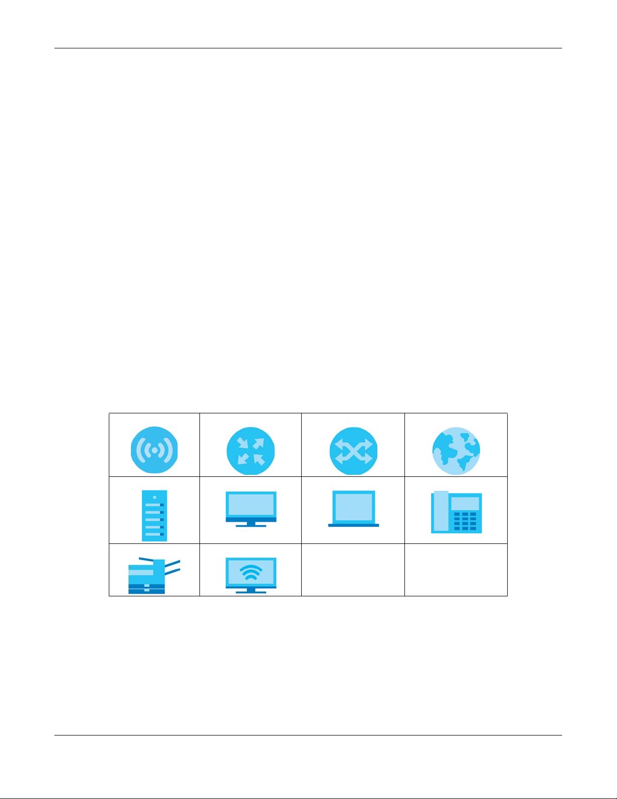
Icons Used in Figures
Figures in this guide may use the following generic icons. The Zyxel Device icon is not an exact
representation of your device.
Zyxel Device Router Switch Internet
Server Desktop Laptop IP Phone
Printer Smart T.V.
NWA50AX/NWA90AX/NWA55AXE Series User’s Guide
3
Page 4

Contents Overview
Contents Overview
Introduction ........................................................................................................................................... 12
AP Management .................................................................................................................................. 20
Hardware ............................................................................................................................................... 28
Web Configurator ................................................................................................................................. 31
Standalone Configuration ................................................................................................................42
Standalone Configuration ................................................................................................................... 43
Dashboard ............................................................................................................................................ 45
Setup Wizard ......................................................................................................................................... 51
Monitor ................................................................................................................................................... 56
Network ................................................................................................................................................. 69
Wireless ................................................................................................................................................... 76
User ......................................................................................................................................................... 88
AP Profile ................................................................................................................................................ 95
WDS Profile ........................................................................................................................................... 128
Certificates .......................................................................................................................................... 130
System .................................................................................................................................................. 146
Log and Report ................................................................................................................................... 165
File Manager ....................................................................................................................................... 177
Diagnostics .......................................................................................................................................... 188
LEDs ...................................................................................................................................................... 190
Reboot ................................................................................................................................................. 193
Shutdown ............................................................................................................................................. 194
Local Configuration in Cloud Mode ..............................................................................................195
Cloud Mode ........................................................................................................................................ 196
Network ............................................................................................................................................... 199
Maintenance ...................................................................................................................................... 202
Appendices and Troubleshooting .................................................................................................207
Troubleshooting .................................................................................................................................. 208
NWA50AX/NWA90AX/NWA55AXE Series User’s Guide
4
Page 5

Table of Contents
Table of Contents
Document Conventions ... .... .... ........................................................................................ .... ... ............3
Contents Overview .............................................................................................................................4
Table of Contents.................................................................................................................................5
Chapter 1
Introduction ........................................................................................................................................12
1.1 Overview ......................................................................................................................................... 12
1.2 Zyxel Device Roles .......................................................................................................................... 12
1.2.1 Root AP ................................................................................................................................... 14
1.2.2 Wireless Repeater .................................................................................................................. 14
1.2.3 Radio Frequency (RF) Monitor .............................................................................................15
1.3 Sample Feature Applications ........................................................................................................ 16
1.3.1 MBSSID .................................................................................................................................... 16
1.3.2 Dual-Radio ............................................................................................................................. 17
1.4 Zyxel Device Product Feature ....................................................................................................... 18
Chapter 2
AP Management................................................................................................................................20
2.1 Management Mode ...................................................................................................................... 20
2.1.1 Standalone ............................................................................................................................ 20
2.1.2 Nebula Control Center ......................................................................................................... 20
2.2 Switching Management Modes ................................................................................................... 22
2.3 Zyxel One Network (ZON) Utility .................................................................................................... 22
2.3.1 Requirements ......................................................................................................................... 22
2.3.2 Run the ZON Utility ................................................................................................................. 23
2.4 Ways to Access the Zyxel Device ................................................................................................. 26
2.5 Good Habits for Managing the Zyxel Device ............................................................................. 27
Chapter 3
Hardware............................................................................................................................................28
3.1 Zyxel Device Single LED .................................................................................................................. 28
3.1.1 Zyxel Device LED ................................................................................................................... 28
Chapter 4
Web Configurator...............................................................................................................................31
4.1 Overview ......................................................................................................................................... 31
4.2 Accessing the Web Configurator ................................................................................................. 31
4.3 Navigating the Web Configurator ............................................................................................... 34
NWA50AX/NWA90AX/NWA55AXE Series User’s Guide
5
Page 6

Table of Contents
4.3.1 Title Bar ................................................................................................................................... 35
4.3.2 Navigation Panel .................................................................................................................. 36
4.3.3 Standalone Mode Navigation Panel Menus ..................................................................... 36
4.3.4 Cloud Mode Navigation Panel Menus ............................................................................... 38
4.3.5 Tables and Lists ...................................................................................................................... 39
Part I: Standalone Configuration...................................................................42
Chapter 5
Standalone Configuration.................................................................................................................43
5.1 Overview ......................................................................................................................................... 43
5.2 Starting and Stopping the Zyxel Device ...................................................................................... 43
Chapter 6
Dashboard..........................................................................................................................................45
6.1 Overview ......................................................................................................................................... 45
6.1.1 CPU Usage ............................................................................................................................. 48
6.1.2 Memory Usage ...................................................................................................................... 49
Chapter 7
Setup Wizard.......................................................................................................................................51
7.1 Accessing the Wizard ..................................................................................................................... 51
7.2 Using the Wizard ............................................................................................................................. 51
7.2.1 Step 1 Time Settings .............................................................................................................. 51
7.2.2 Step 2 Password and Uplink Connection ........................................................................... 52
7.2.3 Step 3 Radio .......................................................................................................................... 53
7.2.4 Step 4 SSID .............................................................................................................................. 54
7.2.5 Summary ................................................................................................................................ 55
Chapter 8
Monitor................................................................................................................................................56
8.1 Overview ......................................................................................................................................... 56
8.1.1 What You Can Do in this Chapter ....................................................................................... 56
8.2 What You Need to Know ............................................................................................................... 56
8.3 Network Status ................................................................................................................................ 57
8.3.1 Port Statistics Graph .............................................................................................................. 58
8.4 Radio List .......................................................................................................................................... 59
8.4.1 AP Mode Radio Information ................................................................................................61
8.5 Station List ........................................................................................................................................ 62
8.6 WDS Link Info ................................................................................................................................... 63
8.7 Detected Device ............................................................................................................................ 64
NWA50AX/NWA90AX/NWA55AXE Series User’s Guide
6
Page 7

Table of Contents
8.8 View Log .......................................................................................................................................... 66
Chapter 9
Network...............................................................................................................................................69
9.1 Overview ......................................................................................................................................... 69
9.1.1 What You Can Do in this Chapter ....................................................................................... 69
9.2 IP Setting .......................................................................................................................................... 69
9.3 VLAN ................................................................................................................................................ 71
9.4 NCC Discovery ................................................................................................................................ 74
Chapter 10
Wireless...............................................................................................................................................76
10.1 Overview ....................................................................................................................................... 76
10.1.1 What You Can Do in this Chapter ..................................................................................... 76
10.1.2 What You Need to Know ...................................................................................................77
10.2 AP Management .......................................................................................................................... 77
10.3 Rogue AP ....................................................................................................................................... 82
10.3.1 Add/Edit Rogue/Friendly List .............................................................................................. 85
10.4 DCS ................................................................................................................................................ 86
10.5 Technical Reference .................................................................................................................... 86
Chapter 11
User......................................................................................................................................................88
11.1 Overview ....................................................................................................................................... 88
11.1.1 What You Can Do in this Chapter ..................................................................................... 88
11.1.2 What You Need To Know ...................................................................................................88
11.2 User Summary ................................................................................................................................ 89
11.2.1 Add/Edit User ....................................................................................................................... 89
11.3 Setting ............................................................................................................................................ 91
11.3.1 Edit User Authentication Timeout Settings ........................................................................ 93
Chapter 12
AP Profile.............................................................................................................................................95
12.1 Overview ....................................................................................................................................... 95
12.1.1 What You Can Do in this Chapter ..................................................................................... 95
12.1.2 What You Need To Know ...................................................................................................95
12.2 Radio .............................................................................................................................................. 96
12.2.1 Add/Edit Radio Profile ........................................................................................................ 97
12.3 SSID ............................................................................................................................................... 102
12.3.1 SSID List ............................................................................................................................... 103
12.3.2 Add/Edit SSID Profile ......................................................................................................... 104
12.4 Security List .................................................................................................................................. 107
12.4.1 Add/Edit Security Profile ................................................................................................... 107
NWA50AX/NWA90AX/NWA55AXE Series User’s Guide
7
Page 8

Table of Contents
12.5 MAC Filter List .............................................................................................................................. 124
12.5.1 Add/Edit MAC Filter Profile ............................................................................................... 124
12.6 Layer-2 Isolation List .................................................................................................................... 125
12.6.1 Add/Edit Layer-2 Isolation Profile .................................................................................... 127
Chapter 13
WDS Profile........................................................................................................................................128
13.1 Overview ..................................................................................................................................... 128
13.1.1 What You Can Do in this Chapter ................................................................................... 128
13.2 WDS Profile ................................................................................................................................... 128
13.2.1 Add/Edit WDS Profile ........................................................................................................ 129
Chapter 14
Certificates .......................................................................................................................................130
14.1 Overview ..................................................................................................................................... 130
14.1.1 What You Can Do in this Chapter ................................................................................... 130
14.1.2 What You Need to Know ................................................................................................. 130
14.1.3 Verifying a Certificate ...................................................................................................... 132
14.2 My Certificates ............................................................................................................................ 133
14.2.1 Add My Certificates .......................................................................................................... 134
14.2.2 Edit My Certificates ........................................................................................................... 136
14.2.3 Import Certificates ............................................................................................................ 139
14.3 Trusted Certificates ..................................................................................................................... 140
14.3.1 Edit Trusted Certificates .................................................................................................... 141
14.3.2 Import Trusted Certificates ............................................................................................... 144
14.4 Technical Reference .................................................................................................................. 145
Chapter 15
System...............................................................................................................................................146
15.1 Overview ..................................................................................................................................... 146
15.1.1 What You Can Do in this Chapter ................................................................................... 146
15.2 Host Name ................................................................................................................................... 146
15.3 Date and Time ........................................................................................................................... 147
15.3.1 Pre-defined NTP Time Servers List ..................................................................................... 149
15.3.2 Time Server Synchronization ............................................................................................ 150
15.4 WWW Overview .......................................................................................................................... 151
15.4.1 Service Access Limitations ............................................................................................... 151
15.4.2 System Timeout .................................................................................................................. 151
15.4.3 HTTPS ................................................................................................................................... 151
15.4.4 Configuring WWW Service Control ................................................................................. 152
15.4.5 HTTPS Example ................................................................................................................... 153
15.5 SSH ................................................................................................................................................ 159
15.5.1 How SSH Works .................................................................................................................. 160
NWA50AX/NWA90AX/NWA55AXE Series User’s Guide
8
Page 9

Table of Contents
15.5.2 SSH Implementation on the Zyxel Device ...................................................................... 161
15.5.3 Requirements for Using SSH ..............................................................................................161
15.5.4 Configuring SSH ................................................................................................................. 161
15.5.5 Examples of Secure Telnet Using SSH .............................................................................. 162
15.6 FTP ............................................................................................................................................... 163
Chapter 16
Log and Report....... .... ... ............................................. ... .... .... ...........................................................165
16.1 Overview ..................................................................................................................................... 165
16.1.1 What You Can Do In this Chapter .................................................................................. 165
16.2 Email Daily Report ....................................................................................................................... 165
16.3 Log Setting ................................................................................................................................... 167
16.3.1 Log Setting Screen ............................................................................................................ 168
16.3.2 Edit System Log Settings ................................................................................................... 169
16.3.3 Edit Remote Server ............................................................................................................ 173
16.3.4 Active Log Summary ........................................................................................................ 174
Chapter 17
File Manager ....................................................................................................................................177
17.1 Overview ..................................................................................................................................... 177
17.1.1 What You Can Do in this Chapter ................................................................................... 177
17.1.2 What you Need to Know .................................................................................................. 177
17.2 Configuration File ....................................................................................................................... 178
17.2.1 Example of Configuration File Download Using FTP ...................................................... 182
17.3 Firmware Package ..................................................................................................................... 183
17.3.1 Example of Firmware Upload Using FTP .......................................................................... 184
17.4 Shell Script .................................................................................................................................... 185
Chapter 18
Diagnostics.......................................................................................................................................188
18.1 Overview ..................................................................................................................................... 188
18.1.1 What You Can Do in this Chapter ................................................................................... 188
18.2 Diagnostics .................................................................................................................................. 188
18.3 Remote Capture ........................................................................................................................ 189
Chapter 19
LEDs ...................................................................................................................................................190
19.1 Overview ..................................................................................................................................... 190
19.1.1 What You Can Do in this Chapter ................................................................................... 190
19.2 Suppression Screen .................................................................................................................... 190
19.3 Locator Screen ........................................................................................................................... 191
Chapter 20
Reboot...............................................................................................................................................193
NWA50AX/NWA90AX/NWA55AXE Series User’s Guide
9
Page 10

Table of Contents
20.1 Overview ..................................................................................................................................... 193
20.1.1 What You Need To Know ................................................................................................. 193
20.2 Reboot ......................................................................................................................................... 193
Chapter 21
Shutdown..........................................................................................................................................194
21.1 Overview ..................................................................................................................................... 194
21.1.1 What You Need To Know ................................................................................................. 194
21.2 Shutdown ..................................................................................................................................... 194
Part II: Local Configuration in Cloud Mode................................................ 195
Chapter 22
Cloud Mode .....................................................................................................................................196
22.1 Overview ..................................................................................................................................... 196
22.2 Cloud Mode Web Configurator Screens ................................................................................. 196
22.3 Dashboard .................................................................................................................................. 197
Chapter 23
Network.............................................................................................................................................199
23.1 Overview ..................................................................................................................................... 199
23.1.1 What You Can Do in this Chapter ................................................................................... 199
23.2 IP Setting ...................................................................................................................................... 199
23.3 VLAN ............................................................................................................................................ 201
Chapter 24
Maintenance....................................................................................................................................202
24.1 Overview ..................................................................................................................................... 202
24.1.1 What You Can Do in this Chapter ................................................................................... 202
24.2 Shell Script .................................................................................................................................... 202
24.3 Diagnostics .................................................................................................................................. 203
24.4 View Log ...................................................................................................................................... 204
Part III: Appendices and Troubleshooting..................................................207
Chapter 25
Troubleshooting................................................................................................................................208
25.1 Overview ..................................................................................................................................... 208
25.2 Power, Hardware Connections, and LED ................................................................................ 208
25.3 Zyxel Device Management, Access, and Login ..................................................................... 209
NWA50AX/NWA90AX/NWA55AXE Series User’s Guide
10
Page 11

Table of Contents
25.4 Internet Access ........................................................................................................................... 212
25.5 WiFi Network ................................................................................................................................ 213
25.6 Resetting the Zyxel Device ........................................................................................................ 215
25.7 Getting More Troubleshooting Help .........................................................................................215
Appendix A Importing Certificates ............................................................................................... 216
Appendix B IPv6............................................................................................................................... 240
Appendix C Customer Support ..................................................................................................... 248
Appendix D Legal Information ...................................................................................................... 253
Index.................................................................................................................................................261
NWA50AX/NWA90AX/NWA55AXE Series User’s Guide
11
Page 12

1.1 Overview
This User’s Guide covers the models listed below:
• NWA50AX
• NWA90AX
• NWA55AXE
The Zyxel Device can be managed in one of the following methods: remote management through
Nebula Control Center (NCC) or local management in Standalone Mode. The Zyxel Device runs in
standalone mode by default, but it is recommended to use NCC management if it is available for your
device. For more information about Access Point (AP) management, see Section 2.1 on page 20.
Use the Zyxel Device to set up a wireless network with other IEEE 802.11a/b/g/n/ac/ax compatible
devices in either 2.4 GHz and 5 GHz networks or both at the same time.
CHAPTER 1
Introduction
When two or more APs are interconnected, this network is called a Wireless Distribution System (WDS).
See Section 1.2.2 on page 14 for more information on root and repeater APs and how to set them up.
The screens you see in the web configurator may be different depending on the Zyxel Device model
you’re using.
1.2 Zyxel Device Roles
This section describes some of the different roles that your Zyxel Device can take up within a network.
Not all roles are supported by all models (see Section 1.4 on page 18). The Zyxel Device can serve as a:
• Access Point (AP) - This is used to allow wireless clients to connect to the Internet.
• Radio Frequency (RF) monitor - An RF monitor searches for rogue APs to help eliminate network
threats if it supports rogue APs detection/containment. An RF monitor cannot simultaneously act as
an AP.
• Root AP - A root AP connects to the gateway or switch through a wired Ethernet connection and
has wireless repeaters connected to it to extend its range.
• Wireless repeater - A wireless repeater wirelessly connects to a root AP and extends the network’s
wireless range.
If a client (D) tries to set up his own AP (R) with weak security settings, the network becomes exposed to
threats. The RF monitor (M) scans the area to detect all APs, which can help the network administrator
discover these rogue APs.
NWA50AX/NWA90AX/NWA55AXE Series User’s Guide
12
Page 13
Chapter 1 Introduction
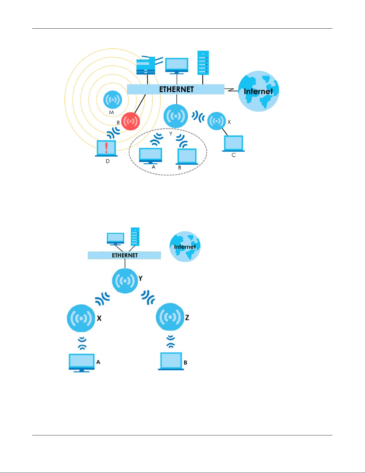
Figure 1 Zyxel Device Application in a Network
The following figure shows you how to create a secure Wireless Distribution System (WDS). The root AP (Y)
is connected to a network with Internet access and has wireless repeaters (X and Z) connected to it to
expand the wireless network’s range. Clients (A and B) can access the wired network through the
wireless repeaters (X and Z) and/or root AP.
Figure 2 Wireless Distribution System Network Example
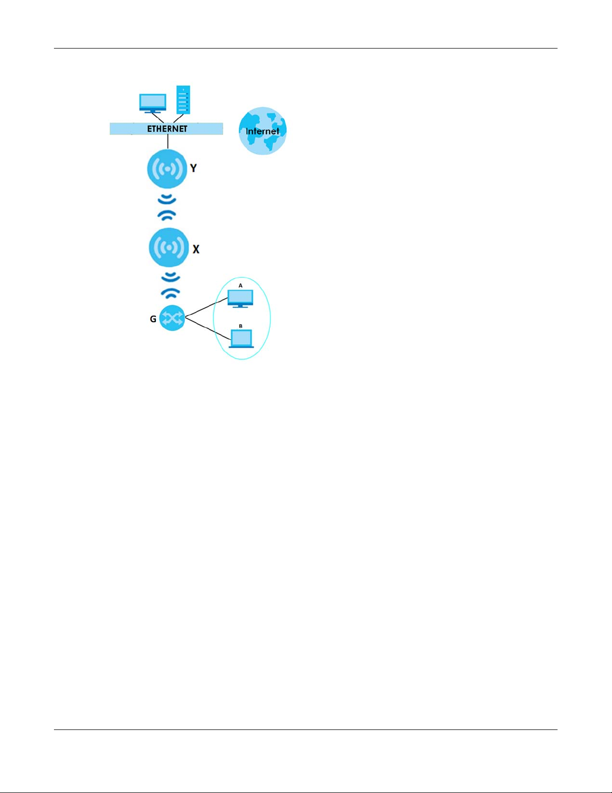
The following figure shows an example of a wireless bridge network. The root AP (Y) is connected to a
network with Internet access and has a wireless repeater (X) connected to it to expand the wireless
network’s range. Clients (A and B) are connected to the wired network through the gateway (G). They
can access the wired network through the wireless repeater and/or root AP.
NWA50AX/NWA90AX/NWA55AXE Series User’s Guide
13
Page 14
Chapter 1 Introduction
Figure 3 Wireless Bridge Network Example
1.2.1 Root AP
In Root AP mode, you can have multiple SSIDs active for regular wireless connections and one SSID for
the connection with a repeater (repeater SSID). Wireless clients can use either SSID to associate with the
Zyxel Device in Root AP mode. A repeater must use the repeater SSID to connect to the Zyxel Device in
Root AP mode.
When the Zyxel Device is in Root AP mode, repeater security between the Zyxel Device and other
repeaters is independent of the security between the wireless clients and the AP or repeater. When
repeater security is enabled, both APs and repeaters must use the same pre-shared key. See Section
10.2 on page 77 and Section 13.2 on page 128 for more details.
Unless specified, the term “security settings” refers to the traffic between the wireless clients and the AP.
At the time of writing, repeater security is compatible with the Zyxel Device only.
1.2.2 Wireless Repeater
Using Repeater mode, your Zyxel Device can extend the range of the WLAN. In the figure below, the
Zyxel Device in Repeater mode (Z) has a wireless connection to the Zyxel Device in Root AP mode (X)
which is connected to a wired network and also has a wireless connection to another Zyxel Device in
Repeater mode (Y) at the same time. Z and Y act as repeaters that forward traffic between associated
wireless clients and the wired LAN. Clients A and B access the AP and the wired network behind the AP
through repeaters Z and Y.
NWA50AX/NWA90AX/NWA55AXE Series User’s Guide
14
Page 15
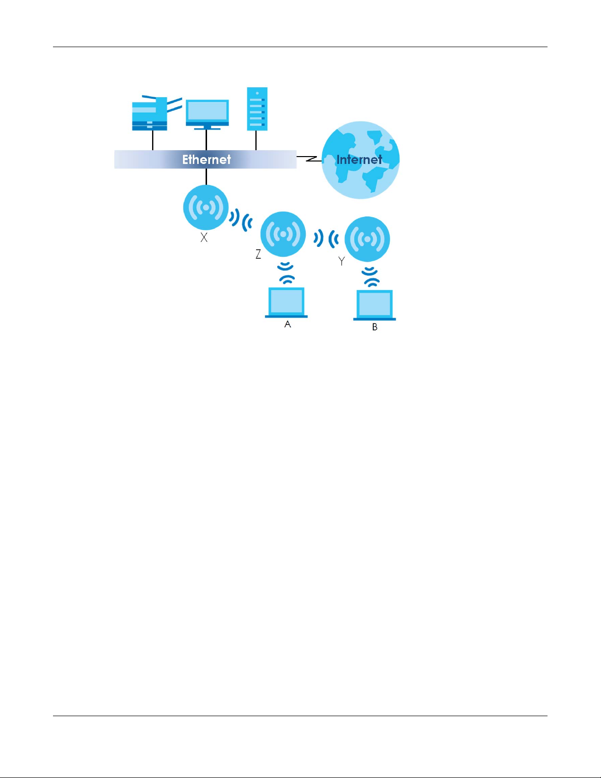
Figure 4 Repeater Application
Chapter 1 Introduction
When the Zyxel Device is in Repeater mode, repeater security between the Zyxel Device and other
repeater is independent of the security between the wireless clients and the AP or repeater. When
repeater security is enabled, both APs and repeaters must use the same pre-shared key. See Section
10.2 on page 77 and Section 13.2 on page 128 for more details.
For NCC managed devices, you only need to enable AP Smart Mesh to automatically create wireless
links between APs. See the NCC User’s Guide for more details.
To set up a WDS in standalone mode APs, do the following steps. You should already have the root AP
set up (see the Quick Start Guide for hardware connections).
1 Go to Configuration > Object > WDS Profile in your root AP Web Configurator and click Add.
2 Enter a profile name, an SSID for the WDS, and a pre-shared key.
3 Do steps 1 and 2 for the wireless repeater using the same SSID and pre-shared key.
4 Once the security settings of peer sides match one another, the connection between the root and
repeater Zyxel Devices is made.
Note: Frequency bands 5250-5350 MHz and 5470-5725 MHz are not supported in Repeater
mode.
1.2.3 Radio Frequency (RF) Monitor
The Zyxel Device can be set to work as an RF monitor to discover nearby Access Points. The information
it obtains from other APs is used to tag possible rogue APs.
The models that do not support MON Mode support Rogue AP Detection (see Section 10.3 on page 82).
Rogue AP Detection allows the AP to scan all channels similar to MON Mode except that the Zyxel
NWA50AX/NWA90AX/NWA55AXE Series User’s Guide
15
Page 16

Chapter 1 Introduction
Device still works as an AP while it scans the environment for wireless signals. To see which Zyxel Devices
support the RF Monitor feature, see Section 1.4 on page 18.
1.3 Sample Feature Applications
This section describes some possible scenarios and topologies that you can set up using your Zyxel
Device.
1.3.1 MBSSID
A Basic Service Set (BSS) is the set of devices forming a single wireless network (usually an access point
and one or more wireless clients). The Service Set IDentifier (SSID) is the name of a BSS. In Multiple BSS
(MBSSID) mode, the Zyxel Device provides multiple virtual APs, each forming its own BSS and using its
own individual SSID profile.
You can configure multiple SSID profiles, and have all of them active at any one time.
You can assign different wireless and security settings to each SSID profile. This allows you to
compartmentalize groups of users, set varying access privileges, and prioritize network traffic to and
from certain BSSs.
To the WiFi clients in the network, each SSID appears to be a different access point. As in any WiFi
network, clients can associate only with the SSIDs for which they have the correct security settings.
For example, you might want to set up a WiFi network in your office where Internet telephony (VoIP)
users have priority. You also want a regular WiFi network for standard users, as well as a ‘guest’ WiFi
network for visitors. In the following figure, VoIP_SSID users have QoS priority, SSID01 is the WiFi network for
standard users, and Guest_SSID is the WiFi network for guest users. In this example, the guest user is
forbidden access to the wired Local Area Network (LAN) behind the AP and can access only the
Internet.
NWA50AX/NWA90AX/NWA55AXE Series User’s Guide
16
Page 17
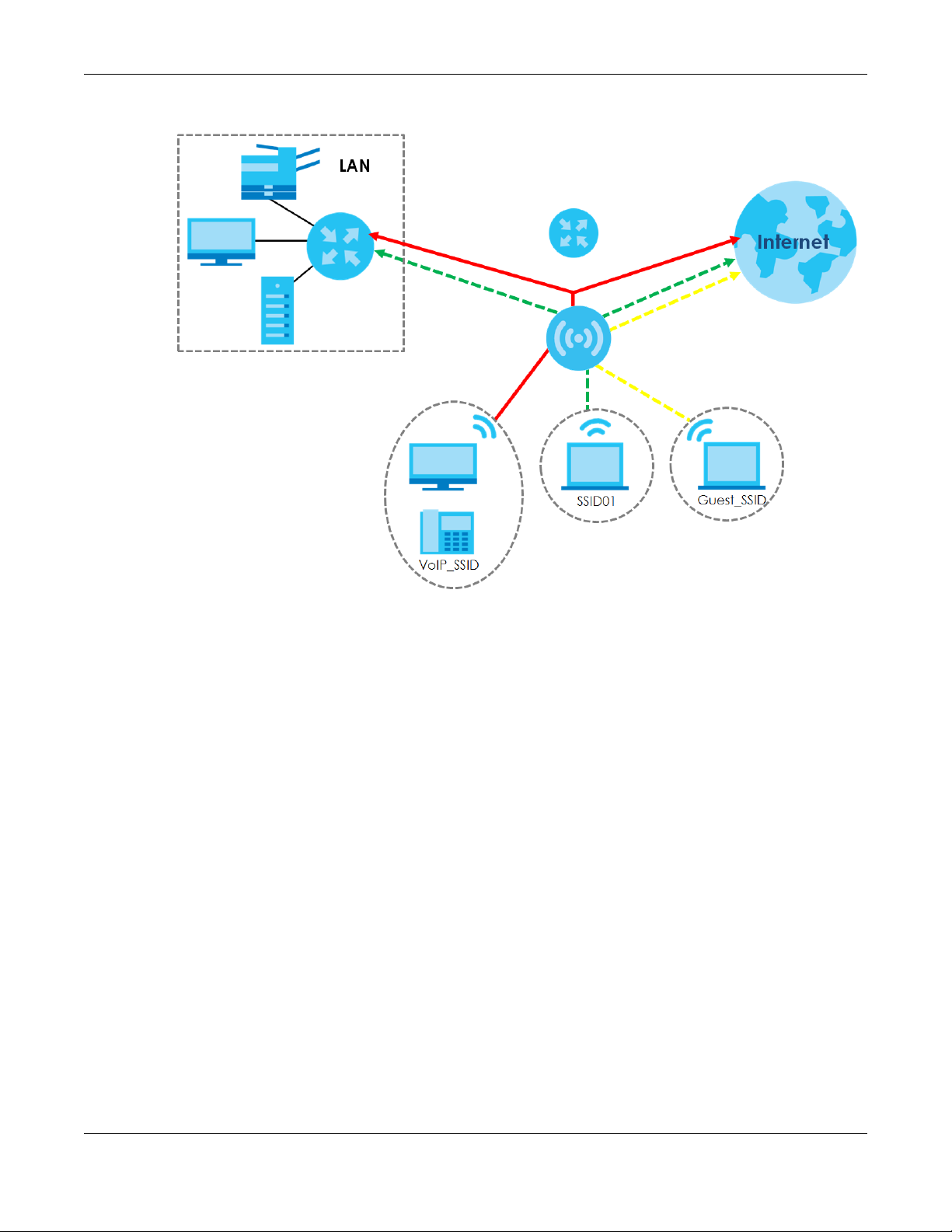
Figure 5 Multiple BSSs
Chapter 1 Introduction
1.3.2 Dual-Radio
Some of the Zyxel Device models are equipped with dual wireless radios. This means you can configure
two different wireless networks to operate simultaneously.
Note: A different channel should be configured for each WLAN interface to reduce the
effects of radio interference.
You could use the 2.4 GHz band for regular Internet surfing and downloading while using the 5 GHz
band for time sensitive traffic like high-definition video, music, and gaming.
NWA50AX/NWA90AX/NWA55AXE Series User’s Guide
17
Page 18
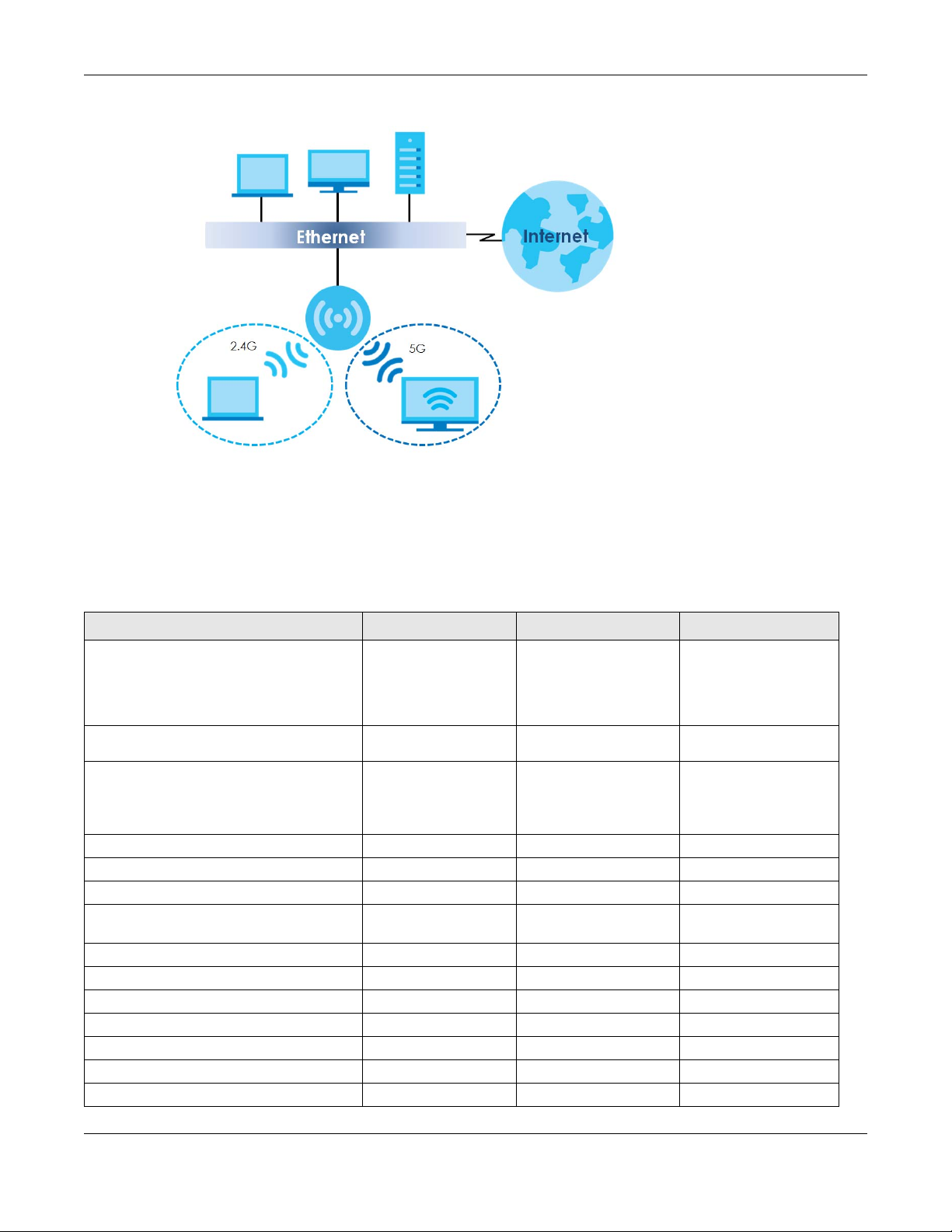
Figure 6 Dual-Radio Application
Chapter 1 Introduction
1.4 Zyxel Device Product Feature
The following table lists the features of the Zyxel Device.
Table 1 Zyxel Device Product Feature Table
FEATURES NWA50AX NWA90AX NWA55AXE
Supported Wireless Standards
Supported Frequency Bands 2.4 GHz
Available Security Modes None
Number of SSID Profiles 64 64 64
Number of Wireless Radios 2 2 2
Rogue AP Detection Yes Yes Yes
WDS (Wireless Distribution System) - Root AP
& Repeater Modes
Layer-2 Isolation No Yes No
Supported PoE Standards
Power Detection No No No
External Antennas No No Yes
Internal Antennas Yes Yes No
Console Port 4-Pin Serial 4-Pin Serial No
Reset button Yes Yes No
IEEE 802.11a
IEEE802.11b
IEEE 802.11g
IEEE 802.11n
IEEE 802.11ac
IEEE802.11ax
5 GHz
Enhanced-open
WEP
WPA2-MIX-Personal
WPA3-Personal
Yes Yes Yes
IEEE 802.3at IEEE 802.3at IEEE 802.3at
IEEE 802.11a
IEEE802.11b
IEEE 802.11g
IEEE 802.11n
IEEE 802.11ac
IEEE802.11ax
2.4 GHz
5 GHz
None
Enhanced-open
WEP
WPA2-MIX / WPA3 -
Personal & Enterprise
IEEE 802.11a
IEEE802.11b
IEEE 802.11g
IEEE 802.11n
IEEE 802.11ac
IEEE802.11ax
Enhanced-open
WPA2-MIX-Personal
WPA3-Personal
2.4 GHz
5 GHz
None
WEP
NWA50AX/NWA90AX/NWA55AXE Series User’s Guide
18
Page 19

Chapter 1 Introduction
Table 1 Zyxel Device Product Feature Table (continued)
FEATURES NWA50AX NWA90AX NWA55AXE
LED Locator Yes Yes No
LED Suppression Yes Yes Yes
AC (AP Controller) Discovery No No No
NCC Discovery Yes Yes Yes
802.11r Fast Roaming Support Yes Yes Yes
802.11k/v Assisted Roaming Yes Yes Yes
Ethernet Storm Control No No No
Wireless Bridge VLAN ID No No Yes
Grounding No No No
Power Jack Yes Yes No
Maximum number of log messages 512 event logs 512 event logs 512 event logs
Firmware Version 6.25 6.27 6.25
NWA50AX/NWA90AX/NWA55AXE Series User’s Guide
19
Page 20

2.1 Management Mode
The Zyxel Device is a unified AP and can be managed by the NCC or work as a standalone device. We
recommend you use NCC to manage multiple APs (see the NCC User’s Guide).
Note: Not all models can be managed by NCC or an AC. See Section 1.4 on page 18 to
check whether your product supports these.
The following table shows the default IP addresses and firmware upload methods for different
management modes.
Table 2 Zyxel Device Management Mode Comparison
MANAGEMENT MODE DEFAULT IP ADDRESS UPLOAD FIRMWARE VIA
Nebula Control Center Dynamic NCC Portal
Standalone Dynamic or
Static (192.168.1.2)
CHAPTER 2
AP Management
Built-in Web Configurator
When the Zyxel Device is in standalone mode and connects to a DHCP server, it uses the IP address
assigned by the DHCP server. Otherwise, the Zyxel Device uses the default static management IP
address (192.168.1.2). You can use the NCC Discovery screen to allow the Zyxel Device to be managed
by the NCC.
When the Zyxel Device is managed by the NCC, it acts as a DHCP client and obtains an IP address from
the NCC. It can be configured ONLY by the NCC. To change the Zyxel Device back to standalone
mode, use the Reset button to restore the default configuration. Alternatively, you need to check the
NCC for the Zyxel Device’s IP address and use FTP to upload the default configuration file at conf/
system-default.conf to the Zyxel Device and reboot the device.
2.1.1 Standalone
When working in standalone mode, the Zyxel Device is configured mainly with its built-in Web
Configurator. You can only connect to and set up one Zyxel Device at a time in this mode.
See Chapter 5 on page 43 for detailed information about the standalone Web Configurator screens.
2.1.2 Nebula Control Center
In this mode, which is also called cloud mode, you can manage and monitor the Zyxel Device through
the Zyxel Nebula cloud-based network management system. This means you can manage devices
remotely without the need of connecting to each device directly. It offers many features to better
manage and monitor not just the Zyxel Device, but your network as a whole, including supported
switches and gateways. Your network can also be managed through your smartphone using the
Nebula Mobile app. See Section on page 196 for an example NCC managed network topology.
NWA50AX/NWA90AX/NWA55AXE Series User’s Guide
20
Page 21
Chapter 2 AP Management
NCC allows different levels of management. You can configure each device on its own or configure a
set of devices together as a site. You can also monitor groups of sites called organizations, as shown
below.
Table 3 NCC Management Levels
Organization
Site A Site B
Device A-1 Device A-2 Device B-1 Device B-2
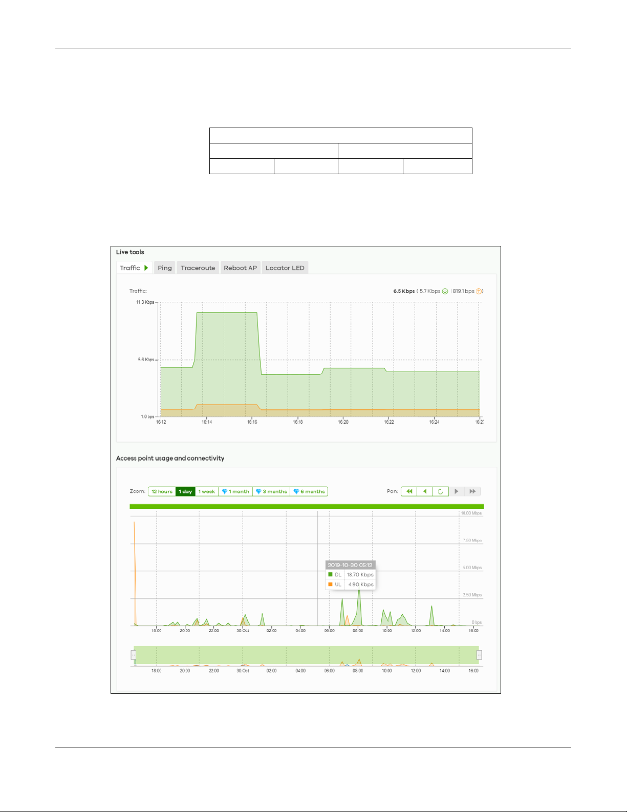
It graphically presents your device/network statistics and shows an overview of your network topology,
as shown in the following figure. It also sends reports, alerts, and notifications for events, such as when a
site goes offline.
Figure 7 Traffic Monitoring Graph From NCC
NWA50AX/NWA90AX/NWA55AXE Series User’s Guide
21
Page 22

Chapter 2 AP Management
See the NCC (Nebula Control Center) User’s Guide for how to configure Nebula managed devices. See
Chapter 23 on page 199 if you want to change the Zyxel Device’s VLAN setting or manually set its IP
address.
Note: Make sure your network firewall allows TCP ports 443, 4335, and 6667 as well as UDP port
123 so the device can connect to and sync with the NCC.
2.2 Switching Management Modes
The Zyxel Device is in standalone mode by default, with NCC discovery enabled.
Standalone-to-NCC
Register the Zyxel Device at the NCC website and then turn on the Zyxel Device. Make sure that NCC
Discovery is enabled (see Section 9.4 on page 74). The NCC manages the Zyxel Device automatically
when it is discovered.
NCC-to-Standalone
Unregister the Zyxel Device from the NCC organization/site. Reset the Zyxel Device to factory defaults
(see Section 25.6 on page 215).
2.3 Zyxel One Network (ZON) Utility
ZON Utility is a program designed to help you deploy and manage a network more efficiently. It detects
devices automatically and allows you to do basic settings on devices in the network without having to
be near it.
The ZON Utility issues requests via Zyxel Discovery Protocol (ZDP) and in response to the query, the device
responds back with basic information including IP address, firmware version, location, system and model
name in the same broadcast domain. The information is then displayed in the ZON Utility screen and you
can perform tasks like basic configuration of the devices and batch firmware upgrade in it. You can
download the ZON Utility at www.zyxel.com and install it on your computer (Windows operating system).
2.3.1 Requirements
Before installing the ZON Utility on your PC, please make sure it meets the requirements listed below.
Operating System
At the time of writing, the ZON Utility is compatible with:
• Windows 7 (both 32-bit / 64-bit versions)
• Windows 8 (both 32-bit / 64-bit versions)
• Windows 8.1 (both 32-bit / 64-bit versions)
• Window 10 (both 32-bit / 64-bit versions)
NWA50AX/NWA90AX/NWA55AXE Series User’s Guide
22
Page 23
Note: To check for your Windows operating system version, right-click on My Computer >
Properties on your computer. You should see this information in the General tab.
Note: It is suggested that you install Npcap, the packet capture library for Windows operating
systems, and remove WinPcap or any other installed packet capture tools before you
install the ZON utility.
Hardware
Here are the minimum hardware requirements to use the ZON Utility on your PC.
• Core i3 processor
•2 GB RAM
• 100 MB free hard disk
• WXGA (Wide XGA 1280x800)
2.3.2 Run the ZON Utility
1 Double-click the ZON Utility to run it.
Chapter 2 AP Management
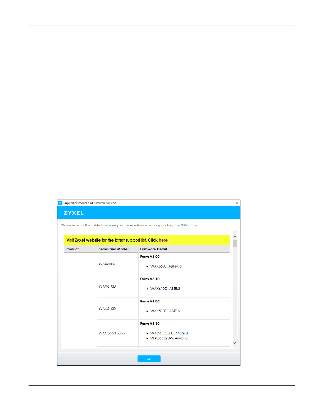
2 The first time you run the ZON Utility, you will see if your device and firmware version support the ZON
Utility. Click the OK button to close this screen.
Figure 8 Supported Devices and Versions
NWA50AX/NWA90AX/NWA55AXE Series User’s Guide
23
Page 24
Chapter 2 AP Management
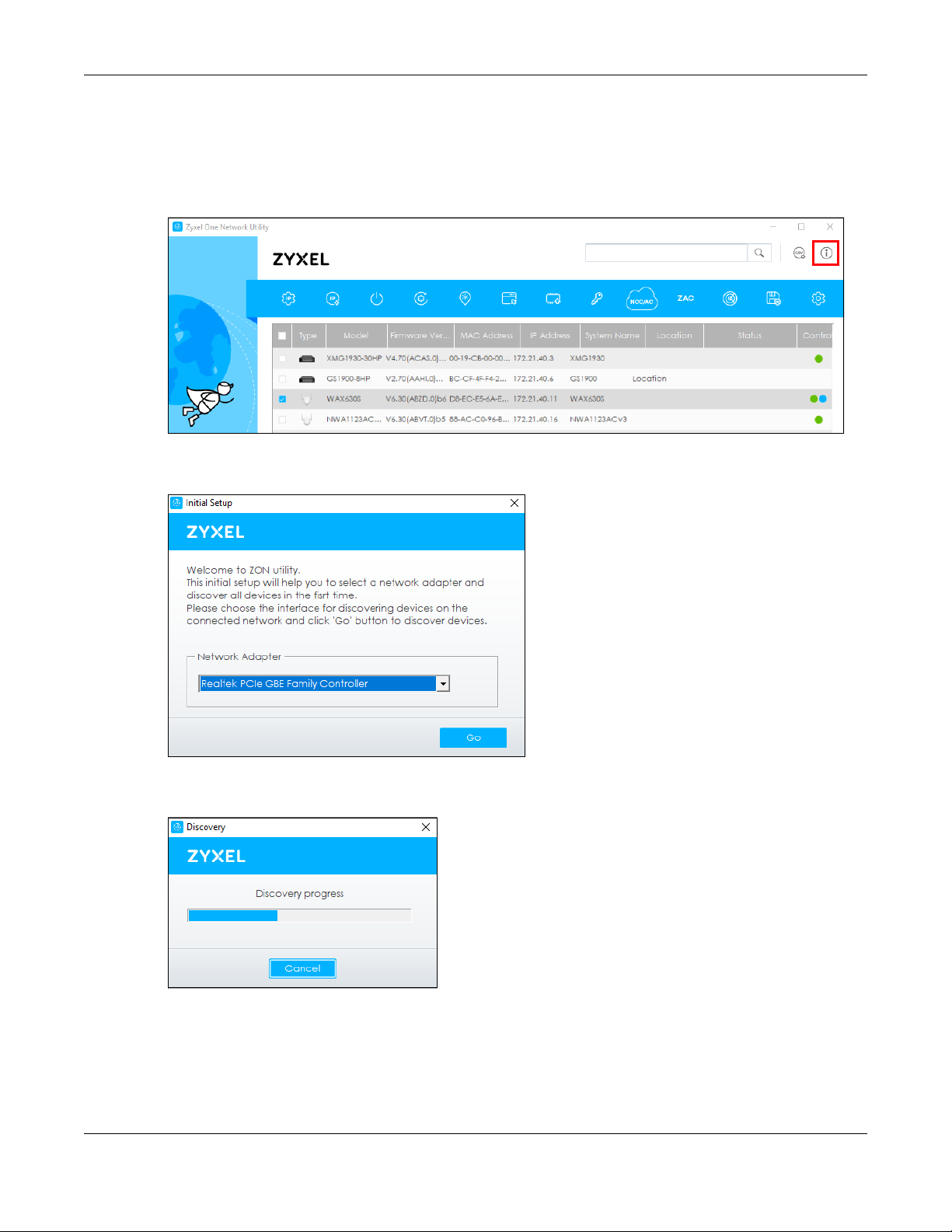
If you want to check the supported models and firmware versions later, you can click the Show
information about ZON icon in the upper right hand corner of the screen. Then select the Supported
model and firmware version link. If your device is not listed here, see the device release notes for ZON
Utility support. The release notes are in the firmware zip file on the Zyxel web site.
Figure 9 ZON Utility Screen
3 Select a network adapter to which your supported devices are connected.
Figure 10 Network Adapter
4 Click the Go button for the ZON Utility to discover all supported devices in your network.
Figure 11 Discovery
5 The ZON Utility screen shows the devices discovered.
NWA50AX/NWA90AX/NWA55AXE Series User’s Guide
24
Page 25
Chapter 2 AP Management
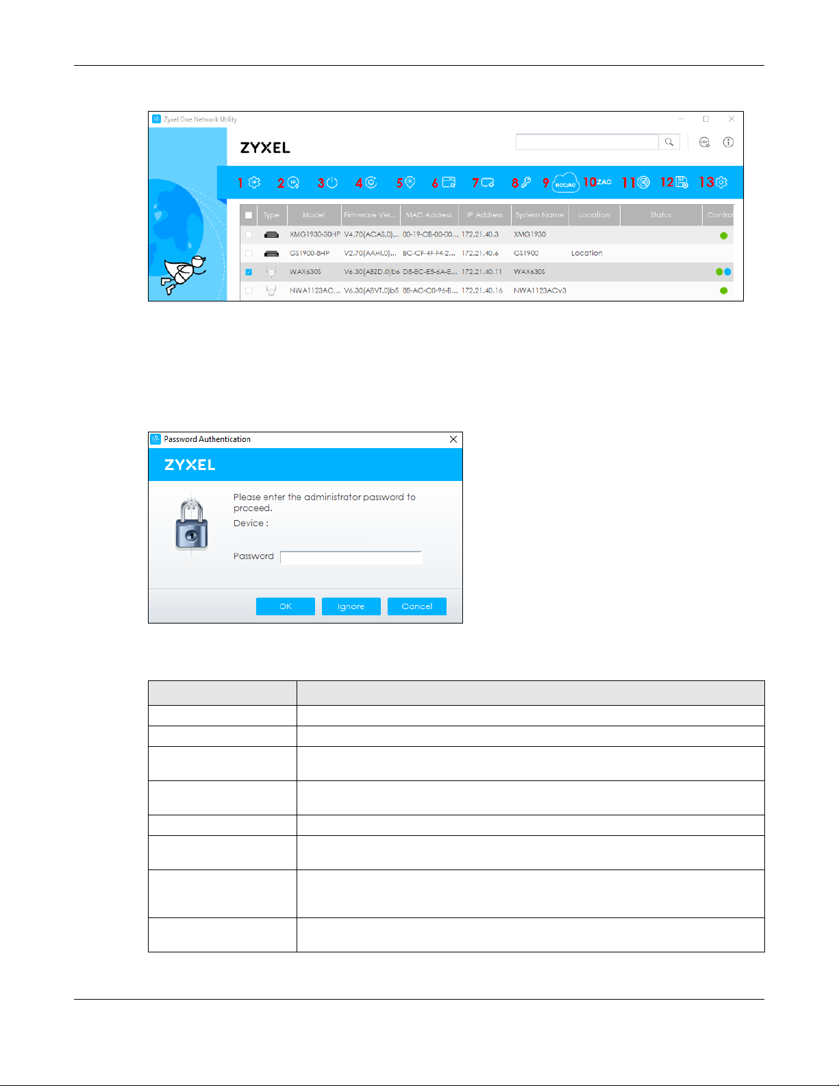
Figure 12 ZON Utility Screen
6 Select a device and then use the icons to perform actions. Some functions may not be available for
your devices.
Note: You must know the selected device admin password before taking actions on the
device using the ZON Utility icons.
Figure 13 Password Prompt
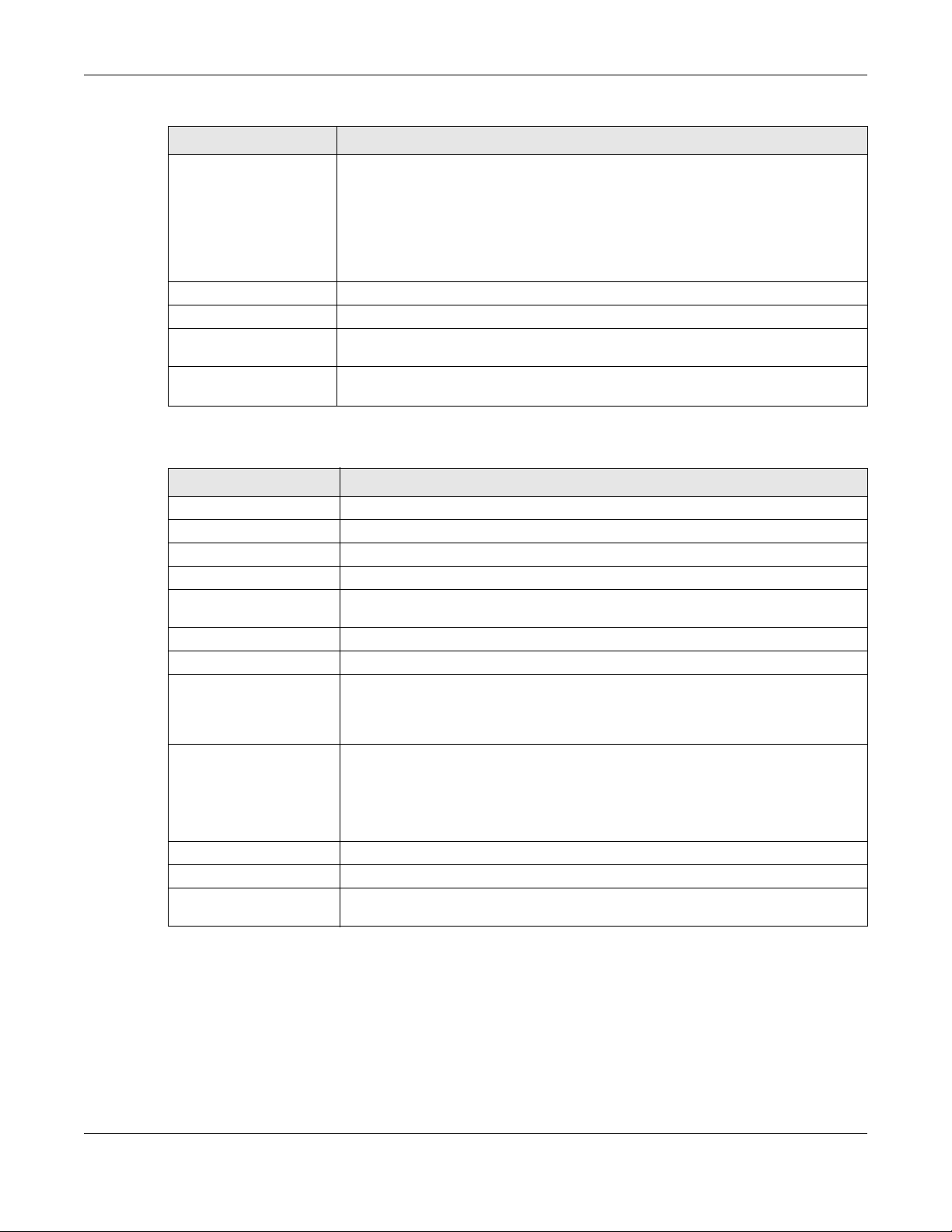
The following table describes the icons numbered from left to right in the ZON Utility screen.
Table 4 ZON Utility Icons
ICON DESCRIPTION
1 IP Configuration Change the selected device’s IP address.
2 Renew IP Address Update a DHCP-assigned dynamic IP address.
3 Reboot Device Use this icon to restart the selected device(s). This may be useful when troubleshooting
or upgrading new firmware.
4 Reset Configuration to
Default
5 Locator LED Use this icon to locate the selected device by causing its Locator LED to blink.
6 Web GUI Use this to access the selected device Web Configurator from your browser. You will
7 Firmware Upgrade Use this icon to upgrade new firmware to selected device(s) of the same model. Make
8 Change Password Use this icon to change the admin password of the selected device. You must know
Use this icon to reload the factory-default configuration file. This means that you will
lose all previous configurations.
need a username and password to log in.
sure you have downloaded the firmware from the Zyxel website to your computer and
unzipped it in advance.
the current admin password before changing to a new one.
NWA50AX/NWA90AX/NWA55AXE Series User’s Guide
25
Page 26
Chapter 2 AP Management
Table 4 ZON Utility Icons (continued)
ICON DESCRIPTION
9 Configure NCC
Discovery
10 ZAC Use this icon to run the Zyxel AP Configurator of the selected AP.
11 Clear and Rescan Use this icon to clear the list and discover all devices on the connected network again.
12 Save Configuration Use this icon to save configuration changes to permanent memory on a selected
13 Settings Use this icon to select a network adapter for the computer on which the ZON utility is
The option is available if the selected device supports Nebula Control Center (NCC)
discovery. You must have Internet access to use this feature. Use this icon on the
selected device to enable or disable the Nebula Control Center (NCC) discovery
feature.
If the feature is enabled, the selected device will try to connect to the NCC. If the
selected device has successfully connected to the NCC and is registered on the NCC,
it will change to the Nebula cloud mode.
device.
installed, and the utility language.
The following table describes the fields in the ZON Utility main screen.
Table 5 ZON Utility Fields
LABEL DESCRIPTION
Type This field displays an icon of the kind of device discovered.
Model This field displays the model name of the discovered device.
Firmware Version This field displays the firmware version of the discovered device.
MAC Address This field displays the MAC address of the discovered device.
IP Address This field displays the IP address of an internal interface on the discovered device that
first received an ZDP discovery request from the ZON utility.
System Name This field displays the system name of the discovered device.
Location This field displays where the discovered device is.
Status This field displays whether changes to the discovered device have been done
successfully. As the Zyxel Device does not support IP Configuration, Renew IP address
and Flash Locator LED, this field displays “Update failed”, “Not support Renew IP
address” and “Not support Flash Locator LED” respectively.
NCC Discovery This field displays if the discovered device supports the Nebula Control Center (NCC)
discovery feature.
If the feature is enabled, the selected device will try to connect to the NCC. If the
selected device has successfully connected to the NCC and is registered on the NCC,
it will change to the Nebula cloud mode.
Serial Number Enter the admin password of the discovered device to display its serial number.
Hardware Version This field displays the hardware version of the discovered device.
IPv6 Address This field displays the IPv6 address of an internal interface on the discovered device
that first received an ZDP discovery request from the ZON utility.
2.4 Ways to Access the Zyxel Device
You can use the following ways to configure the Zyxel Device.
NWA50AX/NWA90AX/NWA55AXE Series User’s Guide
26
Page 27

Chapter 2 AP Management
Web Configurator
The Web Configurator allows easy Zyxel Device setup and management using an Internet browser. If
your Zyxel Device is managed by the NCC or an AC, use this only for troubleshooting if you cannot
connect to the Internet. This User’s Guide provides information about the Web Configurator.
NCC
This is the primary means by which you manage the Zyxel Device in cloud (NCC) mode. With the NCC,
you can remotely manage and monitor the Zyxel Device through a cloud-based network management
system. See the NCC User’s Guide for more information.
ZON Utility
Zyxel One Network (ZON) Utility is a utility tool that assists you to set up and maintain network devices in a
simple and efficient way. You can download the ZON Utility at www.zyxel.com and install it on your
computer (Windows operating system). For more information on ZON Utility see Section 2.3 on page 22.
Command-Line Interface (CLI)
The CLI allows you to use text-based commands to configure the Zyxel Device. You can access it using
remote management (for example, SSH or Telnet) or via the console port. See the Command Reference
Guide for more information.
File Transfer Protocol (FTP)
This protocol can be used for firmware upgrades and configuration backup and restore.
2.5 Good Habits for Managing the Zyxel Device
Do the following things regularly to make the Zyxel Device more secure and to manage it more
effectively.
• Change the password often. Use a password that’s not easy to guess and that consists of different
types of characters, such as numbers and letters.
• Write down the password and put it in a safe place.
• Back up the configuration (and make sure you know how to restore it). Restoring an earlier working
configuration may be useful if the Zyxel Device becomes unstable or even crashes. If you forget your
password, you will have to reset the Zyxel Device to its factory default settings. If you backed up an
earlier configuration file, you will not have to totally re-configure the Zyxel Device; you can simply
restore your last configuration.
NWA50AX/NWA90AX/NWA55AXE Series User’s Guide
27
Page 28
Chapter 3 Hardware
See the Quick Start Guide for hardware installation and connections.
3.1 Zyxel Device Single LED
The LED of the Zyxel Device can be controlled by using the suppression feature such that the LEDs stay lit
(ON) or OFF after the Zyxel Device is ready. Refer to Chapter 19 on page 190 for the LED Suppression
and Locator menus in standalone mode.
CHAPTER 3
Hardware
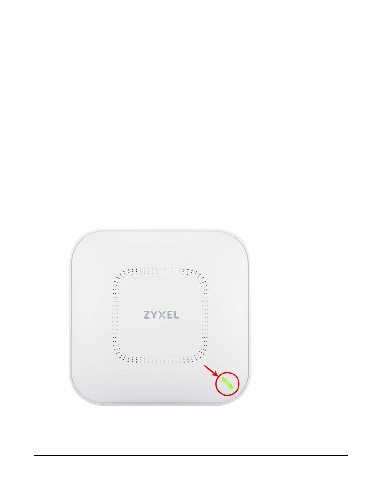
3.1.1 Zyxel Device LED
Figure 14 NWA50AX/NWA90AX LED
NWA50AX/NWA90AX/NWA55AXE Series User’s Guide
28
Page 29
Chapter 3 Hardware
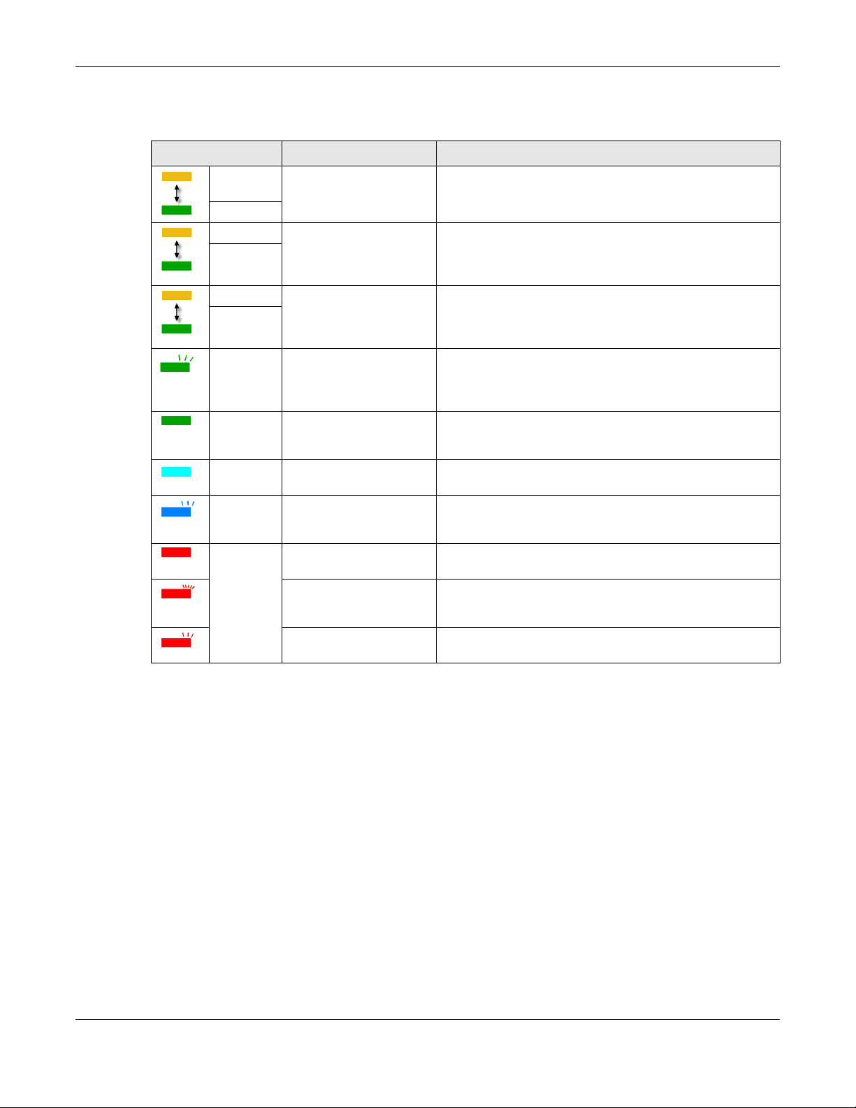
The following are the LED descriptions for the Zyxel Device.
Table 6 Zyxel Device LED
COLOR STATUS DESCRIPTION
Amber Blinks amber for 1 second
Green
Amber Blinks amber and green
Green
Amber Blinks amber and green
Green
Green Slow Blinking (On for 1
Green Steady On The Zyxel Device is ready for use, the Zyxel Device’s wireless
Bright Blue Steady On The Zyxel Device’s wireless interface is activated, but there
Blue Slow Blinking (Blink for 1
Red On The Zyxel Device failed to boot up or is experiencing system
and green for 1 second
alternatively.
alternatively 3 times and
then turns solid green for 3
seconds.
alternatively 2 times and
then turns solid green for 3
seconds.
second, Off for 1 second)
time, Off for 1 second)
Fast Blinking (On for 50
milliseconds, Off for 50
milliseconds)
Slow Blinking (Blink for 3
times, Off for 3 seconds)
The Zyxel Device is booting up or is connecting with NCC.
The Zyxel Device is discovering the NCC or an AC.
The Zyxel Device is managed by an AC but the uplink is
disconnected.
The wireless module of the Zyxel Device is disabled or fails, the
Zyxel Device is using default wireless settings, or the Zyxel
Device is configured to be managed by NCC but is not yet
registered with the NCC.
interface is activated, and/or wireless clients are connected
to the Zyxel Device.
are no wireless clients connected.
The Zyxel Device is performing a Channel Availability Check
(CAC) with Dynamic Frequency Selection (DFS) to monitor a
channel for radar signals.
failure.
The Zyxel Device is undergoing firmware upgrade.
The Uplink port of the Zyxel Device in standalone mode is
disconnected.
NWA50AX/NWA90AX/NWA55AXE Series User’s Guide
29
Page 30
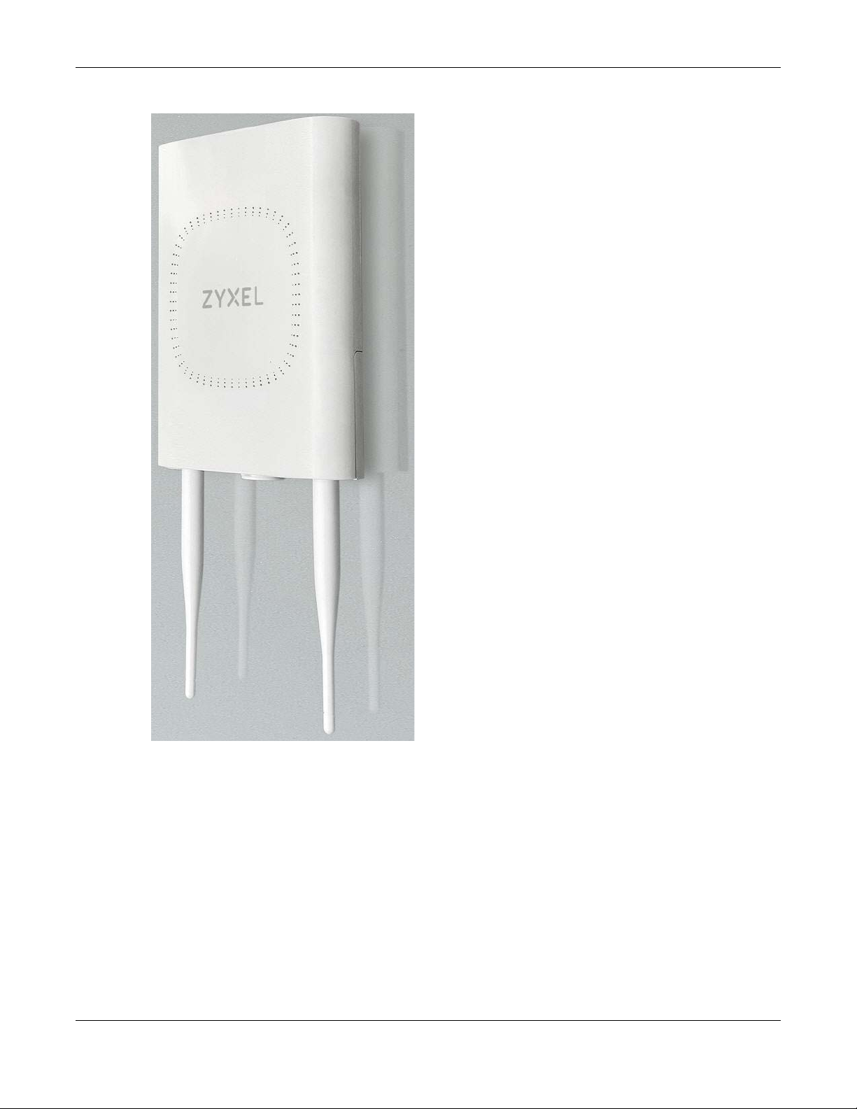
Figure 15 NWA55AXE
Chapter 3 Hardware
Note: The NWA55AXE does not have LED.
NWA50AX/NWA90AX/NWA55AXE Series User’s Guide
30
Page 31

4.1 Overview
The Web Configurator is an HTML-based management interface that allows easy system setup and
management via internet browser. Use a browser that supports HTML5, such Internet Explorer 11, Mozilla
Firefox, or Google Chrome. The recommended screen resolution is 1024 by 768 pixels.
In order to use the Web Configurator you need to allow:
• Web browser pop-up windows from your device.
• JavaScript (enabled by default).
• Java permissions (enabled by default).
CHAPTER 4
Web Configurator
4.2 Accessing the Web Configurator
1 Make sure your Zyxel Device hardware is properly connected. See the Quick Start Guide.
2 If the Zyxel Device and your computer are not connected to a DHCP server, make sure your computer’s
IP address is in the range between "192.168.1.3" and "192.168.1.254".
3 Browse to the Zyxel Device’s DHCP-assigned IP address or http://192.168.1.2. The Login screen appears. If
you are in NCC mode, check the NCC’s Access Point > Monitor > Access Points screen for the Zyxel
Device’s LAN IP address.
NWA50AX/NWA90AX/NWA55AXE Series User’s Guide
31
Page 32

Chapter 4 Web Configurator
Figure 16 Login Page
If a Zyxel Device is in standalone mode and supports NCC, the following page displays.
Here, you can watch a tutorial for using the Zyxel Nebula Control Center (NCC) or access the link to the
NCC, as shown in the following figure. Otherwise, continue with the next step. The NCC is a cloud-based
network management system that allows you to remotely manage and monitor the Zyxel Device (see
Section 2.1.2 on page 20)
Figure 17 Nebula Intro Page
To go to the login page, click Standalone Mode. Login page displays as shown in the following figure.
NWA50AX/NWA90AX/NWA55AXE Series User’s Guide
32
Page 33

Chapter 4 Web Configurator
Figure 18 Login Page in Standalone Mode
4 Enter the user name (default: “admin”) and password (default: “1234”). If the Zyxel Device is being
managed or has been managed by the NCC, check the NCC's Site-Wide > Configure > General
settings screen for the Zyxel Device's current password.
5 Select the language you prefer for the Web Configurator. Click Login.
6 The wizard screen opens when the Zyxel Device is accessed for the first time or when you reset the Zyxel
Device to its default factory settings.
7 If you logged in using the default user name and password, the Update Admin Info screen appears.
Otherwise, the dashboard appears.
Figure 19 Update Admin Info Screen
The Update Admin Info screen appears every time you log in using the default user name and default
password. If you change the password for the default user account, this screen does not appear
anymore.
NWA50AX/NWA90AX/NWA55AXE Series User’s Guide
33
Page 34

Chapter 4 Web Configurator
B
A
C
B
A
C
4.3 Navigating the Web Configurator
The following summarizes how to navigate the Web Configurator from the Dashboard screen. The
following figures show the Dashboard screen for standalone mode and for cloud (NCC) mode. The
screen is different for standalone mode and cloud (NCC) mode and may vary slightly for different
models.
Figure 20 The Web Configurator’s Main Screen for Standalone Mode
Figure 21 The Web Configurator’s Main Screen for Cloud Mode
The Web Configurator’s main screen is divided into these parts:
• A - Title Bar
• B - Navigation Panel
• C - Main Window
NWA50AX/NWA90AX/NWA55AXE Series User’s Guide
34
Page 35

4.3.1 Title Bar
The title bar provides some useful links that always appear over the screens below, regardless of how
deep into the Web Configurator you navigate. If your Zyxel Device is in NCC mode, not all icons will be
available in the Title Bar.
Figure 22 Title Bar
The icons provide the following functions.
Table 7 Title Bar: Web Configurator Icons
LABEL DESCRIPTION
Wizard Click this to open the wizard. See Chapter 7 on page 51 for more information.
Help Click this to open the help page for the current screen.
Forum Click this to go to Zyxel Biz User Forum, where you can get the latest Zyxel Device information
Site Map Click this to see an overview of links to the Web Configurator screens.
CLI Click this to open a popup window that displays the CLI commands sent by the Web
Logout Click this to log out of the Web Configurator.
nebula Click this to open the NCC web site login page in a new tab or window.
Chapter 4 Web Configurator
and have conversations with other people by posting your messages.
Configurator.
Site Map
Click Site MAP to see an overview of links to the Web Configurator screens. Click a screen’s link to go to
that screen.
Figure 23 Site Map
NWA50AX/NWA90AX/NWA55AXE Series User’s Guide
35
Page 36

Chapter 4 Web Configurator
CLI Messages
Click CLI to look at the CLI commands sent by the Web Configurator. These commands appear in a
popup window, such as the following.
Figure 24 CLI Messages
Click Clear to remove the currently displayed information.
Note: See the Command Reference Guide for information about the commands.
4.3.2 Navigation Panel
Use the menu items on the navigation panel to open screens to configure Zyxel Device features. Click
the arrow in the middle of the right edge of the navigation panel to hide the navigation panel menus or
drag it to resize them. The following sections introduce the Zyxel Device’s navigation panel menus and
their screens.
Figure 25 Navigation Panel
4.3.3 Standalone Mode Navigation Panel Menus
The following are the screens available in standalone mode. Note that some screens may not be
available for your Zyxel Device model. See Section 1.4 on page 18 to see which features your Zyxel
Device model supports.
NWA50AX/NWA90AX/NWA55AXE Series User’s Guide
36
Page 37

Chapter 4 Web Configurator
Dashboard
The dashboard displays information such as general device information, system status, system resource
usage, and interface status in widgets that you can re-arrange to suit your needs.
For details on the Dashboard’s features, see Chapter 6 on page 45.
Monitor Menu
The monitor menu screens display status and statistics information.
Table 8 Monitor Menu Screens Summary
FOLDER OR LINK TAB FUNCTION
Network Status Network
Status
Wireless
AP Information Radio List Display information about the radios of the connected APs.
Station Info Station List Display information about the connected stations.
WDS Link Info WDS Link Info Display statistics about the Zyxel Device’s WDS (Wireless Distribution
Detected Device Detected
Device
Log View Log Display log entries for the Zyxel Device.
Display general LAN interface information and packet statistics.
System) connections.
Display information about suspected rogue APs.
Configuration Menu
Use the configuration menu screens to configure the Zyxel Device’s features.
Table 9 Configuration Menu Screens Summary
FOLDER OR LINK TAB FUNCTION
Network IP Setting Configure the IP address for the Zyxel Device Ethernet interface.
VLAN Manage the Ethernet interface VLAN settings.
NCC Discovery Configure proxy server settings to access the NCC.
Wireless
AP
Management
Rogue AP Rogue/Friendly AP
DCS DCS Configure dynamic wireless channel selection.
Object
User User Create and manage users.
AP Profile Radio Create and manage wireless radio settings files that can be
WDS Profile WDS Create and manage WDS profiles that can be used to connect to
WLAN Setting Manage the Zyxel Device’s general wireless settings.
Configure how the Zyxel Device monitors for rogue APs.
List
Setting Manage default settings for all users, general settings for user sessions,
and rules to force user authentication.
associated with different APs.
SSID Create and manage wireless SSID, security, MAC filtering, and layer-2
isolation files that can be associated with different APs.
different APs in WDS.
NWA50AX/NWA90AX/NWA55AXE Series User’s Guide
37
Page 38

Chapter 4 Web Configurator
Table 9 Configuration Menu Screens Summary (continued)
FOLDER OR LINK TAB FUNCTION
Certificate My Certificates Create and manage th e Zyxel Device’s certificates.
Trusted Certificates Import and manage certificates from trusted sources.
System
Host Name Host Name Configure the system and domain name for the Zyxel Device.
Date/Time Date/Time Configure the current date, time, and time zone in the Zyxel Device.
WWW Service Control Configure HTTP, HTTPS, and general authentication.
SSH SSH Configure SSH server and SSH service settings.
FTP FTP Configure FTP server settings.
Log & Report
Log Setting Log Setting Configure the system log, e-mail logs, and remote syslog servers.
Maintenance Menu
Use the maintenance menu screens to manage configuration and firmware files, run diagnostics, and
reboot or shut down the Zyxel Device.
Table 10 Maintenance Menu Screens Summary
FOLDER OR LINK TAB FUNCTION
File Manager Configuration File Manage and upload configuration files for the Zyxel Device.
Firmware Package View the current firmware version and to upload firmware.
Shell Script Manage and run shell script files for the Zyxel Device.
Diagnostics Diagnostics Collect diagnostic information.
LEDs Suppression Enable this feature to keep the LEDs off after the Zyxel Device starts.
Locator Enable this feature to see the actual location of the Zyxel Device
between several devices in the network.
Reboot Reboot Restart the Zyxel Device.
Shutdown Shutdown Turn off the Zyxel Device.
4.3.4 Cloud Mode Navigation Panel Menus
If your Zyxel Device is in NCC mode, you only need to use the Web Configurator for troubleshooting if
your Zyxel Device cannot connect to the Internet.
Dashboard
The dashboard displays general Zyxel Device information, and AP information in widgets that you can
re-arrange to suit your needs.
For details on the Dashboard’s features, see Chapter 22 on page 197.
NWA50AX/NWA90AX/NWA55AXE Series User’s Guide
38
Page 39

Chapter 4 Web Configurator
Configuration Menu
Use the configuration menu screens to configure the Zyxel Device’s features.
Table 11 Configuration Menu Screens Summary
FOLDER OR LINK TAB FUNCTION
Network IP Setting Configure the IP address for the Zyxel Device Ethernet interface.
VLAN Manage the Ethernet interface VLAN settings.
4.3.5 Tables and Lists
The Web Configurator tables and lists are quite flexible and provide several options for how to display
their entries.
4.3.5.1 Manipulating Table Display
Here are some of the ways you can manipulate the Web Configurator tables.
1 Click a column heading to sort the table’s entries according to that column’s criteria.
2 Click the down arrow next to a column heading for more options about how to display the entries. The
options available vary depending on the type of fields in the column. Here are some examples of what
you can do:
• Sort in ascending alphabetical order
• Sort in descending (reverse) alphabetical order
• Select which columns to display
•Group entries by field
•Show entries in groups
• Filter by mathematical operators (<, >, or =) or searching for text.
NWA50AX/NWA90AX/NWA55AXE Series User’s Guide
39
Page 40

Chapter 4 Web Configurator
3 Select a column heading cell’s right border and drag to re-size the column.
4 Select a column heading and drag and drop it to change the column order. A green check mark
displays next to the column’s title when you drag the column to a valid new location.
5 Use the icons and fields at the bottom of the table to navigate to different pages of entries and control
how many entries display at a time.
NWA50AX/NWA90AX/NWA55AXE Series User’s Guide
40
Page 41

4.3.5.2 Working with Table Entries
The tables have icons for working with table entries. A sample is shown next. You can often use the [Shift]
or [Ctrl] key to select multiple entries to remove, activate, or deactivate.
Figure 26 Common Table Icons
Here are descriptions for the most common table icons.
Table 12 Common Table Icons
LABEL DESCRIPTION
Add Click this to create a new entry. For features where the entry’s position in the numbered list is
important (features where the Zyxel Device applies the table’s entries in order like the
firewall for example), you can select an entry and click Add to create a new entry after the
selected entry.
Edit Double-click an entry or select it and click Edit to open a screen where you can modify the
entry’s settings. In some tables you can just click a table entry and edit it directly in the
table. For those types of tables small red triangles display for table entries with changes that
you have not yet applied.
Remove To remove an entry, select it and click Remove. The Zyxel Device confirms you want to
remove it before doing so.
Activate To turn on an entry, select it and click Activate.
Inactivate To turn off an entry, select it and click Inactivate.
Object Reference Select an entry and click Object Reference to open a screen that shows which settings use
the entry.
Chapter 4 Web Configurator
NWA50AX/NWA90AX/NWA55AXE Series User’s Guide
41
Page 42

PART I
Standalone
Configuration
42
Page 43

Standalone Configuration
5.1 Overview
The Zyxel Device is in standalone mode by default. Use the web configurator to manage and configure
the Zyxel Device directly. As shown in the following figure, WiFi clients can connect to the Zyxel Device
(A) to access network resources.
CHAPTER 5
5.2 Starting and Stopping the Zyxel Device
Here are some of the ways to start and stop the Zyxel Device.
Always use Maintenance > Shutdown or the shutdown command
before you turn off the Zyxel Device or remove the power. Not doing so
can cause the firmware to become corrupt.
Table 13 Starting and Stopping the Zyxel Device
METHOD DESCRIPTION
Turning on the power A cold start occurs when you turn on the power to the Zyxel Device. The Zyxel Device
Rebooting the Zyxel
Device
powers up, checks the hardware, and starts the system processes.
A warm start (without powering down and powering up again) occurs when you use the
Reboot button in the Reboot screen or when you use the reboot command. The Zyxel
Device writes all cached data to the local storage, stops the system processes, and then
does a warm start.
NWA50AX/NWA90AX/NWA55AXE Series User’s Guide
43
Page 44

Chapter 5 Standalone Configuration
Table 13 Starting and Stopping the Zyxel Device (continued)
METHOD DESCRIPTION
Using the RESET button If you press the RESET button on the back of the Zyxel Device, the Zyxel Device sets the
configuration to its default values and then reboots. See Section 25.6 on page 215 for
more information.
Note: Some models do not have a RESET button due to feature differences.
Clicking Maintenance
> Shutdown >
Shutdown or using the
shutdown command
Disconnecting the
power
Clicking Maintenance > Shutdown > Shutdown or using the shutdown command writes all
cached data to the local storage and stops the system processes. Wait for the Zyxel
Device to shut down and then manually turn off or remove the power. It does not turn off
the power.
Power off occurs when you turn off the power to the Zyxel Device. The Zyxel Device simply
turns off. It does not stop the system processes or write cached data to local storage.
The Zyxel Device does not stop or start the system processes when you apply configuration files or run
shell scripts although you may temporarily lose access to network resources.
NWA50AX/NWA90AX/NWA55AXE Series User’s Guide
44
Page 45

6.1 Overview
A
B
D
C
This screen displays general device information, system status, system resource usage, and interface
status in widgets that you can re-arrange to suit your needs. You can also collapse, refresh, and close
individual widgets. Fields in this screen may slightly differ by models.
Figure 27 Dashboard
CHAPTER 6
Dashboard
The following table describes the labels in this screen.
Table 14 Dashboard
LABEL DESCRIPTION
Widget Settings (A) Use this link to re-open closed widgets. Widgets that are already open appear grayed out.
Refresh Time Setting
(B)
Refresh Now (C) Click this to update the widget’s information immediately.
Close Widget (D) Click this to close the widget. Use Widget Settings to re-open it.
Device Information
System Name This field displays the name used to identify the Zyxel Device on any network. Click the icon
System Location This field displays the location of the Zyxel Device. Click the icon to open the screen where
Model Name This field displays the model name of this Zyxel Device.
Serial Number This field displays the serial number of this Zyxel Device.
Set the interval for refreshing the information displayed in the widget.
to open the screen where you can change it.
you can change it.
NWA50AX/NWA90AX/NWA55AXE Series User’s Guide
45
Page 46

Chapter 6 Dashboard
Table 14 Dashboard (continued)
LABEL DESCRIPTION
MAC Address
Range
Firmware Version This field displays the version number and date of the firmware the Zyxel Device is currently
Last Firmware
Upgrade Status
Last Firmware
Upgrade
System Resources
CPU Usage This field displays what percentage of the Zyxel Device’s processing capability is currently
Memory Usage This field displays what percentage of the Zyxel Device’s RAM is currently being used. Hover
Flash Usage This field displays what percentage of the Zyxel Device’s onboard flash memory is currently
Ethernet Neighbor
Local Port
(Description)
Model Name This field displays the model name of the discovered device.
System Name This field displays the system name of the discovered device.
FW Version This field displays the firmware version of the discovered device.
Port (Description) This field displays the discovered device’s port which is connected to the Zyxel Device.
IP This field displays the IP address of the discovered device. Click the IP address to access
MAC This field displays the MAC address of the discovered device.
WDS (Wireless Distribution System) Uplink/Downlink Status
MAC Address This field displays the MAC address of the root AP or repeater to which the Zyxel Device is
Radio This field displays the radio number on the root AP or repeater to which the Zyxel Device is
Channel This field displays the channel number on the root AP or repeater to which the Zyxel Device
SSID This field displays the name of the wireless network to which the Zyxel Device is connected
Security Mode This field displays which secure encryption methods is being used by the Zyxel Device to
Link Status This field displays the RSSI (Received Signal Strength Indicator) and transmission/reception
System Status
System Uptime This field displays how long the Zyxel Device has been running since it last restarted or was
Current Date/
Time
Current Login
User
This field displays the MAC addresses used by the Zyxel Device. Each physical port or
wireless radio has one MAC address. The first MAC address is assigned to the Ethernet LAN
port, the second MAC address is assigned to the first radio, and so on.
running. Click the icon to open the screen where you can upload firmware.
This field displays whether the latest firmware update was successfully completed.
This field displays the date and time when the last firmware update was made.
being used. Hover your cursor over this field to display the Show CPU Usage icon that takes
you to a chart of the Zyxel Device’s recent CPU usage.
your cursor over this field to display the Show Memory Usage icon that takes you to a chart
of the Zyxel Device’s recent memory usage.
being used.
This field displays the port of the Zyxel Device, on which the neighboring device is
discovered.
and manage the discovered device using its Web Configurator.
connected using WDS.
connected using WDS.
is connected using WDS.
using WDS.
connect to the root AP or repeater using WDS.
rate of the wireless connection in WDS.
turned on.
This field displays the current date and time in the Zyxel Device. The format is yyyy-mm-dd
hh:mm:ss.
This field displays the user name used to log in to the current session, the amount of
reauthentication time remaining, and the amount of lease time remaining.
NWA50AX/NWA90AX/NWA55AXE Series User’s Guide
46
Page 47

Chapter 6 Dashboard
Table 14 Dashboard (continued)
LABEL DESCRIPTION
Boot Status This field displays details about the Zyxel Device’s startup state.
OK - The Zyxel Device started up successfully.
Firmware update OK - A firmware update was successful.
Problematic configuration after firmware update - The application of the configuration
failed after a firmware upgrade.
System default configuration - The Zyxel Device successfully applied the system default
configuration. This occurs when the Zyxel Device starts for the first time or you intentionally
reset the Zyxel Device to the system default settings.
Fallback to lastgood configuration - The Zyxel Device was unable to apply the startupconfig.conf configuration file and fell back to the lastgood.conf configuration file.
Fallback to system default configuration - The Zyxel Device was unable to apply the
lastgood.conf configuration file and fell back to the system default configuration file
(system-default.conf).
Booting in progress - The Zyxel Device is still applying the system configuration.
Management
Mode
Cloud Control Status This field displays:
This shows whether the Zyxel Device is set to work as a stand alone AP.
Nebula
Discovery
• The Zyxel Device Internet connection status.
• The connection status between the Zyxel Device and NCC.
• The Zyxel Device registration status on NCC.
Mouse over the circles to display detailed information.
To pass your Zyxel Device management to NCC, first make sure your Zyxel Device is
connected to the Internet. Then go to NCC and register your Zyxel Device. You can also
view this information in Configuration > Network > NCC Discovery.
1. Internet
Green - The Zyxel Device is connected to the Internet.
Orange - The Zyxel Device is not connected to the Internet.
2. Nebula
Green - The Zyxel Device is connected to NCC.
Orange - The Zyxel Device is not connected to NCC.
3. Registration
Green - The Zyxel Device is registered on NCC.
Gray - The Zyxel Device is not registered on NCC.
Note: All circles will gray out if you disable Nebula Discovery.
Slide the switch to the right to enable NCC discovery on the Zyxel Device. The Zyxel Device
will connect to NCC and change to the NCC management mode if it:
• is connected to the Internet.
• has been registered on NCC.
Interface Status
Summary
Name This field displays the name of each interface.
If an Ethernet interface does not have any physical ports associated with it, its entry is
displayed in light gray text. Click the Detail icon to go to a (more detailed) summary screen
of interface statistics.
NWA50AX/NWA90AX/NWA55AXE Series User’s Guide
47
Page 48

Chapter 6 Dashboard
Table 14 Dashboard (continued)
LABEL DESCRIPTION
Status This field displays the current status of each interface. The possible values depend on what
type of interface it is.
Inactive - The Ethernet interface is disabled.
Down - The Ethernet interface is enabled but not connected.
Speed / Duplex - The Ethernet interface is enabled and connected. This field displays the
port speed and duplex setting (Full or Half).
VID This field displays the VLAN ID to which the interface belongs.
IP Addr/Netmask This field displays the current IP address and subnet mask assigned to the interface. If the IP
IP Assignment This field displays how the interface gets its IP address.
Action If the interface has a static IP address, this shows n/a.
WLAN Interface
Status Summary
Status This displays whether or not the WLAN interface is activated.
MAC Address This displays the MAC address of the radio.
Radio This indicates the radio number on the Zyxel Device.
Band This indicates the wireless frequency band currently being used by the radio.
OP Mode This indicates the radio’s operating mode. Operating modes are AP (MBSSID), Root AP or
Channel This indicates the channel number the radio is using.
Station This displays the number of wireless clients connected to the Zyxel Device.
AP Information This shows a summary of connected wireless Access Points (APs).
All Sensed Device This sections displays a summary of all wireless devices detected by the network. Click the
Un-Classified AP This displays the number of detected unclassified APs.
Rogue AP This displays the number of detected rogue APs.
Friendly AP This displays the number of detected friendly APs.
address is 0.0.0.0, the interface is disabled or did not receive an IP address and subnet mask
via DHCP.
Static - This interface has a static IP address.
DHCP Client - This interface gets its IP address from a DHCP server.
If the interface has a dynamic IP address, use this field to get or to update the IP address for
the interface. Click Renew to send a new DHCP request to a DHCP server.
This displays status information for the WLAN interface.
Repeater.
link to go to the Monitor > Wireless > Detected Device screen.
6.1.1 CPU Usage
Use this screen to look at a chart of the Zyxel Device’s recent CPU usage. To access this screen, click
CPU Usage in the dashboard.
NWA50AX/NWA90AX/NWA55AXE Series User’s Guide
48
Page 49

Chapter 6 Dashboard
Figure 28 Dashboard > CPU Usage
The following table describes the labels in this screen.
Table 15 Dashboard > CPU Usage
LABEL DESCRIPTION
% The y-axis represents the percentage of CPU usage.
time The x-axis shows the time period over which the CPU usage occurred.
Refresh Interval Enter how often you want this window to be automatically updated.
Refresh Now Click this to update the information in the window right away.
6.1.2 Memory Usage
Use this screen to look at a chart of the Zyxel Device’s recent memory (RAM) usage. To access this
screen, click Memory Usage in the dashboard.
Figure 29 Dashboard > Memory Usage
NWA50AX/NWA90AX/NWA55AXE Series User’s Guide
49
Page 50

Chapter 6 Dashboard
The following table describes the labels in this screen.
Table 16 Dashboard > Memory Usage
LABEL DESCRIPTION
% The y-axis represents the percentage of RAM usage.
time The x-axis shows the time period over which the RAM usage occurred
Refresh Interval Enter how often you want this window to be automatically updated.
Refresh Now Click this to update the information in the window right away.
NWA50AX/NWA90AX/NWA55AXE Series User’s Guide
50
Page 51

7.1 Accessing the Wizard
When you log into the Web Configurator for the first time or when you reset the Zyxel Device to its
default configuration, the wizard screen displays.
Note: If you have already configured the wizard screens and want to open it again, click the
Wizard icon on the upper right corner of any Web Configurator screen.
7.2 Using the Wizard
This wizard helps you configure the Zyxel Device IP address, change time zone, daylight saving and
radio settings, and edit an SSID profile to change general wireless and wireless security settings.
CHAPTER 7
Setup Wizard
7.2.1 Step 1 Time Settings
Use this screen to configure the Zyxel Device’s country code, time zone and daylight saving time.
• Country Code: Select the country where the Zyxel Device is located.
Note: The country code field is not available and you cannot change the country code if the
Zyxel Device products comply with the U.S. laws, policies and regulations and are to be
sold to the U.S. market.
• Time Zone: Select the time zone of your location. This will set the time difference between your time
zone and Greenwich Mean Time (GMT).
• Enable Daylight Saving: Select the option if you use Daylight Saving Time. Configure the day and time
when Daylight Saving Time starts and ends.
• Offset allows you to specify how much the clock changes when daylight saving begins and ends.
Enter a number from 1 to 5.5 (by 0.5 increments).
Click Next to proceed. Click Cancel to close the wizard without saving.
NWA50AX/NWA90AX/NWA55AXE Series User’s Guide
51
Page 52

Chapter 7 Setup Wizard
Figure 30 Wizard: Time Settings
7.2.2 Step 2 Password and Uplink Connection
Use this screen to configure the Zyxel Device’s system password and IP address.
Change Password: Enter a new password and retype it to confirm.
Uplink Connection: Select Auto (DHCP) if the Zyxel Device is connected to a router with the DHCP server
enabled. You then need to check the router for the IP address assigned to the Zyxel Device in order to
access the Zyxel Device’s Web Configurator again.
Otherwise, select Static IP when the Zyxel Device is NOT connected to a router or you want to assign it a
fixed IP address. You will need to manually enter:
• the Zyxel Device’s IP address and subnet mask.
• the IP address of the router that helps forward traffic.
• a DNS server's IP address. The Domain Name System (DNS) maps a domain name to an IP address
and vice versa. The DNS server is extremely important because without it, you must know the IP
address of a computer before you can access it.
Click Prev to return to the previous screen. Click Next to proceed. Click Cancel to close the wizard
without saving.
Note: The number of characters shown is not an actual representation of your current
password. If you click Next without changing password in the New Password and
Confirm Password fields, your current password will not be changed.
NWA50AX/NWA90AX/NWA55AXE Series User’s Guide
52
Page 53

Figure 31 Wizard: Change Password and Uplink Connection
7.2.3 Step 3 Radio
Use this screen to configure the Zyxel Device’s radio transmitter(s).
Chapter 7 Setup Wizard
• Channel Selection: Select Auto to have the Zyxel Device automatically choose a radio channel that
has least interference. Otherwise, select Manual and specify a channel the Zyxel Device will use in the
2.4 GHz or 5 GHz wireless LAN. The options vary depending on the frequency band and the country
you are in.
• Maximum Output Power: Enter the maximum output power of the Zyxel Device. If there is a high
density of APs in an area, decrease the output power of the Zyxel Device to reduce interference with
other APs.
Note: Reducing the output power also reduces the Zyxel Device’s effective broadcast radius.
Click Prev to return to the previous screen. Click Next to proceed. Click Cancel to close the wizard
without saving.
Figure 32 Wizard: Radio
NWA50AX/NWA90AX/NWA55AXE Series User’s Guide
53
Page 54

7.2.4 Step 4 SSID
Use this screen to enable, disable or edit an SSID profile.
Select an SSID profile and click the Status switch to turn it on or off. To change an SSID profile’s settings,
such as the SSID (WiFi network name) and WiFi password, double-click the SSID profile entry from the list.
See Section 7.2.4.1 on page 54 for more information.
Note: You cannot add or remove an SSID profile after running the setup wizard.
Figure 33 Wizard: SSID
Chapter 7 Setup Wizard
7.2.4.1 Edit SSID Profile
Use this screen to configure an SSID profile.
The screen varies depending on the security type you selected.
• SSID: Enter a descriptive name of up to 32 printable characters for the wireless LAN.
• VLAN ID: Enter a VLAN ID for the Zyxel Device to use to tag traffic originating from this SSID.
Band Mode: Select the wireless band which this profile should use. 2.4 GHz is the frequency used by
IEEE 802.11b/g/n wireless clients. 5 GHz is the frequency used by IEEE 802.11ac/a/n wireless clients.
• Security Type: Select WPA2 to add security on this wireless network. Otherwise, select OPEN to allow
any wireless client to associate this network without authentication.
• Personal: If you set Security Type to WPA2 and select Personal, enter a pre-shared key of between 8
and 63 case-sensitive ASCII characters (including spaces and symbols) or 64 hexadecimal
characters.
Note: For Zyxel Device models that support enterprise security mode:
You can select the Enterprise mode in Configuration > Object > AP Profile > SSID >
Security List > Edit.
Click OK to proceed. Click Cancel to close the screen without saving.
NWA50AX/NWA90AX/NWA55AXE Series User’s Guide
54
Page 55

Chapter 7 Setup Wizard
Figure 34 Wizard: SSID: Edit (WPA2-Personal)
7.2.5 Summary
Use this screen to check whether what you have configured is correct. Click Save to apply your settings
and complete the wizard setup. Otherwise, click Prev to return to the previous screen or click Cancel to
close the wizard without saving.
Figure 35 Wizard: Summary
NWA50AX/NWA90AX/NWA55AXE Series User’s Guide
55
Page 56

8.1 Overview
Use the Monitor screens to check status and statistics information.
8.1.1 What You Can Do in this Chapter
• The Network Status screen (Section 8.3 on page 57) displays general LAN interface information and
packet statistics.
• The AP Information > Radio List screen (Section 8.4 on page 59) displays statistics about the wireless
radio transmitters in the Zyxel Device.
• The Station Info screen (Section 8.5 on page 62) displays statistics pertaining to the associated
stations.
• The WDS Link Info screen (Section 8.6 on page 63) displays statistics about the Zyxel Device’s WDS
(Wireless Distribution System) connections.
• The Detected Device screen (Section 8.7 on page 64) displays information about suspected rogue
APs.
• The View Log screen (Section 8.8 on page 66) displays the Zyxel Device’s current log messages. You
can change the way the log is displayed, you can e-mail the log, and you can also clear the log in
this screen.
CHAPTER 8
Monitor
8.2 What You Need to Know
The following terms and concepts may help as you read through the chapter.
Rogue AP
Rogue APs are wireless access points operating in a network’s coverage area that are not under the
control of the network’s administrators, and can open up holes in a network’s security. See Chapter 14
on page 169 for details.
Friendly AP
Friendly APs are other wireless access points that are detected in your network, as well as any others that
you know are not a threat (those from neighboring networks, for example). See Chapter 14 on page 169
for details.
NWA50AX/NWA90AX/NWA55AXE Series User’s Guide
56
Page 57

8.3 Network Status
Use this screen to look at general Ethernet interface information and packet statistics. To access this
screen, click Monitor > Network Status.
Figure 36 Monitor > Network Status
Chapter 8 Monitor
The following table describes the labels in this screen.
Table 17 Monitor > Network Status
LABEL DESCRIPTION
Interface
Summary
IPv6 Interface
Summary
Name This field displays the name of the physical Ethernet port on the Zyxel Device.
Status This field displays the current status of each physical port on the Zyxel Device.
VID This field displays the VLAN ID to which the port belongs.
IP Addr/Netmask
IP Address
IP Assignment This field displays how the interface gets its IPv4 address.
Action Use this field to get or to update the IP address for the interface. Click Renew to send a new
Port Statistics Table
Poll Interval Enter how often you want this window to be updated automatically, and click Set Interval.
Use the Interface Summary section for IPv4 network settings. Use the IPv6 Interface Summary
section for IPv6 network settings if you connect your Zyxel Device to an IPv6 network. Both
sections have similar fields as described below.
Down - The port is not connected.
Speed / Duplex - The port is connected. This field displays the port speed and duplex setting
(Full or Half).
This field displays the current IP address (and subnet mask) of the interface. If the IP address is
0.0.0.0 (in the IPv4 network) or :: (in the IPv6 network), the interface does not have an IP address
yet.
Static - This interface has a static IPv4 address.
DHCP Client - This interface gets its IPv4 address from a DHCP server.
DHCP request to a DHCP server. If the interface cannot use one of these ways to get or to
update its IP address, this field displays n/a.
NWA50AX/NWA90AX/NWA55AXE Series User’s Guide
57
Page 58

Chapter 8 Monitor
Table 17 Monitor > Network Status (continued)
LABEL DESCRIPTION
Set Interval Click this to set the Poll Interval the screen uses.
Stop Click this to stop the window from updating automatically. You can start it again by setting the
Poll Interval and clicking Set Interval.
Switch to Graphic
View
Name This field displays the name of the interface.
Status This field displays the current status of the physical port.
TxPkts This field displays the number of packets transmitted from the Zyxel Device on the physical port
RxPkts This field displays the number of packets received by the Zyxel Device on the physical port
Tx Bcast This field displays the number of broadcast packets transmitted from the Zyxel Device on the
Rx Bcast This field displays the number of broadcast packets received by the Zyxel Device on the
Collisions This field displays the number of collisions on the physical port since it was last connected.
Tx This field displays the transmission speed, in bytes per second, on the physical port in the one-
Rx This field displays the reception speed, in bytes per second, on the physical port in the one-
Up Time This field displays how long the physical port has been connected.
System Up Time This field displays how long the Zyxel Device has been running since it last restarted or was
Click this to display the port statistics as a line graph.
Down - The physical port is not connected.
Speed / Duplex - The physical port is connected. This field displays the port speed and duplex
setting (Full or Half).
since it was last connected.
since it was last connected.
physical port since it was last connected.
physical port since it was last connected.
second interval before the screen updated.
second interval before the screen updated.
turned on.
8.3.1 Port Statistics Graph
Use the port statistics graph to look at a line graph of packet statistics for the Ethernet port. To view, click
Monitor > Network Status and then the Switch to Graphic View button.
NWA50AX/NWA90AX/NWA55AXE Series User’s Guide
58
Page 59

Chapter 8 Monitor
Figure 37 Monitor > Network Status > Switch to Graphic View
The following table describes the labels in this screen.
Table 18 Monitor > Network Status > Switch to Graphic View
LABEL DESCRIPTION
Refresh Interval Enter how often you want this window to be automatically updated.
Refresh Now Click this to update the information in the window right away.
Port Selection Select the Ethernet port for which you want to view the packet statistics.
Switch to Grid
View
Kbps/Mbps The y-axis represents the speed of transmission or reception.
Time The x-axis shows the time period over which the transmission or reception occurred.
TX This line represents traffic transmitted from the Zyxel Device on the physical port since it was last
RX This line represents the traffic received by the Zyxel Device on the physical port since it was last
Last Update This field displays the date and time the information in the window was last updated.
8.4 Radio List
Use this screen to view statistics for the Zyxel Device’s wireless radio transmitters. To access this screen,
click Monitor > Wireless > AP Information > Radio List.
Click this to display the port statistics as a table.
connected.
connected.
NWA50AX/NWA90AX/NWA55AXE Series User’s Guide
59
Page 60

Chapter 8 Monitor
Figure 38 Monitor > Wireless > AP Information > Radio List (for Zyxel Device that supports WDS)
Figure 39 Monitor > Wireless > AP Information > Radio List (for Zyxel Device that does not support WDS)
The following table describes the labels in this screen.
Table 19 Monitor > Wireless > AP Information > Radio List
LABEL DESCRIPTION
More Information Click this to view additional information about the selected radio’s wireless traffic and station
Status This displays whether or not the radio is enabled.
MAC Address This displays the MAC address of the radio.
Radio This indicates the radio number on the Zyxel Device to which it belongs.
OP Mode This indicates the radio’s operating mode. Operating modes are AP (MBSSID), Root AP or
AP/WDS Profile This indicates the AP profile name and WDS profile name to which the radio belongs.
Profile This indicates the AP profile name to which the radio belongs.
Frequency Band This indicates the wireless frequency band currently being used by the radio.
Channel This indicates the radio’s channel ID.
Transmit Power This displays the output power of the radio.
Station This displays the number of wireless clients connected to this radio on the Zyxel Device.
Upload This displays the total number of packets received by the radio.
Download This displays the total number of packets transmitted by the radio.
Channel
Utilization
count. Information spans a 24 hour period.
Repeater.
This field is available only on the Zyxel Device that supports WDS.
This field is available only on the Zyxel Device that does not support WDS.
This indicates how much IEEE 802.11 traffic the radio can receive on the channel. It displays
what percentage of the radio’s channel is currently being used.
NWA50AX/NWA90AX/NWA55AXE Series User’s Guide
60
Page 61

Chapter 8 Monitor
8.4.1 AP Mode Radio Information
This screen allows you to view a selected radio’s SSID details, wireless traffic statistics and station count
for the preceding 24 hours. To access this window, select a radio and click the More Information button
in the Radio List screen.
Figure 40 Monitor > Wireless > AP Information > Radio List > More Information
NWA50AX/NWA90AX/NWA55AXE Series User’s Guide
61
Page 62

Chapter 8 Monitor
The following table describes the labels in this screen.
Table 20 Monitor > Wireless > AP Information > Radio List > More Information
LABEL DESCRIPTION
SSID Detail This list shows information about all the wireless clients that have connected to the specified
# This is the items sequential number in the list. It has no bearing on the actual data in this list.
SSID Name This displays an SSID associated with this radio. There can be up to eight maximum.
BSSID This displays a BSSID associated with this radio. The BSSID is tied to the SSID.
Security
Mode
VLAN This displays the VLAN ID associated with the SSID.
Traffic Statistics This graph displays the overall traffic information of the radio over the preceding 24 hours.
Kbps/Mbps This y-axis represents the amount of data moved across this radio in megabytes per second.
Time This x-axis represents the amount of time over which the data moved across this radio.
Station Count This graph displays the connected station information of the radio over the preceding 24 hours
Stations The y-axis represents the number of connected stations.
Time The x-axis shows the time period over which a station was connected.
Last Update This field displays the date and time the information in the window was last updated.
OK Click this to close this window.
Cancel Click this to close this window.
radio over the preceding 24 hours.
This displays the security mode in which the SSID is operating.
8.5 Station List
Use this screen to view statistics pertaining to the associated stations (or “wireless clients”). Click Monitor
> Wireless > Station Info to access this screen.
Figure 41 Monitor > Wireless > Station Info
The following table describes the labels in this screen.
Table 21 Monitor > Wireless > Station Info
LABEL DESCRIPTION
# This is the station’s index number in this list.
IP Address This is the station’s IP address.
MAC Address This is the station’s MAC address.
NWA50AX/NWA90AX/NWA55AXE Series User’s Guide
62
Page 63

Chapter 8 Monitor
Table 21 Monitor > Wireless > Station Info (continued)
LABEL DESCRIPTION
Radio This is the radio number on the Zyxel Device to which the station is connected.
Capability This displays the supported standard currently being used by the station or the standards
supported by the station.
802.11 Features This displays whether the station supports IEEE802.11r, IEEE 802.11k, IEEE 802.11v or none of the
above (N/A).
SSID Name This indicates the name of the wireless network to which the station is connected. A single AP
Security Mode This indicates which secure encryption methods is being used by the station to connect to the
Signal Strength This is the RSSI (Received Signal Strength Indicator) of the station’s wireless connection.
Tx Rate This is the maximum transmission rate of the station.
Rx Rate This is the maximum reception rate of the station.
Association Time This displays the time the station first associated with the Zyxel Device’s wireless network.
Refresh Click this to refresh the items displayed on this page.
can have multiple SSIDs or networks.
network.
8.6 WDS Link Info
Use this screen to view the WDS traffic statistics between the Zyxel Device and a root AP or repeaters.
See Section 1.2 on page 12 to know more about WDS. Click Monitor > Wireless > WDS Link Info to access
this screen.
Figure 42 Monitor > Wireless > WDS Link Info
NWA50AX/NWA90AX/NWA55AXE Series User’s Guide
63
Page 64

Chapter 8 Monitor
The following table describes the labels in this screen.
Table 22 Monitor > Wireless > WDS Link Info
LABEL DESCRIPTION
WDS Uplink Info
WDS Downlink
Info
# This is the index number of the root AP or repeater in this list.
MAC Address This is the MAC address of the root AP or repeater to which the Zyxel Device is connected using
Radio This is the radio number on the root AP or repeater to which the Zyxel Device is connected
SSID Name This indicates the name of the wireless network to which the Zyxel Device is connected using
Security Mode This indicates which secure encryption methods is being used by the Zyxel Device to connect
Signal Strength This is the RSSI (Received Signal Strength Indicator) of the wireless connection in WDS.
Tx Rate This is the maximum transmission rate of the root AP or repeater to which the Zyxel Device is
Rx Rate This is the maximum reception rate of the root AP or repeater to which the Zyxel Device is
Association Time This displays the time the Zyxel Device first associated with the wireless network using WDS.
Refresh Click this to refresh the items displayed on this page.
Uplink refers to the WDS link from the repeaters to the root AP.
Downlink refers to the WDS link from the root AP to the repeaters.
When the Zyxel Device is in root AP mode and connected to a repeater, only the downlink
information is displayed.
When the Zyxel Device is in repeater mode and connected to a root AP directly or via another
repeater, the uplink information is displayed.
When the Zyxel Device is in repeater mode and connected to a root AP and other repeater(s),
both the uplink and downlink information would be displayed.
WDS.
using WDS.
WDS.
to the root AP or repeater using WDS.
connected using WDS.
connected using WDS.
8.7 Detected Device
Use this screen to view information about surrounding APs which you could mark as Rogue or Friendly.
Click Monitor > Wireless > Detected Device to access this screen. For more information about Rogue
APs, see Section 10.3 on page 82.
Note: Turn on rogue AP detection in the Configuration > Wireless > Rogue AP screen to detect
other APs.
NWA50AX/NWA90AX/NWA55AXE Series User’s Guide
64
Page 65

Chapter 8 Monitor
Figure 43 Monitor > Wireless > Detected Device (for Zyxel Device that does not support Monitor mode)
The following table describes the labels in this screen.
Table 23 Monitor > Wireless > Detected Device
LABEL DESCRIPTION
Discovered APs
Rogue AP This shows how many devices are detected as rogue APs.
Suspected rogue APThis shows how many devices are detected as possible rogue APs based on the classification
Friendly AP This shows how many devices are detected as friendly APs.
Un-classified AP This shows how many devices are detected, but have not been classified as either Rogue or
Detect Now Click this button for the Zyxel Device to scan for APs in the network.
Detected Device
rule(s) in Section 10.3 on page 82.
Friendly by the Zyxel Device.
NWA50AX/NWA90AX/NWA55AXE Series User’s Guide
65
Page 66

Chapter 8 Monitor
Table 23 Monitor > Wireless > Detected Device (continued)
LABEL DESCRIPTION
Mark as Rogue APClick this button to mark the selected AP as a rogue AP. For more on managing rogue APs, see
the Configuration > Wireless > Rogue AP screen (Section 10.3 on page 82).
Mark as Friendly APClick this button to mark the selected AP as a friendly AP. For more on managing friendly APs,
see the Configuration > Wireless > Rogue AP screen (Section 10.3 on page 82).
# This is the detected device’s index number in this list.
Status This indicates the detected device’s status.
Device This indicates the type of device detected.
Role This indicates the detected device’s role (such as friendly or rogue).
Classified by This indicates the detected device’s classification rule.
MAC Address This indicates the detected device’s MAC address.
SSID Name This indicates the detected device’s SSID.
Channel ID This indicates the detected device’s channel ID.
802.11 Mode This indicates the 802.11 mode (a/b/g/n/ac/ax) transmitted by the detected device.
Security This indicates the encryption method (if any) used by the detected device.
Description This displays the detected device’s description. For more on managing friendly and rogue APs,
Last Seen This indicates the last time the device was detected by the Zyxel Device.
Refresh Click this to refresh the items displayed on this page.
see the Configuration > Wireless > Rogue AP screen (Section 10.3 on page 82).
8.8 View Log
Log messages are stored in two separate logs, one for regular log messages and one for debugging
messages. In the regular log, you can look at all the log messages by selecting All Logs, or you can
select a specific category of log messages (for example, user). You can also look at the debugging log
by selecting Debug Log. All debugging messages have the same priority.
To access this screen, click Monitor > Log. The log is displayed in the following screen.
Note: When a log reaches the maximum number of log messages, new log messages
automatically overwrite existing log messages, starting with the oldest existing log
message first.
Events that generate an alert (as well as a log message) display in red. Regular logs display in black.
Click a column’s heading cell to sort the table entries by that column’s criteria. Click the heading cell
again to reverse the sort order.
The Web Configurator saves the filter settings once you click Search. If you leave the View Log screen
and return to it later, the last filter settings would still apply.
NWA50AX/NWA90AX/NWA55AXE Series User’s Guide
66
Page 67

Figure 44 Monitor > Log > View Log
Chapter 8 Monitor
The following table describes the labels in this screen.
Table 24 Monitor > Log > View Log
LABEL DESCRIPTION
Show Filter / Hide
Filter
Display Select the category of log message(s) you want to view. You can also view All Logs at one
Priority This displays when you show the filter. Select the priority of log messages to display. The log
Source Address This displays when you show the filter. Type the source IP address of the incoming packet that
Click this button to show or hide the filter settings.
If the filter settings are hidden, the Display, Email Log Now, Refresh, and Clear Log fields are
available.
If the filter settings are shown, the Display, Priority, Source Address, Destination Address, Source
Interface, Destination Interface, Protocol, Keyword, and Search fields are available.
time, or you can view the Debug Log.
displays the log messages with this priority or higher. Choices are: any, emerg, alert, crit, error,
warn, notice, and info, from highest priority to lowest priority. This field is read-only if the
Category is Debug Log.
generated the log message. Do not include the port in this filter.
NWA50AX/NWA90AX/NWA55AXE Series User’s Guide
67
Page 68

Chapter 8 Monitor
Table 24 Monitor > Log > View Log (continued)
LABEL DESCRIPTION
Destination
Address
Source Interface This displays when you show the filter. Select the source interface of the packet that generated
Destination
Interface
Protocol This displays when you show the filter. Select a service protocol whose log messages you would
Keyword This displays when you show the filter. Type a keyword to look for in the Message, Source,
Search This displays when you show the filter. Click this button to update the log using the current filter
Email Log Now Click this button to send log messages to the Active e-mail addresses specified in the Send Log
Refresh Click this to update the list of logs.
Clear Log Click this button to clear the whole log, regardless of what is currently displayed on the screen.
# This field is a sequential value, and it is not associated with a specific log message.
Time This field displays the time the log message was recorded.
Priority This field displays the priority of the log message. It has the same range of values as the Priority
Category This field displays the log that generated the log message. It is the same value used in the
Message This field displays the reason the log message was generated. The text “[count=x]”, where x is a
Source This field displays the source IP address and the port number in the event that generated the
Source Interface This field displays the source interface of the packet that generated the log message.
Destination This field displays the destination IP address and the port number of the event that generated
Destination
Interface
Protocol This field displays the service protocol in the event that generated the log message.
Note This field displays any additional information about the log message.
This displays when you show the filter. Type the IP address of the destination of the incoming
packet when the log message was generated. Do not include the port in this filter.
the log message.
This displays when you show the filter. Select the destination interface of the packet that
generated the log message.
like to see.
Destination and Note fields. If a match is found in any field, the log message is displayed. You
can use up to 63 alphanumeric characters and the underscore, as well as punctuation marks
()’ ,:;?! +-*/= #$% @ ; the period, double quotes, and brackets are not allowed.
settings.
To field on the Configuration > Log & Report > Log Settings screen.
field above.
Display and (other) Category fields.
number, appears at the end of the Message field if log consolidation is turned on and multiple
entries were aggregated to generate into this one.
log message.
the log message.
This field displays the destination interface of the packet that generated the log message.
NWA50AX/NWA90AX/NWA55AXE Series User’s Guide
68
Page 69

9.1 Overview
This chapter describes how you can configure the management IP address and VLAN settings of your
Zyxel Device.
The Internet Protocol (IP) address identifies a device on a network. Every networking device (including
computers, servers, routers, printers, etc.) needs an IP address to communicate across the network.
These networking devices are also known as hosts.
Figure 45 IP Setup
CHAPTER 9
Network
The figure above illustrates one possible setup of your Zyxel Device. The gateway IP address is 192.168.1.1
and the managed IP address of the Zyxel Device is 192.168.1.2 (default), but if the Zyxel Device is
assigned an IP address by a DHCP server, the default (192.168.1.2) will not be used. The gateway and
the Zyxel Device must belong in the same IP subnet to be able to communicate with each other.
9.1.1 What You Can Do in this Chapter
• The IP Setting screen (Section 9.2 on page 69) configures the Zyxel Device’s LAN IP address.
• The VLAN screen (Section 9.3 on page 71) configures the Zyxel Device’s VLAN settings.
• The NCC Discovery screen (Section 9.4 on page 74) configures the Zyxel Device’s Nebula Control
Center (NCC) discovery settings.
9.2 IP Setting
Use this screen to configure the IP address for your Zyxel Device. To access this screen, click
Configuration > Network > IP Setting.
NWA50AX/NWA90AX/NWA55AXE Series User’s Guide
69
Page 70

Chapter 9 Network
Figure 46 Configuration > Network > IP Setting
Each field is described in the following table.
Table 25 Configuration > Network > IP Setting
LABEL DESCRIPTION
IP Address Assignment
Get
Automatically
Use Fixed IP
Address
IP Address Enter the IP address for this interface.
Subnet Mask Enter the subnet mask of this interface in dot decimal notation. The subnet mask indicates
Gateway Enter the IP address of the gateway. The Zyxel Device sends packets to the gateway when
DNS Server IP
Address
IPv6 Address Assignment
Enable Stateless
Address Autoconfiguration
(SLAAC)
Link-Local
Address
Select this to make the interface a DHCP client and automatically get the IP address,
subnet mask, and gateway address from a DHCP server.
Select this if you want to specify the IP address, subnet mask, and gateway manually.
what part of the IP address is the same for all computers in the network.
it does not know how to route the packet to its destination. The gateway should be on the
same network as the interface.
Enter the IP address of the DNS server.
Select this to enable IPv6 stateless auto-configuration on the Zyxel Device. The Zyxel Device
will generate an IPv6 address itself from a prefix obtained from an IPv6 router in the network.
This displays the IPv6 link-local address and the network prefix that the Zyxel Device
generates itself for the LAN interface.
NWA50AX/NWA90AX/NWA55AXE Series User’s Guide
70
Page 71

Chapter 9 Network
Table 25 Configuration > Network > IP Setting (continued)
LABEL DESCRIPTION
IPv6 Address/
Prefix Length
Gateway Enter the IPv6 address of the default outgoing gateway using colon (:) hexadecimal
Metric Enter the priority of the gateway (if any) on the LAN interface. The Zyxel Device decides
DHCPv6 Client Select this option to set the Zyxel Device to act as a DHCPv6 client.
DUID This field displays the DHCP Unique IDentifier (DUID) of the Zyxel Device, which is unique and
Request Address Select this option to get an IPv6 address from the DHCPv6 server.
DHCPv6 Request
Options
DNS Server Select this option to obtain the IP address of the DNS server.
NTP Server Select this option to obtain the IP address of the NTP server.
Apply Click Apply to save your changes back to the Zyxel Device.
Reset Click Reset to return the screen to its last-saved settings.
Enter the IPv6 address and the prefix length for the LAN interface if you want to use a static
IP address. This field is optional.
The prefix length indicates what the left-most part of the IP address is the same for all
computers in the network, that is, the network address.
notation.
which gateway to use based on this priority. The lower the number, the higher the priority. If
two or more gateways have the same priority, the Zyxel Device uses the one that was
configured first. Enter zero to set the metric to 1024 for IPv6.
used for identification purposes when the Zyxel Device is exchanging DHCPv6 messages
with others. See Appendix B on page 240 for more information.
Select this option to determine what additional information to get from the DHCPv6 server.
9.3 VLAN
This section discusses how to configure the Zyxel Device’s VLAN settings.
Note: Mis-configuring the management VLAN settings in your Zyxel Device can make it
Figure 47 Management VLAN Setup
inaccessible. If this happens, you will have to reset the Zyxel Device.
NWA50AX/NWA90AX/NWA55AXE Series User’s Guide
71
Page 72

Chapter 9 Network
In the figure above, to access and manage the Zyxel Device from computer A, the Zyxel Device and
switch B’s ports to which computer A and the Zyxel Device are connected should be in the same VLAN.
A Virtual Local Area Network (VLAN) allows a physical network to be partitioned into multiple logical
networks. Devices on a logical network belong to one group. A device can belong to more than one
group. With VLAN, a device cannot directly talk to or hear from devices that are not in the same
group(s); the traffic must first go through a router.
VLAN also increases network performance by limiting broadcasts to a smaller and more manageable
logical broadcast domain. In traditional switched environments, all broadcast packets go to each and
every individual port. With VLAN, all broadcasts are confined to a specific broadcast domain.
Wireless Bridge VLAN ID
Wireless bridge VLAN allows you to have clients in different WiFi networks appear to be in the same
virtual network using VLAN IDs. VLAN IDs are sent across the wireless bridge so that only clients with the
same VLAN ID receive that network traffic. See Section 1.2 on page 12 for more information on the
wireless bridge.
In the figure below, a client (C2) in the branch office wants to connect to the main office (Y). The
branch office client (C2) can connect to the main office network using the VLAN ID 10. However, the
branch office client (C2) cannot connect to the to the main office network using the VLAN ID 20
because that VLAN ID does not exist in the main office network. To bridge the branch office network
and the main office network, the VLAN IDs you set on the Zyxel Device (X) should be the same as the
VLAN IDs you set on the root AP (Y).
Figure 48 Wireless Bridge VLAN ID Example
IEEE 802.1Q Tag
The IEEE 802.1Q standard defines an explicit VLAN tag in the MAC header to identify the VLAN
membership of a frame across bridges. A VLAN tag includes the 12-bit VLAN ID and 3-bit user priority.
NWA50AX/NWA90AX/NWA55AXE Series User’s Guide
72
Page 73

Chapter 9 Network
The VLAN ID associates a frame with a specific VLAN and provides the information that devices need to
process the frame across the network.
Use this screen to configure the VLAN settings for your Zyxel Device. To access this screen, click
Configuration > Network > VLAN.
Figure 49 Configuration > Network > VLAN
Figure 50 Configuration > Network > VLAN (NWA55AXE)
Each field is described in the following table.
Table 26 Configuration > Network > VLAN
LABEL DESCRIPTION
VLAN Settings
Management
VLAN ID
As Native VLAN Select this option to treat this VLAN ID as a VLAN created on the Zyxel Device and not one
Wireless Bridge Vlan Setting
Add Click this to add an entry in the table.
Remove Select an entry and click this to remove the selected entry.
# This field is a sequential value. It is not associated with any VLAN ID.
Wireless Bridge
Vlan ID (1-4094)
Enter a VLAN ID for the Zyxel Device.
assigned to it from outside the network.
Enter a VLAN ID for the wireless bridge. Duplicate VLAN IDs are not allowed.
The VLAN IDs you set on your root AP should be the same as the VLAN IDs you set here. See
Section 1.2 on page 12 for more information on wireless bridge.
NWA50AX/NWA90AX/NWA55AXE Series User’s Guide
73
Page 74

Table 26 Configuration > Network > VLAN (continued)
LABEL DESCRIPTION
Apply Click Apply to save your changes back to the Zyxel Device.
Reset Click Reset to return the screen to its last-saved settings.
9.4 NCC Discovery
You can manage the Zyxel Device through the Zyxel Nebula Control Center (NCC). Use this screen to
configure the proxy server settings if the Zyxel Device is behind a proxy server.
To access this screen, click Configuration > Network > NCC Discovery.
Figure 51 Configuration > Network > NCC Discovery
Chapter 9 Network
Each field is described in the following table.
Table 27 Configuration > Network > NCC Discovery
LABEL DESCRIPTION
Nebula Control Center Status
Internet This field displays whether the Zyxel Device can connect to the Internet.
Nebula Connectivity This field displays whether the Zyxel Device can connect to the Zyxel Nebula Control
Nebula Control Center Discovery Setting
Enable Select this option to turn on NCC discovery on the Zyxel Device. The Zyxel Device will try
Center (NCC).
to discover the NCC and go into NCC management mode when it is connected to the
Internet and has been registered in the NCC.
If NCC discovery is disabled, the Zyxel Device will not discover the NCC and remain in
standalone operation.
NWA50AX/NWA90AX/NWA55AXE Series User’s Guide
74
Page 75

Chapter 9 Network
Table 27 Configuration > Network > NCC Discovery
LABEL DESCRIPTION
Use Proxy to Access NCC If the Zyxel Device is behind a proxy server, you need to select this option and configure
the proxy server settings so that the Zyxel Device can access the NCC through the
proxy server.
Proxy Server Enter the IP address of the proxy server.
Proxy Port Enter the service port number used by the proxy server.
Authentication Select this option if the proxy server requires authentication before it grants access to
User Name Enter your proxy user name.
Password Enter your proxy password.
Apply Click Apply to save your changes back to the Zyxel Device.
Reset Click Reset to return the screen to its last-saved settings.
the NCC.
NWA50AX/NWA90AX/NWA55AXE Series User’s Guide
75
Page 76

10.1 Overview
This chapter discusses how to configure the wireless network settings in your Zyxel Device.
The following figure provides an example of a wireless network.
Figure 52 Example of a Wireless Network
CHAPTER 10
Wireless
The wireless network is the part in the blue circle. In this wireless network, devices A and B are called
wireless clients. The wireless clients use the access point (AP) to interact with other devices (such as the
printer) or with the Internet. Your Zyxel Device is the AP.
10.1.1 What You Can Do in this Chapter
• The AP Management screen (Section 10.2 on page 77) allows you to manage the Zyxel Device’s
general wireless settings.
• The Rogue AP screen (Section 10.3 on page 82) allows you to assign APs either to the rogue AP list or
the friendly AP list.
• The DCS screen (Section 10.4 on page 86) allows you to configure dynamic radio channel selection.
NWA50AX/NWA90AX/NWA55AXE Series User’s Guide
76
Page 77

10.1.2 What You Need to Know
The following terms and concepts may help as you read this chapter.
Station / Wireless Client
A station or wireless client is any wireless-capable device that can connect to an AP using a wireless
signal.
Dynamic Channel Selection (DCS)
Dynamic Channel Selection (DCS) is a feature that allows an AP to automatically select the radio
channel which it broadcasts. For more information, see Section 10.5 on page 86.
10.2 AP Management
Use this screen to manage the Zyxel Device’s general wireless settings. Click Configuration > Wireless >
AP Management to access this screen.
Chapter 10 Wireless
NWA50AX/NWA90AX/NWA55AXE Series User’s Guide
77
Page 78

Chapter 10 Wireless
Figure 53 Configuration > Wireless > AP Management
NWA50AX/NWA90AX/NWA55AXE Series User’s Guide
78
Page 79

Chapter 10 Wireless
Figure 54 Configuration > Wireless > AP Management (NWA55AXE - in Repeater mode)
NWA50AX/NWA90AX/NWA55AXE Series User’s Guide
79
Page 80

Chapter 10 Wireless
Figure 55 Configuration > Wireless > AP Management > Setup Wireless Bridge Vlan ID: Wireless Bridge
Vlan Setting (NWA55AXE)
Each field is described in the following table.
Table 28 Configuration > Wireless > AP Management
LABEL DESCRIPTION
Radio 1 Setting
Radio 1 Activate Select the check box to enable the Zyxel Device’s first (default) radio.
Radio 1 OP Mode Select the operating mode for radio 1.
AP Mode means the radio can receive connections from wireless clients and pass their data
traffic through to the Zyxel Device to be managed (or subsequently passed on to an
upstream gateway for managing).
Root AP means the radio acts as an AP and also supports the wireless connections with
other APs (in repeater mode) to form a WDS (Wireless Distribution System) to extend its
wireless network.
Repeater means the radio can establish a wireless connection with other APs (in either root
AP or repeater mode) to form a WDS.
Radio 1 Profile Select the radio profile the radio uses.
Note: You can only apply a 2.4G AP radio profile to radio 1. Otherwise, the first
radio will not be working.
Radio 1 WDS Profile This field is available only when the radio is in Root AP or Repeater mode.
Select the WDS profile the radio uses to connect to a root AP or repeater.
Enable WDS Wireless
Bridging
If you set the Zyxel Device as a root AP, the radio that’s bridging with the Zyxel Device
should be in repeater mode.
Be careful to avoid bridge loops. For example, if your root AP and the Zyxel Device are
connected to a switch, and they’re also connected to each other using a WiFi connection.
This will create bridge loops.
This field is available only when the radio is in Repeater mode. Select this to enable WDS
wireless bridging on the Zyxel Device. See Section 1.2 on page 12 for more information on
Wireless Distribution System (WDS).
NWA50AX/NWA90AX/NWA55AXE Series User’s Guide
80
Page 81

Chapter 10 Wireless
Table 28 Configuration > Wireless > AP Management (continued)
LABEL DESCRIPTION
Uplink Selection
Mode
Setup Wireless Bridge
Vlan ID
Wireless Bridge Vlan Setting
Add Click this to add an entry in the table.
Remove Select an entry and click this to remove the selected entry.
# This field is a sequential value. It is not associated with any VLAN ID.
Wireless Bridge
Vlan ID
OK Click OK to save your changes back to the Zyxel Device.
Close Click Close to close the pop-up window without saving your changes.
Max Output Power Enter the maximum output power (between 0 to 30 dBm) of the Zyxel Device in this field. If
This field is available only when the radio is in Repeater mode.
Select AUTO to have the Zyxel Device automatically use the settings in the applied WDS
profile to connect to a root AP or repeater.
Select Manual to have the Zyxel Device connect to the root AP or repeater with the MAC
address specified in the Radio 1 Uplink MAC Address field.
Click this to show the Wireless Bridge Vlan Setting pop-up window. This link is available only
when the radio is in Root AP or Repeater mode.
Enter a VLAN ID for the wireless bridge. The VLAN IDs you set on your root AP should be the
same as the VLAN ID you set here. See Section 1.2 on page 12 for more information on
wireless bridge.
there is a high density of APs in an area, decrease the output power of the Zyxel Device to
reduce interference with other APs.
Note: Reducing the output power also reduces the Zyxel Device’s effective
broadcast radius.
MBSSID Settings
Edit Click Edit icon ( )to open a screen where you can modify the entry’s settings. In some
tables you can just click a table entry and edit it directly in the table. For those types of
tables small red triangles display for table entries with changes that you have not yet
applied.
# This field shows the index number of the SSID
SSID Profile This field displays the SSID profile that is associated with the radio profile.
Radio 2 Setting
Radio 2 Activate This displays if the Zyxel Device has a second radio.
Select the check box to enable the Zyxel Device’s second radio.
Radio 2 OP Mode This displays if the Zyxel Device has a second radio. Select the operating mode for radio 2.
AP Mode means the radio can receive connections from wireless clients and pass their data
traffic through to the Zyxel Device to be managed (or subsequently passed on to an
upstream gateway for managing).
Root AP means the radio acts as an AP and also supports the wireless connections with
other APs (in repeater mode) to form a WDS to extend its wireless network.
Repeater means the radio can establish a wireless connection with other APs (in either root
AP or repeater mode) to form a WDS.
Radio 2 Profile This displays if the Zyxel Device has a second radio. Select the radio profile the radio uses.
Note: You can only apply a 5G AP radio profile to radio 2. Otherwise, the second
radio will not be working.
Radio 2 WDS Profile This field is available only when the radio is in Root AP or Repeater mode.
Select the WDS profile the radio uses to connect to a root AP or repeater.
NWA50AX/NWA90AX/NWA55AXE Series User’s Guide
81
Page 82

Chapter 10 Wireless
Table 28 Configuration > Wireless > AP Management (continued)
LABEL DESCRIPTION
Enable WDS Wireless
Bridging
Uplink Selection
Mode
Setup Wireless Bridge
Vlan ID
Wireless Bridge Vlan Setting
Add Click this to add an entry in the table.
Remove Select an entry and click this to remove the selected entry.
# This field is a sequential value. It is not associated with any VLAN ID.
Wireless Bridge
Vlan ID
OK Click OK to save your changes back to the Zyxel Device.
Close Click Close to close the pop-up window without saving your changes.
Max Output Power Enter the maximum output power (between 0 to 30 dBm) of the Zyxel Device in this field. If
If you set the Zyxel Device as a root AP, the radio that’s bridging with the Zyxel Device
should be in repeater mode.
Be careful to avoid bridge loops. For example, if your root AP and the Zyxel Device are
connected to a switch, and they’re also connected to each other using a WiFi connection.
This will create bridge loops.
This field is available only when the radio is in Repeater mode. Select this to enable WDS
wireless bridging on the Zyxel Device. See Section 1.2 on page 12 for more information on
Wireless Distribution System (WDS).
This field is available only when the radio is in Repeater mode.
Select AUTO to have the Zyxel Device automatically use the settings in the applied WDS
profile to connect to a root AP or repeater.
Select Manual to have the Zyxel Device connect to the root AP or repeater with the MAC
address specified in the Radio 1 Uplink MAC Address field.
Click this to show the Wireless Bridge Vlan Setting pop-up window. This link is available only
when the radio is in Root AP or Repeater mode.
Enter a VLAN ID for the wireless bridge. The VLAN IDs you set on your root AP should be the
same as the VLAN ID you set here. See Section 1.2 on page 12 for more information on
wireless bridge.
there is a high density of APs in an area, decrease the output power of the Zyxel Device to
reduce interference with other APs.
MBSSID Settings
Edit Click Edit ( )to open a screen where you can modify the entry’s settings. In some tables
# This field shows the index number of the SSID
SSID Profile This field shows the SSID profile that is associated with the radio profile.
Apply Click Apply to save your changes back to the Zyxel Device.
Reset Click Reset to return the screen to its last-saved settings.
10.3 Rogue AP
Use this screen to enable Rogue AP Detection and import/export a rogue or friendly AP list in a txt file.
Click Configuration > Wireless > Rogue AP to access this screen.
Note: Reducing the output power also reduces the Zyxel Device’s effective
broadcast radius.
you can just click a table entry and edit it directly in the table. For those types of tables small
red triangles display for table entries with changes that you have not yet applied.
NWA50AX/NWA90AX/NWA55AXE Series User’s Guide
82
Page 83

Chapter 10 Wireless
Rogue APs
A rogue AP is a wireless access point operating in a network’s coverage area that is not under the
control of the network administrator, and which can potentially open up holes in a network’s security.
In the following example, a corporate network’s security is compromised by a rogue AP (RG) set up by
an employee at his workstation in order to allow him to connect his notebook computer wirelessly (A).
The company’s legitimate wireless network (the dashed ellipse B) is well-secured, but the rogue AP uses
inferior security that is easily broken by an attacker (X) running readily available encryption-cracking
software. In this example, the attacker now has access to the company network, including sensitive
data stored on the file server (C).
Figure 56 Rogue AP Example
Friendly APs
If you have more than one AP in your wireless network, you should also configure a list of “friendly” APs.
Friendly APs are wireless access points that you know are not a threat. It is recommended that you
export (save) your list of friendly APs often, especially if you have a network with a large number of
access points. Exported lists show MAC addresses in txt file format separated by line breaks.
Rogue AP Detection
This feature allows the Zyxel Device to monitor the WiFi signals for other wireless APs (see also Section
1.2.3 on page 15). Detected APs will appear in the Monitor > Wireless > Detected Device screen, where
the Zyxel Device will label APs with the criteria you select in Suspected Rogue AP Classification Rule as a
suspected rogue. The APs which you mark as either rogue or friendly APs in the Monitor > Wireless >
Detected Device screen will appear in the Wireless > Rogue AP screen. See Section 1.4 on page 18 to
NWA50AX/NWA90AX/NWA55AXE Series User’s Guide
83
Page 84

Chapter 10 Wireless
know which models support Rogue AP Detection.
Note: Enabling Rogue AP Detection might affect the performance of wireless clients
associated with the Zyxel Device.
Figure 57 Configuration > Wireless > Rogue AP (for Zyxel Devices that support Rogue AP Detection)
Each field is described in the following table.
Table 29 Configuration > Wireless > Rogue AP
LABEL DESCRIPTION
Rogue AP Detection Setting
Enable Rogue AP
Detection
Suspected Rogue AP
Classification Rule
Add Click this to add an SSID Keyword.
Edit Select an SSID Keyword and click this button to modify it.
Remove Select an existing SSID keyword and click this button to delete it.
# This is the SSID Keyword’s index number in this list.
SSID Keyword This field displays the SSID Keyword.
Rogue/Friendly AP List
Select this check box to detect Rogue APs in the network.
Select the check boxes (Weak Security (Open, WEP, WPA-PSK), Hidden SSID, SSID
Keyword) of the characteristics an AP should have for the Zyxel Device to mark it as a
Rogue AP.
NWA50AX/NWA90AX/NWA55AXE Series User’s Guide
84
Page 85

Chapter 10 Wireless
Table 29 Configuration > Wireless > Rogue AP (continued)
LABEL DESCRIPTION
Add Click this button to add an AP to the list and assign it either friendly or rogue status.
Edit Select an AP in the list to edit and reassign its status.
Remove Select an AP in the list to remove.
# This field is a sequential value, and it is not associated with any interface.
Role This field indicates whether the selected AP is a rogue-ap or a friendly-ap. To change the
AP’s role, click the Edit button.
MAC Address This field indicates the AP’s radio MAC address.
Description This field displays the AP’s description. You can modify this by clicking the Edit button.
Rogue/Friendly AP List
Importing/Exporting
File Path / Browse /
Importing
Exporting Click this button to export the current list of either rogue APs or friendly APS.
Apply Click Apply to save your changes back to the Zyxel Device.
Reset Click Reset to return the screen to its last-saved settings.
These controls allow you to export the current list of rogue and friendly APs or import
existing lists.
Enter the file name and path of the list you want to import or click the Browse button to
locate it. Once the File Path field has been populated, click Importing to bring the list into
the Zyxel Device.
You need to wait a while for the importing process to finish.
10.3.1 Add/Edit Rogue/Friendly List
Click Add or select an AP and click the Edit button in the Configuration > Wireless > Rogue AP table to
display this screen.
Figure 58 Configuration > Wireless > Rogue AP > Add/Edit Rogue/Friendly AP List
Each field is described in the following table.
Table 30 Configuration > Wireless > Rogue AP > Add/Edit Rogue/Friendly AP List
LABEL DESCRIPTION
MAC Enter the MAC address of the AP you want to add to the list. A MAC address is a unique
hardware identifier in the following hexadecimal format: xx:xx:xx:xx:xx:xx where xx is a
hexadecimal number separated by colons.
Description Enter up to 60 characters for the AP’s description. Spaces and underscores are allowed.
Role Select either Rogue AP or Friendly AP for the AP’s role.
OK Click OK to save your changes back to the Zyxel Device.
Cancel Click Cancel to close the window with changes unsaved.
NWA50AX/NWA90AX/NWA55AXE Series User’s Guide
85
Page 86

10.4 DCS
Use this screen to configure dynamic radio channel selection (see Dynamic Channel Selection (DCS) on
page 77). Click Configuration > Wireless > DCS to access this screen.
Figure 59 Configuration > Wireless > DCS
Each field is described in the following table.
Table 31 Configuration > Wireless > DCS
LABEL DESCRIPTION
DCS Now Click this to have the Zyxel Device scan for and select an available channel immediately.
Apply Click Apply to save your changes back to the Zyxel Device.
Reset Click Reset to return the screen to its last-saved settings.
Chapter 10 Wireless
10.5 Technical Reference
The following section contains additional technical information about the features described in this
chapter.
Dynamic Channel Selection
When numerous APs broadcast within a given area, they introduce the possibility of heightened radio
interference, especially if some or all of them are broadcasting on the same radio channel. If the
interference becomes too great, then the network administrator must open his AP configuration options
and manually change the channel to one that no other AP is using (or at least a channel that has a
lower level of interference) in order to give the connected stations a minimum degree of interference.
Dynamic channel selection frees the network administrator from this task by letting the AP do it
automatically. The AP can scan the area around it looking for the channel with the least amount of
interference.
In the 2.4 GHz spectrum, each channel from 1 to 13 is broken up into discrete 22 MHz segments that are
spaced 5 MHz apart. Channel 1 is centered on 2.412 GHz while channel 13 is centered on 2.472 GHz.
NWA50AX/NWA90AX/NWA55AXE Series User’s Guide
86
Page 87

Chapter 10 Wireless
Figure 60 An Example Three-Channel Deployment
Three channels are situated in such a way as to create almost no interference with one another if used
exclusively: 1, 6 and 11. When an AP broadcasts on any of these 3 channels, it should not interfere with
neighboring APs as long as they are also limited to same trio.
Figure 61 An Example Four-Channel Deployment
However, some regions require the use of other channels and often use a safety scheme with the
following four channels: 1, 4, 7 and 11. While they are situated sufficiently close to both each other and
the three so-called “safe” channels (1,6 and 11) that interference becomes inevitable, the severity of it is
dependent upon other factors: proximity to the affected AP, signal strength, activity, and so on.
Finally, there is an alternative four channel scheme for ETSI, consisting of channels 1, 5, 9, 13. This offers
significantly less overlap that the other one.
Figure 62 An Alternative Four-Channel Deployment
NWA50AX/NWA90AX/NWA55AXE Series User’s Guide
87
Page 88

11.1 Overview
This chapter describes how to set up user accounts and user settings for the Zyxel Device.
11.1.1 What You Can Do in this Chapter
• The User screen (see Section 11.2 on page 89) provides a summary of all user accounts.
•The Setting screen (see Section 11.3 on page 91) controls default settings, login settings, lockout
settings, and other user settings for the Zyxel Device.
11.1.2 What You Need To Know
The following terms and concepts may help as you read this chapter.
CHAPTER 11
User
User Account
A user account defines the privileges of a user logged into the Zyxel Device. User accounts are used in
controlling access to configuration and services in the Zyxel Device.
User Types
These are the types of user accounts the Zyxel Device uses.
Table 32 Types of User Accounts
TYPE ABILITIES LOGIN METHOD(S)
Admin Users
admin Change Zyxel Device configuration (web, CLI) WWW, TELNET, SSH, FTP
limited-admin Look at Zyxel Device configuration (web, CLI)
Perform basic diagnostics (CLI)
Access Users
user Used for the embedded RADIUS server and
SNMPv3 user access
Browse user-mode commands (CLI)
Note: The default admin account is always authenticated locally, regardless of the
authentication method setting.
WWW, TELNET, SSH
NWA50AX/NWA90AX/NWA55AXE Series User’s Guide
88
Page 89

11.2 User Summary
The User screen provides a summary of all user accounts. To access this screen click Configuration >
Object > User.
Figure 63 Configuration > Object > User
The following table describes the labels in this screen.
Table 33 Configuration > Object > User
LABEL DESCRIPTION
Add Click this to create a new entry.
Edit Double-click an entry or select it and click Edit to open a screen where you can modify the
Remove To remove an entry, select it and click Remove. The Zyxel Device confirms you want to
Object Reference Select an entry and click Object Reference to open a screen that shows which settings use
# This field is a sequential value, and it is not associated with a specific user.
User Name This field displays the user name of each user.
User Type This field displays type of user this account was configured as.
Description This field displays the description for each user.
entry’s settings.
remove it before doing so.
the entry.
• admin - this user can look at and change the configuration of the Zyxel Device
• limited-admin - this user can look at the configuration of the Zyxel Device but not to
change it
• user - this user has access to the Zyxel Device’s services but cannot look at the
configuration
Chapter 11 User
11.2.1 Add/Edit User
The User Add/Edit screen allows you to create a new user account or edit an existing one.
11.2.1.1 Rules for User Names
Enter a user name from 1 to 31 characters.
The user name can only contain the following characters:
• Alphanumeric A-z 0-9 (there is no unicode support)
• _ [underscores]
• - [dashes]
NWA50AX/NWA90AX/NWA55AXE Series User’s Guide
89
Page 90

Chapter 11 User
The first character must be alphabetical (A-Z a-z), an underscore (_), or a dash (-). Other limitations on
user names are:
• User names are case-sensitive. If you enter a user 'bob' but use 'BOB' when connecting via CIFS or FTP,
it will use the account settings used for 'BOB' not ‘bob’.
• User names have to be different than user group names.
• Here are the reserved user names:
•adm •admin •any •bin •daemon
•debug •devicehaecived•ftp •games •halt
•ldap-users •lp •mail •news •nobody
• operator • radius-users • root • shutdown • sshd
• sync • uucp • zyxel
To access this screen, go to the User screen, and click Add or Edit.
Figure 64 Configuration > Object > User > Add/Edit A User
The following table describes the labels in this screen.
Table 34 Configuration > User > User > Add/Edit A User
LABEL DESCRIPTION
User Name Type the user name for this user account. You may use 1-31 alphanumeric characters,
underscores(
sensitive. User names have to be different than user group names, and some words are
reserved.
User Type Select what type of user this is. Choices are:
• admin - this user can look at and change the configuration of the Zyxel Device
• limited-admin - this user can look at the configuration of the Zyxel Device but not to
change it
• user - this is used for embedded RADIUS server and SNMPv3 user access
Password Enter the password of this user account. It can consist of 4 - 63 alphanumeric characters.
Retype Re-enter the password to make sure you have entered it correctly.
Description Enter the description of each user, if any. You can use up to 60 printable ASCII characters.
Default descriptions are provided.
_), or dashes (-), but the first character cannot be a number. This value is case-
NWA50AX/NWA90AX/NWA55AXE Series User’s Guide
90
Page 91

Chapter 11 User
Table 34 Configuration > User > User > Add/Edit A User (continued)
LABEL DESCRIPTION
Authentication
Timeout Settings
Lease Time This field is not available if the user type is user.
Reauthentication
Time
OK Click OK to save your changes back to the Zyxel Device.
Cancel Click Cancel to exit this screen without saving your changes.
This field is not available if the user type is user.
If you want to set authentication timeout to a value other than the default settings, select
Use Manual Settings then fill your preferred values in the fields that follow.
Enter the number of minutes this user has to renew the current session before the user is
logged out. You can specify 1 to 1440 minutes. You can enter 0 to make the number of
minutes unlimited. Admin users renew the session every time the main screen refreshes in the
Web Configurator.
This field is not available if the user type is user.
Type the number of minutes this user can be logged into the Zyxel Device in one session
before the user has to log in again. You can specify 1 to 1440 minutes. You can enter 0 to
make the number of minutes unlimited. Unlike Lease Time, the user has no opportunity to
renew the session without logging out.
11.3 Setting
This screen controls default settings, login settings, lockout settings, and other user settings for the Zyxel
Device.
To access this screen, login to the Web Configurator, and click Configuration > Object > User > Setting.
NWA50AX/NWA90AX/NWA55AXE Series User’s Guide
91
Page 92

Chapter 11 User
Figure 65 Configuration > Object > User > Setting
The following table describes the labels in this screen.
Table 35 Configuration > Object > User > Setting
LABEL DESCRIPTION
User Default Setting
Default Authentication
Timeout Settings
Edit Double-click an entry or select it and click Edit to open a screen where you can
# This field is a sequential value, and it is not associated with a specific entry.
User Type These are the kinds of user account the Zyxel Device supports.
Lease Time This is the default lease time in minutes for each type of user account. It defines the
Reauthentication Time This is the default reauthentication time in minutes for each type of user account. It
User Logon Settings
These authentication timeout settings are used by default when you create a new
user account. They also control the settings for any existing user accounts that are
set to use the default settings. You can still manually configure any user account’s
authentication timeout settings.
modify the entry’s settings.
• admin - this user can look at and change the configuration of the Zyxel Device
• limited-admin - this user can look at the configuration of the Zyxel Device but not
to change it
• user - this is used for embedded RADIUS server and SNMPv3 user access
number of minutes the user has to renew the current session before the user is
logged out.
Admin users renew the session every time the main screen refreshes in the Web
Configurator.
defines the number of minutes the user can be logged into the Zyxel Device in one
session before having to log in again. Unlike Lease Time, the user has no opportunity
to renew the session without logging out.
NWA50AX/NWA90AX/NWA55AXE Series User’s Guide
92
Page 93

Chapter 11 User
Table 35 Configuration > Object > User > Setting (continued)
LABEL DESCRIPTION
Limit the number of
simultaneous logons for
administration account
Maximum number per
administration account
User Lockout Settings
Enable logon retry limit Select this check box to set a limit on the number of times each user can login
Maximum retry count This field is effective when Enable logon retry limit is checked. Type the maximum
Lockout period This field is effective when Enable logon retry limit is checked. Type the number of
Apply Click Apply to save the changes.
Reset Click Reset to return the screen to its last-saved settings.
Select this check box if you want to set a limit on the number of simultaneous logins
by admin users. If you do not select this, admin users can login as many times as they
want at the same time using the same or different IP addresses.
This field is effective when Limit ... for administration account is checked. Type the
maximum number of simultaneous logins by each admin user.
unsuccessfully (for example, wrong password) before the IP address is locked out for
a specified amount of time.
number of times each user can login unsuccessfully before the IP address is locked
out for the specified lockout period. The number must be between 1 and 99.
minutes the user must wait to try to login again, if logon retry limit is enabled and the
maximum retry count is reached. This number must be between 1 and 65,535 (about
45.5 days).
11.3.1 Edit User Authentication Timeout Settings
This screen allows you to set the default authentication timeout settings for the selected type of user
account. These default authentication timeout settings also control the settings for any existing user
accounts that are set to use the default settings. You can still manually configure any user account’s
authentication timeout settings.
To access this screen, go to the Configuration > Object > User > Setting screen, select one of the Default
Authentication Timeout Settings entry and click the Edit icon.
Figure 66 User > Setting > Edit User Authentication Timeout Settings
NWA50AX/NWA90AX/NWA55AXE Series User’s Guide
93
Page 94

Chapter 11 User
The following table describes the labels in this screen.
Table 36 User > Setting > Edit User Authentication Timeout Settings
LABEL DESCRIPTION
User Type This read-only field identifies the type of user account for which you are configuring the
Lease Time Enter the number of minutes this type of user account has to renew the current session
Reauthentication
Time
OK Click OK to save your changes back to the Zyxel Device.
Cancel Click Cancel to exit this screen without saving your changes.
default settings.
• admin - this user can look at and change the configuration of the Zyxel Device.
• limited-admin - this user can look at the configuration of the Zyxel Device but not to
change it.
before the user is logged out. You can specify 1 to 1440 minutes. You can enter 0 to make
the number of minutes unlimited.
Admin users renew the session every time the main screen refreshes in the Web Configurator.
Access users can renew the session by clicking the Renew button on their screen. If you allow
access users to renew time automatically, the users can select this check box on their screen
as well. In this case, the session is automatically renewed before the lease time expires.
Type the number of minutes this type of user account can be logged into the Zyxel Device in
one session before the user has to log in again. You can specify 1 to 1440 minutes. You can
enter 0 to make the number of minutes unlimited. Unlike Lease Time, the user has no
opportunity to renew the session without logging out.
NWA50AX/NWA90AX/NWA55AXE Series User’s Guide
94
Page 95

12.1 Overview
This chapter shows you how to configure preset profiles for the Zyxel Device.
12.1.1 What You Can Do in this Chapter
• The Radio screen (Section 12.2 on page 96) creates radio configurations that can be used by the APs.
• The SSID screen (Section 12.3 on page 102) configures three different types of profiles for your
networked APs.
12.1.2 What You Need To Know
The following terms and concepts may help as you read this chapter.
CHAPTER 12
AP Profile
Wireless Profiles
At the heart of all wireless AP configurations on the Zyxel Device are profiles. A profile represents a group
of saved settings that you can use across any number of connected APs. You can set up the following
wireless profile types:
• Radio - This profile type defines the properties of an AP’s radio transmitter. You can have a maximum
of 64 radio profiles on the Zyxel Device.
• SSID - This profile type defines the properties of a single wireless network signal broadcast by an AP.
Each radio on a single AP can broadcast up to 8 SSIDs. You can have a maximum of 64 SSID profiles
on the Zyxel Device.
• Security - This profile type defines the security settings used by a single SSID. It controls the encryption
method required for a wireless client to associate itself with the SSID. You can have a maximum of 64
security profiles on the Zyxel Device.
• MAC Filtering - This profile provides an additional layer of security for an SSID, allowing you to block
access or allow access to that SSID based on wireless client MAC addresses. If a client’s MAC address
is on the list, then it is either allowed or denied, depending on how you set up the MAC Filter profile.
You can have a maximum of 64 MAC filtering profiles on the Zyxel Device.
• Layer-2 Isolation - This profile defines the MAC addresses of the devices that you want to allow the
associated WiFi clients to have access to when layer-2 isolation is enabled.
SSID
The SSID (Service Set IDentifier) is the name that identifies the Service Set with which a wireless station is
associated. Wireless stations associating to the access point (AP) must have the same SSID. In other
words, it is the name of the WiFi network that clients use to connect to it.
NWA50AX/NWA90AX/NWA55AXE Series User’s Guide
95
Page 96

Chapter 12 AP Profile
WEP
WEP (Wired Equivalent Privacy) encryption scrambles all data packets transmitted between the AP and
the wireless stations associated with it in order to keep network communications private. Both the
wireless stations and the access points must use the same WEP key for data encryption and decryption.
WPA2
WPA2 (IEEE 802.11i) is a WiFi security standard that defines stronger encryption, authentication and key
management than WPA. Key differences between WPA2 and WEP are improved data encryption and
user authentication.
WPA3
WPA3 is a WiFi security standard based on IEEE 802.11i, with security improvements like adopting
enhanced PSK (Pre-Shared Key) authentication mechanism.
Personal vs Enterprise
A secure WiFi connection relies on WiFi encryption and authentication. There are two authentication
modes: Personal and Enterprise.
Personal mode requires a password called Pre-Shared Key (PSK). Users enter the same PSK to connect to
the WiFi network.
Enterprise mode requires an external RADIUS server for authentication. Authentication of user identity is
required to connect to the WiFi network.
IEEE 802.1X
The IEEE 802.1X standard outlines enhanced security methods for both the authentication of wireless
stations and encryption key management. Authentication is done using an external RADIUS server.
IEEE 802.11k/v Assisted Roaming
IEEE 802.11k is a standard for radio resource management of wireless LANs, which allows clients to
request neighbor lists from the connected AP and discover the best available AP when roaming. An
802.11k neighbor list can contain up to six BSSIDs with the highest RCPI (Received Channel Power
Indicator) value in both bands (5 GHz and 2.4 GHz, in the ratio of 4:2).
The IEEE 802.11v BSS Transition Management feature lets an AP automatically provide load information
of the neighbor APs to clients. It helps the Zyxel Device steer clients to a suitable AP for better
performance or load balancing.
12.2 Radio
This screen allows you to create radio profiles for the Zyxel Device. A radio profile is a list of settings that
an Zyxel Device can use to configure its radio transmitter(s). To access this screen click Configuration >
Object > AP Profile.
NWA50AX/NWA90AX/NWA55AXE Series User’s Guide
96
Page 97

Chapter 12 AP Profile
Note: You can have a maximum of 32 radio profiles on the Zyxel Device.
Figure 67 Configuration > Object > AP Profile > Radio
The following table describes the labels in this screen.
Table 37 Configuration > Object > AP Profile > Radio
LABEL DESCRIPTION
Add Click this to add a new radio profile.
Edit Click this to edit the selected radio profile.
Remove Click this to remove the selected radio profile.
Activate To turn on an entry, select it and click Activate.
Inactivate To turn off an entry, select it and click Inactivate.
Object
Reference
# This field is a sequential value, and it is not associated with a specific user.
Status This field shows whether or not the entry is activated.
Profile Name This field indicates the name assigned to the radio profile.
Frequency Band This field indicates the frequency band which this radio profile is configured to use.
Apply Click Apply to save your changes back to the Zyxel Device.
Reset Click Reset to return the screen to its last-saved settings.
Click this to view which other objects are linked to the selected radio profile.
A yellow bulb signifies that this rule is active. A gray bulb signifies that this rule is not active.
12.2.1 Add/Edit Radio Profile
This screen allows you to create a new radio profile or edit an existing one. To access this screen, click
the Add button or select a radio profile from the list and click the Edit button.
NWA50AX/NWA90AX/NWA55AXE Series User’s Guide
97
Page 98

Chapter 12 AP Profile
Figure 68 Configuration > Object > AP Profile > Radio > Add/Edit
The following table describes the labels in this screen.
Table 38 Configuration > Object > AP Profile > Radio > Add/Edit
LABEL DESCRIPTION
Hide / Show
Advanced Settings
General Settings
Activate Select this option to make this profile active.
Profile Name Enter up to 31 alphanumeric characters to be used as this profile’s name. Spaces and
802.11 Band Select whether this radio would use the 2.4 GHz or 5 GHz band.
Click this to hide or show the Advanced Settings in this window.
underscores are allowed.
NWA50AX/NWA90AX/NWA55AXE Series User’s Guide
98
Page 99

Chapter 12 AP Profile
Table 38 Configuration > Object > AP Profile > Radio > Add/Edit (continued)
LABEL DESCRIPTION
802.11 Mode Select how to let wireless clients connect to the AP.
If 802.11 Band is set to 2.4G:
• 11b/g: allows either IEEE 802.11b or IEEE 802.11g compliant WLAN devices to associate
with the Zyxel Device. The Zyxel Device adjusts the transmission rate automatically
according to the wireless standard supported by the wireless devices.
• 11n: allows IEEE802.11b, IEEE802.11g and IEEE802.11n compliant WLAN devices to
associate with the Zyxel Device.
• 11ax: allows IEEE802.11b, IEEE802.11g, IEEE802.11n, and IEEE802.11ax compliant WLAN
devices to associate with the Zyxel Device. If the WLAN device isn’t compatible with
802.11ax, the Zyxel Device will communicate with the WLAN device using 802.11n, and
so on.
If 802.11 Band is set to 5G:
• 11a: allows only IEEE 802.11a compliant WLAN devices to associate with the Zyxel
Device.
• 11n: allows both IEEE802.11n and IEEE802.11a compliant WLAN devices to associate
with the Zyxel Device.
• 11ac: allows IEEE802.11n, IEEE802.11a, and IEEE802.11ac compliant WLAN devices to
associate with the Zyxel Device. If the WLAN device isn’t compatible with 802.11ac, the
Zyxel Device will communicate with the WLAN device using 802.11n, and so on.
• 11ax: allows IEEE802.11n, IEEE802.11a, IEEE802.11ac, and IEEE802.11ax compliant WLAN
devices to associate with the Zyxel Device. If the WLAN device isn’t compatible with
802.11ax, the Zyxel Device will communicate with the WLAN device using 802.11ac,
and so on.
Channel Width Select the channel bandwidth you want to use for your wireless network.
Select 20 MHz if you want to lessen radio interference with other wireless devices in your
neighborhood.
Select 20/40 MHz to allow the Zyxel Device to choose the channel bandwidth (20 or 40
MHz) that has least interference.
Select 20/40/80 to allow the Zyxel Device to choose the channel bandwidth (20 or 40 or 80)
that has least interference. This option is available only when you select 11ac or 11ax in the
802.11 Mode field.
Channel
Selection
Enable DCS
Client Aware
Enable DCS
Client Aware
Note: If the environment has poor signal-to-noise ratio (SNR), the Zyxel Device will
switch to a lower bandwidth.
This is the radio channel which the signal will use for broadcasting by this radio profile.
• DCS: Choose Dynamic Channel Selection to have the Zyxel Device choose a radio
channel that has least interference.
• Manual: Choose from the available radio channels in the list. If your Zyxel Device is
outdoor type, be sure to choose non-indoors channels.
Select this to have the Zyxel Device switch channels only when there are no clients
connected to it. If there is a client connected, the Zyxel Device will not switch channels but
generate a log. The Zyxel Device tries to scan and switch channels again at the end of the
specified time interval or at the scheduled time.
If you disable this then the Zyxel Device switches channels immediately regardless of any
client connections. In this instance, clients that are connected to the Zyxel Device when it
switches channels are dropped.
This field is available when you set Channel Selection to DCS.
Select this to have the Zyxel Device switch channels only when there are no clients
connected to it. If there is a client connected, the Zyxel Device will not switch channels but
generate a log. The Zyxel Device tries to scan and switch channels again at the end of the
specified time interval or at the scheduled time.
If you disable this then the Zyxel Device switches channels immediately regardless of any
client connections. In this instance, clients that are connected to the Zyxel Device when it
switches channels are dropped.
NWA50AX/NWA90AX/NWA55AXE Series User’s Guide
99
Page 100

Chapter 12 AP Profile
Table 38 Configuration > Object > AP Profile > Radio > Add/Edit (continued)
LABEL DESCRIPTION
2.4 GHz Channel
Selection Method
This field is available when you set Channel Selection to DCS.
Select how you want to specify the channels the Zyxel Device switches between for 2.4
GHz operation.
Select auto to have the Zyxel Device display a 2.4 GHz Channel Deployment field you can
use to limit channel switching to 3 or 4 channels.
Select manual to select the individual channels the Zyxel Device switches between.
Note: The method is automatically set to auto when no channel is selected or
any one of the previously selected channels is not supported.
Channel ID This field is available only when you set Channel Selection to DCS and set 2.4 GHz Channel
2.4 GHz Channel
Deployment
Enable 5 GHz DFS
Aware
Selection Method to manual.
Select the channels that you want the Zyxel Device to use.
This is available when you set Channel Selection to DCS and the 2.4 GHz Channel Selection
Method is set to auto.
Select Three-Channel Deployment to limit channel switching to channels 1,6, and 11, the
three channels that are sufficiently attenuated to have almost no impact on one another.
In other words, this allows you to minimize channel interference by limiting channelhopping to these three “safe” channels.
Select Four-Channel Deployment to limit channel switching to four channels. Depending
on the country domain, if the only allowable channels are 1-11 then the Zyxel Device uses
channels 1, 4, 7, 11 in this configuration; otherwise, the Zyxel Device uses channels 1, 5, 9, 13
in this configuration. Four channel deployment expands your pool of possible channels
while keeping the channel interference to a minimum.
This field is available only when you select 5G in the 802.11 Band field, set Channel
Selection to DCS and set 5 GHz Channel Selection Method to auto.
Select this if your APs are operating in an area known to have RADAR devices. This allows
the Zyxel Device to downgrade its frequency to below 5 GHz in the event RADAR signal is
detected, thus preventing it from interfering with that signal.
Enabling this forces the AP to select a non-DFS channel.
5 GHz Channel
Selection Method
Select how you want to specify the channels the Zyxel Device switches between for 5 GHz
operation.
Select Auto to have the Zyxel Device automatically select the best channel.
Select manual to select the individual channels the Zyxel Device switches between.
Note: The method is automatically set to auto when no channel is selected or
any one of the previously selected channels is not supported.
Channel ID This field is available only when you set Channel Selection to DCS and set 5 GHz Channel
Selection Method to manual.
Select the channels that you want the Zyxel Device to use.
Time Interval Select this option to have the Zyxel Device survey the other APs within its broadcast radius
at the end of the specified time interval.
DCS Time Interval This field is available when you set Channel Selection to DCS and select the Time Interval
option.
Enter a number of minutes. This regulates how often the Zyxel Device surveys the other APs
within its broadcast radius. If the channel on which it is currently broadcasting suddenly
comes into use by another AP, the Zyxel Device will then dynamically select the next
available clean channel or a channel with lower interference.
NWA50AX/NWA90AX/NWA55AXE Series User’s Guide
100
 Loading...