

ZyXEL IES-2500 User Manual

IES-2500
Integrated Ethernet Switch
Version 1.00
September 2003
User’s Guide

IES-2500 User’s Guide
Copyright
Copyright © 2003 by ZyXEL Communications Corporation.
The contents of this publication may not be reproduced in any part or as a whole, transcribed, stored in a retrieval
system, translated into any language, or transmitted in any form or by any means, electronic, mechanical, magnetic,
optical, chemical, photocopying, manual, or otherwise, without the prior written permission of ZyXEL
Communications Corporation.
Published by ZyXEL Communications Corporation. All rights reserved.
Disclaimer
ZyXEL does not assume any liability arising out of the application or use of any products, or software described
herein. Neither does it convey any license under its patent rights nor the patent rights of others. ZyXEL further
reserves the right to make changes in any products described herein without notice. This publication is subject to
change without notice.
Trademarks
Trademarks mentioned in this publication are used for identification purposes only and may be properties of their
respective owners.
ii Copyright
IES-2500 User’s Guide
Interference Statements and Warnings
FCC
Interference Statement:
This device complies with Part 15 of the FCC rules. Operation is subject to the following two conditions:
(1) This device may not cause harmful interference.
(2) This device must accept any interference received, including interference that may cause undesired operations.
FCC Warning!
This equipment has been tested and found to comply with the limits for a Class A digital device, pursuant to Part 15
of the FCC Rules. These limits are designed to provide reasonable protection against harmful interference in a
commercial environment. This equipment generates, uses, and can radiate radio frequency energy and, if not
installed and used in accordance with the instruction manual, may cause harmful interference to radio
communications. Operation of this equipment in a residential area is likely to cause harmful interference in which
case the user will be required to correct the interference at his own expense.
CE Mark Warning:
This is a class A product. In a domestic environment this product may cause radio interference in which case the
user may be required to take adequate measures.
Taiwanese BSMI A Warning:
Certifications
Refer to the product page at www.zyxel.com.
Interference Statements and Warnings iii

IES-2500 User’s Guide
ZyXEL Limited Warranty
ZyXEL warrants to the original end user (purchaser) that this product is free from any defects in materials or
workmanship for a period of up to two years from the date of purchase. During the warranty period, and upon proof
of purchase, should the product have indications of failure due to faulty workmanship and/or materials, ZyXEL
will, at its discretion, repair or replace the defective products or components without charge for either parts or labor,
and to whatever extent it shall deem necessary to restore the product or components to proper operating condition.
Any replacement will consist of a new or re-manufactured functionally equivalent product of equal value, and will
be solely at the discretion of ZyXEL. This warranty shall not apply if the product is modified, misused, tampered
with, damaged by an act of God, or subjected to abnormal working conditions.
Note
Repair or replacement, as provided under this warranty, is the exclusive remedy of the purchaser. This warranty is
in lieu of all other warranties, express or implied, including any implied warranty of merchantability or fitness for a
particular use or purpose. ZyXEL shall in no event be held liable for indirect or consequential damages of any kind
of character to the purchaser.
To obtain the services of this warranty, contact ZyXEL's Service Center for your Return Material Authorization
number (RMA). Products must be returned Postage Prepaid. It is recommended that the unit be insured when
shipped. Any returned products without proof of purchase or those with an out-dated warranty will be repaired or
replaced (at the discretion of ZyXEL) and the customer will be billed for parts and labor. ZyXEL will ship all
repaired or replaced products to the corresponding return address, Postage Paid. This warranty gives you specific
legal rights, and you may also have other rights that vary from country to country.
iv Warranty

Customer Support
Please have the following information ready when you contact customer support.
Product model and serial number.
Warranty information.
Date that you received your device.
Brief description of the problem and the steps you took to solve it.
IES-2500 User’s Guide
LOCATION
WORLDWIDE
GERMANY
METHOD
E-MAIL
SUPPORT/SALES
support@zyxel.com.tw
sales@zyxel.com.tw
support@zyxel.com +1-800-255-4101 www.us.zyxel.com NORTH AMERICA
sales@zyxel.com
support@zyxel.dk +45-3955-0700 www.zyxel.dk SCANDINAVIA
sales@zyxel.dk
support@zyxel.de +49-2405-6909-0 www.zyxel.de
sales@zyxel.de +49-2405-6909-99
sales@zyxel.com.my
+886-3-578-2439 ftp.europe.zyxel.com
ftp.zyxel.com
+45-3955-0707 ftp.zyxel.dk
+603-795-34-407
TELEPHONE/FAX WEB SITE/ FTP SITE REGULAR MAIL
+886-3-578-3942 www.zyxel.com
www.europe.zyxel.com
ZyXEL Communications Corp.,
6 Innovation Road II, ScienceBased Industrial Park, Hsinchu
300, Taiwan.
ZyXEL Communications A/S,
Columbusvej 5, 2860 Soeborg,
Denmark.
ZyXEL Deutschland GmbH.
Adenauerstr. 20/A2 D-52146
Wuerselen, Germany
Customer Support v


IES-2500 User’s Guide
Table of Contents
Copyright ...................................................................................................................................................................ii
Interference Statements and Warnings.................................................................................................................... iii
ZyXEL Limited Warranty...........................................................................................................................................iv
Customer Support .....................................................................................................................................................v
List of Figures ...........................................................................................................................................................ix
List of Tables..............................................................................................................................................................x
Preface .....................................................................................................................................................................xi
Hardware Overview ....................................................................................................................................................................... I
Chapter 1 Hardware Overview ....................................................................................................................... 1-1
1.1 Front Panel ............................................................................................................................................ 1-1
1.2 Back Panel............................................................................................................................................. 1-2
1.3 Features ................................................................................................................................................. 1-2
1.4 Applications ..........................................................................................................................................1-3
Installation..................................................................................................................................................................................... II
Chapter 2 Chassis Installation........................................................................................................................ 2-1
2.1 General Installation Instructions ...........................................................................................................2-1
2.2 Rack-mounted Installation Requirements ............................................................................................. 2-1
2.3 Mounting the IES-2500 Chassis on a Rack........................................................................................... 2-1
Chapter 3 Card Installation............................................................................................................................. 3-1
3.1 Installing a Main Chassis Card.............................................................................................................. 3-1
3.2 Removing a Main Chassis Card ............................................................................................................ 3-2
3.3 Installing a Splitter Chassis Card .......................................................................................................... 3-4
3.4 Removing a Splitter Chassis Card......................................................................................................... 3-5
Connections ................................................................................................................................................................................. III
Chapter 4 Front Panel Connections............................................................................................................... 4-1
4.1 Making Card Connections..................................................................................................................... 4-1
Chapter 5 MDF Connections.......................................................................................................................... 5-1
5.1 MDF Connections Overview ................................................................................................................ 5-1
5.2 MDF (Main Distribution Frame)........................................................................................................... 5-1
5.3 Telco-50 Cables .................................................................................................................................... 5-2
Table of Contents vii

IES-2500 User’s Guide
5.4 Splitter Chassis Rear Panel Connections............................................................................................... 5-2
5.5 MDF Scenarios......................................................................................................................................5-2
5.6 Typical MDF Scenarios......................................................................................................................... 5-3
Chapter 6 Power Connections........................................................................................................................6-1
6.1 Power Connections Overview ...............................................................................................................6-1
6.2 Power Connections................................................................................................................................6-1
Maintenance................................................................................................................................................................................. IV
Chapter 7 Fan Maintenance ........................................................................................................................... 7-1
7.1 Fan Maintenance Introduction............................................................................................................... 7-1
7.2 Removing and Installing the Fan Module .............................................................................................7-1
Chapter 8 Power Maintenance ....................................................................................................................... 8-1
8.1 Procedure to Change an IES-2500 Power Fuse..................................................................................... 8-1
8.2 Procedure to Reconnect the Power........................................................................................................8-1
Chapter 9 Hardware Troubleshooting ............................................................................................................9-1
9.1 The SYS or PWR LED Does Not Turn On........................................................................................... 9-1
9.2 The ALM LED Is On ............................................................................................................................9-1
9.3 A DSL LED Does Not Turn On ............................................................................................................9-2
9.4 No Voice on an ADSL or VDSL Connection .......................................................................................9-2
9.5 The WAN Link is Down .......................................................................................................................9-3
9.6 Fan ALM LED Is On............................................................................................................................. 9-3
9.7 Testing Wiring....................................................................................................................................... 9-3
Appendices and Index .................................................................................................................................................................V
Appendix A Safety Warnings ....................................................................................................................................A
Appendix B Hardware Specifications .......................................................................................................................C
Appendix C Pin Assignments ...................................................................................................................................E
Index ........................................................................................................................................................................ G
viii Table of Contents

IES-2500 User’s Guide
List of Figures
Figure 1-1 IES-2500 Front Panel .............................................................................................................................. 1-1
Figure 1-2 IES 2500 Back Panel............................................................................................................................... 1-2
Figure 1-3 Application Overview Example .............................................................................................................. 1-3
Figure 1-4 IP DSLAM Application Example............................................................................................................ 1-4
Figure 1-5 MTU Application Example .....................................................................................................................1-5
Figure 2-1 Rack Mounting the Chassis..................................................................................................................... 2-2
Figure 3-1 Installing a Main Chassis Card................................................................................................................ 3-1
Figure 3-2 Closing the Ejector Levers ...................................................................................................................... 3-2
Figure 3-3 Tightening Main Chassis Card Thumbscrews ......................................................................................... 3-2
Figure 3-4 Loosening Main Chassis Card Thumbscrews.......................................................................................... 3-3
Figure 3-5 Opening the Ejector Levers..................................................................................................................... 3-3
Figure 3-6 Removing a Main Chassis Card .............................................................................................................. 3-3
Figure 3-7 Installing a Splitter Chassis Card ............................................................................................................ 3-4
Figure 3-8 Tightening Splitter Chassis Card Thumbscrews...................................................................................... 3-4
Figure 3-9 Loosening Splitter Chassis Card Thumbscrews ...................................................................................... 3-5
Figure 3-10 Removing a Splitter Chassis Card......................................................................................................... 3-5
Figure 4-1 IES-2500 Front Panel Telco-50 Connections (5 cards with Management Switch Card) ........................ 4-1
Figure 4-2 IES-2500 Front Panel Telco-50 Connections (6 VLC 1124L cards) ....................................................... 4-2
Figure 5-1 MDF (Main Distribution Frame) Wiring................................................................................................. 5-1
Figure 5-2 Installation Overview Example ............................................................................................................... 5-2
Figure 5-3 Installation Scenario A ............................................................................................................................5-3
Figure 5-4 One MDF for End-user and CO Connections .........................................................................................5-4
Figure 5-5 Installation Scenario B ............................................................................................................................5-4
Figure 5-6 Two Separate MDFs for End-user and CO Connections......................................................................... 5-5
Figure 5-7 Installation Scenario C ............................................................................................................................5-6
Figure 7-1 IES-2500 Fan Module Thumbscrews...................................................................................................... 7-1
Figure 7-2 Removing the IES-2500 Fan Module...................................................................................................... 7-2
Figure 7-3 IES-2500 Fan Fuses................................................................................................................................. 7-2
Figure 8-1 IES-2500 Power Fuses ............................................................................................................................8-1
Figure 9-1 Testing In-house Wiring .......................................................................................................................... 9-4
List of Figures ix

IES-2500 User’s Guide
List of Tables
Table 9-1 SYS LED Troubleshooting........................................................................................................................9-1
Table 9-2 ALM LED Troubleshooting ...................................................................................................................... 9-1
Table 9-3 DSL LED Troubleshooting .......................................................................................................................9-2
Table 9-4 Voice Troubleshooting............................................................................................................................... 9-2
Table 9-5 WAN Link Troubleshooting...................................................................................................................... 9-3
Table 9-6 Testing In-house Wiring ............................................................................................................................ 9-4
x List of Tables

IES-2500 User’s Guide
Preface
Congratulations on your purchase of the IES-2500 Integrated Ethernet Switch.
About this User’s Manual
This user’s guide gives hardware installation, connection and maintenance instructions. It also gives specifications.
Online Registration
Register your ZyXEL product online at www.zyxel.com for free future product updates and information.
General Syntax Conventions
For brevity’s sake, we will use “e.g.,” as shorthand for “for instance”, and “i.e.,” for “that is” or “in other words”.
Naming Conventions
The IES-2500 may be referred to as the IES.
IES-2500 refers to the IES-2500 main chassis and its cards along with the IES-2000 splitter chassis and its
cards.
The IES-2500M is the IES-2500 main chassis.
The IES-2000ST is the IES-2000 splitter chassis with Telco-50 connectors.
The IES-2000SW is the IES-2000 splitter chassis with wire wrapping pins.
The MSC1000AL, MSC1000GTA, MSC1000GLA, MSC1000GSA, and MSC1000FXA (Management
Switch Card) may be referred to as the switch card or MSC.
Related Documentation
DSL Line Card User’s Guides
These user’s guides provide hardware connection details and explain how to configure and manage the individual
line cards.
Management Switch Card User’s Guide
These user’s guides provide hardware connection details and configuration and management instructions for the
management switch card.
Glossary and ZyXEL Web Site
Please refer to www.zyxel.com for an online glossary of networking terms or the ZyXEL download library for
additional support documentation.
Preface xi


Hardware Overview
Part I:
Hardware Overview
This part introduces the Integrated Ethernet Switch and gives some application examples.
I

IES-2500 User’s Guide
Chapter 1
Hardware
This chapter describes the key features and applications of your IES-2500.
The IES-2500 (Integrated Ethernet Switch) is an IP-based DSLAM (Internet Protocol Digital Subscriber Line
Access Multiplexer) that connects DSL subscribers to the Internet. As a high-performance yet compact and
versatile platform, it lets multi-tenant units (MTUs), hospitals, hotels, schools, university campuses and ISPs
conveniently deliver broadband Internet access. The IES-2500’s low cost and easy management make it a perfect
DSL-provider solution.
The IES-2500 platform allows for convenient management and support of various DSL technologies. It has the
ability to hold a maximum of six VDSL line cards (without a management switch card) providing service for up to
144 subscribers or five ADSL line cards (with a management switch card) providing service for up to 120
subscribers. Additionally, the DSL line cards are hot swappable; thus, you do not need to interrupt the service of
other cards to change or service an individual card.
Overview
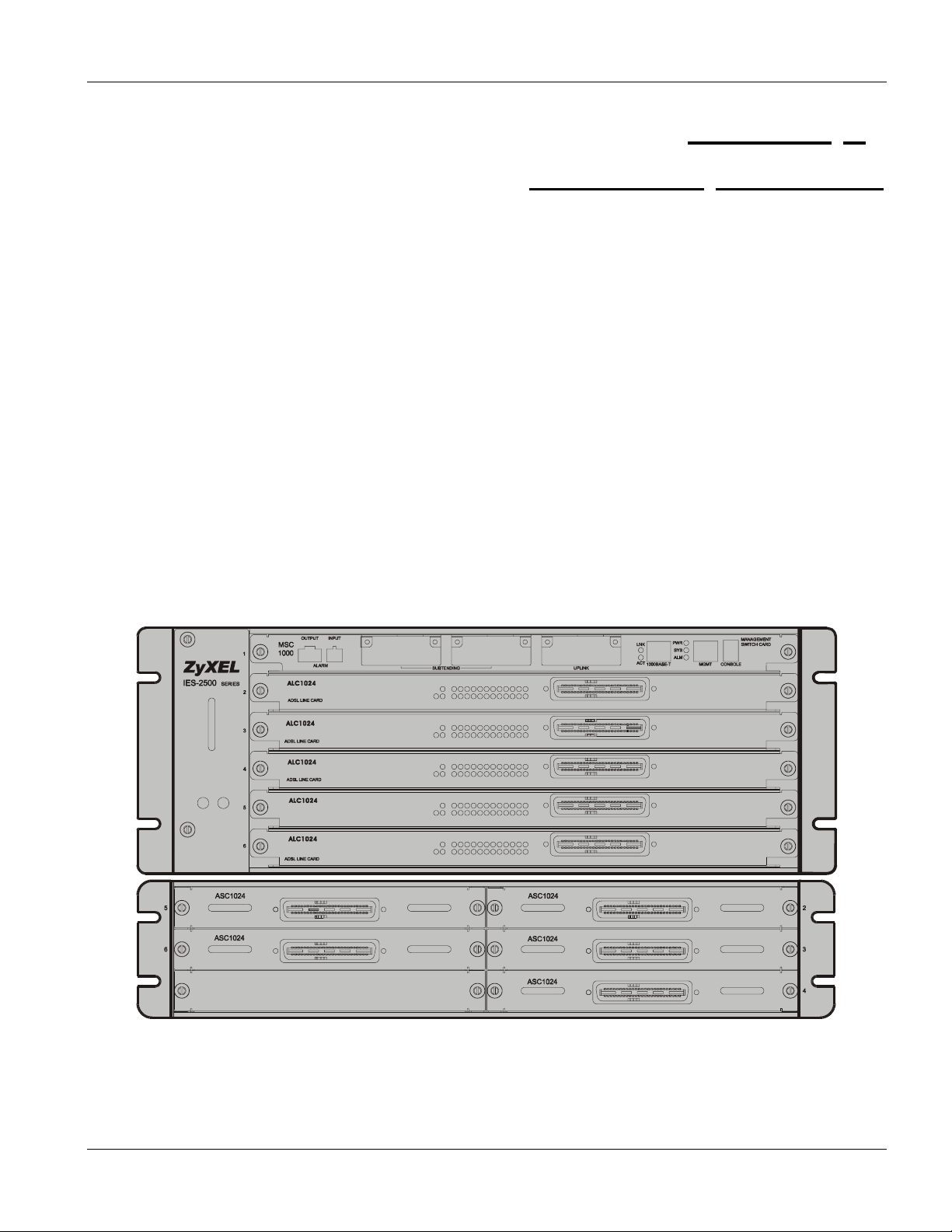
1.1 Front Panel
The following figure shows the front panels of the IES-2500 main chassis and IES-2000 splitter chassis with
installed line and splitter cards.
Figure 1-1 IES-2500 Front Panel
Card Installation 1-1
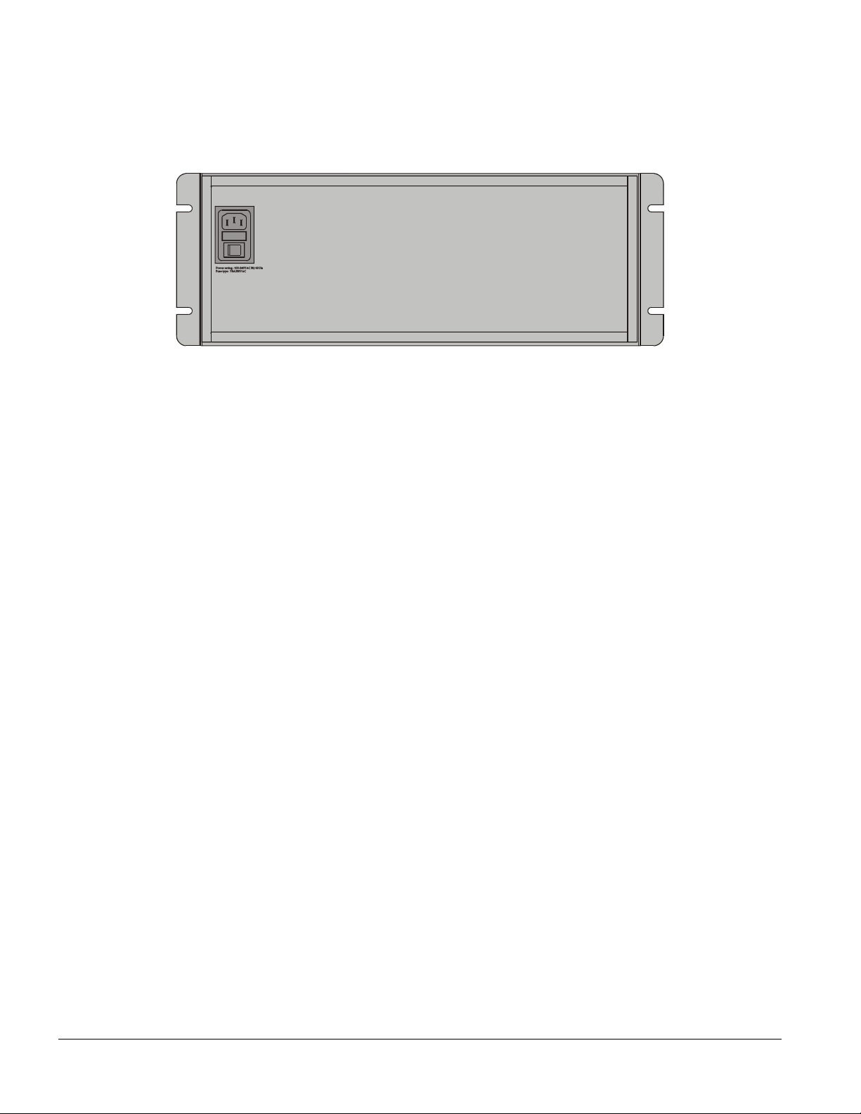
1.2 Back Panel
The following figure shows the back panel of the IES-2500 main chassis.
Figure 1-2 IES 2500 Back Panel
1.3 Features
Main Chassis
The main chassis has slots for hot-swappable DSL line cards and a management switch card.
Splitter Chassis
The splitter chassis has slots for hot-swappable splitter and extension cards, and Telco-50 connectors or wire
wrapping pins for connecting to the subscribers and the PBX (Private Branch Exchange) or PSTN/ISDN (Public
Switched Telephone Network)(Integrated Services Digital Network) switch.
Hot Swappable DSL Line Cards
The IES-2500 uses hot swappable DSL line cards.
Hot Swappable Splitter Cards
The IES-2500 uses hot swappable splitter cards.
Management Switch Card
The IES-2500 accommodates a management switch card that switches traffic and forwards it between the DSL line
cards and other Ethernet switches.
Hot Swappable Fan Module
The IES-2500 is equipped with a hot swappable fan module to provide easy maintenance, greater reliability and
increased system operating lifetimes.
Power Module
You can easily access the IES-2500’s power module, located on the upper left side of the rear panel, to change a
fuse.
Scalable Platform for Future Expansion
1-2 Card Installation
IES-2500 User’s Guide
The flexible design of the IES-2500 allows service providers to start with minimum cost. As the number of users
and applications increases, additional DSL line cards can be added to support more subscribers.
1.4 Applications
The following sections describe example applications for the IES-2500. This figure gives an example overview.
Figure 1-3 Application Overview Example
1.4.1 IP DSLAM
The IES-2500 operates as an IP DSLAM in a telephone company’s central office. It provides DSL service over
telephone wires to subscribers. The following figure shows the IES-2500 set up in a telephone company’s central
office.
Card Installation 1-3

Figure 1-4 IP DSLAM Application Example
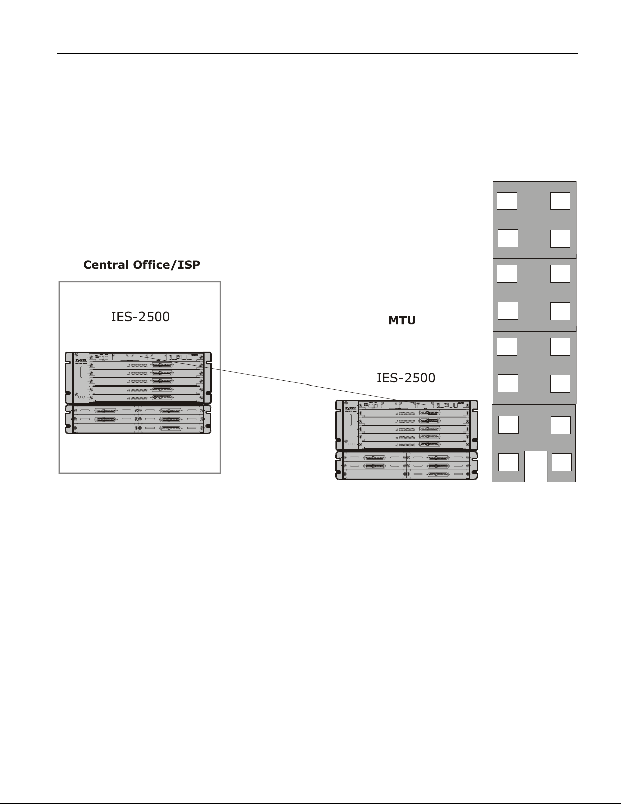
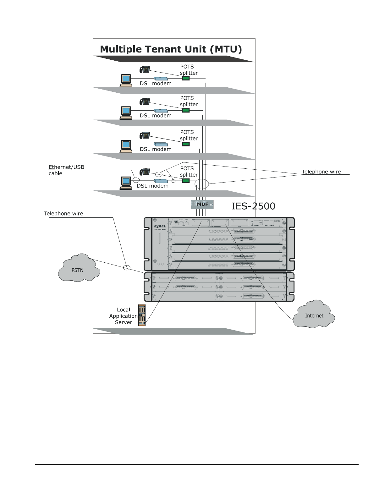
1.4.2 MTU Application
The following figure depicts a typical application of the IES-2500 in a large residential building, or multiple tenant
unit (MTU), that leverages the existing phone line wiring to provide Internet access to subscribers in the building.
A subscriber connects a computer to the phone line in a unit using an ADSL modem. The other end of the phone
line is connected to a port on the IES-2500. The IES-2500 aggregates the traffic from subscribers and then forwards
it through an Ethernet connection to the Internet.
1-4 Card Installation
IES-2500 User’s Guide
Figure 1-5 MTU Application Example
Card Installation 1-5

 Loading...