

Page 1

Dimension
ES-4024
Ethernet Switch
March 2004
Version 3.50
User’s Guide
Page 2

Page 3

Dimension ES-4024 Ethernet Switch
Copyright
Copyright © 2004 by ZyXEL Communications Corporation
The contents of this publication may not be reproduced in any part or as a whole, transcribed, stored in a retrieval
system, translated into any language, or transmitted in any form or by any means, electronic, mechanical,
magnetic, optical, chemical, photocopying, manual, or otherwise, without the prior written permission of ZyXEL
Communications Corporation.
Published by ZyXEL Communications Corporation. All rights reserved.
Disclaimer
ZyXEL does not assume any liability arising out of the application or use of any products, or software described
herein. Neither does it convey any license under its patent rights nor the patents rights of others. ZyXEL further
reserves the right to make changes in any products described herein without notice. This publication is subject to
change without notice.
Trademarks
Trademarks mentioned in this publication are used for identification purposes only and may be properties of their
respective owners.
Copyright iii
Page 4

Dimension ES-4024 Ethernet Switch
ZyXEL Limited Warranty
ZyXEL warrants to the original end user (purchaser) that this product is free from any defects in materials or
workmanship for a period of up to two (2) years from the date of purchase. During the warranty period and upon
proof of purchase, should the product have indications of failure due to faulty workmanship and/or materials,
ZyXEL will, at its discretion, repair or replace the defective products or components without charge for either
parts or labor and to whatever extent it shall deem necessary to restore the product or components to proper
operating condition. Any replacement will consist of a new or re-manufactured functionally equivalent product of
equal value, and will be solely at the discretion of ZyXEL. This warranty shall not apply if the product is
modified, misused, tampered with, damaged by an act of God, or subjected to abnormal working conditions.
Note
Repair or replacement, as provided under this warranty, is the exclusive remedy of the purchaser. This warranty is
in lieu of all other warranties, express or implied, including any implied warranty of merchantability or fitness for
a particular use or purpose. ZyXEL shall in no event be held liable for indirect or consequential damages of any
kind of character to the purchaser.
To obtain the services of this warranty, contact ZyXEL's Service Center for your Return Material Authorization
number (RMA). Products must be returned Postage Prepaid. It is recommended that the unit be insured when
shipped. Any returned products without proof of purchase or those with an out-dated warranty will be repaired or
replaced (at the discretion of ZyXEL) and the customer will be billed for parts and labor. All repaired or replaced
products will be shipped by ZyXEL to the corresponding return address, Postage Paid. This warranty gives you
specific legal rights, and you may also have other rights that vary from country to country.
iv ZyXEL Limited Warranty
Page 5

Dimension ES-4024 Ethernet Switch
Interference Statements and Warnings
FCC Interference Statement
This switch complies with Part 15 of the FCC rules. Operation is subject to the following two conditions:
(1) This switch may not cause harmful interference.
(2) This switch must accept any interference received, including interference that may cause undesired operations.
FCC Warning
This equipment has been tested and found to comply with the limits for a Class A digital switch, pursuant to Part
15 of the FCC Rules. These limits are designed to provide reasonable protection against harmful interference in a
commercial environment. This equipment generates, uses, and can radiate radio frequency energy and, if not
installed and used in accordance with the instruction manual, may cause harmful interference to radio
communications. Operation of this equipment in a residential area is likely to cause harmful interference in which
case the user will be required to correct the interference at his own expense.
CE Mark Warning:
This is a class A product. In a domestic environment this product may cause radio interference in which case the
user may be required to take adequate measures.
Taiwanese BSMI (Bureau of Standards, Metrology and Inspection) A Warning:
Certifications
Refer to the product page at www.zyxel.com.
Interference Statements and Warnings v
Page 6
Dimension ES-4024 Ethernet Switch
Customer Support
If you have questions about your ZyXEL product or desire assistance, contact ZyXEL Communications
Corporation offices worldwide, in one of the following ways:
Contacting Customer Support
When you contact your customer support representative, have the following information ready:
♦ Product model and serial number.
♦ Firmware version information.
♦ Warranty information.
♦ Date you received your product.
♦ Brief description of the problem and the steps you took to solve it.
SUPPORT E-MAIL TELEPHONE1 WEB SITE METHOD
LOCATION
WORLDWIDE
FINLAND support@zyxel.fi +358-9-4780-8411 www.zyxel.fi ZyXEL Communications Oy
SALES E-MAIL FAX1 FTP SITE
support@zyxel.com.tw +886-3-578-3942 www.zyxel.com
sales@zyxel.com.tw
support@zyxel.com +1-800-255-4101
sales@zyxel.com
support@zyxel.de +49-2405-6909-0 www.zyxel.de GERMANY
sales@zyxel.de
support@zyxel.es +34 902 195 420 SPAIN
sales@zyxel.es
support@zyxel.dk +45 39 55 07 00 www.zyxel.dk DENMARK
sales@zyxel.dk
support@zyxel.no +47 22 80 61 80 www.zyxel.no NORWAY
sales@zyxel.no
support@zyxel.se +46 31 744 7700 www.zyxel.se SWEDEN
sales@zyxel.se
+886-3-578-2439 ftp.europe.zyxel.com
+1-714-632-0882
+1-714-632-0858 ftp.us.zyxel.com
+49-2405-6909-99
+33 (0)4 72 52 97 97 FRANCE info@zyxel.fr
+33 (0)4 72 52 19 20
+34 913 005 345
+45 39 55 07 07
+47 22 80 61 81
+46 31 744 7701
www.europe.zyxel.com
ftp.zyxel.com
www.us.zyxel.com NORTH AMERICA
www.zyxel.fr ZyXEL France
www.zyxel.es
ZyXEL Communications
ZyXEL Communications Corp.
6 Innovation Road II
Science Park
Hsinchu 300
Taiwan
ZyXEL Communications Inc.
1130 N. Miller St.
Anaheim
CA 92806-2001
U.S.A.
ZyXEL Deutschland GmbH. Adenauerstr.
20/A2 D-52146
Wuerselen
Germany
1 rue des Vergers
Bat. 1 / C
69760 Limonest
France
Alejandro Villegas 33
1º, 28043 Madrid
Spain
ZyXEL Communications A/S
Columbusvej 5
2860 Soeborg
Denmark
ZyXEL Communications A/S
Nils Hansens vei 13
0667 Oslo
Norway
ZyXEL Communications A/S
Sjöporten 4, 41764 Göteborg
Sweden
Malminkaari 10
00700 Helsinki
Finland
REGULAR MAIL
1
“+” is the (prefix) number you enter to make an international telephone call.
vi Customer Support
Page 7

Dimension ES-4024 Ethernet Switch
Table of Contents
Copyright .................................................................................................................................................................. iii
ZyXEL Limited Warranty...........................................................................................................................................iv
Interference Statements and Warnings.....................................................................................................................v
Customer Support ....................................................................................................................................................vi
List of Figures ..........................................................................................................................................................xii
List of Tables.......................................................................................................................................................... xvii
Preface ....................................................................................................................................................................xx
Features And Applications......................................................................................................................................... I
Chapter 1 Getting to Know the ES-4024........................................................................................................ 1-1
1.1 Features ................................................................................................................................................ 1-1
1.2 Applications ........................................................................................................................................... 1-3
Hardware Installation and Connections................................................................................................................... II
Chapter 2 Hardware Installation..................................................................................................................... 2-1
2.1 Installation Scenarios ............................................................................................................................ 2-1
Chapter 3 Hardware Connections.................................................................................................................. 3-1
3.1 Safety Warnings .................................................................................................................................... 3-1
3.2 Front Panel ............................................................................................................................................ 3-1
3.3 Stacking Module .................................................................................................................................... 3-2
3.4 Rear Panel............................................................................................................................................. 3-2
3.5 Front Panel LEDs .................................................................................................................................. 3-3
3.6 Stacking Scenario Examples................................................................................................................. 3-4
3.7 Uplink Scenario Example ...................................................................................................................... 3-6
3.8 Accessing the ES-4024 ......................................................................................................................... 3-7
Getting Started .......................................................................................................................................................... III
Chapter 4 Introducing the Web Configurator ................................................................................................. 4-1
4.1 Introduction............................................................................................................................................ 4-1
4.2 System Login......................................................................................................................................... 4-1
4.3 The Status Screen................................................................................................................................. 4-1
4.4 Switch Lockout ...................................................................................................................................... 4-6
4.5 Resetting the Switch.............................................................................................................................. 4-7
Chapter 5 System Status and Port Statistics.................................................................................................. 5-1
5.1 About System Statistics and Information .............................................................................................. 5-1
5.2 Port Status Summary ............................................................................................................................ 5-1
Chapter 6 Basic Setting.................................................................................................................................. 6-1
Table of Contents vii
Page 8

Dimension ES-4024 Ethernet Switch
6.1 Introducing The Basic Setting Screens .................................................................................................6-1
6.2 System Information................................................................................................................................ 6-1
6.3 General Setup........................................................................................................................................ 6-3
6.4 Introduction to VLANs............................................................................................................................ 6-4
6.5 IGMP Snooping .....................................................................................................................................6-5
6.6 Switch Setup Screen .............................................................................................................................6-5
6.7 IP Setup .................................................................................................................................................6-7
6.8 Port Setup............................................................................................................................................6-10
Advanced Application...............................................................................................................................................IV
Chapter 7 VLAN..............................................................................................................................................7-1
7.1 Introduction to IEEE 802.1Q Tagged VLAN .......................................................................................... 7-1
7.2 Introduction to Port-based VLANs ......................................................................................................... 7-9
Chapter 8 Static MAC Forward Setup ............................................................................................................ 8-1
8.1 Introduction to Static MAC Forward Setup ............................................................................................ 8-1
8.2 Configuring Static MAC Forwarding ...................................................................................................... 8-1
8.3 Viewing and Editing Static MAC Forwarding Rules............................................................................... 8-2
Chapter 9 Filtering .......................................................................................................................................... 9-1
9.1 Introduction to Filtering ..........................................................................................................................9-1
9.2 Configuring a Filtering Rule ...................................................................................................................9-1
9.3 Viewing and Editing Filter Rules............................................................................................................ 9-4
Chapter 10 Spanning Tree Protocol ............................................................................................................... 10-1
10.1 Introduction to Spanning Tree Protocol (STP) ....................................................................................10-1
10.2 STP Status........................................................................................................................................... 10-2
Chapter 11 Bandwidth Control ....................................................................................................................... 11-1
11.1 Introduction to Bandwidth Control .......................................................................................................11-1
11.2 Viewing and Editing a Bandwidth Control Rule ................................................................................... 11-5
Chapter 12 Broadcast Storm Control .............................................................................................................12-1
12.1 Introducing Broadcast Storm Control ..................................................................................................12-1
12.2 Configuring Broadcast Storm Control.................................................................................................. 12-1
Chapter 13 Mirroring....................................................................................................................................... 13-1
13.1 Introduction to Port Mirroring ...............................................................................................................13-1
13.2 Port Mirroring Configuration ................................................................................................................13-1
Chapter 14 Link Aggregation .......................................................................................................................... 14-1
14.1 Introduction to Link Aggregation..........................................................................................................14-1
14.2 Link Aggregation Configuration ........................................................................................................... 14-2
14.3 Link Aggregation Setup .......................................................................................................................14-3
viii Table of Contents
Page 9

Dimension ES-4024 Ethernet Switch
Chapter 15 Port Authentication ...................................................................................................................... 15-1
15.1 Introduction to Authentication.............................................................................................................. 15-1
15.2 Configuring Port Authentication........................................................................................................... 15-1
Chapter 16 Port Security ................................................................................................................................ 16-1
16.1 About Port Security ............................................................................................................................. 16-1
16.2 Port Security Setup ............................................................................................................................. 16-1
Chapter 17 DHCP .......................................................................................................................................... 17-1
17.1 About DHCP ........................................................................................................................................ 17-1
17.2 Configuring DHCP............................................................................................................................... 17-1
17.3 Viewing and Editing DHCP Settings.................................................................................................... 17-3
Chapter 18 Access Control ............................................................................................................................ 18-1
18.1 Access Control Overview .................................................................................................................... 18-1
18.2 The Access Control Main Screen........................................................................................................ 18-1
18.3 About SNMP........................................................................................................................................ 18-2
18.4 Service Access Control ....................................................................................................................... 18-6
18.5 Remote Management.......................................................................................................................... 18-6
Chapter 19 Differentiated Services ................................................................................................................ 19-1
19.1 Introduction to DiffServ........................................................................................................................ 19-1
19.2 Activating DiffServ ............................................................................................................................... 19-2
19.3 Configuring Marking Rules .................................................................................................................. 19-4
19.4 DSCP-to-IEEE802.1p Priority Mapping............................................................................................... 19-6
Chapter 20 Queuing Method.......................................................................................................................... 20-1
20.1 Introduction to Queuing ....................................................................................................................... 20-1
20.2 Configuring Queuing ........................................................................................................................... 20-1
Chapter 21 VRRP........................................................................................................................................... 21-1
21.1 VRRP Overview................................................................................................................................... 21-1
21.2 Viewing VRRP Status.......................................................................................................................... 21-2
21.3 Configuring VRRP ............................................................................................................................... 21-3
21.4 VRRP Configuration Summary............................................................................................................ 21-7
21.5 VRRP Configuration Examples ........................................................................................................... 21-8
Routing Protocol ........................................................................................................................................................V
Chapter 22 Static Route ................................................................................................................................. 22-1
22.1 Configuring Static Routes.................................................................................................................... 22-1
Chapter 23 RIP............................................................................................................................................... 23-1
23.1 Overview.............................................................................................................................................. 23-1
23.2 Configuring RIP ................................................................................................................................... 23-1
Table of Contents ix
Page 10

Dimension ES-4024 Ethernet Switch
Chapter 24 IGMP............................................................................................................................................ 24-1
24.1 Overview..............................................................................................................................................24-1
24.2 Configuring IGMP ................................................................................................................................ 24-1
Chapter 25 DVMRP........................................................................................................................................ 25-1
25.1 Introduction to DVMRP........................................................................................................................ 25-1
25.2 How DVMRP Works ............................................................................................................................25-1
25.3 Configuring DVMRP ............................................................................................................................25-2
25.4 Default DVMRP Timer Values .............................................................................................................25-3
Chapter 26 OSPF ........................................................................................................................................... 26-1
26.1 OSPF Overview ................................................................................................................................... 26-1
26.2 OSPF Status........................................................................................................................................26-3
26.3 Enabling OSPF and General Settings................................................................................................. 26-5
26.4 Configuring OSPF Areas .....................................................................................................................26-6
26.5 Configuring OSPF Interfaces............................................................................................................... 26-8
26.6 Configuring OSPF Virtual Links...........................................................................................................26-9
Management...............................................................................................................................................................VI
Chapter 27 Maintenance ................................................................................................................................ 27-1
27.1 Maintenance ........................................................................................................................................ 27-1
27.2 Firmware Upgrade ............................................................................................................................... 27-1
27.3 Restore a Configuration File................................................................................................................27-2
27.4 Backing Up a Configuration File .......................................................................................................... 27-2
27.5 Load Factory Defaults .........................................................................................................................27-3
27.6 Reboot System .................................................................................................................................... 27-3
27.7 FTP Command Line.............................................................................................................................27-4
Chapter 28 Diagnostic .................................................................................................................................... 28-1
28.1 Diagnostic ............................................................................................................................................28-1
Chapter 29 Cluster Management ...................................................................................................................29-1
29.1 Introduction to Cluster Management ...................................................................................................29-1
29.2 Cluster Management Status ................................................................................................................29-2
29.3 Configuring Cluster Management........................................................................................................29-4
Chapter 30 MAC Table ...................................................................................................................................30-1
30.1 Introduction to MAC Table...................................................................................................................30-1
30.2 Viewing the MAC Table .......................................................................................................................30-2
Chapter 31 IP Table ........................................................................................................................................ 31-1
31.1 Introduction to IP Table .......................................................................................................................31-1
31.2 Viewing the IP Table............................................................................................................................ 31-2
x Table of Contents
Page 11

Dimension ES-4024 Ethernet Switch
Chapter 32 ARP Table.................................................................................................................................... 32-1
32.1 Introduction to ARP Table ................................................................................................................... 32-1
32.2 Viewing ARP Table ............................................................................................................................. 32-1
Chapter 33 Routing Table............................................................................................................................... 33-1
33.1 About the Routing Table...................................................................................................................... 33-1
33.2 Viewing the Routing Table .................................................................................................................. 33-1
Chapter 34 DHCP Server Status.................................................................................................................... 34-1
34.1 About DHCP Server Status ................................................................................................................. 34-1
34.2 Displaying DHCP Server Status.......................................................................................................... 34-1
34.3 Displaying Detail DHCP Server Information........................................................................................ 34-2
Commands................................................................................................................................................................ VII
Chapter 35 Introduction to CLI ....................................................................................................................... 35-1
35.1 Command Line Interface Overview..................................................................................................... 35-1
35.2 Command Summary ........................................................................................................................... 35-2
Chapter 36 Command Examples ................................................................................................................... 36-1
36.1 Commonly Used Commands Overview ..............................................................................................36-1
36.2 sys Commands.................................................................................................................................... 36-1
36.3 ipCommands ....................................................................................................................................... 36-4
Chapter 37 IEEE 802.1Q Tagged VLAN ........................................................................................................ 37-1
37.1 IEEE 802.1Q Tagged VLAN Overview................................................................................................ 37-1
37.2 Filtering Databases ............................................................................................................................. 37-1
37.3 Configuring Tagged VLAN .................................................................................................................. 37-1
37.4 IEEE VLAN1Q Tagged VLAN Configuration Commands ...................................................................37-3
37.5 sys sw vlan1q svlan active .................................................................................................................. 37-8
37.6 sys sw vlan1q svlan inactive ............................................................................................................... 37-8
37.7 sys sw vlan1q svlan list ....................................................................................................................... 37-8
37.8 sys sw vlan1q vlan list ......................................................................................................................... 37-9
Appendix and Index ................................................................................................................................................ VIII
Appendix A Product Specifications........................................................................................................................... A
Index......................................................................................................................................................................... E
Table of Contents xi
Page 12

Dimension ES-4024 Ethernet Switch
List of Figures
Figure 1-1 Backbone Application............................................................................................................................... 1-4
Figure 1-2 Bridging Application..................................................................................................................................1-5
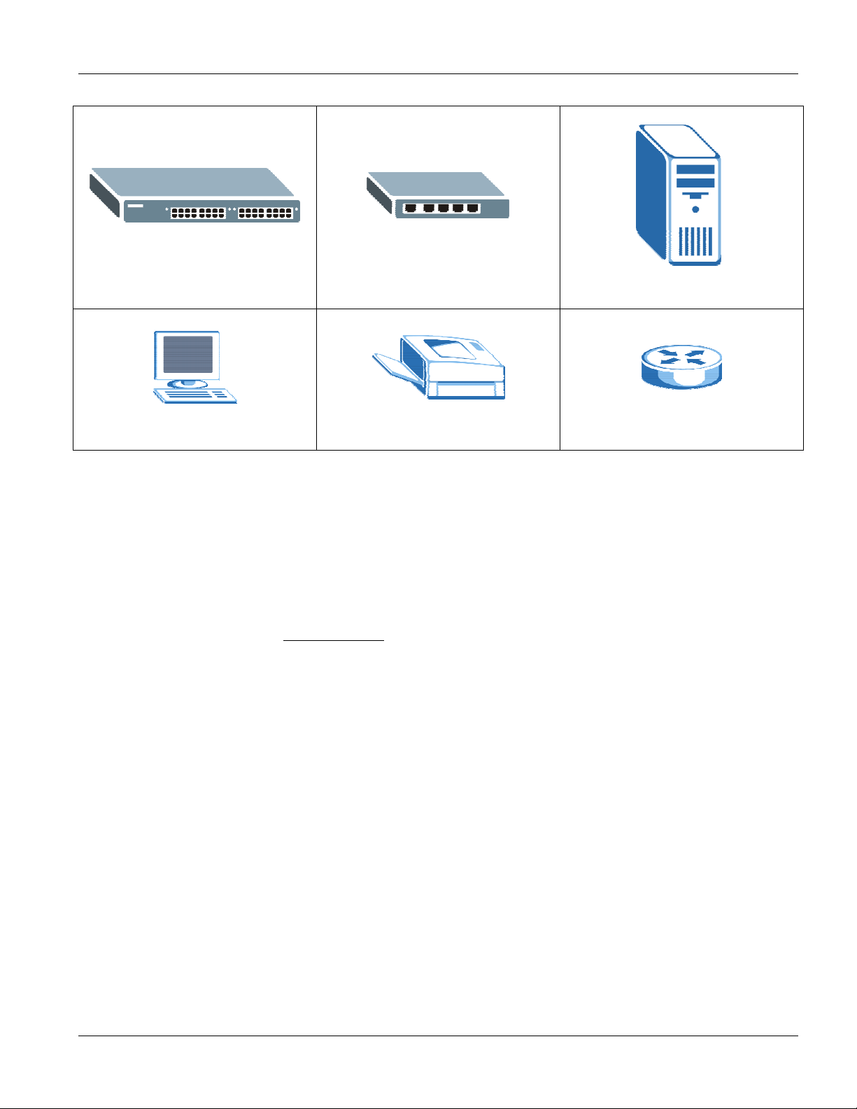
Figure 1-3 High Performance Switched Workgroup Application ............................................................................... 1-5
Figure 1-4 VLAN Workgroup Application................................................................................................................... 1-6
Figure 1-5 Shared Server Using VLAN Example ...................................................................................................... 1-6
Figure 2-1 Attaching Rubber Feet .............................................................................................................................2-1
Figure 2-2 Attaching Mounting Brackets and Screws................................................................................................2-2
Figure 2-3 Mounting the ES to an EIA standard 19-inch rack ................................................................................... 2-2
Figure 3-1 ES-4024 Front Panel................................................................................................................................3-1
Figure 3-2 ES-4024 Rear Panel: AC model .............................................................................................................. 3-2
Figure 3-3 ES-4024 Rear Panel: DC Model ..............................................................................................................3-3
Figure 3-4 Front Panel LEDs..................................................................................................................................... 3-3
Figure 3-5 Stacking Example 1..................................................................................................................................3-5
Figure 3-6 Stacking Example 2..................................................................................................................................3-5
Figure 3-7 Stacking Example 3..................................................................................................................................3-6
Figure 3-8 Uplink Example ........................................................................................................................................ 3-7
Figure 4-1 Web Configurator: login ........................................................................................................................... 4-1
Figure 4-2 Web Configurator Home Screen (Status) ................................................................................................4-2
Figure 4-3 Change Administrator Login Password.................................................................................................... 4-6
Figure 4-4 Resetting the Switch: Via Console Port ................................................................................................... 4-8
Figure 4-5 Web Configurator: Logout Screen ...........................................................................................................4-8
Figure 5-1 Status .......................................................................................................................................................5-1
Figure 5-2 Status: Port Details...................................................................................................................................5-3
Figure 6-1 Basic Setting: System Info ....................................................................................................................... 6-1
Figure 6-2 Basic Setting: General Setup................................................................................................................... 6-3
Figure 6-3 Basic Setting: Switch Setup ..................................................................................................................... 6-5
Figure 6-4 Basic Setting: IP Setup: Default Gateway and Domain Name Server..................................................... 6-8
Figure 6-5 IP Setup: Configure IP Routing Domains.................................................................................................6-9
Figure 6-6 IP Setup: View Settings..........................................................................................................................6-10
Figure 6-7 Basic Setting: Port Setup ....................................................................................................................... 6-11
Figure 7-1 Port VLAN Trunking ................................................................................................................................. 7-3
Figure 7-2 Switch Setup: VLAN Type........................................................................................................................ 7-3
Figure 7-3 Advanced: VLAN Status ...........................................................................................................................7-4
Figure 7-4 VLAN: VLAN Port Setting ........................................................................................................................7-5
xii Lists of Figures
Page 13

Dimension ES-4024 Ethernet Switch
Figure 7-5 VLAN: Static VLAN .................................................................................................................................. 7-7
Figure 7-6 Static VLAN: Summary Table................................................................................................................... 7-8
Figure 7-7 Port Based VLAN Setup (All Connected) .............................................................................................. 7-10
Figure 7-8 Port Based VLAN Setup (Port Isolation)................................................................................................ 7-11
Figure 8-1 Advanced: Static MAC Forwarding ..........................................................................................................8-1
Figure 8-2 Static MAC Forwarding: Summary Table................................................................................................. 8-2
Figure 9-1 Filtering .................................................................................................................................................... 9-2
Figure 9-2 Filtering: Summary Table ......................................................................................................................... 9-4
Figure 10-1 Spanning Tree Protocol: Status ........................................................................................................... 10-2
Figure 10-2 Spanning Tree Protocol: Configuration................................................................................................ 10-4
Figure 11-1 Advanced: Bandwidth Control.............................................................................................................. 11-2
Figure 11-2 VLAN Bandwidth Control Example ...................................................................................................... 11-5
Figure 11-3 Bandwidth Control: Summary Table..................................................................................................... 11-6
Figure 12-1 Broadcast Storm Control...................................................................................................................... 12-2
Figure 13-1 Mirroring: Mirror Port Setting ............................................................................................................... 13-2
Figure 13-2 Mirroring: Configuration ....................................................................................................................... 13-4
Figure 13-3 Mirroring: Summary Table.................................................................................................................... 13-6
Figure 14-1 Link Aggregation ID..............................................................................................................................14-2
Figure 14-2 Link Aggregation Control Protocol Status ............................................................................................ 14-3
Figure 14-3 Link Aggregation: Configuration........................................................................................................... 14-4
Figure 15-1 RADIUS Server.................................................................................................................................... 15-1
Figure 15-2 Port Authentication............................................................................................................................... 15-2
Figure 15-3 Port Authentication: 802.1x.................................................................................................................. 15-3
Figure 15-4 Port Authentication: RADIUS............................................................................................................... 15-4
Figure 16-1 Port Security ........................................................................................................................................ 16-2
Figure 17-1 DHCP................................................................................................................................................... 17-2
Figure 17-2 DHCP: Summary Table........................................................................................................................ 17-3
Figure 18-1 Console Port Priority............................................................................................................................ 18-1
Figure 18-2 Access Control..................................................................................................................................... 18-1
Figure 18-3 SNMP Management Model.................................................................................................................. 18-2
Figure 18-4 Access Control: SNMP ........................................................................................................................ 18-4
Figure 18-5 Access Control: Logins ........................................................................................................................ 18-5
Figure 18-6 Access Control: Service Access Control.............................................................................................. 18-6
Figure 18-7 Access Control: Remote Management................................................................................................ 18-7
Figure 19-1 DiffServ: Differentiated Service Field................................................................................................... 19-1
Figure 19-2 DiffServ Network Example................................................................................................................... 19-2
Lists of Figures xiii
Page 14

Dimension ES-4024 Ethernet Switch
Figure 19-3 Advanced Applications: DiffServ ..........................................................................................................19-3
Figure 19-4 DiffServ: Marking Rule Setting............................................................................................................. 19-4
Figure 19-5 DiffServ: Marking Rule Summary......................................................................................................... 19-6
Figure 19-6 DiffServ: DSCP Setting ........................................................................................................................ 19-7
Figure 20-1 Queuing Method...................................................................................................................................20-2
Figure 21-1 VRRP: Example 1 ................................................................................................................................ 21-1
Figure 21-2 VRRP Status ........................................................................................................................................ 21-2
Figure 21-3 VRRP Configuration: IP Interface ........................................................................................................ 21-4
Figure 21-4 VRRP Configuring: VRRP Parameters................................................................................................ 21-6
Figure 21-5 VRRP Configuration: Summary ........................................................................................................... 21-7
Figure 21-6 VRRP Configuration Example: One Virtual Router Network ...............................................................21-8
Figure 21-7 VRRP Example 1: VRRP Parameter Settings on Switch A .................................................................21-8
Figure 21-8 VRRP Example 1: VRRP Parameter Settings on Switch B................................................................. 21-9
Figure 21-9 VRRP Example 1: VRRP Status on Switch A ...................................................................................... 21-9
Figure 21-10 VRRP Example 1: VRRP Status on Switch B .................................................................................... 21-9
Figure 21-11 VRRP Configuration Example: Two Virtual Router Network ............................................................21-10
Figure 21-12 VRRP Example 2: VRRP Parameter Settings for VR2 on Switch A................................................ 21-10
Figure 21-13 VRRP Example 2: VRRP Parameter Settings for VR2 on Switch B................................................ 21-11
Figure 21-14 VRRP Example 2: VRRP Status on Switch A .................................................................................. 21-11
Figure 21-15 VRRP Example 2: VRRP Status on Switch B .................................................................................. 21-11
Figure 22-1 Static Routing.......................................................................................................................................22-1
Figure 22-2 Static Routing: Summary Table............................................................................................................22-2
Figure 23-1 RIP .......................................................................................................................................................23-1
Figure 24-1 IGMP ....................................................................................................................................................24-1
Figure 25-1 How DVMRP Works............................................................................................................................. 25-1
Figure 25-2 DVMRP ................................................................................................................................................ 25-2
Figure 25-3 IGMP Not Set Error.............................................................................................................................. 25-3
Figure 25-4 Unable to Disable IGMP Error .............................................................................................................25-3
Figure 25-5 No Duplicate VID Error Message.........................................................................................................25-3
Figure 26-1 OSPF vs. RIP.......................................................................................................................................26-1
Figure 26-2 OSPF Network Example ...................................................................................................................... 26-2
Figure 26-3 OSPF Status ........................................................................................................................................ 26-3
Figure 26-4 OSPF Configuration: Activating and General Settings ........................................................................26-5
Figure 26-5 OSPF Configuration: Area Setup ......................................................................................................... 26-7
Figure 26-6 OSPF Configuration: Summary Table.................................................................................................. 26-8
Figure 26-7 OSPF Interface ....................................................................................................................................26-9
xiv Lists of Figures
Page 15

Dimension ES-4024 Ethernet Switch
Figure 26-8 OSPF Virtual Link .............................................................................................................................. 26-10
Figure 26-9 OSPF Virtual Link: Summary Table ................................................................................................... 26-11
Figure 27-1 Maintenance ........................................................................................................................................ 27-1
Figure 27-2 Firmware Upgrade ............................................................................................................................... 27-1
Figure 27-3 Restore Configuration.......................................................................................................................... 27-2
Figure 27-4 Backup Configuration .......................................................................................................................... 27-2
Figure 27-5 Load Factory Default: Conformation.................................................................................................... 27-3
Figure 27-6 Load Factory Default: Start.................................................................................................................. 27-3
Figure 27-7 Reboot System: Confirmation.............................................................................................................. 27-3
Figure 27-8 Reboot System: Start........................................................................................................................... 27-4
Figure 28-1 Diagnostic ............................................................................................................................................ 28-1
Figure 29-1 Clustering Application Example ........................................................................................................... 29-1
Figure 29-2 Cluster Management: Status ............................................................................................................... 29-2
Figure 29-3 Cluster Member Web Configuration Screen........................................................................................ 29-3
Figure 29-4 Example: Uploading Firmware to a Cluster Member Switch ............................................................... 29-4
Figure 29-5 Clustering Management Configuration ................................................................................................ 29-5
Figure 30-1 MAC Table Flowchart........................................................................................................................... 30-1
Figure 30-2 Filtering Database................................................................................................................................ 30-2
Figure 31-1 IP Table Flowchart ............................................................................................................................... 31-1
Figure 31-2 Management: IP Table ......................................................................................................................... 31-2
Figure 32-1 ARP Table ............................................................................................................................................ 32-2
Figure 33-1 Management: Routing Table Status..................................................................................................... 33-1
Figure 34-1 Management: DHCP Server Status ..................................................................................................... 34-1
Figure 34-2 DHCP Server Status Detail.................................................................................................................. 34-2
Figure 35-1 CLI Help: Sample Output..................................................................................................................... 35-2
Figure 36-1 sys log disp Command Example ......................................................................................................... 36-1
Figure 36-2 sys version Command Example .......................................................................................................... 36-2
Figure 36-3 sys monitor status Command Example ............................................................................................... 36-2
Figure 36-4 sys sw vlan1q vlan list Command Example......................................................................................... 36-3
Figure 36-5 sys ixe2424 pktcnt Command Example .............................................................................................. 36-3
Figure 36-6 sys ixe2424 dbm ip list Command Example........................................................................................ 36-4
Figure 36-7 sys ixe2424 dbm mac list Command Example.................................................................................... 36-4
Figure 36-8 ip ping Command Example.................................................................................................................. 36-4
Figure 36-9 ip route status Command Example...................................................................................................... 36-5
Figure 36-10 ip rtDomain display Command Example ........................................................................................... 36-5
Figure 36-11 ip rtDomain add Command Example ................................................................................................. 36-5
Lists of Figures xv
Page 16

Dimension ES-4024 Ethernet Switch
Figure 36-12 ip rtDomain delete Command Example ............................................................................................. 36-6
Figure 36-13 ip arp status Command Example....................................................................................................... 36-6
Figure 37-1 Tagged VLAN Configuration and Activation Example..........................................................................37-2
Figure 37-2 CPU VLAN Configuration and Activation Example..............................................................................37-2
Figure 37-3 Deleting Default VLAN Example .......................................................................................................... 37-3
Figure 37-4 sys sw garp status Command Example............................................................................................... 37-3
Figure 37-5 sys sw garp timer Command Example ................................................................................................37-4
Figure 37-6 sys sw gvrp status Command Example............................................................................................... 37-4
Figure 37-7 sys sw vlan1q port status Command Example .................................................................................... 37-5
Figure 37-8 sys sw vlan1q port defaultVID Command Example............................................................................. 37-5
Figure 37-9 sys sw vlan1q port accept Command Example ................................................................................... 37-6
Figure 37-10 sys sw vlan1q port gvrp Command Example..................................................................................... 37-6
Figure 37-11 sys sw vlan1q svlan cpu Command Example.................................................................................... 37-6
Figure 37-12 Modifying the Static VLAN Example .................................................................................................. 37-7
Figure 37-13 VLAN1Q SVLAN DELENTRY Command Example........................................................................... 37-8
Figure 37-14 sys sw vlan1q svlan list Command Example ..................................................................................... 37-9
Figure 37-15 sys sw vlan1q vlan list Command Example.....................................................................................37-10
Figure 37-16 sys sw vlan1q vlan status Command Example................................................................................37-10
xvi Lists of Figures
Page 17

Dimension ES-4024 Ethernet Switch
List of Tables
Table 3-1 ES-4024 Front Panel ................................................................................................................................. 3-1
Table 3-2 Front Panel: LED Descriptions .................................................................................................................. 3-3
Table 4-1 Navigation Panel Sub-links Overview ....................................................................................................... 4-3
Table 4-2 Web Configurator Screen Sub-links Details .............................................................................................. 4-3
Table 4-3 Navigation Panel Links .............................................................................................................................. 4-4
Table 5-1 Status......................................................................................................................................................... 5-2
Table 5-2 Status: Port Details.................................................................................................................................... 5-3
Table 6-1 Basic Setting: System Info ........................................................................................................................ 6-2
Table 6-2 Basic Setting: General Setup .................................................................................................................... 6-3
Table 6-3 Basic Setting: Switch Setup ...................................................................................................................... 6-6
Table 6-4 Basic Setting: IP Setup: Default Gateway and Domain Name Server ...................................................... 6-8
Table 6-5 IP Setup: Configure IP Routing Domains .................................................................................................. 6-9
Table 6-6 IP Setup: View Settings ........................................................................................................................... 6-10
Table 6-7 Basic Setting: Port Setup ........................................................................................................................ 6-11
Table 7-1 GARP Terminology .................................................................................................................................... 7-2
Table 7-2 Advanced: VLAN Status ............................................................................................................................ 7-4
Table 7-3 VLAN: VLAN Port Setting .......................................................................................................................... 7-6
Table 7-4 VLAN: Static VLAN.................................................................................................................................... 7-8
Table 7-5 Static VLAN: Summary Table .................................................................................................................... 7-8
Table 7-6 Port Based VLAN Setup .......................................................................................................................... 7-12
Table 8-1 Advanced: Static MAC Forwarding............................................................................................................ 8-1
Table 8-2 Static MAC Forwarding: Summary Table................................................................................................... 8-2
Table 9-1 Filtering ...................................................................................................................................................... 9-2
Table 9-2 Filtering: Summary Table........................................................................................................................... 9-4
Table 10-1 STP Path Costs ..................................................................................................................................... 10-1
Table 10-2 STP Port States..................................................................................................................................... 10-2
Table 10-3 Spanning Tree Protocol: Status ............................................................................................................. 10-3
Table 10-4 Spanning Tree Protocol: Configuration.................................................................................................. 10-5
Table 11-1 Advanced: Bandwidth Control................................................................................................................ 11-3
Table 11-2 Bandwidth Control: Summary Table ...................................................................................................... 11-6
Table 12-1 Broadcast Storm Control ....................................................................................................................... 12-2
Table 13-1 Mirroring: Mirror Port Setting ................................................................................................................. 13-3
Table 13-2 Mirroring: Configuration ......................................................................................................................... 13-5
Table 13-3 Mirroring: Summary Table ..................................................................................................................... 13-6
List of Tables xvii
Page 18

Dimension ES-4024 Ethernet Switch
Table 14-1 Trunk Groups......................................................................................................................................... 14-1
Table 14-2 Link Aggregation Control Protocol Status.............................................................................................. 14-3
Table 14-3 Link Aggregation: Configuration ............................................................................................................14-4
Table 15-1 Port Authentication: 802.1x.................................................................................................................... 15-3
Table 15-2 Port Authentication: RADIUS................................................................................................................. 15-4
Table 16-1 Port Security ..........................................................................................................................................16-2
Table 17-1 DHCP.....................................................................................................................................................17-2
Table 17-2 DHCP: Summary Table..........................................................................................................................17-3
Table 18-1 Access Control Summary ...................................................................................................................... 18-1
Table 18-2 SNMP Commands ................................................................................................................................. 18-2
Table 18-3 SNMP Traps...........................................................................................................................................18-3
Table 18-4 Access Control: SNMP .......................................................................................................................... 18-4
Table 18-5 Access Control: Logins.......................................................................................................................... 18-5
Table 18-6 Access Control: Service Access Control................................................................................................18-6
Table 18-7 Access Control: Remote Management.................................................................................................. 18-7
Table 19-1 Advanced Applications: DiffServ............................................................................................................ 19-3
Table 19-2 DiffServ: Marking Rule Setting .............................................................................................................. 19-5
Table 19-3 DiffServ: Marking Rule Summary ..........................................................................................................19-6
Table 19-4 Default DSCP-IEEE802.1p Mapping .....................................................................................................19-6
Table 19-5 DiffServ: DSCP Setting.......................................................................................................................... 19-7
Table 20-1 Physical Queue Priority .........................................................................................................................20-1
Table 20-2 Queuing Method ....................................................................................................................................20-3
Table 21-1 VRRP Status.......................................................................................................................................... 21-2
Table 21-2 VRRP Configuration: IP Interface.......................................................................................................... 21-4
Table 21-3 VRRP Configuring: VRRP Parameters.................................................................................................. 21-6
Table 21-4 VRRP Configuring: VRRP Parameters.................................................................................................. 21-7
Table 22-1 Static Routing.........................................................................................................................................22-1
Table 22-2 Static Routing: Summary Table ............................................................................................................. 22-2
Table 23-1 RIP .........................................................................................................................................................23-2
Table 24-1 IGMP......................................................................................................................................................24-1
Table 25-1 DVMRP .................................................................................................................................................. 25-2
Table 25-2 Default DVMRP Timer Values................................................................................................................25-4
Table 26-1 OSPF Router Types...............................................................................................................................26-1
Table 26-2 OSPF Status .......................................................................................................................................... 26-3
Table 26-3 OSPF Status: Common Output Fields................................................................................................... 26-4
Table 26-4 OSPF Configuration: Activating and General Settings.......................................................................... 26-5
xviii Lists of Tables
Page 19

Dimension ES-4024 Ethernet Switch
Table 26-5 OSPF Configuration: Area Setup .......................................................................................................... 26-7
Table 26-6 OSPF Configuration: Summary Table ................................................................................................... 26-8
Table 26-7 OSPF Interface...................................................................................................................................... 26-9
Table 26-8 OSPF Virtual Link ................................................................................................................................ 26-10
Table 26-9 OSPF Virtual Link: Summary Table ..................................................................................................... 26-11
Table 27-1 Filename Conventions........................................................................................................................... 27-4
Table 27-2 General Commands for GUI-based FTP Clients................................................................................... 27-5
Table 28-1 Diagnostic.............................................................................................................................................. 28-1
Table 29-1 ZyXEL Clustering Management Specifications ..................................................................................... 29-1
Table 29-2 Cluster Management Status .................................................................................................................. 29-2
Table 29-3 FTP Upload to Cluster Member Example.............................................................................................. 29-4
Table 29-4 Clustering Management Configuration.................................................................................................. 29-5
Table 30-1 Filtering Database ................................................................................................................................. 30-2
Table 31-1 Management: IP Table........................................................................................................................... 31-2
Table 32-1 ARP Table.............................................................................................................................................. 32-2
Table 33-1 Management: Routing Table Status ...................................................................................................... 33-1
Table 34-1 Management: DHCP Server Status....................................................................................................... 34-1
Table 34-2 DHCP Server Status Detail.................................................................................................................... 34-2
Table 35-1 CLI Command Summary: sys ............................................................................................................... 35-2
Table 35-2 Command Summary: sys sw................................................................................................................. 35-7
Table 35-3 CLI Command Summary: EXIT ........................................................................................................... 35-15
Table 35-4 Command Summary: ip....................................................................................................................... 35-15
Table 35-5 Command Summary: config ................................................................................................................ 35-20
List of Tables xix
Page 20

Dimension ES-4024 Ethernet Switch
Preface
Congratulations on your purchase from the Dimension series of Ethernet switches.
This preface introduces you to the ES-4024 and discusses the conventions of this User’s Guide. It also provides
information on other related documentation.
About the ES-4024
There are two ES-4024 models. The ES-4024 DC model requires DC power supply input of -48 VDC to -60 VDC,
1.84A Max. The ES-4024 AC model requires 100~240VAC/1.5A power.
All figures in this guide display the ES-4024 AC model unless specifically noted otherwise.
The ES-4024 Ethernet switch is a layer 3 managed switch with features ideally suited in any environment with
unshielded twisted pair (UTP) wiring. It can deliver broadband IP services to:
Multi-tenant unit (MTU) buildings (hotels, motels, resorts, residential multi-dwelling units, office
buildings, educational establishments, etc.)
Public facilities (convention centers, airports, plazas, train stations, etc.)
Enterprises.
It can also be deployed as a mini-POP (point-of-presence) in a building basement delivering 10/100Mbps data
service over Category 5 wiring to each customer.
General Syntax Conventions
This guide shows you how to configure the switch using the web configurator and CLI commands. See the
online HTML help for information on individual web configurator screens.
Mouse action sequences are denoted using a comma. For example, click Start, Settings, Control Panel,
Network means first you click Start, click or move the mouse pointer over Settings, then click or move
the mouse pointer over Control Panel and finally click (or double-click) Network.
“Enter” means for you to type one or more characters. “Select” or “Choose” means for you to use one of
the predefined choices.
Predefined choices are in Bold Arial font.
Button and field labels, links and screen names in are in Bold Times New Roman font.
For brevity’s sake, we will use “e.g.” as shorthand for “for instance”, and “i.e.” as shorthand for “that is” or
“in other words” throughout this manual.
The ES-4024 Ethernet Switch may be referred to as “the ES-4024”, ”the ES”, or, simply, as “the switch” in
this guide.
xx Preface
Page 21
Graphics Icons Key
Dimension ES-4024 Ethernet Switch
The ES Switch Server
Computer Printer Gateway
Related Documentation
Web Configurator Online HTML help
The online HTML help shows you how to use the web configurator to configure individual screens. More
background information can be found in this UG.
ZyXEL Web Site
The ZyXEL download library at www.zyxel.com contains additional support documentation as well as an online
glossary of networking terms.
User Guide Feedback
Help us help you. E-mail all User Guide-related comments, questions or suggestions for improvement to
techwriters@zyxel.com.tw or send regular mail to The Technical Writing Team, ZyXEL Communications Corp., 6
Innovation Road II, Science-Based Industrial Park, Hsinchu, 300, Taiwan. Thank you.
Preface xxi
Page 22

Page 23

Features and Applications
Part I
Features And Applications
This part acquaints you with the features and applications of the ES-4024.
I
Page 24

Page 25

Dimension ES-4024 Ethernet Switch
Chapter 1
Getting
This chapter describes the key features, benefits and applications of the ES-4024.
The ES-4024 is a stand-alone layer 3 Ethernet switch with 24 10/100Mbps ports, two GBIC slots and one slot for a
stacking module.
With its built-in web configurator, managing and configuring the switch is easy. From cabinet management to portlevel control and monitoring, you can visually configure and manage your network via the web browser. Just click
your mouse instead of typing cryptic command strings. In addition, the switch can also be managed via Telnet, the
console port, or third-party SNMP management.
to Know the ES-4024
1.1 Features
The next two sections describe the main hardware and firmware features of the ES-4024.
1.1.1 Hardware Features
Power
The ES-4024 DC model requires DC power supply input of -48 VDC to -60 VDC, 1.84A Max. The ES-4024 AC
model requires 100~240VAC/1.5A power.
24 10/100 Mbps Fast Ethernet Ports
Connect up to 24 computers or switches to the 10/100Mbps auto-negotiating, automatic cable sensing (auto-MDIX)
Ethernet RJ-45 ports. All Ethernet ports support
IEEE 802.3/3u/3z/3ab standards
Back pressure flow control in half duplex mode
IEEE 802.3x flow control in full duplex mode
Two GBIC Slots for Uplink Modules
The modules allow the ES-4024 to connect to another WAN switch or daisy-chain to other switches.
One Slot for Stacking Module
Up to eight switches may be stacked using a stacking module.
Console Port
Use the console port for local management of the switch.
Fans
The fans cool the ES-4024 sufficiently to allow reliable operation of the switch in even poorly ventilated rooms or
basements.
Getting to Know the ES-4024 1-1
Page 26

Dimension ES-4024 Ethernet Switch
1.1.2 Firmware Features
Layer 2 Features
16K MAC address table
Broadcast storm control
12.8Gbps switching fabric capacity
Spanning Tree Protocol (IEEE 802.1d) with rapid switch failure recognition and recovery (IEEE 802.1w)
Support port-based VLAN and tag-based VLAN (IEEE 802.1Q, up to 4K VLANs)
GVRP support for dynamic VLAN registration
Port mirroring
IGMP snooping
Layer 3 Features
Wire speed IP forwarding
16K IP address table
Supports static routing
Supports RIP (version 1 and version 2)
Supports OSPF version 2
Support up to 64 IP routing domains
DHCP relay/server
IGMP
VRRP (RFC 2338)
DiffServ DSCP with TOS to IEEE 802.1p mapping
DVMRP
Management
Web configurator
Command-line interface locally via console port or remotely via Telnet
SNMP
• RFC1213 MIB II
• RFC2011 IP MIB
• RFC1493 Bridge MIB
• RFC1643 Ethernet MIB
• RFC1757 four groups of RMON
• RFC2674 VLAN MIB
1-2 Getting to Know the ES-4024
Page 27

System Monitoring
System status (link status, rates, statistics counters)
SNMP
Temperatures, voltage, fan speed reports and alarms
Port Mirroring allows you to analyze one port’s traffic from another
Security
System management password protection
IEEE 802.1Q VLAN
Port-based VLAN
IEEE 802.1x port-based authentication
Static MAC/IP address filtering
Limit dynamic port MAC address learning
Filtering based on source/destination IP addresses
Dimension ES-4024 Ethernet Switch
Port Link Aggregation
The ES-4024 adheres to the IEEE 802.3ad standard for static and dynamic port link aggregation
Bandwidth Control
The ES supports rate limiting in 1Kbps increments allowing you to create different service plans
The ES supports IGMP snooping enabling group multicast traffic to be only forwarded to ports that are
members of that group; thus allowing you to significantly reduce multicast traffic passing through your
switch
Quality of Service
Four priority queues so you can ensure mission-critical data gets delivered on time
Follows the IEEE 802.1p priority setting standard based on source/destination MAC/IP addresses
Support RFC 2475 DiffServ
Support traffic priority based on the TCP/UDP ports
STP (Spanning Tree Protocol) / RSTP (Rapid STP)
(R)STP detects and breaks network loops and provides backup links between switches, bridges or routers. It allows
a switch to interact with other (R)STP -compliant switches in your network to ensure that only one path exists
between any two stations on the network.
1.2 Applications
This section shows a few examples of using the ES-4024 in various network environments.
Getting to Know the ES-4024 1-3
Page 28
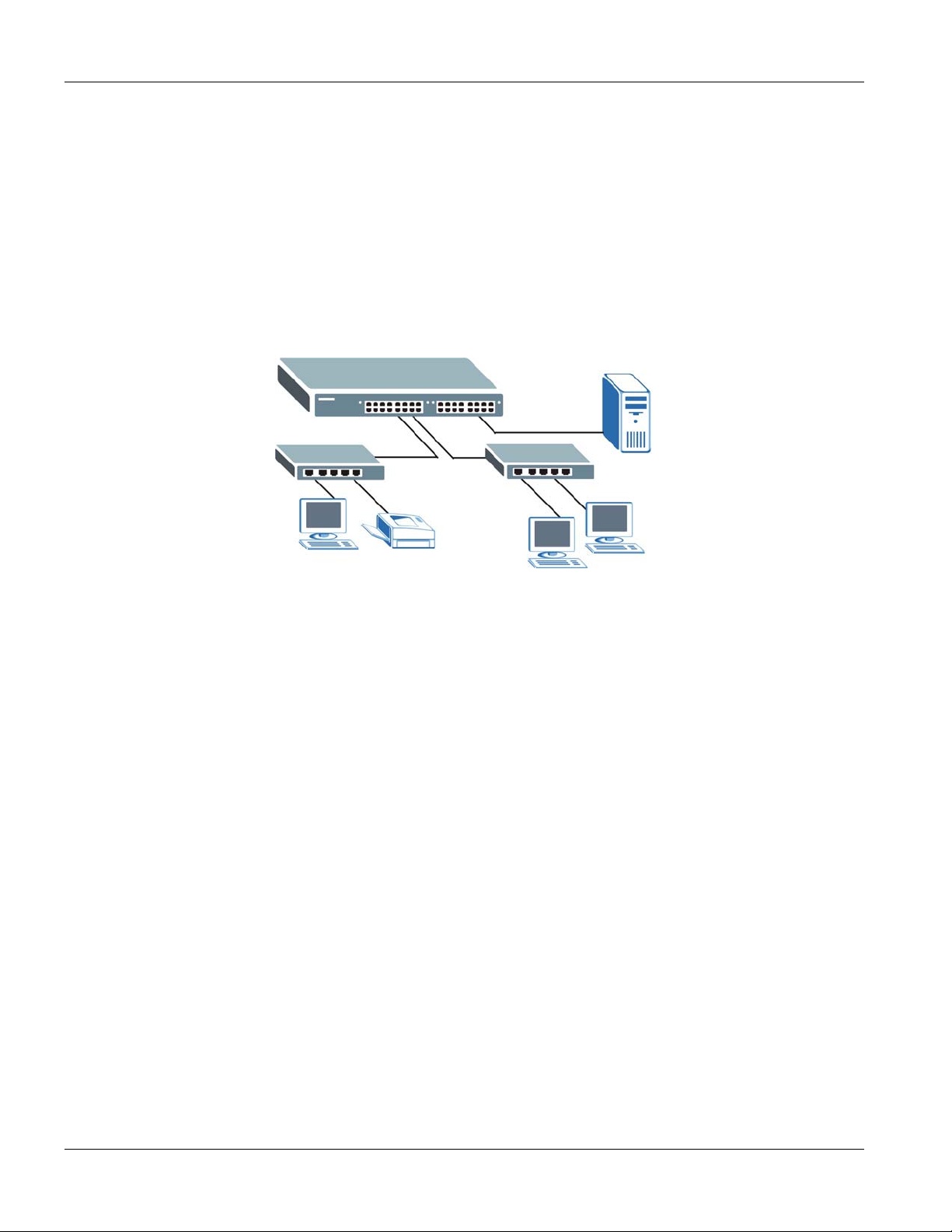
Dimension ES-4024 Ethernet Switch
1.2.1 Backbone Application
In this application, the switch is an ideal solution for small networks where rapid growth can be expected in the
near future.
The switch can be used standalone for a group of heavy traffic users. You can connect computers directly to the
switch’s port or connect other switches to the ES-4024.
In this example, all computers connected directly or indirectly to the ES-4024 can share super high-speed
applications on the server.
To expand the network, simply add more networking devices such as switches, routers, computers, print servers etc.
Figure 1-1 Backbone Application
1.2.2 Bridging Example
In this example application the switch is the ideal solution for different company departments to connect to the
corporate backbone. It can alleviate bandwidth contention and eliminate server and network bottlenecks. All users
that need high bandwidth can connect to high-speed department servers via the switch. You can provide a superfast uplink connection by using a GBIC module on the ES-4024.
Moreover, the switch eases supervision and maintenance by allowing network managers to centralize multiple
servers at a single location.
1-4 Getting to Know the ES-4024
Page 29
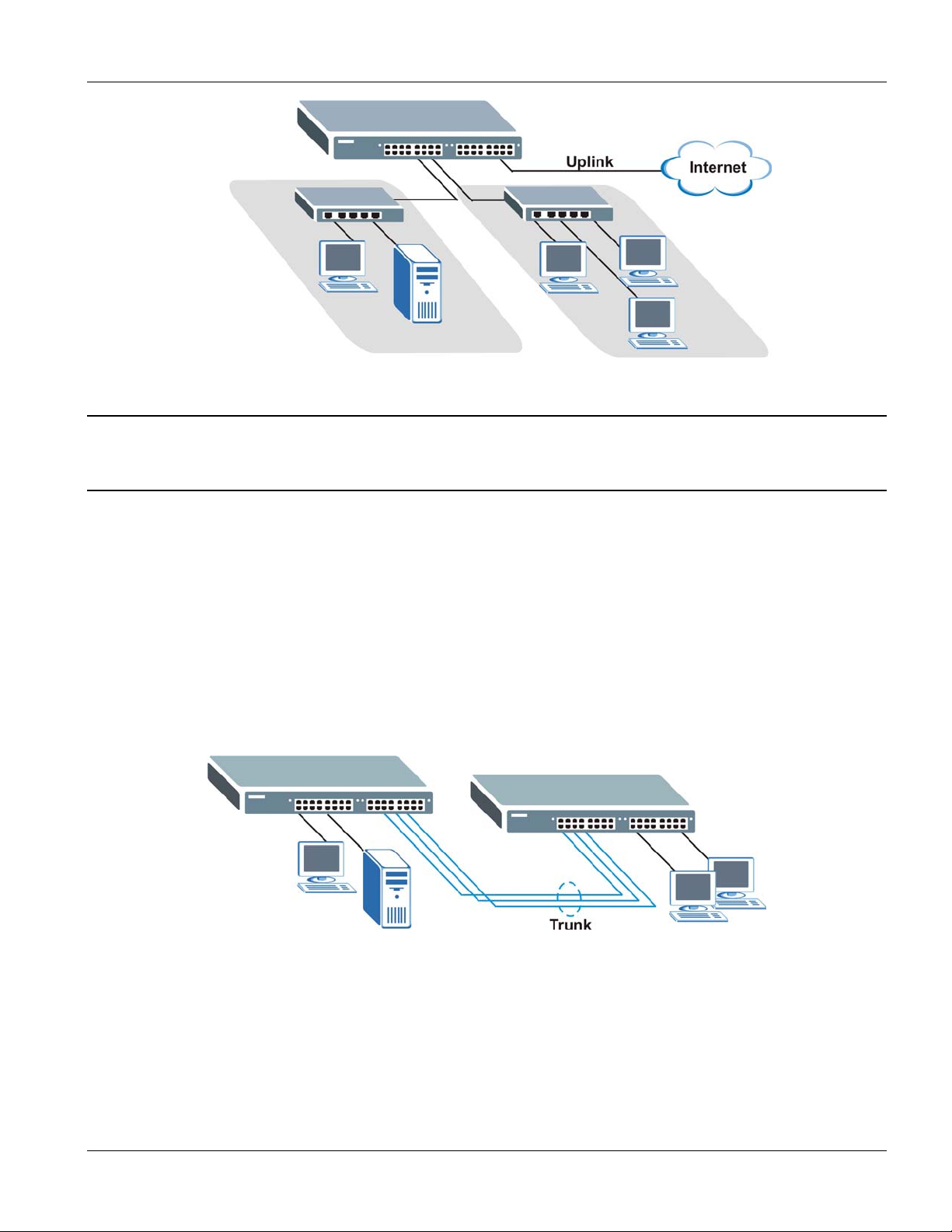
Dimension ES-4024 Ethernet Switch
Figure 1-2 Bridging Application
Full-duplex mode operation only applies to point-to-point access (for example, when attaching
the switch to a workstation, server, or another switch). When connecting to hubs, use a standard
cascaded connection set at half-duplex operation.
1.2.3 High Performance Switched Workgroup Example
The switch is ideal for connecting two power workgroups that need high bandwidth. In the following example, use
trunking to connect these two power workgroups.
Switching to higher-speed LANs such as FDDI or ATM is not feasible for most people due to the expense of
replacing all existing Ethernet cables and adapter cards, restructuring your network and complex maintenance.
The ES-4024 can provide the same bandwidth as FDDI and ATM at much lower cost while still being able to use
existing adapters and switches. Moreover, the current LAN structure can be retained as all ports can freely
communicate with each other.
Figure 1-3 High Performance Switched Workgroup Application
1.2.4 IEEE 802.1Q VLAN Application Examples
This section shows a workgroup and a shared server example using 802.1Q tagged VLANs. For more information
on VLANs, see the Switch Setup section and the VLAN chapter in this User’s Guide. A VLAN (Virtual Local Area
Network) allows a physical network to be partitioned into multiple logical networks. Stations on a logical network
Getting to Know the ES-4024 1-5
Page 30
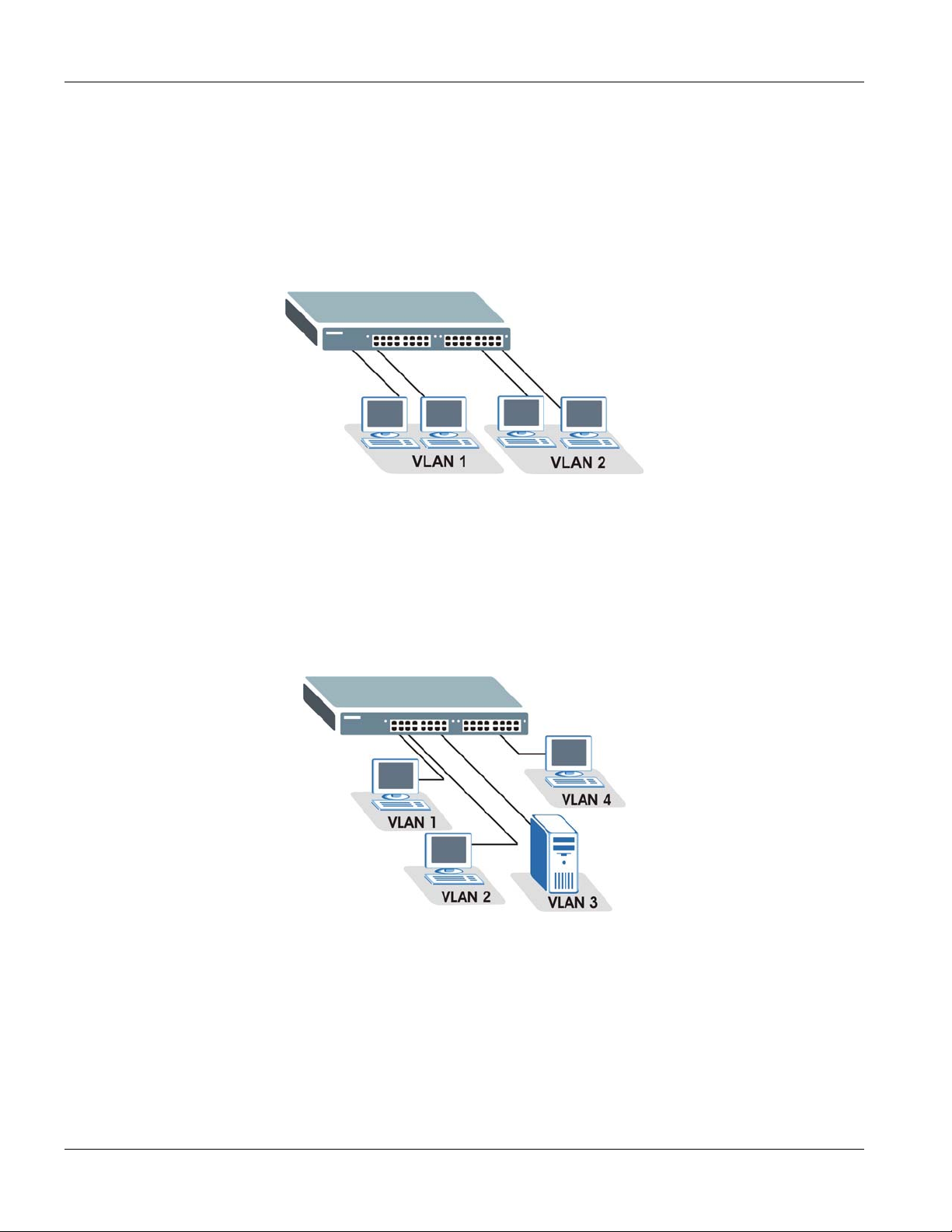
Dimension ES-4024 Ethernet Switch
belong to one group. A station can belong to more than one group. With VLAN, a station cannot directly talk to or
hear from stations that are not in the same group(s) unless such traffic first goes through a router.
Tag-based VLAN Workgroup Example
Ports in the same VLAN group share the same broadcast domain thus increase network performance through
reduced broadcast traffic. VLAN groups can be modified at any time by adding, moving or changing ports without
any re-cabling.
Figure 1-4 VLAN Workgroup Application
VLAN Shared Server Example
Shared resources such as a server can be used by all ports in the same VLAN as the server, as shown in the
following example. In this example, only ports that need access to the server need belong to VLAN 3 while they
can belong to other VLAN groups too.
Figure 1-5 Shared Server Using VLAN Example
1-6 Getting to Know the ES-4024
Page 31

Hardware Installation and Connections
Part II
Hardware Installation and Connections
This part acquaints you with installation scenarios of the ES, instructs you on how to make the
hardware connections including installing/removing modules, shows some stacking/uplink
examples and explains the front panel LEDs.
II
Page 32

Page 33

Dimension ES-4024 Ethernet Switch
Chapter 2
Hardware
This chapter shows two switch installation scenarios.
Installation
2.1 Installation Scenarios
The switch can be placed on a desktop or rack-mounted on a standard EIA rack. Use the rubber feet in a desktop
installation and the brackets in a rack-mounted installation.
For proper ventilation, allow at least 4 inches (10 cm) of clearance at the front and 3.4 inches (8
cm) at the back of the switch. This is especially important for enclosed rack installations.
2.1.1 Desktop Installation Procedure
Step 1. Make sure the switch is clean and dry.
Step 2. Set the switch on a smooth, level surface strong enough to support the weight of the switch and the
connected cables. Make sure there is a power outlet nearby.
Step 3. Make sure there is enough clearance around the switch to allow air circulation and the attachment of cables
and the power cord.
Step 4. Remove the adhesive backing from the rubber feet.
Step 5. Attach the rubber feet to each corner on the bottom of the switch. These rubber feet help protect the switch
from shock or vibration and ensure space between switches when stacking.
Figure 2-1 Attaching Rubber Feet
Do not block the ventilation holes. Leave space between switches when stacking.
Hardware Installation 2-1
Page 34

Dimension ES-4024 Ethernet Switch
2.1.2 Rack-Mounted Installation
The switch can be mounted on an EIA standard size, 19-inch rack or in a wiring closet with other equipment.
Follow the steps below to mount your switch on a standard EIA rack using a rack-mounting kit.
Step 1. Align one bracket with the holes on one side of the switch and secure it with the bracket screws smaller
than the rack-mounting screws. Similarly, attach the other bracket.
Figure 2-2 Attaching Mounting Brackets and Screws
Step 2. After attaching both mounting brackets, position the switch in the rack by lining up the holes in the
brackets with the appropriate holes on the rack. Secure the switch to the rack with the rack-mounting
screws.
Figure 2-3 Mounting the ES to an EIA standard 19-inch rack
2-2 Hardware Installation
Page 35

Dimension ES-4024 Ethernet Switch
Chapter 3
Hardware
This chapter acquaints you with the front and rear panels, shows you how to make the connections,
install/remove (optional) modules and explains the LEDs.
Connections
3.1 Safety Warnings
The length of exposed (bare) power wire should not exceed 7mm.
Do not use this product near water, for example, in a wet basement.
Only a qualified technician should service or disassemble this device.
3.2 Front Panel
The following figure shows the front panel of the ES-4024. The front panel contains a console port for local switch
management, switch LEDs, 24 RJ-45 Ethernet ports and two GBIC (3.3V) slots for uplink modules.
LEDs
The following table describes the front panel port connections.
CONNECTOR DESCRIPTION
Console Port The console port is for local configuration of the ES-4024.
24 10/100 Mbps RJ-45
Ethernet Ports
GBIC Slots For gigabit uplink modules.
Connect these ports to a computer, a hub, an Ethernet switch or router.
Ethernet Ports GBIC Slots Console Port
Figure 3-1 ES-4024 Front Panel
Table 3-1 ES-4024 Front Panel
3.2.1 Console Port
For local management, you can use a computer with terminal emulation software configured to the following
parameters:
VT100 terminal emulation 9600 bps
No parity, 8 data bits, 1 stop bit No flow control
Hardware Connections 3-1
Page 36

Dimension ES-4024 Ethernet Switch
Connect the male 9-pin end of the console cable to the console port of the ES-4024. Connect the female end to a
serial port (COM1, COM2 or other COM port) of your computer.
3.2.2 Ethernet Ports
The ES-4024 has 24 10/100Mbps auto-negotiating, auto-crossover Ethernet ports. In 10/100Mbps Fast Ethernet,
the speed can be 10Mbps or 100Mbps and the duplex mode can be half duplex or full duplex.
When auto-negotiation is turned on, an Ethernet port on the ES-4024 negotiates with the peer automatically to
determine the connection speed and duplex mode. If the peer Ethernet port does not support auto-negotiation or
turns off this feature, the ES-4024 determines the connection speed by detecting the signal on the cable and using
half duplex mode. When the ES-4024’s auto-negotiation is turned off, an Ethernet port uses the pre-configured
speed and duplex mode when making a connection, thus requiring you to make sure that the settings of the peer
Ethernet port are the same in order to connect.
Default Ethernet Settings
The factory default negotiation settings for the Ethernet ports on the ES-4024 are:
o Speed: Auto o Duplex: Auto
o Flow control: on
Auto-crossover
All ports are auto-crossover, that is auto-MDIX ports (Media Dependent Interface Crossover), so you may use
either a straight-through Ethernet cable or crossover Ethernet cable for all Ethernet port connections. Autocrossover ports automatically sense whether they need to function as crossover or straight ports, so crossover cables
can connect both computers and switches/hubs.
3.3 Stacking Module
LEDs in the (optional) stacking modules and module hardware installation steps are described in the corresponding
module manual.
3.4 Rear Panel
The following figure shows the rear panel of the ES-4024. The rear panel contains the slot for the stacking module
and the power receptacle. Refer to the module manual for descriptions on hardware installation.
Figure 3-2 ES-4024 Rear Panel: AC model
3-2 Hardware Connections
Page 37

Dimension ES-4024 Ethernet Switch
Figure 3-3 ES-4024 Rear Panel: DC Model
3.4.1 Power Connector
Make sure you are using the correct power source as shown on the panel.
To connect the power to the ES-4024 AC unit, insert the female end of power cord to the power receptacle on the
rear panel. Connect the other end of the supplied power cord to a 100~240VAC/1.5A power outlet. Make sure that
no objects obstruct the airflow of the fans (located on the side of the unit).
The ES-4024 DC unit requires DC power supply input of –48 VDC to -60 VDC, 1.84A Max. To connect the power
to the unit, insert the one end of the supplied power cord to the power receptacle on the rear panel and the other end
to a power outlet.
3.5 Front Panel LEDs
After you connect the power to the switch, view the LEDs to ensure proper functioning of the switch and as an aid
in troubleshooting. The front panel LEDs are as follows.
Figure 3-4 Front Panel LEDs
The following table describes the LED indicators on the front panel of the ES-4024.
Table 3-2 Front Panel: LED Descriptions
LED COLOR STATUS DESCRIPTION
S1
Green Blinking
The system is transmitting/receiving through the stacking port.
S2
PWR Green ON
ON
OFF
OFF
The link through the stacking port is up.
The link through the stacking port is down.
The system is turned on.
The system is off.
Hardware Connections 3-3
Page 38

Dimension ES-4024 Ethernet Switch
Table 3-2 Front Panel: LED Descriptions
LED COLOR STATUS DESCRIPTION
SYS Green Blinking
ON
OFF
ALM Red ON
OFF
LNK/ACT
(Ethernet ports)
Amber Blinking
FDX/COL
(Ethernet ports)
ACT
Green Blinking
ON
OFF
ON
OFF
Amber
Green On The port has a successful connection.
Blinking The Ethernet port is negotiating in half-duplex mode and collisions are
ON The Ethernet port is negotiating in full-duplex mode.
OFF The Ethernet port is negotiating in half-duplex mode and no collisions are
The system is rebooting and performing self-diagnostic tests.
The system is on and functioning properly.
The power is off or the system is not ready/malfunctioning.
There is a hardware failure.
The system is functioning normally.
The system is transmitting/receiving to/from a 10 Mbps Ethernet network.
The link to a 10 Mbps Ethernet network is up.
The link to a 10 Mbps Ethernet network is down.
The system is transmitting/receiving to/from a 100 Mbps Ethernet network.
The link to a 100 Mbps Ethernet network is up.
The link to a 100 Mbps Ethernet network is down.
occurring; the more collisions that occur the faster the LED blinks.
occurring.
(GBIC Slots)
Off No Ethernet device is connected to this port.
ACT
(GBIC Slots)
Off The port is not sending or receiving data.
Green Blinking The port is sending or receiving data.
3.6 Stacking Scenario Examples
Use Ethernet cables when stacking the switches. See the following figures for example stacking scenarios using the
stacking module. The switches must form a closed ring in all scenarios.
3-4 Hardware Connections
Page 39

Figure 3-5 Stacking Example 1
Dimension ES-4024 Ethernet Switch
Figure 3-6 Stacking Example 2
Hardware Connections 3-5
Page 40

Dimension ES-4024 Ethernet Switch
Figure 3-7 Stacking Example 3
See the chapter on CLI commands for information on configuring the stacking modules (as well as other ports)
using line commands.
3.7 Uplink Scenario Example
Use Ethernet cables when daisy-chaining/uplinking the switches. See the following figure for an example uplink
connection using the stacking module. You must uplink to a Gigabit switch using a cat. 5 Ethernet cable supporting
gigabit line rate when uplinking using the stacking module. Uplink scenarios using an uplink module depend on the
uplink module you use.
3-6 Hardware Connections
Page 41

Dimension ES-4024 Ethernet Switch
Figure 3-8 Uplink Example
3.8 Accessing the ES-4024
You may use the embedded web configurator or command line interface to configure the ES-4024. If you’re using
the web configurator, you need Internet Explorer 5.5 and later or Netscape Navigator 6 and later.
You can access the command line interface using a terminal emulation program on a computer connected to the
switch console port (see Section 3.2.1) or access the switch via an Ethernet port using Telnet.
You can use the “config save” command to save 802.1Q, STP, Cluster and IP configuration
changes to non-volatile memory (Flash). These changes are effective after you restart the switch.
However you cannot use “config save” for all other line command configurations. These are
saved in volatile memory (DRAM), so are not effective after you restart the switch.
The next part of this guide discusses configuring the ES-4024 using the web configurator.
Hardware Connections 3-7
Page 42

Page 43

Getting Started
Part III
Getting Started
This part introduces you to the ES-4024 web configurator, describes the Status and Port
Details screens and shows you how to configure the Basic Setting screens.
III
Page 44

Page 45

Dimension ES-4024 Ethernet Switch
Chapter 4
Introducing
This section introduces the configuration and functions of the Web Configurator.
4.1 Introduction
The embedded web configurator allows you to manage the switch from anywhere through a standard browser
such as Microsoft Internet Explorer or Netscape Navigator.
Use Internet Explorer 5.5 and later or Netscape Navigator 6 and later versions.
4.2 System Login
Step 1. Start Internet Explorer or Netscape Navigator web browser.
Step 2.
Step 3. The login screen appears. The default username is admin and associated default password is 1234. The
Type “http://” and the IP address of the switch (for example, the default is 192.168.1.1) in the Location or
Address field. Press Enter.
date and time display as shown if you have not configured a time server nor manually entered a time and
date in the General Setup screen.
the Web Configurator
Figure 4-1 Web Configurator: login
Step 4. Click OK to view the first web configurator screen.
4.3 The Status Screen
The Status screen is the first screen that displays when you access the web configurator.
The following figure shows the navigating components of a web configurator screen.
Introducing the Web Configurator
4-1
Page 46

Dimension ES-4024 Ethernet Switch
Click Status to view
Navigation Panel.
Click on a tab to
display related links.
current device statistics.
Figure 4-2 Web Configurator Home Screen (Status)
Click here for help on
configuring a screen.
Click Logout to exit the
web configurator.
In the navigation panel, click a main link to reveal a list of submenu links.
4-2 Introducing the Web Configurator
Page 47

Dimension ES-4024 Ethernet Switch
Table 4-1 Navigation Panel Sub-links Overview
BASIC SETTING ADVANCED APPLICATION ROUTING PROTOCOL MANAGEMENT
The following table lists the various web configurator screens within the sub-links.
Table 4-2 Web Configurator Screen Sub-links Details
BASIC SETTING ADVANCED APPLICATIONS ROUTING PROTOCOL MANAGEMENT
System Info
General Setup
Switch Setup
IP Setup
Port Setup
VLAN
VLAN Status
VLAN Port Setting
Static VLAN
Static MAC Forwarding
Filtering
Static Routing
RIP
IGMP
DVMRP
OSPF Status
OSPF Configuration
Maintenance
Firmware Upgrade
Restore Configuration
Backup Configuration
Load Factory Default
Reboot System
Spanning Tree Protocol Status
Spanning Tree Protocol
Configuration
Bandwidth Control
Broadcast Storm Control
Mirroring
Link Aggregation
Link Aggregation Protocol
Status
Link Aggregation
Port Authentication
OSPF Interface
OSPF Virtual Link
Diagnostic
Cluster Management Status
Cluster Management
Configuration
Filtering Database
IP Table
ARP Table
Routing Table
DHCP Server Status
Introducing the Web Configurator 4-3
Page 48

Dimension ES-4024 Ethernet Switch
Table 4-2 Web Configurator Screen Sub-links Details
BASIC SETTING ADVANCED APPLICATIONS ROUTING PROTOCOL MANAGEMENT
RADIUS
802.1x
Port Security
DHCP
Access Control
SNMP
Logins
Service Access Control
Remote Management
DiffServ
DSCP Setting
Marking Rule Setting
Queuing Method
VRRP Status
VRRP Configuration
The following table describes the links in the navigation panel.
Table 4-3 Navigation Panel Links
LABEL DESCRIPTION
Basic Settings
System Info This link takes you to a screen that displays general system and hardware monitoring
General Setup This link takes you to a screen where you can configure general identification information
Switch Setup This link takes you to a screen where you can set up global switch parameters such as
IP Setup This link takes you to a screen where you can configure the IP address, subnet mask
Port Setup This link takes you to screens where you can configure settings for individual switch ports.
Advanced Application
VLAN This link takes you to screens where you can configure port-based or 802.1Q VLAN
Static MAC
Forwarding
Filtering This link takes you to a screen to set up filtering rules.
Spanning Tree
Protocol
information.
about the switch.
VLAN type, MAC address learning, IGMP snooping, GARP and priority queues.
(necessary for switch management) and DNS (domain name server) and set up to 64 IP
routing domains.
(depending on what you configured in the Switch Setup menu).
This link takes you to screens where you can configure static MAC addresses for a port.
These static MAC addresses do not age out.
This link takes you to screens where you can configure the STP/RSTP to prevent network
loops.
4-4
Introducing the Web Configurator
Page 49

Dimension ES-4024 Ethernet Switch
Table 4-3 Navigation Panel Links
LABEL DESCRIPTION
Bandwidth Control This link takes you to screens where you can cap the maximum bandwidth allowed from
specified source(s) to specified destination(s).
Broadcast Storm
Control
Mirroring This link takes you to screens where you can copy traffic from one port or ports to another
Link Aggregation This link takes you to a screen where you can logically aggregate physical links to form
Port Authentication This link takes you to a screen where you can configure RADIUS (Remote Authentication
Port Security This link takes you to a screen where you can activate MAC address learning and set the
DHCP This link takes you to a screen where you can configure the DHCP settings for the
Access Control This link takes you to screens where you can change the system login password and
DiffServ This link takes you to screens where you can enable DiffServ, configure marking rules
Queuing Method This link takes you to a screen where you can configure SPQ or WFQ with associated
VRRP This link takes you to screens where you can configure redundant virtual router for your
This link takes you to a screen to set up broadcast filters.
port in order that you can examine the traffic from the first port without interference
one logical, higher-bandwidth link.
Dial-In User Service), a protocol for user authentication that allows you to use an external
server to validate an unlimited number of users.
maximum number of MAC addresses to learn on a port.
network on the ES-4024.
configure SNMP and remote management.
and set DSCP-to-IEEE802.1p mappings.
queue weights for each port.
network.
Routing Protocol
Static Route This link takes you to screens where you can configure static routes. A static route
defines how the ES-4024 should forward traffic by configuring the TCP/IP parameters
manually.
RIP This link takes you to a screen where you can configure the RIP (Routing Information
Protocol) direction and versions.
IGMP This link takes you to a screen where you can configure the IGMP settings.
DVMRP This link takes you to a screen where you can configure the DVMRP (Distance Vector
Multicast Routing Protocol) settings.
OSPF This link takes you to screens where you can view the OSPF status and configure OSPF
settings.
Advanced Management
Maintenance This link takes you to screens where you can perform firmware and configuration file
maintenance as well as reboot the system.
Diagnostic This link takes you to screens where you can view system logs and test port(s).
Cluster Management This link takes you to a screen where you can configure clustering management and view
its status.
MAC Table This link takes you to a screen where you can view the MAC addresses (and types) of
devices attached to what ports and VLAN IDs.
Introducing the Web Configurator 4-5
Page 50

Dimension ES-4024 Ethernet Switch
Table 4-3 Navigation Panel Links
LABEL DESCRIPTION
IP Table This link takes you to a screen where you can view the IP addresses (and types) of
devices attached to what ports and VLAN IDs.
ARP Table This link takes you to a screen where you can view the MAC addresses – IP address
resolution table.
Routing Table This link takes you to a screen where you can view the routing table in the ES.
DHCP Server Status This link takes you to screens where you can view the general and detail DHCP server
status.
4.3.1 Change Your Password
After you log in for the first time, it is recommended you change the default administrator password. Click
Advanced Application, Access Control and then Logins to display the next screen.
Figure 4-3 Change Administrator Login Password
4.4 Switch Lockout
You are locked out from managing the switch if another administrator is currently logged in. You must wait until
he/she has logged out before you can log in.
Moreover, you could lock yourself (and all others) out from the switch by:
1. Deleting the management VLAN (default is VLAN 1).
2. Deleting all IP routing domains.
4-6
Introducing the Web Configurator
Page 51

Dimension ES-4024 Ethernet Switch
3. Deleting all port-based VLANs with the CPU port as a member. The “CPU port” is the management port of
the switch.
4. Filtering all traffic to the CPU port.
5. Disabling all ports.
6. Assigning minimum bandwidth to the CPU port. If you limit bandwidth to the CPU port, you may find that
the switch performs sluggishly or not at all.
Be careful not to lock yourself and others out of the switch.
4.5 Resetting the Switch
If you lock yourself (and others) from the switch or forget the ES-4024 password, you will need to reload the
factory-default configuration file.
Uploading the factory-default configuration file replaces the current configuration file with the factory-default
configuration file. This means that you will lose all previous configurations and the speed of the console port will
be reset to the default of 9600bps with 8 data bit, no parity, one stop bit and flow control set to none. The
password will also be reset to “1234” and the IP address to 192.168.1.1.
To upload the configuration file, do the following:
Step 1. Connect to the console port using a computer with terminal emulation software. See the chapter on
hardware connections for details.
Step 2. Disconnect and reconnect the switch’s power to begin a session. When you reconnect the switch’s power,
you will see the initial screen.
Step 3. When you see the message “Press any key to enter Debug Mode within 3 seconds”
press any key to enter debug mode.
Step 4. Type atlc after the “Enter Debug Mode” message.
Step 5. Wait for the “Starting XMODEM upload” message before activating XMODEM upload on your
terminal.
Step 6. After a configuration file upload, type atgo to restart the switch.
Introducing the Web Configurator 4-7
Page 52

Dimension ES-4024 Ethernet Switch
Bootbase Version: V1.0 | 04/25/2003 10:01:06
RAM: Size = 32768 Kbytes
FLASH: Intel 32M
ZyNOS Version: V3.50(DU.0)b6 | 07/11/2003 18:00:29
Press any key to enter debug mode within 3 seconds.
....................
Enter Debug Mode
ES-4024> atlc
Starting XMODEM upload (CRC mode)....
CCCCCCCCCCCCCCCC
Total 262144 bytes received.
Erasing..
................................................................
OK
ES-4024> atgo
Figure 4-4 Resetting the Switch: Via Console Port
The switch is now reinitialized with a default configuration file including the default password of “1234”.
4.5.1 Logging Out of the Web Configurator
Click Logout in a screen to exit the web configurator. You have to log in with your password again after you log
out. This is recommended after you finish a management session both for security reasons and so as you don’t
lock out other switch administrators.
Figure 4-5 Web Configurator: Logout Screen
4.5.2 Help
The web configurator’s online help has descriptions of individual screens and some supplementary information.
Click the Help link from a web configurator screen to view an online help description of that screen.
4-8 Introducing the Web Configurator
Page 53

Dimension ES-4024 Ethernet Switch
Chapter 5
System
This chapter describes the system status (web configurator home page) and port details screens.
5.1 About System Statistics and Information
The home screen of the web configurator displays a port statistical summary with links to each port showing
statistical details.
5.2 Port Status Summary
To view the port statistics, click Status in all web configurator screens to display the Status screen as shown next.
Status and Port Statistics
Figure 5-1 Status
The following table describes the labels in this screen.
System Status and Port Statistics
5-1
Page 54

Dimension ES-4024 Ethernet Switch
Table 5-1 Status
LABEL DESCRIPTION
System up Time This field shows how long the system has been running since the last time it was started.
Port This identifies the Ethernet port. Click a port number to display the Port Details screen (refer to
Section 5.2.1).
Link This field displays the speed (either 10M for 10Mbps, 100M for 100Mbps or another value
depending on the uplink module being used) and the duplex (F for full duplex or H for half).
State This field displays the STP (Spanning Tree Protocol) state of the port. See the chapter on STP
for details on STP states.
LACP This fields displays whether LACP (Link Aggregation Control Protocol) has been enabled on the
port.
TxPkts This field shows the number of transmitted frames on this port.
RxPkts This field shows the number of received frames on this port.
Errors This field shows the number of received errors on this port.
Tx KB/s This field shows the number of kilobytes per second transmitted on this port.
Rx KB/s This field shows the number of kilobytes per second received on this port.
Up Time This field shows the total amount of time in hours, minutes and seconds the port has been up.
Poll Interval(s) The text box displays how often (in seconds) this screen refreshes. You may change the refresh
interval by typing a new number in the text box and then clicking Set Interval.
Stop Click Stop to halt system statistic polling.
Clear Counter Select a port from the Port drop-down list box and then click Clear Counter to erase the
recorded statistical information for that port.
5.2.1 Port Details
Click a number in the Port column in the Status screen to display individual port statistics. Use this screen to
check status and detailed performance data about an individual port on the switch.
5-2 System Status and Port Statistics
Page 55

Dimension ES-4024 Ethernet Switch
Figure 5-2 Status: Port Details
The following table describes the labels in this screen.
Table 5-2 Status: Port Details
LABEL DESCRIPTION
Port Info
Link This field shows whether the Ethernet connection is down, and the speed/duplex mode.
System Status and Port Statistics 5-3
Page 56

Dimension ES-4024 Ethernet Switch
Table 5-2 Status: Port Details
LABEL DESCRIPTION
Status This field shows the training state of the ports. The states are FORWARDING (forwarding),
which means the link is functioning normally or STOP (the port is stopped to break a loop or
duplicate path).
LACP This field shows if LACP is enabled on this port or not.
TxPkts This field shows the number of transmitted frames on this port
RxPkts This field shows the number of received frames on this port
Errors This field shows the number of received errors on this port.
Tx KB/s This field shows the number kilobytes per second transmitted on this port.
Rx KB/s This field shows the number of kilobytes per second received on this port.
Up Time This field shows the total amount of time the connection has been up.
Tx Packet
The following fields display detailed information about packets transmitted.
TX This field shows the number of good packets (unicast, multicast and broadcast) transmitted.
Multicast This field shows the number of good multicast packets transmitted.
Broadcast This field shows the number of good broadcast packets transmitted.
Pause This field shows the number of 802.3x Pause packets transmitted.
Tagged This field shows the number of packets with VLAN tags transmitted.
Rx Packet
The following fields display detailed information about packets received.
RX This field shows the number of good packets (unicast, multicast and broadcast) received.
64 This field shows the number of packets (including bad packets) received that were 64 octets in
length.
65-127 This field shows the number of packets (including bad packets) received that were between 65
and 127 octets in length.
128-255 This field shows the number of packets (including bad packets) received that were between 128
and 255 octets in length.
5-4
256-511 This field shows the number of packets (including bad packets) received that were between 256
and 511 octets in length.
512-1023 This field shows the number of packets (including bad packets) received that were between 512
and 1023 octets in length.
1024-1518 This field shows the number of packets (including bad packets) received that were between
1024 and 1518 octets in length.
System Status and Port Statistics
Page 57

Dimension ES-4024 Ethernet Switch
Table 5-2 Status: Port Details
LABEL DESCRIPTION
>1518 This field shows the number of packets (including bad packets) transmitted that were greater
than 1518 octets in length.
Multicast This field shows the number of good multicast packets received.
Broadcast This field shows the number of good broadcast packets received.
Pause This field shows the number of 802.3x Pause packets received.
Tagged This field shows the number of packets with VLAN tags received.
Control This field shows the number of control packets received (including those with CRC error) but it
does not include the 802.3x Pause packets.
TX Collision
The following fields display information on collisions while transmitting.
Single This is a count of successfully transmitted packets for which transmission is inhibited by exactly
one collision.
Multiple This is a count of successfully transmitted packets for which transmission was inhibited by more
than one collision.
Excessive This is a count of packets for which transmission failed due to excessive collisions. Excessive
collision is defined as the number of maximum collisions before the retransmission count is
reset.
Late This is the number of times a late collision is detected, that is, after 512 bits of the packets have
already been transmitted.
Error Packet The following fields display detailed information about packets received that were in error.
RX CRC This field shows the number of packets received with CRC (Cyclic Redundant Check) error(s).
Length This field shows the number of packets received with a length that was out of range.
Alignment This field shows the number of packets received of proper size but with CRC error(s) and a non-
integral number of octets.
Runt This field shows the number of packets received that were too short (shorter than 64 octets),
including the ones with CRC errors.
Dropped Packet The following filed indicates why packets were dropped.
Giant This field shows the number of packets dropped because they were bigger than the maximum
frame size.
Poll Interval(s) The text box displays how often (in seconds) this screen refreshes. You may change the refresh
interval by typing a new number in the text box and then clicking Set Interval.
Stop Click Stop to stop port statistic polling.
System Status and Port Statistics 5-5
Page 58

Page 59

Dimension ES-4024 Ethernet Switch
Chapter 6
Basic
This chapter describes how to configure the System Info, General Setup, Switch Setup, IP Setup
and Port Setup screens.
6.1 Introducing The Basic Setting Screens
The System Info screen displays general switch information (such as firmware version number) and hardware
polling information (such as fan speeds). The General Setup screen allows you to configure general switch
identification information. The General Setup screen also allows you to set the system time manually or get the
current time and date from an external server when you turn on your switch. The real time is then displayed in the
switch logs. The Switch Setup screen allows you to set up and configure global switch features. The IP Setup
screen allows you to configure a switch IP address in each routing domain, subnet mask(s) and DNS (domain
name server) for management purposes.
6.2 System Information
Setting
In the navigation panel, click Basic Setting and System Info to display the screen as shown. You can check the
firmware version number and monitor the switch temperature, fan speeds and voltage in this screen.
Basic Setting
Figure 6-1 Basic Setting: System Info
6-1
Page 60

Dimension ES-4024 Ethernet Switch
The following table describes the labels in this screen.
Table 6-1 Basic Setting: System Info
LABEL DESCRIPTION
System Name This field displays the switch 's model name.
ZyNOS F/W Version This field displays the version number of the switch 's current firmware including the date
created.
Ethernet Address This field refers to the Ethernet MAC (Media Access Control) address of the switch.
Hardware Monitor
Temperature Unit The switch has temperature sensors that are capable of detecting and reporting if the
temperature rises above the threshold. You may choose the temperature unit (Centigrade
or Fahrenheit) in this field.
Temperature MAC, CPU and PHY refer to the location of the temperature sensors on the switch printed
circuit board.
Current This shows the current temperature in degrees centigrade at this sensor.
MAX This field displays the maximum temperature measured at this sensor.
MIN This field displays the minimum temperature measured at this sensor.
Threshold This field displays the upper temperature limit at this sensor.
Status This field displays Normal for temperatures below the threshold and Error for those above.
Fan Speed (RPM) A properly functioning fan is an essential component (along with a sufficiently ventilated,
cool operating environment) in order for the device to stay within the temperature
threshold. Each fan has a sensor that is capable of detecting and reporting if the fan speed
falls below the threshold shown.
Current This field displays this fan's current speed in Revolutions Per Minute (RPM).
MAX This field displays this fan's maximum speed measured in Revolutions Per Minute (RPM).
MIN This field displays this fan's minimum speed measured in Revolutions Per Minute (RPM).
"<41" is displayed for speeds too small to measure (under 2000 RPM).
Threshold This field displays the minimum speed at which a normal fan should work.
Status Normal indicates that this fan is functioning above the minimum speed. Error indicates
that this fan is functioning below the minimum speed.
Voltage(V) The power supply for each voltage has a sensor that is capable of detecting and reporting
if the voltage falls out of the tolerance range.
Current This is the current voltage reading.
MAX This field displays the maximum voltage measured at this point.
MIN This field displays the minimum voltage measured at this point.
6-2 Basic Setting
Page 61
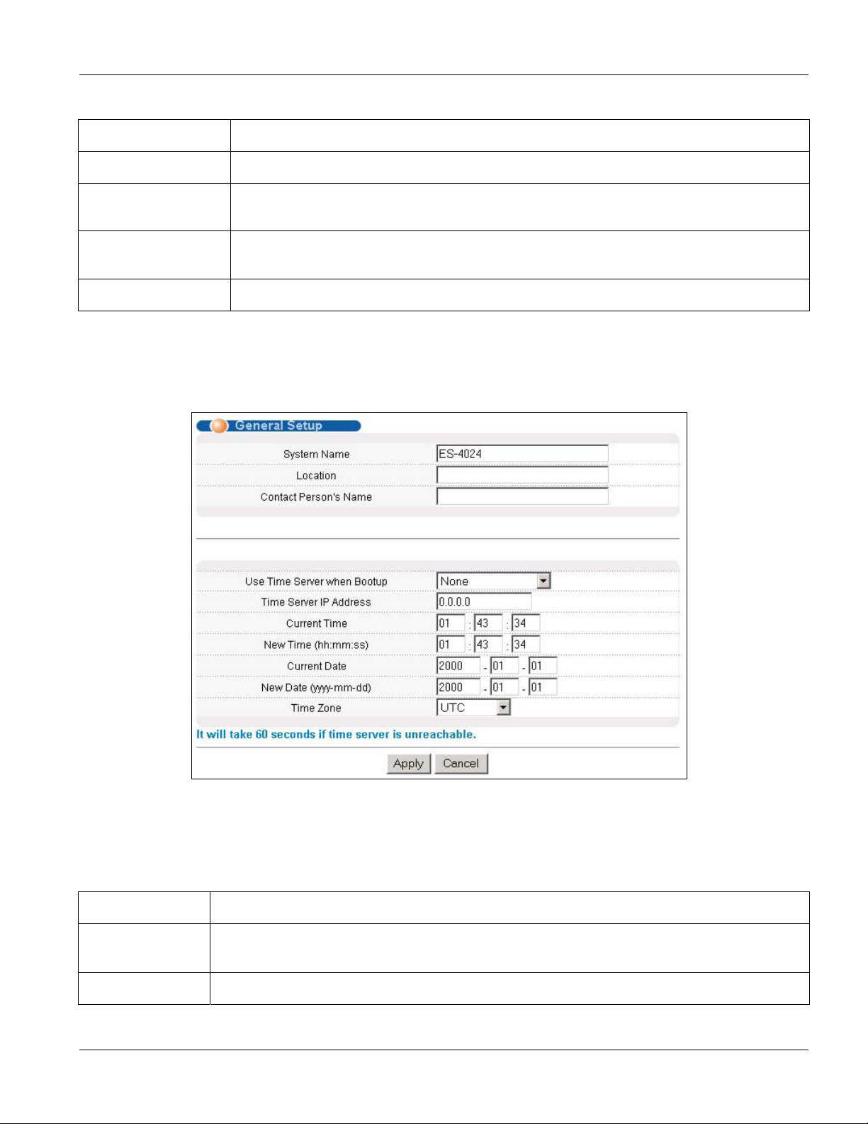
Dimension ES-4024 Ethernet Switch
Table 6-1 Basic Setting: System Info
LABEL DESCRIPTION
Threshold This field displays the minimum voltage at which the switch should work.
Status Normal indicates that the voltage is within an acceptable operating range at this point;
otherwise Error is displayed.
Poll Interval(s) The text box displays how often (in seconds) this screen refreshes. You may change the
refresh interval by typing a new number in the text box and then clicking Set Interval.
Stop Click Stop to halt statistic polling.
6.3 General Setup
Click Basic Setting and General Setup in the navigation panel to display the screen as shown.
Figure 6-2 Basic Setting: General Setup
The following table describes the labels in this screen.
Table 6-2 Basic Setting: General Setup
LABEL DESCRIPTION
System Name Choose a descriptive name for identification purposes. This name consists of up to 32
printable characters; spaces are not allowed.
Location Enter the geographic location (up to 30 characters) of your switch.
Basic Setting 6-3
Page 62

Dimension ES-4024 Ethernet Switch
Table 6-2 Basic Setting: General Setup
LABEL DESCRIPTION
Contact Person's
Name
Use Time Server
when Bootup
Time Server IP
Address
Current Time This field displays the time you open this menu (or refresh the menu).
New Time
(hh:min:ss)
Current Date This field displays the date you open this menu.
Enter the name (up to 30 characters) of the person in charge of this switch.
Enter the time service protocol that a timeserver sends when you turn on the switch. Not all
timeservers support all protocols, so you may have to use trial and error to find a protocol that
works. The main differences between them are the time format.
Daytime (RFC 867) format is day/month/year/time zone of the server.
Time (RFC-868) format displays a 4-byte integer giving the total number of seconds since
1970/1/1 at 0:0:0.
NTP (RFC-1305) is similar to Time (RFC-868).
None is the default value. Enter the time manually. Each time you turn on the switch, the time
and date will be reset to 2000-1-1 0:0.
Enter the IP address (or URL if you configure a domain name server in the IP Setup screen)
of your timeserver. The switch searches for the timeserver for up to 60 seconds. If you select a
timeserver that is unreachable, then this screen will appear locked for 60 seconds. Please
wait.
Enter the new time in hour, minute and second format. The new time then appears in the
Current Time field after you click Apply.
New Date (yyyymm-dd)
Time Zone Select the time difference between UTC (Universal Time Coordinated, formerly known as
Apply Click Apply to save the settings.
Cancel Click Cancel to reset the fields to your previous configuration.
Enter the new date in year, month and day format. The new date then appears in the Current
Date field after you click Apply.
GMT, Greenwich Mean Time) and your time zone from the drop-down list box.
6.4 Introduction to VLANs
A VLAN (Virtual Local Area Network) allows a physical network to be partitioned into multiple logical
networks. Devices on a logical network belong to one group. A device can belong to more than one group. With
VLAN, a device cannot directly talk to or hear from devices that are not in the same group(s); the traffic must first
go through a router.
In MTU (Multi-Tenant Unit) applications, VLAN is vital in providing isolation and security among the
subscribers. When properly configured, VLAN prevents one subscriber from accessing the network resources of
another on the same LAN, thus a user will not see the printers and hard disks of another user in the same building.
VLAN also increases network performance by limiting broadcasts to a smaller and more manageable logical
broadcast domain. In traditional switched environments, all broadcast packets go to each and every individual
port. With VLAN, all broadcasts are confined to a specific broadcast domain.
6-4
Basic Setting
Page 63
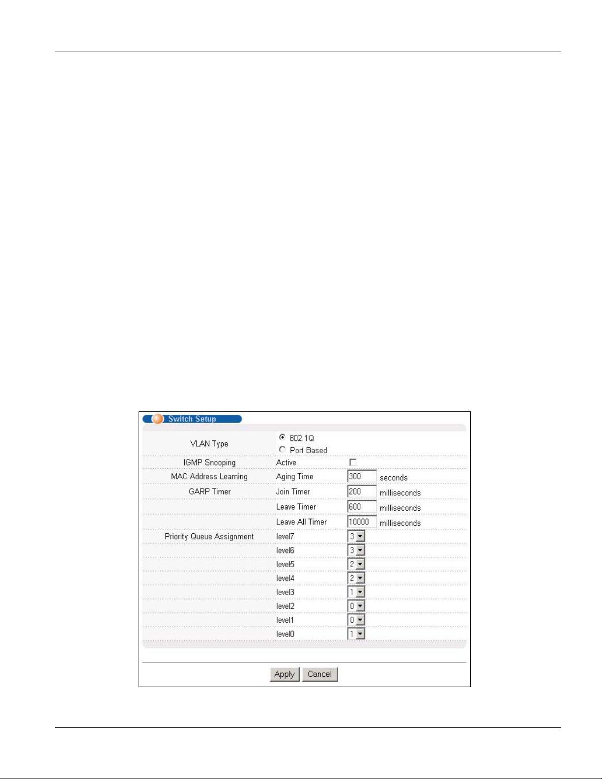
Dimension ES-4024 Ethernet Switch
Note that VLAN is unidirectional; it only governs outgoing traffic.
See the VLAN chapter for information on port-based and 802.1Q tagged VLANs.
6.5 IGMP Snooping
IGMP (Internet Group Multicast Protocol) is a network-layer protocol used to establish membership in a Multicast
group - it is not used to carry user data. Refer to RFC 2236 for information IGMP version 2 and RFC 1112 for
IGMP version 1.
A layer-2 switch can passively snoop on IGMP Query, Report and Leave (IGMP version 2) packets transferred
between IP multicast routers/switches and IP multicast hosts to learn the IP multicast group membership. It checks
IGMP packets passing through it, picks out the group registration information, and configures multicasting
accordingly.
Without IGMP snooping, multicast traffic is treated in the same manner as broadcast traffic, that is, it is forwarded
to all ports. With IGMP snooping, group multicast traffic is only forwarded to ports that are members of that
group. IGMP Snooping generates no additional network traffic, allowing you to significantly reduce multicast
traffic passing through your switch.
6.6 Switch Setup Screen
Click Basic Setting and then Switch Setup in the navigation panel to display the screen as shown. The VLAN
setup screens change depending on whether you choose 802.1Q or Port Based in the VLAN Type field in this
screen. Refer to the chapter on VLAN.
Figure 6-3 Basic Setting: Switch Setup
Basic Setting 6-5
Page 64

Dimension ES-4024 Ethernet Switch
The following table describes the labels in this screen.
Table 6-3 Basic Setting: Switch Setup
LABEL DESCRIPTION EXAMPLE
VLAN Type Choose 802.1Q or Port Based. The VLAN Setup screen changes depending on
whether you choose 802.1Q VLAN type or Port Based VLAN type in this screen.
IGMP
Snooping
See Section 6.4 and the chapter on VLAN for more information.
Select the Active checkbox to enable IGMP snooping have group multicast traffic
only forwarded to ports that are members significantly reducing multicast traffic
passing through your switch. See Section 6.5 for more information on IGMP
snooping.
802.1Q
You cannot enable both IGMP snooping and IGMP at the same time.
Refer to the section on IGMP for more information.
MAC Address
Learning
Aging Time Enter a time from 10 to 3000 seconds. This is how long all dynamically learned
GARP Timer: Switches join VLANs by making a declaration. A declaration is made by issuing a Join message
using GARP. Declarations are withdrawn by issuing a Leave message. A Leave All message terminates all
registrations. GARP timers set declaration timeout values. See the chapter on VLAN setup for more background
information.
Join Timer Join Timer sets the duration of the Join Period timer for GVRP in milliseconds.
MAC address learning reduces outgoing traffic broadcasts. For MAC address
learning to occur on a port, the port must be active.
MAC addresses remain in the MAC address table before they age out (and must
be relearned).
Each port has a Join Period timer. The allowed Join Time range is between 100
and 65535 milliseconds; the default is 200 milliseconds. See the chapter on
VLAN setup for more background information.
300
200 milliseconds
(default)
Leave Timer Leave Timer sets the duration of the Leave Period timer for GVRP in
milliseconds. Each port has a single Leave Period timer. Leave Time must be two
times larger than Join Timer; the default is 600 milliseconds.
Leave All
Timer
Priority Queue Assignment
IEEE 802.1p defines up to 8 separate traffic types by inserting a tag into a MAC-layer frame that contains bits to
define class of service. Frames without an explicit priority tag are given the default priority of the ingress port. Use
the next two fields to configure the priority level-to-physical queue mapping.
The switch has 4 physical queues that you can map to the 8 priority levels. On the switch, traffic assigned to higher
index queues gets through faster while traffic in lower index queues is dropped if the network is congested.
Priority Level (The following descriptions are based on the traffic types defined in the IEEE 802.1d standard (which
incorporates the 802.1p).
Level 7 Typically used for network control traffic such as router configuration messages.
Level 6 Typically used for voice traffic that is especially sensitive to jitter (jitter is the variations in delay).
Leave All Timer sets the duration of the Leave All Period timer for GVRP in
milliseconds. Each port has a single Leave All Period timer. Leave All Timer must
be larger than Leave Timer; the default is 1000 milliseconds.
600 milliseconds
(default)
1000
milliseconds
(default)
6-6 Basic Setting
Page 65

Dimension ES-4024 Ethernet Switch
Table 6-3 Basic Setting: Switch Setup
LABEL DESCRIPTION EXAMPLE
Level 5 Typically used for video that consumes high bandwidth and is sensitive to jitter.
Level 4
Level 3
Level 2 This is for “spare bandwidth”.
Level 1
Level 0 Typically used for best-effort traffic.
Apply Click Apply to save the settings.
Cancel Click Cancel to reset the fields to your previous configuration.
Typically used for controlled load, latency-sensitive traffic such as SNA (Systems Network
Architecture) transactions.
Typically used for “excellent effort” or better than best effort and would include important business
traffic that can tolerate some delay.
This is typically used for non-critical “background” traffic such as bulk transfers that are allowed but
that should not affect other applications and users.
6.7 IP Setup
Use the IP Setup screen to configure the default gateway device, the default domain name server and add IP
domains.
6.7.1 Default Gateway and Domain Name Server
To set the default gateway device and the domain name server on the switch, click Basic Setting and IP Setup in
the navigation panel to display the screen as shown. The default gateway specifies the IP address of the default
gateway (next hop) for outgoing traffic.
Basic Setting 6-7
Page 66

Dimension ES-4024 Ethernet Switch
Figure 6-4 Basic Setting: IP Setup: Default Gateway and Domain Name Server
The following table describes the related labels in the IP Setup screen.
Table 6-4 Basic Setting: IP Setup: Default Gateway and Domain Name Server
LABEL DESCRIPTION
Default
Gateway
Domain
Name Server
Apply Click Apply to save the settings.
Cancel Click Cancel to reset the fields to your previous configuration.
Enter the IP address of the default outgoing gateway in dotted decimal notation, for example
192.168.1.254.
DNS (Domain Name System) is for mapping a domain name to its corresponding IP address and
vice versa. Enter a domain name server IP address in order to be able to use a domain name
instead of an IP address.
6.7.2 Configure IP Interfaces
The switch needs an IP address for it to be managed over the network. The factory default IP address is
192.168.1.1. The subnet mask specifies the network number portion of an IP address. The factory default subnet
mask is 255.255.255.0.
The ES, as a layer 3 device, associates an IP address to a virtual routing interface (or VLAN). When routing
between VLANs, IP addresses are associated with the VLANs and not to any physical interfaces. Since each IP
6-8 Basic Setting
Page 67

Dimension ES-4024 Ethernet Switch
address on the ES must be in a separate subnet, the configured IP address is also known as IP routing domain. In
addition, this allows IP routing between subnets without additional routers.
You can configure multiple routing domains (up to 64) on the same VLAN as long as the IP address ranges for the
domains do not overlap. To change the IP address of the switch in a routing domain, simply add a new routing
domain entry with a different IP address in the same subnet.
Set the related fields in the IP Setup screen.
Figure 6-5 IP Setup: Configure IP Routing Domains
The following table describes the related labels in the IP Setup screen.
Table 6-5 IP Setup: Configure IP Routing Domains
LABEL DESCRIPTION
IP Address Enter the IP address of your switch in dotted decimal notation for example 192.168.1.1. This is the
IP address of the switch in an IP routing domain.
IP Subnet
Mask
VID Enter the VLAN identification number to which an IP routing domain belongs.
Add Click Add to save the new rule to the switch. It then displays in the summary table at the bottom of
Cancel Click Cancel to reset the fields to your previous configuration.
Enter the IP subnet mask of an IP routing domain in dotted decimal notation. For example,
255.255.255.0.
the screen.
Basic Setting 6-9
Page 68

Dimension ES-4024 Ethernet Switch
6.7.3 View Switch IP Settings
To view the switch IP settings, scroll down to the table in the IP Setup screen.
Figure 6-6 IP Setup: View Settings
The following table describes the related labels in the information table.
Table 6-6 IP Setup: View Settings
LABEL DESCRIPTION
Index This field displays the index number of an entry.
IP Address This field displays IP address of the switch in the IP domain.
Subnet Mask This field displays the subnet mask of the switch in the IP domain.
VID This field displays the VLAN identification number of the IP domain on the switch.
Delete Click Delete to remove the selected entry from the summary table.
Deleting all IP domains locks you out from the switch.
Cancel Click Cancel to clear the Delete check boxes.
6.8 Port Setup
Click Basic Setting and then Port Setup in the navigation panel to enter the port configuration screen. You may
configure any of the 28 Ethernet ports (ports S1 and S2 are the gigabit ports on the GBIC modules).
6-10 Basic Setting
Page 69

Dimension ES-4024 Ethernet Switch
Figure 6-7 Basic Setting: Port Setup
The following table describes the labels in this screen.
Table 6-7 Basic Setting: Port Setup
LABEL DESCRIPTION
Port This is the port index number.
Active Select this check box to enable a port. The factory default for all ports is enabled. A port must be
enabled for data transmission to occur.
Name Enter a descriptive name that identifies this port.
Basic Setting 6-11
Page 70

Dimension ES-4024 Ethernet Switch
Table 6-7 Basic Setting: Port Setup
LABEL DESCRIPTION
Type This field displays 10/100M for an Ethernet/Fast Ethernet connection and 1000M for the uplink
ports.
Speed/Duplex Select the speed and the duplex mode of the Ethernet connection on this port. Choices are Auto,
10M/Half Duplex, 10M/Full Duplex, 100M/Half Duplex, 100M/Full Duplex and 1000M/Full
Duplex (for gigabit ports only).
Selecting Auto (auto-negotiation) allows one Ethernet port to negotiate with a peer automatically to
obtain the connection speed and duplex mode that both ends support. When auto-negotiation is
turned on, an Ethernet port on the switch negotiates with the peer automatically to determine the
connection speed and duplex mode. If the peer Ethernet port does not support auto-negotiation or
turns off this feature, the switch determines the connection speed by detecting the signal on the
cable and using half duplex mode. When the switch’s auto-negotiation is turned off, an Ethernet port
uses the pre-configured speed and duplex mode when making a connection, thus requiring you to
make sure that the settings of the peer Ethernet port are the same in order to connect.
Flow Control A concentration of traffic on a port decreases port bandwidth and overflows buffer memory causing
packet discards and frame losses. Flow Control is used to regulate transmission of signals to
match the bandwidth of the receiving port.
The ES-4024 uses IEEE802.3x flow control in full duplex mode and backpressure flow control in half
duplex mode.
IEEE802.3x flow control is used in full duplex mode to send a pause signal to the sending port,
causing it to temporarily stop sending signals when the receiving port memory buffers fill.
Back Pressure flow control is typically used in half duplex mode to send a "collision" signal to the
sending port (mimicking a state of packet collision) causing the sending port to temporarily stop
sending signals and resend later. Select Flow Control to enable it.
802.1P
Priority
Apply Click Apply to save the settings.
Cancel Click Cancel to reset the fields to your previous configuration.
This priority value is added to incoming frames without a (802.1p) priority queue tag. See Priority
Queue Assignment in Table 6-3 for more information.
6-12
Basic Setting
Page 71

Advanced Applications
Part IV
Advanced Application
This part shows you how to configure the Advanced Application screens.
IV
Page 72

Page 73

Dimension ES-4024 Ethernet Switch
Chapter 7
VLAN
The type of screen you see here depends on the VLAN Type you selected in the Switch Setup screen.
This chapter shows you how to configure 802.1Q tagged and port-based VLANs. See the General,
Switch and IP Setup sections for more information.
7.1 Introduction to IEEE 802.1Q Tagged VLAN
Tagged VLAN uses an explicit tag (VLAN ID) in the MAC header to identify the VLAN membership of a frame
across bridges - they are not confined to the switch on which they were created. The VLANs can be created
statically by hand or dynamically through GVRP. The VLAN ID associates a frame with a specific VLAN and
provides the information that switches need to process the frame across the network. A tagged frame is four bytes
longer than an untagged frame and contains two bytes of TPID (Tag Protocol Identifier, residing within the
type/length field of the Ethernet frame) and two bytes of TCI (Tag Control Information, starts after the source
address field of the Ethernet frame).
The CFI (Canonical Format Indicator) is a single-bit flag, always set to zero for Ethernet switches. If a frame
received at an Ethernet port has a CFI set to 1, then that frame should not be forwarded as it is to an untagged port.
The remaining twelve bits define the VLAN ID, giving a possible maximum number of 4,096 (212) VLANs. Note
that user priority and VLAN ID are independent of each other. A frame with VID (VLAN Identifier) of null (0) is
called a priority frame, meaning that only the priority level is significant and the default VID of the ingress port is
given as the VID of the frame. Of the 4096 possible VIDs, a VID of 0 is used to identify priority frames and value
4095 (FFF) is reserved, so the maximum possible VLAN configurations are 4,094
TPID
2 Bytes
User Priority
3 Bits
CFI
1 Bit
VLAN ID
12 bits
7.1.1 Forwarding Tagged and Untagged Frames
Each port on the switch is capable of passing tagged or untagged frames. To forward a frame from an 802.1Q
VLAN-aware switch to an 802.1Q VLAN-unaware switch, the switch first decides where to forward the frame and
then strips off the VLAN tag. To forward a frame from an 802.1Q VLAN-unaware switch to an 802.1Q VLANaware switch, the switch first decides where to forward the frame, and then inserts a VLAN tag reflecting the
ingress port's default VID. The default PVID is VLAN 1 for all ports, but this can be changed.
7.1.2 Automatic VLAN Registration
GARP and GVRP are the protocols used to automatically register VLAN membership across switches.
VLAN 7-1
Page 74

Dimension ES-4024 Ethernet Switch
GARP
GARP (Generic Attribute Registration Protocol) allows network switches to register and de-register attribute
values with other GARP participants within a bridged LAN. GARP is a protocol that provides a generic
mechanism for protocols that serve a more specific application, for example, GVRP.
GARP Timers
Switches join VLANs by making a declaration. A declaration is made by issuing a Join message using GARP.
Declarations are withdrawn by issuing a Leave message. A Leave All message terminates all registrations. GARP
timers set declaration timeout values.
GVRP
GVRP (GARP VLAN Registration Protocol) is a registration protocol that defines a way for switches to register
necessary VLAN members on ports across the network. Enable this function to permit VLANs groups beyond the
local switch.
Please refer to the following table for common GARP terminology.
Table 7-1 GARP Terminology
VLAN
PARAMETER
VLAN Type Permanent VLAN This is a static VLAN created manually.
VLAN
Administrative
Control
VLAN Tag Control Tagged Ports belonging to the specified VLAN tag all outgoing frames
VLAN Port Port VID This is the VLAN ID assigned to untagged frames that this port received.
Dynamic VLAN This is a VLAN configured by a GVRP registration/deregistration
Registration Fixed Fixed registration ports are permanent VLAN members.
Registration
Forbidden
Normal Registration Ports dynamically join a VLAN using GVRP.
Untagged Ports belonging to the specified don't tag all outgoing frames
TERM DESCRIPTION
process.
Ports with registration forbidden are forbidden to join the specified
VLAN.
transmitted.
transmitted.
Acceptable frame
type
Ingress filtering If set, the switch discards incoming frames for VLANs that do not have
You may choose to accept both tagged and untagged incoming frames
or just tagged incoming frames on a port.
this port as a member
7-2 VLAN
Page 75

Dimension ES-4024 Ethernet Switch
7.1.3 Port VLAN Trunking
Enable VLAN Trunking on a port to allow frames belonging to unknown VLAN groups to pass through that port.
This is useful if you want to set up VLAN groups on end devices without having to configure the same VLAN
groups on intermediary devices.
Refer to the following figure. Suppose you want to create VLAN groups 1 and 2 (V1 and V2) on devices A and B.
Without VLAN Trunking, you must configure VLAN groups 1 and 2 on all intermediary switches C, D and E;
otherwise they will drop frames with unknown VLAN group tags. However, with VLAN Trunking enabled on a
port(s) in each intermediary switch you only need to create VLAN groups in the end devices (A and B). C, D and
E automatically allow frames with VLAN group tags 1 and 2 (VLAN groups that are unknown to those switches)
to pass through their VLAN trunking port(s).
Figure 7-1 Port VLAN Trunking
7.1.4 Select VLAN Type
Follow the steps below to select the VLAN type on the switch.
Step 1. Select 802.1Q as the VLAN Type in the Switch Setup screen (under Basic Setting) and click Apply.
Figure 7-2 Switch Setup: VLAN Type
Step 2. Click Advanced Application, VLAN from the navigation panel to display the VLAN Status screen as
shown next.
VLAN 7-3
Page 76
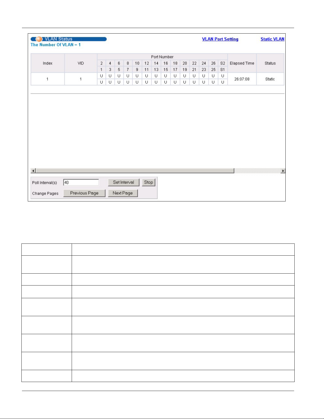
Dimension ES-4024 Ethernet Switch
Figure 7-3 Advanced: VLAN Status
The following table describes the labels in this screen.
Table 7-2 Advanced: VLAN Status
LABEL DESCRIPTION
The Number of
VLAN
Index This is the VLAN index number.
VID This is the VLAN identification number that was configured in the VLAN Setup screen.
Port Number This column displays the ports that are participating in a VLAN. A tagged port is marked as T,
Elapsed Time This field shows how long it has been since a normal VLAN was registered or a static VLAN
Status This field shows how this VLAN was added to the switch; dynamically using GVRP or
This is the number of VLANs configured on the switch.
an untagged port is marked as U and ports not participating in a VLAN in marked as “–“.
was set up.
statically, that is, added as a permanent entry.
Poll Interval(s) The text box displays how often (in seconds) this screen refreshes. You may change the
refresh interval by typing a new number in the text box and then clicking Set Interval.
Stop Click Stop to halt polling statistics.
7-4 VLAN
Page 77

Dimension ES-4024 Ethernet Switch
Table 7-2 Advanced: VLAN Status
LABEL DESCRIPTION
Change Pages Click Previous Page or Next Page to show the previous/next screen if all status information
cannot be seen in one screen.
7.1.5 Configuring VLAN Port Settings
To configure the VLAN settings on a port, click the VLAN Port Setting link in the VLAN Status screen.
Figure 7-4 VLAN: VLAN Port Setting
VLAN 7-5
Page 78

Dimension ES-4024 Ethernet Switch
The following table describes the labels in this screen.
Table 7-3 VLAN: VLAN Port Setting
LABEL DESCRIPTION
GVRP GVRP (GARP VLAN Registration Protocol) is a registration protocol that defines a way for
switches to register necessary VLAN members on ports across the network.
Select this check box to permit VLAN groups beyond the local switch.
Port Isolation Port Isolation allows each port (1 to 26) to communicate only with the CPU management port
but not communicate with each other. All incoming ports are selected while only the CPU
outgoing port is selected. This option is the most limiting but also the most secure.
Port This field displays the port numbers.
Ingress Check Select this check box to activate ingress filtering.
Clear this check box to disable ingress filtering.
PVID Enter a number between 1 and 4094 as the port VLAN ID.
GVRP Select this check box to allow GVRP on this port.
Acceptable
Frame Type
VLAN Trunking Enable VLAN Trunking on ports connected to other switches or routers (but not ports directly
Apply Click Apply to save the changes
Cancel Click Cancel to start configuring the screen again.
Specify the type of frames allowed on a port. Choices are All, Tag Only and Untag Only.
Select All from the drop-down list box to accept all untagged or tagged frames on this port. This
is the default setting.
Select Tag Only to accept only tagged frames on this port. All untagged frames will be dropped.
Select Untag Only to accept only untagged frames on this port. All tagged frames will be
dropped.
connected to end users) to allow frames belonging to unknown VLAN groups to pass through
the switch.
7.1.6 Configuring a VLAN
To configure a new VLAN, click Static VLAN in the VLAN Status screen to display the screen as shown next.
7-6 VLAN
Page 79

Dimension ES-4024 Ethernet Switch
Figure 7-5 VLAN: Static VLAN
The following table describes the labels in this screen.
VLAN 7-7
Page 80

Dimension ES-4024 Ethernet Switch
Table 7-4 VLAN: Static VLAN
LABEL DESCRIPTION
ACTIVE Select this check box to activate the VLAN settings.
Name Enter a descriptive name for the VLAN group for identification purposes.
VLAN Group ID Enter the VLAN ID for this static entry; the valid range is between 1 and 4094.
Port The port number identifies the port you are configuring. Ports 25 and 26 are the uplink ports.
Control Select Normal for the port to dynamically join this VLAN group using GVRP. This is the default
selection.
Select Fixed for the port to be a permanent member of this VLAN group.
Select Forbidden if you want to prohibit the port from joining this VLAN group.
Tagging Select TX Tagging if you want the port to tag all outgoing frames transmitted with this VLAN
Group ID.
Add Click Add to add the settings as a new entry in the summary table below.
Cancel Click Cancel to reset the fields.
Clear Click Clear to start configuring the screen again.
7.1.7 Viewing and Editing VLAN Settings
To view a summary of the VLAN configuration, scroll down to the summary table at the bottom of the Static
VLAN screen.
To change the settings of a rule, click a number in the Index field.
Figure 7-6 Static VLAN: Summary Table
The following table describes the labels in the summary table.
Table 7-5 Static VLAN: Summary Table
LABEL DESCRIPTION
VID This field displays the ID number of the VLAN group. Click the number to edit the VLAN settings.
Active This field indicates whether the VLAN settings are enabled (Yes) or disabled (No).
Name This field displays the descriptive name for this VLAN group.
Delete Click Delete to remove the selected entry from the summary table.
Cancel Click Cancel to clear the Delete check boxes.
7-8 VLAN
Page 81

Dimension ES-4024 Ethernet Switch
7.2 Introduction to Port-based VLANs
Port-based VLANs are VLANs where the packet forwarding decision is based on the destination MAC address
and its associated port.
Port-based VLANs require allowed outgoing ports to be defined for each port. Therefore, if you wish to allow two
subscriber ports to talk to each other, for example, between conference rooms in a hotel, you must define the
egress (an egress port is an outgoing port, that is, a port through which a data packet leaves) for both ports.
Port-based VLANs are specific only to the switch on which they were created.
When you activate port-based VLAN, the ES uses a default VLAN ID of 1. You cannot change it.
In screens (such as IP Setup and Filtering) that require a VID, you must enter 1 as the VID.
The port-based VLAN setup screen is shown next. The CPU management port forms a VLAN with all Ethernet
ports.
7.2.1 Configuring a Port-based VLAN
Select Port Based as the VLAN Type in the Switch Setup screen (see Figure 7-2) and then click VLAN from
the navigation panel to display the next screen.
VLAN 7-9
Page 82

Dimension ES-4024 Ethernet Switch
Figure 7-7 Port Based VLAN Setup (All Connected)
7-10 VLAN
Page 83

Dimension ES-4024 Ethernet Switch
Figure 7-8 Port Based VLAN Setup (Port Isolation)
The following table describes the labels in this screen.
VLAN 7-11
Page 84

Dimension ES-4024 Ethernet Switch
Table 7-6 Port Based VLAN Setup
LABEL DESCRIPTION
Setting Wizard Choose from All connected or Port isolation.
All connected means all ports can communicate with each other, that is, there are no virtual
LANs. All incoming and outgoing ports are selected (Figure 7-7). This option is the most flexible
but also the least secure.
Port isolation means that each port can only communicate with the CPU management port and
cannot communicate with each other. All incoming ports are selected while only the CPU
outgoing port is selected (Figure 7-8). This option is the most limiting but also the most secure.
After you make your selection, click Apply (top right of screen) to display the screens as
mentioned above. You can still customize these settings by adding/deleting incoming or outgoing
ports, but you must also click Apply at the bottom of the screen.
Incoming These are the ingress ports; an ingress port is an incoming port, that is, a port through which a
data packet enters. If you wish to allow two subscriber ports to talk to each other, you must define
the ingress port for both ports. The numbers in the top row denote the incoming port for the
corresponding port listed on the left (its outgoing port). CPU refers to the switch management
port. By default it forms a VLAN with all Ethernet ports. If it does not form a VLAN with a particular
port then the switch cannot be managed from that port.
Outgoing These are the egress ports; an egress port is an outgoing port, that is, a port through which a
data packet leaves. If you wish to allow two subscriber ports to talk to each other, you must define
the egress port for both ports. CPU refers to the switch management port. By default it forms a
VLAN with all Ethernet ports. If it does not form a VLAN with a particular port then the switch
cannot be managed from that port.
Apply Click Apply to save the changes.
Cancel Click Cancel to start configuring the screen again.
7-12 VLAN
Page 85
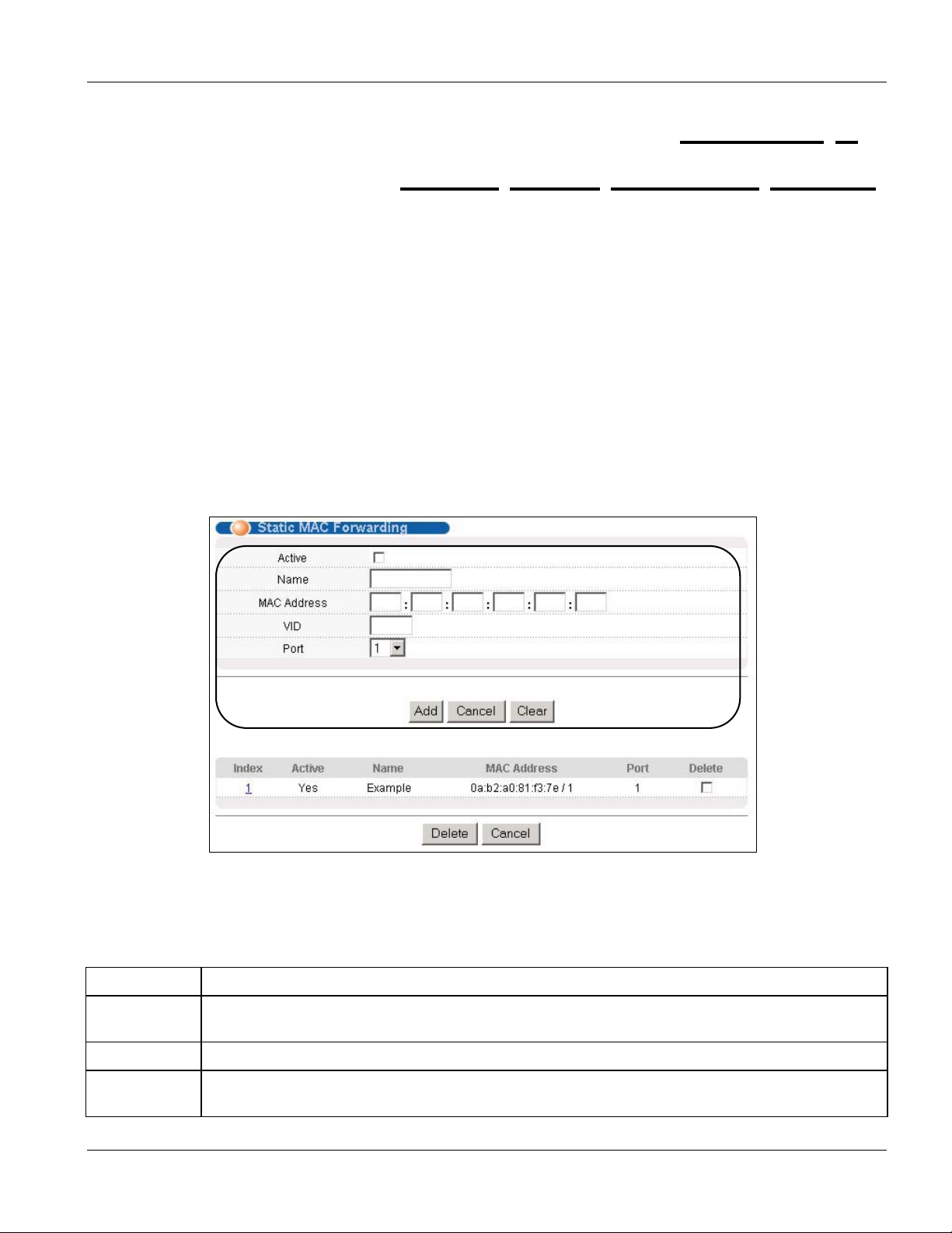
Dimension ES-4024 Ethernet Switch
Chapter 8
Static
Use these screens to configure static MAC address forwarding.
MAC Forward Setup
8.1 Introduction to Static MAC Forward Setup
A static MAC address is an address that has been manually entered in the MAC address learning table. Static
MAC addresses do not age out. When you set up static MAC address rules, you are setting static MAC addresses
for a port. This may reduce the need for broadcasting.
8.2 Configuring Static MAC Forwarding
Click Advanced Applications, Static MAC Forwarding in the navigation panel to display the configuration
screen as shown.
Figure 8-1 Advanced: Static MAC Forwarding
The following table describes the labels in this screen.
Table 8-1 Advanced: Static MAC Forwarding
LABEL DESCRIPTION
Active Select this check box to activate your rule. You may temporarily deactivate a rule without deleting
it by clearing this check box.
Name Enter a descriptive name for identification purposes for this static MAC address forwarding rule.
MAC Address Enter the MAC address in valid MAC address format, that is, six hexadecimal character pairs.
Static MAC addresses do not age out.
Static MAC Forward Setup 8-1
Page 86

Dimension ES-4024 Ethernet Switch
Table 8-1 Advanced: Static MAC Forwarding
LABEL DESCRIPTION
VID Enter the VLAN identification number.
Port Select a port where the MAC address entered in the previous field will be automatically forwarded.
Add After you set the fields above, click Add to insert a new rule.
Cancel Click Cancel to reset the fields.
Clear Click Clear to begin configuring this screen afresh.
8.3 Viewing and Editing Static MAC Forwarding Rules
To view a summary of the rule configuration, scroll down to the summary table at the bottom of the Static MAC
Forwarding screen.
To change the settings of a rule, click a number in the Index field.
Figure 8-2 Static MAC Forwarding: Summary Table
The following table describes the labels in the summary table.
Table 8-2 Static MAC Forwarding: Summary Table
LABEL DESCRIPTION
Index Click an index number to modify a static MAC address rule for a port.
Active This field displays whether this static MAC address forwarding rule is active (Yes) or not (No). You
may temporarily deactivate a rule without deleting it.
Name This field displays the descriptive name for identification purposes for this static MAC address-
forwarding rule.
MAC Address This field displays the MAC address that will be forwarded and the VLAN identification number to
which the MAC address belongs.
Port This field displays the port where the MAC address shown in the next field will be forwarded.
Delete Click Delete to remove the selected entry from the summary table.
Cancel Click Cancel to clear the Delete check boxes.
8-2 Static MAC Forward Setup
Page 87

Dimension ES-4024 Ethernet Switch
Chapter 9
Filtering
This chapter discusses static IP and MAC address port filtering.
9.1 Introduction to Filtering
Port filtering means sifting traffic from one or all ports to one or all ports based on the source and/or destination IP
and/or MAC addresses and VLAN group.
9.1.1 Note About Configuration
The following rules apply when configuring filtering.
• The rule applies to traffic flowing in both directions if both a source and destination are specified.
• The rule applies to traffic flowing in one direction if either a source or destination is specified.
• No any-to-any rules are allowed. That is, you cannot select Ignore for both the source and destination ports.
• No blank rules are allowed. If you do not select Ignore, you must set the related fields.
9.2 Configuring a Filtering Rule
Click Advanced Application, Filtering in the navigation panel to display the screen as shown next.
Filtering 9-1
Page 88

Dimension ES-4024 Ethernet Switch
Figure 9-1 Filtering
The following table describes the related labels in this screen.
Table 9-1 Filtering
LABEL DESCRIPTION
Active Make sure to select this check box to activate your rule. You may temporarily deactivate a rule
without deleting it by deselecting this check box.
9-2 Filtering
Page 89

Dimension ES-4024 Ethernet Switch
Table 9-1 Filtering
LABEL DESCRIPTION
Name Type a descriptive name for this rule. This is for identification purpose only.
Rule Specify to which network layer (Layer 2 or Layer 3) this rule applies.
Layer 2
Set the related fields when you select Layer 2 in the Rule field.
The VID for the source and destination must be the same.
Protocol Select the protocol traffic to which this rule applies.
Source The next three fields pertain to the source MAC address and source port.
Ignore Click this check box to ignore any traffic from all source ports.
MAC Address Select Any MAC/VID to apply the rule to all MAC address and VLAN group identification
numbers.
To specify a source, select the second choice and type a MAC address in valid MAC address
format (six hexadecimal character pairs) and then enter the VLAN group identification number.
Port Select the port to which the rule should be applied. You may choose one port only or all ports
(All Ports).
Destination The next three fields pertain to the destination MAC address and destination port.
Ignore Click this check box to ignore any traffic to all destination ports.
MAC Address Select Any MAC/VID to apply the rule to all MAC address and VLAN group identification
numbers.
To specify a destination, select the second choice and type a MAC address in valid MAC
address format (six hexadecimal character pairs) and then enter the VLAN group identification
number.
Port Select the port to which the rule should be applied. You may choose one port only or all ports
(All Ports).
Layer 3
Set the related fields below when you select Layer 3 in the Rule field.
Protocol Select the protocol traffic to which this rule applies.
Source The next three fields pertain to the source IP address and source port.
Ignore Click this check box to ignore any traffic from all source ports.
IP
Enter a source IP address in dotted decimal notation.
Address/Address
Specify the address prefix by entering the number of ones in the subnet mask.
Prefix
Filtering 9-3
Page 90

Dimension ES-4024 Ethernet Switch
A
Table 9-1 Filtering
LABEL DESCRIPTION
Socket Number
You must set the IP Address/Address Prefix fields and select either UDP or TCP in
the Protocol field before you can configure the socket number.
Select Any to apply to all TCP/UDP protocol port numbers or select the second option and enter
a TCP/UDP protocol port number.
Destination The next three fields pertain to the destination IP address and destination port.
Ignore Click this check box to ignore any traffic to all destination ports.
IP
Enter a destination IP address in dotted decimal notation.
ddress/Address
Socket Number
Specify the address prefix by entering the number of ones in the subnet mask.
Prefix
You must set the IP Address/Address Prefix fields and select either UDP or TCP in
the Protocol field before you can configure the socket number.
Select Any to apply to all TCP/UDP protocol port numbers or select the second option and enter
a TCP/UDP protocol port number.
Add Click Add to inset the entry to the summary table below.
Cancel Click Cancel to reset the fields back to your previous configuration.
Clear Click Clear to set the above fields back to the factory defaults.
9.3 Viewing and Editing Filter Rules
To view a summary of the rule configuration, scroll down to the summary table at the bottom of the Filtering
screen. To change the settings of a rule, click a number in the Index field.
Figure 9-2 Filtering: Summary Table
The following table describes the labels in the summary table.
Table 9-2 Filtering: Summary Table
LABEL DESCRIPTION
Index This field displays the index number of the rule. Click an index number to edit the rule.
Active This field displays Yes when the rule is activated and No when is it deactivated.
Name This field displays the descriptive name for this rule. This is for identification purpose only.
9-4 Filtering
Page 91

Dimension ES-4024 Ethernet Switch
Table 9-2 Filtering: Summary Table
LABEL DESCRIPTION
Rule This field displays the network layer (Layer 2 or Layer 3) to which this rule applies.
Source For Layer 2 rules, this field displays the source port number, the source MAC address with the VLAN
identification number to which the MAC address belongs or a combination of the two.
For Layer 3 rules, this field displays the source protocol socket number, the source IP address and
address prefix or a combination of the two.
All Entries means all IP/MAC addresses from all ports.
Destination For Layer 2 rules, this field displays the destination port number, the destination MAC address with
the VLAN identification number to which the MAC address belongs or a combination of the two.
For Layer 3 rules, this field displays the source protocol socket number, the source IP address and
address prefix or a combination of the two.
All Entries means all IP/MAC addresses from all ports.
Delete Click Delete to remove the selected entry from the summary table.
Cancel Click Cancel to clear the Delete check boxes.
Filtering 9-5
Page 92

Page 93

Dimension ES-4024 Ethernet Switch
Chapter 10
Spanning
This chapter introduces the Spanning Tree Protocol (STP).
Tree Protocol
10.1 Introduction to Spanning Tree Protocol (STP)
STP detects and breaks network loops and provides backup links between switches, bridges or routers. It allows a
switch to interact with other STP-compliant switches in your network to ensure that only one route exists between
any two stations on the network.
10.1.1 STP Terminology
The root bridge is the base of the spanning tree; it is the bridge with the lowest identifier value (MAC address).
Path cost is the cost of transmitting a frame onto a LAN through that port. It is assigned according to the speed of
the link to which a port is attached. The slower the media, the higher the cost - see the next table.
Table 10-1 STP Path Costs
LINK SPEED RECOMMENDED VALUE RECOMMENDED RANGE ALLOWED RANGE
Path Cost 4Mbps 250 100 to 1000 1 to 65535
Path Cost 10Mbps 100 50 to 600 1 to 65535
Path Cost 16Mbps 62 40 to 400 1 to 65535
Path Cost 100Mbps 19 10 to 60 1 to 65535
Path Cost 1Gbps 4 3 to 10 1 to 65535
Path Cost 10Gbps 2 1 to 5 1 to 65535
On each bridge, the root port is the port through which this bridge communicates with the root. It is the port on
this switch with the lowest path cost to the root (the root path cost). If there is no root port, then this switch has
been accepted as the root bridge of the spanning tree network.
For each LAN segment, a designated bridge is selected. This bridge has the lowest cost to the root among the
bridges connected to the LAN.
10.1.2 How STP Works
After a bridge determines the lowest cost-spanning tree with STP, it enables the root port and the ports that are the
designated ports for connected LANs, and disables all other ports that participate in STP. Network packets are
therefore only forwarded between enabled ports, eliminating any possible network loops.
STP-aware switches exchange Bridge Protocol Data Units (BPDUs) periodically. When the bridged LAN
topology changes, a new spanning tree is constructed.
Spanning Tree Protocol 10-1
Page 94

Dimension ES-4024 Ethernet Switch
Once a stable network topology has been established, all bridges listen for Hello BPDUs (Bridge Protocol Data
Units) transmitted from the root bridge. If a bridge does not get a Hello BPDU after a predefined interval (Max
Age), the bridge assumes that the link to the root bridge is down. This bridge then initiates negotiations with other
bridges to reconfigure the network to re-establish a valid network topology.
10.1.3 STP Port States
STP assigns five port states (see next table) to eliminate packet looping. A bridge port is not allowed to go directly
from blocking state to forwarding state so as to eliminate transient loops.
Table 10-2 STP Port States
PORT STATE DESCRIPTION
Disabled STP is disabled (default).
Blocking Only configuration and management BPDUs are received and processed.
Listening All BPDUs are received and processed.
Learning All BPDUs are received and processed. Information frames are submitted to the learning
process but not forwarded.
Forwarding All BPDUs are received and processed. All information frames are received and forwarded.
10.2 STP Status
Click Advanced Application, Spanning Tree Protocol in the navigation panel to display the status screen as
shown next.
Figure 10-1 Spanning Tree Protocol: Status
10-2 Spanning Tree Protocol
Page 95

Dimension ES-4024 Ethernet Switch
The following table describes the labels in this screen.
Table 10-3 Spanning Tree Protocol: Status
LABEL DESCRIPTION
Spanning Tree Protocol This field displays Running if STP is activated. Otherwise, it displays Down.
Configuration Click Configuration to configure STP settings. Refer to Section 10.2.1.
Bridge Root refers to the base of the spanning tree (the root bridge). Our Bridge is this switch.
This switch may also be the root bridge.
Bridge ID This is the unique identifier for this bridge, consisting of bridge priority plus MAC
address. This ID is the same for Root and Our Bridge if the switch is the root switch.
Hello Time (second) This is the time interval (in seconds) at which the root switch transmits a configuration
message. The root bridge determines Hello Time, Max Age and Forwarding Delay
Max Age (second) This is the maximum time (in seconds) a switch can wait without receiving a
configuration message before attempting to reconfigure.
Forwarding Delay
(second)
Cost to Bridge This is the path cost from the root port on this switch to the root switch.
Port ID This is the priority and number of the port on the switch through which this switch must
Topology Changed
Times
Time Since Last Change This is the time since the spanning tree was last reconfigured.
Poll Interval(s) The text box displays how often (in seconds) this screen refreshes. You may change the
Stop Click Stop to halt STP statistic polling.
This is the time (in seconds) the root switch will wait before changing states (that is,
listening to learning to forwarding).
communicate with the root of the Spanning Tree.
This is the number of times the spanning tree has been reconfigured.
refresh interval by typing a new number in the text box and then clicking Set Interval.
10.2.1 Configuring STP
To configure STP, click the Configuration link in the Spanning Tree Protocol screen as shown next.
Spanning Tree Protocol 10-3
Page 96

Dimension ES-4024 Ethernet Switch
Figure 10-2 Spanning Tree Protocol: Configuration
The following table describes the labels in this screen.
10-4 Spanning Tree Protocol
Page 97

Dimension ES-4024 Ethernet Switch
Table 10-4 Spanning Tree Protocol: Configuration
LABEL DESCRIPTION
Status Click Status to display the Spanning Tree Protocol Status screen (see Figure 10-1).
Active Select this check box to activate STP. Clear this checkbox to disable STP.
Bridge Priority Bridge priority is used in determining the root switch, root port and designated port. The switch with
the highest priority (lowest numeric value) becomes the STP root switch. If all switches have the
same priority, the switch with the lowest MAC address will then become the root switch. Select a
value from the drop-down list box.
The lower the numeric value you assign, the higher the priority for this bridge.
Bridge Priority determines the root bridge, which in turn determines Hello Time, Max Age and
Forwarding Delay.
Hello Time This is the time interval in seconds between BPDU (Bridge Protocol Data Units) configuration
message generations by the root switch. The allowed range is 1 to 10 seconds.
Max Age This is the maximum time (in seconds) a switch can wait without receiving a BPDU before
attempting to reconfigure. All switch ports (except for designated ports) should receive BPDUs at
regular intervals. Any port that ages out STP information (provided in the last BPDU) becomes the
designated port for the attached LAN. If it is a root port, a new root port is selected from among the
switch ports attached to the network. The allowed range is 6 to 40 seconds.
Forwarding
Delay
This is the maximum time (in seconds) a switch will wait before changing states. This delay is
required because every switch must receive information about topology changes before it starts to
forward frames. In addition, each port needs time to listen for conflicting information that would
make it return to a blocking state; otherwise, temporary data loops might result. The allowed range
is 4 to 30 seconds.
As a general rule:
2 * (Forward Delay - 1) >= Max Age >= 2 * (Hello Time + 1)
Port This field displays the port number.
Active Select this check box to activate STP on this port.
Priority Configure the priority for each port here.
Priority decides which port should be disabled when more than one port forms a loop in a switch.
Ports with a higher priority numeric value are disabled first. The allowed range is between 0 and
255 and the default value is 128.
Path Cost Path cost is the cost of transmitting a frame on to a LAN through that port. It is assigned according
to the speed of the bridge. The slower the media, the higher the cost - see Table 10-1 for more
information.
Apply Click Apply to save your changes back to the switch.
Cancel Click Cancel to begin configuring this screen afresh.
Spanning Tree Protocol 10-5
Page 98

Page 99

Dimension ES-4024 Ethernet Switch
Chapter 11
Bandwidth
This chapter shows you how you can cap the maximum bandwidth allowed from specific source(s) to
specified destination(s) using the Bandwidth Control setup screen.
Control
11.1 Introduction to Bandwidth Control
Bandwidth control means defining a maximum allowable bandwidth for traffic flows from specified source(s) to
specified destination(s). Click Advanced Application, Bandwidth Control in the navigation panel to bring up
the screen as shown next.
11.1.1 Note About Configuration
The following rules apply when configuring bandwidth control.
• The rule applies to traffic flowing in both directions if both a source and destination are specified.
• The rule applies to traffic flowing in one direction if either a source or destination is specified.
• No any-to-any rules are allowed, that is, you cannot select Ignore for both the source and destination ports.
• No port-to-port rules are allowed, that is, you cannot set the switch to perform bandwidth management
between two ports on the same switch.
• No blank rules allowed. If you do not select Ignore, you must set the related fields.
Bandwidth Control 11-1
Page 100

Dimension ES-4024 Ethernet Switch
Figure 11-1 Advanced: Bandwidth Control
The following table describes the labels in this screen.
11-2 Bandwidth Control
 Loading...