

Page 1

ES-315
ES-315-F
Intelligent Layer 2 Managed Switch
User’s Guide
Version 3.70
8/2007
Edition 1
DEFAULT LOGIN
IP Address http://192.168.1.1
User Name admin
Password 1234
www.zyxel.com
Page 2

Page 3

About This User's Guide
About This User's Guide
Intended Audience
This manual is intended for people who want to configure the Switch using the web
configurator or via commands. You should have at least a basic knowledge of TCP/IP
networking concepts and topology.
Related Documentation
• Quick Start Guide
The Quick Start Guide is designed to help you get up and running right away. It contains
information on setting up your network and configuring for Internet access.
• Web Configurator Online Help
Embedded web help for descriptions of individual screens and supplementary
information.
" It is recommended you use the web configurator to configure the Switch.
• Supporting Disk
Refer to the included CD for support documents.
• ZyXEL Web Site
Please refer to www.zyxel.com
certifications.
User Guide Feedback
Help us help you. Send all User Guide-related comments, questions or suggestions for
improvement to the following address, or use e-mail instead. Thank you!
The Technical Writing Team,
ZyXEL Communications Corp.,
6 Innovation Road II,
Science-Based Industrial Park,
Hsinchu, 300, Taiwan.
E-mail: techwriters@zyxel.com.tw
for additional support documentation and product
ES-315/ES-315-F User’s Guide
3
Page 4

Document Conventions
Document Conventions
Warnings and Notes
These are how warnings and notes are shown in this User’s Guide.
1 Warnings tell you about things that could harm you or your device.
" Notes tell you other important information (for example, other things you may
need to configure or helpful tips) or recommendations.
Syntax Conventions
• The ES-315 and ES-315-F may be referred to as the “Switch”, the “device”, the “system”
or the “product” in this User’s Guide.
• Product labels, screen names, field labels and field choices are all in bold font.
• A key stroke is denoted by square brackets and uppercase text, for example, [ENTER]
means the “enter” or “return” key on your keyboard.
• “Enter” means for you to type one or more characters and then press the [ENTER] key.
“Select” or “choose” means for you to use one of the predefined choices.
• A right angle bracket ( > ) within a screen name denotes a mouse click. For example,
Maintenance > Log > Log Setting means you first click Maintenance in the navigation
panel, then the Log sub menu and finally the Log Setting tab to get to that screen.
• Units of measurement may denote the “metric” value or the “scientific” value. For
example, “k” for kilo may denote “1000” or “1024”, “M” for mega may denote “1000000”
or “1048576” and so on.
• “e.g.,” is a shorthand for “for instance”, and “i.e.,” means “that is” or “in other words”.
4
ES-315/ES-315-F User’s Guide
Page 5
Document Conventions
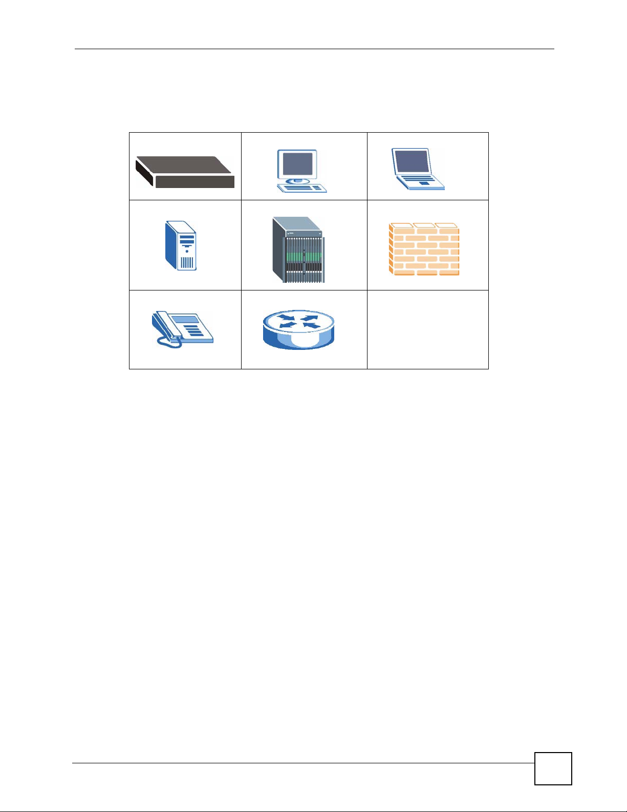
Icons Used in Figures
Figures in this User’s Guide may use the following generic icons. The Switch icon is not an
exact representation of your device.
The Switch Computer Notebook computer
Server DSLAM Firewall
Telephone Router
ES-315/ES-315-F User’s Guide
5
Page 6

Safety Warnings
Safety Warnings
1 For your safety, be sure to read and follow all warning notices and instructions.
• Do NOT use this product near water, for example, in a wet basement or near a swimming
pool.
• Do NOT expose your device to dampness, dust or corrosive liquids.
• Do NOT store things on the device.
• Do NOT install, use, or service this device during a thunderstorm. There is a remote risk
of electric shock from lightning.
• Connect ONLY suitable accessories to the device.
• ONLY qualified service personnel should service or disassemble this device.
• Make sure to connect the cables to the correct ports.
• Place connecting cables carefully so that no one will step on them or stumble over them.
• Always disconnect all cables from this device before servicing or disassembling.
• Use ONLY an appropriate power adaptor or cord for your device. Connect it to the right
supply voltage (for example, 110V AC in North America or 230V AC in Europe).
• Do NOT allow anything to rest on the power adaptor or cord and do NOT place the
product where anyone can walk on the power adaptor or cord.
• Do NOT use the device if the power adaptor or cord is damaged as it might cause
electrocution.
• If the power adaptor or cord is damaged, remove it from the device and the power source.
• Do NOT attempt to repair the power adaptor or cord. Contact your local vendor to order a
new one.
• Do not use the device outside, and make sure all the connections are indoors. There is a
remote risk of electric shock from lightning.
• Caution: Risk of explosion if battery (on the motherboard) is replaced by an incorrect
type. Dispose of used batteries according to the instructions. Dispose them at the
applicable collection point for the recycling of electrical and electronic equipment. For
detailed information about recycling of this product, please contact your local city office,
your household waste disposal service or the store where you purchased the product.
• Do NOT obstruct the device ventilation slots, as insufficient airflow may harm your
device.
• If you wall mount your device, make sure that no electrical lines, gas or water pipes will
be damaged.
6
This product is recyclable. Dispose of it properly.
ES-315/ES-315-F User’s Guide
Page 7

Safety Warnings
ES-315/ES-315-F User’s Guide
7
Page 8

Safety Warnings
8
ES-315/ES-315-F User’s Guide
Page 9

Contents Overview
Contents Overview
Introduction and Hardware ...................................................................................................21
Getting to Know Your Switch ..................................................................................................... 23
Hardware Overview ................................................................................................................... 27
Basic Configuration ...............................................................................................................31
The Web Configurator ............................................................................................................... 33
Initial Setup Example ................................................................................................................. 39
System Status and Port Statistics ..............................................................................................43
Basic Setting ............................................................................................................................. 47
Advanced ................................................................................................................................55
VLAN ......................................................................................................................................... 57
Static MAC Forward Setup ........................................................................................................ 63
Filtering ...................................................................................................................................... 65
Broadcast Storm Control ........................................................................................................... 67
Bandwidth Control ..................................................................................................................... 69
Queuing Method ........................................................................................................................ 71
Multicast .................................................................................................................................... 73
IP Application ......................................................................................................................... 85
Static Route ............................................................................................................................... 87
Management ...........................................................................................................................91
Maintenance .............................................................................................................................. 93
Access Control .......................................................................................................................... 99
Diagnostic .................................................................................................................................113
Syslog .......................................................................................................................................115
MAC Table ................................................................................................................................119
ARP Table ................................................................................................................................ 121
Troubleshooting and Product Specifications ...................................................................125
Troubleshooting ....................................................................................................................... 127
Product Specifications ............................................................................................................. 131
Appendices and Index ........................................................................................................ 137
ES-315/ES-315-F User’s Guide
9
Page 10

Contents Overview
10
ES-315/ES-315-F User’s Guide
Page 11

Table of Contents
Table of Contents
About This User's Guide ..........................................................................................................3
Document Conventions............................................................................................................4
Safety Warnings........................................................................................................................6
Contents Overview ...................................................................................................................9
Table of Contents....................................................................................................................11
List of Figures .........................................................................................................................17
List of Tables...........................................................................................................................19
Part I: Introduction and Hardware ........................................................ 21
Chapter 1
Getting to Know Your Switch.................................................................................................23
1.1 Introduction .......................................................................................................................... 23
1.1.1 Overview .................................................................................................................... 23
1.1.2 IEEE 802.1Q VLAN Application Example .................................................................. 23
1.2 Ways to Manage the Switch ................................................................................................ 24
1.3 Good Habits for Managing the Switch ................................................................................. 24
Chapter 2
Hardware Overview.................................................................................................................27
2.1 LEDs ................................................................................................................................... 27
2.2 Rear and Base Panels ......................................................................................................... 28
Part II: Basic Configuration................................................................... 31
Chapter 3
The Web Configurator ............................................................................................................33
3.1 Introduction .......................................................................................................................... 33
3.2 System Login .................................................................................................................... 33
3.3 The Status Screen .......................................................................................................... 34
3.3.1 Change Your Password .......................................................................................... 36
ES-315/ES-315-F User’s Guide
11
Page 12

Table of Contents
3.4 Saving Your Configuration ................................................................................................... 37
3.5 Switch Lockout .................................................................................................................. 37
3.6 Resetting the Switch ......................................................................................................... 38
3.7 Logging Out of the Web Configurator ................................................................................. 38
3.8 Help ................................................................................................................................... 38
Chapter 4
Initial Setup Example..............................................................................................................39
4.1 Overview .............................................................................................................................. 39
4.1.1 Creating a VLAN ........................................................................................................ 39
4.1.2 Setting Port VID .........................................................................................................40
4.2 Configuring Switch Management IP Address ...................................................................... 41
Chapter 5
System Status and Port Statistics......................................................................................... 43
5.1 Overview .............................................................................................................................. 43
5.2 Port Status Summary ...................................................................................................... 43
5.2.1 Status: Port Details ................................................................................................44
Chapter 6
Basic Setting ..........................................................................................................................47
6.1 Overview .............................................................................................................................. 47
6.2 System Information ........................................................................................................... 47
6.3 General Setup ................................................................................................................. 48
6.4 Introduction to VLANs ........................................................................................................ 49
6.5 Switch Setup Screen ........................................................................................................ 49
6.6 IP Setup .............................................................................................................................. 51
6.6.1 Management IP Addresses ........................................................................................ 51
6.7 Port Setup .......................................................................................................................... 53
Part III: Advanced................................................................................... 55
Chapter 7
VLAN ........................................................................................................................................57
7.1 Introduction to IEEE 802.1Q Tagged VLANs .................................................................. 57
7.1.1 Forwarding Tagged and Untagged Frames ................................................................ 57
7.2 Static VLAN ......................................................................................................................... 58
7.2.1 Static VLAN Status .................................................................................................... 58
7.2.2 Static VLAN Details ................................................................................................... 58
7.2.3 Configure a Static VLAN ........................................................................................ 59
7.2.4 Configure VLAN Port Settings ................................................................................ 61
12
ES-315/ES-315-F User’s Guide
Page 13

Table of Contents
Chapter 8
Static MAC Forward Setup.....................................................................................................63
8.1 Overview .............................................................................................................................. 63
8.2 Configuring Static MAC Forwarding ............................................................................... 63
Chapter 9
Filtering....................................................................................................................................65
9.1 Configure a Filtering Rule ................................................................................................. 65
Chapter 10
Broadcast Storm Control .......................................................................................................67
10.1 Broadcast Storm Control Setup ........................................................................................ 67
Chapter 11
Bandwidth Control..................................................................................................................69
11.1 Bandwidth Control Overview ............................................................................................ 69
11.2 Bandwidth Control Setup ...................................................................................................69
Chapter 12
Queuing Method......................................................................................................................71
12.1 Queuing Method Overview ............................................................................................... 71
12.1.1 Strictly Priority Queuing ............................................................................................ 71
12.1.2 Weighted Fair Queuing ............................................................................................ 71
12.2 Configuring Queuing .......................................................................................................... 72
Chapter 13
Multicast ..................................................................................................................................73
13.1 Multicast Overview ........................................................................................................... 73
13.1.1 IP Multicast Addresses ............................................................................................. 73
13.1.2 IGMP Filtering ..........................................................................................................73
13.1.3 IGMP Snooping ....................................................................................................... 73
13.2 Multicast Status ................................................................................................................ 74
13.3 Multicast Setting ............................................................................................................... 74
13.4 IGMP Filtering Profile ....................................................................................................... 76
13.5 MVR Overview .................................................................................................................. 77
13.5.1 Types of MVR Ports ................................................................................................. 78
13.5.2 MVR Modes ............................................................................................................. 78
13.5.3 How MVR Works ...................................................................................................... 78
13.6 General MVR Configuration .............................................................................................. 79
13.7 MVR Group Configuration ................................................................................................ 81
13.7.1 MVR Configuration Example .................................................................................... 82
ES-315/ES-315-F User’s Guide
13
Page 14

Table of Contents
Part IV: IP Application............................................................................ 85
Chapter 14
Static Route ............................................................................................................................. 87
14.1 Static Routing Overview .................................................................................................... 87
14.2 Configuring Static Routing ................................................................................................ 87
Part V: Management............................................................................... 91
Chapter 15
Maintenance ............................................................................................................................93
15.1 The Maintenance Screen ................................................................................................ 93
15.2 Load Factory Default ........................................................................................................ 94
15.3 Save Configuration ............................................................................................................ 94
15.4 Reboot System .................................................................................................................. 94
15.5 Firmware Upgrade .......................................................................................................... 95
15.6 Restore a Configuration File ...........................................................................................95
15.7 Backup a Configuration File ........................................................................................... 96
15.8 FTP Command Line ..........................................................................................................96
15.8.1 Filename Conventions ............................................................................................ 97
15.8.2 FTP Command Line Procedure .............................................................................. 97
15.8.3 GUI-based FTP Clients ............................................................................................ 98
15.8.4 FTP Restrictions ...................................................................................................... 98
Chapter 16
Access Control........................................................................................................................99
16.1 Access Control Overview .............................................................................................. 99
16.2 The Access Control Main Screen ...................................................................................... 99
16.3 About SNMP .................................................................................................................. 100
16.3.1 Supported MIBs ................................................................................................... 101
16.3.2 SNMP Traps .......................................................................................................... 101
16.3.3 Configuring SNMP ................................................................................................ 103
16.3.4 Setting Up Login Accounts ................................................................................. 104
16.4 SSH Overview ................................................................................................................. 105
16.5 How SSH works ............................................................................................................... 105
16.6 SSH Implementation on the Switch ................................................................................. 106
16.6.1 Requirements for Using SSH ................................................................................. 106
16.7 Introduction to HTTPS .....................................................................................................107
16.8 HTTPS Example .............................................................................................................. 107
16.8.1 Internet Explorer Warning Messages ..................................................................... 108
16.8.2 Netscape Navigator Warning Messages ................................................................ 108
14
ES-315/ES-315-F User’s Guide
Page 15

Table of Contents
16.8.3 The Main Screen .................................................................................................... 109
16.9 Service Port Access Control ......................................................................................... 109
16.10 Remote Management ................................................................................................110
Chapter 17
Diagnostic.............................................................................................................................. 113
17.1 Diagnostic ........................................................................................................................113
Chapter 18
Syslog .................................................................................................................................... 115
18.1 Syslog Overview ...............................................................................................................115
18.2 Syslog Setup ...................................................................................................................115
18.3 Syslog Server Setup ........................................................................................................116
Chapter 19
MAC Table.............................................................................................................................. 119
19.1 MAC Table Overview .......................................................................................................119
19.2 Viewing the MAC Table ................................................................................................... 120
Chapter 20
ARP Table ..............................................................................................................................121
20.1 ARP Table Overview .......................................................................................................121
20.1.1 How ARP Works .................................................................................................... 121
20.2 Viewing the ARP Table ................................................................................................... 121
Part VI: Troubleshooting and Product Specifications...................... 125
Chapter 21
Troubleshooting....................................................................................................................127
21.1 Power, Hardware Connections, and LEDs ...................................................................... 127
21.2 Switch Access and Login ................................................................................................. 128
Chapter 22
Product Specifications.........................................................................................................131
22.1 General Switch Specifications ......................................................................................... 131
22.2 Wall-mounting Instructions .............................................................................................. 134
Part VII: Appendices and Index ......................................................... 137
Appendix A IP Addresses and Subnetting ...........................................................................139
ES-315/ES-315-F User’s Guide
15
Page 16

Table of Contents
Appendix B Common Services............................................................................................. 149
Appendix C Legal Information ..............................................................................................153
Appendix D Customer Support............................................................................................. 157
Index.......................................................................................................................................163
16
ES-315/ES-315-F User’s Guide
Page 17

List of Figures
List of Figures
Figure 1 Internet Access through the Switch .......................................................................................... 23
Figure 2 Shared Server Using VLAN Example ...................................................................................... 24
Figure 3 Front Panel: ES-315 ................................................................................................................ 27
Figure 4 Front Panel: ES-315-F ............................................................................................................ 27
Figure 5 Rear Panel: ES-315 ................................................................................................................ 28
Figure 6 Rear Panel: ES-315-F ............................................................................................................. 28
Figure 7 Base Panel: ES-315-F ............................................................................................................. 29
Figure 8 Web Configurator: Login ......................................................................................................... 34
Figure 9 Web Configurator Home Screen (Status) ................................................................................34
Figure 10 Change Administrator Login Password .................................................................................37
Figure 11 Web Configurator: Logout Screen ......................................................................................... 38
Figure 12 Initial Setup Network Example: VLAN ................................................................................... 39
Figure 13 Initial Setup Network Example: Port VID ............................................................................... 41
Figure 14 Initial Setup Example: Management IP Address ................................................................... 41
Figure 15 Status .................................................................................................................................... 43
Figure 16 Status > Port Details .............................................................................................................. 44
Figure 17 System Info ........................................................................................................................... 47
Figure 18 Basic Setting > General Setup .............................................................................................. 48
Figure 19 Basic Setting > Switch Setup ................................................................................................ 50
Figure 20 Basic Setting > IP Setup ......................................................................................................... 51
Figure 21 Basic Setting > Port Setup .................................................................................................... 53
Figure 22 Advanced Application > VLAN: VLAN Status ........................................................................ 58
Figure 23 Advanced Application > VLAN > VLAN Detail ........................................................................ 59
Figure 24 Advanced Application > VLAN > Static VLAN ...................................................................... 60
Figure 25 Advanced Application > VLAN > VLAN Port Setting ............................................................. 61
Figure 26 Advanced Application > Static MAC Forwarding ................................................................... 63
Figure 27 Advanced Application > Filtering ........................................................................................... 65
Figure 28 Advanced Application > Broadcast Storm Control ................................................................ 67
Figure 29 Advanced Application > Bandwidth Control .......................................................................... 69
Figure 30 Queuing Method .................................................................................................................... 72
Figure 31 Advanced Application > Multicast .......................................................................................... 74
Figure 32 Advanced Application > Multicast > Multicast Setting ........................................................... 75
Figure 33 Advanced Application > Multicast > Multicast Setting > IGMP Filtering Profile ..................... 77
Figure 34 MVR Network Example ......................................................................................................... 78
Figure 35 MVR Multicast Television Example ....................................................................................... 79
Figure 36 Advanced Application > Multicast > Multicast Setting > MVR ............................................... 80
Figure 37 Advanced Application > Multicast > Multicast Setting > MVR: Group Configuration .............. 81
Figure 38 MVR Configuration Example ................................................................................................. 82
ES-315/ES-315-F User’s Guide
17
Page 18

List of Figures
Figure 39 MVR Configuration Example ................................................................................................. 83
Figure 40 MVR Group Configuration Example ..................................................................................... 83
Figure 41 MVR Group Configuration Example ...................................................................................... 84
Figure 42 Static Routing Overview ........................................................................................................ 87
Figure 43 Static Routing ........................................................................................................................ 88
Figure 44 Maintenance ......................................................................................................................... 93
Figure 45 Load Factory Default: Start .................................................................................................... 94
Figure 46 Reboot System: Confirmation ............................................................................................... 94
Figure 47 Firmware Upgrade ................................................................................................................ 95
Figure 48 Firmware Upgrade Warning ................................................................................................... 95
Figure 49 Restore Configuration ........................................................................................................... 96
Figure 50 Backup Configuration ............................................................................................................ 96
Figure 51 Access Control ...................................................................................................................... 99
Figure 52 SNMP Management Model ................................................................................................ 100
Figure 53 Access Control: SNMP ........................................................................................................ 103
Figure 54 Access Control: Logins ........................................................................................................ 104
Figure 55 SSH Communication Example ............................................................................................. 105
Figure 56 How SSH Works ................................................................................................................... 106
Figure 57 HTTPS Implementation ........................................................................................................ 107
Figure 58 Security Alert Dialog Box (Internet Explorer) ........................................................................108
Figure 59 Security Certificate 1 (Netscape) .......................................................................................... 108
Figure 60 Security Certificate 2 (Netscape) .......................................................................................... 109
Figure 61 Example: Lock Denoting a Secure Connection .................................................................... 109
Figure 62 Access Control: Service Access Control ..............................................................................110
Figure 63 Access Control: Remote Management .................................................................................111
Figure 64 Diagnostic .............................................................................................................................113
Figure 65 Syslog ...................................................................................................................................116
Figure 66 Syslog: Server Setup ............................................................................................................117
Figure 67 MAC Table Flowchart ...........................................................................................................119
Figure 68 MAC Table ........................................................................................................................... 120
Figure 69 ARP Table ........................................................................................................................... 122
Figure 70 Wall-mounting Example: ES-315 .......................................................................................... 134
Figure 71 Wall-mounting Example: ES-315-F ......................................................................................135
Figure 72 Network Number and Host ID .............................................................................................. 140
Figure 73 Subnetting Example: Before Subnetting .............................................................................. 142
Figure 74 Subnetting Example: After Subnetting .................................................................................143
Figure 75 Conflicting Computer IP Addresses Example ...................................................................... 147
Figure 76 Conflicting Computer IP Addresses Example ...................................................................... 147
Figure 77 Conflicting Computer and Router IP Addresses Example .................................................... 148
18
ES-315/ES-315-F User’s Guide
Page 19

List of Tables
List of Tables
Table 1 LED Descriptions ...................................................................................................................... 28
Table 2 Navigation Panel Sub-links Overview ....................................................................................... 35
Table 3 Web Configurator Screen Sub-links Details .............................................................................. 35
Table 4 Navigation Panel Links ............................................................................................................. 35
Table 5 Status ........................................................................................................................................ 43
Table 6 Status: Port Details ................................................................................................................... 45
Table 7 System Info ............................................................................................................................... 47
Table 8 Basic Setting > General Setup .................................................................................................. 48
Table 9 Basic Setting > Switch Setup .................................................................................................... 50
Table 10 IP Setup .................................................................................................................................. 52
Table 11 Basic Setting > Port Setup ...................................................................................................... 53
Table 12 Advanced Application > VLAN: VLAN Status .......................................................................... 58
Table 13 Advanced Application > VLAN > VLAN Detail ........................................................................ 59
Table 14 Advanced Application > VLAN > Static VLAN ......................................................................... 60
Table 15 Advanced Application > VLAN > VLAN Port Setting ............................................................... 61
Table 16 Advanced Application > Static MAC Forwarding ..................................................................... 63
Table 17 Advanced Application > FIltering ............................................................................................ 65
Table 18 Advanced Application > Broadcast Storm Control .................................................................. 67
Table 19 Advanced Application > Bandwidth Control ............................................................................ 69
Table 20 Queuing Method ..................................................................................................................... 72
Table 21 Multicast Status ....................................................................................................................... 74
Table 22 Advanced Application > Multicast > Multicast Setting ............................................................. 75
Table 23 Advanced Application > Multicast > Multicast Setting > IGMP Filtering Profile ...................... 77
Table 24 Advanced Application > Multicast > Multicast Setting > MVR ................................................. 80
Table 25 Advanced Application > Multicast > Multicast Setting > MVR: Group Configuration .............. 82
Table 26 Static Routing .......................................................................................................................... 88
Table 27 Maintenance ........................................................................................................................... 93
Table 28 Filename Conventions ............................................................................................................ 97
Table 29 Access Control Overview ........................................................................................................ 99
Table 30 SNMP Commands ................................................................................................................ 100
Table 31 SNMP System Traps ............................................................................................................. 101
Table 32 SNMP InterfaceTraps ............................................................................................................ 102
Table 33 AAA Traps ............................................................................................................................. 102
Table 34 SNMP IP Traps ..................................................................................................................... 102
Table 35 SNMP Switch Traps .............................................................................................................. 103
Table 36 Access Control: SNMP ......................................................................................................... 103
Table 37 Access Control: Logins ......................................................................................................... 105
Table 38 Access Control: Service Access Control ................................................................................110
ES-315/ES-315-F User’s Guide
19
Page 20

List of Tables
Table 39 Access Control: Remote Management .................................................................................. 111
Table 40 Diagnostic ..............................................................................................................................113
Table 41 Syslog Severity Levels ...........................................................................................................115
Table 42 Syslog ....................................................................................................................................116
Table 43 Syslog: Server Setup .............................................................................................................117
Table 44 MAC Table ............................................................................................................................ 120
Table 45 ARP Table ............................................................................................................................. 122
Table 46 Hardware Specifications ....................................................................................................... 131
Table 47 Firmware Specifications ........................................................................................................ 131
Table 48 Feature Specifications ........................................................................................................... 132
Table 49 Standards Supported ............................................................................................................ 133
Table 50 IP Address Network Number and Host ID Example ............................................................. 140
Table 51 Subnet Masks ....................................................................................................................... 141
Table 52 Maximum Host Numbers ...................................................................................................... 141
Table 53 Alternative Subnet Mask Notation ......................................................................................... 141
Table 54 Subnet 1 ................................................................................................................................ 143
Table 55 Subnet 2 ................................................................................................................................ 144
Table 56 Subnet 3 ................................................................................................................................ 144
Table 57 Subnet 4 ................................................................................................................................ 144
Table 58 Eight Subnets ........................................................................................................................ 144
Table 59 24-bit Network Number Subnet Planning .............................................................................. 145
Table 60 16-bit Network Number Subnet Planning .............................................................................. 145
Table 61 Commonly Used Services ..................................................................................................... 149
20
ES-315/ES-315-F User’s Guide
Page 21

PART I
Introduction and
Hardware
Getting to Know Your Switch (23)
Hardware Overview (27)
21
Page 22

22
Page 23
CHAPTER 1
Getting to Know Your Switch
This chapter introduces the main features and applications of the Switch.
1.1 Introduction
The ES-315 and ES-315-F are intelligent layer 2 Ethernet switches.
• The ES-315 has four 10/100Mbps LAN ports and one 10/100Mbps WAN port.
• The ES-315-F has four 10/100Mbps LAN ports and one Fast Ethernet SFP (Small Formfactor Pluggable) WAN slot.
See Chapter 22 on page 131 for a full list of software features available on the Switch.
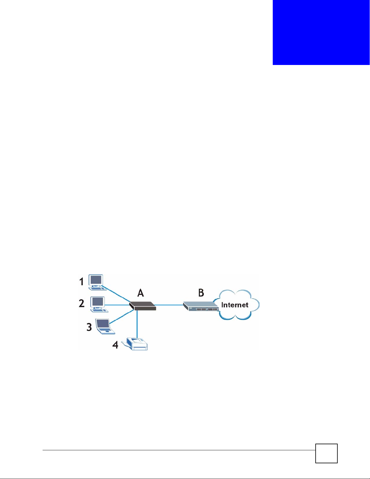
1.1.1 Overview
Use the Switch to connect up to four devices to your network. The following figure shows the
Switch (A) connecting several devices (1 ~ 4) and allowing them to communicate with one
another and access the Internet through the Internet Service Provider’s network switch (B).
Figure 1 Internet Access through the Switch
1.1.2 IEEE 802.1Q VLAN Application Example
A VLAN (Virtual Local Area Network) allows a physical network to be partitioned into
multiple logical networks. Stations on a logical network belong to one group. A station can
belong to more than one group. With VLAN, a station cannot directly talk to or hear from
stations that are not in the same group(s) unless such traffic first goes through a router.
For more information on VLANs, refer to Chapter 7 on page 57.
ES-315/ES-315-F User’s Guide
23
Page 24
Chapter 1 Getting to Know Your Switch
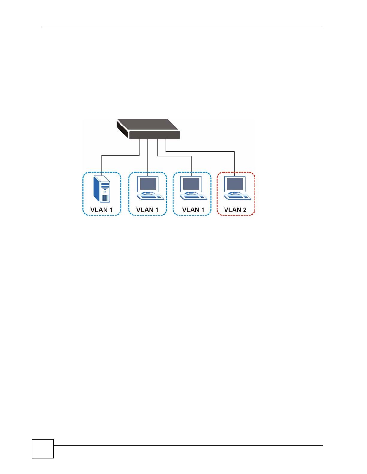
1.1.2.1 Tag-based VLAN Example
Ports in the same VLAN group share the same frame broadcast domain, and thus increase
network performance due to reduced broadcast traffic. VLAN groups can be modified at any
time by adding, moving or changing ports without any re-cabling.
Shared resources such as a server can be used by all ports in the same VLAN as the server. In
the following figure only ports that need access to the server need to be part of VLAN 1. Ports
can belong to other VLAN groups too.
Figure 2 Shared Server Using VLAN Example
1.2 Ways to Manage the Switch
Use any of the following methods to manage the Switch.
• Web Configurator. This is recommended for everyday management of the Switch using a
(supported) web browser. See Chapter 3 on page 33.
• Command Line Interface. Line commands offer an alternative to the web configurator and
in some cases are necessary to configure advanced features. See the Command Reference
Guide.
• FTP. Use FTP for firmware upgrades and configuration backup/restore. See Section 15.8
on page 96.
• SNMP. The Switch can be monitored by an SNMP manager. See Section 16.3 on page
100.
1.3 Good Habits for Managing the Switch
Do the following things regularly to make the Switch more secure and to manage the Switch
more effectively.
• Change the password. Use a password that’s not easy to guess and that consists of
different types of characters, such as numbers and letters.
• Write down the password and put it in a safe place.
24
ES-315/ES-315-F User’s Guide
Page 25

Chapter 1 Getting to Know Your Switch
• Back up the configuration (and make sure you know how to restore it). Restoring an
earlier working configuration may be useful if the device becomes unstable or even
crashes. If you forget your password, you will have to reset the Switch to its factory
default settings. If you backed up an earlier configuration file, you would not have to
totally re-configure the Switch. You could simply restore your last configuration.
ES-315/ES-315-F User’s Guide
25
Page 26

Chapter 1 Getting to Know Your Switch
26
ES-315/ES-315-F User’s Guide
Page 27
CHAPTER 2
Hardware Overview
This section describes the front and rear panels of the switch. See your Quick Start Guide for
information on making hardware connections.
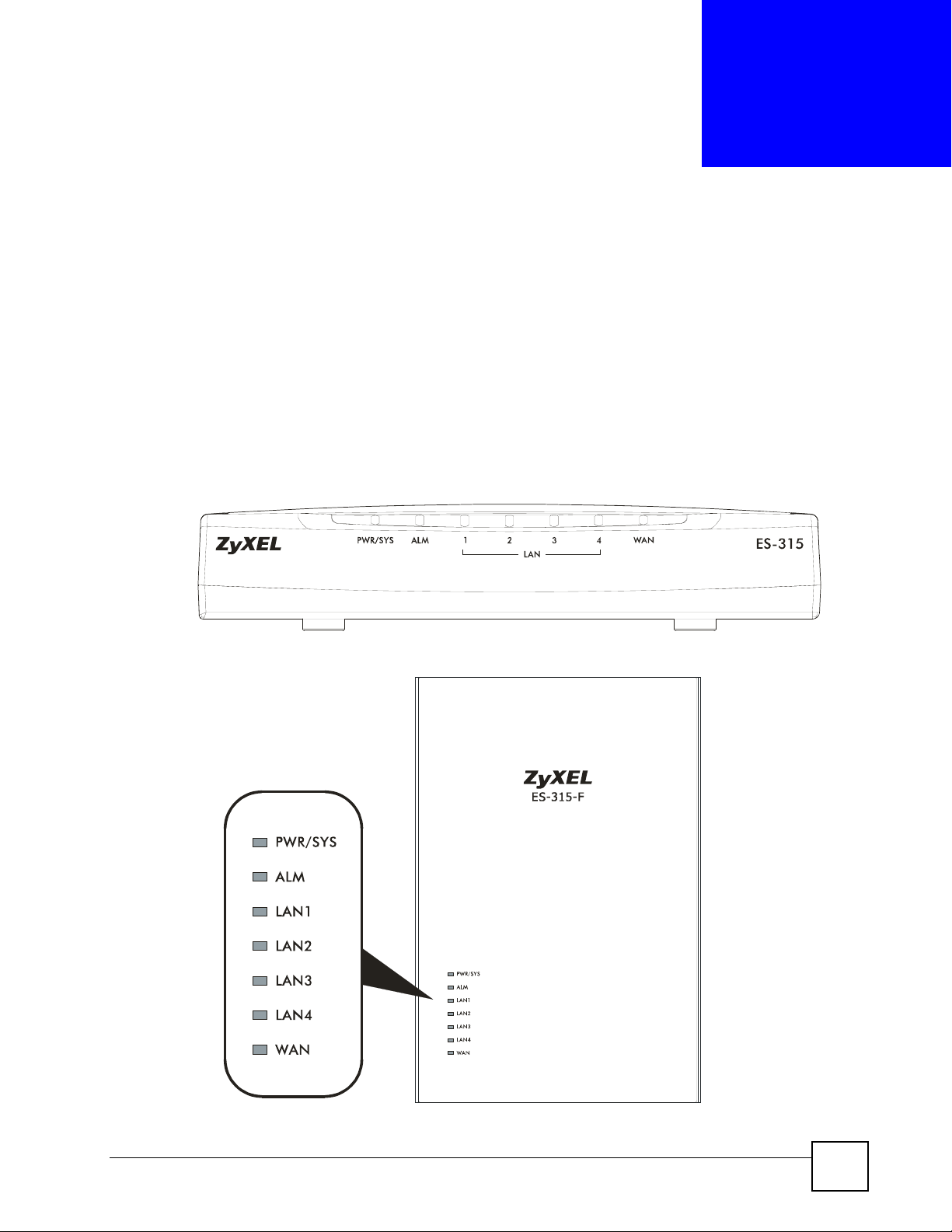
2.1 LEDs
The following figures show the front panels of the ES-315 and ES-315-F.
Figure 3 Front Panel: ES-315
Figure 4 Front Panel: ES-315-F
ES-315/ES-315-F User’s Guide
27
Page 28
Chapter 2 Hardware Overview
The following table describes the Switch’s LEDs.
Table 1 LED Descriptions
LED STATUS DESCRIPTION
PWR/
SYS
ALM On Red The Switch is malfunctioning.
On Green The Switch is receiving power.
Off The Switch is not receiving power.
Off The Switch is functioning normally, or is not receiving power.
LAN1 ~
LAN4
WAN On Steady The Switch has a successful connection on the WAN port.
On Steady The Switch has a successful Ethernet connection on the respective
Blinking The Switch is sending or receiving data on the respective LAN port.
Off There is no device connected to the respective LAN port.
Blinking The Switch is sending or receiving data on the WAN port.
Off There is no device connected to the WAN port.
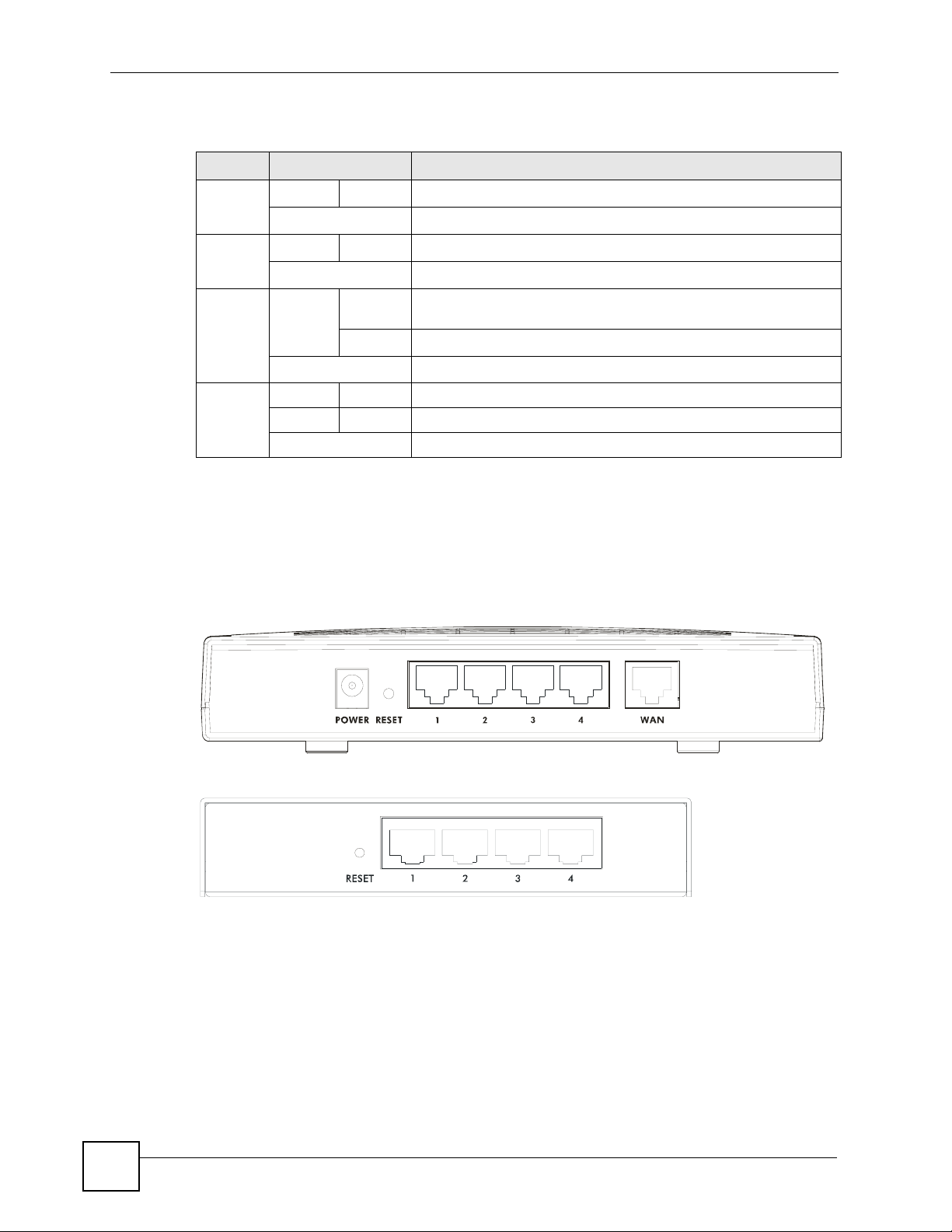
2.2 Rear and Base Panels
The following figures show the rear panels of the ES-315 and ES-315-F, and the base panel of
the ES-315-F.
Figure 5 Rear Panel: ES-315
LAN port.
28
Figure 6 Rear Panel: ES-315-F
ES-315/ES-315-F User’s Guide
Page 29
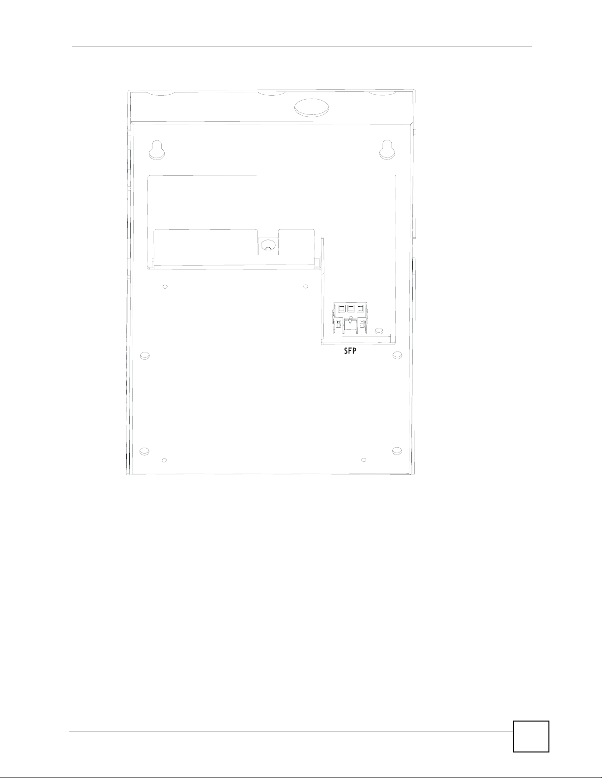
Figure 7 Base Panel: ES-315-F
POWER
Chapter 2 Hardware Overview
ES-315/ES-315-F User’s Guide
29
Page 30

Chapter 2 Hardware Overview
30
ES-315/ES-315-F User’s Guide
Page 31

PART II
Basic Configuration
The Web Configurator (33)
Initial Setup Example (39)
System Status and Port Statistics (43)
Basic Setting (47)
31
Page 32

32
Page 33

CHAPTER 3
The Web Configurator
This section introduces the configuration and functions of the web configurator.
3.1 Introduction
The web configurator is an HTML-based management interface that allows easy Switch setup
and management via Internet browser. Use Internet Explorer 6.0 and later or Netscape
Navigator 7.0 and later versions. The recommended screen resolution is 1024 by 768 pixels.
In order to use the web configurator you need to allow:
• Web browser pop-up windows from your device. Web pop-up blocking is enabled by
default in Windows XP SP (Service Pack) 2.
• JavaScript (enabled by default).
• Java permissions (enabled by default).
3.2 System Login
1 Start your web browser.
2 Type “http://” and the IP address of the Switch (for example, the default is 192.168.1.1)
in the Location or Address field. Press [ENTER].
3 The login screen appears. The default username is admin and associated default
password is 1234. The date and time display as shown if you have not configured a time
server nor manually entered a time and date in the General Setup screen.
ES-315/ES-315-F User’s Guide
33
Page 34

Chapter 3 The Web Configurator
Figure 8 Web Configurator: Login
4 Click OK to view the first web configurator screen.
3.3 The Status Screen
The Status screen is the first screen that displays when you access the web configurator.
The following figure shows the navigating components of a web configurator screen.
Figure 9 Web Configurator Home Screen (Status)
B
C
DE
A
A - Click the menu items to open submenu links, and then click on a submenu link to open the
screen in the main window.
B, C, D, E - These are quick links which allow you to perform certain tasks no matter which
screen you are currently working in.
B - Click this link to save your configuration into the Switch’s nonvolatile memory.
Nonvolatile memory is the configuration of your Switch that stays the same even if the
Switch’s power is turned off.
34
C - Click this link to go to the status page of the Switch.
D - Click this link to logout of the web configurator.
ES-315/ES-315-F User’s Guide
Page 35

Chapter 3 The Web Configurator
E - Click this link to display web help pages. The help pages provide descriptions for all of the
configuration screens.
In the navigation panel, click a main link to reveal a list of submenu links.
Table 2 Navigation Panel Sub-links Overview
BASIC SETTING
ADVANCED
APPLICATION
IP APPLICATION MANAGEMENT
The following table lists the various web configurator screens within the sub-links.
Table 3 Web Configurator Screen Sub-links Details
BASIC SETTING
System Info
General Setup
Switch Setup
IP Setup
Port Setup
ADVANCED
APPLICATION
VLAN
VLAN Port Setting
Static VLAN
Static MAC Forwarding
Filtering
Bandwidth Control
Broadcast Storm Control
Queuing Method
Multicast
Multicast Setting
IGMP Filtering Profile
MVR
Group Configuration
IP APPLICATION MANAGEMENT
Static Routing Maintenance
Firmware Upgrade
Restore Configuration
Backup Configuration
Load Factory Default
Save Configuration
Reboot System
Access Control
SNMP
Logins
Service Access Control
Remote Management
Diagnostic
Syslog
Syslog Server Setup
MAC Table
ARP Table
The following table describes the links in the navigation panel.
Table 4 Navigation Panel Links
LINK DESCRIPTION
Basic Settings
System Info This link takes you to a screen that displays general system information.
General Setup This link takes you to a screen where you can configure general identification
information about the Switch.
ES-315/ES-315-F User’s Guide
35
Page 36

Chapter 3 The Web Configurator
Table 4 Navigation Panel Links (continued)
LINK DESCRIPTION
Switch Setup This link takes you to a screen where you can set up priority queues.
IP Setup This link takes you to a screen where you can configure the IP address, subnet
Port Setup This link takes you to a screen where you can configure settings for individual
Advanced Application
VLAN This link takes you to screens where you can configure 802.1Q VLAN.
Static MAC
Forwarding
Filtering This link takes you to a screen to set up filtering rules.
Broadcast Storm
Control
Bandwidth
Control
Queuing Method This link takes you to a screen where you can configure queuing with associated
Multicast This link takes you to screens where you can configure various multicast features
IP Application
Static Routing This link takes you to a screen where you can configure static routes. A static route
Management
Maintenance This link takes you to screens where you can perform firmware and configuration
Access Control This link takes you to screens where you can change the system login password
Diagnostic This link takes you to a screen where you can view system logs and test port(s).
Syslog This link takes you to screens where you can setup system logs and a system log
MAC Table This link takes you to a screen where you can view the MAC addresses (and types)
ARP Table This link takes you to a screen where you can view the MAC addresses – IP
mask (necessary for Switch management) and DNS (domain name server).
Switch ports.
This link takes you to a screen where you can configure static MAC addresses for a
port. These static MAC addresses do not age out.
This link takes you to a screen to set up broadcast filters.
This link takes you to a screen where you can cap the maximum bandwidth allowed
from specified source(s) to specified destination(s).
queue weights for each port.
and create multicast VLANs.
defines how the Switch should forward traffic by configuring the TCP/IP parameters
manually.
file maintenance as well as reboot the system.
and configure SNMP and remote management.
server.
of devices attached to what ports and VLAN IDs.
address resolution table.
3.3.1 Change Your Password
After you log in for the first time, it is recommended you change the default administrator
password. Click Management, Access Control and then Logins to display the next screen.
36
ES-315/ES-315-F User’s Guide
Page 37

Figure 10 Change Administrator Login Password
3.4 Saving Your Configuration
Chapter 3 The Web Configurator
When you are done modifying the settings in a screen, click Apply to save your changes to the
run-time memory. Settings in the run-time memory are lost when the Switch’s power is turned
off.
Click the Save link in the upper right hand corner of the web configurator to save your
configuration to nonvolatile memory. Nonvolatile memory refers to the Switch’s storage that
remains even if the Switch’s power is turned off.
" Use the Save link when you are done with a configuration session.
3.5 Switch Lockout
You could block yourself (and all others) from managing the Switch if you do one of the
following:
1 Delete the management VLAN (default is VLAN 1).
2 Filter all traffic to the CPU port.
3 Disable all ports.
4 Misconfigure the text configuration file.
5 Forget the password and/or IP address.
6 Prevent all services from accessing the Switch.
7 Change a service port number but forget it.
ES-315/ES-315-F User’s Guide
37
Page 38

Chapter 3 The Web Configurator
" Be careful not to lock yourself and others out of the Switch. If you do lock
yourself out, you will have to reset the Switch.
3.6 Resetting the Switch
If you lock yourself (and others) from the Switch or forget the administrator password, you
will need to reset the Switch back to the factory defaults.
" When you reset the Switch, all user-configured data is lost.
To reset the Switch, press the RESET button on the rear of the Switch for three to five
seconds, then release it. The Switch restarts. All information is reset to defaults, including the
IP address (192.168.1.1), the username (admin) and the password (1234).
3.7 Logging Out of the Web Configurator
Click Logout in a screen to exit the web configurator. You have to log in with your password
again after you log out. This is recommended after you finish a management session for
security reasons.
Figure 11 Web Configurator: Logout Screen
3.8 Help
The web configurator’s online help has descriptions of individual screens and some
supplementary information.
Click the Help link from a web configurator screen to view an online help description of that
screen.
38
ES-315/ES-315-F User’s Guide
Page 39

CHAPTER 4
Initial Setup Example
This chapter shows how to set up the Switch for an example network.
4.1 Overview
The following lists the configuration steps for the initial setup:
• Create a VLAN
• Set port VLAN ID
• Configure the switch IP management address
4.1.1 Creating a VLAN
VLANs confine broadcast frames to the VLAN group in which the port(s) belongs. You can
do this with tagged static VLAN with fixed port members.
In this example, you want to configure port 1 as a member of VLAN 2.
Figure 12 Initial Setup Network Example: VLAN
ES-315/ES-315-F User’s Guide
39
Page 40

Chapter 4 Initial Setup Example
1 Click Advanced Application and VLAN in the navigation panel and click the Static
VLAN link.
2 In the Static VLAN screen,
select ACTIVE, enter a
descriptive name in the Name
field and enter 2 in the VLAN
Group ID field for the VLAN2
network.
Note: The VLAN Group ID field in
this screen and the VID field
in the IP Setup screen refer
to the same VLAN ID.
3 Since the VLAN2 network is
connected to port 1 on the
switch, select Fixed to configure
port 1 to be a permanent
member of the VLAN only.
4 To ensure that VLAN-unaware devices (such as computers and hubs) can receive frames
properly, clear the TX Tagging check box to set the switch to remove VLAN tags before
sending.
5 Click Add to save the settings to the run-time memory. Settings in the run-time memory
are lost when the Switch’s power is turned off.
4.1.2 Setting Port VID
Use PVID to add a tag to incoming untagged frames received on that port so that the frames
are forwarded to the VLAN group that the tag defines.
In the example network, configure 2 as the port VID on port 1 so that any untagged frames
received on that port get sent to VLAN 2.
40
ES-315/ES-315-F User’s Guide
Page 41

Figure 13 Initial Setup Network Example: Port VID
1 Click Advanced Applications
and VLAN in the navigation
panel. Then click the VLAN
Port Setting link.
2 Enter 2 in the PVID field for
port 1 and click Apply to save
your changes back to the runtime memory. Settings in the
run-time memory are lost
when the Switch’s power is
turned off.
Chapter 4 Initial Setup Example
4.2 Configuring Switch Management IP Address
The default management IP address of the switch is 192.168.1.1. You can configure another IP
address in a different subnet for management purposes. The following figure shows an
example.
Figure 14 Initial Setup Example: Management IP Address
1 Connect your computer to any Ethernet port on the switch. Make sure your computer is
in the same subnet as the switch.
ES-315/ES-315-F User’s Guide
41
Page 42

Chapter 4 Initial Setup Example
2 Open your web browser and enter 192.168.1.1 (the default IP address) in the address bar
to access the web configurator. See Section 3.2 on page 33 for more information.
3 Click Basic Setting and IP
Setup in the navigation panel.
4 Configure the fields in the
Management IP Addresses
section:
For the VLAN2 network, enter
192.168.2.1 as the IP address
and 255.255.255.0 as the subnet
mask.
In the VID field, enter the ID of
the VLAN group to which you
want this management IP
address to belong (“2” in this
example). This is the same as
the VLAN ID you configure in
the Static VLAN screen.
5 Click Add to save your changes
back to the run-time memory.
Settings in the run-time memory
are lost when the Switch’s
power is turned off.
42
ES-315/ES-315-F User’s Guide
Page 43

CHAPTER 5
System Status and Port
Statistics
This chapter describes the system status (web configurator home page) and port details
screens.
5.1 Overview
The home screen of the web configurator displays a port summary with links to each port
showing statistical details.
5.2 Port Status Summary
To view the port statistics, click Status in all web configurator screens to display the Status
screen as shown next.
Figure 15 Status
The following table describes the labels in this screen.
Table 5 Status
LABEL DESCRIPTION
Port This identifies the Ethernet port. Click a port number to display the Port Details
screen (refer to Figure 16 on page 44).
Name This is the name you assigned to this port in the Basic Setting, Port Setup screen.
Link This field displays the speed (either 10M for 10Mbps or 100M for 100Mbps) and the
duplex (F for full duplex or H for half).
ES-315/ES-315-F User’s Guide
43
Page 44

Chapter 5 System Status and Port Statistics
Table 5 Status (continued)
LABEL DESCRIPTION
State This field displays FORWARDING if the link is up, otherwise, it displays STOP.
TxPkts This field shows the number of transmitted frames on this port.
RxPkts This field shows the number of received frames on this port.
Errors This field shows the number of received errors on this port.
Tx KB/s This field shows the number of kilobytes per second transmitted on this port.
Rx KB/s This field shows the number of kilobytes per second received on this port.
Up Time This field shows the total amount of time in hours, minutes and seconds the port has
been up.
Clear Counter Enter a port number and then click Clear Counter to erase the recorded statistical
information for that port, or select Any to clear statistics for all ports.
5.2.1 Status: Port Details
Click a number in the Port column in the Status screen to display individual port statistics.
Use this screen to check status and detailed performance data about an individual port on the
Switch.
Figure 16 Status > Port Details
44
ES-315/ES-315-F User’s Guide
Page 45

Chapter 5 System Status and Port Statistics
The following table describes the labels in this screen.
Table 6 Status: Port Details
LABEL DESCRIPTION
Port Info
Port NO. This field displays the port number you are viewing.
Name This field displays the name of the port.
Link This field displays the speed (either 10M for 10Mbps or 100M for 100Mbps and the
duplex (F for full duplex or H for half duplex). It also shows the cable type (Copper or
Fiber). If the port is not connected, Down displays.
Status This field displays FORWARDING if the link is up, otherwise, it displays STOP.
TxPkts This field shows the number of transmitted frames on this port
RxPkts This field shows the number of received frames on this port
Errors This field shows the number of received errors on this port.
Tx KB/s This field shows the number of kilobytes per second transmitted on this port.
Rx KB/s This field shows the number of kilobytes per second received on this port.
Up Time This field shows the total amount of time the connection has been up.
Tx Packet
The following fields display detailed information about packets transmitted.
TX Packet This field shows the number of good packets (unicast, multicast and broadcast)
transmitted.
Multicast This field shows the number of good multicast packets transmitted.
Broadcast This field shows the number of good broadcast packets transmitted.
Pause This field shows the number of 802.3x Pause packets transmitted.
Rx Packet
The following fields display detailed information about packets received.
RX Packet This field shows the number of good packets (unicast, multicast and broadcast)
received.
Multicast This field shows the number of good multicast packets received.
Broadcast This field shows the number of good broadcast packets received.
Pause This field shows the number of 802.3x Pause packets received.
TX Collision
The following fields display information on collisions while transmitting.
Single This is a count of successfully transmitted packets for which transmission is inhibited
by exactly one collision.
Multiple This is a count of successfully transmitted packets for which transmission was
Excessive This is a count of packets for which transmission failed due to excessive collisions.
Late This is the number of times a late collision is detected, that is, after 512 bits of the
Error Packet The following fields display detailed information about packets received that were in
RX CRC This field shows the number of packets received with CRC (Cyclic Redundant Check)
inhibited by more than one collision.
Excessive collision is defined as the number of maximum collisions before the
retransmission count is reset.
packets have already been transmitted.
error.
error(s).
ES-315/ES-315-F User’s Guide
45
Page 46

Chapter 5 System Status and Port Statistics
Table 6 Status: Port Details (continued)
LABEL DESCRIPTION
Runt This field shows the number of packets received that were too short (shorter than 64
octets), including the ones with CRC errors.
Distribution
64 This field shows the number of packets (including bad packets) received that were 64
octets in length.
65-127 This field shows the number of packets (including bad packets) received that were
128-255 This field shows the number of packets (including bad packets) received that were
256-511 This field shows the number of packets (including bad packets) received that were
512-1023 This field shows the number of packets (including bad packets) received that were
10241518
between 65 and 127 octets in length.
between 128 and 255 octets in length.
between 256 and 511 octets in length.
between 512 and 1023 octets in length.
This field shows the number of packets (including bad packets) received that were
between 1024 and 1518 octets in length.
46
ES-315/ES-315-F User’s Guide
Page 47

CHAPTER 6
Basic Setting
This chapter describes how to configure the System Info, General Setup, Switch Setup, IP
Setup and Port Setup screens.
6.1 Overview
The System Info screen displays general Switch information (such as firmware version
number). The General Setup screen allows you to configure general Switch identification
information. The General Setup screen also allows you to set the system time manually or get
the current time and date from an external server when you turn on your Switch. The real time
is then displayed in the Switch logs. The Switch Setup screen allows you to set up and
configure global Switch features. The IP Setup screen allows you to configure a Switch IP
address in each routing domain, subnet mask(s) and DNS (domain name server) for
management purposes. The Port Setup screen allows you to configure Switch port settings.
6.2 System Information
In the navigation panel, click Basic Setting and System Info to display the screen as shown.
You can check the firmware version number in this screen.
Figure 17 System Info
The following table describes the labels in this screen.
Table 7 System Info
LABEL DESCRIPTION
System Name This field displays the descriptive name of the Switch for identification purposes.
ZyNOS F/W
Ver si on
Ethernet
Address
This field displays the version number of the Switch 's current firmware including the
date created.
This field refers to the Ethernet MAC (Media Access Control) address of the Switch.
ES-315/ES-315-F User’s Guide
47
Page 48

Chapter 6 Basic Setting
6.3 General Setup
Use this screen to configure general settings such as the system name and time. Click Basic
Setting > General Setup in the navigation panel to display the screen as shown.
Figure 18 Basic Setting > General Setup
The following table describes the labels in this screen.
Table 8 Basic Setting > General Setup
LABEL DESCRIPTION
System Name Choose a descriptive name for identification purposes. This name consists of up to
64 printable characters; spaces are allowed.
Location Enter the geographic location of your Switch. You can use up to 32 printable ASCII
Contact Person's
Name
Use Time Server
when Bootup
Time Server IP
Address
Current Time This field displays the time you open this menu (or refresh the menu).
New Time
(hh:min:ss)
Current Date This field displays the date you open this menu.
characters; spaces are allowed.
Enter the name of the person in charge of this Switch. You can use up to 32
printable ASCII characters; spaces are allowed.
Enter the time service protocol that your timeserver uses. Not all time servers
support all protocols, so you may have to use trial and error to find a protocol that
works. The main differences between them are the time format.
When you select the Daytime (RFC 867) format, the Switch displays the day,
month, year and time with no time zone adjustment. When you use this format it is
recommended that you use a Daytime timeserver within your geographical time
zone.
Time (RFC-868) format displays a 4-byte integer giving the total number of
seconds since 1970/1/1 at 0:0:0.
NTP (RFC-1305) is similar to Time (RFC-868).
None is the default value. Enter the time manually. Each time you turn on the
Switch, the time and date will be reset to 2000-1-1 0.0.
Enter the IP address of your timeserver. The Switch searches for the timeserver for
up to 60 seconds. If you select a timeserver that is unreachable, then this screen
will appear locked for 60 seconds. Please wait.
Enter the new time in hour, minute and second format. The new time then appears
in the Current Time field after you click Apply.
48
ES-315/ES-315-F User’s Guide
Page 49

Table 8 Basic Setting > General Setup (continued)
LABEL DESCRIPTION
New Date (yyyymm-dd)
Time Zone Select the time difference between UTC (Universal Time Coordinated, formerly
Apply Click Apply to save your changes to the Switch’s run-time memory. The Switch
Cancel Click Cancel to begin configuring this screen afresh.
Enter the new date in year, month and day format. The new date then appears in
the Current Date field after you click Apply.
known as GMT, Greenwich Mean Time) and your time zone from the drop-down list
box.
loses these changes if it is turned off or loses power, so use the Save link on the
top navigation panel to save your changes to the non-volatile memory when you
are done configuring.
6.4 Introduction to VLANs
A VLAN (Virtual Local Area Network) allows a physical network to be partitioned into
multiple logical networks. Devices on a logical network belong to one group. A device can
belong to more than one group. With VLAN, a device cannot directly talk to or hear from
devices that are not in the same group(s); the traffic must first go through a router.
Chapter 6 Basic Setting
In MTU (Multi-Tenant Unit) applications, VLAN is vital in providing isolation and security
among the subscribers. When properly configured, VLAN prevents one subscriber from
accessing the network resources of another on the same LAN, thus a user will not see the
printers and hard disks of another user in the same building.
VLAN also increases network performance by limiting broadcasts to a smaller and more
manageable logical broadcast domain. In traditional switched environments, all broadcast
packets go to each and every individual port. With VLAN, all broadcasts are confined to a
specific broadcast domain.
" VLAN is unidirectional; it only governs outgoing traffic.
See Chapter 7 on page 57 for information on 802.1Q tagged VLANs.
6.5 Switch Setup Screen
Click Basic Setting and then Switch Setup in the navigation panel to display the screen as
shown. This screen allows you to set priority levels on the Switch. Refer to the chapter on
VLAN.
ES-315/ES-315-F User’s Guide
49
Page 50

Chapter 6 Basic Setting
Figure 19 Basic Setting > Switch Setup
The following table describes the labels in this screen.
Table 9 Basic Setting > Switch Setup
LABEL DESCRIPTION
Priority Queue Assignment
IEEE 802.1p defines up to eight separate traffic types by inserting a tag into a MAC-layer frame that
contains bits to define class of service. Frames without an explicit priority tag are given the default
priority of the ingress port. Use the next fields to configure the priority level-to-physical queue mapping.
The Switch has four physical queues that you can map to the 8 priority levels. On the Switch, traffic
assigned to higher index queues gets through faster while traffic in lower index queues is dropped if
the network is congested.
Priority Level (The following descriptions are based on the traffic types defined in the IEEE 802.1d
standard (which incorporates the 802.1p).
Level 7 Typically used for network control traffic such as router configuration messages.
Level 6 Typically used for voice traffic that is especially sensitive to jitter (jitter is variation in
Level 5 Typically used for video that consumes high bandwidth and is sensitive to jitter.
Level 4 Typically used for controlled load, latency-sensitive traffic such as SNA (Systems
Level 3 Typically used for “excellent effort” or better than best effort and would include
Level 2 This is for “spare bandwidth”.
Level 1 This is typically used for non-critical “background” traffic such as bulk transfers that
Level 0 Typically used for best-effort traffic.
Apply Click Apply to save your changes to the Switch’s run-time memory. The Switch
Cancel Click Cancel to reset the fields.
delay).
Network Architecture) transactions.
important business traffic that can tolerate some delay.
are allowed but that should not affect other applications and users.
loses these changes if it is turned off or loses power, so use the Save link on the top
navigation panel to save your changes to the non-volatile memory when you are
done configuring.
50
ES-315/ES-315-F User’s Guide
Page 51

6.6 IP Setup
Use the IP Setup screen to configure the switch IP address, default gateway device, the
default domain name server and the management VLAN ID. The default gateway specifies the
IP address of the default gateway (next hop) for outgoing traffic.
6.6.1 Management IP Addresses
The switch needs an IP address for it to be managed over the network. The factory default IP
address is 192.168.1.1. The subnet mask specifies the network number portion of an IP
address. The factory default subnet mask is 255.255.255.0.
You can configure up to 5 IP addresses which are used to access and manage the switch from
the ports belonging to the pre-defined VLAN(s); 4 static VLAN addresses and 1 management
VLAN address.
" You must configure a VLAN first.
Chapter 6 Basic Setting
Figure 20 Basic Setting > IP Setup
ES-315/ES-315-F User’s Guide
51
Page 52

Chapter 6 Basic Setting
The following table describes the labels in this screen.
Table 10 IP Setup
LABEL DESCRIPTION
Domain Name
Server
Default Management IP Address
DHCP Client Select this option if you have a DHCP server that can assign the switch an IP
Static IP Address Select this option if you don’t have a DHCP server or if you wish to assign static
IP Address Enter the IP address of your switch in dotted decimal notation for example
IP Subnet Mask Enter the IP subnet mask of your switch in dotted decimal notation for example
Default Gateway Enter the IP address of the default outgoing gateway in dotted decimal notation,
VID Enter the VLAN identification number associated with the switch IP address.
Apply Click Apply to save your changes to the switch’s run-time memory. The switch
Cancel Click Cancel to begin configuring the fields again.
Management IP Addresses
You can create up to 4 IP addresses, which are used to access and manage the switch from the ports
belonging to the pre-defined VLAN(s). You must configure a VLAN first.
IP Address Enter the IP address for managing the switch by the members of the VLAN
IP Subnet Mask Enter the IP subnet mask in dotted decimal notation.
VID Type the VLAN group identification number.
Default Gateway Enter the IP address of the default outgoing gateway in dotted decimal notation.
Add Click Add to insert the entry to the summary table below and save your changes
Cancel Click Cancel to reset the fields to your previous configuration.
Index This field displays the index number of the rule. Click an index number to edit
IP Address This field displays the IP address.
IP Subnet Mask This field displays the subnet mask.
VID This field displays the ID number of the VLAN group.
Default Gateway This field displays the IP address of the default gateway.
DNS (Domain Name System) is for mapping a domain name to its
corresponding IP address and vice versa. Enter a domain name server IP
address in order to be able to use a domain name instead of an IP address.
address, subnet mask, a default gateway IP address and a domain name server
IP address automatically.
IP address information to the switch. You need to fill in the following fields when
you select this option.
192.168.1.1.
255.255.255.0.
for example 192.168.1.254.
This is the VLAN ID of the CPU and is used for management only. The default is
"1". All ports, by default, are fixed members of this "management VLAN" in order
to manage the device from any port. If a port is not a member of this VLAN, then
users on that port cannot access the device. To access the switch make sure
the port that you are connected to is a member of Management VLAN.
loses these changes if it is turned off or loses power, so use the Save link on the
top navigation panel to save your changes to the non-volatile memory when you
are done configuring.
specified in the VID field below.
to the switch’s run-time memory. The switch loses these changes if it is turned
off or loses power, so use the Save link on the top navigation panel to save your
changes to the non-volatile memory when you are done configuring.
the rule.
52
ES-315/ES-315-F User’s Guide
Page 53

Table 10 IP Setup (continued)
LABEL DESCRIPTION
Delete Check the management IP addresses that you want to remove in the Delete
Cancel Click Cancel to clear the selected checkboxes in the Delete column.
6.7 Port Setup
Use this screen to configure Switch port settings. Click Basic Setting and then Port Setup in
the navigation panel to display the configuration screen.
Figure 21 Basic Setting > Port Setup
Chapter 6 Basic Setting
column, then click the Delete button.
The following table describes the labels in this screen.
Tabl e 11 Basic Setting > Port Setup
LABEL DESCRIPTION
Port This is the port index number.
* Settings in this row apply to all ports.
Use this row only if you want to make some settings the same for all ports. Use this
row first to set the common settings and then make adjustments on a port-by-port
basis.
Note: Changes in this row are copied to all the ports as soon as you
make them.
Active Select this check box to enable a port. The factory default for all ports is enabled. A
port must be enabled for data transmission to occur.
Name Enter a descriptive name that identifies this port. You can enter up to 64 alpha-
numerical characters.
Note: Due to space limitation, the port name may be truncated in
some web configurator screens.
Type This field displays 10/100M for Ethernet connections.
ES-315/ES-315-F User’s Guide
53
Page 54

Chapter 6 Basic Setting
Tabl e 11 Basic Setting > Port Setup (continued)
LABEL DESCRIPTION
Speed/Duplex Select the speed and the duplex mode of the Ethernet connection on this port.
Flow Control A concentration of traffic on a port decreases port bandwidth and overflows buffer
802.1p Priority This priority value is added to incoming frames without a (802.1p) priority queue tag.
Apply Click Apply to save your changes to the Switch’s run-time memory. The Switch loses
Cancel Click Cancel to begin configuring this screen afresh.
Choices are Auto, 10M/Half Duplex, 10M/Full Duplex, 100M/Half Duplex and
100M/Full Duplex.
Selecting Auto (auto-negotiation) allows one port to negotiate with a peer port
automatically to obtain the connection speed and duplex mode that both ends
support. When auto-negotiation is turned on, a port on the Switch negotiates with the
peer automatically to determine the connection speed and duplex mode. If the peer
port does not support auto-negotiation or turns off this feature, the Switch determines
the connection speed by detecting the signal on the cable and using half duplex
mode. When the Switch’s auto-negotiation is turned off, a port uses the preconfigured speed and duplex mode when making a connection, thus requiring you to
make sure that the settings of the peer port are the same in order to connect.
memory causing packet discards and frame losses. Flow Control is used to regulate
transmission of signals to match the bandwidth of the receiving port.
The Switch uses IEEE802.3x flow control in full duplex mode and backpressure flow
control in half duplex mode.
IEEE802.3x flow control is used in full duplex mode to send a pause signal to the
sending port, causing it to temporarily stop sending signals when the receiving port
memory buffers fill.
Back Pressure flow control is typically used in half duplex mode to send a "collision"
signal to the sending port (mimicking a state of packet collision) causing the sending
port to temporarily stop sending signals and resend later. Select Flow Control to
enable it.
See Priority Queue Assignment in Table 9 on page 50 for more information.
these changes if it is turned off or loses power, so use the Save link on the top
navigation panel to save your changes to the non-volatile memory when you are done
configuring.
54
ES-315/ES-315-F User’s Guide
Page 55

PART III
Advanced
VLAN (57)
Static MAC Forward Setup (63)
Filtering (65)
Bandwidth Control (69)
Broadcast Storm Control (67)
Queuing Method (71)
Multicast (73)
55
Page 56

56
Page 57

CHAPTER 7
VLAN
This chapter shows you how to configure 802.1Q tagged VLANs.
7.1 Introduction to IEEE 802.1Q Tagged VLANs
A tagged VLAN uses an explicit tag (VLAN ID) in the MAC header to identify the VLAN
membership of a frame across bridges - they are not confined to the switch on which they were
created. The VLAN ID associates a frame with a specific VLAN and provides the information
that switches need to process the frame across the network. A tagged frame is four bytes
longer than an untagged frame and contains two bytes of TPID (Tag Protocol Identifier,
residing within the type/length field of the Ethernet frame) and two bytes of TCI (Tag Control
Information, starts after the source address field of the Ethernet frame).
The CFI (Canonical Format Indicator) is a single-bit flag, always set to zero for Ethernet
switches. If a frame received at an Ethernet port has a CFI set to 1, then that frame should not
be forwarded as it is to an untagged port. The remaining twelve bits define the VLAN ID,
giving a possible maximum number of 4,096 VLANs. Note that user priority and VLAN ID
are independent of each other. A frame with VID (VLAN Identifier) of null (0) is called a
priority frame, meaning that only the priority level is significant and the default VID of the
ingress port is given as the VID of the frame. Of the 4096 possible VIDs, a VID of 0 is used to
identify priority frames and value 4095 (FFF) is reserved, so the maximum possible VLAN
configurations are 4,094.
TPID
2 Bytes
User Priority
3 Bits
CFI
1 Bit
VLAN ID
12 bits
7.1.1 Forwarding Tagged and Untagged Frames
Each port on the Switch is capable of passing tagged or untagged frames. To forward a frame
from an 802.1Q VLAN-aware switch to an 802.1Q VLAN-unaware switch, the Switch first
decides where to forward the frame and then strips off the VLAN tag. To forward a frame from
an 802.1Q VLAN-unaware switch to an 802.1Q VLAN-aware switch, the Switch first decides
where to forward the frame, and then inserts a VLAN tag reflecting the ingress port's default
VID. The default PVID is VLAN 1 for all ports, but this can be changed.
A broadcast frame (or a multicast frame for a multicast group that is known by the system) is
duplicated only on ports that are members of the VID (except the ingress port itself), thus
confining the broadcast to a specific domain.
ES-315/ES-315-F User’s Guide
57
Page 58

Chapter 7 VLAN
7.2 Static VLAN
Use a static VLAN to decide whether an incoming frame on a port should be
• sent to a VLAN group as normal depending on its VLAN tag.
• sent to a group whether it has a VLAN tag or not.
• blocked from a VLAN group regardless of its VLAN tag.
You can also tag all outgoing frames (that were previously untagged) from a port with the
specified VID.
7.2.1 Static VLAN Status
See Section 7.1 on page 57 for more information on Static VLAN. Click Advanced
Application > VLAN from the navigation panel to display the VLAN Status screen as shown
next.
Figure 22 Advanced Application > VLAN: VLAN Status
The following table describes the labels in this screen.
Table 12 Advanced Application > VLAN: VLAN Status
LABEL DESCRIPTION
The Number of
VLAN
Index This is the VLAN index number. Click on an index number to view more VLAN
VID This is the VLAN identification number that was configured in the Static VLAN
Elapsed Time This field shows how long it has been since a normal VLAN was registered or a
Status This field shows how this VLAN was added to the Switch; static - added as a
Change Pages Click Previous or Next to show the previous/next screen if all status information
This is the number of VLANs configured on the Switch.
details.
screen.
static VLAN was set up.
permanent entry or other - added in another way such as via Multicast VLAN
Registration (MVR).
cannot be seen in one screen.
7.2.2 Static VLAN Details
Use this screen to view detailed port settings and status of the VLAN group. See Section 7.1
on page 57 for more information on static VLAN. Click on an index number in the VLAN
Status screen to display VLAN details.
58
ES-315/ES-315-F User’s Guide
Page 59

Figure 23 Advanced Application > VLAN > VLAN Detail
The following table describes the labels in this screen.
Table 13 Advanced Application > VLAN > VLAN Detail
LABEL DESCRIPTION
VLAN Status Click this to go to the VLAN Status screen.
Chapter 7 VLAN
VID This is the VLAN identification number that was configured in the Static VLAN
Port Number This column displays the ports that are participating in a VLAN. A tagged port is
Elapsed Time This field shows how long it has been since a normal VLAN was registered or a
Status This field shows how this VLAN was added to the Switch; static - added as a
screen.
marked as T, an untagged port is marked as U and ports not participating in a VLAN
are marked as “–“.
static VLAN was set up.
permanent entry or other - added in another way such as via Multicast VLAN
Registration (MVR).
7.2.3 Configure a Static VLAN
Use this screen to configure and view 802.1Q VLAN parameters for the Switch. See Section
7.1 on page 57 for more information on static VLAN. To configure a static VLAN, click Static
VLAN in the VLAN Status screen to display the screen as shown next.
ES-315/ES-315-F User’s Guide
59
Page 60

Chapter 7 VLAN
Figure 24 Advanced Application > VLAN > Static VLAN
The following table describes the related labels in this screen.
Table 14 Advanced Application > VLAN > Static VLAN
LABEL DESCRIPTION
ACTIVE Select this check box to activate the VLAN settings.
Name Enter a descriptive name for the VLAN group for identification purposes. This name
VLAN Group ID Enter the VLAN ID for this static entry; the valid range is between 1 and 4094.
Port The port number identifies the port you are configuring.
* Settings in this row apply to all ports.
consists of up to 64 printable characters.
Use this row only if you want to make some settings the same for all ports. Use this
row first to set the common settings and then make adjustments on a port-by-port
basis.
Note: Changes in this row are copied to all the ports as soon as you
make them.
Control Select Normal for the port to not be part of the VLAN group. This is the default
Tx Tagging Select TX Tagging if you want the port to tag all outgoing frames transmitted with
Add Click Add to save your changes to the Switch’s run-time memory. The Switch loses
Cancel Click Cancel to change the fields back to their last saved values.
Clear Click Clear to start configuring the screen again.
selection. On GVRP-capable devices, the Normal status allows the port to join the
VLAN dynamically. However, the Switch does not support GVRP.
Select Fixed for the port to be a permanent member of this VLAN group.
Select Forbidden if you want to prohibit the port from joining this VLAN group.
this VLAN Group ID.
these changes if it is turned off or loses power, so use the Save link on the top
navigation panel to save your changes to the non-volatile memory when you are
done configuring.
60
ES-315/ES-315-F User’s Guide
Page 61

Table 14 Advanced Application > VLAN > Static VLAN (continued)
LABEL DESCRIPTION
VID This field displays the ID number of the VLAN group. Click the number to edit the
VLAN settings.
Active This field indicates whether the VLAN settings are enabled (Ye s) or disabled (No).
Name This field displays the descriptive name for this VLAN group.
Delete Click Delete to remove the selected entry from the summary table.
Cancel Click Cancel to clear the Delete check boxes.
7.2.4 Configure VLAN Port Settings
Use the VLAN Port Setting screen to configure the static VLAN (IEEE 802.1Q) settings on a
port. See Section 7.1 on page 57 for more information on static VLAN. Click the VLAN Port
Setting link in the VLAN Status screen.
Figure 25 Advanced Application > VLAN > VLAN Port Setting
Chapter 7 VLAN
The following table describes the labels in this screen.
Table 15 Advanced Application > VLAN > VLAN Port Setting
LABEL DESCRIPTION
Port This field displays the port number.
* Settings in this row apply to all ports.
Use this row only if you want to make some settings the same for all ports. Use this
row first to set the common settings and then make adjustments on a port-by-port
basis.
Note: Changes in this row are copied to all the ports as soon as you
make them.
Ingress Check If this check box is selected for a port, the Switch discards incoming frames for
VLANs that do not include this port in its member set.
Clear this check box to disable ingress filtering.
PVID Enter a number between 1and 4094 as the port VLAN ID.
ES-315/ES-315-F User’s Guide
61
Page 62

Chapter 7 VLAN
Table 15 Advanced Application > VLAN > VLAN Port Setting (continued)
LABEL DESCRIPTION
Acceptable
Frame Type
Apply Click Apply to save your changes to the Switch’s run-time memory. The Switch
Cancel Click Cancel to begin configuring this screen afresh.
Specify the type of frames allowed on a port. Choices are All, Tag Onl y and Untag
Only.
Select All from the drop-down list box to accept all untagged or tagged frames on
this port. This is the default setting.
Select Tag Only to accept only tagged frames on this port. All untagged frames will
be dropped.
Select Untag Only to accept only untagged frames on this port. All tagged frames
will be dropped.
loses these changes if it is turned off or loses power, so use the Save link on the
top navigation panel to save your changes to the non-volatile memory when you
are done configuring.
62
ES-315/ES-315-F User’s Guide
Page 63

CHAPTER 8
Static MAC Forward Setup
Use these screens to configure static MAC address forwarding.
8.1 Overview
This chapter discusses how to configure forwarding rules based on MAC addresses of devices
on your network.
8.2 Configuring Static MAC Forwarding
A static MAC address is an address that has been manually entered in the MAC address table.
Static MAC addresses do not age out. When you set up static MAC address rules, you are
setting static MAC addresses for a port. This may reduce the need for broadcasting.
Click Advanced Applications > Static MAC Forwarding in the navigation panel to display
the configuration screen as shown.
Figure 26 Advanced Application > Static MAC Forwarding
The following table describes the labels in this screen.
Table 16 Advanced Application > Static MAC Forwarding
LABEL DESCRIPTION
Active Select this check box to activate your rule. You may temporarily deactivate a rule
without deleting it by clearing this check box.
Name Enter a descriptive name for identification purposes for this static MAC address
forwarding rule.
ES-315/ES-315-F User’s Guide
63
Page 64

Chapter 8 Static MAC Forward Setup
Table 16 Advanced Application > Static MAC Forwarding (continued)
LABEL DESCRIPTION
MAC Address Enter the MAC address in valid MAC address format, that is, six hexadecimal
character pairs.
Note: Static MAC addresses do not age out.
VID Enter the VLAN identification number.
Port Enter the port where the MAC address entered in the previous field will be
automatically forwarded.
Add Click Add to save your rule to the Switch’s run-time memory. The Switch loses this
rule if it is turned off or loses power, so use the Save link on the top navigation panel
to save your changes to the non-volatile memory when you are done configuring.
Cancel Click Cancel to reset the fields to their last saved values.
Clear Click Clear to begin configuring this screen afresh.
Index Click an index number to modify a static MAC address rule for a port.
Active This field displays whether this static MAC address forwarding rule is active (Yes) or
not (No). You may temporarily deactivate a rule without deleting it.
Name This field displays the descriptive name for identification purposes for this static MAC
MAC Address This field displays the MAC address that will be forwarded and the VLAN
VID This field displays the ID number of the VLAN group.
Port This field displays the port where the MAC address shown in the next field will be
Delete Click Delete to remove the selected entry from the summary table.
Cancel Click Cancel to clear the Delete check boxes.
address-forwarding rule.
identification number to which the MAC address belongs.
forwarded.
64
ES-315/ES-315-F User’s Guide
Page 65

CHAPTER 9
Filtering
This chapter discusses MAC address port filtering.
9.1 Configure a Filtering Rule
Filtering means sifting traffic going through the Switch based on the source MAC address and
VLAN group (ID).
Click Advanced Application > Filtering in the navigation panel to display the screen as
shown next.
Figure 27 Advanced Application > Filtering
The following table describes the related labels in this screen.
Table 17 Advanced Application > FIltering
LABEL DESCRIPTION
Active Make sure you select this check box to activate your rule. You may temporarily
deactivate a rule without deleting it by deselecting this check box.
Name Type a descriptive name (up to 32 printable ASCII characters) for this rule. This is for
identification only.
MAC Type a MAC address in valid MAC address format, that is, six hexadecimal character
pairs. Traffic to and from the specified MAC address is blocked.
VID Type the VLAN group identification number.
ES-315/ES-315-F User’s Guide
65
Page 66

Chapter 9 Filtering
Table 17 Advanced Application > FIltering (continued)
LABEL DESCRIPTION
Add Click Add to save your changes to the Switch’s run-time memory. The Switch loses
Cancel Click Cancel to reset the fields to your previous configuration.
Clear Click Clear to clear the fields to the factory defaults.
Index This field displays the index number of the rule. Click an index number to change the
Active This field displays Yes when the rule is activated and No when is it deactivated.
Name This field displays the descriptive name for this rule. This is for identification purpose
MAC
Address
VID This field displays the VLAN group identification number.
Delete Check the rule(s) that you want to remove in the Delete column and then click the
Cancel Click Cancel to clear the selected checkbox(es) in the Delete column.
these changes if it is turned off or loses power, so use the Save link on the top
navigation panel to save your changes to the non-volatile memory when you are done
configuring.
settings.
only.
This field displays the source/destination MAC address with the VLAN identification
number to which the MAC address belongs.
Delete button.
66
ES-315/ES-315-F User’s Guide
Page 67

CHAPTER 10
Broadcast Storm Control
This chapter introduces and shows you how to configure the broadcast storm control feature.
10.1 Broadcast Storm Control Setup
Broadcast storm control limits the number of broadcast packets the Switch receives per second
on the ports. When the maximum number of allowable broadcast packets is reached per
second, the subsequent packets are discarded. Enable this feature to reduce broadcast packets
in your network.
Click Advanced Application > Broadcast Storm Control in the navigation panel to display
the screen as shown next.
Figure 28 Advanced Application > Broadcast Storm Control
The following table describes the labels in this screen.
Table 18 Advanced Application > Broadcast Storm Control
LABEL DESCRIPTION
Active Select this check box to enable traffic storm control on the Switch. Clear this check
Bandwidth
Utilization Limit
Port This field displays the port number.
Active Select the check box to enable traffic storm control on the relevant port.
ES-315/ES-315-F User’s Guide
box to disable this feature.
Enter the maximum percentage of bandwidth allowed to be taken up by broadcast
packets.
67
Page 68

Chapter 10 Broadcast Storm Control
Table 18 Advanced Application > Broadcast Storm Control (continued)
LABEL DESCRIPTION
Apply Click Apply to save your changes to the Switch’s run-time memory. The Switch
loses these changes if it is turned off or loses power, so use the Save link on the top
navigation panel to save your changes to the non-volatile memory when you are
done configuring.
Cancel Click Cancel to reset the fields.
68
ES-315/ES-315-F User’s Guide
Page 69

CHAPTER 11
Bandwidth Control
This chapter shows you how you can cap the maximum bandwidth using the Bandwidth
Control screen.
11.1 Bandwidth Control Overview
Bandwidth control means defining a maximum allowable bandwidth for incoming and/or outgoing traffic flows on a port.
11.2 Bandwidth Control Setup
Click Advanced Application > Bandwidth Control in the navigation panel to bring up the
screen as shown next.
Figure 29 Advanced Application > Bandwidth Control
The following table describes the related labels in this screen.
Table 19 Advanced Application > Bandwidth Control
LABEL DESCRIPTION
Active Select this check box to enable bandwidth control on the Switch.
Port This field displays the port number.
ES-315/ES-315-F User’s Guide
69
Page 70

Chapter 11 Bandwidth Control
Table 19 Advanced Application > Bandwidth Control (continued)
LABEL DESCRIPTION
* Settings in this row apply to all ports.
Use this row only if you want to make some settings the same for all ports. Use this
row first to set the common settings and then make adjustments on a port-by-port
basis.
Note: Changes in this row are copied to all the ports as soon as you
Active Select this check box to activate ingress rate limits on this port.
Ingress Rate Specify the maximum bandwidth allowed in kilobits per second (Kbps) for the incoming
traffic flow on a port.
Active Select this check box to activate egress rate limits on this port.
Egress Rate Specify the maximum bandwidth allowed in kilobits per second (Kbps) for the out-
going traffic flow on a port.
Apply Click Apply to save your changes to the Switch’s run-time memory. The Switch loses
these changes if it is turned off or loses power, so use the Save link on the top
navigation panel to save your changes to the non-volatile memory when you are done
configuring.
Cancel Click Cancel to reset the fields.
make them.
70
ES-315/ES-315-F User’s Guide
Page 71

CHAPTER 12
Queuing Method
This chapter introduces the queuing methods supported.
12.1 Queuing Method Overview
Queuing is used to help solve performance degradation when there is network congestion. Use
the Queuing Method screen to configure queuing algorithms for outgoing traffic. See also
Priority Queue Assignment in the Basic > Switch Setup screen and 802.1p Priority in the
Basic > Port Setup screen for related information.
Queuing algorithms allow switches to maintain separate queues for packets from each
individual source or flow and prevent a source from monopolizing the bandwidth.
12.1.1 Strictly Priority Queuing
Strictly Priority Queuing (SPQ) services queues based on priority only. As traffic comes into
the Switch, traffic on the highest priority queue, Q3 is transmitted first. When that queue
empties, traffic on the next highest-priority queue, Q2 is transmitted until Q2 empties, and
then traffic is transmitted on Q1 and so on. If higher priority queues never empty, then traffic
on lower priority queues never gets sent. SP does not automatically adapt to changing network
requirements.
12.1.2 Weighted Fair Queuing
Weighted Fair Queuing is used to guarantee each queue's minimum bandwidth based on its
bandwidth weight (portion) when there is traffic congestion. WFQ is activated only when a
port has more traffic than it can handle. Queues with larger weights get more guaranteed
bandwidth than queues with smaller weights. This queuing mechanism is highly efficient in
that it divides any available bandwidth across the different traffic queues. By default, the
weight for each queue is 1. Guaranteed bandwidth is calculated as follows:
Queue Weight x Port Speed
Total Queue Weight
For example, using the default setting, Q0 on Port 1 gets a guaranteed bandwidth of:
1 x 100 Mbps = 10 Mbps
1+2+3+4
ES-315/ES-315-F User’s Guide
71
Page 72

Chapter 12 Queuing Method
12.2 Configuring Queuing
Click Advanced Application > Queuing Method in the navigation panel.
Figure 30 Queuing Method
The following table describes the labels in this screen.
Table 20 Queuing Method
LABEL DESCRIPTION
Port This label shows the port you are configuring.
Method Select SPQ (Strict Priority Queuing) or WFQ (Weighted Fair Queueing).
Strict Priority Queuing (SPQ) services queues based on priority only. When the
highest priority queue empties, traffic on the next highest-priority queue begins. Q3
has the highest priority and Q0 the lowest.
Weighted Fair Queuing is used to guarantee each queue's minimum bandwidth
based on their bandwidth portion (weight) (the number you configure in the Weight
field). Queues with larger weights get more guaranteed bandwidth than queues with
smaller weights.
Q0~Q3 Weight When you select WFQ, enter the queue weight here. Bandwidth is divided across
the different traffic queues according to their weights. Queues with larger weights get
more service than queues with smaller weights.
Apply Click Apply to save your changes to the Switch’s run-time memory. The Switch
loses these changes if it is turned off or loses power, so use the Save link on the top
navigation panel to save your changes to the non-volatile memory when you are
done configuring.
Cancel Click Cancel to begin configuring this screen afresh.
72
ES-315/ES-315-F User’s Guide
Page 73

CHAPTER 13
Multicast
This chapter shows you how to configure various multicast features.
13.1 Multicast Overview
Traditionally, IP packets are transmitted in one of either two ways - Unicast (1 sender to 1
recipient) or Broadcast (1 sender to everybody on the network). Multicast delivers IP packets
to just a group of hosts on the network.
IGMP (Internet Group Management Protocol) is a network-layer protocol used to establish
membership in a multicast group - it is not used to carry user data. Refer to RFC 1112, RFC
2236 and RFC 3376 for information on IGMP versions 1, 2 and 3 respectively.
13.1.1 IP Multicast Addresses
In IPv4, a multicast address allows a device to send packets to a specific group of hosts
(multicast group) in a different subnetwork. A multicast IP address represents a traffic
receiving group, not individual receiving devices. IP addresses in the Class D range (224.0.0.0
to 239.255.255.255) are used for IP multicasting. Certain IP multicast numbers are reserved by
IANA for special purposes (see the IANA web site for more information).
13.1.2 IGMP Filtering
With the IGMP filtering feature, you can control which IGMP groups a subscriber on a port
can join. This allows you to control the distribution of multicast services (such as content
information distribution) based on service plans and types of subscription.
You can set the Switch to filter the multicast group join reports on a per-port basis by
configuring an IGMP filtering profile and associating the profile to a port.
13.1.3 IGMP Snooping
A Switch can passively snoop on IGMP packets transferred between IP multicast routers/
switches and IP multicast hosts to learn the IP multicast group membership. It checks IGMP
packets passing through it, picks out the group registration information, and configures
multicasting accordingly. IGMP snooping allows the Switch to learn multicast groups without
you having to manually configure them.
ES-315/ES-315-F User’s Guide
73
Page 74

Chapter 13 Multicast
The Switch forwards multicast traffic destined for multicast groups (that it has learned from
IGMP snooping) to ports that are members of that group. IGMP snooping generates no
additional network traffic, allowing you to significantly reduce multicast traffic passing
through your Switch.
13.2 Multicast Status
Click Advanced Applications > Multicast to display the screen as shown. This screen shows
the multicast group information. See Section 13.1 on page 73 for more information on
multicasting.
Figure 31 Advanced Application > Multicast
The following table describes the labels in this screen.
Table 21 Multicast Status
LABEL DESCRIPTION
Index This is the index number of the entry.
VID This field displays the multicast VLAN ID.
Port This field displays the port number that belongs to the multicast group.
Multicast Group This field displays IP multicast group addresses.
13.3 Multicast Setting
Click Advanced Applications > Multicast > Multicast Setting link to display the screen as
shown. See Section 13.1 on page 73 for more information on multicasting.
74
ES-315/ES-315-F User’s Guide
Page 75

Figure 32 Advanced Application > Multicast > Multicast Setting
Chapter 13 Multicast
The following table describes the labels in this screen.
Table 22 Advanced Application > Multicast > Multicast Setting
LABEL DESCRIPTION
IGMP Snooping Use these settings to configure IGMP Snooping.
Active Select Active to enable IGMP Snooping to forward group multicast traffic only to
ports that are members of that group.
Host Timeout Specify the time (from 1 to 16,711,450) in seconds that elapses before the Switch
Leave Timeout Enter an IGMP leave timeout value (from 1 to 16,711,450) in seconds. This
802.1p Priority Select a priority level (0-7) to which the Switch changes the priority in outgoing
IGMP Filtering Select Active to enable IGMP filtering to control which IGMP groups a subscriber
removes an IGMP group membership entry if it does not receive report messages
from the port.
defines how many seconds the Switch waits for an IGMP report before removing
an IGMP snooping membership entry when an IGMP leave message is received
from a host.
IGMP control packets. Otherwise, select No-Change to not replace the priority.
on a port can join.
Note: If you enable IGMP filtering, you must create and assign
IGMP filtering profiles for the ports that you want to allow to
join multicast groups.
Port This field displays the port number.
* Settings in this row apply to all ports.
Use this row only if you want to make some settings the same for all ports. Use
this row first to set the common settings and then make adjustments on a port-byport basis.
ES-315/ES-315-F User’s Guide
Note: Changes in this row are copied to all the ports as soon as
you make them.
75
Page 76

Chapter 13 Multicast
Table 22 Advanced Application > Multicast > Multicast Setting (continued)
LABEL DESCRIPTION
Immed. Leave Select this option to set the Switch to remove this port from the multicast tree
Group Limited Select this option to limit the number of multicast groups this port is allowed to join.
Max Group Num. Enter the number of multicast groups this port is allowed to join. Once a port is
IGMP Filtering
Profile
IGMP Querier
Mode
Apply Click Apply to save your changes to the Switch’s run-time memory. The Switch
Cancel Click Cancel to begin configuring this screen afresh.
when an IGMP version 2 leave message is received on this port.
Select this option if there is only one host connected to this port.
registered in the specified number of multicast groups, any new IGMP join report
frame(s) is dropped on this port.
Select the name of the IGMP filtering profile to use for this port. Otherwise, select
Default to prohibit the port from joining any multicast group.
You can create IGMP filtering profiles in the Multicast > Multicast Setting >
IGMP Filtering Profile screen.
The Switch treats an IGMP query port as being connected to an IGMP multicast
router (or server). The Switch forwards IGMP join or leave packets to an IGMP
query port.
Select Auto to have the Switch use the port as an IGMP query port if the port
receives IGMP query packets.
Select Fixed to have the Switch always use the port as an IGMP query port.
Select this when you connect an IGMP multicast server to the port.
Select Edge to stop the Switch from using the port as an IGMP query port. The
Switch will not keep any record of an IGMP router being connected to this port.
The Switch does not forward IGMP join or leave packets to this port.
loses these changes if it is turned off or loses power, so use the Save link on the
top navigation panel to save your changes to the non-volatile memory when you
are done configuring.
13.4 IGMP Filtering Profile
An IGMP filtering profile specifies a range of multicast groups that clients connected to the
Switch are able to join. A profile contains a range of multicast IP addresses which you want
clients to be able to join. Profiles are assigned to ports (in the Multicast Setting screen).
Clients connected to those ports are then able to join the multicast groups specified in the
profile. Each port can be assigned a single profile. A profile can be assigned to multiple ports.
Click Advanced Applications > Multicast > Multicast Setting > IGMP Filtering Profile
link to display the screen as shown.
76
ES-315/ES-315-F User’s Guide
Page 77

Chapter 13 Multicast
Figure 33 Advanced Application > Multicast > Multicast Setting > IGMP Filtering Profile
The following table describes the labels in this screen.
Table 23 Advanced Application > Multicast > Multicast Setting > IGMP Filtering Profile
LABEL DESCRIPTION
Profile Name Enter a descriptive name for the profile for identification purposes.
To configure additional rule(s) for a profile that you have already added, enter the
profile name and specify a different IP multicast address range.
Start Address Type the starting multicast IP address for a range of multicast IP addresses that
you want to belong to the IGMP filter profile.
End Address Type the ending multicast IP address for a range of IP addresses that you want to
Add Click Add to save the profile to the Switch’s run-time memory. The Switch loses
Clear Click Clear to clear the fields to the factory defaults.
Profile Name This field displays the descriptive name of the profile.
Start Address This field displays the start of the multicast address range.
End Address This field displays the end of the multicast address range.
Delete To delete the profile(s) and all the accompanying rules, select the profile(s) that
Cancel Click Cancel to clear the Delete Profile/Delete Rule check boxes.
belong to the IGMP filter profile.
If you want to add a single multicast IP address, enter it in both the Start Address
and End Address fields.
these changes if it is turned off or loses power, so use the Save link on the top
navigation panel to save your changes to the non-volatile memory when you are
done configuring.
you want to remove in the Delete Profile column, then click the Delete button.
To delete a rule(s) from a profile, select the rule(s) that you want to remove in the
Delete Rule column, then click the Delete button.
13.5 MVR Overview
Multicast VLAN Registration (MVR) is designed for applications (such as Media-on-Demand
(MoD)) that use multicast traffic across an Ethernet ring-based service provider network.
ES-315/ES-315-F User’s Guide
77
Page 78

Chapter 13 Multicast
MVR allows one single multicast VLAN to be shared among different subscriber VLANs on
the network. While isolated in different subscriber VLANs, connected devices can subscribe
to and unsubscribe from the multicast stream in the multicast VLAN. This improves
bandwidth utilization with reduced multicast traffic in the subscriber VLANs and simplifies
multicast group management.
MVR only responds to IGMP join and leave control messages from multicast groups that are
configured under MVR. Join and leave reports from other multicast groups are managed by
IGMP snooping.
The following figure shows a network example. The subscriber VLAN (1, 2 and 3)
information is hidden from the streaming media server, S. In addition, the multicast VLAN
information is only visible to the Switch and S.
Figure 34 MVR Network Example
13.5.1 Types of MVR Ports
In MVR, a source port is a port on the Switch that can send and receive multicast traffic in a
multicast VLAN while a receiver port can only receive multicast traffic. Once configured, the
Switch maintains a forwarding table that matches the multicast stream to the associated
multicast group.
13.5.2 MVR Modes
You can set your Switch to operate in either dynamic or compatible mode.
In dynamic mode, the Switch sends IGMP leave and join reports to the other multicast devices
(such as multicast routers or servers) in the multicast VLAN. This allows the multicast devices
to update the multicast forwarding table to forward or not forward multicast traffic to the
receiver ports.
In compatible mode, the Switch does not send any IGMP reports. In this case, you must
manually configure the forwarding settings on the multicast devices in the multicast VLAN.
13.5.3 How MVR Works
The following figure shows a multicast television example where a subscriber device (such as
a computer) in VLAN 1 receives multicast traffic from the streaming media server, S, via the
Switch. Multiple subscriber devices can connect through a port configured as the receiver on
the Switch.
78
ES-315/ES-315-F User’s Guide
Page 79

Chapter 13 Multicast
When the subscriber selects a television channel, computer A sends an IGMP report to the
Switch to join the appropriate multicast group. If the IGMP report matches one of the
configured MVR multicast group addresses on the Switch, an entry is created in the
forwarding table on the Switch. This maps the subscriber VLAN to the list of forwarding
destinations for the specified multicast traffic.
When the subscriber changes the channel or turns off the computer, an IGMP leave message is
sent to the Switch to leave the multicast group. The Switch sends a query to VLAN 1 on the
receiver port (in this case, a DSL port on the Switch). If there is another subscriber device
connected to this port in the same subscriber VLAN, the receiving port will still be on the list
of forwarding destination for the multicast traffic. Otherwise, the Switch removes the receiver
port from the forwarding table.
Figure 35 MVR Multicast Television Example
13.6 General MVR Configuration
Use the MVR screen to create multicast VLANs and select the receiver port(s) and a source
port for each multicast VLAN. Click Advanced Applications > Multicast > Multicast
Setting > MVR to display the screen as shown next.
" You can create one multicast VLAN and up to 256 multicast rules on the
Switch.
" Your Switch automatically creates a static VLAN (with the same VID) when you
create a multicast VLAN in this screen.
ES-315/ES-315-F User’s Guide
79
Page 80

Chapter 13 Multicast
Figure 36 Advanced Application > Multicast > Multicast Setting > MVR
The following table describes the related labels in this screen.
Table 24 Advanced Application > Multicast > Multicast Setting > MVR
LABEL DESCRIPTION
Active Select this check box to enable MVR to allow one single multicast VLAN to be
shared among different subscriber VLANs on the network.
Name Enter a descriptive name (up to 32 printable ASCII characters) for identification
purposes.
Multicast VLAN IDEnter the VLAN ID (1 to 4094) of the multicast VLAN.
802.1p Priority Select a priority level (0-7) with which the Switch replaces the priority in outgoing
IGMP control packets (belonging to this multicast VLAN).
Mode Specify the MVR mode on the Switch. Choices are Dynamic and Compatible.
Select Dynamic to send IGMP reports to all MVR source ports in the multicast
VLAN.
Select Compatible to set the Switch not to send IGMP reports.
Port This field displays the port number on the Switch.
* Settings in this row apply to all ports.
Use this row only if you want to make some settings the same for all ports. Use this
row first to set the common settings and then make adjustments on a port-by-port
basis.
Note: Changes in this row are copied to all the ports as soon as you
make them.
Source Port Select this option to set this port as the MVR source port that sends and receives
Receiver Port Select this option to set this port as a receiver port that only receives multicast
multicast traffic. All source ports must belong to a single multicast VLAN.
traffic.
80
ES-315/ES-315-F User’s Guide
Page 81

Chapter 13 Multicast
Table 24 Advanced Application > Multicast > Multicast Setting > MVR (continued)
LABEL DESCRIPTION
None Select this option to set the port not to participate in MVR. No MVR multicast traffic
is sent or received on this port.
Tagging Select this checkbox if you want the port to tag the VLAN ID in all outgoing frames
transmitted.
Add Click Add to save your changes to the Switch’s run-time memory. The Switch loses
these changes if it is turned off or loses power, so use the Save link on the top
navigation panel to save your changes to the non-volatile memory when you are
done configuring.
Cancel Click Cancel to begin configuring this screen afresh.
VLAN This field displays the multicast VLAN ID.
Active This field displays whether the multicast group is enabled or not.
Name This field displays the descriptive name for this setting.
Mode This field displays the MVR mode.
Source Port This field displays the source port number(s).
Receiver Port This field displays the receiver port number(s).
802.1p This field displays the priority level.
Delete To delete a multicast VLAN(s), select the rule(s) that you want to remove in the
Delete column, then click the Delete button.
Cancel Click Cancel to clear the Delete check boxes.
13.7 MVR Group Configuration
All source ports and receiver ports belonging to a multicast group can receive multicast data
sent to this multicast group.
Configure MVR IP multicast group address(es) in the Group Configuration screen. Click
Group Configuration in the MVR screen.
Figure 37 Advanced Application > Multicast > Multicast Setting > MVR: Group Configuration
ES-315/ES-315-F User’s Guide
81
Page 82

Chapter 13 Multicast
The following table describes the labels in this screen.
Table 25 Advanced Application > Multicast > Multicast Setting > MVR: Group Configuration
LABEL DESCRIPTION
Multicast
VLAN ID
Name Enter a descriptive name for identification purposes.
Start Address Enter the starting IP multicast address of the multicast group in dotted decimal
End Address Enter the ending IP multicast address of the multicast group in dotted decimal notation.
Add Click Add to save your changes to the Switch’s run-time memory. The Switch loses
Cancel Click Cancel to begin configuring this screen afresh.
MVLAN This field displays the multicast VLAN ID.
Name This field displays the descriptive name for this setting.
Start Address This field displays the starting IP address of the multicast group.
End Address This field displays the ending IP address of the multicast group.
Delete Select Delete Group and click Delete to remove the selected entry(ies) from the table.
Cancel Select Cancel to clear the checkbox(es) in the table.
Select a multicast VLAN ID (that you configured in the MVR screen) from the dropdown list box.
notation.
Refer to Section 13.1.1 on page 73 for more information on IP multicast addresses.
Enter the same IP address as the Start Address field if you want to configure only one
IP address for a multicast group.
Refer to Section 13.1.1 on page 73 for more information on IP multicast addresses.
these changes if it is turned off or loses power, so use the Save link on the top
navigation panel to save your changes to the non-volatile memory when you are done
configuring.
13.7.1 MVR Configuration Example
The following figure shows a network example where ports 1, 2 and 3 on the Switch belong to
VLAN 1. In addition, port 4 belongs to the multicast group with VID 200 to receive multicast
traffic (the News and Movie channels) from the remote streaming media server, S. Computers
A, B and C in VLAN are able to receive the traffic.
Figure 38 MVR Configuration Example
To configure the MVR settings on the Switch, create a multicast group in the MVR screen and
set the receiver and source ports.
82
ES-315/ES-315-F User’s Guide
Page 83

Chapter 13 Multicast
Figure 39 MVR Configuration Example
To set the Switch to forward the multicast group traffic to the subscribers, configure multicast
group settings in the Group Configuration screen. The following figure shows an example
where two multicast groups (News and Movie) are configured for the multicast VLAN 200.
Figure 40 MVR Group Configuration Example
ES-315/ES-315-F User’s Guide
83
Page 84

Chapter 13 Multicast
Figure 41 MVR Group Configuration Example
84
ES-315/ES-315-F User’s Guide
Page 85

PART IV
IP Application
Static Route (87)
85
Page 86

86
Page 87

CHAPTER 14
Static Route
This chapter shows you how to configure static routes.
14.1 Static Routing Overview
IP static routes are used by the Switch to ensure it can respond to management stations not
reachable via the default gateway and to proactively send traffic, for example when sending
SNMP traps or conducting IP connectivity tests using ping.
The Switch uses IP protocol for communication with management stations, for example via a
browser, telnet, SSH or SNMP. The Switch can communicate with the management stations on
the networks behind the default gateway. The figure below shows a Telnet session in network
N1 behind the default gateway R1. Static routes are used to tell the Switch how to
communicate with management stations not reachable via the default gateway. The figure
below shows an SNMP manager behind router R2 in network N2. A static route must be
configured to tell the Switch how to communicate with the SNMP manager in N2.
Figure 42 Static Routing Overview
N1
Telnet
R1
14.2 Configuring Static Routing
Click IP Application > Static Routing in the navigation panel to display the screen as shown.
N2
SNMP
R2
ES-315/ES-315-F User’s Guide
87
Page 88

Chapter 14 Static Route
Figure 43 Static Routing
The following table describes the related labels you use to create a static route.
Table 26 Static Routing
LABEL DESCRIPTION
Active This field allows you to activate/deactivate this static route.
Name Enter a descriptive name (up to 32 printable ASCII characters) for identification
Destination IP
Address
IP Subnet
Mask
Gateway IP
Address
Metric The metric represents the “cost” of transmission for routing purposes. IP routing uses
Add Click Add to insert a new static route to the Switch’s run-time memory. The Switch
Cancel Click Cancel to reset the above fields to your previous configuration.
Clear Click Clear to set the above fields back to the factory defaults.
Index This field displays the index number of the route. Click a number to edit the static
Active This field displays Yes when the static route is activated and NO when it is
Name This field displays the descriptive name for this route. This is for identification
Destination
Address
Subnet Mask This field displays the subnet mask for this destination.
purposes.
This parameter specifies the IP network address of the final destination.
Enter the subnet mask for this destination. Routing is always based on network
number. If you need to specify a route to a single host, use a subnet mask of
255.255.255.255 in the subnet mask field to force the network number to be identical
to the host ID.
Enter the IP address of the gateway. The gateway is an immediate neighbor of your
Switch that will forward the packet to the destination. The gateway must be a router
on the same segment as your Switch.
hop count as the measurement of cost, with a minimum of 1 for directly connected
networks. Enter a number that approximates the cost for this link. The number need
not be precise, but it must be between 1 and 15. In practice, 2 or 3 is usually a good
number.
loses these changes if it is turned off or loses power, so use the Save link on the top
navigation panel to save your changes to the non-volatile memory when you are done
configuring.
route entry.
deactivated.
purposes only.
This field displays the IP network address of the final destination.
88
ES-315/ES-315-F User’s Guide
Page 89

Chapter 14 Static Route
Table 26 Static Routing (continued)
LABEL DESCRIPTION
Gateway
Address
Metric This field displays the cost of transmission for routing purposes.
Delete Click Delete to remove the selected entry from the summary table.
Cancel Click Cancel to clear the Delete check boxes.
This field displays the IP address of the gateway. The gateway is an immediate
neighbor of your Switch that will forward the packet to the destination.
ES-315/ES-315-F User’s Guide
89
Page 90

Chapter 14 Static Route
90
ES-315/ES-315-F User’s Guide
Page 91

PART V
Management
Maintenance (93)
Access Control (99)
Diagnostic (113)
Syslog (115)
MAC Table (119)
ARP Table (121)
91
Page 92

92
Page 93

CHAPTER 15
Maintenance
This chapter explains how to configure the screens that let you maintain the firmware and
configuration files.
15.1 The Maintenance Screen
Use this screen to manage firmware and your configuration files. Click Management >
Maintenance in the navigation panel to open the following screen.
Figure 44 Maintenance
The following table describes the labels in this screen.
Table 27 Maintenance
LABEL DESCRIPTION
Current This field displays which configuration is currently operating on the Switch. At the time
Firmware
Upgrade
Restore
Configuration
Backup
Configuration
Load Factory
Default
Save
Configuration
Reboot
System
of writing, the Switch supports a single configuration.
Click Click Here to go to the Firmware Upgrade screen.
Click Click Here to go to the Restore Configuration screen.
Click Click Here to go to the Backup Configuration screen.
Click Click Here to reset the configuration to the factory default settings.
Click Config 1 to save the current configuration settings to Configuration 1 on the
Switch.
Click Config 1 to reboot the system and load Configuration 1 on the Switch.
Note: Make sure to click the Save button in any screen to save your
settings to the current configuration on the Switch.
ES-315/ES-315-F User’s Guide
93
Page 94

Chapter 15 Maintenance
15.2 Load Factory Default
Follow the steps below to reset the Switch back to the factory defaults.
1 In the Maintenance screen, click the Click Here button next to Load Factory Default
to clear all Switch configuration information you configured and return to the factory
defaults.
2 Click OK to reset all Switch configurations to the factory defaults.
Figure 45 Load Factory Default: Start
3 In the web configurator, click the Save button to make the changes take effect. If you
want to access the Switch’s web configurator again, you may need to change the IP
address of your computer to be in the same subnet as that of the default Switch IP
address (192.168.1.1).
15.3 Save Configuration
Click Config 1 to save the current configuration settings permanently to the Switch.
Alternatively, click Save on the top right-hand corner in any screen to save the configuration
changes to the current configuration.
" Clicking the Apply or Add button does NOT save the changes permanently.
All unsaved changes are erased after you reboot the Switch.
15.4 Reboot System
Reboot System allows you to restart the Switch without physically turning the power off. It
also allows you to load the configuration file when you reboot. Follow the steps below to
reboot the Switch.
1 In the Maintenance screen, click the Config 1 button next to Reboot System to reboot
and load configuration one. The following screen displays.
Figure 46 Reboot System: Confirmation
94
ES-315/ES-315-F User’s Guide
Page 95

Chapter 15 Maintenance
2 Click OK again and then wait for the Switch to restart. This takes up to two minutes.
This does not affect the Switch’s configuration.
15.5 Firmware Upgrade
Make sure you have downloaded (and unzipped) the correct model firmware and version to
your computer before uploading to the device.
1 Be sure to upload firmware for the correct model as uploading firmware for the
wrong model may damage your device.
From the Maintenance screen, click Firmware Upgrade. The following screen displays.
Figure 47 Firmware Upgrade
Type the path and file name of the firmware file you wish to upload to the Switch in the File
Path text box or click Browse to locate it. Click Upgrade to load the new firmware and reboot
the Switch. The following screen displays.
Figure 48 Firmware Upgrade Warning
After the firmware upgrade process is complete, see the System Info screen to verify your
current firmware version number. You may need to log in to the Switch again.
15.6 Restore a Configuration File
Restore a previously saved configuration from your computer to the Switch using the Restore
Configuration screen.
ES-315/ES-315-F User’s Guide
95
Page 96

Chapter 15 Maintenance
Figure 49 Restore Configuration
Type the path and file name of the configuration file you wish to restore in the File Path text
box or click Browse to display the Choose File screen (below) from which you can locate it.
After you have specified the file, click Restore. "config" is the name of the configuration file
on the Switch, so your backup configuration file is automatically renamed when you restore
using this screen.
15.7 Backup a Configuration File
Backing up your Switch configurations allows you to create various “snap shots” of your
device which you can restore later.
Back up your current Switch configuration to a computer using the Backup Configuration
screen.
Figure 50 Backup Configuration
Follow the steps below to back up the current Switch configuration to your computer in this
screen.
1 Click Backup.
2 Click Save to display the Save As screen.
3 Choose a location to save the file on your computer from the Save in drop-down list box
and type a descriptive name for it in the File name list box. Click Save to save the
configuration file to your computer.
15.8 FTP Command Line
This section shows some examples of uploading to or downloading files from the Switch using
FTP commands. First, understand the filename conventions.
96
ES-315/ES-315-F User’s Guide
Page 97

15.8.1 Filename Conventions
The configuration file (also known as the romfile or ROM) contains the factory default
settings in the screens such as password, Switch setup, IP Setup, and so on. Once you have
customized the Switch’s settings, they can be saved back to your computer under a filename of
your choosing.
ZyNOS (ZyXEL Network Operating System sometimes referred to as the “ras” file) is the
system firmware and has a “bin” filename extension.
Table 28 Filename Conventions
FILE TYPE
Configuration File config This is the configuration filename on the Switch.
Firmware ras *.bin This is the generic name for the ZyNOS firmware on
15.8.1.1 Example FTP Commands
ftp> put firmware.bin ras
INTERNAL
NAME
EXTERNAL
NAME
Chapter 15 Maintenance
DESCRIPTION
Uploading the config file replaces the specified
configuration file system, including your Switch
configurations, system-related data (including the
default password), the error log and the trace log.
the Switch.
This is a sample FTP session showing the transfer of the computer file "firmware.bin" to the
Switch.
ftp> get config config.cfg
This is a sample FTP session saving the current configuration to a file called “config.cfg” on
your computer.
If your (T)FTP client does not allow you to have a destination filename different than the
source, you will need to rename them as the Switch only recognizes “config” and “ras”. Be
sure you keep unaltered copies of both files for later use.
1 Be sure to upload the correct model firmware as uploading the wrong model
firmware may damage your device.
15.8.2 FTP Command Line Procedure
1 Launch the FTP client on your computer.
2 Enter
3 Enter your username (the default is “admin”) when prompted and press [ENTER].
4 Enter your password as requested (the default is “1234”).
5 Enter
6 Use
open, followed by a space and the IP address of your Switch.
bin to set transfer mode to binary.
put to transfer files from the computer to the Switch, for example, put
firmware.bin ras
Switch and renames it to “ras”. Similarly,
transfers the firmware on your computer (firmware.bin) to the
put config.cfg config transfers the
configuration file on your computer (config.cfg) to the Switch and renames it to
ES-315/ES-315-F User’s Guide
97
Page 98

Chapter 15 Maintenance
“config”. Likewise get config config.cfg transfers the configuration file on the
Switch to your computer and renames it to “config.cfg”. See Table 28 on page 97 for
more information on filename conventions.
7 Enter
quit to exit the ftp prompt.
15.8.3 GUI-based FTP Clients
The following table describes some of the commands that you may see in GUI-based FTP
clients.
General Commands for GUI-based FTP Clients
COMMAND DESCRIPTION
Host Address Enter the address of the host server.
Login Type Anonymous.
This is when a user I.D. and password is automatically supplied to the server
for anonymous access. Anonymous logins will work only if your ISP or
service administrator has enabled this option.
Normal.
The server requires a unique User ID and Password to login.
Transfer Type Transfer files in either ASCII (plain text format) or in binary mode.
Configuration and firmware files should be transferred in binary mode.
Initial Remote
Directory
Initial Local Directory Specify the default local directory (path).
Specify the default remote directory (path).
15.8.4 FTP Restrictions
FTP will not work when:
• FTP service is disabled in the Service Access Control screen.
• The IP address(es) in the Remote Management screen does not match the client IP
address. If it does not match, the Switch will disconnect the Telnet session immediately.
98
ES-315/ES-315-F User’s Guide
Page 99

CHAPTER 16
Access Control
This chapter describes how to control access to the Switch.
16.1 Access Control Overview
A console port and FTP are allowed one session each, Telnet and SSH share nine sessions, up
to five Web sessions (five different usernames and passwords) and/or limitless SNMP access
control sessions are allowed.
Table 29 Access Control Overview
Console Port SSH Telnet FTP Web SNMP
One session Share up to four
sessions
One session Up to five accounts No limit
A console port access control session and Telnet access control session cannot coexist when
multi-login is disabled.
16.2 The Access Control Main Screen
Click Management > Access Control in the navigation panel to display the main screen as
shown.
Figure 51 Access Control
ES-315/ES-315-F User’s Guide
99
Page 100

Chapter 16 Access Control
16.3 About SNMP
Simple Network Management Protocol (SNMP) is an application layer protocol used to
manage and monitor TCP/IP-based devices. SNMP is used to exchange management
information between the network management system (NMS) and a network element (NE). A
manager station can manage and monitor the Switch through the network via SNMP version
one (SNMPv1), SNMP version 2c or SNMP version 3. The next figure illustrates an SNMP
management operation. SNMP is only available if TCP/IP is configured.
Figure 52 SNMP Management Model
An SNMP managed network consists of two main components: agents and a manager.
An agent is a management software module that resides in a managed switch (the Switch). An
agent translates the local management information from the managed switch into a form
compatible with SNMP. The manager is the console through which network administrators
perform network management functions. It executes applications that control and monitor
managed devices.
The managed devices contain object variables/managed objects that define each piece of
information to be collected about a switch. Examples of variables include number of packets
received, node port status and so on. A Management Information Base (MIB) is a collection of
managed objects. SNMP allows a manager and agents to communicate for the purpose of
accessing these objects.
SNMP itself is a simple request/response protocol based on the manager/agent model. The
manager issues a request and the agent returns responses using the following protocol
operations:
Table 30 SNMP Commands
COMMAND DESCRIPTION
Get Allows the manager to retrieve an object variable from the agent.
GetNext Allows the manager to retrieve the next object variable from a table or list within an
Set Allows the manager to set values for object variables within an agent.
Trap Used by the agent to inform the manager of some events.
agent. In SNMPv1, when a manager wants to retrieve all elements of a table from an
agent, it initiates a Get operation, followed by a series of GetNext operations.
100
ES-315/ES-315-F User’s Guide
 Loading...