

Page 1

1 Introduction
1.1 Introduction
This is a multi-mode 3G LGA module. It works in HSDPA/HSUPA/HSPA+/
UMTS/EDGE/GPRS/GSM networks. It integrates the functionality of a modem
and a mobile phone (SMS), and combines mobile communication with Internet
perfectly. It supports data, and SMS services through the mobile phone network,
enabling you to communicate anytime and anywhere.
1.2 Functions
Functions
Network Standards. HSDPA/HSUPA/HSPA+/UMTS/EDGE/GPRS/GSM
Transmission
(Max. data rate)
1.3 FCC Compliance
This device complies with part 15 of the FCC Rules. Operation is subject to the
condition that this device does not cause harmful interference.
Caution: Changes or modifications not expressly approved by the manufacturer
could void the user’s authority to operate the equipment.
NOTE: This equipment has been tested and found to comply with the limits for a
Class B digital device, pursuant to part 15 of the FCC Rules. These limits are
designed to provide reasonable protection against harmful interference in a
residential installation. This equipment generates, uses and can radiate radio
frequency energy and, if not installed and used in accordance with the
instructions, may cause harmful interference to radio communications. However,
there is no guarantee that interference will not occur in a particular installation. If
this equipment does cause harmful interference to radio or television reception,
which can be determined by turning the equipment off and on, the user is
encouraged to try to correct the interference by one or more of the following
SMS, Data service, Applications management,
A-GPS, etc.
HSPA+:14Mbps DL
HSUPA:5.76Mpbs UL
1
Page 2

measures:
—Reorient or relocate the receiving antenna.
—Increase the separation between the equipment and receiver.
—Connect the equipment into an outlet on a circuit different from that to which
the receiver is connected.
—Consult the dealer or an experienced radio/ TV technician for help.
1.3 FCC Compliance
This device complies with part 15 of the FCC Rules. Operation is subject to the
following two conditions: (1) This device may not cause harmful interference,
and (2) this device must accept any interference received, including interference
that may cause undesired operation.
Caution: Changes or modifications not expressly approved by the manufacturer
could void the user’s authority to operate the equipment.
NOTE: This equipment has been tested and found to comply with the limits for a
Class B digital device, pursuant to part 15 of the FCC Rules. These limits are
designed to provide reasonable protection against harmful interference in a
residential installation. This equipment generates, uses and can radiate radio
frequency energy and, if not installed and used in accordance with the
instructions, may cause harmful interference to radio communications. However,
there is no guarantee that interference will not occur in a particular installation. If
this equipment does cause harmful interference to radio or television reception,
which can be determined by turning the equipment off and on, the user is
encouraged to try to correct the interference by one or more of the following
measures:
—Reorient or relocate the receiving antenna.
—Increase the separation between the equipment and receiver.
—Connect the equipment into an outlet on a circuit different from that to which
the receiver is connected.
—Consult the dealer or an experienced radio/ TV technician for help.
2
Page 3

1.4 RF Exposure
Your device contains a transmitter and a receiver. When it is ON, it receives and
transmits RF energy. When you communicate with your device, the system
handling your connection controls the power level at which your device
transmits.
Important safety information regarding radiofrequency radiation (RF) exposure.
To ensure compliance with RF exposure guidelines the device must be used
with a separation from the body. Failure to observe these instructions could
result in your RF exposure exceeding the relevant guideline limits.
The maxim permissible exposure is defined in 47 CFR 1.1310 with 1mW/cm*cm.
The transmitter is using external antenna that operate at 20cm or more from
nearby persons. The maxim power density is 0.562mW/cm*cm.
The FCC grant can be found under the Display Grant section of
http://www.fcc.gov/oet/fccid after searching on
FCC ID: Q78-MF226.
“Note: if the FCC identification number is not visible when the
module is installed inside another device, the outside of the
device into which the module is installed must also display a
label referring to the enclosed module. This exterior label can
use wording such as the following: “ Contains Transmitter
Module FCC ID: Q78-MF226 ” or “ Contains FCC ID:
Q78-MF226” Any similar wording that expresses the same
meaning may be used.
2 Installation
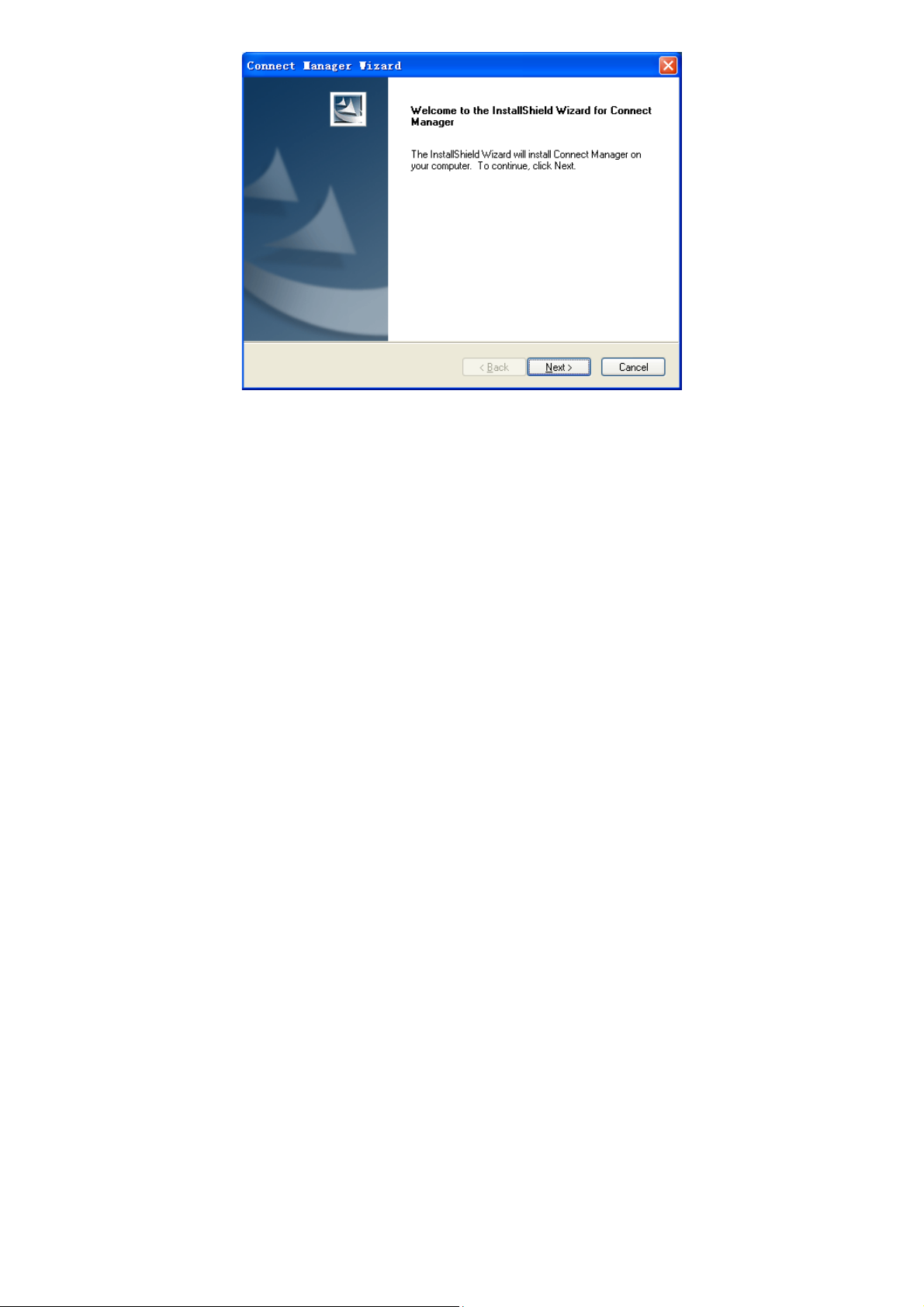
2.1 Install Software
1. It is strongly recommended that you exit all other Windows programs, and
then click the Next button.
3
Page 4
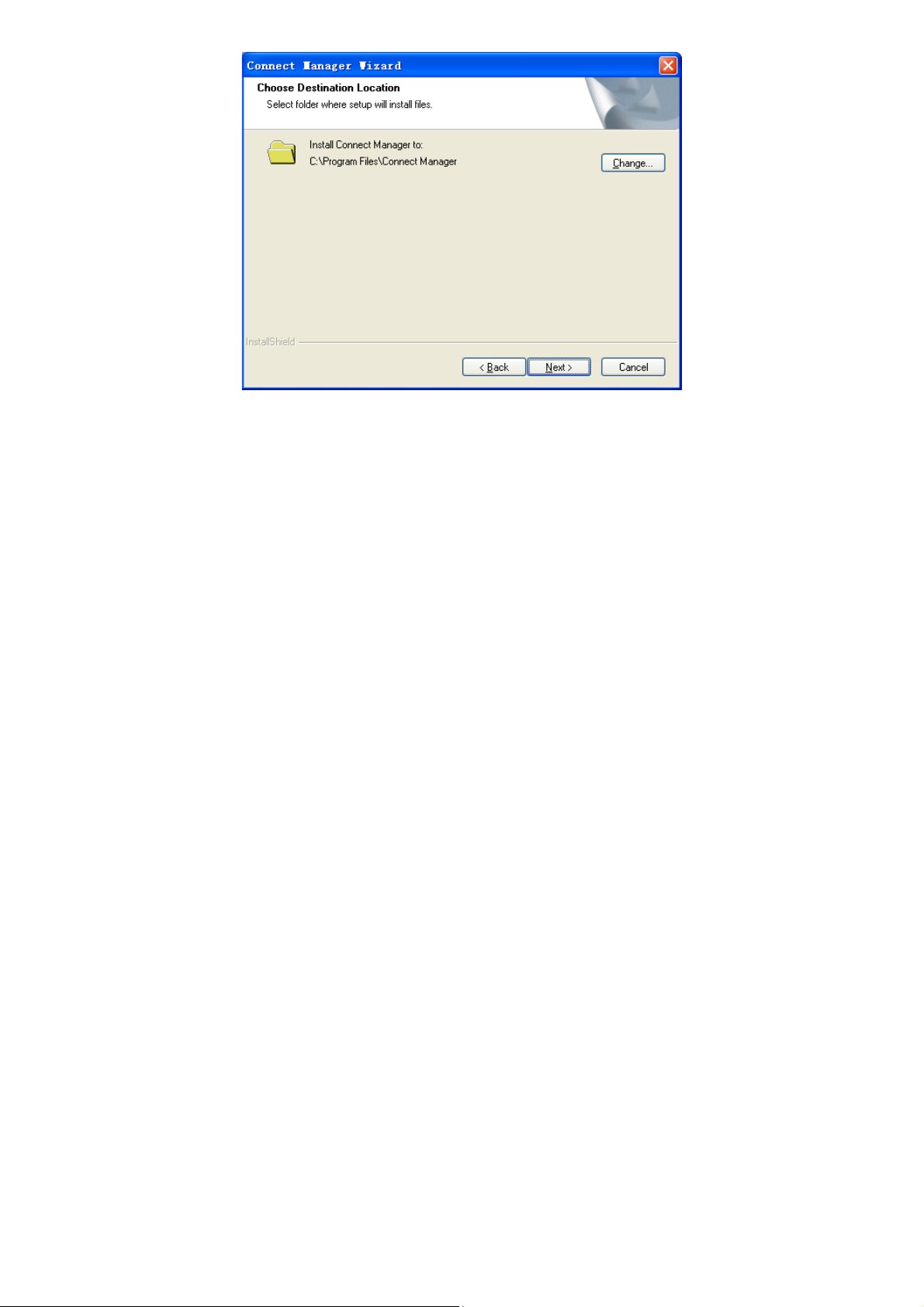
2. Select the folder that you want to install the software by pressing the Change
button, and then click the Next button.
4
Page 5
3. The system shows the installation progress, wait a minute and click the Finish
button to complete the installation.
5
Page 6

Note: After the software is installed, pull out the modem before restarting the
computer to avoid damages to your modem. If you have problems with the
installation steps above, please contact your service provider or ZTE.
After the installation, select Start > Programs > Connect Manager. You can
find Connect Manager and Uninstall. There will be a shortcut icon on the
desktop just as follows.
2.2 Run the Application Software
After the modem is correctly connected to the computer, click Start >
Programs > Connect Manager > Connect Manager on the computer to run the
application software.
6
Page 7

You can also launch the application software by double-clicking the shortcut icon
shown above.
After the modem is initialized, the main interface of the connection manager
appears. The standby icon appearing in the taskbar indicates the modem
working normally.
7
Page 8
3 Functions & Operation
3.1 Interface introduction
3.1.1 Main Interface
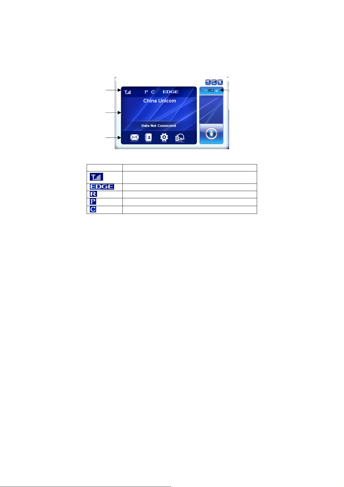
The following picture is the starting screen of the software. The whole interface is
divided into four parts. Related functions can be executed by operation in the
related areas.
System
information
area
Internet
information
area
Function
button area
Main menu
button area
System information area
Icons in this area show the system status and different kinds of tips.
Icon Explanation
Indication of signal strength, which is divided into 6 stages from
none to the strongest.
Indication of current network type.
Roaming.
Packet switched
Circuit switched
Internet information area
This area shows the name of the current service provider, device condition and
connection information.
8
Page 9

Function button area
There are five function button icons.
SMS: Send, read and manage SMS.
Phonebook: Manage contact information.
Settings: Setting options for the device.
Data records: Show connection information.
Connect: Connect to the Internet.
Main menu button area
Click the icon to popup the following menu:
Diagnostics: View Hardware information, Operational information and Network
Settings.
Help: Show the help document.
Language: Change the language of the software interface.
Exit: Close the software.
3.2 Description of Mini Icons
Click the minimize button and the software will minimize as an icon on the
taskbar. This will not influence data transfer or sending and receiving of SMS.
Double click the icon on the taskbar to restore the window.
Taskbar icons description
The device is ready to connect to the Internet.
The device is connected to the Internet.
The uses of taskbar icons
Click the taskbar icon , the following menu will appear. Please refer to Main
menu button area in Section 3.1.
9
Page 10

Diagnostics: View Hardware information, Operational information and Network
Settings.
Help: Show the help document.
Language: Change the language of the software interface.
Exit: Close the software.
3.3 Connecting to the Internet
With the help of your device, you can access the Internet and browse web pages
while still be able to send and receive SMS.
Click the Connect button
automatically. You can click Cancel button
. The system will search for available networks
to cancel connection.
When connected, connection duration and data record will be shown in the
10
Page 11

Internet information area. Then you can access the Internet and receive email
etc, through the network.
When the connection is established, the “Connect” button changes into the
Disconnect button
. Click it to disconnect from the Internet.
3.4 SMS
Note: To make sure that the SMS can be used properly, please setup the
correct SMS center number. Refer to section 3.6.4 SMS Settings.
Click the SMS icon
of SMS in your PC (LOCAL) and (U)SIM card. Click Inbox, Sentbox, Draftbox,
Important, Deleted, Report to enter relative interface.
to switch to the SMS interface, which shows the number
11
Page 12

Inbox: Save the received messages.
Sentbox: Save the sent messages.
Draftbox: Save the draft messages.
Important: Save the important messages that you have moved from other
folders.
Deleted: Save the deleted messages.
Report: Save the message reports.
3.4.1 Check SMS
When an incoming message is received, a pop-up dialog box will appear above
the taskbar. Click the Inbox button to check the new message.
Click other buttons in the SMS window to view the messages in each folder.
Select a message to read its full content below the message list.
3.4.2 Create a new message
Click the New button to open a new dialog box and input the recipient’s number
and message content.
12
Page 13

The recipient’s number can be input directly or by clicking the To button and
selecting contacts from the Phonebook.
To send a message to multiple recipients, please separate each recipient with
“;”.
The SMS content can include 160 individual English characters (including
English symbols). The total characters and the number of messages need to be
sent are shown in the dialog box.
Click Send and then click OK to send the short message
Sending SMS while browsing the web:
If your network supports, you can send short messages when surfing on the
Internet. Click SMS button, enter the SMS interface to write and send short
messages normally.
3.4.3 The SMS box operating guide
Enter Inbox/Sentbox/Draftbox/Important to execute the following by clicking
on each button or right-clicking on a message:
Reply: Reply short messages to the sender (available only in “Inbox”).
Forward: Forward a short message to other recipients (available only in
“Inbox”).
Move: Change the location where selected messages are stored (LOCAL or
USIM/SIM card). By default, the messages the modem received are saved on
LOCAL (computer).
Delete: Delete the selected short messages.
13
Page 14

Save Number / Save Num: Save the sender’s number to Phonebook.
Send: Send selected messages in Sentbox/Draftbox.
Edit: Edit selected message in “Draftbox”.
Export/Import: Export the SMS to CSV or import SMS from CSV.
Save to Important: Move the SMS to Important folder.
Revert: Move the SMS from Important or Deleted folder back to other folders.
If you want to select several messages, hold “Ctrl” or “Shift” key and left-click on
the items.
New messages can not be received when the (U)SIM card is full (different
USIM/SIM cards have different capacities). The system will indicate that the
inbox is full and prompt you to clear the “Inbox” of USIM/SIM card.
3.5 Phonebook
Click Phonebook icon to enter Phonebook interface. Contact information
can be saved either on your PC or the SIM/USIM card. For each contact record
on the PC, the information includes name, mobile phone number, home phone
number, office phone number, emails and the group to which it belongs. For
each contact record on the SIM/USIM card, the information only includes name
and mobile phone number.
3.5.1 Create a new contact
1. Click “New” to add a new contact;
14
Page 15

2. Select contact type (“PC” or “(U)SIM”) and input the information. Then click
“OK”.
3.5.2 Modify contacts
1. Select a contact and click Edit.
2. Edit the contact information and click OK.
3.5.3 Delete contacts
1. Select one or more contacts and then click Delete.
2. Click OK to confirm.
3.5.4 Send SMS to contacts
1. Right click the selected contacts and select SMS.
2. Input message content in the new window and click Send.
3.5.5 Search for a contact
1. Enter the keyword in the search box.
15
Page 16

2. Click Search to search for matching results, which will be displayed in the
contacts list.
3.5.6 Other buttons Description
If any contact is selected, you can execute any of the following by clicking on the
corresponding button.
View: View the selected contact’s information.
Move: Change the location (PC or (U)SIM) where selected contacts information
is stored.
Right click on the contacts and you can create new contacts, view, edit,
copy-and-paste, move, delete, export, or import selected contacts.
3.6 Settings
Click Settings icon to switch to the settings interface.
Note: All the necessary settings have been preset by default. There is no need
to change such settings. If you want to change these settings, please consult
your service provider.
3.6.1 Connection
16
Page 17

1 Button description
Add: Add new configuration files.
View/Edit: View/edit the selected configuration file. The default configuration
can only be viewed, not edited.
Delete: Delete the selected configuration files.
2 Add new Configuration file
Click the Add button to add new connection information to the system.
There are two parts of configuration information: Common and Advance.
The Common information includes Config File, APN and User name.
The Advance information includes DNS, PDP server, Authentication mode
and PDP Type. Please consult your network service provider for all above
information. The configuration information may vary as the service provider and
network type differ.
3.6.2 Selection
Automatic: The system selects the network automatically.
Manual: Manually select the network.
When Manual is selected, click the Search button to search for available
networks. Select the proper network from the search results and click Apply to
confirm.
3.6.3 Preference
Automatic: The system selects available network automatically.
UMTS/HSPA Only: The system will only select UMTS or HSPA networks.
GPRS/EDGE Only: The system will only select GPRS or EDGE networks.
17
Page 18

3.6.4 SMS Settings
SMS center number: Set the message center number. You can use the default
number preset by your service provider. The correct SMS center number must
be input in order to use the SMS properly. If you want to edit it, please consult
with your service provider for more information.
SMS validity: Set the time limit for saving SMS in the network side. (This
function needs network support.) You can select 12 hours, A day, A week or
The longest period. The default setting is the longest period permitted by the
network.
Default save location of received SMS: Select PC to save the received SMS in
your PC; select (U)SIM card to save it in SIM/USIM card.
State report: Enable state report to receive notification when the message is
sent successfully.
18
Page 19

3.6.5 Sounds
You can set Network connect alert, Network disconnect alert and SMS alert.
These alerts will sound on the PC side. The audio file supports MP3, WAV, MID
and WMA formats. Select Mute to mute corresponding alert.
3.6.6 Security settings
19
Page 20

Enable or disable PIN code protection. Click the Change button to change the
PIN code. Click the Apply button and input the PIN code to apply the security
changes.
Note: If the PIN code protection is enabled, you need to enter the PIN code
every time you start to use the modem.
3.6.7 System
Auto start when device is available: The software will start automatically when
the device is available.
Auto connect: Automatically connect to the Internet when the software is ready.
User data: Automatically save user data when exit the software.
3.6.8 Update settings
You can check for update automatically, or manually by clicking Update now.
20
Page 21

3.7 Data records
Click the Data records icon to check the log of Internet connection history.
In the Transfer Data tab, you can check the real-time upload/download speed,
upload/download data and transfer time. You can also check the
upload/download data and duration in one day, one month and one year.
In the Data records tab, select start date From and end date To on top to view
the record of data exchange in the given period.
Select a record and click the Delete button to delete the record. Click Clear to
delete all the records in the list.
Note: Data usage is approximate only. Please contact your operator for actual
usage.
3.8 Help
Click , and then select “Help” to open the help interface.
21
Page 22

22
Page 23

4 FAQ & Answers
When you meet the following problems in service, please refer to the following
answers to solve it. If the problems still exist, please contact with your suppliers.
Problem Description Possible Causes Problem Solving
After restarting the
computer, there is no
signal indicated.
Sent Message failure. 1. The SMS center
Date connection
failed.
1. You are in the place
where there is no
network coverage. Such
places include
underground parking
garages, tunnels, and
some remote rural areas.
2. The (U)SIM card isn't
inserted properly.
3. Your notebook is
positioned in such a way
as that adversely affects
the devices signal
reception.
number is incorrect.
2. The network is busy
or you are in an area
with no signal.
1. You are in the place
where there is no GSM/
GPRS/ EDGE/ WCDMA/
HSPA network coverage.
2. The network is busy. 2. Try later.
23
1. Change location to
find a good where
having signal.
2. Remove and reinsert
the (U)SIM card
correctly.
3. Adjust the angle /
position of your
notebook or its proximity
to other electronic
devices.
1. The module is
preconfigured so it is
unlikely that it will need
changing. However if it is
missing or incorrect
contact your operator.
2. Try later or move to an
area with a stronger
signal.
1. Move to an area with
good signal.
Page 24

Problem Description Possible Causes Problem Solving
3. Check the APN in the
user configuration file in
the “Network settings”.
4. Local network access
or the target server
maybe experiencing
problems. Retry data
request.
5. Reselect the network
type according to the
type of the (U)SIM card.
1. Check that the APN in
the configuration files is
correct.
2. Upgrade to the new
version or reinstall the IE
browser.
3. Use the professional
anti-virus software to
check and remove the
virus.
4. This happens when
you are changing any
preset operator value in
the setting section.
Check the entry and
enter the correct APN
from your operator.
Connected to the
Internet, but it cannot
open any website
page.
3. The APN in the user
configuration file is
incorrect.
4. The module data is
corrupted.
5. The network type has
been selected manually,
but is incorrect.
1. After connection, you
are unable to open web
pages.
2. IE browser is causing
problems.
3. Your operating system
maybe infected by a
virus. Worm Blaster for
example can affect
upload and downloaded
data flow, resulting in an
inability to access a
website.
4. You have connected
to an APN which cannot
connect to the Internet.
24
Page 25

5 Warning and notice
5.1 To the owner
• Some electronic devices are susceptible to electromagnetic interference sent
by the module if inadequately shielded, such as the electronic system of
vehicles. Please consult the manufacturer of the device before using the
device if necessary.
• Operating of laptop and desktop PCs with the module may interfere with
medical devices like hearing aids and pacemakers. Please always keep them
more than 20 centimeters away from such medical devices when they are
turned on. Turn the computer off if necessary. Consult a physician or the
manufacturer of the medical device before using the computer.
• Be aware of the usage limitation when using the module at places such as oil
warehouses or chemical factories, where there are explosive gases or
explosive products being processed. Turn off your device if required.
• The use of electronic transmitting devices is forbidden in aircrafts, at petrol
stations and in hospitals. Please observe and obey all warning signs and
switch off your devices in these conditions.
• Do not touch the metallic parts of the module so as to avoid a burn, when the
modem is working.
5.2 Using your USB Modem
• Avoid using the module near or inside metallic structures or establishments
that can emit electromagnetic waves. Otherwise it may influence signal
reception.
• The module is not waterproof. Please keep it dry and store in a shady and
cool place.
• Do not use the module immediately after a sudden temperature change.
• Handle the module carefully. Do not drop, bend or strike it. Otherwise the
module will be damaged.
• No dismantling by non-professionals and only qualified technicians can
undertake repair work.
• Operating temperature range of -10℃ ~ +60℃ and humidity range of 5% ~
95% are recommended.
25
 Loading...