

Page 1

Draft V e rsion
X6 Wireless-G
DSL Modem
Router
X6 Model 5590 User’s Manual
Zoom Telephonics
Issue 1
02012005
Page 2

Compliance Statements and Notices to User
Federal Communications Commission Compliance Notices
This device complies with 15 of the FCC Rules. Operation is subject to the
following two conditions:(1) this device may not cause harmful interference, and
(2) this device must accept any interference received, including interference that
may cause undesired operation.
To ensure continued compliance, use only shielded interface cables when
connecting to the computer or peripheral devices.
Federal Communication Commission (FCC) Statement:
NOTE: This equipment has been tested and found to comply with the limits for
a Class B digital device, pursuant to part 15 of the FCC Rules. These limits are
designed to provide reasonable protection against harmful interference in a
residential installation.
This equipment generates, uses and can radiate radio frequency energy and, if
not installed and used in accordance with the instructions, may cause harmful
interference to radio communications. However, there is no guarantee that
interference will not occur in a particular installation. If this equipment does
cause harmful interference to radio or television reception, which can be
determined by turning the equipment off and on, the user is encouraged to try
to correct the interference by one or more of the following measures:
Reorient or relocate the receiving antenna.
Increase the separation between the equipment and receiver.
Connect the equipment into an outlet on a circuit different from that to which
the receiver is connected.
Consult the dealer or an experienced radio/ TV technician for help.
Changes or modifications not expressly approved by the party
responsible for compliance could void the user’s authority to operate the
equipment.
The antenna(s) used for this transmitter must not be co-located or
operating in conjunction with any other antenna or transmitter.
The manufacture is not responsible for any radio or TV interference
caused by unauthorized modifications to this equipment. Such
modifications could void the user’s authority to operate the equipment.
This equipment complies with FCC radiation exposure limits set forth for an uncontrolled environment.
In order to avoid the possibility of exceeding the FCC radio frequency exposure limits, human proximity
to the antenna shall not be less than 20cm (8 inches) during normal operation.
Page 3

DSL Modem User’s Guide
Table of Contents
1 Introductio n.............. .... .... ..... .... .... ..... ...... ..... .... .10
Features................................................................ ..............10
Device Requirements.........................................................10
Using this Document.................................. ...................... ...12
Notational conventions................................................12
Typographical conventions..........................................12
Special messages........................................................12
Getting Support........................................................... ........12
2 Getting to k no w the d evi ce............................... .13
Parts Check...................................................................... ...13
Front Panel..........................................................................14
Rear Panel..........................................................................15
3 Connecting your device.....................................16
Connecting the Hardware...................................................16
Step 1. Connect the DSL cable and optional
telephone..................................................................17
Step 2. Connect the Ethernet cable............................18
Step 3. Attach the power connect or............................18
Step 4. Configure your Ethernet PCs..........................18
Step 5. Install USB software and connect the
USB cable.................................................................18
Step 6. Install Wireless card and connect
Wireless PCs............................................................18
Next step......................................................................18
4 Getting Sta r te d wi th th e W e b pa g e s.................19
Accessing the Web pages..................................................19
Web page menu overview..................................................20
Commonly used buttons.....................................................21
Help information.................................................... ..............22
Testing your Setup..............................................................22
Default device settings........................................................23
Current Status.............................................. .....25
5
Internet access settings......................................................25
About Productname...........................................................26
6 Firmware Update...............................................27
3
Page 4

DSL Modem User’s Guide
About firmware versions.....................................................27
Checking for firmware updates...........................................27
Updating your firmware......................................... ..............29
Manually updating firmware ...............................................30
7 Health Chec k.......................... ...... ....... ......... .....32
Running the Health Check.................................................32
DSL Status page.................................................................34
8 Help............................. .... ..... .... .... ..... .... .... ..... ...40
Using the Help page...........................................................40
About the Online User Guide.............................................41
Addressing................................................... .... .42
9
Changing the LAN IP address and subnet mask..............42
Wireless Net wo rk................................ ...... ........44
10
Wireless Network First Time Settings Wiz ard................. ...45
Setting the Country......................................................45
Select your Wireless Network Type............................45
Set the Wireless Network Name.................................46
Select a Channel..........................................................47
Configure Wireless Network Security ............ ..............48
Configuring 64bit or 128bit encryption ........................49
Configuring WPA security......................................... ...50
Configure Wireless Address Authentication...............50
Configuring the wireless PC blacklist..........................51
Configuring the wireless PC whitelist..........................53
Confirm Wireless network changes ............................54
Wireless Network General Settings...................................55
Enabling/disabling wireless networking............... ........56
Displaying details of Wireless PCs..............................56
11 Advanced Securi ty............................ ......... .......58
Configuring NAT Security...................................................58
Assigning PC Names..........................................................59
Deleting PC Names.....................................................61
Configuring Internet applications........................................61
Enabling Internet applications.....................................61
Disabling Internet applicatio ns....................... ..............62
Configuring custom applica tions........................................63
4
Page 5

DSL Modem User’s Guide
Creating custom applications......................................63
Deleting custom applications.......................................65
12 Internet A cc es s..... ..... .... .... ..... .... ..... .... .... ....... ...66
Types of Internet Access....................................................66
Configuring Automatic Internet Access..............................67
Configuring your PPP DSL connection..............................68
Enabling MAC spoofing...............................................71
Editing your existing MAC spoofing settings...............72
Configuring your DHCP DSL connection...........................73
Configuring your Internet Access ma nuall y.......................74
13
Reset to De faul ts........................ ....... ...... ....... ...80
14
Password.......... .... ..... .... .... ....... .... ..... .... .... ..... ...77
Setting your username and password...............................77
Disabling password protecti on....................................79
Resetting to Defaults.................. ................ ................. ........80
A Configurin g y ou r Co mp u ters.......................... ...82
Configuring Ethernet PCs...................................................82
Before you begin..........................................................82
Windows® XP PCs......................................................82
Windows 2000 PCs.....................................................84
Windows Me PCs........................................................85
Windows 95, 98 PCs...................................................86
Windows NT 4.0 workstations.....................................86
Assigning stat ic Int ern et inf orm atio n t o yo ur
PCs...........................................................................88
Configuring a USB PC........................................................89
Connecting a computer to the USB port.....................89
Part 1. Installing the USB Driver..................................89
Part 2. Configuring IP properties on the USB
PC.......................................................................... ...95
Configuring Wireless PCs..................................... ..............96
Siting the wireless PCs................................................96
Wireless PC cards and drivers....................................96
Configuring PC access to y our Wirel ess d evice.........96
IP Addresses, Network Masks, and
B
Subnets ..........................................................99
IP Addresses.......................................................................99
5
Page 6

DSL Modem User’s Guide
Structure of an IP address...........................................99
Network classes.........................................................100
Subnet masks...................................................................100
C Troubleshooting ..............................................102
Troubleshooting Suggestions...........................................102
Diagnosing Problem using IP Utilities..............................104
ping............................................................ .................104
nslookup.....................................................................104
D Advanced DSL po rt attri but es.........................106
Glossary................................... .... ..... .... ..... .... .111
E
6
Page 7

DSL Modem User’s Guide
Table of Figures
Figure 1: DSL Modem Package Contents..............................................................13
Figure 2: Front Panel and LEDs..............................................................................14
Figure 3: Rear Panel Connections............................................................ ..............15
Figure 4:
Figure 5:
Figure 6:
Figure 7:
Figure 8:
Figure 9:
Figure 10: No updates available page......................................................................28
Figure 11: Update Available page.............................................................................29
Figure 12: Downloading and installing update… page.............................................30
Figure 13: Update Installed page..............................................................................30
Figure 14: Restarting page........................................................................................30
Figure 15: Manual Update Installation section....................................................... ...31
Overview of Hardware Connect ions........................................................17
Login screen ..................................................................................... ........19
The Welcome page..................................................................................20
Current Status page.................................................................................25
Firmware Update page............................................................................28
Checking for Updates… page ......................................................... ........28
Figure 16: Health Check page..................................................... ................ ..............32
Figure 17: Health Check: Running page...................................................................32
Figure 18: Health Check: Complete with fail ures pag e............................................33
Figure 19: Health Check: Complete with no fa ilures page.......................................34
Figure 20: Health Check page..................................................... ................ ..............34
Figure 21: Health Check: DSL Status page..............................................................35
Figure 22: DSL Port Basic Configuration page................................................. ........36
Figure 23: Port A1 Advanced Configuration page (part 1).......................................37
Figure 24: Port A1 Advanced Configuration page (part 2).......................................39
Figure 25: Help page ………………………………………………………….............40
Figure 26: Help – Close link............................. ................. ................ ...................... ...41
Figure 27: Addressing page......................................................................................42
Figure 28: Addressing: Setup page.................................. ................ ................. ........42
Figure 29: Addressing: Confirm page.......................................................................43
Figure 30: Wireless Network page......................................................................... ...44
Figure 31: Wireless Network: Set Country pag e......................................................45
Figure 32: Wireless Network: Wireless Netw ork Type Selecti on page....................46
Figure 33: Wireless Network: Basic page.................................................................46
Figure 34: Wireless Network: Channel Selection page............................................47
7
Page 8

DSL Modem User’s Guide
Figure 35: Wireless Network: Channel Selection (manual) p age...........................48
Figure 36: Wireless Network: Security page.......................................................... ...48
Figure 37: Wireless Network: 128bit Network Key p age..........................................49
Figure 38: Wireless Network: Wi-Fi Protecte d Access page ................. ................ ...50
Figure 39: Wireless Network: Address Authentic atio n page....................................51
Figure 40: Wireless Network: Address Authe nticati on (blac klist) pa ge...................52
Figure 41: Wireless Network: Address Authe nticati on (blac klist) pa ge...................52
Figure 42: Wireless Network: Address Authe nticati on (blac klist) pa ge...................52
Figure 43: Wireless Network: Address Authe nticati on (w hitelist) pa ge...................53
Figure 44: Wireless Network: Address Authe nticati on (w hitelist) pa ge...................53
Figure 45: Wireless Network: Address Authe nticati on (w hitelist
configuration) page.......................................................... ...................... ...54
Figure 46: Wireless Network: Confirm page.............................................................54
Figure 47: Wireless Network: General Sett ings sec ti on...........................................55
Figure 48: Wireless Network: Enable/Disable page.................................................56
Figure 49: Wireless Network: Connected Wireless PCs page.................................56
Figure 50: Advanced Security page............................................................ ..............60
Figure 51: Advanced Security: PC Names page......................................................60
Figure 52: Advanced Security: Add PC Name page................................................60
Figure 53: Advanced Security: Add PC Name page................................................61
Figure 54: Advanced Security: Enabled Applications page.....................................61
Figure 55: Advanced Security: Enable Application page.........................................62
Figure 56: Advanced Security: Confirm Application page........................................62
Figure 57: Advanced Security: Disable Application page........................................63
Figure 58: Advanced Security: Custom Applicatio ns pa ge......................................63
Figure 59: Advanced Security: Create Applicatio n page..........................................64
Figure 60: Advanced Security: Add Port pa ge...... ................ ................. ........... ........64
Figure 61: Advanced Security: Confirm Custom Applicati on page..........................65
Figure 62: Advanced Security: Disable Applicatio n..................................................65
Figure 63: Internet Access page...............................................................................67
Figure 64: Internet Access: Types of Access page..................................................67
Figure 65: Internet Access: Auto page......................................................................67
Figure 66: Internet Access: Searching page.......................................................... ...68
Figure 67: Internet Access: PPP Setup page...........................................................68
Figure 68: Internet Access: Search Complete page.............................................. ...68
Figure 69: Internet Access page...............................................................................69
Figure 70: Internet Access: Types of Access page..................................................69
8
Page 9

DSL Modem User’s Guide
Figure 71: Internet Access: PPPoA page.................................................................70
Figure 72: Internet Access: VPI and VCI Setup p age..............................................70
Figure 73: Internet Access: Confirm page................................................................70
Figure 74: Internet Access: PPPoE page.................................................................71
Figure 75: Internet Access: MAC Spoofing page.....................................................72
Figure 76: Internet Access: MAC Spoofing Setu p page........................ ................ ...72
Figure 77: Internet Access: MAC Spoofing C onfirm................................... ..............72
Figure 78: Internet Access page...............................................................................73
Figure 79: Internet Access: Types of Access page..................................................73
Figure 80: Internet Access: VPI and VCI Setup p age..............................................74
Figure 81: Internet Access: Confirm page................................................................74
Figure 82: Internet Access page...............................................................................75
Figure 83: Internet Access: Types of Access page..................................................75
Figure 84: Internet Access: Manual Setup p age......................................................75
Figure 85: Internet Access: VPI and VCI Setup p age..............................................76
Figure 86: Internet Access: Confirm page................................................................76
Figure 87: Password page........................................................... ........................... ...77
Figure 88: Password: Enable/Disable page................................................ ..............78
Figure 89: Password: Setup page.............................................................................78
Figure 90: Password: Confirm page............................................ ................ ..............78
Figure 91: Reset to Defaults page............................................... ................ ..............80
Figure 92: Resetting to Defaults…............................................................................80
Figure 93: USB Setup Wizard: Installi ng Window....................................................90
Figure 94: Prompt for USB Cable Plug-in.................................................................90
Figure 95: USB Cable Connectors............................................................................91
Figure 96: Windows XP Driver Installation............................................. ...................92
Figure 97: Windows XP driver ‘Remote Network D evice foun d’..............................92
Figure 98: Windows XP driver ‘Not XP com patibl e’ warning ................. ................ ...93
Figure 99: Windows XP driver Hardware Wizard.....................................................93
Figure 100: Windows XP Device Properties for the i nstall ed device.........................94
Figure 101: Using the ping Utility...............................................................................104
Figure 102: Using the nslookup Utility.......................................................................105
9
Page 10

錯誤! 尚未定義樣式。
User’s Guide
1 Introduction
錯誤! 尚未定義樣式。
Congratulations on becoming the owner of the Zoom
Telephonics 錯誤!
access the Internet using your high-speed DSL connection.
尚未定義樣式。
. You will now be able to
This User Guide will show you how to connect you r 錯誤!
義樣式。
get the most out of your new product.
DSL Modem, and how to customize its configuration to
尚未定
Features
The list below contains the main features of the device and may
be useful to users with knowledge of networking protocols. If you
are not an experienced user, the chapters throughout this guide
will provide you with enough information to get th e most out of
your device.
Features include:
•
Internal DSL modem for high-speed Internet access
•
10/100Base-T Ethernet router to provide Internet
connectivity to all computers on your LAN
•
USB port for connecting a USB-enabled PC
•
Wireless access via a wireless network card and w ireless
security features
• Network address translation (NAT) functions to provide
security for your LAN
• Network configuration through DHCP Server an d DHCP
Client
• Services including IP route and DNS configuration, RIP, and
IP and DSL performance monitoring
•
Configuration program you access via a web browser
[CT3]
Device Requirements
In order to use the 錯誤! 尚未定義樣式。, you must have the
following:
• DSL service up and running on your telephone line
• Instruc tion s fr om y our I SP on wh at type of Int er net ac ce ss
you will be using, and the addresses nee ded to s et up
access
•
One or more computers each containing an Ethernet card
(10Base-T/100Base-T network interface card (NIC)) and/or a
single computer with a USB port
10
Page 11

錯誤! 尚未定義樣式。
User’s Guide
Note
錯誤! 尚未定義樣式。
•
For system c onfi gur atio n us ing t h e sup plie d w eb- bas ed
program: a web browser such as Internet Explorer v4 or later,
or Netscape v4 or later. Note that version 4 of each browser
is the minimum version requirements – for optimum display
quality, use Internet Explorer v5, or Netscape v6.1.
You do not need to use a hub or switch in order to connect more
than one Ethernet PC to your device. Instead, you can connect
up to four Ethernet PCs directly to your device using the ports
labeled Ethernet 2 on the rear panel.
11
Page 12
錯誤! 尚未定義樣式。
User’s Guide
錯誤! 尚未定義樣式。
Using this Document
Notational conventions
• Acronyms are defined the first time they appear in text and in
the glossary.
• For brevity, the 錯誤! 尚未定義樣式。 is referred to as “the
device”.
• The term LAN refe rs to a gr oup of Ethernet-connected
computers at one site.
• The term WLAN refers to a group of Wireless-connected
computers at one site.
Typographical conventions
• Italic text is used for items you select from menus and drop-
down lists and the names of displayed web pages.
• Bold text is used for text strings that you type when
prompted by the program, and to emphasize important
points.
Special messages
This document uses the following icons to call your attention to
specific instructions or explanations.
Note
Provides clarifying or non-essential information on the c urrent
topic.
Definition
Explains terms or acronyms that may be unfamiliar to many
readers. These te rms are als o in clud ed i n the Glos sa ry.
Provides messages of high importance, including messages
relating to personal safety or system integrity.
WARNING
Getting Support
<Your text>
12
Page 13

錯誤! 尚未定義樣式。
User’s Guide
2 Getting to know the device
Parts Check
In addition to this document, your package should arrive
containing the following:
• 錯誤! 尚未定義樣式。 DSL Modem
•
Power adapter and power cord
•
USB cable
•
Ethernet cable
•
Standard phone/DSL line cable
錯誤! 尚未定義樣式。
[Insert a photograph of the contents of your product kit.]
Figure 1: DSL Modem Package Contents
13
Page 14

錯誤! 尚未定義樣式。
User’s Guide
錯誤! 尚未定義樣式。
Front Panel
The front panel contains a Restore Defaults butto n, a wireless
network card slot and lights called LEDs that indicate the status
of the unit.
[Insert photo of your own front-panel with LEDs]
Figure 2: Front Panel and LEDs
Label Color Function
Restore
Defaults
PCMCIA
802.11b
Power green
USB
Link/Act
W-LAN
Link/Act
Internet orange On: Valid IP address obtained
DSL
HS
DSL
Link/Act
LAN
10/100
LAN
Link/Act
N/A
N/A
green
green On: Wireless LAN link established
green On: High Speed (16 Mbit) rate established
green
green
green
Pressing this button restores the factory default
configuration on your device
Allows you to insert a Wire less netwo rk ca rd
that enables a Wireless LAN to a ttach to y o ur
device
On: device is powered on
Off: device is powered off
On: USB link is established
Off: No USB link
Blink: Data being transmi tted
Off: No Wireless LAN link
Blink: Data being transmi tted
Off: No IP address obtained
Blink: Valid IP packet being transferred
Off: 8 Mbit rate established
On: DSL link reaches showtime, which mean s
that your device has successfully conne cted to
your ISP’s DSL network.
Off: DSL link not in show time , your device has
not successfully connected to y our ISP’s DSL
network.
Blink: Data being transmi tted
On: Fast (100BaseT) E therne t link es tabl ished
and active
Off: 10BaseT Ethernet link established and
active
On: LAN link established and active
Off: No LAN link
The initial Argon 4x1 Customer Evaluation Board only supports
the green Power LED (D1705 – TOP). This table is provided as
an example of the status LEDs that you may wish to create. You
must edit this table and the table in Testing your Setup on page
22 to reflect your own LED configuration.
[CT9]
14
Page 15

錯誤! 尚未定義樣式。
User’s Guide
錯誤! 尚未定義樣式。
Rear Panel
The rear panel contai ns the po rts for th e unit's dat a and po wer
connections.
[Insert photo of your own rear-panel with connectors]
Figure 3: Rear Panel Connections
Label Function
Power Connects to the supplied power cable
USB Connects to the USB port on your PC
Ethernet 1
Ethernet 2
DSL
V.9x Provides an optional connection to your telephone
Connects the device via Ethernet to yo ur LAN’s hub or
switch (disabled)
Connects the device via Ethernet to up to four PCs on
your LAN (default)
Connects the device to a teleph one port in the wa ll o f
your home/office for D SL co m munication
15
Page 16

錯誤! 尚未定義樣式。
User’s Guide
3 Connecting your device
This chapter provides basic instructions for connecting the
尚未定義樣式。
You also need to configure Internet properties on your
computer(s) and install the s oftware f or using a comp uter
attached to the USB port. For m ore deta ils, see the fo llow ing
sections:
•
Configuring Ethernet PCs on page 82
•
Configuring a USB PC on page 89
•
Configuring Wireless PCs on page 96
This chapter assumes that you have alre ady establis hed a DSL
service with your Internet service pr ovider (ISP ). These
instructions provide a basic configuration that s hould be
compatible with your home or sm all office network set up. Refer
to the subsequent chapters for additi onal conf igurati on
instructions.
錯誤! 尚未定義樣式。
to a computer or LAN and to the Internet.
錯誤
!
Connecting the Hardware
In Part 1, you connect the device to the wall phone port, the
power outlet, and your computer or netw ork.
WARNING
Before you begin, turn th e powe r off for all d evices.
include your computer(s), your LAN hub/sw itch (if applicable ),
and the
錯誤! 尚未定義樣式。
.
These
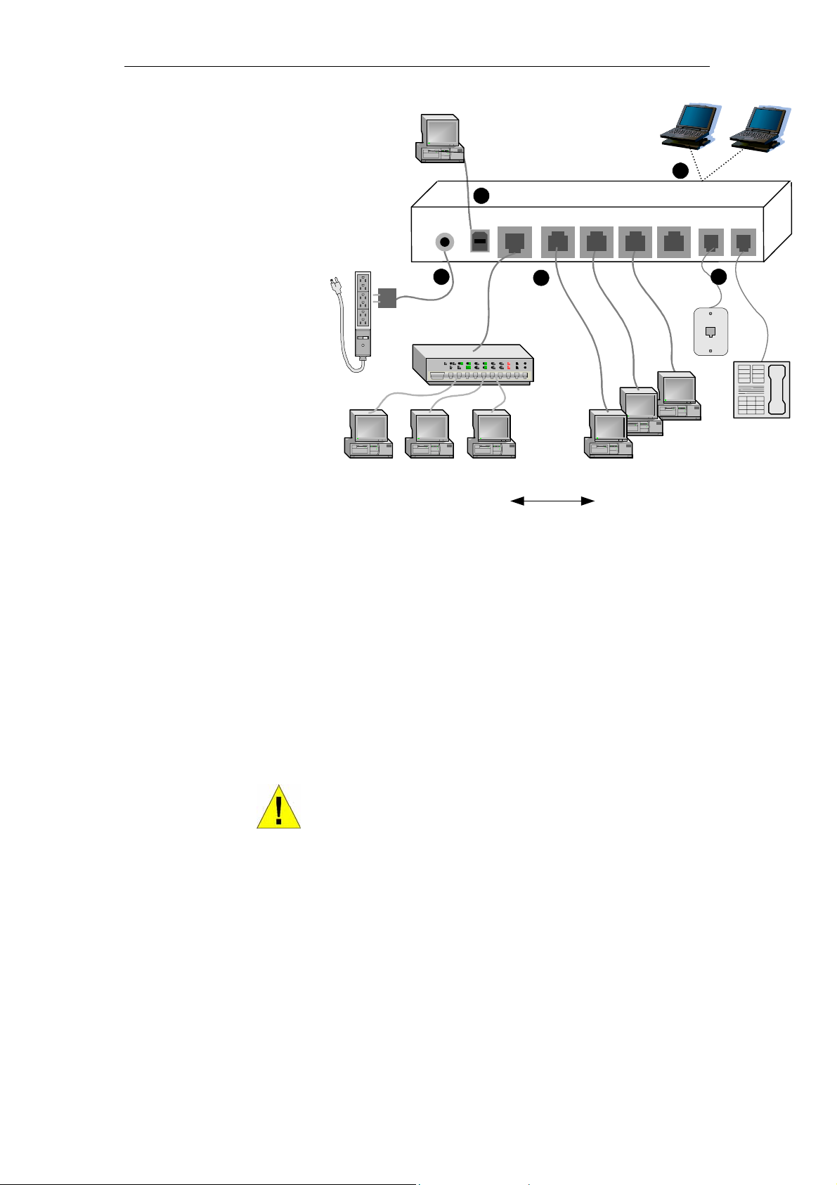
The diagram below illustrates the hardware connections. The
layout of the ports on your device may v ary from the layout
shown. Refer to the steps that follow for specific inst ructions.
16
Page 17
錯誤! 尚未定義樣式。
x
A
User’s Guide
錯誤! 尚未定義樣式。
Stand-alone PC
4
Power
USB
3
C adapter
Networked Computers
To a hub
Ethernet 1
2
Hub/switch
(for local area
network)
OR
Wireless PCs
ADSL/Ethernet Bridge/Router
Ethernet 2
To up to 4 stand-alone PCs
5
DSL
V.9
1
Wall
phone
port
Telephone
(optional)
Figure 4: Overview of Hardware Connections
WARNING
Step 1. Connect the DSL cable and optional t elephone
Connect one end of the provided phone cable to the port
labeled DSL on the rear panel of the device. Connect the othe r
end to your wall phone port.
You can attach a telephone line t o the dev ice. This is h elpful
when the DSL line uses the only co nvenie nt wall ph one port. If
desired, connect the telephone cable to the port labeled
[CT15]
V.9x
.
Although you use the same type of c able, The DS L and V.9x
ports are
through the V.9x port.
not
interchangeable. Do not route the DSL connection
17
Page 18

錯誤! 尚未定義樣式。
User’s Guide
錯誤! 尚未定義樣式。
Step 2. Connect the Ethernet cable
must
You
options:
delete one of the following Ethernet connection
[CT17]
Connect either a LAN hub or a single Ethernet computer directly
to the device via Ethernet cable.
Connect either a LAN hub or up to four single Ethernet
computers directly to the device via Ethernet cabl e.
Note that the cables do not need to be crossover cables.
Step 3. Attach the power connector
Connect the AC power adapter to the Power connector on the
back of the device and plug in the adapter to a wall outlet or
power strip. Turn on and bo ot up your c omput er(s) an d any LAN
devices such as hubs or switches.
Step 4. Configure your Ethernet PCs
You must also configure the Internet prope rties on yo ur
Ethernet PCs. See Configuring Ethernet PCs on page 82.
Step 5. Install USB software and connect the US B cable
Only include this step if your product supports the USB
[CT20]
port.
You can attach a single computer t o the device usin g a USB
cable. The USB port is useful if you hav e an USB-en abled PC
that does not have a network int erface c ard for attach ing to you r
Ethernet network.
Before attaching the USB cable, you m ust inst all a USB driv er
on your PC and configure the compute r. For complet e
instructions, see Configuring a USB PC on page 89.
Step 6. Install Wireless card and connect Wireless PCs
Only include this step if your product supports the use of
[CT21]
wireless
You can attach a Wireless LAN that enabl es Wireless PCs to
access the Internet via your device. I nstall a com patible
Wireless card such as the Conexant PRISM3 wireless network
card in the PCMCIA slot on the fro nt of the dev ice (se e Front
Panel and LEDs).
You must configure your Wireless co mpute r(s) in o rder to
access your device. For complete instructions, see Configuring
Wireless PCs on page 96.
Next step
After setting up and configuring the device and PCs, you can
log on to the device by following the inst ructions in Getting
Started with the Web pages on page 19. The chapter inclu des a
section called Testing your Setup on page 22, which enables
you to verify that the device is w orking prop erly.
18
Page 19
錯誤! 尚未定義樣式。
User’s Guide
4 Getting S tarted with the Web pages
The DSL Modem includes a series of Web pages that provide
an interface to the software installed on the devic e. It enables
you to configure the device setti ngs to meet th e needs o f your
network. You can access it through y our web brow ser from any
PC connected to the device via
Accessing the Web pages
To access the Web pages, you need t he follow ing:
•
A PC or laptop connected to the LAN, WLAN or USB port
on the device.
•
A web browser installed on the PC. The mi nimum br owse r
version requirement is Internet Explorer v4 or Netscape v4.
For the best display quality, use Internet Explorer v5, or
Netscape v6.1.
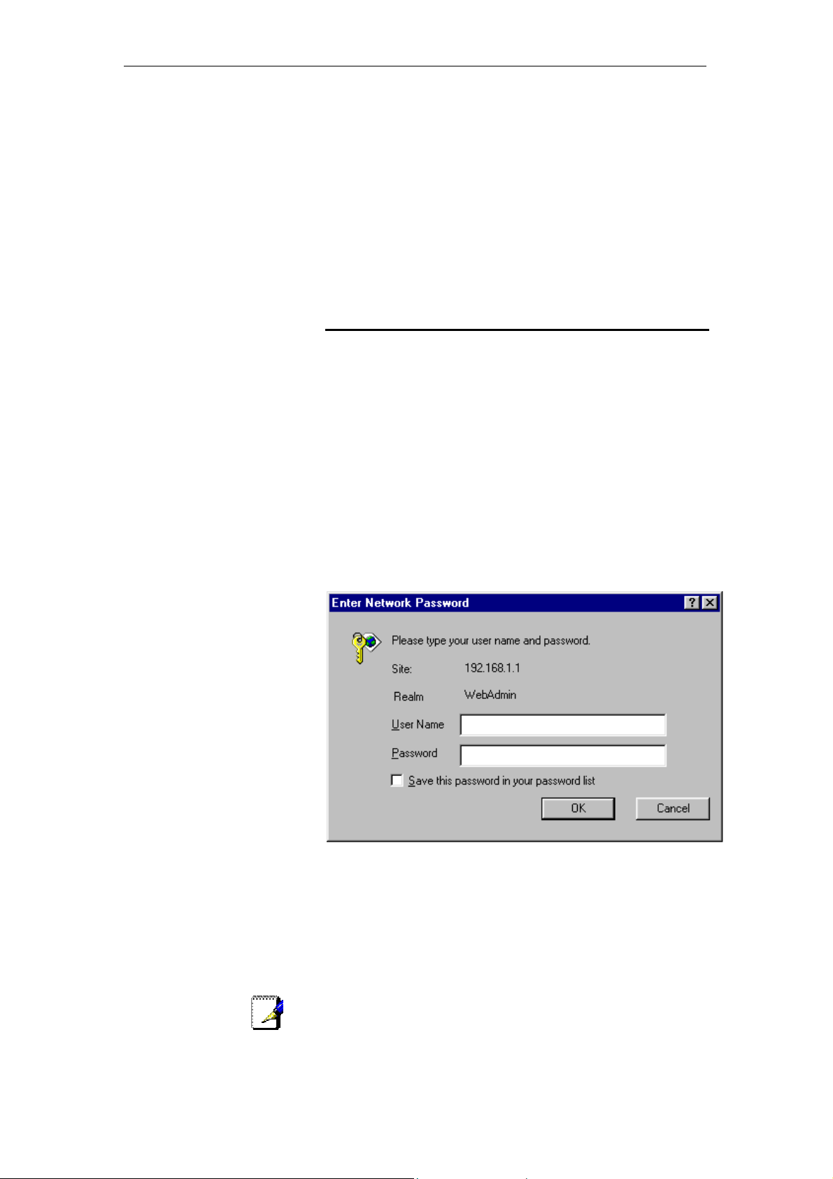
1. From any of the LAN c omputers, open yo ur w eb browse r,
type the following URL in the w eb address (or locati on) box,
and press [Enter] on your keyboard:
http://MyDslModem
the LAN, WLAN or USB ports.
錯誤! 尚未定義樣式。
A login screen is displayed:
Figure 5: Login screen
2. Enter your use r name an d passw ord. The first ti me you l og
into the program, use these def aults:
User Name:
Password:
admin
admin
You can change the password at any time or y ou can c onfigur e
your device so that you do not need to enter a password. See
Note
19
Password on page 77.
Page 20
錯誤! 尚未定義樣式。
User’s Guide
錯誤! 尚未定義樣式。
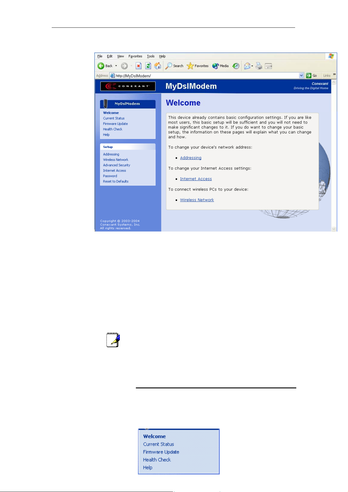
3. Click OK. The Welcome page is displayed:
Figure 6: The Welcome page
This is the first page displayed e ach time you log in t o the We b
pages (see Accessing the Web pages on page 19). This page
contains links to the following pa ges:
•
Addressing; links to the Addressing page that controls your
device’s network address. See Addressing on page 42.
•
Internet Access; links to the Internet Access page that
controls how your device connects to the Internet. See
Internet Access on page 66.
•
Wireless Network; links to the Wireless Network page that
controls how your wireless PCs connect to your device. See
Wireless Network on page 44.
Note
If you receive an error messag e or the W elcome p age is not
displayed, see Troubleshooti ng Suggest ions on page 10 2.
Web page menu overview
The web pages provide informat ion that allow s you to confi gure
your device. These pages are liste d in the me nu on the lefthand side of the screen. Click on an ind ividual m enu entry t o
display a page.
20
Notice that the menu is split
into two separate lists. The
Page 21
錯誤! 尚未定義樣式。
User’s Guide
錯誤! 尚未定義樣式。
first list contains entries that displ ay gener al inform ation ab out
the device including links to the pages t hat you are m ost likely to
want to use:
•
Welcome; see Accessing the Web pages on page 19
•
Current Status; see Current Status on page 25
•
Firmware Update; see Check for Updates on page 27
•
Health Check; see Health Check on page 32
•
Help; see Help on page 40
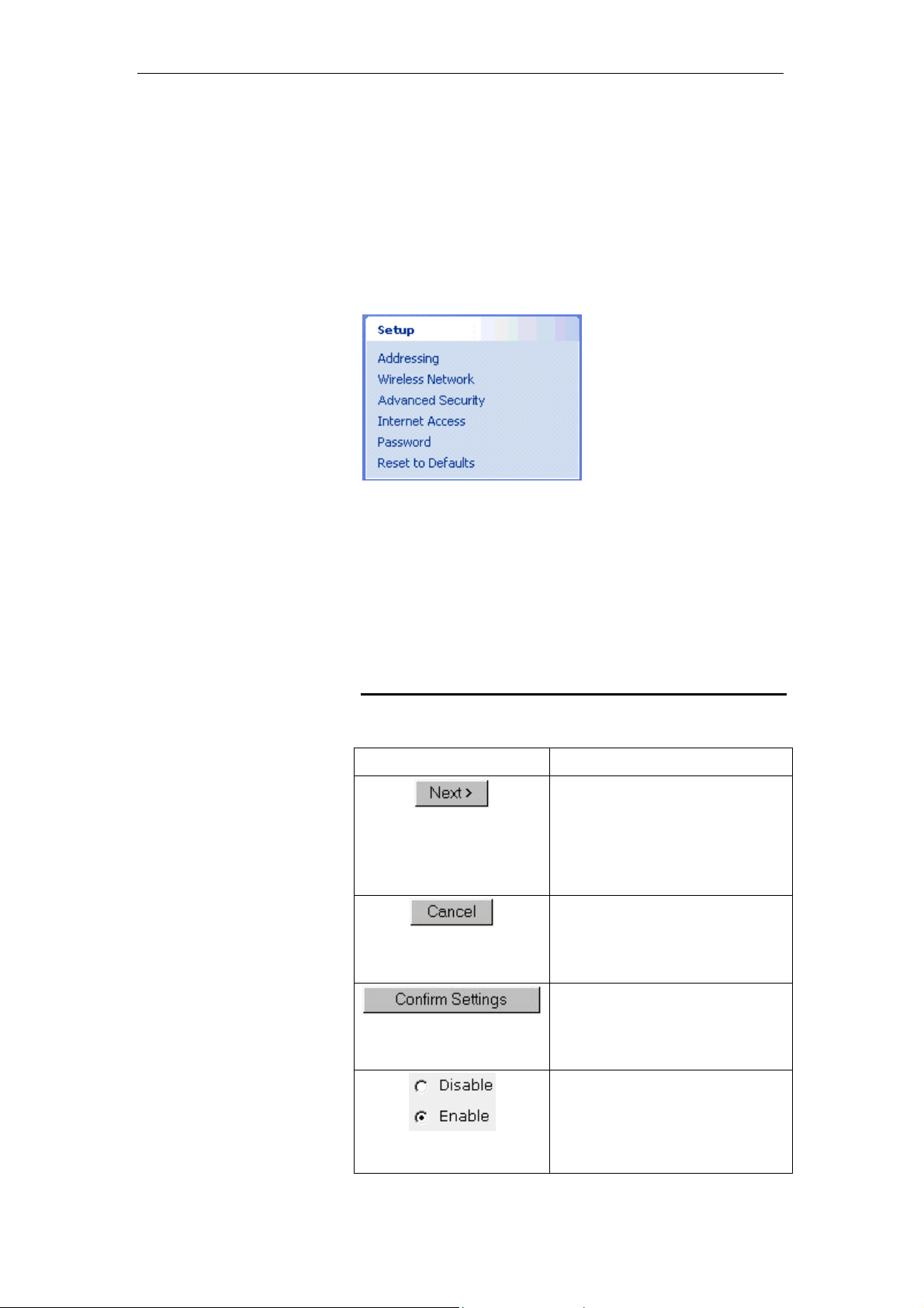
The Setup list contains
entries that allow you to
change the default settings
on your device. If you are
like most users, you may not
need to change these
settings, but if you do, the
Web pages will guide you
through each stage of this
process.
•
Addressing; see Addressing on page 42
•
Wireless Network; see Wireless Network on page 44
•
Security; see Security on page 58
•
Internet Access; see Internet Access on page 66
•
Password; see Password on page 80
•
Reset to Defaults; see Reset to Defaults on page 80
Commonly used buttons
The following buttons are used th roughout the w eb pages:
Button Function
You may need to configure the
settings on more than one page in
order to change some of the device’s
default settings. Click on this button
once you have changed the
configuration on your current page
and are ready to move on to the next.
This button appears on every
configuration page. Click on this
button if at any time you decide that
you do not want to change the existing
settings.
This button appears on the final page
of a series of configuration pages.
Click on this button to confirm that you
are happy with the changes that you
have made and want to save them.
Radio buttons – these appear on
many configuration pages. You will be
asked to select one radio button from
the selection of two or more available.
You cannot select more than one
radio button at a time.
21
Page 22
錯誤! 尚未定義樣式。
User’s Guide
錯誤! 尚未定義樣式。
The following terms are used throughout this guid e in
association with these buttons:
•
Click – point the mouse arrow over the button, menu entry
or link on the screen and click the left mouse button. This
performs an action, such as displaying a new page.
•
Select – usually used when descr ibing w hich radi o butt on to
select from a list, or which entry to select from a drop-down
list. Point the mouse arrow over the entry and left-cl ick to
select it. This does not perform an action – you will also be
required to click on a button, menu entry or link in order to
proceed.
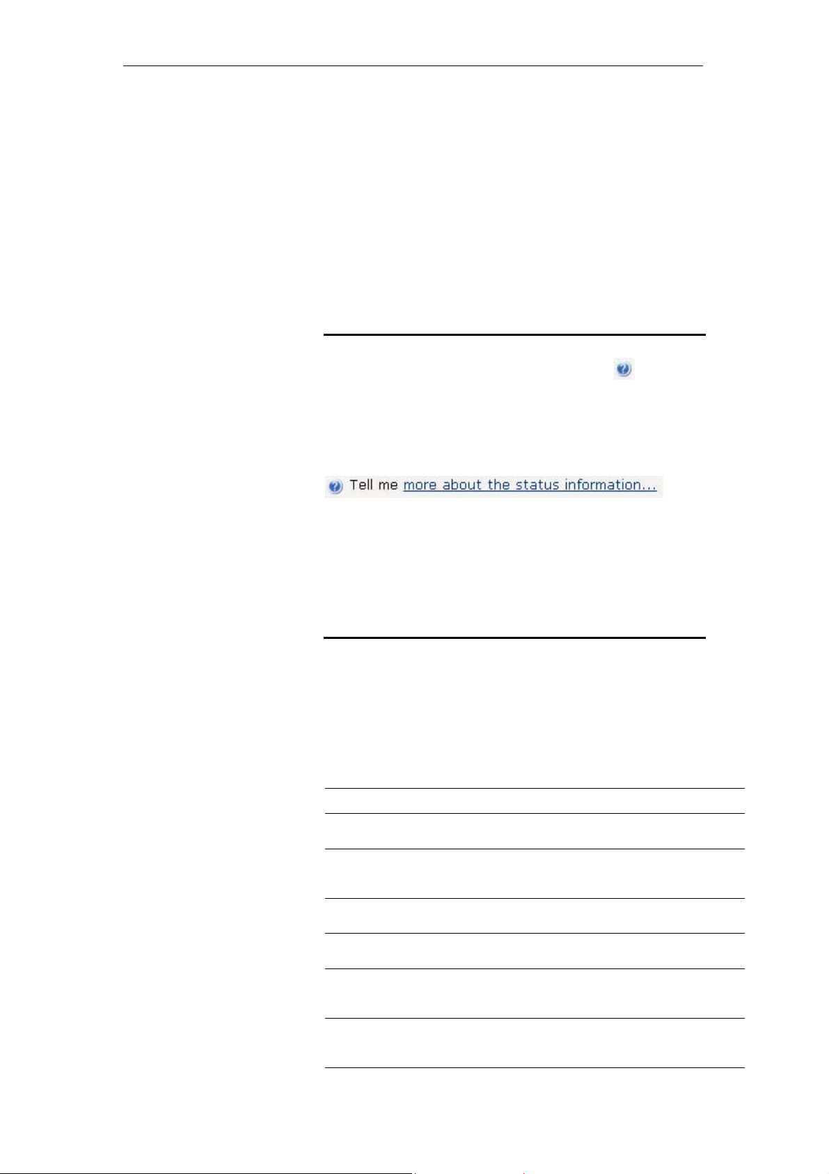
Help information
In addition to these buttons, you w ill also see t he information
icon throughout the Web pages. The information icon is
followed by a link (called a hyperlink) to another w eb page. Click
on the hyperlink to display furth er informa tion about a specific
configuration setting. For example, at the Current Status page,
clicking on the following hyperli nk:
displays further information about the details disp layed on the
Current Status page.
If you want to display an index of the He lp info rmation a vailabl e
for all web pages, see Help on page 40.
Testing your Setup
Once you have connected your hardware and configured your
PCs, any computer on your LAN should be a ble to use t he
device’s DSL connection to access the Inte rnet.
To test the connection, turn on the devic e, wait for 3 0 seconds
and then verify that the LED s are ill uminat ed as foll ows:
Table 1. LED Indicators
LED Behavior
Power
Internet
USB
W-LAN
LINK/Act
LINK/Act LAN
LINK/Act DSL
Solid green to indicate that the device is turned on. If thi s
light is not on, check the power cable attachment.
Flashing on/off while data is being transferred. Solid
orange when a valid IP address has been assigned to the
device by the ISP.
Solid green to indicate that the USB connection is
operational.
Solid green to indicate that the Wireless LAN connection is
operational.
Flashing on/off while the device is booting. After about 1015 seconds, solid green to indicate that the device can
communicate with your LAN.
Flashing on/off while data is being transmitted. Solid green
to indicate that the device has successfully established a
connection with your ISP.
22
Page 23

錯誤! 尚未定義樣式。
User’s Guide
錯誤! 尚未定義樣式。
LINK/Act DSL
Flashing when the device is sending or receiving data from
the Internet. It may be unlit, flashing, or appear solid
depending on the current activity.
The initial Argon 4x1 Customer Evaluation Board only supports
the green Power LED (D1705 – TOP). This table is provid ed as
an example of the LEDs that your product may support. You
must edit this table to reflect your own LED configuration.
[CT25]
If the LEDs illuminate as expected, test your Int ernet co nnection
from a LAN computer (and from the USB com puter, if
applicable). To do this, open you r web br owser, and ty pe th e
URL of any external website (such as http://www.yahoo.com
).
The LED labeled LINK/Act DSL should be blinking rapidly and
may appear solid as the device connects to the site.
If the LEDs do not illuminate as expected, you may need to
configure your Internet access settings usi ng the informa tion
provided by your ISP. For details, see Internet Access on page
66. If the LEDs still do not illuminate as ex pected, or t he w eb
page is not displayed, see Troubleshooting Suggesti ons on
page 102, or contact your ISP for assistance.
Default device settings
Option Default Setting Explanation/Instructions
DSL Port IP
Address
LAN Port
IP Address
DHCP (Dynamic
Host Configuration
Protocol)
In addition to handling the DSL connection t o your ISP , the DSL
Modem can provide a variety of services t o your netw ork. The
device is preconfigured w ith default s ettings for use w ith a
typical home or small office network.
The table below lists some of the most imp ortant default settings;
these and other features are desc ribed f ully in the s ubseq uent
chapters. If you are familiar with netw ork conf iguration, review
these settings to verify that t hey m eet the ne eds of y our network.
Follow the instructions to change the m if necessa ry. If you are
unfamiliar with these settings, try using th e device w ithout
modification, or contact your ISP for assistance.
Before you modify any settings, we strongly recommend that
you contact your ISP prior to changing the default configuration.
Unnumbered interface:
192.168.1.1
Subnet mask:
255.255.255.255
Assigned static IP address:
192.168.1.1
Subnet mask:
255.255.255.0
DHCP server enabled with the
following pool of addresses:
192.168.1.2
through
192.168.1.20
This is the temporary public IP address of the WAN
port on the device. It is an unnumbered interface that
is replaced as soon as your ISP assigns a ‘real’ IP
address. See Internet Access on page 66.
This is the IP address of the LAN port on the device.
The LAN port connects the device to your Ethernet
network. Typically, you will not need to change this
address. See Addressing on page 42.
The 錯誤! 尚未定義樣式。 maintains a pool of private
IP addresses for dynamic assignment to y our LAN
computers. To use this service, you must have set up
your computers to accept IP information dynamically,
as described in Configuring Ethernet PCs on page 82.
23
Page 24

錯誤! 尚未定義樣式。
Option Default Setting Explanation/Instructions
NAT (Network
Address Translation)
User’s Guide
NAT enabled
錯誤! 尚未定義樣式。
Your computers’ private IP addresses (see DHCP
above) will be translated to your public IP address
whenever they access the Internet. See Security on
page 58.
24
Page 25
錯誤! 尚未定義樣式。
User’s Guide
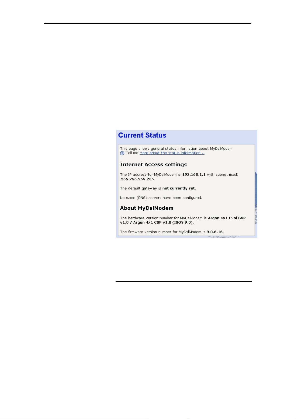
5 Current S tatus
The Current Status page displays useful inform ation about the
setup of your device, including:
•
•
To display this page:
From the left-hand menu, click on Current Status. The following
page is displayed:
錯誤! 尚未定義樣式。
details of the device’s Internet acc ess settings
version information about your device
Figure 7: Current Status page
The information displayed on this page is explained in detail in
the following sections.
Internet access settings
This section displays details of the settings that allow your
device to access the Internet. Thes e detail s include:
IP address and
subnet mask:
Default gateway: The address of the ISP server through
DNS servers: The Domain Name System (DNS)
The IP address and subnet mask
assigned to your WAN interface. This
address is used temporarily unt il your
ISP assigns a real IP address (via DHCP
or PPP – see Internet Access on page
66).
which your Internet connection will be
routed.
servers used by your ISP to map domain
25
Page 26

錯誤! 尚未定義樣式。
User’s Guide
names to IP addresses.
錯誤! 尚未定義樣式。
Note
Your ISP assigns all of these settin gs. In most cas es, you
not
need to make changes to these settings in order for your
Internet connection to work. If your ISP does ask you to change
any of these settings, follow the inst ruction s for manu ally
configuring your device in Internet Access on page 66.
The address 192.168.1.1 subnet mask 255.255.255.255 means
that your WAN interface is an unn umbered interf ace. Fo r more
information on unnumbered interfaces, see Glossary on page
106.
About Productname
This section displays details of your device ’s hardw are and
firmware versions. If you need to contact your IS P’s support
team, they may need to know which hardware/firmware
versions you are using in order to answer your query.
Your hardware version deta ils contai n informati on about the
make and model of your device and its ex act hardw are
components.
Your firmware version detail s contain i nformat ion abo ut the
software program running on your device. From time to time,
Zoom Telephonics may update or add new features to this
firmware. They then make the latest updated version available
to you via the Internet. For details of how to up date you r
firmware, see Check for Updates on page 27.
will
26
Page 27

錯誤! 尚未定義樣式。
User’s Guide
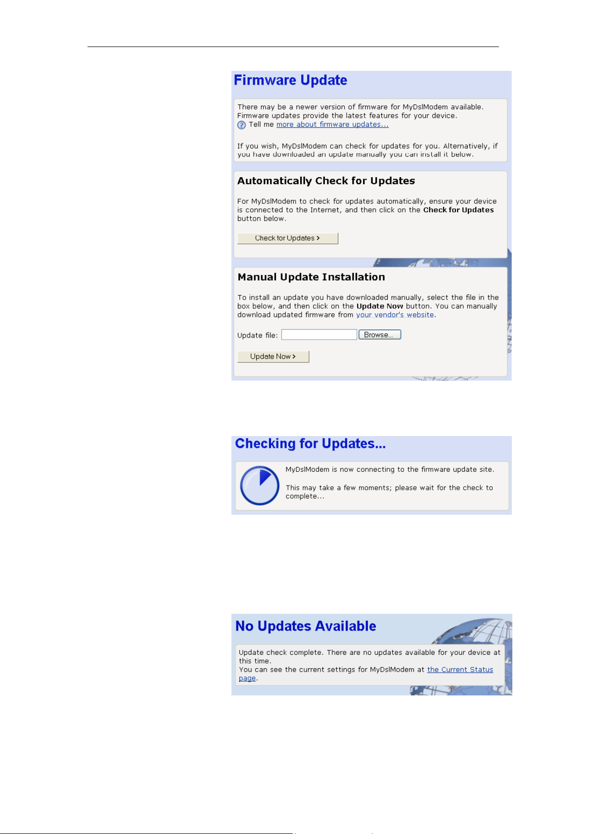
6 Firmware Update
The Firmware Updat e page allow s you to:
•
check if an updated firmware versio n is avail able f rom
Zoom Telephonics. See Checking for firmware updates on
page 27.
•
download an updated firmwa re versi on and i nstall it on y our
device. See Updating your firmware on page 29.
•
manually download the late st firmware v ersion fro m Zoom
Telephonics’s website and manually update your firmware.
See Manually updating firmware on page 30.
About firmware versions
Firmware is a software program. It is stored as read-only
memory on your device. Zoom Telephonics is continually
improving this firmware by adding new features t o it, and thes e
features are saved in later v ersions of t he firmw are.
錯誤! 尚未定義樣式。
Note
Your device can check whether t here a re later f irmware
versions available. If there is a l ater ve rsion, you ca n dow nload
it via the Internet and install it o n your dev ice.
If there is a firmware update available yo u are strongly advised to
install it on your device to ensure that you take full advantage of
any new feature developments.
In order to check and download firmware, your device must be
attached to the Internet. To check this, se e Testing your Setup
on page 22.
Checking for firmware updates
1. From the left-hand menu, c lick on Firmwa re Update. The
following page is displayed:
27
Page 28
錯誤! 尚未定義樣式。
User’s Guide
錯誤! 尚未定義樣式。
Figure 8: Firmware Update page
2. Click Check for Updates>. The Checking for Updates…
page is displayed:
Figure 9: Checking for Updates… page
3. This page tells you that a c heck for up dates is in p rogress.
Once the check is complete, the page dis played de pends
on whether updates are available or not.
If there are no firmware upda tes av ailable
•
the
following page is displayed:
Figure 10: No updates available page
This confirms that you are already using the latest
firmware version and there are no updat es available.
28
Page 29
錯誤! 尚未定義樣式。
User’s Guide
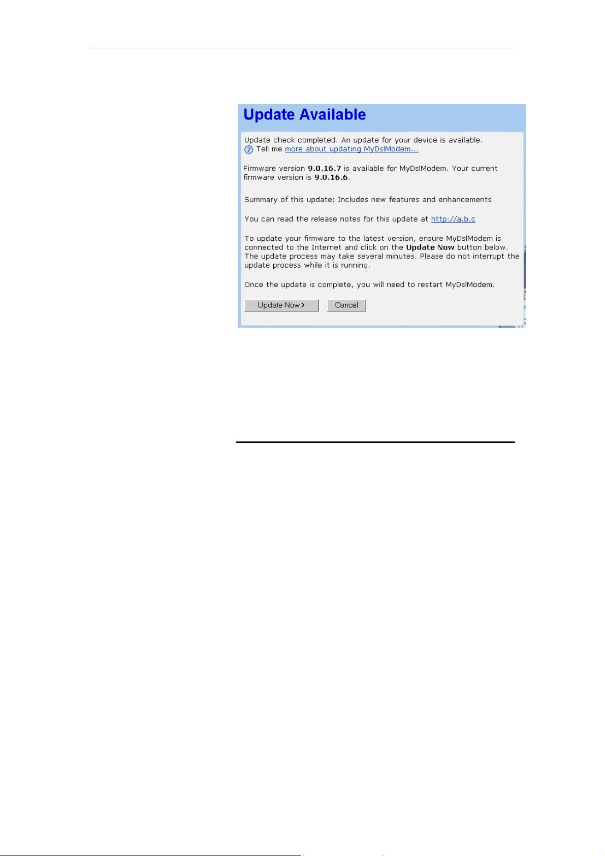
If there are firmware updates available
•
page is displayed:
錯誤! 尚未定義樣式。
, the following
Figure 11: Update Available page
The page includes a summary of th e firmw are updat e,
and a link to the release not es.
For instructions on updating your firmware, see Updating
your firmware on page 29.
Updating your firmware
This section assumes that you have alre ady carried o ut one of
the following:
•
followed the instructions in Checking for firmware updates
on page 27.
•
followed the instructions on man ually upd ating fi rmware in
Manually updating firmware on page 30.
If the Updates Available page h as confi rmed t hat a fi rmw are
update is available, follow the instruct ions below .
1. From the Update Available page, click Update Now>. The
Checking for Updates… page is displayed. Once the device
has connected to the firmware updat e site, the foll owing
page is displayed:
29
Page 30
錯誤! 尚未定義樣式。
User’s Guide
錯誤! 尚未定義樣式。
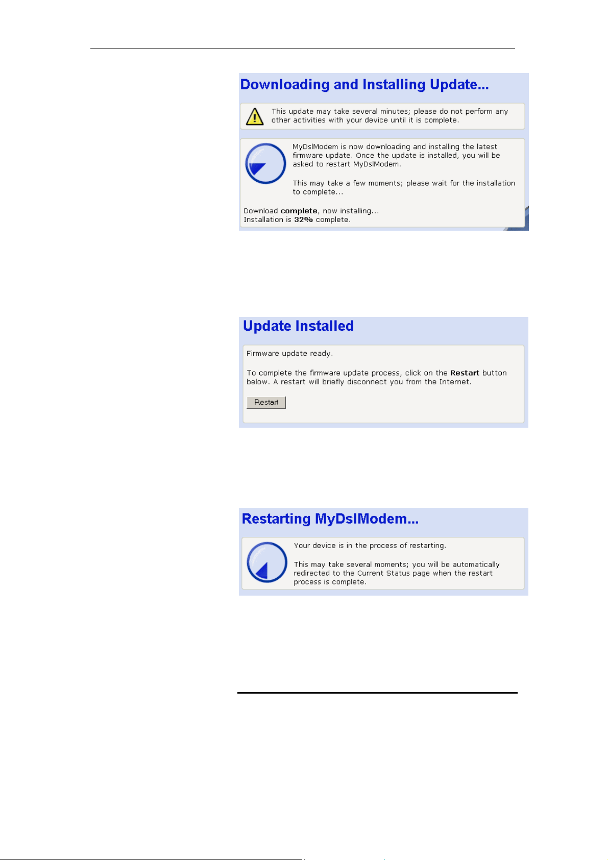
Figure 12: Downloading and installing update… page
2. The page tells you t hat the firmw are updat e is curre ntly
being downloaded and install ed on y our device.
Once installation is complete, the foll owing p age is
displayed:
Figure 13: Update Installed page
3. You must restart your device in order to make the device
aware that a new firmware version h as been installed. T o
do this, click Restart Productname . The f ollow ing page is
displayed:
Figure 14: Restarting page
The page tells you that your device is cu rrently bein g
restarted. Once complete, the Current Status page is
displayed. See the Current Status on page 25.
Manually updating firmware
You can manually download the lat est firmware ve rsion f rom
Zoom Telephonics’s website to your PC’s file directory. Click on
the Zoom Telephonics link.
Once you have downloaded the latest firmware version to your
PC, you can manually select and install it as fo llow s:
30
Page 31

錯誤! 尚未定義樣式。
User’s Guide
錯誤! 尚未定義樣式。
1. Click on the Browse… button.
Figure 15: Manual Update Installation section
(Note that if you are using c ertain browsers (s uch as Opera
7) the Browse button is labeled Choos e.)
Use the Choose file box to navigate to the relevant directory
where the firmware version is saved.
2. Once you have selected the file t o be inst alled, click Open.
The file’s directory path is displayed in the Update file: text
box.
3. Click Update Now>. The device checks that the selected
file contains an updated version of firmw are. Now follow the
instructions from Checking for firmwa re updat es, step 3 on
page 28.
31
Page 32

錯誤! 尚未定義樣式。
User’s Guide
7 Health Check
錯誤! 尚未定義樣式。
This page allows you to run a healt h chec k to test whet her th e
Internet connection on your device is working properly. The
health check runs a number of tests in order to diagnose any
‘health’ problems with your device’s Internet access.
If you need to contact your ISP’s support team, they may ask
you to run the Health Check and describe t he results t o them.
This page also provides you with a link to the DSL Stat us page,
which displays detailed info rmation a bout your DS L connect ion.
See the DSL Status page on page 34.
Running the Health Check
1. From the left-hand menu, c lick on Healt h Check. The
following page is displayed:
Figure 16: Health Check page
This page asks you to ensure th at your d evice is co nnected
to your phone line. See Step 1. Connect the DSL cable a nd
optional telephone on page 17.
2. Click on Perform Health Check>. The following page
confirms that the health check is currently runni ng:
Figure 17: Health Check: Running page
The Health Check may take up to three mi nutes to
complete.
32
Page 33

錯誤! 尚未定義樣式。
User’s Guide
錯誤! 尚未定義樣式。
3. Once the health ch eck has fi nished runni ng, the Health
Check: Complete page is displayed. The most important
details displayed on this page are the Result, Test and
Diagnostic information:
•
Result; tells you the overall result of the hea lth check
•
Test; if the Health Check fails, this tells you which test
caused the failure. The first failed test st ops the H ealth
Check completely – no other tests are ru n after t he
failed test. If the Health Check is successfully
completed, ‘User Diagnostics complete’ is displayed.
•
Diagnostic; if the Health Check fails, this provides
technical information about the likely caus e of a Health
Check failure. If a failure occurs, you will need to give
this information to your ISP’s support team. If the Health
Check is successfully completed, no diagnostic
information is displayed.
For example, if you run the Health Check on your device
when the DSL port is not connect ed, the f ollow ing
information may be displayed:
Figure 18: Health Check: Complete with failures page
This page tells you that the result failed. The test t hat
caused the health check to fail was the ph ysical connect ion
test. The diagnostic information displays details about the
failure that you can pass on to your ISP support team.
This page also contains links to the Cu rrent Status and
Internet Access pages. It may be worth checking th e
settings on these pages if the health check failed.
If you want to run the health check again, c lick on the
Health Check page link at the bottom of this page, or from
the left-hand Setup menu, click on Health Check. The
Health Check page is displayed (see Health Check page on
page 32).
If your device successfully passes the health check, the
following page is displayed:
33
Page 34

錯誤! 尚未定義樣式。
User’s Guide
錯誤! 尚未定義樣式。
Figure 19: Health Check: Complete with no failures page
DSL Status page
1. From the left-hand menu, c lick on Healt h Check. The
following page is displayed:
Figure 20: Health Check page
2. Click on DSL Status. The following page is dis played:
34
Page 35

錯誤! 尚未定義樣式。
User’s Guide
錯誤! 尚未定義樣式。
Figure 21: Health Check: DSL Status page
This page displays useful inform ation a bout the status of your
DSL connection, including:
•
Operational mode; the current connected mode. Possible
values displayed are:
•
Inactive (not connected)
•
Unknown (unrecognized mode)
•
Name of the standard compliance used by the
connection (for example, G.Span+ ).
•
State; the current state of the device. Possibl e values
displayed are:
•
Idle (not connected or attempting to connect)
•
Handshake (hunting for a re mote mode m)
•
Training (remote modem has been found)
•
Showtime (connected to the remote modem)
•
Trained transmit/receive bit rate; the transmit an d receive
rates of the device (in bits per second).
3. Click on the DSL port conf igurat ion… link at the t op of t he
Health Check: DSL Status page. The following page is
displayed:
35
Page 36

錯誤! 尚未定義樣式。
User’s Guide
錯誤! 尚未定義樣式。
Note
Note
Figure 22: DSL Port Basic Configuration page
In addition to information about the stat us of your DS L
connection (also displayed on the Health C heck: DSL
Status page), this page displays the current att ribute
settings for your DSL port and allow s you to configu re these
settings. The DSL port is called port A1.
You should
told you to do so and/or you a re experi enced in DSL attribut e
configuration. For details of the attributes and o ptions displayed,
see Advanced DSL port attributes on page 106.
4. Once you have configured DSL port attri butes, click on
Apply. The page is refreshed and th e devi ce is upd ated with
your DSL configuration changes. C licking on Reset
you have clicked on Apply will reset attribute values to their
previous settings.
5. You can also dis play an d configure advan ced DSL port
attributes. At the top of the Port A 1 Configurati on page, click
on the View advanced configuratio n… The page displ ayed
contains the advanced attrib utes show n on the f ollow ing
two pages.
You should
your ISP has told you to do so and/or y ou are experi enced in D SL
attribute configuratio n. For details of the att ributes and opt ions
displayed, see Advanced DSL port attri butes on pa ge 106.
only
edit your DSL port configuration if your ISP has
only
edit your advanced DSL port c onfigu ration if
before
36
Page 37

錯誤! 尚未定義樣式。
User’s Guide
錯誤! 尚未定義樣式。
Figure 23: Port A1 Advanced Configuration page (part 1)
37
Page 38

錯誤! 尚未定義樣式。
User’s Guide
錯誤! 尚未定義樣式。
38
Page 39

錯誤! 尚未定義樣式。
User’s Guide
錯誤! 尚未定義樣式。
Figure 24: Port A1 Advanced Configuration page (part 2)
6. Once you have configu red advanced DSL po rt attributes,
click on Apply. The page is refreshed and the device is
updated with your DSL configurat ion cha nges. Clickin g on
before
Reset
you have clicked on Apply will reset attribute
values to their previous settings.
For details of the advanced DSL port attributes displ ayed, see
Advanced DSL port attributes on page 106.
39
Page 40

錯誤! 尚未定義樣式。
8 Help
User’s Guide
錯誤! 尚未定義樣式。
The Help page displays an index of the help information that
corresponds with each web pag e.
You can click on the
order to display further information abo ut a specific to pic on a
specific page. However, you may prefer to display the Help text
index in order to navigate through Help topics more easily.
information icon on any web page in
Using the Help page
1. From the left-hand menu, c lick on Help. The Help page is
displayed:
Figure 25: Help page
Notice that the Help headings match the menu headings
listed in the left-hand menu.
2. Each heading is a link to another help page. Click on a
heading to display information about a specific page in a
new window. For example, clicking on Current Status
displays the Help: Current Status page. The same page is
displayed by clicking on the information ic on from th e
Current Status page itself.
3. The new w indow that dis plays the help pa ges conta ins the
following left-hand menu:
40
Page 41

錯誤! 尚未定義樣式。
User’s Guide
錯誤! 尚未定義樣式。
Figure 26: Help – Close link
To close the new window , click on close.
About the Online User Guide
Although this guide can be pri nted for e asy referenc e, it has
also been prepared for view ing onl ine thro ugh a w eb brow ser.
To view the online version of this g uide, f rom the Help index
page, click on the Online User Guide link. The online version of
this guide is displayed.
41
Page 42

錯誤! 尚未定義樣式。
User’s Guide
9 Addressing
Note
錯誤! 尚未定義樣式。
The Addressing page displays information about your LAN IP
address and allows you to change the address and subnet
mask assigned to your device.
You should only change the addressing details if your ISP asks
you to, or if you are familiar with netw ork conf igurati on. In most
cases, you will not need to make any changes to this
configuration.
Changing the LAN IP address and subnet mask
1. From the left-hand Setup menu, click on Addressing. The
following page is displayed:
Note
Figure 27: Addressing page
This page displays the current IP address and subnet mask
assigned to your device. The default LAN IP configuration is
IP address 192.168.1.1, subnet mask 255.255.255.0.
2. Click on Change Productname Address settings here…
The following page is displ ayed:
Figure 28: Addressing: Setup page
3. Click in the IP Address and Subnet Mask boxes and type
the new address details.
Your LAN PCs must remain on the same sub net as your device
(that is, the subnet masks must be the same). If necessa ry,
reconfigure the LAN PCs so that their IP address es place them in
the same subnet as the new dev ice IP a ddress. See C onfigu ring
Ethernet PCs on page 82.
42
Page 43

錯誤! 尚未定義樣式。
User’s Guide
錯誤! 尚未定義樣式。
4. Click Next>. The following page is displayed:
Figure 29: Addressing: Confirm page
5. This page displays th e new IP address and subnet mask
and asks you to confirm whether these are correct. Click
Confirm Changes. The Addressing page is displayed,
confirming your new LAN address settings.
Note
If you change the LAN IP address of the device while connected
through your Web browser, you will be disconnected. You must
open a new connection by entering your new LAN IP address as
the URL. See Accessing the Web pages on page 19.
43
Page 44

錯誤! 尚未定義樣式。
User’s Guide
10 Wireless Network
This chapter assumes that you have already set up your
Wireless PCs and installed a compatible Wireless card on y our
device. See Configuring Wireless PCs on page 96.
The Wireless Network page allows you to configu re the
Wireless features of your device. To acc ess the Wireless
Network page:
From the left-hand Setup menu, click on Wireless Network. The
following page is displayed:
錯誤! 尚未定義樣式。
Figure 30: Wireless Network page
The settings on this page are split into tw o sections:
•
First Time Settings
takes you through a sequence of pag es, with eac h pag e
corresponding to a specific wireless netw ork settin g. You
should only need to change all of these settings once; i.e.,
when you initially setup your w ireless n etw ork. See the
Wireless Network First Time Settings Wizard on page 45.
This section also displays the country that the wireless
network is set to operate in and the type of wireless network
used.
•
General Settings; contains details of the current wireless
configuration and hyperlinks relating to indivi dual wirel ess
network settings previously configured by completin g the
First Time Settings wizard. This allows you to make
44
[CT33]
; contains a hyperlink wizard th at
Page 45

錯誤! 尚未定義樣式。
User’s Guide
錯誤! 尚未定義樣式。
changes to specific wireless settings w ithout going th rough
the entire wizard. See Wireless Network General Settings
on page 55.
Wireless Network First Time Settings Wiz ard
This section describes how to foll ow the w ireless netw ork
wizard in order to configure your wirel ess netw ork settings fo r
the first time. The wizard seque nce allow s you to c onfigure each
of the following Wireless settings in ord er:
•
The country that your network is operating in
•
The specification standard u sed by the w ireless n etwork
•
The wireless network name
•
The wireless network channel
•
Wireless network security
•
Wireless network address authentication
Note
Each page of the wizard contains a Cancel button. Clic k on this if
you want to exit the wizard at any time.
[CT34]
Setting the Country
1. From the First Time Settings section of the Wireless
Network page, click Change your wireless first time settings
here… The first page of the wizard is dis played:
Figure 31: Wireless Network: Set Country page
The number of valid wireles s netw ork frequenci es vari es
from country to country and you need to identify which
country you are operating the device in to ensure that your
network will transmit on the correct frequency.
2. From the Country drop-down list, select the appropriate
country. Click on the Confirm Changes> button to apply
configuration changes and move on to the next page in the
wizard sequence, which allows you to Select y our Wireless
Network Type.
[CT35]
Select your Wireless Network Type
The following page allows you to select the IEEE specification
supported by your network:
45
Page 46

錯誤! 尚未定義樣式。
User’s Guide
錯誤! 尚未定義樣式。
Figure 32: Wireless Network: Wireless Network Type Selection
page
Each specification transmits at a c ertai n speed (measu red in
Mbits per second) over a specific frequency. The frequency
indicates the range at which wireless t raffic can b e transmitt ed
or received between the dev ice and t he wirel ess PC(s).
Supported specifications are:
•
802.11B only – provides slow er rates at a longe r range t han
802.11G (11 Mbps in the 2.4 GHz band)
•
802.11G only – provides faste r rates at a s horter range tha n
802.11B (20+ Mbps in the 2.4 GHz band)
•
802.11B/G – supports both of the above specifications, but
802.11G rates will be slower than they are in a G-only
network
Note
Some Argon platforms also support 802.11A only, which provides
54Mbps in the 5 GHz band. The A rgon 4x 1 does not s upport
802.11A.
To select a network type, click on a single radio button. Click on
the Confirm Changes> button to apply configuration changes
and move on to the next page in the w izard sequenc e, which
allows you to Set the Wireless Network Name.
Set the Wireless Network Name
The following page allow s you to s et the nam e of your w ireless
network:
Figure 33: Wireless Network: Basic page
Your device and all of the wireless PCs in you r wireless LAN
share the same wireless netw ork name. This nam e (comm only
known as the Service Set Identifier (SSID) distinguishes your
46
Page 47

錯誤! 尚未定義樣式。
User’s Guide
錯誤! 尚未定義樣式。
Wireless network from any other(s) that may be i n use nearby. It
also ensures that only those PCs configur ed with th e same
name as the one set on your dev ice can o btain access t o it.
By default, the network name starts with GSV_ and ends with
the last six digits of your device’s MAC address. For security
reasons, we recommend that you replac e the defa ult netw ork
name with a unique value of you r ow n.
To do this:
1. Click in the Network Name (SSID) box and type a new
name. The name can be any combi nation of n umbers
and/or letters with a maximum length of 3 2 charact ers.
2. Click Next>.
If you are following the First Time Settin gs wizard, the next page
in the wizard sequence is displ ayed, which allow s you to Select
a Channel.
If you have accessed this page fr om the General Settings
section of the Wireless Network page, click on the Confirm
Changes button to apply chan ges and return t o the Wireless
Network page.
Select a Channel
The following page allow s you to s elect a netw ork cha nnel:
Figure 34: Wireless Network: Channel Selection page
Your device and all of the wireless PCs in you r wireless LAN
must share the same channel number. Each channel
represents a regulatory channel frequency (MHz). Some
countries may regulate the use of certain channel frequencies.
Your ISP determines which channels are availab le and whethe r
you should allow automatic o r manual c hannel sel ection.
To configure channel selecti on, choos e one of t he follow ing
options:
•
If you want the device to automatically sel ect the best
channel for your network, click on the Allow MyDslModem
to select channel option and then click Next>.
•
If you want to manually select a channel, click on the Select
a channel manually option and then click Next>. The
following page is displayed:
47
Page 48

錯誤! 尚未定義樣式。
User’s Guide
錯誤! 尚未定義樣式。
Figure 35: Wireless Network: Channel Selection (manual) page
Select a suitable channel (as advised by your ISP) f rom the
Channel drop-down list and then click Next>.
If you are following the First Time Settin gs wizard, the next page
in the wizard sequence is displ ayed, which allow s you to
Configure Wireless Network Security.
If you have accessed this page from the General Settings
section of the Wireless Network page, click on the Confirm
Changes button to apply chan ges and return t o the Wireless
Network page.
Configure Wireless Network Security
The following pag e allow s you to c onfigu re w ireless security:
Figure 36: Wireless Network: Security page
You can protect your wireless dat a from potentia l
eavesdroppers by encrypting wireless data transmissions. An
eavesdropper might set up a com patibl e wireless ad apter w ithin
range of your device and attempt to acc ess your network. Data
encryption is the translation of data i nto a form t hat cann ot be
easily understood by unauthorized users.
There are two methods of wireless securit y to choose fr om:
•
Wired Equivalent Privacy (WEP); data is encrypted into
blocks of either 64 bits length or 128 bits length. The
encrypted data can only be sent and received by users w ith
access to a private network key. Each PC on your wireless
network must be manually configu red w ith the same k ey as
your device in order to allow wireless encrypted data
transmissions. Eavesdroppers cannot access your network
if they do not know your private key. WEP is considere d to
be a low security option.
48
Page 49

錯誤! 尚未定義樣式。
User’s Guide
錯誤! 尚未定義樣式。
•
Wi-Fi Protected Access (WPA); provides a stronger data
encryption method (calle d Temporal Key Integ rity Proto col
(TKIP)). It runs in a special, easy-to-set -up hom e mode
called Pre-Shared Key (PSK) that allows you to manually
enter a pass phrase on all the d evices in y our wirel ess
network. WPA data encryption is b ased o n a WPA mas ter
key. The master key is derived from the pass phrase and
the network name (SSID) of the device.
To configure security, choose one of the follow ing options:
•
If you do not want to use Wireless Network security, click
the Off radio button and then click Next>. Off is the default
setting, but you are
strongly recommended
to use
wireless network security on your device.
If you are following the First Time Settings wizard, the next
page in the wizard sequence is displayed, which all ows you
to Configure Wireless Address Authentication.
If you have accessed this page fr om the General Settings
section of the Wireless Network page, click on the Confirm
Changes button to apply changes and return to t he
Wireless Network page.
•
If you want to use WEP 64bit data enc ryption, c lick on th e
64bit encryption on the wireless network radio button and
then click Next>. Now follow the instructions in Configuring
64bit or 128bit encryption on page 49.
•
If you want to use WEP 128bit data encryption, click on the
128bit encryption on the w ireless netw ork radio button a nd
then click Next>. Now follow the instructions in Configuring
64bit or 128bit encryption on page 49.
•
If you want to use WPA, click on the Wi-Fi Protected
Access (WPA) on the wireless network radio button and
then click Next>. Now follow the instructions in Configuring
WPA security on page 50.
Configuring 64bit or 128bit encryption
The example set in this section is for 128bit encryption, however
the outline also applies to 64bit encryption.
1. Once you have selected your WEP encryption method and
then clicked Next>, the following page is displayed:
Figure 37: Wireless Network: 128bit Network Key page
2. Click in the Key box and type a unique 26-character hex
network key, such as A6F34B2CE5D68BE90A6F34B2CE.
Note
49
Hexadecimal or ‘hex’ numbers eac h have a valu e of 0 to 9 o r A to
F. Each number represents four bits of binary data.
Page 50

錯誤! 尚未定義樣式。
User’s Guide
錯誤! 尚未定義樣式。
Note that if you selected 64bit, you will need to type a
unique 10-character hex network key.
3. Click Next>.
If you are following the First Time Settin gs wizard, the next page
in the wizard sequence is displ ayed, which allow s you to
Configure Wireless Address Authentication.
If you have accessed this page from the General Settings
section of the Wireless Network page, click on the Confirm
Changes button to apply chan ges and return t o the Wireless
Network page.
Configuring WPA security
1. Once you have selected WPA and then clicked Next>, the
following page is displayed:
Figure 38: Wireless Network: Wi-Fi Protected Access page
2. Type a unique pass phrase in the Pass phrase text box.
Your pass phrase should be at least 2 0 characters l ong in
order to deter potential intruders.
3. Once you have typed a pass phrase, click Next>.
If you are following the First Time Settin gs wizard, the next page
in the wizard sequence is displ ayed, which allow s you to
Configure Wireless Address Authentication.
If you have accessed this page from the General Settings
section of the Wireless Network page, click on the Confirm
Changes button to apply chan ges and return t o the Wireless
Network page.
Configure Wireless Address Authentication
The following page allow s you to c onfigu re w hich wireless PCs
can access the device:
50
Page 51

錯誤! 尚未定義樣式。
User’s Guide
錯誤! 尚未定義樣式。
Figure 39: Wireless Network: Address Authentication page
By default, any wireless PC that is configured with your
network’s SSID and channel number can connect to your
device. You may want to increase t he security of your w ireless
network by creating one of the fol lowing l ists of w ireless PCs:
•
a wireless PC blacklist; PCs on this list
device, but all other wireless PCs
•
a wireless PC whitelist; PCs on this list
device, but all other wireless PCs
cannot
can
.
can
cannot
access the
access the
.
The Wireless PCs added to either list are identified by their
unique MAC address. This is made up of six pairs of characters,
with each character either a number betw een 0 and 9, or a letter
between A and F. For example, 00:20:2 b:80: 2f:30.
To configure which wireless PCs ca n access your dev ice,
choose one of the following opt ions:
•
If you want any wireless PCs to have access to your device,
click on the Allow any wireless PCs to connect radio button.
Click Next>.
If you are following the First Time Settings wizard, the final
page in the wizard sequence is displayed, which all ows you
to Confirm Wireless network changes.
If you have accessed this page from th e General Settings
section of the Wireless Network page, click on the Confirm
changes button to apply changes and return to the Wireless
Network page.
•
If you want to create a blacklist of PCs that cann ot access
your device, click on the Allow all wireless PCs to connect
except those I specify radio butt on and th en click Next>.
Now follow the instructions in Configuring the wire less PC
blacklist on page 51.
•
If you want to create a whitelist of PCs that can access your
device, click on the Only allow the wireless PCs I specify to
connect radio button and then click Next>. Now follow the
instructions in Configuring the wireless PC whitelist on page
53.
Configuring the wireless PC blacklist
1. Once you have selected Allow all wireless PCs to connect
except those I specify radio butt on and th en clicke d Next>>,
the following page is displayed:
51
Page 52

錯誤! 尚未定義樣式。
User’s Guide
錯誤! 尚未定義樣式。
Figure 40: Wireless Network: Address Authentication (blacklist)
page
2. To add a network PC to the blacklist, click Add an address
here… The following page is dis played:
Figure 41: Wireless Network: Address Authentication (blacklist)
page
3. Click in each box and type each character pair of the MAC
address for the PC you want to blacklist. Click Next>. The
following page is displayed, cont aining d etails of t he MAC
address that you have just added:
Figure 42: Wireless Network: Address Authentication (blacklist)
page
4. This page allows you to configure the addresses on the
blacklist:
•
If you want to add another MAC address to the blacklist,
click Add an address here… and repeat the instructions
described in step 3.
•
If you want to remove a MAC address from the blacklist,
click Remove an address here… At the displayed page,
select the MAC address that you want to remove from
the drop-down list.
52
Page 53

錯誤! 尚未定義樣式。
User’s Guide
錯誤! 尚未定義樣式。
5. Click Next>.
If you are following the First Time Settin gs wizard, the final page
in the wizard sequence is displ ayed, which allow s you to
Confirm Wireless network changes.
If you have accessed this page from the General Settings
section of the Wireless Network page, click on the Confirm
Changes button to apply chan ges and return t o the Wireless
Network page.
Configuring the wireless PC whitelist
1. Once you have selected Only allow the wireless PCs I
specify to connect radio button and t hen cl icked Next>, the
following page is displayed:
Figure 43: Wireless Network: Address Authentication (whitelist)
page
2. To add a network PC to the whitelist, click Add an address
here… The following page is dis played:
Figure 44: Wireless Network: Address Authentication (whitelist)
page
3. Click in each box and type each character pair of the MAC
address for the PC you want to whitelist. Click Next>. The
following page is displayed, cont aining d etails of t he MAC
address that you have just added:
53
Page 54

錯誤! 尚未定義樣式。
User’s Guide
錯誤! 尚未定義樣式。
Figure 45: Wireless Network: Address Authentication (whitelist
configuration) page
4. This page allows you to configure the addresses on the
whitelist:
•
If you want to add another MAC address to the whitelist,
click Add an address here… and repeat the instructions
described in step 3.
•
If you want to remove a MAC address from the whitelist,
click Remove an address here… At the displayed page,
select the MAC address that you want to remove from
the drop-down list.
5. Click Next>.
If you are following the First Time Settin gs wizard, the final page
in the wizard sequence is displ ayed, which allow s you to
Confirm Wireless network changes.
If you have accessed this page from the General Settings
section of the Wireless Network page, click on the Confirm
Changes button to apply chan ges and return t o the Wireless
Network page.
Confirm Wireless network changes
Once you have configured Wireless Address Authentication and
clicked on Next>, the following page is displayed:
Figure 46: Wireless Network: Confirm page
This page confirms the configurati on changes made to each
page in the wizard. If you are happy w ith these setti ngs, click on
54
Page 55

錯誤! 尚未定義樣式。
User’s Guide
錯誤! 尚未定義樣式。
the Confirm Changes button. Configuration changes are applied
to the device and the Wireless Network page is displayed.
Once you have completed the First Time Settings w izard, you
can edit specific wireless settin gs using t he hyp erlinks di splayed
in the General Settings section of the Wireless Network page.
See Wireless Network General Settings on page 55.
Wireless Network General Settings
The General Settings section of the Wireless Network page
displays details of the device’s current w ireless confi gurati on.
For example:
Figure 47: Wireless Network: General Settings section
The hyperlinks in this section all ow you to:
•
Enable/disable wireless netw orking; s ee Enabling/ disa bling
wireless networking on page 56.
•
Change the channel currently in use; click Change your
wireless channel here… and follow the instructions in
Select a Channel on page 47.
•
Change the network name (SSID); click Change your
wireless network name here… and follow the instructions in
Set the Wireless Network Name on page 46.
•
Configure wireless security; click Change Wireless Security
settings here… and follow the instruction in Configure
Wireless Network Security on page 48.
•
Configure address authentication; click Change which
wireless PCs are allowed to connect here… and follow the
instructions in Configure Wireless Address Authentication
on page 50.
•
Display information about the wireless PCs connected to
the device; see Displaying details of Wireless PCs on page
56.
55
Page 56

錯誤! 尚未定義樣式。
User’s Guide
Enabling/disabling wireless networking
錯誤! 尚未定義樣式。
Note
Once you have completed the First Time Settings wizard,
wireless networking is enabled on the device by default.
At the Wireless Network page, click on Enable or disable the
wireless network here… The following page is displayed:
Figure 48: Wireless Network: Enable/Disable page
Choose whether to enable o r disable w ireless netw orking:
•
To enable the network, click on the Enable radio button and
then click Next>. This takes you through a subset of the
First Time Setting wizard, starting with the page that allows
you to configure the current Wireless Network Name.
Follow the instructions starting from Set t he Wireless
Network Name on page 46.
•
To disable the network, click on t he Disable radio butt on
and then click Next>. The next page confirms the disabl ed
state of the wireless network. If you are happy w ith this
configuration, click on Confirm Changes. The Wireless
Network page is displayed.
Displaying details of Wireless PCs
At the Wireless Network page, click on View details of
connected wireless PCs… The following page is displayed:
Figure 49: Wireless Network: Connected Wireless PCs page
< bad grammar on this page: “The following 1 w ireless PCs
are..@>
This page displays the MAC address of the PC currently
connected to your device, together with the signal strength. The
signal strength is the measure of radio frequency (R F) energy
56
Page 57

錯誤! 尚未定義樣式。
User’s Guide
錯誤! 尚未定義樣式。
detected by the device on a specific channel. Signal strength
may vary depending on the position of the PC(s) in relation to
the device.
To return to Wireless Network page, click on Return to the
wireless status page.
57
Page 58

錯誤! 尚未定義樣式。
User’s Guide
11 Advanced Security
Your device has built in advanced Securit y features th at protect
your network by blocking unwanted t raffic from t he Internet.
If you simply want to connect from your local network to the
Internet, you do not need to make any changes to the default
Security configuration. You only need to e dit the confi guration if
you wish to do one or both of the fol lowing:
•
allow Internet users to browse the user pages on your local
network (for example, by providing an FTP or HTTP server)
•
play certain games which require access ibility f rom the
Internet
This chapter describes how to configure Security to suit the
needs of your network.
錯誤! 尚未定義樣式。
By default, the IP addresses of your LAN PCs are hidden from
the Internet. All data sent from your LAN PCs to a PC on the
Internet appears to come from the IP address of your device.
(To display your device’s IP address, see Current Status on
page 25.) In this way, details about your LAN PCs remain
private. This security feature is called Network Address
Translation (NAT).
Configuring NAT Security
Certain network games, chat or file sharing software do not
work with your default NAT setting. Your device knows the port,
protocol and trigger inf ormation needed t o allow access to the
common applications listed below, but by default, acces s to
them is disabled.
Application TCP
port
number
E-mail 110, 25 N/A false
News 119 N/A false
MSN Messenger 1863 N/A false
5050
Yahoo! Instant Messenger
AOL Instant Messenger 5190 N/A false
Internet Relay Chat (IRC) 194 194 false
Netmeeting (h323)
5055
5100
1720 N/A true
N/A 1719 true
1731
522
UDP
port
number
N/A false
N/A false
Trigger
required?
58
Page 59

錯誤! 尚未定義樣式。
User’s Guide
錯誤! 尚未定義樣式。
Application TCP
port
number
Real Audio
Ping
Web connections (HTTP,
HTTPS)
DialPad
FTP 21 N/A false
Telnet 23 N/A false
Secure shell (SSH) 22 N/A false
Windows Media Services 1755 1755 false
Gnutella 6346 N/A false
Kazaa 1214 N/A false
Windows Terminal Server 3389 N/A false
DNS N/A 53 false
PPTP 1723 1723 false
Internet Key Exchange N/A 500 false
LDAP 389 N/A false
GRE
Databeam (T.120) 1503 N/A false
544
7070
N/A
(ICMP)
80, 443 N/A false
51210 N/A true
N/A
N/A
(GRE)
UDP
port
number
544
6770
N/A
(ICMP)
51200
51201
N/A
(GRE)
Trigger
required?
false
false
true
false
You can enable access to a common ap plicati on from a specific
PC on your network. For more information, see Configuring
Internet applications on page 61.
If you want to allow access to an applicati on that is
not
included
on the above list of common appl ications, you can c reate and
enable a custom application. For more information, see
Configuring custom applicatio ns on page 63.
Before you can configure your default NA T settings, y ou must
assign a unique name to each of t he PCs on y our netw ork. See
Assigning PC Names on page 59.
Assigning PC Names
You must assign a name to each of th e PCs on y our netw ork
before you can enable acce ss to common applicatio ns or c reate
custom ones. This allows you to refer to PC s by name instea d
of IP address.
1. From the left-hand Setup menu, click on Security. The
following page is displayed:
59
Page 60

錯誤! 尚未定義樣式。
User’s Guide
錯誤! 尚未定義樣式。
Figure 50: Advanced Security page
2. Click on Configure named PCs here… The fo llow ing page
is displayed:
Figure 51: Advanced Security: PC Names page
3. This page displays the names previously assigned to PCs
on your network. To assign a na me to an unnamed PC,
click Add a new PC name here… The follow ing page is
displayed:
Figure 52: Advanced Security: Add PC Name page
4. Type a unique, meaningful name in the PC name text box,
then type the IP address of the PC that yo u want to ass ign
this name to. Click Next>. The following page is displayed:
60
Page 61

錯誤! 尚未定義樣式。
User’s Guide
錯誤! 尚未定義樣式。
Figure 53: Advanced Security: Add PC Name page
5. If you are happy with the name that you have assigned to
the IP address, click Confirm Changes. The Advanced
Security: PC Names page is displayed.
Once you have assigned PC names, you can enable I ntern et
access to applications (see Configuring Internet applicat ions on
page 61) and create custom appl ications (see Confi guri ng
custom applications on page 63).
Deleting PC Names
To delete an assigned PC name:
1. From the Advanced Security: PC Names page, click on
Remove a PC name here…
2. Select the PC name that you wish to remove, and then click
Next>.
3. At the Advanced Security: Confirm PC Name page, click
Confirm Changes. The Advanced Security: PC Names
page is displayed. Details of the del eted PC nam e have
been removed.
Configuring Internet applications
This section assumes that you have already assigned names to
the PCs on your network as described in Assigning PC Names
on page 59.
You can enable/disable a specific Int ernet ap plicatio n in ord er to
allow/block access to it via an individual P C.
Enabling Internet applications
1. From the left-hand Setup menu, click on Advanced Security.
At the displayed page, click on Configure Inte rnet
applications here… The follow ing page is displayed:
Figure 54: Advanced Security: Enabled Applications page
61
Page 62

錯誤! 尚未定義樣式。
User’s Guide
錯誤! 尚未定義樣式。
This page displays details about ap plicati ons that ar e
currently enabled. By default, all Internet applications are
disabled.
2. Click on Enable an application here… Th e follow ing page is
displayed:
Figure 55: Advanced Security: Enable Application page
3. This page allows you to select which application you w ish to
enable for a specific PC. The Application nam e drop-down
list contains the following:
•
the common applications that your device know s about
(see Configuring Inte rnet ap plicatio ns on page 61).
•
any custom applications that you have ma nually
configured (see Configuring custom ap plications on
page 63).
Select the application and the PC t hat you want to en able
access to and then click Next>. The following page is
displayed:
Figure 56: Advanced Security: Confirm Application page
4. If you are happy with your application configuration, click
Confirm Changes. The Advanc ed Securit y: Enable d
Applications page is displayed, containing a list of currently
enabled applications.
Disabling Internet applications
1. From the Advanced Security: Enable d Applic ations page,
click on Disable an application here. Th e follow ing page is
displayed:
62
Page 63

錯誤! 尚未定義樣式。
User’s Guide
錯誤! 尚未定義樣式。
Figure 57: Advanced Security: Disable Application page
2. Select the application that you want to disable from the
Application name drop down list, and then click Next>. At
the Advanced Security: Confirm Application page, click on
Confirm Changes. The Advanced Secu rity: Enab led
Applications page is displayed. D etails ab out the d isabled
application have been removed.
Configuring custom applications
If you want to enable access to an applicat ion th at does not
appear on your device’s default list of common applications (see
Configuring Internet applicatio ns on pag e 61) you can creat e a
custom application.
In order to create a custom appl ication, y ou must k now:
1. the protocol used by the application (e.g., TCP, UDP and
so on)
2. the primary port or range of ports used by the application
3. whether the application requires a trigger, and if so, t he
secondary port or range of ports used by the application
4. the address translation type used by the trigger
Your application provider or games manufacturer should
provide you with these detail s.
Creating custom applications
In this example configuration, a c ustom app lication c alled
network game using TCP port 5555 is created.
1. From the left-hand Setup menu, click on Security. At the
Advanced Security page, click on Create and config ure
custom applications here… The following page is displayed:
Figure 58: Advanced Security: Custom Applications page
63
Page 64

錯誤! 尚未定義樣式。
User’s Guide
錯誤! 尚未定義樣式。
This page displays details of previously c reated custo m
applications. . By default, no custom applications exist.
Click Add a custom application h ere… The fo llow ing page
is displayed:
Figure 59: Advanced Security: Create Application page
2. Type a unique name for your custom application, and select
the transport protocol from the Transport drop-down list.
Click Next>. The following page is displayed:
Note
Figure 60: Advanced Security: Add Port page
3. Type a port range by entering the start and end of the range
in the two boxes provided. If you w ant to us e a single port,
enter the port number in the first box and l eave the s eco nd
box blank.
You must ensure that the single p ort or rang e specifi ed does not
overlap with a port or range for an existing common or custom
application. Check the common port rang es listed i n Configurin g
NAT Security on page 58.
Select the address translation type from the drop down list.
This controls the translation of bina ry IP address es in the
payload of a packet (the part containing data). Click Next>.
The following page is displ ayed:
64
Page 65

錯誤! 尚未定義樣式。
User’s Guide
錯誤! 尚未定義樣式。
Figure 61: Advanced Security: Confirm Custom Application page
4. This page confirms your custom application configuration. If
you are happy with the details displ ayed, click Confirm
Changes. The Advanced Security: Custom Applications
page is displayed, containing details of the custom
application that you have ju st created.
In order to access your custom application, you must first
enable it. See Configuring Internet ap plicatio ns on page 61.
Deleting custom applications
1. From the Advanced Security: Custom Ap plicatio ns page,
click on Delete a custom applicatio n here. .. The foll owing
page is displayed:
Figure 62: Advanced Security: Disable Application
2. Select the application that you want to delete from the
Application name drop down list and then click Next>. At
the Advanced Security: Confirm Application page, click on
Confirm Changes. The Advanced Security: Custom
Applications page is displayed. D etails ab out the d eleted
application have been removed.
65
Page 66

錯誤! 尚未定義樣式。
User’s Guide
12 Internet Access
This chapter describes how to configure the way that your
device connects to the Internet. Your ISP determines what type
of Internet access you should use and p rovides you w ith any
information that you need in order to c onfigure t he Int ernet
access to your device.
Your device needs the following address information in order to
access the Internet:
錯誤! 尚未定義樣式。
IP address and
subnet mask:
Default gateway: The gatew ay address that identifies the
DNS servers: The Dynamic Name System (DNS)
In most cases, you
these addresses because your IS P is likel y to use an I ntern et
access type which automatically assigns addresses to your
device. For more information, see Types of Internet Access on
page 66.
The IP address and subnet mask
assigned to your WAN interface.
ISP server through which your Internet
connection will be routed.
servers used by your ISP to dynamically
assign addresses to each of the
computers attached to your LAN.
will not
need to configure your device with
Types of Internet Access
The types of Internet access available a re as follow s:
•
Automatic Internet access – your device scans the Int ernet
via the DSL connection in order to find a link to th e ISP’s
Internet service. The IP addresses required to access your
ISP’s Internet service are automatically configured.
•
PPP Internet access – your device uses a Point to Point
Protocol (PPP) to carry data between your ISP and your
computer. To use PPP Internet access, you must enter a
PPP login username and password the first time to log
on. The IP addresses required to access your ISP’s
Internet service are automatically confi gured.
Your device supports two types of PPP – PPPoE (over
Ethernet) and PPPoA (over ATM).
•
DHCP – your ISP uses a protocol called Dynamic Host
Configuration Protocol (DHCP) to assign addr esses and
manage your device. The device is automatically assi gned
the IP addresses that it needs to access the Int ernet.
•
Manual – you manually assign the addresses that your
device needs in order to access the Internet. Your ISP
should provide you with the necessary addresses.
66
Page 67

錯誤! 尚未定義樣式。
User’s Guide
錯誤! 尚未定義樣式。
Configuring Automatic Internet Access
Your device can automatically search for a link to your ISP’s
Internet service. If your ISP tells you to use this connection
method, follow the instructions below .
1. From the left-hand Setup menu, click on Internet Access.
The following page is displ ayed:
Figure 63: Internet Access page
This page displays information about you r current Inte rnet
access configuration.
2. Click on Change the Internet Access setting here… The
following page is displayed:
Figure 64: Internet Access: Types of Access page
3. Select Auto and click Next>. The following page is
displayed:
Figure 65: Internet Access: Auto page
67
Page 68

錯誤! 尚未定義樣式。
User’s Guide
錯誤! 尚未定義樣式。
4. This page displays a warning that once a new connecti on is
automatically detected, it w ill replace y our existin g Internet
Access configuration. If you are happy w ith this, click Next>.
The following message conf irms that y our device is
automatically searching for a li nk to the I nternet:
Figure 66: Internet Access: Searching page
5. Once the search is complete, a page is displayed
confirming which type of Internet connecti on has bee n
detected. For example, the following page is dis played if the
device has detected a PPP connection:
Figure 67: Internet Access: PPP Setup page
6. Enter the PPP username and password provided by your
ISP. Type them in the relevant boxes, and then click Next>.
The following page is displ ayed:
Figure 68: Internet Access: Search Complete page
7. This page confirms the Internet Access settings that have
been detected. Click on the hyperlink to the Internet Access
page to display details of your automatic ally configure d
Internet connection.
Configuring your PPP DSL connection
If your ISP’s Internet service uses PPPoA or PPPoE you need
to set up a PPP login account. The first time that you lo gin to th e
Internet, your ISP will ask you to enter a username and
68
Page 69

錯誤! 尚未定義樣式。
User’s Guide
錯誤! 尚未定義樣式。
password so they can check that you are a legitim ate,
registered Internet service user. Yo ur devi ce stores t hese
authentication details, so you will not have to enter this
username and password every time you login.
Your ISP may also tell you to set unique path and circuit
numbers (called VPI and VCI) in order to connect your device to
the ISP’s Internet service. In most cases, your device w ill use
default settings, so you may not need to enter t hese val ues.
Note
Your ISP will provide you with the login details and VPI/VCI
values necessary to set up a PPP login account.
If your ISP wants you to connect to the Internet using PPP,
follow the instructions below.
1. From the left-hand Setup menu, click on Internet Access.
The following page is displ ayed:
Figure 69: Internet Access page
This page displays information about you r current Inte rnet
access configuration.
2. Click on Change the Internet Access setting here… The
following page is displayed:
Figure 70: Internet Access: Types of Access page
3. Select either PPPoA or PPPoE, depending on which PPP
type your ISP wants you to use. In this example, PPPoA is
selected, but the instructions for PPPoE are identical. Click
Next>. The following page is displ ayed:
69
Page 70

錯誤! 尚未定義樣式。
User’s Guide
錯誤! 尚未定義樣式。
Figure 71: Internet Access: PPPoA page
4. Enter the PPP username and password provided by your
ISP. Type them in the relevant boxes, and then click Next>.
The following page is displ ayed:
Figure 72: Internet Access: VPI and VCI Setup page
5. Click on the VCI and VPI setting determined by your ISP:
•
Fixed (default) - click on this if your ISP tells you to use
default VPI and VCI setting. This is the most common
setup.
•
Manual – click on this if your ISP has provided you with
specific VPI and VCI settings. Click Next>. At the next
page, type the provided VPI and VCI settings in the
relevant boxes.
6. Click Next>. The following page is displayed:
Figure 73: Internet Access: Confirm page
This page confirms your PPP settings. If you selected the
Manual option at step 5, the VPI and VCI values that you
entered are also displayed on th is page.
7. If you are happy with your settings, click Confirm Changes.
The Internet Access page is displayed.
70
Page 71

錯誤! 尚未定義樣式。
User’s Guide
錯誤! 尚未定義樣式。
If you have configured PPPoE Internet access, notice that an
extra configuration option call ed MAC Spoofing appears on this
page:
Figure 74: Internet Access: PPPoE page
MAC spoofing allows you to set the Media Access Control
(MAC) address of your device. S ee Enabl ing MAC spoofin g on
page 10 for more details.
Note
Note
Enabling MAC spoofing
You should only enable MAC spoofing if your ISP has requested
that you do so. In most cases, you will
Your ISP identifies your modem by its un ique hardw are nu mber
or Media Access Control (MAC) address. If you are usin g
PPPoE Internet access, your ISP may want you to spoof the
identity of a different device. You can spoof the MAC address of
another device by replacing your device’s existing MAC address
with another device’s addres s. Your ISP w ill provid e you w ith
the replacement MAC address.
You can only configure MAC spoofing if you are using PPPoE
Internet access. This option is not available for PPPoA.
If your ISP instructs you to change your device’s default MAC
address, follow the instructions below :
1. From the Internet Access page, click Enable or disable
MAC Spoofing here… The following page is displayed:
not
need to do this.
71
Page 72

錯誤! 尚未定義樣式。
User’s Guide
錯誤! 尚未定義樣式。
Figure 75: Internet Access: MAC Spoofing page
2. Select Enabled then click Next>. The following page is
displayed:
Figure 76: Internet Access: MAC Spoofing Setup page
3. The MAC address is made up of six pairs of characters.
Each character can be either a n umber b etw een 0 and 9, o r
a letter between A and F. For example, 00:20:2b: 80:2f:30.
Click in each box and type each character pair of the MAC
address provided by your ISP.
4. Click Next>. The following page is displayed:
Figure 77: Internet Access: MAC Spoofing Confirm
This page confirms your MAC spoofing settings. If you are
happy with these settings, click Confirm Changes. The
Internet Access page is displayed, and your MAC spoofing
configuration is complete.
Editing your existing MAC spoofing settings
If you want to change the spoof MAC addr ess used by you r
device, follow the instructions in En abling MAC sp oofing on
page 71, but replace the existing address with a new one at
step 3.
72
Page 73

錯誤! 尚未定義樣式。
User’s Guide
錯誤! 尚未定義樣式。
If you do not want to use MAC spoofing, foll ow the inst ructions
in Enabling MAC spoofing on page 71, but select Disabled at
step 2.
Configuring your DHCP DSL connection
If your ISP uses a DHCP DSL connection, your ISP may tell you
to set unique path and circuit numbers (called VPI and VCI) in
order to connect your device to the ISP’s Internet service. In
most cases, your device will use default settings, so y ou may
not need to enter these values.
Note
Your ISP will provide you with the VPI/VCI values neces sary to
setup a DHCP DSL connection.
1. From the left-hand Setup menu, click on Internet Access.
The following page is displ ayed:
Figure 78: Internet Access page
This page displays information about you r current Inte rnet
access configuration.
2. Click on Change the Internet Access setting here… The
following page is displayed:
Figure 79: Internet Access: Types of Access page
3. Select DHCP then click Next>. The following page is
displayed:
73
Page 74

錯誤! 尚未定義樣式。
User’s Guide
錯誤! 尚未定義樣式。
Figure 80: Internet Access: VPI and VCI Setup page
4. At this page, click on the VCI and VPI setting determined by
your ISP:
•
Fixed (default) - click on this if your ISP tells you to use
default VPI and VCI setting. This is the most common
setup.
•
Manual – click on this if your ISP has provided you with
specific VPI and VCI settings. Click Next>. At the next
page, type the provided VPI and VCI settings in the
relevant boxes.
5. Click Next>. The following page is displayed:
Note
Figure 81: Internet Access: Confirm page
This page confirms your DHCP settings. If you sel ected the
Manual option at step 4, the VPI and VCI values that you
entered are also displayed on th is page.
6. If you are happy with your settings, click Confirm Changes.
The Internet Access page is displayed and your
configuration is complete.
Configuring your Internet Access manually
If your ISP tells you to configure your Internet access manually,
they must provide you with the follow ing in formati on:
•
The WAN IP address and subnet mask for your device
•
The Internet Gateway address
•
The primary and secondary DNS addresses
You should only change the Internet Access details if your ISP
asks you to, or if you are familiar with network configuration. In
most cases, you will not need to make any changes to this
configuration.
74
Page 75

錯誤! 尚未定義樣式。
User’s Guide
錯誤! 尚未定義樣式。
1. From the left-hand Setup menu, click on Internet Access.
The following page is displ ayed:
Figure 82: Internet Access page
This page displays information about you r current Inte rnet
access configuration.
2. Click on Change the Internet Access setting here… The
following page is displayed:
Figure 83: Internet Access: Types of Access page
3. Select Manual then click Next>. The following p age is
displayed:
Figure 84: Internet Access: Manual Setup page
4. Click in each box and type the relevant address information
provided by your ISP. Click Next>. The following page is
displayed:
75
Page 76

錯誤! 尚未定義樣式。
User’s Guide
錯誤! 尚未定義樣式。
Figure 85: Internet Access: VPI and VCI Setup page
5. At this page, click on the VCI and VPI setting determined by
your ISP:
•
Fixed (default) - click on this if your ISP tells you to use
default VPI and VCI settings. This is the most common
setup.
•
Manual – click on this if your ISP has provided you with
specific VPI and VCI settings. Click Next>. At the next
page, type the provided VPI and VCI settings in the
relevant boxes.
6. Click Next>. The following page is displayed:
Figure 86: Internet Access: Confirm page
This page confirms the address settings t hat you hav e
manually configured (the va lues dis played above a re for
example purposes only). If you sel ected th e Manual o ption
at step 5, the VPI and VCI values that you entered are also
displayed on this page.
7. If you are happy with your settings, click Confirm Changes.
The Internet Access page is displayed and your
configuration is complete.
76
Page 77

錯誤! 尚未定義樣式。
User’s Guide
13 Password
錯誤! 尚未定義樣式。
You can restrict access to your device’s web pages using
password protection. With passw ord protectio n enabled, use rs
must enter a username and password before gaini ng access to
the web pages.
By default, password protection is enabled on your device, and
the username and password set are as follows:
Note
Username:
Password:
For more information, see Accessing the Web pages on page
19.
admin
admin
Setting your username and password
Non-authorized users may try to guess your username and
password. They will find it easier to guess the default us ername
and password than to guess your own unique username and
password. We recommend that you change th e default username
and password to your own unique settings.
To set your own username and passw ord:
1. From the left-hand Setup menu, click on Password. The
following page is displayed:
Figure 87: Password page
This page displays the current status of p assword
protection.
2. Click on Change Password settings here… The following
page is displayed:
77
Page 78

錯誤! 尚未定義樣式。
User’s Guide
錯誤! 尚未定義樣式。
Figure 88: Password: Enable/Disable page
3. This page allows you to enable or disable password
protection. Protection is already enabled b y default. Clic k
Next>. The following page is displ ayed:
Figure 89: Password: Setup page
4. This page displays the current username and password
settings. Type your own unique use rname a nd passw ord in
the relevant boxes. They can be any combination of letters
or numbers with a maximum of 20 characters. The default
setting uses admin for both the username an d passw ord.
We recommend that you
do not
set the same character
combination for both use rname and pass word.
5. Click Next>. The following page is displayed:
Figure 90: Password: Confirm page
6. This page confirms that password protection is enab led and
displays the username that will be required in order to
access the web pages. If you are happy with t hese s ettings,
click Confirm Changes. The Enter Network Password login
box is displayed. You need to login to the web pages using
your new username and password. For details of how to do
this, see Accessing the Web pages on page 19.
78
Page 79

錯誤! 尚未定義樣式。
User’s Guide
錯誤! 尚未定義樣式。
Disabling password protection
If you do not want to use password prot ection, follow the
instructions in Setting your username and on page 77, and at
step 3, select Disable, then click Next>.
79
Page 80

錯誤! 尚未定義樣式。
User’s Guide
14 Reset to Defaults
This page allows you to reset your dev ice to its def ault factory
settings.
The configuration settings of you r device a re stored i n a
configuration file. When you set up your device an d access the
web pages for the very first time, th e confi guratio n file cont ains
a default factory configuration. T his config uration has been s et
by Zoom Telephonics for you, and contai ns the basic s ettings
that you can use without havin g to make e xtensive c hanges t o
the configuration.
If you do make changes to the default configuration but then
wish to revert back to the origi nal factory c onfigu ration, you c an
do so by resetting the devic e to facto ry defaults.
Resetting to Defaults
錯誤! 尚未定義樣式。
Note
If you reset your device to factory defaults, all previous
configuration changes that you have made are overw ritten by the
factory default configuration.
1. From the left-hand Setup menu, click on Reset to Defaults.
The following page is displ ayed:
Figure 91: Reset to Defaults page
2. This page reminds you that resetting to factory defaults
cannot be undone – any changes that you have made to
the basic settings will be replaced. If you are happy with this,
click in the Confirm box to tick it, then click Reset to
Defaults. The following page is displ ayed:
Figure 92: Resetting to Defaults…
80
Page 81

錯誤! 尚未定義樣式。
User’s Guide
Note
錯誤! 尚未定義樣式。
This page confirms that the device is current ly resetti ng to
factory defaults. Once the reset is complete, the Current
Status page is displayed. See Current Status on page 25.
Resetting to defaults also resets the username and password to
their default settings. If you previously changed the username and
password by following the instructions in P assword on page 77,
the Enter Current Password login box will be displayed.
Once you have entered the default s ettings (adm in, adm in) and
clicked OK, the Current Status page is displayed.
81
Page 82

錯誤! 尚未定義樣式。
A Configuring your Computers
User’s Guide Configuring your Computers
This appendix prov ides inst ructio ns f or co nfigu rin g the I nter net
settings on your computers to work with the 錯誤!
式。
.
尚未定義樣
Configuring Ethernet PCs
Before you begin
By default, the 錯誤! 尚未定義樣式。 automatically assigns the
required Internet settings to your PCs. You need only to
configure the PCs to ac cept the inf orm atio n w hen it is as signe d.
In some cases, you may want to assi gn Inte rnet inf ormation
錯
Note
manually to some or all of your computers rather than allow the
誤! 尚未定義樣式。
information to your PCs on page 88 for instructions.
• If you have connected your LAN PCs via Ethernet to the 錯
誤! 尚未定義樣式。, follow the inst ructions that corres pond
to the operating system installed on your PC:
• Windows® XP PCs on page 82
•
Windows 2000 PCs on page 84
•
Windows Me PCs on page 85
•
Windows 95, 98 PCs on page 86
•
Windows NT 4.0 workstations on page 86
•
If you have co nn ecte d a P C v ia th e U SB p ort, see
Configuring a USB PC on page 89.
•
If you want to allow Wireless PCs to access your device,
follow the instructions in Co nfiguring W ireless PC s on page
96.
to do so. See Assigning static Internet
Windows® XP PCs
1. In the Windows task bar, click the Start button, and then click
Control Panel.
2. Double-click the Network Connections icon.
3. In the LAN or High-Speed Internet window, right-click on the
icon corresponding to your network interface card (NIC) and
select Properties. (Often, this icon is labeled Local Area
Connection).
The Local Area Connection dialog box is displayed with a list
of currently ins talle d net wor k ite ms.
82
Page 83

錯誤! 尚未定義樣式。
User’s Guide Configuring your Computers
4. Ensure that the check box to the left of the item labeled
Internet Protocol TCP/IP is checked and click Properties.
5. In the Internet Protocol (TCP/IP) Pro pertie s dialog box, cli ck
the radio button labeled Obtain an IP address
automatically
. Also click the radio button labeled
Obtain
DNS server address automatically.
6. Click OK twice to confirm your changes, and then close the
Control Panel.
83
Page 84

錯誤! 尚未定義樣式。
User’s Guide Configuring your Computers
Windows 2000 PCs
First, check for the IP protocol and, if necessary, install it:
1. In the Windows task bar, click the Start button, point to
Settings
, and then click
Control Panel
.
2. Double-click the Network and Dial-up Connections icon.
3. In the Network and Dial-up Connecti ons win dow, right-c lick
the Local Area Connection icon, and then select Properties.
The Local Area Connection Properties dialog box is
displayed with a list of currently installed network
components. If the list includes Internet Protocol (TCP/IP),
then the protocol has already been enabled. Skip to step 10.
4. If Internet Protocol (TCP/IP) does not display as an installed
component, click Install….
5. In the Select Network Component Type dialog box, select
Protocol, and then click Add….
6. Select Internet Protocol (TCP/IP) in the Network Protocols
list, and then click OK.
You may be prompted to install files from your Windows
2000 installation CD or other media. Follow the instructions
to install the files.
7. If prompted, click OK to restart your computer with the new
settings.
Next, configure the PCs to accept IP information assigned by the
錯誤! 尚未定義樣式。:
8. In the Control Panel, double-click the Network and Dial-up
Connections icon.
9. In Network and Dial-up Connections window, right-click the
Local Area Connection icon, and then select Properties.
10. In the Local Area Connection Properties dialog box, select
Internet Protocol (TCP/IP), and then click Properties.
11. In the Internet Protocol (TCP/IP) Propertie s dialog box, cli ck
the radio button labeled Obtain an IP address
automatically. Also click the radio button labeled Obtain
DNS server address automatically.
12. Click OK twice to co nfirm and save your changes, and then
close the Control Panel.
84
Page 85

錯誤! 尚未定義樣式。
User’s Guide Configuring your Computers
Windows Me PCs
1. In the Windows task bar, click the Start button, point to
Settings, and then click Control Panel.
2. Double-click the Network and Dial-up Connections icon.
3. In the Network and Dial-up Connecti ons win dow, right-c lick
the Network icon, and then select Properties.
The Network Prope rties dialog box dis plays with a list of
currently installed network components. If the list includes
Internet Protocol (TCP/IP), then the protocol has already
been enabled. Skip to step 11.
4. If Internet Protocol (TCP/IP) does not display as an installed
component, click Add….
5. In the Select Network Component Type dialog box, select
Protocol, and then click Add….
6. Select
Microsoft
in the Manufacturers box.
7. Select Internet Protocol (TCP/IP) in the Network Protocols
list, and then click OK.
You may be prompted to install files from your Windows Me
installation CD or other media. Follow the instructions to
install the files.
8. If prompted, click OK to restart your computer with the new
settings.
Next, configure the PCs to accept IP information assigned by the
錯誤! 尚未定義樣式。:
9. In the Control Panel, double-click the Network and Dial-up
Connections icon.
10. In Network and Dial-up Connections window, right-click the
Network icon, and then select
Properties
.
11. In the Network Properties dialog box, select TCP/IP, and
then click
Properties
.
12. In the TCP/IP Settings dialog box, click the radio button
labeled Server assigned IP address. Also click the radio
button labeled Server assigned name server address.
13. Click OK twice to confirm and save your changes, and then
close the Control Panel.
85
Page 86

錯誤! 尚未定義樣式。
User’s Guide Configuring your Computers
Windows 95, 98 PCs
First, check for the IP protocol and, if necessary, install it:
1. In the Windows task bar, click the Start button, point to
Settings
, and then click
Control Panel
.
2. Double-click the Network icon.
The Network dialo g box dis plays w ith a list of cur rent ly
installed network components. If the list includes TCP/IP,
and then the protocol has already been enabled. Skip to step
9.
3. If TCP/IP does not display as an installed component, click
Add….
The Select Network Component Type dialog box displays.
4. Select
Protocol
, and then click
Add…
.
The Select Network Protocol dialog box displays.
5. Click on Microsoft in the Manufacturers list box, and then
click
TCP/IP
in the Network Protocols list box .
6. Click OK to return to the Network dia log box, and the n click
OK again.
You may be prompted to install files from your Windows
95/98 installation CD. Follow the instructio ns to install the
files.
7. Click OK to restart the PC and complete the TCP/IP
installation.
Next, configure the PCs to accept IP information assigned by the
錯誤! 尚未定義樣式。:
8. Open the Control Panel window, and then click the Network
icon.
9. Select the network component labeled TCP/IP, and then
click
Properties
.
If you have multiple TCP/IP listings, select the listing
associated with your network card or adapter.
10. In the TCP/IP Properties dialog box, click the IP Address tab.
11. Click the radio button labeled Obtain an IP address
automatically.
12. Click the DNS Configuration tab, and then click the radio
button labeled Obtain an IP address automatically.
13. Click OK twice to confirm and save your changes.
You will be prompted to restart Windows.
14. Click Yes.
Windows NT 4.0 workstations
First, check for the IP protocol and, if necessary, install it:
86
Page 87

錯誤! 尚未定義樣式。
User’s Guide Configuring your Computers
1. In the Windows NT task bar, click the Start button, point to
Settings, and then click Control Panel.
2. In the Control Panel window, double click the Network icon.
3. In the Network dialog box, c lick th e Pr otocols tab.
The Protocols tab displays a list of currently installed network
protocols. If the list includes TCP/IP, then the protocol has
already been enabled. Skip to step 9.
4. If TCP/IP does not display as an installed component, click
Add….
5. In the Select Network Protocol dialog b ox, selec t TCP/IP,
and then click OK.
You may be prompted to install files from your Windows NT
installation CD or other media. Follow the instructions to
install the files.
After all files are installed, a window displays to inform you
that a TCP/IP service called DHCP can be set up to
dynamically assign IP information.
6. Click Yes to continue, and then click OK if prompted to
restart your computer.
Next, configure the PCs to accept IP information assigned by the
錯誤! 尚未定義樣式。:
7. Open the Control Panel window, and then double-click the
Network icon.
8. In the Network dialog box, c lick th e Pr otocols tab.
9. In the Protocols tab, sele ct TCP/IP, and then click
Properties.
10. In the Microsoft TCP/IP Properties dialog box, click the radio
button labeled Obtain an IP address from a DHCP server.
11. Click OK twice to co nfirm and save your changes, and then
close the Control Panel.
87
Page 88

錯誤! 尚未定義樣式。
User’s Guide Configuring your Computers
Assigning static Internet information to your PCs
If you are like most users, you will not need to assign static
Internet information to your LAN PCs. Your ISP automatically
assigns this information.
In some cases however, you may want to as sign Int ernet
information to some or all of your PCs directly (often called
“statically”), rather than al lowi ng the 錯誤!
尚未定義樣式。
to
assign it. This option may be desira ble (b ut not re quired ) if:
• You have obtained one or more public IP addresses that you
want to always associate with specific computers (for
example, if you are using a computer as a public web server).
• You maintain different subnets on your LAN (subnets are
described in Appendix B).
Before you be gin, be s ure to h ave t he f oll ow ing info rmat ion on
hand, or contact your ISP if you do not know it:
•
The IP address and subnet mask to be assigned to each PC
to which you will be assigning static I P inf ormation.
• The IP add res s of th e d efaul t ga tew ay f or your L AN. I n mos t
cases, this is the address assigned to the LAN port on the 錯
誤! 尚未定義樣式。. By default, th e LAN port is assigned
this IP address: 192.168.1.1. (You can change this number,
or another number can be assigned by your ISP. See
Addressing on page 42 for more information.)
•
The IP address of your ISP’s Domain Name Syste m (DNS)
server.
On each PC to which you want to assign static information, follow
the instructions on pages 82 through 87 relating only to checking
for and/or installi ng th e IP protoc ol. Once it is inst alle d, cont inu e
to follow the instructi ons for di splayi ng eac h of the Inte rnet
Protocol (TCP/IP) properties. Instead of enabling dynamic
assignment of the IP addresses for the computer, DNS server
and default gateway, click the radio buttons that enable you to
enter the information manually.
Your PCs must have IP addresses that place them in the same
Note
subnet as the
assign IP information to all your LAN PCs, you can follow the
instructions in Addressing on page 42 to change the LAN port IP
錯誤! 尚未定義樣式。
’s LAN port. If yo u man ually
address accord ing ly.
88
Page 89

錯誤! 尚未定義樣式。
User’s Guide Configuring your Computers
Configuring a USB PC
Connecting a computer to the USB port
If you use the 錯誤!
尚未定義樣式。
’s USB port to connect to a
PC, you must install the provided USB driver software on the PC.
The driver enables Ethernet-over-USB communication with the
錯誤! 尚未定義樣式。.
Configuring the USB computer is a two-part process:
• In Part 1, you install the USB d river on the PC.
•
If your computer is running Windows 2000, 98, 98 SE or
ME, follow the instructions in Part 1A.
• If your computer is running Window s XP, foll ow the
instructions in Part 1B.
• In Part 2, you configure the IP properties on the USB PC .
Part 1. Installing the USB Driver
Ensure that the USB cable is not connected to the USB port on
the PC. The installation prog ram will p rompt you w hen to connect
the cable.
Follow the instructions in either Part 1A or Part 1B, depending on
which version of Windows is running on your PC.
Part 1A (Windows 2000, 98, 98 SE or ME)
1. Copy the USB installation files to a temporary directory on
the USB computer.
2. In the folder where you copied the files, double-click on
setup.exe to start the DSL Modem Setup Wizard.
The Installing wind ow disp lays as t he Wiza rd prepa res your
system for the installation:
89
Page 90

錯誤! 尚未定義樣式。
User’s Guide Configuring your Computers
Figure 93: USB Setup Wizard: Installing Window
If a Microsoft digital signature dialog box displays, click
Yes
to continue.
The installation program will begi n copying th e nece ssary
installation files to the required locations. When complete, a
window displays to prompt you to connect the USB cable to
your computer.
Figure 94: Prompt for USB Cable Plug -in
3. Plug the USB cable from the device into the USB port of the
PC.
The USB cable provided has a flat connector on one end
(called Type A) and a square connector on the other (Type
B). Connect the flat connector to your PC and the square
connector to the 錯誤!
90
尚未定義樣式。
.
Page 91

錯誤! 尚未定義樣式。
User’s Guide Configuring your Computers
To ADSLEthernet router
Figure 95: USB Cable Connectors
If a Microsoft digit al signat ure dia log box a gain dis plays, click
Yes to continue.
A window displays briefly, indicating that the syst em has
found new hardw are, an d th e Inst al ling w ind ow disp lays as
the installation finishes.
You have now finished installing the driver. You do not need to
restart your computer. Proceed to Part 2. Configuring IP
properties on the USB PC on page 95.
Part 1B (Windows 2000, 98, 98 SE or ME)
1. Copy the USB installation files to a temporary directory on
the USB computer.
2. Copy the file grootusb.inf provided by Zoom Telephonics to a
floppy disc or CD and insert the disc into the PC that you are
connecting to the device.
3. Plug the USB cable from the device into the USB port of the
PC. The PC will detect the newly-attached device and
display the Found New Hardware Wizard dialog box:
To PC
91
Page 92

錯誤! 尚未定義樣式。
User’s Guide Configuring your Computers
Figure 96: Windows XP Driver Installation
4. Click on Next>. The PC will search the disc for the driver
configuration file. When this file is found, the PC will begin
installing the drivers for the device:
Figure 97: Windows XP driver ‘Re mote Net work Device found’
The following w indow is displ ayed warning that the de vice is
not yet Windows XP compatible:
92
Page 93

錯誤! 尚未定義樣式。
User’s Guide Configuring your Computers
Figure 98: Windows XP driver ‘No t XP com patible’ warning
Click on Continue Anyway to proceed.
5. When the driver has been installed, the Found New
Hardware Wizard confirms that the installation is complete
for your device:
Figure 99: Windows XP driver Hardware Wizard
6. Click on Finish. The toolbar will display the follow ing
message, confirming that the device has been installed
correctly:
New hardware installed and ready to use
93
Page 94

錯誤! 尚未定義樣式。
User’s Guide Configuring your Computers
From the Windows XP Network Connections dialog box, the
device is installed as a new LAN Device called Zoom
Telephonics USB Remote NDIS Network Device.
For example:
Figure 100: Windows XP Device Properties for the installed device
Replace this screen grab with one that displays your own
Company name
You have now finished installing the driver. You do not need to
restart your computer. Proceed to Part 2. Configuring IP
properties on the USB PC on page 95.
94
Page 95

錯誤! 尚未定義樣式。
User’s Guide Configuring your Computers
Part 2. Configuring IP properties on the USB PC
Now that the USB driver installation is c omplete, you m ust
configure the USB PC so that its IP properties place it in the
same subnet as the 錯誤! 尚未定義樣式。’s USB port. There are
two ways to do this:
•
The 錯誤!
尚未定義樣式。
is configured to assign an
appropriate IP address to the USB PC. If you want to use
this automatic assignment feature, called “DHCP server,”
you must configure the USB PC to accept dynamically
assigned IP information. Follow the instruction on pages 82
through 87 that correspond to the operating system installed
on your PC.
•
If you want to assign a static IP address to the PC, follow the
instructions on page 88 and use the following information:
• In the Network and Di al-u p Conn ecti ons w indow , be su re
to select the icon that corresponds to your new USB
connection (not t he on e th at c orres ponds to yo ur
Ethernet NIC). When you display properties for the icon,
the following text should display in the Connect Using
text box:
Conexant USB IAD LAN Modem #n
• The USB port on the 錯誤! 尚未定義樣式。 is
preconfigured with these properties:
USB port IP address: 192.168.1.1
USB port subnet mask: 255.255.255.0
Therefore, your PC must be configured as follows:
IP address: 192.168.1.n where n
is a
number from 2 to 254
that does not conflict
with the DHCP
address range.
Subnet mask: 255.255.255.0
95
Page 96

錯誤! 尚未定義樣式。
User’s Guide Configuring your Computers
Configuring Wireless PCs
You need to configure the operating system installed on your
Wireless PCs using the same procedure described for Configuring
Ethernet PCs on page 82.
Positioning the wireless PCs
The wireless network cards used determine the maximum distance
between your wireless PCs and your device. Guidelines on
positioning the hardware components of your wireless network
should be provided by your network card provider.
Wireless PC cards and drivers
Each PC on your wireless LAN must be fitted with a wireless
access card. You must also install the corresponding driver files for
your particular wireless card on your PC. You should receive driver
files and instructions on how to install them together with your
wireless card.
Configuring PC access to your Wireless device
Before you start configuring your Wireless PC, you must ensure that
you have:
• A Wireless access c ard for each of th e PCs
•
Corresponding wireless access card driver softw are files
The configuration steps below will vary depending o n both the
operating system and wireless card installed on the PC. These
steps provide a basic outline, however you should refe r to the
documentation provided with your wireless access card for specific
instructions.
To configure your Wireless PCs:
1. Install the wireless access card.
2. Install the wireless driver software files.
3. Configure the following wireless parameters on each of the
wireless PCs:
a. Set the adapter to use infrastructure mode. This
configures the PCs to access each other and the
Internet via the device.
b. Configure the SSID and chann el to match th e SSID
and channel previously configured on the device (see
Set the Wireless Network Name on page 46 and
Select a Channel on page 47).
c. If you are using Wired Equivalent Privacy (WEP)
security, configure the same network key that was
previously configured on the device (see Configuring
64bit or 128bit encryptio n on page 49). If you are using
Wi-Fi Protected Access (WPA) security, configure the
96
Page 97

錯誤! 尚未定義樣式。
User’s Guide Configuring your Computers
same pass phrase that was previously configured on
the device (see Configuring WPA security on page 50).
Note that these values must correspond with the
settings on your device.
Your wireless netw ork c an now comm unic ate w ith th e Inte rnet via
the device.
97
Page 98

Page 99

錯誤! 尚未定義樣式。
B IP Addresses, Network Masks, and
User’s Guide IP Addresses, Network Masks, and Subnets
Subnets
IP Addresses
This section refers only to IP addresses for IPv4 (version 4 of the
Internet Protocol). IPv6 addresses are not covered.
Note
This section assumes basic knowledge of binary numbers, bits,
and bytes.
IP addresses, the Internet's version of telephone numbers, are used
to identify individual nodes (computers or devices) on the Internet.
Every IP address contains four numbers, each from 0 to 255 and
separated by dots (periods), e.g. 20.56.0.211. These numbers are
called, from left to right, field1, field2, field3, and field4.
This style of writing IP addresses as decimal numbers separated by
dots is called dotted decimal notation. The IP address 20.56.0.211
is read "twenty dot fifty-six dot zero dot tw o-elev en."
Structure of an IP address
IP addresses have a hierarchical design similar to that of telephone
numbers. For example, a 7-digit telephone number starts with a 3digit prefix that identifies a group of thousands of telephone lines,
and ends with four digits that identify one specific line in that group.
Similarly, IP address es co ntai n tw o kinds of i nform ation:
• Network ID
Identifies a particular network within the Internet or intranet
• Host ID
Identifies a particular computer or device on the network
The first part of every IP address contains the network ID, and the
rest of the address contains the host ID. The length of the network
ID depends on the network's class (see follo wi ng se ctio n). T he t able
below shows the structure of an IP address.
Field1 Field2 Field3 Field4
Class A Network ID Host ID
Class B Network ID Host ID
Class C Network ID Host ID
Here are some examples of valid IP addresses:
Class A: 10.30.6.125 (network = 10, host = 30.6.125)
Class B: 129.88.16.49 (network = 129.88, host = 16.49)
Class C: 192.60.201.11 (network = 192.60.201, host = 11)
99
Page 100

錯誤! 尚未定義樣式。
User’s Guide IP Addresses, Network Masks, and Subnets
Network classes
The three commonly used network classes are A, B, and C. (There
is also a class D bu t it has a s pecial u se b eyon d th e sc ope of t his
discussion.) These classes have different uses and characteristics.
Class A networks are the Internet's largest networks, each with
room for over 16 million hosts. Up to 126 of these huge networks
can exist, for a total of over 2 billion hosts. Because of thei r huge
size, these networks are used for WANs and by organizations at the
infrastructure level of the Internet, such as your IS P.
Class B networks are smaller but still quite large, each able to hold
over 65,000 hosts. There can be up to 16,384 class B networks in
existence. A class B network might be appropriate for a large
organization such as a business or government agency.
Class C networks are the smallest, only able to hold 25 4 hosts at
most, but the total possible number of class C networks exceeds 2
million (2,097,152 to be exact). LANs connected to the Internet are
usually class C networks.
Some important notes regarding IP addresses:
Definition
mask
•
The class can be determined easily from field1:
field1 = 1-126: Class A
field1 = 128-191: Class B
field1 = 192-223: Class C
(field1 values not shown are reserved for special uses)
•
A host ID can have any value exc ept all fields set to 0 o r all
fields set to 255, as those values are reserved for special uses.
Subnet masks
A mask looks like a regular IP address, but contains a pattern of
bits that tells what parts of an IP address are the network ID and
what parts are the host ID: bits set to 1 m ean "th is bit is part of t he
network ID" and bits set to 0 mean "this bit is part of the host ID."
Subnet masks are used to define subnets (what you get after
dividing a network into smaller pieces). A subnet's network ID is
created by "borrowing" one or more bits from the host ID portion of
the address. The subnet ma sk identifi es these host ID bits .
For example, consider a class C network 192.168.1. To split this
into two subnets, you would use the subnet mask:
255.255.255.128
It's easier to see what's happening if we write this in binary:
11111111. 11111111. 11111111.10000000
As with any class C address, all of the bits in field1 through field3
are part of the network ID, but note how the mask specifies that the
first bit in field4 is also included. Since this extra bit has only two
100
 Loading...