

Zeiss Humphrey Field Analyzer 3 840, Humphrey Field Analyzer 3 830, Humphrey Field Analyzer 3 850, Humphrey Field Analyzer 3 860 Instructions For Use Manual
Page 1

2660021166131 Rev. A 2018-112660021166131 Rev. A 2018-11
Humphrey® Field Analyzer 3 (HFA3)
Instructions for Use – Models 830, 840, 850, 860
Page 2

ii
Copyright
©2018 Carl Zeiss Meditec, Inc. All rights reserved.
Trademarks
FastPac, FORUM, Guided Progression Analysis, GPA, Humphrey, HFA, Liquid Trial Lens, SITA, SITA Fast, SITA
Faster, SITA Standard, SITA-SWAP, STATPAC, RelEYE, Visual Field Index, and VFI are either registered trademarks
or trademarks of Carl Zeiss Meditec, Inc in the United States and/or other countries.
Windows, Windows Vista, and Windows Server are registered trademarks of Microsoft Corporation in the
United States and/or other countries.
HP is a registered trademark of Hewlett-Packard Company.
Intel is a registered trademark of Intel Corporation.
Bonjour, the Bonjour logo, and the Bonjour symbol are trademarks of Apple Computer, Inc.
All other trademarks used in this document are the property of their respective owners.
Patents
www.zeiss.com/meditec/en_us/imprint/patents.html
HFA3 Instructions for Use 2660021166131 Rev. A 2018-11
Page 3

Table of Contents
(1) Introduction . . . . . . . . . . . . . . . . . . . . . . . . . . . . . . . . . . . . . . . . . . 1-1
Operating Principles . . . . . . . . . . . . . . . . . . . . . . . . . . . . . . . . . . . . . . . . . . 1-1
Intended Use . . . . . . . . . . . . . . . . . . . . . . . . . . . . . . . . . . . . . . . . . . . . . . . . 1-1
Indications for Use . . . . . . . . . . . . . . . . . . . . . . . . . . . . . . . . . . . . . . . . . . . 1-1
Purpose of This User Manual. . . . . . . . . . . . . . . . . . . . . . . . . . . . . . . . . . . . 1-3
Symbols and Labels . . . . . . . . . . . . . . . . . . . . . . . . . . . . . . . . . . . . . . . . . . 1-4
Instrument Disposition . . . . . . . . . . . . . . . . . . . . . . . . . . . . . . . . . . . . . . . . 1-6
Disposal. . . . . . . . . . . . . . . . . . . . . . . . . . . . . . . . . . . . . . . . . . . . . . . . . . . . 1-6
User Changes to Software or Hardware. . . . . . . . . . . . . . . . . . . . . . . . . . . . 1-6
Instrument Installation . . . . . . . . . . . . . . . . . . . . . . . . . . . . . . . . . . . . . . . . 1-7
HFA3 Licenses . . . . . . . . . . . . . . . . . . . . . . . . . . . . . . . . . . . . . . . . . . . . . . . 1-7
Product Compliance. . . . . . . . . . . . . . . . . . . . . . . . . . . . . . . . . . . . . . . . . . . 1-7
Product Safety . . . . . . . . . . . . . . . . . . . . . . . . . . . . . . . . . . . . . . . . . . . . . . . 1-7
iii
Electromagnetic Compatibility (EMC) . . . . . . . . . . . . . . . . . . . . . . . . . . . . . 1-9
(2) Software Installation. . . . . . . . . . . . . . . . . . . . . . . . . . . . . . . . . . .2-1
Contents Software Kit . . . . . . . . . . . . . . . . . . . . . . . . . . . . . . . . . . . . . . . . . 2-1
Steps to Upgrade Software . . . . . . . . . . . . . . . . . . . . . . . . . . . . . . . . . . . . . 2-1
(3) Getting Started. . . . . . . . . . . . . . . . . . . . . . . . . . . . . . . . . . . . . . . .3-1
Instrument Overview . . . . . . . . . . . . . . . . . . . . . . . . . . . . . . . . . . . . . . . . . . 3-1
Startup. . . . . . . . . . . . . . . . . . . . . . . . . . . . . . . . . . . . . . . . . . . . . . . . . . . . . 3-9
Instrument Settings . . . . . . . . . . . . . . . . . . . . . . . . . . . . . . . . . . . . . . . . . . 3-10
(4) Setup and Testing. . . . . . . . . . . . . . . . . . . . . . . . . . . . . . . . . . . . . .4-1
Perform Threshold or Suprathreshold Test. . . . . . . . . . . . . . . . . . . . . . . . . . 4-1
Perform Kinetic Test. . . . . . . . . . . . . . . . . . . . . . . . . . . . . . . . . . . . . . . . . . 4-15
Create Custom Test Patterns . . . . . . . . . . . . . . . . . . . . . . . . . . . . . . . . . . . 4-22
Set up Test Profiles . . . . . . . . . . . . . . . . . . . . . . . . . . . . . . . . . . . . . . . . . . 4-24
Delete Test Profiles and Patterns . . . . . . . . . . . . . . . . . . . . . . . . . . . . . . . . 4-24
(5) Quick Reference Guide. . . . . . . . . . . . . . . . . . . . . . . . . . . . . . . . . . 5-1
Start Up . . . . . . . . . . . . . . . . . . . . . . . . . . . . . . . . . . . . . . . . . . . . . . . . . . . . 5-1
Prepare for Testing . . . . . . . . . . . . . . . . . . . . . . . . . . . . . . . . . . . . . . . . . . . 5-1
Preliminary Tests (Optional) . . . . . . . . . . . . . . . . . . . . . . . . . . . . . . . . . . . . . 5-4
Perform the Test . . . . . . . . . . . . . . . . . . . . . . . . . . . . . . . . . . . . . . . . . . . . . 5-5
Review and Save Results . . . . . . . . . . . . . . . . . . . . . . . . . . . . . . . . . . . . . . . 5-6
HFA3 Instructions for Use 2660021166131 Rev. A 2018-11
Page 4

iv
(6) Data, Tests & Reports. . . . . . . . . . . . . . . . . . . . . . . . . . . . . . . . . . .6-1
Save Test Reports and Test Data . . . . . . . . . . . . . . . . . . . . . . . . . . . . . . . . . 6-1
Print Test Reports . . . . . . . . . . . . . . . . . . . . . . . . . . . . . . . . . . . . . . . . . . . . 6-4
Reassign Tests . . . . . . . . . . . . . . . . . . . . . . . . . . . . . . . . . . . . . . . . . . . . . . . 6-4
Delete Tests . . . . . . . . . . . . . . . . . . . . . . . . . . . . . . . . . . . . . . . . . . . . . . . . . 6-4
Import Tests . . . . . . . . . . . . . . . . . . . . . . . . . . . . . . . . . . . . . . . . . . . . . . . . . 6-5
View and Generate Test Reports . . . . . . . . . . . . . . . . . . . . . . . . . . . . . . . . . 6-5
Merging and Deleting Patient Records . . . . . . . . . . . . . . . . . . . . . . . . . . . . 6-6
Static Threshold Reports . . . . . . . . . . . . . . . . . . . . . . . . . . . . . . . . . . . . . . . 6-6
Report Features . . . . . . . . . . . . . . . . . . . . . . . . . . . . . . . . . . . . . . . . . . . . . 6-12
Suprathreshold Reports. . . . . . . . . . . . . . . . . . . . . . . . . . . . . . . . . . . . . . . 6-15
Kinetic Reports . . . . . . . . . . . . . . . . . . . . . . . . . . . . . . . . . . . . . . . . . . . . . 6-16
(7) Networking . . . . . . . . . . . . . . . . . . . . . . . . . . . . . . . . . . . . . . . . . . . 7-1
Network Capabilities . . . . . . . . . . . . . . . . . . . . . . . . . . . . . . . . . . . . . . . . . . 7-1
Configuration to Pre-existing Office Network . . . . . . . . . . . . . . . . . . . . . . . 7-2
Connect to a DICOM/EMR Server. . . . . . . . . . . . . . . . . . . . . . . . . . . . . . . . . 7-3
Connect to a Printer. . . . . . . . . . . . . . . . . . . . . . . . . . . . . . . . . . . . . . . . . . . 7-8
(8) Maintenance . . . . . . . . . . . . . . . . . . . . . . . . . . . . . . . . . . . . . . . . . . 8-1
Cleaning the Instrument . . . . . . . . . . . . . . . . . . . . . . . . . . . . . . . . . . . . . . . 8-1
Replacing the Stimulus Projection Lamp . . . . . . . . . . . . . . . . . . . . . . . . . . . 8-2
Liquid Trial Lens Care. . . . . . . . . . . . . . . . . . . . . . . . . . . . . . . . . . . . . . . . . . 8-4
Accessories and Supplies List . . . . . . . . . . . . . . . . . . . . . . . . . . . . . . . . . . . 8-5
(9) Data Transfer . . . . . . . . . . . . . . . . . . . . . . . . . . . . . . . . . . . . . . . . .9-1
Set Up a Serial Transfer from an HFA II or HFA II-i . . . . . . . . . . . . . . . . . . . . 9-1
(10) Data Synchronization . . . . . . . . . . . . . . . . . . . . . . . . . . . . . . . . .10-1
Installation & Configuration of Data Synchronization Function. . . . . . . . . 10-2
(11) Data Backup . . . . . . . . . . . . . . . . . . . . . . . . . . . . . . . . . . . . . . . . . 11-1
Data Backup on Shutdown and Data Restore . . . . . . . . . . . . . . . . . . . . . . 11-1
(12) Specifications . . . . . . . . . . . . . . . . . . . . . . . . . . . . . . . . . . . . . . . . 12-1
HFA3 Instrument . . . . . . . . . . . . . . . . . . . . . . . . . . . . . . . . . . . . . . . . . . . . 12-1
(A) Test Patterns & Parameters. . . . . . . . . . . . . . . . . . . . . . . . . . . . . .A-1
Threshold Test Patterns . . . . . . . . . . . . . . . . . . . . . . . . . . . . . . . . . . . . . . . . A-1
Suprathreshold Test Patterns . . . . . . . . . . . . . . . . . . . . . . . . . . . . . . . . . . . . A-3
Test Parameters . . . . . . . . . . . . . . . . . . . . . . . . . . . . . . . . . . . . . . . . . . . . . . A-8
(B) Determine Trial Lens . . . . . . . . . . . . . . . . . . . . . . . . . . . . . . . . . . .B-1
HFA3 Instructions for Use 2660021166131 Rev. A 2018-11
Page 5

Guidelines for Trial Lens Selection . . . . . . . . . . . . . . . . . . . . . . . . . . . . . . . . B-1
How to Calculate the Spherical Equivalent . . . . . . . . . . . . . . . . . . . . . . . . . B-1
(C) Troubleshooting. . . . . . . . . . . . . . . . . . . . . . . . . . . . . . . . . . . . . . .C-1
Error Alerts . . . . . . . . . . . . . . . . . . . . . . . . . . . . . . . . . . . . . . . . . . . . . . . . . C-1
Troubleshooting Table . . . . . . . . . . . . . . . . . . . . . . . . . . . . . . . . . . . . . . . . . C-3
(D) Legal Notices. . . . . . . . . . . . . . . . . . . . . . . . . . . . . . . . . . . . . . . . . D-1
Software Copyright . . . . . . . . . . . . . . . . . . . . . . . . . . . . . . . . . . . . . . . . . . . D-1
End User Software License Agreement . . . . . . . . . . . . . . . . . . . . . . . . . . . . D-1
v
HFA3 Instructions for Use 2660021166131 Rev. A 2018-11
Page 6

vi
HFA3 Instructions for Use 2660021166131 Rev. A 2018-11
Page 7

Go to Contents Introduction
(1) Introduction
This introductory section covers general information about the Humphrey® Field Analyzer 3
™
(HFA
3).
Operating Principles
A patient's visual field can be assessed by briefly projecting a spot of light (“stimulus”) of known
size, brightness, and location on the inside surface of a roughly hemispherical bowl. Bowl
illumination is controlled to establish a desired contrast between the stimulus and the area around
it. Stimulus location and presentation timing are algorithmically varied to minimize the patient’s
ability to anticipate stimulus location and timing. Stimulus brightness is algorithmically varied to
determine the dimmest stimulus that can be reliably seen at each location. The resulting visual field
map is used by a trained and qualified physician as an aid in diagnosis. Historically, also known as
the Humphrey Field Analyzer (HFA), this instrument is the gold standard of perimetry worldwide.
In addition to static perimetry, the HFA3 allows you to perform kinetic perimet
manual standard Goldmann perimetry. You can manually select kinetic isopters, or perform custom
scans automatically or step by step.
Intended Use
ry that emulates
1-1
The Humphrey Field Analyzer is an automatic perimeter which is intended to be used to measure the
visual field of the eye.
Indications for Use
The Humphrey Field Analyzer is an automated perimeter intended to identify visual field defects for
the purposes of screening, monitoring, and assisting in the diagnosis and management of ocular
diseases such as glaucoma and related neurological disorders.
Note: The HFA3 is not intended to be used as the sole diagnostic method for disease.
Patient Population
The HFA3 may be used on all adults and children over the
evaluation of the eye. This includes (but is not limited to) patients with the following disabilities or
challenges:
• Wheelchair user
• Very low or not measur
• Postural problems
• Fixation problems
• Deafness
• Large body, but not those above 99th p
There is a general requirement that the patient be able
face on the chin and forehead rest of the instrument (with or without supplemental human or
mechanical support).
able visual acuity
ercentile based on anthropomorphic data
to sit upright and be able to place his or her
age of six in need of diagnostic
Part of the Body
The HFA3 physically interacts with the patient’s forehead and chin. The patien
(or similar ability) are also required to press the patient response button.
HFA3 Instructions for Use 2660021166131 Rev. A 2018-11
t's hand and fingers
Page 8

1-2
Introduction Go to Contents
Application
The HFA3 is designed for continuous use, although it is expected that most sites operate the
instrument for 10 hours or less per day, indoors, within a medical office or hospital setting. This
setting should have clean air free of soot, vapors from adhesives, grease, or volatile organic
chemicals. Other Operating Environment specifications are given in
Application related warnings are given in this chapter and elsewhere throughout the manual.
User Profile
We assume that users are clinicians with professional training or experience in the use of
ophthalmic equipment, and in diagnostic interpretation of the test results. Specific assumptions
regarding the profiles of individuals performing instrument operation or data interpretation are
given below. This manual contains information that will aid in the proper instrument operation and
interpretation of the resultant data.
Instrument Operation
Demographic
The user should be an adult, and at least one of the following:
• Ophthalmologist
•Optometrist
•Nurse
• Certified Medical Technician
• Ophthalmic Photographer
• Non-certified Assistant
Chapter (12), "Specifications".
Occupational Skills (Frequently used functions)
The user should have appropriate training in order to perform all of the following tasks:
• Power on the instrument
• Enter, find, and modify patient identifying data
• Clean surfaces that contact patient
• Position patient with the instrument, including moving the patient, the instrument, the table
height, and the patient’s chair
• Select and initiate a test
• Review and save a test or try again
• Generate an analysis report
• Review the analysis report for completeness
• Save, print, or export an analysis report
•Archive data
• Power off the instrument
Data Interpretation
Demographic
The user should be one of the following:
• Ophthalmologist or other Medical Doctor
• Optometrist or equivalent
HFA3 Instructions for Use 2660021166131 Rev. A 2018-11
Page 9

Go to Contents Introduction
Occupational Skills
The user should have the following skills:
•See Instrument Operation on page 1- 2.
• Ability to work with elderly patients and those with disabilities
Job Requirements
The user should have training and certification in the analysis and treatment of ophthalmic diseases
or other eye-related medical issues as required by governing bodies.
Purpose of This User Manual
The HFA3 Instructions for Use instructs the user in the procedures for operating the instrument,
testing the patient, and reviewing and printing test reports. The screens presented by the instrument
are designed to be intuitive.
Note: Trademarked terms, terms related to DICOM usage, and some networking terms are not
translated from English on the user interface and
Models
This guide contains instructions for Models 830, 84
hardware upgrades differentiate models. See Model Features on page 3-5.
in the instructions for use.
0, 850, and 860. Licensed software and various
1-3
Text Conventions
The terms “select,” “choose,” “touch,” “pr
using the touch screen, external keyboard, or mouse.
This manual means “left-click” when it says “click,” except
Electronic User Manual Access
The HFA3 User Manual, created in Acrobat PDF format for use on a computer
HFA3 User Documentation USB included in the instrument accessory kit. If necessary, go to
www.adobe.com to download and install the free Adobe Reader.
ess,” and “tap” each mean to initiate an operator action
where “right-click” is specified.
, is provided on the
HFA3 Instructions for Use 2660021166131 Rev. A 2018-11
Page 10

1-4
Introduction Go to Contents
Symbols and Labels
WARNING
CAUTION
Must Follow Instructions For Use.
DisplayPort
USB Port
Network Port
Power Switch
Type B applied parts
Patient Response Button
Headphones
®
Direct Current
Alternating Current
CAUTION: Hot Surface
Manufacturer
HFA3 Instructions for Use 2660021166131 Rev. A 2018-11
Page 11

Go to Contents Introduction
Date of Manufacture
Authorized European Community Representative
Serial number
Catalog number / part number
Model number
Patent
European Conformity
1-5
Disposal of the Product within the EU. Do not dispose via domestic waste disposal
system or communal waste disposal facility.
Safety Information
Warning: Indicates a hazardous situation which may
appropriate safety precautions are not heeded.
Caution: Indicates a hazardous situation which may result
the device if the appropriate safety precautions are not heeded.
Protective Packing Symbols
The protective packing symbols on the shipping carton specify the handling requirements and the
t
ransport and storage conditions for the HFA3 as it is shipped from the factory. Note these symbols
in the event that the HFA3 must be stored for a period of time prior to its setup and use.
Handling Requirements Transport (Packaged)
Fragile, Handle with Care Humidity (10% to 95%)
Keep Dry Temperat ure (–40 to +70 deg. C)
result in death or serious injury if the
in minor or moderate injury or damage to
HFA3 Instructions for Use 2660021166131 Rev. A 2018-11
Page 12

1-6
Introduction Go to Contents
This end up
Atmospheric Pressure Limits (500 hPa to
1060 hPa)
Instrument Disposition
When it comes time to upgrade the HFA3, please contact ZEISS to inquire about trade-in or upgrade
values we may offer. Should you not wish to trade in the instrument, please see the Disposal section
below.
Disposal
CAUTION: This product contains electronic components. At the end of its lifetime, the
product should be disposed of in accordance with the relevant national regulations.
Disposal of the Product within the European Union (EU)
Packaging materials should be retained for
If you wish to dispose of the packaging material, con
recycling.
The device contains electronic components. At the end of its lifetime, the pr
batteries should be disposed of in accordance with the relevant national regulations.
In accordance with applicable EU guidelines and national r
product was brought onto the market, the product specified on the consignment note is not to be
disposed of via the domestic waste disposal system or communal waste disposal facilities.
For further information on disposal of this product, please con
manufacturer or its legal successor company. Please read the latest Internet information provided by
the manufacturer.
Where the product or its components are resold, the seller must in
to be disposed of in accordance with the currently applicable national regulations.
future relocation or repair.
tact a recognized collection system for
oduct and its integrated
egulations at the time at which the
tact your local dealer or the
form the buyer that the product is
User Changes to Software or Hardware
The HFA3 is a medical device. The software and hardware have been designed in accordance with
U.S., European and other international medical device standards designed to protect clinicians,
users and patients from potential harm caused by mechanical, diagnostic or therapeutic failures.
WARNING: Unauthorized modification of HFA3 software or hardware (including
peripherals) can jeopardize the safety of operators and patients, the performance
of t
he instrument, and the integrity of patient data; it also voids the instrument
warranty.
Approved Software
Only use of software supplied or approved by ZEISS for the HF
approved software call ZEISS Customer Care: In the U.S., call 800-341-6968. Outside the U.S.,
contact your local ZEISS distributor.
Note: ZEISS does not provide technical support for the use of unapproved third party software.
HFA3 Instructions for Use 2660021166131 Rev. A 2018-11
A3 is authorized. For the current list of
Page 13

Go to Contents Introduction
Instrument Installation
1-7
An authorized
with the buyer, ZEISS schedules one free on-site installation appointment after instrument delivery.
The owner/operator receives training by Zeiss prior to using the HFA3 instrument for the first time.
System installation and operator training require approximately one-half business day.
Care in Handling
Use extreme care when handling and transporting the HFA3 shipping boxes. The instrument
con
tains fragile optics that have been precisely aligned at the factory.
Installation Requirements
• The HFA3 should be connected to a dedicated power outlet. The HF
specifications when connected to any AC main supply in the range 90 to 264Vac, 47Hz to
63Hz.
• An isolation transformer is required when connecting peripher
Device approved (for example; printer, USB drive) within 1.5 meters (4.9 feet) away from the
patient, such that the patient cannot touch a peripheral device with any part of his or her body
while being examined.
ZEISS
service representative or the owner/operator can install the
HFA3. In consultation
A3 will operate within its
al devices that are not Medical
HFA3 Licenses
Each HFA3 is issued with two Windows® operating system licenses: an embedded version and a
consumer version.
Product Compliance
Complies with 93/42/EEC Medical Device Directive.
The product is RoHS-compliant accor
ding to Directive 2011/65/EU.
Product Safety
This instrument is classified as follows:
•
Class I Equipment – Protection against electrical shock.
•
Type B – Degree of protection against electric shock of applied part (chin and forehead rests,
and patient response button).
• Or
dinary Equipment (IPX0) – Degree of protection against ingress of liquids (none).
• Co
ntinuous Operation – Mode of operation.
General Safety Guidelines
Note: Users are not authorized to dismantle or modify the HFA3 hardware. To transport the
instrument outside the office, you must consult with a ZEISS
voids all warranties provided with the HFA3.
•
Only ZEISS authorized technicians should disassemble or service this instrument. In the
case of malfunction, error messages or operational problems, call ZEISS Customer Care: In the
U.S., call 800-341-6968. Outside the U.S., contact your local ZEISS distributor.
• This instrument has no special measures to protect against harmful ingress of water or other
liq
uids (classified IPXO—ordinary equipment). Do not place containers of liquid on or near the
instrument, nor use aerosols on or near it.
service technician. Failure to do so
HFA3 Instructions for Use 2660021166131 Rev. A 2018-11
Page 14

1-8
Introduction Go to Contents
• In case of emergency related to the instrument, unplug the power cord from the instrument
and call for service immediately.
• The projection lamp, Trial Lens holder and Liquid Trial Lens
keyboard, and fan filter are all user-replaceable parts. For the replacement of any other
instrument component, accessory, or peripheral, call ZEISS
800-341-6968. Outside the U.S., contact your local ZEISS distributor.
• Although this instrument is designed for con
not in use for an extended period.
• This instrument operates according to specifications under
lighting conditions, without exposure to any direct sunlight.
• Do NOT place the cover over the instrument when the HFA3 is turned on, as loss of proper
airflow
can cause overheating and damage to sensitive components.
• Do NOT connect or disconnect cables while power is on.
• Do NOT place any objects on top of the instrument.
• Do NOT place any container holding liquid near the instrument.
Warnings and Cautions
WARNING: Do not block the ventilation openings. These allow for the release of
heat generated during operation. A buildup of heat due to ventilation opening
block
age can cause failures which may result in a fire hazard.
tinuous operation, it should be turned off when
™
, patient response button, external
Customer Care: In the U.S., call
standard indoor office (fluorescent)
WARNING: To prevent electric shock, the instrument must be plugged into an
earthed ground outlet. Do not remove or disa
authorized ZEISS service representative may install the instrument.
WARNING: Do not use the instrument or the optional power table with an
extension cord or a power strip (multiple portable sock
observe this warning could result in electrical shock to the patient and/or
examiner.
WARNING: Do not open the instrument covers. Opening the instrument covers
could expose you to electrical and optical hazards.
WARNING: If the instrument is externally connected to AC powered, non-medical
peripheral devices (for example; printers, storage devices), the complete system
m
ust comply with the system requirements in standard IEC 60601-1. This standard
requires the usage of an Isolation Transformer to power the non-medical
peripheral device(s) if located within 1.5 m from the patient. If the peripheral
device is located outside the patient environment (beyond 1.5 m) and is connected
to the HFA, a separation device must be used or there shall be no electrical
connection between the non-medical peripheral device and the HFA. The HFA3
Ethernet port already has the required separation integrated within the HFA3
instrument, and therefore can be directly connected to peripherals located
beyond 1.5 meters.
The person or the responsible or
reconfiguring the system must evaluate the complete system to ensure
compliance to the applicable IEC 60601-1 requirements.
ganization connecting additional devices or
ble the ground pin. Only an
et outlet). Failure to
The instrument operator must not touch the patient and the peripheral device
simultaneousl
HFA3 Instructions for Use 2660021166131 Rev. A 2018-11
y.
Page 15

Go to Contents Introduction
WARNING: Do not reconfigure system components on the table, nor add
non-system devices or components to the table, nor
components with substitutes not approved by ZEISS. Such actions could result in
failure of the table height adjustment mechanism, instability of the table, tipping
and damage to the instrument, and injury to operator and patient.
If the power table or any part of the system is reconfigured or replaced or if any
e
xternal devices are connected to the instrument, the operator must ensure that
the complete system continues to comply with the requirements defined in IEC
60601-1.
CAUTION: The appliance coupler (power cord) is the main disconnect device of the
instrument. Position the instrument in such a wa
appliance coupler in case of an emergency.
CAUTION: In case of an emergency, disconnect the appliance coupler.
WARNING: This instrument may cause ignition of flammable gases or vapors. Do
not use in the presence of flammable anesthetics or oxidizers such as nitrous
oxide
or pure oxygen.
y to have easy access to disconnect the
replace original system
1-9
WARNING: Avoid tipping. Do not use the instrument on an uneven or sloped
surface. Do not roll the table from one locati
on the table. Move the table alone to the new location and then move and place
the instrument on top of the table. Failure to observe these precautions could
result in tipping of the instrument and/or table and resulting injury to operator or
patient and damage to the instrument.
CAUTION: Make sure your USB devices are secured against malware/viruses. Patient data on
USB devices can become corrupted when inserting into computers for backup or transfer.
The
use of anti-virus software on computers is recommended and is the responsibility of the
user.
on to another while the instrument is
Electromagnetic Compatibility (EMC)
Note: The HFA3 needs special precautions regarding EMC and needs to be installed and put into
service according to the EMC information provided herein.
Note: Portable and mobile RF communications equipmen
WARNING: The use of accessories, transducers, and cables other than those
specified may result in in
equipment.
WARNING: The HFA3 should not be used adjacent to or stacked with other
equipment. If adjacent or stacked use is necessary, the equipment or system
should be observed t
be used.
o verify normal operation in the configuration in which it will
creased emissions or decreased immunity of the
t can affect medical electrical equipment.
HFA3 Instructions for Use 2660021166131 Rev. A 2018-11
Page 16

1-10
Introduction Go to Contents
Guidance and manufacturer’s declaration - electromagnetic emissions
The HFA3 is intended for use in the electromagnetic environment specified below
. The customer or user of the HFA3 should ensure that it is
used in such an environment.
Emissions Test Compliance Electromagnetic environment - guidance
RF emissions
CISPR 11
Group 1 The HFA3 uses RF energy only for its internal
function. Ther
efore, its RF emissions are very
low and are not likely to cause any
interference in nearby electronic equipment.
RF emissions
CISPR 11
Harmonic emissions
IEC 61000-3-2
Voltage fluctuations/flicker emissions
Class A The HFA3 is suitable for use in all
ts other than domestic
Class A
establishmen
establishments and those connected to a low
voltage power supply network which supplies
buildings used for domestic purposes.
Complies
IEC 61000-3-3
Guidance and manufacturer’s declaration - electromagnetic immunity
The HFA3 is intended for use in the electromagnetic environment specified below
. The customer or user of the HFA3 should ensure that it is
used in such an environment
Immunity Test IEC 60601 test level Compliance level Electromagnetic environment - guidance
Electrostatic Discharge
(ESD
) IEC 61000-4-2
± 6 kV contact
± 8 kV air
± 6 kV contact
± 8 kV air
Floors should be wood, concrete, or ceramic tile. If
floors are covered with synthetic material, the
relative humidity should be at least 30%.
Electrical fast
ansient/burst
tr
IEC 61000-4-4
± 2 kV for power supply
lines
± 1 kV for input/output
lines
Surge IEC 61000-4-5 ± 1 kV differential mode
± 2 kV common mode
Voltage dips, short
in
terruptions, and voltage
variations on power supply
input lines. IEC 61000-4-11
(>95% dip in UT)
<5% U
T
for 0.5 cycle
(60% dip in UT) for
40% U
T
5 cycles
(30% dip in UT) for
70% U
T
25 cycles
(95% dip in UT)
<5% U
T
for 5 sec.
Power Frequency
3 A/m 3 A/m Power frequency magnetic fields should be at levels
(50/60 Hz) magnetic field
IEC 61000-4-8
is the a.c. mains voltage prior to application of the test level.
Note: U
T
± 2 kV for power supply
lines
± 1 kV for input/output
lines
± 1 kV differential mode
± 2 kV common mode
<5% U
(>95% dip in UT)
T
for 0.5 cycle
(60% dip in UT) for
40% U
T
5 cycles
(30% dip in UT) for
70% U
T
25 cycles
(95% dip in UT)
<5% U
T
for 5 sec.
Mains power quality should be that of a typical
cial or hospital environment.
commer
Mains power quality should be that of a typical
cial or hospital environment.
commer
Mains power quality should be that of a typical
commer
cial or hospital environment. If the user of
the HFA3 requires continued operation during
power mains interruptions, it is recommended that
the HFA3 be powered from an uninterruptible
source.
acteristic of a typical location in a typical
char
commercial or hospital environment.
HFA3 Instructions for Use 2660021166131 Rev. A 2018-11
Page 17

d 1.17 P=
d 1.17 P=
d 2.33 P=
Go to Contents Introduction
Guidance and manufacturer’s declaration - electromagnetic immunity
1-11
The HFA3 is intended for use in the electromagnetic environment specified below
. The customer or user of the HFA3 should ensure that it is
used in such an environment
Immunity Test IEC 60601 test level Compliance level Electromagnetic environment - guidance
Conducted RF
IEC 61000-4-6
3 Vrms
150 kHz to 80 MHz
3 V Portable and mobile RF communications equipment
should
be used no closer to any part of the HFA3,
including cables, than the recommended separation
distance calculated from the equation applicable to
the frequency of the transmitter.
Recommended separation distance:
150 kHz to 80 MHz
80 MHz to 800 MHz
800 MHz to 2,5 GHz
Radiated RF
IEC 61000-4-3
3 V/m
80 MHz to 2,5 GHz
3 V/m
Recommended separation distance where P is the
ximum output power rating of the transmitter in
ma
watts (W) according to the transmitter manufacturer
and d is the recommended separation distance in
meters (m).
Field strengths from fixed RF transmitters, as
ermined by an electromagnetic site survey,
det
should be less than the compliance level in each
frequency range.
b
Interference may occur in the vicinity of equipment
ked with the following symbol:
mar
a
Note 1: At 80 MHz and 800 MHz, the higher frequency applies.
Note 2: These guidelines may not apply in all situations. Electr
omagnetic propagation is affected by absorption and reflection from structures,
objects and people.
a
Field strengths from fixed transmitters, such as base stations for radio (cellular/cordless) telephones and land mobile radios, amateur radio,
AM and FM broadcast, cannot be predicted theoretically with accuracy. To assess the electromagnetic environment due to fixed RF
transmitters, an electromagnetic site survey should be considered. If the measured field strength in the location in which the HFA3 is used
exceeds the applicable RF compliance level above, the HFA3 should be observed to verify normal operation. If abnormal performance is
observed, additional measures may be necessary, such as reorienting or relocating the HFA3.
b
Over the frequency range 150 kHz to 80 MHz, field strengths should be less than 3 V/m.
HFA3 Instructions for Use 2660021166131 Rev. A 2018-11
Page 18

P
P
P
1-12
Introduction Go to Contents
Recommended separation distances between portable and mobile RF communications equipment and the HFA3
The HFA3 is intended for use in an electromagnetic environment in which r
the HFA3 can help prevent electromagnetic interference by maintaining a minimum distance between portable and mobile RF communications
equipment (transmitters) and the HFA3 as recommended below, according to the maximum output power of the communications equipment.
Separation distance according to frequency of transmitter m
Rated maximum output power of
ansmitter W
tr
0,01 0.117 0.117 0.233
0,1 0.370 0.370 0.737
1 1.170 1.170 2.330
10 3.700 3.700 7.368
100 11.700 11.700 23.300
For transmitters rated at a maximum output
using the equation applicable to the frequency of the transmitter, where P is the maximum output power rating of the transmitter in watts (W)
according to the transmitter manufacturer.
Note 1: At 80 MHz and 800 MHz, the higher frequency applies.
Note 2: These guidelines may not apply in all situations. Electr
objects and people.
150 kHz to 80 MHz 80 MHz to 800 MHz 800 MHz to 2,5 GHz
d = 1.17
power not listed above, the recommended separation distance d in meters (m) can be estimated
omagnetic propagation is affected by absorption and reflection from structures,
adiated RF disturbances are controlled. The customer or the user of
d = 1.17
d = 2.33
Risks of Internet Connectivity
CAUTION: When connected to the Internet, the HFA3 instrument may be vulnerable to
serious security risks, including viruses and worms that co
adversely affect its performance. Internet connectivity enables third party software drivers
and updates to be downloaded to your system, either automatically or intentionally.
Installation of any unapproved software, including drivers, could degrade the performance
of the instrument and/or lead to corrupted diagnostics or therapeutic information and may
void the instrument warranty.
uld disable your system or
HFA3 Instructions for Use 2660021166131 Rev. A 2018-11
Page 19

Software Installation
(2) Software Installation
This section covers the installation instructions for the Humphrey® Field Analyzer 3 (HFA™3).
Contents Software Kit
The software kit contains two USB drives:
• The white USB drive with the “SW” label contains
the software onto the HFA3.
• The blue USB drive with the “UD”
instructions and the Instructions for Use. This content is for your reference and is not required
for software installation.
label is the user documentation, including the installation
Steps to Upgrade Software
For all existing versions of HFA3 software, start with the following steps to upgrade the software:
1. Start the instrument and log in as a user with Administrator privileges.
the software update and is used for loading
2-1
2. Select the Settings icon located in the Tool bar at the top of the screen. The Settings
screen will appear.
3. Record the software version number you are currently running.
HFA3 Installation Instructions 2660021166131 Rev. A 2018-11
Page 20

2-2
Software Installation
4. Insert the white USB drive with the SW label, which contains the software update, in
one of the HFA3 USB connections.
Note:
If you get an error message during installation, please take a screenshot (Print
Screen and save in a graphics application, such as Microsoft Paint) of the information,
then call your local ZEISS customer service number, shown on the back of this manual.
5. Navigate to the Main
screen will appear. Select Yes to start.
tenance screen and select Perform update... A confirmation
6. Select Yes to start the Update Wizard.
7. A popup screen appears with the update. Highlight the update and select Run.
HFA3 Installation Instructions 2660021166131 Rev. A 2018-11
Page 21

Software Installation
CAUTION: From this point forward, please do not click on, or touch, the screen anywhere other than
as instructed. Otherwise, you risk aborting installation pr
8. Follow the on-screen instructions through the rest of the software upgrade process.
Note:
ogress.
2-3
• There may be brief sequences when the scree
for the next on-screen prompt.
• Do not touch the screen or type on the keyboard during the installation process
e
xcept as directed by the on-screen prompts.
• There may be screens that show a progress bar. Occasionally, the progress bar will
for several seconds, but the installation is still in progress.
stop
• There will be several prompts for going to th
Respond to these prompts by using the touchscreen or the cursor driven by the
keyboard or external mouse.
9. Select Finish fr
om the InstallShield Wizard Complete screen.
n goes black for several seconds. Wait
e next step or confirming a step.
10.The background screen turns black. A message appears: You are about to be logged
off. Please start the instrument after shutdown.
11.Click Close and wait for the instrument to shutdown.
12.Restart depending on the version:
• If you are upgrading from version 1.3.x.x or
pressing the Power button.
HFA3 Installation Instructions 2660021166131 Rev. A 2018-11
older- Turn the instrument ON by
Page 22

2-4
Software Installation
• If you are upgrading from version 1.4.1.x - Installer signals the controller to restart
itself.
13.The instrument boots up and the screen may be black for sever
the InstallShield Wizard screen appears again. Allow the installer to complete the
software update.
14.T he In
stallShield Wizard Complete screen appears. Click Finish to exit to the Wizard.
al minutes. Wait until
15.Remove the USB drive from the HFA3 instrument. You may now safely run the
updated HFA3 software.
HFA3 Installation Instructions 2660021166131 Rev. A 2018-11
Page 23

Go to Contents Getting Started
3
2
1
4
5
6
7
8
(3) Getting Started
This chapter describes instrument features, general operation, and settings of the HFA3.
Instrument Overview
3-1
cбЦмкЙ=PJN=qЬЙ=ec^PУ=lйЙк~нзк=sбЙп
1 – Patient response button connection 4 – Touch screen 7 – Audio output
2 – Patient response button 5 – On/Off button 8 – Speaker
3 – Chin rest control 6 – USB connections (2)
HFA3 Instructions for Use 2660021166131 Rev. A 2018-11
Page 24

1
3-2
Getting Started Go to Contents
cбЦмкЙ=PJO=qЬЙ=ec^PУ=pбЗЙ=m~еЙд=`дзлЙЗ
1 – Location Side Panel
HFA3 Instructions for Use 2660021166131 Rev. A 2018-11
Page 25

12 3 4
Go to Contents Getting Started
3-3
cбЦмкЙ=PJP=qЬЙ=ec^PУ=pбЗЙ=m~еЙд=lйЙеЙЗ
1 – 12V Power Outlet 2 – Display Port 3 – USB Port
4 – Ethernet Port
cбЦмкЙ=PJQ=_~Ев=m~еЙд=pугДздл
HFA3 Instructions for Use 2660021166131 Rev. A 2018-11
Page 26

3
4
2
1
3-4
Getting Started Go to Contents
cбЦмкЙ=PJR=qЬЙ=ec^P=У=cкзен=sбЙп
1 – Chin rest 3 – Visor handle
2 – Testing bowl 4 – Forehead rest
=
HFA3 Instructions for Use 2660021166131 Rev. A 2018-11
Page 27

Go to Contents Getting Started
Model Features
For a full list of available test
Parameters".
Feature
830 840 850 860
Manual Kinetic No License
Custom Kinetic Patterns No License
Custom Static Patterns No Standard Standard Standard
patterns and strategies see Appendix (A), "Test Patterns &
Model
a
a
Standard Standard
Standard Standard
3-5
DICOM OPV (Ophthalmic Visual Field)
Standard Standard Standard Standard
IOD (Information Object Definition)
OPV IOD Advanced Indices
b
License License License License
Remote Diagnostics and Software Loading Standard Standard Standard Standard
™
SITA
, STATPAC
SITA-SWAP
™
™
No No Standard Standard
Standard Standard Standard Standard
Stimulus Size I–V I–V I–V I–V
Auto Pupil Measurement No Standard Standard Standard
Stimulus Color White White, Red White, Blue, Red White, Blue, Red
Foveal Threshold No Standard Standard Standard
Gaze Tracking No Standard Standard Standard
Head Tracking No Standard Standard Standard
Vertex Monitor No No Standard Standard
™
GPA
Standard Standard Standard Standard
Liquid Trial Lens No No No Standard
™
RelEYE
Monitor No No Standard Standard
a. Available by license only in the U.S., but standard in the rest of the world.
b. Available without license in Germany, Austria, Switzerland, and Japan.
External Keyboard
The HFA3 comes with a standard external keyboard and
trackpad combination. Plug input devices
into USB ports located on the operator and opposite sides of the instrument.
USB Devices
Use only NTFS formatted USB stor
age devices for backup.
CAUTION: Make sure your USB devices are secured against malware/viruses. Patient
data on USB devices can become corrupted when
inserting into computers for
backup or transfer. The use of anti-virus software on computers is recommended
and is the responsibility of the user.
HFA3 Instructions for Use 2660021166131 Rev. A 2018-11
Page 28

3-6
Getting Started Go to Contents
Surge Protectors
ZEISS recommends the use of surge protectors or UPS (Unin
help isolate the HFA3 from power surges or fluctuations. Hospitals,
instruments which consume large amounts of power, such as surgical lasers, especially should be
careful to plug the HFA3 directly into a UPS or adequate surge protector.
Printers
The HFA3 is compatible with PostScript printers, including
printers using a wireless USB adapter, or directly connected using the Ethernet port. Direct USB
connection is not supported.
WARNING: If any external devices are connected to the instrument, the operator
must ensure that the complete system con
defined in IEC 60601-1.
Touch Screen
All functions can be performed by touching a command
to press too hard against the screen. To deselect an item, touch on another area of the screen. To
return to a previous screen, if applicable, select the Back button on the lower left side.
tinues to comply with the requirements
Screen Keyboard
The screen keyboard is used to fill out the text boxes. It appears automatically as soon as the cursor
is inserted into a text box. Touch and hold a character to bring up a menu with all the special
characters (umlauts, etc.) belonging to this character. Select the desired special character by tapping
it. Not all characters on the keyboard will be associated with special characters.
Keyboard icons:
terruptible Power Supply) systems to
surgery centers, and offices with
shared network printers and wireless
button on the touch screen. Be careful not
Switches the keyboard layout from letters to numerals and special characters.
Switches the keyboard layout from numerals and special characters to letters.
Hides the screen keyboard.
Select a flag to switch the language of the keyboard.
Note: The right click key available on some external keyboards will enable or disable the screen
keyboard, overriding the instrument setting. Moving the k
the right click key again on the external keyboard will reverse the effect
Access Menu Options
To access the options offered through each screen, touch
click on menu options again to make the options disappear.
eyboard slider back and forth or pressing
.
or click on an option to select it. Touch or
HFA3 Instructions for Use 2660021166131 Rev. A 2018-11
Page 29

Go to Contents Getting Started
3-7
• Some menus are fields tagged with a down arrow (drop-down lists). To access menu options,
touch or click on the bar. Select the bar again to close the menu.
• Grayed-out menu options or buttons are not available.
Using the External Keyboard and Mouse
You may also use the external keyboard to move from one selection to the next on the HFA3 screen
nd enter data.
a
Select the intended data field with the touch screen or a mouse:
•Use the Ta
• Hold the Shift k
• Arrow keys may be used to move the cursor within a data field.
Note: Selecting Ctrl + Alt + Delete on your keyboard will take you to the Windows lock screen.
Select Cancel, or pr
off in this screen, restart the instrument.
b key to move the highlight from one data field to another in a forward direction.
ey down while pressing the Tab key to move in the opposite direction.
ess the Esc button on the keyboard to return to the instrument screen. If you log
HFA3 Instructions for Use 2660021166131 Rev. A 2018-11
Page 30

3-8
Getting Started Go to Contents
Title Bar
Title bar icons:
This icon appears if the Liquid Trial Lens is installed (Model 860 only) and flashes red
during lens adjustment. Do not touch the Liquid Trial Lens when the icon is blinking.
Select the Private button to hide the screen from anyone who does not need to view
patient data. Click the Continue button to return to the patient data.
Tap the Help button to open the on-screen user manual.
The Brightness button displays a control for adjusting the brightness.
Tap the Volume button to display a slide control for adjusting the volume.
The Settings button opens the Settings dialog window. See “Instrument Settings,” on
page 3-10.
When there is a new alert, an exclamation point appears with the Settin
Clicking on the exclamation point opens the Message history.
The Close button opens a menu with options for logging out the current user or
switching off the device.
gs button.
HFA3 Instructions for Use 2660021166131 Rev. A 2018-11
Page 31

Go to Contents Getting Started
Startup
Upon first startup, the instrument will prompt the user to configure or use default settings for
Locale, Network setup, User Management configurations, and Users. For details see “Instrument
Settings,” on page 3-10). Leave the field blank or use 0000 (zer
password.
CAUTION: To protect patient data change the password. We recommend setting the
password strength to HIGH.
o’s) when asked for the default
3-9
1. Switch the instrument on by pressing the On/Off
instrument under the display.
2. Wait five minutes to allow the instrument to perform a self-diagnostic checkup. If
computer detects a problem, a message will appear on the startup screen.
3. Select Con
4. Log in by selecting the appropriate user from the drop-down menu and entering the password.
Note: The Emergency login allows a person who does not have access privileges to log in and use
the instrument. Emergency logins are audited and usa
login users cannot view or perform exams on existing patients.
If there is a question as to whether the HFA3 is running pr
electrical or fire safety: TURN OFF AND UNPLUG THE INSTRUMENT and call ZEISS customer care as
soon as possible: 1-800-341-6968. Outside the U.S., contact your local ZEISS distributor.
Operating Environment
For optimal testing results, the HFA3 should be operated in a dimly lit room with minimal
d
istractions. The patient should be in a comfortable position throughout testing.
Operating Modes
The HFA3 has three modes of operation:
Mode Description
Local database Patient records are stored directly on the instrument. All functions,
tinue to proceed or Details to view any error messages.
including editing p
the instrument.
button, located on the operator side of the
the internal
ge of the instrument is restricted. Emergency
operly or if there is any question about
atient data and generating reports, can be done on
Connected - FORUM Data is automatically exported to the FORUM archive and deleted on
instrument.
the
Connected - DICOM
Non
-DICOM EMR
HFA3 Instructions for Use 2660021166131 Rev. A 2018-11
Data is automatically exported to a DICOM archive, shared network
folder, or FTP folder.
Page 32

3-10
Getting Started Go to Contents
Instrument Settings
Select the Settings icon to display the setting types. Select and enter data or choose parameters as
needed in each type of setting. When changes are made that require a reboot, a restart symbol
appears on the Back button. The device restarts automatically when you select the Back button.
System Information
tem Information screen displays information about the software, instrument, and
The Sys
connections.
Setting Option Description
Information Showing system information.
Alert History List of alert history, sorted
System messages are marked with the following symbols:
Information
Warning
Error
Serious Error
Clear: Clears the complete list.
Back Go back to the previous screen.
per Date, User and Title. Shows issues and important actions.
HFA3 Instructions for Use 2660021166131 Rev. A 2018-11
Page 33

Go to Contents Getting Started
General Settings
Use the Gener
identification format, and printing options.
al Settings screen to configure general settings, such as date and time format, patient
3-11
HFA3 Instructions for Use 2660021166131 Rev. A 2018-11
Page 34

3-12
Getting Started Go to Contents
Setting Option Description
Institution information Enter information about your clinic, which is printed at the top of
re
ports.
Application Alert display time: Set amoun
Locale Settings Sets the user interface language,
formats.
System Date and Time Sets the time zone, current date and current time.
Carl ZEISS
Meditec Teleservice
Carl ZEISS
Meditec Remote Service
On-screen Keyboard Enables or disables the on-screen keyboard.
Patient Management Patient identification: Sets w
Multi Component
Na
mes
Printer and Report Signature field on reports:
Toggle offline and online Teleservice.
Create a package with service relevant data for the service.
Start a remote control session with a service
Create a Diagnostic Package.
Start Screen Recording.
Stop Screen Recording.
Resume/Suspend Diagnostic Clien
and ID or by ID only.
Patient ID issuer: Iden
Auto-generate patient ID:
automatically issues patient IDs for new patients.
Toggle Enabled/Disabled patient names to be displayed using the
Latin alphabet, ideographic characters, or a phonetic rendering.
included on reports for signatures.
Report logo: Click Br
to include on reports.
Report storage path: Click Br
drive where reports are exported.
Click on Ma
edit, or delete a printer; set a printer as default or change its settings;
or print a test page. See “Connect to a Printer,” on page 7-8 for more
information about adding printers.
nage Printers... to view the list of installed printers; add,
owse to select an image file of your clinic’s logo
t of seconds for alert display time.
format and the date and time
technician.
t Software.
hether patients are identified by name
tifies where the patient ID originates from.
When this option is enabled, the HFA3
Show or hide. Sets whether a blank space is
owse to select a network location or USB
Back Go back to the previous screen.
HFA3 Instructions for Use 2660021166131 Rev. A 2018-11
Page 35

Go to Contents Getting Started
Specific Settings
Use the Specific
transfer data, configure reports and instrument settings, and manage EMR settings.
Settings screen to manage test profiles and custom test patterns, import and
3-13
Button Function
Specific Settings Select the default test and create new test profiles.
Test Profiles Edit test profiles and customize test parameters. See “Set up Test
Profiles,” on page 4-24 and “Test Patterns & Parameters,” on page A-1
Custom Test Patterns Create and view custom Static and Kinetic Test Patterns. See “Create
Custom Test Patterns,” on page 4-22. (Not available for Model 830)
Import Import patient tests from a shared network folder or USB storage
device. See “Import Tests,” on page 6-5.
HFA Data Transfer Transfer patient data from an HFA II or HFA II-
database. See “Data Transfer,” on page 9-1.
Instrument Settings Adjust instrument settings. See “Instrument Settings,” on page 3-10.
Default Reports Choose the default report types for manually printing and exporting
re
ports. See “View and Generate Test Reports,” on page 6-5.
Report Output Select to configure the format and destination for automatic and
manually generated
Non DICOM EMR Configure non-DICOM EMR connectivity settings. See “Connect to a
Non-DICOM EMR,” on page 7-5. To use the instrument in local
database mode, turn off EM
reports. See “Report Output,” on page 3-18.
R Mode.
i to the HFA3 instrument
HFA3 Instructions for Use 2660021166131 Rev. A 2018-11
Page 36

3-14
Getting Started Go to Contents
Button Function
DICOM Configure additional DICOM communication options. See
“Networking,” on page 7-1 for further
HFA II-i Configuration Configure an HFA II-i for data sharing. See “Data Synchronization,” on
page 10-1 for further details.
Duplicate Patients Check the database for potential duplicate patients. See Potential
Duplicate Patients for more information.
details.
Back
Go back to the previous screen.
Potential Duplicate Patients
Note: Patient records are evaluated using the following rules and actions to determine potential
duplicate patients after Data Synchronization, HF
A flagged
selection list. When you select the patient record, you must choose whether to merge the patient
with the suspected duplicate or maintain the two patients as separate records before proceeding.
Separate Patients means that the patient records are not flagged and remain as independent
records
Potential duplicate patients are resolved as follows:
Patient ID Issuer of ID Name/Date of Birth Action
Match Match Match Merge
Match Match Different Flagged
Match Different Match Separate Patients
Match Different Different Separate Patients
Different Match Match Separate Patients
Different Match Different Separate Patients
patient record will show an exclamation point next to the patient record in the patient
A3 import, or import from an HFAII-i.
Different Different Match Separate Patients
Different Different Different Separate Patients
See “Select Patient,” on page 4-1 and the Not
information about resolving potential duplicates.
To restore the database:
1. Select the backup from the list und
2. Select Replace.
3. Confirm your selection.
4. When the restore operation is complete, a confirmation displays. Select Restart
instrument.
HFA3 Instructions for Use 2660021166131 Rev. A 2018-11
er Restoring data.
e at “Patient Search,” on page 4-1 for more
to restart the
Page 37

Go to Contents Getting Started
Instrument Settings
3-15
Settings Option Description
Instrument Settings Manipulate the default settings for the instrument.
Eye Image Brightness Move the slider to the right to increase eye image brightness or to t
left to decrease brightness. Note that changing the default settings may
affect Gaze Tracking.
Sounds Start of Test: T
Successful Event:
Alert/Warning: T
Patient Switch: T
Simulation Mode Toggle simulation mode On/Off. Simulation mode must be off to run a
test.
Eye Laterality Default
Po
sition
Visual Acuity Format Sets the format for entering a patient’s visual acu
Revert to Default Click on Reve
Back Go back to the previous screen.
Sets the default for which eye is tested first.
Metric (6/6), or Decimal (1.0)
oggle an audible signal On/Off at the beginning of test.
Toggle signal On/Off for a successful event.
oggle signal On/Off for an alert or warning.
oggle signal On/Off for response button press.
ity as Snellen (20/20),
rt to Default to reset to default values.
he
HFA3 Instructions for Use 2660021166131 Rev. A 2018-11
Page 38

3-16
Getting Started Go to Contents
Settings Option Description
Head Tracking
(Not in Model 830)
Vertex Monitor
(Only in Model 850 and 860)
RelEYE Eye Monitor
(Only in Model 850 and 860)
Auto Pupil Measurement
(Not in Model 830)
Default Display for Threshold Test Sets the default display during Threshold testing to either
False Negatives for SITA Faster Toggle On/Off.
Revert to Default Click on Revert t
Back Go back to the previous screen.
Enables the Head Tracking function, which aids
the patient’s eye centered behind the trial lens. The trial lens
holder must be up and Gaze Initialization must be successful
for this feature to work.
Enables the Vertex Monitoring feature, which aids
the patient’s eye centered behind the trial lens. The trial lens
holder must be up and Gaze Initialization must be successful
for this feature to work.
Enables the RelEYE feature, whi
eye each time a stimulus is presented during a Threshold
SITA-Standard, Suprathreshold Central 76, or Esterman
Monocular test.
Enables automatic pupil diameter measur
indicated on reports with an asterisk. Gaze initialization must
be successful for this feature to work.
ayscale or numerical.
gr
o Default to reset to default values.
ch records an image of the
in keeping
in keeping
ement, which is
HFA3 Instructions for Use 2660021166131 Rev. A 2018-11
Page 39

Go to Contents Getting Started
Default Reports
3-17
Settings Option Description
Default Reports Under Defaul
GPA-Qualified, SFA-Qualified and the Kinetic Tests.
Back Go back to the previous screen.
t Reports for Printing or Saving set the desired
HFA3 Instructions for Use 2660021166131 Rev. A 2018-11
Page 40

3-18
Getting Started Go to Contents
Report Output
Settings Option Description
End of Test Settings Configure settings for export to DICOM and report output settings.
DICOM Output Toggle On/Off for F
Chapter (7), "Networking" for furthe
Report Output Sets the default action to be taken with automatically generated
re
ports.
Report Output Default: Use dr
Report Export File Type:
exported. Note that DICOM OPV format is supported only for SFA,
Three In One, Suprathreshold, and Numeric reports.
Report Export Location: Click on the
default destination. Browse to the location where reports have to be
ported to.
ex
Named Patient Folder:
patient’s name is created for a report that’s exported.
Patient ID in folder name: If Named P
determine whether the patient ID is also included in the folder name by
using toggle On/Off.
Back Go back to the previous screen.
ORUM Test Database and for Export EPDF. See
r details.
op-down menu to choose output default.
Set the default format for reports that are
triple dot button to set the
Toggle On/Off to set whether a folder with the
atient Folder is enabled,
HFA3 Instructions for Use 2660021166131 Rev. A 2018-11
Page 41

Go to Contents Getting Started
Networking
Use the Networking Settings screen to configure network connections. See Chapter (7),
"Networking", for more details on network configuration.
3-19
Settings Option Description
Networking Settings Shows the network settings.
Adapter settings DHCP Enabled:
enabled, the Host name, IP address, Subnet, Gateway, and DNS are
filled in automatically and cannot be edited.
DHCP Disabled: If
this information. Network Status is shown and MAC address is
displayed.
Network Drive
figuration
Con
Back Go back to the previous screen.
Configured Network Drives: Lists available network drives and their
connection statuses. Showing the Drive Letter and Network Path.
Connected drives are indicated by a green check-mark.
If the DHCP (Dynamic Host Configuration Protocol) is
the DHCP is disabled, you can manually enter or edit
HFA3 Instructions for Use 2660021166131 Rev. A 2018-11
Page 42

3-20
Getting Started Go to Contents
Settings Option Description
Networking Settings Shows the network settings.
Archives Archives is not used in HFA3. The Archive setting should remain
Disabled.
Network Drive
Con
figuration
DICOM Configuration DICOM network: Enables or di
Back Go back to the previous screen.
Configured Network Drives: Lists available network drives and their
connection statuses. Showing the Drive Letter and Network Path.
Connected drives are indicated by a green check-mark.
Reconnect:
Unmap: Remo
Map...: Opens
network path and drive letter. Prompts for user name and password.
To use the HFA3 in local database mode, ensure this setting is disabled.
Attempts to reconnect to the highlighted network drive.
ves the highlighted network connection.
a dialog for connecting to a network drive. Requests a
sables connection to FORUM or an EMR.
HFA3 Instructions for Use 2660021166131 Rev. A 2018-11
Page 43

Go to Contents Getting Started
Maintenance
Use the Main
backup, restore, and perform software updates.
tenance Settings screen to perform system maintenance actions such as database
3-21
Settings Option Description
Maintenance Settings Shows the system maintenance actions.
Configuration Wizard Start the Configuration Wizard: The
configuration wizard, which guides you through the device
configuration.
Data backup on
Shutdown
Data Restore Restore set target path: Click
Update Install software update from a removable storage: Click Start Updat
Backup Disabled: T
automatic backup when shutting down.
Browse...: Click on Br
Backup Now: Click on Bac
backup files are located.
List shows the most current backup by backup date and
Replace: When
replacing the data, see “Data Backup on Shutdown and Data Restore,”
on page 11-1.
to open the Start Update Tool. This action will close the application and
launch the update tool. If you are updating from a drive or from a
removable storage, make sure to connect to it first. The tool will try to
find available updates.
oggle Backup Disabled/Enabled. Enable an
owse to set the storage path.
kup Now to start the data backup.
backups are available you can restore the database by
Run Wizard button launches the
on Browse to select the drive where
user.
e...
HFA3 Instructions for Use 2660021166131 Rev. A 2018-11
Page 44

3-22
Getting Started Go to Contents
Settings Option Description
Audit trail and log
files
Back
User Management
Use the User
user accounts.
Management Settings screen to configure security settings and add, delete, or modify
Export audit trails: Click on Export
you to select a folder.
Export all log files: Click on E
you to select a folder.
Go back to the previous screen.
xport.... to open the dialogue, requesting
.... to open the dialogue, requesting
HFA3 Instructions for Use 2660021166131 Rev. A 2018-11
Page 45

Go to Contents Getting Started
Settings Option Description
3-23
User Management General: Settings for user
Users: List of u
Automatically login as Set the default role to login as Doctor
Deactivated.
Note: L
Single-User Mode.
Login user group for
FO
RUM users
Auto logoff time Sets the amount of system idle time, in minutes, befor
Password strength Sets the requirements for passwords:
Users Lists current users and the administrator and emergency user.
If the device is in FORUM connected mode, allows you to use your
FORUM login as your HFA3 login.
automatically logged off.
• Simple - no requirements.
• Complex - password must have at least
either a mix of upper and lower case letters or a mix of letters
and numbers.
Add User: Click
the form, choose a role (Administrator, Doctor, Operator) and click on
Add User to add.
Delete User: Se
User.
Change Password...:
click on Change Password... Next screen asks you to fill in a new
password, to repeat the new password and click on Reset password.
sers.
ogin screen will be disabled when choosing to activate a
on Add User to open a form to add an user. Complete
lect the user you want to delete and click on Delete
login.
or Operator or choose
e the user is
six characters and be
To change a password, highlight the user, and
Licenses
Use the Lic
be done online or offline.
Note: You must perform a backup after license activation or license support actions if Data backup
on shutdown is not activated.
Note: Settings with a circled arrow icon require a restart to become active.
ense Settings screen to manage device licenses. License activation, return, and repair can
Manage Licenses Online
To manage licenses online, enter the Activation ID for the license in the Activation IDs field for the
desired action, then click the appropriate button (Activate, Return, or Repair). Contact ZEISS service
to obtain an activation ID for a new license.
Manage Licenses Offline
1. If the device does not have a network connection, connect a USB drive to the device.
2. Enter the Activation ID and select Cr
3. Submit the requirement file to ZEISS Service. Y
4. Select Import..
. to import the activation file
eate... to create a requirement file.
ou will receive an activation file.
HFA3 Instructions for Use 2660021166131 Rev. A 2018-11
Page 46

3-24
Getting Started Go to Contents
.
Settings Option Description
Licenses Lists current licenses, their product name, Version, Status,
and Activation ID.
License Activation Offline License Activation: En
request file... or Import response file... to open the dialogue.
Online License Activation: En
License Support Returns or repairs existing licenses.
Offline License Return: En
Online License Return: En
Offline License Repair: En
ter the Activation ID and click on Create
ter the Activation ID and click on Activate.
ter Activation ID and click on Create or Import.
ter Activation ID and click on Return.
ter Activation ID and click on Create or Import.
Expiration Date
HFA3 Instructions for Use 2660021166131 Rev. A 2018-11
Page 47

Go to Contents Setup and Testing
(4) Setup and Testing
Perform Threshold or Suprathreshold Test
Overview of patient setup and Threshold or Suprathreshold testing on the HFA3:
1. Select Patient.
2. Test Setup.
3. Set up Patient for Testing.
4. Preliminary Tests (Optional).
5. Administer the Test (one or both eyes).
6. Review and Save Results.
Select Patient
The Patient screen displays a list of patients and search options on
the left. In local datab
settings off, existing patients are listed under All (a counter on the
right side shows how many patients are available).
Patients tested that day and newly cr
Today (a counter on the right side shows how many patients are
available).
If the HFA3 is connected to FORUM or an EMR system, scheduled
pat
ients and newly created patients are listed under Tod ay.
To refresh a worklist, select the refresh icon on the To
found through a search are listed under Search Result.
The Report
screen and can be used to print/view/export patient tests and test
reports. See Chapter (6), "Data, Tests & Reports".
The Reports and
exported to FORUM. Perform these functions in FORUM using
FORUM Glaucoma Workplace.
Once a patient has been selected, patien
options are displayed on the right.
s and Test s buttons are displayed at the bottom of the
ase mode with all DICOM/EMR network
eated patients are listed under
day bar. Patients
Tes ts button are not displayed if data are being
t information and testing
4-1
Patient Search
To quickly find a patient:
1. Type a few letters of the last or first name, the ID number
field.
2. Select the Sear
will be returned.
3. Select the patient from the resulting list.
Note: If the patient was flagged after Data Synchronization after an import from another HFA3
instrument, or after a serial import from an HFAII-i, an exclamation poin
patient. When you select the patient, you must choose whether to merge the patient with the
suspected duplicate or maintain the two patients as separate records before proceeding.
To find a patient using additional search options:
1. S el ec t Adv
not affect retrieval of non-DICOM EMR work lists when in Retrieve Only mode.
HFA3 Instructions for Use 2660021166131 Rev. A 2018-11
ch icon . Any patients containing the search term in any part of any field
anced to access the Search screen. The advanced search terms on this screen will
, or Date of Birth (DOB) in the search
t appears next to the
Page 48

4-2
Setup and Testing Go to Contents
2. If the HFA3 is connected to FORUM or an EMR system, you may choose between All Patients
and Scheduled Patients. Select Scheduled Patients and choose between Today, Tomorr ow,
Week, or Time Span from the drop-down menu.
3. Enter a combination of Last name, First name, P
number, Visit date), Date of birth, and Modality.
Note: Many of
Referring Physician and Date of Birth will work only when All Patients has been selected.
You can only search on Accession
connected to EMR systems that support these searches. Scheduled Patients must also be
selected when searching for an Accession number.
4. Select Sear
5. Highlight a patient from the sear
6. Select the Res
the search terms listed above are only effective in certain contexts. A search on
Number, Modality, with use of a date range, when
ch to search the patient database.
ch results and choose the Select button.
et button to clear all fields.
Add New Patient
If the patient is not in the database create a new patient record by selecting the Add button. Fill in
the required entries: Last name, First name, Gender, and Date of Birth (DOB). For DOB, type in
month, day, then year, or choose the correct date from the drop-down calendar and select OK.
Patient age will then appear. Patient ID is automatically generated if the Auto-generate patient ID
setting is turned on under “General Settings,” on page 3-11. The patient is identified in the device
by ID and DOB.
If the HFA3 is connected to FORUM, the new patient is saved to the FORUM ar
has been enabled. For EMR systems, we recommend adding new patients to the system and
importing to the instrument using work lists.
atient ID, Referring physician, Accession
chive if data export
Note: It is possible to create two records for the same patient with the same name, gender, DOB,
and Patient ID if the Issuer of ID differs between the two r
you are sure the patient does not currently exist in the database.
Confirm or Change Patient Information
Review and confirm that the patient information displayed on the screen is correct.
ecords. Do not add a new patient unless
Local Database Mode
Change Patient Information by selecting First Name, Last Name, Gender, ID number and/or Date of
Birth to edit the fields. Changes are visible only after the patient selection screen is refreshed by
navigating away from and back to the screen, or by selecting another patient and then selecting the
first patient again.
Note: All changes are logged.
FORUM and EMR Connected Modes
Patient records obtained from FORUM, DICOM compatible, and non-DICOM EMR systems should
not be edited on the instrument. Changes should be made to the patient record stored on the server
and the patient record retrieved again from the server prior to testing. Patient records will be
updated.
When patient records are imported from an EMR, they are reconciled with local records as follows:
• Same ID and Issuer of ID, different name, dat
updated to match the EMR record.
• Different ID or Issuer of ID: A new patient record is generated.
e of birth, or gender: The local record is
HFA3 Instructions for Use 2660021166131 Rev. A 2018-11
Page 49

Go to Contents Setup and Testing
Some EMR systems allow records that are missing key identifying information. The HFA3 will
automatically add a default (Unknown) for missing names, but will reject patient records that do not
contain a Patient ID or DOB.
When the same patient has multiple records, report
Summary report, will not include all of the patient’s data. This may happen, for example, when a
practice implements an EMR after records already exist on the HFA3. Each existing patient’s new
EMR record will then need to be merged with the local record the first time the patient is scheduled
for an exam after the EMR is implemented. To merge two patient records, see “Merge Patients on
the HFA3,” on page 6-6. Merging patients can be done before or
after testing, any reports that include data from
include all available exams for the patient.
Caution: Every patient has an identifier that consists of Name, Date of Birth, Patient ID, and Issuer
of ID. To avoid unintentional automatic merging of patien
Name, Date of Birth, Patient ID, and Issuer of ID exists when patients are copied, transferred,
retrieved from an archive, or restored from a backup.
Enter Distance Prescription and Trial Lens Data (Optional)
If this is the patient’s first visual field test, enter the patient’s Distance Prescription values for
Sphere, Cylinder, and Axis in the corresponding text fields for each eye. For negative prescriptions
you must enter a minus (–) as the first character. To delete any entry select the value then select the
icon. Invalid entries will display a red outline. Select the text box to view an error message.
Previously entered prescription values w
The HFA3 automatically calculates and displays
Trial Lens value by typing in the desired value, which will then be displayed in blue font. To calculate
Trial Lens values manually, see “Determine Trial Lens,” on page B-1.
Trial Lens data will be labeled Liquid Trial Lens if the Liquid T
instrument in place of the manual trial lens holder. This feature is only available on Model 860 and
automatically adjusts the lens to the entered prescription. The Liquid Trial Lens does not correct
cylinder prescriptions, but you are able to substitute the spherical equivalent within the range of
+8.00 and –8.00 diopters (D). To have the trial lens correction include cylindrical correction or for
out of range values, use manual trial lenses (see “Replace the Liquid Trial Lens with the Manual Trial
Lens Holder (Model 860 only),” on page 4-5). We recommend using manual trial lenses for
cylindrical refractive errors >1.75 D.
ill appear automatically.
s that include multiple exams, such as a GPA
after testing; however, if it is done
multiple exams must be manually regenerated to
t records, VERIFY a unique combination of
Trial Lens values. You can manually override the
rial Lens feature is installed on the
4-3
Note: If there is no prescription, place the Liquid Trial Lens holder in the down position or enter a
value of zero (0). If the Distance Prescription fields
Liquid Trial Lens will automatically add an age correction and apply that lens power. Be sure to
enter the patient’s Distance Prescription as this will avoid the need to enter the prescription at each
visit. Do not touch the Liquid Trial Lens if the icon is flashing red
Test Se tup
are left blank they are interpreted as 0 and the
.
Select the Test
For an existing patient the previous test information is automatically loaded and displayed.
Otherwise, the 24-2 SITA FASTER is the default test. For Modality Work Lists, if the patient has
multiple procedures scheduled for the same day, select a test from the list. In the absence of any
previous test information the default test profile is displayed. See “Set up Test Profiles,” on
page 4-24.
HFA3 Instructions for Use 2660021166131 Rev. A 2018-11
Page 50

4-4
Setup and Testing Go to Contents
To change the test, select the Test Profile menu to display the list of available tests and select a test
from the list. You may also Select Test Parameters to change the test. The modified test profile will
be displayed.
Select Eye
Under the Perform test on drop-down menu select which eye to test: OD (Right), OS (Left), or Both
(the default). The Binocular option appears when the Suprathreshold Esterman Binocular test
pattern is chosen.
Under the Start with drop-down menu select which eye
“Specific Settings,” on page 3-13.
Note
The Note feature is available on multiple screens. Selecting Note opens a text box for typing notes
about the test, which will be displayed on reports. Cancel or Save your note once it is written. Touch
or click the
to close the text box.
Select Test Parameters
To change the parameters of a test, scroll down on the screen and
touch or click on the Test Parameters menu to view the current
settings. Select each drop-down menu to view a list of available
options, and make changes as needed by selecting the desired
parameters. After making a new selection, each drop-down menu
will automatically close. To close the entire Test Parameters menu,
select the top bar of the menu or select OK.
Under Test Parameters, the Test Type drop-down menu allows a
choice of:
• Threshold
• Suprathreshold
• Kinetic
to test first. Choose the default using the
Selecting the Test Type will automatically display the T
Choosing certain settings will also limit the availability of other choices (see Appendix (A), "Test
Patterns & Parameters", for further
Test Parameters for Threshold and Suprathreshold Testing are:
• Test Pattern • Test Strategy • Suprathreshold Mode (Suprathreshold only)
• Blue-Yellow • Stimulus Color •Stimulus Size
• Fixation Monitoring • Fixation Target • Test Speed
HFA3 Instructions for Use 2660021166131 Rev. A 2018-11
details).
est Parameters available for that Test Type.
Page 51

Go to Contents Setup and Testing
4-5
•Foveal Threshold
(Threshold only Models 840, 850,
and 860)
•Fluctuation
(Threshold only)
CAUTION: If the Blue-Yellow Test parameter has been chosen, allow the lamp used for
Blue-Yellow testing to warm-up for seven (7)
minutes before proceeding with a test.
Reports
This drop-down menu allows you to select available report types for automatic printing and/or
exporting at the end of the test. Change the reports by highlighting the report types of interest. To
remove a report from the list, deselect the report type. Reports for automatic end of test printing
and/or exporting may also be selected when reviewing test results at the end of testing. See “Review
and Save Results,” on page 4-14.
Additional Information (Optional)
If desired, enter IOP (intraocular pressure), Pupil Diameter (available only if Auto Pupil is off), and
Visual Acuity data.
Proceed to Patient Setup
Confirm test information and select the Next button to proceed.
Note: A notice will display to extend the visor if you have chosen the Blue-Yellow test parameter
(Models 850 and 860). Extend the visor and allow the patient to adapt to the yellow bowl for about
t
hree (3) minutes before testing. A reminder will display to retract the visor when the test is
complete.
Set up Patient for Testing
To use manual trial lenses fol
will automatically adjust the lens power. Make sure that t
position and proceed to “Occlude the Non-Test Eye,” on page 4-7.
If trial lens data are out of range or the Liquid T
before each eye exam. Follow the procedure in the next section to replace the Liquid Trial Lens with
the manual trial lens holder.
Note: Trial lenses and the Liquid Trial Lens are not needed
display requesting that you place the trial lens
low the procedure on page 4-6. For Model 860 the Liquid Trial Lens
he Liquid Trial Lens feature is in the upright
rial Lens is not functioning, a notice will display
for peripheral testing. A notice will
holder in the down position.
Replace the Liquid Trial Lens with the Manual Trial Lens Holder (Model 860 only)
Remove the Liquid Trial Lens holder. Be careful not to touch the surface of the lens.
1. Move the chin rest to the half-way down position and
the full upright position.
2. Rest your hand on the chin rest and g
rasp the upper portion of the holder.
move the lens holder down slightly from
HFA3 Instructions for Use 2660021166131 Rev. A 2018-11
Page 52

4-6
ABC
Setup and Testing Go to Contents
3. Lever the detachable lens holder off the base of the shaft.
Note: Be careful not to touch the inside of the bowl with your hand or the lens holder.
4. Tilt the lens holder and move it out of the bowl.
To attach the manual trial
1. Place the end of the manual lens holder over the
2. Move the detachable lens holder down the shaft
3. Turn the detachable lens holder until it is facing fr
4. Push the detachable lens holder down un
5. Touch the Live Eye monitor located on the left of the screen to move the chin rest back up to
t
he approximate desired location for the patient.
lens holder:
lower portion of the shaft.
until it stops.
ont and you feel the positioning notch.
til it seats in place.
cбЦмкЙ=QJN=
=fелЙкн=нЬЙ=нкб~д=дЙел
Use Manual Trial Lenses
To insert lenses into the manual trial lens holder:
1. Use the Trial Lens values on the Te
trial lens for the eye to be tested. Change distance refraction and
trial lens information in this screen by selecting a particular field.
2. Move the trial lens holder into an upright position from its storage
position
lens holder from the outside and lifting (Figure 3-1, A).
3. Place the cylinder lens, if indicated, in the
the patient and align the axis (Figure 3-1, B).
4. Place the sphere lens in the slot closest to the patient (in front of
the cylinder lens) (Figur
in the bottom of the bowl by putting a finger(s) under the
e 3-1, C).
st screen to locate the correct
slot farthest away from
HFA3 Instructions for Use 2660021166131 Rev. A 2018-11
Page 53

Go to Contents Setup and Testing
Note: Use only the narrow rimmed type of trial lenses. The wide rimmed variety will interfere with
the patient’s peripheral vision and adversely affect te
patient’s temporal side so it does not interfere with the patient’s eyebrow or nose.
To remove the manual trial lens holder first remove
removing the Liquid Trial Lens holder on page 4-5.
Occlude the Non-Test Eye
Position the eye patch over the non-test eye so that it completely blocks vision from that eye. Make
sure nothing interferes with the vision of the test eye.
Esterman Testing
The Esterman tests are designed to be done using a patient’s everyday correction. If the patient does
not require glasses to function normally perform the test without correction. If the patient does wear
glasses to function normally, perform the Monocular or Binocular test using the patient’s glasses.
Do not use trial lenses or the Liquid Trial Lens. An eye patch must be used when testing with the
Monocular version of the Esterman test.
To position the patient for the Binocular test, do the following:
1. Move chin rest to the far-right position.
2. Have patient place chin in the chin cup on the left.
3. Adjust chin rest to center eye monitor between patient’s eyes.
st results. Move the lens handle towards the
the lenses, then follow the instructions for
4-7
Note: You will not be able to monitor the patient’s fixation during the Binocular test.
Position the Patient
To facilitate patient positioning, the chin rest is divided into two cups: one marked with BLUE for
right eye testing; the other marked with WHITE for left eye testing. We recommend the use of a
power table to more easily adjust the instrument to comfortably align with the patient during
testing.
• Seat the patient and adjust the table and seat height to allow the patient to sit comfortably
er
ect.
• Instruct the patient to place his or her chin on the appr
assist with bringing the forehead against the forehead rest.
• Have the patient slide the chair close to the instrument.
• Check that the patient is relaxed and holding the patien
alert you if the patient response button is unplugged.
• Instruct the patient to look at the fixation light.
opriate side of the chin rest, and then
t response button. The instrument will
Centering the Eye
It is important to align the patient’s eye to the center of the trial lens, which may not be in the
center of the eye image on the screen. The following on-screen indicators guide you to centering the
patient’s eye:
• A red “x” indicates the pupil location when it is NOT centered.
• A green plus sign “+” indicates the center of the lens position.
• The “x” of the pupil location turns green when it
sign “+” of the lens. The resulting centered icon looks like a green star
is centered and overlaid with the green plus
.
HFA3 Instructions for Use 2660021166131 Rev. A 2018-11
Page 54

4-8
Setup and Testing Go to Contents
1. Touch the center of the pupil in the Live Eye monitor, or use
the manual chin rest switch, to move the chin rest and align
the
eye to the center of the lens target, indicated by a green
plus sign “+”.
The eye is centered when the “x” of the pupil turns green and
is overlaid on
.
Ask the patient if the fixation light is in focus. If the fixation
2.
light is out of focus you may need to adjust the refractive
corr
ection.
Note: The HF
patient eye for a particular patient and uses the saved chin rest
position at the start of each eye exam.
Note: W
the lens close to the patient’s eye but avoid hitting lashes. If
the lens is too close to the eye, the eye appears too dim on the
monitor and may adversely affect Gaze Tracking.
the green plus sign “+”, resulting in a green star
A3 saves the last chin rest position for each
hen using Liquid Trial Lens on HFA3 Model 860, move
3. Read the instructions shown on the
The Back button returns to the previous screen. Select Next or
Start Test to proceed.
screen to the patient.
HFA3 Instructions for Use 2660021166131 Rev. A 2018-11
Page 55

Go to Contents Setup and Testing
Preliminary Tests (Optional)
Test Foveal Threshold (Models 840, 850, and 860)
This option is only available for Threshold testing. Go to Test Parameters and make sure the Foveal
Threshold setting is set to On. The Foveal Threshold Test measures the sensitivity of the central part
of the macula, the fovea.
1.
The Foveal Threshold dialog box should be automatically
expanded on the screen. If it is closed, expand the box by
tou
ching it to reveal patient instructions.
2. Instruct the patient to look at the center of the lower
diamond of fixation lights and pr
whenever they see a light inside of the diamond.
3. Select Star
complete, the decibel (db) result displays on the top line and
an audible signal will occur.
4. Select Ski
without a Foveal Threshold.
5. Select Cancel
• Cancel Current Eye Test and Test Next Eye (results are not
save
d).
• Cancel Entire Test (results are not saved).
• Return to Current Eye Test.
6. Select Res
t Foveal Threshold. When Foveal Threshold is
p Foveal Threshold to proceed with the test
to access several options:
tart in the Foveal Threshold box to restart test.
ess the response button
4-9
Note: The only way to pause the Foveal Threshold test is by pressing and holding the patient
response button. To resume the test,
release the patient response button.
HFA3 Instructions for Use 2660021166131 Rev. A 2018-11
Page 56

4-10
Setup and Testing Go to Contents
Perform Gaze Initialization (Models 840, 850, and 860)
To track whether the patient is fixating properly while stimuli are presented, go to Tes t Parameters,
from the drop-down menu choose Fixation Monitoring, and select Gaze Tracking or Gaze/Blind
Spot.
Note: Make sure to adjust the eye position before performing gaze initialization.
The Gaze Initialization dialog box should be automatically
1.
expanded on the screen. I
it and read the instructions to the patient.
2. Select St
quickly. Make sure the patient is properly fixating before you
select the button.
3. An audible signal will occur when Gaze Initialization is
completed.
Note: If t
page 3-13) the pupil diameter will display with an asterisk.
To proceed with the test without Gaze Tracking, select Skip Gaze
Init
pop-up menu will appear with a warning. Choose Disable Gaze
Tra ck ing or Cancel. Select Cancel for cancellation options or
Restart in the Gaze Initialization box to restart the test.
art Gaze Initialization. Gaze initialization occurs very
he Auto Pupil setting is On (see “Specific Settings,” on
ialization. If Head Tracking or Vertex Monitoring are on, a
f it is closed, touch the box to expand
If Gaze Initialization fails a notice d
• Re-Try Gaze Initialization.
• Turn Off Gaze Tracking.
• Turn On Blind Spot Monitoring (available if blind spot monitoring
display allowing you to disable Gaze Tracking or Cancel.
• Turn Off All Fixation Monitoring (available if blind
Confirm your choice in the next screen.
Disabling Gaze Tracking will turn off Head Tracking
cancel your choice.
See “Troubleshooting Table,” on page C-3 for possible causes and solutions for
failure and Gaze Tracking issues.
Note: Fixation Monitoring is not available for Esterman Binocular tests.
isplays providing other options:
is disabled). A message will
spot monitoring is enabled).
and Vertex Monitoring (if enabled). Confirm or
Gaze Initialization
HFA3 Instructions for Use 2660021166131 Rev. A 2018-11
Page 57

Go to Contents Setup and Testing
Administer the Test
Final Patient Training
The Final Patient Training dialog box should be automatically
expanded on the screen. If it is closed, touch the box to expand it
and r
ead the instructions to the patient.
Select the Start T
Live Eye Monitor
The Live Eye monitor is used to monitor the patient’s gaze. Automatic
Head Tracking (Models 840, 850, and 860), if enabled, will attempt
to keep the eye centered in the Live Eye monitor. Head Tracking will
work only if the trial lens/Liquid Trial Lens is in use and Gaze
Initialization is successful. Otherwise, touch the center of the pupil on
the monitor or use the manual chin rest controls to re-align the eye.
est button.
4-11
Test Pattern
To the right of the Live Eye monitor is the test pattern, which displays
the point pattern and the results in gray scale shading. During
Threshold testing the test responses can be toggled to numerical
values using the
Settings,” on page 3-13 to set the default display.
icon next to the test pattern. See “Specific
Reliability Indices
The reliability indices are displayed on the right side of the monitoring screen. The types of indices
displayed depends on test type and settings used and include Blind Spot Errors (Fixation Losses),
False Positives, and False Negatives. For details see “Reliability Indices,” on page 6-12. The software
will give an audible alert (after waiting for 3 seconds or mor
and three or more of the last ten fixation checks have been errors.
e) to the user if a Fixation Loss occurs
Progress Bar
An on-screen progress bar along the bottom of the screen provides a graphic of test progress and
records the relative magnitude of gaze errors if Gaze Tracking is active.
Note: Gaze error magnitudes appear larger on the HFA3 than those on older HFA models.
Stimulus responses are recorded on the bar. To the right of
Gaze errors are recorded as red marks at the time point that the gaze error occurred. Upward
markings indicate that the test eye deviated from the fixation target at the time of stimulus
presentation. The higher the marking, the greater the deviation. Downward marks (Not Detected)
indicate that the system was unable to determine the gaze either due to blinks or other reasons.
the progress bar is the elapsed time.
HFA3 Instructions for Use 2660021166131 Rev. A 2018-11
Page 58

4-12
Setup and Testing Go to Contents
Suprathreshold Responses
Suprathreshold-specific test responses and values are recorded on the right side of the screen
beneath the error responses. The types of responses recorded depend on the test selected and
includes:
•Points Seen
• Points Not Seen
• Stimulus Int. (Intensity)
•Relative Defects
•Absolute Defects
• Cen.Ref.Lvl (Central Reference Level)
• Per.Ref.Lvl (Peripheral Reference Level)
For further details refer to “Suprathreshold Reports,” on page 6-15.
Change Fixation
Select Fixation at any time to stop testing and access the following possible options. Different
options are available depending on the current settings and parameters.
• Retry Gaze Initialization
• Retry Blind Spot Detection
• Turn On/Off Blind Spot Monitoring
• Turn Off All Fixation Monitoring
• Turn Off Gaze Tracking
• Turn Off Head Tracking (if enabled)
• Turn Off Vertex Monitoring (if enabled)
Note: Disabling Gaze Tracking will turn off Head Tracking and Vertex Monitoring (if enabled).
Confirm or cancel your choice.
Note
See the feature “Note,” on page 4-4.
Test Sp eed
Select the Test Speed feature at any time to choose one of the following options:
•Normal
•Slow
Select OK t
o change the test speed or Cancel to return to the test without changing the test speed.
Pause the Test
If Pause is selected, testing stops and the following options are available:
• Resu
me - Resumes the test. The Start of Test sound will occur.
• Resta
rt - Select Restart Exam to start the same test over. You will need to confirm your choice.
All data from the current exam are deleted. Otherwise, select Return to Current Test. The Start
of Test sound will occur when the test is restarted.
• Ca
ncel - To cancel the current eye test and test the next eye (if both eyes were selected for
testing), cancel the entire test, or return to the current eye test.
Note: The Cancel option is always available during the test. To change test type or other parameters
(except test speed and fixation) the test needs to be canceled.
HFA3 Instructions for Use 2660021166131 Rev. A 2018-11
Page 59

Go to Contents Setup and Testing
Note: The patient can pause the test by holding down the response button, which will result in an
on-screen message and an audible alert. The Start of
releases the button and the test is resumed.
RelEYE (Models 850 and 860)
Turn RelEYE on to record images of the patient’s eye during the presentation of each stimulus (see
“Specific Settings,” on page 3-13). This allows the operator to determine how well
fixating at a specific test point.
Eye images will be transferred along with the patient
in local database mode RelEye images can only be viewed during and directly at the end of a test,
prior to selecting Review Results (see page “Review and Save Results,” on page 4-14).
To review RelEye images:
1. Select a tested point on the test pattern. Already tested points are
displayed
point, along with associated, multiple eye images to the left.
2. Drag the targeting icon over different test points to view the
r
ecorded eye images. Touch or click the
view of the live eye.
as shaded circles. An icon will appear centered over the
Test sound will occur when the patient
the patient was
exam data to FORUM. When the instrument is
icon to return to a
4-13
RelEYE is available for the following tests only:
• Threshold SITA-Standard tests (Central 30-2, Cen
test patterns)
• Suprathreshold Central 76
• Suprathreshold Esterman Monocular
tral 24-2, Central 10-2, and Peripheral 60-4
HFA3 Instructions for Use 2660021166131 Rev. A 2018-11
Page 60

4-14
Setup and Testing Go to Contents
End the First Eye Test
When the test for the eye is complete, an alert
If both eyes were selected for testing, the instrument returns to the
Te
st screen:
• Select Start (Other) Eye to set up testing for the other eye. Test
data for the first eye will be locally saved. To skip the next eye, select
Skip (Other) Eye to go directly to the Results screen.
• Select Resta
• Select Cancel
Note: Y
Cancel.
Test the Second Eye and End Test
The screen automatically displays the Live Eye image,
of the next eye being tested. Set up the patient and test the second eye following the same
procedures used for the first eye.
When the second eye is complete, select OK. In
results, restart the test, or cancel the test.
sounds and a message displays. Select OK.
rt to delete the results and test the first eye again.
to cancel the entire exam and delete the results.
ou must confirm or cancel your choice if you select Restart or
refractive correction, and trial lens information
the next screen, select Review Results to view test
Note: To cancel the entire test including results from the first eye, you will need to manually delete
the results from the first eye. See “Delete Tests,” on page 6-4 to do this on the instrument. If the
instrument is set up to export data to FORUM, manually export
Network > Manual data export) and delete the exam from FORUM. Results from the first eye should
also be manually exported if the second eye exam fails and you would like to save data from the first
eye.
Review and Save Results
Review Results displays the test results for each eye tested. The
operator can add notes t
made in the Reports drop-down list before saving the exam or
sending exam data to the server archive. If you do not want reports
to be printed and/or exported automatically, deselect reports.
Select Save and Exit
being successfully saved, either to the local database or to the server
archive. A message will also display if the exam has not been
successfully saved.
The HFA3 t
hen returns to the Patient screen.
o the exam. Final changes to reports can be
. A message will display when exam data are
data to the server (Settings >
HFA3 Instructions for Use 2660021166131 Rev. A 2018-11
Page 61

Go to Contents Setup and Testing
Perform Kinetic Test
The HFA3 Kinetic feature emulates manual standard Goldmann perimetry on Models 840, 850, and
860.
Overview of patient setup
1. Select Patient.
2. Test Setup.
3. Set up Patient for Testing.
4. Administer the Test (one or both eyes).
5. Review and Save Results.
Select Patient
To select, add, and change patient information
or Suprathreshold Test,” on page 4-1.
Test Se tup
This section applies to both Kinetic tests. For further details see “Administer the Test (Manual
Kinetic),” on page 4-16 and “Preset Kinetic Tests,” on page 4-20.
Select the Test
For further details see “Select the Test,” on page 4-3.
and testing on the HFA3:
follow the instructions in section “Perform Threshold
4-15
Select Eye
Next to Perform test on select from the drop-down menu which eye to test: OD (Right), OS (Left), or
Both (default). Next to Start with select from the drop-down menu with which eye, OD or OS, you
want to start.
Note: The Binocular option appears when Manual Kinetic is chosen as the Test Pattern under Test
Parameters. This opt
Test Patterns,” on page 4-22.
ion will also appear if a custom kinetic pattern is chosen. See “Create Custom
Note
See the feature “Note,” on page 4-4.
Test Para meters
For a new patient, go to Test Pa ra meter s.
From the Test Type drop-down menu, select Ki
desired Test Pattern.
If Manual Kinetic is chosen
test points during the test.
you will manually determine stimuli and
netic and choose the
Reports
See “Reports,” on page 4-5.
Additional Information (Optional)
If desired, enter IOP (intraocular pressure), Pupil Diameter
(available only if Auto Pupil is off), and Visual Acuity data.
Proceed to Patient Setup
Select St
HFA3 Instructions for Use 2660021166131 Rev. A 2018-11
art Test to proceed.
Page 62

4-16
Setup and Testing Go to Contents
Set up Patient for Testing
Follow the steps for setting up the patient outlined in section “Perform Threshold or Suprathreshold
Test,” on page 4-1.
Note: You will need to extend the visor for any binocular test. Do not use an eye patch.
Administer the Test (Manual Kinetic)
Use the Manual Kinetic Te
and to monitor the patient.
pattern, see “Preset Kinetic Tests,” on page 4-20.
Live Eye Monitor
Use the Live Eye Monitor to center the eye during the test. Touch the
on-screen pupil image to move the chin rest and center the pupil on
the cross-hair target in the middle of the image. The chin rest control
on the instrument is also available to move the chin rest.
Test Pattern
To the right of the Live Eye monitor is the test pattern with labeled
meridians and radii.
st screen to present stimuli to the patient,
To test the patient using a preset test
Stimulus Value
A maximum of 10 different types of stimuli can be used per test.
Each stimulus type is identified by a unique icon. When three or
more meridian points with the same stimulus parameters are
completed, isopter lines will automatically be drawn connecting the
points.
The Stimulus V
during the test. Select a stimulus at any time during the test by
touching:
• New but
• A stimulus already used in the test and displayed in the legend.
Selecting Ne
the selection parameters, including color, size, intensity, and
intensity modifier. Default values are highlighted in blue. Parameter
values for size, intensity, and intensity modifier correspond to
standard Goldmann values.
• Select new parameters, then OK to accept and close the
The new Stimulus Value will now be displayed in the stimulus value
legend on the T
Select Cancel to r
stimulus.
alue shows the icon and stimuli that have been used
ton at the top of the list,
w to set a new stimulus type opens a window with all
EST screen.
eturn to the test screen without choosing a
or
window.
HFA3 Instructions for Use 2660021166131 Rev. A 2018-11
Page 63

Go to Contents Setup and Testing
Stimulus Speed
The Speed drop-down menu sets the speed in degrees per second (°/sec), at which the stimulus
moves in the test bowl. Touch or click to open the menu and select the setting from the following
options:
(The default value (5°/sec) is bold.)
• 2°/sec • 4°/sec • 10°/sec
• 3°/sec • 5°/sec
Visual Field Size
To choose the visual field size, use the sliding bar located in the bottom right of the screen. The
default size is 90 degrees (90°), peripherally. If only the central visual field is being tested choose 30
degrees (30°). If testing within the central 30 degrees and you choose to use a trial lens, it is
suggested you use manual trial lenses, not the Liquid Trial Lens.
Test Mo de
Touch on a selection to change from one test mode to another:
• Meridian • Static Point
• Point to Point • Blind Spot Map
4-17
Test modes are described in following sections.
Grid Menu
The Grid drop-down menu is available with Meridian, Point to Point, and Static Point, and allows
several grid resolution settings:
• 1° • 10°
• 5° • 15°
(The default value (5°) is bold.)
Note
See feature “Note,” on page 4-4.
Delete Point
To delete any test point, select the point to highlight it (the point will turn green) and select Delete.
Note: If two test responses overlap during kinetic testing, you will be unable to retest or delete the
first point tested.
Isopter Lines
Isopter lines are drawn on the screen to connect three or more points of the same stimulus type.
HFA3 Instructions for Use 2660021166131 Rev. A 2018-11
Page 64

4-18
Setup and Testing Go to Contents
Meridian Mode
While the Meridian test mode is selected, perform the following
steps to present a stimulus to the patient:
1. Select a stimulus type from the
stimulus.
2. Touch the screen or depress the mouse on a point anywhere on
t
he test pattern. The Meridian and Radius values of the point are
displayed above the test pattern.
3. While mouse is left-clicked, or with
or mouse to any location. The Meridian and Radius values update
above the test pattern, and a vector line with an arrow is drawn from
the point to the center. If the radius position is outside the testable
area, the point will automatically be placed at the maximum
position.
4. Lift finger or release the mouse to fix the point.
5. The stimulus immediately begins to
center.
6. The point along the line at which the patient responds is displayed
by an
icon.
stimulus legend or choose a New
finger on screen, move finger
move down the line to the
Point to Point Mode
While the Point to Point test mode is selected, perform the following
steps to present a stimulus to the patient:
1. Select a stimulus type from
stimulus.
2. Touch screen, or click mouse, to place the first point anywhere on
the test
the point will automatically be placed at the maximum position.
3. Lift finger or release the mouse to fix the point.
4. Touch the screen, or click mouse, to place the second point
anywher
5. A vector line with an arrow is drawn between the two points and
is updated
point.
6. Lift finger or release the mouse to select the second point.
7. The stimulus immediately starts to move b
8. The point along the line at which the patient responds is displayed
by an
pattern. If the radius position is outside the testable area,
e.
as the finger or mouse moves the position of the second
icon.
the stimulus legend or choose a New
etween the two points.
HFA3 Instructions for Use 2660021166131 Rev. A 2018-11
Page 65

Go to Contents Setup and Testing
Static Point Mode
While the Static Point test mode is selected, perform the following
steps to present a stimulus to the patient:
4-19
1. Select a stimulus type from
stimulus.
2. Touch screen, or click mouse, to place a point anywhere on the
test p
attern. If the point is outside the testable area, it will
automatically be placed at the maximum position.
3. Move finger, or depress the mouse, to reposition the point.
M
eridian and Radius values are updated.
4. Lift finger, or release mouse, to place stimulus.
5. Stimulus begins immediately and shines in
6. If the patient sees the stimulus, a gridded icon is displayed. If the
stimulus
The Speed drop-down menu is unavailable while in Static Point mode.
Note: To retest a point where a response was already made, touch or left-click on another area of
the screen and move finger or mouse to the point. Direct selection of the point will highlight it for
d
eletion. The HFA3 will only display the retested point once.
is not seen, an X is drawn over the gridded icon.
the stimulus legend or choose a New
place for 0.5 seconds.
Blind Spot Map Mode
When Blind Spot Map is selected, the Grid drop-down menu
becomes the Pattern drop-down menu, the visual field automatically
zooms to 30 degrees (30°), stimulus speed is automatically set to 2
degrees (2°)/sec (speed), and the scan radius is set to 10 degrees
(10°). Speed and Field size settings cannot be changed.
1. Choose from a 4, 6, or 8 meridian
Note: Each meridian of the
degrees (90°), the meridians in the 6 pattern by 60 degrees (60°),
and the meridians in the 8 pattern by 45 degrees (45°).
2. Select a stimulus type from the stimulus legend or choo
stimulus.
3. Touch screen, or click mouse, to place a point anywhere in the
white-shaded r
outside the white area.
4. Lift finger or release the mouse to fix the point.
5. The stimulus immediately begins to move fr
the line, and stops when the patient responds.
Note: Standard coordinates for the average anatomical blind spot are: X = 15 degrees (15°),
Y = –1 degree (–1°).
Pause or Cancel the Test
Whether the test is paused or running, select Ca
• Cancel Current Eye Test and Test Next Eye (results are not saved)
• Cancel Entire Test (results are not saved)
• Return to Current Eye Test
Select Pa
results and restart the test. Select Return to Test to go back to the Tes t screen.
use to pause the test. This will be indicated on the screen. Select Restart Test to delete the
egion on the test pattern. The stimulus can extend
ncel to access several options:
pattern, with 6 as the default.
4 meridian pattern is separated by 90
se a New
om the center, along
HFA3 Instructions for Use 2660021166131 Rev. A 2018-11
Page 66

4-20
Setup and Testing Go to Contents
End the First Test
Select Review Results to end the first test (if both eyes are being
tested). In the next screen:
• Show or hide the connecting isopter lines for each stimulus by
selecting or deselecting the stimulus in the Show Isopters me
• Select Sta
for the first eye will be locally saved.
• Select Skip
skipped eye will not be shown.
• Select Res
Confirm your choice.
• Select Return to T
• Select Cancel for cancellation
Test th e Se cond E ye
The Te
st screen displays for the second eye. Set up the patient and test the second eye following the
same procedures used for the first eye.
When the second eye is complete, select Re
isopters, cancel the test, restart the test, return to testing, or end the test.
Note: To cancel the entire test, manually delete the results from the first eye. See “Delete Tests,” on
page 6-4 to do this on the instrument. If the instrumen
manually export data to the server (Setting
exam from FORUM. Results from the first eye should also be manually exported if the second eye
exam fails.
rt (Other) Eye to start testing for the other eye. Test data
(Other) Eye to go directly to the Results screen. The
tart Test to delete the results and test the first eye again.
est to go back to testing.
options.
view Results. From the next screen, show or hide
t is set up to export data to FORUM,
s > Network > Manual data export), and delete the
nu.
Final Results
Select End Test for the final review of both eyes before saving. In the
Results sc
• To view isopters select Is
eye. Show or hide the connecting isopter lines for each stimulus by
selecting or deselecting the stimulus. Tap the top of the Isopters box
again to close the box.
• Add Not
• Select or deselect report formats fr
• Select Cancel for cancellation
• Select Sav
printed and/or exported automatically.
Preset Kinetic Tests
Preset Kinetic test patterns can be run on the HFA3. An example
authorized Social Security Administration (SSA) test. To create a test pattern, refer to “Create Kinetic
Test Pattern,” on page 4-23.
reen:
opters to expand the Isopters box for each
e to the test if desired.
om the Reports drop-down list.
options.
e and Exit to complete the test. Selected reports will be
of a preset test pattern is the
HFA3 Instructions for Use 2660021166131 Rev. A 2018-11
Page 67

Go to Contents Setup and Testing
Stimulus Value, Speed, and Visual Field settings cannot be altered during the test. SSA test
parameters are III 4 e (size and intensity), 4 degrees (4°)/sec (speed), White (color).
Note: Select Cancel at any time to cancel test results.
To run a preset Kinetic Test:
1. In t he P
2. Press Next. The Kinetic Te
3. Choose between two test modes:
Note: If desired, switch between Automatic and Step by Step at any time during the test or when
the test is paused.
Automatic Mode
atient screen, go to Test Paramet er s and choose an available preset test pattern from
the Test Pattern drop-down menu.
st screen displays the Live Eye monitor and the test pattern with
preset test points.
•Select Au
•Select Step by
A. Select Start Test.
B. Each stimulus will automatically move along the line to the center. Coordinates are
C. Select Pa
tomatic to run all of the test points automatically.
Step to run each stimulus one at a time.
isplayed above the test pattern.
d
use to stop the test and choose from the following options:
• Select Re
cancel this selection.
• Select Re
start Test to delete current test responses and restart the test. Confirm or
turn to Test to continue with the test.
4-21
Step by Step Mode
A. Select Start Test to test the first point. The Pause option is available while the test is
running.
B. Select Te
4. During testing, P
completed points. Total Points are also shown.
5. Retest a point by selecting an alr
available only after all points are tested.
Note: A message will display at the end of testing if points were missed during the test (no response
made). The option to retest the points will be provided.
6. Select Review Res
st Nex t Point to test each additional point. The Restart Test option is also
available.
oints Completed is continuously updated and isopter lines are drawn between
eady tested stimulus, then select Retest Point. This option is
ults when testing is complete to test the other eye.
Note
See the feature “Note,” on page 4-4.
Review Results
Same as Manual Kinetic “Final Results,” on page 4-20.
HFA3 Instructions for Use 2660021166131 Rev. A 2018-11
Page 68

4-22
Setup and Testing Go to Contents
Create Custom Test Patterns
To create a custom pattern:
1. Go to Se
You should see a list of patterns if any exist.
2. To view a pattern, highlight it and select Vie
pattern, select Create Static Test Pattern
Pattern.
Note: A
or Suprathreshold test.
ttings > Specific Settings > Custom Test Patterns.
w. To create a new
or
Create Kinetic Test
custom Static Test Pattern can be used as either a Threshold
Note: The SIT
Create Static Test Pattern
eate Static Test Pattern is chosen, a message displays stating that the pattern created will
After Cr
specify the right eye (OD). A mirror image of the pattern will be created for the left eye (OS).Select
OK.
The next screen displays the following features:
• Te
st Field - Create test points by directly touching or clicking on the test field. X, Y values are
displayed to the right.
• T
est Pattern - Select either Single or Grid to create single points or a grid pattern, respectively.
Single points can be added to a Grid Point Pattern and a grid of points can be added to a
Single Point Pattern. A test pattern can hold a maximum of 248 points.
• Field Si
• P
• D
ze - Changes the field view display. This has no effect on the pattern itself, but point
placement is easier in the central portions of the field of view by selecting 10 degrees (10°) or
30 degrees (30°). 90 degrees (90°) displays the entire field in degrees.
oint Spacing - This option is only available when the Grid test pattern is selected and is the
distance allowed between points (Two, Four, Six, Eight, Ten, Twelve degrees).
elete Point - Touch or click on a point to highlight it (the point will turn blue) and delete by
selecting Delete Point.
A test strategy cannot be used in a custom test.
HFA3 Instructions for Use 2660021166131 Rev. A 2018-11
Page 69
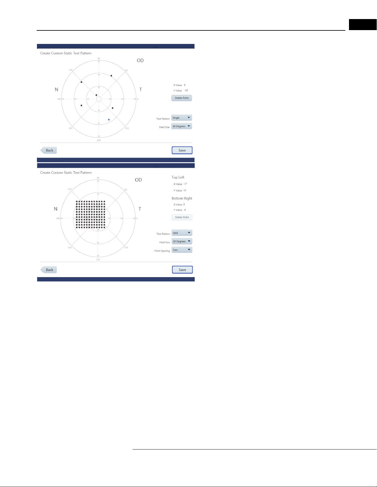
Go to Contents Setup and Testing
Create a Single Point Pattern
Set the Test Pattern to Single. Create single points by touching the
test pattern on the screen directly, or by using a mouse.
4-23
1. Move your finger or the mouse,
down, to position the point at the desired X, Y value.
2. Release your finger from the screen or mouse button to fix the
poi
nt.
Note: The new
3. Select Save when all
4. Confirm that you have entered all the points for the test.
5. Place cursor in the text box and enter a name for the pattern.
6. Select Sa
pattern.
est point created will be highlighted in blue.
the points have been created.
ve to save the pattern. Select Cancel to cancel the
while holding the mouse button
Create a Grid Point Pattern
Set the Test Pattern to Grid:
1. Position the first point with your finger or mouse and release, as
described
2. Position and fix the second point. A grid of evenly spaced points
will be
and Bottom Right points in the grid are displayed.
3. When the pattern is complete, select Save.
Note: Hig
under Top Left.
4. Confirm that you have entered all the points for the test.
5. Place cursor in the text box and enter a name for the pattern.
6. Select Sav
pattern.
The created pattern is now displayed in Custom St
drop-down menu located under Test Parameters on the Patient screen and located under Te st
Profiles in “Specific Settings,” on page 3-13.
in “Create a Single Point Pattern,” on page 4-23.
created between the two points. X, Y values of the Top Left
hlighting one of the grid points will display its X, Y values
e to save the pattern. Select Cancel to cancel the
atic Patterns, as well as the Test Patterns
Create Kinetic Test Pattern
1. S el ec t Cr
specify the right eye (OD). A mirror image of the pattern will be created for the left eye (OS).
2. Select OK.
3. Select Ye
maintain the order in which the meridians were entered.
4. Choose and add stimuli to the test pattern in the Cr
This screen has the same functionality as the Manual Kinetic Test screen. See “Administer the
Test (Manual Kinetic),” on page 4-16.
5. Select Sa
6. Select Ye
Pattern screen.
7. Enter a name for the Custom Test Pattern and select Sav
The created pattern is now displayed in C
drop-down menu located under Test Parameters on the Patient screen and located under Te st
Profiles in “Specific Settings,” on page 3-13.
HFA3 Instructions for Use 2660021166131 Rev. A 2018-11
eate Kinetic Test Pattern. A message displays stating that the pattern created will
s to randomize the order of the meridians for presentation of stimuli. Select No to
eate Custom Kinetic Test Pattern screen.
ve.
s if all points have been entered. Select No to return to the Create Custom Kinetic Test
e.
ustom Kinetic Patterns, as well as the Test Patterns
Page 70

4-24
Setup and Testing Go to Contents
Set up Test Profiles
Test Profiles comes with a standard set of tests. Test profiles can be modified or deleted except for
the 24-2 SITA Standard test and the default test.
To create a new test profile:
1. Go to Set
New Test Profile.
2. Choose the desired test parameters by using th
menus. See Appendix (A), "Test Patterns & Parameters", for further
details about test parameter settings.
Note: Once a
drop-down menu, the screen automatically displays only the options
that are available for that test type.
3. Select the Reports desired for the new test profile.
4. Enter a name and select Save to add t
located on the left-hand side of the screen.
Note: To make a test the default, highlight the test name and select Make Default. This test will now
be automatically selected when a new patient is created.
tings > Specific Settings > Test Profiles > Create
e drop-down
specific test type is selected from the Test Type
he new test profile to the list
The test is now accessible from the Test Profile menu on the Pa
tient screen.
Delete Test Profiles and Patterns
To delete a custom test profile or test pattern:
1. Go to Set
2. Hold down on the test profile or pattern to be deleted and wait for a circle to be drawn around
your finger
or
Right-click on the test profile with a mouse to bring up the pop-up menu. Select Delete.
3. A message will appear to confirm your deletion. Select Ye
tings > Specific Settings > Test Profiles
. Release your finger to bring up a pop-up menu. Select Delete.
or
Custom Test Patterns.
s or No.
HFA3 Instructions for Use 2660021166131 Rev. A 2018-11
Page 71

Quick Reference Guide
(5) Quick Reference Guide
This section is a quick reference guide for the Humphrey® Field Analyzer 3 (HFA™3).
CAUTION: Refer to the Instructions for Use for warnings, cautions, safety information,
labeling, and detailed oper
Instructions for Use.
Start Up
1. Switch the power on by pressing the On/Off button.
2. Select Continue to proceed or Details for further information.
3. Enter user name and password.
Prepare for Testing
ating instructions. The quick guide is only a complement to the
5-1
Select Patient
Step Returning Patient New Patient
1 Select the search field to display the cursor.
The sear
ch field is indicated by the icon
2 Type a few letters or numbers of any of the
following:
Date of Birth (DOB).
Select the button to initiate the search.
3 Highlight the name in the search results to
select the patien
Input Refractive Correction and Trial Lens Values
Step Returning Patient New Patient
1 The Distance Prescription and Trial Lens
values
2 If needed, change any value by touching the
value box,
value, and type a new value.
Press En
cursor to the next value box. The Trial
Lens/AutoTLC value is automatically
calculated based on the Distance Prescription
and the patient’s age.
Last or First Name, ID Number,
t from the resulting list.
are retrieved from the last test.
use the icon to delete the
ter to accept the value and move
Select the Add button.
Fill in the required entries:
Last name, First name, ID Number,
, and Date of Birth (DOB).
Gender
Patient age will appear once DOB has
been entered.
Enter the Distance Prescription values
manually.
The Trial Lens/AutoTLC value is
automatically calculated based on
Distance Prescription and the patient’s
age.
the
3 If needed, manually override the Trial Lens value by typing in
then be displayed in blue font.
HFA3 Quick Reference Guide 2660021166131 Rev. A 2018-11
the desired value, which will
Page 72

5-2
A
B
C
Quick Reference Guide
Test Se tup
1. For an existing patient the previous test that was used will automatically display.
Otherwise, the 24-2 SITA FASTER is the default test.
2. If needed, select a different test from the T
pattern, and strategy now displays.
3. If a specific test is not in the Test Profile
Test Parameters menu to select new test parameters.
est Profile menu. The new test profile,
menu, swipe down on the page and use the
4. Use the Pe
rform test on drop-down menu to select which eye to test: OD (right), OS
(left) or Both. Default is both.
5. To add notes select Add
6. Change the default Reports by selecting or deselecting one or mor
Note.
e Reports from the
drop-down menu.
7. Enter IOP (intraocular pressure) and Visual Acuity if desired.
8. Confirm test information and select the Next button to pr
Trial Lens Setup
The Auto Trial Lens Correction (AutoTLC) automatically adjusts the spherical correction to the Trial
L
ens value. This feature is only available on Model 860.
For all other models insert manual trial lens
into the holder:
oceed.
1. Move the trial lens holder into an upright position from its storage position in the
bottom of the bowl (A).
2. Place the spherical lens in the slot closest to t
he patient and the handle to the right for
the OD eye and to the left for the OS eye (B).
HFA3 Quick Reference Guide 2660021166131 Rev. A 2018-11
Page 73

Quick Reference Guide
Place chin on the appropriate side of the chin rest.
Move chair close to the instrument.
3. Place the cylinder lens, if indicated, in the slot farthest away from the patient and
align the axis (C).
Patient Setup
1. Occlude the non-test eye.
2. Position the patient. Patients are most comfortable if sitting more or less erect.
3. Instruct the patient using the instructions shown on the
screen.
5-3
Heijl, A., Patella, V.M., and Bengtsson, B. (2012) Effective Perimetry,
Fourth Edition. Carl Zeiss Meditec, Inc.
4. Touch the center of the pupil, indicated by a red X when not centered to the lens, in
the Live Eye monitor, or use the manual chin rest switch, to move the chin rest and
align the eye to the center of the lens target, indicated by a green plus sign. Pupil is
correctly centered to the lens when the plus sign (+) and the x sign (x) overlap to form
a green star ( ).
5. The Back butt
on returns to the previous screen. Select Next to proceed.
HFA3 Quick Reference Guide 2660021166131 Rev. A 2018-11
Page 74

5-4
Quick Reference Guide
Preliminary Tests (Optional)
Perform Foveal Threshold (if selected)
1. Read the on-screen instructions to the patient.
2. Select Start Foveal
3. To proceed without this test select Skip Foveal T
Threshold.
hreshold.
Perform Gaze Initialization (if selected)
1. Make sure to adjust the eye position before you initialize.
2. Read the on-screen instructions to the patient.
3. Select Start Gaz
4. To proceed without this test select Ski
5. If Gaze Initialization fails a pop-up m
e Initialization.
p Gaze Initialization.
essage provides available options.
HFA3 Quick Reference Guide 2660021166131 Rev. A 2018-11
Page 75
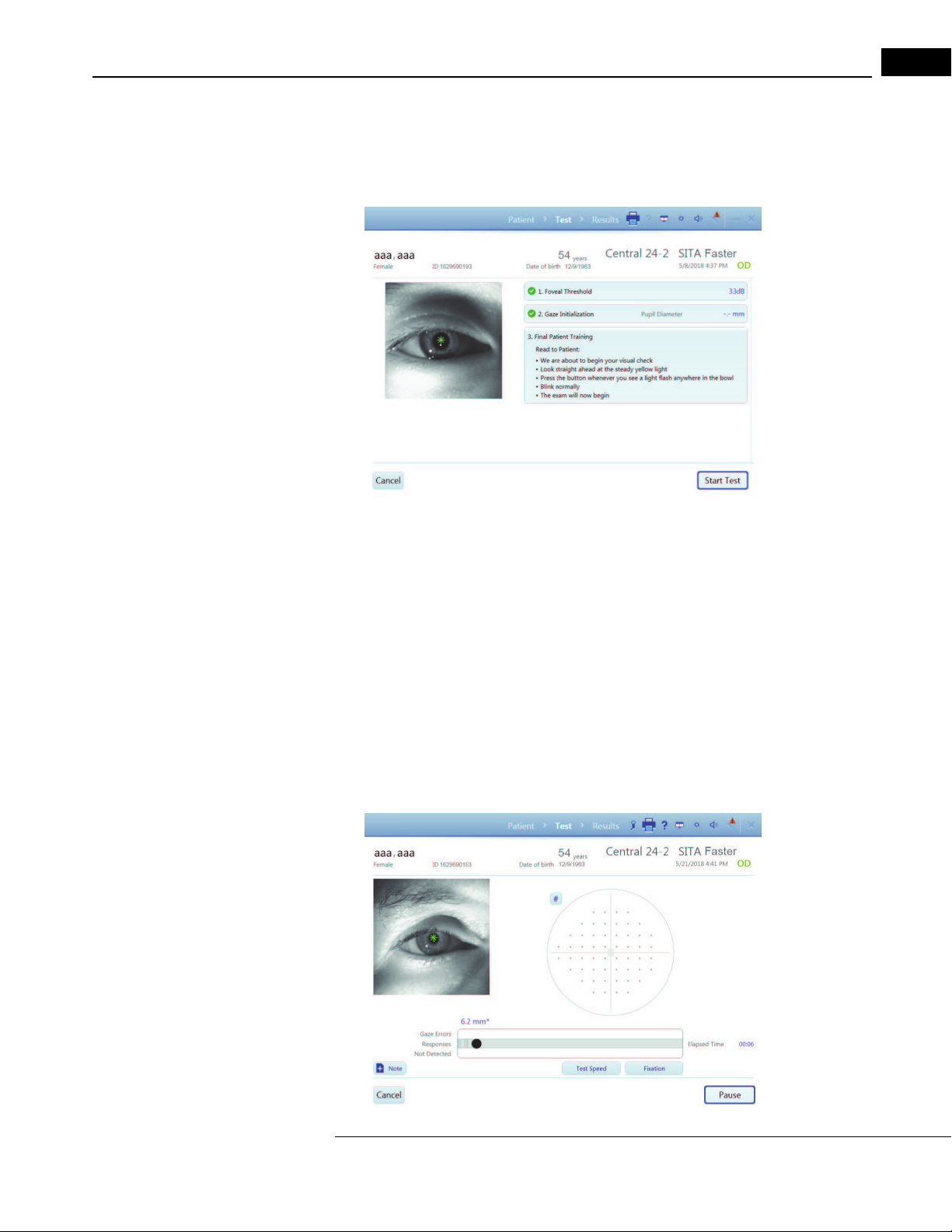
Quick Reference Guide
Perform the Test
1. R ead the Final Patient Training Instructions to the patient.
2. Select Start T
3. To cancel the test select Cancel.
est to initiate the visual field test.
5-5
Monitor the Test
Screen features:
• The Live Eye monitor allows you to center the ey
the chin rest direction controls on the instrument to manually move the chin rest. It is
recommended to leave the function Head Tracking ON and let the machine center.
• The progress bar displays patient responses, as well as gaze err
active.
• The test pattern displays closed test points in eit
• Reliability indices are shown in the upper right of the screen.
e by touching the eye image, or you can use
ors when Gaze Tracking is
her gray scale or numerical values.
1. When the test for the eye is complete, a message displays. Select OK.
2. Test the second eye following the same procedure.
HFA3 Quick Reference Guide 2660021166131 Rev. A 2018-11
Page 76

5-6
Quick Reference Guide
Review and Save Results
Review Results displays the test results for each eye tested. You can:
• Use Add Note to add comments to the exam.
• Change the output of Reports.
• Select Save and Exit. A confirmation message
1. Selected Reports will be automatically printed and/or exported based on the
configurations set for the instrument.
2. The instrument returns to the PATIENT screen.
will display when exam data is saved.
Cancel the entire exam (both tests) if you need to delete both test results and start again.
HFA3 Quick Reference Guide 2660021166131 Rev. A 2018-11
Page 77

Go to Contents Data, Tests & Reports
(6) Data, Tests & Reports
See the Instrument Settings section starting on page 3-10 to set up your instrument to backup,
archive, retrieve, and restore data.
CAUTION: Routinely back up your data in case it becomes lost or damaged.
To manage data, tests, and print reports in FORUM for a FORUM connected instrument see the user
guides for FORUM and FORUM Glaucoma Workplace. To connect the HFA3 to FORUM or EMR
systems, see Chapter (7), "Networking". T
DICOM network (Setti
DICOM EMR Settings), and the settings under DICOM Output (Settings > Specific settings > Report
Output).
ngs > Network), and turn off EMR Mode (Settings > Specific settings > Non
Save Test Reports and Test Data
The naming convention for test reports is:
Last Name_Test Date_Test Time_Eye (OD
See Tab le 6-1, Table 6-4, and Table 6-5 for the report codes.
FORUM Connected Mode
When the HFA3 is connected to FORUM, test data are
data export has been enabled (FORUM Test Database setting On under the Report Output settings).
If the connection fails, data are saved to the instrument and export continues once the connection is
re-established. If the operating mode has been changed from local database mode to FORUM
mode, transfer locally stored data to the server archive by selecting the Manual data export button
under settings in “Networking,” on page 3-19. Once records are transferred to FORUM, local data
will be deleted.
o use the instrument in local database mode, disable
or OS)_HFA serial number_Report code_Patient ID.
automatically exported to the server archive if
6-1
Local Database and EMR Connected Modes
For instruments in local database mode or connected to a DICOM compatibl
system, data are saved automatically to the HFA3. Reports selected on the Patient screen are
automatically printed and/or exported at the end of testing to the storage location configured using
the settings under Report Output or Printout. Report types for saving and printing from a patient
test list can be selected under Default Reports (see “Specific Settings,” on page 3-13).
To automatically export test r
procedures in Chapter (7), "Networking". If the connection fails to a DICOM compatible EMR,
export will continue once the connection is re-established.
eports to a DICOM compatible or non-DICOM EMR system, use the
e or non-DICOM EMR
HFA3 Instructions for Use 2660021166131 Rev. A 2018-11
Page 78

6-2
Data, Tests & Reports Go to Contents
Export Tests Manually
To manually export test data to a shared network folder or USB stor
procedure.
Note: You cannot use this procedure if data export to FORUM has been enabled (FORUM T
Database setting On under the Re
port Output settings).
1. Select the Te
(see page 1).
2. In the T
• Highlight individual tests to select a limited number of tests
to expor
• Choose Clear Select
• Select Save T
to HFAII-i Format) and save selected tests to a USB device or
network location. A data transfer summary screen will appear
with details of the export process.
sts button at the bottom of the Patient screen.
ests screen:
t, OR choose Select All to export all of the tests.
ion to clear your choice.
o (choose between Save to HFA3 Format or Save
age device, use the following
est
Save Reports Manually
You can use the following procedure to save test r
folder, or an EMR system. You cannot use this procedure if FORUM data export has been enabled.
1. Select the Re
screen.
2. In the following screen, tests for the patient will be listed.
Highlight
3. Select Sa
DICOM EMR).
4. If you selected Sa
the next screen. Choose Select if exporting to a mapped
shared folder or USB.
5. A progress screen will appear, followed by a message
stating export
Options from here are:
Select Reports - change the selection of default r
you wish to save for the selected tests.
Clear Selection - clears the highlighted
eports to a USB storage device, network shared
ports button at the bottom of the Patient
one or more tests.
ve (local database mode), DICOM EPDF (for a
ve, select/confirm the export location in
results.
eport types
tests.
HFA3 Instructions for Use 2660021166131 Rev. A 2018-11
Page 79

Go to Contents Data, Tests & Reports
6-3
Settings Option Description
Reports The list shows tests sorted on Date, Tim
Reliability. Click in the row to highlight a test. You can select one or
more tests to generate reports.
Select Reports Once the desired tests are highlighted, click on S
A menu appears at the top with the following choices (the choices vary
ing on the kind of tests that were created):
depend
• GPA-Qualified
• SFA-Qualified
• Kinetic Tests
Clear Selection Clear the selection.
Save Save selected reports.
Click on the drop-down menu and choose the format to save
reports. Format choices:
•Print
•Save
•DICOM EPDF
Back Go back to the previous screen.
e, Eye, and Parameters GPA
elect Reports.
selected
HFA3 Instructions for Use 2660021166131 Rev. A 2018-11
Page 80

6-4
Data, Tests & Reports Go to Contents
Print Test Reports
Reports selected on the Patient Test selection screen are automatically printed at the end of testing.
When a report is chosen at the P
generated at the end of the test and automatically sent to the configured output location. There is
no need to take any other action to generate the report at the end of a test.
For instruments connected to FORUM, you can print r
will be printed to a printer connected to your instrument.
Note: If the FORUM connection is lost, print reports by swit
mode. Go to Sett
connected to the instrument.
To manually print to a connected printer:
1. In the Reports screen switch the Save button
and selecting Print from the drop-down menu.
2. Touch or click on the Pr
3. A progress screen will appear, followed by a message that
ings > Network and disable DICOM network. Make sure you have a printer
int button to print the reports.
atient Test selection screen, report(s) will be automatically
eports from FORUM. For other modes, reports
ching the instrument to local database
to Print by touching or clicking the down arrow
the print process is completed.
Note: The progress screen and print complete message still appear if
turned off. When the printer is connected or turned back
the printer icon displayed at the top of the screen to display the status of the print job. Selecting the
Cancel button in the Print dialog box will not cancel the print job.
on, the queued reports will print. Select
the printer is disconnected or
Reassign Tests
If the wrong patient was selected at the beginning of a test, the test results can be reassigned to the
correct patient. This function is only available if the FORUM test database is not enabled in Specific
settings > Report Output.
1. In the P
2. Select the test to be r
3. Use the search field to find the patien
4. Select the patient and click Next.
5. Enter a reason for moving the test and click Ne
6. Confirm that the correct test is being reassigned to
atient screen, select the name of the patient that was incorrectly associated with the
test. Click the drop-down menu arrow to the right of the patient name, then select Tes ts from
the menu.
eassigned, then click Reassign.
t the test should be reassigned to.
xt. To set a default reason, select the Use this
text as default reassign reason check-box before clicking Next.
the correct patient, and select Reassign
Test.
Delete Tests
Tests can be deleted on the instrument if the FORUM test database is not enabled in Specific
settings > Report Output:
1. Sele ct t he Te
2. In the Tests screen highlight the test or tests that
3. Select De
If data are exported to FORUM, delete tests from
the instrument once they have been exported.
HFA3 Instructions for Use 2660021166131 Rev. A 2018-11
sts button on the Patient screen.
need to be deleted.
lete and confirm to delete the highlighted tests.
the archive. Tests are automatically deleted from
Page 81

Go to Contents Data, Tests & Reports
Import Tests
Test data cannot be directly imported from a DICOM/EMR system to the instrument.
Manually Import Tests
1. Connect a USB storage device containing the data you
HFA3 (see Figure 3-5). Data can also be imported
2. Go to Set
tings > Specific settings and select Import.
want transferred to a USB port on the
from a shared network folder.
6-5
3. In the Import screen, select Import.... to add the
database.database.
Note: Ther
For instruments connected to a DICOM compatible or
instrument are retained. You must manually export/import data to/from an external location to keep
multiple instruments synchronized. See “Confirm or Change Patient Information,” on page 4-2 for
more information about how patient records are reconciled.
e is no way to see or choose the tests to be imported.
tests on the storage device to the HFA3
non-DICOM EMR system, local data on the
View and Generate Test Reports
Data analysis and report generation must be conducted directly in FORUM for instruments exporting
data to FORUM.
Manually Generate Reports
When connected to an EMR system, conduct all data
using the following procedure can only be printed to a connected printer, or exported to a USB
storage device or shared network folder:
1. Highlight a patient and select the Report
2. In the following screen, tests for the patient w
Parameters, View, and GPA Reliability.
3. To view reports available for a specific test, select a test on the list.
4. A list of report types that are available for that
5. Highlight a report type. The selected report will be displayed on the screen.
Note: T
o see the available tests, select the arrow down for the report type. If no selection is
made the default selection is automatically assigned.
6. If more than one test is required for the report (lik
displays a list of qualified tests. Confirm or change which tests are included in the analysis.
Note: GP
tests. Always review the Baseline and Follow-up test selections before performing a GPA
analysis. To change the selection, deselect tests and then reselect tests to include in the
analysis. Follow-up tests cannot pre-date Baseline tests. See “GPA Analysis,” on page 6-14 for
more details. Select Ne
7. T h e Report scr
selection at the top of the page.
8. Select Bac
can be changed to Save or Save and print by selecting the down arrow and bringing up the
drop-down menu. Reports will be saved/printed in PDF format only.
A tests will display an automatic selection of qualified Baseline tests and Follow-up
xt.
een displays the report format, viewing magnification options, and printer
k to go back to the previous screen or select Print to print the report. The Print button
analysis on the instrument. Reports generated
s button at the bottom of the Patient screen.
ill be listed displaying Date, Time, Eye,
test will appear at the top of the screen.
e GPA and SFA Overview), the next screen
HFA3 Instructions for Use 2660021166131 Rev. A 2018-11
Page 82

6-6
Data, Tests & Reports Go to Contents
Merging and Deleting Patient Records
If the HFA3 is connected to an EMR system, patients merged or deleted on the HFA3 are only
merged locally; the records on the EMR remain unchanged. If the HFA3 is connected to FORUM,
patients cannot be merged or deleted from the local system because the patient database is stored
in the FORUM archive. Patient reconciliation must be done in FORUM or the leading system.
Merge Patients on the HFA3
You may merge up to 20 names into one patient file.
1. In the P
drop-down menu arrow to the right of the patient name.
Select
2. In the Merge patient data screen, en
patient records.
3. Highlight the records of interest from the resulting list.
Select
the patient record shown at the top of the screen. Original
patient record will be displayed on the right.
4. Select Mer
highlighted records with the original patient record.
5. Enter a reason for merging patient data and select Mer
again.
Where there are conflicts between an imported patient r
overwritten.
Delete Patients on the HFA3
1. In the Patient screen, select the patient, then click the drop-down menu arrow to the right of
the
patient name. Select Delete.
2. Select De
lete again to confirm.
atient screen, select the patient, then click the
Merge.
ter search terms to find
Compare to display comparisons of each record with
ge at the bottom of the screen to merge the
ecord and a local record, the local record is
ge
Static Threshold Reports
The HFA statistical software, STATPAC, provides data analysis that is included on most Threshold
report formats. STATPAC analysis is available for central field tests using the Size III, White stimulus
only. Guided Progression Analysis (GPA) helps identify progressive visual field loss in patients and is
available for Central 24-2 and Central 30-2 using the SITA Faster, SITA Fast, SITA-Standard, and Full
Threshold tests. Report examples and brief descriptions of report features are provided in the
following sections.
Report (Code) Description
Single Field Analysis (SFA) SFA analyzes the results of a single thr
most information for a given test. SFA is available for all central test
patterns regardless of test strategy.
SFA Overview (OVR) An overview report presents the results of up to sixte
tests for comparison.
Table 6-1 List of Static Threshold Reports
HFA3 Instructions for Use 2660021166131 Rev. A 2018-11
eshold test and provides the
en (16) SFA
Page 83

Go to Contents Data, Tests & Reports
Report (Code) Description
Full GPA (GPA) GPA assists with detection of glaucoma progression. Full GPA is a
multi-page overview of the patient’s entire history.
GPA Summary (GPASUM) Short GPA report (one page).
6-7
GPA Last Three Follow Up
(GPAL3F)
SFA GPA (SFAGPA) SFA GPA is an SFA report that incorporates a GPA Progression
Three In One (3N1) The Three In One report includes a gray-tone, numeric, and defect
Numeric (NUM) The Numeric Report is available for custom threshold tests and
Table 6-1 List of Static Threshold Reports
The SFA and SFA GPA Report
The SFA report displays patient data, test reliability indices, and test results in Grayscale and
Numeric formats. STATPAC analysis is found in the lower half of the page and includes the Total
Deviation Plot, the Pattern Deviation Plot, Glaucoma Hemifield Test (GHT), Visual Field Index (VFI),
Mean Deviation (MD), and Pattern Standard Deviation (PSD) values. For details see
Features,” on page 6-12.
The SFA GPA report also includes GPA results in the GPA information box (Figure 6.1). The GPA
information box contains the Progression Analysis Probability Plot for the current test, test dates for
the GPA Baseline tests and the two previous Follow-up tests, and the GPA Alert. See
Graphical GPA Plots,” on page 6-13 for further details.
Follows the same format as the Full GPA, but includes only the three
most recent Follow Up tests.
Analysis Probability Plot.
depth presentation of the results of a single test on one page, and is
available for all Threshold tests except custom and SITA-SWAP tests.
displays raw data in table format.
“Report
“Numerical and
HFA3 Instructions for Use 2660021166131 Rev. A 2018-11
Page 84

6-8
2
1
3
4
5
6
7
8
9
10
11
Data, Tests & Reports Go to Contents
cбЦмкЙ=SKN=pбеЦдЙ=cбЙдЗ=^е~дулбл=пбнЬ=dm^=Epc^=dm^F
1 – Patient Data 4 – Glaucoma Hemifield Test 7 – Grayscale Results 10 – Probability Symbols
2 – Test and Report Type 5 – Global Indices 8 – GPA Information 11 – Notes Field
3 – Reliability Indices 6 – Numeric (dB) Results 9 – Deviation Plots
HFA3 Instructions for Use 2660021166131 Rev. A 2018-11
Page 85

Go to Contents Data, Tests & Reports
1
2
4
3
The SFA Overview Report
The Overview report shows the results of multiple tests in c
and 24-2 tests may be presented in the same report.
The results of each test display Grayscale, Numeric, T
along with test date, GHT, and indices. If available, visual acuity and pupil size are located at the
upper right of each Pattern Deviation Plot.
Overview reports are available for non-STATPAC 24-2, 30-2,
plots are available. You cannot mix tests run with different stimulus sizes or colors.
hronological order. Results from 30-2
otal Deviation, and Pattern Deviation Plots,
10-2, and SWAP tests. No probability
6-9
cбЦмкЙ=SKO=pc^=lоЙкобЙп
1 – VFI 3 – Global Indices
2 – Reliability Indices 4 – Probability Symbols
HFA3 Instructions for Use 2660021166131 Rev. A 2018-11
Page 86

6-10
2
1
3
4
5
6
7
8
9
Data, Tests & Reports Go to Contents
GPA Summary Report
The GPA Summary report is a one-page report that pr
visual field history. At the top of the report, Grayscale and Pattern Deviation Plots are shown for
both GPA Baseline tests, along with key indices. The VFI Plot and VFI Bar are located in the center of
the page. Results for the current visual field test are shown at the bottom of the report, including
the Grayscale, Pattern Deviation, Deviation from Baseline, and the Progression Analysis Probability
Plots. The GPA Alert will appear here as well.
ovides an overview of the patient’s qualified
cбЦмкЙ=SKP=dm^=pмгг~ку
1 – Baseline 1 4 – VFI Plot 7 – Current Test
2 – Baseline 2 5 – VFI Bar 8 – VFI Value
3 – Indices 6 – VFI Linear Regression Analysis 9 – Progression Analysis Symbols
HFA3 Instructions for Use 2660021166131 Rev. A 2018-11
Page 87

Go to Contents Data, Tests & Reports
2
1
3 4
Full GPA and Last Three Follow Up Reports
The Full GPA report is a multi-page overview of t
provides Grayscale, Numeric, Total Deviation, and Pattern Deviation Plots, as well as key indices for
both GPA Baseline tests. The VFI Plot and Bar are displayed at the bottom. Subsequent pages show
three Follow-up tests per page in the format: Grayscale, Pattern Deviation, Deviation from Baseline,
Progression Analysis, key indices, and the GPA alert. The GPA Last Three Follow Up Report follows
the same format, but includes only the three most recent Follow-up tests.
Three in One Report
If threshold test patterns or test parameters do not meet
presented in Grayscale, Numeric, and Defect Depth formats on the Three in One report. The
numbers that appear outside each quadrant of the numeric grid are called quad totals and
represent a summation of the threshold values determined in each quadrant. This format is available
for 10-2, 24-2, 30-2 central field tests, and for the peripheral 60-4 test. The nasal step Three in One
test report displays only threshold and defect depth data.
he patient’s entire history. The Baseline page
the criteria for STATPAC analysis, results are
6-11
HFA3 Instructions for Use 2660021166131 Rev. A 2018-11
Page 88

6-12
Data, Tests & Reports Go to Contents
cбЦмкЙ=SKQ=qЬкЙЙ=fе=lеЙ
1 – Reliability Indices 3 – Defect Depth
2 – Grayscale Results 4 – Numeric (dB) Results
Report Features
Reliability Indices
Blind Spot Errors (Fixation Losses/FL)
Blind Spot Errors are recorded when Blind Spot monitoring is active and occur when a patient
r
esponds to a stimulus presented in the blind spot. The number of responses is recorded over the
total number of stimuli presented. A high error rate may mean poor patient fixation during the test
or that the blind spot was located incorrectly. Fixation Losses
False Positives (FP)
False Positive errors occur when a patient responds too quickly to a stimulus or in the absence of a
stimulus. In SITA tests False Positives are not calculated until the end of the test and a percentage
15% will be indicated by a double X. A percentage > 33% will be indicated for non-SITA tests. A
high score suggests that the patient may be overly concerned about not seeing all the stimuli.
Patients that respond inappropriately may also have abnormally high threshold results.
> 20% are indicated by a double X.
>
False Negatives (FN)
A False Negative is recorded if the patient does not respond when a stimulus is repeated at a
particular location and at a level much brighter than has already been seen.
Note: Reports will display only one message with the priority given t
message “Excessive High False Positives”. Otherwise, the message
on SITA test reports if Fixation Losses are
if either the number of Fixation Losses are
Grayscale and Numeric Formats
The Grayscale format depicts the size and depth of any
corresponds to a 5 dB change in sensitivity. The comparative scale in T
Grayscale patterns and relates them
SYM
0.8–
ASB
0.1
41–50 36–40 31–35 26–30 21–25 16–20 11–15 6–10 1–5 < 0
DB
Table 6-2 Grayscale Symbols and Numerical Equivalents in Apostilbs (ASB) and Decibels (dB).
Note: The Grayscale in SWAP printouts often looks significantly darker because SWAP testing
normally generates lower threshold sensitivity valu
maximum (0 dB) stimulus in SWAP testing is 6 foot-lamberts, not 10,000 apostilbs.
2.5–1 8–3.2 25–10 79–32 251–
> 20%. For non-SITA tests, the same message will display
> 20% or False Negatives are > 33%.
present field defects. Each pattern variation
to decibels and apostilbs.
100
es than does white-on-white testing. The
o high False Positives and the
“Low Test Reliability” is displayed
able 4-2 displays the ten (10)
794–
316
2512–
1000
7943–
3162> 10000
Total Deviation Plots
The numeric values in the upper total deviation plot represents the difference in decibels (dB)
between the patient’s test results and the age-corrected normal values at each tested point.
The lower total deviation plot, called a probability plot, tr
into shaded symbols indicating the highlights points falling below specific percentile levels
HFA3 Instructions for Use 2660021166131 Rev. A 2018-11
anslates the values from the upper plot
Page 89

Go to Contents Data, Tests & Reports
compared to the reference limits. These are explained in the legend labeled “Probability Symbols.”
For instance, a totally black square indicates that the value observed at that point location occurred
in less than 0.5% of the subjects in the reference database.
Pattern Deviation Plots
The Pattern Deviation plots are similar to the total deviation plots, except that STATPAC has adjusted
the analysis of the test results for any changes in the height of the measured hill of vision caused, for
example, by cataracts or small pupils. STATPAC also corrects for any patients who are “supernormal.”
Global Indices
6-13
Visual Field Index (VFI): VFI is a weighted aver
age-adjusted normal threshold for all points that have depressions in the Pattern Deviation at the
5% level or higher. The VFI is weighted to give increased importance to thresholds near the point of
fixation.
Mean Deviation (MD): MD is the ave
compared to the normal reference field. “P” values are given to significant deviations.
Pattern Standard Deviation (PSD): PSD is
patient’s measured field departs from the normal, age-corrected reference field. “P” values are given
to significant deviations.
Short term fluctuation (SF): SF is used with Full Thr
turned on, the threshold is measured twice at 10 preselected points. The HFA then calculates a
fluctuation value on the basis of the differences between the first and second measurements at each
of the 10 points.
Corrected Pattern Standar
is used with Full Threshold and FastPac tests only.
The Glaucoma Hemifield Test
For 24-2 and 30-2 tests, the GHT evaluates five zones in the superior field and compares these
zones to their mirr
NORMAL LIMITS, OUTSIDE NORMAL LIMITS, or BORDERLINE. The message GENERAL REDUCTION
OF SENSITIVITY is shown whenever the field is depressed to a level seen in fewer than 0.5% of the
normal population in the patient’s age range. When the comparison indicates abnormally high
sensitivity, the message ABNORMALLY HIGH SENSITIVITY appears.
d Deviation (CPSD): CPSD is PSD corrected for intra-test variability (SF) and
ored zones in the inferior field. One of these messages will be displayed: WITHIN
rage elevation or depression of the patient’s overall field
age of the ratio of the measured threshold to the
a measurement of the degree to which the shape of the
eshold and FastPac™ tests. When fluctuation is
Note: The GHT is not available with FastPac tests.
Numerical and Graphical GPA Plots
Deviation from Baseline Plot
The Deviation from Baseline Plot compares the pattern deviation of a Follow-up test to the average
of the pattern deviation values of two Baseline tests, and indicates changes at each tested point.
See Figure 6.3.
HFA3 Instructions for Use 2660021166131 Rev. A 2018-11
Page 90

6-14
Data, Tests & Reports Go to Contents
Progression Analysis Probability Plots
The Progression Analysis Probability Plot compares the changes between the Baseline and
Follow-up tests and highlights points that have worsened by an amount that exceeds the variability
in all but the most variable 5% of glaucoma patients in a reference population.
• A single, solid dot indicates a point not changing by an amoun
variability observed in a reference population.
• A small open triangle identifies a degree of deterioration expected less than 5% of the
time at that location in a reference population of stable glaucoma pat
deterioration at the 5% level (p < 0.05). This symbol is used when the change was not seen on
a pr
evious Follow-up test.
• A half-filled triangle identifies a point changing by an amount that is worse than all but the
most variable
consecutive Follow-up tests.
• A solid triangle identifies a point changing by an amount that is worse than all but the
most variable 5% of glaucoma subjects in a refer
consecutive Follow-up tests.
•An X sig
Note: Pattern Deviation plots and GPA Progression Analysis Probability plots are not shown for
severely depressed visual fields (MD less tha
5%
of glaucoma subjects in a reference population and that is repeated in two
ence population and that is repeated in three
nifies that the data at that point was out of range for analysis.
n or equal to 20 dB).
t that exceeds the test-retest
ients; that is,
VFI Plot
The VFI Plot graphs the VFI values of all tests included in GPA analysis as a function of the patient’s
age, and provides a linear regression analysis of the VFI over time (5 tests over 3 years or more are
required). VFI values from Full Threshold tests are represented by open squares, and VFI values from
SITA tests are represented by filled squares.
To the right of the VFI Plot is the VFI Bar, indicating the patien
graphically indicate the 3 to 5 year projection of the linear regression line, shown as a broken line.
The length of projection is equal to the number of years of GPA data available, up to a maximum of
5 years.
Note: GPA reports also include the GPA Alert. In cases where 3 or more points show deterioration in
at least 2 consecutive tests, the progression analysis i
where 3 or more points show deterioration in at least 3 consecutive tests, the progression analysis
indicates “Likely Progression.” When neither of the foregoing conditions applies, a message of “No
Progression Detected” is displayed.
t’s current VFI value. The VFI Bar will
ndicates “Possible Progression.” In cases
GPA Analysis
Only SITA tests may be chosen initially for GPA analysis. You may mix any combination of
SITA-Standard, SITA-Fast or SITA Faster tests to create a GPA analysis. The HFA3 will automatically
choose the two oldest compatible tests to be the Baseline. Tests displaying high False Positives ≥
15% are excluded by default from GPA analysis. You can manually change the default Baseline tests
or exclude specific tests.
HFA3 Instructions for Use 2660021166131 Rev. A 2018-11
Page 91

Go to Contents Data, Tests & Reports
Note: Manual Baseline selections may override automatic selection of the two oldest compatible
tests. Always review the Baseline and Follow-up test selections befor
the Baseline tests are Full Threshold, then the Follow-up tests may be any combination of SITA
Faster, SITA Fast, SITA-Standard, or Full Threshold. If the Baseline tests are any SITA test, then Full
Threshold are not allowed as Follow-up tests.
Suprathreshold Reports
The Suprathreshold test strategy determines the type of responses that are displayed on the report
(Table 4-3). See “Suprathreshold Test Settings,” on page A-9 for more details on Suprathreshold test
strategies.
Strategy Response Format
Two Zone Point Seen O
Point Not Seen
Three Zone Point Seen O
Relative Defects X
Absolute Defects
Quantify Defects Point Seen O
e performing a GPA analysis. If
6-15
Depth of Defect Numbers in dB (the larger the
Table 6-3 Test Response Formats
Suprathreshold reports are listed in Ta
Report (Code) Description
Suprathreshold
(SCR)
Suprathreshold OU
(SC_OU)
Report that displays a single eye. Two page
field and one displaying the central 30 degrees, are generated for the
following test patterns performed using the Quantify Defects strategy:
• Armaly Full Field
• Full Field 81 Point
• Full Field 120 Point
• Full Field 135 Point
• Full Field 246 Point
Report that displays both eyes (does not include
report is available for the following test patterns:
•Central 40 Point
• Central 64 Point
• Central 76 Point
• Central 80 Point
• Armaly Central
• Peripheral 60 Point
ble 4-4.
number the gr
reports, one displaying the full
full field patterns). This
eater the defect)
Table 6-4 List of Suprathreshold Reports
The type of test and test parameters a
test date and test time (Figure 6.5). Suprathreshold reports include the reliability indices (see
“Reliability Indices,” on page 6-12.
HFA3 Instructions for Use 2660021166131 Rev. A 2018-11
re printed at the top of the report along with the patient data,
Page 92

6-16
2
1
3
4
Data, Tests & Reports Go to Contents
When a Suprathreshold test uses the Threshold Related testing mode, the central (and peripheral)
reference level values are determined from patient responses and appear on the report. The central
reference level is the calculated threshold at the fovea. When the Age Corrected mode is used, the
central (and peripheral) reference levels display values based on the patient’s age.
cбЦмкЙ=SKR=pмйк~нЬкЙлЬздЗ=lr=oЙйзкн
1 – Eye/Test/Report 3 – Reliability Indices
2 – Test Details 4 – Response Symbols
Kinetic Reports
Report Description
Kinetic 30 Degrees
(KIN
30)
Kinetic 90 Degrees
(KIN
90)
Kinetic Table
(KIN
TBL)
Table 6-5 List of Kinetic Reports
Kinetic 90 Degrees Report
The Kinetic full field report shows all isopters mapp
hidden if they are too close together, as is likely in the central 30 degrees of the full field. The 30
degree view will display the hidden points.
Report for a central visual field test.
Report for a full visual field test.
Report that displays the locations of the starting and ending points of all
stimuli presented during the kinetic test. The table also lists all Static Points
and whether each point was seen or not.
ed out to the periphery. Some points may be
HFA3 Instructions for Use 2660021166131 Rev. A 2018-11
Page 93

Go to Contents Data, Tests & Reports
Isopters
Isopter points are connected to form the isopter lines. However, points that define the borders of a
blind spot are not connected to each other. Occasionally an isopter point will appear on the report
that is not connected to other isopter points. This situation occurs when you have retested a
meridian. Only the most recent point on a meridian will be used for the isopter map.
6-17
cбЦмкЙ=SKS=hбеЙнбЕ=VM=aЙЦкЙЙл
HFA3 Instructions for Use 2660021166131 Rev. A 2018-11
Page 94

6-18
Data, Tests & Reports Go to Contents
HFA3 Instructions for Use 2660021166131 Rev. A 2018-11
Page 95

Go to Contents Networking
(7) Networking
This chapter contains instructions for:
• Networking the HFA3.
• Connecting and exporting to a shared network folder (page 7-2 ).
• Connecting the HFA3 instrument to FORUM (page 7-4).
• Connecting the HFA3 to a DICOM compatible EMR system (page 7-5).
• Connecting the HFA3 to a non-DICOM EMR system (page 7-5).
• Configuring the instrument to use a printer.
You must log in as a user with Administr
ator privileges to access network settings.
7-1
Note: Users are responsible for network setup and
configuration of all necessary hardware and software.
network connectivity of the instrument. Customer Support cannot troubleshoot or repair problems
with network connectivity.
Note: Consult an IT, System, or
configuration information. For assistance in the U.S
contact a local ZEISS distributor.
DICOM/EMR network administrator for help in entering correct
maintenance, including installation and
ZEISS Customer Support is limited to testing
., call ZEISS at 800-341-6968. Outside the U.S.,
Network Capabilities
The HFA3 instrument can connect to local area networks for data storage using an Ethernet port.
Enable the DICOM network setting to connect to ZEISS’ FORUM or other DICOM/EMR systems.
Note: To use the instrument in local database mode,
The HFA3 supports the following:
• Store exams and reports to FORUM, or a
• Store test reports to DICOM compatible and
• Import patient scheduling and demographic informat
non-DICOM EMR system.
• Print to PostScript network printers, wireless prin
PostScript printers that are directly wired to the HFA3.
Note: The HFA3 supports Internet Protocol Version 4 (TCP/IPv4), but not IPv6.
make sure that all DICOM/EMR settings are off.
LAN (Local Area Network).
non-DICOM EMR systems.
ion from a DICOM Modality worklist or
ters (via a wireless USB adapter) and
HFA3 Instructions for Use 2660021166131 Rev. A 2018-11
Page 96

7-2
Networking Go to Contents
Configuration to Pre-existing Office Network
This section explains how to configure the HFA3 to communicate via a pre-existing office network
(LAN). To do this, the instrument must be connected to the office network by a standard network
patch cable. Make sure to plug one end of your standard network patch cable into the HFA3
Ethernet port (see Figure 3-5). Be sure to handle the cable connector gen
responsibility to install the necessary cables.
Configure Networking Settings on the HFA3
tly. It is the user’s
1.Start the instrument and log in
instrument is already on, you may log in as another user by
selecting Change user from the Close button menu while in the
P
ATIENT screen.
2. Select Setti
screen.
3. Ensure that DHCP
Enabled to automatically assign an IP address to the instrument.
4. If the network uses static IP add
administrator to have the HFA3 added, or set DHCP to Disabled
and fill in the IP Address, Subnet Mask, and Default Gateway fields.
Add Network Shared Folders
1.Make sure you are logged in as an Administrator user.
2. In the Networking scr
Network drive configuration.
3. Perform the following steps in the r
4. In N
Note: Y
directory, or a subdirectory owned by a root directory. Attempting
to map lower level folders will result in a user name and password
error message. You can navigate to lower level folders to save
reports using the Printout and Report Output settings. See
“Instrument Settings,” on page 3-10.
5. Select an unused drive letter.
6. Enter Us
enter either if no password is required.
7. Sel ect Ma
8. You will return to the Network
mapped drive appears under Available network drives.
as an Administrator user. If the
ngs > Networking to display the Networking
(Dynamic Host Configuration Protocol) is
resses, contact a network
een select Map network drive under
esulting dialog window:
etwork path, enter the network shared folder address.
ou may only map a shared folder where the target is a root
er name and Password for the shared folder. Do not
p.
ing screen. Make sure that the
HFA3 Instructions for Use 2660021166131 Rev. A 2018-11
Page 97

Go to Contents Networking
Export to a Network Shared Folder
1. S el ec t Sett
2. Select Report
3. In the E
and Print.
4. Under Report
5. Report Exp
change the export location from the Select fold
A. Choose the left folder
B. Choose the right fold
C. Choose Select.
6. You will return to the End
Patient Folders
You may also automatically create patient folders while exporting reports and XML files to a shared
network folder or USB storage device. Turn On Named Patient Folder in the End of Test Settings
screen. An automatically created patient folder name will consist of the patient’s last name, first
name, and date of birth. The patient ID will be added to the beginning of the folder name if the
appropriate setting is enabled.
ings > Specific Settings to display the Specific Settings screen (see page 13 ).
Output.
nd of Test Settings screen, under Report Output Default, select Print, Export, or Export
Export File Type select file types.
ort Location lists the current export location. Select the triple dot button to
er screen:
icon to navigate to the shared network folder. Select the mapped
folder.
er icon to add a folder to the selected export location.
of Test Settings screen.
7-3
Connect to a DICOM/EMR Server
This section contains instructions to connect the HFA3 instrument to a DICOM/EMR system
including FORUM. Once connected, the instrument can display a list of patients who are scheduled
for visual field exams from a worklist. When a patient is selected from this list, all demographic data
are entered automatically into the local HFA3 database.
Connection Settings
This section provides a description of the settings r
majority of these settings do not affect or must be disabled when connecting to a non-DICOM EMR
system (see “Connect to a Non-DICOM EMR,” on page 7-5).
Local Application Entity Settings
Station name: Typically a unique name for the exam lane or instrument. Enter a total of up to 16
characters and spaces.
AE title: En
title which needs to be registered with the DICOM system. Input a total of up to 16 characters (text
is case-sensitive).
Port: Enter the Local Port number that
Automatic MWL update: Set to Enabled
Frequency of MWL updates: If Automatic MWL update is enabled, the M
can be changed to the desired time period.
ter a unique AE title for the instrument. Each instrument must have its own unique AE
the DICOM/EMR system connects to.
to automatically update Modality Work Lists.
Remote Application Entities
MWL: Enable this service to be able to import a worklist from the DICOM/EMR system.
Storage: Allow
Query: E
Retrieve: Ena
s storage to the DICOM server.
nable this service to allow a patient search to FORUM.
ble this service to automatically retrieve patient information.
equired to connect to a DICOM/EMR system. The
odality worklist refresh rate
HFA3 Instructions for Use 2660021166131 Rev. A 2018-11
Page 98

7-4
Networking Go to Contents
Storage Commitment: Enable this service to perform a storage commitment request. This service is
used to confirm that exam data have been permanently stored by the DICOM system.
Advanced DICOM Settings
We recommend that you use the default values shown in the Specific settings dialog. Experienced
network administrators may adjust these settings to optimize performance or allow for slow network
connections.
Configure DICOM
Select Settings > Specific settings> Report Output >DICOM to
access the Additional DICOM Settings screen.
Use these settings to adjust the con
Consult your service provider for query settings that are specifically
required by your DICOM compatible system.
Include Today’s Date: I
worklist query.
Include AE Title: Includes/excludes
query.
Include Modality: Includes/excludes OPV in the worklist query.
ncludes/excludes today’s system date in the
figuration to your DICOM system.
HFA3’s AE title in the worklist
DICOM Configuration Overview
The process for a complete DICOM solution includes the following steps:
1. DI
COM Server Setup: Set up the DICOM storage to recognize the AE titles of the instruments
that will be connecting to the server. Please consult your DICOM user manual or system
administrator to configure your system.
2. N
etwork the HFA3: Configure the HFA3 instrument to connect to the network with an Ethernet
cable. See your IT administrator and“Configure Networking Settings on the HFA3,” on
page 7-2 for more information.
3. Con
figure the DICOM System: Configure your system to communicate with the designated
Storage and Modality worklist servers and perform a connection test.
4. Use DICOM: Query the Modality
and export the results back to the DICOM server.
Connect to FORUM
worklist server for scheduled exams, perform these exams,
Configure Network Settings
1. Make sure you are logged in as an Administrator user.
2. Select Sett
3. Under Connection Con
settings.
4. Enter values for Station name, AE title, and Port. Enable Automatic MWL update.
5. Configure DICOM Services aut
ings > Network to display the Network screen.
figuration, set DICOM network to Enabled to display connection
omatically or manually.
Configure DICOM Services automatically:
1. Sel ect the AutoConnect... button to display a list of detected FORUM servers.
HFA3 Instructions for Use 2660021166131 Rev. A 2018-11
Page 99

Go to Contents Networking
2. Highlight the desired server and touch or click on Select. The DICOM system’s AE title,
Host-Name, and Port will automatically populate their fields.
Configure DICOM Services manually:
1. Check the DICOM services radio button to configure MWL and Storage services only. The
Retrieve, Query, and Storage Commitment settings w
radio button unchecked if you wish to configure all services separately.
2. Highlight a service to configure from the Service
3. In the resulting dialog window, perform the following steps:
A. Enable or disable the service.
B. Enter the DICOM system’s AE title. Input a tot
case-sensitive).
C. Enter the DICOM sys
D. Enter the DICOM system’s Port number.
E. Select OK.
4. Test connections to each service by using the T
if the connection is successful.
5. Repeat steps 2.,3., and 4. for each service.
Enabled services display a check mark to the left.
tem’s Host-Name.
ill be configured from Storage. Leave the
list and select the Manual connect... button.
al of up to 16 characters (text is
est connection button. A check mark will appear
7-5
Configure Export Settings
1. S el ec t Settings > Specific settings> Report Output.
2. In the End of
enable archiving to FORUM and subsequent deletion of exam data from the instrument. Export
EPDF will be automatically disabled.
Connect to a DICOM Compatible EMR
Follow these recommended settings to connect to a
need to be configured differently depending on your system. Consult your system manual or
administrator.
Test Settings screen go to DICOM Output turn On FORUM Test Database to
DICOM compatible EMR system. Settings may
Configure Network Settings
Follow the same procedure used to connect to FORUM. Configure DICOM services manually and
make sure that MWL, Storage, and Storage Commitment are enabled. Query and Retrieve settings
do not need to be configured.
Configure Export Settings
1. S el ec t Settings > Specific settings> Report Output.
2. In the End of T
3. Turn On
Connect to a Non-DICOM EMR
Before configuring the HFA3 instrument:
• Make sure the EMR system is set up and running.
• Ensure that the HFA3 is connected to the network
Network,” on page 7-2 ).
• Configure a shared network or FTP folder on the P
Consult your IT administrator.
est Settings screen under DICOM Output turn Off FORUM Test Database.
Export EPDF to enable automatic export of EPDF at the end of testing.
(see “Configuration to Pre-existing Office
C/Server that is accessed by the EMR system.
HFA3 Instructions for Use 2660021166131 Rev. A 2018-11
Page 100

7-6
Networking Go to Contents
Configuring Export to an EMR
1. S el ec t Settings > Specific settings> Report Output.
2. In the End of T
If Forum T
Patient screen.
3. Select Sett
4. Turn on EMR Mode.
5. Under Export, select the export
est Settings screen, go to DICOM Output, and turn off Forum Test Database.
est Database is enabled, the Reports and Tes ts buttons will not be visible in the
ings > Specific Settings > Non DICOM EMR Settings.
settings.
To export to a shared folder:
A. From the Folder drop-down menu, select Sh
B. In the Net
set up on the PC/Server (see page 7-2). Select the mapped folder by
selecting the triple dot button.
C. Initiate a test connection to the HF
Test Connection on the HFA3. If you do not initiate a test on the EMR
system, the connection will fail.
D. Select the export format.
To export to an already existing FTP (File Transfer Protocol) folder:
A. Select FTP fr
B. Enter the FTP server address in FTP Server. Begin the addr
backslash at the end, or the address will be invalid.
C. Enter the folder name in the Folder field.
D. Enter User name and Password for the FTP folder.
E. Initiate a test connection to the HF
the HFA3.
F. Select the export format.
6. Under W
selection by Accession Number, Last Name, First Name, and Patient ID.
7. Map the location of the worklist, either to a shared folder or an FTP folder (see step 5).
om the Folder drop-down menu.
orklist, select the Worklist Mode. If you select Query Retrieve you can limit the
work screen, map a path to the shared folder previously
A3 on your EMR system. Select
ess with ftp://. Do not enter a
A3 on the EMR system. Then select Test Connection on
ared Folder.
Configure Network Settings
1. S el ec t Settings > Network to display the Network screen.
2. Scroll down to Connection C
3. Under Local appli
4. Under Remot
Commitment services (see steps 1, 2, and 3 in “Configure DICOM Services automatically:,” on
page 7-4).
5. Highlight the MWL service and select Manually connect...
HFA3 Instructions for Use 2660021166131 Rev. A 2018-11
cation entity, disable Automatic MWL update.
e application entity, manually disable Storage, Retrieve, Query, and Storage
onfiguration and enable DICOM network.
 Loading...