

Page 1

MC3200 INTEGRATOR
GUIDE
MN000887A03-A Dec 2018
Page 2

Page 3

Copyrights
The products described in this document may include copyrighted computer programs. Laws in the United States and
other countries preserve for certain exclusive rights for copyrighted computer programs. Accordingly, any
copyrighted computer programs contained in the products described in this document may not be copied or
reproduced in any manner without the express written permission.
©
2018 ZIH Corp and/or its affiliates. All rights reserved.
No part of this document may be reproduced, transmitted, stored in a retrieval system, or translated into any language
or computer language, in any form or by any means, without the prior written permission.
Furthermore, the purchase of our products shall not be deemed to grant either directly or by implication, estoppel or
otherwise, any license under the copyrights, patents or patent applications, except for the normal non-exclusive,
royalty-free license to use that arises by operation of law in the sale of a product.
Disclaimer
Please note that certain features, facilities, and capabilities described in this document may not be applicable to or
licensed for use on a particular system, or may be dependent upon the characteristics of a particular mobile subscriber
unit or configuration of certain parameters. Please refer to your contact for further information.
3 | Copyrights
Trademarks
Zebra and the Zebra head graphic are registered trademarks of ZIH Corp. The Symbol logo is a registered trademark
of Symbol Technologies, Inc., a Zebra Technologies company.
Page 4

Page 5

Revision History
Changes to the original guide are listed below:
Change Date Description
A01 Rev. A 6/2014 Initial release.
A02 Rev. A 3/2018 Update approved cleanser active ingredients.
5 | Revision History
A03 Rev. A 12
/2018
Add boot to accessory list.
Page 6

Page 7

Contents
Copyrights........................................................................................................................................ 3
Revision History...............................................................................................................................5
About This Guide...........................................................................................................................13
MC32N0 Series Documentation Set................................................................................................................... 13
Configurations.....................................................................................................................................................13
Chapter Descriptions........................................................................................................................................... 15
Notational Conventions.......................................................................................................................................16
Icon Conventions.................................................................................................................................................16
Related Documents..............................................................................................................................................16
Service Information.............................................................................................................................................17
Chapter 1: Getting Started....................................................................................19
Setup....................................................................................................................................................................19
Installing a microSD Card.......................................................................................................................19
Installing the MC32N0-G Battery...........................................................................................................20
Installing the MC32N0–R/S Battery....................................................................................................... 22
Charging the Battery............................................................................................................................... 23
Resetting the Android Device............................................................................................................................. 24
Performing a Soft Reset.......................................................................................................................... 24
Performing a Hard Reset......................................................................................................................... 24
Performing an Enterprise Reset...............................................................................................................25
Performing a Factory Reset.....................................................................................................................26
Resetting the WinCE Device...............................................................................................................................27
Performing a Warm Boot........................................................................................................................ 27
Performing a Cold Boot.......................................................................................................................... 27
Contents | 7
Chapter 2: Accessories...........................................................................................29
MC32N0 Accessories..........................................................................................................................................29
Battery Adapter................................................................................................................................................... 32
Installing the Battery Adapter................................................................................................................. 32
Removing the Battery Adapter................................................................................................................33
Single Slot Serial/USB Cradle............................................................................................................................ 34
Setup........................................................................................................................................................35
Charging the MC32N0 Battery............................................................................................................... 35
Charging an MC32N0 Spare Battery...................................................................................................... 36
Battery Charging in Single Slot Serial/USB Cradle................................................................................37
Four Slot Charge Only Cradle.............................................................................................................................38
Setup........................................................................................................................................................38
Charging the MC32N0 Battery............................................................................................................... 39
Battery Charging in the Four Slot Charge Only Cradle.......................................................................... 39
Four Slot Ethernet Cradle....................................................................................................................................39
LED Indicators........................................................................................................................................ 40
CRD3X01-4001ER Setup....................................................................................................................... 40
Daisychaining Ethernet Cradles.................................................................................................. 41
Ethernet Settings on Android Devices........................................................................................ 41
Ethernet Settings on WinCE Devices..........................................................................................43
Charging the MC32N0 Battery............................................................................................................... 44
Battery Charging in the Four Slot Ethernet Cradle................................................................................. 44
Four Slot Spare Battery Charger......................................................................................................................... 44
Page 8

8 | Contents
Setup........................................................................................................................................................45
Charging Spare Batteries.........................................................................................................................45
Battery Charging..................................................................................................................................... 46
Universal Battery Charger Adapter.....................................................................................................................47
Setup........................................................................................................................................................47
Charging a Spare Battery in the UBC Adapter....................................................................................... 47
UBC Adapter Battery Charging.............................................................................................................. 48
Wall Mount Bracket............................................................................................................................................ 49
Mounting a Four Slot Cradle...................................................................................................................49
MC32N0–G Handstrap Replacement..................................................................................................................50
MC32N0–S/R Handstrap Replacement...............................................................................................................52
Chapter 3: USB Communication..........................................................................55
Connecting to a Host Computer via USB........................................................................................................... 55
Connecting to the MC32N0 as a Media Device......................................................................................55
Connecting to the MC32N0 as an Installer............................................................................................. 55
Disconnect from the Host Computer...................................................................................................................56
Chapter 4: DataWedge Configuration................................................................. 57
Basic Scanning.................................................................................................................................................... 57
Using the Imager..................................................................................................................................... 57
Using the Laser Scanner..........................................................................................................................58
Profiles.................................................................................................................................................................58
Plug-ins................................................................................................................................................................59
Profiles Screen.....................................................................................................................................................60
Disabling DataWedge..............................................................................................................................61
Creating a New Profile........................................................................................................................................62
Profile Configuration...........................................................................................................................................62
Bar Code Input........................................................................................................................................ 63
MSR Input............................................................................................................................................... 69
Keystroke Output.................................................................................................................................... 70
Intent Output............................................................................................................................................70
Intent Overview...........................................................................................................................71
IP Output................................................................................................................................................. 72
Using IP Output with IPWedge...................................................................................................73
Using IP Output without IPWedge..............................................................................................74
Generating Advanced Data Formatting Rules.....................................................................................................75
Configuring ADF Plug-in........................................................................................................................75
Creating a Rule............................................................................................................................76
Defining a Rule........................................................................................................................... 76
Defining Criteria..........................................................................................................................77
Defining an Action...................................................................................................................... 78
Deleting a Rule............................................................................................................................78
Order Rules List.......................................................................................................................... 78
ADF Example..............................................................................................................................79
DataWedge Settings............................................................................................................................................ 82
Importing a Configuration File................................................................................................................82
Exporting a Configuration File................................................................................................................83
Importing a Profile File........................................................................................................................... 83
Exporting a Profile.................................................................................................................................. 83
Restoring DataWedge..............................................................................................................................84
Configuration and Profile File Management.......................................................................................................84
Programming Notes.............................................................................................................................................85
Overriding Trigger Key in an Application.............................................................................................. 85
Page 9

Contents | 9
Capture Data and Taking a Photo in the Same Application....................................................................85
Disable DataWedge on MC32N0 and Mass Deploy...............................................................................85
Soft Scan Feature.....................................................................................................................................85
Chapter 5: Administrator Utilities....................................................................... 87
Required Software...............................................................................................................................................87
On-device Application Installation..................................................................................................................... 87
Multi-user/AppLock Configuration.................................................................................................................... 87
Enterprise Administrator Application................................................................................................................. 88
Creating Users......................................................................................................................................... 88
Adding Packages..................................................................................................................................... 89
Creating Groups...................................................................................................................................... 90
Creating Remote Authentication.............................................................................................................90
Save Data.................................................................................................................................................91
Exporting File..........................................................................................................................................91
Importing User List................................................................................................................................. 91
Importing Group List...............................................................................................................................92
Importing Package List........................................................................................................................... 92
Editing a User..........................................................................................................................................92
Deleting a User........................................................................................................................................92
Editing a Group....................................................................................................................................... 92
Deleting a Group..................................................................................................................................... 92
Editing a Package.................................................................................................................................... 93
Deleting a Package.................................................................................................................................. 93
MultiUser Administrator..................................................................................................................................... 93
Importing a Password..............................................................................................................................93
Disabling the Multi-user Feature.............................................................................................................94
Enabling Remote Authentication............................................................................................................ 94
Disabling Remote Authentication........................................................................................................... 95
Enabling Data Separation........................................................................................................................95
Disabling Data Separation.......................................................................................................................95
Delete User Data..................................................................................................................................... 96
Capturing a Log File................................................................................................................................96
AppLock Administrator...................................................................................................................................... 96
Enabling Application Lock..................................................................................................................... 96
Disabling Application Lock.................................................................................................................... 97
Manual File Configuration.................................................................................................................................. 97
Groups File..............................................................................................................................................98
White List File.........................................................................................................................................99
Determining Applications Installed on the Device............................................................................... 100
Package List File................................................................................................................................... 100
Secure Storage...................................................................................................................................................100
Installing a Key..................................................................................................................................... 100
Viewing Key List.................................................................................................................................. 101
Deleting a Key.......................................................................................................................................101
Volumes.................................................................................................................................................102
Creating Volume Using EFS File..............................................................................................102
Creating a Volume Manually.................................................................................................... 102
Mounting a Volume...................................................................................................................103
Listing Volumes........................................................................................................................ 103
Unmounting a Volume.............................................................................................................. 103
Deleting a Volume.....................................................................................................................103
Encrypting an SD Card..............................................................................................................103
Creating an EFS File............................................................................................................................. 103
Off-line Extraction Tool........................................................................................................................104
Page 10

10 | Contents
Usage.........................................................................................................................................104
Creating an Image..................................................................................................................... 104
Mounting an Image................................................................................................................... 105
Unmounting an Image...............................................................................................................105
Chapter 6: Settings for Android Devices........................................................... 107
Location Settings...............................................................................................................................................107
Screen Unlock Settings..................................................................................................................................... 107
Single User Mode..................................................................................................................................108
Set Screen Unlock Using PIN................................................................................................... 108
Set Screen Unlock Using Password.......................................................................................... 109
Multiple User Mode.............................................................................................................................. 109
Passwords.......................................................................................................................................................... 109
Button Remapping.............................................................................................................................................109
Remapping a Button..............................................................................................................................110
Exporting a Configuration File..............................................................................................................111
Importing a Configuration File..............................................................................................................111
Creating a Remap File...........................................................................................................................112
Enable Key Wakeup..............................................................................................................................113
Accounts............................................................................................................................................................114
Language Usage................................................................................................................................................ 114
Changing the Language Setting............................................................................................................ 114
Adding Words to the Dictionary........................................................................................................... 114
Keyboard Settings............................................................................................................................................. 114
About Device.....................................................................................................................................................114
Chapter 7: Application Deployment for Android Devices............................... 117
Security..............................................................................................................................................................117
Secure Certificates.................................................................................................................................117
Installing a Secure Certificate............................................................................................................... 117
Configuring Credential Storage Settings...............................................................................................117
Development Tools........................................................................................................................................... 118
ADB USB Setup................................................................................................................................................118
Application Installation..................................................................................................................................... 119
Installing Applications Using the USB Connection..............................................................................119
Installing Applications Using the Android Debug Bridge.................................................................... 119
Installing Applications Using a microSD Card.....................................................................................120
Uninstalling an Application...................................................................................................................121
Updating the MC32N0 System......................................................................................................................... 121
Storage...............................................................................................................................................................122
Random Access Memory...................................................................................................................... 122
External Storage.................................................................................................................................... 123
Internal Storage..................................................................................................................................... 124
Enterprise Folder................................................................................................................................... 124
Application Management.................................................................................................................................. 124
Viewing Application Details.................................................................................................................125
Stopping an Application........................................................................................................................126
Changing Application Location............................................................................................................ 126
Managing Downloads............................................................................................................................127
Chapter 8: Synchronization................................................................................ 129
Installing the Sync Software..............................................................................................................................129
Mobile Computer Setup.................................................................................................................................... 129
Page 11

Contents | 11
Setting Up a Connection Using ActiveSync..................................................................................................... 130
Setting Up a Connection Using WMDC........................................................................................................... 131
Setting up a Partnership.....................................................................................................................................132
Chapter 9: Settings for WinCE Devices.............................................................135
Interactive Sensor Technology Configuration.................................................................................................. 135
Display Tab........................................................................................................................................... 135
Power Management Tab........................................................................................................................135
Events Tab.............................................................................................................................................137
Sensors Tab........................................................................................................................................... 137
IST Info................................................................................................................................................. 139
Wakeup Conditions........................................................................................................................................... 139
Battery Usage Threshold Setting.......................................................................................................................140
Bluetooth Configuration Setting....................................................................................................................... 142
Sample Applications and StartUpCtl Configuration.........................................................................................142
Chapter 10: Application Deployment for Windows CE...................................145
Windows CE Flash Storage...............................................................................................................................146
Deployment....................................................................................................................................................... 148
Copying Files from a Host Computer................................................................................................... 149
ActiveSync................................................................................................................................ 149
Mass Storage............................................................................................................................. 150
Updating Images....................................................................................................................................151
OS Update Loader.....................................................................................................................151
Bootloader................................................................................................................................. 151
Creating a Splash Screen...................................................................................................................................157
Loading a Splash Screen................................................................................................................................... 157
Chapter 11: Maintenance and Troubleshooting............................................... 159
Maintaining the MC32N0................................................................................................................................. 159
Battery Safety Guidelines..................................................................................................................................159
Cleaning Instructions.........................................................................................................................................160
Cleaning the MC32N0...........................................................................................................................161
Housing..................................................................................................................................... 161
Display.......................................................................................................................................161
Camera Window........................................................................................................................161
Connector Cleaning...................................................................................................................161
Cleaning Cradle Connectors..................................................................................................................162
Troubleshooting.................................................................................................................................................162
Troubleshooting the MC32N0...............................................................................................................162
Single Slot Serial/USB Cradle Troubleshooting...................................................................................164
Four Slot Charge Only Cradle CRD3000–4000CR Troubleshooting...................................................165
Four Slot Ethernet Cradle CRD3X01–4001ER.....................................................................................166
Four Slot Battery Charger SAC7X00-4000R Troubleshooting............................................................ 166
Cables.................................................................................................................................................... 167
Chapter 12: Technical Specifications................................................................. 169
MC32N0 Technical Specifications................................................................................................................... 169
SE965 Decode Zone..............................................................................................................................172
SE4750-SR Decode Zone......................................................................................................................173
MC32N0 Connector Pin-Out.................................................................................................................174
MC32N0 Accessory Specifications...................................................................................................................175
Page 12

12 | Contents
Single Slot Serial/USB Cradle CRD3000-1001R Technical Specifications.........................................175
Four Slot Charge Only Cradle CHS3000-4001CR Technical Specifications.......................................176
Four Slot Ethernet Cradle CRD30X01-4001ER Technical Specifications...........................................176
Four Slot Battery Charger SAC7X00-4000CR Technical Specifications.............................................177
Chapter 13: Keypad Remap Strings.................................................................. 179
Keypad Remap Strings......................................................................................................................................179
Page 13

About This Guide
This guide provides information about using the MC32N0 Series of mobile computers and accessories.
Note: Screens and windows pictured in this guide are samples and can differ from actual screens.
MC32N0 Series Documentation Set
The documentation set for the MC32N0 Series provides information for specific user needs, and includes:
• MC32N0 Quick Start Guide - describes how to get the device up and running.
• MC32N0 Regulatory Guide - provides required regulatory information.
• MC32N0 User Guide - describes how to use the device.
• MC32N0 Integrator Guide - describes how to set up the device and accessories.
13 | About This Guide
Configurations
This guide covers the following configurations:
Configuration Radios Display Memory
MC32N0–G Standard
MC32N0–G Premium
MC32N0–R Standard
WLAN:
802.11a/b/g/n
WPAN: Bluetooth v2.1 with
EDR
WLAN:
802.11a/b/g/n
WPAN: Bluetooth v2.1 with
EDR
WLAN:
802.11a/b/g/n
WPAN: Bluetooth v2.1 with
EDR
3.0” color 512 MB RAM /
3.0” color 1 GB RAM / 4
3.0” color 512 MB RAM /
2 GB Flash
GB Flash
2 GB Flash
Data Capture
Options
Imager or laser
scanner
Imager or laser
scanner, Interactive Sensor
Technology
(IST)
Laser scanner Windows CE
Operating
System
Windows CE
7.0
Android-based,
Android OpenSource Project
4.1.1 or Windows CE 7.0
7.0
MC32N0–R Premium
WLAN:
802.11a/b/g/n
WPAN: Bluetooth v2.1 with
EDR
3.0” color 1 GB RAM / 4
GB Flash
Laser scanner,
IST
Android-based,
Android OpenSource Project
4.1.1 or Windows CE 7.0
Table continued…
Page 14
14 | About This Guide
Configuration Radios Display Memory
MC32N0–S Standard
MC32N0–S Premium
WLAN:
802.11a/b/g/n
WPAN: Bluetooth v2.1 with
EDR
WLAN:
802.11a/b/g/n
WPAN: Bluetooth v2.1 with
EDR
3.0” color 512 MB RAM /
2 GB Flash
3.0” color 1 GB RAM / 4
GB Flash
Software Versions for Android
To determine the current software versions touch > About device.
• Serial number – Displays the serial number.
• Model number – Displays the model number.
• Android version – Displays the operating system version.
• Kernel version – Displays the kernel version number.
• Build number – Displays the software build number.
Data Capture
Options
Imager or laser
scanner
Imager or laser
scanner, IST
Operating
System
Windows CE
7.0
Android-based,
Android OpenSource Project
4.1.1 or Windows CE 7.0
Software Versions for WinCE
This guide covers various software configurations and references are made to operating system or software versions
for:
• OEM version
• BTExplorer version
• Fusion version.
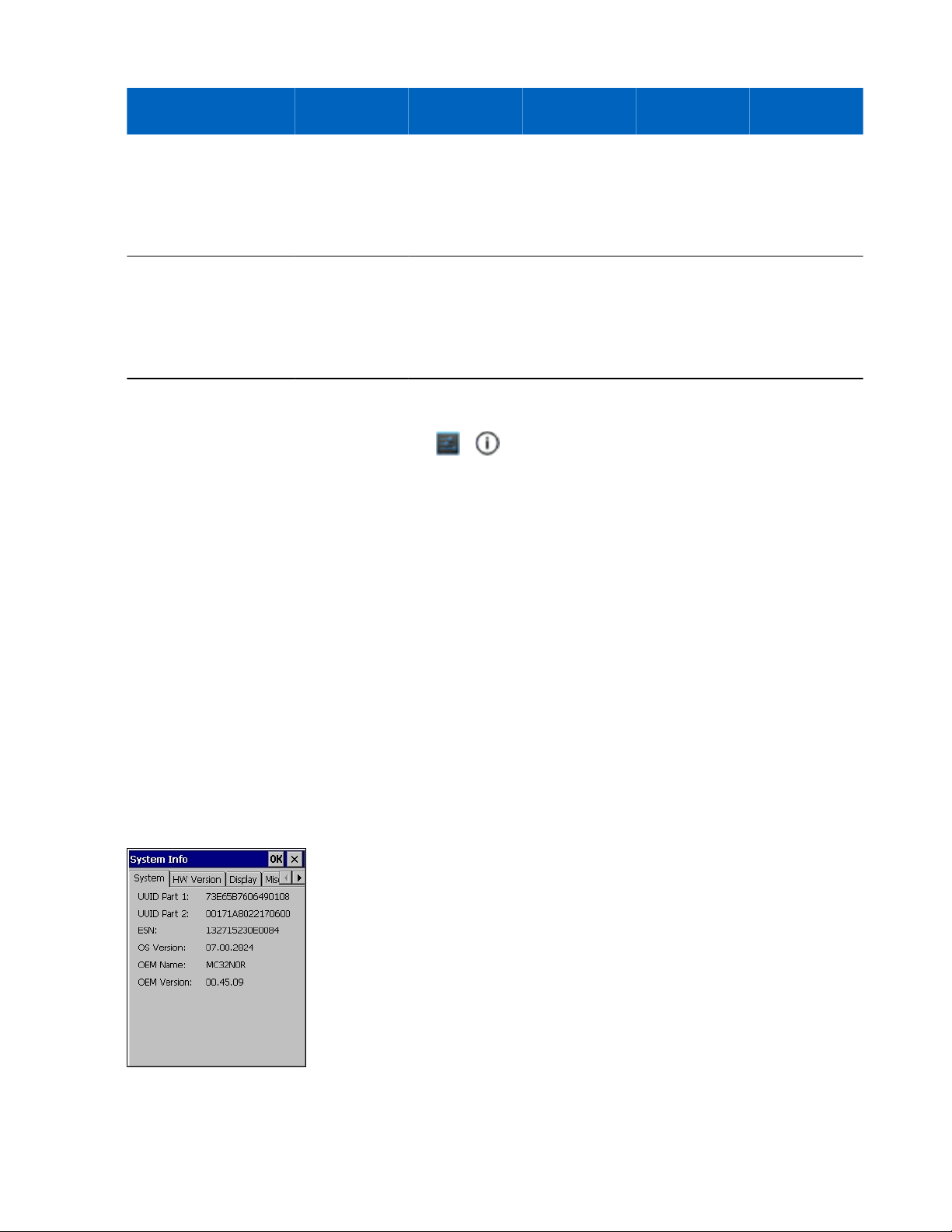
OEM Version
To determine the OEM software version tap Start > Settings > Control Panel > System Info icon > System tab.
Figure 1: System Info – OEM Version
Page 15
About This Guide | 15
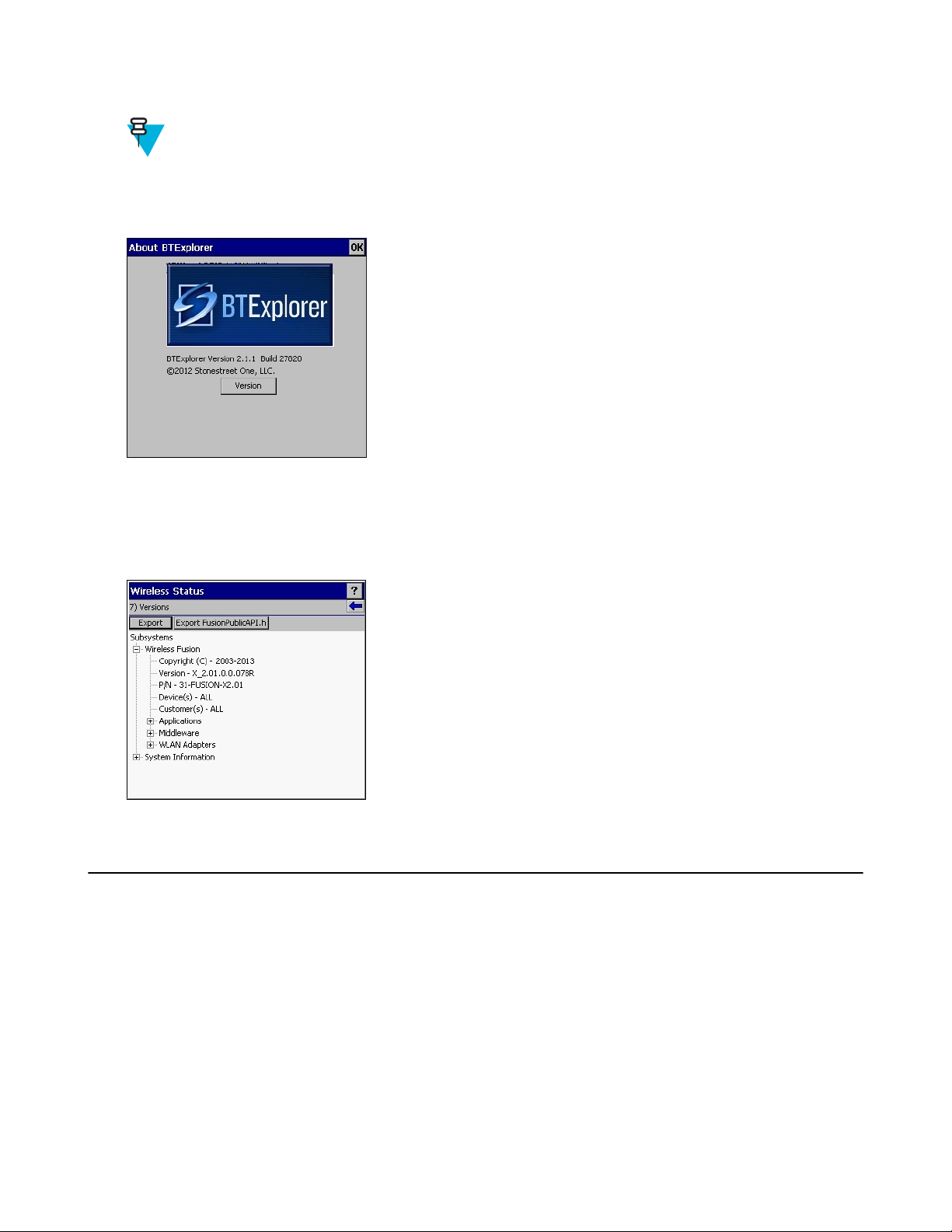
BTExplorer Software
Note: StoneStreet Bluetooth stack has to be enabled to see version number.
To determine the BTExplorer software version tap BTExplorer icon > Show BTExplorer > File > About.
Figure 2: BTExplorer Version
Fusion Software
To determine the Fusion software version tap Wireless Strength icon > Wireless Status > Versions.
Figure 3: Fusion Version
Chapter Descriptions
Topics covered in this guide are as follows:
• Getting Started
• Accessories on page 29 describes the available accessories and how to use them with the MC32N0.
• USB Communication on page 55 describes how to connect the MC32N0 to a host computer using USB.
• DataWedge Configuration on page 57 describes how to use and configure the DataWedge application.
• Administrator Utilities on page 87 provides information for using the suite of administrative tools for
configuring the MC32N0.
• Settings for Android Devices on page 107 provides the settings for configuring the MC32N0 with Android.
• Application Deployment for Android Devices on page 117 provides information for developing and managing
applications with Android.
on page 19 provides information on getting the MC32N0 up and running for the first time.
Page 16

16 | About This Guide
• Synchronization on page 129 provides instructions on installing ActiveSync, setting up a partnership and
synchronizing information between the MC32N0 and a host computer.
• Settings for WinCE Devices
• Application Deployment for Windows CE on page 145 provides information for developing and managing
applications with WinCE.
• Maintenance and Troubleshooting on page 159 includes instructions on cleaning and storing the MC32N0, and
provides troubleshooting solutions for potential problems during MC32N0 operation.
• Technical Specifications on page 169 provides the technical specifications for the MC32N0.
on page 135 provides the settings for configuring the MC32N0 with WinCE.
Notational Conventions
The following conventions are used in this document:
• Italics are used to highlight the following:
Chapters and sections in this and related documents
-
- Icons on a screen.
• Bold text is used to highlight the following:
- Dialog box, window, and screen names
- Drop-down list and list box names
- Check box and radio button names
- Button names on a screen.
• Bullets (•) indicate:
- Action items
- Lists of alternatives
- Lists of required steps that are not necessarily sequential
• Sequential lists (for example, lists that describe step-by-step procedures) appear as numbered lists.
Icon Conventions
The documentation set is designed to give the reader more visual clues. The following graphic icons are used
throughout the documentation set. These icons and their associated meanings are described below.
Warning: The word WARNING with the associated safety icon implies information that, if disregarded,
could result in death or serious injury, or serious product damage.
Caution: The word CAUTION with the associated safety icon implies information that, if disregarded,
may result in minor or moderate injury, or serious product damage.
Note: NOTE contains information more important than the surrounding text, such as exceptions or
preconditions. They also refer the reader elsewhere for additional information, remind the reader how to
complete an action (when it is not part of the current procedure, for instance), or tell the reader where
something is located on the screen. There is no warning level associated with a note.
Related Documents
• MC32N0 Quick Start Guide, p/n MN000215Axx
• MC32N0 Regulatory Guide, p/n MN000216Axx
• MC32N0 User Guide, p/n MN000886Axx
Page 17

About This Guide | 17
For the latest version of this guide and all guides, go to: http://www.zebra.com/support.
Service Information
If you have a problem with your equipment, contact Zebra Support Center for your region. Contact information is
available at: http://www.zebra.com/support.
When contacting the Zebra Support Center, please have the following information available:
Serial number of the unit (found on manufacturing label)
•
• Model number or product name (found on manufacturing label)
• Software type and version number
Figure 4: Manufacturing Label Location
Zebra responds to calls by email or telephone within the time limits set forth in support agreements.
If your problem cannot be solved by the Zebra Support Center, you may need to return your equipment for servicing
and will be given specific directions. Zebra is not responsible for any damages incurred during shipment if the
approved shipping container is not used. Shipping the units improperly can possibly void the warranty.
If you purchased your product from a Zebra business partner, contact that business partner for support.
Page 18

Page 19

Chapter
1
Getting Started
This chapter provides information for getting the device up and running for the first time.
Setup
To start using the MC32N0 for the first time:
Install a microSD card (optional)
•
• Install the battery
• Charge the MC32N0
• Power on the MC32N0.
19 | Getting Started
Installing a microSD Card
The microSD card slot provides secondary non-volatile storage. The slot is located under the battery pack. Refer to
the documentation provided with the card for more information, and follow the manufacturer’s recommendations for
use.
Caution: Follow proper electrostatic discharge (ESD) precautions to avoid damaging the microSD card.
Proper ESD precautions include, but are not limited to, working on an ESD mat and ensuring that the
operator is properly grounded.
Note: On Android devices, after installing the microSD card, the device will automatically reset. This
ensures proper reading of the file content on the microSD card.
Procedure:
1 Remove the microSD card cover.
Figure 5: Remove microSD Card Cover
2 Slide the microSD card holder down to unlock.
Page 20

20 | Getting Started
Figure 6: Unlock microSD Card Holder
3 Lift the microSD card holder.
Figure 7: Lift microSD Card Holder
4 Place the microSD card into the contact area.
Figure 8: Install microSD Card
5 Close the microSD card holder and slide the microSD card holder up to lock.
Figure 9: Lock microSD Card Holder
6 Replace the microSD card cover and ensure that it is installed properly.
Installing the MC32N0-G Battery
To install the battery:
Procedure:
1 Align the battery into the battery compartment.
Page 21

Figure 10: Inserting the Battery
Getting Started | 21
2 Rotate the bottom of the bottom into the battery compartment.
3 Press battery down firmly. Ensure that both battery release buttons on the sides of the MC32N0 return to the home
position.
Figure 11: Press Battery Down
4 Press the Power button to turn on the device.
5 On WinCE device with Rev B software, after boot up the calibration screen appears. Using the stylus, touch the
targets as they appear on the screen.
Page 22

22 | Getting Started
Installing the MC32N0–R/S Battery
Procedure:
1 Loosen the handstrap.
2 Align the top of the battery into the battery compartment.
Figure 12: Inserting the Battery
3 Rotate the bottom of the bottom into the battery compartment.
4 Press battery down firmly. Ensure that both battery release buttons on the sides of the MC32N0 return to the home
position.
Figure 13: Press Battery Down
5 Tighten the handstrap.
6 Press the Power button to turn on the device.
Page 23

Getting Started | 23
7 On WinCE device with Rev B software, after boot up the calibration screen appears. Using the stylus, touch the
targets as they appear on the screen.
Charging the Battery
Caution: Ensure that you follow the
page 159.
Use the mobile computer cradles, cables and spare battery chargers to charge the mobile computer main battery.
The main battery can be charged before insertion into the mobile computer or after it is installed.
batteries for the MC32N0, the Standard Battery (1X) and the Extended Life Battery (2X). The standard capacity
battery ships from the factory in all MC32N0-R configurations. The Extended Life Battery ships from the factory in
all MC32N0-S and MC32N0-G configurations. To install an Extended Life Battery in the MC32N0-R configurations,
purchase an Extended Life Battery. Use one of the spare battery chargers to charge the main battery (out of the mobile
computer) or one of the cradles to charge the main battery while it is installed in the mobile computer.
Before using the mobile computer for the first time, fully charge the main battery until the amber Charge LED
Indicator remains lit (see Table 1: LED Charge Indicators on page 23 for charge status indications). The Standard
Battery fully charges in less than five hours and the Extended Life Battery fully charges in less than eight hours.
The MC32N0 retains data in memory for at least five minutes when the mobile computer’s main battery is removed
or fully discharged.
When the main battery reaches a very low battery state, the battery retains data in memory for at least 36 hours.
Batteries must be charged within the 0° to +40° C (32° to 104° F) ambient temperature range.
The following accessories can be used to charge batteries:
• Cradles (and a power supply):
- Single Slot Serial/USB Cradle with Battery Adapter
- Four Slot Cradles.
• Cables (and a power supply):
guidelines for battery safety described in Battery Safety Guidelines on
There are two main
- USB Client Charge Cable
- Serial (RS232) Charge Cable.
• Spare Battery Chargers (and a power supply):
- Four Slot Spare Battery Charger
- Universal Battery Charger (UBC) Adapter with Battery Adapter.
To charge the mobile computer using the cradles:
1. Insert the mobile computer into a cradle. See Accessories on page 29 for accessory setup.
2. The mobile computer starts to charge automatically. The amber Charge LED Indicator indicates the charge status.
See the table below for charging indications.
To charge the mobile computer using the cables:
1. Connect the MC32N0 Communication/Charge Cable to the appropriate power source and connect to the mobile
computer. See Accessories on page 29 for accessory setup.
2. The mobile computer starts to charge automatically. The amber Charge LED Indicator indicates the charge status.
Table 1: LED Charge Indicators
Status Indications
Off
MC32N0 is not charging.
Table continued…
Page 24

24 | Getting Started
Status Indications
MC32N0 is not inserted correctly in the cradle.
MC32N0 is not connected to a power source.
Charger or cradle is not powered.
Slow Blinking Amber MC32N0 is charging.
Solid Amber Charging complete. Note: When the battery is initially inserted in the mobile
computer, the amber LED flashes once if the battery power is low.
Fast Blinking Amber Charging error, e.g.:
Temperature is too low or too high.
•
• Charging has gone on too long without completion (typically eight hours).
Charging Temperature
Charge batteries in ambient temperatures from 0 °C to 40 °C (32 °F to 104 °F) or up to 45 °C (113 °F) as reported by
the battery. To view the battery temperature on Android devices, touch the Battery Info icon on the Home screen or
touch > About device > Battery Information.
Note that charging is intelligently controlled by the MC32N0. To accomplish this, for small periods of time, the
MC32N0 or accessory alternately enables and disables battery charging to keep the battery at acceptable
temperatures. The MC32N0 or accessory indicates when charging is disabled due to abnormal temperatures via its
LED.
Charging Spare Batteries
See Accessories on page
29 for information on using accessories to charge spare batteries.
Resetting the Android Device
There are two reset functions, soft reset and hard reset.
Performing a Soft Reset
Perform a soft reset if applications stop responding.
Procedure:
1 Press and hold the Power button until the menu appears.
2 Touch Reset.
3 The device reboots.
Performing a Hard Reset
Note: All un-saved data is lost after performing a Hard Reset.
Perform a Hard Reset if the device stops responding. To perform a Hard Reset:
Procedure:
1 Simultaneously press the Power button, 1 and 9 keys.
Page 25

Getting Started | 25
2 The device reboots.
Performing an Enterprise Reset
An Enterprise Reset erases all data in the /cache and /data partitions and clears all device settings, except those
in the /enterprise partition.
Before performing an Enterprise Reset, copy all applications and the key remap configuration file that you want to
persist after the reset into the /enterprise/usr/persist folder.
Procedure:
1 Download the Enterprise Reset file from the Zebra web site, http://www.zebra.com/support.
2 Copy the M32N0JXXRExxxxxxx.zip file to the root directory of the microSD card. See USB Communication
on page 55.
3 Press and hold the Power button until the menu appears.
4 Touch Reset.
5 On the MC32N0–G device, press and hold the Trigger button or on the MC32N0–R/S devices, press and hold the
Right Scan button..
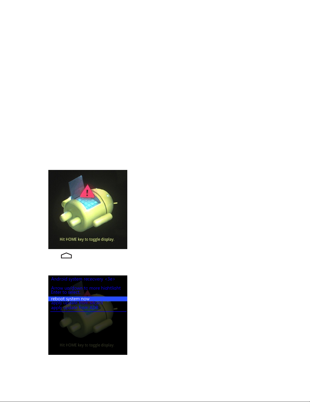
6 When the Recovery Mode screen appears, release the button.
Figure 14: Recovery Mode Screen
7
Press . The System Recovery screen appears.
Figure 15: System Recovery Screen
8 Use the navigation keys to navigate to the apply update from sdcard option.
9 Press Enter.
Page 26
26 | Getting Started
10 Use the navigation keys to navigate to the M32N0JXXRExxxxx.zip file.
11 Press Enter. The Enterprise Reset occurs and then the device resets.
Performing a Factory Reset
A Factory Reset erases all data in the /cache, /data and /enterprise partitions in internal storage and clears all device
settings. A Factory Reset returns the device to the last installed operating system image. To revert to a previous
operating system version, re-install that operating system image. See Updating the MC32N0 System
more information.
Procedure:
1 Download the Factory Reset file from the Zebra web site, http://www.zebra.com/support.
2 Copy the M32N0JXXRFxxxxxxx.zip file to the root directory of the microSD card. See USB Communication
on page 55.
3 Press and hold the Power button until the menu appears.
4 Touch Reset.
5 On the MC32N0–G device, press and hold the Trigger button or on the MC32N0–R/S devices, press and hold the
Right Scan button..
6 When the Recovery Mode screen appears release the button.
on page 121 for
Figure 16: Recovery Mode Screen
7
Press .
Figure 17: System Recovery Screen
8 Use the navigation keys to navigate to the apply update from sdcard option.
9 Press Enter.
Page 27

Getting Started | 27
10 Use the navigation keys to navigate to the M32N0JXXRFxxxxxxx.zip file.
11 Press the Enter. The Factory Reset occurs and then the device resets.
Resetting the WinCE Device
If the MC32N0 stops responding to input, reset it. There are two reset functions, warm boot and cold boot. A warm
boot restarts the MC32N0 by closing all running programs. All data that is not saved is lost.
A cold boot also restarts the MC32N0, but erases all stored records and entries from RAM. In addition it returns
formats, preferences and other settings to the factory default settings.
Perform a warm boot first. If the MC32N0 still does not respond, perform a cold boot.
Performing a Warm Boot
Procedure:
1 Press the Power button for five seconds.
Caution: Files that remain open during a warm boot may not be retained.
2 As soon as the MC32N0 starts to boot release the Power button.
Figure 18: Splash Screen (Warm Boot)
Performing a Cold Boot
A cold boot restarts the mobile computer and erases all user stored records and entries from RAM. Never perform a
cold boot unless a warm boot does not solve the problem.
Note:
Cold boot resets the mobile computer, to the default settings. All added applications and all stored data are
removed. Do not cold boot without administrator approval.
Page 28

28 | Getting Started
Note:
The Real-time clock (RTC) default time is set to 1/1/2013 12:00 AM and is retained after a cold boot. After
boot up, the MC32N0 saves the system time in persistent storage (Application folder) every 60 minutes.
If the RTC time resets to the default value due to power lost, the MC32N0 restores the time from the file in
persistence storage (Application folder). The RTC file is deleted during OSUpdate procedure.
Procedure:
1 Simultaneously press and then release the 1, 9 and Power keys. Do not hold down any other keys or buttons. As
the mobile computer initializes, the splash window appears.
Figure 19: Splash Screen (Cold Boot)
2 Calibrate the touch screen.
Page 29

Chapter
2
Accessories
This chapter provides information for using the accessories for the device.
MC32N0 Accessories
The table below lists the accessories available for the MC32N0.
Table 2: MC32N0 Accessories
29 | Accessories
Accessory Part Number Description
Cradles
Single Slot Serial /USB Cradle CRD3000-1001RR Charges the MC32N0 main battery and a spare bat-
tery, and synchronizes the MC32N0 with a host
computer through either a serial or USB connection.
Four Slot Ethernet Cradle CRD3X01-4001ER Charges up to four MC32N0s and provides Ethernet
communications.
Four Slot Charge Only Cradle CHS3000-4001CR Charges up to four MC32N0s.
Chargers
Four Slot Spare Battery Charger SAC7X00-4000CR Charges up to four MC32N0 spare batteries.
Battery Adapter
Universal Battery Charger (UBC)
Base
MC3XXX Universal Battery
Charger (UBC) Adapter
ADP-MC32–CUP0-01 Allows for charging of MC32N0 batteries in the
Four Slot Spare Battery Charger, Single Slot USB
cradle and UBC Adapter (Single-pack).
ADP-MC32–CUP0-04 (4–pack).
UBC2000-I500DES Charges up to four MC32N0 spare batteries. Re-
quires UBC Adapter and Battery Adapter.
21-32665-45AR Charges a single MC32N0 battery. Requires Battery
Adapter. Use in conjunction with the UBC Base to
charge multiple batteries.
Power Supply for Single Slot Serial/USB Cradle
Power Supply for Four Slot Cradles PWRS-14000-241R Provides power to the Four Slot Charge Only and
Power Supply for Four Slot battery
Charger
PWRS-14000–148R Provides power to the Single Slot Serial/USB cradle.
Ethernet cradles.
PWRS-14000–242R Provides power to the Four Slot Spare Battery
Charger.
Table continued…
Page 30

30 | Accessories
Accessory Part Number Description
Power Supply for Charging Cables PWRS-14000-249R Provides power to the Charge Only cable, RS232
Charge cable and USB Client Charge cable.
US AC Line Cord 23844-00-00R Provides power to 3–wire power supplies
PWRS-14000–148R and PWRS-14000–241R.
International AC Line Cord
US AC Line Cord 50-16000-182R Provides power to the 2-wire power supply
International AC Line Cord
50–16000–271R
50–16000–218R
50–16000–219R
50–16000–220R
50–16000–221R
50–16000–256R
50–16000–257R
50–16000–669R
50–16000–671R
50–16000–672R
50–16000–678R
50–16000–727R
50–16000–255R
50–16000–664R
Provides power to 3–wire power supplies
PWRS-14000–148R and PWRS-14000–241R.
PWRS-14000–249R.
Provides power to the 2-wire power supply
PWRS-14000–249R.
50–16000–666R
50–16000–670R
DC Line Cord 50–16002–029R Provides power from power supply to the Four Slot
Charge Only cradle and Four Slot Ethernet cradle.
Cables
Charge Only Cable 25-70103-03R Provides power to the MC32N0. Requires power
supply PWRS-14000–249R.
USB Client Charge Cable 25-67868-03R Provides USB client communication capabilities and
charges the MC32N0.
RS232 Charge Cable 25-67866-03R Provides RS232 communication capabilities and
charges the MC32N0.
Vehicle Charge Cable VCA3000–01R Changes the MC32N0 using a vehicle’s cigarette
lighter.
Zebra Printer Cable 25-91513-01R Provides printer specific communication capabili-
ties.
Single Slot Cradle RS232 Cable 25-63852-01R Provides serial host communication through the Sin-
gle Slot Serial/USB cradle.
Table continued…
Page 31

Accessories | 31
Accessory Part Number Description
Single Slot Cradle USB Cable 25-68596-01R Provides USB communication through the Single
Slot Serial/USB cradle.
Headset Adapter Cable 25-124411-02R Connects an RCH51 headset to the MC32N0. Con-
tains 2.5 mm jack with unique locking screw.
Miscellaneous
Magnetic Stripe Reader MSR3000–100R Reads magnetic stripe cards.
Cradle Modem Kit KT-MC3000SERMO-
DEMR
2740 mAh Battery
4800 mAh Battery
Replacement Tether KT-73440–01R Replacement non-elastic tether for MC32N0–R and
MC32XX-R/S Stylus and Tether
Kit
MC32N0–G Stylus and Tether KT-81680–03R Replacement stylus and tether for MC32N0–G (3-
BTRY-MC32–01–01
BTRY-MC32–01–10
BTRY-MC32–02–01
BTRY-MC32–02–10
11-43912-03R Replacement stylus and tether kit (3-pack).
KT-81680-50R Replacement stylus and tether for MC32N0–G (50-
Provides modem connectivity to the Single Slot Serial/USB cradle. Kit includes Modem Dongle and
Modem Adapter Cable.
Note: Not supported on Android devices.
Replacement standard capacity (1X) battery.
Replacement standard capacity (1X) battery (10–
pack).
Replacement extended capacity (2X) battery.
Replacement extended capacity (2X) battery (10–
pack).
MC32N0–S (3–pack).
pack).
pack).
MC32N0-G Handstrap Button KT-97258-01R Replacement button for MC32N0-G handstrap (250-
pack).
MC32N0-G Handstrap SG-MC3123242-01R Replacement handstrap for MC32N0-G.
MC32N0-G Handstrap SG-MC3123342-01R Replacement handstrap for MC32N0-G (5–pack).
MC32N0-R/S Handstrap SG-MC3123243-01R Replacement handstrap for MC32N0-R and
MC32N0-S.
Plastic Holster 8710-050005-01R Provides a clip on holder for the MC32N0-R and
MC32N0- S.
Fabric Holster 11–69293–01R Provides a soft, clip on holder and a shoulder strap
for the MC32N0-R and MC32N0- S
Fabric Holster SG-MC3021212–01R Provides a soft, clip on holder and a shoulder strap
for the MC32N0–G.
Shoulder Strap 58–40000–007R Universal shoulder strap.
Belt 11-08062-02R Belt for fabric holster.
Table continued…
Page 32

32 | Accessories
Accessory Part Number Description
MC32N0–G Rubber Boot 11-72959-04R Provides additional protection for both the
MC32N0–G laser and imager configurations.
MC32N0-S Rubber Boot 11-70899-04R Provides additional protection for both the
MC32N0–S laser and imager configurations.
MC32N0–R Rubber Boot 11–72096–04R Provides additional protection for the MC32N0–R.
MC32 Rubber Boot for
Turret Cup
Mounting Bracket KT-136648–01 Used to mount four slot cradles onto a wall.
11–7209
7–04R
Provides additional protection for the MC32N0–R
(turret cup).
Battery Adapter
Use the Battery Adapter with the Single Slot Serial/USB Cradle and the Four Slot Battery Charger to allow charging
of the MC32N0 batteries.
Installing the Battery Adapter
When and where to use: The Battery Adapter is required to charge MC32N0 batteries in the Single Slot Serial/USB
cradle, the Four Slot Battery Charger or the UBC Adapter.
Procedure:
1 Remove power from the cradle or charger.
2 Insert the end of the Battery Adapter into the battery slot.
3 Rotate the Battery Adapter down into the battery slot.
Figure 20: Battery Adapter in Single Slot Serial/USB Cradle
Note:
On the Four Slot Battery Charger, install the Battery Adapter into the two front slots before installing
into the two rear slots.
If charing both MC3200 and MC3100 batteries in the charger, install the MC3200 battery adapter in the
back slots and install the MC3100 batteries in the front slots.
Page 33

Figure 21: Battery Adapter in Four Slot Battery Charger
Figure 22: Battery Adapter in UBC Adapter
Accessories | 33
4 Press the Battery Adapter down to ensure that it is properly seated.
5 Reconnect power.
Removing the Battery Adapter
Procedure:
1 Remove power from the cradle or charger.
2 Remove the battery from Battery Adapter.
3 Slide the release latch toward the contact pins.
Page 34

34 | Accessories
Figure 23: Release Latch
4 Rotate the Battery Adapter up.
5 Remove the Battery Adapter from the battery slot.
6 Reconnect power.
Single Slot Serial/USB Cradle
Caution: Ensure that you follow the guidelines for battery safety described in Battery Safety Guidelines
page 159.
The Single Slot Serial/USB cradle:
•
Provides 5.4VDC power for operating the mobile computer, charging the battery and charging a spare battery.
• Provides a serial port and a USB port for data communication between the mobile computer and a host computer
or other serial devices (e.g., a printer).
• Synchronizes information between the mobile computer and a host computer. With customized or third party
software, it can also synchronize the mobile computer with corporate databases.
• Provides serial connection through the serial pass-through port for communication with a serial device, such as a
host computer.
on
Page 35

• Provides USB connection through the USB pass-through port for communication with a USB device, such as a
USB PortUSB PortSerial Port
DC Cable
Power Supply
Power Port
Serial Cable
Serial Port
USB Cable AC Line Cord
host computer.
Setup
Figure 24: Single Slot USB Cradle Power, Serial and USB Connections
Accessories | 35
Charging the MC32N0 Battery
Procedure:
1 Ensure that the cradle is connected to power.
2 Slide the mobile computer into the slot in the cradle. The mobile computer amber Charge LED Indicator, indicates
the mobile computer battery charging status.
Page 36

36 | Accessories
Figure 25: MC32N0 Battery Charging
3 Gently press down on the device to ensure proper contact.
4 When charging is complete, remove the mobile computer from the cradle slot.
Charging an MC32N0 Spare Battery
Procedure:
1 Ensure that the cradle is connected to power.
2 Ensure that the Battery Adapter into the spare battery slot on the cradle. See Battery Adapter
3 Insert the spare battery into the battery adapter, bottom first, and pivot the top of the battery down onto the contact
pins.
on page 32.
Page 37

Figure 26: MC32N0 Spare Battery Charging
Accessories | 37
4 Gently press down on the battery to ensure proper contact.
The Spare Battery Charging LED on the front of the cradle indicates the spare battery charging status.
5 When charging is complete, press the battery clip and lift the battery out of the slot.
Battery Charging in Single Slot Serial/USB Cradle
The Single Slot Serial/USB cradle charges the M32N0’s main battery and a spare battery simultaneously.
The MC32N0’s Charge LED indicates the status of the battery charging in the MC32N0. See Table 1: LED Charge
Indicators on page 23 for charging status indications.
The spare battery charging LED on the cradle indicates the status of the spare battery charging in the cradle. See
below for charging status indications.
Table 3: Spare Battery LED Charging Indicators
Spare Battery LED (on cradle) Indication
Slow Blinking Amber Spare battery is charging.
Solid Amber
Fast Blinking Amber Error in charging; check placement of spare battery.
Off No spare battery in slot; spare battery not placed correct-
Charging complete.
ly; cradle is not powered.
Charging Temperature
Charge batteries in temperatures from 0 °C to 40 °C (32 °F to 104 °F). Charging is intelligently controlled by the
MC32N0.
To accomplish this, for small periods of time, the MC32N0 or cradle alternately enables and disables battery charging
to keep the battery at acceptable temperatures. The MC32N0 or cradle indicates when charging is disabled due to
abnormal temperatures via its LED.
Page 38

1
38 | Accessories
Four Slot Charge Only Cradle
Caution: Ensure that you follow the guidelines for battery safety described in Battery Safety Guidelines
page 159.
The Four Slot Charge Only cradle:
•
Provides 5.4 VDC power for operating the mobile computer and charging the battery.
• Simultaneously charges up to four mobile computers.
Figure 27: Four Slot Charge Only Cradle
on
Table 4: Four Slot Charge Only Cradle LED
Item Description
1 Power LED
Setup
Connect the Four Slot Charge Only cradle to a power source.
Page 39

Accessories | 39
Figure 28: Four Slot Charge Only Cradle Setup
Charging the MC32N0 Battery
Procedure:
1 Ensure that the cradle is connected to power.
2 Slide the mobile computer into the slot in the cradle. The mobile computer amber Charge LED Indicator, indicates
the mobile computer battery charging status.
3 Gently press down on the device to ensure proper contact.
4 When charging is complete, remove the mobile computer from the cradle slot.
Battery Charging in the Four Slot Charge Only Cradle
The MC32N0’s Charge LED indicates the status of the battery charging in the MC32N0. See Table 1: LED Charge
Indicators
The Standard Battery charges in less than five hours and the Extended Battery charges in less than eight hours.
on page 23 for charging status indications.
Charging Temperature
Charge batteries in temperatures from 0 °C to 40 °C (32 °F to 104 °F). Charging is intelligently controlled by the
MC32N0.
To accomplish this, for small periods of time, the MC32N0 or cradle alternately enables and disables battery charging
to keep the battery at acceptable temperatures. The MC32N0 or cradle indicates when charging is disabled due to
abnormal temperatures via its LED.
Four Slot Ethernet Cradle
Caution: Ensure that you follow the guidelines for battery safety described in Battery Safety Guidelines
page 159.
The Four Slot Ethernet cradle:
• Provides 5.4 VDC power for operating the mobile computer.
• Connects the mobile computer (up to four) to an Ethernet network.
on
Page 40

Accessories
40 |
Figure 29: Four Slot Ethernet Cradle
LED Indicators
There are two green LEDs on the front of the cradle and two green LED on the Primary port on the back of the cradle.
These green LEDs light and blink to indicate the data transfer rate. When the LEDs are not lit the transfer rate is 10
Mbps.
Table 5: CRD3X01-4001ER LED Indicators
Data Rate Left 1000 LED Right 100 LED
1 Gbps On/Blink Off
100 Mbps
10 Mbps Off Off
Off On/Blink
CRD3X01-4001ER Setup
Connect the Four Slot Ethernet cradle to a power source and to an Ethernet switch, router, or hub, or a port on the
host device.
Page 41

Figure 30: CRD3X01-4001ER Four Slot Ethernet Cradle Connection
Power Port
Ethernet Ports
Primary Port
Ethernet Switch,
Router, or Hub
Connection
Secondary Port
Primary Port
To Switch To Power Supply To Power Supply
Right LED
Left LED
Accessories | 41
Daisychaining Ethernet Cradles
Daisychain up to four Four Slot Ethernet cradles to connect several cradles to an Ethernet network. Use either a
straight or crossover cable. Daisy-chaining should not be attempted when the main Ethernet connection to the first
cradle is 10 Mbps as throughput issues will almost certainly result.
To daisychain more than Four Slot Ethernet cradles:
Procedure:
1 Connect power to each Four Slot Ethernet cradle.
2 Connect an Ethernet cable to the Primary Port of the first cradle and to the Ethernet switch.
3 On the first Four Slot Ethernet cradle, lift or remove the label flap and connect a second Ethernet cable to the
Secondary Port.
4 Connect the other end of the Ethernet cable to the Primary Port of the second Four Slot Ethernet cradle.
5 Connect additional cradles as described in step 3 and step 4.
Figure 31: Daisychaining Four Slot Ethernet Cradles
Ethernet Settings on Android Devices
The following settings can be configured when using Ethernet communication:
Page 42

42 | Accessories
• Proxy Settings
Static IP.
•
Configuring Ethernet Proxy Settings
The MC32N0 includes Ethernet cradle drivers. After inserting the MC32N0, configure the Ethernet connection:
Procedure:
1
Touch
2
Touch .
3 Touch Ethernet.
4 Slide the switch to the ON position.
5 Place the MC32N0 into the Ethernet cradle slot.
6 Touch and hold Eth0 until the menu appears.
7 Touch Modify Proxy.
Figure 32: Ethernet Proxy Settings
.
8 Touch the Proxy settings drop-down list and select Manual.
9 In the Proxy hostname field, enter the proxy server address.
10 In the Proxy port field, enter the proxy server port number.
11 Note: When entering proxy addresses in the Bypass proxy for field, do not use spaces or carriage
returns between addresses.
In the Bypass proxy for text box, enter addresses for web sites that do not require to go through the proxy server.
Use the separator “|” between addresses.
12 Touch Modify.
13
Touch .
Configuring Ethernet Static IP Address
The MC32N0 includes Ethernet cradle drivers. After
Procedure:
1
Touch
2
Touch .
3 Touch Ethernet.
4 Slide the switch to the ON position.
.
inserting the MC32N0, configure the Ethernet connection:
Page 43

5 Place the MC32N0 into the Ethernet cradle slot.
6 Touch and hold Eth0 until the menu appears.
7 Touch Disconnect.
Figure 33: Ethernet Proxy Settings
Accessories | 43
8 Touch and hold Eth0 until the menu appears.
9 Touch the IP setting drop-down list and select Static.
10 In the IP adress field, enter the proxy server address.
11 If required, in the Gateway text box, enter a gateway address for the device.
12 If required, in the Network prefix length text box, enter a the prefix length.
13 If required, in the DNS 1 text box, enter a Domain Name System (DNS) address.
14 If required, in the DNS 2 text box, enter a DNS address.
15 Touch Connect.
16
Touch .
Ethernet Settings on WinCE Devices
The Ethernet cradle drivers are pre-installed on the MC32N0 and initiate automatically when the MC32N0 is placed
in a properly connected Four Slot Ethernet cradle.
When the mobile computer is inserted into the Four Slot Ethernet cradle, the LAN icon indicates that the mobile
computer is connected to a network.
Double-tap the LAN icon to open the LANNDS1 window. This window display the TCP/IP information for the
mobile computer.
Page 44

44 | Accessories
Figure 34: LANNDS1 Window
Charging the MC32N0 Battery
Procedure:
1 Ensure that the cradle is connected to power.
2 Slide the mobile computer into the slot in the cradle. The mobile computer amber Charge LED Indicator, indicates
the mobile computer battery charging status.
3 Gently press down on the device to ensure proper contact.
4 When charging is complete, remove the mobile computer from the cradle slot.
Battery Charging in the Four Slot Ethernet Cradle
The MC32N0’s Charge LED indicates the status of the battery charging in the MC32N0. See Table 1: LED Charge
Indicators
The Standard Battery charges in less than five hours and the Extended Life Battery charges in less than eight hours.
on page 23 for charging status indications.
Charging Temperature
Charge batteries in temperatures from 0 °C to 40 °C (32 °F to 104 °F). Charging is intelligently controlled by the
MC32N0.
To accomplish this, for small periods of time, the MC32N0 or cradle alternately enables and disables battery charging
to keep the battery at acceptable temperatures. The MC32N0 or cradle indicates when charging is disabled due to
abnormal temperatures via its LED.
Four Slot Spare Battery Charger
Caution: Ensure that you follow the guidelines for battery safety described in Battery Safety Guidelines
page 159.
The Four Slot Battery Charger charges up to four MC32N0 spare batteries.
on
Page 45

Setup
Figure 35: Four Slot Battery Charger Power Setup
Accessories | 45
Charging Spare Batteries
Prerequisites: Before installing the battery, install the Battery Adapter into the battery slot in the Four Slot Spare
Battery Charger. See Battery Adapter
Procedure:
1 Connect the charger to a power source.
2 Insert the battery into a battery adapter and gently press down on the battery to ensure proper contact.
on page 32.
Page 46

Spare Battery Charging LEDs
46 | Accessories
Figure 36: Four Slot Battery Charger
Battery Charging
Spare Battery Charging
Each Battery Charging LED indicates the status of the battery charging in each slot. The table below describes the
Battery Charging LED status.
The
Standard battery charges in less than five hours and the Extended battery fully charges in less than eight hours.
Table 6: Battery LED Charging Indicators
LED Indication
Off
Slow blinking amber Battery is charging.
Solid amber Charging complete.
Fast blinking amber Charging error.
No battery in slot.
Battery is not charging.
Battery Adapter is not inserted correctly in the slot.
Battery is not inserted correctly in Battery Adapter.
Charger is not powered.
Page 47

Accessories | 47
Charging Temperature
Charge batteries in temperatures from 0 °C to 40 °C (32 °F to 104 °F). Charging is intelligently controlled by the
MC32N0.
To accomplish this, for small periods of time, the changer alternately enables and disables battery charging to keep
the battery at acceptable temperatures. The charger indicates when charging is disabled due to abnormal temperatures
via its LED.
Universal Battery Charger Adapter
Caution: Ensure that you follow the guidelines for battery safety described in Battery Safety Guidelines
page 159.
The Universal Battery Charger (UBC) Adapter can be used with a power supply as a standalone spare battery charger
or it can be used with the four station UBC2000 to simultaneously charge up to four spare batteries. For additional
information on the UBC 2000, see the UBC 2000 Quick Reference Guide p/n 70-33188-xx.
Setup
Figure 37: Universal Battery Charger Setup
on
Charging a Spare Battery in the UBC Adapter
Prerequisites:
Before installing the battery, ensure that the Battery Adapter has been installed into the battery slot in the Universal
Battery Charger Adapter. See Battery Adapter
Ensure that the adapter is connected to power source.
Procedure:
1 Insert the battery into a battery adapter and gently press down on the battery to ensure proper contact.
on page 32.
Page 48

POWER
READY or STANDBY or FA ULT
CHARGING
(Green) (Flashing Yellow) (Solid Yellow)
(Solid Yellow)
48 | Accessories
Figure 38: Universal Battery Charger Adapter
2 Press down on the battery to ensure it is seated properly.
UBC Adapter Battery Charging
Spare Battery Charging
The UBC Adapter charging LEDs indicate the battery charging status. The Standard Battery usually charges in less
than five hours and the Extended Life Battery usually charges in less than eight hours.
Figure 39: UBC Adapter LEDs
Table 7: UBC Adapter Charge LED Status Indications
LED Indication Description
POWER Green Power is connected to the UBC Adapter.
READYorGreen Charging complete.
STANDBY or
FAULT Yellow Charging error, check placement of mobile computer/spare battery.
CHARGING
Flashing-Yellow The battery was deeply discharged and is being trickle charged to bring the voltage
up to the operating level. After operating level voltage is achieved, the battery
charges normally.
Yellow Normal charge.
Page 49

Wall Mount Bracket
Mounting Screw (4)
Mounting Tab (2)
Mounting Slot
Mounting Screw (2)
Four Slot
Cradle Bottom
Use the optional Wall Mount Bracket to mount a four slot cradle to a wall. To attach the Wall Mount Bracket:
Procedure:
1 Use the Wall Mount Bracket as a template and mark the locations of the four mounting screws.
Note: Use fasteners appropriate for the type of wall and the Wall Mount Bracket mounting slots. The
Wall Mount Bracket mounting slots are designed for a fastener with a #8 pan head. Fasteners must be
able to hold a minimum of 4.9 Kg (10.8 lbs).
2 Mount the fasteners to the wall. The screw heads should protrude about a half of an inch from the wall.
3 Slip the Wall Mount Bracket over the screw heads and slide the bracket down over the screw heads.
4 Tighten the screws to secure the bracket to the wall.
Figure 40: Wall Mount Bracket
Accessories | 49
Mounting a Four Slot Cradle
To mount a four slot cradle:
Procedure:
1 Screw the supplied screws into the bottom of the four slot cradle. The screw heads should protrude about a quarter
of an inch from the cradle.
Figure 41: Cradle Mounting Screws
Page 50

Wall Mount
Bracket
Screw Slots
Power Supply
Well
Accessories
50 |
2 Align the Wall Mount Bracket mounting tabs with the mounting slots in the back of the four slot cradle. Slip the
two mounting tabs into mounting slots.
3 Swing the four slot cradle down onto the mounting bracket and align the mounting screws so that they fit into the
screw slots.
Figure 42: Wall Mount Bracket
4 Tighten the mounting screws to secure the four slot cradle to the bracket.
Figure 43: Mounting Screws
5 Connect power. The power supply should be located in the power supply well.
MC32N0–G Handstrap Replacement
Procedure:
1 Slip the button through the loop.
Page 51

Figure 44: Remove Button from Loop
2 Remove loop section from handle.
3 Separate the loop and hook tape and pull the handstrap through the slot at the bottom of the device.
4 Insert one end of the new loop section into the mounting slot in the handle.
5 Thread the other end of the loop section through the loop and pull to tighten the loop.
Accessories | 51
Figure 45: Thread Loop
6 Slip the button into the loop section.
Page 52

Screws
#00 Phillips
Screwdriver
Mounting
Cl
ip
52 | Accessories
Figure 46: Slip Button Through Loop
7 Thread the end of the handstrap into the slot at the bottom of the device.
8 Press the hook material against the loop material.
MC32N0–S/R Handstrap Replacement
Procedure:
1 Use a #00 Phillips screwdriver to remove two screws.
Figure 47: Remove Mounting Clip
2 Lift the mounting clip.
3 Slide the mounting clip out of the strap loop.
Page 53
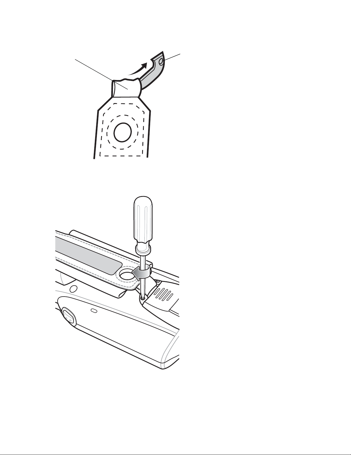
Figure 48: Remove Mounting Clip
Mounting
Clip
Strap Loop
4 Feed the mounting clip through the new strap loop.
5 Secure the mounting clip to the housing using the two screws.
Accessories | 53
Figure 49: Secure Mounting Clip
6 Feed the handstrap through the slot at the bottom of the device.
Page 54

54 | Accessories
Figure 50: Feed Handstrap Through Slot
7 Attach the hook material to the loop material and press together.
Figure 51: Secure Handstrap
Page 55

55 | USB Communication
Chapter
3
USB Communication
Note: This chapter applies to Android devices only.
This chapter provides information for transferring files between the device and a host computer.
Connecting to a Host Computer via USB
Connect the MC32N0 to a host computer using the Single Slot Serial/USB cradle or USB Client Charge cable to
transfer files between the MC32N0 and the host computer.
Caution:
When connecting the MC32N0 to a host computer, follow the host computer’s instructions for connecting
and disconnecting USB devices, to avoid damaging or corrupting files.
Connecting to the MC32N0 as a Media Device
Note: Using Media Device, you can copy files to either the microUSB card or internal memory.
Procedure:
1 Connect the USB Client Charge cable to the MC32N0 and then to the host computer or place the MC32N0 into a
Single Slot Serial/USB cradle that is connected to a host computer.
Connected as a media device or Connected as an installer appears on the Status bar.
2 If Connected as an installer appears, pull down the Notification shade and touch Connected as an installer and
then touch Media device (MTP).
3 On the host computer, open a file explorer application.
4 Locate the MC32N0 as a portable device.
5 Open the SD card or the Internal storage folder.
6 Copy or delete files as required.
Connecting to the MC32N0 as an Installer
Note: Using Installer, you can only copy files to the microUSB card.
Procedure:
1 Connect the USB Client Charge cable to the MC32N0 and then to the host computer or place the MC32N0 into a
Single Slot Serial/USB cradle that is connected to a host computer.
Connected as a media device or Connected as an installer appears on the Status bar.
Page 56

56 | USB Communication
2 If Connected as media device appears, pull down the Notification shade and touch Connected as media device
and then touch Media device (MTP) to de-select.
3 Touch Turn on USB Storage.
4 On the host computer, open a file explorer application.
The MC32N0 storage appears as Removable Disk.
5 Locate the MC32N0 as a devices within Removable Storage.
6 Open the Removable Disk.
7 Copy or delete files as required.
8 On the MC32N0, touch Turn off USB storage
Disconnect from the Host Computer
Caution:
Carefully follow the host computer’s instructions to unmount the microSD card and disconnect USB
devices correctly to avoid losing information.
Procedure:
1 On the host computer, unmount the device.
2 Remove the USB Client Charge cable from the MC32N0 or remove the MC32N0 from the Single Slot Serial/USB
cradle.
Page 57

Chapter
4
DataWedge Configuration
Note: This chapter applies to DataWedge on Android devices.
DataWedge is an application that reads data, processes the data and sends the data to an application.
Basic Scanning
Scanning can be performed using the imager.
57 | DataWedge Configuration
Using the Imager
To capture bar code data:
Procedure:
1 Ensure that an application is open on the
2 Aim the exit window at a bar code.
3 Press and hold the a Scan button or Trigger. The red laser aiming pattern turns on to assist in aiming. Ensure that
the bar code is within the area formed by the aiming pattern. The
Figure 52: Data Capture MC32N0-G
Figure 53: Data Capture – MC32N0–S
MC32N0 and a text field is in focus (text cursor in text field).
Page 58

DataWedge Configuration
58 |
4 The Scan LEDs light
captured data appears in the text field.
green, a beep sounds, by default, to indicate the bar code was decoded successfully. The
Using the Laser Scanner
To capture bar code data:
Procedure:
1 Ensure that an application is open on the device and a text field is in focus (text cursor in text field).
2 On the MC32N0–R, rotate the Turret for optimal scanning position.
3 Point the scan exit window at a bar code.
4 Press and hold the Scan button. The red scan line turns on to assist in aiming. Ensure that the scan line crosses
every bar and space of the bar code.
Figure 54: Data Capture MC32N0–R
Figure 55: Data Capture MC32N0–S
The Scan LEDs light green and a beep sounds, by default, to indicate the bar code was decoded successfully. The
captured data appears in the text field.
Profiles
DataWedge is based on profiles and plug-ins. A profile contains information on how DataWedge should behave with
different applications.
Profile information consists of:
Page 59

DataWedge Configuration | 59
• Associated application
Input plug-in configurations
•
• Output plug-in configurations
• Process plug-in configurations.
Using profiles, each application can have a specific DataWedge configuration. For example, each user application can
have a profile which outputs scanned data in the required format when that application comes to the foreground.
DataWedge can be configured to process the same set of captured data differently based on the requirements of each
application.
DataWedge includes the following visible and hidden pre-configured profiles which support specific built-in
applications:
• Visible profiles:
- Profile0 - created automatically the first time DataWedge runs. Generic profile used when there are no user
created profiles associated with an application.
- Launcher - disables scanning when the Launcher is in foreground.
- DWDemo - provides support for the DWDemo application.
• Hidden profiles (not shown to the device):
- RD Client - provides support for MSP.
- MSP Agent - provides support for MSP.
- MspUserAttribute - provides support for MSP.
- Camera - disables scanning when the default camera application is in foreground.
- RhoElements - disables scanning when RhoElements is in foreground.
Profile0
Profile0 can be edited but cannot be associated with an application. That is, DataWedge allows manipulation of
plug-in settings for Profile0 but it does not allow assignment of a foreground application. This configuration allows
DataWedge to send output data to any foreground application other than applications associated with user-defined
profiles when Profile0 is enabled.
Profile0 can be disabled to allow DataWedge to only send output data to those applications which are associated in
user-defined profiles. For example, create a profile associating a specific application, disable Profile0 and then scan.
DataWedge only sends data to the application specified in the user-created profile. This adds additional security to
DataWedge enabling the sending of data only to specified applications.
Plug-ins
A plug-in is a software module utilized in DataWedge to extend its functionality to encompass technologies such as
bar code scanning. The plug-ins can be categorized into three types based on their operations:
Input Plug-ins
•
• Output Plug-ins
• Process Plug-ins.
Input Plug-ins
An Input Plug-in supports an input device, such as a bar code scanner contained in, or attached to the device.
DataWedge contains base plug-ins for these input devices.
• Bar Code Scanner Input Plug-in – The Bar Code Scanner Input Plug-in is responsible for reading data from the
integrated bar code scanner and supports different types of bar code readers including laser, imager and internal
camera. Raw data read from the bar code scanner can be processed or formatted using Process Plug-ins as
Page 60

60 | DataWedge Configuration
required. DataWedge has built-in feedback functionality for the bar code scanner to issue user alerts. The
feedback settings can be configured according to user requirement.
Process Plug-ins
Process Plug-ins are used in DataWedge to manipulate the received data according to the requirement, before
sending to the foreground application via the Output Plug-in.
• Basic Data Formatting Process Plug-in – The Basic Data Formatting Plug-in allows DataWedge to add a prefix
and/or a suffix to the captured data before passing it to an Output Plug-in.
• Advanced Data Formatting Process Plug-in – The Advanced Data Formatting Plug-in allows DataWedge to
apply rules (actions to be performed based on defined criteria) to the data received via an input plug-in before
passing it to an Output Plug-in.
Output Plug-ins
Output Plug-ins are responsible for sending the data from Input Plug-ins to a foreground application on the device.
• Keystroke Output Plug-in – The Keystroke Output Plug-in collects and sends data received from the Input Plugin to the foreground applications by emulating keystrokes.
• Intent Output Plug-in – The Intent Output Plug-in collects and sends data received from the Input Plug-ins to
foreground applications using the Android Intent mechanism.
• IP Output Plug-in – The IP Output Plug-in collects and sends data received from the Input Plug-ins to a host
computer via a network connection. Captured data can be sent over an IP network to a specified IP address and
port using either TCP or UDP transport protocols.
Profiles Screen
To launch DataWedge, touch > DataWedge. By default, three profiles appear:
• Profile0
• Launcher
• DWDemo.
Profile0 is the default profile and is used when no other profile can be applied.
Figure 56: DataWedge Profiles Screen
Profile names are color coded. Enabled profiles are white and disabled profiles are gray.
To configure a profile touch the profile name.
Page 61

DataWedge Configuration | 61
Profile Context Menu
Touch and hold a profile to open a context menu that allows additional actions to be performed on the selected
profile.
Figure 57: Profile Context Menu
The profile context menu allows the profile to be edited (same as just tapping on a profile), renamed or deleted.
Options Menu
Press to open the options menu.
Figure 58: DataWedge Options Menu
The menu provides options to create a new profiles, access to general DataWedge settings and DataWedge version
information.
Disabling DataWedge
Procedure:
1
Touch .
2
Touch .
3
4 Touch Settings.
5 Touch DataWedge enabled.
Press
The blue check disappears from the checkbox indicating that DataWedge is disabled.
.
Page 62

62 | DataWedge Configuration
Creating a New Profile
Procedure:
1
Touch .
2
Touch .
3
4 Touch New profile.
5 In the New profile dialog box, enter a name for the new profile. It is recommended that profile names be unique
Press
and made up of only alpha-numeric characters (A-Z, a-z, 0-9).
Figure 59: New Profile Name Dialog Box
.
6 Touch OK.
The new profile name appears in the DataWedge profile screen.
Profile Configuration
To configure the Profile0 or a user-created profile, touch the profile name.
Figure 60: Profile Configuration Screen
The configuration screen lists the following sections:
Profile enabled
•
• Applications
• Barcode Input
• Keystroke output
• Intent Output
Page 63

DataWedge Configuration | 63
• IP Output.
Bar Code Input
Use the Bar Code Input options to configure the Bar Code Scanner Input Plug-in for the profile.
Enabled
Enables or disables this plug-in. A check in the checkbox indicates that the plug-in is enabled.
Scanner Selection
Configures which scanning device to use for bar code data capture when the profile is active.
• Auto - The software automatically selects the 2D Imager.
• 2D Imager - Scanning is performed using the 2D Imager.
Decoders
Configures which bar code decoders are enabled or disabled. For best performance disable all unnecessary decoders.
Touch Decoders. The Barcode input screen appears. A check in the checkbox indicates that the decoder is enabled.
By default the most commonly used decoders are enabled (shown below with an asterisk). The supported decoders
are:
UPC-A* UPC-E0* EAN-13*
EAN-8* Code 128* Code 39*
Interleaved 2 of 5 GS1 DataBar* GS1 DataBar Limited
GS1 DataBar Expanded Datamatrix* QR Code*
PDF417* Composite AB Composite C
MicroQR Aztec* Maxicode*
MicroPDF USPostnet USPlanet
UK Postal Japanese Postal Australian Postal
Canadian Postal Dutch Postal US4state FICS
Codabar* MSI Code 93
Trioptic 39 Discrete 2 of 5 Chinese 2 of 5
Korean 3 of 5 Code 11 TLC 39
Matrix 2 of 5 UPC-E1
Press to return to the previous screen.
Decoder Params
Use Decode Params to configure individual decoder parameters.
• UPCA
- Report Check Digit - The check digit is the last character of the symbol used to verify the integrity of the
data. Enables or disables this option. A check in the checkbox indicates that the option is enabled (default enabled).
- Preamble - Preamble characters are part of the UPC symbol consisting of Country Code and System
Character. Select the appropriate option to match the host system.
Page 64

64 | DataWedge Configuration
There are three options for transmitting a UPCA preamble:
+ Preamble None - Transmit no preamble.
+ Preamble Sys Char - Transmit System Character only (default).
+ Preamble Country and Sys Char - Transmit System Character and Country Code (“0” for USA). Select
the appropriate option to match the host system.
• UPCE0
- Report Check Digit - The check digit is the last character of the symbol used to verify the integrity of the
data. Enables or disables this option. A check in the checkbox indicates that the option is enabled (default disabled).
- Preamble - Preamble characters are part of the UPC symbol consisting of Country Code and System
Character. Select the appropriate option to match the host system.
There are three options for transmitting a UPCE0 preamble:
+ Preamble Sys Char - Transmit System Character only.
+ Preamble Country and Sys Char - Transmit System Character and Country Code (“0” for USA).
+ Preamble None - Transmit no preamble (default).
- Convert UPCE0 To UPCA - Enable to convert UPCE0 (zero suppressed) decoded data to UPC-A format
before transmission. After conversion, the data follows UPC-A format and is affected by UPC-A programming
selections. Disable to transmit UPCE0 decoded data as UPCE0 data, without conversion (default - disabled).
• Code128
- Length1 - Use to set decode lengths (default - 0). See Decode Lengths on page 67 for more information.
- Length2 - Use to set decode lengths (default - 55). See Decode Lengths on page 67 for more information.
- Redundancy - Sets the reader to read the bar code twice before accepting data. A check in the checkbox
indicates that redundancy is enabled (default - disabled).
- Enable Plain Code 128 - Flag to enable other 128 sub types (besides GS1-128 and ISBT-128).
- Enable GS1-128 - Set the GS1 128 subtype. A check in the checkbox indicates that the option is enabled
(default - enabled).
- Enable ISBT128 - Set the ISBT128 subtype. A check in the checkbox indicates that the option is enabled
(default - enabled).
- ISBT128 Concatenation Mode - Select an option for concatenating pairs of ISBT code types:
+ Concat Mode Never - Do not concatenate pairs of ISBT codes encountered (default).
+ Concat Mode Always - There must be two ISBT codes in order to decode and perform concatenation.
Does not decode single ISBT symbols.
+ Concat Mode Auto - Decodes and concatenates pairs of ISBT codes immediately. If only a single ISBT
symbol is present, the device must decode the symbol the number of times set via DataWedge
Configuration 4 - 11 Redundancy - Code128 before transmitting its data to confirm that there is no
additional ISBT symbol.
- Check ISBT Table - The ISBT specification includes a table that lists several types of ISBT bar codes that are
commonly used in pairs. If ISBT128 Concat Mode is set, enable Check ISBT Table to concatenate only those
pairs found in this table. Other types of ISBT codes are not concatenated. A check in the checkbox indicates
that redundancy is enabled (default - disabled).
- Security Level - The scanner offers four levels of decode security for Code 128 bar codes. Select increasing
levels of security for decreasing levels of bar code quality. There is an inverse relationship between security
and scanner aggressiveness, so choose only that level of security necessary for any given application.
+ Security Level 0 - This setting allows the scanner to operate in its most aggressive state, while providing
sufficient security in decoding most “in-spec” bar codes.
+ Security Level 1 - This setting eliminates most misdecodes (default).
+ Security Level 2 - Select this option if Security level 1 fails to eliminate misdecodes.
+ Security Level 3 - If Security Level 2 is selected and misdecodes still occur, select this security level. Be
advised, selecting this option is an extreme measure against mis-decoding severely out of spec bar codes.
Page 65

DataWedge Configuration | 65
Selecting this level of security significantly impairs the decoding ability of the scanner. If this level of
security is needed, try to improve the quality of the bar codes.
• Code39
- Length1 - Use to set decode lengths (default - 0). See Decode Lengths on page 67 for more information.
- Length2 - Use to set decode lengths 4 (default - 55). See Decode Lengths on page 67 for more information.
- Verify Check Digit - Enable this feature to check the integrity of all Code 39 symbols to verify that the data
complies with a specified check digit algorithm. The digital scanner decodes only those Code 39 symbols that
include a modulo 43 check digit. Enable this feature only if the Code 39 symbols contain a modulo 43 check
digit (default - disabled).
- Report Check Digit - Transmit Code 39 data with or without the check digit. A check in the checkbox
indicates to send Code 39 data with check digit (default - disabled).
- Full ASCII - Code 39 Full ASCII is a variant of Code 39 that pairs characters to encode the full ASCII
character set. To enable or disable Code 39 Full ASCII (default - disabled),
- Redundancy - Sets the reader to read the bar code twice before accepting data. A check in the checkbox
indicates that redundancy is enabled (default - disabled).
- Convert Code39 To Code32 - Code 32 is a variant of Code 39 used by the Italian pharmaceutical industry.
Scan the appropriate bar code below to enable or disable converting Code 39 to Code 32 (default - disabled).
- Report Code32 Prefix - Scan the appropriate bar code to enable or disable adding the prefix character “A” to
all Code 32 bar codes (default - disabled).
- Security Level - Options: Security level 0, Security Level 1, Security Level 2 and Security Level 3 (default
- Security level 1).
• Interleaved 2 of 5
- Length1 - Use to set decode lengths (default - 14). See Decode Lengths on page 67 for more information.
- Length2 - Use to set decode lengths (default - 10). See Decode Lengths on page 67 for more information.
- Redundancy - Sets the reader to read the bar code twice before accepting data. A check in the checkbox
indicates that redundancy is enabled (default - enabled).
- Check Digit
+ No Check Digit - A check digit is not used. (default)
+ USS Check Digit - Select to check the integrity of all Interleaved 2 of 5 symbols to verify the data
complies with either the Uniform Symbology Specification (USS) check digit algorithm.
+ OPCC Check Digit - Select to check the integrity of all Interleaved 2 of 5 symbols to verify the data
complies with either the Optical Product Code Council (OPCC) check digit algorithm.
- Report Check Digit - Transmit Interleaved 2 of 5 data with or without the check digit. A check in the
checkbox indicates to send Interleaved 2 of 5 data with check digit (default - disabled).
- Convert ITF-14 To EAN13 - Convert 14-character Interleaved 2 of 5 bar codes to EAN-13, and transmit as
EAN-13. The Interleaved 2 of 5 bar code must be enabled and must have a leading zero and a valid EAN-13
check digit. A check in the checkbox indicates that the option is enabled (default - disabled).
- I2of5 Security Level - Options: I2of5 Security level 0, I2of5 Security Level 1, I2of5 Security Level 2 and
I2of5 Security Level 3 (default - I2of5 Security level 1).
• Composite AB
- UCC Link Mode
+ Link Flag ignored - 1D component is transmitted regardless of whether a 2D component is detected.
+ Always Linked - 1D and the 2D components are transmitted. If 2D is not present, the 1D component is not
transmitted.
+ Auto Discriminate - the digital scanner determines if there is a 2D portion, then transmits the 1D
component, as well as the 2D portion if present. (default).
• UK Postal
- Report Check Digit - Transmit UK Postal data with or without the check digit. A check in the checkbox
indicates to send UK Postal data with check digit (default - disabled).
• Codabar
Page 66

66 | DataWedge Configuration
- Length1 - Use to set decode lengths (default - 6). See Decode Lengths on page 67 for more information.
- Length2 - Use to set decode lengths (default - 55). See Decode Lengths on page 67 for more information.
- Redundancy - Sets the reader to read the bar code twice before accepting data. A check in the checkbox
indicates that redundancy is enabled (default - enabled).
- CLSI Editing - Enable this parameter to strip the start and stop characters and insert a space after the first,
fifth, and tenth characters of a 14-character Codabar symbol. Enable this feature if the host system requires this
data format (default - disabled).
- NOTIS Editing - Enable this parameter to strip the start and stop characters from a decoded Codabar symbol.
Enable this feature if the host system requires this data format (default - disabled).
• MSI
- Length 1 - Use to set decode lengths (default - 4). See Decode Lengths on page 67 for more information.
- Length 2 - Use to set decode lengths (default - 55). See Decode Lengths on page 67 for more information.
- Redundancy - Sets the reader to read the bar code twice before accepting data. A check in the checkbox
indicates that redundancy is enabled (default - enabled).
- Check Digit - With MSI symbols, one check digit is mandatory and always verified by the reader. The second
check digit is optional.
+ One Check Digit - Verify one check digit (default).
+ Two Check Digits - Verify two check digits.
- Check Digit Scheme - Two algorithms are possible for the verification of the second MSI check digit. Select
the algorithm used to encode the check digit.
+ Mod-11-10 - First check digit is MOD 11 and second check digit is MOD 10 (default).
+ Mod-10-10 - Both check digits are MOD 10.
- Report Check Digit - Transmit MSI data with or without the check digit. A check in the checkbox indicates to
send MSI data with check digit (default - disabled).
• Code93
- Length1 - Use to set decode lengths (default - 0). See Decode Lengths on page 67 for more information.
- Length2 - Use to set decode lengths (default - 55). See Decode Lengths on page 67 for more information.
- Redundancy - Sets the reader to read the bar code twice before accepting data. A check in the checkbox
indicates that redundancy is enabled (default - disabled).
• Discrete 2 of 5
- Length1 - Use to set decode lengths (default - 0). See Decode Lengths on page 67 for more information.
- Length2 - Use to set decode lengths (default - 14). See Decode Lengths on page 67 for more information.
- Redundancy - Sets the reader to read the bar code twice before accepting data. A check in the checkbox
indicates that redundancy is enabled (default - enabled).
• Code 11
- Length1 - Use to set decode lengths (default - 4). See Decode Lengths on page 67 for more information.
- Length2 - Use to set decode lengths (default - 55). See Decode Lengths on page 67 for more information.
- Redundancy - Sets the reader to read the bar code twice before accepting data. A check in the checkbox
indicates that redundancy is enabled (default - enabled).
- Verify Check Digit - Check the integrity of all Code 11 symbols to verify that the data complies with the
specified check digit algorithm. This selects the check digit mechanism for the decoded Code 11 bar code.
+ No Check Digit - Do not verify check digit.
+ 1 Check Digit - Bar code contains one check digit (default).
+ 2 Check Digits - Bar code contains two check digits.
- Report Check Digit - Transmit Code 11 data with or without the check digit. A check in the checkbox
indicates to send Code 11 data with check digit (default - disabled).
• Matrix 2 of 5
- Length1 - Use to set decode lengths (default - 10). See Decode Lengths on page 67 for more information.
- Length2 - Use to set decode lengths (default - 0). See Decode Lengths on page 67 for more information.
Page 67

DataWedge Configuration | 67
- Redundancy - Sets the reader to read the bar code twice before accepting data. A check in the checkbox
indicates that redundancy is enabled (default - disabled).
- Report Check Digit - Transmit Matrix 2 of 5 data with or without the check digit. A check in the checkbox
indicates to send Matrix 2 of 5 data with check digit (default - enabled).
- Verify Check Digit - Enable this feature to check the integrity of all Matrix 2 of 5 symbols to verify that the
data complies with a specified check digit algorithm (default - enabled).
• UPCE1
- Report Check Digit - The check digit is the last character of the symbol used to verify the integrity of the
data. Enables or disables this option. A check in the checkbox indicates that the option is enabled (default disabled).
- Preamble - Preamble characters are part of the UPC symbol consisting of Country Code and System
Character. Select the appropriate option to match the host system.
There are three options for transmitting a UPCE1 preamble:
+ Preamble Sys Char - Transmit System Character only.
+ Preamble Country and Sys Char - Transmit System Character and Country Code (“0” for USA).
+ Preamble None - Transmit no preamble (default).
- Convert UPCE1 To UPCA - Enable this to convert UPCE1 decoded data to UPC-A format before
transmission. After conversion, the data follows UPC-A format and is affected by UPC-A programming
selections. Disable this to transmit UPCE1 decoded data as UPCE1 data, without conversion (default disabled).
Decode Lengths
The allowable decode lengths are specified by options Length1 and Length2 as follows:
Variable length: Decode symbols containing any number of characters.
•
- Set both Length1 and Length2 to 0.
• Range: Decode a symbol with a specific length range (from a to b, including a and b).
- Set Length1 to a and set Length2 to b.
• Two Discrete Lengths: Decode only symbols containing either of two selected lengths.
- Set both Length1 or Length2 to the specific lengths. Length1 must be greater than Length2.
• One Discrete Length: Decode only symbols containing a specific length.
- Set both Length1 and Length2 to the specific length.
UPC EAN Params
Allows the configuration of the parameters that apply to more than one UPC or EAN decoder.
• Security Level - The scanner offers four levels of decode security for UPC/EAN bar codes. Select higher security
levels for lower quality bar codes. There is an inverse relationship between security and decode speed, so be sure
to choose only that level of security necessary for the application.
- Level 0 - This default setting allows the scanner to operate fastest, while providing sufficient security in
decoding “in-spec” UPC/EAN bar codes (default).
- Level 1 - As bar code quality levels diminish, certain characters become prone to misdecodes before others
(i.e., 1, 2, 7, 8). If the scanner is misdecoding poorly printed bar codes, and the misdecodes are limited to these
characters, select this security level.
- Level 2 - If the scanner is misdecoding poorly printed bar codes, and the misdecodes are not limited to
characters 1, 2, 7, and 8, select this security level.
- Level 3 - If the scanner is still misdecoding, select this security level. Be advised, selecting this option is an
extreme measure against misdecoding severely out of spec bar codes. Selecting this level of security can
significantly impair the decoding ability of the scanner. If this level of security is necessary, try to improve the
quality of the bar codes.
Page 68

68 | DataWedge Configuration
• Supplemental2 - Enables or disables this option. A check in the checkbox indicates that the option is enabled.
• Supplemental5 - Enables or disables this option. A check in the checkbox indicates that the option is enabled.
• Supplemental Mode
- No Supplementals - the scanner is presented with a UPC/EAN plus supplemental symbol, the scanner
decodes UPC/EAN and ignores the supplemental characters (default).
- Supplemental Always - the scanner only decodes UPC/EAN symbols with supplemental characters, and
ignores symbols without supplementals.
- Supplements Auto - the scanner decodes UPC/EAN symbols with supplemental characters immediately. If
the symbol does not have a supplemental, the scanner must decode the bar code the number of times set via
UPC/EAN Supplemental Redundancy before transmitting its data to confirm that there is no supplemental.
- Supplemental Smart - Enables smart supplementals. In this mode the decoder returns the decoded value of
the main block right away if it does not belong to one of the following supplemental types: 378, 379, 977, 978,
979, 414, 419, 434 or 439. If the bar code starts with one of the prefixes it searches the image more
aggressively for a supplemental. Tries to scan the supplemental if it is present. If the supplemental scanning
failed, then the main bar code is returned.
- Supplemental 378-379 - Enables (auto-discriminate) supplemental for UPC/EAN codes starting with 378 or
379. Disables reading of supplementals for any other UPC/EAN bar code not starting with 378 or 379. Tries to
scan the supplemental if it is present. If the supplemental scanning failed, then the main bar code is returned.
- Supplemental 978-979 - Enables (auto-discriminate) supplemental for UPC/EAN codes starting with 978 or
979. Disables reading of supplementals for another UPC/EAN bar code not starting with 978 or 979. Tries to
scan the supplemental if it is present. If the supplemental scanning failed, then the main bar code is returned.
- Supplemental 414-419-434-439 - Enables (auto-discriminate) supplemental for UPC/EAN codes starting with
414, 419, 434 or 439. Disables reading of supplementals for another UPC/EAN bar code 4 - 16 not starting
with 414, 419, 434 or 439. Tries to scan the supplemental if it is present. If the supplemental scanning failed,
then the main bar code is returned.
- Supplemental 977 - Enables (auto-discriminate) supplemental for UPC/EAN codes starting with 977.
Disables reading of supplementals for another UPC/EAN barcode not starting with 977. Tries to scan the
supplemental if it is present. If the supplemental scanning failed, then the main bar code is returned.
• Retry Count - Retry count for auto-discriminating for supplementals. Possible values are 2 to 20 inclusive. Note
that this flag is only considered if Supplemental Mode - UPC EAN is set to one of the following values:
Supplementals Auto, Supplementals Smart, Supplementals 378-379, Supplementals 978-979, Supplementals
977 or Supplementals 414-419-434-439 (2 to 20, default 10).
• Bookland - Enable Bookland decoding. A check in the checkbox indicates that the option is enabled.
• Coupon - Enables Coupon code decoding. Note that in order to successfully decode Coupon codes, all of the
correct decoders must be enabled. A check in the checkbox indicates that the option is enabled.
• Convert DataBar To UPC EAN - If this is set it converts DataBar bar codes to UPC/EAN format. For this
setting to work UPC/EAN symbologies must be enabled. A check in the checkbox indicates that the option is
enabled.
Reader Params
Allows the configuration of parameters specific to the selected bar code reader.
• Beam Timer - Sets the maximum amount of time that the reader remains on (0 - 60,000 ms in increments of 100
ms). A value of 0 sets the reader to stay on indefinitely (default -15000).
• Linear Security Level - Sets the number of times a bar code is read to confirm an accurate decode.
- Security Short or Codabar - Two times read redundancy if short bar code or Codabar.
- Security All Twice - Two times read redundancy for all bar codes (default).
- Security Long and Short - Two times read redundancy for long bar codes, three times for short bar codes.
- Security All Thrice - Three times read redundancy for all bar codes.
• Picklist - Allows the imager to decode only the bar code that is directly under the cross-hair/reticle (+) part of the
pattern. This feature is useful in applications where multiple bar codes may appear in the field of view during a
decode session and only one of them is targeted for decode.
Page 69

DataWedge Configuration | 69
- Disable – Disables Picklist mode. Any bar code within the field of view can be decoded (default).
- Centered - Enables the Picklist mode so that only the bar code in the center of the image is decoded. This is
most useful when used in conjunction with the static and dynamic reticle viewfinder modes. Note: This mode
is only valid for decoder modules that supports a viewfinder. If one tries to set this for a unsupported decoder
then the device would issue an error. (Camera scanner only).
- Reticle - Enables the Picklist mode so that only the bar code that is directly under the cross-hair (reticle) is
decoded. This is useful when used in conjunction with the static and dynamic reticle viewfinder modes. (Scan
Module Only)
• LCD Mode - Enables or disables LCD mode. LCD mode enhances the ability of the imager to read bar codes
from LCD displays such as cellphones (imager only).
- Disable - Disables the LCD mode (default).
- Enable - Enables LCD mode.
Note: When using the LCD mode, a degradation in performance may be observed and the aiming
crosshair may blink until the bar code is decoded.
• Illumination mode - Turns camera illumination on and off. This option is only available when camera is selected
in the Barcode input Scanner selection option.
- On - Illumination is on.
- Off - Illumination is off (default).
• Inverse 1D Mode - This parameter allows the user to select decoding on inverse 1D bar codes.
- Disable - Disables decoding of inverse 1D bar codes (default).
- Enable - Enables decoding of only inverse 1D bar codes.
- Auto - Allows decoding of both twice positive and inverse 1D bar codes.
• Viewfinder Mode - Configures the Viewfinder modes supported for camera scanning.
- Viewfinder Enabled - Enables only the viewfinder.
- Static Reticle - Enables the viewfinder and a red reticle in the center of the screen which helps selecting the
bar code (default).
Scan Params
Allows the configuration of Code ID and decode feedback options.
• Code ID Type - A Code ID character identifies the code type of a scanned bar code. This is useful when the
reader is decoding more than one code type. Select a code ID character to insert between the prefix and the
decoded symbol.
- Code ID Type None - No prefix (default).
- Code ID Type Aim - A standards based three character prefix.
- Code ID Type Symbol - A Symbol defined single character prefix.
Note: Not all ringtones are fully supported as decode tones and those of longer length may be truncated
when used as a decode tone. The recommendation is to test the selected tone for operation before
deployment to a customer site.
• Decode Audio Feedback - Select an audio tone to sound upon a good decode.
• Decode Haptic Feedback - Enable the device to vibrate upon a good decode (default - enabled).
MSR Input
Use MSR Input options to configure the MSR Input Plug-in for the profile.
• Enabled — Enables or disables this plug-in. A check in the checkbox indicates that the plug-in is enabled.
Page 70

70 | DataWedge Configuration
Keystroke Output
Use to configure the Keystroke Output Plug-in for the profile.
• Enabled — Enables or disables this plug-in. A check in the checkbox indicates that the plug-in is enabled (default
- enabled).
• Action key character - Enables decoding of a special character embedded within a bar code data for use in native
Android applications. This feature is helpful when populating or executing a form.
- None - Action key character feature is disabled (default).
- Tab - Tab character code in a bar code is processed. When DataWedge detects this character code in a bar
code, move the focus to the next field.
- Line feed - Line feed character code in a bar code is processed. When DataWedge detects this character code
in a bar code, move the focus to the next field.
- Carriage return - Carriage return character code in a bar code is processed. When DataWedge detects this
character code in a bar code, move the focus to the next field.
• Advanced data formatting - is a way to customizing data before transmission. Use advanced data formatting
(ADF) to edit scan data to suit requirements.
- Enable - Enables or disables ADF. A check in the checkbox indicates that ADF is enabled (default - disabled).
- Rules - ADF uses rules to customize data. These rules perform detailed actions when the data meets certain
criteria. One rule may consist of single or multiple criteria applied to single or multiple actions. See
Generating Advanced Data Formatting Rules
on page 75 for more information.
• Basic data formatting - Allows the configuration of any data formatting for the related Output Plug-in. When the
plug-in is disabled, any data is passed on without modification.
- Enabled - Enables or disables Basic Data Formatting. A check in the checkbox indicates that it is enabled
(default - enabled).
- Prefix to data - Add characters to the beginning of the data when sent.
- Suffix to data - Add characters to the end of the data when sent.
- Send data - Set to transfer the captured data to the foreground application. Disabling this option prevents the
actual data from being transmitted. However, the prefix and suffix strings, if present, are still transmitted even
when this option is disabled (default - enabled).
- Send as hex - Set to send the data in hexadecimal format. A check in the checkbox indicates that the plug-in is
enabled (default - disabled).
- Send TAB key - Set to append a tab character to the end of the processed data. A check in the checkbox
indicates that the plug-in is enabled (default - disabled).
- Send ENTER key - Set to append an Enter character to the end of the processed data. A check in the
checkbox indicates that the plug-in is enabled (default - disabled).
Intent Output
Allows configuration of the Intent Output Plug-in for the profile. The Intent Output Plug-in allows the captured data
to be sent to an application in the form of an implicit Intent. Refer to the Android Developer web site for more
information, http://developer.android.com.
• Enabled - Enables or disables this plug-in. A check in the checkbox indicates that the plug-in is enabled (default disabled).
• Intent action - Enter the Intent Action name (required).
• Intent category - Enter the Intent Category name (required).
• Intent delivery - Select the method by which the intent is delivered:
- Send via StartActivity
- Send via startService (default)
- Broadcast intent
Page 71

DataWedge Configuration | 71
• Advanced data formatting - is a way to customizing data before transmission. Use advanced data formatting
(ADF) to edit scan data to suit requirements.
- Enable - Enables or disables ADF. A check in the checkbox indicates that ADF is enabled (default - disabled).
- Rules - ADF uses rules to customize data. These rules perform detailed actions when the data meets certain
criteria. One rule may consist of single or multiple criteria applied to single or multiple actions. See
Generating Advanced Data Formatting Rules
• Basic data formatting - Allows configuration of any data formatting for the related Output Plug-in. When the
plug-in is disabled any data is passed on without modification.
- Enabled - Enables or disables Basic Data Formatting. A check in the checkbox indicates that it is enabled
(default - enabled).
- Prefix to data - Add characters to the beginning of the data when sent.
- Suffix to data - Add characters to the end of the data when sent.
- Send data - Set to transfer the captured data to the foreground application. Disabling this option prevents the
actual data from being transmitted. However, the prefix and suffix strings, if present, are still transmitted even
when this option is disabled (default - enabled).
- Send as hex - Set to send the data in hexadecimal format. A check in the checkbox indicates that the plug-in is
enabled (default - disabled).
- Send TAB key - Set to append a tab character to the end of the processed data. A check in the checkbox
indicates that the plug-in is enabled (default - disabled).
- Send ENTER key - Set to append an Enter character to the end of the processed data. A check in the
checkbox indicates that the plug-in is enabled (default - disabled).
on page 75 for more information.
Intent Overview
The core components of an Android application (its activities, services, and broadcast receivers) are activated by
intents. An intent is a bundle of information (an Intent object) describing a desired action - including the data to be
acted upon, the category of component that should perform the action, and other pertinent instructions. Android
locates an appropriate component to respond to the intent, launches a new instance of the component if one is needed,
and passes it the Intent object.
Components advertise their capabilities, the kinds of intents they can respond to, through intent filters. Since the
system must learn which intents a component can handle before it launches the component, intent filters are specified
in the manifest as <intent-filter>elements. A component may have any number of filters, each one describing a
different capability. For example, if the manifest contains the following:
<intent-filter . . . >
<action android:name=”android.intent.action.DEFAULT” />
<category android:name=”android.intent.category.MAIN” />
</intent-filter>
In the Intent output plug-in configuration, the Intent action would be:
android.intent.category.DEFAULT
and the Intent category would be:
android.intent.category.MAIN.
The Intent delivery option allows the method by which the intent is delivered to be specified. The delivery
mechanisms are Send via startActivity, Send via startService or Broadcast intent.
The decode related data added to the Intent’s bundle can be retrieved using the Intent.getStringExtra() and
Intent.getSerializableExtra() calls, using the following String tags:
• String LABEL_TYPE_TAG = “com.symbol.emdk.datawedge.label_type”;
Page 72

72 | DataWedge Configuration
- String contains the label type of the bar code.
String DATA_STRING_TAG = “com.symbol.emdk.datawedge.data_string”;
•
- String contains the output data as a String. In the case of concatenated bar codes, the decode data is
concatenated and sent out as a single string.
• String DECODE_DATA_TAG = “com.symbol.emdk.datawedge.decode_data”;
- Decode data is returned as a list of byte arrays. In most cases there will be one byte array per decode. For bar
code symbologies that support concatenation e.g. Codabar, Code128, MicroPDF, etc., the decoded data is
stored in multiple byte arrays (one byte array per bar code). Clients can get data in each byte array by passing
an index.
Most scanning applications might want the user to be able to decode data and for that decode data to be sent to the
*current* activity but not necessarily displayed. If this is the case, then the activity needs to be marked as
‘singleTop’ in its AndroidManifest.xml file. If your activity is not defined as singleTop, then on every decode, the
system will create another copy of your Activity and send the decode data to this second copy.
Finally there will be a configuration option for each process plug-in so that the process plug-in can be configured
specifically for the intent output, which in this case is the basic data formatting process plug-in.
IP Output
Note: IPWedge application is required on a host computer. Download the IPWedge application from the
Support Central web site: http://www.zebra.com/support.
IP Output allows DataWedge to send captured data to a host computer via a network connection. Captured data can
be sent over an IP network to a specified IP address and port using either TCP or UDP transport protocols.
• Enabled - Enables or disables this plug-in. A check in the checkbox indicates that the plug-in is enabled (default disabled).
• Remote Wedge - Enable or disable the Remote Wedge option (default - enabled). Remote Wedge is used with the
IPWedge application.
• Protocol - Select the protocol used by the remote application. Options: TCP (default) or UDP.
• IP address - Enter the IP address used by the remote application (default - 0.0.0.0).
• Port - Enter the port number used by the remote application (default - 58627).
• Advanced data formatting - is a way of customizing data before transmission. Use advanced data formatting
(ADF) to edit scan data to suit requirements.
- Enable - Enables or disables ADF. A check in the checkbox indicates that ADF is enabled (default - disabled).
- Rules - ADF uses rules to customize data. These rules perform detailed actions when the data meets certain
criteria. One rule may consist of single or multiple criteria applied to single or multiple actions. See
Generating Advanced Data Formatting Rules
• Basic data formatting - Allows configuration of any data formatting for the related Output Plug-in. When the
plug-in is disabled any data is passed on without modification.
- Enabled - Enables or disables Basic Data Formatting. A check in the checkbox indicates that it is enabled
(default - enabled).
- Prefix to data - Add characters to the beginning of the data when sent.
- Suffix to data - Add characters to the end of the data when sent.
- Send data - Set to transfer the captured data to the foreground application. Disabling this option prevents the
actual data from being transmitted. However, the prefix and suffix strings, if present, are still transmitted even
when this option is disabled (default - enabled).
- Send as hex - Set to send the data in hexadecimal format. A check in the checkbox indicates that the plug-in is
enabled (default - disabled).
- Send TAB key - Set to append a tab character to the end of the processed data. A check in the checkbox
indicates that the plug-in is enabled (default - disabled).
- Send ENTER key - Set to append an Enter character to the end of the processed data. A check in the
checkbox indicates that the plug-in is enabled (default - disabled).
on page 75 for more information.
Page 73

DataWedge Configuration | 73
Usage
This section provides information on how to configure IP Output using the DataWedge configuration user interface.
To use IP Output in a particular DataWedge profile (for example: Profile0), scroll downward on IP Output.
Figure 61: IP Output Screen
Using IP Output with IPWedge
IPWedge is a computer application that can be easily configured to retrieve data sent over network by DataWedge IP
Output. Refer to the IPWedge User Manual on how to install and configure in a host computer. To enable IP Output
to send captured data to a remote computer that is installed with IPWedge:
Procedure:
1 In IP Output, touch Enabled.
A check appears in the checkbox.
2 Ensure Remote Wedge option is enabled.
3 Touch Protocol.
4 In the Choose protocol dialog box, touch the same protocol selected for the IPWedge computer application.
(TCP is the default).
Figure 62: Protocol Selection
5 Touch IP Address.
6 In the Enter IP Address dialog box, enter the IP address of host computer to send data to.
Page 74

74 | DataWedge Configuration
Figure 63: IP Address Entry
7 Touch Port.
8 In the Enter port number dialog box, enter same port number selected for IPWedge computer application.
Figure 64: Port Number Entry
9 Configure Advanced data formatting and Basic data formatting Plug-in if any required modification to be done
to captured data before sending to remote computer.
Using IP Output without IPWedge
IP Output Plug-in can be used to send captured data from DataWedge to a remote device or host computer without
using IPWedge. At the data receiving end, the host computer or mobile device should have an application, that listens
to TCP or UDP data coming from a configured port and IP address in the IP Output plug-in. To enable IP Output to
send captured data to a remote computer:
Procedure:
1 In IP Output, touch Enabled.
A check appears in the checkbox.
2 Ensure Remote Wedge option is disabled.
3 Touch Protocol.
4 In the Choose protocol dialog box, touch the same protocol selected in the client application. (TCP is the default).
Figure 65: Protocol Selection
5 Touch IP Address.
6 In the Enter IP address dialog box, enter the IP address of host computer to send data to.
Page 75

DataWedge Configuration | 75
Figure 66: IP Address Entry
7 Touch Port.
8 In the Enter port number dialog box, enter the port number that the host computer application is listening on.
Figure 67: Port Number Entry
9 Configure Advanced Data Formatting and Basic Data Formatting Plug-in if any required modification to be
done to captured data before sending to remote computer.
Generating Advanced Data Formatting Rules
The ADF plug-in applies rules (actions to be performed based on defined criteria) to the data received via an input
plug-in before sending it to the output plug-in.
•
Rules - The ADF process plug-in consists of one or more rules. DataWedge formats the output data according to
the first matching rule. A rule is a combination of criteria and a set of actions to be performed, upon fulfillment of
the criteria set in the rule.
• Criteria - Criteria can be set according to Input plug-in, symbology, matching string within the data (at the
specified position) and/or data length. Received data must match the defined criteria in order for the data to be
processed.
• Actions - A set of procedures defined to format data. There are four types of actions which are for formatting
cursor movement, data modification, data sending and delay specifications. An action can be defined to send the
first number of characters to the Output plug-in, pad the output data with spaces or zeros, remove spaces in data,
etc.
Configuring ADF Plug-in
Configuring the ADF plug-in consists of creating a rule, defining the criteria and defining the actions.
Procedure:
1
Touch
2
Touch .
3 Touch a DataWedge profile.
4 In Keystroke Output, touch Advanced data formatting.
.
Page 76

76 | DataWedge Configuration
Figure 68: Advanced Data Formatting Screen
5 Touch the Enable checkbox to enable ADF.
Creating a Rule
Note: By default, Rule0, is the only rule in the Rules list.
Procedure:
1
Press
2 Touch New rule.
3 Touch the Enter rule name text box.
4 In the text box, enter a name for the new rule.
5 Touch Done.
6 Touch OK.
.
Defining a Rule
Procedure:
1 Touch the newly created rule in the Rules list.
Figure 69: Rule List Screen
2 Touch the Rule enabled checkbox to enable the current rule.
Page 77

Defining Criteria
Procedure:
1 Touch Criteria.
Figure 70: Criteria Screen
DataWedge Configuration | 77
2 Touch String to check for option to specify the string that must be present in the data.
3 In the Enter the string to check for dialog box, enter the string
4 Touch Done.
5 Touch OK.
6 Touch String position option to specify the position of the string specified in the String to check for option. The
ADF rule is only applied if the specific string in String to check for is found at the specified String position
location (zero for the start of the string).
7 Touch the + or - to change the value.
8 Touch OK.
9 Touch String length option to specify a length for the received data. The ADF rule only applies to the bar code
data with that specified length.
10 Touch the + or - to change the value.
11 Touch OK.
12 Touch Source criteria option to associate an input device to an ADF rule. The ADF rule only applies to data
received from associated input devices.
13 Touch Barcode input.
14 Touch the Source enabled checkbox to accept data from this source.
Figure 71: Barcode Input Screen
Page 78

78 | DataWedge Configuration
15 For Barcode inputs, touch the All decoders enabled checkbox to select all bar code symbologies. Deselect the
All decoders enabled checkbox to individually select the symbologies.
16
17 If required, repeat steps to create another rule.
18
Press
Press
until the Rule screen appears.
until the Rule screen appears.
Defining an Action
Note: By default the Send remaining action is in the Actions list.
Procedure:
1
Press .
2 Touch New action.
3 In the New action menu, select an action to add to the Actions list. See Table 8: ADF Supported Actions
78 for a list of supported ADF actions.
4 Some Actions require additional information. Touch the Action to display additional information fields.
5 Repeat steps to create more actions.
6
Press
7
Press
.
.
on page
Deleting a Rule
Procedure:
1 Touch and hold on a rule until the context menu appears.
2 Touch Delete to delete the rule from the Rules list.
Note: When there is no rule available for ADF plug-in or all rules are disabled, DataWedge passes
decoded data to the output plug-in without processing the data.
Order Rules List
Note: When there are no rules defined, ADF passes the captured data through as is. In contrast, when rules
are defined but all are disabled, ADF does not pass any captured data through.
Rules are processed in top-down order. The rules that are on top of the list are processed first. Use the icon next to the
rule to move it to another position in the list.
Table 8: ADF Supported Actions
Type Actions Description
Cursor Movement
Skip ahead Moves the cursor forward by a specified number of characters. Enter the
number of characters to move the cursor ahead.
Skip back Moves the cursor back by a specified number of characters. Enter the
number of characters to move the cursor back.
Skip to start Moves the cursor to the beginning of the data.
Move to Moves the cursor forward until the specified string is found. Enter the
string in the data field.
Table continued…
Page 79

Type Actions Description
Move past a Moves the cursor forward past the specified string. Enter the string in
the data field.
DataWedge Configuration | 79
Data Modification
Crunch spaces Remove spaces between words to one and remove all spaces at the be-
ginning and end of the data.
Stop space crunch Stops space crunching. This disables the last Crunch spaces action.
Remove all spaces Remove all spaces in the data.
Stop space removal Stop removing spaces. This disables the last Remove all spaces action.
Remove leading zeros Remove all zeros at the beginning of data.
Stop zero removal Stop removing zeros at the beginning of data. This disables the previous
Remove leading zeros action.
Pad with zeros Left pad data with zeros to meet the specified length. Enter the number
zeros to pad.
Stop pad zeros Stop padding with zeros. This disables the previous Pad with zeros ac-
tion.
Pad with spaces Left pad data with spaces to meet the specified length. Enter the number
spaces to pad.
Stop pad spaces Stop padding with spaces. This disables the previous Pad with spaces
action.
Replace string Replaces a specified string with a new string. Enter the string to replace
and the string to replace it with.
Stop all replace string Stop all Replace string actions.
Data Sending Send next Sends the specified number of characters from the current cursor posi-
tion. Enter the number of characters to send.
Send remaining Sends all data that remains from the current cursor position.
Send up to Sends all data up to a specified string. Enter the string.
Send pause Pauses the specified number of milliseconds before continuing the next
action. Enter the amount of time in milliseconds.
Send string Sends a specified string. Enter the string to send.
Send char Sends a specified ASCII/ Unicode character. Enter a character value.
The maximum Unicode character value can be entered is U-10FFFF (=
1114111 in decimal).
Deleting an Action
Procedure:
1 Touch and hold the action name.
2 Select Delete action from the context menu.
ADF Example
The following illustrates an example of creating Advanced Data Formatting:
When a user scans a bar code with the following criteria:
Page 80

80 | DataWedge Configuration
• Code 39 bar code.
length of 12 characters.
•
• contains 129 at the start position.
Modify the data as follows:
• Pad all sends with zeros to length 8.
• send all data up to character X.
• send a space character.
To create an ADF rule for the above example:
Procedure:
1
Touch
2 Touch DataWedge.
3 Touch Profile0.
4 Under Keystroke Output, touch Advanced data formatting.
5 Touch Enable.
6 Touch Rule0.
7 Touch Criteria.
8 Touch String to check for.
9 In the Enter the string to check for text box, enter 129 and then touch OK.
10 Touch String position.
11 Change the value to 0.
12 Touch OK.
13 Touch String length.
14 Change value to 12.
15 Touch OK.
16 Touch Source criteria.
17 Touch Barcode input.
18 Touch All decoders enabled to disable all decoders.
19 Touch Code 39.
20
Press
21 Touch and hold on the Send remaining rule until a menu appears.
22 Touch Delete action.
23
Press .
24 Touch New action.
25 Select Pad with zeros.
26 Touch the Pad with zeros rule.
27 Touch How many.
28 Change value to 8 and then touch OK.
29
Press
30
Press .
31 Touch New action.
32 Select Send up to.
33 Touch Send up to rule.
.
three times.
three times.
Page 81

34 Touch String.
35 In the Enter a string text box, enter X.
36 Touch OK.
37
38
39 Touch New action.
40 Select Send char.
41 Touch Send char rule.
42 Touch Character code.
43 In the Enter character code text box, enter 32.
44 Touch OK.
45
Press
Press
Press
Figure 72: ADF Sample Screen
three times.
.
.
DataWedge Configuration | 81
46 Ensure that an application is open on the device and a text field is in focus (text cursor in text field).
47 Aim the exit window at the bar code.
Figure 73: Sample Bar Code
48 Press and hold the scan button.
The red laser aiming pattern turns on to assist in aiming. Ensure that the bar code is within the area formed by the
aiming pattern. The LED light red to indicate that data capture is in process.
49 The LED lights green and a beep sounds, by default, to indicate the bar code was decoded successfully.
formatted data 000129X<space>appears in the text field.
Scanning a Code 39 bar code of 1299X15598 does not transmit data (rule is ignored) because the bar code data
did not meet the length criteria.
The
Page 82

82 | DataWedge Configuration
Figure 74: Formatted Data
DataWedge Settings
The DataWedge Settings screen provides access to general, non-profile related options. Press > Settings.
Figure 75: DataWedge Settings Window
• DataWedge enabled - Enables or disables DataWedge. To disable DataWedge uncheck this option.
• Enable logging - Enables or disables debug output file to logcat. To enable logging check this option.
• Import - allows import of a DataWedge configuration file. The imported configuration replaces the current
configuration.
• Export - allows export of the current DataWedge configuration to the microSD card.
• Import Profile - allows import of a DataWedge profile file.
• Export Profile - allows export of a DataWedge profile.
• Restore - return the current configuration back to factory defaults.
Importing a Configuration File
Procedure:
1 Copy the configuration file to the root of the microSD card.
2
Touch .
3
Touch .
Page 83

DataWedge Configuration | 83
4
5 Touch Settings.
6 Touch Import.
7 Touch SD Card.
8 Touch Import. The configuration file (datawedge.db) is imported and replaces the current configuration.
Press
.
Exporting a Configuration File
Procedure:
1
Touch .
2
Touch
3
Press
4 Touch Settings.
5 Touch Export.
6 Touch SD Card.
7 Touch Export. The configuration file (datawedge.db) is saved to the root of the microSD card.
.
.
Importing a Profile File
Note: Do not change the filename of the of the profile file. If the filename is changed, the file will not be
imported.
Procedure:
1 Copy the profile file to the root of the microSD card.
2
Touch .
3
Touch .
4
5 Touch Settings.
6 Touch Import Profile.
7 Touch the profile file to import.
8 Touch Import. The profile file (dwprofile_x.db, where x = the name of the profile) is imported and appears
Press
in the profile list.
.
Exporting a Profile
Procedure:
1
Touch .
2
Touch .
3
Press .
4 Touch Settings.
5 Touch Export Profile.
6 Touch the profile to export.
Page 84

84 |
DataWedge Configuration
7 Touch Export.
8 Touch Export. The profile file (dwprofile_x.db, where x = name of the profile) is saved to the root of the
microSD card.
Restoring DataWedge
To restore DataWedge to the factory default configuration:
Procedure:
1
Touch .
2
Touch .
3
Press .
4 Touch Settings.
5 Touch Restore.
6 Touch Yes.
Configuration and Profile File Management
The configuration or profile settings for DataWedge can be saved to a file for distribution to other devices.
After making configuration or profile changes, export the new configuration or profile to the root of the microSD
card. The configuration file created is automatically named datawedge.db. The profile file created is
automatically named dwprofile_x.db, where x is the profile name. The files can then the copied to the microSD
card of other devices and imported into DataWedge on those devices. Importing a configuration or profile replaces
the existing settings.
Enterprise Folder
Internal storage contains the Enterprise folder (/enterprise). The Enterprise folder is persistent and maintains
data after an Enterprise reset. After an Enterprise Reset, DataWedge checks folder /enterprise/device/
settings/datawedge/enterprisereset/ for a configuration file, datawedge.db or a profile file,
dwprofile_x.db. If the file is found, it imports the file to replace any existing configuration or profile.
Note: A Factory Reset deletes all files in the Enterprise folder.
Auto Import
DataWedge supports remote deployment of a configuration to a device, using tools such as MSP. DataWedge
monitors the /enterprise/device/settings/datawedge/autoimport folder for the DataWedge
configuration file (datawedge.db) or a profile file (dwprofile_x.db). When DataWedge launches it checks
the folder. If a configuration or profile file is found, it imports the file to replace any existing configuration or profile.
Once the file has been imported it is deleted from the folder.
While DataWedge is running it receives a notification from the system that a file has been placed into the /
enterprise/device/settings/datawedge/autoimport folder. When this occurs, DataWedge imports
this new configuration or profile, replacing the existing one and delete the file. DataWedge begins using the imported
configuration immediately.
Page 85

DataWedge Configuration | 85
Note:
A Factory Reset deletes all files in the Enterprise folder.
It is strongly recommended that the user exits DataWedge before remotely deploying any configuration or
profile. It is required that the file permissions are set to 666.
Programming Notes
The following paragraphs provide specific programming information when using DataWedge.
Overriding Trigger Key in an Application
To override the trigger key in an application, create a profile for the application that disables the Barcode input. In the
application, use standard APIs, such as onKeyDown() to listen for the KEYCODE_BUTTON_L1 and
KEYCODE_BUTTON_R1 presses.
Capture Data and Taking a Photo in the Same Application
To be able to capture bar code data and take a photo in the same application:
Create a Datawedge profile pertaining to the picture taking Activity in your application that disables scanning and
•
use standard Android SDK APIs to control the Camera.
• The default Datawedge profile takes care of the scanning in the application. You might want to create another
DataWedge profile that caters to any specific scanning needs, associated to your Application's Activity pertaining
to scanning.
Disable DataWedge on MC32N0 and Mass Deploy
To disable DataWedge and deploy onto multiple MC32N0 devices:
Procedure:
1
Touch
2
Touch .
3
Press .
4 Touch Settings.
5 Unselect the DataWedge enabled check box.
6 Export the DataWedge configuration. See Exporting a Configuration File
Configuration and Profile File Management on page 84 for instructions for using the auto import feature.
.
on page 83 for instructions. See
Soft Scan Feature
DataWedge allows a native Android application to programmatically start, stop, or toggle the scan trigger state. The
application can issue an Android Broadcast Intent, to control the scanner, without requiring the scan button to be
pressed. The active DataWedge profile is required to control all the parameters during a scan operation.
The structure of the broadcast intent that resolves to the soft scan is:
action: “com.symbol.emdk.datawedge.api.ACTION_SOFTSCANTRIGGER”
extras: This is a String name/value pair that contains trigger state details.
name: “com.symbol.emdk.datawedge.api.EXTRA_PARAMETER”
value: “START_SCANNING” or “STOP_SCANNING” or “TOGGLE_SCANNING”
Page 86

86 | DataWedge Configuration
Sample
Intent sendIntent = new Intent();
sendIntent.setAction(“com.symbol.emdk.datawedge.api.ACTION_SOFTSCANTRIGGER”);
sendIntent.putExtra(“com.symbol.emdk.datawedge.api.EXTRA_PARAMETER”, “TOGGLE_SCANNING”);
sendBroadcast(sendIntent);
Page 87

87 | Administrator Utilities
Chapter
5
Administrator Utilities
Note: This chapter applies to Android devices only.
We provide a suite of utilities that allow an administrator to manage the following features:
Multi-user Login - The Multi-user Login feature allows an administrator to set up the device to be used by
•
multiple users. The users have access to specific applications and features depending upon the user settings.
• Application Lock - The Application Lock feature allows an administrator to restrict application access for specific
applications by user or groups of users. The permitted applications are managed using groups of user accounts
from Multi-user Login feature.
• Secure Storage - Secure Storage Administrator application allows installation and deletion of encrypted keys and
creation, mounting, un-mounting and deletion of the encrypted file systems.
The following applications help the administrator configure these features.
• On-device applications - reside on the device.
- MultiUser Administrator
- AppLock Administrator
- Secure Storage Administrator.
• Host computer application - reside on a host computer.
- Enterprise Administrator.
Required Software
These tools are available on the Support Central web site at Support Central. Download the required files from the
Support Central web site and follow the installation instruction provided.
On-device Application Installation
See Application Installation
on page 119 for instruction on installing applications onto the device.
Multi-user/AppLock Configuration
To use the Multi-user Login and Application Lock features, the administrator must create user and group account
information using the Enterprise Administrator application.
Note: The administrator can also create the account information manually. See Manual File Configuration
on page 97 for more information.
Page 88

Administrator Utilities
88 |
Enterprise Administrator Application
Note: .Net Compact Framework 4 or later is required to run the Enterprise Administrator. To download, go
to www.microsoft.com.
Use the Enterprise Administrator application to setup user and group accounts and create the required (Password,
Group and White List) files for using the Multi-user and Application Lock features.
On the host computer launch the Enterprise Administrator application.
Figure 76: Enterprise Administrator Window
Creating Users
Each person that uses the device has to have a user name and password. To create a user:
Procedure:
1 Click + above the Users list box.
Page 89

Figure 77: User Manager Window
Administrator Utilities | 89
2 In the Username text box, enter a user name. The text is case sensitive and required.
3 In the Password text box, enter a password for the user. The text is case sensitive and required.
4 In the Retype Password text box, re-enter the user password.
5 Select the Admin checkbox to set the user to have administrator rights.
6 Select the Enabled checkbox to enable the user.
7 Click OK.
8 Repeat steps 1 through 7 for each additional user.
Adding Packages
Note: All system applications that are on the default image are available to all users.
Create a list of installed applications (packages) on the device that are available for use by all the users.
Procedure:
1 Click + next to Packages.
Note: To get a list of all the applications (packages) on the device see Determining Applications
Installed on the Device
Figure 78: Package Information Window
on page 100.
2 In the Package name text box, enter the name of an application.
3 Click OK.
Page 90

90 | Administrator Utilities
4 Repeat steps 1 through 3 for each additional package.
Creating Groups
Create groups of users that have access to specific applications.
Procedure:
1 Click + above the Groups list. The Group Manager window appears with a list of users and packages.
Figure 79: Group Manager Window
2 In the Group name text box, enter a name for the group. This field is required.
3 Select a user in the Available Users list box and then click the Add button to add the user to the Users in Group
list box or click the Add All button to add all the users in the Available Users list box to the Users in Group list
box.
4 Select a package in the Available Packages list box and then click the Add button to add the package to the
Packages in Group list box or click the Add All button to add all the packages in the Available Packages list
box to the Packages in Group list box.
5 Click OK.
6 Click Save.
Creating Remote Authentication
Use the Remote Authentication feature to set a remote server for authentication.
Procedure:
1 Click the Auth button. The Authentication window appears.
Page 91

Figure 80: Authentication Window
2 Select the Remote radio button.
3 In the Server IP text box, enter the address of the remote server.
4 In the Port text box, enter the port number of the remote server.
5 Select the use SSL Encryption check box if SSL encryption is required.
6 Click OK.
Administrator Utilities | 91
Save Data
At any time, the administrator can save the current data. The application creates two files in the <user>\_APP_DATA
folder: database and passwd.
Exporting File
In order to use the features on the device, export the required files and then copy them to the device. The following
files are created by the Enterprise Administrator application:
Password File - Filename: passwd. Lists the user names, encrypted passwords, administrator and enable flags.
•
• Group File - Filename: groups. Lists each group and users associated to each group.
• White List Files - Filename: the filenames are the names of the group created in the Group file. Lists the user
installed applications that the group is allowed to access.
• Remote Server - Filename: server. Lists the remote server IP address and port number.
Procedure:
1 Click Export.
2 In the Browse For Folder window, select a folder and then click OK.
3 Click OK.
4 Click File → Export → Server Information.
The server file is saved in the <user>\_APP_DATA folder.
5 Copy all the files to the root of the microSD card. See USB Communication on page 55 for information on
copying files to the device.
Importing User List
Procedure:
1 Click File → Import → User List.
Page 92

92 | Administrator Utilities
2 Navigate to the location when the passwd file is stored.
3 Select the passwd file.
4 Click Open.
The user information is populated into the Users list.
Importing Group List
Procedure:
1 Click File → Import → Group List.
2 Navigate to the location when the group file is stored.
3 Select the group file.
4 Click Open.
The group and package information is populated into the Groups and Packages list.
Importing Package List
To import a package list (see Package List File
Procedure:
1 Click File → Import → Package List.
2 Navigate to the location when the package file is stored.
3 Select the package text file.
4 Click Open.
The package information is populated into the Packages list.
Editing a User
Procedure:
1 Select a user in the Users list.
2 Click Edit User.
3 Make changes and then click OK.
Deleting a User
Procedure:
1 Select a user in the Users list.
2 Click -. The user name is removed from the list.
on page 98 for instructions for creating a Package List file):
Editing a Group
Procedure:
1 Select a user in the Groups list.
2 Click Edit Group.
3 Make changes and then click OK.
Deleting a Group
Procedure:
1 Select a group in the Groups list.
Page 93

2 Click -.
3 Click Yes. The group name is removed from the list.
Editing a Package
Procedure:
1 Select a package in the Packages list.
2 Click Edit Package.
3 Make changes and then click OK.
Deleting a Package
Procedure:
1 Select a package in the Packages list.
2 Click -. The package name is removed from the list.
MultiUser Administrator
Administrator Utilities | 93
Use the MultiUser Administrator application to allow an administrator to enable, disable and configure the Multiuser
Login feature.
Importing a Password
When the MultiUser Administrator is used for the first time, the password file must be imported.
Procedure:
1
Touch .
2
Touch .
Figure 81: MultiUser Administrator Screen
3 Touch Load User List. The application reads the data from the passwd file and configures the Multi-user Login
feature.
4 Touch Enable Multiuser to enable the feature.
Page 94

94 | Administrator Utilities
Figure 82: MultiUser Login Screen
5 In the Login text box, enter the username.
6 In the Password text box, enter the password.
7 Touch OK.
Disabling the Multi-user Feature
Note: To disable the Multi-user Login feature, the user must have administrator rights. A message displays
at the bottom of the screen notifying the user.
Procedure:
1
Touch
2
Touch
3 Touch Disable MultiUser.
The Multi-user feature is disabled immediately.
.
.
Enabling Remote Authentication
Caution: When Remote Authentication is enable, the device searches for the remote server during the
login procedure. If the remote server is not available or the address is incorrect, the user would not be able
to login and an Enterprise reset is required to access the device.
Procedure:
1
Touch .
2
Touch .
3 Touch Load Server Info. The application reads the data from the server file and configures the Multi-user Login
feature.
4
Press .
5 Touch Enable Remote Authentication.
The device accesses the remote server and then Login screen appears.
Page 95

Disabling Remote Authentication
Caution: When Remote Authentication is enable, the device searches for the remote server during the
login procedure. If the remote server is not available or the address is incorrect, the user would not be able
to login and an Enterprise reset is required to access the device.
Procedure:
1
Touch .
2
Touch .
3
4 Touch Disable Remote Authentication.
Press
The remote authentication feature is disabled immediately. The device suspends. When resumed, the login screen
appears.
.
Enabling Data Separation
Note: To enable Data Separation, the user must have administrator rights. A message displays at the
bottom of the screen notifying the user.
Administrator Utilities | 95
Data Separation feature allows each user of the device to have separate isolated data area for installed application. To
enable data separation:
Procedure:
1
Touch .
2
Touch .
3
4 Touch Enable Data Separation. The current user is logged out to prepare the data space for each user as they log
Press
in.
.
Disabling Data Separation
Note: To disable Data Separation, the user must have administrator rights. A message displays at the
bottom of the screen notifying the user.
Procedure:
1
Touch .
2
Touch .
3
4 Touch Disable Data Separation. The current user is logged out to restore the system to common data space for
Press
all users.
.
Page 96

96 | Administrator Utilities
Delete User Data
Note: To delete user data, the user must have administrator rights. A message displays at the bottom of the
screen notifying the user.
Procedure:
1
Touch .
2
Touch .
3
4 Touch Delete Individual User Data. A dialog box displays with all of the users that currently have data
5 Select each user to delete or Select All to delete all user data.
6 Touch Delete to delete the data.
Press
associated with their log in.
.
Capturing a Log File
Procedure:
1
Touch .
2
Touch .
Note: To capture a log file, the user must have administrator rights. A message displays at the bottom
of the screen notifying the user.
3 Touch Export Log to copy the log file to the On-device Storage. The log file can be captured when the multi-user
feature is in either the enabled or disabled mode.
4 The log file and a backup log file are named multiuser.log and multiuser.log.bak, respectively.
AppLock Administrator
The Application Lock feature allows the system administrator to restrict application access for specific applications
by user or groups of users. The permitted applications are managed using groups of user accounts from Multi-user
feature.
The permitted application names are built into an application White List that is used to know which applications are
managed by the system.
The Application Lock feature does not prevent execution of native code or plug-ins and it does not prevent
applications from accessing public classes within non-permitted applications. The AppLock Administrator application
takes advantage of the Application Lock feature allowing an administrator to enable, disable and install White Lists
and Groups files.
Note: To use the AppLock Administrator application, the user must have administrator rights. A message
displays at the bottom of the screen notifying the user.
Enabling Application Lock
Procedure:
1
Touch .
Page 97

2
Touch
3 Touch Enable Application Lock.
.
Disabling Application Lock
Procedure:
1
Touch
2
Touch
3 Touch Disable Application Lock.
.
.
Manual File Configuration
Groups File
A Groups file is a text file that provides a list of groups and assigns users to each group.
Administrator Utilities | 97
The text file contains one line for each group. Each line is formatted as follows:
<groupname>:<user1>,<user2>,...<usern>
where:
<groupname> = the name for a group. This is also the name of the White List file for this group. This field uses any
alphanumeric character.
<user1> through <userN> = the name of the user assigned to this group. The user name is the same as that defined
for the MultiUser feature. See MultiUser Administrator on page 93 for more information.
Note:
If the same user is assigned to multiple groups, then that user’s White List will be a logical union of the
White Lists for all of the groups that user is assigned.
A line starting with the # character is considered a comment and is ignored.
Examples:
AdminGroup:alpha
•
The Group name is AdminGroup and assigns user alpha to the group.
-
ManagersGroup:beta,gamma
•
- The Group name is ManagerGroup and assigns users beta and gamma to the group.
White List File
A White List file is a text file that provides a list of allowed packages from that group. The text file contains one line
for each allowed package for that user group. Each line is format as follows:
<package1name>
.
.
.
<packageNname>
where:
Page 98

98 | Administrator Utilities
<package1Name> = the package name allowed for this group. Wild cards are allowed for this field.
Example:
Refer to the example of the Groups file above. A White List file of the name AdminGroup could have the following
lines:
com.companyname.application
com.symbol.*
where:
com.companyname.application = the specific application with the package name
com.companyname.application will be permitted for this group.
com.symbol.* = any application that has a package name that starts with
com.symbol will be permitted for this group.
Note:
The wildcard “.*” is allowed and indicates that this group is permitted to run any package.
A default White List for use when the MultiUser feature is disabled takes the same form as above but in
named default.
To assure that administrative users have access to all device functionality, the White List for the administrative users
group should use the wildcard.
At a minimum, the White List for the administrative users group should contain com.symbol.fusion to allow
administrative users the ability to configure Wi-Fi advanced settings.
Package List File
A Package List file is a text file that lists package names that can be imported into the Packages list. The file makes it
easier to enter package name into the application. The text file contains one line for each package name.
Example:
com.zebra.example1
com.zebra.example2
com.zebra.example3
com.zebra.example4
Groups File
A Groups file is a text file that provides a list of groups and assigns users to each group.
The text file contains one line for each group. Each line is formatted as follows:
<groupname>:<user1>,<user2>,...<usern>
where:
<groupname> = the name for a group. This is also the name of the White List file for this group. This field uses any
alphanumeric character.
<user1> through <userN> = the name of the user assigned to this group. The user name is the same as that defined
for the MultiUser feature. See MultiUser Administrator
on page 93 for more information.
Page 99

Administrator Utilities | 99
Note:
If the same user is assigned to multiple groups, then that user’s White List will be a logical union of the
White Lists for all of the groups that user is assigned.
A line starting with the # character is considered a comment and is ignored.
Examples:
AdminGroup:alpha
•
The Group name is AdminGroup and assigns user alpha to the group.
-
ManagersGroup:beta,gamma
•
- The Group name is ManagerGroup and assigns users beta and gamma to the group.
White List File
A White List file is a text file that provides a list of allowed packages from that group. The text file contains one line
for each allowed package for that user group. Each line is format as follows:
<package1name>
.
.
.
<packageNname>
where:
<package1Name> = the package name allowed for this group. Wild cards are allowed for this field.
Example:
Refer to the example of the Groups file above. A White List file of the name AdminGroup could have the following
lines:
com.companyname.application
com.symbol.*
where:
com.companyname.application = the specific application with the package name
com.companyname.application will be permitted for this group.
com.symbol.* = any application that has a package name that starts with
com.symbol will be permitted for this group.
Note:
The wildcard “.*” is allowed and indicates that this group is permitted to run any package.
A default White List for use when the MultiUser feature is disabled takes the same form as above but in
named default.
To assure that administrative users have access to all device functionality, the White List for the administrative users
group should use the wildcard.
At a minimum, the White List for the administrative users group should contain com.symbol.fusion to allow
administrative users the ability to configure Wi-Fi advanced settings.
Page 100

100 | Administrator Utilities
Determining Applications Installed on the Device
To determine the names of applications installed on the device for use with the Enterprise Administrator application:
Procedure:
1 Connect the device to the host computer.
Note: See Development Tools
adb.
2 On the host computer, open a command prompt (or a terminal in Ubuntu) and run the following:
adb devices. This returns the device id.
adb shell
$pm list packages -f > sdcard/pkglist.txt
$exit
3 A pkglist.txt file is created in the root of the microSD card. The file lists all the .apk files installed with their
package names.
on page 118 for information on installing the USB driver for use with
Package List File
A Package List file is a text file that lists package names that can be imported into the Packages list. The file makes it
easier to enter package name into the application. The text file contains one line for each package name.
Example:
com.symbol.example1
com.symbol.example2
com.symbol.example3
com.symbol.example4
Secure Storage
Secure Storage Administrator application allows:
•
installation and deletion of encrypted keys
• creation, mounting, un-mounting and deletion of the encrypted file systems.
Installing a Key
Procedure:
1
Touch
2
Touch .
3 Touch Install Key.
4 Touch Manual.
5 Touch OK.
.
 Loading...