


MC3200 USER GUIDE
April 2015
*MN000886A01*
MN000886A01-B


3 | Copyrights
Copyrights
The Zebra products described in this document may include copyrighted Zebra computer programs. Laws in the
United States and other countries preserve for Zebra certain exclusive rights for copyrighted computer programs.
Accordingly, any copyrighted Zebra computer programs contained in the Zebra
may not be copied or reproduced in any manner without the express written permission of Zebra.
©
2015 Symbol Technologies, Inc. All Rights Reserved
No part of this document may be reproduced, transmitted, stored in a retrieval system, or translated into any language
or computer language, in any form or by any means, without the prior written permission of Zebra.
Furthermore, the purchase of Zebra products shall not be deemed to grant either directly or by implication,
estoppel or otherwise, any license under the copyrights, patents or patent applications of Zebra, except for the
normal non-exclusive, royalty-free license to use that arises by operation of law in the sale of a product.
Disclaimer
Please note that certain features, facilities, and capabilities described in this document may not be applicable to or
licensed for use on a particular system, or may be dependent upon the characteristics of a particular mobile subscriber
unit or configuration of certain parameters. Please refer to your Zebra contact for further information.
products described in this document
European Union (EU) Waste of Electrical and Electronic Equipment (WEEE)
directive
The European Union's WEEE directive requires that products sold into EU countries must have the crossed out
trash bin label on the product (or the package in some cases).
As defined by the WEEE directive, this cross-out trash bin label means that customers and end-users in EU countries
should not dispose of electronic and electrical equipment or accessories in household waste.
Customers or end-users in EU countries should contact their local equipment supplier representative or service centre
for information about the waste collection system in their country.
MN000886A01-B | April 2015


Revision History
Changes to the original guide are listed below:
Change Date Description
-01 Rev. B 04/2015 Rebranding
5 | Revision History
MN000886A01-B | April 2015


Contents
Copyrights........................................................................................................................................ 3
Revision History...............................................................................................................................
About This Guide...........................................................................................................................11
MC32N0 Series Documentation Set................................................................................................................... 11
Configurations.....................................................................................................................................................11
Chapter Descriptions........................................................................................................................................... 13
Notational Conventions.......................................................................................................................................14
Icon Conventions.................................................................................................................................................14
Related Documents..............................................................................................................................................14
Service Information.............................................................................................................................................15
Chapter 1: Getting Started....................................................................................17
MC32N0–G Features.......................................................................................................................................... 17
MC32N0–R Features...........................................................................................................................................20
MC32N0–S Features........................................................................................................................................... 22
Unpacking........................................................................................................................................................... 24
Setup....................................................................................................................................................................25
Installing a microSD Card.......................................................................................................................25
Installing the MC32N0-G Battery...........................................................................................................26
Installing the MC32N0–R/S Battery....................................................................................................... 27
Charging the Battery............................................................................................................................... 29
Replacing the MC32N0-G Battery......................................................................................................................30
Replacing the MC32N0-R/S Battery...................................................................................................................33
Battery Management on Android™ Devices.......................................................................................................35
Battery Management on WinCE Devices........................................................................................................... 37
Battery Optimization........................................................................................................................................... 38
Connecting a Wired Headset...............................................................................................................................38
Using a Bluetooth Headset..................................................................................................................................38
Contents | 7
5
Chapter 2: Using the MC32N0 with Android™.................................................. 39
Home Screen....................................................................................................................................................... 39
Status Bar............................................................................................................................................................ 40
Status Icons..............................................................................................................................................40
Notification Icons....................................................................................................................................42
Managing Notifications.......................................................................................................................................42
Application Shortcuts and Widgets.....................................................................................................................43
Adding an Application or Widget to the Home Screen...........................................................................43
Moving Items on the Home Screen.........................................................................................................43
Removing an App or Widget from the Home Screen............................................................................. 43
Folders.................................................................................................................................................................44
Creating Folders...................................................................................................................................... 44
Naming Folders....................................................................................................................................... 44
Removing a Folder.................................................................................................................................. 44
Home Screen Wallpaper......................................................................................................................................45
Change the Home Screen Wallpaper.......................................................................................................45
Using the Touchscreen........................................................................................................................................ 45
Using the On-screen Keyboard........................................................................................................................... 46
Applications.........................................................................................................................................................46
Accessing Applications........................................................................................................................... 48

8 | Contents
Switching Between Recent Applications................................................................................................ 49
File Browser............................................................................................................................................ 49
People...................................................................................................................................................... 50
Adding People............................................................................................................................. 50
Editing People............................................................................................................................. 51
Deleting People........................................................................................................................... 51
Gallery.....................................................................................................................................................51
Working with Albums.................................................................................................................52
Working with Photos...................................................................................................................53
Working with Videos.................................................................................................................. 56
DataWedge Demonstration..................................................................................................................... 57
MLog Manager........................................................................................................................................58
Sound Recorder....................................................................................................................................... 58
PTT Express Voice Client.......................................................................................................................59
Enabling PTT Communication....................................................................................................60
PTT Communication................................................................................................................... 61
Disabling PTT Express Voice Client Communication................................................................62
Un-Locking the Screen........................................................................................................................................62
Single User Mode....................................................................................................................................62
MultiUser Mode...................................................................................................................................... 63
MultiUser Login..........................................................................................................................63
MultiUser Logout........................................................................................................................64
Resetting the Android Device............................................................................................................................. 64
Performing a Soft Reset.......................................................................................................................... 64
Performing a Hard Reset......................................................................................................................... 64
Suspend Mode..................................................................................................................................................... 65
Setting the Date and Time...................................................................................................................................65
Display Setting.................................................................................................................................................... 66
Setting the Screen Brightness..................................................................................................................66
Changing the Screen Timeout Setting.....................................................................................................66
General Sounds Setting....................................................................................................................................... 67
Wireless Local Area Networks............................................................................................................................67
Scan and Connect to a Wi-Fi Network....................................................................................................68
Configuring a Wi-Fi Network................................................................................................................. 69
Manually Adding a Wi-Fi Network........................................................................................................ 70
Configuring for a Proxy Server...............................................................................................................71
Configuring the Device to Use a Static IP Address................................................................................ 72
Advanced Wi-Fi Settings........................................................................................................................ 73
Remove a Wi-Fi Network....................................................................................................................... 74
Bluetooth............................................................................................................................................................. 74
Adaptive Frequency Hopping................................................................................................................. 74
Security....................................................................................................................................................75
Bluetooth Profiles....................................................................................................................................75
Bluetooth Power States........................................................................................................................... 75
Bluetooth Radio Power – Android.......................................................................................................... 75
Enabling Bluetooth......................................................................................................................76
Disabling Bluetooth.....................................................................................................................76
Discovering Bluetooth Device(s)............................................................................................................ 76
Changing the Bluetooth Name................................................................................................................ 77
Connecting to a Bluetooth Device...........................................................................................................77
Selecting Profiles on the Bluetooth Device.............................................................................................78
Unpairing a Bluetooth Device.................................................................................................................78
Chapter 3: Using the MC32N0 with Windows CE............................................. 79
Sample Applications Window.............................................................................................................................79

Contents | 9
Desktop................................................................................................................................................................79
Taskbar................................................................................................................................................................ 80
Status Icons..........................................................................................................................................................80
Control Panel.......................................................................................................................................................81
Start Menu........................................................................................................................................................... 83
DataWedge Demo................................................................................................................................... 84
PTT Express Configuration.....................................................................................................................85
Creating a Group Call..................................................................................................................86
Responding with a Private Response.......................................................................................... 86
Battery Health Management....................................................................................................................86
Battery Health......................................................................................................................................................87
Entering Information........................................................................................................................................... 88
Interactive Sensor Technology............................................................................................................................89
Resetting the MC32N0........................................................................................................................................90
Performing a Warm Boot........................................................................................................................ 91
Performing a Cold Boot.......................................................................................................................... 91
WLAN.................................................................................................................................................................91
Signal Strength Icon................................................................................................................................ 92
Fusion Setup............................................................................................................................................93
Using Bluetooth with Windows CE.................................................................................................................... 95
Adaptive Frequency Hopping................................................................................................................. 95
Security....................................................................................................................................................96
Bluetooth Profiles....................................................................................................................................96
MotoBTUI Application........................................................................................................................... 97
Viewing Device Information.......................................................................................................97
FIPS Configuration..................................................................................................................... 98
DeviceStatus................................................................................................................................99
Using Microsoft Bluetooth Stack with Windows CE............................................................................. 99
Bluetooth Radio Power – Windows CE......................................................................................99
Power Modes.............................................................................................................................100
Discovering Bluetooth Device(s).............................................................................................. 100
Using StoneStreet Bluetooth Stack with Windows CE.........................................................................102
Turning the Bluetooth Radio Mode On and Off....................................................................... 102
Modes........................................................................................................................................ 102
Discovering Bluetooth Device(s).............................................................................................. 102
Pairing with Discovered Device(s)............................................................................................104
Bluetooth Settings..................................................................................................................... 106
Chapter 4: Data Capture.....................................................................................111
Imager................................................................................................................................................................111
Laser Scanner.................................................................................................................................................... 111
RS507 Hands-Free Imager................................................................................................................................ 112
Scanning Considerations................................................................................................................................... 112
Bar Code Capture with Imager..........................................................................................................................113
Bar Code Capture with Laser Scanner.............................................................................................................. 114
Bar Code Capture with RS507 Hands-Free Imager.......................................................................................... 115
Pairing the RS507 Hands-Fee Imager Using SSI on Android.............................................................. 116
Pairing the RS507 Hands-Free Imager Bluetooth HID on Android..................................................... 116
Pairing the RS507 Hands-Fee Imager Using SSI on WinCE................................................................117
Pairing the RS507 Hands-Free Imager Bluetooth HID on WinCE.......................................................118
DataWedge on Android.....................................................................................................................................118
Enabling DataWedge.............................................................................................................................118
Disabling DataWedge............................................................................................................................119
DataWedge on WinCE...................................................................................................................................... 119
Enabling DataWedge.............................................................................................................................119

10 | Contents
Disabling DataWedge............................................................................................................................119
Chapter 5: Accessories.........................................................................................121
MC32N0 Accessories........................................................................................................................................121
Battery Adapter................................................................................................................................................. 124
Installing the Battery Adapter............................................................................................................... 124
Removing the Battery Adapter..............................................................................................................125
Single Slot Serial/USB Cradle.......................................................................................................................... 126
Charging the MC32N0 Battery............................................................................................................. 126
Charging an MC32N0 Spare Battery.................................................................................................... 127
Battery Charging in Single Slot Serial/USB Cradle..............................................................................128
Four Slot Charge Only Cradle...........................................................................................................................129
Charging the MC32N0 Battery............................................................................................................. 129
Battery Charging in the Four Slot Charge Only Cradle........................................................................ 130
Four Slot Ethernet Cradle..................................................................................................................................130
Establishing Ethernet Connection......................................................................................................... 131
Ethernet Cradle Drivers.........................................................................................................................131
LED Indicators...................................................................................................................................... 131
Charging the MC32N0 Battery............................................................................................................. 132
Battery Charging in the Four Slot Ethernet Cradle............................................................................... 132
Four Slot Spare Battery Charger....................................................................................................................... 132
Charging Spare Batteries.......................................................................................................................132
Battery Charging................................................................................................................................... 133
MC32N0 Cables................................................................................................................................................134
Universal Battery Charger Adapter...................................................................................................................135
Charging a Spare Battery in the UBC Adapter..................................................................................... 135
UBC Adapter Battery Charging............................................................................................................ 136
Plastic Holster....................................................................................................................................................136
Fabric Holster....................................................................................................................................................138
Using the Belt Clip................................................................................................................................140
Using the Shoulder Strap.......................................................................................................................142
Chapter 6: Maintenance and Troubleshooting................................................. 145
Maintaining the MC32N0................................................................................................................................. 145
Battery Safety Guidelines..................................................................................................................................145
Cleaning Instructions.........................................................................................................................................146
Cleaning the MC32N0.......................................................................................................................................147
Connector Cleaning...............................................................................................................................147
Cleaning Cradle Connectors..............................................................................................................................148
Troubleshooting the MC32N0...........................................................................................................................148
Chapter 7: Technical Specifications................................................................... 151
MC32N0 Technical Specifications................................................................................................................... 151
Chapter 8: MC32N0 Keypads.............................................................................155
MC32N0 28-Key Keypad................................................................................................................................. 155
MC32N0 38-Key Keypad................................................................................................................................. 159
MC32N0 48-Key Keypad................................................................................................................................. 163
About This Guide
This guide provides information about using the MC32N0 Series of mobile computers and accessories.
Note: Screens and windows pictured in this guide are samples and can differ from actual screens.
MC32N0 Series Documentation Set
The documentation set for the MC32N0 Series provides information for specific user needs, and includes:
• MC32N0 Quick Start Guide - describes how to get the device up and running.
• MC32N0 Regulatory Guide - provides required regulatory information.
• MC32N0 User Guide - describes how to use the device.
• MC32N0 Integrator Guide - describes how to set up the device and accessories.
11 | About This Guide
Configurations
This guide covers the following configurations:
Configuration Radios Display Memory
MC32N0–G
Standard
MC32N0–G Premium
MC32N0–R
Standard
WLAN:
802.11a/b/g/n
WPAN: Bluetooth v2.1 with
EDR
WLAN:
802.11a/b/g/n
WPAN: Bluetooth v2.1 with
EDR
WLAN:
802.11a/b/g/n
WPAN: Bluetooth v2.1 with
EDR
3.0” color 512 MB RAM / 2
3.0” color 1 GB RAM / 4
3.0” color 512 MB RAM / 2
GB Flash
GB Flash
GB Flash
Data Capture
Options
Imager or laser
scanner
Imager or laser
scanner, Interactive Sensor Technology (IST)
Laser scanner Windows CE 7.0
Operating System
Windows CE 7.0
Android-based,
Android OpenSource Project
4.1.1 or Windows
CE 7.0
MC32N0–R Premium
WLAN:
802.11a/b/g/n
WPAN: Bluetooth v2.1 with
EDR
3.0” color 1 GB RAM / 4
GB Flash
MN000886A01-B | April 2015
Laser scanner,
IST
Android-based,
Android OpenSource Project
4.1.1 or Windows
CE 7.0
Table continued…

12 | About This Guide
Configuration Radios Display Memory
MC32N0–S
Standard
MC32N0–S Premium
WLAN:
802.11a/b/g/n
WPAN: Bluetooth v2.1 with
EDR
WLAN:
802.11a/b/g/n
WPAN: Bluetooth v2.1 with
EDR
3.0” color 512 MB RAM / 2
GB Flash
3.0” color 1 GB RAM / 4
GB Flash
Software Versions for Android
To determine the current software versions touch > About device.
• Serial number – Displays the serial number.
• Model number – Displays the model number.
• Android version – Displays the operating system version.
• Kernel version – Displays the kernel version number.
• Build number – Displays the software build number.
Data Capture
Options
Imager or laser
scanner
Imager or laser
scanner, IST
Operating System
Windows CE 7.0
Android-based,
Android OpenSource Project
4.1.1 or Windows
CE 7.0
Software Versions for WinCE
This guide covers various software configurations and references are made to operating system or software versions
for:
• OEM version
• BTExplorer version
• Fusion version.
OEM Version
To determine the OEM software version tap Start >
Figure 1: System Info – OEM Version
Settings > Control Panel > System Info icon > System tab.
April 2015 | MN000886A01-B

About This Guide | 13
BTExplorer Software
Note: StoneStreet Bluetooth stack has to be enabled to see version number.
To determine the BTExplorer software version tap BTExplorer icon > Show BTExplorer > File > About.
Figure 2: BTExplorer Version
Fusion Software
To determine the Fusion software version tap Wireless Strength icon > Wireless Status > Versions.
Figure 3: Fusion Version
Chapter Descriptions
Topics covered in this guide are as follows:
• Getting Started on page 17 provides information on getting the MC32N0 up and running for the first time.
• Using the MC32N0 with Android™ on page 39 provides basic instructions for using the MC32N0
OS, including powering on and resetting the MC32N0.
• Using the MC32N0 with Windows CE on page 79provides basic instructions for using the MC32N0 with
WinCE7 OS, including powering on and resetting the MC32N0.
• Data Capture on page 111 provides information for capturing bar code data using the internal camera and
optional scan modules and Bluetooth scanner.
• Accessories on page 121 describes the available accessories and how to use them with the MC32N0.
• Maintenance and Troubleshooting on page 145 includes instructions on cleaning and storing the MC32N0, and
provides troubleshooting solutions for potential problems during MC32N0 operation.
with Android
MN000886A01-B | April 2015

14 | About This Guide
• Technical Specifications on page 151 provides the technical specifications for the MC32N0.
• MC32N0 Keypads on page 155
- provides keypad descriptions and special character generation tables.
Notational Conventions
The following conventions are used in this document:
• Italics are used to highlight the following:
- Chapters and sections in this and related documents
- Icons on a screen.
• Bold text is used to highlight the following:
Dialog box, window, and screen names
-
- Drop-down list and list box names
- Check box and radio button names
- Button names on a screen.
• Bullets (•) indicate:
- Action items
- Lists of alternatives
- Lists of required steps that are not necessarily sequential
• Sequential lists (for example, lists that describe step-by-step procedures) appear as numbered lists.
Icon Conventions
The documentation set is designed to give the reader more visual clues. The following graphic icons are used
throughout the documentation set. These icons and their associated meanings are described below.
Warning: The word WARNING with the associated safety icon implies information that, if disregarded,
could result in death or serious injury, or serious product damage.
Caution: The word CAUTION with the associated safety icon implies information that, if disregarded,
may result in minor or moderate injury, or serious product damage.
Note: NOTE contains information more important than the surrounding text, such as exceptions or
preconditions. They also refer the reader elsewhere for additional information, remind the reader how to
complete an action (when it is not part of the current procedure, for instance), or tell the reader where
something is located on the screen. There is no warning level associated with a note.
Related Documents
• MC32N0 Quick Start Guide, p/n MN000215A01
• MC32N0 Regulatory Guide, p/n MN000216A01
• MC32N0 Integrator Guide, p/n MN000887A01
For the latest version of this guide and all guides, go to: http://www.motorolasolutions.com/support
April 2015 | MN000886A01-B
Service Information
About This Guide | 15
If you have a problem with your equipment, contact Zebra Support Center for your
available at: http://www.motorolasolutions.com/support.
When contacting Zebra Support Center, please have the following information
• Serial number of the unit (found on manufacturing label)
• Model number or product name (found on manufacturing label)
• Software type and version number
Figure 4: Manufacturing Label Location
available:
region. Contact information is
Zebra responds to calls by email or telephone within the time limits set forth in support agreements.
If your problem cannot be solved by Zebra Support Center, you may need to return
and will be given specific directions. Zebra is not responsible for any damages incurred during shipment if the
approved shipping container is not used. Shipping the units improperly can possibly void the warranty.
If you purchased your product from a Zebra business partner, contact that business partner for support.
your equipment for servicing
MN000886A01-B | April 2015

Chapter
1
2
9
2
3
4
5
6
7
8
1
Getting Started
This chapter provides the features of the MC32N0 and explains how to set it up for the first time.
MC32N0–G Features
Figure 5: Front View
17 | Getting Started
Table 1: Features - Front View
Number Item Function
1 Display Displays all information needed to operate the MC32N0–G.
2 Scan LED Indicates decode functionality. Light green indicating a successful decode.
3 Charge LED Indicates the battery charge state while charging.
4 Scan Button Initiates data capture when a scan application is enabled.
MN000886A01-B | April 2015
Table continued…

18 | Getting Started
Number Item Function
5 Keypad Use to enter data and navigate on screen functions.
6 Power Button
8 Handstrap Use for securely holding the device.
9 Trigger Initiates data capture when a scan application is enabled.
On Android devices: Press and hold to turn on the MC32N0-G. Press to
turn on or off the screen. Press and hold to select one of these options:
• Power off - Turn off the MC32N0-G.
• Reset - Reboot the MC32N0-G when software stops responding.
• Airplane mode - Disable all wireless connections.
• Battery swap - Places the device in Battery Swap mode when replacing the battery.
• Silent mode - All notifications are disabled except for alarms.
On WinCE devices: Press to display power option:
• Suspend (Sleep mode) – Places the device in sleep mode when not using the device for a period of time.
• Battery Swap – Places the device in Battery Swap mode when replacing the battery.
• Cancel – Close window and cancel operation.
April 2015 | MN000886A01-B

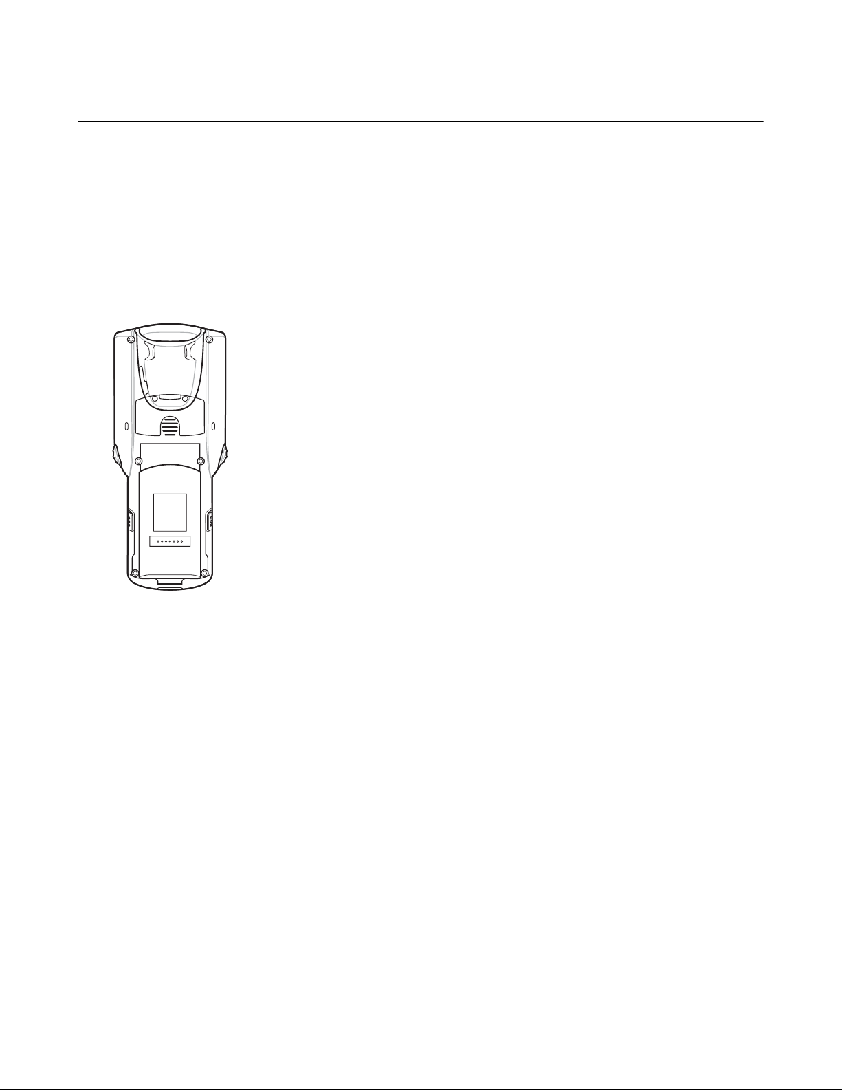
Figure 6: Bottom View
15
16
11
11
10
13
12
14
Getting Started | 19
Table 2: Features - Back View
Number Item Function
10 Stylus Silo Holds the stylus securely in the handle.
11 Speakers Provides audio output for video and music playback.
12 Trigger Initiates data capture.
13 Headset Jack Connects to headsets (2.5 mm plug).
14 Scan LED Indicates data capture functionality.
15 Battery Release
Release the battery from the device.
Buttons
16 Battery Provides power for operating the device.
MN000886A01-B | April 2015

4
3
1
1
5
6
7
8
9
2
20 | Getting Started
MC32N0–R Features
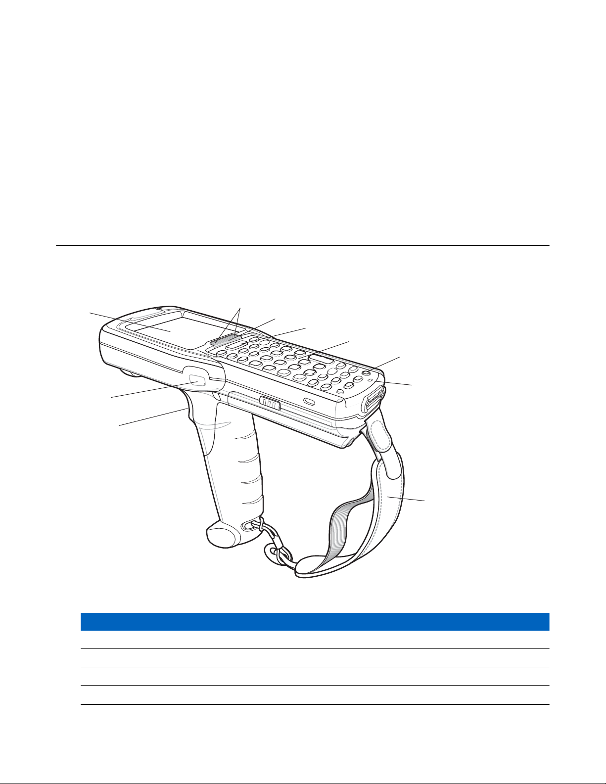
Figure 7: Front View
Table 3: Features - Front View
Number Item Function
1 Scan LED Indicates decode functionality. Light green indicating a successful decode.
2 Beeper Provides audio notifications.
3 Display Displays all information needed to operate the MC32N0–R.
4 Scan Button Initiates data capture.
5 Power Button
On Android devices: Press and hold to turn on the MC32N0-R. Press to
turn on or off the screen. Press and hold to select one of these options:
• Power off - Turn off the MC32N0-R.
• Reset - Reboot the MC32N0-R when software stops responding.
• Airplane mode - Disable all wireless connections.
• Battery swap - Places the device in Battery Swap mode when replacing the battery.
• Silent mode - All notifications are disabled except for alarms.
On WinCE devices: Press to display power option:
Table continued…
April 2015 | MN000886A01-B

Number Item Function
18
17
16
14
12
10
14
11
12
15
13
• Suspend (Sleep mode) – Places the device in sleep mode when not using the device for a period of time.
• Battery Swap – Places the device in Battery Swap mode when replacing the battery.
• Cancel – Close window and cancel operation.
6 Microphone Use for making voice recordings.
7 Keypad Use to enter data and navigate on screen functions.
8 Charging LED Indicates the battery charge state while charging.
9 Rotating Turret Rotate for easy scanning positions.
Figure 8: Back View
Getting Started | 21
Table 4: Features - Back View
Number Item Function
10 Exit Window Provides data capture using the laser scanner.
11 Stylus Use to select items on the screen.
12 Scan Button Initiates data capture.
13 Stylus Holder Holds the stylus securely in the handstrap.
14 Battery Release
Release the battery from the device.
Buttons
15 Battery Provides the MC32N0-R with operating power.
16 Handstrap Use for securely holding the device.
17 Speaker Provides audio output for video and music playback.
18 Headset Jack Connects to headsets (2.5 mm jack).
MN000886A01-B | April 2015

Position Stop
Position Stop
Position Stop
4
2
1
3
5
6
7
8
22 | Getting Started
Rotating Scan Turret
The MC32N0–R features a Rotating Turret with three position stops. This feature offers greater scanning flexibility.
Caution: Do not try to rotate the turret past the side position stops. Damage to device may occur.
Figure 9: Rotating Turret
MC32N0–S Features
Figure 10: Front View
April 2015 | MN000886A01-B

Getting Started | 23
Table 5: Features - Front View
Number Item Function
1 Beeper Provides audio notifications.
2 Display Displays all information needed to operate the MC32N0–R.
3 Scan LED Indicates decode functionality. Light green indicating a successful decode.
4 Scan Button Initiates data capture.
5 Power Button
6 Microphone Use for making voice recordings.
7 Keypad Use to enter data and navigate on screen functions.
8 Charging LED Indicates the battery charge state while charging.
On Android devices: Press and hold to turn on the MC32N0-S. Press to
turn on or off the screen. Press and hold to select one of these options:
• Power off - Turn off the MC32N0-S.
• Reset - Reboot the MC32N0-S when software stops responding.
• Airplane mode - Disable all wireless connections.
• Battery swap - Places the device in Battery Swap mode when replacing the battery.
• Silent mode - All notifications are disabled except for alarms.
On WinCE devices: Press to display power option:
• Suspend (Sleep mode) – Places the device in sleep mode when not using the device for a period of time.
• Battery Swap – Places the device in Battery Swap mode when replacing the battery.
• Cancel – Close window and cancel operation.
MN000886A01-B | April 2015

17
16
15
13
11
9
12
10
13
11
14
24 | Getting Started
Figure 11: Back View
Table 6: Features - Back View
Number Item Function
9 Exit Window Provides data capture using the imager.
10 Stylus Use to select items on the screen.
11 Scan Button Initiates data capture.
12 Stylus Holder Holds the stylus securely in the handstrap.
13 Battery Release
Release the battery from the device.
Buttons
14 Battery Provides the MC32N0-S with operating power.
15 Handstrap Use for securely holding the device.
16 Speaker Provides audio output for video and music playback.
17 Headset Jack Connects to headset (2.5 mm jack).
Unpacking
Carefully remove all protective material from the MC32N0 and save the shipping container for later storage and
shipping.
Verify the following items are in the box:
• MC32N0
• Lithium-ion battery
• Quick Start Guide
• Regulatory Guide.
Inspect the equipment for damage. If any equipment is missing or damaged, contact the Zebra Support Center
immediately. See Service Information on page 15
for contact information.
April 2015 | MN000886A01-B

Getting Started | 25
Setup
To start using the MC32N0 for the first time:
• Install a microSD card (optional)
• Install the battery
• Charge the
• Power on the MC32N0.
Installing a microSD Card
The microSD card slot provides secondary non-volatile storage. The slot is located under the battery pack. Refer to
the documentation provided with the card for more information, and follow the manufacturer’s recommendations for
use.
Procedure:
MC32N0
Caution: Follow proper electrostatic discharge (ESD) precautions to avoid damaging the microSD card.
Proper ESD precautions include, but are not limited to, working on an ESD mat and ensuring that the
operator is properly grounded.
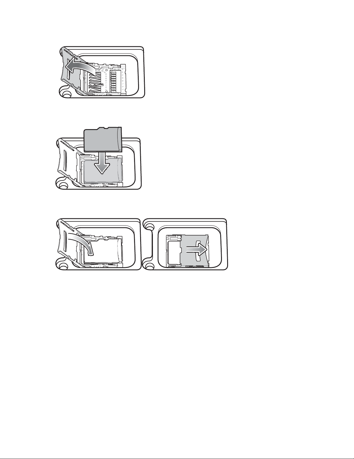
1 Remove the microSD card cover.
Figure 12: Remove microSD Card Cover
2 Slide the microSD card holder down to unlock.
Figure 13: Unlock microSD Card Holder
3 Lift the microSD card holder.
MN000886A01-B | April 2015
26 | Getting Started
Figure 14: Lift microSD Card Holder
4 Place the microSD card into the contact area.
Figure 15: Install microSD Card
5 Close the microSD card holder and slide the microSD card holder up to lock.
Figure 16: Lock microSD Card Holder
6 Replace the microSD card cover and ensure that it is installed properly.
Installing the MC32N0-G Battery
To install the battery:
Procedure:
1 Align the battery into the battery compartment.
April 2015 | MN000886A01-B
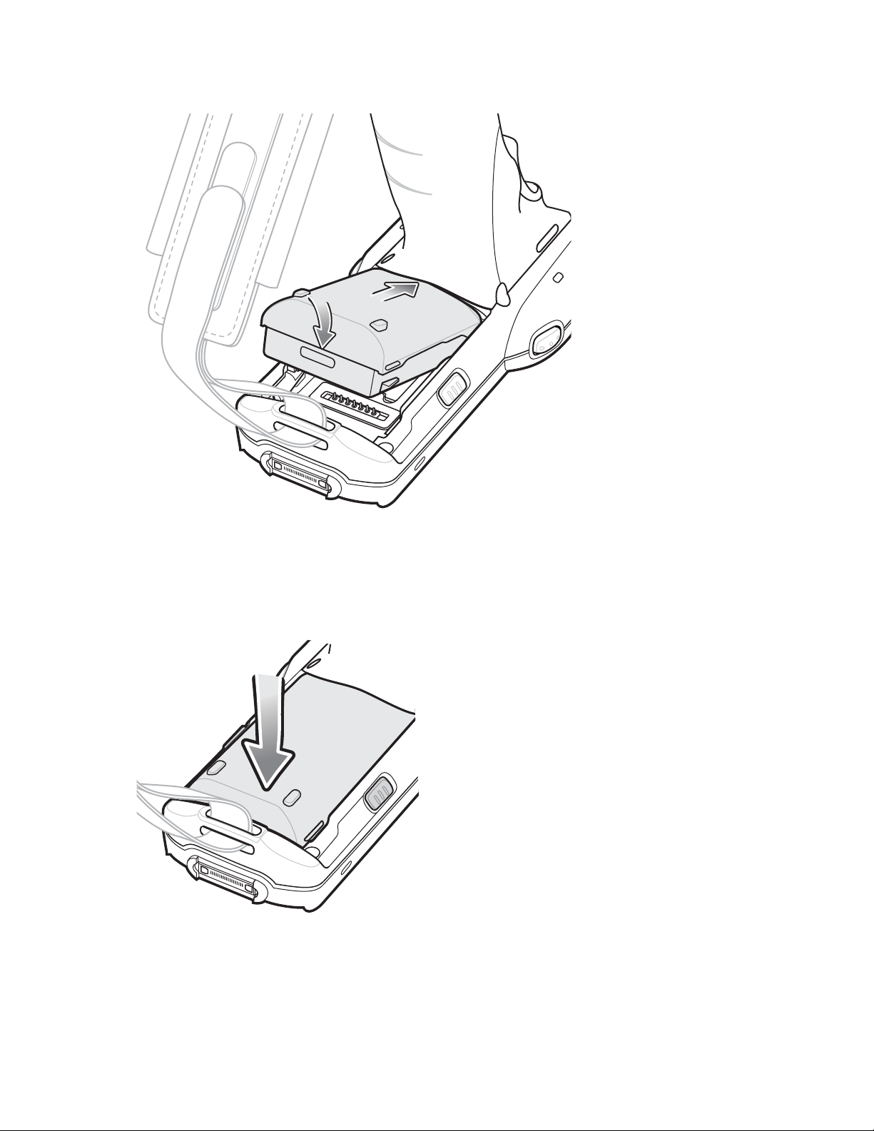
Figure 17: Inserting the Battery
Getting Started | 27
2 Rotate the bottom of the bottom into the battery compartment.
3 Press battery down firmly. Ensure that both battery release buttons on the sides of the MC32N0 return to the home
position.
Figure 18: Press Battery Down
4 Press the Power button to turn on the device.
Installing the MC32N0–R/S Battery
Procedure:
1 Loosen the handstrap.
MN000886A01-B | April 2015

28 | Getting Started
2 Align the top of the battery into the battery compartment.
Figure 19: Inserting the Battery
3 Rotate the bottom of the bottom into the battery compartment.
4 Press battery down firmly. Ensure that both battery release buttons on the sides of the MC32N0 return to the home
position.
Figure 20: Press Battery Down
5 Tighten the handstrap.
6 Press the Power button to turn on the device.
April 2015 | MN000886A01-B

Getting Started | 29
Charging the Battery
Caution: Ensure that you follow the guidelines for battery safety described in Battery Safety Guidelines on
page 145.
Use the mobile computer cradles, cables and spare battery chargers to charge the mobile computer main battery.
The main battery can be charged before insertion into the mobile computer or after it is installed. There are two main
batteries for the MC32N0, the Standard Battery (1X) and the Extended Life Battery (2X). The standard capacity
battery ships from the factory in all MC32N0-R configurations. The Extended Life Battery ships from the factory in
all MC32N0-S and MC32N0-G configurations. To install an Extended Life Battery in the MC32N0-R configurations,
purchase an Extended Life Battery. Use one of the spare battery chargers to charge the main battery (out of the mobile
computer) or one of the cradles to charge the main battery while it is installed in the mobile computer.
Before using the mobile computer for the first time, fully charge the main battery until the amber Charge LED
Indicator remains lit (see Table 7: LED Charge Indicators on page 29 for charge status indications). The
Battery fully charges in less than five hours and the Extended Life Battery fully charges in less than eight hours.
The MC32N0 retains data in memory for at least five minutes when the mobile computer’s main battery is removed
or fully discharged.
When the main battery reaches a very low battery state, the battery retains data in memory for at least 36 hours.
Batteries must be charged within the 0° to +40° C (32° to 104° F) ambient temperature range.
Standard
The following accessories can be used to charge batteries:
• Cradles (and a power supply):
- Single Slot Serial/USB Cradle with Battery Adapter
- Four Slot Cradles.
• Cables (and a power supply):
- USB Client Charge Cable
- Serial (RS232) Charge Cable.
• Spare Battery Chargers (and a power supply):
- Four Slot Spare Battery Charger
- Universal Battery Charger (UBC) Adapter with Battery Adapter.
To charge the mobile computer using the cradles:
1. Insert the mobile computer into a cradle. See Accessories on page 121 for accessory setup.
2. The mobile computer starts to charge automatically. The amber Charge LED Indicator indicates the charge status.
See the table below for charging indications.
To charge the mobile computer using the cables:
1. Connect the MC32N0 Communication/Charge Cable to the appropriate power source and connect to the mobile
computer. See Accessories on page 121 for accessory setup.
2. The mobile computer starts to charge automatically. The amber Charge LED Indicator indicates the charge status.
Table 7: LED Charge Indicators
Status Indications
Off
MC32N0 is not charging.
MC32N0 is not inserted correctly in the cradle.
MC32N0 is not connected to a power source.
Table continued…
MN000886A01-B | April 2015
30 | Getting Started
Status Indications
Charger or cradle is not powered.
Slow Blinking Amber MC32N0 is charging.
Solid Amber Charging complete. Note: When the battery is initially inserted in the mobile
computer, the amber LED flashes once if the battery power is low.
Fast Blinking Amber Charging error, e.g.:
• Temperature is too low or too high.
• Charging has gone on too long without completion (typically eight hours).
Charging Temperature
Charge batteries in ambient temperatures from 0 °C to 40 °C (32 °F to 104 °F) or up to 45 °C (113 °F) as reported by
the battery. To view the battery temperature
Information.
Note that charging is intelligently controlled by the MC32N0. To accomplish this, for small periods of time, the
MC32N0 or accessory alternately enables and disables battery charging to keep the battery at acceptable
temperatures. The MC32N0 or accessory indicates when charging is disabled due to abnormal temperatures via its
LED.
on Android devices, touch > About device > Battery
Charging Spare Batteries
See Accessories on page 121 for information on using accessories to charge spare batteries.
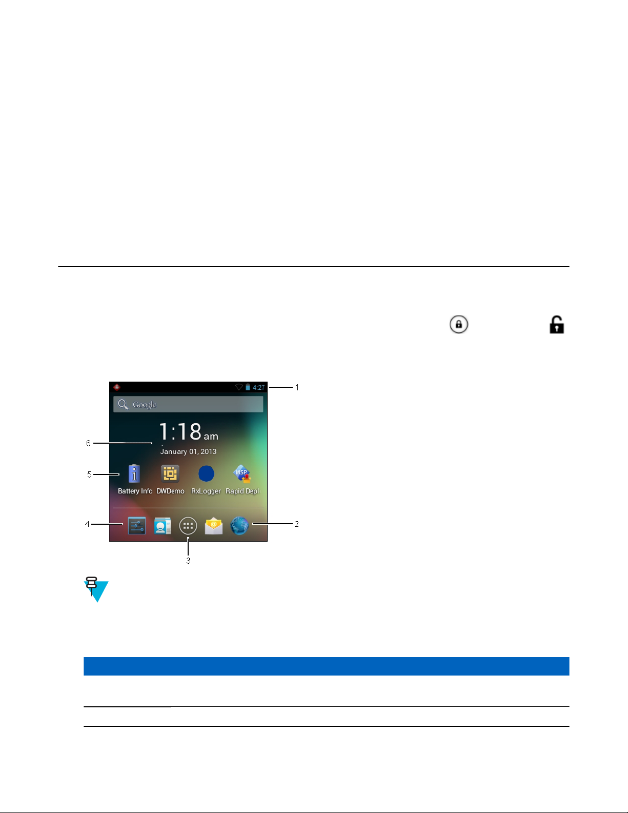
Replacing the MC32N0-G Battery
Procedure:
1 Press the Power button until the menu appears.
2 On Android device, touchTouch Battery swap. Wait for the Scan LED to light red and then turn off.
3 On WinCE device, touch Safe Battery Swap
4 Push in the two Battery Release buttons.
. Wait for the Scan LED to light red and then turn off.
April 2015 | MN000886A01-B
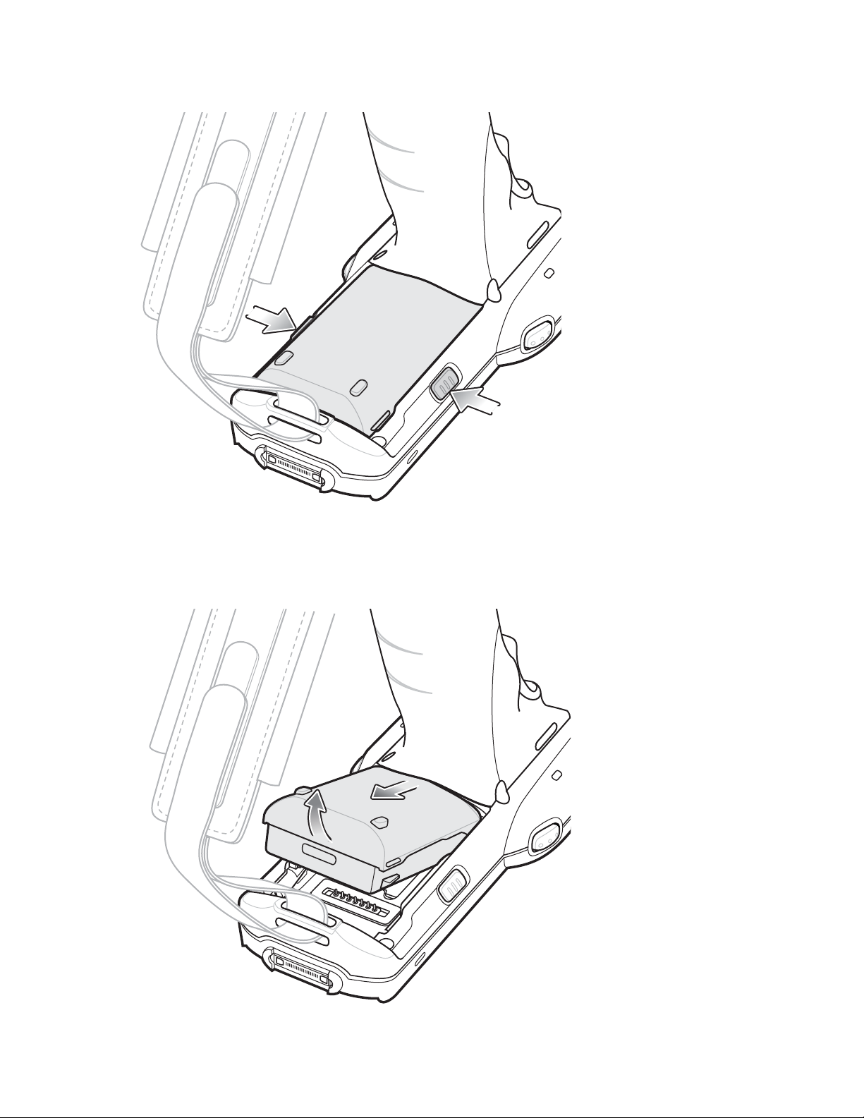
Figure 21: Release Battery
Getting Started | 31
The battery ejects slightly.
5 Remove the battery from the battery compartment.
Figure 22: Remove Battery
MN000886A01-B | April 2015

32 | Getting Started
6 Align the battery into the battery compartment.
Figure 23: Inserting the Battery
7 Rotate the bottom of the bottom into the battery compartment..
8 Press battery down firmly. Ensure that both battery release buttons on the sides of the MC32N0 return to the home
position.
Figure 24: Press Battery Down
9 Press the Power button to turn on the device.
April 2015 | MN000886A01-B

Replacing the MC32N0-R/S Battery
Procedure:
1 Press the Power button until the menu appears.
2 On Android device, touch Power Off and then OK.
3 On WinCE device, touch Safe Battery Swap
4 Loosen the handstrap and lift to access the battery.
5 Push in the two Battery Release buttons.
Figure 25: Release Batery
. Wait for the Scan LED to light red and then turn off.
Getting Started | 33
The battery ejects slightly.
6 Lift the battery out of the battery compartment.
MN000886A01-B | April 2015

34 | Getting Started
Figure 26: Remove Battery
7 Align the top of the battery into the battery compartment.
Figure 27: Inserting the Battery
8 Rotate the bottom of the bottom into the battery compartment.
9 Press battery down firmly. Ensure that both battery release buttons on the sides of the MC32N0 return to the home
position.
April 2015 | MN000886A01-B

Figure 28: Press Battery Down
10 Tighten the handstrap.
11 Press the Power button to turn on the device.
Getting Started | 35
Battery Management on Android™ Devices
Note:
Prior to checking the battery charge level, remove the MC32N0 from any AC power source (cradle or
cable).
To check the charge status of the main battery, touch > About device > Status.
Battery status indicates that the battery is discharging and Battery level lists the battery charge (as a percentage of
fully charged).
Monitor Battery Usage
The Battery Use screen lists which applications consume the most battery power. Also use it to turn off applications
that were downloaded if they are consuming too much power.
Touch > Battery.
MN000886A01-B | April 2015

36
| Getting Started
Figure 29: Battery Use Screen
The Battery Use screen lists the applications using the battery. The discharge graph at the top of the screen shows the
rate of battery discharge since last charged (short periods of time when connected to a charger are shown as thin green
lines at the bottom of the chart), and how long it has been running on battery power.
Touch an application in the Battery Use screen to display details about its power consumption. Different applications
display different information. Some applications include buttons that open screens with settings to adjust power use.
Low Battery Notification
When the battery charge drops below 23% (Standard Capacity Battery) or 11% (Extended Capacity Battery), the
MC32N0 displays a notice to connect the MC32N0 to power.
Figure 30: Low Battery Notification Screen
The user should replace the battery or charge the MC32N0 using one of the charging accessories.
When the battery charge drops below 17% (Standard Capacity Battery) or 8% (Extended Capacity Battery), the
MC32N0 goes into critical suspend mode to save data. The screen turns off. If the Power button is pressed, the Right
LED flashes amber.
The user must replace the battery or charge the MC32N0 using one of the charging accessories to retain data.
Battery Optimization
Observe the following battery saving tips:
• Leave the MC32N0 connected to AC power at all times when not in use.
• Set the screen to turn off after a short period of non-use.
• Reduce the screen brightness.
April 2015 | MN000886A01-B

Getting Started | 37
• Turn off all wireless radios when not in use.
• Turn off automatic syncing for Email, Calendar, Contacts, and other applications.
• Use the Power Control widget to check and control the status of radios, the screen brightness, and syncing.
• Minimize use of applications that keep the MC32N0 from suspending, for example, music and video applications.
Battery Management on WinCE Devices
Note:
Prior to checking the battery charge level, remove the MC32N0 from any AC power source (cradle or
cable).
To check the charge status of the main battery, touch
Figure 31: Power Settings — Battery Tab
Battery Power remaining lists the battery charge (as a percentage of fully charged).
> Settings > Control Panel > Power.
Low Battery Notification
When the battery charge drops below 15% (default), the MC32N0 displays a notice to connect the MC32N0 to power.
Figure 32: Low Battery Notification Screen
The user should replace the battery or charge the MC32N0 using one of the charging accessories.
When the battery charge drops below 10%, the MC32N0 goes into critical suspend mode to save data. The screen
turns off. If the Power button is pressed, the Right LED flashes amber.
The user must replace the battery or charge the MC32N0 using one of the charging accessories to retain data.
MN000886A01-B | April 2015

38 | Getting Started
Battery Optimization
Observe the following battery saving tips:
• Leave the MC32N0 connected to AC power at all times when not in use.
• Set the screen to turn off after a short period of non-use.
• Reduce the screen brightness.
Turn off all wireless radios when not in use.
•
• Turn off automatic syncing for Email, Calendar, Contacts, and other applications.
• Use the Power Control widget to check and control the status of radios, the screen brightness, and syncing.
• Minimize use of applications that keep the MC32N0 from suspending, for example, music and video applications.
Connecting a Wired Headset
To connect a wired headset to the MC32N0:
Figure 33: Connect Headset to MC32N0–R/S
Figure 34: Connect Headset to MC32N0–G
Using a Bluetooth Headset
You can use a Bluetooth headset for audio communication when an audio enabled application is used. See Bluetooth
on page 74for information on connecting a Bluetooth device to the mobile computer. Ensure that the mobile
computer’s volume is set appropriately before putting the headset on. When a Bluetooth headset is connected the
speaker is muted.
Note: If the mobile computer goes into suspend mode the Bluetooth connection is disabled and the mobile
computer automatically switches to speakerphone mode.
April 2015 | MN000886A01-B
Chapter
2
39 | Using the MC32N0 with Android
™
Using the MC32N0 with Android
This chapter describes the screens, status and notification icons, and controls on the MC32N0, and provides basic
instructions for using the MC32N0.
™
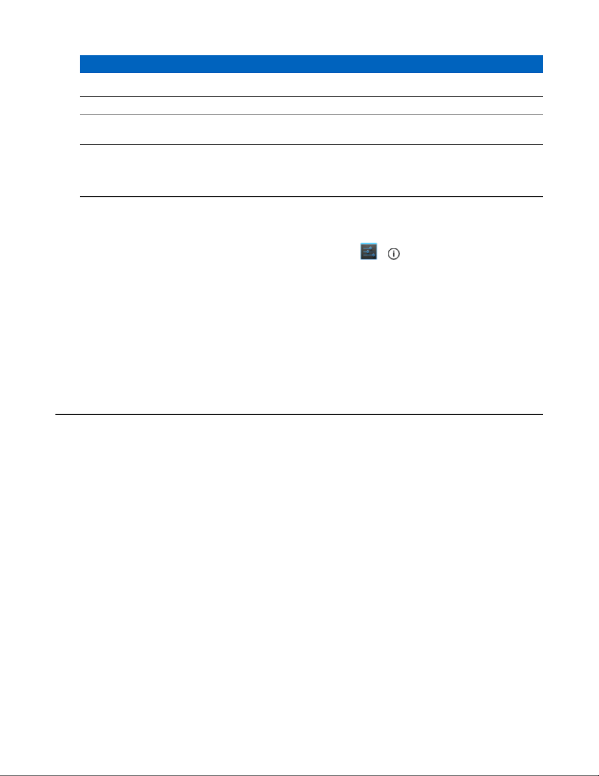
Home Screen
The Home screen displays when the MC32N0 turns on. Depending upon the configuration, the Home screen might
appear different. Contact your system administrator for more information.
After a suspend or screen time-out, the Home screen displays with the lock sliders. Slide
to unlock the screen. For screen locking information see Un-Locking the Screen on page 62.
Figure 35: Home Screen
to the right toward
Note: The Home screen icons can be configured by the user and may look different than shown.
The Home screen consists of the following:
Table 8: Home Screen Items
Item Description
1 — Status Bar Displays the time, status icons (right side), and notification icons (left side). For more informa-
on page 42.
Table continued…
2 — Browser Icon
tion see Status Icons on page 40 and Managing Notifications
Opens the Browser application.
MN000886A01-B | April 2015

40 | Using the MC32N0 with Android
Item Description
3 — All Apps Icon Opens the APPS window.
4 — Settings Icon Opens the Settings window.
5 — Shortcut Icons Opens applications installed on the MC32N0. See Application Shortcuts and Widgets on page
43 for more information.
6 — Widgets Launches stand-alone applications that run on the Home screen. See Application Shortcuts and
Widgets on page 43
The Home screen provides four additional screens for placement of widgets and shortcuts. Swipe the screen left or
right to view the additional screens.
™
for more information.
Status Bar
The Status bar displays the time, notification icons (left side) and status icons (right side).
Figure 36: Notification and Status Icons
1 Notifications icons
2 Status icons
If there are more notifications than can fit in the Status bar, displays indicating that more notifications exist. Open
the Notifications panel to view all notifications and status.
Status Icons
Table 9: Status Icons
Icon Description
Indicates that Bluetooth is on.
Indicates that the device is connected to another Bluetooth device.
Indicates that the Alarm is active.
Indicates that all sounds except media and alarms are silenced and vibrate mode is active.
Table continued…
April 2015 | MN000886A01-B
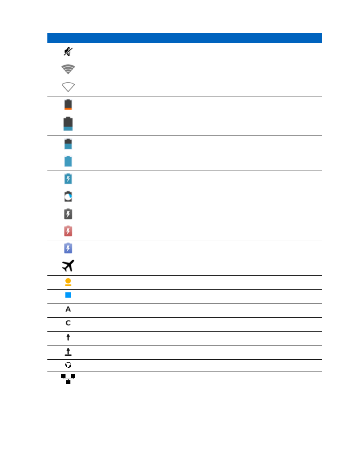
Icon Description
Indicates that the audio is silenced.
Connected to a Wi-Fi network.
No Wi-Fi signal.
Indicates that the battery charge is very low.
Indicates that the battery charge is low.
Indicates that the battery is partially drained.
Indicates that the battery is fully charged.
Indicates that the battery is charging.
Using the MC32N0 with Android™ | 41
Indicates that the MC32N0 is calculating the battery capacity level.
Indicates an unknown charging error.
Indicates that the battery temperature is nearing the high for charging to occur.
Indicates that the battery temperature is nearing the low for charging to occur.
Indicates that the Airplane Mode is active. All radios are turned off.
Indicates that the Orange key is locked.
Indicates that the Blue key is pressed.
Indicates that the ALT key is pressed.
Indicates that the CTRL key is pressed.
Indicates that the Shift key is pressed.
Indicates that the Shift key is locked.
Indicates that a wired headset is connected to the MC32N0.
Connected to an Ethernet network.
MN000886A01-B | April 2015

42
| Using the MC32N0 with Android
Notification Icons
Table 10: Notification Icons
Icon Description
Indicates that more notifications are available for viewing.
Indicates that data is syncing.
Indicates an upcoming event.
Indicates that a problem with sign-in or sync has occurred.
Indicates that the device is uploading data.
Indicates that the microSD card is almost full.
™
Indicates that the device is downloading data when animated and download is complete when static.
Indicates that the device is connected via USB cable.
Indicates that the device is connected to a virtual private network (VPN).
Preparing microSD card.
Indicates that USB debugging is enabled on the device.
Screenshot captured.
Error capturing screenshot.
Indicates that the MultiUser feature is enabled.
Indicates that a new user is logging in.
Managing Notifications
Notification icons report the arrival of new messages, calendar events, and alarms, as well as ongoing events. When a
notification occurs, an icon appears in the Status bar with a brief description. See Notification Icons on page 42 for a
list of possible notification icons and their description. Open the Notifications panel to view a list of all the
notifications.
To open the Notification panel, drag the Status bar down from the top of the screen.
April 2015 | MN000886A01-B
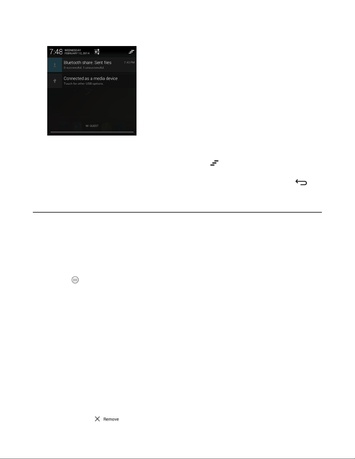
Using the MC32N0 with Android™ | 43
Figure 37: Notification Panel
To respond to a notification, open the Notifications Panel and then touch a notification. The Notifications Panel closes
and the subsequent activity is dependent on the notification.
To clear all notifications, open the Notifications Panel and then touch . All event-based notifications are removed.
Ongoing notifications remain in the list.
To close the Notification Panel, drag the bottom of the Notifications Panel to the top of the screen or press .
Application Shortcuts and Widgets
Application shortcuts placed on the Home screen allow quick and easy access to applications. Widgets are selfcontained applications placed on the Home screen to access frequently used features.
Adding an Application or Widget to the Home Screen
Procedure:
1 Go to the desired Home screen.
2
Touch .
3 Swipe right, if necessary, to find the application icon or widget.
4 Touch and hold the icon or widget until the Home screen appears.
5 Position the icon on the screen and then release.
Moving Items on the Home Screen
Procedure:
1 Touch and hold the item until it floats on the screen.
2 Drag the item to a new location. Pause at the edge of the screen to drag the item onto an adjacent Home screen.
3 Lift finger to place the item on the Home screen.
Removing an App or Widget from the Home Screen
Procedure:
1 Go to the desired Home screen.
2 Touch and hold the application shortcut or widget icon until it floats on the screen.
3
Drag the icon to on the top of the screen and then release.
MN000886A01-B | April 2015

44 | Using the MC32N0 with Android
™
Folders
Use Folders to organize similar applications together. Touch the folder to open and display items in the folder.
Creating Folders
Procedure:
1 Go to the desired Home screen.
2 Place at least two application shortcuts on the Home screen.
3 Touch and hold a shortcut until it floats on the screen.
4 Move the icon over another icon. A blue circle appears around the icons.
Figure 38: Stacked Shortcut Icons
5 Lift finger to stack the icons. The shortcut icons appear over a black circle.
Figure 39: Unnamed Folder
Naming Folders
Procedure:
1 Touch the folder.
Figure 40: Open Folder
2 Touch the title area and enter a folder name using the keyboard.
3 Touch Done.
4 Touch anywhere on the Home screen to close the folder. The folder name appears under the folder.
Figure 41: Renamed Folder
Removing a Folder
Procedure:
1 Touch and hold the folder icon until it enlarges and the device vibrates.
April 2015 | MN000886A01-B

2
Drag the icon to and release.
Home Screen Wallpaper
Note: Use of Live Wallpaper may reduce battery life.
Change the Home Screen Wallpaper
Procedure:
1 Touch and hold on the Home screen until the Choose Wallpaper from menu appears.
2 Touch Gallery, Live wallpapers or Wallpapers.
• Gallery - Select to use an image stored on the device.
• Live wallpapers - Select to use an animated wallpaper image.
• Wallpapers - Select to use a wallpaper image.
3 Touch Save or Set wallpaper.
Using the MC32N0 with Android™ | 45
Using the Touchscreen
Use the screen to operate the device.
• Touch - Touch to:
- select items on the screen
- type letters and symbols using the on-screen keyboard
- press on-screen buttons.
• Touch and Hold
- an item on the Home screen to move it to a new location or to the trash.
- an item in the All Apps screen to create a shortcut on the Home screen.
- the Home screen to change the Home screen wallpaper.
• Drag - Touch and hold an item for a moment and then move finger on the screen until reaching the new position.
• Swipe - Move finger up and down or left and right on the screen to:
- unlock the screen
- view additional Home screens
- view additional application icons in the All Apps screen
- view more information on an application’s screen.
• Double-tap - Tap twice on a web page, map, or other screen to zoom in and out.
- Touch and hold:
MN000886A01-B | April 2015

46 | Using the MC32N0 with Android
™
Using the On-screen Keyboard
Use the on-screen keyboard to enter text in a text field. To configure the keyboard settings, touch > and then
select Android keyboard settings.
Editing Text
Edit entered text and use menu commands to cut, copy, and paste text within or across applications. Some
applications do not support editing some or all of the text they display; others may offer their own way to select text.
Entering Numbers, Symbols and Special Characters
To enter numbers and symbols:
• Touch and hold one of the top-row keys until a menu appears then select a number. Keys with alternate characters
display an ellipsis ( ... ) below the character.
• Touch and hold the Shift key with one finger, touch one or more capital letters or symbols to enter them, and then
lift both fingers to return to the lowercase keyboard.
•
Touch to switch to the numbers and symbols keyboard.
•
Touch the
key on the numbers and symbols keyboard to view additional symbols.
To enter special characters, touch and hold a number or symbol key to open a menu of additional symbols.
A larger version of the key displays briefly over the keyboard.
•
•
Keys with alternate characters display an ellipsis ( ... ) below the character.
Applications
The APPS screen displays icons for all installed applications. The table below lists the applications installed on the
MC32N0. Refer to the MC32N0 Integrator Guide for information on installing and uninstalling application.
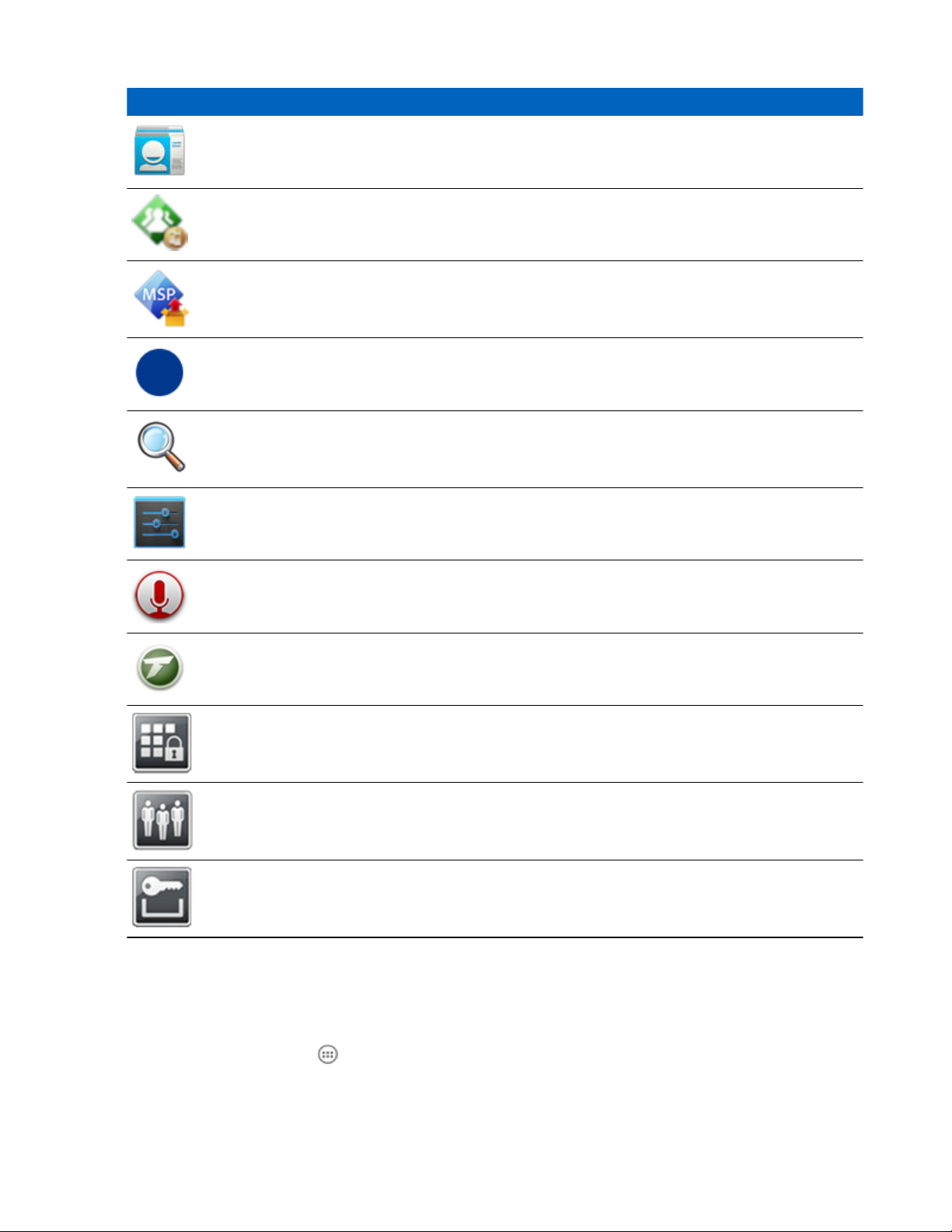
Table 11: Applications
Icon Description
Battery Info – Displays the Battery Information screen.
Bluetooth Pairing – Use to pair the RS507 Hands-free imager with the MC32N0 by scanning a
bar code.
Browser - Use to access the Internet or intranet.
April 2015 | MN000886A01-B
Table continued…

Icon Description
Calculator - Provides the basic and scientific arithmetic functions.
Calendar - Use to manage events and appointments.
Clock - Use to schedule alarms for appointments or as a wake-up.
DataWedge - Enables data capture using the camera or optional scanner.
Downloads - lists all downloads files.
Using the MC32N0 with Android™ | 47
DWDemo - Provides a way to demonstrate the data capture features using the Linear Imager. See
DataWedge Demonstration on page 57 for more information.
Email - Use to send and receive email.
File Browser - Organize and manage files on the MC32N0. See File Browser
more information.
Gallery - Use to view photos stored on the microSD card. For more information, see Gallery on
page 51 for more information.
MLog Manager - Use to capture log files for diagnostics. See MLog Manager on page 58 for
more information.
Mobi Control Stage – Opens the Mobi Control Stage application to stage the MC32N0.
MSP Agent - Enables management of the MC32N0 from an MSP server. Requires the purchase
of an appropriate MSP client license per device to suit the level of management functionality required.
on page 49
for
Music - Play music stored on the microSD card.
Table continued…
MN000886A01-B | April 2015
48 | Using the MC32N0 with Android
Icon Description
People - Use to manage contact information. People on page 50 for more information.
PTT Express – Use to launch the PTT Express client for Voice over IP (VoIP) communication.
Rapid Deployment - Allows the MC32N0 to stage a device for initial use by initiating the de-
ployment of settings, firmware and software. Requires the purchase of an MSP client license per
device.
RxLogger – Use to diagnose device and application issues. See the MC32N0 Integrator Guide for
more information.
Search - Use the Google search engine to search the Internet and the MC32N0.
™
Settings - Use to configure the MC32N0.
Sound Recorder - Use to record audio.
Terminal Emulation – Opens Wavelink Terminal Emulation application.
AppLock Administrator - Use to configure the Application Lock feature. This icon appears after
the optional MX feature is installed.
MultiUser Administrator - Use to configure the MultiUser feature. This icon appears after the
optional MX feature is installed.
Secure Storage Administrator - Use to configure the Secure Storage feature. This icon appears
after the optional MX feature is installed.
Accessing Applications
All applications installed on the device are accessed using the APPS window.
Procedure:
1
On the Home screen touch . The APPS window displays.
April 2015 | MN000886A01-B

Using the MC32N0 with Android™ | 49
Figure 42: APPS Window
2 Slide the APPS window left or right to view more application icons. Touch an icon to open the application.
Note: See Application Shortcuts and Widgets on page 43 for information on creating a shortcut on the
Home screen.
Switching Between Recent Applications
Procedure:
1
Press and hold . A window appears on the screen with icons of recently used applications.
Figure 43: Recently Used Applications
2 Slide the window up and down to view all recently used applications.
3 Swipe left or right to remove application from the list and force close the application.
4 Touch an icon to open it or press to return to the current screen.
File Browser
Use the File Browser application to view and mange files on the device.
To open File Browser, touch
> .
MN000886A01-B | April 2015

50 | Using the MC32N0 with Android
Figure 44: File Browser Screen
The address bar (1) indicates the current folder path. Touch the current folder path to manually enter a path and folder
name.
™
Use (2) to select multiple files/folder.
Use
Use (4) to view the microSD card root folder.
Use (5) to view the previous folder or to exit the application.
Touch and hold an item to perform an operation on that item. Select one of the options from the File Operations
menu:
• Information - View detailed information about the file or folder.
• Move - Move the file or folder to a new location.
• Copy - Copy the select file.
• Delete - Delete the selected file.
• Rename - Rename the select file.
• Open as - Open the selected file as a specific file type.
• Share - Share the file with other devices.
(3) to view the internal storage root folder.
People
Use the People application to manage contacts.
From a Home or Apps screen, touch
the top of the screen: Groups , All contacts , and Favorites. Touch the tabs to change how to view the contacts. Swipe
up or down to scroll through the lists.
. People opens to the main list of contacts. View contacts in three ways at
Adding People
Procedure:
1
In the People application, touch
2 If there are more than one account with contacts, touch the one to use.
3 Type the contact’s name and other information. Touch a field to start typing, and swipe down to view all
categories.
April 2015 | MN000886A01-B
.

Using the MC32N0 with Android™ | 51
4 To add more than one entry for a category – for example, to add a work address after typing a personal address –
touch Add new for that field. To open a menu with preset labels, such as Home or Work for an email address,
touch the label to the right of the item of contact information. Or, to create your own label, touch Custom in the
menu.
5 Touch Done.
Editing People
Procedure:
1
In the People application, touch tab.
2 Touch a person to edit.
3
Press .
4 Touch Edit.
5 Edit the contact information.
6 Touch Done.
Deleting People
Procedure:
1
In the People application, touch tab.
2 Touch a person to edit.
3
Press .
4 Touch Delete.
5 Touch OK to confirm.
Gallery
Note:
The device supports the following image formats: jpeg, gif, png and bmp.
The device supports the following video formats: H.263, H.264 and MPEG4 Simple Profile.
Use Gallery to:
• view photos
• play videos
• perform basic editing of photos
set photos as wallpaper
•
• set photos as a contact photo
• share photos and videos.
To open the Gallery application, touch
right.
> or in the camera application touch the thumbnail image at the top
Gallery presents all photos and videos stored on the microSD card.
MN000886A01-B | April 2015

52 | Using the MC32N0 with Android
Figure 45: Gallery — Albums
• Touch an album to open it and view its contents. The photos and videos in the album are displayed in
chronological order.
• Touch a photo or video in an album to view it.
•
Touch icon (top left corner) to return to the main Gallery screen.
™
Working with Albums
Albums are groups of images and videos in folders. Touch an album to open it. The photos and videos are listed in a
chronologically ordered grid. The name of the album displays at the top of the screen.
Figure 46: Photos Inside an Album
Swipe left or right to scroll images across the screen.
Share an Album
Procedure:
1
Touch .
2
Touch .
3 Touch and hold an album until it highlights.
4 Touch other albums as required.
5
Touch . The Share menu opens. Touch the application to use to share the selected albums.
April 2015 | MN000886A01-B

6 Follow the instructions within the selected application.
Get Album Information
Procedure:
1
Touch .
2
Touch
3 Touch and hold an album until it highlights.
4
Touch .
5 Touch Details.
.
Deleting an Album
To delete an album and its contents from the microSD card:
Procedure:
1
Touch .
Using the MC32N0 with Android™ | 53
2
Touch
3 Touch and hold an album until it highlights.
4 Check other albums to delete. Ensure that other albums are selected.
5
Touch .
6 In the Delete selected item? menu, touch OK to delete the album.
.
Working with Photos
Use Gallery to view photos on the microSD card and edit and share photos.
Viewing and Browsing Photos
To view a photo:
Procedure:
1
Touch .
2
Touch .
3 Touch an album to open it.
4 Touch a photo.
MN000886A01-B | April 2015

| Using the MC32N0 with Android
54
Figure 47: Photo Example
5 Swipe left or right to view the next or previous photo in the album.
6 Turn the device to view the photo in upright (portrait) or sideways (landscape) orientation. The photo is displayed
(but not saved) in the new orientation.
7 Touch the photo to view the controls.
8 Double-tap the screen to zoom in or pinch two fingers together or spread them apart to zoom in or out.
9 Drag the photo to view parts that are not in view.
™
Rotating a Photo
Procedure:
1 Touch a photo to view the controls.
2
Press .
3 Touch Rotate Left or Rotate Right.
The photo is automatically saved with the new orientation.
Cropping a Photo
Procedure:
1 In Gallery, touch a photo to view the controls.
2
Press .
3 Touch Crop. The blue cropping tool appears.
4 Use the cropping tool to select the portion of the photo to crop.
• Drag from the inside of the cropping tool to move it.
• Drag an edge of the cropping tool to resize it to any proportion.
• Drag a corner of the cropping tool to resize it with fixed proportions.
April 2015 | MN000886A01-B
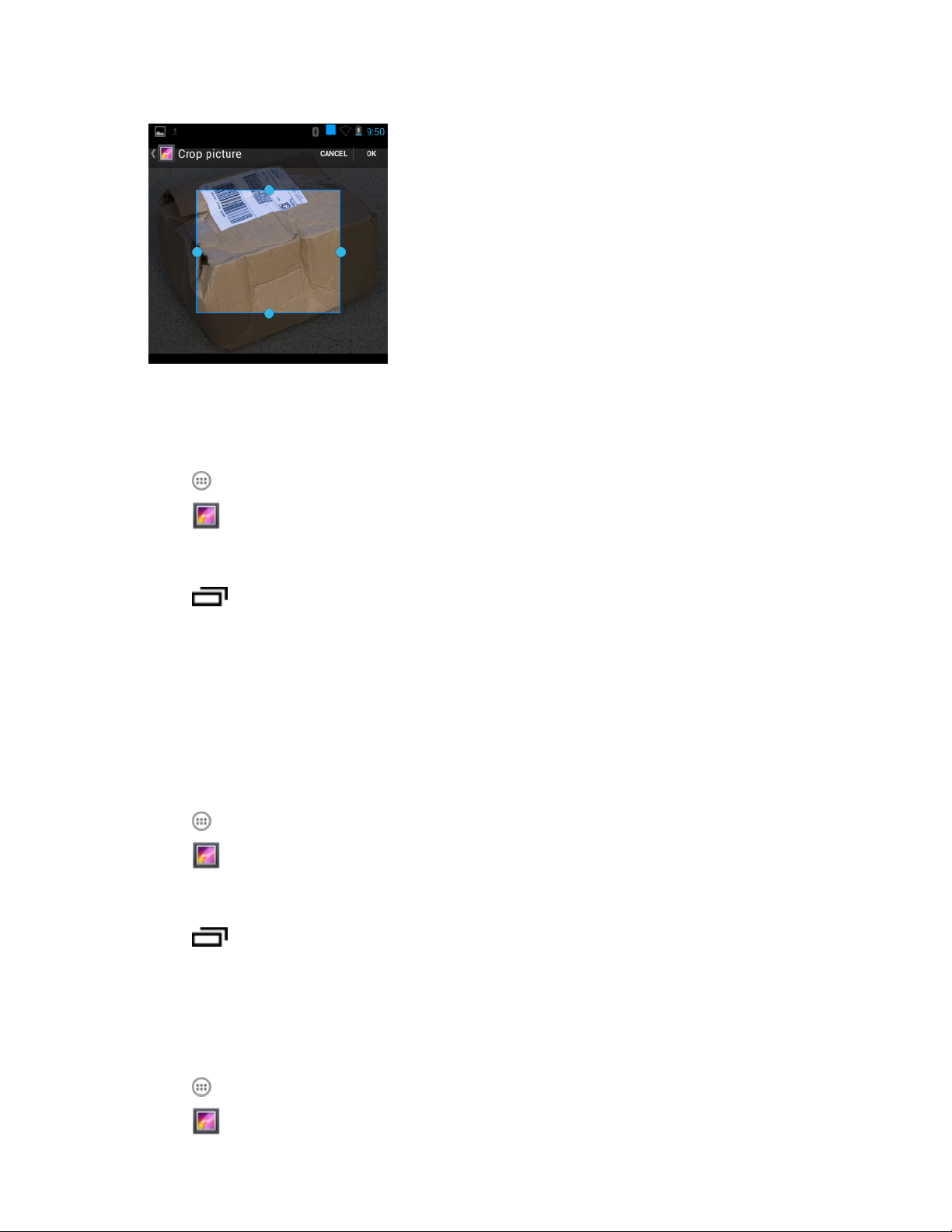
Figure 48: Cropping Tool
5 Touch OK to save a copy of the cropped photo. The original version is retained.
Setting a Photo as a Contact Icon
Procedure:
Using the MC32N0 with Android™ | 55
1
Touch .
2
Touch .
3 Touch an album to open it.
4 Touch the photo to open it.
5
Touch .
6 Touch Set picture as.
7 Touch Contact photo.
8 In the People application, touch a contact.
9 Touch the blue box and crop the photo accordingly.
10 Touch OK.
Get Photo Information
Procedure:
1
Touch .
2
Touch
3 Touch an album to open it.
4 Touch the photo to open it.
5
Touch .
6 Touch Details.
7 Touch Close.
.
Share a Photo
Procedure:
1
Touch .
2
Touch
.
MN000886A01-B | April 2015

56 | Using the MC32N0 with Android
3 Touch an album to open it.
4 Touch a photo to open it.
5
Touch .
6 Touch the application to use to share the selected photo. The application selected opens with the photo attached to
a new message.
™
Deleting a Photo
Procedure:
1
Touch .
2
Touch .
3 Touch an album to open it.
4 Touch a photo to open it.
5
Touch
6 Touch OK to delete the photo.
.
Working with Videos
Use Gallery to view videos on the microSD card and share videos.
Watching Videos
Procedure:
1
Touch .
2
Touch .
3 Touch an album to open it.
4 Touch a video.
5
Touch . The video begins to play.
Figure 49: Video Example
6 Touch the screen to view the playback controls.
April 2015 | MN000886A01-B

Using the MC32N0 with Android™ | 57
Sharing a Video
Procedure:
1
Touch .
2
Touch
3 Touch an album to open it.
4 Touch a video to open it.
5
Touch
6 Touch the application to use to share the selected video. The application selected opens with the video attached to
a new message.
.
. The Share menu appears.
Deleting a Video
Procedure:
1
Touch .
2
Touch
3 Touch an album to open it.
4 Touch a video to open it.
5
Touch .
6 Touch OK.
.
DataWedge Demonstration
Use DataWedge Demonstration to demonstrate data capture functionality.
Figure 50: DataWedge Demonstration Window
Table 12: DataWedge Demonstration Icons
Icon Description
Not applicable.
Table continued…
MN000886A01-B | April 2015
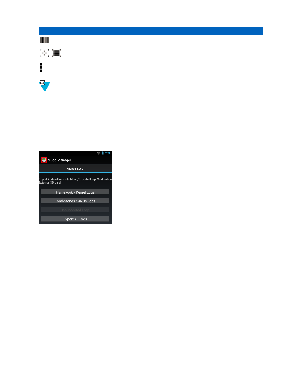
58 | Using the MC32N0 with Android
Icon Description
Indicates that the data capture function is through the imager.
Toggles between normal scan mode and picklist mode when using the imager to capture bar
/
Note:
See the MC32N0 Integrator Guide for information on DataWedge configuration.
Either press a Scan key or touch the yellow scan button in the application to enable data capture. The captured data
appears in the text field below the yellow button.
code data.
Opens a menu to view the application information or to set the application DataWedge profile.
™
MLog Manager
Use MLog Manager to capture log files for diagnostics. See the MC32N0 Integrator Guide for detailed information
on configuring the application.
Figure 51: MLog Manager
Sound Recorder
Use Sound Recorder to record audio messages.
Recordings are saved on the microSD card (if installed) or the Internal Storage and available in the Music application
playlist titled "My Recordings."
April 2015 | MN000886A01-B
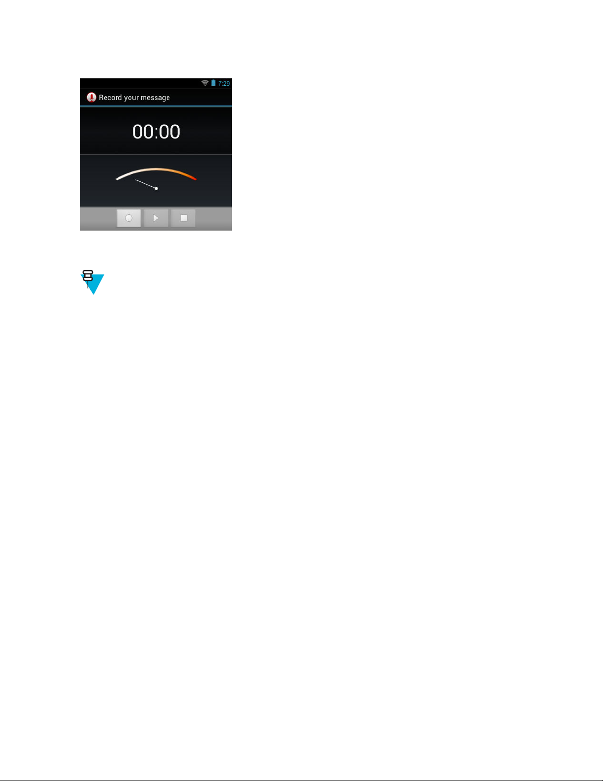
Figure 52: Sound Recorder Application
PTT Express Voice Client
Note:
PTT Express Voice Client creates Push-To-Talk (PTT) communication capability between disparate
enterprise devices. Leveraging existing Wireless Local Area Network (WLAN) infrastructure, PTT Express
delivers simple PTT communication without the need of a voice communication server.
Using the MC32N0 with Android™ | 59
• Group Call: Press and hold the Talk button (yellow Scan button on the MC32N0-G keypad or the right Scan
button on MC32N0-R/S) to start communicating with other voice client users.
• Private Response: Press and release and then press and hold the Talk button to respond to the originator of the
last group call.
PTT Audible Indicators
The following tones provide helpful cues when using the voice client.
• Talk Tone: Double chirp. Plays when the Talk button is depressed. This is a prompt for the user to start talking.
• Access Tone: Single beep. Plays when another user just finished a broadcast or response. The user is now able to
initiate a Group Broadcast.
• Busy Tone: Continuous tone. Plays when the Talk button is depressed and another user is already communicating
on the same talkgroup. Plays after the maximum allowed talk time is reached (60 seconds).
• Network Tone:
- Three increasing pitch beeps. Plays when PTT Express has acquired the WLAN connection and the service is
enabled.
- Three decreasing pitch beeps. Plays when PTT Express has lost the WLAN connection or the service is
disabled.
MN000886A01-B | April 2015

60 | Using the MC32N0 with Android
Figure 53: PTT Express Default User Interface
Table 13: PTT Express Default user Interface Descriptions
Item Description
Notification Icon Indicates the current state of the PTT Express client.
™
Service Indication Indicates the status of the PTT Express client. Options: Service Enabled, Service Disabled
or Service Unavailable.
Previous Profile Button
Talk Group Lists Talk Groups available for PTT communication.
Speaker Icon Mutes and un-mutes the client. If muted, a call cannot be heard and initiated.
Settings Opens the PTT Express Settings screen.
Enable/Disable
Switch
Next Profile Button Scrolls to the next profile screen.
Profile Enable/Disable Checkbox
Profile Name Displays the name of the current profile.
Scrolls to the previous profile screen.
Turns the PTT service on and off.
Indicates that the profile is enabled (checked) or disabled (unchecked).
Enabling PTT Communication
Procedure:
1
Touch .
2
Touch
.
April 2015 | MN000886A01-B

Using the MC32N0 with Android™ | 61
Figure 54: PTT Express Window
3 Slide the Enable/Disable Switch to the ON position. The button changes to a blue ON button.
PTT Communication
Note: This section describes the default PTT Express client configuration. See the PTT Express V1.2 User
Guide for detailed information on using the client.
PTT communication may be established as a Group Call. When PTT Express is enabled, the yellow Scan button on
the keypad is assigned for PTT communication.
Creating a Group Call
Procedure:
1 Press and hold the Scan button and listen for the talk tone to play.
If a busy tone is heard, release the button and wait a moment before making another attempt. Ensure that PTT
Express and the WLAN are enabled.
2 Start talking after the talk tone is heard.
Note: If the user holds the button for more than 60 seconds (default), the call is dropped allowing others
to make Group calls. The user should release the button when finished talking to allow others to make
calls.
3 Release the button when finished talking.
Responding with a Private Response
The Private Response can only be initiated once a Group Call has been established. The initial Private Response is
made to the originator of the Group Call.
Procedure:
1 Wait until an access tone is heard.
2 Press and release and then press and hold the Talk button and listen for the talk tone to play.
If a busy tone is heard, release the button and wait a moment before making another attempt. Ensure that PTT
Express and the WLAN are enabled.
3 Start talking after the talk tone plays.
4 Release the button when finished talking.
MN000886A01-B | April 2015
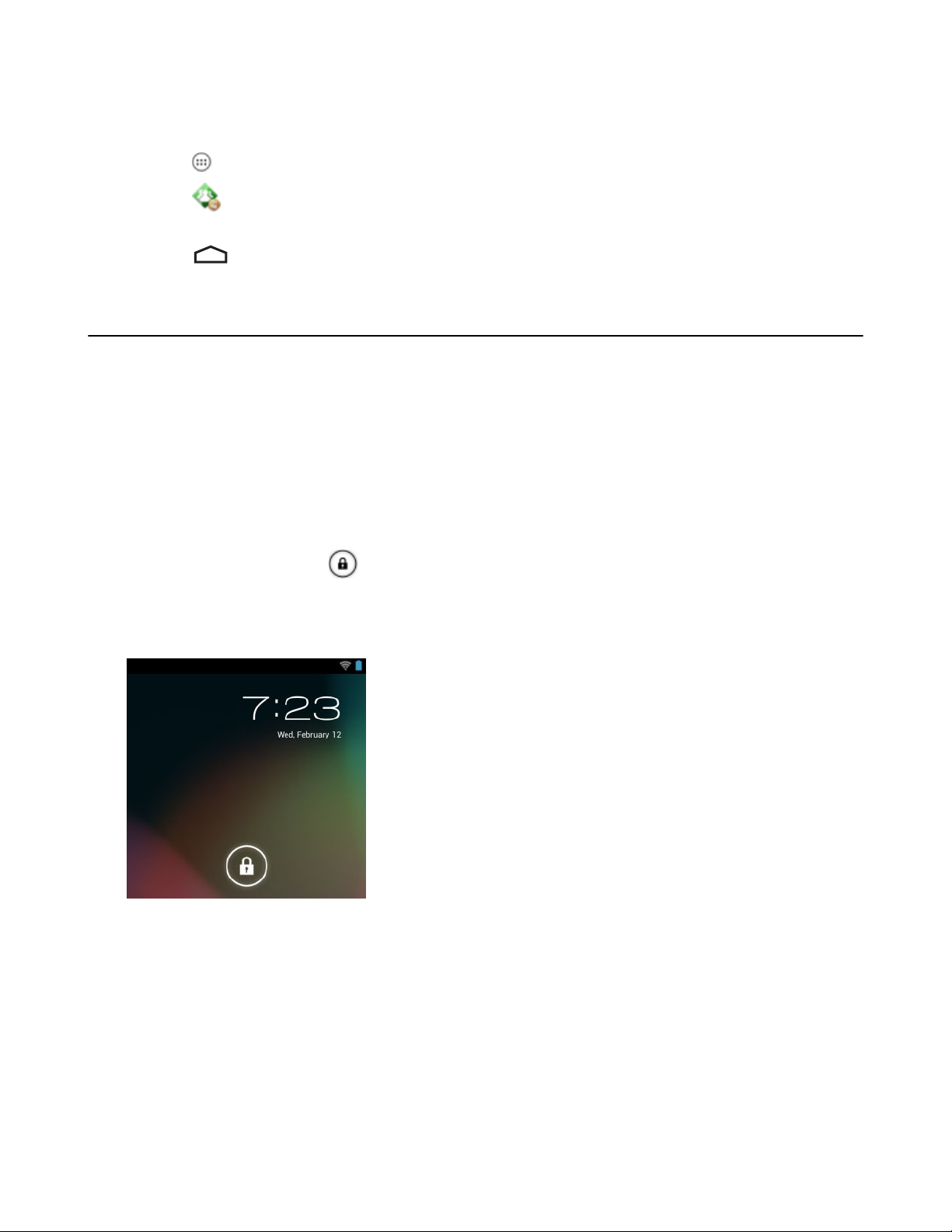
62 | Using the MC32N0 with Android
™
Disabling PTT Express Voice Client Communication
Procedure:
1
Touch .
2
Touch
3 Slide the Enable/Diable Switch to the OFF position. The button changes to OFF.
4
Touch .
.
Un-Locking the Screen
Use the Lock screen to protect access to data on the MC32N0. Some email account require locking the screen. Refer
to the MC32N0 Integrator Guide for information on setting up the locking feature. The Locking feature functions
differently in Single User mode or Multiple User mode.
Single User Mode
When locked, a PIN or password is required to unlock the device. Press the Power button to lock the screen. The
device also locks after a pre-defined time-out.
Press and release the Power button to wake the device.
The Lock screen displays. Slide up to unlock the screen.
If the PIN or Password screen unlock feature is enabled, enter the PIN or password after unlocking the screen.
Figure 55: Lock Screen
April 2015 | MN000886A01-B
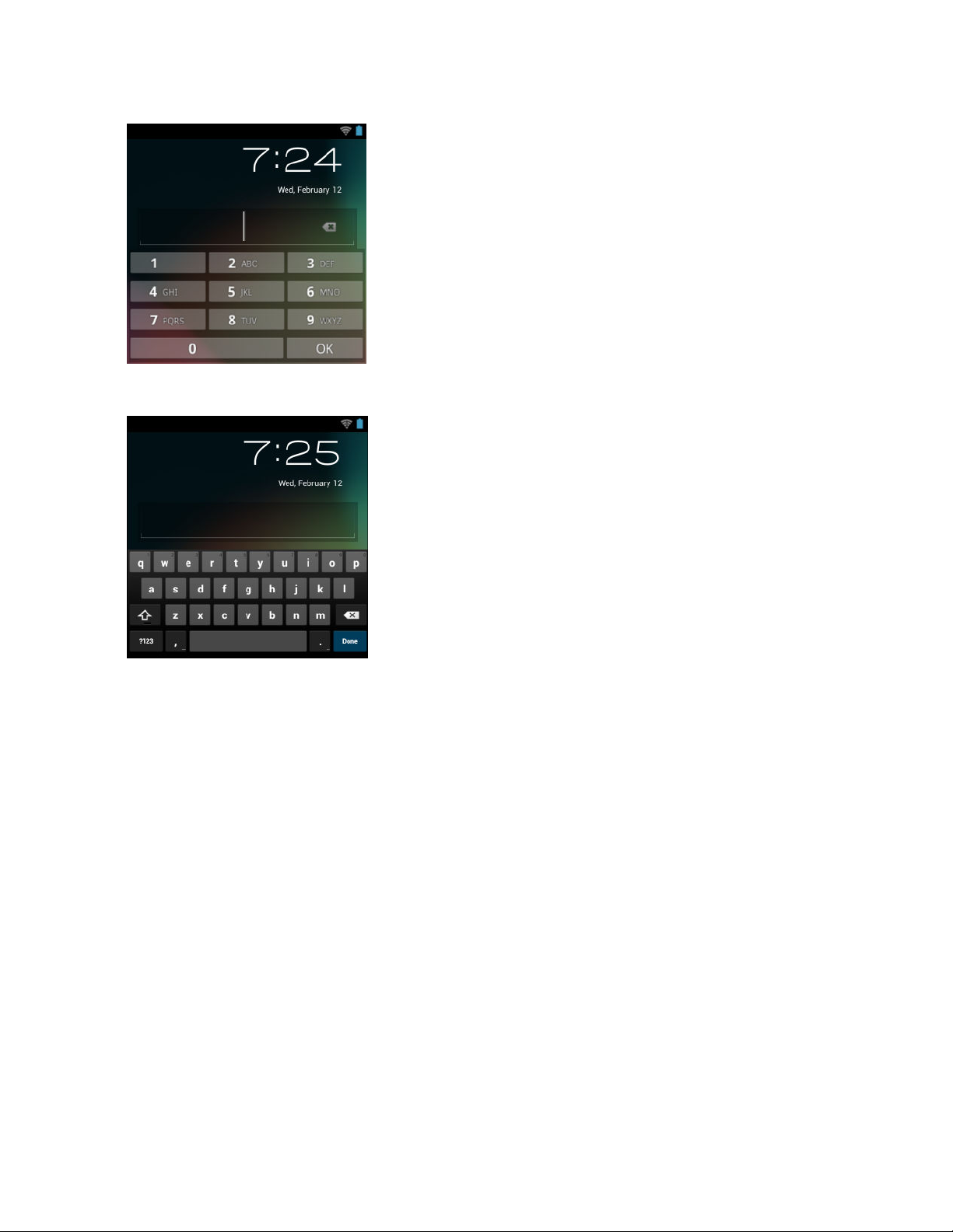
Figure 56: PIN Screen
Figure 57: Password Screen
Using the MC32N0 with Android™ | 63
MultiUser Mode
With MultiUser login, multiple users can log on to the device with each user having access to various applications
and features. When enabled, the Login screen appears after powering on, resetting or after the device wakes from
suspend mode.
MultiUser Login
Procedure:
1 In the Login text field, enter the username.
MN000886A01-B | April 2015
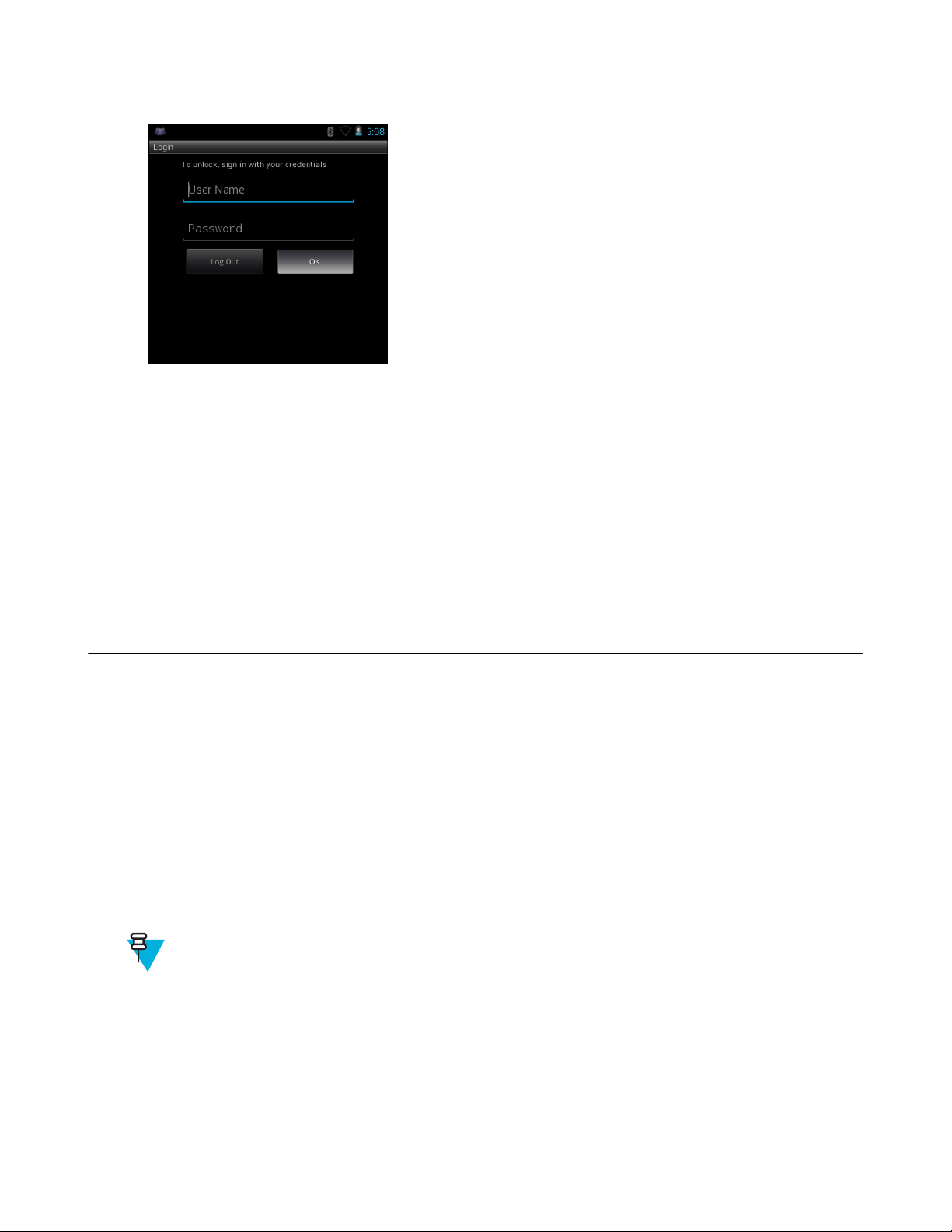
64 | Using the MC32N0 with Android
Figure 58: Multiple User Log In Screen
2 In the Password text field, enter the password.
3 Touch OK. After a resume from suspend, the user must enter the password.
™
MultiUser Logout
Procedure:
1 Drag the Status Bar down from the top of the screen.
2 Touch MultiUser is active.
3 Touch Logout.
4 The Login screen appears.
Resetting the Android Device
There are two reset functions, soft reset and hard reset.
Performing a Soft Reset
Perform a soft reset if applications stop responding.
Procedure:
1 Press and hold the Power button until the menu appears.
2 Touch Reset.
3 The device reboots.
Performing a Hard Reset
Note: All un-saved data is lost after performing a Hard Reset.
Perform a Hard Reset if the device stops responding. To perform a Hard Reset:
Procedure:
1 Simultaneously press the Power button, 1 and 9 keys.
2 The device reboots.
April 2015 | MN000886A01-B

Using the MC32N0 with Android™ | 65
Suspend Mode
The MC32N0 goes into suspend mode when the user presses the Power button or after a period of inactivity (set in
the Display settings window).
To wake the MC32N0 from Suspend mode, press the Power button.
The Lock screen displays. Slide
62.
Note:
If the user enters the PIN, password or pattern incorrectly five times, they must wait 30 seconds before
trying again.
If the user forgets the PIN, password or pattern contact the system administrator.
Figure 59: Lock Screen
to the right toward to unlock the screen. See Un-Locking the Screen on page
Setting the Date and Time
The date and time is automatically synchronized using an NITZ server when the MC32N0 is connected to a wireless
network. The user is only required to set the time zone or set the date and time when not connected to a wireless
network.
Procedure:
1
Touch .
2
Touch Date & time.
3 Touch Automatic date & time to disable automatic date and time synchronization.
4 Touch Automatic time zone to disable automatic time zone synchronization.
5 Touch Set date.
6 Move the sliders up and down to select the month, date and year.
7 Touch Done.
8 Touch Set time.
9 Move the sliders up and down to select the hour, minutes and part of the day.
10 Touch Done.
11 Touch Select time zone.
MN000886A01-B | April 2015
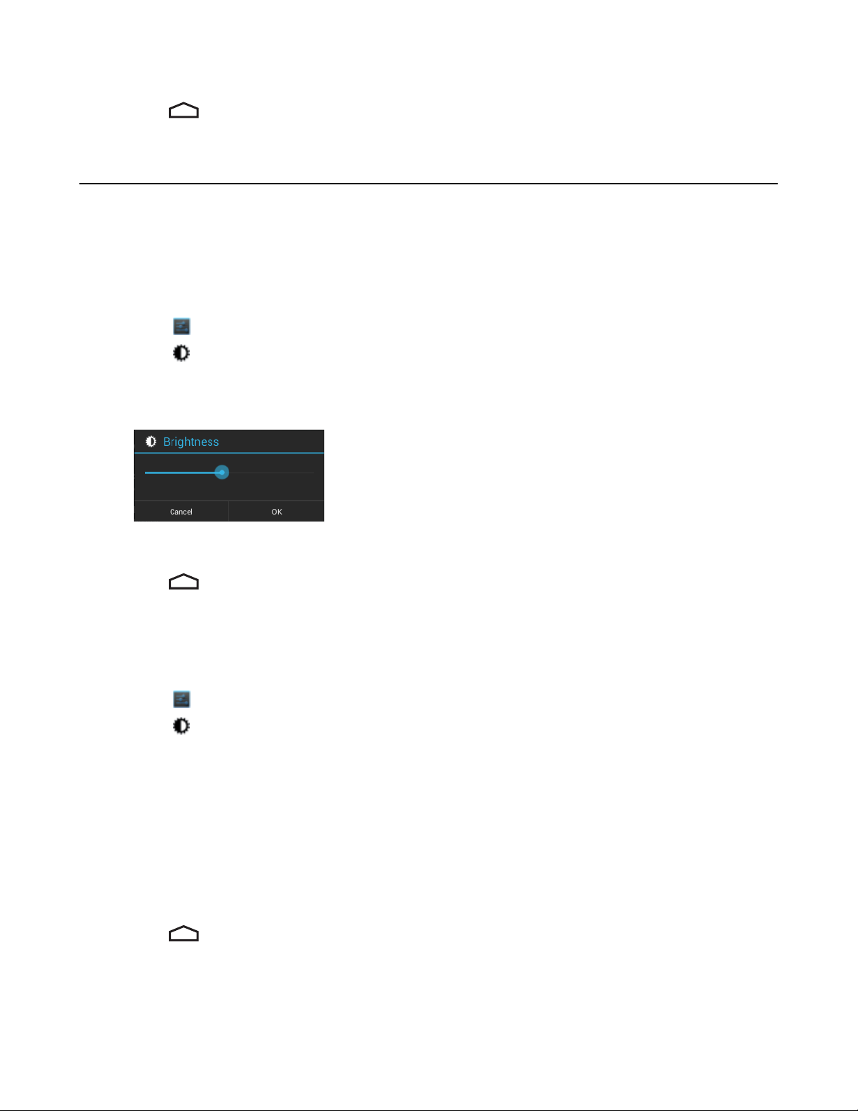
66 | Using the MC32N0 with Android
12 Select the current time zone from the list.
13
Press .
™
Display Setting
Use Display settings to change the screen brightness, change the background image, set sleep time and change font
size.
Setting the Screen Brightness
Procedure:
1
Touch .
2
Touch Display.
3 Touch Brightness.
Figure 60: Brightness Dialog Box
4 Use the slider to set a brightness level.
5 Touch OK.
6
Press .
Changing the Screen Timeout Setting
To set the MC32N0 to turn off after a short period of non-use:
Procedure:
1
Touch .
2
Touch Display
3 Touch Sleep
4 Select a value from the Sleep window. Options:
• 15 seconds
• 30 seconds
• 1 minute (default)
• 2 minutes
• 5 minutes
• 10 minutes
• 30 minutes
5
Press .
April 2015 | MN000886A01-B

Using the MC32N0 with Android™ | 67
General Sounds Setting
Use the Sounds settings to configure media and alarm volumes. Touch > > Sounds.
Figure 61: Sounds Screen
• Volumes — Use to change the volume of media, notifications and alarms.
Figure 62: Volumes Dialog Box
• System
- Default notification - Touch to select a sound to play for all system notifications.
- Touch sounds - Check to play a sound when making screen selections.
- Screen lock sounds - Check to play a sound when locking and unlocking the screen.
Wireless Local Area Networks
Wireless local area networks (WLANs) allow the MC32N0 to communicate wirelessly inside a building. Before using
the MC32N0 on a WLAN, the facility must be set up with the required hardware to run the WLAN (sometimes
known as infrastructure). The infrastructure and the MC32N0 must both be properly configured to enable this
communication.
Refer to the documentation provided with the infrastructure (access points (APs), access ports, switches, Radius
servers, etc.) for instructions on how to set up the infrastructure.
Once the infrastructure is set up to enforce the chosen WLAN security scheme, use the Wireless & networks settings
configure the MC32N0 to match the security scheme.
MN000886A01-B | April 2015

68 | Using the MC32N0 with Android
The MC32N0 supports the following WLAN security options:
• Open
• Wireless Equivalent Privacy (WEP)
• Wi-Fi Protected Access (WPA)/WPA2 Personal (PSK)
Extensible Authentication Protocol (EAP)
•
- LEAP
- FAST - with Microsoft Challenge-Handshake Authentication Protocol version 2 (MSCHAPv2) and Generic
Token Card (GTC) authentication.
- Protected Extensible Authentication Protocol (PEAP) - with MSCHAPV2 and GTC authentication.
- Transport Layer Security (TLS)
- TTLS - with Password Authentication Protocol (PAP), MSCHAP and MSCHAPv2 authentication.
The Status bar displays icons that indicate Wi-Fi network availability and Wi-Fi status. See Status Bar on page 40 for
more information.
Note: Turn off Wi-Fi when not using it, to extend the life of the battery.
™
Scan and Connect to a Wi-Fi Network
Procedure:
1
Touch .
2
Touch
Figure 63: Settings Screen
3 Slide the Wi-Fi switch to the ON position.
4
Touch Wi-Fi. The MC32N0 searches for WLANs in the area and lists them.
.
April 2015 | MN000886A01-B

Using the MC32N0 with Android™ | 69
Figure 64: Wi-Fi Screen
5 Scroll through the list and select the desired WLAN network.
6 For open networks, touch profile once or press and hold and then select Connect to network or for secure
networks enter the required password or other credentials then touch Connect. See the system administrator for
more information.
The MC32N0 obtains a network address and other required information from the network using the dynamic host
configuration protocol (DHCP) protocol. To configure the MC32N0 with a fixed internet protocol (IP) address,
See Configuring the Device to Use a Static IP Address on page 72.
7 In the Wi-Fi setting field, Connected appears indicating that the MC32N0 is connected to the WLAN.
Configuring a Wi-Fi Network
To set up a Wi-Fi network:
Procedure:
1
Touch .
2
Touch .
3
Touch Wi-Fi.
4 Slide the switch to the ON position.
5 The device searches for WLANs in the area and lists them on the screen.
6 Scroll through the list and select the desired WLAN network.
7 Touch the desired network. If the network security is Open, the device automatically connects to the network. For
all other network security a dialog box appears.
MN000886A01-B | April 2015

70 | Using the MC32N0 with Android
Figure 65: WLAN Network Security Dialog Box
™
8 If the network security is WEP or WPA/WPS2 PSK, enter the required password and then touch Connect.
9 If the network security is 802.1x EAP:
• Touch the EAP method drop-down list and select PEAP, TLS
• Touch the Phase 2 authentication drop-down list and select an authentication method.
• If required, touch CA certificate and select a Certification Authority (CA) certificate. Note: Certificates are
installed using the Security settings.
• If required, touch User certificate and select a user certificate. Note: User certificates are installed using the
Location & security settings.
• If required, in the Identity text box, enter the username credentials.
• If desired, in the Anonymous identity text box, enter an anonymous identity username.
• If required, in the Password text box, enter the password for then given identity.
10
Touch Connect.
11
Press
Note: By default, the network Proxy is set to None and the IP settings is set to DHCP. See Configuring
for a Proxy Server on page 71 for setting connection to a proxy server and see Configuring the Device
to Use a Static IP Address on page 72
.
for setting the device to use a static IP address.
, TTLS or PWD.
Manually Adding a Wi-Fi Network
Manually add a Wi-Fi network if the network does not broadcast its name (SSID) or to add a Wi-Fi network when out
of range.
Procedure:
1
Touch .
2
Touch Wi-Fi.
3 Slide the Wi-Fi switch to the On position.
April 2015 | MN000886A01-B

Using the MC32N0 with Android™ | 71
4 In the Network SSID text box, enter the name of the Wi-Fi network.
5 In the Security drop-down list, select the type of security. Options:
• None
• WEP
• WPA/WPA2 PSK
• 802.1x EAP.
6 If the network security is None, touch Save.
7 If the network security is WEP or WPA/WPA2 PSK, enter the required password and then touch Save.
8 If the network security is 802.1x EAP:
• Touch the EAP method drop-down list and select PEAP,
• Touch the Phase 2 authentication drop-down list and select an authentication method.
• If required, touch CA certificate and select a Certification Authority (CA) certificate. Note: Certificates are
installed using the Security settings.
• If required, touch User certificate and select a user certificate. Note: User certificates are installed using the
Security settings.
• If required, in the Identity text box, enter the username credentials.
• If desired, in the Anonymous identity text box, enter an anonymous identity username.
• If required, in the Password text box, enter the password for then given identity.
9
Touch Connect.
10
Press
Note: By default, the network Proxy is set to None and the IP settings is set to DHCP. See Configuring
for a Proxy Server on page 71 for setting connection to a proxy server and see Configuring the Device
to Use a Static IP Address on page 72
.
for setting the device to use a static IP address.
TLS or TTLS.
Configuring for a Proxy Server
A proxy server is a server that acts as an intermediary for requests from clients seeking resources from other servers.
A client connects to the proxy server, requesting some service, such as a file, connection, web page, or other resource,
available from a different server. The proxy server evaluates the request according to its filtering rules. For example,
it may filter traffic by IP address or protocol. If the request is validated by the filter, the proxy provides the resource
by connecting to the relevant server and requesting the service on behalf of the client.
It is important for enterprise customers to be able to set up secure computing environments within their companies,
and proxy configuration is an essential part of doing that. Proxy configuration acts as a security barrier ensuring that
the proxy server monitors all traffic between the Internet and the intranet. This is normally an integral part of security
enforcement in corporate firewalls within intranets.
Procedure:
1 In the network dialog box, touch a network.
2 Touch Show advanced options checkbox.
3 Touch Proxy settings and select Manual.
MN000886A01-B | April 2015

72 | Using the MC32N0 with Android
Figure 66: Proxy Settings
4 In the Proxy hostname text box, enter the address of the proxy server.
5 In the Proxy port text box, enter the port number for the proxy server.
Note: When entering proxy addresses the Bypass proxy for field, do not use spaces or carriage returns
between addresses.
™
6 In the Bypass proxy for text box, enter addresses for web sites that do not require to go through the proxy server.
Use the separator “|” between addresses.
7 Touch Connect.
8
Press .
Configuring the Device to Use a Static IP Address
By default, the device is configured to use Dynamic Host Configuration Protocol (DHCP) to assign an Internet
protocol (IP) address when connecting to a wireless network. To configure the device to connect to a network using a
static IP address:
Procedure:
1 In the network dialog box, touch a network.
2 Touch Show advanced options checkbox.
3 Touch IP settings and select Static.
Figure 67: Static IP Settings
4 In the IP address text box, enter an IP address for the device.
5 If required, in the Gateway text box, enter a gateway address for the device.
April 2015 | MN000886A01-B

Using the MC32N0 with Android™ | 73
6 If required, in the Network prefix length text box, enter a the prefix length.
7 If required, in the DNS 1 text box, enter a Domain Name System (DNS) address.
8 If required, in the DNS 2 text box, enter a DNS address.
9 Touch Connect.
10
Press .
Advanced Wi-Fi Settings
Note: Advanced Wi-Fi settings are for the device not for a specific wireless network.
Use the Advanced settings to configure additional Wi-Fi settings. From the Wi-Fi screen, touch > Advanced to
view the advanced settings.
Use the Advanced settings to configure additional Wi-Fi settings. Press > Advanced to view the advanced
settings.
• General
- Network notification - When enabled, notifies the user when an open network is available.
- Keep Wi-Fi on during sleep - Opens a menu to set whether and when the Wi-Fi radio turns off.
+ Always On - The radio stays on when the device enters suspend mode.
+ Only when plugged in - The radio stays on while the device is connected to external power.
+ Never On - The radio turns off when the device enters suspend mode (default).
- MAC address - Displays the Media Access Control (MAC) address of the device when connecting to Wi-Fi
networks.
• Regulatory
- Country selection - Displays the acquired country code if 802.11d is enabled else it displays the currently
selected country code.
- Region code - Displays the current region code.
• Band and Channel Selection
- Wi-Fi frequency band - Use to select the frequency band. Options: Auto (default), 5 GHz only or 2.4 GHz
only.
- Available channels (2.4 GHz) - Use to select specific channels. Touch to display the Available channels
menu. Select specific channels. Touch OK.
- Available channels (5 GHz) - Use to select specific channels. Touch to display the Available channels menu.
Select specific channels. Touch OK.
• Logging
- Advanced Logging - Provides support for continuous capture of system logs to a file to help in debugging and
resolution of Wi-Fi related issues. Disabled by default. In the Advanced Logging dialog box, select Enable
Logging. If desired, change the log directory location. When enabled, the following log are captured:
Note:
The MC32N0 must have a microSD card installed.
All log files are saved in /storage/sdcard0/fusionlogs on the MC32N0.
Fusion will ask the user whether he wants to clear out previous logs before starting logging.
tcpdump capture file and fusion-sysinfo.log will only be generated when advanced logging
is stopped.
+ Android logcat output with time stamps and the kernel messages in the file: fusion-wlan.log.
MN000886A01-B | April 2015

74 | Using the MC32N0 with Android
+ tcpdump intermediate capture of packets between network stack and driver in the file: fusion-
pktcap.pcap
+ Fusion versions, Wi-Fi state machine logs and other framework information in the file: fusion-
sysinfo.log.
• About
- Version - Displays the current Fusion information.
™
Remove a Wi-Fi Network
To remove a remembered or connected network:
Procedure:
1
Touch
2
Touch .
3
Touch Wi-Fi.
4 In the Wi-Fi networks list, touch and hold the name of the network.
5 In the menu, touch Forget network.
6
Press .
.
Bluetooth
Bluetooth-equipped devices can communicate without wires, using frequency-hopping spread spectrum (FHSS) radio
frequency (RF) to transmit and receive data in the 2.4 GHz Industry Scientific and Medical (ISM) band (802.15.1).
Bluetooth wireless technology is specifically designed for short-range (10 meters (32.8 feet) ) communication and
low power consumption.
Devices with Bluetooth capabilities can exchange information (e.g., files, appointments, and tasks) with other
Bluetooth enabled devices such as printers, access points, and other mobile devices.
Adaptive Frequency Hopping
Adaptive Frequency Hopping (AFH) is a method of avoiding fixed frequency interferers, and can be used with
Bluetooth voice. All devices in the piconet (Bluetooth network) must be AFH-capable in order for AFH to work.
There is no AFH when connecting and discovering devices. Avoid making Bluetooth connections and discoveries
during critical 802.11b communications. AFH for Bluetooth consists of four main sections:
• Channel Classification - A method of detecting an interference on a channel-by-channel basis, or pre-defined
channel mask.
• Link Management - Coordinates and distributes the AFH information to the rest of the Bluetooth network.
• Hop Sequence Modification - Avoids interference by selectively reducing the number of hopping channels.
• Channel Maintenance - A method for periodically re-evaluating the channels.
When AFH is enabled, the Bluetooth radio “hops around” (instead of through) the 802.11b high-rate channels. AFH
coexistence allows Zebra devices to operate in any infrastructure.
The Bluetooth radio in this device operates as a Class 2 device power class. The maximum output power is 2.5 mW
and the expected range is 10 meters (32.8 ft.). A definition of ranges based on power class is difficult to obtain due to
power and device differences, and whether one measures open space or closed office space.
Note: It is not recommended to perform Bluetooth wireless technology inquiry when high rate 802.11b
operation is required.
April 2015 | MN000886A01-B

Using the MC32N0 with Android™ | 75
Security
The current Bluetooth specification defines security at the link level. Application-level security is not specified. This
allows application developers to define security mechanisms tailored to their specific need. Link-level security occurs
between devices, not users, while application-level security can be implemented on a per-user basis. The Bluetooth
specification defines security algorithms and procedures required to authenticate devices, and if needed, encrypt the
data flowing on the link between the devices. Device authentication is a mandatory feature of Bluetooth while link
encryption is optional.
Pairing of Bluetooth devices is accomplished by creating an initialization key used to authenticate the devices and
create a link key for them. Entering a common personal identification number (PIN) in the devices being paired
generates the initialization key. The PIN is never sent over the air. By default, the Bluetooth stack responds with no
key when a key is requested (it is up to user to respond to the key request event). Authentication of Bluetooth devices
is based-upon a challenge-response transaction. Bluetooth allows for a PIN or passkey used to create other 128-bit
keys used for security and encryption. The encryption key is derived from the link key used to authenticate the pairing
devices. Also worthy of note is the limited range and fast frequency hopping of the Bluetooth radios that makes longdistance eavesdropping difficult.
Recommendations are:
• Perform pairing in a secure environment
• Keep PIN codes private and do not store the PIN codes in the device
•
Implement application-level security.
Bluetooth Profiles
The MC32N0 with Android supports the following Bluetooth services:
• Generic Access Profile (GAP) - Use for device discovery and authentication.
• Service Discovery Access Protocol (SDP) - Handles the search for known and specific services as well as general
services.
• Serial Port Profile (SPP) - Sets up a virtual serial port and connects two Bluetooth enabled devices. For example,
connecting the MC32N0 to a printer.
• Human Interface Device Profile (HID) - Allows Bluetooth keyboards, pointing devices, gaming devices and
remote monitoring devices to connect to the MC32N0.
• Dial-up Networking (DUN) - Allows the MC32N0 to access the Internet and other dial-up services using a
Bluetooth enabled mobile phone.
• Personal Area Network (PAN) - Allow the use of Bluetooth Network Encapsulation Protocol on Layer 3 protocols
for transport over a Bluetooth link.
• General Object Exchange Profile (GOEP) - Provides a basis for other data profiles. Based on OBEX and
sometimes referred to as such.
Bluetooth Power States
The Bluetooth radio is off by default.
• Suspend - When the MC32N0 goes into suspend mode, the Bluetooth radio stays on.
• Airplane Mode - When the MC32N0 is placed in Airplane Mode, the Bluetooth radio turns off. When Airplane
mode is disabled, the Bluetooth radio returns to the prior state. When in Airplane Mode, the Bluetooth radio can
be turned back on if desired.
Bluetooth Radio Power – Android
Turn off the Bluetooth radio to save power or if entering an area with radio restrictions (e.g., an airplane). When the
radio is off, other Bluetooth devices cannot see or connect to the device. Turn on the Bluetooth radio to exchange
information with other Bluetooth devices (within range). Communicate only with Bluetooth radios in close proximity.
MN000886A01-B | April 2015

76 | Using the MC32N0 with Android
Note: To achieve the best battery life turn off radios when not in use.
™
Enabling Bluetooth
Procedure:
1
Touch .
2
Touch .
3
Slide the Bluetooth switch to the ON position. also appears in the Status bar.
4
Press .
Disabling Bluetooth
Procedure:
1
Touch .
2
Touch .
3 Slide the Bluetooth switch to the OFF position.
4
Press .
Discovering Bluetooth Device(s)
The MC32N0 can receive information from discovered devices without pairing. However, once paired, the MC32N0
and a paired device exchange information automatically when the Bluetooth radio is on. To find Bluetooth devices in
the area:
Procedure:
1 Ensure that Bluetooth is enabled on both devices.
2 Ensure that the Bluetooth device to discover is in discoverable mode.
3 Ensure that the two devices are within 10 meters (32.8 feet) of one another.
4
Touch .
5
Touch .
6
Touch Bluetooth.
7 Touch SCAN FOR DEVICES. The MC32N0 begins searching for discoverable Bluetooth devices in the area and
displays them under AVAILABLE DEVICES.
8 Scroll through the list and select a device. The Bluetooth pairing request dialog box appears.
April 2015 | MN000886A01-B
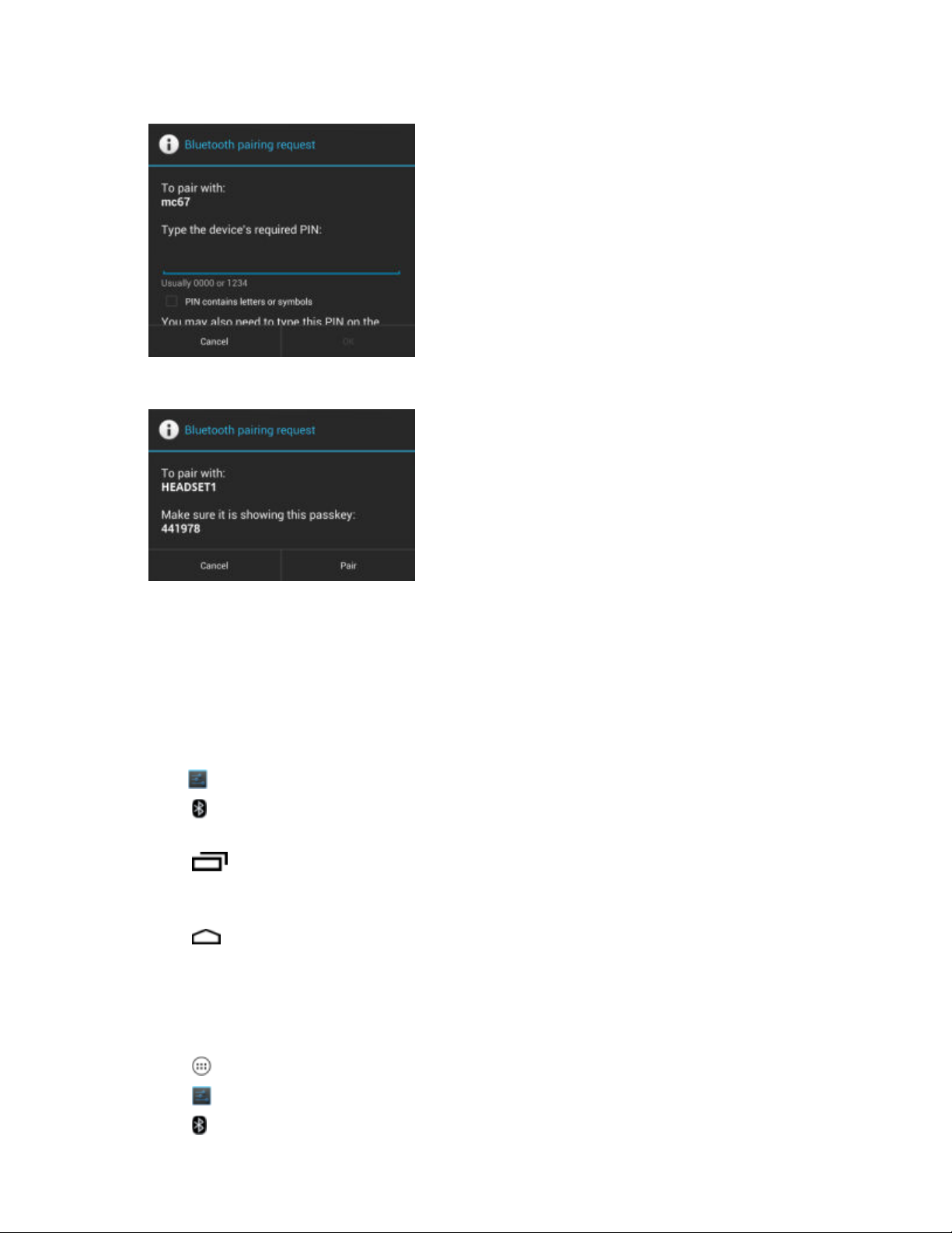
Figure 68: Bluetooth Pairing - Enter PIN
Figure 69: Bluetooth Pairing - Smart Pairing
Using the MC32N0 with Android™ | 77
9 Enter a PIN in the text box and touch OK. Enter the same PIN on the other device.
10 For Simple Pairing, touch Pair on both devices.
11 The Bluetooth device is added to the Bluetooth devices list and a trusted (“paired”) connection is established.
Changing the Bluetooth Name
By default, the MC32N0 has a generic Bluetooth name that is visible to other devices when connected.
Procedure:
1
Touch .
2
Touch Bluetooth.
3 If Bluetooth is not on, slide the switch to the ON position.
4
Touch .
5 Touch Rename device.
6 In the Rename device dialog box, enter a name and touch Rename.
7
Touch .
Connecting to a Bluetooth Device
Once paired, connect to a Bluetooth device.
Procedure:
1
Touch .
2
Touch .
3
Touch Bluetooth.
MN000886A01-B | April 2015

78 | Using the MC32N0 with Android
4 If Bluetooth is not on, slide the switch to the ON position.
5 In the PAIRED DEVICES list, touch and hold on a unconnected Bluetooth device until a menu appears.
6 Touch Connect. When connected, the device is displayed as connected in the list.
™
Selecting Profiles on the Bluetooth Device
Some Bluetooth devices have multiple profiles. To select a profile:
Procedure:
1
Touch .
2
Touch .
3
Touch Bluetooth.
4
In the PAIRED DEVICES list, touch next to the device name.
5 Under PROFILES, check or uncheck a profile to allow the device to use that profile.
6
Press .
Unpairing a Bluetooth Device
To unpair a Bluetooth device and erase all pairing information:
Procedure:
1
Touch .
2
Touch .
3
Touch Bluetooth.
4
In the PAIRED DEVICES list, touch
5 Touch Unpair.
6
Press .
next to the device name.
April 2015 | MN000886A01-B
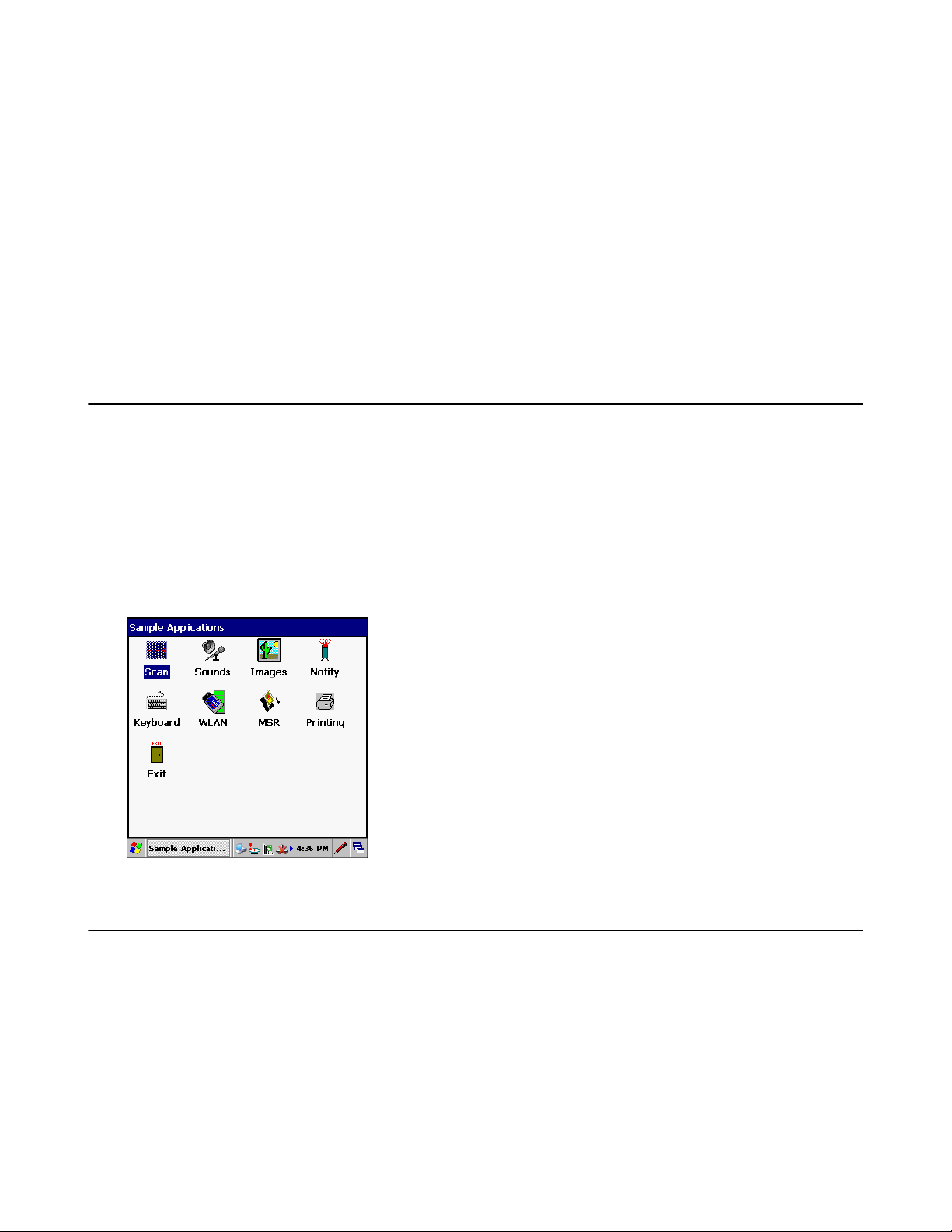
79 | Using the MC32N0 with Windows CE
Chapter
3
Using the MC32N0 with Windows CE
This chapter describes the screens, status and notification icons, and controls on the MC32N0, and provides basic
instructions for using the MC32N0.
Sample Applications Window
The MC32N0 with Windows CE contains a set of sample applications that can be installed. By default an installation
icon is on the Desktop. Double-tap the icon to install the sample applications. When installed, the Sample
Applications window appears on the screen whenever the MC32N0 re-boots. Refer to the MC32N0 Integrator Guide
for installation and configuration.
The Sample Applications window links to sample applications. The sample applications are intended to be used by
application developers as application development examples. These applications were not developed to support end
users. Refer to the Application Guide for Zebra Enterprise Mobility Devices for the sample applications.
Figure 70: Sample Applications Window
Desktop
The desktop screen displays when the MC32N0 turns on. Depending upon the configuration, the Home screen might
appear different. Contact your system administrator for more information.
MN000886A01-B | April 2015

80 | Using the MC32N0 with Windows CE
Figure 71: Desktop
Taskbar
The Taskbar at the bottom of the window displays the active programs, current time, battery status and
communication status.
Figure 72: Notification and Status Icons
Table 14: Windows CE Taskbar
Item Description
1 Start Button
2 Open Programs
3 Status Icons
4 Input Panel Button
5 Desktop Button
Status Icons
Table 15: Status Icons
Icon Description
Clock: Indicates the current time.
Battery: This icon indicates that the main battery is charging or that the terminal is operating on
AC power. Double tapping on this icon opens the Power Properties window.
AC Plug: Indicates that the battery is fully charged and the MC32N0 is running on external power.
April 2015 | MN000886A01-B
Table continued…
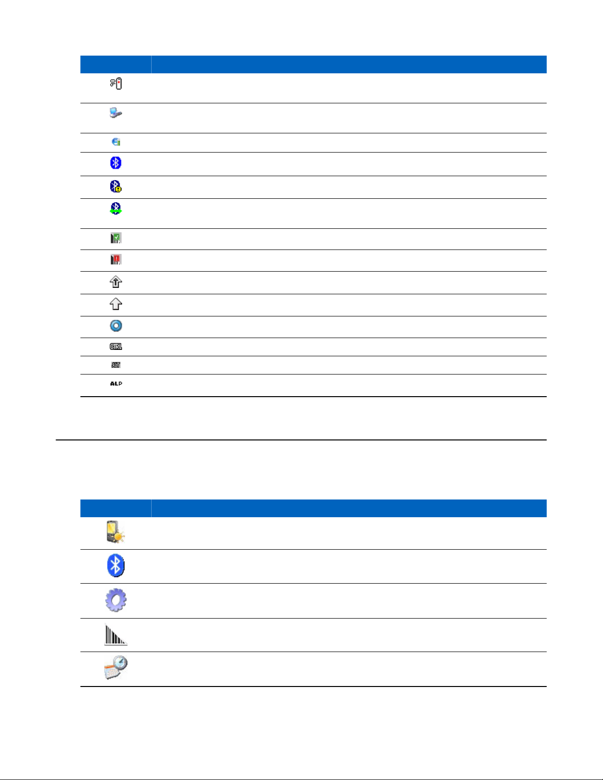
Icon Description
Battery: This icon indicates that the battery is fully charged (100% charged). The battery status
icons provide the battery status in 10% increments from 10% to 100%.
Serial Connection: It is displayed when the terminal is connected to a host computer with a serial
cable.
Wireless Connection Status: Indicates WLAN signal strength.
Bluetooth Enabled: Indicates that the Bluetooth radio is on.
Bluetooth Disabled: Indicates that the Bluetooth radio is off (BTExplorer only).
Bluetooth Communication: Indicates that the MC32N0 is communicating with another Bluetooth
device (BTExplorer only).
DataWedge Running: Indicates that the DataWedge application is running.
DataWedge Idle: Indicates that the DataWedge application is idle.
Shift: Indicates that the SHIFT key function is selected.
Using the MC32N0 with Windows CE | 81
Shift-Lock: Indicates that the SHIFT key is selected and locked.
FUNC: Indicates that the FUNC button function is selected.
CTRL: Indicates that the CTRL button function is selected.
ALT: Indicates that the ALT character selection is selected.
ALPHA: Indicates that the MC32N0 is in ALPHA button mode is selected.
Control Panel
The table below lists the applications in the Control Panel.
Table 16: Applications in the Programs Menu
Icon Description
Backlight: Adjust the backlight brightness and power settings.
Bluetooth Device Properties: Launch the StoneStreet One application when enabled..
Certificates: See information about certificates installed on the MC32N0.
DataWedge: Sample scanning application. Icon appears after installation.
Date/Time: Change date, time and time zone information.
MN000886A01-B | April 2015
Table continued…

82 | Using the MC32N0 with Windows CE
Icon Description
Dialing: Set dialing properties for modem communication and change telephony settings.
Display: Change desktop background, appearance, backlight and brightness.
Error Reporting: Choose whether to MC32N0 collects software operation information to use if a
serious error occurs.
Input Panel: Switch input methods and set input options.
Internet Options: Control how the MC32N0 connects to the internet.
IST Settings: Set the appropriate settings for configuring the MC32N0’s Interactive Sensor Tech-
nology.
Keyboard: Change keyboard repeat delay and rate.
MotoBTUI: Opens the MotoBTUI application when Microsoft Bluetooth stack is enabled.
Mouse: Adjust double-click sensitivity for both the speed and timing.
Network and Dial-up Connections: Connect to other computers, networks and the Internet using
a modem.
Owner: Change owner’s personal profiles.
Password: Set a password for the MC32N0.
PC Connection: Change settings for connectivity of a host computer.
Power: View and control MC32N0 power settings.
Regional Settings: Change how numbers, currencies, dates and times appear.
Remove Programs: Remove programs installed on the MC32N0.
Stylus: Calibrate the touch screen and adjust double-tap timing.
System: View system information and change memory settings.
System Info: View information on the MC32N0’s system components.
April 2015 | MN000886A01-B
Table continued…

Using the MC32N0 with Windows CE | 83
Icon Description
USBConfig: Configure the MC32N0 USB port.
Volume & Sounds: Select the type of actions for which to hear sounds and customize notifica-
tions for different events.
Start Menu
To open the Start menu, tap at the bottom left corner of the screen. The table below lists the default applications
available in the Programs menu.
Table 17: Applications in the Programs Menu
Icon Description
Fusion Folder: Open the Wireless Companion folder.
Debug Folder: Open the Debug folder that contains eMscript installation file. Once installed, con-
tains Start eMscript and Stop eMscript applications.
BatteryHealthManagementApp: Installs the BatteryHealthManagementApp application on the
MC32N0. Note: Perform a cold boot after installation.
BattSwap: Use to properly shutdown the MC32N0 during battery replacement.
BTScanner CtlPanel: Set com port to use with a Bluetooth scanner.
Command Prompt: Opens a DOS command prompt window.
CtlPanel: View and change MC32N0 settings such as: Scanner Parameters, Display Settings, Au-
dio Settings, Printer Settings, Date and Time Settings, Touch Screen Settings, etc.
DataWedgeDemo - Sample scanning application. Icon appears after installation.
Internet Explorer: Browse Web and WAP sites as well as download new programs and files from
the Internet.
Media Player: Play back audio files.
Microsoft WordPad: Create documents.
Mobi Control Agent: Opens the SOTI MobiScan Agent application after installation.
MotoBTUI: Pairs bar code with the MC32N0 via Bluetooth and uses the RS507 Hands-free Im-
ager to capture the bar code data.
Table continued…
MN000886A01-B | April 2015

84 | Using the MC32N0 with Windows CE
Icon Description
MSP Agent: Interacts with MSP agents to collect monitoring and asset information to enable the
configuration, provisioning, monitoring and troubleshooting of the MC32N0. Refer to the
MC32N0 Integrator Guide for more information.
PTT Express Configuration - Initially installs the PTT Express Configuration application on
the MC32N0. Opens the PTT Express Configuration application after installation.
Rapid Deployment Client: Facilitates software downloads from a Mobility Services Platform
Console FTP server to the MC32N0. Refer to the Mobility Services Platform documentation for
more information.
Remote Desktop Connection: Log onto Windows NT server type computers and use all of the
programs that are available on that computer from the MC32N0.
Samples - Opens the Sample Applications window, when installed.
SOTI MobiScan Agent: Installs the Mobi Control Agent application on the MC32N0.
TelentCE: Opens the Wavelink Telnet client.
WarmBoot: Warm boots the MC32N0.
Windows Explorer: Organize and manage files on your device.
DataWedge Demo
Use DataWedge Demo to demonstrate data capture functionality.
Figure 73: DataWedge Demo Window
Press the scanner button to capture the bar code data. The bar code contents appears in the text box.
April 2015 | MN000886A01-B

1
2
Using the MC32N0 with Windows CE | 85
PTT Express Configuration
Note:
PTT Express Configuration creates Push-To-Talk (PTT) communication capability between disparate
enterprise devices. Leveraging existing Wireless Local Area Network (WLAN) infrastructure, PTT Express
delivers simple PTT communication without the need of a voice communication server.
• Group Call: Press and hold the Group Call button (green button) to start communicating with other voice client
users.
• Private Response: Press and hold the Private Response button (red button) to respond to the originator of the last
broadcast or to make a Private Response.
Figure 74: PTT Button Assignment
1 Green Button – Group Call button
2 Red Button – Private Response button
PTT Audible Indicators
The following tones provide helpful cues when using the voice client.
• Talk Tone: Double chirp. Plays when the Group Call or Private Response button is depressed. This is a prompt
for the user to start talking.
• Access Tone: Single beep. Plays when another user just finished a broadcast or response. The user is now able to
initiate a Group Call or Private Response.
• Busy Tone: Continuous tone. Plays when the Group Call or Private Response button is depressed and another user
is already communicating on the same talkgroup. Plays after the maximum allowed talk time is reached (60
seconds).
• Network Tone:
- Three increasing pitch beeps. Plays when PTT Express has acquired the WLAN connection and the service is
enabled.
- Three decreasing pitch beeps. Plays when PTT Express has lost the WLAN connection or the service is
disabled.
MN000886A01-B | April 2015

86 | Using the MC32N0 with Windows CE
Figure 75: PTT Express Window
Select the Voice Client Enabled checkbox to enable PTT Express.
In the drop-down menu, select a talkgroup.
Creating a Group Call
Procedure:
1 Press and hold the Group Call button and listen for the talk tone to play.
If a busy tone is heard, release the button and wait a moment before making another attempt. Ensure that PTT
Express and the WLAN are enabled.
2 Start talking after the talk tone is heard.
Note: If the user holds the button for more than 60 seconds (default), the call is dropped allowing others
to make Group calls. The user should release the button when finished talking to allow others to make
calls.
3 Release the button when finished talking.
Responding with a Private Response
The Private Response can only be initiated once a Group Call has been established. The initial Private Response is
made to the originator of the Group Call.
Procedure:
1 Wait until an access tone is heard.
2 Press and release and then press and hold the Talk button and listen for the talk tone to play.
If a busy tone is heard, release the button and wait a moment before making another attempt. Ensure that PTT
Express and the WLAN are enabled.
3 Start talking after the talk tone plays.
4 Release the button when finished talking.
Battery Health Management
After installation, the Battery Health icon appears in the Task Tray.
Figure 76: Task Tray Icon
Touch the icon to view the Battery Health dialog box.
April 2015 | MN000886A01-B

Using the MC32N0 with Windows CE | 87
Figure 77: Battery Health Dialog Box
• Battery Power - Indicates the current battery power, represented as a percentage of the total battery capacity.
• Battery Health - Indicates the battery health using a five star-rating rating system based on a predefined battery
usage count threshold value. If the battery falls below any of these values, it is assigned to a lower star-rating.
• Cycle Count - Displays the current battery usage count of the battery (configurable).
The background color also indicates the battery health.
Figure 78: Battery Background Color
• Green - Indicates that the battery is healthy.
• Yellow - Indicates that the battery is reaching the end of its useful life.
• Red - Indicates that the battery should be replaced.
The inside of the battery indicates the battery level. The white area indicates the charge level.
After a pre-defined time period, the dialog box disappears.
The Battery health dialog box can be set to appear after the device resumes from suspend mode or depending upon
the health status.
Battery Health
The health of the battery can be viewed on the MC32N0 Power applet.
Tap Start > Settings > Control Panel >Power icon > BatteryMgmt tab.
For information on changing the Battery Usage Threshold, refer to the MC32N0 Integrator Guide.
MN000886A01-B | April 2015

88 | Using the MC32N0 with Windows CE
Figure 79: Battery Health Window
Table 18: BatteryMgmt Window
Item Description
State of Health Indicates the current state of the battery (Healthy or Unhealthy).
Battery Usage
Indicator
Battery Usage
Threshold
Battery Serial # Displays the serial number of the battery.
Indicates the usage of the battery.
Indicates the usage indicator threshold.
Entering Information
To enter information:
• Use the keypad.
• Use the keyboard input panel (soft keyboard) to enter text.
• Scan bar code data into data fields.
• Use Microsoft® ActiveSync® to synchronize or copy information from the host computer to the mobile computer.
For more information on ActiveSync, refer to the MC32N0 Integrator Guide.
The Sample Applications window links to sample applications. The sample applications are intended to be used by
application developers as application development examples. These applications were not developed to support end
users. Refer to the Application Guide for Zebra Enterprise Mobility Devices for the sample applications.
Entering Information Using Keypad
The 28, 38 and 48-key alphanumeric keypads produce the 26-character alphabet (A - Z), numbers (0 - 9), function
keys and assorted characters. The keypads default characters/functions are printed black or white, the ALPHA
character/functions are printed orange and the FUNC character/functions are printed blue. See MC32N0 Keypads on
page 155 for keypad configurations, keypad special functions and special character generation.
Entering Information Using the Input Panel
Use the input panel (soft keyboard) to enter information in any program. There are two input panels available. To
launch the input panel, touch the input panel button on the taskbar and select Keyboard or XAMLIM. Touch a key
to enter the value. Touch the input panel button to display or to hide the input panel.
April 2015 | MN000886A01-B

Using the MC32N0 with Windows CE |
Figure 80: Keyboard Input Panel
Figure 81: XAMLIM Input Panel
Entering Data via the Bar Code Scanner
The sample bar code scanner application scans data into data fields in the same way data is entered via the keypad.
89
Interactive Sensor Technology
This section describes the functionality of the Interactive Sensor Technology (IST) feature on the MC32N0. Refer to
the MC32N0 Integrator Guide for configuring IST.
The IST supports the following features.
• Power Management – manage power by configuring IST to control switching on/off the backlight, control
suspend mode of the MC32N0 by monitoring motion and orientation.
• Display Orientation – switch the screen orientation to either landscape or portrait depending on the MC32N0
orientation.
• Free Fall Detection – monitors free fall duration and records the time and type of the drop event.
Power Management
The MC32N0 orientation and motion sensitive data can be used as an indicator of MC32N0 usage and can be used to
manage the battery power of the mobile computer. For example, IST can be configured to control the backlight on
and off functionality or go into suspend according to a user gesture by placing screen facing down. It can also be used
to keep the MC32N0 active while it is in movement to prevent it from quickly going into suspend mode while in use.
Display Orientation
The screen can be rotated between portrait and landscape modes automatically, depending on the physical orientation
of the MC32N0. For example, if the MC32N0 is rotated 90° counterclockwise, IST rotates the display
counterclockwise 90° so that the screen display appears correct.
This functionality is achieved by monitoring screen angle and rotating the display to counter any changes. IST only
rotates the screen in multiples of 90°.
MN000886A01-B | April 2015
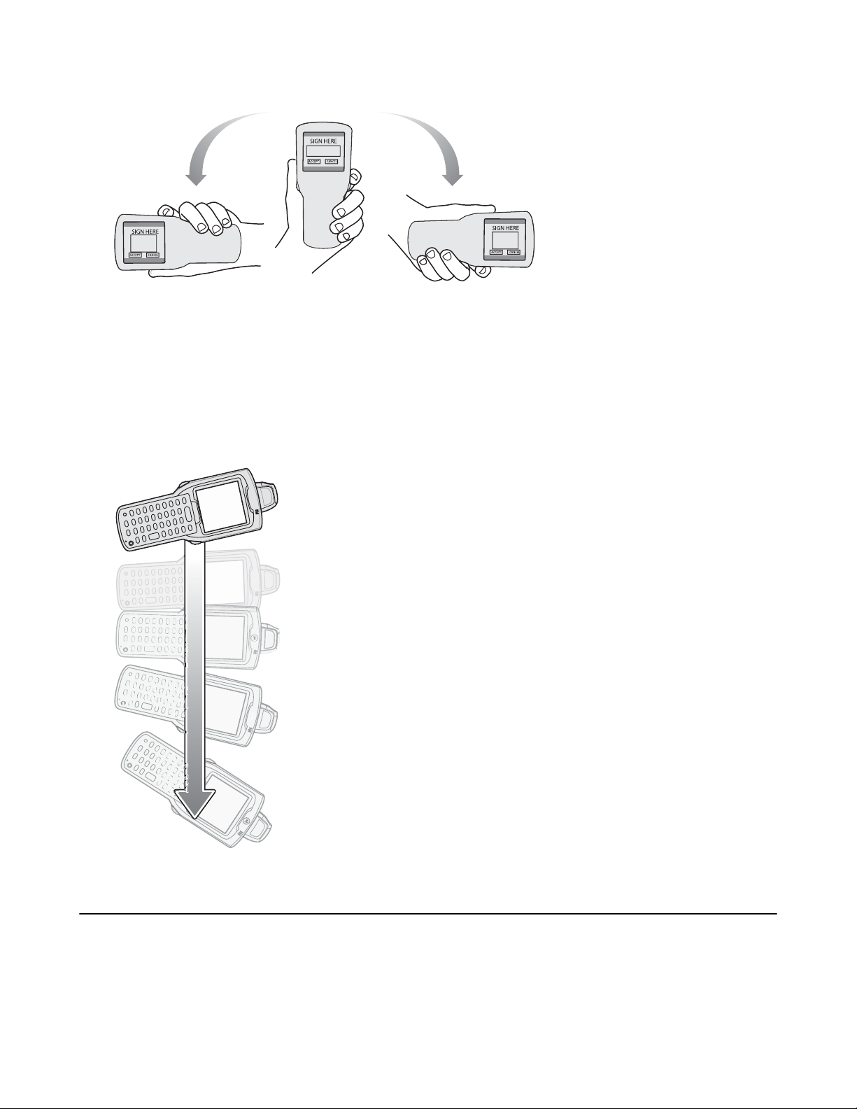
90 | Using the MC32N0 with Windows CE
Figure 82: Display Orientation
Free Fall Detection
IST continuously monitors gravitational force on the MC32N0 according to its current position. When the MC32N0
free falls, IST detects the absence of gravitational force and records the event data if it detects a free fall more than
450 ms, which may indicate nearly a one meter drop. This data can be used as an indicator of potential abuse or
misuse.
IST features a log for recording the free fall events. This log records the date, time and the time period of the free fall.
Figure 83: Free Fall Detection
@
Resetting the MC32N0
If the MC32N0 stops responding to input, reset it. There are two reset functions, warm boot and cold boot. A warm
boot restarts the MC32N0 by closing all running programs. All data that is not saved is lost.
A cold boot also restarts the MC32N0, but erases all stored records and entries from RAM. In addition it returns
formats, preferences and other settings to the factory default settings.
April 2015 | MN000886A01-B
Using the MC32N0 with Windows CE | 91
Perform a warm boot first. If the MC32N0 still does not respond, perform a cold boot.
Performing a Warm Boot
Caution: Files that remain open during a warm boot may not be retained.
Procedure:
1 Press the Power button for five seconds.
2 As soon as the MC32N0 starts to perform a warm boot release the Power button.
Performing a Cold Boot
A cold boot restarts the MC32N0 and erases all user stored records and entries from RAM. Never perform a cold boot
unless a warm boot does not solve the problem.
Caution: Cold boot resets the MC32N0, to the default settings. All added applications and all stored data
are removed. Do not cold boot without support desk approval.
Procedure:
1 Simultaneously press and then release the 1, 9 and Power keys. Do not hold down any other keys or buttons. As
the MC32N0 initializes, the splash window appears for about a minute.
2 Calibrate the touch screen.
WLAN
Wireless Local Area Networks (LANs) allow mobile computers to communicate wirelessly and send captured data to
a host device in real time. Before using the MC32N0 on a WLAN, the facility must be set up with the required
hardware to run the wireless LAN and the MC32N0 must be configured. Refer to the documentation provided with
the access points (APs) for instructions on setting up the hardware.
Note: 802.11d is enabled by default. When enabled, the AP must be configured the same in order to
connect.
To configure the MC32N0, a set of wireless applications provide the tools to configure and test the wireless radio in
the MC32N0. Refer to the Wireless Fusion Enterprise Mobility Suite User Guide for Version X2.01 for information
on configuring wireless profiles. Go to http://www.motorolasolutions.com/support for the latest version of this guide.
See Software Versions on page xii to determine the Fusion version on the MC32N0.
Note: Select the Country for the MC32N0’s country of operation. The access point prompts for the correct
country code on the first login. A warning message also displays stating an incorrect country setting may
result in illegal radio operation. Selecting the correct country is central to legally operating the access point.
Each country has its own regulatory restrictions concerning electromagnetic emissions and the maximum
RF signal that can be transmitted. To ensure compliance with national and local laws, set the country
accurately. MC32N0 users cannot configure their access point until country code is set.
Tap the Signal Strength icon to display the Wireless Launcher menu.
MN000886A01-B | April 2015

92 | Using the MC32N0 with Windows CE
Figure 84: Wireless Applications Menu
Many of the items in the menu invoke one of the Fusion applications. These menu items and their corresponding
applications are summarized below:
• Find WLANs – Invokes the Find WLANs application which displays a list of the WLANs active in your area.
The Wireless Application menu on the task tray provides the following wireless applications:
• Manage Profiles – Invokes the Manage Profiles application (which includes the Profile Editor Wizard) to manage
and edit your list of WLAN profiles.
• Manage Certs – Invokes the Certificate Manager application which allows you to manage certificates used for
authentication.
• Manage PACs – Invokes the PAC Manager application which helps you manage the list of Protected Access
Credentials used with EAP-FAST authentication.
• Options – Invokes the Options application which allows you to configure the Fusion option settings.
• Wireless Status – Invokes the Wireless Status application which allows you to view the status of the current
wireless connection.
• Wireless Diagnostics – Invokes the Wireless Diagnostics application which provides tools with which to
diagnose problems with the wireless connection.
• Log On/Off – Invokes the Network Login dialog which allows you to log on to a particular profile or to log off
from the currently active profile.
Additional Wireless Launcher menu entries include:
• Enable/Disable Radio
• Hide Menu
• Exit
Signal Strength Icon
The Signal Strength icon in the task tray indicates the mobile computer’s wireless signal strength as follows:
Table 19: Signal Strength Icons Descriptions
Icon Status Description
Excellent signal
strength
Very good signal
strength
Wireless LAN network is ready to use.
Wireless LAN network is ready to use.
Table continued…
April 2015 | MN000886A01-B
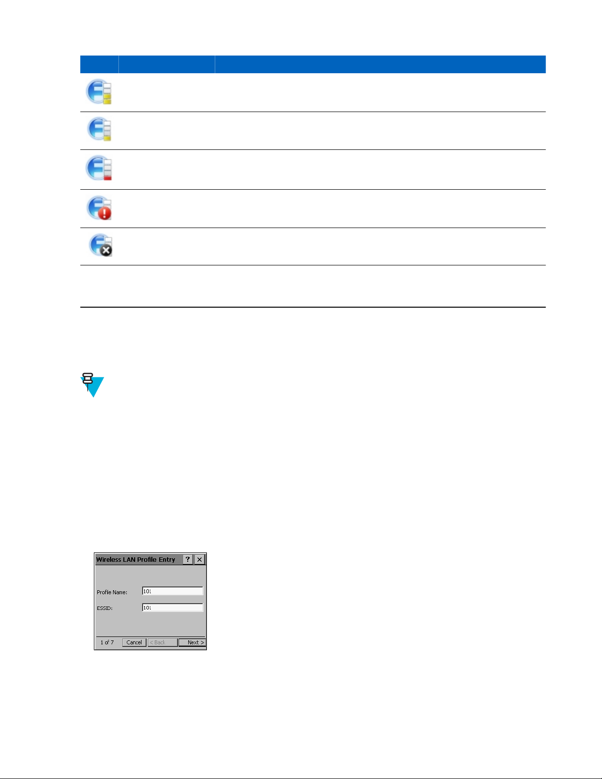
Icon Status Description
Good signal strength Wireless LAN network is ready to use.
Fair signal strength Wireless LAN network is ready to use. Notify the network administrator that the
signal strength is only “Fair”.
Poor signal strength WLAN network is ready to use. Performance may not be optimum. Notify the
network administrator that the signal strength is “Poor”.
Using the MC32N0 with Windows CE | 93
Out-of-network range
(not associated)
The WLAN radio is
disabled.
None The Wireless Launch-
er application was exited.
No WLAN network connection. Notify the network administrator.
WLAN radio is disabled. To enable, choose Enable Radio from the Wireless
Applications menu.
The Wireless Launcher application has been closed. See the Fusion Functions
paragraphs below for how to restart the Wireless Launcher.
Fusion Setup
For detailed WLAN setup using Fusion, refer to the Wireless Fusion Enterprise Mobility Suite User Guide for
Version X2.01.
Note:
Obtain the proper WLAN configuration information from the system administrator prior to performing the
Fusion setup procedures.
The following setup procedure example shows setup of a WLAN using Wired Equivalent Privacy (WEP)
encryption.
Procedure:
1 Touch Fusion icon > Manage Profiles.
2 Touch and hold in the window and select Add from the pop-up menu.
3 In the Profile Name text box enter a name for the profile.
4 In the ESSID text box enter the ESSID.
Figure 85: Profile ID Dialog Box
5 Touch Next.
6 In the Operating Mode drop-down list, select Infrastructure or Ad-hoc.
MN000886A01-B | April 2015
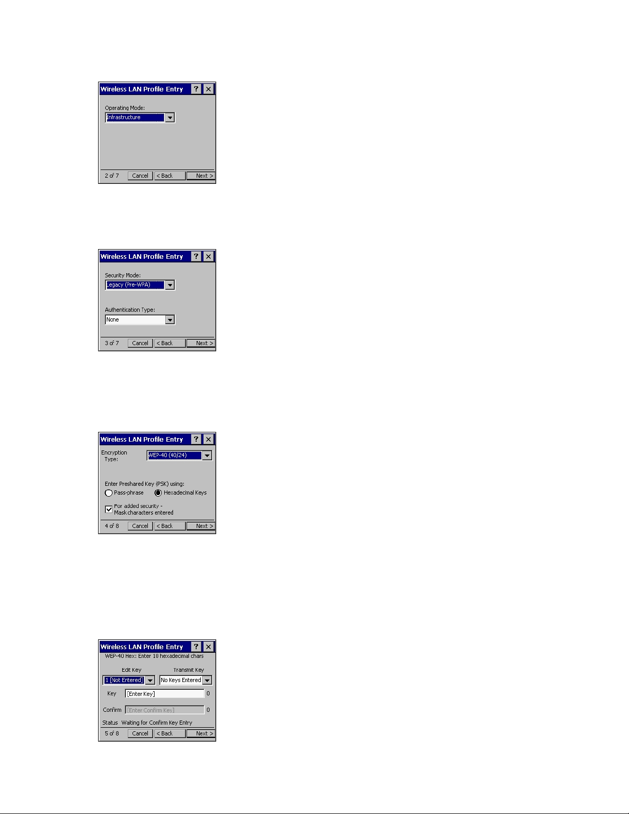
94 | Using the MC32N0 with Windows CE
Figure 86: Operating Mode Dialog Box
7 Touch Next.
8 In the Security Mode drop-down list, select Legacy (Pre-WPA).
Figure 87: Security/Authentication Dialog Box
9 In the Authentication drop-down list, select None.
10 Touch Next.
11 In the Encryption Type drop-down list, select WEP-40 (40/24).
Figure 88: Encryption Dialog Box
12 Select the Pass-phrase or Hexadecimal Keys radio button to indicate whether a pass-phrase or hexadecimal keys
will be entered on the next page.
13 Select the For added security - Mask characters entered check box to hide characters entered. Deselect this to
show characters entered.
14 Touch Next.
Figure 89: WEP-40 WEP Keys Dialog Box
April 2015 | MN000886A01-B
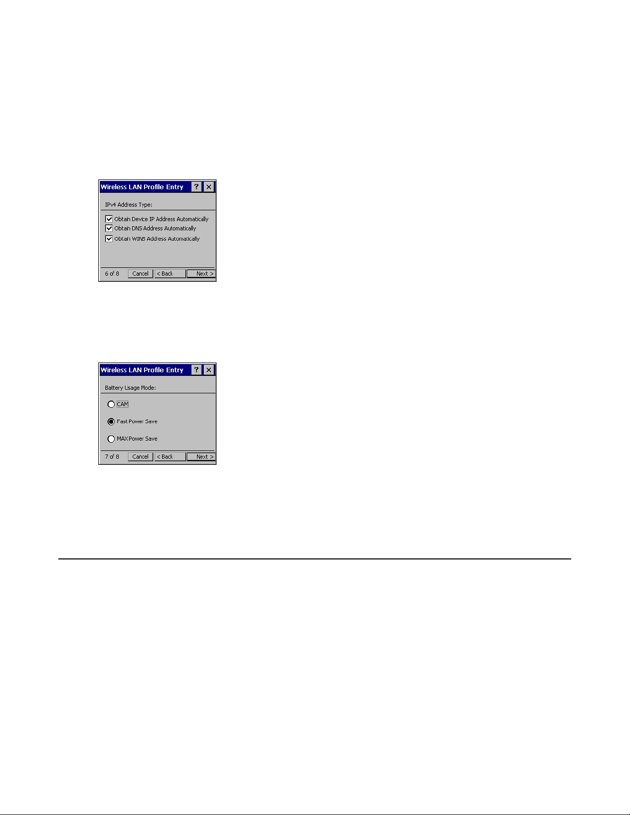
Using the MC32N0 with Windows CE | 95
15 In the Edit Key drop-down list, select the key to enter.
16 In the Key field, enter 10 hexadecimal characters.
17 In the Confirm field, re-enter the key. When the keys match, a message appears indicating that the keys match.
18 Repeat for each WEP key.
19 In the Transmit Key drop-down list, select the key to transmit.
20 Touch Next.
Figure 90: IP Address Entry Dialog Box
21 Ensure that all three check boxes are selected.
22 Touch Next.
23 In the Battery Usage Mode dialog box select a power consumption option.
Figure 91: Battery Usage Dialog Box
24 Touch Next.
25 In the Performance Settings dialog box select either Optimize for Data or Optimize for Voice.
26 Touch Save.
Using Bluetooth with Windows CE
Adaptive Frequency Hopping
Adaptive Frequency Hopping (AFH) is a method of avoiding fixed frequency interferers, and can be used with
Bluetooth voice. All devices in the piconet (Bluetooth network) must be AFH-capable in order for AFH to work.
There is no AFH when connecting and discovering devices. Avoid making Bluetooth connections and discoveries
during critical 802.11b communications. AFH for Bluetooth consists of four main sections:
• Channel Classification - A method of detecting an interference on a channel-by-channel basis, or pre-defined
channel mask.
• Link Management - Coordinates and distributes the AFH information to the rest of the Bluetooth network.
• Hop Sequence Modification - Avoids interference by selectively reducing the number of hopping channels.
• Channel Maintenance - A method for periodically re-evaluating the channels.
When AFH is enabled, the Bluetooth radio “hops around” (instead of through) the 802.11b high-rate channels. AFH
coexistence allows Zebra devices to operate in any infrastructure.
MN000886A01-B | April 2015

96 | Using the MC32N0 with Windows CE
The Bluetooth radio in this device operates as a Class 2 device power class. The maximum output power is 2.5 mW
and the expected range is 10 meters (32.8 ft.). A definition of ranges based on power class is difficult to obtain due to
power and device differences, and whether one measures open space or closed office space.
Note: It is not recommended to perform Bluetooth wireless technology inquiry when high rate 802.11b
operation is required.
Security
The current Bluetooth specification defines security at the link level. Application-level security is not specified. This
allows application developers to define security mechanisms tailored to their specific need. Link-level security occurs
between devices, not users, while application-level security can be implemented on a per-user basis. The Bluetooth
specification defines security algorithms and procedures required to authenticate devices, and if needed, encrypt the
data flowing on the link between the devices. Device authentication is a mandatory feature of Bluetooth while link
encryption is optional.
Pairing of Bluetooth devices is accomplished by creating an initialization key used to authenticate the devices and
create a link key for them. Entering a common personal identification number (PIN) in the devices being paired
generates the initialization key. The PIN is never sent over the air. By default, the Bluetooth stack responds with no
key when a key is requested (it is up to user to respond to the key request event). Authentication of Bluetooth devices
is based-upon a challenge-response transaction. Bluetooth allows for a PIN or passkey used to create other 128-bit
keys used for security and encryption. The encryption key is derived from the link key used to authenticate the pairing
devices. Also worthy of note is the limited range and fast frequency hopping of the Bluetooth radios that makes longdistance eavesdropping difficult.
Recommendations are:
• Perform pairing in a secure environment
• Keep PIN codes private and do not store the PIN codes in the device
•
Implement application-level security.
Bluetooth Profiles
The MC32N0 with WinCE7 supports the following Bluetooth services:
• Microsoft stack:
- Generic Access Profile (GAP) - Use for device discovery and authentication.
- Service Discovery Access Protocol (SDP) - Handles the search for known and specific services as well as
general services.
- Serial Port Profile (SPP) - Sets up a virtual serial port and connects two Bluetooth enabled devices. For
example, connecting the MC32N0 to a printer.
- Headset Profile (HSP) - Allows a hands-free device, such as a Bluetooth headset, to place and receive calls on
the MC32N0.
• StoneStreet stack:
- Generic Access Profile (GAP) - Use for device discovery and authentication.
- Service Discovery Access Protocol (SDP) - Handles the search for known and specific services as well as
general services.
- Serial Port Profile (SPP) - Sets up a virtual serial port and connects two Bluetooth enabled devices. For
example, connecting the MC32N0 to a printer.
- Human Interface Device Profile (HID) - Allows Bluetooth keyboards, pointing devices, gaming devices and
remote monitoring devices to connect to the MC32N0.
- Dial-up Networking (DUN) - Allows the MC32N0 to access the Internet and other dial-up services using a
Bluetooth enabled mobile phone.
- Personal Area Network (PAN) - Allow the use of Bluetooth Network Encapsulation Protocol on Layer 3
protocols for transport over a Bluetooth link.
April 2015 | MN000886A01-B

- General Object Exchange Profile (GOEP) - Provides a basis for other data profiles. Based on OBEX and
sometimes referred to as such.
- Headset Profile (HSP) - Allows a hands-free device, such as a Bluetooth headset, to place and receive calls on
the MC32N0.
- Headset Profile (HSP) - Allows a hands-free device, such as a Bluetooth headset, to place and receive calls on
the MC32N0.
MotoBTUI Application
Use the MotoBTUI application to:
• Turn the Bluetooth radio on and off
View device information
•
• Control device status
• Generate a pairing bar code
• Cofigure FIPS key
• Discover and pair with other Bluetooth devices (using the Microsoft stack).
Figure 92: MotoBTUI Window
Using the MC32N0 with Windows CE | 97
Viewing Device Information
Procedure:
1 Touch Start > Programs > MotoBTUI.
2 Touch My Device information.
The Device Information displays:
• Device Name
• HCI version number
• LMP version number
•
Bluetooth chip manufacturer name
• BT UI version number.
MN000886A01-B | April 2015

98 | Using the MC32N0 with Windows CE
Figure 93: MotoBTUI Window
3 Touch the Back button to return to the MotoBTUI window.
FIPS Configuration
Note: By default the MC32N0 has a Federal Information Processing Standards (FIPS) key installed. If
required, the user can generate a new FIPS key. If a new key is generated on the MC32N0, the same key is
required to be used on the other Bluetooth device. The user must transfer the key to the other device.
Generating a New FIPS Key Automatically
Procedure:
1 Touch Start > Programs > MotoBTUI.
2 Touch FIPS Configuration.
Figure 94: AES Key Window
3 Touch Generate Key.
4 Touch the SetUp Key button. A new key is generated. The key file, NewAESKey.reg, is created in the /
Application folder.
5 Touch the Back button to return to the MotoBTUI window.
Generating a New FIPS Key Manually
Procedure:
1 Touch Start > Programs > MotoBTUI.
2 Touch FIPS Configuration.
3 Touch Enter Key.
4 In the text box, enter a key.
April 2015 | MN000886A01-B

Using the MC32N0 with Windows CE | 99
5 Touch the SetUp Key button. A new key is generated. The key file, NewAESKey.reg, is created in the /
Application folder.
6 Touch the Back button to return to the MotoBTUI window.
Transferring a New FIPS Key to Another Bluetooth Device
Procedure:
1 Copy the NewAESKey.reg file from the MC32N0 to the other Bluetooth device. Place the file into the /
Application folder..
2 Navigate to the /Application folder..
3 Locate the NewAESKey.reg file and touch the filename. The RegMerge confirmation box displays..
4 Touch Yes.
5 Perform a warm boot.
DeviceStatus
Use the Device Status option to set if the MC32N0 would be seem by other Bluetooth devices. Touch the Device
Status option to toggle the MC32N0 from Hidden to Discoverable.
Using Microsoft Bluetooth Stack with Windows CE
The following sections provide information on using the Microsoft Bluetooth stack with Windows CE operating
system.
Bluetooth Radio Power – Windows CE
Turn off the Bluetooth radio to save power or if entering an area with radio restrictions (e.g., an airplane). When the
radio is off, other Bluetooth devices cannot see or connect to the MC32N0. Turn on the Bluetooth radio to exchange
information with other Bluetooth devices (within range). Communicate only with Bluetooth radios in close proximity.
Note: To achieve the best battery life turn off radios when not in use.
Enabling Bluetooth
Procedure:
1 Touch Start > Settings > Control Panel > MotoBTUI.
Figure 95: Enable Bluetooth
2 Touch Off tab in the top left corner. The Bluetooth icon appears in the task tray.
MN000886A01-B | April 2015
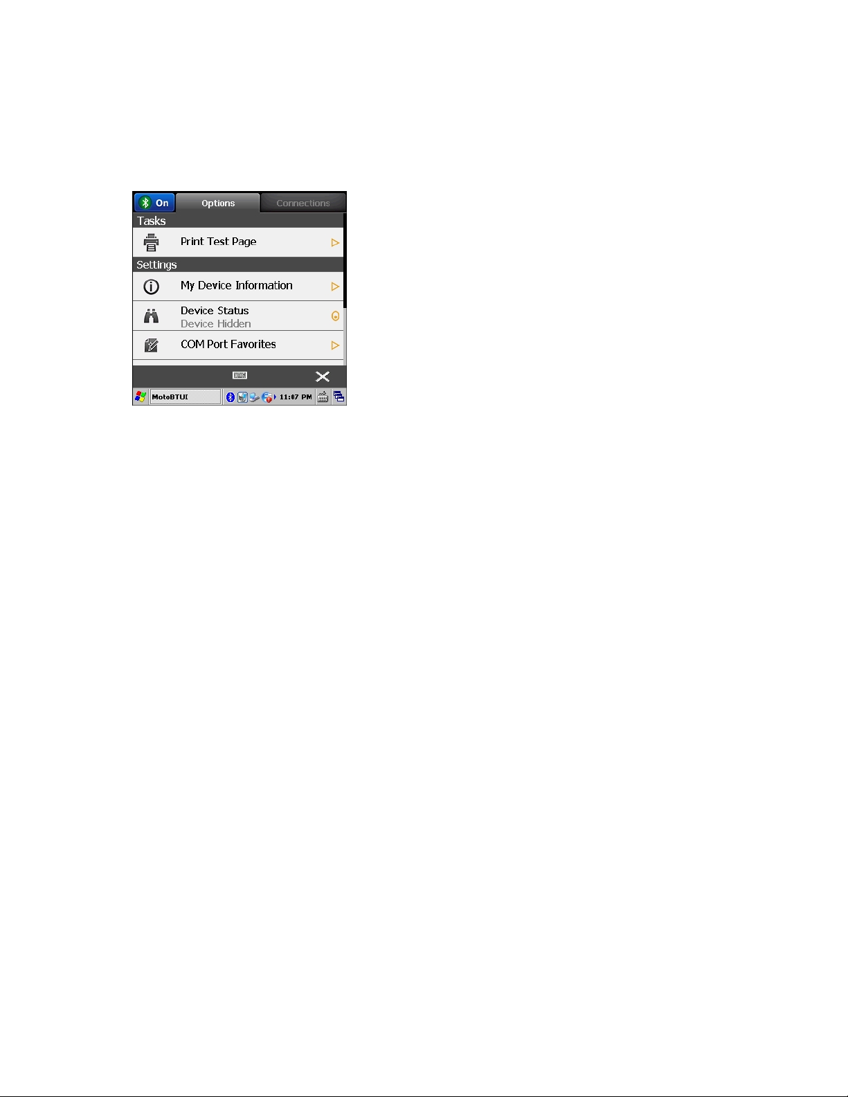
100 | Using the MC32N0 with Windows CE
Disabling Bluetooth
Procedure:
1 Touch Start > Settings > Control Panel > MotoBTUI.
Figure 96: Enable Bluetooth
2 Touch On tab in the top left corner. The Bluetooth icon is removed from the task tray.
Power Modes
The Bluetooth radio switches between normal and low power modes automatically. When data transfer is required,
the radio goes into normal mode. After five seconds of inactivity, the radio goes into low power mode.
Discovering Bluetooth Device(s)
The MC32N0 can receive information from discovered devices without bonding. However, once bonded, the
MC32N0 and a bonded device exchange information automatically when you turn the Bluetooth radio on.
Procedure:
1 Ensure that Bluetooth is enabled on both devices.
2 Ensure that the Bluetooth device to discover is in discoverable and connectable modes.
3 Ensure that the two devices are within 10 meters (32.8 feet) of one another.
4 Touch Start > Settings > Control Panel > MotoBTUI.
5 If Bluetooth is off, select the Bluetooth icon to turn Bluetooth on.
6 Select the Connections tab. The MC32N0 begins searching for discoverable Bluetooth devices in the area.
Discovered devices appear in the list.
April 2015 | MN000886A01-B
 Loading...