


Wireless Fusion Enterprise
Mobility Suite
User Guide for Version 3.00


Wireless Fusion Enterprise Mobility Suite
User Guide for Version 3.00
72E-122495-02
Rev. A
March 2015

ii Wireless Fusion Enterprise Mobility Suite User Guide
© 2015 ZIH Corp and/or its affiliates. All rights reserved.
No part of this publication may be reproduced or used in any form, or by any electrical or mechanical means,
without permission in writing from Zebra. This includes electronic or mechanical means, such as photocopying,
recording, or information storage and retrieval systems. The material in this manual is subject to change
without notice.
The software is provided strictly on an “as is” basis. All software, including firmware, furnished to the user is on
a licensed basis. Zebra grants to the user a non-transferable and non-exclusive license to use each software
or firmware program delivered hereunder (licensed program). Except as noted below, such license may not be
assigned, sublicensed, or otherwise transferred by the user without prior written consent of Zebra. No right to
copy a licensed program in whole or in part is granted, except as permitted under copyright law. The user shall
not modify, merge, or incorporate any form or portion of a licensed program with other program material, create
a derivative work from a licensed program, or use a licensed program in a network without written permission
from Zebra. The user agrees to maintain Zebra’s copyright notice on the licensed programs delivered
hereunder, and to include the same on any authorized copies it makes, in whole or in part. The user agrees not
to decompile, disassemble, decode, or reverse engineer any licensed program delivered to the user or any
portion thereof.
Zebra reserves the right to make changes to any software or product to improve reliability, function, or design.
Zebra does not assume any product liability arising out of, or in connection with, the application or use of any
product, circuit, or application described herein.
No license is granted, either expressly or by implication, estoppel, or otherwise under any Zebra, intellectual
property rights. An implied license only exists for equipment, circuits, and subsystems contained in Zebra
products.

Revision History
Changes to the original manual are listed below:
Change Date Description
-01 Rev. A 06/25/09 Initial release.
-01 Rev. B 02/16/10 Add Windows Mobile 6.5 support for launching Fusion applications.
-02 Rev. A 03/28/15 Zebra rebranding.
iii

iv Wireless Fusion Enterprise Mobility Suite User Guide

Table of Contents
Revision History.................................................................................................................................... iii
About This Guide
Introduction ........................................................................................................................................... ix
Chapter Descriptions ............................................................................................................................ ix
Notational Conventions......................................................................................................................... x
Related Documents .............................................................................................................................. x
Chapter 1: Getting Started
Introduction .......................................................................................................................................... 1-1
Configuring the Infrastructure .............................................................................................................. 1-1
Fusion Overview .................................................................................................................................. 1-1
Fusion Signal Strength Icon ................................................................................................................. 1-2
Fusion Functions ................................................................................................................................. 1-2
Enable/Disable Radio .................................................................................................................... 1-3
Hide Menu ...................................................................................................................................... 1-4
Exit ................................................................................................................................................. 1-4
Windows Mobile 6.5 Default Today Screen Plug-in ............................................................................. 1-4
Minimum Setup .................................................................................................................................... 1-5
Chapter 2: Find WLAN Application
Introduction .......................................................................................................................................... 2-1
Chapter 3: Manage Profiles Application
Introduction .......................................................................................................................................... 3-1
Connect to a Profile ............................................................................................................................. 3-2
Editing a Profile .................................................................................................................................... 3-3
Creating a New Profile ......................................................................................................................... 3-3
Deleting a Profile ................................................................................................................................. 3-4
Ordering Profiles .................................................................................................................................. 3-4

vi Wireless Fusion Enterprise Mobility Suite User Guide
Export a Profile .................................................................................................................................... 3-4
Profile Roaming ................................................................................................................................... 3-4
Chapter 4: Profile Editor Wizard
Introduction .......................................................................................................................................... 4-1
Profile Name ........................................................................................................................................ 4-1
Operating Mode ................................................................................................................................... 4-2
Ad-hoc ................................................................................................................................................. 4-3
Security Mode ...................................................................................................................................... 4-4
Authentication Type ............................................................................................................................. 4-6
CCX Options ........................................................................................................................................ 4-6
Tunneled Authentication ...................................................................................................................... 4-7
User Certificate Selection .................................................................................................................... 4-9
User Certificate Installation ............................................................................................................ 4-9
Server Certificate Selection ........................................................................................................... 4-11
Server Certificate Installation ......................................................................................................... 4-11
User Name ..................................................................................................................................... 4-12
Password ............................................................................................................................................. 4-13
Advanced Identity ................................................................................................................................ 4-14
Credential Cache Options .................................................................................................................... 4-15
Encryption ............................................................................................................................................ 4-17
Hexadecimal Keys ......................................................................................................................... 4-19
Pass-phrase Dialog ........................................................................................................................ 4-20
IPv4 Address Entry .............................................................................................................................. 4-21
Transmit Power .................................................................................................................................... 4-24
Battery Usage ...................................................................................................................................... 4-25
Chapter 5: Manage Certificates Application
Introduction .......................................................................................................................................... 5-1
Certificate Properties ........................................................................................................................... 5-2
Import a Certificate .............................................................................................................................. 5-3
Delete a Certificate .............................................................................................................................. 5-5
Chapter 6: Manage PACs Application
Introduction .......................................................................................................................................... 6-1
PAC Properties .................................................................................................................................... 6-2
Delete PAC .......................................................................................................................................... 6-2
Import PAC .......................................................................................................................................... 6-3
Chapter 7: Options
Introduction .......................................................................................................................................... 7-1
Op (Operating) Mode Filtering ............................................................................................................. 7-1
Regulatory Options .............................................................................................................................. 7-2
Band Selection ..................................................................................................................................... 7-2
System Options ................................................................................................................................... 7-3
Auto PAC Settings ............................................................................................................................... 7-3

Table of Contents vii
IPv6 ...................................................................................................................................................... 7-5
Change Password ............................................................................................................................... 7-5
Export .................................................................................................................................................. 7-6
Chapter 8: Wireless Status Application
Introduction .......................................................................................................................................... 8-1
Signal Strength Window ................................................................................................................. 8-2
Current Profile Window .................................................................................................................. 8-3
IPv4 Status Window ................................................................................................................. 8-4
IPv6 Status Window ....................................................................................................................... 8-5
Wireless Log Window .................................................................................................................... 8-7
Saving a Log ............................................................................................................................ 8-8
Clearing the Log ....................................................................................................................... 8-8
Logos & Certifications Window ...................................................................................................... 8-8
Versions Window ........................................................................................................................... 8-9
Chapter 9: Wireless Diagnostics Application
Introduction .......................................................................................................................................... 9-1
ICMP Ping Window ........................................................................................................................ 9-1
Graphs ........................................................................................................................................... 9-3
Trace Route Window ..................................................................................................................... 9-3
Known APs Window ....................................................................................................................... 9-4
Chapter 10: Log On/Off Application
Introduction .......................................................................................................................................... 10-1
Logging On .......................................................................................................................................... 10-1
Logging Off .................................................................................................................................... 10-3
Chapter 11: Persistence
Introduction .......................................................................................................................................... 11-1
Persisting Fusion Settings ................................................................................................................... 11-1
Returning to Factory Default Settings .................................................................................................. 11-2
Chapter 12: Registry Controlled Features
NPCS ................................................................................................................................................... 12-1
FIPS 140-2 ..................................................................................................................................... 12-2
WMM UAPSD ...................................................................................................................................... 12-2
Chapter 13: Configuration Examples
Introduction .......................................................................................................................................... 13-1
EAP–FAST/MS Chap v2 Authentication .............................................................................................. 13-1
Glossary

viii Wireless Fusion Enterprise Mobility Suite User Guide
Index

About This Guide
Introduction
This guide provides information about using the Fusion Wireless Companion software on a Zebra mobile computer.
NOTE Screens and windows pictured in this guide are samples and can differ from actual screens.
This guide describes the functionally using Windows Mobile operating system. Functionality for the
WIndows CE operating system may differ.
Chapter Descriptions
Topics covered in this guide are as follows:
•
Chapter 1, Getting Started provides an overview of the Fusion Wireless Companion software.
•
Chapter 2, Find WLAN Application provides information about the Find WLAN application.
•
Chapter 3, Manage Profiles Application provides information about managing profiles.
•
Chapter 4, Profile Editor Wizard explains how to configure a profile.
•
Chapter 5, Manage Certificates Application explains how to manage certificates.
•
Chapter 6, Manage PACs Application explains how to manage PACs.
•
Chapter 7, Options explains how to configure the Fusion options.
•
Chapter 8, Wireless Status Application describes how to get status about the wireless connection.
•
Chapter 9, Wireless Diagnostics Application describes tools to help diagnose problems with the wireless
connection.
•
Chapter 10, Log On/Off Application explains how to log on and off the wireless network.
•
Chapter 11, Persistence explains how to persist Fusion data and settings across a clean/cold boot.
•
Chapter 12, Registry Controlled Features describes Fusion features that are controlled by registry settings.
•
Chapter 13, Configuration Examples provides examples for setting up profiles with various authentication
and encryption types.

x Wireless Fusion Enterprise Mobility Suite User Guide
Notational Conventions
The following conventions are used in this document:
•
Italics are used to highlight the following:
• Chapters and sections in this and related documents
• Dialog box, window and screen names
• Icons on a screen.
•
Bold text is used to highlight the following:
• Key names on a keypad
• Button names on a screen or window.
• Drop-down list and list box names
• Check box and radio button names
•
bullets (•) indicate:
• Action items
• Lists of alternatives
• Lists of required steps that are not necessarily sequential
•
Sequential lists (e.g., those that describe step-by-step procedures) appear as numbered lists.
NOTE This symbol indicates something of special interest or importance to the reader. Failure to read the note
will not result in physical harm to the reader, equipment or data.
CAUTION This symbol indicates that if this information is ignored, the possibility of data or material damage may
WARNING! This symbol indicates that if this information is ignored the possibility that serious personal
Related Documents
•
Enterprise Mobility Developer Kit for C (EMDK for C), available at: http://www.zebra.com/support.
•
ActiveSync 4.x software, available at: http://www.microsoft.com.
For the latest version of this guide and all guides, go to: http://www.zebra.com/support.
occur.
injury may occur.

Chapter 1 Getting Started
Introduction
Each Zebra mobile computer has a wireless local area network (WLAN) interface. This WLAN interface is
controlled by a suite of application software known as Fusion Wireless Companion. The Fusion software allows the
user to configure and control the wireless radio in order to securely connect to the WLAN infrastructure. This guide
enables the user to configure the mobile computer so that it can connect properly to a WLAN. This guide describes
how to use the Fusion software.
Configuring the Infrastructure
WLANs allow mobile computers to communicate wirelessly. Before using the mobile computer on a WLAN, the
facility must be set up with the required hardware to run the WLAN (sometimes known as infrastructure). The
infrastructure and the mobile computer must both be properly configured to enable this communication.
Refer to the documentation provided with the infrastructure (access points (APs), access ports, switches, Radius
servers, etc.) for instructions on how to set up the infrastructure.
Once you have set up the infrastructure to enforce your chosen WLAN security scheme, use the Fusion software to
configure the mobile computer to match.
Fusion Overview
The Fusion software contains applications with which to create wireless profiles. Each profile specifies the security
parameters to use for connecting to a particular WLAN as identified by its ESSID. The Fusion software also allows
the user to control which profile out of a set of profiles is used to connect. Other Fusion applications allow the user
to monitor the status of the current WLAN connection and to invoke diagnostic tools for troubleshooting.
The Fusion applications are typically accessed through the pop-up menu associated with the Fusion Signal
Strength icon. This icon appears in the bottom right hand corner of the screen. To invoke the Fusion Wireless
Applications menu, tap the icon.
1 - 2 Wireless Fusion Enterprise Mobility Suite User Guide
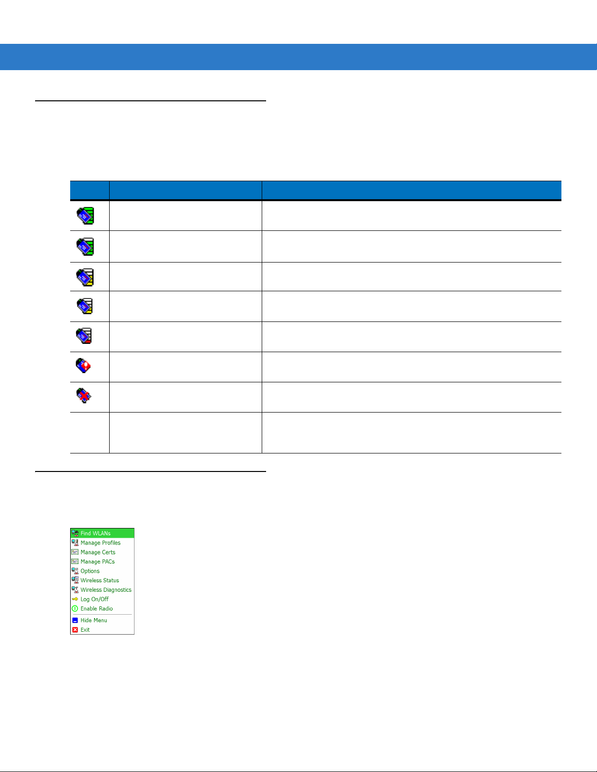
Fusion Signal Strength Icon
The shape and color of the Signal Strength icon provides information about the received wireless signal strength
for the WLAN connection. Table 1-1 describes the different icons and their meanings.
Table 1-1
Icon Status Description
None The Wireless Launcher
Signal Strength Icons Descriptions
Excellent signal strength WLAN network is ready to use.
Very good signal strength WLAN network is ready to use.
Good signal strength WLAN network is ready to use.
Fair signal strength WLAN network is ready to use. Notify the network administrator that
the signal strength is only “Fair”.
Poor signal strength WLAN network is ready to use. Performance may not be optimum.
Notify the network administrator that the signal strength is “Poor”.
Out-of-network range (not
associated)
The WLAN radio is disabled. The WLAN radio is disabled. To enable, choose Enable Radio from
application was exited.
No WLAN network connection. Notify the network administrator.
the Wireless Applications menu.
The Wireless Launcher application has been closed. See the
Fusion Functions paragraphs below for how to restart the Wireless
Launcher.
Fusion Functions
Tap the Signal Strength icon to display the Wireless Launcher menu.
Figure 1-1
Many of the items in the menu invoke one of the Fusion applications. These menu items and their corresponding
applications are summarized below:
•
Wireless Launcher Menu
Find WLANs – Invokes the Find WLANs application which displays a list of the WLANs active in your area.

Getting Started 1 - 3
•
Manage Profiles – Invokes the Manage Profiles application (which includes the Profile Editor Wizard) to
manage and edit your list of WLAN profiles.
•
Manage Certs – Invokes the Certificate Manager application which allows you to manage certificates used
for authentication.
•
Manage PACs – Invokes the PAC Ma n a g er application which helps you manage the list of Protected Access
Credentials used with EAP-FAST authentication.
•
Options – Invokes the Options application which allows you to configure the Fusion option settings.
•
Wireless Status – Invokes the Wireless Status application which allows you to view the status of the current
wireless connection.
•
Wireless Diagnostics – Invokes the Wireless Diagnostics application which provides tools with which to
diagnose problems with the wireless connection.
•
Log On/Off – Invokes the Network Login dialog which allows you to log on to a particular profile or to log off
from the currently active profile.
Each of the items above has a chapter devoted to it in this guide.
Additional Wireless Launcher menu entries include:
•
Enable/Disable Radio
•
Hide Menu
•
Exit.
Enable/Disable Radio
To turn the WLAN radio off, tap the Signal Strength icon and select Disable Radio.
Figure 1-2
Disable Radio
To turn the WLAN radio on, tap the Signal Strength icon and select Enable Radio.

1 - 4 Wireless Fusion Enterprise Mobility Suite User Guide
Figure 1-3
Also note that the radio may be enabled or disabled using the Wireless Manager screen.
Enable Radio
Hide Menu
To hide the menu tap Hide in the menu.
Exit
Ta p Exit to close the menu and exit the Wireless Launcher application. A dialog appears to confirm exiting the
Wireless Launcher application. Tap Yes to exit. This closes the Wireless launcher application and removes the
Signal Strength icon from the screen.
To restart the Wireless Launcher application and redisplay the Signal Strength icon:
1. Ta p Start > Programs > Wireless Companion icon > Wireless Launch icon.
2. Ta p ok twice to close the windows.
3. The Signal Strength icon appears on the screen.
Windows Mobile 6.5 Default Today Screen Plug-in
The interface to the Signal Strength icon and Wireless Launcher has changed in the Windows Mobile 6.5 default
Today screen. To view the Wireless Launcher, select the Fusion plug-in on the Today screen and tap the Fusion
Menu soft key.

Getting Started 1 - 5
Figure 1-4
Functionality of this dialog is similar to the Wireless Launch menu. Drag the window up and down to view all menu
items. Tap the icon next to the item to open it.
Figure 1-5
Fusion Plug-in on Today Screen
Wireless Launcher Window
Minimum Setup
Below is a list of the minimum effort to achieve a wireless connection. Note that there are many discrete nuances
that may affect the performance of your wireless connection that might be missed if you do not consider them
carefully.
You will need to create a profile. It is recommended that you read the profile editor chapter.
1. Find out from your IT administrator what the connection settings should be (Service Set Identifier (SSID),
Enterprise or Personal, 1x type, tunnel type, certificate requirements,
requirements). Note that not all of the items listed may be relevant.
2. Create the profile using the information provided by the IT administrator.
3. Enter the Manage Profile screen, select the profile (press and hold), and select the Connect option in the
context menu that appears.
Protected Access Credentials
(PAC)

1 - 6 Wireless Fusion Enterprise Mobility Suite User Guide

Chapter 2 Find WLAN Application
Introduction
Use the Find WLANs application to discover available networks in the vicinity of your and mobile computer. To
open the Find WLANs application, tap the Signal Strength icon > Find WLANs. The Find WLANs window
displays.
Figure 2-1
The Find WLANs list displays:
•
•
•
•
Find WLANs Window
WLAN Networks - Available wireless networks, (both infrastructure and Ad-hoc) with icons that indicate
signal strength and encryption. The signal strength and encryption icons are described in Table 2-1 and
Table 2-2.
Network Type - Type of network. 802.11(a), 802.11(b) or 802.11(g).
Channel - Channel on which the AP/Ad-hoc peer is transmitting.
Signal Strength - The signal strength of the signal from the AP/Ad-hoc peer.

2 - 2 Wireless Fusion Enterprise Mobility Suite User Guide
.
Table 2-1
Signal Strength Icon
Icon Description
Excellent signal
Very good signal
Good signal
Fair signal
Poor signal
Out of range or no signal
Table 2-2
Encryption Icon
Icon Description
No encryption. WLAN is an infrastructure network.
WLAN is an Ad-hoc network.
WLAN uses encryption. WLAN is an infrastructure network.
Tap-and-hold on a WLAN network to open a pop-up menu which provides three options: Connect to, Create
profile and Refresh.
Figure 2-2
Find WLANs Menu.
NOTE The number of WLANs (ESSIDs) that can be detected by the wireless radio at one time is limited. If you have
a large number of WLANs active in your area, the Find WLANs window may not display them all.
If you do not see your ESSID, try a Refresh. If your ESSID is still not displayed and you wish to create or
connect to a profile for it, you will need to use the Manage Profiles application.
Select Connect to to view the list of existing profiles matching the select ESSID. The mobile computer connects to
the given profile upon selection.

Find WLAN Application 2 - 3
Select Create profile to create a new WLAN profile for that network. This starts the Profile Editor Wizard which
allows you to configure the security parameters that your mobile computer will use for the selected network. After
editing the profile, the mobile computer automatically connects to this new profile.
NOTE A warning displays when connecting to an unsecure (or open) network via the Find WLANs application. For
open WLANs, the profile’s settings will take on automatically generated default values. If you wish to manually
configure the settings, uncheck the Use Default configuration checkbox.
Figure 2-3
Warning Notice
Select Refresh to refresh the WLAN list.

2 - 4 Wireless Fusion Enterprise Mobility Suite User Guide

Chapter 3 Manage Profiles Application
WirelessOutofBoxMagic
Introduction
A profile is a set of operating parameters that define how the mobile computer will connect to a specific WLAN.
Create different profiles for use in different network environments. The Manage Profiles application displays the
list of user-created wireless profiles. You may have a maximum of 32 profiles at any one time. To open the Manage
Profiles application, tap the Signal Strength icon > Manage Profiles.
Figure 3-1
Icons next to each profile identify the profile’s current state.
Table 3-1
Icon Description
No Icon Profile is not selected, but enabled.
Manage Profiles Window
Profile Icons
Profile is disabled.
Profile is cancelled. A cancelled profile is disabled until you connect to it, either by selecting Connect
from the pop-up menu, or by using the Log On/Off application.
3 - 2 Wireless Fusion Enterprise Mobility Suite User Guide
WirelessOutofBoxMagic
Table 3-1
Icon Description
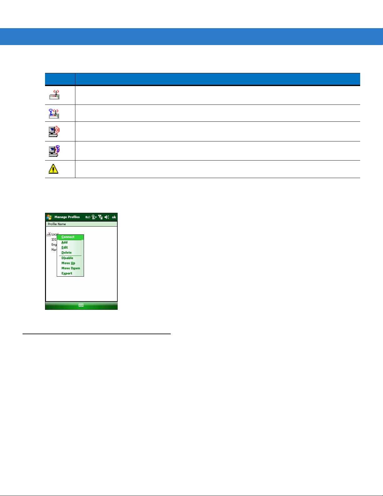
You can perform various operations on the profiles in the list. To operate on an existing profile, tap and hold it in the
list and select an option from the menu to connect, edit, disable (enable), or delete the profile. (Note that the
Disable menu item changes to Enable if the profile is already disabled.)
Profile Icons (Continued)
Profile is in use and describes an infrastructure profile not using security.
Profile is in use and describes an infrastructure profile using security.
Profile is in use and describes an ad-hoc profile not using security.
Profile is in use and describes an ad-hoc profile using security.
Profile is not valid in the regulatory domain in which the device is currently operating.
Figure 3-2
Connect to a Profile
Tap and hold a profile and select Connect from the pop-up menu to set this as the active profile.
Manage Profiles Context Menu

Manage Profiles Application 3 - 3
WirelessOutofBoxMagic
WirelessOutofBoxMagic
Figure 3-3
Once selected, the mobile computer uses the settings configured in the profile (i.e., authentication, encryption,
ESSID, IP Config, power consumption, etc.) to connect to a WLAN.
Manage Profiles - Connect
Editing a Profile
Tap and hold a profile and select Edit from the pop-up menu.This will invoke the Profile Wizard where the profile
settings are configured.
Creating a New Profile
To create a new profile tap and hold anywhere in the Manage Profiles window and select Add from the pop-up
menu.
Figure 3-4
Selecting Add invokes the Profile Wizard wherein the settings for the new profile are configured, such as profile
name, ESSID, security, network address information, and the power consumption level.
Manage Profiles - Add
3 - 4 Wireless Fusion Enterprise Mobility Suite User Guide
Deleting a Profile
To delete a profile from the list, tap and hold the profile and select Delete from the pop-up menu. A confirmation
dialog box appears.
Ordering Profiles
The profiles are listed in priority order for use by the automatic Profile Roaming feature (see Profile Roaming
below). Change the order by moving profiles up or down. Tap and hold a profile from the list and select Move Up or
Move Down from the pop-up menu.
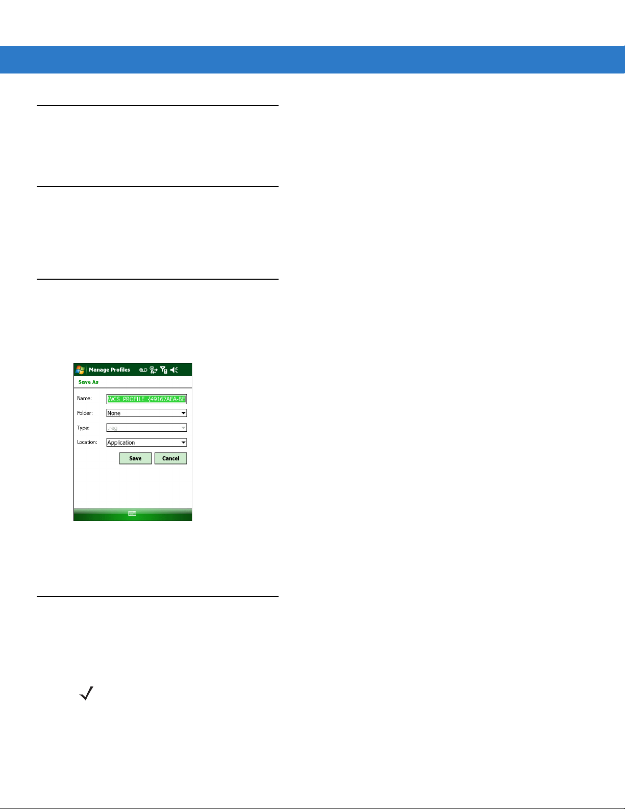
Export a Profile
To export a profile to a registry file, tap and hold a profile from the list and select Export from the pop-up menu. The
Save As dialog box displays with the Application folder and a default name of WCS_PROFILE{profile GUID}.reg
(Globally Unique Identifier).
Figure 3-5
If required, change the name in the Name field and tap Save. A confirmation dialog box appears after the export
completes.
Save As Dialog Box
Profile Roaming
Profile Roaming attempts to automatically select and connect to a profile from the profile list displayed in the
Manage Profiles window. The Profile Roaming algorithm uses the order of the profiles in the profile list to
determine the order in which profiles are tried.
NOTE Profile Roaming must be enabled in the Options application. See Chapter 7, Options.
The Profile Roaming algorithm makes two passes through the profile list. The first pass attempts to connect only to
profiles that specify ESSIDs that can be detected by the wireless radio. If no connection is made, a second pass
through the list is performed attempting to connect to those profiles that were not tried in the first pass. The Profile

Manage Profiles Application 3 - 5
Roaming algorithm will only attempt to connect to a profile for which it is not necessary to prompt the user for
credentials (i.e., username and password). This includes:
•
A profile that does not require credentials.
•
A device profile. A device profile is one in which the username and password have been pre-entered directly
into the profile. (A profile with the username specified but with the password field left empty is still considered
a device profile since an empty password is considered a valid password.)
•
A user profile with cached credentials. A user profile is one in which the username and password have not
been pre-entered into the profile. A profile has cached credentials if the user has entered credentials for the
profile via the Network Login dialog. When a profile has cached credentials, the user is said to have logged
on to the profile. See Chapter 10, Log On/Off Application for more information.
The Profile Roaming algorithm will not attempt to connect to:
•
A profile that specifies EAP-GTC for its Tunnel Authentication Type and Token (as opposed to Static) for its
password type. See Tunneled Authentication on page 4-7 for more information.
•
A user profile without cached credentials.
•
A user profile that has cached credentials but that also has the At-Connect option enabled. See Credential
Cache Options on page 4-15 for more information.
•
A device profile that has cached credentials because the user has logged on to it (called a user-override
profile), but that also has the At-Connect option enabled.
•
A profile that has been disabled.
•
A profile that has been cancelled.
•
A profile whose Country setting does not allow the profile to be used in the country in which the mobile
computer is being operated. See Operating Mode on page 4-2 for more information.
The Profile Roaming algorithm is invoked whenever the mobile computer becomes disconnected (disassociated)
from the current WLAN.

3 - 6 Wireless Fusion Enterprise Mobility Suite User Guide

Chapter 4 Profile Editor Wizard
Introduction
Use the Profile Editor Wizard to create a new WLAN profile or edit an existing profile. If editing a profile, the fields reflect the current settings for that profile. If creating a new profile, default values appear in the fields.
Navigate through the wizard using the Next and Back buttons. An indicator in the bottom left corner tracks the
number of pages traversed and total number of pages required to complete the current profile configuration. Tap X
or the Cancel button to quit. On the confirmation dialog box, tap No to return to the wizard or tap Yes to quit and
return to the Manage Profiles window. See Chapter 3, Manage Profiles Application for instructions on navigating
to and from the Profile Editor Wizard.
Profile Name
In the Profile Name dialog box in the Profile Editor Wizard, enter the profile name and the ESSID.
Figure 4-1
Table 4-1
Profile Name The user-friendly name you wish to give the profile. The profile name is limited to 64
ESSID The ESSID is the 802.11 extended service set identifier. The ESSID is a 32-character
Profile Name Dialog Box
Profile Name Fields
Field Description
characters. Example: The Public LAN.
(maximum) case sensitive string identifying the WLAN, and must match the AP ESSID for the
mobile computer to communicate with the AP.

4 - 2 Wireless Fusion Enterprise Mobility Suite User Guide
NOTE Two profiles with the same user friendly name are acceptable but not recommended.
Ta p Next. The Operating Mode dialog box displays.
Operating Mode
Use the Operating Mode dialog box to select the operating mode (Infrastructure or Ad-hoc) and the country
location.
Figure 4-2
Table 4-2
Operating Mode Select Infrastructure to enable the mobile computer to transmit and receive data with an AP.
Country Country determines if the profile is valid for the country of operation. The profile country must
Table 4-3 defines the regulatory validity of profiles that use infrastructure mode:
Table 4-3
802.11d Settings
Enabled Any Country N/A Country X Valid
Enabled Country X N/A Country X Valid
Operating Mode Dialog Box
Operating Mode Fields
Field Description
Infrastructure is the default mode.
Select Ad-hoc to enable the mobile computer to form its own local network where mobile
computers communicate peer-to-peer without APs using a shared ESSID.
match the country in the options page or it must match the acquired country if 802.11d is
enabled.Note that the 802.11d setting only applies to infrastructure profiles, not to Ad-hoc
profiles.
Profile Regulatory Validity for Infrastructure Mode
Profile Country
Settings
Fusion Options
Country Settings
Country Code
Acquired from
Infrastructure
Regulatory
Validity
Enabled Country X N/A Country Y Invalid
Disabled Any Country Country Y N/A Valid
Disabled Country X Country X N/A Valid
Disabled Country X Country Y N/A Invalid

Table 4-4 defines the regulatory validity of profiles that use ad-hoc mode:
Profile Editor Wizard 4 - 3
Table 4-4
Ta p Next. If Ad-hoc mode was selected the Ad-hoc Channel dialog box displays. If Infrastructure mode was
selected the Security Mode dialog box displays. See Encryption on page 4-17 for instruction on setting up
authentication.
Ad-hoc
Use the Ad-hoc Channel dialog box to configure the required information to create an Ad-hoc profile. This dialog
box does not appear if you selected Infrastructure mode.
1. Select a channel number from the Channel drop-down list.
Profile Regulatory Validity for Ad-hoc Mode
802.11d Settings
N/A Country X Country X N/A Valid
N/A Country X Country Y N/A Invalid
Profile Country
Settings
Fusion Options
Country Settings
Country Code
Acquired from
Infrastructure
Regulatory
Validity
Figure 4-3
NOTE In the case of a country where Dynamic Frequency Selection (DFS) is implemented in band 5150-5250
NOTE Ad-hoc channels are specific to the country selected.
Ad-hoc Channel Selection Dialog Box
MHz, Ad-hoc is not allowed and the user needs to move and select a channel in the 2.4 GHz band.

4 - 4 Wireless Fusion Enterprise Mobility Suite User Guide
Table 4-5
2.4 GHz 1 2412 MHz
Ad-hoc Channels
Band Channel Frequency
2 2417 MHz
3 2422 MHz
4 2427 MHz
5 2432 MHz
6 2437 MHz
7 2442 MHz
8 2447 MHz
9 2452 MHz
10 2457 MHz
11 2462 MHz
12 2467 MHz
13 2472 MHz
5 GHz 36 5180 MHz
2. Ta p Next. The Encryption dialog box displays. See Encryption on page 4-17 for encryption options.
Security Mode
NOTE Security Mode dialog box only appears when Infrastructure mode is selected in the Operating Mode
Use the Security Mode dialog box to configure the Security and Authentication methods. If Ad-hoc mode is
selected, this dialog box is not available and authentication is set to None by default.
14 2484 MHz
40 5200 MHz
44 5220 MHz
48 5240 MHz
dialog box.

Profile Editor Wizard 4 - 5
Figure 4-4
Select the security mode from the Security Mode drop-down list. The selection chosen affects the availability of
other choices for Authentication Type and Encryption methods.
•
•
•
•
•
Table 4-6
Security Mode Authentication Types Encryption Types Pass-phrase/Hexkey Configuration
Legacy (Pre-WPA) None,
Authentication Dialog Box
Legacy (Pre - WPA) - This mode allows the user to configure protocols not available in the other Security
Mode selections: Open authentication / encryption; Open authentication with WEP-40 or WEP-104; and
802.1X authentications that use WEP-104 Encryption.
WPA - Personal - This mode allows the user to configure a WPA-TKIP-PSK protocol.
WPA2 - Personal - This mode allows the user to configure WPA2-PSK protocols with TKIP or Advanced
Encryption Standard (AES) encryption method.
WPA - Enterprise - This mode allows the user to configure profiles with 802.1X Authentication that uses WPA
with TKIP encryption method. Required for enabling Cisco Centralized Key management (CCKM) in the
profile.
WPA2 - Enterprise - This mode allows the user to configure profiles with 802.1X Authentication that uses
WPA2 with TKIP or AES encryption method.
Security Modes
EAP-TLS,
EAP-FAST,
PEAP,
LEAP,
TTLS
Open,
WEP-40 (40/24),
WEP-104 (104/24)
Enabled for Authentication Type
“None.” User input required with
pass-phrase/hex key configuration.
Disabled for all other Authentication
Types. No user input required for
encryption key.
WPA - Personal None TKIP Enabled. User input required with
pass-phrase/hex key configuration.
WPA2 - Personal None TKIP
AES
WPA - Enterprise EAP-TLS,
EAP-FAST,
PEAP,
LEAP,
TTLS
WPA2 - Enterprise EAP-TLS,
EAP-FAST,
PEAP,
LEAP,
TTLS
TKIP Disabled. No user input required for
TKIP
AES
Enabled. User input required with
pass-phrase/hex key configuration.
encryption key.
Disabled. No user input required for
encryption key.

4 - 6 Wireless Fusion Enterprise Mobility Suite User Guide
Authentication Type
Select an available authentication type from the drop-down list. The options listed in the drop-down list are based
on the selected Security Mode as shown in Table 4-6.
The authentication types, other than None, all use IEEE 802.1x authentication to ensure that only valid users and
sometimes servers can connect to the network. Each authentication type uses a different scheme using various
combinations of tunnels, username/passwords, user certificates, server certificates, and
Credentials
(PACs).
Protected Access
Table 4-7
Authentication Description
None Use this setting when authentication is not required on the network.
EAP-TLS Select this option to enable EAP-TLS authentication. A user certificate is required; validating
EAP-FAST Select this option to enable EAP-FAST authentication. This type uses a Protected Access
PEAP Select this option to enable PEAP authentication. This type establishes a tunnel and then
LEAP Select this option to enable LEAP authentication. This type does not establish a tunnel. It
TTLS Select this option to enable TTLS authentication. This type establishes a tunnel in which the
Ta p Next. Selecting PEAP, TTLS or EAP-FAST displays the Tunneled Authentication Type dialog box. Selecting
None displays the Encryption dialog box. Selecting EAP-TLS displays the Installed User Certs dialog box.
Selecting LEAP displays the User Name dialog box.
Authentication Options
the server certificate is optional.
Credential (PAC) to establish a tunnel and then uses the selected tunnel type to verify
credentials. PACs are handled behind the scenes, transparently to the user.
Automatic PAC provisioning can, depending on the tunnel type and the RADIUS server
settings, require a user certificate and the validation of a server certificate.
based on the tunnel type, uses a user certificate and/or a username/password. Validating the
server certificate is optional.
requires a username and password.
username/password are verified. A user certificate may optionally be used. Validating the
server certificate is also optional.
CCX Options
Use the CCX Options dialog box to configure specific Cisco Compatible Extensions options.
NOTE CCX Options dialog box only appears when the WPA - Enterprise security mode is selected in the Security
Mode dialog box.

Profile Editor Wizard 4 - 7
Figure 4-5
Table 4-8
Enable CCKM Check to enable CCKM for fast roaming. CCKM must be supported by your wireless
CCX Options Dialog Box
CCX Options
Field Description
infrastructure.
Note: the TKIP encryption method is supported for WPA profiles configured to use CCKM.
Tunneled Authentication
Use the Tunneled Authentication Type dialog box to select the tunneled authentication options. The content of
the dialog will differ depending on the Authentication Type chosen.
Figure 4-6
To select a tunneled authentication type:
1. Select a tunneled authentication type from the drop-down list. See Table 4-9 for the Tunnel authentication
options for each authentication type.
2. Select the Provide User Certificate check box if a certificate is required. If the TLS tunnel type that requires a
user certificate is selected, the check box is already selected.
3. Ta p Next. The Installed User Certificates dialog box appears.
Tunneled Authentication Dialog Box

4 - 8 Wireless Fusion Enterprise Mobility Suite User Guide
Table 4-9
Authentication
CHAP X Challenge Handshake Authentication Protocol (CHAP) is one of
EAP-GTC X X Extensible Authentication Protocol-Generic Token Card
MD5 X Message Digest-5 (MD5) is an authentication algorithm
MS CHAP X Microsoft Challenge Handshake Authentication Protocol (MS
Tunneled Authentication Options
Authentication Type
Tunneled
DescriptionPEAP TTLS EAP-FAST
the two main authentication protocols used to verify the user
name and password for Point-to-Point (PPP) Internet
connections. CHAP is more secure than Password
Authentication Protocol (PAP) because it performs a three way
handshake during the initial link establishment between the
home and remote machines. It can also repeat the
authentication anytime after the link is established.
(EAP-GTC) is used during phase 2 of the authentication
process. This method uses a time-synchronized hardware or
software token generator, often in conjunction with a user PIN,
to create a one-time password.
developed by RSA. MD5 generates a 128-bit message digest
using a 128-bit key, IPSec truncates the message digest to 96
bits.
CHAP) is an implementation of the CHAP protocol that
Microsoft created to authenticate remote Windows
workstations. MS CHAP is identical to CHAP, except that MS
CHAP is based on the encryption and hashing algorithms used
by Windows networks, and the MS CHAP response to a
challenge is in a format optimized for compatibility with
Windows operating systems.
MS CHAP v2 X X X Microsoft Challenge Handshake Authentication Protocol
version 2 (MS CHAP v2) is a password-based,
challenge-response, mutual authentication protocol that uses
the industry-standard Message Digest 4 (MD4) and Data
Encryption Standard (DES) algorithms to encrypt responses.
The authenticating server challenges the access client and the
access client challenges the authenticating server. If either
challenge is not correctly answered, the connection is rejected.
MS CHAP v2 was originally designed by Microsoft as a PPP
authentication protocol to provide better protection for dial-up
and virtual private network (VPN) connections. With Windows
XP SP1, Windows XP SP2, Windows Server 2003, and
Windows 2000 SP4, MS CHAP v2 is also an EAP type.
PAP X PAP has two variations: PAP and CHAP PAP. It verifies a user
name and password for PPP Internet connections, but it is not
as secure as CHAP, since it works only to establish the initial
link. PAP is also more vulnerable to attack because it sends
authentication packets throughout the network. Nevertheless,
PAP is more commonly used than CHAP to log in to a remote
host like an Internet service provider.
TLS X X EAP-TLS is used during phase 2 of the authentication process.
This method uses a user certificate to authenticate.

User Certificate Selection
If the user checked the Provide User Certificate check box on the Tunneled Authentication dialog box or if TLS
is the selected authentication type, the Installed User Certificates dialog box displays. Select a certificate from
the drop-down list of currently installed certificates before proceeding. The selected certificate’s name appears in
the drop-down list. If the required certificate is not in the list, install it.
Profile Editor Wizard 4 - 9
Figure 4-7
Installed User Certificates Dialog Box
User Certificate Installation
NOTE User Certificates can also be installed using the Manage Certificates Application. See Chapter 5, Manage
Certificates Application for more information.
There are two methods available to install a user certificate for authentication. The first is to obtain the user
certificate from the Certificate Authority (CA). This requires connectivity with that CA. The second method is to
install the user certificate from a .pfx file that has been manually placed on the device.
To install a user certificate from the CA:
1. Ta p Install Certificate. The Import Certificate dialog box appears.
Figure 4-8
2. Select Import User Cert from Server and tap OK. The Install from Server dialog box appears.
Import Certificate Dialog Box

4 - 10 Wireless Fusion Enterprise Mobility Suite User Guide
Figure 4-9
3. Enter the User:, Password: and Server: information in their respective text boxes.
4. Ta p Retrieve. A Progress dialog indicates the status of the certificate retrieval or tap Exit to exit.
Install from Server Dialog Box
After the installation completes, the Installed User Certs dialog box displays and the certificate is available in the
drop-down for selection.
NOTE To successfully install a user certificate from a server, the mobile computer must already be connected to a
network from which that server is accessible.
To install a user certificate from a .pfx file:
1. Ta p Install Certificate. The Import Certificate dialog box appears.
Figure 4-10
2. Choose Import from File and tap OK.
Import Certificate Dialog Box
The Open dialog box appears.
Figure 4-11
Open Dialog Box

3. In the Type drop-down list, select Certificates (.cer, .pfx).
NOTE Installing a user certificate from a file requires that the file be of type *.pfx.
4. Browse to the desired .pfx file and tap OK.
The Personal Certificate dialog box appears.
Profile Editor Wizard 4 - 11
Figure 4-12
5. If the .pfx file is password protected, enter the appropriate password; else leave the password fields empty.
Personal Certificate Window
Deselect the Hide Password check box to see the password characters as they are entered.
6. Ta p OK. The certificate(s) are imported.
Server Certificate Selection
If the user selects the Validate Server Certificate check box, a server certificate is required. Select a certificate
from the drop-down list of currently installed certificates in the Installed Server Certificates dialog box. An hour
glass may appear as the wizard populates the existing certificate list. If the required certificate is not listed, install it.
Figure 4-13
Installed Server Certificates Dialog Box
Server Certificate Installation
NOTE Server Certificates can also be installed using the Manage Certificates Application. See Chapter 5, Manage
Certificates Application for more information.
A server certificate can only be installed from either a .cer file or a .pfx file that has been loaded onto the device.
The certificate file can be loaded either manually or via a web-browser-based interface to the Certificate Authority
(CA).
NOTE To successfully install a server certificate from a CA using a web-browser, the mobile computer must already
be connected to a network from which that CA is accessible. The procedure you should follow to download the
server certificate from the CA is beyond the scope of this guide.
To install a server certificate for authentication:

4 - 12 Wireless Fusion Enterprise Mobility Suite User Guide
1. Ta p Install Certificate. The Import Certificate dialog box appears. Choose Import from File (.cer, .pfx) and
tap OK.
Figure 4-14
2. A dialog box appears that lists the certificate files found with the default extension.
Figure 4-15
3. Browse to the file and tap OK.
4. A confirmation dialog verifies the installation. If the information in this dialog is correct, tap the Yes button, If the
Import Certificates Dialog Box
Open Window
information in this dialog is not correct tap the No button. The wizard returns to the Installed Server Certs
dialog box. Select the newly-installed certificate from the drop down list.
Figure 4-16
Confirmation Dialog Box
User Name
The user name and password can optionally be entered when the profile is created (called a device profile) or they
can be left empty (called a user profile). If the username and password are not entered in the profile, then when
attempting to connect, the user will be prompted to supply them. The entered information (credentials) will be
saved (cached) for future reconnections.
Whether a profile is a device or a user profile affects how the profile is treated during a Profile Roaming operation
(see Profile Roaming on page 3-4). Profiles are excluded from profile roaming consideration if they require user
entry of credential information.
If the profile uses an authentication tunnel type of EAP-GTC and Token is selected (see Encryption on page 4-17),
then you can control certain behavior by whether you choose to enter a value in the Enter User Name field. If you

Profile Editor Wizard 4 - 13
enter a value in the Enter User Name field, then whenever the Fusion software prompts you to enter credentials,
the username field in the interactive credential dialog will be initialized with the value that you entered when you
created the profile. If you enter a different value in the username field of the interactive credential dialog, it is
cached and used to initialize the username field the next time the interactive credential dialog is shown for that
profile. If you do not enter a value in the Enter User Name field when you create an EAP-GTC token profile, then
the username field in the interactive credential dialog is initialized to blank. After you enter a username in the
interactive credential dialog, it is cached as usual, but it is not be used to initialize the username field the next time
the interactive credential dialog is shown for that profile; the username field will still be initialized to blank. In
summary, the user can control whether the username field in the interactive credential dialog box is initialized,
either with the last-interactively-entered username for that profile or with the username entered into the profile, by
whether any value is entered in the Enter User Name field during profile entry.
Figure 4-17
Password
Use the Password dialog box to enter a password. If EAP-TLS is the selected authentication type, the password
dialog box does not display. Note that if a username was entered and no password is entered, Fusion assumes
that no password is a valid password.
Figure 4-18
1. Enter a password in the Enter Password field.
If an authentication tunnel type of EAP-GTC is used, a Password dialog box with additional radio buttons
displays.
Username Dialog Box
Password Dialog Box

4 - 14 Wireless Fusion Enterprise Mobility Suite User Guide
Figure 4-19
Two radio buttons are added to allow the user to choose a token or static password.
Choose the Token radio button when using the profile in conjunction with a token generator (hardware or
software). The system administrator should supply the user with a token generator for use with EAP-GTC token
profiles. A token generator generates a numeric value that is entered into the password field at connect time,
usually along with a PIN. Tokens have a very limited lifetime and usually expire within 60 seconds. The token
generator is time-synchronized with a token server. When authenticating, the RADIUS server asks the token server
to verify the token entered. The token server knows what value the token generator generates given the time of
day and the username. Since tokens expire, EAP-GTC token profiles are treated differently. A prompt appears at
the appropriate time to enter a token, even if a token has previously been entered. Tokens are never cached in the
credential cache (though the username that is entered when the token is entered is cached).
If the Static radio button is selected, the Enter Password field is enabled and a password can be entered if
desired. A profile that uses an EAP-GTC tunnel type with a static password is handled in the same manner as
other profiles that have credentials that don't expire.
1. Select the Advanced ID check box, if advanced identification is desired.
2. Ta p Next. The Prompt for Login at dialog box displays. See Credential Cache Options on page 4-15.
EAP-GTC Password Dialog Box
Advanced Identity
Use the Advanced ID dialog box to enter the 802.1x identity to supply to the authenticator. This value can be 63
characters long and is case sensitive. For TTLS,EAP-FAST, and PEAP authentication types, it is recommended
entering the identity anonymous (rather than a true identity). You can optionally enter a fully qualified domain (e.g.,
mydomain.local) and it will automatically be combined with the 802.1x identity (i.e., anonymous@mydomain.local)
before being sent to the RADIUS server.
Entering an 802.11x Identity is required before proceeding.
Figure 4-20
Ta p Next. The Encryption dialog box displays.
Advanced Identity Dialog Box

Credential Cache Options
When connecting to a password-based user profile for the first time, Fusion will prompt the user to enter
credentials. After the credentials have been entered, they are cached. These cached credentials will normally be
used, without prompting the user, whenever Fusion reconnects to that profile, The credential caching options allow
the administrator to specify additional circumstances under which Fusion will prompt the user to re-enter the
credentials even though it already has cached credentials for the given profile. Requiring the user to re-enter
credentials can help ensure that only an authorized user is using the device.
The credential caching options are at connection, on each resume, or at a specified time.
Profile Editor Wizard 4 - 15
Figure 4-21
If the mobile computer does not have the credentials, a username and password must be entered. If the mobile
computer has the credentials (previous entered via a login dialog box), it uses these credentials unless the caching
options require the mobile computer to prompt for new credentials. If credentials were entered via the profile, the
mobile computer does not prompt for new credentials (except for profiles where the credentials expire, such as
EAP-GTC token profiles). Table 4-10 lists the caching options.
Prompt for Login at Dialog Box
NOTE Credential caching options only apply to user profiles and to user-override profiles (a device profile that a
user has logged on to using the Log On/Off command). Credential caching options do not apply to device
profiles. You are allowed to set the options for a device profile so that they will have an effect if you convert
the profile to a user-override profile by logging on to it using the Log On/Off command.

4 - 16 Wireless Fusion Enterprise Mobility Suite User Guide
Table 4-10
At Connect Select this option to have the mobile computer prompt for credentials each time it tries
On Resume Select this option to cause an authenticated user to be reauthenticated when a
At Time Select this option to perform a local verification on an authenticated user at a specified
Cache Options
Option Description
to connect. Deselect this to use the cached credentials to authenticate. If the
credentials are not cached, the user is prompted to enter credentials. This option only
applies when the user has previously entered credentials.
If the infrastructure has implemented a fast reconnect technology such as CCKM
(CCX), Fast Session Resume, or PMKID caching then selecting this option will prevent
that technology from working properly by prompting the user for credentials when
attempting to reconnect.
suspend/resume occurs. The mobile computer uses the cached credentials to
authenticate. Once authenticated, the user is prompted for credentials. If the user does
not enter matching credentials within three attempts, the user is disconnected from the
network. This option only applies when the user has previously entered credentials.
If the infrastructure has implemented a fast reconnect technology such as CCKM
(CCX), Fast Session Resume, or PMKID caching then selecting this option will prevent
that technology from working properly by prompting the user for credentials when
attempting to reconnect.
time. The time can be an absolute time or a relative time from the authentication, and
should be in at least five minute intervals. Once the time has passed, the user is
prompted for credentials. If the user does not enter the same credentials that were
entered prior to the At-Time event within three attempts, the user is disconnected from
the network. This option only applies when the user has previously entered
credentials.
NOTE Entering credentials applies the credentials to a particular profile. Logging out clears all cached credentials.
Editing a profile clears any cached credentials for that profile.
The following authentication types have credential caching:
•
EAP-TLS
•
PEAP
•
LEAP
•
TTLS
•
EAP-FAST.
Some exceptions to the credential caching rules apply for profiles where the credentials expire, such as EAP-GTC
token profiles. Since the token expires after a short period, the user may be prompted for credentials even when
credentials have already been entered and cached for that profile.
Selecting the At Time check box displays the Time Cache Options dialog box.

Profile Editor Wizard 4 - 17
Figure 4-22
1. Tap the Interval radio button to check credentials at a set time interval.
2. Enter the value in minutes in the Min text box.
3. Tap the At (hh:mm) radio button to check credentials at a set time.
4. Ta p Next. The At Time dialog box appears.
Figure 4-23
5. Enter the time using the 24 hour clock format in the (hh:mm) text box.
6. Ta p > to move the time to the right. Repeat for additional time periods.
7. Ta p Next. The Encryption dialog box displays.
Time Cache Options Dialog Box
At Time Dialog Box
Encryption
Use the Encryption dialog box to select an encryption method. This page contains the fields to configure the
encryption method and corresponding keys, if any. The drop-down list only includes encryption methods available
for the selected security mode and authentication type.
Figure 4-24
NOTE The only available encryption methods in Ad-hoc mode are Open, WEP-40 and WEP-104.
Encryption Dialog Box

4 - 18 Wireless Fusion Enterprise Mobility Suite User Guide
Based on the encryption method and the authentication type, the user may have to manually enter pre-shared
encryption keys (or a pass phrase). When the user selects any authentication type other than None, 802.1x
authentication is used and the keys are automatically generated.
Table 4-11
Encryption Description
Open Select Open (the default) when no data packet encryption is needed over the network.
WEP-40 (40/24) Select WEP-40 (40/24) to use 64-bit key length WEP encryption. This encryption method is
WEP-104
(104/24)
TKIP Select TKIP for the adapter to use the Temporal Key Integrity Protocol (TKIP) encryption
Encryption Options
Selecting this option provides no security for data transmitted over the network.
only available for the Legacy security mode with Authentication Type set to None.
Note: This is alternately referred to as WEP-64.
Select WEP-104 (104/24) to use a 128-bit key length WEP encryption. If WEP-104 (104/24)
is selected, other controls appear that allow you to enter keys. This encryption method is
available for the Legacy security mode.
Note: This is alternately referred to as WEP-128.
method. This encryption method is available for all security modes other than Legacy.
When TKIP is selected, mixed mode support is always enabled. This is true for all security
modes that allow TKIP as an encryption method. This means that the mobile computer will
operate in an environment in which TKIP is used for encrypting the unicast traffic, and either
TKIP or WEP-104 is used for encrypting multicast/broadcast traffic. This allows the terminal to
operate with an AP that is set up to support both WPA and legacy mobile computers
simultaneously.
AES Select AES for the adapter to use the Advanced Encryption Standard (AES) encryption
method. This encryption method is available for the WPA2 - Enterprise and WPA2 - Personal
security modes.
For WPA2 security modes, the Allow WPA2 Mixed Mode checkbox may be selected.
If this checkbox is unchecked, the mobile computer will only operate in an environment in
which AES is used for encrypting both unicast and multicast/broadcast traffic. Checking this
checkbox allows the mobile computer to still use only AES encryption for unicast traffic, but
allows it to use either AES, TKIP, or WEP-104 encryption for broadcast traffic. This allows the
mobile computer to operate with an AP that is set up to support legacy and/or WPA and WPA2
mobile computers simultaneously. Note that neither WEP-104 nor TKIP is as strong an
encryption as AES, so allowing the mobile computer to operate in mixed mode is less secure.
For all Encryption types other than Open, if authentication is set to None, then the wizard displays additional
controls for entering pre-shared keys (see Figure 4-24 on page 4-17). This includes Personal security modes,
which default to authentication None and exclude Enterprise security modes, which require an authentication type
to be specified.
•
Select the Pass-phrase or Hexadecimal Keys radio button to indicate whether a pass-phrase or
hexadecimal keys will be entered on the next page.
•
Select the For added security - Mask characters entered check box to hide characters entered. Deselect
this to show characters entered.

Profile Editor Wizard 4 - 19
Table 4-12
Encryption / Authentication Matrix
Authentication Encryption
Legacy (Pre-WPA)
WPA
Personal
WPA2
Personal
WPA
Enterprise
WPA2
Enterprise
Open WEP TKIP AES or TKIP TKIP AES or TKIP
None Yes WEP-40 or
Yes Yes
WEP-104
EAP-TLS WEP-104 Yes Yes
EAP-FAST WEP-104 Yes Yes
PEAP WEP-104 Yes Yes
LEAP WEP-104 Yes Yes
TTLS WEP-104 Yes Yes
Hexadecimal Keys
To enter the hexadecimal key information select the Hexadecimal Keys radio button. An option is provided to hide
the characters that are entered for added security. To hide the characters select the For added security - Mask
characters entered check box.
To enter a hexadecimal key with characters hidden:
1. Select the For added security - Mask characters entered check box.
2. Ta p Next.
Figure 4-25
3. For WEP only, in the Edit Key drop-down list, select the key to enter.
4. In the Key field, enter the key.
a. For WEP-40 enter 10 hexadecimal characters.
b. For WEP-104 enter 26 hexadecimal characters.
c. For TKIP enter 64 hexadecimal characters.
d. For AES enter 64 hexadecimal characters.
WEP-40 and WEP-104 WEP Keys Dialog Boxes
5. In the Confirm field, re-enter the key. When the keys match, a message appears indicating that the keys
match.

4 - 20 Wireless Fusion Enterprise Mobility Suite User Guide
6. Repeat for each WEP key.
7. For WEP only, in the Transmit Key drop-down list, select the key to transmit.
8. Ta p Next. The IPv4 Address Entry dialog box displays.
To enter a hexadecimal key without characters hidden:
1. Ta p Next.
Figure 4-26
2. For WEP only, in each Key field, enter the key.
a. For WEP-40 enter 10 hexadecimal characters.
b. For WEP-104 enter 26 hexadecimal characters.
c. For TKIP enter 64 hexadecimal characters.
d. For AES enter 64 hexadecimal characters.
3. For WEP only, in the Transmit Key drop-down list, select the key to transmit.
4. Ta p Next. The IPv4 Address Entry dialog box displays.
WEP-40 and WEP-104 WEP Keys Dialog Boxes
Pass-phrase Dialog
When selecting None as an authentication and WEP as an encryption, choose to enter a pass-phrase by checking
the Pass-phrase radio button. The user is prompted to enter the pass-phrase. For WEP, the Pass-phrase radio
button is only available if the authentication is None.
When selecting None as an authentication and TKIP as an encryption, the user must enter a pass-phrase. The
user cannot enter a pass-phrase if the encryption is TKIP and the authentication is anything other than None.
When selecting None as an authentication and AES as an encryption, the user must enter a pass-phrase. The
user cannot enter a pass-phrase if the encryption is AES and the authentication is anything other than None.
To enter a pass-phrase with characters hidden:
1. Select the For added security - Mask characters entered check box.
2. Ta p Next.

Profile Editor Wizard 4 - 21
Figure 4-27
3. In the Key field, enter the key.
a. For WEP-40 enter between 4 and 32 characters.
b. For WEP-104 enter between 4 and 32 characters.
c. For TKIP enter between 8 and 63 characters.
d. For AES enter between 8 and 63 characters.
4. In the Confirm field, re-enter the key. When the keys match, a message appears indicating that the keys
WEP-40 and WEP-104 WEP Keys Dialog Boxes
match.
5. Ta p Next. The IPv4 Address Entry dialog box displays.
To enter a pass-phrase key without characters hidden:
1. Ta p Next.
Figure 4-28
2. In the Key field, enter the key.
a. For WEP-40 enter between 4 and 32 characters.
b. For WEP-104 enter between 4 and 32 characters.
c. For TKIP enter between 8 and 63 characters.
d. For AES enter between 8 and 63 characters.
WEP-40 and WEP-104 WEP Keys Dialog Boxes
Ta p Next. The IPv4 Address Entry dialog box displays.
IPv4 Address Entry
Use the IPv4 Address Entry dialog box to configure network address parameters: IP address, subnet mask,
gateway, DNS, and WINS.

4 - 22 Wireless Fusion Enterprise Mobility Suite User Guide
Figure 4-29
Table 4-13
IPv4 Address Entry Dialog Box
IPv4 Address Entry
Field Description
Obtain Device IP
Address
Automatically
Check to obtain a leased IP address and network configuration information from a remote
server. This setting is checked by default in the mobile computer profile.
Uncheck to manually assign IP, subnet mask and default gateway addresses the mobile
computer profile uses.
Ad-hoc mode does not support DHCP. Use only Static IP address assignment.
Obtain DNS
Address
Automatically
Check to use DNS server addresses obtained from a remote server. This setting is checked by
default in the mobile computer profile.
Uncheck to manually assign DNS server addresses.
Ad-hoc mode does not support DHCP. Use only Static IP address assignment.
Obtain WINS
Address
Automatically
Check to use WINS server addresses obtained from a remote server. This setting is checked by
default in the mobile computer profile.
Uncheck to manually assign WINS server addresses.
Ad-hoc mode does not support DHCP. Use only Static IP address assignment.
Select all three check boxes to automatically obtain addresses from a remote server. Tap Next. The Transmit
Power dialog box displays.
Uncheck the
Obtain Device IP Address Automatically
addresses the mobile computer profile uses. Tap
Figure 4-30
Static IP Address Entry Dialog Box
to manually assign IP, subnet mask and default gateway
Next
. The
Static IP Address
dialog box appears.

Profile Editor Wizard 4 - 23
Static DNS Address and Set static WINS
Address checkboxes selected
Only Static DNS Address
checkbox selected
Only Static WINS Address
checkbox selected
Table 4-14
Static IP Address Entry Fields
Field Description
IPv4 Address The Internet is a collection of networks with users that communicate with each other. Each
communication carries the address of the source and destination networks and the particular
machine within the network associated with the user or host computer at each end. This
address is called the IP address (Internet Protocol address). Each node on the IP network must
be assigned a unique IP address that is made up of a network identifier and a host identifier.
Enter the IP address as a dotted-decimal notation with the decimal value of each octet
separated by a period, for example, 192.168.7.27.
Subnet Mask Most TCP/IP networks use subnets to manage routed IP addresses. All IP addresses have a
network part and a host part. The network part specifies a physical network. The host part
specifies a host on that physical network. The subnet mask allows a network administrator to
use some of the bits that are normally used to specify the host to instead specify physical
sub-networks within an organization. This helps organize and simplify routing between physical
networks.
Gateway The default gateway forwards IP packets to and from a remote destination.
Set Static DNS
Check to manually assign DNS server addresses.
Address
(Optional)
Set Static WINS
Check to manually assign WINS server addresses.
Address
(Optional)
Select the Set Static DNS Address or Set static WINS address check box, then tap Next to display the
DNS/WINS Address Entry dialog box. Enter the DNS and/or WINS addresses here. Tap Next without selecting
the Set Static DNS Address or Set static WINS Address check box to display the Transmit Power dialog box.
Figure 4-31
DNS/WINS Address Entry Dialog Box
The IP information entered in the profile is only used if the Enable IPv4 Mgmt check box in the Options > System
Options dialog box was selected (System Options on page 7-3). If not selected, the IP information in the profile is
ignored and the IP information entered in the Microsoft interface applies.

4 - 24 Wireless Fusion Enterprise Mobility Suite User Guide
Table 4-15
DNS The Domain Name System (DNS) is a distributed Internet directory service. DNS translates
WINS WINS is a Microsoft
Ta p Next. The Transmit Power dialog box displays.
DNS/WINS Address Entry Fields
Field Description
Transmit Power
The Transmit Power drop-down list contains different options for Ad-hoc and Infrastructure mode. Automatic (i.e.,
use the current AP settings) and Power Plus (use higher than the current AP settings) are available for
Infrastructure mode.
Adjusting the radio transmission power level enables the user to expand or confine the transmission coverage
area. Reducing the radio transmission power level reduces potential interference to other wireless devices that
might be operating nearby. Increasing the radio transmission power level increases the range at which other
wireless devices can “hear” the radio's signal.
domain names and IP addresses, and controls Internet email delivery. Most Internet services
require DNS to operate properly. If DNS is not configured, Web sites cannot be located and/or
email delivery fails.
The Alternate DNS server address will be used if the Preferred DNS server is unavailable.
®
Net BIOS name server. WINS eliminates the broadcasts needed to
resolve computer names to IP addresses by providing a cache or database of translations.
The Alternate WINS server address will be used if the Preferred WINS server is unavailable.
Figure 4-32
Table 4-16
Automatic Select Automatic (the default) to use the AP specified power level.
Power Plus Select Power Plus to set the mobile computer transmission power one level higher than
Transmit Power Dialog Box (Infrastructure Mode)
Transmit Power Dialog Box (Infrastructure Mode)
Field Description
the level set for the AP. The power level is set to conform to regulatory requirements.

Profile Editor Wizard 4 - 25
Figure 4-33
Table 4-17
Full Select Full power for the highest transmission power level. Select Full power when operating in
30 mW Select 30 mW to set the maximum transmit power level to 30 mW. The radio transmits at the
15 mW Select 15 mW to set the maximum transmit power level to 15 mW. The radio transmits at the
5 mW Select 5 mW to set the maximum transmit power level to 5 mW. The radio transmits at the
1 mW Select 1 mW for the lowest transmission power level. Use this level when communicating with
Ta p Next to display the Battery Usage dialog box.
Transmit Power Dialog Box (Ad-hoc Mode)
Power Transmit Options (Ad-hoc Mode)
Field Description
highly reflective environments and areas where other devices could be operating nearby, or
when attempting to communicate with devices at the outer edge of a coverage area.
minimum power required.
minimum power required.
minimum power required.
other devices in very close proximity, or in instances where little or no radio interference from
other devices is expected.
Battery Usage
Use the Battery Usage dialog box to select power consumption of the wireless LAN. There are three settings
available: CAM, Fast Power Save, and MAX Power Save. Battery usage cannot be configured in Ad-hoc profiles.
Figure 4-34
NOTE Power consumption is also related to the transmit power settings.
Battery Usage Dialog Box

4 - 26 Wireless Fusion Enterprise Mobility Suite User Guide
Table 4-18
CAM Continuous Aware Mode (CAM) provides the best network performance, but
Fast Power Save Fast Power Save (the default) yields much better battery life than CAM, but with
MAX Power Save Max Power Save yields the longest battery life, but with potentially more
When the AP that the mobile computer associates to is configured to use WMM Power Save mode, the mobile
computer will ignore the Battery Usage Mode setting – assuming it’s not set to CAM – and will use the WMM
protocol instead. While the use of WMM Power Save mode can maximize battery life, it can also decrease network
performance. If network performance Is unacceptably slow, you can disable the use of WMM Power Save by
manually changing values in the registry. See WMM UAPSD on page 12-2 for more information.
Battery Usage Options
Field Description
yields the shortest battery life.
some degradation in network performance.
degradation in network performance. However, in networks with minimal latency,
MAX Power Save can yield the same network performance as Fast Power Save.

Chapter 5 Manage Certificates Application
Introduction
Users can view and manage security certificates in the various certificate stores. Tap the Signal Strength icon >
Manage Certs. The Certificate Manager window displays.
Figure 5-1
Various certificate types display at one time. Select the Certificate Type drop-down box to filter the certificate list to
display All, only Root/Server, or only User/Client certificates.
Certificate Manager Window

5 - 2 Wireless Fusion Enterprise Mobility Suite User Guide
Figure 5-2
Certificate Type Options
The Certificate Manager window contains command buttons at the bottom of the window. A button might be
disabled (gray) if the operation cannot be performed based on any selected object.
Figure 5-3
Command Buttons and Context Menu
These buttons can be hidden to allow more space for displaying the list of certificates. To hide the buttons
tap-and-hold and/or double-tap the stylus in the list area depending on the mobile computer. It can also be brought
up by pressing the Enter key on the keyboard. The pop-up menu appears.
Select Hide Buttons to hide the command buttons.
To display the buttons select View Buttons from the pop-up menu.
The pop-up menu also allows the user to select the Properties, Import, and Delete commands.
Certificate Properties
To display the detailed properties of a certificate, select a certificate in the list and tap the Properties button. The
window display the properties of the certificate. Select a property in the upper list and the detailed information
displays in the Expanded Value section.

Manage Certificates Application 5 - 3
Figure 5-4
Certificate Properties Window
Ta p ok, Escape, or X button to exit (depending on the mobile computer).
Import a Certificate
Import certificates from either files or from a server machine:
•
.CER file - DER encrypted Root/Server certificates.
NOTE In order to validate a server certificate for an Intermediate CA during authentication, it is only necessary to
import the certificate from the associated Root CA and then specify the Root CA in the profile.
•
.PFX file - Personal inFormation eXchange formatted file containing one or more Root/Server and/or
User/Client Certificates. These files are usually protected by a password, so a password will be prompted for.
If there is no password, enter nothing and select the OK button.
•
Server - User/Client certificates can be requested directly from a Certificate Authority (CA) on the network. A
User name, Password (optional), and the Server (an IP address) must be provided to obtain a certificate for
the User from the CA.
NOTE It is possible to import and successfully use a user certificate issued by an Intermediate CA; however, this may
require additional infrastructure setup. For example, it may be necessary to supply the RADIUS server with
certificates for both the Intermediate CA and for the Root CA. Infrastructure setup is beyond the scope of this
guide.
Tap the Import button or select from the context menu. The Import Certificate dialog box displays.

5 - 4 Wireless Fusion Enterprise Mobility Suite User Guide
Figure 5-5
Import Certificate Dialog Box
Select the Import from File (.cer, .pfx) radio button to import a certificate file. The Open window displays.
Select the file to import.
Figure 5-6
Certificate Manage Window - Import from File
Select the Import User Cert from Server radio button to import a certificate from a server. The Install From
Server window displays.
Enter the user, password, and server information in the respective text boxes.
Tap the Retrieve button to import the certificate.

Manage Certificates Application 5 - 5
Figure 5-7
Install From Server
Delete a Certificate
To delete a certificates:
Select the certificate to delete.
Figure 5-8
Certificate Dialog Box - Delete Certificate
Tap the Delete button or select Delete from the pop-up menu.

5 - 6 Wireless Fusion Enterprise Mobility Suite User Guide

Chapter 6 Manage PACs Application
Introduction
Users can view and manage Protected Access Credentials (PACs) used by Cisco's EAP-FAST authentication
protocol. Tap the Signal Strength icon > Manage PACs. The PAC Manager window displays.
Figure 6-1
PACs are uniquely identified by referencing a PAC Authority Identifier (A-ID) (the server that issued the PAC) and
by the individual user identifier (I-ID). The PACs display sorted by A-ID (default) or by I-ID in a tree display.
The PAC Manager window contains buttons at the bottom of the window. A button might be disabled (gray) if the
operation cannot be performed based on any selected object.
These buttons can be hidden to allow more space for displaying the list of certificates. To hide the buttons
tap-and-hold and/or double-tap the stylus in the list area depending on the mobile computer.
Select Hide Buttons to hide the buttons.
To display the buttons select View Buttons from the pop-up menu.
The pop-up menu also allows the user to select the Properties, Import and Delete commands.
You can always sort by A-ID, sort by I-ID, view buttons and hide buttons in the pop-up menu.
PAC Manager Window

6 - 2 Wireless Fusion Enterprise Mobility Suite User Guide
Figure 6-2
Command Buttons and Context Menu
PAC Properties
Display the detailed properties of a PAC by selecting an item in a sub-tree, and selecting the Properties button or
pop-up menu. The following Window appears with the list of properties in the upper portion of the window. By
selecting an entry in the upper list, the expanded details of the entry property display in the lower list of the window.
Figure 6-3
PAC Properties Popup
To return to the main page, tap the Ok button, Escape, or X button depending on the mobile computer.
Delete PAC
To delete a single PAC, tap a leaf item (right most tree item) to select the PAC, then select the Delete button or
pop-up menu. A confirmation dialog box appears.
To delete a group of PACs having the same A-ID or same I-ID, sort the PACs by desired ID type, then tap on the
parent item (left most tree item) to select the group. Select the Delete button or pop-up menu and a confirmation
dialog box appears.

Import PAC
Usually PACs are automatically provisioned to the mobile computer over the air the first time EAP-FAST
authentication occurs. For increased security, an administrator may choose to manually provision the mobile
computer with a PAC instead. In this case, the administrator must generate an appropriate PAC file manually using
commands on the PAC Authority. Once the PAC file is generated, it must be manually transferred to the mobile
computer’s file system before it can be imported by the Manage PACs application.
To import a PAC, tap the Import button. A dialog displays asking you to select the PAC file to be imported.
Manage PACs Application 6 - 3
Figure 6-4
Navigate to the file to be imported and choose it. The Import PAC dialog displays.
Figure 6-5
If the PAC file is password protected, enter the password in the Password field. If you uncheck the Hide
Password checkbox, the password will be displayed in clear text as you type it. To hide the password as you type
it, leave the Hide Password checkbox checked. If you wish to overwrite any existing PAC in the Fusion PAC Store
without being prompted for verification, check the Overwrite PAC if Exists checkbox. Tap the Ok button to import
the PAC. Tap the Cancel button to abort the import operation.
Open Window
Import PAC Dialog Box
If you have tapped Ok and the PAC already exists in the PAC Store, a verification dialog box may appear. Tap Yes
to continue the import operation or tap No to abort the operation. If you have tapped Yes, an informational dialog
box appears listing the attributes (A-ID and I-ID) of the imported PAC.

6 - 4 Wireless Fusion Enterprise Mobility Suite User Guide
Figure 6-6
Ta p ok to close the dialog box. You will be returned to the main PAC Manager window with the tree list of PACs.
The newly-imported PAC should appear in the list.
Import PAC File Dialog Box

Chapter 7 Options
Introduction
Use the wireless Option dialog box to select one of the following operation options from the drop-down list:
•
Op Mode Filtering
•
Regulatory
•
Band Selection
•
System Options
•
Auto PAC Settings
•
IPv6
•
Change Password
•
Export.
Change the option settings as you desire and then tap SAVE to save your changes. Until you tap the SAVE button,
no changes are saved. To close the dialog, tap ok. If you tap ok and you have made changes without saving them,
a dialog will display asking if you want to quit without saving.
Op (Operating) Mode Filtering
The Op Mode Filtering options cause the Find WLANs application to filter the available networks found.
Figure 7-1
The AP Networks and Ad-Hoc Networks check boxes are selected by default.
OP Mode Filtering Dialog Box

7 - 2 Wireless Fusion Enterprise Mobility Suite User Guide
Table 7-1
AP Networks Select the AP Networks check box to display available AP networks and their signal
AD-Hoc Networks Select the Ad-Hoc Networks check box to display available peer (adapter) networks
OP Mode Filtering Options
Field Description
Regulatory Options
Use the Regulatory settings to configure the country the mobile computer is in. Due to regulatory requirements
(within a country) a mobile computer is only allowed to use certain channels.
strength within the Available WLAN Networks (see Chapter 2, Find WLAN
Application). These are the APs in the vicinity available to the mobile computer for
association. If this option was previously disabled, refresh the Available WLAN
Networks window to display the AP networks available to the mobile computer.
and their signal strength within the Available WLAN Networks. These are peer
networks in the vicinity that are available to the mobile computer for association. If
this option was previously disabled, refresh the Available WLAN Networks window
to display the Ad Hoc networks available to the mobile computer.
Figure 7-2
Table 7-2
Settings
Enable 802.11d
Regulatory Options Dialog Box
Regulatory Options
Field Description
Band Selection
The Band Selection settings identify the frequency bands to scan when finding WLANs. These values refer to the
802.11 standard networks.
NOTE Select one band for faster access when scanning for WLANs.
Select a country from the drop-down list. If the
profile’s country selection must match this setting in order to connect to that profile.
If the
Enable 802.11d
standard. It passively scans until valid country information is received from an AP. It limits
transmit power settings based on maximums received from the AP.
Profiles which use Infrastructure mode can only connect if the country selected in the profile
matches the AP country setting, or if the profile country setting is
Profiles which use Ad-hoc mode are not 802.11d compliant.
Not all mobile devices support both 2.4 GHz and 5 GHz bands.
check box is selected, the WLAN adapter follows the 802.11d
Enable 802.11d
check box is not selected, a
Allow Any Country
.

Options 7 - 3
Figure 7-3
Table 7-3
2.4GHz Band The Find WLANs application list includes all networks found in the 2.4 GHz band (802.11b
5GHz Band The Find WLANs application list includes all networks found in the 5 GHz band (802.11a).
Band Selection Dialog Box
Band Selection Options
Field Description
System Options
Use System Options to set miscellaneous system setting.
Figure 7-4
System Options Dialog Box
and 802.11g).
Table 7-4
Profile Roaming Configures the mobile computer to roam to the next available WLAN profile when it moves out
Enable IPv4
Mgmt
Auto Time Config Enables automatic update of the system time. Network association updates the device time
System Options
Field Description
Auto PAC Settings
Use the Auto PAC Settings to configure whether to allow automatic PAC provisioning and automatic PAC
refreshing when using the EAP-FAST authentication protocol.
of range of the current WLAN profile.
Enables the Wireless Companion Services to handle IPv4 address management. The
Wireless Companion Service configures the IP based on what is configured in the network
profile. Deselect this to manually configure the IP in the standard Windows IP window.
Enabled by default.
based on the time set in the AP. This proprietary feature is only supported with Zebra
infrastructure. Enabled by default.

7 - 4 Wireless Fusion Enterprise Mobility Suite User Guide
Figure 7-5
Table 7-5
AllowProvisioning Select
AllowRefreshing Select
If the master key on the PAC Authority has expired then the PAC on the mobile computer that was generated with
this expired key will have to be manually deleted and a new PAC provisioned even when AllowRefreshing is set to
Yes.
Auto PAC Settings Dialog Box
Auto PAC Settings
Field Description
Yes
from the drop down list to allow the mobile computer to be automatically
provisioned with a PAC when using the EAP-FAST authentication protocol. Select
to disallow automatic PAC provisioning.
Yes
from the drop down list to allow an existing PAC on the mobile computer to
be automatically refreshed when using the EAP-FAST authentication protocol. Select
No
to disallow automatic PAC refreshing.
No

IPv6
Options 7 - 5
Use the IPv6 options to enable or disable IPv6 for WLAN.
Figure 7-6
Table 7-6
Enable IPv6 Select the Enable IPv6 check box to enable IPv6 for WLAN. IPv6 is disabled by default.
IPv6 Options Dialog Box
IPv6 Options
Change Password
Use Change Password to require that a user enter a password before being allowed to access certain Fusion
functions. The functions that are password protected include:
•
Find WLANs
•
Manage Profiles
•
Manage Certs
•
Manage PACs
•
Options.
Having a password prohibits an un-trusted user from, for example, creating or editing a profile or changing the
Options. This allows pre-configuring profiles and prevents users from changing the network settings. The user can
use this feature to protect settings from a guest user. By default, the password is not set.
Figure 7-7
Enter the current password in the Current text box. If there is no current password, the Current text box is not
displayed. Enter the new password in the New and Confirm text boxes. Tap Save.
To change an existing password, enter the current password in the Current text box and enter the new password in
the New: and Confirm: text boxes. Tap Save.
Change Password Window

7 - 6 Wireless Fusion Enterprise Mobility Suite User Guide
To delete the password, enter the current password in the Current: text box and leave the New: and Confirm: text
boxes empty. Tap Save.
NOTE Passwords are case sensitive and can not exceed 63 characters.
Export
NOTE For Windows CE devices, exporting options enables settings to persists after cold boot. For Windows Mobile
devices, exporting options enables settings to persists after clean boot. See Chapter 11, Persistence for more
information.
Use Export to export all profiles to a registry file, and to export the options to a registry file.
Figure 7-8
Options - Export Dialog Box
To export options:
1. Ta p Export Options. The Save As dialog box displays.
Figure 7-9
2. Enter a filename in the Name: field. The default filename is WCS_OPTIONS.REG.
3. Select the desired folder.
4. Ta p Save.
Export Options Save As Dialog Box
To export all profiles:
NOTE To export only one profile, see Export a Profile on page 3-4 for more information.

1. Ta p Export All Profiles. The Save As dialog box displays.
Options 7 - 7
Figure 7-10
2. Enter a filename in the Name: field. The default filename is WCS_PROFILES.REG.
3. In the Folder: drop-down list, select the desired folder.
4. Ta p Save.
Export All Profiles Save As Dialog Box
Selecting Export All Profiles also saves an indication of the current profile. This information is used to determine
which profile to connect with after a warm boot or cold boot.

7 - 8 Wireless Fusion Enterprise Mobility Suite User Guide

Chapter 8 Wireless Status Application
Introduction
To open the Wireless Status window, tap the Signal Strength icon > Wireless Status. The Wireless Status
window displays information about the wireless connection.
Figure 8-1
The Wireless Status window contains the following options. Tap the option to display the option window.
•
•
•
•
•
•
•
Wireless Status Window
Signal Strength - provides information about the connection status of the current wireless profile.
Current Profile - displays basic information about the current profile and connection settings.
IPv4 Status - displays the current IP address, subnet, and other IP related information assigned to the mobile
computer.
IPv6 Status – displays IPv6 status and IPv6 related information assigned to the WLAN interface of the mobile
computer.
Wireless Log - displays a log of important recent activity, such as authentication, association, and DHCP
renewal completion, in time order.
Logos & Certification – Displays logos and certificates
Versions - displays software, firmware, and hardware version numbers.

8 - 2 Wireless Fusion Enterprise Mobility Suite User Guide
•
Quit - exits the Wireless Status window.
Each option window contains a back button to return to the main Wireless Status window.
Signal Strength Window
The Signal Strength window provides information about the connection status of the current wireless profile
including signal quality, missed beacons, and other statistics described below. The BSSID address (shown as AP
MAC Address) displays the AP currently associated with the connection. In Ad-hoc mode, the AP MAC Address
shows the BSSID of the Ad-hoc network. Information in this window updates every 2 seconds.
To open the Signal Status window, tap Signal Strength in the Wireless Status window.
Figure 8-2
After viewing the Signal Strength window, tap the back button to return to the Wireless Status window.
Table 8-1
Signal Displays the Relative Signal Strength Indicator (RSSI) of the signal transmitted between
Signal Strength Window
Signal Strength Status
Field Description
the AP and mobile computer. As long as the Signal Quality icon is green, the AP
association is not jeopardized. If the icon is red (poor signal), an association with a
different AP could be warranted to improve the signal. The signal strength icon changes
depending on the signal strength.
Excellent Signal
Very Good Signal
Good Signal
Fair Signal
Poor Signal
Out of Range (no signal)
The radio card is off or there is a problem communicating with the radio card.
Status Indicates if the mobile computer is associated with the AP.
Signal Quality Displays a text format of the Signal icon.

Wireless Status Application 8 - 3
Table 8-1
Tx Retries Displays a percentage of the number of data packets the mobile computer retransmits.
Missed Beacons Displays a percentage of the amount of beacons the mobile computer missed. The fewer
Signal Level The AP signal level in decibels per milliwatt (dBm).
Noise Level The background interference (noise) level in decibels per milliwatt (dBm).
SNR The access point/mobile computer Signal to Noise Ratio (SNR) of signal strength to
Association Count Displays the number of times the mobile computer has roamed from one AP to another.
AP MAC Address Displays the MAC address of the AP to which the mobile computer is connected.
Transmit Rate Displays the current rate of the data transmission.
Signal Strength Status (Continued)
Field Description
The fewer transmit retries, the more efficient the wireless network is.
missed beacons, the more efficient the wireless network is. Beacons are uniform system
packets broadcast by the AP to keep the network synchronized.
noise (interference) in decibels per milliwatt (dBm).
Current Profile Window
The Current Profile window displays basic information about the current profile and connection settings. This
window updates every two seconds.
To open the Current Profile window, tap Current Profile in the Wireless Status window.
Figure 8-3
Table 8-2
Profile Name Displays the name of the profile that the mobile computer is currently using to
ESSID Displays the current profile’s ESSID.
Current Profile Window
Current Profile Window
Field Description
communicate with the AP.
Mode Displays the current profile’s mode, either Infrastructure or Ad-hoc. See Table 4-2
on page 4-2.

8 - 4 Wireless Fusion Enterprise Mobility Suite User Guide
Table 8-2
Security Mode Displays the current profile’s security mode. See Table 4-6 on page 4-5.
Authentication Displays the current profile’s authentication type. See Table 4-7 on page 4-6.
Encryption Displays the current profile’s encryption type. See Table 4-11 on page 4-18.
Channel Displays the channel currently being used to communicate with the AP.
Country Displays the country setting currently being used.
Transmit Power Displays the current radio transmission power level. See Table 4-16 on page 4-24
Current Profile Window (Continued)
Field Description
and Table 4-17 on page 4-25.
IPv4 Status Window
The IPv4 Status window displays the current IP address, subnet, and other IP related information assigned to the
mobile computer. It also allows renewing the IP address if the profile is using DHCP to obtain the IP information.
Ta p Renew to initiate the IP address renewal process. Tap Export to export IPv4 status information to a text file.
The IPv4 Status window updates automatically when the IP address changes.
To open the IPv4 Status window, tap IPv4 Status in the Wireless Status window.
Figure 8-4
IPv4 Status Window

Wireless Status Application 8 - 5
Table 8-3
IP Type Displays the IP address assignment method used for the current profile: DHCP or Static. If the
IP Address Displays the mobile computer’s IP address. The Internet is a collection of networks with users
Subnet Displays the mobile computer's subnet mask. Most TCP/IP networks use subnets to manage
Gateway Displays the IP addresses of the gateways. A gateway forwards IP packets to and from a
IPv4 Status Fields
Field Description
IP Type is DHCP, the IP Address and other information shown is obtained from the DHCP
server. In this case, the DHCP Server address and the Lease information will also be shown.
If the IP Type is Static, the IP Address and other information shown are those that were entered
in the profile.
that communicate with each other. Each communication carries the address of the source and
destination networks and the particular machine within the network associated with the user
or host computer at each end. This address is called the IP address. Each node on the IP
network must be assigned a unique IP address that is made up of a network identifier and a
host identifier. The IP address is shown in dotted-decimal notation with the decimal value of
each octet separated by a period, for example, 192.168.7.27.
routed IP addresses. All IP addresses have a network part and a host part. The network part
specifies a physical network. The host part specifies a host on that physical network. The
subnet mask allows a network administrator to use some of the bits that are normally used to
specify the host to instead specify physical sub-networks within an organization. This helps
organize and simplify routing between physical networks.
remote destination.
DCHP Server Displays the IP address of the DHCP server.
Lease Obtained Displays the date and time that the IP address was obtained.
Lease Expires Displays the date and time that the IP address expires.
DNS Displays the IP addresses of the DNS server.
WINS Displays the IP addresses of the WINS servers. WINS is a Microsoft Net BIOS name service.
A WINS server provides a cache or database of NetBIOS name translations, eliminating the
need to broadcast NetBIOS requests to resolve these names to IP addresses.
MAC The IEEE 48-bit address is assigned to the network adapter at the factory to uniquely identify
the adapter at the physical layer.
Host Name Displays the name of the mobile computer.
IPv6 Status Window
The IPv6 Status window displays IPv6 status, current IPv6 addresses and other IPv6 related information assigned
to the WLAN interface. It also allows resetting the IPv6 address. The IPv6 Status window updates automatically
when the IPv6 address changes.
Ta p Reset to initiate IPv6 reset. Reset forces the TCP/IPv6 stack to re-bind to the WLAN interface. During re-bind,
IPv6 stack discards its current IPv6 configuration and starts a fresh address auto configuration.
Ta p Export to export IPv6 status information to a text file.
To open the IPv6 Status window, tap IPv6 Status in the Wireless Status window.

8 - 6 Wireless Fusion Enterprise Mobility Suite User Guide
Figure 8-5
Table 8-4
Status Indicates whether IPv6 is enabled or disabled for the WLAN interface. You can enable or
IPv6 Addresses Displays the mobile computer’s IPv6 addresses assigned to WLAN interface. Displays all IPv6
Temporary IPv6
Address
Gateway Displays the IPv6 address of the gateway. A gateway forwards IP packets to and from a
DNS Displays the IPv6 address of the DNS server.
MAC The IEEE 48-bit address is assigned to the network adapter at the factory to uniquely identify
Host Name Displays the name of the mobile computer.
IPv6 Status Window
IPv6 Status Fields
Field Description
disable IPv6 from Options > Enable IPv6, see IPv6 on page 7-5.
addresses except Temporary IPv6 address. For each IPv6 address, it shows the scope (link
local/site local/global/unknown) and remaining valid lifetime of the address.
Displays the mobile computer's Temporary IPv6 address assigned to WLAN interface. It
displays the scope and remaining valid lifetime of the address. Temporary IPv6 addresses are
based on random interface identifiers and are generated for public address prefixes that use
stateless address auto configuration.
remote destination.
the adapter at the physical layer.
Double tap on a device IPv6 Addresses or Temporary IPv6 address to get more detailed information.

Wireless Status Application 8 - 7
Figure 8-6
Table 8-5
IPv6 Address Displays the IPv6 address for which details are displayed.
Prefix origin Displays the prefix origin for the IPv6 address. Possible values are Router Advertisement,
Suffix origin Displays the suffix origin for the IPv6 address. Possible values are Link layer address,
DAD state Displays the Duplicate Address Detection state for the IPv6 address. Possible values are
Preferred
Lifetime
(Remaining)
IPv6 Address Details Example
IPv6 Address Details Fields
Field Description
Well-known, Manual, DHCPv6 or Unknown source.
Random, Well-known, Manual, DHCPv6 or Unknown source.
Preferred, Tentative, Deprecated, Duplicate or Invalid.
Displays the amount of time this address will remain in the Preferred state.
Wireless Log Window
The Wireless Log window displays a log of recent activity, such as authentication, association, and DHCP renewal
completion, in time order. Save the log to a file or clear the log. The auto-scroll feature automatically scrolls down
when new items are added to the log.
To open the Wireless Log window, tap Wireless Log in the Wireless Status window. The Wireless Log window
displays.
Figure 8-7
Wireless Log Window

8 - 8 Wireless Fusion Enterprise Mobility Suite User Guide
Zebra
Saving a Log
To save a Wireless Log:
1. Tap the Save button. The Save As dialog box displays.
2. Navigate to the desired folder.
3. In the Name field, enter a file name and then tap OK. The Wireless Log is saved as a text file in the selected
folder.
Clearing the Log
To clear the log, tap Clear.
Logos & Certifications Window
The Logos & Certifications window displays a list of logos and compliance standards supported by this device,
such as Wi-Fi Interoperability and Cisco Compatible Extensions. Select an item in the list to view the corresponding
certificate. For a list of supported standards, see Table 8-6 on page 8-9.
NOTE If the certificate images corresponding to this device have been removed this menu entry may be hidden.
Additionally, the certificate images may be removed to conserve storage space on the device.
To open the Logos & Certifications window, tap Logos & Certifications in the Wireless Status window.
Figure 8-8
•
•
Logos & Certifications Window
When viewing the certificate, controls to adjust the zoom and scroll are available.
For certain certificates a link is available to view the certificate in a browser, if an internet connection is
available.
•
Supported standards are as follows:

Wireless Status Application 8 - 9
ZIHCorp2015
Table 8-6
Certification Description
Wi-Fi
Association
Cisco CCX This certificate indicates the device has passed compliance tests for Cisco Compatible
Windows Mobile
Logo
FIPS This certificate indicates the device has passed compliance tests for FIPS 140-2 Level 1.
Logos & Certifications
This certificate indicates the device has passed Wi-Fi Alliance interoperability tests.
Extensions.
This certificate indicates the device has passed the Windows Mobile Logo test.
Versions Window
The Versions window displays software, firmware, and hardware version numbers.
To open the Versions window, tap Versions in the Wireless Status window.
Figure 8-9
•
•
•
Table 8-7
Applications Version information for Wireless Fusion Enterprise Mobility Suite applications.
Middleware Version information for Wireless Fusion Enterprise Mobility Suite middleware components.
WLAN Adapters Version and type information for WLAN adapters and the corresponding firmware and drivers.
Interface Version and type information for the device’s interface to the WLAN adapter and the
Versions Window
The window displays Fusion software version numbers as well as application and middleware version
information.
Ta p Export to export version information to a text file.
Ta p Export FusionPublicApi.h to export the current version of the FusionPublicAPI.h header file to the
specified location.
Version Sub-categories
Field Description
corresponding firmware.

8 - 10 Wireless Fusion Enterprise Mobility Suite User Guide
Table 8-7
Device Device model and identification numbers.
OS Operating System version information.
Version Sub-categories (Continued)
Field Description

Chapter 9 Wireless Diagnostics Application
Introduction
The Wireless Diagnostics application window provides links to perform ICMP Ping, Trace Routing, and Known
APs functions. To open the Wireless Diagnostics window, tap the Signal Strength icon > Wireless Diagnostics.
Figure 9-1
The Wireless Diagnostics window contains the following options. Tap the option to display the option window.
•
•
•
•
Option windows contain a back button to return to the Wireless Diagnostics window.
Wireless Diagnostics Window
ICMP Ping - tests the wireless network connection.
Trace Route - tests a connection at the network layer between the mobile computer and any place on the
network.
Known APs - displays the APs in range using the same ESSID as the mobile computer.
Quit - Exits the Wireless Diagnostics window.
ICMP Ping Window
The ICMP Ping window allows testing of a connection at the network layer (part of the IP protocol) between the
mobile computer and any other device on the network. Ping tests only stop when the Stop Test button is selected,

9 - 2 Wireless Fusion Enterprise Mobility Suite User Guide
the Wireless Diagnostics application is closed, or if the mobile computer switches between infrastructure and
ad-hoc modes.
To open the ICMP Ping window, tap ICMP Ping in the Wireless Diagnostics window.
Figure 9-2
To perform an ICMP Ping:
1. In the IP field, enter an IP address or select an IP address from the drop-down list.
2. From the Size drop-down list, select a size value.
3. Ta p Start Test. The ICMP Ping test starts. Information of the ping test displays in the appropriate fields.
The following statistics appear on the page:
•
•
•
•
•
•
•
•
ICMP Ping Window
IPv4 Address or IPv6 Address – Target IP address.
Signal - The current signal strength, measured in dBm, is provided both as a numerical value and as a
histogram.
Noise - The current noise level, measured in dBm, is provided both as a numerical value and as a histogram.
SNR - The current signal to noise ratio, measured in dBm, is provided both as a numerical value and as a
histogram.
Total Tx - The total number of pings sent is displayed numerically.
Total Rx - The total number of valid ping responses received is displayed numerically.
Lost - The total number of pings that were lost is displayed numerically.
RT Times - Four round trip times: Last, Average, Minimum, and Maximum are displayed in milliseconds.
•
% Rates - For each of the 12 data rates, the number of times that rate was used to transmit the ping is
displayed as a percentage.
Use the DNS Lookup Options button to select the name resolution priority. Select the option and tap OK button. If
a name is entered in the IP field, DNS Lookup Options setting will decide whether to use IPv4 or IPv6 address for
the test. By default, this is set to IPv4 then IPv6, which indicates that it will try to resolve the name to an IPv4
address; if this fails and if IPv6 is enabled, it will try to resolve the name to an IPv6 address.

Wireless Diagnostics Application 9 - 3
Figure 9-3
DNS Lookup Options Window
Graphs
A real time graph of any of the above statistics can be displayed by double tapping on that statistic.
Figure 9-4
Graph Example
Trace Route Window
Trace Route traces a packet from a computer to a host, showing how many hops the packet requires to reach the
host and how long each hop takes. The Trace Route utility identifies where the longest delays occur.
The Trace Route window allows testing a connection at the network layer (part of the IP protocol) between the
mobile computer and any other device on the network.
To open the Trace Route window, tap Trace Route in the Wireless Diagnostics window.
Figure 9-5
In the IP drop-down list, enter an IP address or choose one from the drop-down list, or enter a DNS Name and tap
Start Test. When starting a test, the trace route attempts to find all routers between the mobile computer and the
destination. The Round Trip Time (RTT) between the mobile computer and each router appears, along with the
total test time. The total test time may be longer than all RTTs added together because it does not only include time
on the network.
Trace Route Window

9 - 4 Wireless Fusion Enterprise Mobility Suite User Guide
Use the DNS Lookup Options button to select the name resolution priority. Select the option and tap OK button. If
a name is entered in the IP field, DNS Lookup Options setting will decide whether to use IPv4 or IPv6 address for
the test. By default, this is set to IPv4 then IPv6, which indicates that it will try to resolve the name to an IPv4
address; if this fails and if IPv6 is enabled, it will try to resolve the name to an IPv6 address.
Figure 9-6
DNS Lookup Options Window
Known APs Window
The Known APs window displays the APs in range using the same ESSID as the mobile computer. This window is
only available in Infrastructure mode. To open the Known APs window, tap Known APs in the Wireless
Diagnostics window.
Figure 9-7
See Table 9-1 for the definitions of the icons next to the AP.
Known APs Window
Table 9-1
Tap and hold on an AP to display a pop-up menu with the following options: Set Mandatory and Set Roaming.
Current Profile Window
Icon Description
The AP is the associated access point, and is set to mandatory.
The AP is the associated access point, but is not set to mandatory.
The mobile computer is not associated to this AP, but the AP is set as mandatory.
The mobile computer is not associated to this AP, and the AP is not set as mandatory.
NOTE Set Mandatory should only be used for testing purposes. It is not recommended for normal use.

Wireless Diagnostics Application 9 - 5
Select Set Mandatory to prohibit the mobile computer from associating with a different AP. The letter M displays on
top of the icon.
Select Set Roaming to cancel the Set Mandatory setting. This returns the mobile computer to its normal operation
and allows it to roam to any AP with a better signal.
The Set Mandatory settings are temporary and will be lost if:
•
You suspend and resume the mobile computer.
•
You perform a warm or clean/cold boot.
•
A new profile is selected, either via automatic Profile Roaming or by the user connecting to the profile from
the Manage Profiles window.
Ta p Refresh to update the list of the APs with the same ESSID.

9 - 6 Wireless Fusion Enterprise Mobility Suite User Guide

Chapter 10 Log On/Off Application
Introduction
There are two ways a user can connect to a profile when the profile requires credentials: either by using the
Manage Profiles window, or by using the Network Login application. In the first case, WCS automatically
launches the Network Login window to allow the user to enter credentials when they are needed. In the second
case, the user explicitly launches the Network Login window and supplies the credentials ahead of time and then
tells the system to use them to connect. In either case, once the user has given the credentials, the user is said to
have logged on (or in) to the profile. When the user has logged on to a profile, the system saves those credentials
and the profile is said to have cached credentials.
When the user launches the Network Login application, the mobile computer may be in one of two states; the user
may be logged onto one or more profiles, by having already entered credentials through the login window, or the
user is not logged on to any profile. Each of these states has a separate set of use cases and a different look to the
dialog box.
Figure 10-1
Logging On
If not already logged on to any profile, the user can launch the Network Login window in order to select a profile to
log on to.
Network Login In Window

10 - 2 Wireless Fusion Enterprise Mobility Suite User Guide
If already logged into one or more profiles, the user can launch the Network Login window to perform any of these
functions:
•
Connect to a different profile.
•
Connect to and re-enable a cancelled profile. To do this:
• Launch the Network Login window.
• Select the cancelled profile from the Wireless Profile drop-down list.
• Login to the profile.
NOTE A cancelled profile can also be re-enabled by using the Manage Profile window to connect to the cancelled
profile.
•
Log off from all profiles simultaneously to prevent another user from accessing the current users network
privileges.
•
Switch mobile computer users.This is equivalent to performing a log off followed by a log on.
The appearance of the Network Login dialog box varies if it is:
•
Launched by WCS, because the service is connecting to a new profile that needs credentials.
•
Launched by WCS, because the service is trying to verify the credentials due to credential caching rules.
•
Launched by a user, when a user is logged in.
•
Launched by a user, when no user is logged in
Table 10-1
Wireless Profile When launching the login application, the Wireless Profile field lists all the wireless
Profile Status icon The profile status icon (next to the profile name) shows one of the following states:
Username Used to obtain secure access on the selected Wireless profile. The Username and
Network Login Options
Field Description
profiles that require credentials. This includes profiles that use EAP TLS, PEAP,
LEAP, EAP-TTLS or EAP-FAST.
The profile is the current profile (always the case for WCS Launched).
The selected profile is enabled but is not the current profile.
The selected profile is cancelled.
Domain Name fields combined are limited to 63 characters. If the field label is red,
then entry is mandatory; if black, then the entry is optional.
Password Along with the username, required to gain access to the network with the selected
Wireless profile. The Password field is limited to 63 characters. If the field label is red,
then entry is mandatory; if black, then the entry is optional.
Domain Name Use to specify the network domain of the security server used for authentication. If
the field label is red, then entry is mandatory; if black, then the entry is optional.

Log On/Off Application 10 - 3
Table 10-1
Mask Password checkbox The Mask Password checkbox determines whether the password field is masked
Status Field The status field indicates the reason the dialog is open.
Ta p OK to send the credentials to the WCS. If one or more of the required fields is left blank, a dialog box displays
requesting the user to fill in all required fields.
Network Login Options (Continued)
Field Description
(i.e., displays only the '*' character) or unmasked (i.e., displays the entered text).
Check the box to unmask the password. Uncheck the box to mask the password (the
default).
Logging Off
The user can log off from all profiles simultaneously by launching the Network Login window and tapping the Log
Off button. The Log Off button only displays when a user has cached credentials for one or more profiles. When
the Log Off button is selected, the user is prompted with three options: Log Off, Switch Users, and Cancel.
Switching users logs off the current user and re-initialize the Network Login window to be displayed for when there
is no user logged on. Logging off logs off the current user from all profiles and closes the login dialog box. Tapping
Cancel closes the Log Off dialog box and returns to the Login dialog box.
When the user is logged off, the mobile computer only roams to profiles that do not require credentials or to profiles
that were created with the credentials entered into the profile.
Tap the Cancel button to close the Network Login window without logging into the network. If the Network Login
window was launched by the WCS and not by the user, tapping Cancel first causes a message box to display a
warning that the cancel will disable the current profile. If the user still chooses to cancel the login at this point, the
profile is cancelled.
Once a profile is cancelled, the profile is suppressed until a user actively re-connects to it.
NOTE Entering credentials applies the credentials to a particular profile. Logging out clears all cached credentials.
Editing a profile clears any cached credentials for that profile.

10 - 4 Wireless Fusion Enterprise Mobility Suite User Guide

Chapter 11 Persistence
Introduction
As you configure the Fusion settings (i.e., profiles, options, user and root certificates, and PACs), they are saved
either in the Microsoft registry or in files in the file system. This allows the Fusion settings to persist across a warm
boot. However, the registry and the volatile parts of the file system are lost after a cold boot on Windows CE
devices and after a clean boot on Windows Mobile devices. So that the Fusion settings won’t be lost, Fusion
provides a mechanism for persisting the Fusion settings across a clean/cold boot, Part of this mechanism is
automatically implemented by Fusion, and part of it must be performed manually by the user.
This chapter discusses how to:
•
make sure your Fusion settings, persist across a clean/cold boot.
•
return the Fusion settings to their factory default values.
Persisting Fusion Settings
The Fusion settings that are saved in the registry include:
•
Profiles.
•
Options.
The Fusion settings that are saved in the file system include:
•
User certificates.
•
Root (server) certificates.
•
PACs.
Fusion automatically persists user certificates, root certificates imported from .pfx files, and PACs. This data is
stored in files in subfolders of the Application folder. The Application folder is part of the non-volatile file system and
is not lost on a clean/cold boot. After the clean/cold boot, Fusion automatically reads the data back in from the files
that have been saved under the Application folder and restores the settings.
Fusion relies on the user to help manually with persistence for profiles, options, and root certificates that are
imported from .cer files. Since the profiles and options are stored in the registry, the user must export them to files

11 - 2 Wireless Fusion Enterprise Mobility Suite User Guide
under the Application folder before performing the clean/cold boot. You can use the Export function from the
Options application. See xxx. When you import a root certificate from a .cer file, place the .cer file in
\Application\RootCerts. This allows Fusion to find the .cer file after a clean/cold boot and re-install the root cert that
it contains.
When you install a user certificate, be sure to install it either through the Profile Editor Wizard or through the
Fusion Certificate Manager application. THis allows Fusion to automatically save the data for the user certificate in
a special format to files in the Application\UserCerts folder.
Returning to Factory Default Settings
To return the Fusion settings to their factory default values, you must remove all files in which the Fusion settings
are stored. Delete the following files from the mobile computer:
•
The file that stores your Fusion profiles. This file will have been created manually and is usually named
\Application\WCS_PROFILES.REG.
•
The file that stores your Fusion option settings. This file will have been created manually and is usually
named \Application\WCS_OPTIONS.REG.
•
All files in \Application\RootCerts. For backward compatibility with previous versions, Fusion also searches,
after a clean/cold boot, in \Application for persisted root certificates stored in files with the extension .cer. If
you have manually placed any .cer files in \Application, remove them as well,
•
All files in \Application\UserCerts.
•
All files in \Application\Pacstore.
After you delete the files specified above, perform the clean/cold boot. The Fusion settings should be restored to
their factory default values.

Chapter 12 Registry Controlled Features
This chapter is devoted to features of Fusion that can be turned on and off but do not have a standard Fusion user
interface. Instead, these features are controlled by registry settings, and can be very useful. The following is a list
of features that are described in this chapter:
•
NPCS
•
FIPS 140-2
•
WMM UAPSD.
NPCS
Network Policy Configuration Service (NPCS) is a Microsoft feature. As far as Fusion is concerned it makes a
decision as to whether or not Fusion should be disabled. The logic used to determine this is to apply a wireless
LAN policy on the mobile computer using Open Mobile Alliance (OMA) Device Management (DM). This policy,
when applied, modifies a registry key to indicate whether or not Fusion should be disabled.
If the registry key is set then:
•
The wireless radio must be powered off;
•
Users must not be able to scan or connect to WLAN access points.
•
Users must not be able to send or receive data over a WLAN.
•
WLAN-related UI must be disabled, hidden or grayed out.
•
If the wireless LAN stack exposes any WLAN API’s for third party applications they must be disabled.
A WLAN can be re-enabled if the registry key is properly modified.
The registry key monitored is:
[HKEY_LOCAL_MACHINE\Comm\NetworkPolicy\WiFi]
Edit the following key:
“Disabled”=dword:0

12 - 2 Wireless Fusion Enterprise Mobility Suite User Guide
where:
dword:0 (or key not present) = disabled. Allow WLAN to function normally.
dword:1 (or greater) = enabled. Enforce the policy by disabling the radio and all the WLAN related User
Interfaces.
FIPS 140-2
Zebra mobile computers that have Fusion version 3.00 and later installed have their AES cryptographic module
Federal Information Processing Standard (FIPS) certified.
The FIPS publication number 140-2 (FIPS PUB 140-2) is titled Security Requirements for Cryptographic Modules
and is the governing standard for Zebra mobile computers. The “-2” indicates that this document supersedes FIPS
140-1. This document is available from the NIST web site at:
http://csrc.nist.gov/publications/fips/fips140-2/fips1402.pdf
If FipsModeKey under the registry key:
[HKEY_LOCAL_MACHINE\Comm\Jedi10_1\Parms]
is set to a non-zero value, then the mobile computer is considered to be in the FIPS mode.
If the mobile computer is in the FIPS mode, then each time the radio is re-loaded (suspend / resume, warm boot,
cold boot, etc.) the radio module is subjected to some integrity tests and self tests.
Edit the following key:
“FipsModeKey”=dword:0
where:
dword:0 (or key not present) = disabled. Allow WLAN to function normally - non-FIPS compliant.
dword:1 (or greater) = enabled. FIPS compliant. If power-on-self-tests fail then enforce the policy by disabling
the radio.
WMM UAPSD
Using the registry, it is possible to disable the UAPSD (Unscheduled Automatic Power Save Delivery) feature of
WMM (a.k.a., WMM Power Save). It may be advantageous to do this in order to improve throughput performance.
The UAPSD feature is controlled through two registry values. These values reside under the key:
[HKEY_LOCAL_MACHINE\Comm\Jedi10_1\Parms]
The registry values are:
•
APSDConfiguration (a DWORD value)
•
CCXParams (a DWORD value)
UAPSD mode is on by default. To turn off UAPSD mode:
1. Set the APSDConfiguration value to 0 (0x0).
2. Set the CCXParams value to 5 (0x5).

To turn on UAPSD mode:
1. Set the APSDConfiguration value to 255 (0xFF).
2. Set the CCXParams value to 7 (0x7).
Registry Controlled Features 12 - 3

12 - 4 Wireless Fusion Enterprise Mobility Suite User Guide

Chapter 13 Configuration Examples
Introduction
This chapter provides example procedures for configuring specific authentication and encryption types.
EAP–FAST/MS Chap v2 Authentication
To configure EAP-FAST and MS Chap v2 authentication:
1. Tap the Signal Strength icon to display the Wireless Launcher menu.
Figure 13-1
2. Select Options. The Options window appears.
3. In the drop-down list, select Auto PAC Settings. The Auto PAC Settings window appears.
Wireless Launcher Menu

13 - 2 Wireless Fusion Enterprise Mobility Suite User Guide
Figure 13-2
4. In the Allow Provisioning drop-down list, select Yes.
5. In the Allow Refreshing drop-down list, select Yes.
6. Ta p Save.
7. Ta p ok.
8. Tap the Signal Strength icon to display the Wireless Applications menu.
9. Select Manage Profiles. The Manage Profiles window appears.
10. Tap and hold in the window and select Add from the pop-up menu. The Profile Editor window appears.
11. In the Profile Name text box enter a name for the profile.
12. In the ESSID text box enter the ESSID.
Auto PAC Settings Window
Figure 13-3
13. Ta p Next. The Operating Mode dialog box displays.
14. In the Operating Mode drop-down list, select Infrastructure.
Figure 13-4
15. In the Country drop-down list, select the country that the device is in.
16. Ta p Next. The Security Mode dialog box displays.
17. In the Security Mode drop-down list, select WPA2-Enterprise.
Profile ID Dialog Box
Operating Mode Dialog Box
 Loading...