

Page 1

LS4278
Product Reference Guide
Page 2

Page 3

LS4278
Product Reference Guide
72E-69834-08
Revision A
September 2016
Page 4

ii LS4278 Product Reference Guide
© 2015 ZIH Corp and/or its affiliates. All rights reserved.
No part of this publication may be reproduced or used in any form, or by any electrical or mechanical means,
without permission in writing from Zebra. This includes electronic or mechanical means, such as photocopying,
recording, or information storage and retrieval systems. The material in this manual is subject to change
without notice.
The software is provided strictly on an “as is” basis. All software, including firmware, furnished to the user is on
a licensed basis. Zebra grants to the user a non-transferable and non-exclusive license to use each software
or firmware program delivered hereunder (licensed program). Except as noted below, such license may not be
assigned, sublicensed, or otherwise transferred by the user without prior written consent of Zebra. No right to
copy a licensed program in whole or in part is granted, except as permitted under copyright law. The user shall
not modify, merge, or incorporate any form or portion of a licensed program with other program material, create
a derivative work from a licensed program, or use a licensed program in a network without written permission
from Zebra. The user agrees to maintain Zebra’s copyright notice on the licensed programs delivered
hereunder, and to include the same on any authorized copies it makes, in whole or in part. The user agrees not
to decompile, disassemble, decode, or reverse engineer any licensed program delivered to the user or any
portion thereof.
Zebra reserves the right to make changes to any software or product to improve reliability, function, or design.
Zebra does not assume any product liability arising out of, or in connection with, the application or use of any
product, circuit, or application described herein.
No license is granted, either expressly or by implication, estoppel, or otherwise under any Zebra Technologies
Corporation, intellectual property rights. An implied license only exists for equipment, circuits, and subsystems
contained in Zebra products.
Zebra and the stylized Zebra head are trademarks of ZIH Corp., registered in many jurisdictions worldwide. All
other trademarks are the property of their respective owners.
Zebra Technologies Corporation
Lincolnshire, IL U.S.A.
http://www.zebra.com
Warranty
For the complete Zebra hardware product warranty statement, go to:
http://
www.zebra.com/warranty.
Page 5

Revision History
Changes to the original manual are listed below:
Change Date Description
-01 Rev A 11/2005 Initial release.
-02 Rev A 3/2006 Updated guide for the following enhancements: battery reconditioning, beep on
-03 Rev A 2/2007 Updated service information, added notes that Multipoint-to-Point mode doesn’t
-04 Rev A 10/2008 Removed HID Profile (Master) option, updated auto-reconnect options, updated
-05 Rev A 04/2011 Updated address and styles to Motorola Solutions; added note regarding multipoint-
-06 Rev A 11/2012 Updated ambient light tolerance, and 123Scan
insertion, intellistand idle timeout interval, reconnect attempt interval, out of range
indicator, battery information. Added ADF chapter.
support the Beep on <BEL> feature.
Pairing Mode information, added the following new parameters: Discoverable
Mode, new UPC/EAN Supplemental options, User-Programmable Supplementals,
Bookland ISBN format.
to-point connections; changed MSI Set Lengths default.
2
chapter; removed Regulatory
information from tech specs.
iii
-07 Rev A 4/2015 Zebra Rebranding
-08 Rev A 9/2016 Update ADF chapter with cross reference to ADF Formatting Programmer’s Guide.
Page 6

iv LS4278 Product Reference Guide
Page 7

Table of Contents
Warranty ........................................................................................................................ ii
Revision History............................................................................................................. iii
About This Guide
Introduction .................................................................................................................... xiii
Chapter Descriptions ..................................................................................................... xiii
Notational Conventions.................................................................................................. xiv
Related Documents ....................................................................................................... xv
Service Information........................................................................................................ xv
Chapter 1: Getting Started
Introduction ................................................................................................................... 1-1
Unpacking the Scanner and Cradle .............................................................................. 1-2
Parts ............................................................................................................................. 1-3
Scanner ................................................................................................................... 1-3
Cradle ..................................................................................................................... 1-4
Scanner Cradle ............................................................................................................. 1-6
Connecting the Cradle ............................................................................................ 1-6
Supplying Power to the Cradle ............................................................................... 1-7
Connecting a Synapse Cable Interface .................................................................. 1-7
Lost Connection to Host .......................................................................................... 1-8
Mounting the Cradle ................................................................................................ 1-8
Replacing the Scanner Battery ..................................................................................... 1-9
Charging the Scanner Battery ...................................................................................... 1-10
Charging LED ......................................................................................................... 1-10
Reconditioning the Scanner Battery ............................................................................. 1-10
Battery Reconditioning LED Definitions .................................................................. 1-11
Inserting the Scanner in the Cradle .............................................................................. 1-11
Horizontal Cradle Mount ......................................................................................... 1-11
Vertical Cradle Mount ............................................................................................. 1-11
Radio Communications ................................................................................................. 1-12
Configuring the Scanner ............................................................................................... 1-12
Page 8

vi LS4278 Product Reference Guide
Accessories .................................................................................................................. 1-13
Lanyard ................................................................................................................... 1-13
Chapter 2: Scanning
Introduction ................................................................................................................... 2-1
Beeper Definitions ........................................................................................................ 2-1
LED Definitions ............................................................................................................. 2-3
Scanning in Hand-Held Mode ....................................................................................... 2-4
Aiming ..................................................................................................................... 2-4
Scanning in Hands-Free Mode ..................................................................................... 2-6
Assemble the Stand ................................................................................................ 2-6
Scanning with Intellistand ....................................................................................... 2-7
Decode Zone ................................................................................................................ 2-9
Chapter 3: Maintenance, Troubleshooting & Technical Specifications
Introduction ................................................................................................................... 3-1
Maintenance ................................................................................................................. 3-1
Scanner ................................................................................................................... 3-1
Cradle ..................................................................................................................... 3-1
Battery Information ....................................................................................................... 3-2
Troubleshooting ............................................................................................................ 3-2
Technical Specifications ............................................................................................... 3-7
Cradle Signal Descriptions ........................................................................................... 3-10
Chapter 4: Radio Communications
Introduction ................................................................................................................... 4-1
Scanning Sequence Examples ............................................................................... 4-1
Errors While Scanning ............................................................................................ 4-1
Radio Communications Parameter Defaults ................................................................. 4-2
Wireless Beeper Definitions .......................................................................................... 4-3
Radio Communications Host Types ............................................................................. 4-4
Bluetooth Technology Profile Support .......................................................................... 4-6
Master/Slave Set Up ............................................................................................... 4-6
Bluetooth Friendly Name ........................................................................................ 4-7
Discoverable Mode ................................................................................................. 4-7
HID Host Parameters .................................................................................................... 4-8
HID Country Keyboard Types (Country Codes) ...................................................... 4-8
HID Keyboard Keystroke Delay .............................................................................. 4-10
HID CAPS Lock Override ........................................................................................ 4-10
HID Ignore Unknown Characters ............................................................................ 4-11
Emulate Keypad ...................................................................................................... 4-11
HID Keyboard FN1 Substitution .............................................................................. 4-12
HID Function Key Mapping ..................................................................................... 4-12
Simulated Caps Lock .............................................................................................. 4-13
Convert Case .......................................................................................................... 4-13
Auto-reconnect Feature ................................................................................................ 4-14
Reconnect Attempt Beep Feedback ....................................................................... 4-14
Page 9

Reconnect Attempt Interval ..................................................................................... 4-15
Auto-reconnect in Bluetooth Keyboard Emulation (HID Slave) Mode ..................... 4-17
Out of Range Indicator .................................................................................................. 4-17
Scanner(s) To Cradle Support ...................................................................................... 4-18
Modes of Operation ................................................................................................ 4-18
Parameter Broadcast (Cradle Host Only) ............................................................... 4-19
Pairing ..................................................................................................................... 4-19
Pairing Bar Code Format ........................................................................................ 4-22
Connection Maintenance Interval ........................................................................... 4-23
Bluetooth Security ......................................................................................................... 4-25
Authentication ......................................................................................................... 4-25
PIN Code ................................................................................................................ 4-26
Encryption ............................................................................................................... 4-27
Chapter 5: User Preferences
Introduction ................................................................................................................... 5-1
Scanning Sequence Examples ............................................................................... 5-1
Errors While Scanning ............................................................................................ 5-1
User Preferences Parameter Defaults .......................................................................... 5-2
User Preferences .......................................................................................................... 5-3
Default Parameters ................................................................................................. 5-3
Beeper Tone ........................................................................................................... 5-4
Beeper Volume ....................................................................................................... 5-4
Beep on Insertion .................................................................................................... 5-5
Intellistand Idle Timeout .......................................................................................... 5-5
Power Mode ............................................................................................................ 5-7
Time Delay to Reduced Power Mode ..................................................................... 5-8
Scan Pattern ........................................................................................................... 5-9
Scan Line Width ...................................................................................................... 5-10
Laser On Time ........................................................................................................ 5-10
Beep After Good Decode ........................................................................................ 5-11
Transmit Code ID Character ................................................................................... 5-12
Prefix/Suffix Values ................................................................................................. 5-13
Scan Data Transmission Format ............................................................................ 5-13
FN1 Substitution Values ......................................................................................... 5-15
Transmit “No Read” Message ................................................................................. 5-15
Synapse Interface ................................................................................................... 5-16
Batch Mode ............................................................................................................. 5-17
Table of Contents vii
Chapter 6: Keyboard Wedge Interface
Introduction ................................................................................................................... 6-1
Connecting a Keyboard Wedge Interface ..................................................................... 6-2
Keyboard Wedge Parameter Defaults .......................................................................... 6-3
Keyboard Wedge Host Parameters .............................................................................. 6-4
Keyboard Wedge Host Types ................................................................................. 6-4
Keyboard Wedge Country Types (Country Codes) ................................................ 6-5
Ignore Unknown Characters ................................................................................... 6-6
Keystroke Delay ...................................................................................................... 6-7
Page 10

viii LS4278 Product Reference Guide
Intra-Keystroke Delay ............................................................................................. 6-7
Alternate Numeric Keypad Emulation ..................................................................... 6-8
Caps Lock On ......................................................................................................... 6-8
Caps Lock Override ................................................................................................ 6-9
Convert Wedge Data .............................................................................................. 6-9
Function Key Mapping ............................................................................................ 6-10
FN1 Substitution ..................................................................................................... 6-10
Send Make and Break ............................................................................................ 6-11
Keyboard Maps ............................................................................................................. 6-12
ASCII Character Set for Keyboard Wedge ................................................................... 6-13
Chapter 7: RS-232 Interface
Introduction ................................................................................................................... 7-1
Connecting an RS-232 Interface .................................................................................. 7-2
RS-232 Parameter Defaults .......................................................................................... 7-3
RS-232 Host Parameters .............................................................................................. 7-4
RS-232 Host Types ................................................................................................. 7-6
Baud Rate ............................................................................................................... 7-7
Parity ....................................................................................................................... 7-8
Stop Bit Select ........................................................................................................ 7-9
Data Bits (ASCII Format) ........................................................................................ 7-9
Check Receive Errors ............................................................................................. 7-10
Hardware Handshaking .......................................................................................... 7-10
Software Handshaking ............................................................................................ 7-12
Host Serial Response Time-out .............................................................................. 7-14
RTS Line State ........................................................................................................ 7-15
Beep on <BEL> ....................................................................................................... 7-15
Intercharacter Delay ................................................................................................ 7-16
Nixdorf Beep/LED Options ...................................................................................... 7-17
Ignore Unknown Characters ................................................................................... 7-17
ASCII Character Set for RS-232 ................................................................................... 7-18
Chapter 8: USB Interface
Introduction ................................................................................................................... 8-1
Connecting a USB Interface ......................................................................................... 8-2
USB Parameter Defaults .............................................................................................. 8-3
USB Host Parameters .................................................................................................. 8-4
USB Device Type .................................................................................................... 8-4
USB Country Keyboard Types (Country Codes) .................................................... 8-5
USB Keystroke Delay ............................................................................................. 8-7
USB CAPS Lock Override ...................................................................................... 8-7
USB Ignore Unknown Characters ........................................................................... 8-8
Emulate Keypad ...................................................................................................... 8-8
USB Keyboard FN 1 Substitution ............................................................................ 8-9
Function Key Mapping ............................................................................................ 8-9
Simulated Caps Lock .............................................................................................. 8-10
Convert Case .......................................................................................................... 8-10
Optional USB Parameters ............................................................................................ 8-11
Page 11

Ignore Beep ............................................................................................................ 8-11
Ignore Bar Code Configuration ............................................................................... 8-11
ASCII Character Set for USB ........................................................................................ 8-12
Chapter 9: IBM Interface
Introduction ................................................................................................................... 9-1
Connecting to an IBM 468X/469X Host ........................................................................ 9-2
IBM Parameter Defaults ............................................................................................... 9-3
IBM 468X/469X Host Parameters ................................................................................. 9-4
Port Address ........................................................................................................... 9-4
Convert Unknown to Code 39 ................................................................................. 9-5
Optional IBM Parameters ............................................................................................. 9-5
Ignore Beep ............................................................................................................ 9-5
Ignore Bar Code Configuration ............................................................................... 9-6
Chapter 10: Wand Emulation Interface
Introduction ................................................................................................................... 10-1
Connecting Using Wand Emulation .............................................................................. 10-2
Wand Emulation Parameter Defaults ........................................................................... 10-3
Wand Emulation Host Parameters ............................................................................... 10-4
Wand Emulation Host Types .................................................................................. 10-4
Leading Margin (Quiet Zone) .................................................................................. 10-5
Polarity .................................................................................................................... 10-6
Ignore Unknown Characters ................................................................................... 10-6
Convert All Bar Codes to Code 39 .......................................................................... 10-7
Convert Code 39 to Full ASCII ............................................................................... 10-8
Table of Contents ix
Chapter 11: Scanner Emulation Interface
Introduction ................................................................................................................... 11-1
Connecting Using Scanner Emulation .......................................................................... 11-2
Scanner Emulation Parameter Defaults ....................................................................... 11-3
Scanner Emulation Host ............................................................................................... 11-3
Scanner Emulation Host Parameters ........................................................................... 11-4
Beep Style ............................................................................................................... 11-4
Parameter Pass-Through ........................................................................................ 11-5
Convert Newer Code Types .................................................................................... 11-6
Module Width .......................................................................................................... 11-6
Convert All Bar Codes to Code 39 .......................................................................... 11-7
Code 39 Full ASCII Conversion .............................................................................. 11-7
Transmission Timeout ............................................................................................. 11-8
Ignore Unknown Characters ................................................................................... 11-9
Leading Margin ....................................................................................................... 11-9
Check For Decode LED .......................................................................................... 11-10
Chapter 12: 123Scan2
Introduction ................................................................................................................... 12-1
Page 12

x LS4278 Product Reference Guide
Communication with 123Scan2 .................................................................................... 12-1
123Scan2 Requirements .............................................................................................. 12-2
Chapter 13: Symbologies
Introduction ................................................................................................................... 13-1
Scanning Sequence Examples ............................................................................... 13-1
Errors While Scanning ............................................................................................ 13-1
Symbology Parameter Defaults .................................................................................... 13-2
UPC/EAN ...................................................................................................................... 13-5
Enable/Disable UPC-A/UPC-E ............................................................................... 13-5
Enable/Disable UPC-E1 .......................................................................................... 13-6
Enable/Disable EAN-13/EAN-8 ............................................................................... 13-6
Enable/Disable Bookland EAN ............................................................................... 13-8
Decode UPC/EAN/JAN Supplementals .................................................................. 13-9
User-Programmable Supplementals ....................................................................... 13-12
UPC/EAN/JAN Supplemental Redundancy ............................................................ 13-12
Transmit UPC-A Check Digit .................................................................................. 13-13
Transmit UPC-E Check Digit .................................................................................. 13-13
Transmit UPC-E1 Check Digit ................................................................................ 13-14
UPC-A Preamble .................................................................................................... 13-14
UPC-E Preamble .................................................................................................... 13-15
UPC-E1 Preamble .................................................................................................. 13-16
Convert UPC-E to UPC-A ....................................................................................... 13-17
Convert UPC-E1 to UPC-A ..................................................................................... 13-17
EAN-8/JAN-8 Extend .............................................................................................. 13-18
Bookland ISBN Format ........................................................................................... 13-19
UCC Coupon Extended Code ................................................................................. 13-20
Code 128 ...................................................................................................................... 13-21
Enable/Disable Code 128 ....................................................................................... 13-21
Enable/Disable GS1-128 (formerly UCC/EAN-128) ................................................ 13-21
Enable/Disable ISBT 128 ........................................................................................ 13-22
Code 39 ........................................................................................................................ 13-23
Enable/Disable Code 39 ......................................................................................... 13-23
Enable/Disable Trioptic Code 39 ............................................................................ 13-23
Convert Code 39 to Code 32 .................................................................................. 13-24
Code 32 Prefix ........................................................................................................ 13-24
Set Lengths for Code 39 ......................................................................................... 13-25
Code 39 Check Digit Verification ............................................................................ 13-26
Transmit Code 39 Check Digit ................................................................................ 13-26
Code 39 Full ASCII Conversion .............................................................................. 13-27
Code 39 Buffering (Scan & Store) .......................................................................... 13-27
Code 93 ........................................................................................................................ 13-30
Enable/Disable Code 93 ......................................................................................... 13-30
Set Lengths for Code 93 ......................................................................................... 13-30
Code 11 ........................................................................................................................ 13-32
Code 11 .................................................................................................................. 13-32
Set Lengths for Code 11 ......................................................................................... 13-32
Code 11 Check Digit Verification ..............................
Transmit Code 11 Check Digits .............................................................................. 13-34
.............................................. 13-34
Page 13

Table of Contents xi
Interleaved 2 of 5 (ITF) ................................................................................................. 13-35
Enable/Disable Interleaved 2 of 5 ........................................................................... 13-35
Set Lengths for Interleaved 2 of 5 ........................................................................... 13-35
I 2 of 5 Check Digit Verification ............................................................................... 13-37
Transmit I 2 of 5 Check Digit ................................................................................... 13-37
Convert I 2 of 5 to EAN-13 ...................................................................................... 13-38
Discrete 2 of 5 (DTF) .................................................................................................... 13-39
Enable/Disable Discrete 2 of 5 ................................................................................ 13-39
Set Lengths for Discrete 2 of 5 ............................................................................... 13-39
Chinese 2 of 5 ............................................................................................................... 13-41
Enable/Disable Chinese 2 of 5 ................................................................................ 13-41
Codabar (NW - 7) ......................................................................................................... 13-42
Enable/Disable Codabar ......................................................................................... 13-42
Set Lengths for Codabar ......................................................................................... 13-42
CLSI Editing ............................................................................................................ 13-44
NOTIS Editing ......................................................................................................... 13-44
MSI ............................................................................................................................... 13-45
Enable/Disable MSI ................................................................................................ 13-45
Set Lengths for MSI ................................................................................................ 13-45
MSI Check Digits .................................................................................................... 13-46
Transmit MSI Check Digit(s) ................................................................................... 13-47
MSI Check Digit Algorithm ...................................................................................... 13-47
GS1 DataBar ................................................................................................................ 13-48
Convert GS1 DataBar to UPC/EAN ........................................................................ 13-49
Symbology - Specific Security Levels ........................................................................... 13-50
Redundancy Level .................................................................................................. 13-50
Security Level ......................................................................................................... 13-52
Symbology - Intercharacter Gap ................................................................................... 13-53
Chapter 14: Advanced Data Formatting
Introduction ................................................................................................................... 14-1
Appendix A: Standard Default Parameters
Appendix B: Programming Reference
Symbol Code Identifiers ................................................................................................ B-1
AIM Code Identifiers ..................................................................................................... B-2
Appendix C: Sample Bar Codes
Code 39 ........................................................................................................................ C-1
UPC/EAN ...................................................................................................................... C-2
UPC-A, 100% .......................................................................................................... C-2
EAN-13, 100% ........................................................................................................ C-2
Code 128 ...................................................................................................................... C-2
Interleaved 2 of 5 .......................................................................................................... C-3
GS1 DataBar ................................................................................................................ C-3
Page 14

xii LS4278 Product Reference Guide
GS1 DataBar-14 ..................................................................................................... C-4
Appendix D: Numeric Bar Codes
Cancel ........................................................................................................................... D-3
Appendix E: Alphanumeric Bar Codes
Alphanumeric Keyboard ............................................................................................... E-1
Appendix F: ASCII Character Sets
Glossary
Index
Tell Us What You Think...
Page 15

About This Guide
Introduction
The LS4278 Product Reference Guide provides general instructions for setting up, operating, maintaining, and
troubleshooting the LS4278 scanner and cradles.
Chapter Descriptions
Topics covered in this guide are as follows:
•
Chapter 1, Getting Started provides a product overview, unpacking instructions, and cable connection
information.
•
Chapter 2, Scanning describes parts of the scanner, beeper and LED definitions, and how to use the scanner
in hand-held and hands-free modes.
•
Chapter 3, Maintenance, Troubleshooting & Technical Specifications provides information on how to care for
the scanner and cradle, troubleshooting, and technical specifications.
•
Chapter 4, Radio Communications provides information about the modes of operation and features available
for wireless communication. This chapter also includes programming bar codes to configure the scanner.
•
Chapter 5, User Preferences provides programming bar codes for selecting user preference features for the
scanner and commonly used bar codes to customize how the data is transmitted to the host device.
•
Chapter 6, Keyboard Wedge Interface provides information for setting up the scanner and cradle for
Keyboard Wedge operation.
•
Chapter 7, RS-232 Interface provides information for setting up the scanner and cradle for RS-232 operation.
•
Chapter 8, USB Interface provides information for setting up the scanner and cradle for USB operation.
•
Chapter 9, IBM Interfaceprovides all information for setting up the scanner and cradle with IBM 468X/469X
POS systems.
•
Chapter 10, Wand Emulation Interface provides all information for setting up the scanner and cradle for
Wand Emulation operation.
•
Chapter 11, Scanner Emulation Interface provides information for setting up the scanner and cradle for
Scanner Emulation operation.
Page 16

xiv LS4278 Product Reference Guide
*Baud Rate 9600
Feature/Option
* Indicates Default
•
Chapter 12, 123Scan2 (PC based scanner configuration tool) provides the bar code that must be scanned to
communicate with the 123Scan program.
•
Chapter 13, Symbologies describes all symbology features and provides the programming bar codes
necessary for selecting these features for the scanner.
•
Chapter 14, Advanced Data Formatting (ADF) describes how to customize scanned data before transmitting
to the host. This chapter also contains the bar codes for advanced data formatting.
•
Appendix A, Standard Default Parameters provides a table of all host devices and miscellaneous scanner
defaults.
•
Appendix B, Programming Reference provides a table of AIM code identifiers, ASCII character conversions,
and keyboard maps.
•
Appendix C, Sample Bar Codes includes sample bar codes.
•
Appendix D, Numeric Bar Codes includes the numeric bar codes to scan for parameters requiring specific
numeric values.
•
Appendix E, Alphanumeric Bar Codes includes the bar codes representing the alphanumeric keyboard, used
when setting ADF rules.
•
Appendix F, ASCII Character Sets provides ASCII character value tables.
Notational Conventions
The following conventions are used in this document:
•
Italics are used to highlight chapters and sections in this and related documents.
•
Bold text is used to highlight parameter names and options.
•
bullets (•) indicate:
• Action items
• Lists of alternatives
• Lists of required steps that are not necessarily sequential
•
Sequential lists (e.g., those that describe step-by-step procedures) appear as numbered lists.
•
Throughout the programming bar code menus, asterisks (*) are used to denote default parameter settings.
NOTE This symbol indicates something of special interest or importance to the reader. Failure to read the note
will not result in physical harm to the reader, equipment or data.
Page 17

CAUTION This symbol indicates that if this information is ignored, the possibility of data or material damage may
WARNING! This symbol indicates that if this information is ignored the possibility that serious personal
Related Documents
•
The LS4278 Quick Reference Guide (p/n 72-69835-xx) provides general information to help the user get
started with the scanner. It includes basic operation instructions and start up bar codes.
•
The STB4208/4278 Cradle Quick Reference Guide (p/n 72-71010-xx) provides information to help the user
set up and use the charge only and host interface cradles. It includes set up and mounting instructions.
About This Guidexv
occur.
injury may occur.
For the latest version of this guide and all guides, go to: http://www.zebra.com/support
Service Information
If you have a problem with your equipment, contact Zebra Support for your region. Contact information is available
at: http://www.zebra.com/support
When contacting support, please have the following information available:
•
Serial number of the unit
•
Model number or product name
•
Software type and version number.
Zebra responds to calls by E-mail, telephone or fax within the time limits set forth in support agreements.
If your problem cannot be solved by Zebra Support, you may need to return your equipment for servicing and will
be given specific directions. Zebra is not responsible for any damages incurred during shipment if the approved
shipping container is not used. Shipping the units improperly can possibly void the warranty.
If you purchased your business product from a Zebra business partner, contact that business partner for support.
.
.
Page 18

xvi LS4278 Product Reference Guide
Page 19

Chapter 1 Getting Started
Introduction
The LS4278 combines excellent scanning performance and advanced ergonomics to provide the best value in a
lightweight laser scanner. Whether used as a hand-held scanner or in hands-free mode in a stand, the scanner
ensures comfort and ease of use for extended periods of time.
Figure 1-1
LS4278 Scanner
Page 20

1 - 2 LS4278 Product Reference Guide
In addition to single-line laser scanning, the scanner supports multi-line rastering. Multi-line rastering allows the
scanner to capture stacked GS1 DataBar codes and increases angular tolerances, minimizing product orientation
and hand movements. Multi-line rastering also allows the scanner to read poor quality bar codes. For more
information about scanning modes and stacked GS1 DataBar codes, see Scan Pattern on page 5-9 and GS1
DataBar on page C-3.
NOTE The scanner does not currently support PDF417 bar codes and its variants.
This STB4278 cradle supports the following interfaces:
•
Keyboard Wedge connection to a host. The host interprets scanned data as keystrokes. This interface
supports the following international keyboards (for Windows
French, French Canadian, Spanish, Italian, Swedish, UK English, Portuguese-Brazilian, and Japanese.
•
Standard RS-232 connection to a host. Scan bar code menus to set up proper communication of the cradle
with the host.
•
USB connection to a host. The cradle autodetects a USB host and defaults to the HID keyboard interface
type. Select other USB interface types by scanning programming bar code menus.This interface supports the
following international keyboards (for Windows
Canadian, Spanish, Italian, Swedish, UK English, Portuguese-Brazilian, and Japanese.
®
environment): North America, German,
®
environment): North America, German, French, French
•
Connection to IBM® 468X/469X hosts. Scan bar code menus to set up communication of the cradle with the
IBM terminal.
•
Wand Emulation connection to a host. The cradle is connected to a portable data terminal, a controller, or
host which collects the data as wand data and decodes it.
•
Scanner Emulation connection to a host. The cradle is connected to a portable data terminal, a controller
which collects the data and interprets it for the host.
•
Synapse capability which allows connection to a wide variety of host systems using a Synapse and Synapse
adapter cable. The cradle autodetects the host.
•
Configuration via 123Scan.
Unpacking the Scanner and Cradle
Remove the scanner and cradle from their respective packing and inspect for damage. If the scanner or cradle was
damaged in transit, contact Zebra Support. See page xv for contact information. KEEP THE PACKING. It is the
approved shipping container and should be used if the equipment ever needs to be returned for servicing.
Page 21

Parts
Beeper
LED
Trigger
Scan
Window
Battery Door
Latch
Metal Charging
Contacts
Scanner
Getting Started 1 - 3
Figure 1-2
Parts of the Scanner
Page 22

1 - 4 LS4278 Product Reference Guide
Pairing
Bar Code
Latch
Latch
Charging/
Communications
Contacts
Charging LED
Cradle
Figure 1-3
Cradle Front View
Page 23

Getting Started 1 - 5
Rubber Foot Rubber Foot
Mounting Hole
Host Cable Groove
Rubber Foot
Rubber Foot
Power Port
Host Port
Power Cable Groove
Desk/Wall Mount
Converter Knob
Mounting Hole
Power Cable Hook
Host Cable Hook
Figure 1-4
Cradle Back View
Page 24

1 - 6 LS4278 Product Reference Guide
Power Port
Host Port
Scanner Cradle
The scanner cradle serves as a stand, charger, and host interface for the scanner. The cradle sits on a desktop or
mounts on a vertical surface (such as a wall). For more information about mounting options and procedures, refer
to the documentation included with the cradle.
There are two versions of the cradle:
•
Charging cradle with radio: When the cordless scanner is paired to the cradle, all communication between
the scanner and the host computer is accomplished through the cradle. Each bar code contains
programming instructions or other data unique to the bar code pattern. The scanner is paired to the cradle
and transmits bar code data to the cradle via Bluetooth Technology Profile Support. The cradle then sends
that information via an interface cable to the host computer for interpretation.
•
Charge-only cradle: This cradle serves as a stand and battery charger. It does not contain a radio and has
no communication capability.
NOTE For more information about communication between the scanner, cradle and host, see Chapter 4, Radio
Communications.
Connecting the Cradle
Important: Connect the interface cable and power supply (if necessary) in the following order to ensure proper
operation of the scanner and cradle:
1. If a power supply is connected to the cradle, disconnect it. See Figure 1-5.
2. If using an interface cable, insert the cable into the cradle’s host port.
3. If using a power supply that connects to the interface cable, insert this power supply into the power connector
on the interface cable, and the other end to an AC supply.
4. Insert the other end of the interface cable into the appropriate port on the host computer (see the specific host
chapter for information on host connections).
5. If using an external power supply (if required by the interface, or to allow fast charging of the scanner), insert
the power cable into the power port on the back of the cradle, and connect the power supply to an approved
AC supply (see the STB4208/4278 Cradle Quick Reference Guide for more information).
Figure 1-5
Connecting the Cables to the Cradle
Page 25

Getting Started 1 - 7
Synapse Adapter Cable
To Cradle
Synapse Smart
Cable
To host
6. If applicable, thread the interface cable over the cable support hook and run the host and power cables into
their respective cable grooves.
7. Mount the cradle, as necessary. (For information on mounting the cradle, refer to the documentation included
with the cradle.)
NOTE Disconnect the power supply before changing host cables, or the cradle may not recognize the new host.
Different cables are required for different hosts. The connectors illustrated in each host chapter are
examples only. The connectors may be different from those illustrated, but the steps to connect the cradle
remain the same.
Supplying Power to the Cradle
The cradle receives power from one of two sources:
•
An external power supply.
•
When connected to the host through a host cable that supplies power.
The cradle detects whether the host or the external supply is supplying power. It always draws power from the
external supply when available, regardless of the presence of power from a host.
Using the USB Interface to Supply Power
When the cradle is connected to the host via the USB interface, it can be powered by the USB port instead of an
external power supply. Powering from a USB host limits charging. The scanner charges at a slower rate than when
charging from an external power supply.
NOTE The radio link functions normally when the cradle draws power from a USB host.
Connecting a Synapse Cable Interface
NOTE Refer to the Synapse Interface Guide provided with the Synapse cable for detailed setup instructions.
Zebra’s Synapse Smart Cables enable interfacing to a variety of hosts. The appropriate Synapse cable has the
built-in intelligence to detect the host to which it is connected.
Figure 1-6
1. Insert the Synapse adapter cable (p/n 25-32463-xx) into the host port on the bottom of the cradle, as described
Synapse Cable Connection
in Connecting the Cradle on page 1-6.
Page 26

1 - 8 LS4278 Product Reference Guide
2. Align the ‘S’ on the Synapse adapter cable with the ‘S’ on the Synapse Smart Cable and plug the cable in.
3. Connect the other end of the Synapse Smart Cable to the host.
Lost Connection to Host
If scanned data does not transmit to the cradle’s host, ensure that all cables are firmly inserted and the power
supply is connected to an appropriate AC outlet. If scanned data still does not transmit to the host, reestablish a
connection with the host:
1. Disconnect the power supply from the cradle.
2. Disconnect the host interface cable from the cradle.
3. Wait three seconds.
4. Reconnect the host interface cable to the cradle.
5. Reconnect the power supply to the cradle, if required.
6. Reestablish pairing with the cradle by scanning the pairing bar code.
NOTE The STB4278 does not always require a power supply whereas the STB4208 always requires a power
supply.
Mounting the Cradle
For information on mounting the cradle, refer to the documentation included with the cradle.
Page 27

Replacing the Scanner Battery
12
3
Battery/scanner
connector clips
45 6
The battery is installed in the cordless scanner by the factory and resides in a chamber in the scanner handle. To
replace the battery:
1. Insert a Phillips screwdriver in the screw at the base of the scanner, then turn the screw counterclockwise to
release the latch.
2. Remove the latch.
3. If a battery is already installed, turn the scanner upright to slide the battery out. Disconnect the battery
connector clip.
Getting Started 1 - 9
Figure 1-7
4. With the contacts on the connector clips facing in the same direction, attach the new battery’s connector clip to
Inserting the Battery
the connector clip in the base of the scanner.
5. Slide the new battery into the battery well and ensure the battery leads are visible. The battery should sit
securely in the well.
6. Attach and close the latch.
7. Insert a Phillips screwdriver in the screw at the base of the scanner, press down gently, and turn the screw
clockwise to lock the latch in place.
Page 28

1 - 10 LS4278 Product Reference Guide
Charging the Scanner Battery
Fully charge the scanner battery before using the scanner for the first time. To charge the scanner battery, place
the scanner in the cradle, ensuring that the metal contacts on the bottom of the scanner touch the contacts on the
cradle. The battery begins charging when the scanner LED indicator starts flashing green. A complete charge of a
fully discharged battery can take up to three hours using external power and up to five hours using non-external
cable power.
CAUTION To avoid a battery temperature fault, always charge the battery in the scanner within the
recommended temperature of 32° to 104° F (0° to 40° C) nominal, 41° to 95° F (5° to 35° C) ideal.
Charging LED
When powered up, the cradle LED is always green. The scanner LED flashes a green during charging. See Table
2-2 on page 2-3 for all charging LED indications.
Reconditioning the Scanner Battery
To maintain optimal performance of the scanner NiMH battery, perform a battery recondition approximately once a
year.
To begin the battery recondition cycle:
1. Scan Battery Recondition below.
Battery Recondition
2. Place the scanner into the cradle.
3. The scanner must perform two charge cycles to complete the battery reconditioning process
(discharge/charge/discharge/charge). See Table 1-1.
CAUTION If the scanner is removed from the cradle during the battery reconditioning cycle, the scanner exits the
battery reconditioning mode of operation and returns to the normal mode of battery charging (see
Charging the Scanner Battery). To restart the battery reconditioning cycle, re-scan the Battery
Recondition parameter and place the scanner in the cradle..
Page 29

Battery Reconditioning LED Definitions
Desk/Wall Mount
Converter Knob
Getting Started 1 - 11
Table 1-1
Battery Reconditioning
Discharging Red Flash Time to discharge is approximately 2.5 hours.
Charging Green Flash Time to charge is approximately 2.5 hours with an
Reconditioning Complete Green - Solid (always on) The scanner enters a trickle charge until the scanner is
Battery Reconditioning LED Definitions
Mode
LED Comments
Inserting the Scanner in the Cradle
Insert the scanner in the cradle so that the metal contacts on the bottom of the scanner handle touch the contacts
on the cradle. Push the handle lightly to ensure a proper connection, engaging the contacts in the cradle and
scanner. Ensure the desk/wall mount converter knob on the back of the cradle is in the correct position for the
horizontal or vertical mounting.
Horizontal Cradle Mount
When mounting the cradle horizontally, where no fastening is necessary:
external power supply.
removed from the cradle.
1. Ensure the rubber feet are attached to the cradle. These feet provide traction and prevent surface damage.
2. Ensure the desk/wall mount converter knob is in the position shown in Figure 1-8.
Figure 1-8
Horizontal Mount - Inserting the Scanner in the Cradle
Vertical Cradle Mount
When mounting the cradle vertically:
1. Ensure the rubber feet are attached to the cradle. These feet provide traction and prevent surface damage.
2. Ensure the convertible mount hook on the front of the cradle is inserted with the hook facing up. If not, remove
and reverse the hook so that it is in position to secure the scanner in place. (See Figure 1-3 on page 1-4 for the
location of the convertible mount hook.)
Page 30

1 - 12 LS4278 Product Reference Guide
Desk/Wall
Mount
Converter Knob
3. Ensure the desk/wall mount converter knob is in the position shown in Figure 1-9.
Figure 1-9
Vertical Mount - Inserting the Scanner in the Cradle
NOTE For your convenience, a wall mount bracket can be purchased from Zebra. For the appropriate
measurements, and instructions on mounting the cradle, refer to the STB4208/4278 Quick Reference
Guide (p/n 72-71010-xx).
Radio Communications
The scanner can communicate with remote devices via Bluetooth Technology Profile Support, or by pairing with a
cradle. For radio communication parameters, detailed information about operational modes, Bluetooth Technology
Profile Support and pairing, see Chapter 4, Radio Communications.
Configuring the Scanner
Use the bar codes in this manual or the 123Scan
User Preferences and each host chapter for information about programming the scanner using bar code menus.
See Chapter 12, 123Scan2 to configure the scanner using this configuration program. 123Scan includes a help file.
configuration program to configure the scanner. See Chapter 5,
Page 31
Accessories
The scanner and cradle accessories that are available separately include:
•
Intellistand for scanning in hands-free mode. For information about set up and use of Intellistand, see
Scanning in Hands-Free Mode on page 2-6.
•
Power supplies for applications that do not supply power over the host cable. See each host interface
chapter for set up information.
•
Wall-mount bracket for mounting the cradle vertically. Refer to the STB4208/4278 Cradle Quick Reference
Guide (p/n 72-71010-xx) for a wall mounting template and installation instructions.
•
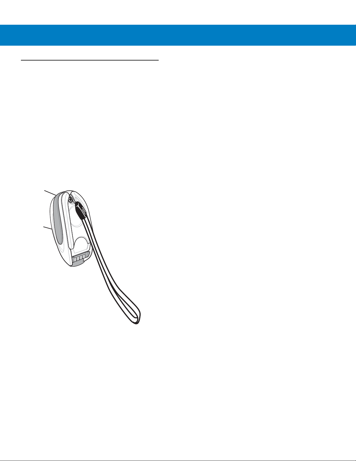
Lanyard for wearing the scanner on a wrist.
Lanyard
The lanyard attaches to the inside of the scanner battery door latch.
Getting Started 1 - 13
Figure 1-10
To attach the lanyard:
1. Open the battery door latch as described in Replacing the Scanner Battery on page 1-9. Do not remove the
battery.
Attached Lanyard
Page 32

1 - 14 LS4278 Product Reference Guide
Battery Door
Latch
Loop Guides
Screw Container
2. Hook the loop of the lanyard around the screw container inside the battery door latch, between the loop guides.
Figure 1-11
3. Close the battery door latch.
4. Tighten the screw.
Attaching Lanyard
Page 33

Chapter 2 Scanning
Introduction
This chapter provides beeper and LED definitions, scanning techniques, general instructions and tips about
scanning, and decode zone diagrams.
Beeper Definitions
The scanner issues different beep sequences and patterns to indicate status. Table 2-1 defines beep sequences
that occur during both normal scanning and while programming the scanner. (For additional beeper definitions, see
Wireless Beeper Definitions on page 4-3.
Table 2-1
Standard Use
Low/medium/high beeps Power up.
High beep A bar code symbol was decoded (if decode beeper is enabled).
Four long low beeps 1. A transmission error was detected in a scanned symbol. The
Five low long beeps Conversion or format error.
Low beep Scanner detects power when inserted into a cradle.
Standard Beeper Definitions
Beeper Sequence Indication
data is ignored. This occurs if a unit is not properly configured.
Check option setting.
2. When communicating with a cradle, the cradle acknowledges
receipt of data. If the acknowledgment is not received, this
transmission error beep sequence sounds. Data may still have
been received by the host. Check the host system for receipt of
transmitted data. If data was not received by the host, re-scan the
bar code.
Note: This feature is enabled by default and can be disabled (see
Beep on Insertion on page 5-5
).
Page 34

2 - 2 LS4278 Product Reference Guide
Table 2-1
Low/high/low/high beeps Out of memory - unable to store a new bar code.
Low/high/low beeps ADF transmit error.
High/high/high/low beeps RS-232 receive error.
Parameter Menu Scanning
Long low/long high beeps Input error, incorrect bar code or
High/low beeps Keyboard parameter selected. Enter value using bar code keypad.
High/low/high/low beeps Successful program exit with change in the parameter setting.
Long low/long high/long low/long high beeps Out of host parameter storage space. Scan
Wireless Operation
High/low/high/low beeps Pairing bar code scanned.
Low/high beeps Bluetooth connection established.
Standard Beeper Definitions (Continued)
Beeper Sequence Indication
incorrect bar code programming sequence; remain in program
mode.
page 5-3
.
Cancel
scanned, wrong entry,
Default Parameters on
High/low beeps Bluetooth disconnection event.
Note: When connected to a remote device using SPP or HID, if a
disconnect beep sequence sounds immediately after a bar code is
scanned, check the host device for receipt of transmitted data. It is
possible that an attempt was made to transmit the last bar code
scanned after the connection was lost.
Long low/long high beeps Page timeout; remote device is out of range/not powered.
Long low/long high/long low/long high beeps Connection attempt was rejected by remote device.
Code 39 Buffering
High/low beeps New Code 39 data was entered into the buffer.
Three long high beeps Code 39 buffer is full.
Low/high/low beeps The Code 39 buffer was erased or there was an attempt to clear or
transmit an empty buffer.
Low/high beeps A successful transmission of buffered data.
Host Specific
USB only
Four high beeps Scanner has not completed initialization. Wait several seconds and
scan again.
Scanner gives a power-up beep after
scanning a USB Device Type.
Communication with the bus must be established before the
scanner can operate at the highest power level.
Page 35

Scanning 2 - 3
Table 2-1
Standard Beeper Definitions (Continued)
This power-up beep occurs more than once. The USB bus may put the scanner in a state where power to the
RS-232 only
High beep A <BEL> character is received and Beep on <BEL> is enabled
LED Definitions
In addition to beeper sequences, the scanner communicates with the user using a two-color LED display. T able 2-2
defines LED colors that display during scanning.
Table 2-2
Scanning LED
Green Flash A bar code was successfully decoded.
Standard LED Definitions
Beeper Sequence Indication
scanner is cycled on and off more than once. This is normal and
usually happens when the host PC cold boots.
(Point-to-Point mode only).
LED Indication
Charging LED
1
Green - Slow Continuous Flash
Non-critical battery temperature fault. Battery is above or below normal
operating temperature.
If this occurs, do not use the scanner and move the scanner to a location within
normal operating temperature. The scanner can remain in the cradle while the
battery warms or cools to normal operating temperature.
Green - Fast Continuous Flash
Note: For appropriate charging temperatures, see
2
Scanner is charging.
Table 3-3 on page 3-8
.
Green - Solid Scanner is fully charged.
Amber - Continuous Flash Critical battery temperature fault. Battery is above or below normal operating
temperature.
If this occurs, do not use the scanner and move the scanner to a location within
normal operating temperature. The scanner can remain in the cradle while the
battery warms or cools to normal operating temperature.
Note: For appropriate charging temperatures, see
1
A slow continuous flash is estimated at 1 flash per second.
2
A fast continuous flash is estimated at 2 flashes per second.
Table 3-3 on page 3-8
.
Page 36

2 - 4 LS4278 Product Reference Guide
Single-Line Mode Multi-Line Raster Mode
012345
012345
Scanning in Hand-Held Mode
To program the scanner, see the appropriate host chapter, Chapter 4, Radio Communications and Chapter 13,
Symbologies. (In addition to the parameters included in the chapters mentioned, user preference and
miscellaneous scanner option parameters are also available in this guide.)
To s c an :
1. Aim the scanner at the bar code.
2. Press the trigger.
Figure 2-1
3. Upon successful decode, the scanner beeps and the LED turns green. (For more information about beeper
and LED definitions, see Table 2-1 and Table 2-2.)
Scanning in Hand-Held Mode
NOTE Scan line lengths vary depending on the scan line width selected (see Scan Line Width on page 5-10). A
full scan line width is the default. Medium and short scan line widths are useful for scanning menus or
pick-lists.
Aiming
On a typical UPC 100% hold the scanner between contact and 19 inches from the symbol (see Decode Zone on
page 2-9). When scanning using a single-line scan mode, ensure the scan line crosses every bar and space of the
symbol.
Figure 2-2
Acceptable and Incorrect Single-Line Aimin g
Page 37

Scanning 2 - 5
012345
65
o
65
o
When scanning using a multi-line scan mode, at least one scan line must cross every bar and space of the symbol.
012345
Figure 2-3
Acceptable and Incorrect Multi-Line Aimin g
Regardless of the scan mode, the scan line is smaller when the scanner is closer to the symbol and larger when it
is farther from the symbol. Scan symbols with smaller bars or elements (mil size) closer to the scanner, and those
with larger bars or elements (mil size) farther from the scanner.
Do not hold the scanner directly over the bar code. Laser light reflecting directly back into the scanner from the bar
code is known as specular reflection. This specular reflection can make decoding difficult.
NOTE Scan line lengths vary depending on the scan line width selected. A full scan line width is the default.
Medium and short scan line widths are useful for scanning menus or pick-lists.
For more information about scan line widths and scanning modes, see page 5-9 and page 5-10, respectively.
The scanner can be tilted up to 65° forward or back and achieve a successful decode (Figure 2-4). Simple practice
quickly shows what tolerances to work within.
Figure 2-4
Maximum Tilt Angles and Dead Zone
Page 38

2 - 6 LS4278 Product Reference Guide
Scanning in Hands-Free Mode
The optional Intellistand adds greater flexibility to scanning operation. When the scanner is seated in the stand’s
“cup,” the scanner’s built-in sensor places the scanner in hands-free mode. When the scanner is removed from the
stand, it automatically switches modes to operate in its normal hand-held triggered mode.
While in Intellistand, the scanner enters low power mode (Intellistand Idle Timeout) when no bar code is decoded
within 15 minutes. See Intellistand Idle Timeout on page 5-5 to set timeout intervals.
NOTE When the scanner enters Intellistand Idle Timeout (low power mode in the stand), scanning capability
suspends. To restart scanning capability, press the trigger or remove the scanner and replace it into the
stand.
Assemble the Stand
Figure 2-5
Assembling Intellistand
Page 39

Scanning 2 - 7
Scanner Holder
Height Adjustment Knob
Angle Adjustment Knob
Cup
Scanning with Intellistand
When the scanner is placed in Intellistand, the scan pattern selected in hand-held triggered mode continues (see
Scan Pattern on page 5-9).
NOTE When the scanner is configured as a Master or Cradle Host and the Bluetooth connection to the remote
device is lost, the scanner must be removed from Intellistand and re-paired to the remote device. To
accomplish this, pull the trigger which engages the auto-reconnect feature, or scan the pairing bar code
for the remote device.
CAUTION When the scanner is not used for an extended period of time, place it in the cradle for charging. This
prolongs battery life symbol indicates that if this information is ignored, the possiblity of data or
material damage may occur.
To operate the scanner in Intellistand:
1. Ensure the scanner is set up to communicate with the cradle, and the cradle is properly connected to the host
and (see the appropriate host chapter for information on host connections).
2. Insert the scanner in Intellistand by placing the front of the scanner into the stand’s “cup.”
Figure 2-6
3. Use the Intellistand’s adjustment knobs to adjust the height and angle of the scanner.
Inserting the Scanner in the Intellistand
Page 40

2 - 8 LS4278 Product Reference Guide
4. Present the bar code.
NOTE When the bar code is in view, the scanner emits a full scan line. After a decode, the scan line blinks.
5. Upon successful decode, the scanner beeps and the LED turns green. For more information about beeper and
LED definitions, see Table 2-1 and Table 2-2.
NOTE If no bar code is decoded after 15 minutes in the Intellistand, the scanner enters low power mode, or
Intellistand idle timeout. See Intellistand Idle Timeout on page 5-5 to set the Intellistand idle timeout
interval.
Page 41

Decode Zone
Note: Typical performance at 73° F (23° C) on
high quality symbols in normal room light.
LS 4278
*Minimum distance determined by symbol length and scan angle
Depth of Field
*
5 mil
5.5
10 mil
29
20 mil
1.5
13 mil
19
14.5
in.
cm
0
0
5
12.7
10
25.4
15
38.1
20
50.8
25
63.5
30
76.2
35
88.9
40
101.6
W
i
d
t
h
o
f
F
i
e
l
d
00
12.7
25.4
38.1
5
10
in. cm
15
12.75
25.410
15 38.1
Scanning 2 - 9
Figure 2-7
LS4278 Decode Zone
Page 42

2 - 10 LS4278 Product Reference Guide
Page 43

Chapter 3 Maintenance, Troubleshooting &
Technical Specifications
Introduction
This chapter provides suggested scanner and cradle maintenance, troubleshooting, technical specifications, and
signal descriptions (pinouts).
Maintenance
Scanner
Cleaning the exit window is the only maintenance required. A dirty window may affect scanning accuracy.
•
Do not allow any abrasive material to touch the window.
•
Remove any dirt particles with a damp cloth.
•
Wipe the window using a tissue moistened with ammonia/water.
Cradle
•
Do not spray water or other cleaning liquids directly into the window.
•
Do not pour, spray, or spill any liquid on the cradle.
Page 44

3 - 2 LS4278 Product Reference Guide
Battery Information
Zebra rechargeable battery packs are designed and constructed to the highest standards within the industry.
However, there are limitations to how long a battery can operate or be stored before needing replacement. Many
factors affect the life of a battery pack such as heat, cold, customer usage profiles, age and severe drops.
When batteries are stored over a year, battery cell manufacturers advise that some irreversible deterioration in
overall battery quality may occur. To minimize this loss, they recommend storing batteries half charged in a dry,
cool place between 41° F and 77° F (5° C and 25° C), the cooler the better, and removed from the equipment to
prevent the loss of capacity. Batteries should be charged to half capacity at least once a year. If an electrolyte
leakage is observed, avoid any contact with the affected area and properly dispose of the battery.
Replace the battery when a significant loss of run time is detected. Batteries must be charged within the 32° F to
104° F (0° C to 40°C) temperature range.
The standard warranty period for all Zebra batteries is 30 days, regardless if the battery was purchased separately
or included as part of the device.
Troubleshooting
Table 3-1
Battery
Scanner battery requires frequent
charging.
Beeper Indications
Scanner emits low/high/low beeps. ADF transmit error. See
Scanner emits a low/high/low/high
beep sequence while it is being
programmed.
Troubleshooting
Problem Possible Causes Possible Solutions
Battery may need reconditioning. Restore the battery by performing a
battery reconditioning cycle. See
Reconditioning the Scanner Battery
on page 1-10
Formatting
programming.
Invalid ADF rule is detected. See
Formatting
programming.
The Code 39 buffer was erased or
there was an attempt to clear or
transmit an empty buffer.
Out of ADF parameter storage
space.
Normal when scanning the Code 39
Buffering
upon attempt to transmit an empty
Code 39 buffer.
Erase all rules and re-program with
shorter rules.
for more information.
Chapter 14, Advanced Data
for information about ADF
Chapter 14, Advanced Data
for information about ADF
Clear Buffer
bar code or
Page 45

Maintenance, Troubleshooting & Technical Specifications 3 - 3
Table 3-1
Scanner emits long low/long high
beeps.
Scanner emits long low/long
high/long low/long high beeps.
Scanner emits high/high/high/low
beeps.
Scanner emits high/low beeps. The scanner is buffering Code 39
Troubleshooting (Continued)
Problem Possible Causes Possible Solutions
Input error, incorrect bar code or
Cancel
Page timeout; remote device is
out of range/not powered.
Out of host parameter storage
space.
Out of memory for ADF rules. Reduce the number of ADF rules or the
Connection attempt was rejected
by remote device.
RS-232 receive error. Normal during host reset. Otherwise,
data.
Or
Keyboard parameter selected.
bar code was scanned.
Scan the correct numeric bar codes
within range for the parameter
programmed.
Move the scanner back into range of
the remote device; try to re-connect;
check remote device configuration.
Scan
Default Parameters on page
5-3
.
number of steps in the ADF rules.
Free up remote device resources.
set the scanner's RS-232 parity to
match the host setting.
Normal.
Or
Enter value using bar code keypad.
Scanner emits three long high
beeps.
Scanner emits four high beeps on
trigger release.
Bluetooth disconnection event. Move the scanner back into range of
the remote device.
In Master (SPP) mode, re-pair the
scanner and cradle by scanning the
PAIR
bar code on the cradle; check
cradle power.
In Slave (SPP/HID) mode, reestablish
connection between the scanner and
remote device from the remote device
side.
Code 39 buffer is full. Scan the Code 39 bar code without a
leading space or scan
Code 39
stored Code 29 data.
Low battery. Place scanner in cradle to charge the
battery.
on
page 13-28
Do Not Buffer
to transmit
Page 46

3 - 4 LS4278 Product Reference Guide
Table 3-1
Scanner emits four long low beeps. A transmission error was
Scanner emits five low long beeps. Conversion or format error. Check ADF rules for the host.
Decoding Bar Codes
Scanner emits the laser, but does
not decode the bar code.
Troubleshooting (Continued)
Problem Possible Causes Possible Solutions
This occurs if a unit is not properly
detected in a scanned symbol.
The data is ignored.
The scanner is either:
- Out of range
- Not paired to the cradle
- Not connected to a remote
Bluetooth device.
Acknowledgment that transmitted
data was not received by the
cradle.
Scanner is not programmed for
the correct bar code type.
configured. Check option setting.
Move the scanner back into range of
the remote device.
Or
Scan the
Data may have been received by the
host. Check the host system for receipt
of transmitted data. If data was not
received by the host, re-scan the bar
code.
Program the scanner to read that type
of bar code. See
Symbologies
PAIR
bar code on the cradle.
Chapter 13,
.
Scanner decodes bar code, but does
not transmit the data to the host.
Bar code symbol is unreadable. Scan test symbols of the same bar
code type to determine if the bar code
is defaced.
Distance between scanner and
bar code is incorrect.
The scan line is not crossing
every bar and space of the
symbol.
Scanner is not programmed for
the correct host type.
Interface cable is loose. Ensure all cable connections are
Cradle is not programmed for the
correct host interface.
Scanner not paired to
host-connected interface.
Move the scanner closer to or further
from the bar code. See
on page 2-9
Move the symbol until the scan line is
within the acceptable aiming pattern.
See
Figure 2-2 on page 2-4
Scan the appropriate host type
programming bar code. See the
chapter corresponding to the host type.
secure.
Check scanner host parameters or edit
options.
Pair the scanner to the cradle by
scanning the
cradle.
.
PAIR
Decode Zone
.
bar code on the
Page 47

Maintenance, Troubleshooting & Technical Specifications 3 - 5
Table 3-1
Scanner emits five long low beep
after a bar code is decoded.
Troubleshooting (Continued)
Problem Possible Causes Possible Solutions
Cradle has lost connection to
host.
Conversion or format error was
detected.
The scanner’s conversion
parameters are not properly
configured.
Conversion or format error was
detected.
An ADF rule was set up with
characters that can't be sent for
the host selected.
Conversion or format error was
detected.
A bar code was scanned with
characters that can't be sent for
that host.
In this exact order: disconnect power
supply; disconnect host cable; wait
three seconds; reconnect host cable;
reconnect power supply; reestablish
pairing.
Ensure the scanner’s conversion
parameters are properly configured.
Change the ADF rule, or change to a
host that can support the ADF rule.
Change the bar code, or change to a
host that can support the bar code.
Host Displays
Host displays scanned data
incorrectly.
Scanner is not programmed to
work with the host.
Ensure the proper host is selected.
Scan the appropriate host type
programming bar code.
For RS-232, ensure the scanner’s
communication parameters match the
host’s settings.
For a USB HID keyboard or Keyboard
Wedge configuration, ensure the
system is programmed for the correct
keyboard type and language, and turn
off the CAPS LOCK key.
Ensure editing options (e.g., ADF,
UPC-E to UPC-A Conversion) are
properly programmed.
Check the scanner’s host type
parameters or editing options.
Page 48

3 - 6 LS4278 Product Reference Guide
Table 3-1
Troubleshooting (Continued)
Problem Possible Causes Possible Solutions
Trigger
Nothing happens when the trigger is
pulled.
The laser does not appear when the
trigger is pulled.
No power to the scanner. Check the system power. If the
configuration requires a power supply,
re-connect the power supply.
Check the battery. Ensure that end cap
to battery chamber is secured.
Interface/power cables are loose. Check for loose cable connections and
re-connect cables.
Scanner is disabled. For Synapse or IBM-468x mode,
enable the scanner via the host
interface.
No power to the scanner. Check the system power. If the
configuration requires a power supply,
re-connect the power supply.
Incorrect host interface cable is
used.
Verify that the correct host interface
cable is used. If not, connect the
correct host interface cable.
Interface/power cables are loose. Check for loose cable connections and
re-connect cables.
NOTE If after performing these checks the symbol still does not scan, contact the distributor or contact Zebra
Support. See page xv for contact information.
Page 49

Technical Specifications
Maintenance, Troubleshooting & Technical Specifications 3 - 7
Table 3-2
Physical Characteristics
Dimensions 7.3 in. H x 3.85 in. L x 2.7 in. W
Weight (with battery) Approximately 8.4 oz. (238 g)
Color Cash Register White or Twilight Black
Performance Characteristics
Light Source (Laser) 650nm laser diode
Scan Element Frequency 50Hz
Decode Rate 200 decodes per second
Radio Range Minimum 33 ft (10m) / Typical warehouse environment 50 ft. (15m)
Battery Specifications 720maH NiMH - (3) AAA
Technical Specifications - LS4278 Scanner
Item Description
(18.5 cm H x 9.7 cm L x 6.9 cm W)
number of scans per full charge: 32,000+ @ 1 scan/second
Charge Time:
Fully discharged battery: < 3 hours via external power / approximately 4.5
hours via host power through cable
Note: Typical daily scans are less than 4,000, which fully charges within 1
hour
Roll Tolerance ± 35°
Pitch Tolerance ± 60°
Yaw Tolerance ± 60°
Nominal Working Distance 5 mil (Code 39): 1.5 to 5.5 in. (3.81 to 13.97 cm)
13 mil (100% UPC/EAN): 0 to 19 in. (0 to 48.25 cm)
10 mil (Code 39): 0 to 14 in. (0 to 35.56 cm)
20 mil (Code 39): 0 to 29 in. (0 to 73.66 cm)
(See
Decode Zone on page 2-9
Print Contrast Minimum 25% minimum reflectance
Multi-Line Aiming Coverage At 5 in. reading distance: ~ 0.5 in. (1.3 cm)
At 10 in. reading distance: ~ 1 in. (2.5 cm)
Motion Tolerances Horizontal Velocity: 200 in. (508 cm) / sec
Vertical Velocity: 200 in. (508 cm) / sec
Angular Velocity: 200 in. (508 cm) / sec
)
Page 50

3 - 8 LS4278 Product Reference Guide
Table 3-2
Decode Capability UPC/EAN and with supplementals, Code 39, Code 39 Full ASCII, Tri-optic
Interfaces Supported See
User Environment
Operating Temperature 32° to 122° F (0° to 50° C)
Storage Temperature -40° to 158° F (-40° to 70° C)
Humidity 5% to 95%, non-condensing
Drop Specifications Withstands multiple 5 ft./1.5 m drops to concrete
# of Cradle Insertions 250,000+ insertions
Ambient Light Tolerance Tolerant to typical artificial indoor and natural outdoor (direct sunlight) lighting
Accessories
Technical Specifications - LS4278 Scanner (Continued)
Item Description
Code 39, GS1 DataBar Variants, GS1-128, Code 128, Code 128 Full ASCII,
Code 93, Codabar (NW1), Interleaved 2 of 5, Discrete 2 of 5 MSI, Codell,
IATA, Bookland EAN, Code 32
Table 3-3
conditions. Fluorescent, Incandescent, Mercury Vapor, Sodium Vapor, LED:
450 Ft Candles (4,844 Lux) Sunlight: 8000 Ft Candles (86,111 Lux)
Note: LED lighting with high AC ripple content can impact scanning
performance.
.
Mounting Options Intellistand with adjustable height:
5-10 in. (12.7 cm -25.4 cm)
Adjustable angle:
0º - 90º
A desktop / wall-mount bracket is also available.
Lanyard Lanyard attaches to the battery door.
Table 3-3
Physical Characteristics
Dimensions: 2.0 in. H x 8.35 in. L x 3.4 in. W
Weight Approximately 6.4 oz. (183 gm)
Voltage & Current Charging Cradle:
Technical Specifications - STB4208/4278 Cradle
Item Description
(5 cm H x 21.1 cm L x 8.6 cm W)
Voltage Current
5 +/-10% VDC 620 mA (External power)
5 +/-10% VDC 450 mA (Host power through cable)
12 +/-10% VDC 270 mA (External power)
12 +/-10% VDC 230 mA (Host power through cable)
Non-charging Cradle: 5V @ 70ma or 12 V @ 50 mA
Color Cash Register White or Twilight Black
Page 51

Maintenance, Troubleshooting & Technical Specifications 3 - 9
Table 3-3
Power Requirements 4.75 - 14.0 VDC
Performance Characteristics
Interfaces Supported Features on-board Multiple Interface with: RS-232C (Standard, Nixdorf, ICL, & Fujitsu);
User Environment
Operating Temperature 32° to 122° F (0° to 50° C)
Storage Temperature -40° to 158° F (-40° to 70° C)
Charging Temperature 32° to 104° F (0° to 40° C) nominal, 41° to 95° F (5° to 35° C) ideal
Humidity 5% to 95% (non-condensing)
Regulatory
Electrical Safety UL1950, CSA C22.2 No. 950,
Technical Specifications - STB4208/4278 Cradle (Continued)
Item Description
IBM 468x/469x; Keyboard Wedge; USB (Standard, IBM SurePOS, Macintosh);
Laser/Wand Emulation; 123Scan; Remote Scanner Management.
In addition, Synapse Adaptive Connectivity allows for connectivity to all of the above plus
many non-standard interfaces.
EN60950/IEC950
EMI/RFI FCC Part 15 Class B, ICES-003 Class B, European Union EMC Directive, Australian
SMA
Radio Bluetooth, Class 2, Version 1.2, Serial Port & HID Profiles
2.402 to 2.480 GHz Adaptive Frequency Hopping (co-existence with 802.11 wireless
networks)
Data rate: 720 kbps
Accessories
Mounting Options Desktop / wall-mount bracket is available
Power Supplies Power supplies are available for applications that do not supply power over host cable.
Page 52

3 - 10 LS4278 Product Reference Guide
Pin 1
Pin 4 Pin 3 Pin 2
Cradle Signal Descriptions
The signal descriptions in Table 3-4 apply to the connector on the scanner and are for reference only.
Table 3-4
1 Reserved SynClock Reserved Reserved Reserved Jump to Pin 6
2 Power Power Power Power Power Power
3 Ground Ground Ground Ground Ground Ground
4 IBM_A(+) Reserved TxD KeyClock DBP Reserved
5 Reserved Reserved RxD TermData CTS D +
6 IBM_B(-) SynData RTS KeyData RTS Jump to Pin 1
7 Reserved Reserved CTS TermClock Reserved D -
8 Reserved Reserved Reserved Reserved Reserved Reserved
9 N/A N/A N/A N/A N/A N/A
10 N/A N/A N/A N/A N/A N/A
Figure 3-1 illustrates the positions of the cradle pins.
Cradle Signal Pin-outs
Pin IBM Synapse RS-232
Keyboard
Wedge
Wand USB
Figure 3-1
The signal descriptions in Table 3-5 apply to the connector from the scanner to the scanner cradle and are for
reference only.
Table 3-5
1CRADLE_TXD
2VCC
3GND
4 CRADLE_RXD
Cradle Pin Assignments
Cradle Pin-outs
Pin Description
Page 53

Chapter 4 Radio Communications
*Disable Pair on Contacts
Feature/Option
* Indicates Default
Introduction
This chapter provides information about the modes of operation and features available for wireless communication
between scanners, cradles and hosts. The chapter also includes the parameters necessary to configure the
scanner.
The scanner ships with the settings shown in the Radio Communication Default Table on page 4-2 (also see
Appendix A, Standard Default Parameters for all host device and miscellaneous scanner defaults). If the default
values suit requirements, programming is not necessary.
To set feature values, scan a single bar code or a short bar code sequence. The settings are stored in non-volatile
memory and are preserved even when the scanner is powered down.
If not using a Synapse or USB cable with the cradle, select a host type (see each host chapter for specific host
information) after the power-up beeps sound. This is only necessary upon the first power-up when connected to a
new host.
To return all features to default values, scan a default bar code in Default Parameters on page 5-3. Throughout the
programming bar code menus, default values are indicated with asterisks (
*).
Scanning Sequence Examples
In most cases, scan one bar code to set a specific parameter value.
Errors While Scanning
Unless otherwise specified, to correct an error during a scanning sequence, just re-scan the correct parameter.
Page 54

4 - 2 LS4278 Product Reference Guide
Radio Communications Parameter Defaults
Table 4-1 lists the defaults for radio communication parameters. If you wish to change any option, scan the
appropriate bar code(s) provided in the Radio Communications Parameters section beginning on page 4-4.
NOTE See Appendix A, Standard Default Parameters for all user preferences, hosts, symbologies, and
miscellaneous default parameters.
Table 4-1
Bluetooth Host (Host Type) Cradle Host
Discoverable Mode General
Country Keyboard Types (Country Code) North American
HID Keyboard Keystroke Delay No Delay (0 msec)
CAPS Lock Override Disable
Ignore Unknown Characters Enable
Emulate Keypad Disable
Keyboard FN1 Substitution Disable
Function Key Mapping Disable
Simulated Caps Lock Disable
Convert Case No Case Conversion
Beep on Reconnect Attempt Disable
Reconnect Attempt Interval 30 sec
Radio Communication Default Table
Parameter Default
Page
Number
4-4
4-7
4-8
4-10
4-10
4-11
4-11
4-12
4-12
4-13
4-13
4-14
4-15
Auto-reconnect in Bluetooth Keyboard
Emulation (HID Slave) Mode
Modes of Operation
(Point-to-Point/Multipoint-to-Point
Parameter Broadcast (Cradle Host Only) Enable
Pairing Modes Unlocked
Pairing on Contacts Disable
Connection Maintenance Interval 15 min
Authentication Disable
Variable Pin Code Static
Encryption Disable
On Bar Code Data
Point-to-Point
4-17
4-18
4-19
4-20
4-21
4-23
4-25
4-26
4-27
Page 55

Wireless Beeper Definitions
When the scanner scans the pairing bar code it issues various beep sequences indicating successful or
unsuccessful operations. Table 4-2 defines beep sequences that occur during pairing operations. (For additional
beeper definitions, see Beeper Definitions on page 2-1.).
Radio Communications 4 - 3
Table 4-2
Four long low beeps 1. A transmission error was detected in a scanned symbol. The data is ignored.
Five high beeps Emitted every 5 seconds while a reconnection attempt is in progress. (See
High/low/high/low beeps Pairing bar code scanned.
Low/high beeps Bluetooth connection established.
High/low beeps Bluetooth disconnection event.
Long low/long high beeps Page timeout; remote device is out of range/not powered. (See
Wireless Beeper Definitions
Beeper Sequence Indication
This occurs if a unit is not properly configured. Check option setting.
2. When communicating with a cradle, the cradle acknowledges receipt of data. If
the acknowledgment is not received, this transmission error beep sequence
sounds. Data may still have been received by the host. Check the host system for
receipt of transmitted data. If data was not received by the host, re-scan the bar
code.
Auto-reconnect Feature on page 4-14
Note: When connected to a remote device using SPP or HID, if a disconnect beep
sequence sounds immediately after a bar code is scanned, check the host device
for receipt of transmitted data. It is possible that an attempt was made to transmit
the last bar code scanned after the connection was lost.
Feature on page 4-14
.)
.)
Auto-reconnect
Long low/long high/long low/
long high beeps
Connection attempt was rejected by remote device.
Note: In the case of
connected to another scanner in single Point-to-Point locked mode, or the piconet
may be full in Multipoint-to-Point mode. If Pair On Contacts is enabled and the
scanner that is inserted is already connected to the cradle, no beeping occurs.
Pairing Methods on page 4-21
, the cradle may already be
Page 56

4 - 4 LS4278 Product Reference Guide
Radio Communications Host Types
To set up the scanner for communication with a cradle, or to use standard Bluetooth profiles, scan the appropriate
host type bar code below.
•
Cradle Host (default) - Select this host type for scanner(s) to cradle operation. The scanner must then be
paired to the cradle and the cradle communicates directly to the host via the host interface cable connection.
•
Serial Port Profile (Master) - Select this host type for Bluetooth Technology Profile Support (see page 4-6).
The scanner connects to the PC/host via Bluetooth and performs like there’s a serial connection. The
scanner initiates the connection to the remote device and is the Master. Scan Serial Port Profile (Master),
then scan the PAIR bar code for the remote device. See Pairing Bar Code Format on page 4-22 for
information about creating a pairing bar code for a remote device.
•
Serial Port Profile (Slave) - Select this host type for Bluetooth Technology Profile Support (see page 4-6). The
scanner connects to the PC/host via Bluetooth and performs like there’s a serial connection. The scanner
accepts incoming connection requested from a remote device and is the Slave. Scan Serial Port Profile
(Slave) and wait for the incoming connection.
•
Bluetooth Keyboard Emulation (HID Slave) - Select this host type for Bluetooth Technology Profile Support.
(See page 4-6 for Bluetooth Technology Profile Support and Master/Slave definitions.) The scanner connects
to the PC/host via Bluetooth and performs like a keyboard. The scanner accepts incoming connection
requested from a remote device and is the slave. Scan Bluetooth Keyboard Emulation (HID Slave) and
wait for the incoming connection.
NOTE 1.The scanner supports keyboard emulation over the Bluetooth HID profile. For detailed information, and
HID host parameters, see HID Host Parameters on page 4-8.
2. When the scanner is paired to the cradle in SPP Master or Cradle Host mode, the scanner
automatically tries to reconnect to a remote device when a disconnection occurs that is due to the radio
losing communication. For more information see Auto-reconnect Feature on page 4-14.
Page 57

Radio Communications Host Types (continued)
*Cradle Host
Radio Communications 4 - 5
Serial Port Profile (Master)
Serial Port Profile (Slave)
Bluetooth Keyboard Emulation (HID Slave)
Page 58

4 - 6 LS4278 Product Reference Guide
Bluetooth Technology Profile Support
With Bluetooth Technology Profile Support, the cradle is not required for wireless communication. The scanner
communicates directly to the host using Bluetooth technology. The scanner supports the standard Bluetooth Serial
Port Profile (SPP) and HID Profiles which enable the scanner to communicate with other Bluetooth devices that
support these profiles.
•
SPP - the scanner connects to the PC/host via Bluetooth and performs like there’s a serial connection.
•
HID - the scanner connects to the PC/host via Bluetooth and performs like a keyboard.
Master/Slave Set Up
The scanner can be set up as a Master or Slave.
When the scanner is set up as a Slave, it is discoverable and connectable to other devices. When the scanner is
set up as a Master, the Bluetooth address of the remote device to which a connection is requested is required. A
pairing bar code with the remote device address must be created and scanned to attempt a connection to the
remote device. See the Pairing Bar Code Format on page 4-22 for information about creating a pairing bar code.
Master
When the scanner is set up as a Master (SPP), it initiates the radio connection to a slave device. Initiating the
connection is done by scanning a pairing bar code for the remote device (see Pairing Bar Code Format on page
4-22).
Slave
When the scanner is set up as a Slave device (SPP), the scanner accepts an incoming connection request from a
remote device.
NOTE The number of scanners is dependent on the host’s capability.
Page 59

Radio Communications 4 - 7
Bluetooth Friendly Name
You can set a meaningful name for the scanner that appears in the application during device discovery. The default
name is the scanner name followed by its serial number, e.g.,
reverts the scanner to this name; use custom defaults to maintain the user-programmed name through a Set
Defaults operation.
To set a new Bluetooth Friendly Name, scan the following bar code, then scan up to 23 characters from Appendix
E, Alphanumeric Bar Codes. If the name contains less than 23 characters, scan End of Message on page E-7 after
entering the name.
NOTE If your application allows you to set a device name, this takes precedence over the Bluetooth Friendly
Name.
LS4278 123456789ABCDEF. Scanning Set Defaults
Bluetooth Friendly Name
Discoverable Mode
Select a discoverable mode based on the device initiating discovery:
•
Select General Discoverable Mode when initiating connection from a PC.
•
Select Limited Discoverable Mode when initiating connection from a mobile device (e.g., Zebra Q), and the
device does not appear in General Discoverable Mode. Note that it can take longer to discover the device in
this mode.
The device remains in Limited Discoverable Mode for 30 seconds, and green LEDs flash while in this mode.
It is then non-discoverable. To re-active Limited Discoverable Mode, press the trigger.
*General Discoverable Mode
Limited Discoverable Mode
Page 60

4 - 8 LS4278 Product Reference Guide
HID Host Parameters
The scanner supports keyboard emulation over the Bluetooth HID profile. In this mode the scanner can interact
with Bluetooth enabled hosts supporting the HID profile as a Bluetooth keyboard. Scanned data is transmitted to
the host as keystrokes.
Following are the keyboard parameters supported by the HID host.
HID Country Keyboard Types (Country Codes)
Scan the bar code corresponding to the keyboard type.
*North American Standard Keyboards
German Windows
Spanish Windows
French Windows
French Canadian Windows 98
Italian Windows
Page 61

HID Country Keyboard Types (Country Codes - continued)
Swedish Windows
Radio Communications 4 - 9
UK English Windows
Japanese Windows
Portuguese/Brazilian Windows
French Canadian Windows 2000/XP
Page 62

4 - 10 LS4278 Product Reference Guide
HID Keyboard Keystroke Delay
This parameter sets the delay, in milliseconds, between emulated keystrokes. Scan a bar code below to increase
the delay when the HID host requires a slower transmission of data.
*No Delay (0 msec)
Medium Delay (20 msec)
Long Delay (40 msec)
HID CAPS Lock Override
When enabled, the case of the data is preserved regardless of the state of the caps lock key. This setting is always
enabled for the “Japanese, Windows (ASCII)” keyboard type and can not be disabled.
*Do Not Override Caps Lock Key
(Disable)
Override Caps Lock Key
(Enable)
Page 63

Radio Communications 4 - 11
HID Ignore Unknown Characters
Unknown characters are characters the host does not recognize. When Send Bar Codes With Unknown
Characters is scanned, all bar code data is sent except for unknown characters, and no error beeps sound. When
Do Not Send Bar Codes With Unknown Characters is scanned, bar codes containing at least one unknown
character are not sent to the host, and an error beep sounds.
*Send Bar Codes With Unknown Characters
(Enable)
Do Not Send Bar Codes With Unknown Characters
(Disable)
Emulate Keypad
When enabled, all characters are sent as ASCII sequences over the numeric keypad. For example, ASCII A is sent
as "ALT make" 0 6 5 "ALT Break."
*Disable Keypad Emulation
Enable Keypad Emulation
Page 64

4 - 12 LS4278 Product Reference Guide
HID Keyboard FN1 Substitution
When enabled, this parameter allows replacement of any FN1 character in an EAN128 bar code with a Key
Category and value chosen by the user. See FN1 Substitution Values on page 5-15 to set the Key Category and
Key Value.
*Disable Keyboard FN1 Substitution
Enable Keyboard FN1 Substitution
HID Function Key Mapping
ASCII values under 32 are normally sent as control-key sequences. When this parameter is enabled, the keys in
bold are sent in place of the standard key mapping (see Table 8-2 on page 8-120. Table entries that do not have a
bold entry remain the same whether or not this parameter is enabled.
*Disable Function Key Mapping
Enable Function Key Mapping
Page 65

Radio Communications 4 - 13
Simulated Caps Lock
When enabled, the scanner inverts upper and lower case characters on the scanner bar code as if the Caps Lock
state is enabled on the keyboard. This inversion is done regardless of the current state of the keyboard Caps Lock
state.
*Disable Simulated Caps Lock
Enable Simulated Caps Lock
Convert Case
When enabled, the scanner converts all bar code data to the selected case.
*No Case Conversion
Convert All to LowerCase
Convert All to Upper Case
Page 66

4 - 14 LS4278 Product Reference Guide
Auto-reconnect Feature
When in SPP Master or Cradle Host mode, the scanner automatically tries to reconnect to a remote device when a
disconnection occurs that is due to the radio losing communication. This can happen if the scanner goes out of
range with the remote device, or if the remote device powers down. The scanner tries to reconnect for the period of
time specified by the Reconnect Attempt Interval setting. During that time the green LED continues to blink.
If the auto-reconnect process fails due to page time-outs, the scanner sounds a page timeout beep (long low/long
high) and enters low power mode. The auto-reconnect process can be re-started by pulling the scanner trigger.
If the auto-reconnect process fails because the remote device rejects the connection attempt, the scanner sounds
a connection reject beep sequence (see Wi reless Beeper Definitions on page 4-3) and deletes the remote pairing
address. If this happens, a pairing bar code must be scanned to attempt a new connection to the remote device.
NOTE If a bar code is scanned while the auto-reconnect sequence is in process, a transmission error beep
sequence sounds and the data is not transmitted to the host. After a connection is reestablished, normal
scanning operation returns. For error beep sequence definitions, see Beeper De finitions on page 2-1.
The scanner has memory available for storing a remote Bluetooth address for each Master mode (SPP, Cradle).
When switching between these modes, the scanner automatically tries to reconnect to the last device it was
connected to in that mode.
NOTE Switching between Bluetooth host types by scanning a host type bar code (page 4-4) causes the radio to
be reset. Scanning is disabled during this time. It takes several seconds for the scanner to re-initialize the
radio at which time scanning is enabled.
Reconnect Attempt Beep Feedback
When a scanner disconnects as it goes out of range, it immediately attempts to reconnect. While the scanner
attempts to reconnect, the green LED continues to blink. If the auto-reconnect process fails, the scanner emits a
page timeout beep (long low/long high) and stops blinking the LED. The process can be restarted by pulling the
trigger.
The Beep on Reconnect Attempt feature is disabled by default. When enabled, the scanner emits 5 short high
beeps every 5 seconds while the reconnection attempt is in progress.
Scan a bar code below to enable or disable Beep on Reconnect Attempt.
*Disable Beep on Reconnect Attempt
Enable Beep on Reconnect Attempt
Page 67

Radio Communications 4 - 15
Reconnect Attempt Interval
When a scanner disconnects as it goes out of range, it immediately attempts to reconnect for the default time
interval of 30 seconds. This time interval can be changed to one of the following options:
•
30 seconds
•
1 minute
•
5 minutes
•
30 minutes
•
1 hour
•
Indefinitely.
To set the Reconnect Attempt Interval, scan one of the bar codes below
*Attempt to Reconnect for 30 Seconds
Attempt to Reconnect for 5 Minutes
Attempt to Reconnect for 1 Minute
Page 68

4 - 16 LS4278 Product Reference Guide
Reconnect Attempt Interval (continued)
Attempt to Reconnect for 1 Hour
Attempt to Reconnect for 30 Minutes
Attempt to Reconnect Indefinitely
Page 69

Radio Communications 4 - 17
Auto-reconnect in Bluetooth Keyboard Emulation (HID Slave) Mode
In Bluetooth Keyboard Emulation (HID Slave) mode, select a re-connect option for when the scanner loses its
connection with a remote device:
•
Auto-reconnect on Bar Code Data: The scanner auto-reconnects when you scan a bar code. With this
option, a delay can occur when transmitting the first characters. The scanner sounds a decode beep upon
bar code scan, followed by a connection, a page timeout, a rejection beep, or a transmission error beep.
Select this option to optimize battery life on the scanner and mobile device. Note that auto-reconnect does
not occur on rejection and cable unplug commands.
•
Auto-reconnect Immediately: When the scanner loses connection, it attempts to reconnect. If a page
timeout occurs, the scanner attempts reconnect on a trigger pull. Select this option if the scanner’s battery life
is not an issue and you do not want a delay to occur when the first bar code is transmitted. Note that
auto-reconnect does not occur on rejection and cable unplug commands.
•
Disable Auto-reconnect: When the scanner loses connection, you must re-establish it manually.
*Auto-reconnect on Bar Code Data
Disable Auto-reconnect
Out of Range Indicator
An out of range indicator can be set by scanning Enable Beep on Reconnect Attempt on page 4-14 and extending
the time using the Reconnect Attempt Interval on page 4-15.
For example, with Beep on Reconnect Attempt disabled while the scanner loses radio connection when it is taken
out of range, the scanner attempts to reconnect silently during the time interval set by scanning a Reconnect
Attempt Interval.
Auto-reconnect Immediately
When Beep on Reconnect Attempt is enabled, the scanner emits 5 high beeps every 5 seconds while the
reconnection attempt is in progress. If the Reconnect Attempt Interval is adjusted to a longer period of time, such
as 30 minutes, the scanner emits 5 high beeps every 5 seconds for 30 minutes providing an out of range indicator.
Page 70

4 - 18 LS4278 Product Reference Guide
Scanner(s) To Cradle Support
Modes of Operation
The charging cradle with radio supports two radio communication modes of operation, allowing the scanner to
communicate wirelessly:
•
Point-to-Point
•
Multipoint-to-Point.
Point-to-Point Communication
In Point-to-Point communication mode, the cradle allows one scanner to connect to it at a time. In this mode, the
scanner is paired to the cradle either by insertion into the cradle (if pairing on contacts is enabled, page 4-21), or by
scanning the PAI R bar code on the cradle. Communication can be locked, unlocked (default), or in a lock override
state (see Pairing Modes on page 4-20). In locked mode, locking intervals must be set by scanning a connection
maintenance interval bar code beginning on page 4-23.
To activate this mode of operation, scan Point-to-Point.
Multipoint-to-Point Communication
In Multipoint-to-Point communication mode, up to three scanners can be paired to one cradle.
NOTE To connect multiple LS4278 scanners to a single CR0078-P base using multipoint-to-point mode, consult
your Zebra channel partner.
To activate this mode, the first scanner connected to the cradle must scan the Multipoint-to-Point bar code. This
mode allows a parameter broadcast (page 4-19) feature that forwards parameter bar code settings to all connected
scanners. In this mode, programming one scanner applies the settings to all connected scanners.
To select Point-to-Point or Multipoint-to-Point mode, scan the appropriate bar code.
Multipoint-to-Point Mode
*Point-to-Point Mode
Page 71

Radio Communications 4 - 19
Parameter Broadcast (Cradle Host Only)
When in multipoint-to-point mode, enable Parameter Broadcast to broadcast all parameter bar codes scanned to
all other scanners in the piconet. If disabled, parameter bar codes are processed by the individual scanner only,
and the scanner ignores parameters broadcast from other scanners or from the cradle.
*Enable Parameter Broadcast
Disable Parameter Broadcast
Pairing
Pairing is the process by which a scanner initiates communication with a cradle. Scanning Multipoint-to-Point
activates multi scanner-to-cradle operation and allows up to three scanners to pair to one cradle. The cradle
includes a pairing bar code.
To pair the scanner with the cradle, scan the pairing bar code on the cradle. A high/low/high/low beep sequence
indicates that the pairing bar code was decoded. When a connection between the cradle and scanner is
established, a low/high beep sounds.
NOTE 1. The pairing bar code that connects the scanner to a cradle is unique to each cradle.
2. Do not scan data or parameters until pairing completes.
3. When the scanner is paired to the cradle in SPP Master or Cradle Host mode, the scanner
automatically tries to reconnect to a remote device when a disconnection occurs that is due to the radio
losing communication. For more information see Auto-reconnect Feature on page 4-14.
Page 72

4 - 20 LS4278 Product Reference Guide
Pairing Modes
When operating with the cradle, two modes of pairing are supported:
•
Locked Pairing Mode - When a cradle is paired (connected) to the scanner (or to three scanners in
Multipoint-to-Point mode), any attempt to connect a different scanner, by either scanning the PAI R bar code
on the cradle or by inserting it into the cradle with the pairing on contacts feature enabled (page 4-21), is
rejected. The currently connected scanner(s) maintain connection. In this mode, you must set a Connection
Maintenance Interval on page 4-23.
•
Unlocked Pairing Mode - Pair (connect) a new scanner to a cradle at any time by either scanning the PA I R
bar code on the cradle or by inserting it into the cradle with the pairing on contacts feature enabled. This
unpairs the previous scanner from the cradle (Point-to-Point mode only).
NOTE In Multipoint-to-Point mode, pairing a fourth scanner while in Unlocked Pairing Mode replaces any
disconnected (out of range) scanner. However, if three scanners are actively connected to the cradle, a
fourth scanner cannot connect unless you first disconnect one of the original scanners by scanning the
Unpair bar code.
To set the cradle pairing mode, scan the appropriate bar code below.
*Unlocked Pairing Mode
Locked Pairing Mode
Lock Override
Lock Override overrides a locked scanner base pairing and connects a new scanner. In Multipoint-to-Point mode,
this unpairs any disconnected (out of range) scanner first, in order to connect the new scanner.
To use Lock Override, scan the bar code below, followed by the pairing bar code on the cradle.
LockOverride
Page 73

Radio Communications 4 - 21
Pairing Methods
There are two pairing methods. The default method allows the scanner and cradle to pair (connect) when the
pairing bar code on the cradle is scanned. A second method pairs the scanner and cradle when the scanner is
inserted in the cradle. To enable this feature, scan Enable Pair On Contacts below. With this feature enabled it is
not necessary to scan the pairing bar code on the cradle. If the pairing is successful, a low/high connection beep
sequence sounds a few seconds after the scanner is placed in the cradle. See Wireless Beeper Definitions on
page 4-3 for other beep sequences.
To enable or disable pairing on contacts, scan the appropriate bar code below.
Enable Pair On Contacts
*Disable Pair on Contacts
Unpairing
Unpair the scanner from the cradle or PC/host to make the cradle available for pairing with another scanner. Scan
the bar code below to disconnect the scanner from its cradle/PC host.
An unpairing bar code is also included in the LS4278 Quick Reference Guide.
Unpairing
Page 74

4 - 22 LS4278 Product Reference Guide
Paring Bar Code Content:
‘B’ + Bluetooth Address
B112233445566
Pairing Bar Code Format
When the scanner is configured as an SPP Master, you must create a pairing bar code for the remote Bluetooth
device to which the scanner can connect. The Bluetooth address of the remote device must be known. Pairing bar
codes are Code 128 bar codes and are formatted as follows:
<Fnc 3>Bxxxxxxxxxxxx
where:
•
B (or LNKB) is the prefix
•
xxxxxxxxxxxx represents the 12-character Bluetooth address.
Pairing Bar Code Example
If the remote device to which the scanner can connect has a Bluetooth address of 11:22:33:44:55:66, then the
pairing bar code is:
Page 75

Radio Communications 4 - 23
Connection Maintenance Interval
NOTE The Connection Maintenance Interval only applies in locked pairing mode (see page 4-20).
When a scanner disconnects from a cradle due to a Link Supervision Timeout, the scanner immediately attempts
to reconnect to the cradle for 30 seconds. If the auto-reconnect process fails, it can be restarted by pulling the
scanner trigger.
To guarantee that a disconnected scanner can reconnect when it comes back in range, the cradle reserves the
connection for that scanner for a period of time defined by the Connection Maintenance Interval. If the cradle is
supporting the maximum three scanners and one scanner disconnects, a fourth scanner cannot pair to the cradle
during this interval. To connect another scanner: either wait until the connection maintenance interval expires then
scan the PAIR bar code on the cradle with the new scanner; or, scan Lock Override (page 4-20) with the new
scanner then scan the PAIR bar code on the cradle.
NOTE When the cradle supports the maximum three scanners, it stores the remote pairing address of each
scanner in memory regardless of the scanner condition (e.g., discharged battery). When you want to
change the scanners paired to the cradle, unpair each scanner currently connected to the cradle by
scanning the Unpairing bar code prior and reconnect each appropriate scanner by scanning the PAIR bar
code on the cradle.
Connection Maintenance Interval options are:
•
15 minutes
•
30 minutes
•
One hour
•
Two hours
•
Four hours
•
Eight hours
•
24 hours
•
Indefinitely.
Considerations
The system administrator determines the Connection Maintenance Interval. A shorter interval allows new users to
gain access to abandoned connections more quickly, but causes problems if users leave the work area for
extended periods. A longer interval allows existing users to leave the work area for longer periods of time, but ties
up the system for new users.
To avoid this conflict, users who are going off-shift can scan the unpair bar code on page 4-21 to ignore the
Connection Maintenance Interval and make the connection immediately available.
Page 76

4 - 24 LS4278 Product Reference Guide
To set the Connection Maintenance Interval, scan one of the bar codes below
*Set Interval to 15 Minutes
Set Interval to 30 Minutes
Set Interval to 60 Minutes
Set Interval to 4 Hours
Set Interval to 2 Hours
Set Interval to 8 Hours
Set Interval to 24 Hours
Set Interval to Forever
Page 77

Bluetooth Security
The scanner supports Bluetooth Authentication and Encryption. Authentication can be requested by either the
remote device or the scanner. When Authentication is requested, the scanner uses its programmed PIN code to
generate a link key. Once Authentication is complete, either device may then negotiate to enable Encryption.
NOTE A remote device can still request Authentication.
Authentication
To force Authentication with a remote device (including the cradle), scan the Enable Authentication bar code
below. To prevent the scanner from forcing Authentication, scan the Disable Authentication bar code below.
Radio Communications 4 - 25
Enable Authentication
*Disable Authentication
Page 78

4 - 26 LS4278 Product Reference Guide
PIN Code
To set the PIN code (e.g., password) on the scanner, scan the bar code below followed by five alphanumeric
programming bar codes (see Appendix E, Alphanumeric Bar Codes. The default PIN code is 12345.
If the scanner communicates with a cradle with security enabled, synchronize the PIN codes on the scanner and
cradle. To achieve this, connect the scanner to the cradle when setting the PIN codes. If the scanner is not
connected to a cradle, the PIN code change only takes affect on the scanner. If security is required between the
scanner and cradle, and the PIN codes do not match, pairing fails. If the PIN codes are not synchronized,
re-synchronize them by disabling security, establishing a connection to the cradle, and then programming a new
PIN code.
Set PIN Code
Variable PIN Code
The default PIN code is the user-programmed Static PIN Code. Typically, however, HID connections require
entering a Variable PIN Code. If, when attempting connection, the application presents a text box that includes a
PIN, scan the Variable PIN Code bar code, then re-attempt connection. When you hear a beep indicating the
scanner is waiting for an alphanumeric entry, enter the provided variable PIN using the Alphanumeric Bar Codes
on page E-1, then scan End of Message on page E-7 if the code is less than 16 characters. The scanner discards
the variable PIN code after connection.
*Static PIN Code
Variable PIN Code
Page 79

Radio Communications 4 - 27
Encryption
NOTE Authentication must be performed before Encryption can take effect.
To set up the scanner for enabling Encryption, scan Enable Encryption. To prevent the scanner from enabling
Encryption, scan Disable Encryption. When enabled, the radio encrypts data
Enable Encryption
.
* Disable Encryption
Page 80

4 - 28 LS4278 Product Reference Guide
Page 81

Chapter 5 User Preferences
*High Frequency
Feature/Option
* Indicates Default
Introduction
If desired, program the scanner to perform various functions, or activate different features. This chapter describes
each user preference feature and provides the programming bar codes necessary for selecting these features.
The scanner ships with the settings shown in the User Preferences Default Table on page 5-2 (also see Appendix
A, Standard Default Parameters for all host device and miscellaneous defaults). If the default values suit
requirements, programming may not be necessary.
To set feature values, scan a single bar code or a short bar code sequence. The settings are stored in non-volatile
memory and are preserved even when the scanner is powered down.
If not using a Synapse or USB cable, select a host type (see each host chapter for specific host information) after
the power-up beeps sound. This is only necessary upon the first power-up when connected to a new host.
To return all features to their default values, see Default Parameters on page 5-3. Throughout the programming bar
code menus, default values are indicated with asterisks (
*).
Scanning Sequence Examples
In most cases, scanning one bar code sets the parameter value. For example, to set the beeper tone to high, scan
the High Frequency (beeper tone) bar code listed under Beeper Tone on page 5-4. The scanner issues a fast
warble beep and the LED turns green, signifying a successful parameter entry.
Other parameters, such as Serial Response Time-Out or Data Transmission Formats, require scanning several
bar codes. See these parameter descriptions for this procedure.
Errors While Scanning
Unless otherwise specified, when an error is made during a scanning sequence, just re-scan the correct
parameter.
Page 82

5 - 2 LS4278 Product Reference Guide
User Preferences Parameter Defaults
Table 5-1 lists the defaults for user preferences parameters. To change any option, scan the appropriate bar
code(s) provided in the User Preferences section beginning on page 5-3.
NOTE See Appendix A, Standard Default Parameters for all user preferences, hosts, symbologies, and
miscellaneous default parameters.
Table 5-1
User Preferences
Beeper Tone Medium
Beeper Volume High
Beep on Insertion Enabled
Power Mode Reduced Power Mode
Time Delay to Reduced Power Mode 1 sec
Intellistand Idle Timeout 15 min
Scan Pattern Multi-line Always Raster
Scan Line Width Full Width
Laser On Time 3.0 sec
Beep After Good Decode Enable
Transmit Code ID Character None
Prefix Value 7013 <CR><LF>
User Preferences Default Table
Parameter Default
Page
Number
5-4
5-4
5-5
5-7
5-8
5-5
5-9
5-10
5-10
5-11
5-12
5-13
Suffix Value 7013 <CR><LF>
Scan Data Transmission Format Data as is
FN1 Substitution Values Set
Transmit “No Read” Message Disable
Synapse Interface Standard
Batch Mode Normal (Do Not Batch Data)
5-13
5-15
5-15
5-15
5-16
5-17
Page 83

User Preferences
Default Parameters
The scanner can be reset to two types of defaults: factory defaults or custom defaults. Scan the appropriate bar
code below to reset the scanner to its default settings and/or set the scanner’s current settings as the custom
default.
•
Restore Defaults - Resets all default parameters as follows:
• If custom default values were configured (see Write to Custom Defaults), the custom default values are
set for all parameters each time the Restore Defaults bar code below is scanned.
• If no custom default values were configured, the factory default values are set for all parameters each time
the Restore Defaults bar code below is scanned. (For factory default values, see Table A-1 beginning on
page A-1.)
•
Set Factory Defaults - Scan the Set Factory Defaults bar code below to eliminate all custom default values
and set the scanner to factory default values. (For factory default values, see Table A-1 beginning on page
A-1.)
•
Write to Custom Defaults - Custom default parameters can be configured to set unique default values for all
parameters. After changing all parameters to the desired default values, scan the Write to Custom Defaults
bar code below to configure custom defaults.
User Preferences 5 - 3
*Restore Defaults
Write to Custom Defaults
Set Factory Defaults
Page 84

5 - 4 LS4278 Product Reference Guide
Beeper Tone
To select a decode beep frequency (tone), scan the Low Frequency, Medium Frequency, or High Frequency bar
code.
Low Frequency
*Medium Frequency
(Optimum Settings)
High Frequency
Beeper Volume
To select a beeper volume, scan the Low Volume, Medium Vo l u me , or High Volu m e bar code.
Low Volume
Medium Volume
*High Volume
Page 85

User Preferences 5 - 5
Beep on Insertion
When a scanner is inserted into a cradle and detects power, it emits a short low beep. This feature is enabled by
default.
To enable or disable beeping on insertion, scan the appropriate bar code below.
*Enable Beep on Insertion
Disable Beep on Insertion
Intellistand Idle Timeout
While in Intellistand, the scanner enters low power mode when no bar code is decoded within 15 minutes. In the
stand, this low power mode is called Intellistand Idle Timeout.
The default Intellistand idle timeout is 15 minutes. The Intellistand idle timeout can be set to the following intervals:
•
5 minutes
•
10 minutes
•
15 minutes (default)
•
30 minutes
•
1 hour
•
2 hours.
NOTE When the scanner enters Intellistand Idle Timeout (low power mode in the stand), scanning capability
suspends. To restart scanning capability, press the trigger or remove the scanner and replace it into the
stand.
Scan a bar code below to set the Intellistand idle timeout interval.
Page 86

5 - 6 LS4278 Product Reference Guide
Intellistand Idle Timeout (continued)
5 min
10 min
*15 min
1 hour
30 min
2 hours
Page 87

User Preferences 5 - 7
Power Mode
This parameter determines whether or not power remains on after a decode attempt. When in reduced power
mode, the scanner enters into a low power consumption mode to preserve battery life after each decode attempt.
When in continuous power mode, power remains on after each decode attempt.
Continuous On
*Reduced Power Mode
Page 88

5 - 8 LS4278 Product Reference Guide
Time Delay to Reduced Power Mode
This parameter sets the time it takes the scanner to enter reduced power mode after any scanning activity. Scan
the appropriate bar code below to set the time.
*1 sec
2 secs
3 secs
5 secs
4 secs
Page 89

User Preferences 5 - 9
Scan Pattern
This parameter determines the pattern (mode) of scanning. Scan the appropriate bar code below to set the
scanning mode.
•
Single-line Only - Scan Single-line Only for a single-line scan mode. The laser has no up and down scan
line movement (no raster). (For an example of a single-line scan, see Figure 2-2 on page 2-4.)
•
Multi-line Smart Raster - Scan Multi-line Smart Raster for a scan line begins as a single line and moves
up and down (rasters) when a partial scan of a bar code is detected, or no bar code is decoded 500 ms after
the trigger is pulled. Upon seeing a stacked GS1 DataBar code, the scanner immediately rasters. (For an
example of a multi-line scan, see Figure 2-3 on page 2-5.)
•
Multi-line Always Raster (default) - Scan Multi-line Always Raster for rastering (up and down scan line
movement) to begin immediately.
Single-line Only
(No Raster)
*Multi-line Always Raster
Multi-line Smart Raster
Page 90

5 - 10 LS4278 Product Reference Guide
Scan Line Width
Scan a bar code below to set the scan line width.
*Full Width
Medium Width
Small Width
Laser On Time
This parameter sets the maximum time that decode processing continues during a scan attempt. It is
programmable in 0.1 second increments from 0.5 to 9.9 seconds. The default Laser On Time is 3.0 seconds.
To set a Laser On Time, scan the bar code below. Next, scan two numeric bar codes beginning on page D-1 in
Appendix D, Numeric Bar Codes that correspond to the desired on time. Single digit numbers must have a leading
zero. For example, to set an On Time of 0.5 seconds, scan the bar code below, then scan the “0” and “5” bar
codes. If an error is made, or the selection needs to be changed, scan Cancel on page D-3.
Laser On Time
Page 91

User Preferences 5 - 11
Beep After Good Decode
Scan a bar code below to select whether or not the scanner beeps after a good decode. If Do Not Beep After
Good Decode is selected, the beeper still operates during parameter menu scanning and indicates error
conditions.
*Beep After Good Decode
(Enable)
Do Not Beep After Good Decode
(Disable)
Page 92

5 - 12 LS4278 Product Reference Guide
Transmit Code ID Character
A Code ID character identifies the code type of a scanned bar code. This is useful when the scanner is decoding
more than one code type. In addition to any single character prefix already selected, the Code ID character is
inserted between the prefix and the decoded symbol.
Select no Code ID character, a Symbol Code ID character, or an AIM Code ID character. For Code ID Characters,
see Symbol Code Identifiers on page B-1 and AIM Code Identifiers on page B-2.
NOTE If you enable Symbol Code ID Character or AIM Code ID Character, and enable Transmit “No Read”
Message on page 5-15, the scanner appends the code ID for Code 39 to the NR message.
Symbol Code ID Character
*None
AIM Code ID Character
Page 93

User Preferences 5 - 13
Prefix/Suffix Values
A prefix and/or suffix can be appended to scan data for use in data editing.
To set a value for a prefix or suffix:
1. Change the scan data format by scanning the appropriate Scan Data Transmission Format on page 5-13.
2. Scan the appropriate prefix/suffix bar code on page 5-13.
3. Scan a four-digit number (i.e., four bar codes from Appendix D, Numeric Bar Codes) that corresponds to that
value.
NOTE When using host commands to set the prefix or suffix, set the key category parameter to 1, then set the
3-digit decimal value. See Table F-1 on page F-1 for the four-digit codes.
4. To correct an error or change a selection, scan Cancel on page D-3.
Scan Prefix
Scan Suffix
Scan Data Transmission Format
To change the scan data format, scan Scan Options and one of the following four bar codes corresponding to the
desired format:
•
Data As Is
•
<DATA> <SUFFIX>
•
<PREFIX> <DATA>
•
<PREFIX> <DATA> <SUFFIX>.
Scan Enter on page 5-14 to complete the change. To set values for the prefix and/or suffix, see Prefix/Suffix
Values on page 5-13. Scan Data Format Cancel on page 5-14 to cancel the change.
If a carriage return/enter is required after each scanned bar code, scan the following bar codes in order:
1. Scan Options
2. <DATA> <SUFFIX>
3. Enter (on page 5-14).
Page 94

5 - 14 LS4278 Product Reference Guide
Scan Data Transmission Format (continued)
Scan Options
*Data As Is
<DATA> <SUFFIX>
<PREFIX> <DATA> <SUFFIX>
<PREFIX> <DATA>
Enter
Data Format Cancel
Page 95

User Preferences 5 - 15
FN1 Substitution Values
The Wedge and USB HID Keyboard hosts support an FN1 substitution feature. When enabled any FN1 character
(0x1b) in an EAN128 bar code is substituted with a value. This value defaults to 7013 (Enter Key).
To select an FN1 substitution value via bar code menus:
1. Scan the bar code below.
*Set FN1 Substitution Value
2. Look up the keystroke desired for FN1 Substitution in the ASCII Value Standard Default Parameters Table on
page F-1 for the currently installed host interface.
3. Enter the 4-digit substitution value by scanning each digit in Appendix D, Numeric Bar Codes.
To correct an error or change the selection, scan Cancel.
To enable FN1 substitution for keyboard wedge, scan the Enable FN1 Substitution bar code on page 6-10.
To enable FN1 Substitution for USB HID keyboard, scan the Enable FN1 Substitution bar code on page 8-9.
Transmit “No Read” Message
Scan a bar code below to select whether or not to transmit a No Read message. Enable this to transmit the
characters NR when a bar code does not decode. Disable this to send nothing to the host if a symbol does not
decode.
NOTE If you enable Transmit No Read, and also enable Symbol Code ID Character or AIM Code ID Character
for Transmit Code ID Character on page 5-12, the scanner appends the code ID for Code 39 to the NR
message.
Enable No Read
*Disable No Read
Page 96

5 - 16 LS4278 Product Reference Guide
Synapse Interface
The auto-detection of a Synapse cable varies in duration depending on the type of Synapse connection. If a
scanner is connected to another scanner using a Synapse cable, use the Auxiliary Synapse Port connection. In all
other cases, where the cable is used, the default setting is recommended.
To disconnect and reconnect the scanner from a Synapse cable that is connected to a live host via a Synapse, use
the "Plug and Play" setting. Do not change this setting from the default if an on-board wedge host is enabled.
*Standard Synapse Connection
“Plug and Play” Synapse Connection
Auxiliary Synapse Port Connection
Page 97

User Preferences 5 - 17
Batch Mode
The scanner supports three versions of batch mode. When the scanner is configured for any of the batch modes, it
attempts to store bar code data (not parameter bar codes) until transmission is initialized, or the maximum number
of bar codes are stored. When a bar code is saved successfully, a good decode beep sounds and the LED flashes
green. If the scanner is unable to store a new bar code, a low/high/low/high out of memory beep sounds. (See
pages 2-1, 2-3 and 4-3 for all beeper and LED definitions.)
In all modes, calculate the amount of data (number of bar codes) the scanner can store as follows:
Number of storable bar codes = 2,000 bytes of memory / (number of characters in the bar code + 3).
Modes of Operation
•
Normal (default) - Do not batch data. The scanner attempts to transmit every scanned bar code.
•
Out of Range Batch Mode - The scanner starts storing bar code data when it loses its connection to a
remote device (for example, when a user holding the scanner walks out of range). Data transmission is
triggered by reestablishing the connection with the remote device (for example, when a user holding the
scanner walks back into range).
•
Standard Batch Mode - The scanner starts storing bar code data after Enter Batch Mode is scanned. Data
transmission is triggered by scanning Send Batch Data.
NOTE Transmission is halted if the connection to the remote device is lost.
•
Cradle Contact Batch Mode - The scanner starts storing bar code data when Enter Batch Mode is
scanned. Data transmission is triggered by insertion of the scanner into the cradle.
NOTE If the scanner is removed from the cradle during batch data transfer, transmission halts until the scanner is
re-inserted in the cradle.
In all modes, transmissions are halted if the scanner is moved out of range. The scanner resumes when it is back
in range. If a bar code is scanned while batch data is transmitted it is appended to the end of the batched data;
parameter bar codes are not stored.
Page 98

5 - 18 LS4278 Product Reference Guide
Batch Mode (continued)
*Normal
Out of Range Batch Mode
Standard Batch Mode
Enter Batch Mode
Cradle Contact Batch Mode
Send Batch Data
Page 99

Chapter 6 Keyboard Wedge Interface
*North American
Feature/Option
* Indicates Default
Introduction
This chapter provides instructions for programming the cradle for keyboard wedge host interface, used to connect
the cradle between the keyboard and host computer. The scanner translates the bar code data into keystrokes,
and transmits the information to the host computer via the cradle interface. The host computer accepts the
keystrokes as if they originated from the keyboard.
This interface adds bar code reading functionality to a system designed for manual keyboard input. In this mode
the keyboard keystrokes are simply passed through.
Throughout the programming bar code menus, default values are indicated with asterisks (
*).
Page 100

6 - 2 LS4278 Product Reference Guide
Male DIN
Connector
Female DIN Keyboard
Connector
Keyboard Connector
Y-cable
Connecting a Keyboard Wedge Interface
NOTE See Chapter 4, Radio Communications for information about scanner/cradle pairing and wireless
communication.
The scanner must be connected to the cradle for the host parameter setting to take effect. When the scanner is not
connected to a cradle, and a host parameter bar code is scanned, a long low/long high beep sequence sounds.
Figure 6-1
To connect the Keyboard Wedge interface Y-cable:
1. Turn off the host and unplug the keyboard connector.
2. Attach the modular connector of the Y-cable to the host port on the bottom of the scanner cradle. See
3. Connect the round male DIN host connector of the Y-cable to the keyboard port on the host device.
4. Connect the round female DIN keyboard connector of the Y-cable to the keyboard connector.
5. If needed, attach the optional power supply to the connector in the middle of the Y-cable.
6. Ensure that all connections are secure.
7. Turn on the host system.
8. Select the Keyboard Wedge host type by scanning the appropriate bar code from K eyb o ar d Wedge Host
9. To modify any other parameter options, scan the appropriate bar codes in this chapter.
Keyboard Wedge Connection with Y-cable
Connecting the Cradle on page 1-6.
Parameters on page 6-4.
 Loading...