

Page 1

P1066584-001 Rev. A
Zebra® KR203
Kiosk Receipt Printer
Programming Manual
Page 2

TABLE OF CONTENTS
1 DESCRIPTION ...................................................................................... 6
1.1 Purpose ........................................................................................................... 6
1.2 Scope .............................................................................................................. 6
1.3 Document Format ............................................................................................. 6
2 USER INTERFACE ................................................................................ 7
2.1 User Interface Overview .................................................................................... 7
2.1.1 Application LED States................................................................................ 7
2.1.2 Application User Interface .......................................................................... 8
2.1.3 Additional UI Operations ............................................................................. 8
2.1.4 Bootware User Interface ........................................................................... 10
3 COMMANDS ........................................................................................ 11
3.1 Command Overview ........................................................................................ 11
3.2 General Notes on All Commands ...................................................................... 12
3.3 Enquiry Commands ......................................................................................... 12
3.3.1 Send status - <ESC><ENQ><1>.............................................................. 12
3.3.2 Send ack marker - <ESC><ACK><N1> .................................................... 12
3.3.3 Send information - <ESC><ENQ>c ........................................................... 13
3.3.4 Send sensor - <ESC><ENQ><5><N1> .................................................... 13
3.3.5 Send parameter - <ESC><ENQ>P<N1> ................................................... 14
3.3.6 Send all parameters - <ESC><ENQ>Q<N1> ............................................. 14
3.4 Graphics Commands ....................................................................................... 14
3.4.1 Print graphics line - <ESC>s<N1><N2>..<nX> ........................................ 14
3.5 Feed and Cut Commands ................................................................................ 15
3.5.1 Feed forward - <ESC>J<N1> ................................................................... 15
3.5.2 Feed backward - <ESC>j<N1> ................................................................. 15
3.5.3 Advance to TOF - <FF> ........................................................................... 15
3.5.4 Cut and present media - <RS><N1> ........................................................ 15
3.5.5 Cut media - <ESC><RS> ......................................................................... 16
3.5.6 Partial cut media - <US><N1> ................................................................. 16
3.5.7 Eject media - <ENQ> ............................................................................... 16
3.6 System Commands ......................................................................................... 17
3.6.1 Hard reset - <ESC>? ................................................................................ 17
3.6.2 Soft reset - <ESC>@ ............................................................................... 17
3.6.3 Set parameter in queue - <ESC>&p<N1><N2>..<NX> ............................. 17
3.6.4 Print test page - <ESC>P<N1> ................................................................ 17
3.6.5 Force print - <ESC>p ............................................................................... 18
3.6.6 Store parameters - <ESC>&<4><N1> ..................................................... 18
P1066584-001 KR203 KPL Programming Manual Page 2 of 58
Page 3

3.6.7
Recall parameters - <ESC>&F<N1> ......................................................... 18
3.6.8 Exit application - <ESC><255><n1> ........................................................ 19
3.6.9 Load application - <ESC><0><Application data> ...................................... 19
3.6.10 Calibrate Media - <ESC># ........................................................................ 20
3.6.11 Calibrate System - <ESC>g ...................................................................... 20
4 PARAMETERS ..................................................................................... 22
4.1 Parameters Overview ...................................................................................... 22
4.1.1 6 – Secondary burn time .......................................................................... 23
4.1.2 7 – Primary burn time .............................................................................. 23
4.1.3 8 – Max print speed ................................................................................. 24
4.1.4 9 – Presenter loop length ......................................................................... 24
4.1.5 31 – Presenter speed ............................................................................... 24
4.1.6 34 – Auto cut and present after FF ............................................................ 24
4.1.7 35 – TOF Synchronization ......................................................................... 24
4.1.8 37 – Page length ...................................................................................... 25
4.1.9 39 – TOF marker length ........................................................................... 25
4.1.10 40 – Garbage fil ter ................................................................................... 25
4.1.11 41 – TOF cut offset .................................................................................. 25
4.1.12 45 – Eject timeout.................................................................................... 26
4.1.13 46 – Cut position calibration ..................................................................... 26
4.1.14 47 – Wall compensation ........................................................................... 26
4.1.15 48 – Print width ....................................................................................... 26
4.1.16 49 – Advance before cut ........................................................................... 26
4.1.17 51 – TOF marker sensitivity ...................................................................... 27
4.1.18 53 – Lock parameters ............................................................................... 27
4.1.19 57 – System ............................................................................................ 27
4.1.20 58 – Out of paper level ............................................................................. 27
4.1.21 65 – Status mode ..................................................................................... 28
4.1.22 66 – Status protocol ................................................................................. 28
4.1.23 67 – Information Level ............................................................................. 28
4.1.24 68 – End of paper threshold ..................................................................... 29
4.1.25 69 – Installed guide width ........................................................................ 29
4.1.26 70 – Presenter PWM percentage ............................................................... 29
4.1.27 71 – EOP PWM percentage ....................................................................... 29
4.1.28 75 – Keepalive timeout ............................................................................. 29
4.1.29 80 – Compensation mode ......................................................................... 30
4.1.30 81 – 84 Compensation ............................................................................. 31
4.1.31 248 – Last reset reason ............................................................................ 31
4.1.32 249 – Power down count .......................................................................... 32
4.1.33 250 – Media length (m) ............................................................................ 32
4.1.34 251 – Number of cuts............................................................................... 32
4.1.35 252 & 253 – Page Erases .......................................................................... 32
P1066584-001 KR203 KPL Programming Manual Page 3 of 58
Page 4

4.1.36
254 – Uptime (s) ...................................................................................... 32
5 STATUS CODES .................................................................................. 33
5.1 Application Status Code Overview .................................................................... 33
5.2 Groups, Types and Reporting .......................................................................... 33
5.2.1 0 – Ok ..................................................................................................... 34
5.2.2 1 – Paper jam in presenter ....................................................................... 34
5.2.3 2 – Cutter Jam ......................................................................................... 34
5.2.4 3 – Out of paper ...................................................................................... 35
5.2.5 4 – Printhead lifted .................................................................................. 35
5.2.6 5 – Paper feed error ................................................................................. 35
5.2.7 6 – Head temperature error ...................................................................... 35
5.2.8 10 – Black mark not found ........................................................................ 35
5.2.9 11 – Black mark calibration error .............................................................. 36
5.2.10 12 – Index error ...................................................................................... 36
5.2.11 18 – Out of range .................................................................................... 36
5.2.12 19 – Paper low......................................................................................... 37
5.2.13 20 – Media in presenter ............................................................................ 37
5.2.14 40 – Printer entered USB bus .................................................................... 37
5.2.15 41 – Media guide detection error .............................................................. 37
5.2.16 42 – Media guide detection success .......................................................... 37
5.3 Bootware Status Code Overview ...................................................................... 38
5.3.1 0 – Ok ..................................................................................................... 38
5.3.2 13 – Checksum error ................................................................................ 38
5.3.3 14 – Wrong object type ............................................................................ 38
5.3.4 15 – Corrupt or missing application ........................................................... 39
5.3.5 21 – Boot/Application version mismatch .................................................... 39
5.3.6 22 – Wrong target ................................................................................... 39
5.3.7 23 – Tag system not found ....................................................................... 39
6 STATUS PROTOCOLS ......................................................................... 40
6.1 Status Protocol Overview ................................................................................ 40
6.2 XML Protocol .................................................................................................. 40
6.2.1 Header .................................................................................................... 41
6.2.2 Root Element ........................................................................................... 41
6.2.3 Send status block ..................................................................................... 42
6.2.4 Send ack marker ...................................................................................... 44
6.2.5 Send information ..................................................................................... 45
6.2.6 Send sensor ............................................................................................. 47
6.2.7 Send parameter ....................................................................................... 48
6.2.8 Send all parameters ................................................................................. 50
6.3 TTP Protocol ................................................................................................... 51
6.3.1 Send status ............................................................................................. 51
P1066584-001 KR203 KPL Programming Manual Page 4 of 58
Page 5

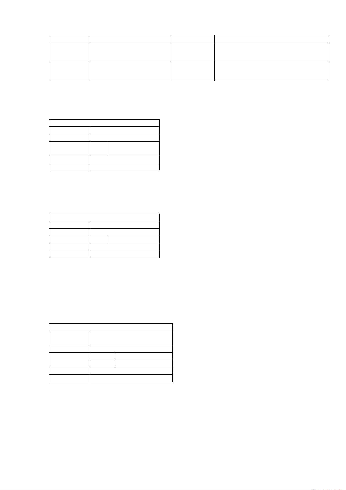
Version
Date
Author(s)
Description
A
11 June
First Release Version
6.3.2
Send ack marker ...................................................................................... 51
6.3.3 Send information ..................................................................................... 51
6.3.4 Send tags ................................................................................................ 51
6.3.5 Send sensor ............................................................................................. 51
6.3.6 Send parameter ....................................................................................... 51
6.3.7 Send all parameters ................................................................................. 51
7 TUTORIALS ......................................................................................... 52
7.1 Text on KR203 ............................................................................................... 52
7.1.1 Introduction............................................................................................. 52
7.1.2 Document Format .................................................................................... 52
7.1.3 Overview ................................................................................................. 52
7.1.4 Print graphics line .................................................................................... 53
7.2 Status from KR203 .......................................................................................... 54
7.2.1 Introduction............................................................................................. 54
7.2.2 Document Format .................................................................................... 54
7.2.3 Overview ................................................................................................. 54
7.2.4 Set up the printer..................................................................................... 54
7.2.5 Send status – <ESC><ENQ><1> .............................................................. 55
7.2.6 Send ACK marker – <ESC><ACK><N1> ................................................... 55
7.2.7 Monitoring when customer takes receipt.................................................... 57
7.2.8 Printing valuable vouchers ........................................................................ 57
7.2.9 Summary of commands used: ................................................................... 58
REVISION HISTORY
2013
P1066584-001 KR203 KPL Programming Manual Page 5 of 58
Page 6

1 Description
1.1 Purpose
This manual is for integrating KR203 into systems not using a printer driver supplied by Zebra
Technologies, for example embedded system using a proprietary controller and Operating
System.
1.2 Scope
This document covers the command set, settings and user interface of the KR203 kiosk
printer.
1.3 Document Format
In this document, binary data is represented in Zebra Toolbox format, which interprets data
within < and > symbols as binary data. Standard ASCII names such as <ESC> and <ENQ>
are converted to their equivalent binary values by Toolbox. Numbers such as <5> are sent
directly as binary d ata to the printer. Anything not appearing in bracket s, such as the & in
<ESC>&<4> is sent directly as ASCII text to the printer. See Toolbox help for more
information.
When values are specified in the format <N1 2> the space and the 2 indicate that the val ue
is a 16-bit value. Similarly, <N1 4> specifies that it is a 32-bit value.
P1066584-001 KR203 KPL Programming Manual Page 6 of 58
Page 7

Status LED State
Definition
Solid Yellow
Starting up. Present for about 100ms at first power on. If the solid
yellow stays, the printer failed RAM test and cannot start.
Solid Green
Printer OK
Flashing Red
Printer has detected a severe error. The patt ern of flashing signals
the error. See below for error table.
Flashing or Flickering
Green
Printer is receiving data.
Flash Pattern
Definition
* _ * _
Paper jam in presenter, Error Code 1
* * _ * * _
Cutter jam, Error Code 2
* * * _ * * * _
Out of paper, Error Code 3
* * * * _ * * * * _
Printhead lifted, Error Code 4
* * * * * _ * * * * * _
Paper feed error, Error Code 5
Amber On and Off
Head temperature error, Error Code 6
2 User Interface
2.1 User Interface Overview
The KR203 printer adapts the standard Zebra user interface used on the GX series desktop
products with a couple modifications and extensions. The printe r has four LEDs, two on each
side. The LEDs are labeled Power and Status. There is also a button labeled Feed on each
side.
The user interface is the same on each side. Neither the buttons nor the LEDs are individually
addressable.
The Power LED is green and is always on when 24V is applied to the unit. The Power LED
monitors only the 24V system.
The Status LED displays the current printer status. This LED is bi-col or, and can signal green,
red and yellow. The followi ng table explains the LED states when the feed button is not
pressed.
The KR203 printer has two pieces of software, a bootware and an application.
2.1.1 Application LED States
When the printer is flashing red the following error states can be signaled:
The lowest number error is always reported with the exception of error 4, head open. If the
head is open and the paper is out, the head open will be reported. All errors can be cleared
by the conditions causing them being removed, except cutter jam, which requires a power
cycle or reset command to be issued.
In addition “Paper jam in presenter” will clear automatically when the paper is removed from
the presenter, and “Head temperature error” will clear when the head cools sufficiently. See
“Status Codes” for more information.
P1066584-001 KR203 KPL Programming Manual Page 7 of 58
Page 8

While Button
Held
Meaning
Solid Green
Appears for 2 seconds, release during this time for a feed, cut and
present. Equivalent to command sequence <RS><0>.
One Flash,
then Solid Green
Release during this time to print the internal self test page. Equivalent
to command sequence <ESC>P<0>
Two Flashes,
Performs media guide detection, cutter calibration, and paper/TOF
sequence <ESC>g.
Three Flashes,
then Solid Green
Performs simulated USB cable disconnect and reconnect causing a
USB plug and play event to occur. No equivalent command.
Four Flashes,
Defaults all printer settings except “EOP Threshold”, and then
perform the calibration and resets all settings.
Five Flashes,
Prints a 50% grey pattern, cuts and ejects it; prints diagonal line
<ESC>P<4><ESC>P<5>
LED Off
Occurs if you continue to hold button beyond five flashes, releasing
button during this t ime does nothing.
Media Present
Meaning
Yes
Advances the media to the next mark in mark mode or the minimum
mode and then cuts media and presents minimum amount.
No
Prepares the printer for auto-load operation.
2.1.2 Application User Interface
The user interface is accessed via the feed button. To use the user interface, press and hold
the feed button. As soon as you depress the but ton, the user interface activates and signals
this by displaying a solid green LED on the status indicator.
The user interface can be accessed when the application is in an idle state, including while an
error has occurred. It cannot be accessed while the printer is already printing.
The function of the UI is dependent on how long the feed button is held. Continuing to hold
the button beyond a given entry in the t able proceeds to the next entry in the table.
then Solid Green
then Solid Green
then Solid green
calibration. Must be started with paper out or error is signaled, see
“Media Guide Detection” for more information. Equivalent to command
performs a media calibration. <ESC>&F<0> is similar but does not
pattern, cuts and presents it. Equivalent to command sequence
2.1.3 Additional UI Operations
In addition to the above items, the printer performs the following tasks:
When the printhead transitions from open to close the following operat ions occur :
amount of media required to maintain media control in continuous
2.1.3.1 Head Close Presenter Clearing
When the printhead is closed, the printer will attempt to clear the presenter if it detects
media is present at it and there is no media at the end of paper sensor. This is in preparation
for calibration. The calibration routine also does this check independently when media is
inserted.
2.1.3.2 Auto Load Operation (Calibration)
When the printer either starts up with no media present or the head is closed and no media
is detected, the printer prepares to auto load media. It also occurs after the defaulting as part
of the 4-flash operation.
P1066584-001 KR203 KPL Programming Manual Page 8 of 58
Page 9

Reasons For Calibrat ion Failure
Media is pulled out during 1 second start delay.
Head is opened at any time during operation.
In mark mode, printer fails to detect a the first mark within 625mm.
In plain paper mode if the white level of the media varies excessively and cannot be
stabilized within 625mm.
If entire calibration process does not complete within 1250mm.
If any printing has occurred since the last cut (On ly when used as a command)
If the printer detects media in the presenter and is unable to clear it
Parameter No.
Description
35
TOF synchronization
37
Page length
39
TOF marker length
40
Garbage filter
51
TOF marker sensitivity
58
Out of paper level
70
Presenter PWM percentage
When media is inserted into the rear of the printer, it is detected by the active media sensor,
and after a 1 second delay the printer begins to accept the media into the printer, and the
printer will perform a media calibration.
During the one second delay, presenter calibration is performed, so it is important to ensure
no media is present in the presenter when starting a calibration or media load. The firmware
ensures this by attempting to clear the presenter if it detects media present at it when media
is detected at the EOP sensor.
This media calibration occurs when the printer is both continuous and mark mode. In mark
mode, it requires two full forms to complete the calibration. The calibration type depends on
the “TOF Synchro nization ” paramete r. Calibration can fail for the following reasons:
When calibration fails, the media will be cut and ejected, and no error is signaled on the LED,
although a “Black mark calibration error” is reported to the host. If calibration succeeds,
calibration settings are stored. The “Black mark calibration error” is only reported if there are
no other severe errors active.
The following parameters are stored on a successful calibration:
2.1.3.3 Manual Media Loading
Media can also be loaded by opening the printhead, placing media under the printhead and
then closing the printhead. When this happens, no calibration occurs and previous calibration
settings are used. The printer will feed media the minimum amount, move to cut position, cut
and eject the media.
2.1.3.4 Media Guide Detection
When the media guide is changed, the printer will signal media present even when none is.
You must instruct the printer to detect the sensor it should use. This is accomplished with the
two flash function.
This process must be done without media in the printer. If the process is attempted with
media in the printer a “Media guide detection error” (Code 41) occurs. Upon successful
detection of the guide, guide settings are stored, and a “Media guide detection success”
(Code 42) message occurs. The “End of paper threshold” (Parameter 68) is captured during
guide detection along with the read only “Installed guide width” (Parameter 69).
P1066584-001 KR203 KPL Programming Manual Page 9 of 58
Page 10

Status LED State
Meaning
Rapid Flash Yellow
Firmware missing or corrupt
Fading in and out green
Bootware OK
Alternating Green-Red
Installing application – Do Not power off
Solid Off
Installing bootware – Do Not power off
2.1.3.5 Startup Behavior
The printer must ensure that at startup the printer is in a known state. When the printer is
powered on, it will make a small click to signal it has become ready.
2.1.3.6 Additional Notification
When settings are stored to flash with the <ESC>&<4> command, a small click will be made
to signal the storage.
2.1.4 Bootware User Interf ace
When the bootware is in error, holding the feed button down will signal the error condition:
Force entry into boot mode b y powering on the printer while holdi ng the feed button and
having the printhead open. Exit boot mode from a “Bootware OK” state by pressing and
holding the feed button for 10 seconds.
P1066584-001 KR203 KPL Programming Manual Page 10 of 58
Page 11

Command
Modes
Category
Description
Page
<ESC><ENQ><1>
A & B
Enquiry
Send status
12
<ESC><ACK>
A
Enquiry
Send ack marker
12
<ESC><ENQ>c
A & B
Enquiry
Send information
13
<ESC><ENQ><5>
A
Enquiry
Send sensor
13
<ESC><ENQ>P
A
Enquiry
Send parameter
14
<ESC><ENQ>Q
A
Enquiry
Send all parameters
14
Print uncompressed graphics
line
<ESC>J
A
Feed
Feed forward
15
<ESC>j
A
Feed
Feed backward
15
<FF>
A
Feed
Advance to TOF
15
<RS>
A
Feed
Cut and present media
15
<ESC><RS>
A
Feed
Cut media
16
<US>
A
Feed
Partial cut media
16
<ENQ>
A
Feed
Eject media
16
<ESC>?
A & B
System
Hard reset
17
<ESC>@
A
System
Soft reset
17
<ESC>&p
A
System
Set parameter in queue
17
<ESC>P
A
System
Print test page
17
<ESC>p
A
System
Force print
18
<ESC>&<4>
A
System
Store parameters
18
<ESC>&F
A
System
Recall parameters
18
<ESC><255>
A
System
Exit application
19
<ESC><0>
B
System
Load application
19
<ESC>#
A
System
Calibrate Media
20
<ESC>g
A
System
Calibrate System
20
3 Commands
3.1 Command Overview
The following is a table of all commands implemented in the KR203 Kiosk printer.
The Mode field indicates what modes the command is available in, A indicates it is available in
the Application; B indicates it is availa b le in Bootware.
<ESC>s A Graphics
14
P1066584-001 KR203 KPL Programming Manual Page 11 of 58
Page 12

Quick Command Facts
Name
Send status
Modes
Application and Boot
Parameters
None
Type
Enquiry
Execution
Immediate
Quick Command Facts
Name
Send ack marker
Modes
Application
Parameters
N1
Marker Number
0-255
Type
Enquiry
Execution
Synchronized, Initiate
3.2 General Notes on All Commands
Once transmission begins, a complete command must be received by the printer within 5
seconds. If the complete command is not received, the printer will automatically reset.
Commands marked “Immediate” will always operate as soon as they are parsed, regardless
of if there is any error conditions present.
Commands marked as “Synchronized” are placed into the printers command queue when
they are received.
Commands marked “Initiate” cause processing on the command queue to start as soon as
they are received by the printer.
Note that when any Severe error occurs, “Synchronized” commands that were present in the
print queue are not executed and are deleted. Some commands (such as Send ack marker)
do special things when they are deleted from the queue in this way. See individual
commands for more details.
Some of the parameters reference trays which are folders to store parameter data in. The
available trays are:
0 which is the current temporary values (these value s will be deleted during a power cycle)
1 which are the stored values (these values will rema in after a power cycle)
255 which are the default values of the firmware version loaded into the printer
3.3 Enquiry Commands
For all Enquiry commands, the status will be returned in the format selected by the “Status
protocol” parameter (number 66). The contents of the returned data vary based on the
selected protocol. See the “Status protocol” parameter, specifically the “Send Status” section
of the selected protocol.
3.3.1 Send status - <ESC><ENQ><1>
This command instructs the printer t o return its
current status to the host.
3.3.2 Send ack marker - <ESC><ACK><N1>
This command instructs the printer t o return an
ack marker to the host.
An ack marker is a marker that is returned to the
host when all the commands in the command
queue have been executed up to the point at
which the command was received. Executed
means physically printed in the case of motor or
feed commands, not just received by the printer.
N1 specifies the marker number to return. Resending the same marker will cause the same
marker to be returned twice.
P1066584-001 KR203 KPL Programming Manual Page 12 of 58
Page 13

Number
Name
Range
Description
0
Returns information on all available sensors
1
End of paper selected
0,1
Determines if paper is out at the selected
paper sensor
2
Top of form
0,1
Determines if the paper is currently at top of
form position
5
Paper at presenter
0,1
Determines if there is paper present under the
presenter sensor
9
Printhead temperature (C)
-57..122
Determines the printhead temperature in
degrees Celsius
10
Environment temperature (C)
-60..127
Not implemented on KR203 printer.
11
Head down
0,1
Determines if the printhead is in the down and
locked position
12
Cutter home
0,1
Determines if the cutter is in home position
13
Paper low
0..2
Determines if paper is detected at the paper
connected.
14
24V level (V)
0..50
Determines the voltage of the 24v supply
below 18 volts.
15
Media width
60,80
Determines the sensed guide width. Set during
guide width” setting.
16
FF button
0,1
Determines if the feed button is depressed.
individually addressable.
17
Pull detect
0,1
Determines if the presenter feed motor is
be active during print.
Quick Command Facts
Name
Send information
Modes
Application & Boot
Parameters
None
Type
Enquiry
Execution
Immediate
Quick Command Facts
Name
Send sensor
Modes
Application
Parameters
N1
Sensor Number,
or 0 for all.
Type
Enquiry
Execution
Immediate
The contents of the returned data vary based on the selected protocol. See the “Status
protocol” parameter, specifically the “Send ack marker” section of the selected protocol. If
the protocol supports it, the marker can either be positive, meaning all commands up to this
point were executed, or negative, ind icating that an error occurred on a command executed
before this point.
3.3.3 Send info r m ation - <ESC><ENQ>c
This command instructs the printer t o return
system information to the host.
See the “Status protocol” parameter, specifically
the “Send information” section of the selected
protocol.
NOTE! – This command takes several seconds to execute if information level setting in
parameter n67 is set to High.
3.3.4 Send sensor - <ESC><ENQ><5><N1>
This command instructs the printer to information
about a sensor to the host.
A value of zero indicates a negative “NO” for the
sensor. A value of one indicates a positive “YES”
for the sensor.
Table of Sensor Numbers:
P1066584-001 KR203 KPL Programming Manual Page 13 of 58
low sensor. The result is 2 if no sensor is
running into the printer. Printer will reset
calibration, and the same as the “Installed
The two feed buttons are ganged and not
currently sensing motion. Note that this may
Page 14
Number
Name
Range
Description
18
End of paper 80mm
0,1
Determines if paper is out at the 80mm sensor
guide.
19
End of paper 60mm
0,1
Determines if paper is out at the 60mm sensor
guide.
Quick Command Facts
Name
Send parameter
Modes
Application
Parameters
N1
Parameter
number
Type
Enquiry
Execution
Immediate
Quick Command Facts
Name
Send all parameters
Modes
Application
Parameters
N1
Tray Number
Type
Enquiry
Execution
Immediate
Quick Command Facts
Name
Print uncompressed graphics
line
Modes
Application
Parameters
N1
Data Size
N2…NX
Data
Type
Graphics
Execution
Synchronized
on the printer, regardless of the selected
on the printer, regardless of the selected
Specifying an inva lid sensor number for N1 will result in an “Index error”.
3.3.5 Send para meter - <ESC><ENQ>P<N1>
This command instructs the printer t o return a
parameter settings value.
N1 specifies the parameter number to return.
Specifying an invalid parameter number for N1
will result in an “Index error”.
For a list of available parameters see the “Parameters” section.
3.3.6 Send all parameters - <ESC><ENQ>Q<N1>
This command instructs t he printer to return all
parameters for a given tray value.
N1 specifies the tray to return.
The available trays are 0 which is the current
temporary values, tray 1 which are the stored
values and 255 which are the default values. Specifying a value for N1 other than these
values will result in an “Index error”.
3.4 Graphics Commands
3.4.1 Print graphics line - <ESC>s<N1><N2>..<nX>
This command sends a graphics stream to
the printer.
N1 specifies the stream size, which is the
number of bytes fron N2 to nX.
N2 specifies the graphic data to transmit to
the printer in raw binary format.
Any line for which less data than the current print width is specified, the remainder of the line
will be filled with blank dots. Excess data beyond the print width specified for a line will be
ignored.
When printing graphic lines, the print speed is deter mined by the burn time s ettings and the
compensation systems. The printer will drop speed when this occurs. Feed media commands
always moves media at the selected speed, so the rapid change between feed speed and
print speed can reduce print quality.
P1066584-001 KR203 KPL Programming Manual Page 14 of 58
Page 15

Quick Command Facts
Name
Feed forward
Modes
Application
Parameters
N1
Amount
Type
Feed
Execution
Synchronized
Quick Command Facts
Name
Feed backward
Modes
Application
Parameters
N1
Amount
Type
Feed
Execution
Synchronized
Quick Command Facts
Name
Advance to TOF
Modes
Application
Parameters
None
Type
Feed
Execution
Synchronized, Initiate
Quick Command Facts
Name
Cut and present media
Modes
Application
Parameters
N1
Present Amount
Type
Feed
Execution
Synchronized, Initiate
N1 Value
Amount Presented
0
50mm
1-254
1-254mm respectively
255
Entire page lengt h minus
20mm.
3.5 Feed and Cut Commands
3.5.1 Feed forward - <ESC>J<N1>
This command feeds media forward, i.e.
feeds without printing.
N1 specifies the amount to feed in motor
steps. There are approximately 8 steps per
mm.
The media feed always occurs at the selected print speed.
3.5.2 Feed backward - <ESC>j<N1>
This command feeds media backward.
N1 specifies the amount to feed in motor
steps. There are approximately 8 steps per
mm.
The media feed always occurs at the
selected print speed.
Note that it is possible to back the media out of the printer. A reverse operation at the start
of a page should ne ver exceed 7mm, or a N1 value of 56.
3.5.3 Advance to TOF - <FF>
This command feeds media to the next top
of form. The top of form position is either
when the next mark i s detected when “TOF
Synchronization” is enabled, or the “Page
Length” when in continuous mode.
If the setting “Auto Cut After TOF” is
enabled, a cut occurs after the movement, and the cut media is presented the default
amount (50mm).
3.5.4 Cut and present media - <RS><N1>
This command feeds media to the next top
of form. The top of form position is either
when the next mark i s detected when “TOF
Synchronization” is enabled, or the “Page
Length” when in continuous mode, and then
cuts the media.
The media is then presented based on the amount specified by N1:
The first time media is presented, the
parameter “Wall Compensation” is added to
the present amount.
Subsequent presentations do not have this
addition performed.
P1066584-001 KR203 KPL Programming Manual Page 15 of 58
Page 16

Quick Command Facts
Name
Cut media
Modes
Application
Parameters
None
Type
Feed
Execution
Synchronized, Initiate
Quick Command Facts
Name
Partial cut media
Modes
Application
Parameters
N1
Amount to leave
uncut in MM
Type
Feed
Execution
Synchronized, Initiate
Quick Command Facts
Name
Eject media
Modes
Application
Parameters
None
Type
Feed
Execution
Synchronized, Initiate
It is important to note that no presenting operation can cause the media to be completely
ejected from the printer. Only an eject command can completely remove the paper from the
printer. This cut is affected by the “Auto advance before cut” setting.
3.5.5 Cut m ed i a - <ESC><RS>
This command feeds media to the next top
of form. The top of form position is either
when the next mark i s detected when “TOF
Synchronization” is enabled, or the “Page
Length” when in continuous mode, and then
cuts the media.
No present operation occurs when using this command so a “Present media” command must
then be performed to present the media to the customer. This cut is affected by the “Auto
advance before cut” setting.
3.5.6 Partial cut media - <US><N1>
This command feeds media to the next top
of form. The top of form position is either
when the next mar k i s detected when “TOF
Synchronization” is enabled, or the “Page
Length” when in continuous mode, and then
partially cuts the media. The value specified
by N1 determines how much media is left
uncut in millimeters.
The amount specified is generally only accurate to 10mm increments, and has a range of 10-
60mm. Values above 60 result in no cut, a value of 0 results in a full cut, and is identical to
the <ESC><RS> command.
Note that if a partial cut fails, a full cut may occur in the process of trying to resolve the
error, but the customer will still be able to get both of their receipts, just fully separated.
A complete cut operation must be performed before the media can be ejected. This cut is
affected by the “Auto advance before cut” setting.
3.5.7 Eject media - <ENQ>
P1066584-001 KR203 KPL Programming Manual Page 16 of 58
This command completely ejects a cut piece
of media from the presenter.
This command does nothing if the media has
not been cut yet.
Page 17

Quick Command Facts
Name
Hard reset
Modes
Application & Boot
Parameters
None
Type
System
Execution
Immediate
Quick Command Facts
Name
Soft reset
Modes
Application
Parameters
None
Type
System
Execution
Immediate
Quick Command Facts
Name
Set parameter in queue
Modes
Application
Parameters
N1
Parameter Number
N2…NX
Parameter Value
Type
System
Execution
Synchronized
Quick Command Facts
Name
Print test page
Modes
Application
Parameters
N1
Type of page
Type
System
Execution
Asynchronous, Initiate
3.6 System Commands
3.6.1 Ha rd reset - <ESC>?
3.6.2 So f t reset - <ESC>@
This command performs a hard printer reset.
This is equivalent to a power cycle.
When in the bootware, this command is
used to exit the bootware and start
execution of the application, provided a valid
application is installed.
This command performs a software reset of
the printer. A software reset resets all
communication interfaces, and emp ties all
queues and buffers.
3.6.3 Set parameter in queue - <ESC>&p<N1><N2>..<NX>
different sizes in the KR203, so it is critical to send the proper number of bytes for a given
setting.
If N1 is an invalid parameter number, an “Index error” will occur. If the value specified by
N2..NX is outside the valid range for parameter N1, an “Out of range” will occur.
For a list of available parameters see the “Parameters” section.
This command just loads the setting into the operating parameters; to store them, use
<ESC>&<4><1>
3.6.4 Print test page - <ESC>P<N1>
value for N1 will result in an “Index error”.
The execution of this command is Asynchronous, meaning that while it will be executed in
queue order; commands around it may also be executed at the same time. For this reason,
when executing these commands, other printing commands should not be executed; however
additional test pages can be executed.
P1066584-001 KR203 KPL Programming Manual Page 17 of 58
This command sets a parameter in the
printer. Parameters control all system
options in the printer.
N1 specifies the parameter number to set.
N2 to NX specifies a binary value to set the
parameter to. Different parameters are
This command instructs the printer to print a
built in test page.
N1 specifies the type of page to print. See
the table below for more details. Each print
is followed by a move to cut position, and a
cut and default eject. Specifying an invalid
Page 18

N1 Value
Page Description
Continuous Mode Length
0
Self test page – Displays logo and firmware
version number
92mm
3
25% staggered dot page
177mm of printing, 190mm
total
4
50% 1-dot page
177mm of printing, 190mm
total
5
2-bit rotating pattern page
177mm of printing, 190mm
total
6
50% 2-dot page
177mm of printing, 190mm
total
7
Density pattern page
152mm of printing, 165mm
total
Quick Command Facts
Name
Force print
Modes
Application
Parameters
None
Type
System
Execution
Immediate, Initiate
Quick Command Facts
Name
Store parameters
Modes
Application
Parameters
N1
Tray to store
parameters in
Type
System
Execution
Immediate
Quick Command Facts
Name
Recall parameters
Modes
Application
Parameters
N1
Tray to load
parameters from
Type
System
Execution
Immediate
When “TOF Synchronization” is enabled, after the page is completed, the printer will advance
to the next mark, then cut and eject.
3.6.5 Force print - <ESC>p
This command forces all items in the
printer’s queue to be executed immediately
upon receipt of this command.
Note that when there is a severe error, the
queue is emptied, so sending this command
during a severe error has no effect.
3.6.6 St ore parameters - <ESC>&<4><N1>
This command instructs the printer to store
the current operating parameters in flash,
making them the power on settings.
N1 specifies the tray to store the parameters
in. Tray 1 is the only t ray present on the
KR203. Specifying an invalid tray will result
in an “Index error ”.
After execution of this command is complete, the printer will make a small click noise to give
the user acknowledgement that the save has occurred.
Note that parameters set with <ESC>&p as well as any temporary parameters send by an
installed driver will be stored via this command.
3.6.7 Recall parameters - <ESC>&F<N1>
This command instructs the printer to load
the current operating parameters from the
specified tray.
N1 specifies the tray to load the parameters
from.
On the KR203, tray 1 holds the parameter
values stored in flash, and tray 255 holds the factory defaul t values. Specifying any other
value will result in an “Index error”.
P1066584-001 KR203 KPL Programming Manual Page 18 of 58
Page 19

Quick Command Facts
Name
Exit application
Modes
Application
Parameters
Boot or application PID
Type
System
Execution
Immediate
Quick Command Facts
Name
Load application
Modes
Boot
Parameters
Components of application
file
Type
System
Execution
Immediate, Initiate
This command just loads the specified set into the operating parameters; to store them, use
<ESC>&<4><1>.
3.6.8 Exit application - <ESC><255><n1>
This command exits the application and
enters the bootware. When the application is
terminated all data present in that session is
lost.
When this command is issued, the printer
will leave the USB bus and return as either
the same or a different device.
If n1=0, the boot loader w i ll return with the boot loader USB ID (PID = 0x0 0B 4)
If n1=1, the boot loader w i ll return with the firmware’s USB ID (P ID = 0x0 0B3)
You should use interactive polling to ensure you entered boot mode successfully.
To exit the boot and start the application, use the <ESC>? co mmand.
3.6.9 Load application - <ESC><0><Application data>
The sequence for firmware (application) update has to be interactive:
1) Send: <ESC><255><0> or <ESC><255><1>
If you use 0, the boot loader will come up with a boot loader USB ID string. If you use 1,
it will come up with the firmware’s ID string and you should use interactive polling to
ensure you entered boot mode successfully. In W indows 7 and above it is best to use 1
as a change of identity requires a new driver and administrative rights to load.
2) Wait for the USB Device to leave the bus and then reenter.
3) Send: <ESC><0><firmware file>
4) Verify load complete and successful.
5) <ESC>? Reset printer to exit the boot.
6) Wait for the USB device to re-appear.
7) Verify update.
This command instructs the bootware that it
should load a new application.
When this command is issued, an application
file is to follow.
The first four bytes of the application file is
the file size, and the boot first checks to
make sure the new application will fit between the boot and the flash disks. If it does not, a
“Boot/Application version mismatch” error occurs.
Next, the application is checked to ensure it is a n ap p lication file, this is accomplished via the
tagging mechanism in the firmware files. If the file is not detected to be an application file a
“Wrong object type” error occurs.
P1066584-001 KR203 KPL Programming Manual Page 19 of 58
Page 20

Quick Command Facts
Name
Calibrate Media
Modes
Application
Parameters
None
Type
System
Execution
Synchronized, Initiate
Quick Command Facts
Name
Perform System Calibration
Modes
Application
Parameters
None
Type
System
Execution
Immediate
The printer must have been previously programmed with tags in order to load any file,
application or bootware. If the current bootware cannot find the system tags on the printer’s
flash disk, or if the bootware cannot find any tag entries in the first 2k of the application file,
a “Tag system not found” error occurs.
Next it is checked for compatibility with this specifi c controlled PCB. If the bootware file is not
detected as being compatible with this board, a “Wrong target” error occurs.
As the application is received by the printer, it is burned directly to flash memory.
After the entire application has been received and flashed to the application flash space, a
checksum is then received by the printer, which is the final four bytes of the application file.
If the checksum pr ovided and the checksum of the data in flash do not match, a “Checksum
error” occurs.
After a successful load, there is a single 50ms writ e operation to the boot area to inform it
where the new application starts in memory. If the printer is powered off during the
application, the printer might not be recoverable.
After successful load, the printer remains in the bootware. To exit the bootware, issue an
<ESC>?.
3.6.10 Calibrate Media - <ESC>#
This command instructs the printer to
perform a media calibration.
Media calibration can be done for both
continuous and mark based media, and the
type of calibration performed is based on the
option selected by the “TOF
Synchronization” p arameter. See more details in the user interface section for what occurs
during calibration.
The media calibration process must begin with n o other print in progress. If it is attempted
while there is a print out in progress, the printer will cut and eject the page, and signal a
“Black mark calibration error”.
Sending this command multiple times will only cause one calibration until the calibration
which is active is complete.
3.6.11 Calibrate System - <ESC>g
This command instructs the printer t o select
media guide, and calibrate cutter and media,
If TOF synchronization if enabled through
parameter n35, the printer will be calibrated
for the TOF media loaded.
System calibration triggered with this
command is the same as holding the Feed button pressed until two blinks.
In order to start this process, no media must be present under the platen or under the
presenter sensor, the printhead must be closed, and no cutter jam must exist.
If these conditions are not met, a “System calibration error” occurs. If the calibration is
successful, a “System calibration success” occurs.
P1066584-001 KR203 KPL Programming Manual Page 20 of 58
Page 21

This command also calibrates the cutter, so it is normal that as part of its execution 3 cuts
occur. If the cutter calibration cannot compete successfully, a “Cutter jam” error occurs.
Upon successful calibration of the media guide, “End of paper threshold”, “Installed guide
width”, “Cutter calibration” and “Presenter threshold” are stored to flash.
P1066584-001 KR203 KPL Programming Manual Page 21 of 58
Page 22

Number
Name
Range
Default
Size
Attributes
6
Secondary burn time
10..900
130
2
None
7
Primary burn time
10..2600
560
2
None
8
Max print speed
50..175
152
1
None
9
Presenter loop length
0,80..600
400
2
None
31
Presenter speed
50..450
300
2
None
34
Auto cut and present after FF
0..1
0
1
None
35
TOF synchronization
0..1
0
1
None
37
Page length
11..600
85
2
None
39
TOF marker length
1..30
5
1
None
40
Garbage filter
1..15
1
1
None
41
TOF cut offset
0..255
0
1
None
45
Eject Timeout
0..600
0
2
None
46
Cut position calibration
-127..127
0
1
None
47
Wall Compensation
0..600
0
2
None
48
Print width
0,20..80
0
1
None
49
Advance before cut
0..1
1
1
None
51
TOF marker sensitivity
0..255
120
1
None
53
Lock parameters
0..1
0
1
None
57
System
0..255
255
1
None
58
Out of paper level
0..255
0
1
None
65
Status mode
0,1,3
3
1
None
66
Status protocol
0..1
1
1
None
67
Information level
10,20,30
10
1
None
68
End of paper threshold
0..235
60
1
None
69
Installed guide width
60,80
80
1
Read Only
70
Presenter PWM percentage
0..100
100
1
None
71
EOP PWM percentage
0..100
100
1
None
75
Keepalive timeout
0..65535
0
2
None
80
Compensation mode
0..255
255
1
None
81
Compensation curve knee
1..1000
88
2
None
82
Compensation curve divisor
1..10000
1000
2
None
83
Compensation slope
1..1000
610
2
None
84
Compensation Y-intercept
1..10000
1481
2
None
248
Last reset reason
10,20,30,40,50,60,70
10
1
Read Only
249
Power down count
(All values valid)
0
4
Read Only
250
Media length (m)
(All values valid)
0
4
Read Only
251
Number of cuts
(All values valid)
0
4
Read Only
252
MIFS low page erases
(All values valid)
0
4
Read Only
253
MIFS high page erases
(All values valid)
0
4
Read Only
254
Uptime (s)
(All values valid)
0
4
Read Only
4 Parameters
4.1 Parameters Overview
The following is a table of all parameters implemented in the KR203 Kiosk printer.
For any parameter, if the value specified is not in the range, an “Out of range” error occurs.
P1066584-001 KR203 KPL Programming Manual Page 22 of 58
Page 23

Darkness
Total burn time
N6
N7
5%
33
6
28
10%
67
12
55
15%
100
18
82
20%
133
24
110
25%
167
30
137
30%
200
36
164
35%
233
42
192
40%
267
48
219
45%
300
54
246
50%
333
60
274
55%
367
66
301
60%
400
72
328
65%
433
78
356
70%
467
84
383
75%
500
90
410
80%
533
96
438
85%
567
102
465
90%
600
108
492
95%
633
114
520
100%
667
120
546
105%
700
126
574
110%
733
132
602
115%
767
138
629
120%
800
144
656
125%
833
150
684
130%
867
156
711
135%
900
162
738
140%
933
168
766
145%
967
174
793
150%
1000
180
820
Parameter Facts
Number
6
Name
Secondary burn time
Range
10..900
Size
Unsigned 16-bit
Default
120 (µS)
Parameter Facts
Number
7
Name
Primary burn time
Range
10..2600
Size
Unsigned 16-bit
Default
546(µS)
4.1.1 6 – Second ary burn time
When “Compensation mode” bit 2 is
enabled, this is the amount of time spent
burning the history control dot line during
printing, it is ignored otherwise.
History lines give extra burn time to pixels
which have been off in order to improve
print darkness on those dots.
The time is specified in microseconds. Note that setting this val ue to a high number can
reduce print speed.
4.1.2 7 – Primary b urn t ime
T is the amount of time spent burning the
dot line during printing.
The time is specified in microseconds. Note
that setting this value to a high numbe r can
reduce print speed.
Using very large values ca n reduc e printhead life. Generally there is no reason to set this
above 1000.
P1066584-001 KR203 KPL Programming Manual Page 23 of 58
Page 24

Parameter Facts
Number
8
Name
Max print speed
Range
50..175
Size
Unsigned 8-bit
Default
152 (mm/s)
Parameter Facts
Number
9
Name
Presenter loop length
Range
0,80..600
Size
Unsigned 16-bit
Default
400 (mm)
Parameter Facts
Number
31
Name
Presenter speed
Range
50..450
Size
Unsigned 16-bit
Default
300 (mm/s)
Parameter Facts
Number
31
Name
Auto cut and present after FF
Range
0..1
Size
Unsigned 8-bit
Default
0 (Disabled)
Parameter Facts
Number
35
Name
TOF Synchronizatio n
Range
0..1
Size
Unsigned 8-bit
Default
0 (Disabled)
4.1.3 8 – Max print speed
This parameter specifies the maximum print
speed. This speed is used as the feed speed.
The value specified is in millimeters per
second. It is not advised to set this value
less than 75 or over 152.
4.1.4 9 – Presenter loop length
This parameter specifies the maximum
media length stored in the presenter loop
during printing. Once this much media is
stored in the loop, it begins feeding out as
more is printed.
The value specified is in millimeters. A value
of zero indicates no loop. Note that because of gearing differences in the motors, the size of
the loop will slowly increase as more printing occurs, even if the loop is disabled.
4.1.5 31 – Presenter speed
This parameter specifies the speed the
presenter moves media at when presenting
and ejecting. It does not control the speed
when maintaining t he height of the loop.
The value specified is in millimeters per
second.
4.1.6 34 – Auto cut and present after FF
This parameter specifies whether or not the
printer automatically cuts and presents after
an <FF> command.
A value of zero performs no cut after <FF>,
a value of 1 causes a cut and default present
to occur after <F F>, equivalent to an
<RS><0>
4.1.7 35 – T OF Sync hr onization
This parameter specifies whether the printer
should sync to TOF (Black) marks or not.
A value of 0 places the printer in continuous
mode.
A value of 1 places the printer in TOF
synchronization mode.
If you attempt to use mark media in continuous mode, normal ope ration occurs unless the
marks are larger than the value specified by “TOF marker length”. If this is the case, media
out may be signaled when a mark is encountered.
P1066584-001 KR203 KPL Programming Manual Page 24 of 58
Page 25

Value
Result
0
Continuous Mode
1
TOF Synchronization Mode
Parameter Facts
Number
37
Name
Page length
Range
11..600
Size
Unsigned 16-bit
Default
92 (mm)
Parameter Facts
Number
39
Name
TOF marker length
Range
1..30
Size
Unsigned 8-bit
Default
5 (mm)
Parameter Facts
Number
40
Name
Garbage filter
Range
1..15
Size
Unsigned 8-bit
Default
1 (mm)
Parameter Facts
Number
41
Name
TOF cut offset
Range
0..255
If you attempt to use continuous media in mark mode, at the end of each page, the printer
will feed media for twice the “Page length” searching for the mark. If it is not found, a “Black
mark not found” error occu rs.
4.1.8 37 – Page length
This parameter specifies the length of a
page.
When “TOF Synchronization” is enabled,
twice this value is the length of media that
will be fed searching for the next valid mark
to cut at.
When it is disabled, this represents the minimum page length that the pri nter will produce.
This setting is set automatically during a calibration when “TOF Synchronizat ion” is enab led .
Page length is always resolved jus t before a cut operation.
Generally speaking, the printer will always regard this setting when making any cut. Note that
during startup, the printer may cut without regard to this setting. This is by design and
needed to avoid a paper jam at startup.
4.1.9 39 – TOF marker length
This parameter specifies the maximum
length of a mark, and is measured in
millimeters.
If a mark is longer than this value plus 5mm,
a media out condition is signaled.
This setting is set automatically during a calibration when the calibration was started while
“TOF Synchronization” is enabled.
4.1.10 40 – Garbage filter
This parameter specifies how big a mark
must be to be detected as a mark.
If a mark is shorter than this, it is ignored.
This setting is set automatically during a
calibration when the calibration was started
while “TOF Synchronization” is enabled.
4.1.11 41 – TOF cut offset
P1066584-001 KR203 KPL Programming Manual Page 25 of 58
Page 26

Size
Unsigned 8-bit
Default
0 (mm)
Parameter Facts
Number
45
Name
Eject timeout
Range
0..600
Size
Unsigned 16-bit
Default
0 (Seconds)
Parameter Facts
Number
46
Name
Cut position calibration
Range
-127..127
Size
Signed 8-bit
Default
0 (steps)
Parameter Facts
Number
47
Name
Wall Compensation
Range
0..600
Size
Unsigned 16-bit
Default
0 (mm)
Parameter Facts
Number
48
Name
Print width
Range
0,20..80
Size
Unsigned 8-bit
Default
0 (automatic based on n69)
Parameter Facts
This parameter specifies how much media
should be fed once a mark is detected
before media is considered to be in cut
position. It has no effect when “TOF Synchronization” is not enabled.
Note that additional marks can be found in the interim and this will have no effect on the
operation, and may desynchronize the mark system.
4.1.12 45 – Eject timeout
This parameter specifies how long the
printer waits after a present operation
occurs before it automatically ejects the
page.
If this value is set to zero, no eject will
occur. Note that the time is measured from
the completion of the first present operation.
4.1.13 46 – Cut position calibration
This parameter is used to set how many
steps the cut position is to be modified by.
Note that this is a signed 8 bit value.
Negative values will cause the printer to cut
sooner than default position. Note that the
adjustment will never result in a reverse
feed.
4.1.14 47 – Wall compensation
This parameter is used to set the t hickness
of the kiosk wall. This value is added to the
first present operation of any printed page
as an additional feed. It only applies to the
first present operation of a given page,
subsequent feeds will be at their actual
values.
Note that the presenter will never lose control of the media with a present operation. Eject
cannot occur using present commands.
4.1.15 48 – Print width
This parameter is used to set the desired
print width output. This setting overrides
setting 69, “Installed guide width” and
instructs the system to print in the specified
width in millimeters.
The print window will always be centered.
If this value is 0, the value is based on “Installed guide width” and is 54 if a narrow guide is
detected and 72 if a wide guide is detected.
4.1.16 49 – Advance before cut
P1066584-001 KR203 KPL Programming Manual Page 26 of 58
Page 27

Value
Result
0
Do not advance before cut
1
Advance before cut
Value
Result
0
Do not lock parameters
1
Lock parameters
Number
49
Name
Advance before cut
Range
0..1
Size
Unsigned 8-bit
Default
1 (Enabled)
Parameter Facts
Number
51
Name
TOF marker sensitivity
Range
0..255
Size
Unsigned 8-bit
Default
122 (AD Steps)
Parameter Facts
Number
53
Name
Lock parameters
Range
0..1
Size
Unsigned 8-bit
Default
0 (Unlocked)
Parameter Facts
Number
57
Name
System
Range
0..255
Size
Unsigned 8-bit
Default
255
Parameter Facts
Number
58
Name
Out of paper level
If this parameter is set to 1, meaning it is
enabled, the printer will feed the print line to
cutter distance before it tries to move to cut
position. A value of zero means no motion
occurs, which means that part of the
previous page will appear on the top of the
next page.
Because the print line to cutter distance is less than the EOP sensor to print line distance, this
should never cause an extra form to be fed when “TOF synchronization” is enabled.
4.1.17 51 – TOF marker sensitivity
This setting determines what level the
selected EOP sensor must see before it
starts evaluating whether or not a detected
mark is valid. This is a detection done prior
to the garbage filter detection.
This is set during media calibration when
“TOF synchronization” is enabled.
4.1.18 53 – Lock parameters
This value specifies if parameters can be
changed using the <ESC>&p command.
When set to 1, setti ng any parameter other
than this one results in an “Index err or”.
Note that the “Recall parameters” command
overrides this setting.
4.1.19 57 – System
The System parameter is a bit field that will
control up to eight system components in
the printer. Bits 0-6 are unspecified and
should always remain set to 1.
Bit7 1: default. One PC /one KR203 USB
driver instance regardless of USB port used;
0: each USB port has its own KR203 USB driver instance.
4.1.20 58 – Out of paper level
P1066584-001 KR203 KPL Programming Manual Page 27 of 58
Page 28

Value
Result
0
No active status reporting
3
Report active status to USB port
Value
Result
0
TTP Reporting
1
XML Reporting
Value
Result
10
Minimum Information Level
20
Medium Information Level
30
Maximum Information Level
Range
0..255
Size
Unsigned 8-bit
Default
0
Parameter Facts
Number
65
Name
Status mode
Range
0 and 3
Size
Unsigned 8-bit
Default
3 (Active to USB)
Parameter Facts
Number
66
Name
Status protocol
Range
0..1
Size
Unsigned 8-bit
Default
1 (XML Reporting)
Parameter Facts
Number
67
Name
Information Level
Range
10,20,30
Size
Unsigned 8-bit
Default
30 (Maximum information)
This parameter is not currently used and is
set during calibration.
4.1.21 65 – Status mode
This setting determines the status reporting
behavior of the KR203.
When set to 3, the printer will actively report
status changes. These responses are
equivalent to the responses generated by
<ESC><ENQ><1>. The reporting format
will vary based on the value of “Status protocol” (parameter 66).
These requests will be generated automatically, without an enquiry. For a list of the codes
generated, see “Status codes”.
4.1.22 66 – Status protocol
This setting determines the status reporting
protocol of the KR203 printer.
All data that is returned by the printer will be
in a format supported by the specified
protocol.
For a detailed reference of the responses of each protocol, see the “Status protocols” section.
4.1.23 67 – Information Level
This setting determines the amount of
information to be reported when using the
“XML Reporting” option as selected by the
“Status protoco l” setting.
It only applies to the “XML Reporting”
option, and does nothing when any other
protocol is enabled.
P1066584-001 KR203 KPL Programming Manual Page 28 of 58
Page 29

Value
Result
60
60 (or 58mm) guide installed
80
80 (or 82.5mm) guide installed
Parameter Facts
Number
68
Name
End of paper thresho ld
Range
0..255
Size
Unsigned 8-bit
Default
60 (AD Steps)
Parameter Facts
Number
69
Name
Installed guide width
Range
60,80
Size
Unsigned 8-bit, read on ly
Default
80 (or 82.5mm)
Parameter Facts
Number
70
Name
Presenter PWM percentage
Range
0..100
Size
Unsigned 8-bit
Default
100 (percent)
Parameter Facts
Number
71
Name
EOP PWM percentage
Range
0..100
Size
Unsigned 8-bit
Default
100 (percent)
Parameter Facts
Number
75
For a detailed reference of the responses at each information level, see the “Status protocols”
section.
4.1.24 68 – End of paper threshold
This setting determines the thresholds for
the EOP sensor to determine if the printer is
out of paper. This is in addition to the
detection system afforded by the mark
detection system (which is if the mark length
is greater than “TOF marker length” plus
5mm).
This value is set after a successful media guide calibr ation.
4.1.25 69 – Installed guide width
This setting instructs the system which EOP
sensor to use, either the sensor for wide
guides or the sensor for narrow guides.
This value is set after a successful media
guide calibration.
4.1.26 70 – Presenter PWM percentage
This setting instructs the system what
amount of time the LED should be turne d on
per cycle. 100% is equal to full on, 0% is
equal to full off. This setting controls the
presenter sensor’s PWM.
This value is set after a successful media
calibration, regardless of the “TOF Synchronization” setting. This parameter should not be
manually set.
4.1.27 71 – EOP PWM percentage
This setting instructs the system what
amount of time the LED should be turne d on
per cycle. 100% is equal to full on, 0% is
equal to full off. This setting controls both
EOP sensor’s PWM.
This parameter should not be manually set.
4.1.28 75 – Keepalive timeout
P1066584-001 KR203 KPL Programming Manual Page 29 of 58
Page 30

Bit Number
Value to Add
Definition
0 1 Enable Thermal Compensation
Decreases burn time based on head temperature.
1 2 Enable Speed Compensation
Increases or decreases burn time based on print speed.
2 4 Enable Secondary Burn
Enables the history system, and burns history lines at the “Secondary burn time” time
Name
Keepalive timeout
Range
0..65535
Size
Unsigned 8-bit
Default
60
Parameter Facts
Number
80
Name
Compensation mode
Range
0..255
Size
Unsigned 8-bit (bit field)
Default
255 (all enabled)
If active status reporting is enabled (see
“Status mode”), this setting instructs the
system to send back an active status
message at regular intervals as specified by
this parameter. The parameter is measured
in seconds.
Once an active status message is sent, a timeout is started based on this value. If no new
active status message occurs during that time, a special keepalive status message will be
transmitted based on the currently selected status protocol (see “Status protocol”). The timer
always resets when the system broadcasts any active status message or keepalive message.
A value of zero indicates that this function is disabled, all other values indicate the timeout in
seconds.
4.1.29 80 – Compensation mode
This setting instructs the system to enable
or disable various printing compensation
systems.
These systems can change the values
specified by “Primary burn ti me”.
This parameter is a bit field parameter, add the values below to get the desired effect.
Note that enabling or disabling these settings can have an effect on print speed during
printing.
P1066584-001 KR203 KPL Programming Manual Page 30 of 58
Page 31

Value
Meaning
10
Reset from power loss
20
Reset by command
30
Reset by request to enter boot
40
Reset by brownout (voltage dipped below 18 and then rose above 22v)
50
Reset by software watchdog
60
Reset by operating system error
70
Reset by bad interrupt
Parameter Facts
Number
81
Name
Compensation curve knee, k
Range
0..1000
Size
Unsigned 16-bit
Default
88 (× 10)
Parameter Facts
Number
82
Name
Compensation curve divisor, d
Range
0..1000
Size
Unsigned 16-bit
Default
1000 (× 10)
Parameter Facts
Number
83
Name
Compensation slope, l
Range
0..1000
Size
Unsigned 16-bit
Default
610 (× 10)
Parameter Facts
Number
84
Name
Compensation Y-intercept, y
Range
0..10000
Size
Unsigned 16-bit
Default
1481 (× 10)
Element
Meaning
Time head has been off in µS
Compensation Y-intercept
Primary burn time value in µS
Secondary burn time value in µS
Compensation slope
Compensation knee
Compensation divisor
Result in µS to add to the primary burn
Parameter Facts
Number
248
Name
Last reset reason
Range
10,20,30,40,50,60,70
Size
Unsigned 8-bit, read-only
Default
10 (Reset from power loss)
4.1.30 81 – 84 Compensation
These four settings are used by the speed compensation system determine how much to
compensate the burn by based on the following formula:
(
)
=
+
The total amount of time burned when speed compensation is enabled cannot exceed the
minimum step length by more than a small amount, so the net speed impact is small. Also
speed compensation never reduces burn, only increases it.
4.1.31 248 – Last reset reason
This value contains the last reason the
printer reset.
This value is read only
P1066584-001 KR203 KPL Programming Manual Page 31 of 58
Page 32

Parameter Facts
Number
249
Name
Power down count
Range
(All values valid)
Size
Unsigned 32-bit, read only
Default
0
Parameter Facts
Number
250
Name
Media length
Range
(All values valid)
Size
Unsigned 32-bit, read only
Default
0
Parameter Facts
Number
251
Name
Number of cuts
Range
(All values valid)
Size
Unsigned 32-bit, read only
Default
0
Parameter Facts
Number
252
Name
MIFS low page erases
Range
(All values valid)
Size
Unsigned 32-bit, read only
Default
0
Parameter Facts
Number
253
Name
MIFS high page erases
Range
(All values valid)
Size
Unsigned 32-bit, read only
Default
0
Parameter Facts
Number
254
Name
Uptime (s)
Range
(All values valid)
Size
Unsigned 32-bit, read only
Default
0
4.1.32 249 – Power down count
4.1.33 250 – Media length (m)
This value is the number of times the printer
has been powered down. It is not
incremented when a brownout occurs.
This value is the total length of media fed by
the platen motor in meters. It is reported in
meters but tracked in platen steps.
4.1.34 251 – Number of cuts
This value is the total number of times the
cutter blades have contacted. This includes
normal cuts, partial cuts and retry cuts.
4.1.35 252 & 253 – Page Erases
These two values store the number of times
the printers two flash disks have been
written to. The printer has a mirroring
system for the flash disk, and these counters
track the number of writes to each one.
Each flash disk is rated for, at minimum,
50,000 writes.
4.1.36 254 – Uptime (s)
This value is the total number of seconds
the controller PCB has been powered.
P1066584-001 KR203 KPL Programming Manual Page 32 of 58
Page 33

Number
Name
Type
Group
LED
Reporting
0
Ok
Normal
Informational
Solid green
1
Paper jam in presenter
Normal
Severe
1 red flash
2
Cutter Jam
Normal
Severe
2 red flashes
3
Out of paper
Normal
Severe
3 red flashes
4
Printhead lifted
Normal
Severe
4 red flashes
5
Paper feed error
Normal
Severe
5 red flashes
Head temperature error
Normal
Severe autoclear
Yellow
flashing
Black mark not found
Onetime
Informational
Not signaled
Black mark calibration
error
Onetime
Informational
Not signaled
Index error
Onetime
Informational
Not signaled
Out of range
Onetime
Informational
Not signaled
19
Paper low
Normal
Warning
Not signaled
20
Media in presenter
Normal
Informational
Not signaled
Printer entered USB
bus
Onetime
Informational
Not signaled
Media guide detection
error
Onetime
Informational
Not signaled
Media guide detection
success
Onetime
Informational
Not signaled
5 Status Codes
5.1 Application Status Code Overview
The following table is all status codes that can be reported by the KR203 printer from the
application.
6
10
11
12
18
40
41
42
5.2 Groups, Types and Reporting
The group and type values in the above table are important pieces of information to know
how to deal with a status.
Type
Items in the above table marked “One-time” will only be reported to the host once; that is as
soon as they are transmitted to the host, either as part of an active status report if “Status
mode” is set in such a way, or after a query such as “Send stat us”, they are automatically
cleared.
“Normal” type status messages will continue to be reported until the status changes.
Reporting
Severe errors are reported to the user via the user interface using the status LED. The order
of the above list expresses the order i n which they are reported on the user interface.
P1066584-001 KR203 KPL Programming Manual Page 33 of 58
Page 34

Category
Group
value
Meaning
Severe
1
A serious error has occurred and a te chnician will be required to resolve it.
Severe auto-clear
10
A serious error has occurred, but it may clear on its own given time.
Warning
30
An error may occur in the future.
Informational
100
Information only, there is no risk of error.
Status Code Facts
Number
0
Name
Ok
Type
Normal
Group
Informational
LED Reporting
Solid Green
Status Code Facts
Number
1
Name
Paper jam in presenter
Type
Normal
Group
Severe
LED Reporting
1 red flash
Status Code Facts
Number
2
Name
Cutter jam
Type
Normal
Group
Severe
LED Reporting
2 red flashes
When status is requested, all status codes that are a ctive will be returned to the user each
time the information is requested. Additionally, if the status changes and is reported actively,
it will be re-reported when any status changes .
For example, if the head is open and the printer is out of media, an active status report will
arrive showing both these codes. If the head is the n closed but media is not present, an
additional active status report will be issued that informs the host that only media is out.
Groups
Groups allow the host to make determinations about what to do with an error without
knowing what the er ror means. In addition to the above names, groups are assigned
numbers reported in the status report.
These codes give an indication of how the host should handle each of these classes of errors
if it does not know what a certain status code means.
5.2.1 0 – Ok
5.2.2 1 – Paper jam in presenter
from the presenter sensor.
This code is reported when no other codes
are active. It indicates that everything is
okay.
This code indicates that media is stuck in the
presenter. This error is set when the printer
attempts to eject media completely, and
cannot complete the operation after feeding
the length of the page plus 175mm.
It can be cleared by removing the media
5.2.3 2 – Cutter Jam
This code indicate s that the printer could not
find the cutter blade or could not properly
manage its position.
This error is set when the printer attempts
to cut but fails, and three retries also fail.
It can be cleared by power cycle only.
P1066584-001 KR203 KPL Programming Manual Page 34 of 58
Page 35

Status Code Facts
Number
3
Name
Out of paper
Type
Normal
Group
Severe
LED Reporting
3 red flashes
Status Code Facts
Number
4
Name
Printhead lifted
Type
Normal
Group
Severe
LED Reporting
4 red flashes
Status Code Facts
Number
5
Name
Paper feed error
Type
Normal
Group
Severe
LED Reporting
5 red flashes
Status Code Facts
Number
6
Name
Head temperature error
Type
Normal
Group
Severe auto-clear
LED Reporting
Yellow flashing
Status Code Facts
Number
10
Name
Black mark not found
Type
One-time
Group
Informational
LED Reporting
Not signaled
5.2.4 3 – Out of paper
This code indicates that the selected EOP
sensor has detected no media present. This
value is signaled either when the mark
engine has detected a mark larger than
“TOF marker length” plus 5mm, or when the
A/D reading of the EOP sensor drops below
the “End of paper thr eshold”.
It is cleared after successful media load (either via calibration or via regular media load).
5.2.5 4 – Printhead lifted
This code indicate s that the printhead is
lifted. It can only be cleared by the head
being restored to its locked position.
5.2.6 5 – Paper feed error
This code indicates that the paper failed to
reach the presenter sensor within an
expected amount of time.
This error is signaled if the media does not
reach the presenter sensor after feeding the
length from the cutter to the sensor plus
fifteen millimeters.
It can only be cleared by opening and cl osing the head, or by cycling the power.
5.2.7 6 – Head temperature error
This status code indicates that the printhead
has exceeded the maximum permitted
temperature.
This status code is set when the printhead
temperature exceeds 65° Celsius. When this
code is raised, the printer feeds 100mm of
blank media, cuts and presents the page.
This code will clear automatically if the printhead temperature drops below 55° Celsius.
5.2.8 10 – Black mark not found
P1066584-001 KR203 KPL Programming Manual Page 35 of 58
This status code indicates that the printer is
in “TOF Synchronization” mode, but could
not find a mark within two times the value
specified by “Page length”.
It is cleared as soon as it is read or actively
reported.
Page 36

Command
Raised When
Get all parameters
Tray number is invalid
Get parameter
Parameter number is invalid
Get sensor
Sensor number is invalid
Print self test
Test number is invalid
Recall parameters
Tray number is invalid
Save parameters
Target tray is invalid
Set parameter
Parameter number is invalid
Set parameter in queue
Parameter number is invalid
Command
Raised When
Print uncompressed graphics line
Length is zero
Set parameter in queue
When an invalid value is specified for a parameter
Status Code Facts
Number
11
Name
Black mark calibration
error
Type
One-time
Group
Informational
LED Reporting
Not signaled
Status Code Facts
Number
12
Name
Index error
Type
One-time
Group
Informational
LED Reporting
Not signaled
Status Code Facts
Number
18
Name
Out of range
Type
One-time
Group
Informational
LED Reporting
Not signaled
5.2.9 11 – Black mark calibration error
This status code indicates that the printer is
in “TOF Synchronization” mode, but it failed
to properly calibrate the media. This could
be because no mark was found, the mark
was not sufficiently detectable, the printhead
was opened during calibration, or the media
was not sufficiently stable to detect.
It is cleared as soon as it is read or actively reported.
5.2.10 12 – Index error
This status code indicates that a command
sent to the printer referenced an invalid
index.
The following commands can raise this status code:
It is cleared as soon as it is read or actively reported.
5.2.11 18 – Out of range
This status code indicates that a command
sent to the printer specified a value that was
out of range for that command.
The following commands can raise this status code:
It is cleared as soon as it is read or actively reported.
P1066584-001 KR203 KPL Programming Manual Page 36 of 58
Page 37

Status Code Facts
Number
19
Name
Paper low
Type
Normal
Group
Warning
LED Reporting
Not signaled
Status Code Facts
Number
20
Name
Media in presenter
Type
Normal
Group
Informational
LED Reporting
Not signaled
Status Code Facts
Number
40
Name
Printer entered USB bus
Type
One-time
Group
Informational
LED Reporting
Not signaled
Status Code Facts
Number
41
Name
Media guide detection
error
Type
One-time
Group
Informational
LED Reporting
Not signaled
Status Code Facts
Number
42
Name
Media guide success
Type
One-time
Group
Informational
LED Reporting
Not signaled
5.2.12 19 – Paper low
This status code indicates that paper is low.
It is set when the paper low sensor is both
connected and has not detected media for
the last 3 cuts.
It is cleared and replaced by “paper out”
when the printer runs out of media. It is also cleared when the printer detects media present
at the sensor for three consecutive cuts.
5.2.13 20 – Media in presenter
This status code indicates that paper has
reached the presenter during normal
printing operations. It does not reflect the
momentary status of the sensor.
It is cleared once the media is ejected.
5.2.14 40 – Printer entered USB bus
This status code is set when the USB cable
is connected to the printer.
It is cleared as soon as it is read or actively
reported.
5.2.15 41 – Media guide detection error
This status code is when a media guide
detection sequence fails. It can fail as a
result of a defective sensor or media being
present when the calibration is started.
It is cleared as soon as it is read or actively
reported.
5.2.16 42 – Media guide detection success
This status code is when a media guide
detection sequence is successful. The host
may desire to read information about the
new guide to adjust itself as needed.
It is cleared as soon as it is read or actively
reported.
P1066584-001 KR203 KPL Programming Manual Page 37 of 58
Page 38

Number
Name
LED Reporting
0
Ok
Fading in and out green
Checksum error
Rapid yellow, does not change with feed
button press
Wrong object type
Rapid yellow, press feed button shows solid
yellow
15
Corrupt or missing application
Rapid yellow, press feed button shows off
Boot/Application version
mismatch
Rapid yellow, press feed button shows
slower yellow flash
Wrong target
Rapid yellow, press feed button shows solid
yellow
Tag system not found
Rapid yellow, press feed button shows solid
yellow
Status Code Facts
Number
0
Name
Ok
Type
Normal
Group
Informational
LED Reporting
Fading in and out green
Status Code Facts
Number
13
Name
Checksum error
Type
Normal
Group
Informational
LED Reporting
Rapid yellow, does not
press
Status Code Facts
Number
13
Name
Wrong object type
Type
Normal
Group
Informational
LED Reporting
Rapid yellow, press feed
yellow
5.3 Bootware Status Code Overview
The bootware has its own list of status codes. These codes will be visible during firmware
loading.
13
14
21
22
23
5.3.1 0 – Ok
This code is reported when no other codes
are active. It indicates that everything is
okay.
5.3.2 13 – Checksum error
change with feed button
5.3.3 14 – Wrong object type
button shows solid
This code is reported when firmware file has
been transmitted to the printer but its
internal checksum is not correct.
It is cleared by a successful load operation
or a reset.
This code is reported when a firmware file
has been transmitted to the printer but it is
the wrong type of object, for example, trying
to load a bootware file as firmware.
It is cleared by a successful load operation
or a reset.
P1066584-001 KR203 KPL Programming Manual Page 38 of 58
Page 39
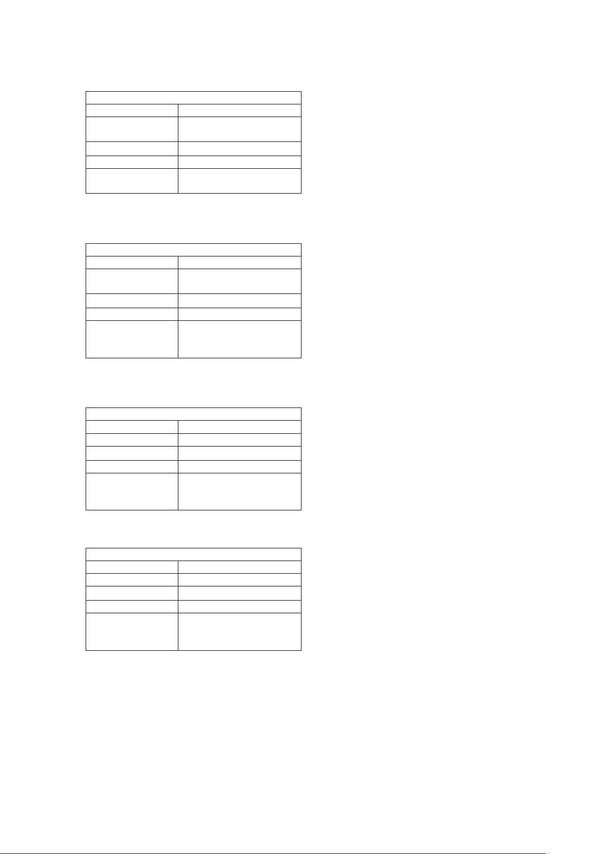
Status Code Facts
Number
13
Name
Corrupt or missing
application
Type
Normal
Group
Informational
LED Reporting
Rapid yellow, press feed
button shows off
Status Code Facts
Number
21
Name
Boot/Application version
mismatch
Type
Normal
Group
Informational
LED Reporting
Rapid yellow, press feed
yellow flash
Status Code Facts
Number
22
Name
Wrong target
Type
Normal
Group
Informational
LED Reporting
Rapid yellow, press feed
yellow
Status Code Facts
Number
23
Name
Tag system not found
Type
Normal
Group
Informational
LED Reporting
Rapid yellow, press feed
yellow
5.3.4 15 – Corrupt or missing application
This code is reported at startup when there
is no valid firmware application installed in
the flash.
It is cleared by a successful application load
operation.
5.3.5 21 – Bo ot/Application version mismatch
This code is reported at during a firmware
load attempt if this bootware cannot load it
because it is not compatible.
It is cleared by a successful load of a
compatible firmware file, or upgrading of
bootware which can o nly be done at a Zebra
button shows slower
service center.
5.3.6 22 – Wrong target
button shows solid
button shows solid
This code is reported during a firmware load
attempt if the firmware file is not intended
for the printer version it is sent to.
It is cleared by a successful application load
operation.
5.3.7 23 – Tag system not found
This code is reported at during a firmware
load attempt if either the file did not contain
a tag structure in its first two kilobytes, or
the bootware could not locate the hardware
tags in the printer.
It is cleared by a successful application load
operation.
P1066584-001 KR203 KPL Programming Manual Page 39 of 58
Page 40

“Status Protocol”
Setting
XML
1
Yes
Yes
Yes
Yes
Yes
Yes
Yes
Yes
TTP 0 No
Lim
Yes
Lim
Lim
Lim
Lim
Yes
6 Status Protocols
6.1 Status Protocol Over v i ew
The KR203 provides two options for status reporting format, either the XML format or the
legacy TTP format.
Not all protocols implement all status responses. Refer to the following table to see the
features of the protocols:
Protocol
Active designation
Send status
Send ack marker
Send information
Send Tags
Send Sensor
Send Parameter
Send all parameters
“Lim” in the above table means that only limited information is available in this protocol.
Active Designation
If a protocol supports this feature, the host will be able to designate the difference between
an actively reported “Send status” command, and one that was issued by the host. The only
active reporting that occurs in the KR203 is in the form of a “Send status” command.
6.2 XML Protocol
The XML protocol is the default reporting protocol of the KR203 printer, it is fully featured
and returns the maximum amount of information. The protocol returns complete XML
documents to the host for processing.
Protocol Streaming
When this protocol transmits data to the host, the printer does not form the entire buffer in
memory before transmitting it, rather it streams it to the host. For this reason it is very
important that once the host starts reading data that it continues. Once a read has started,
each streamed data packet has a “time to live”. If the packet is not retrieved within that time,
the packet dies.
Protocol Wrapping
In the XML protocol, if more than one status request (including an active status message) are
received close together (within 70ms), they are concatenated into a single XML document.
This can include messages of different types. The host will receive a different block for each
enquiry it must answer.
Information Level
In the XML protocol, the XML information level det ermines how much information is provided
with each response; the higher the number the more information is provided. The
information level can be set to 10 (minimum), 20 (medium), or 30 (maximum).
P1066584-001 KR203 KPL Programming Manual Page 40 of 58
Page 41

"Application"
The message is from the application.
"Boot"
The message is from the bootware.
6.2.1 Header
All communication from this protocol starts with the following XML header, stating the XML
version and character coding.
<?xml version=”1.0” encoding=“UTF-8” standalone=”yes” ?>
The header does not have an end element.
6.2.2 Root Element
The root element is reported in all XML documents and is as follows. It is marked as bold in
XML below.
<?xml version=”1.0” encoding=“UTF-8” standalone=”yes” ?>
<zebra-eltron-personality>
...
</zebra-eltron-personality>
6.2.2.1 Model Element This element is included in all communication and states the model of the printer sending the
XML data. It also includes one XML attribute named “module”. This specifies which piece of
printer software is sending the message. It is included with all responses at all information
levels.
<?xml version=”1.0” encoding=“UTF-8” standalone=”yes” ?>
<zebra-eltron-personality>
<model module=”Application”>KR203</model>
</zebra-eltron-personality>
6.2.2.2 Uptime element This element is included in all communication and tells the user how long the printer has been
powered up in this session. It is measured in the in printer clock ticks. The “Tick” field under
the “Send information” response tells you how many microseconds (µS) each tick represents.
<?xml version=”1.0” encoding=“UTF-8” standalone=”yes” ?>
<zebra-eltron-personality>
<model module=”Application”>KR203</model>
<uptime>412090</uptime>
</zebra-eltron-personality>
P1066584-001 KR203 KPL Programming Manual Page 41 of 58
Page 42

6.2.2.3 ID element This element is included in all communication and tells the user a unique number assigned to
each controller PCB. This is useful when processing messages from many printers.
<?xml version=”1.0” encoding=“UTF-8” standalone=”yes” ?>
<zebra-eltron-personality>
<model module=”Application”>KR203</model>
<uptime>412090</uptime>
<id> 432578253033553005D4FF32</id>
</zebra-eltron-personality>
6.2.2.4 Serial Number Element This element is included in all communication and tells the user a unique number assigned to
each printer frame. This is the same information that is printed on the serial number label of
the unit.
<?xml version=”1.0” encoding=“UTF-8” standalone=”yes” ?>
<zebra-eltron-personality>
<model module=”Application”>KR203</model>
<uptime>412090</uptime>
<id> 432578253033553005D4FF32</id>
<serial_number>96J101200003</serial_number>
</zebra-eltron-personality>
6.2.3 Send status block
One or more status codes can be transmitted in a single status block. The element is laid out
as follows.
Besides status codes, ack markers are also transmitted in the status block.
<?xml version=”1.0” encoding=“UTF-8” standalone=”yes” ?>
<zebra-eltron-personality>
<model module=”Application”>KR203</model>
<uptime>412090</uptime>
<id> 432578253033553005D4FF32</id>
<serial_number>96J101200003</serial_number>
<status>
<code value=”3” group=”1” />
<code value=”4” group=”1” />
</status>
</zebra-eltron-personality>
Type attribute
If the status block originates from active status reporting (not from an enquiry) it will have the
type attribute present, otherwise it will not.
...
<status type="active">
...
</status>
...
Additionally, the type may be designated as “keepalive”. This is status reported by the
automatic status reporting feature “Keepalive timeout”.
...
<status type="keepalive">
...
</status>
...
P1066584-001 KR203 KPL Programming Manual Page 42 of 58
Page 43

<code
Present in all levels
<timestamp
Present in information level 20 and higher
<name
Present in information level 20 and higher
The status block has the elements presented on the following tab le:
6.2.3.1 Code element The code element can be an empty element or a node element, depending on the information
level requested. The following example shows an information level 10 response, showing
status codes 3 and 4, as well as their group numbers. See “Status codes” for more
information on code numbers and groups.
<code value=”3” group=”1” />
<code value=”4” group=”1” />
6.2.3.1.1 Value
This field shows the status code number.
6.2.3.1.2 Group
This field shows the status’s group number.
6.2.3.2 Code child elements
When the information level is greater than 10, several child elements are also presented for
each code element.
6.2.3.2.1 Name
This represents the name of the status code being reported in English.
6.2.3.2.2 Timestamp
This represents the timestamp that the status code was set. It is relative to the “uptime”
element in the root of the XML document.
Both of these elements are shown below:
...
<status>
<code id="3" group="1">
<timestamp>9120</timestamp>
<name>Out of paper</name>
</code>
</status>
...
P1066584-001 KR203 KPL Programming Manual Page 43 of 58
Page 44

6.2.4 Send ack marker
One or more ack markers can be transmitted in a status block. The element is laid out as
follows.
<?xml version=”1.0” encoding=“UTF-8” standalone=”yes” ?>
<zebra-eltron-personality>
<model module=”Application”>KR203</model>
<uptime>412090</uptime>
<id> 432578253033553005D4FF32</id>
<serial_number>96J101200003</serial_number>
<status>
<ack_marker value = "1" />
</status>
</zebra-eltron-personality>
If an ack marker is removed from the buffer without all the commands preceding it having
executed, a negative ack marker can be received. This indicates that at least one command
before the ack marker was not executed and disposed of.
<?xml version=”1.0” encoding=“UTF-8” standalone=”yes” ?>
<zebra-eltron-personality>
<model module=”Application”>KR203</model>
<uptime>412090</uptime>
<id> 432578253033553005D4FF32</id>
<serial_number>96J101200003</serial_number>
<status>
<nak_marker value = "1" />
</status>
</zebra-eltron-personality>
Only one additional element is added at information levels greater than 10, timestamp.
6.2.4.1 Timestamp
This represents the timestamp that the ack marker was executed. It is relative to the “uptime”
element in the root of the XML document.
<?xml version=”1.0” encoding=“UTF-8” standalone=”yes” ?>
<zebra-eltron-personality>
<model module=”Application”>KR203</model>
<uptime>412090</uptime>
<id> 432578253033553005D4FF32</id>
<serial_number>96J101200003</serial_number>
<status>
<ack_marker value = "1">
<timestamp>17820</timestamp>
</ack_marker>
</status>
</zebra-eltron-personality>
P1066584-001 KR203 KPL Programming Manual Page 44 of 58
Page 45

"Application"
The version information is for the application.
"Boot"
The version information is for the bootware.
6.2.5 Send info r m ation
Send information returns information about the application and bootware installed in the
printer. The identity block always contains the same information regardless of information
level.
...
<identity>
<device_id>MFG:Zebra Technologies ;MDL:ZTC
KR203;CMD:KPL;CLS:PRINTER;DES:KR203 Kiosk Printer;</device_id>
<version module="Application">
<version_number>K69.1.1</version_number>
<protover>1</protover>
<major>1</major>
<minor>0</minor>
<service_pack />
<svnrevision>1858</svnrevision>
<sandbox />
<configuration>Application_Based_On_Tag</configuration>
<compile_date>May 18 2010</compile_date>
<compile_time>15:09:49</compile_time>
<compiler_version>5040002</compiler_version>
</version>
<version module="Boot">
<version_number>V49a</version_number>
<svnrevision>1855</svnrevision>
<sandbox />
<configuration>Boot</configuration>
<compile_date>May 18 2010</compile_date>
<compile_time>14:58:13</compile_time>
<compiler_version>5040002</compiler_version>
</version>
<tick>250</tick>
</identity>
...
6.2.5.1 Device ID element
The device ID contains the complete plug and play string for the printer.
6.2.5.2 Version element
The version element is an element which has child elements that contain version information.
It also includes one XML attribute named “module”. This specifies which piece of software
(bootware or application) this particular version element is reporting on. It is included with all
responses at all information levels.
If this element is empty as shown below, it indicates that the indicated software item is not
installed.
<version module="Boot" />
6.2.5.3 Version child elements
All version child elements are returned at all information levels, if they are returned at all.
P1066584-001 KR203 KPL Programming Manual Page 45 of 58
Page 46

Application_Based_On_Tag
This is normal release build.
Boot
This is a normal release bootware.
6.2.5.3.1 Version Number
The version number tag contains the complete version string of the specified file type.
<version_number>K69.1.1</version_number>
6.2.5.3.2 Service Pack
If this is a service pack release, this contains the service pack letter. If this release is not a
service pack, the element is empty. It does not appear in the bootware.
<service_pack />
Populated example:
<service_pack>A</service_pack>
6.2.5.3.3 Sandbox
This will appear as an empty element if the firmware was built with changes from the
committed SVN revision. It does not appear if the file is identical to the SVN version.
<sandbox />
6.2.5.3.4 Configuration
This element tells what configuration the build system was in when the file was built. This
information is present for both bootware and applications. The valid options are as follows:
<configuration>Application_Based_On_Tag</configuration>
6.2.5.3.5 Compiler Information
There are three elements that provide information about the compile date, compile time and
the version of the compiler.
<compile_date>May 18 2010</compile_date>
<compile_time>15:09:49</compile_time>
<compiler_version>5040002</compiler_version>
6.2.5.4 Tick Element
This element provides information about how many microseconds (µS) have elapsed for each
tick in an uptime value or timestamp value.
<tick>250</tick>
6.2.5.5 Additional Information Reported
At information level 20 and higher, a complete report of all the parameter settings is provided
for all trays, and also a status report.
At information level 30, stack debugging information is included.
P1066584-001 KR203 KPL Programming Manual Page 46 of 58
Page 47

<sensor
Present in all levels
<raw
Present in information level 20 and higher
<range
Present in information level 20 and higher
<thresh_min
Present in information level 20 and higher
<thresh_max
Present in information level 20 and higher
<name
Present in information level 20 a nd hig her
6.2.6 Send sensor
One or more sensors can be transmitted in a sensor block. The element is laid out as follows.
<?xml version="1.0" encoding="UTF-8" standalone="yes" ?>
<zebra-eltron-personality>
<model module="Application">KR203</model>
<uptime>10818</uptime>
<id> 432578253033553005D4FF32</id>
<serial_number>96J101200003</serial_number>
<sensors>
<sensor id="1" value="0" />
<sensor id="9" value="26" />
</sensors>
</zebra-eltron-personality>
The sensor block has the elements presented on the following table:
6.2.6.1 Sensor element The sensor element can be an empty element or a node element, depending on the
information level requested. The above example shows an information level 10 response,
showing sensors one and nine. See the “Send sensor” command for more information on
sensors.
6.2.6.1.1 ID
This field contains the ID number of the sensor being reported on.
6.2.6.1.2 Value
This contains the value of the sensor specified by the ID.
6.2.6.2 Sensor child elements
The following sensor child elements are available on all information levels over 10.
6.2.6.2.1 Raw Value
This element reports on the raw, unprocessed value of the sensor. This is an immediate
reading. The raw element has one attribute, bits, which contains the size, in bits, of the raw
value.
<raw bits="8">227</raw>
6.2.6.2.2 Range
This element expressed the range of the value element. It can contain both positive and
negative numbers. Individual values are separated by a comma, and ranges are signified with
two periods (..).
<range>0,1</range>
P1066584-001 KR203 KPL Programming Manual Page 47 of 58
Page 48

<parameter
Present in all levels
<default
Present in information level 20 and higher
<stored
Present in information level 20 and higher
<name
Present in information level 20 and higher
<size
Present in information level 20 and higher
<range
Present in information level 20 and higher
<attribute
Present in information level 20 and higher
6.2.6.2.3 Range
This element expressed the range of the value element. It can contain both positive and
negative numbers. Individual values are separated by a comma, and ranges are signified with
two periods (..).
<range>0,1</range>
6.2.6.2.4 Thresholds
For sensors that use thresholds (all A/D sen sors), this reports o n the high and low thresholds
for the specified sensor. In order to signal a change, the sensor must detect that it has
pushed beyond the threshold in the given direction that it is detecting.
<thresh_min>168</thresh_min>
<thresh_max>148</thresh_max>
For example, when these values, the raw value must move above 168 to trigger positive, or
below 148 to trigger negative. Values in the middle w ill not cause a state change.
6.2.6.2.5 Name
This represents the name of the sensor being reported on in English.
The following is an information level 30 example showing all elements.
<sensor id="1" value="0">
<raw bits="8">227</raw>
<range>0,1</range>
<thresh_min>168</thresh_min>
<thresh_max>148</thresh_max>
<name>End of paper selected</name>
</sensor>
6.2.7 Send parameter
One or more parameters can be transmitted in a parameter block. The element is laid out as
follows.
<?xml version="1.0" encoding="UTF-8" standalone="yes" ?>
<zebra-eltron-personality>
<model module="Application">KR203</model>
<uptime>10818</uptime>
<id> 432578253033553005D4FF32</id>
<serial_number>96J101200003</serial_number>
<parameters tray="0">
<parameter id="254" current="105988" />
<parameter id="48" current="0" />
</parameters>
</zebra-eltron-personality>
The parameter block has the elements presented on the following table:
P1066584-001 KR203 KPL Programming Manual Page 48 of 58
Page 49

6.2.7.1 Parameter element The parameter element can be an empty element or a node element, depending on the
information level requested. The above example shows an information level 10 response,
showing parameters 48 and 254. See the “Parameters” section for more information on
parameters.
6.2.7.1.1 ID
This field contains the ID number of the parameter being reported on.
6.2.7.1.2 Current
This field contains the current value of the parameter being reported on.
6.2.7.2 Parameter child elements
The following parameter child elements are available on all information levels over 10.
6.2.7.2.1 Default
This element contains the default value of the selected parameter. This is the same as
reading the parameter from tray 255.
<default>0</default>
6.2.7.2.2 Stored
This element contains the stored value of the selected parameter. This is the same as reading
the parameter from tray 1.
<stored>105836</stored>
6.2.7.2.3 Name
This represents the name of the parameter being reported on in English.
<name>Uptime (s)</name>
6.2.7.2.4 Size
This represents the size of the parameter in bytes. This is important to know because this is
how much data must be specified when setting the parameter.
<size>4</size>
6.2.7.2.5 Range
This element expressed the range of acceptable values for the parameter. It can contain both
positive and negative numbers. Individual values are separated by a comma, and ranges are
signified with two periods (..). If all values are valid, the range element is empty.
<range />
Non-empty example:
<range>0,20..80</range>
6.2.7.2.6 Attributes
P1066584-001 KR203 KPL Programming Manual Page 49 of 58
Page 50

This element has two child elements that provide information about the read and write state
of the parameter.
<attributes>
<read_only>false</read_only>
<write_protected>false</write_protected>
</attributes>
6.2.7.2.6.1 Read Only
This attribute contains “true” if the parameter is a read only parameter that cannot be set,
otherwise it contains “false”.
6.2.7.2.6.2 Write Protected
This attribute contains “true” if the parameter cannot currently be written to, otherwise it
contains “false”.
The following is a complete example of two parameters at information level 30.
<parameters tray="0">
<parameter id="254" current="107198">
<default>0</default>
<stored>105836</stored>
<name>Uptime (s)</name>
<size>4</size>
<range />
<attributes>
<read_only>true</read_only>
<write_protected>true</write_protected>
</attributes>
</parameter>
<parameter id="48" current="0">
<default>0</default>
<stored>0</stored>
<name>Print width</name>
<size>1</size>
<range>0,20..80</range>
<attributes>
<read_only>false</read_only>
<write_protected>false</write_protected>
</attributes>
</parameter>
</parameters>
6.2.8 Send all parameters
Send all parameters simply returns many single pa r ameter entries. No additional information
is provided.
P1066584-001 KR203 KPL Programming Manual Page 50 of 58
Page 51

6.3 TTP Protocol
The TTP protocol is designed to be easier t o handle than the XML protocol, but provides
substantially less information. It is primarily intended for backwards compatibility and for
systems that cannot process XML.
6.3.1 Send status
In this mode, the printer will return a binary <06> if there are no statuses to report, or a
<21> followed by a status code (which is the same as the status number). This
<21><code> pattern is repeated for each status.
6.3.2 Send ack marker
In this mode, the printer will return a single byte indicating the ack number that was
requested.
6.3.3 Send info r m ation
In this mode, the printer will return two bytes indicating the length to follow and the USB
plug and play string. For the KR203 this is:
MFG:Zebra Technologies ;MDL:ZTC KR203;CMD:KPL;CLS:PRINTER;DES:KR203
Kiosk Printer;
6.3.4 Send tags
In this protocol, the firmware retur ns one byte indicating the length of the data to follow and
then the product’s serial number as stored in the tag system.
6.3.5 Send sensor
In this protocol, the parameter n is ignored, and the firmware returns two bytes. The first
byte is always a null. The second byte will have bits 0 and 1 set if media is detected at the
selected EOP sensor. The second byte will have bits 2, 3, 4 if there is media at the presenter.
These responses mimic the virtual status command of the TTP 2000.
6.3.6 Send parameter
In this protocol, the printer will simply return one to four binary bytes specifying the value of
the requested parameter from MSB to LSB. The number of bytes received depends on the
parameter requested.
6.3.7 Send all parameters
This command returns all the available parameters in the following format:
One byte indicating the total number of parameter record entries to follow.
For each record:
• One byte indicating the parameter number
• One byte indicating the size of the value in bytes.
• The specified number of bytes which contains the current value of the specified
parameter.
P1066584-001 KR203 KPL Programming Manual Page 51 of 58
Page 52

7 Tutorials
7.1 Text on KR203
7.1.1 Introduction
This mini tutorial describes how to print text on a graphics printer like the Zebra KR 203 on
embedded systems not using a printer driver supplied by Zebra.
The description is general and does not give examples in any specific programming language
nor how to send data to the USB port.
7.1.2 Document Format
Data is represented in standard Zebra Toolbox format, which interprets data within < and >
symbols as binary data. Standard ASCII names such as <ESC> and <ENQ> are converted to
their equivalent binary values by Toolbox, additionally numbers such as <5> are sent directly
as binary data to the printer.
To type in binary data , add a leading B <B 10000001>.
To type in hex data , add a leading H <H 41>.
Anything not appearing in brackets, such as the & in <ESC>&<4> is sent directly as ASCII
text to the printer. See Toolbox help for more information. Toolbox version 1.70 and higher
must be used with the KR203 printer
7.1.3 Overview
This section describes how to print the text string: “Text Arial 12B”
The KR203 is host based and does not contain any fonts. Therefore it cannot receive text to
be printed and convert it to pixels inside the printer.
The application program must convert the text to a bitmap and add the commands for the
receipt to be generated.
The printer uses a very simple system; 0 means a white pixel and 1 means a black pixel. With
203 dpi we have 8 pixels per mm so one byte with FF will print a 1 mm wide and 1/8 mm
high line.
11111111 = ----11110000 = –
The print starts from the left edge of the print area, at the top of the paper. All print is in
portrait mode. For landscape, the text must be rotated before converting it to a bitmap in the
application.
P1066584-001 KR203 KPL Programming Manual Page 52 of 58
Page 53

7.1.4 Print graphics line
The command to print a pixel line is:
<ESC>s<n1><n2>..<nX>
n1 = Data Size in bytes
n2…nX = Data
n1 can be between 1 and 80. Any li ne for which less data than the current print width i s
specified, the remainder of the line will be filled with blank pixels.
Our example Text Arial 12B
Only takes up 27.5 mm so there is no need sending 80 bytes, 28 will do. Cropping the lines
from white data in the right edge of the paper saves transfer time and memory.
□■■■■■■■■■■■■■■■■■■ ■□□□□□□□□□□□□□□□□□ □□□□□□□□□□□□□□□□□□□ □□□□□□■□□□□□□□□□□□ □□□□□□□□□■■■■■■ ■□□□□□□□□□□□□□□□□□□ □□□□□□□■■■■■□□□□□□ □□□□□□□□□□□□□□□□□■ ■■■■□□□□□□□□□□□□□□□ □□□□□□■■■■□□□□□□□□ □□□□□■■■■■■□□□□ □□□□■■■■■■■■■■■■■■■ □□□□□□□□□
□■■■■■■■■■■■■■■■■■■ ■□□□□□□□□□□□□□□ □□□□□□□□□□□□□□□□□□ □□□□□□□□■■■□□□□□□□□ □□□□□□□□□□□□■■■■■■ ■□□□□□□□□□□□□□□□□□□ □□□□□□□■■■■■□□□□□□ □□□□□□□□□□□□□□□□□■ ■■■■□□□□□□□□ □□□□□□□□□□□□■■■■■□□ □□□□□□□□□■■■■■■ ■■■■□□□□□□■■■■■■■■ ■■■■■■■■■□□□□□□□
□■■■■■■■■■■■■■■■■■■ ■□□□□□□□□□□□□□□□□□ □□□□□□□□□□□□□□□□□□□ □□□■■■■□□□□□□□□ □□□□□□□□□□□■■■■■■■ ■■□□□□□□□□□□□□□ □□□□□□□□□□□■■■■■□□□ □□□□□□□□□□□□□□□□□□ □□■■■■■□□□□□□□□□□□□ □□□□□□□□■■■■■□□□□□ □□□□□■■■■■■■ ■■■■■□□□□□■■■■■■■■ ■■■■■■■■■■□□□□□□
□■■■■■■■■■■■■■■■■■■ ■□□□□□□□□□□□□□□□□□ □□□□□□□□□□□□□□□□□□□ □□■■■■■□□□□□□□□□□□ □□□□□□□□■■■■■■■ ■■□□□□□□□□□□□□□□□□□ □□□□□□□■■■■■□□□□□□ □□□□□□□□□□□□□□□□□■ ■■■■□□□□□□□□□□□□□□□ □□□■■■■■■■□□□□□□□□ □■■■■■■■■■■■■■□ □□□□■■■■■■■■■■■■■■■ ■■■□□□□□□
□□□□□□□□■■■■■□□□□□□ □□□□□□□□□□□□□□□□□□ □□□□□□□□□□□□□□□□□□□ □□■■■■■□□□□□□□□□□□ □□□□□□□□■■■■□■■ ■■□□□□□□□□□□□□□□□□□ □□□□□□□□□□□□□□□□□□ □□□□□□□□□□□□□□□□□■ ■■■■□□□□□□□□□□□□□□□ □□■■■■■■■■□□□□□□□□ □■■■■■□□□■■■■■■ □□□□■■■■■□□□□□□□□■■ ■■■■□□□□□
□□□□□□□□■■■■■□□□□□□ □□□□□□□□□□□□□□□□□□ □□□□□□□□□□□□□□□□□□□ □□■■■■■□□□□□□□□□□□ □□□□□□□■■■■■□■■ ■■■□□□□□□□□□□□□□□□□ □□□□□□□□□□□□□□□□□□ □□□□□□□□□□□□□□□□□■ ■■■■□□□□□□□□□□□□□□□ ■■■■■■■■■■□□□□□□□□ ■■■■■□□□□□■■■■■ □□□□■■■■■□□□□□□□□□■ ■■■■□□□□□
□□□□□□□□■■■■■□□□□□□ □□□□□■■■■■■■□□□□□□ □□■■■■■□□□□□■■■■■□□ ■■■■■■■■■■□□□□□□□□ □□□□□□□■■■■■□■■ ■■■□□□□□□□□□□□■■■■□ □■■■■□□■■■■■□□□□□□ □□■■■■■■■■□□□□□□□■ ■■■■□□□□□□□□□□□□□□■ ■■■■■■■■■■□□□□□□□□ ■■■■■□□□□□■■■■■ □□□□■■■■■□□□□□□□□□■ ■■■■□□□□□
□□□□□□□□■■■■■□□□□□□ □□□□■■■■■■■■■□□□□□ □□■■■■■□□□□□■■■■■□□ ■■■■■■■■■■□□□□□□□□ □□□□□□□■■■■□□□■ ■■■□□□□□□□□□□□■■■■□ ■■■■■■□■■■■■□□□□□□ ■■■■■■■■■■■□□□□□□■ ■■■■□□□□□□□□□□□□□□■ ■■■■□■■■■■□□□□□□□□ ■■■■■□□□□□■■■■■ □□□□■■■■■□□□□□□□□□■ ■■■■□□□□□
□□□□□□□□■■■■■□□□□□□ □□■■■■■■■■■■■■■□□□ □□□■■■■■□□□■■■■■□□□ ■■■■■■■■■■□□□□□□□□ □□□□□□■■■■■□□□■ ■■■■□□□□□□□□□□■■■■■ ■■■■■□□■■■■■□□□□□■ ■■■■■■■■■■■■□□□□□■ ■■■■□□□□□□□□□□□□□□■ ■■□□□■■■■■□□□□□□□□ □□□□□□□□□□■■■■■ □□□□■■■■■□□□□□□□□□■ ■■■■□□□□□
□□□□□□□□■■■■■□□□□□□ □□■■■■■■■■■■■■■□□□ □□□■■■■■□□□■■■■■□□□ ■■■■■■■■■■□□□□□□□□ □□□□□□■■■■■□□□■ ■■■■□□□□□□□□□□■■■■■ ■■■■■□□■■■■■□□□□□■ ■■■■■■■■■■■■■□□□□■ ■■■■□□□□□□□□□□□□□□■ □□□□□■■■■■□□□□□□□□ □□□□□□□□□■■■■■■ □□□□■■■■■□□□□□□□□■■ ■■■□□□□□□
□□□□□□□□■■■■■□□□□□□ □■■■■■■□□□■■■■■■□□ □□□□■■■■■□■■■■■□□□□ □□■■■■■□□□□□□□□□□□ □□□□□□■■■■■□□□■ ■■■■□□□□□□□□□□■■■■■ ■■■■■□□■■■■■□□□□■■ ■■■□□□□■■■■■■□□□□■ ■■■■□□□□□□□□□□□□□□□ □□□□□■■■■■□□□□□□□□ □□□□□□□□□■■■■■□ □□□□■■■■■■■■■■■■■■■ ■■□□□□□□□
□□□□□□□□■■■■■□□□□□□ □■■■■■□□□□□■■■■■□□ □□□□□■■■■□■■■■□□□□□ □□■■■■■□□□□□□□□□□□ □□□□□■■■■■□□□□□ ■■■■■□□□□□□□□□■■■■■ ■□□□□□□■■■■■□□□□□□ ■■□□□□□□■■■■■□□□□■ ■■■■□□□□□□□□□□□□□□□ □□□□□■■■■■□□□□□□□□ □□□□□□□□■■■■■■□ □□□□■■■■■■■■■■■■■■■ ■□□□□□□□□
□□□□□□□□■■■■■□□□□□□ ■■■■■□□□□□□□■■■■■□ □□□□□■■■■■■■■■□□□□□ □□■■■■■□□□□□□□□□□□ □□□□□■■■■■□□□□□ ■■■■■□□□□□□□□□■■■■■ ■□□□□□□■■■■■□□□□□□ □□□□□□□□■■■■■□□□□■ ■■■■□□□□□□□□□□□□□□□ □□□□□■■■■■□□□□□□□□ □□□□□□□■■■■■■□□ □□□□■■■■■■■■■■■■■■■ ■■□□□□□□□
□□□□□□□□■■■■■□□□□□□ ■■■■■□□□□□□□■■■■■□ □□□□□□■■■■■■■□□□□□□ □□■■■■■□□□□□□□□□□□ □□□□□■■■■■□□□□□ ■■■■■□□□□□□□□□■■■■■ □□□□□□□■■■■■□□□□□□ □□□□□□■■■■■■■□□□□■ ■■■■□□□□□□□□ □□□□□□□□□□□□■■■■■□□ □□□□□□□□□□□□■■■■■■ □□□□□□□■■■■■■■■ ■■■■■■■■■■□□□□□□
□□□□□□□□■■■■■□□□□□□ ■■■■■■■■■■■■■■■■■□ □□□□□□■■■■■■■□□□□□□ □□■■■■■□□□□□□□□□□□ □□□□■■■■■□□□□□□ □■■■■■□□□□□□□□■■■■■ □□□□□□□■■■■■□□□□□□ □□■■■■■■■■■■■□□□□■ ■■■■□□□□□□□□□□□□□□□ □□□□□■■■■■□□□□□ □□□□□□□□■■■■ ■■□□□□□□□□■■■■■□□□ □□□□□■■■■■■□□□□□
□□□□□□□□■■■■■□□□□□□ ■■■■■■■■■■■■■■■■■□ □□□□□□□■■■■■□□□□□□□ □□■■■■■□□□□□□□□□□□ □□□□■■■■■■■■■■■ ■■■■■■□□□□□□□□■■■■■ □□□□□□□■■■■■□□□□□■ ■■■■■■■■■■■■■□□□□■ ■■■■□□□□□□□□□□□□□□□ □□□□□■■■■■□□□□□□□□ □□□□■■■■■■□□□□□ □□□□■■■■■□□□□□□□□□■ ■■■■■□□□□
□□□□□□□□■■■■■□□□□□□ ■■■■■■■■■■■■■■■■■□ □□□□□□■■■■■■■□□□□□□ □□■■■■■□□□□□□□□□□□ □□□□■■■■■■■■■■■ ■■■■■■□□□□□□□□■■■■■ □□□□□□□■■■■■□□□□■■ ■■■■■■□□■■■■■□□□□■ ■■■■□□□□□□□□□□□□□□□ □□□□□■■■■■□□□□□□□□ □□□■■■■■■□□□□□□ □□□□■■■■■□□□□□□□□□□ ■■■■■□□□□
□□□□□□□□■■■■■□□□□□□ ■■■■■□□□□□□□□□□□□□ □□□□□■■■■■■■■■□□□□□ □□■■■■■□□□□□□□□□□□ □□□■■■■■■■■■■■■ ■■■■■■■□□□□□□□■■■■■ □□□□□□□■■■■■□□□■■■ ■■■□□□□□■■■■■□□□□■ ■■■■□□□□□□□□□□□□□□□ □□□□□■■■■■□□□□□□□□ □□■■■■■■□□□□□□□ □□□□■■■■■□□□□□□□□□□ ■■■■■□□□□
□□□□□□□□■■■■■□□□□□□ ■■■■■□□□□□□□□□□□□□ □□□□□■■■■■■■■■□ □□□□□□■■■■■□□□□□□□□ □□□□□□■■■■■■■■■■■■ ■■■■■■■□□□□□□□■■■■■ □□□□□□□■■■■■□□□ ■■■■■□□□□□□■■■■■□□ □□■■■■■□□□□□□□□□□□□ □□□□□□□□■■■■■□□□□□ □□□□□■■■■■□□□□□□□□ □□□□■■■■■□□□□□□□□□□ ■■■■■□□□□
□□□□□□□□■■■■■□□□□□□ □■■■■■□□□□□□□□□□□□ □□□□■■■■■□■■■■■□□□□ □□■■■■■□□□□□□□□□□□ □□□■■■■■□□□□ □□□□□■■■■■□□□□□□□■ ■■■■□□□□□□□■■■■■□□□ ■■■■■□□□□□□■■■■■□□ □□■■■■■□□□□□□□□□□□□ □□□□□□□□■■■■■□□□□□ □□□□■■■■■□□□□□□ □□□□□□□■■■■■□□□ □□□□□□□■■■■■□□□□
□□□□□□□□■■■■■□□□□□□ □■■■■■■□□□□■■■■□□□ □□□■■■■■■□■■■■■■□□□ □□■■■■■□□□□□□□□□□□ □□■■■■■■□□□□□□□ □□■■■■■■□□□□□□■■■■■ □□□□□□□■■■■■□□□ ■■■■■■□□□■■■■■■■□□ □□■■■■■□□□□□□□□ □□□□□□□□□□□□■■■■■□□ □□□□□□■■■■■■■■■■■■ ■■■□□□□■■■■■□□□□□□□ □□■■■■■□□□□□
□□□□□□□□■■■■■□□□□□□ □□■■■■■■■■■■■■■■■□ □□□■■■■■□□□■■■■■□□□ □□■■■■■■■■□□□□□□□□ □□■■■■■□□□□□□□□ □□□■■■■■□□□□□□■■■■■ □□□□□□□■■■■■□□□■■■ ■■■■■■■■■■■■■□□□□■ ■■■■□□□□□□□□□□□□□□□ □□□□□■■■■■□□□□□□□□ ■■■■■■■■■■■■■■■ □□□□■■■■■■■■■■■■■■■ ■■■■□□□□□
□□□□□□□□■■■■■□□□□□□ □□■■■■■■■■■■■■■■□□ □□■■■■■□□□□□■■■■■□□ □□■■■■■■■■□□□□□□□□ □□■■■■■□□□□□□□□ □□□■■■■■□□□□□□■■■■■ □□□□□□□■■■■■□□□□■■ ■■■■■■■■■■■■■□□□□■ ■■■■□□□□□□□□□□□□□□□ □□□□□■■■■■□□□□□□□□ ■■■■■■■■■■■■■■■ □□□□■■■■■■■■■■■■■■■ ■■■□□□□□□
□□□□□□□□■■■■■□□□□□□ □□□■■■■■■■■■■■■□□□ □■■■■■■□□□□□■■■■■■□ □□□■■■■■■■□□□□□□□□ □■■■■■■□□□□□□□□ □□□■■■■■■□□□□□■■■■■ □□□□□□□■■■■■□□□□□■ ■■■■■■■□□■■■■□□□□■ ■■■■□□□□□□□□□□□□□□□ □□□□□■■■■■□□□□□□□■ ■■■■■■■■■■■■■■■ □□□□■■■■■■■■■■■■■■■ ■■□□□□□□□
□□□□□□□□■■■■■□□□□□□ □□□□□■■■■■■■■□□□□□ □■■■■■□□□□□□□■■■■■□ □□□□■■■■■□□□□□□□□□ □■■■■■□□□□□□□□□ □□□□■■■■■□□□□□■■■■■ □□□□□□□■■■■■□□□□□□ ■■■■■□□□□■■■■■□□□■ ■■■■□□□□□□□□□□□□□□□ □□□□□■■■■■□□□□□□□■ ■■■■■■■■■■■■■■■ □□□□■■■■■■■■■■■■■■■ □□□□□□□□□
<ESC>s<27><B 011111111111111111110000000000000000000000000000000000000000001000000000000000000001111111000000000000000000000000011111000000000000000000000001111100000000000000000000011110000000000000111111000000001111111111111110>
<ESC>s<28><B 01111111111111111111000000000000000000000000000000000000000011100000000000000000000111111100000000000000000000000001111100000000000000000000000111110000000000000000000011111000000000001111111111000000111111111111111110000000>
<ESC>s<28><B 01111111111111111111000000000000000000000000000000000000000111100000000000000000001111111110000000000000000000000001111100000000000000000000000111110000000000000000000011111000000000011111111111100000111111111111111111000000>
<ESC>s<28><B 01111111111111111111000000000000000000000000000000000000001111100000000000000000001111111110000000000000000000000001111100000000000000000000000111110000000000000000001111111000000000111111111111100000111111111111111111000000>
<ESC>s<28><B 00000000111110000000000000000000000000000000000000000000001111100000000000000000001111011110000000000000000000000000000000000000000000000000000111110000000000000000011111111000000000111110001111110000111110000000011111100000>
<ESC>s<28><B 00000000111110000000000000000000000000000000000000000000001111100000000000000000011111011111000000000000000000000000000000000000000000000000000111110000000000000001111111111000000001111100000111110000111110000000001111100000>
<ESC>s<28><B 00000000111110000000000011111110000000011111000001111100111111111100000000000000011111011111000000000001111001111001111100000000111111110000000111110000000000000011111111111000000001111100000111110000111110000000001111100000>
<ESC>s<28><B 00000000111110000000000111111111000000011111000001111100111111111100000000000000011110001111000000000001111011111101111100000011111111111000000111110000000000000011111011111000000001111100000111110000111110000000001111100000>
<ESC>s<28><B 00000000111110000000011111111111110000001111100011111000111111111100000000000000111110001111100000000001111111111001111100000111111111111100000111110000000000000011100011111000000000000000000111110000111110000000001111100000>
<ESC>s<28><B 00000000111110000000011111111111110000001111100011111000111111111100000000000000111110001111100000000001111111111001111100000111111111111110000111110000000000000010000011111000000000000000001111110000111110000000011111000000>
<ESC>s<28><B 00000000111110000000111111000111111000000111110111110000001111100000000000000000111110001111100000000001111111111001111100001111100001111110000111110000000000000000000011111000000000000000001111100000111111111111111110000000>
<ESC>s<27><B 000000001111100000001111100000111110000000111101111000000011111000000000000000011111000001111100000000011111100000011111000000110000001111100001111100000000000000000000111110000000000000000111111000001111111111111111>
<ESC>s<28><B 00000000111110000001111100000001111100000011111111100000001111100000000000000001111100000111110000000001111110000001111100000000000000111110000111110000000000000000000011111000000000000000111111000000111111111111111110000000>
<ESC>s<28><B 00000000111110000001111100000001111100000001111111000000001111100000000000000001111100000111110000000001111100000001111100000000000011111110000111110000000000000000000011111000000000000001111110000000111111111111111111000000>
<ESC>s<28><B 00000000111110000001111111111111111100000001111111000000001111100000000000000011111000000011111000000001111100000001111100000000111111111110000111110000000000000000000011111000000000000011111100000000111110000000011111100000>
<ESC>s<28><B 00000000111110000001111111111111111100000000111110000000001111100000000000000011111111111111111000000001111100000001111100000111111111111110000111110000000000000000000011111000000000000111111000000000111110000000001111110000>
<ESC>s<28><B 00000000111110000001111111111111111100000001111111000000001111100000000000000011111111111111111000000001111100000001111100001111111100111110000111110000000000000000000011111000000000001111110000000000111110000000000111110000>
<ESC>s<28><B 00000000111110000001111100000000000000000011111111100000001111100000000000000111111111111111111100000001111100000001111100011111100000111110000111110000000000000000000011111000000000011111100000000000111110000000000111110000>
<ESC>s<28><B 00000000111110000001111100000000000000000011111111100000001111100000000000000111111111111111111100000001111100000001111100011111000000111110000111110000000000000000000011111000000000011111000000000000111110000000000111110000>
<ESC>s<28><B 00000000111110000000111110000000000000000111110111110000001111100000000000000111110000000001111100000001111100000001111100011111000000111110000111110000000000000000000011111000000000111110000000000000111110000000000111110000>
<ESC>s<28><B 00000000111110000000111111000011110000001111110111111000001111100000000000001111110000000001111110000001111100000001111100011111100011111110000111110000000000000000000011111000000001111111111111110000111110000000001111100000>
<ESC>s<28><B 00000000111110000000011111111111111100001111100011111000001111111100000000001111100000000000111110000001111100000001111100011111111111111110000111110000000000000000000011111000000001111111111111110000111111111111111111100000>
<ESC>s<28><B 00000000111110000000011111111111111000011111000001111100001111111100000000001111100000000000111110000001111100000001111100001111111111111110000111110000000000000000000011111000000001111111111111110000111111111111111111000000>
<ESC>s<28><B 00000000111110000000001111111111110000111111000001111110000111111100000000011111100000000000111111000001111100000001111100000111111110011110000111110000000000000000000011111000000011111111111111110000111111111111111110000000>
<ESC>s<27><B 000000001111100000000000111111110000001111100000001111100000111110000000000111110000000000000111110000011111000000011111000000111110000111110001111100000000000000000000111110000000111111111111111100001111111111111110>
<RS><255>
Making a bitmap out of this text will give a 224 x 25 pixels image like below:
Use 1 for black and 0 for white, add the ESC s command and line length to each line. The
resulting code is shown below.
Note that three of the lines are one byte shorter because they each had 8 trailing zeroes
which are unnece ssary to send.
The graphics block ends with <RS><255> which cuts and ejects the receipt when printed.
One can copy the above code and paste it into Toolbox for an example print out.
To print more lines of text on the receipt, add line spacing by jumping ahead one mm, then
send the next text line. The Feed forward command is ESC J n. Add <ESC>J<8> to get 1
mm feed:
<ESC>s<27><B 011111111111111111110000000000000000000000000000000000000000001000000000000000000001111111000000000000000000000000011111000000000000000000000001111100000000000000000000011110000000000000111111000000001111111111111110>
<ESC>s<28><B 01111111111111111111000000000000000000000000000000000000000011100000000000000000000111111100000000000000000000000001111100000000000000000000000111110000000000000000000011111000000000001111111111000000111111111111111110000000>
<ESC>s<28><B 01111111111111111111000000000000000000000000000000000000000111100000000000000000001111111110000000000000000000000001111100000000000000000000000111110000000000000000000011111000000000011111111111100000111111111111111111000000>
<ESC>s<28><B 01111111111111111111000000000000000000000000000000000000001111100000000000000000001111111110000000000000000000000001111100000000000000000000000111110000000000000000001111111000000000111111111111100000111111111111111111000000>
<ESC>s<28><B 00000000111110000000000000000000000000000000000000000000001111100000000000000000001111011110000000000000000000000000000000000000000000000000000111110000000000000000011111111000000000111110001111110000111110000000011111100000>
<ESC>s<28><B 00000000111110000000000000000000000000000000000000000000001111100000000000000000011111011111000000000000000000000000000000000000000000000000000111110000000000000001111111111000000001111100000111110000111110000000001111100000>
<ESC>s<28><B 00000000111110000000000011111110000000011111000001111100111111111100000000000000011111011111000000000001111001111001111100000000111111110000000111110000000000000011111111111000000001111100000111110000111110000000001111100000>
<ESC>s<28><B 00000000111110000000000111111111000000011111000001111100111111111100000000000000011110001111000000000001111011111101111100000011111111111000000111110000000000000011111011111000000001111100000111110000111110000000001111100000>
<ESC>s<28><B 00000000111110000000011111111111110000001111100011111000111111111100000000000000111110001111100000000001111111111001111100000111111111111100000111110000000000000011100011111000000000000000000111110000111110000000001111100000>
<ESC>s<28><B 00000000111110000000011111111111110000001111100011111000111111111100000000000000111110001111100000000001111111111001111100000111111111111110000111110000000000000010000011111000000000000000001111110000111110000000011111000000>
<ESC>s<28><B 00000000111110000000111111000111111000000111110111110000001111100000000000000000111110001111100000000001111111111001111100001111100001111110000111110000000000000000000011111000000000000000001111100000111111111111111110000000>
<ESC>s<27><B 000000001111100000001111100000111110000000111101111000000011111000000000000000011111000001111100000000011111100000011111000000110000001111100001111100000000000000000000111110000000000000000111111000001111111111111111>
<ESC>s<28><B 00000000111110000001111100000001111100000011111111100000001111100000000000000001111100000111110000000001111110000001111100000000000000111110000111110000000000000000000011111000000000000000111111000000111111111111111110000000>
<ESC>s<28><B 00000000111110000001111100000001111100000001111111000000001111100000000000000001111100000111110000000001111100000001111100000000000011111110000111110000000000000000000011111000000000000001111110000000111111111111111111000000>
<ESC>s<28><B 00000000111110000001111111111111111100000001111111000000001111100000000000000011111000000011111000000001111100000001111100000000111111111110000111110000000000000000000011111000000000000011111100000000111110000000011111100000>
<ESC>s<28><B 00000000111110000001111111111111111100000000111110000000001111100000000000000011111111111111111000000001111100000001111100000111111111111110000111110000000000000000000011111000000000000111111000000000111110000000001111110000>
<ESC>s<28><B 00000000111110000001111111111111111100000001111111000000001111100000000000000011111111111111111000000001111100000001111100001111111100111110000111110000000000000000000011111000000000001111110000000000111110000000000111110000>
<ESC>s<28><B 00000000111110000001111100000000000000000011111111100000001111100000000000000111111111111111111100000001111100000001111100011111100000111110000111110000000000000000000011111000000000011111100000000000111110000000000111110000>
<ESC>s<28><B 00000000111110000001111100000000000000000011111111100000001111100000000000000111111111111111111100000001111100000001111100011111000000111110000111110000000000000000000011111000000000011111000000000000111110000000000111110000>
<ESC>s<28><B 00000000111110000000111110000000000000000111110111110000001111100000000000000111110000000001111100000001111100000001111100011111000000111110000111110000000000000000000011111000000000111110000000000000111110000000000111110000>
<ESC>s<28><B 00000000111110000000111111000011110000001111110111111000001111100000000000001111110000000001111110000001111100000001111100011111100011111110000111110000000000000000000011111000000001111111111111110000111110000000001111100000>
<ESC>s<28><B 00000000111110000000011111111111111100001111100011111000001111111100000000001111100000000000111110000001111100000001111100011111111111111110000111110000000000000000000011111000000001111111111111110000111111111111111111100000>
<ESC>s<28><B 00000000111110000000011111111111111000011111000001111100001111111100000000001111100000000000111110000001111100000001111100001111111111111110000111110000000000000000000011111000000001111111111111110000111111111111111111000000>
<ESC>s<28><B 00000000111110000000001111111111110000111111000001111110000111111100000000011111100000000000111111000001111100000001111100000111111110011110000111110000000000000000000011111000000011111111111111110000111111111111111110000000>
<ESC>s<27><B 000000001111100000000000111111110000001111100000001111100000111110000000000111110000000000000111110000011111000000011111000000111110000111110001111100000000000000000000111110000000111111111111111100001111111111111110>
<ESC>J<8>
<ESC>s<2><B 0000011111111100>
<ESC>s<2><B 0000111111111110>
<ESC>s<3><B 001111111111111110000000>
<ESC>s<3><B 001110001110001110000000>
<ESC>s<3><B 011100000100000111000000>
<ESC>s<3><B 111100000100000111100000>
<ESC>s<3><B 111100000100000111100000>
<ESC>s<3><B 111110001110001111100000>
<ESC>s<3><B 111111111111111111100000>
<ESC>s<3><B 111111111111111111100000>
<ESC>s<3><B 111001111111110011100000>
<ESC>s<3><B 111001111111110011100000>
<ESC>s<3><B 111000111111100011100000>
<ESC>s<3><B 111000011111000011100000>
<ESC>s<3><B 011100000000000111000000>
<ESC>s<3><B 001110000000001110000000>
<ESC>s<3><B 001111000000011110000000>
<ESC>s<2><B 0000111110111110>
<ESC>s<2><B 0000011111111100>
<RS><255>
Only three commands are required to print text. Graphics and bar codes are done exactly the
same way; convert to bitmap and send with ESC s.
P1066584-001 KR203 KPL Programming Manual Page 53 of 58
Page 54

7.2 Status from KR203
7.2.1 Introduction
This section describes how to add status readouts when you print on the graphi cs printer
Zebra KR203 from embedded systems not using a printer driver supplied by Zebra. Please
read section 7.1 before continuing with this section.
The description is general and does not give examples in any specific programming language
nor how to send data to the USB port.
7.2.2 Document Format
Data is represented in standard Zebra Toolbox format, which interprets data within < and >
symbols as binary data. Standard ASCII names such as <ESC> and <ENQ> are converted to
their equivalent binary values by Toolbox, additionally numbers such as <5> are sent directly
as binary data to the printer.
To type in binary data , add a leading B <B 10000001>.
To type in hex data , add a leading H <H 41>.
Anything not appearing in brackets, such as the & in <ESC>&<4> is sent directly as ASCII
text to the printer. See Toolbox help for more information. Toolbox version 1.70 and higher
must be used with the KR203 printer.
7.2.3 Overview
This section builds on 7.1 and adds status commands . Simple status messages will be
created to illustrate polling.
Typical status requests:
Printer is ready before data is sent
Printout was successful after completion of commands
Customer has taken the receipt
The application might want to know if paper low is signaled. Or, if printing valuable vouchers,
that the part containing the bar code used for claiming the value is printed before continuing
with the rest of the printout.
7.2.4 Set up the printer
The command to set the printer to Poll Mode is:
<ESC>&p<65><0>
The command to set the printer to TTP Status Protocol:
<ESC>&p<66><0>
By default, the printer is in Verbal Mode, which will send status automatically when
something happens, and the replies will be sent as XML with a header allowing the reply will
be identifiable. Describing that protocol is not in the scope of this section.
The examples in this section use the above command string to specify the printer responses.
<ESC>&p<65><0><ESC>&p<66><0>
<ESC>s<27><B 011111111111111111110000000000000000000000000000000000000000001000000000000000000001111111000000000000000000000000011111000000000000000000000001111100000000000000000000011110000000000000111111000000001111111111111110>
<ESC>s<28><B 01111111111111111111000000000000000000000000000000000000000011100000000000000000000111111100000000000000000000000001111100000000000000000000000111110000000000000000000011111000000000001111111111000000111111111111111110000000>
<ESC>s<28><B 01111111111111111111000000000000000000000000000000000000000111100000000000000000001111111110000000000000000000000001111100000000000000000000000111110000000000000000000011111000000000011111111111100000111111111111111111000000>
<ESC>s<28><B 01111111111111111111000000000000000000000000000000000000001111100000000000000000001111111110000000000000000000000001111100000000000000000000000111110000000000000000001111111000000000111111111111100000111111111111111111000000>
<ESC>s<28><B 00000000111110000000000000000000000000000000000000000000001111100000000000000000001111011110000000000000000000000000000000000000000000000000000111110000000000000000011111111000000000111110001111110000111110000000011111100000>
<ESC>s<28><B 00000000111110000000000000000000000000000000000000000000001111100000000000000000011111011111000000000000000000000000000000000000000000000000000111110000000000000001111111111000000001111100000111110000111110000000001111100000>
<ESC>s<28><B 00000000111110000000000011111110000000011111000001111100111111111100000000000000011111011111000000000001111001111001111100000000111111110000000111110000000000000011111111111000000001111100000111110000111110000000001111100000>
<ESC>s<28><B 00000000111110000000000111111111000000011111000001111100111111111100000000000000011110001111000000000001111011111101111100000011111111111000000111110000000000000011111011111000000001111100000111110000111110000000001111100000>
<ESC>s<28><B 00000000111110000000011111111111110000001111100011111000111111111100000000000000111110001111100000000001111111111001111100000111111111111100000111110000000000000011100011111000000000000000000111110000111110000000001111100000>
<ESC>s<28><B 00000000111110000000011111111111110000001111100011111000111111111100000000000000111110001111100000000001111111111001111100000111111111111110000111110000000000000010000011111000000000000000001111110000111110000000011111000000>
<ESC>s<28><B 00000000111110000000111111000111111000000111110111110000001111100000000000000000111110001111100000000001111111111001111100001111100001111110000111110000000000000000000011111000000000000000001111100000111111111111111110000000>
<ESC>s<27><B 000000001111100000001111100000111110000000111101111000000011111000000000000000011111000001111100000000011111100000011111000000110000001111100001111100000000000000000000111110000000000000000111111000001111111111111111>
<ESC>s<28><B 00000000111110000001111100000001111100000011111111100000001111100000000000000001111100000111110000000001111110000001111100000000000000111110000111110000000000000000000011111000000000000000111111000000111111111111111110000000>
<ESC>s<28><B 00000000111110000001111100000001111100000001111111000000001111100000000000000001111100000111110000000001111100000001111100000000000011111110000111110000000000000000000011111000000000000001111110000000111111111111111111000000>
<ESC>s<28><B 00000000111110000001111111111111111100000001111111000000001111100000000000000011111000000011111000000001111100000001111100000000111111111110000111110000000000000000000011111000000000000011111100000000111110000000011111100000>
<ESC>s<28><B 00000000111110000001111111111111111100000000111110000000001111100000000000000011111111111111111000000001111100000001111100000111111111111110000111110000000000000000000011111000000000000111111000000000111110000000001111110000>
<ESC>s<28><B 00000000111110000001111111111111111100000001111111000000001111100000000000000011111111111111111000000001111100000001111100001111111100111110000111110000000000000000000011111000000000001111110000000000111110000000000111110000>
<ESC>s<28><B 00000000111110000001111100000000000000000011111111100000001111100000000000000111111111111111111100000001111100000001111100011111100000111110000111110000000000000000000011111000000000011111100000000000111110000000000111110000>
<ESC>s<28><B 00000000111110000001111100000000000000000011111111100000001111100000000000000111111111111111111100000001111100000001111100011111000000111110000111110000000000000000000011111000000000011111000000000000111110000000000111110000>
<ESC>s<28><B 00000000111110000000111110000000000000000111110111110000001111100000000000000111110000000001111100000001111100000001111100011111000000111110000111110000000000000000000011111000000000111110000000000000111110000000000111110000>
<ESC>s<28><B 00000000111110000000111111000011110000001111110111111000001111100000000000001111110000000001111110000001111100000001111100011111100011111110000111110000000000000000000011111000000001111111111111110000111110000000001111100000>
<ESC>s<28><B 00000000111110000000011111111111111100001111100011111000001111111100000000001111100000000000111110000001111100000001111100011111111111111110000111110000000000000000000011111000000001111111111111110000111111111111111111100000>
<ESC>s<28><B 00000000111110000000011111111111111000011111000001111100001111111100000000001111100000000000111110000001111100000001111100001111111111111110000111110000000000000000000011111000000001111111111111110000111111111111111111000000>
<ESC>s<28><B 00000000111110000000001111111111110000111111000001111110000111111100000000011111100000000000111111000001111100000001111100000111111110011110000111110000000000000000000011111000000011111111111111110000111111111111111110000000>
<ESC>s<27><B 000000001111100000000000111111110000001111100000001111100000111110000000000111110000000000000111110000011111000000011111000000111110000111110001111100000000000000000000111110000000111111111111111100001111111111111110>
<ESC>J<8>
<ESC>s<2><B 0000011111111100>
<ESC>s<2><B 0000111111111110>
<ESC>s<3><B 001111111111111110000000>
<ESC>s<3><B 001110001110001110000000>
<ESC>s<3><B 011100000100000111000000>
<ESC>s<3><B 111100000100000111100000>
<ESC>s<3><B 111100000100000111100000>
<ESC>s<3><B 111110001110001111100000>
<ESC>s<3><B 111111111111111111100000>
<ESC>s<3><B 111111111111111111100000>
<ESC>s<3><B 111001111111110011100000>
<ESC>s<3><B 111001111111110011100000>
<ESC>s<3><B 111000111111100011100000>
<ESC>s<3><B 111000011111000011100000>
<ESC>s<3><B 011100000000000111000000>
<ESC>s<3><B 001110000000001110000000>
<ESC>s<3><B 001111000000011110000000>
<ESC>s<2><B 0000111110111110>
<ESC>s<2><B 0000011111111100>
<RS><255>
P1066584-001 KR203 KPL Programming Manual Page 54 of 58
Page 55

Reply
Name
Type
Group
<ACK>
Ok
Normal
Informational
<NAK><1>
Paper jam in presenter
Normal
Severe
<NAK><2>
Cutter Jam
Normal
Severe
<NAK><4>
Printhead lifted
Normal
Severe
<NAK><3>
Out of paper
Normal
Severe
<NAK><5>
Paper feed error
Normal
Severe
<NAK><6>
Head temperature error
Normal
Severe auto-clear
<NAK><10>
Black mark not found
One-time
Informational
<NAK><11>
Black mark calibration error
One-time
Informational
<NAK><12>
Index error
One-time
Informational
<NAK><16>
Timeout Occurred
One-time
Informational
<NAK><18>
Out of range
One-time
Informational
<NAK><19>
Paper low
Normal
Warning
<NAK><20>
Media in presenter
Normal
Informational
<NAK><24>
Invalid operation
One-time
Informational
<NAK><26>
Target is read only
One-time
Informational
<NAK><40>
Printer entered USB bus
One-time
Informational
<NAK><41>
System calibration error
One-time
Informational
<NAK><42>
System calibration success
One-time
Informational
7.2.5 Send status – <ESC><ENQ><1>
TTP mode query table
If more than one error is present when the query is sent, more than one reply will be
received.
7.2.5.1 Programming Example, Status
The below example asks for status before and after the printout.
<ESC>&P<65><0><ESC>&P<66><0>
<ESC><ENQ><1>
<* The application should wait for the reply and if <ACK>, continue with
the print data or if <NAK><N> take appropriate actions>
<ESC>s<27><B 011111111111111111110000000000000000000000000000000000000000001000000000000000000001111111000000000000000000000000011111000000000000000000000001111100000000000000000000011110000000000000111111000000001111111111111110>
<ESC>s<28><B 01111111111111111111000000000000000000000000000000000000000011100000000000000000000111111100000000000000000000000001111100000000000000000000000111110000000000000000000011111000000000001111111111000000111111111111111110000000>
<ESC>s<28><B 01111111111111111111000000000000000000000000000000000000000111100000000000000000001111111110000000000000000000000001111100000000000000000000000111110000000000000000000011111000000000011111111111100000111111111111111111000000>
<ESC>s<28><B 01111111111111111111000000000000000000000000000000000000001111100000000000000000001111111110000000000000000000000001111100000000000000000000000111110000000000000000001111111000000000111111111111100000111111111111111111000000>
<ESC>s<28><B 00000000111110000000000000000000000000000000000000000000001111100000000000000000001111011110000000000000000000000000000000000000000000000000000111110000000000000000011111111000000000111110001111110000111110000000011111100000>
<ESC>s<28><B 00000000111110000000000000000000000000000000000000000000001111100000000000000000011111011111000000000000000000000000000000000000000000000000000111110000000000000001111111111000000001111100000111110000111110000000001111100000>
<ESC>s<28><B 00000000111110000000000011111110000000011111000001111100111111111100000000000000011111011111000000000001111001111001111100000000111111110000000111110000000000000011111111111000000001111100000111110000111110000000001111100000>
<ESC>s<28><B 00000000111110000000000111111111000000011111000001111100111111111100000000000000011110001111000000000001111011111101111100000011111111111000000111110000000000000011111011111000000001111100000111110000111110000000001111100000>
<ESC>s<28><B 00000000111110000000011111111111110000001111100011111000111111111100000000000000111110001111100000000001111111111001111100000111111111111100000111110000000000000011100011111000000000000000000111110000111110000000001111100000>
<ESC>s<28><B 00000000111110000000011111111111110000001111100011111000111111111100000000000000111110001111100000000001111111111001111100000111111111111110000111110000000000000010000011111000000000000000001111110000111110000000011111000000>
<ESC>s<28><B 00000000111110000000111111000111111000000111110111110000001111100000000000000000111110001111100000000001111111111001111100001111100001111110000111110000000000000000000011111000000000000000001111100000111111111111111110000000>
<ESC>s<27><B 000000001111100000001111100000111110000000111101111000000011111000000000000000011111000001111100000000011111100000011111000000110000001111100001111100000000000000000000111110000000000000000111111000001111111111111111>
<ESC>s<28><B 00000000111110000001111100000001111100000011111111100000001111100000000000000001111100000111110000000001111110000001111100000000000000111110000111110000000000000000000011111000000000000000111111000000111111111111111110000000>
<ESC>s<28><B 00000000111110000001111100000001111100000001111111000000001111100000000000000001111100000111110000000001111100000001111100000000000011111110000111110000000000000000000011111000000000000001111110000000111111111111111111000000>
<ESC>s<28><B 00000000111110000001111111111111111100000001111111000000001111100000000000000011111000000011111000000001111100000001111100000000111111111110000111110000000000000000000011111000000000000011111100000000111110000000011111100000>
<ESC>s<28><B 00000000111110000001111111111111111100000000111110000000001111100000000000000011111111111111111000000001111100000001111100000111111111111110000111110000000000000000000011111000000000000111111000000000111110000000001111110000>
<ESC>s<28><B 00000000111110000001111111111111111100000001111111000000001111100000000000000011111111111111111000000001111100000001111100001111111100111110000111110000000000000000000011111000000000001111110000000000111110000000000111110000>
<ESC>s<28><B 00000000111110000001111100000000000000000011111111100000001111100000000000000111111111111111111100000001111100000001111100011111100000111110000111110000000000000000000011111000000000011111100000000000111110000000000111110000>
<ESC>s<28><B 00000000111110000001111100000000000000000011111111100000001111100000000000000111111111111111111100000001111100000001111100011111000000111110000111110000000000000000000011111000000000011111000000000000111110000000000111110000>
<ESC>s<28><B 00000000111110000000111110000000000000000111110111110000001111100000000000000111110000000001111100000001111100000001111100011111000000111110000111110000000000000000000011111000000000111110000000000000111110000000000111110000>
<ESC>s<28><B 00000000111110000000111111000011110000001111110111111000001111100000000000001111110000000001111110000001111100000001111100011111100011111110000111110000000000000000000011111000000001111111111111110000111110000000001111100000>
<ESC>s<28><B 00000000111110000000011111111111111100001111100011111000001111111100000000001111100000000000111110000001111100000001111100011111111111111110000111110000000000000000000011111000000001111111111111110000111111111111111111100000>
<ESC>s<28><B 00000000111110000000011111111111111000011111000001111100001111111100000000001111100000000000111110000001111100000001111100001111111111111110000111110000000000000000000011111000000001111111111111110000111111111111111111000000>
<ESC>s<28><B 00000000111110000000001111111111110000111111000001111110000111111100000000011111100000000000111111000001111100000001111100000111111110011110000111110000000000000000000011111000000011111111111111110000111111111111111110000000>
<ESC>s<27><B 000000001111100000000000111111110000001111100000001111100000111110000000000111110000000000000111110000011111000000011111000000111110000111110001111100000000000000000000111110000000111111111111111100001111111111111110>
<ESC>J<8>
<ESC>s<2><B 0000011111111100>
<ESC>s<2><B 0000111111111110>
<ESC>s<3><B 001111111111111110000000>
<ESC>s<3><B 001110001110001110000000>
<ESC>s<3><B 011100000100000111000000>
<ESC>s<3><B 111100000100000111100000>
<ESC>s<3><B 111100000100000111100000>
<ESC>s<3><B 111110001110001111100000>
<ESC>s<3><B 111111111111111111100000>
<ESC>s<3><B 111111111111111111100000>
<ESC>s<3><B 111001111111110011100000>
<ESC>s<3><B 111001111111110011100000>
<ESC>s<3><B 111000111111100011100000>
<ESC>s<3><B 111000011111000011100000>
<ESC>s<3><B 011100000000000111000000>
<ESC>s<3><B 001110000000001110000000>
<ESC>s<3><B 001111000000011110000000>
<ESC>s<2><B 0000111110111110>
<ESC>s<2><B 0000011111111100>
<RS><255>
<* The application should wait until the printout is ready>
<ESC><ENQ><1>
<* The application should wait for the reply and if <NAK><20> everything is
OK (Paper in presenter)>
If everything is OK, the reply will be <ACK><NAK><20> (ACK showing that the printer is OK
before the printout and NAK 20 because the printed receipt is in the presenter).
If the reply starts with <NAK><20>, the previous customer left the receipt. Send an <ENQ>
to eject the media.
7.2.6 Send ACK marker – <ESC><ACK><N1>
This command is used for synchronization and instructs the printer to return an ack marker to
the host when all the commands in the command queue have been executed up to the point
P1066584-001 KR203 KPL Programming Manual Page 55 of 58
Page 56

at which the command was received. Executed means physically printed in the case of motor
or feed commands, not just received by the printer.
N1 specifies the marker number to return. To avoid misinterpretation of the reply it is good
practice to select a value th at does not correspond to any of the values returned by the Send
Status query explained above.
7.2.6.1 Programming Example, Status and Sync
This example adds an ACK marker with the value 240 (0xF0) after the print command so we
know when printing and presenting is ready so we can ask for status the second time.
Note: The example also includes grayed-out Toolbox code to wait for the status r eplies and
display messages based on them, and stops on error. Copy and Paste into Toolbox to try the
functions.
<ESC>&P<65><0><ESC>&P<66><0>
<ESC><ENQ><1>
<DECLARE @A>
<LOOP 20>
<SET @A (POLL 250)>
<IF (LEN @A)><IF (ISNOTEQUAL @A (ACK))><MSGBOX "NOT ready to
print"><STOP><ELSE><EXITLOOP><ENDIF><ENDIF>
<ENDLOOP>
<ESC>s<27><B 011111111111111111110000000000000000000000000000000000000000001000000000000000000001111111000000000000000000000000011111000000000000000000000001111100000000000000000000011110000000000000111111000000001111111111111110>
<ESC>s<28><B 01111111111111111111000000000000000000000000000000000000000011100000000000000000000111111100000000000000000000000001111100000000000000000000000111110000000000000000000011111000000000001111111111000000111111111111111110000000>
<ESC>s<28><B 01111111111111111111000000000000000000000000000000000000000111100000000000000000001111111110000000000000000000000001111100000000000000000000000111110000000000000000000011111000000000011111111111100000111111111111111111000000>
<ESC>s<28><B 01111111111111111111000000000000000000000000000000000000001111100000000000000000001111111110000000000000000000000001111100000000000000000000000111110000000000000000001111111000000000111111111111100000111111111111111111000000>
<ESC>s<28><B 00000000111110000000000000000000000000000000000000000000001111100000000000000000001111011110000000000000000000000000000000000000000000000000000111110000000000000000011111111000000000111110001111110000111110000000011111100000>
<ESC>s<28><B 00000000111110000000000000000000000000000000000000000000001111100000000000000000011111011111000000000000000000000000000000000000000000000000000111110000000000000001111111111000000001111100000111110000111110000000001111100000>
<ESC>s<28><B 00000000111110000000000011111110000000011111000001111100111111111100000000000000011111011111000000000001111001111001111100000000111111110000000111110000000000000011111111111000000001111100000111110000111110000000001111100000>
<ESC>s<28><B 00000000111110000000000111111111000000011111000001111100111111111100000000000000011110001111000000000001111011111101111100000011111111111000000111110000000000000011111011111000000001111100000111110000111110000000001111100000>
<ESC>s<28><B 00000000111110000000011111111111110000001111100011111000111111111100000000000000111110001111100000000001111111111001111100000111111111111100000111110000000000000011100011111000000000000000000111110000111110000000001111100000>
<ESC>s<28><B 00000000111110000000011111111111110000001111100011111000111111111100000000000000111110001111100000000001111111111001111100000111111111111110000111110000000000000010000011111000000000000000001111110000111110000000011111000000>
<ESC>s<28><B 00000000111110000000111111000111111000000111110111110000001111100000000000000000111110001111100000000001111111111001111100001111100001111110000111110000000000000000000011111000000000000000001111100000111111111111111110000000>
<ESC>s<27><B 000000001111100000001111100000111110000000111101111000000011111000000000000000011111000001111100000000011111100000011111000000110000001111100001111100000000000000000000111110000000000000000111111000001111111111111111>
<ESC>s<28><B 00000000111110000001111100000001111100000011111111100000001111100000000000000001111100000111110000000001111110000001111100000000000000111110000111110000000000000000000011111000000000000000111111000000111111111111111110000000>
<ESC>s<28><B 00000000111110000001111100000001111100000001111111000000001111100000000000000001111100000111110000000001111100000001111100000000000011111110000111110000000000000000000011111000000000000001111110000000111111111111111111000000>
<ESC>s<28><B 00000000111110000001111111111111111100000001111111000000001111100000000000000011111000000011111000000001111100000001111100000000111111111110000111110000000000000000000011111000000000000011111100000000111110000000011111100000>
<ESC>s<28><B 00000000111110000001111111111111111100000000111110000000001111100000000000000011111111111111111000000001111100000001111100000111111111111110000111110000000000000000000011111000000000000111111000000000111110000000001111110000>
<ESC>s<28><B 00000000111110000001111111111111111100000001111111000000001111100000000000000011111111111111111000000001111100000001111100001111111100111110000111110000000000000000000011111000000000001111110000000000111110000000000111110000>
<ESC>s<28><B 00000000111110000001111100000000000000000011111111100000001111100000000000000111111111111111111100000001111100000001111100011111100000111110000111110000000000000000000011111000000000011111100000000000111110000000000111110000>
<ESC>s<28><B 00000000111110000001111100000000000000000011111111100000001111100000000000000111111111111111111100000001111100000001111100011111000000111110000111110000000000000000000011111000000000011111000000000000111110000000000111110000>
<ESC>s<28><B 00000000111110000000111110000000000000000111110111110000001111100000000000000111110000000001111100000001111100000001111100011111000000111110000111110000000000000000000011111000000000111110000000000000111110000000000111110000>
<ESC>s<28><B 00000000111110000000111111000011110000001111110111111000001111100000000000001111110000000001111110000001111100000001111100011111100011111110000111110000000000000000000011111000000001111111111111110000111110000000001111100000>
<ESC>s<28><B 00000000111110000000011111111111111100001111100011111000001111111100000000001111100000000000111110000001111100000001111100011111111111111110000111110000000000000000000011111000000001111111111111110000111111111111111111100000>
<ESC>s<28><B 00000000111110000000011111111111111000011111000001111100001111111100000000001111100000000000111110000001111100000001111100001111111111111110000111110000000000000000000011111000000001111111111111110000111111111111111111000000>
<ESC>s<28><B 00000000111110000000001111111111110000111111000001111110000111111100000000011111100000000000111111000001111100000001111100000111111110011110000111110000000000000000000011111000000011111111111111110000111111111111111110000000>
<ESC>s<27><B 000000001111100000000000111111110000001111100000001111100000111110000000000111110000000000000111110000011111000000011111000000111110000111110001111100000000000000000000111110000000111111111111111100001111111111111110>
<ESC>J<8>
<ESC>s<2><B 0000011111111100>
<ESC>s<2><B 0000111111111110>
<ESC>s<3><B 001111111111111110000000>
<ESC>s<3><B 001110001110001110000000>
<ESC>s<3><B 011100000100000111000000>
<ESC>s<3><B 111100000100000111100000>
<ESC>s<3><B 111100000100000111100000>
<ESC>s<3><B 111110001110001111100000>
<ESC>s<3><B 111111111111111111100000>
<ESC>s<3><B 111111111111111111100000>
<ESC>s<3><B 111001111111110011100000>
<ESC>s<3><B 111001111111110011100000>
<ESC>s<3><B 111000111111100011100000>
<ESC>s<3><B 111000011111000011100000>
<ESC>s<3><B 011100000000000111000000>
<ESC>s<3><B 001110000000001110000000>
<ESC>s<3><B 001111000000011110000000>
<ESC>s<2><B 0000111110111110>
<ESC>s<2><B 0000011111111100>
<RS><255>
<ESC><ACK><240>
<DECLARE @B>
<LOOP 20>
<SET @B (POLL 250)>
<IF (LEN @B)><IF (ISNOTEQUAL @B (240))><MSGBOX "Wrong data
received."><STOP><ELSE><EXITLOOP><ENDIF><ENDIF>
<ENDLOOP
<ESC><ENQ><1>
<DECLARE @C>
<LOOP 20>
<SET @C (POLL 250)>
<IF (LEN @C)><IF (ISNOTEQUAL @C (SADD (NAK) 20))><MSGBOX "PRINTING
FAILED!"><STOP><ELSE><MSGBOX "Printed OK!"><EXITLOOP><ENDIF><ENDIF>
<ENDLOOP>
P1066584-001 KR203 KPL Programming Manual Page 56 of 58
Page 57

7.2.7 Mo nitoring when customer takes receipt
The easiest way to know when a receipt is taken is to temporarily switch back to verbal
status mode by adding <ESC>&P<65><3> after the last line in the previous example. In
verbal mode the printer will automatically send <ACK> when the customer removes the
printout, without the application having to poll for status indefinitely. When the <ACK> has
been received, switch back to poll mode again with <ESC>&P<65><0>.
Another option is to leave the printer in poll mode and poll repeatedly for a status change. A
polling interval of 250 ms is recommended for this prin ter.
7.2.8 Printing valuable vouchers
On some receipts, it is important to know if
an element of value has been imaged. For
example, a redemption voucher has printed
the barcode for the customer to redeem the
coupon.
Place the sensitive element in the first 75 mm
of the printout, and as close to the 75 mm
line as possible.
Stop after printing 75 mm and request status.
The leading edge of the printout has reached
the presenter sensor and the printer should
return <NAK><20> as reply indicating that
the sensor detects the paper and the printout
is of the correct length. This implies the
barcode was imaged and the remaining
receipt image can be printed.
A different reply should signify an error has
occurred during the imaging of the voucher.
It is recommended to issue an alert and shut
down the kiosk until the error can be cleared.
P1066584-001 KR203 KPL Programming Manual Page 57 of 58
Page 58

7.2.8.1 Programming overview, Voucher print
It is best to monitor the p rinter during feed commands of white space. Issue an <ESC>J <n>
command to feed forward.
One more command, <ESC>p which triggers printout
Graphics to print “Bonus Voucher”
<ESC>p
<ESC><ACK><240>
Wait for the retur n of the ack marker
<ESC><ENQ><1>
<ESC>J<n>
Graphics to print “With the value of”
<ESC>p
<ESC><ACK><240>
Wait for the return of the ack marker
<ESC><ENQ><1>
<ESC>J<n>
Graphics to print “€50”
<ESC>p
<ESC><ACK><240>
Wait for the return of the ack marker
<ESC><ENQ><1>
<ESC>J<n>
And so on until the receipt is completed.
There is no cut and paste code for this printout as it would be too long for this
document but the concept can be applied in the application programming.
7.2.9 Summary of commands used:
Cut and present media <RS><N1>
Eject media <ENQ>
Force print <ESC>p
Print graphics line <ESC>s<N1><N2>..<nX>
Send ack marker <ESC><ACK><N1>
Send status <ESC><ENQ><1>
Feed forward <ESC>J<N1>
Set parameter <ESC>&p<N1><N2>..<NX>
P1066584-001 KR203 KPL Programming Manual Page 58 of 58
 Loading...