


 SUNBEAR HEAVY EQUIPMENT
DL165 Skid Steer Loader
Owner's
and
Operator's
Manual
PUBLICATION NO. 16500
SEPTEMBER, 2009

SUNBEAR HEAVY EQUIPMENT LIABILTY WARRANTY
THE WARRANTY IS THE ONLY OBLIGATION OF SUNBEAR HEAVY EQUIPMENT OR A SUNBEAR HEAVY EQUIPMENT DEALER TO THE PURCHASER OR ANYONE ELSE CONCERNING A PRODUCT. IT'S USE OR PERFORMANCE OR ITS LOSS OF USE OR FAILURE TO PERFORM. NEITHER SUNBEAR HEAVY EQUIPMENT NOR A IMPLIED REPRESENTATION, WARRANTY OR AGREEMENT CONCERNING A PRODUCT, NEITHER SUNBEAR HEAVY EQUIPMENT NOR A SUNBEAR HEAVY EQUIPMENT DEALER HAVE MADE OR WILL MAKE ANY REPRESENTATION, WARRANTY OR AGREEMENT CONCERNING A PRODUCT'S MERCHANTABILITY OR OTHER QUALITY, IT'S SUITABILITY FOR PURCHASER'S PURPOSE (EVEN IF A PURCHASER HAS INFORMED SUNBEAR HEAVY EQUIPMENT OR A SUNBEAR HEAVY EQUIPMENT DEALER OF THAT PURPOSE), IT'S DURABILITY, PERFORMANCE OR OTHER CONDITION.
EVEN IF SUNBEAR HEAVY EQUIPMENT OR A SUNBEAR HEAVY EQUIPMENT DEALER WAS ADVISED OF THE POSSIBILITY OF SUCH LOSS, NEITHER SUNBEAR HEAVY EQUIPMENT NOR A SUNBEAR HEAVY EQUIPMENT DEALER WILL BE LIABLE TO PURCHASER OR ANYONE ELSE FOR ANY INDIRECT, INCIDENTAL CONSEQUENTIAL, PUNITIVE, ECONOMIC, COMMERCIAL, OR SPECIAL LOSS WHICH IN ANY WAY ASSOCIATED WITH A PRODUCT. THIS INCLUDES ANY LOSS OF USE OR NON-PERFORMANCE OF A PRODUCT, ANY REPLACEMENT RENTAL OR ACQUISITION COST, ANY LOSS OF REVENUE OR PROFITS, ANY FAILURE TO REALIZE EXPECTED SAVINGS, ANY INTEREST COSTS, ANY IMPAIRMENT OF OTHER PERSON.
PURCHASER MAY NOT ATTEMPT TO ENLARGE ITS RIGHTS UNDER THE WARRANTY BY MAKING CLAIM, FOR INEMNITY, FOR BREACH OF CONTRACT, FOR BREACH OF COLLATERAL WARRANTY, FOR A TORT (INCLUDING NEGLIGENCE, MISREPRESENTATION OR STRICT LIABILITY) OR BY CLAIMING ANY OTHER CAUSE OF ACTION.
THE WARRANTY IS A CONDITION OF SALE OF THE PRODUCT TO THE PURCHSER AND WILL THEREFORE APPLY EVEN IF THE PURCHASER ALLEGES THAT THERE IS A TOTAL FAILURE OF THE PRODUCT.
WARRANTY DELIVERY: TWO (2) YEARS 1000HOURS (FOR ONLY SAMPLES).
N.B. Read and practice your Sunbear Heavy Equipment operating and servicing instructions.
Failure to do this may void the warranty.
PUBLICATION NO. 16500
SEPTEMBER, 2009
INDEX
1.SAFETY PRECAUTIONS
2.CONTROLS
2. 1 |
Instrument Panel |
2. 2 |
Control Lever Handles |
2. 3 |
Seat and Seat Belt |
2. 4 |
Seat Bar |
2.5 Parking Brake
2.6 Throttle Control
2.7 Lift Arm Support
2.8 Steering Control
2.9 Auxiliary Controls
2.10 Liftarm Control
2.11 Quick - Tach
2.12 Electrical Panel
3.OPERATION
3.1 Starting Instructions
3.2 Operating Procedure
3.3 Filling From a Pile
3.4 Digging with a Bucket
3.5 Leveling and Backfilling
3.6 Auxiliary Hydraulics
3. 7 |
Lifting |
3. 8 |
Towing |
3.9 Securing and Transporting
3.10 Lowering Lift Arms
3.11 Accumulator
4.MAINTENANCE
4.1 Preventive Maintenance Service Schedule
4.2 Service Access
4.3 Daily Service Checks
4.4 50 Hour Service Check
4.5 250 Hour Service Check
4.6 Final Drive Maintenance
4.7 Hydraulic / Hydrostatic System Maintenance
4.8 Engine Maintenance
4.9 Air Cleaner Maintenance
4.10 Engine Cooling System
4.11 Electrical System
4.12 Tire Maintenance
4.13 Trouble Shooting
4.14 Hydraulic / Hydrostatic Circuit
4.15 Special Tools
5.SPECIFICATIONS
5.1 Loader Specifications
5. 2 |
Torque Specifications |
5. 3 |
Decals |
6.ATTACHMENTS AND BUCKETS
6. 1 SUNBEAR Approved Buckets and Attachments
FOREWORD
This book has been written to give the Owner / Operator necessary operating, servicing and preventative maintenance instructions on the loader.
Read this manual completely and know the loader before operating or servicing it. Do not do any service procedures that are not in the Operator•s manual.
Only service personnel that have had training in the service of this loader can do these service procedures.
Reference Information
Write the correct information for your loaders in the spaces below. Always use these numbers when referring to your loader.
Model No.
Serial No.
Dealer Name
Address
Phone
Throughout this manual the terms DANGER, WARNING and CAUTION are used to indicate the degree of hazard in terms of personal safety. These words will be used in conjunction with the Safety - Alert symbol, a triangle with an exclamation mark.
Throughout this manual, the term IMPORTANT is used
*To indicate that instructions are necessary before operating or servicing the loader.
*To show important procedures which must be followed to prevent damage to the loader or attachment.
This warning indicates an DANGER immediate hazard which
WILL result in severe personal injury or death.
This warning indicates WARNING hazards or unsafe
practices which COULD result in severe personal injury or death.
This warning indicates hazards or unsafe
CAUTION practices which COULD result in minor personal
injury or product or property damage.
Instructions are necessary before operating or servicing this machine. Read the operators manual and service decals on the
IMPORTANT loader. Follow warnings and instructions in this manual
when making repairs, adjustments or servicing. Check for correct operation after adjustments and repairs.
This notice shows IMPORTANT important procedures
which must be followed to prevent damage to the loader or attachment.

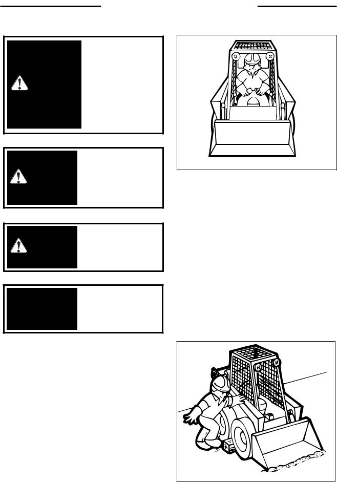
1. SAFETY PRECAUTIONS
The following precautions are suggested to help prevent accidents.
A careful operator is the best operator. Most accidents can be avoided by observing certain precautions. Read and take the following precautions before operating this loader to help prevent accidents. Equipment should be operated only by those who are responsible and instructed to do so.
1.Read this manual carefully before using the loader. Working with unfamiliar equipment can lead to accidents.
2.Do not allow anyone to ride on the loader with the operator.
3.Make sure the seat bar is installed and functioning at all times.
4.Never run the engine in a closed building without adequate ventilation, as the exhaust fumes can cause death.
5.Always fasten the seat belt around your waist before starting the engine. Never fasten the seat belt behind you.
6.Never attempt to start the engine while standing beside the unit unless as specified in this manual or under specific service and backhoe operation procedures. Start the engine only while sitting in the operator•s seat with the seat belt fastened around you. Always check to make certain that the seat cushion is secured to the frame.
7 Keep the operator•s area free of debris.
8.Never enter or leave the loader while the engine is running. Always lower the lift arms down against the frame, drop the attachment down to contact the ground, set the parking brake and shut off the engine prior to leaving the loader.
9.If the unit is equipped with a cab enclosure kit always close the door prior to operating the loader lift arms.
10.Do not operate the loader unless all safety equipment, shields, seat belt, seat bar, hydraulic controls, parking brake, operator guard, and lift arm support are working properly, as well as all safety and instruction decals are in place.
OPERATING THE LOADER
1.Always drive the loader at speeds compatible with safety, especially when operating over rough ground, crossing ditches or when turning.
2.Avoid jerky turns, starts, stops, or reverses.
3.Use care when operating on steep grades to maintain proper stability.
4.Do not turn the loader while the lift arms are in the raised position.
5.Be careful when driving through door openings or under overhead objects. Always make sure there is sufficient clearance for the operator•s guard.
6.When travelling on public roads, know the local rules and regulations and make sure your loader is equipped with the proper safety equipment.
7.Always be sure of water, gas, sewage and electrical line locations before you start to dig.
8.Watch out for overhead and underground high-voltage electrical lines when operating the loader.
9.Park the loader on level ground where possible. If the loader is to be parked on an incline, always lower the attachment so it contacts the ground, set the parking brake and block the wheels.
10.Do not leave the loader when it is in motion.
11.Do not dismount from the loader and leave the loader lift arms raised, unless following specific service procedures. Always lower the lift arms down against the frame and drop the attachment down to contact the ground.
12.Always be watchful of bystanders when operating the loader.
13.Always carry the attachment low for maximum stability and visibility.
14.Exercise extreme caution when operating the loader with a raised attachment.
15.Never attempt to lift loads in excess of loader capacity.
16.Check that control lever functions are locked before getting out of the operator•s seat.
17.Keep both hands on the control levers while the loader is in motion.
MAINTENANCE
1.Stop the engine before performing any service on the loader.
2.Never refuel the loader while smoking or with the engine hot or running.
3.Replace all missing, illegible or damaged safety and warning decals. See Section 5.3 for list.
4.Do not modify or alter, or permit anyone to modify or alter this loader or any of its components or any loader function.
5.Do not bypass the safety system. Consult your SUNBEAR Equipment Dealer if your safety controls are
malfunctioning.
6.Do not make mechanical adjustments while the loader is in motion or when the engine is running. However, if minor engine adjustments must be made, securely block the loader with the wheels clear of the ground, and use extreme caution.
7.Do not attempt to repair or tighten hydraulic hoses when the system is under pressure, when the engine is running or when the lift arms are raised.
8.Do not get under the attachment or lift arms or reach through the lift arms when they are raised.
9.Never attach the chains or ropes to the operator•s guard for pulling purposes, as the loader can tip over.
10.Whenever servicing or replacing pins in cylinder ends, buckets, etc., always use a brass drift and a hammer. Failure to do so could result in injury from flying metal fragments.
11.Cooling system operates under pressure which is controlled by the radiator cap. It is dangerous to remove the cap while system is hot. Always turn cap slowly to the first stop and allow the pressure to escape before removing the cap entirely.
12.Keep the operator area free from debris.
13.For lifting and towing instructions, refer to Sections 3.7 and 3.8 of this manual.
5
1. SAFETY PRECAUTIONS
To avoid personal injury, lower the lift arms, shut off the engine, raise the seat bar and cycle the hydraulics to ensure they are locked.
WARNING Then, unlatch the seat belt and exit the loader. Do not enter or exit with the engine running unless as specified
in this manual or under specific service and backhoe operating procedures.
To prevent personal injury do not operate the
WARNING loader without lowering the safety bar, fastening the seat belt and keeping
feet on the cab floor.
To prevent personal injury do not start the WARNING engine unless you are in the seat with the seat belt
fastened around you.
This engine is equipped IMPORTANT with glow plugs. Do not use ether or any high
energy fuels to assist starting.
C - 360
START SAFELY
1.Sit in the operator's seat and adjust it so you can operate all of the controls properly.
2.Adjust the seat and fasten the seat belt. Cycle the controls to make sure they are in the locked or neutral position. Lower the seat bar.
3.Know the exact starting procedure for your machine. See Section 3 for the manufacturer•s instructions for starting.
PARK SAFELY
Select level ground whenever possible. If you must park on a slope or incline, position the machine at right angles to the slope. Lower the attachment to the ground, engage the parking brake and block the wheels (C359).
C-359 |
6
2. CONTROLS
2.CONTROLS
2.1 Instrument Panel
2. 2 Control Lever Handles
2. 3 Seat and Seat Belt
2. 4 Seat Bar
2. 5 Parking Brake
2. 6 Throttle Control
2. 7 Lift Arm Support
2. 8 Steering Control
2. 9 Auxiliary Controls
2. 10 Liftarm Control
2. 11 Quick-Tach
2. 12 Electrical Panel
7
2. CONTROLS
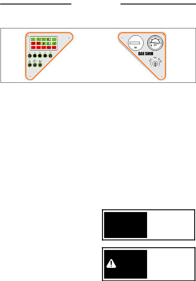
2.1INSTRUMENT PANEL
|
1 |
2 |
3 |
4 |
5 |
|
|
|
|
|
|
|
|
|
HOUR METER |
|
½ |
|
6 |
7 |
8 |
9 |
10 |
000032 H |
|
|
|
|
|
|
|
|
0 |
FULL |
|
|
11 |
12 |
13 |
14 |
15 |
1/10 |
|
|
|
|
|
|
|||||
|
|
|
|
|
|
21 |
|
22 |
|
16 |
|
|
17 |
|
|
|
|
18 |
19 |
20 |
|
|
|
|
|
23 |
|
|
|
|
|
|
|
|
K5250A
1.Left Signal Indicator Light: This light will illuminate when the operator uses the optional left signal. (Optional)
2.Auxiliary Front Indicator Light: This light will illuminate when the loader auxiliary hydraulic front switch is turned on. Light does not operate when lever switch is depressed.
3.Hi-Flow Hydraulics Indicator: This light will illuminate when the loader hi-flow hydraulics are in use. (Optional)
4.Work Lights (Up) Indicator: The light will illuminate when the loader work lights are turned on.
This will serve as a reminder to turn them OFF when the loader is not in use.
5.Right Signal Indicator Light: This light will illuminate when the operator uses the optional right signal. (Optional)
6.Hydraulic Oil Temperature Indicator: This light will illuminate when the oil temperature has exceeded recommended levels. Shut off the engine immediately and determine the cause.
7.Brake Light Indicator: The brake light will illuminate when the parking brake is engaged.
8.Seat Belt Indicator Light: This light will illuminate when the seat belt is unfastened.
9.Work Lights (Down) Indicator: The light will illuminate when the loader work lights are turned on.
This will serve as a reminder to turn them OFF when the loader is not in use.
10. Work Lights (Back) Indicator: This light will illuminate when the loader Back light are turned on. This
will serve as a reminer to turn them OFF when the loader is not in use.
11. Engine Oil Pressure Indicator: This light will illuminate when the engine loses lubrication pressure. Shut off the engine immediately and determine the cause.
12.Coolant Temperature Indicator Light: This light will illuminate if there is a rise in engine temperature. If this occurs, shut off the engine immediately and determine the cause.
13.Alternator Indicator Light: This light will illuminate when the alternator is not producing sufficient current.
14.Air Cleaner Indicator Light: This light will illuminate when there is an obstruction in the intake or when the air filter needs servicing. If this light illuminates, stop the engine and service the cleaner.
15.Pre-heat Indicator Light: This light will illuminate when the ignition key is turned counter clockwise to activate the engine glow plugs.
16. Headlight Switch: This is a toggle switch. Push up to turn the dipped beam lights on. These lights are located on the front of the loader.
17. Auxiliary Hydraulics Front Switch: This switch is a toggle switch. Push up to provide a continous flow of oil to the quick couplers when using an attachment.
This engine is equipped IMPORTANT with glow plugs. Do not use ether or any high
energy fuels to assist starting.
To prevent personal WARNING injury do not start the engine unless you are in the seat with the seat belt
fastened around you.
8

2. CONTROLS
Ensure liftarm brace is IMPORTANT properly stowed before raising or lowering lift
arms
18.Back Light Switch: This switch is a toggle switch Push up to turn the dipped beam lights on. This light are located on the rear of the loader.
19.Door Window Wiper Switch: This switch is a toggle switch. Push up to turn the wiper on.
20.Hi-Flow Hydraulic Switch: This switch is a toggle switch. Push up to turn the Hi-Flow hydraulics on. (Not available on all models)
21.Hour Meter: The hour meter records the number of engine operating hours and has a total of 99999.9 hours.
22.Fuel Gauge: The fuel gauge indicates the quantity of fuel remaining in the fuel tank.
23.Ignition Switch: The ignition switch is a three (3) position switch: 'OFF', 'ON', 'RUN' and 'START'. Turn the Turn the key counter clockwise to engage engine 'PREHEAT'. Turn the key clockwise to the 'START' position, this engages the starter The key will be in the 'RUN' position when released. Turn the key to 'OFF' to shut off the engine and remove the key.
2.2CONTROL LEVER HANDLES
LH Control Handle |
|
RH Control Handle |
|
|
1 |
|
6 |
3 |
2 |
5 |
8 |
|
|||
|
|
|
|
|
4 |
7 |
|
|
|
|
|
C3015 |
Fig. 2.2A |
C3933 |
Fig. 2.2B |
1.Spare
2.Spare
3, 4. Right / Left Direction Indicator (optional)
5.Horn
6.Spare
8.Auxiliary Hydraulic Switch
The left hand control lever is for moving the loader forward and reverse. Pushing the lever forward will cause the loader to move forward, and pulling the lever back towards the operator will cause the loader to move in reverse. This lever also operates hydraulic functions (refer to section 2.8 for instructions).
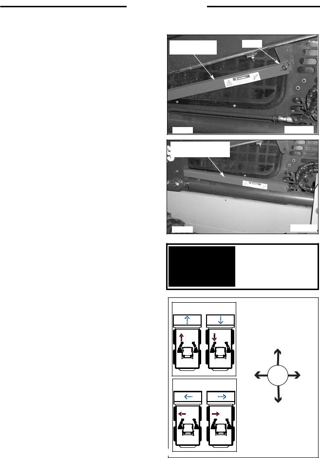
The right hand control lever controls the lift arms and bucket tilt. Pushing the lever forward will cause the lift arms to raise, while pulling the lever back towards the operator will cause the lift arms to lower. Moving the control lever to the left and right will tilt and untilt the bucket. Refer to section 2.10 for detailed operating instructions of this lever.
9

2. CONTROLS
2.3 SEAT AND SEAT BELT
The seat can be adjusted forward or back for operator comfort (Fig. 2.3A)
For your safety the loader is equipped with a seat belt. Before starting the loader adjust and fasten the seat belt (Fig. 2.3B) around you. The seat and seat belt also have integrated safety lock switches whereby the operator must be seated in the seat with the seat belt securely fastened and seat bar lowered before the loader hydraulics can be operated.
To prevent personal injury do not start the WARNING engine unless you are in the seat with the seat belt
fastened around you.
C2699 |
|
Fig. 2. 3A |
|
|
|
C2698 |
Release |
Fig. 2.3B |
10

2. CONTROLS
2. 4 |
SEAT BAR |
|
|
|
|
|
|
|
For operator protection the loader is equipped with a seat |
|
|
|
|
|
|
|
|
bar. |
|
|
|
|
|
|
|
|
The loader must be started with the operator seated in the |
|
|
|
|
|
|
|
|
loader and the seat bar in the up position. To raise the seat |
|
|
|
|
|
|
|
|
bar, lift up on the bar (Fig. 2.4A). In the up position, the |
|
|
|
|
|
|
|
|
|
|
|
|
|
|
|
||
seat bar activates the parking brake and locks out the |
|
|
|
|
|
|
|
|
|
|
|
|
|
|
|
||
functions of the control levers including the auxiliary |
|
|
|
|
|
|
|
|
|
|
|
|
|
|
|
||
hydraulics. |
|
|
|
|
|
|
|
|
|
|
|
|
|
|
|
||
When down (Fig. 2.4B), the seat bar releases the park |
|
|
|
|
|
|
|
|
|
|
Seat Bar Up |
|
|||||
brake and the hydraulic controls of the lift, tilt and |
|
|
|
|
|
|
|
|
|
|
|
|
|
|
|
||
auxiliary hydraulic circuits. |
|
|
|
|
|
|
|
|
C5295 |
|
|
|
|
Fig. 2. 4A |
|||
|
|
|
|
|
|
|||
|
|
|
|
|
|
|
|
|
Before exiting the loader always check the controls by cycling them to ensure that they are in the neutral position.
Seat Bar Down
|
To avoid personal injury, |
|
|
|
|
|
lower the lift arms, shut off |
|
|
|
|
|
the engine, raise the seat bar |
|
|
|
|
|
|
C5288 |
|
Fig. 2. 4B |
|
|
and cycle the hydraulics to |
|
|
||
WARNING |
ensure they are locked. Then, |
|
|
|
|
the loader. Do not enter or |
|
|
|
|
|
|
unlatch the seat belt and exit |
|
|
|
|
|
exit with the engine running |
|
|
|
|
|
unless as specified in this |
|
|
|
|
|
manual or under specific |
|
|
|
|
|
service and backhoe |
|
|
|
|
|
operating procedures. |
|
|
|
|
|
|
|
|
|
|
11
2. CONTROLS
2. 5 PARKING BRAKE
The loader is equipped with park brakes, located inside the torque motor. The brakes are activated and de-activated by the seat bar, via charge pressure. When the seat bar is in the up position, the brake is activated (Fig. 2.5A). When the seat bar is in the down position, the brake is off (Fig. 2.5B).
The loader has a parking brake indication light to warn that the brake is engaged. When the seat bar is in the down position, activation of the emergency break can be carried out by pushing on the button, located on the ROPS, in front of the left hand control lever handle.
2. 6 THROTTLE CONTROL
The diesel engine throttle control is located on the left hand side of the loader behind the control lever (Fig. 2.6). Engine start and stop are controlled electrically by the ignition key.
Before shutting off the engine, return the throttle control to idle position and allow the engine to cool at least 2 minutes.
Pushing the lever full forward increases the engine speed to maximum high idle. Pulling the lever back decreases the engine RPM.
The engine should always be operated at full speed and the loader travel speed controlled with the steering control lever (See Section 2.8).
To avoid personal injury, lower the lift arms, shut off the engine, raise the seat bar and cycle the hydraulics to ensure they are locked.
WARNING Then, unlatch the seat belt and exit the loader. Do not enter or exit with the engine running unless as specified
in this manual or under specific service and backhoe operating procedures.
Seat Bar Up
(Parking Brake on)
C5295 |
|
Fig. 2.5A |
|
|
|
Seat Bar Down
(Parking Brake off)
C3776 |
|
Fig. 2.5B |
|
|
|
High
Speed
Throttle
Control
Low
Speed
C5297 |
|
Fig. 2.6 |
|
|
|
12
2. CONTROLS
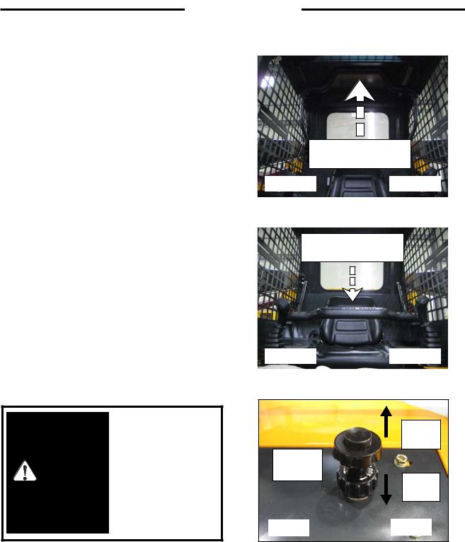
2. 7 LIFT ARM SUPPORT
For safety while performing regular service or maintenance work the loader is equipped with a liftarm support.
The liftarm support, when engaged, prevents the liftarms from dropping if hydraulic pressure is relieved or the right hand control lever is accidentally cycled.
To operate the liftarm support, remove attachment and park on level ground. Lower the liftarms to the ground and stop the engine. Exit the machine and remove pin that holds the liftarm support in stored positon(Fig. 2.7A). Lower the liftarm support to rest on the lift cylinder(Fig. 2.7B). Re-enter the machine and re-assume proper operating positon with the seat belt fastened and start the engine. Slowly raise the liftarms until the support falls onto the cylinder rod. Slowly lower the liftarms until support restricts movement. Stop the engine.
To remove the liftarm support, enter the loader and assume proper operating position with the seat belt fastened and start the engine, slowly raise the liftarms until the support is free, have a helper pin the support into its stored positon, lower the liftarms to the ground and shut off the engine before exiting the loader.
2. 8 STEERING CONTROL LEVER
The left control lever controls speed, direction and turning of the loader. Loader speed is controlled by the amount the lever is moved from the centre or neutral position. (Fig. 2.8A) The further away from neutral, the faster the travel speed. For maximum power and slow travel speed move the control lever only a small amount.
To drive the loader forward in a straight line, move the left control lever forward from the neutral position (Fig. 2.8A).
To drive the loader in reverse in a straight line, move the left control lever back from the neutral position (Fig. 2.8A).
The loader is turned by moving the left control lever to the side. To turn right while in forward or reverse travel, ease the control lever to the right. To stop turning, return the lever to a center position. To turn left while in forward or reverse travel, ease the lever to the left from the neutral position. To stop turning, return the lever to a center position (Fig. 2.8A).
For the loader to turn or "skid-steer" within its own length, move the lever to the left or the right from the neutral position. This causes the wheels on one side to turn forward and the wheels on the other side to reverse turning the loader (Fig. 2.8A).
Liftarm Support, |
Pin |
Stored Position |
|
C5298 |
Fig. 2.7A |
Liftarm Support
Resting On Cylinder
C 5299 |
Fig. 2. 7B |
Ensure liftarm brace is IMPORTANT properly stowed before raising or lowering lift
arms
Forward Reverse
|
|
Forward |
|
|
Left |
N |
Right |
|
Turn |
Turn |
|
Left Turn |
Right Turn |
|
|
|
|
Reverse |
|
C5415
C5416
Fig. 2.8A
13

2. CONTROLS
2.9ELECTRIC SOLENOID AUXILIARY CONTROLS
Auxiliary hydraulics (solenoid operated - standard) will only operate with the seat bar down.
A switch located on the R.H. steering control lever (Fig. 2.8A) is used to engage the loader's auxiliary hydraulic circuit to power attachments such as post hole augers, sweepers, etc. Pressing and holding the switch in position 1 (fig. 2.8A) provides hydraulic flow to the female quick connect coupling located at the front of the lift arms (fig. 2.8C). Releasing the switch returns the auxiliary hydraulic circuit to neutral, stopping the hydraulic flow.
Pressing and holding the switch in position 2 (fig. 2.8A) provides hydraulic flow to the male quick connect coupling located at the front of the lift arms (fig. 2.8C). releasing the switch returns the auxiliary hydraulic circuit to neutral, stopping hydraulic flow.
For continuous flow to the auxiliary hydraulic circuit, a toggle switch is located on the L.H. instrument panel (fig. 2.8B). Placing the switch in the "ON" position provides continuous hydraulic flow to the female quick connect coupling located at the front of the lift arms (fig. 2.8C). To stop hydraulic flow to the auxiliary hydraulic circuit, return the switch to the "OFF" position (fig. 2.8B). When the switch on the instrument panel is in the "ON" position, the switch located in the L.H. control lever is not operable.
NOTE: See Section 2.2 for information on the control handles.
To avoid personal injury, lower the lift arms, shut off the engine, raise the seat bar and cycle the controls to ensure they are locked.
WARNING Then, unlatch the seat belt and exit the loader. Do not enter or exit with the engine running unless as specified
in this manual or under specific service and backhoe operating procedures.
AUXILIARY HYDRAULIC CONTROL


 2
2
NEUTRAL
1
SEAT SIDE |
ROPS SIDE |
C5416 |
Fig. 2.9A |
TOGGLE
SWITCH
C5254 |
Fig. 2.9B |
|
Female Quick Coupling
Male Quick Coupling
C5255 |
Fig. 2.9C |
|
14

2. CONTROLS
2. 10 LIFTARM CONTROLS
The right hand control lever (Fig. 2.10) operates the loader•s liftarm and bucket hydraulic system. Refer to section 2.8 for instructions on steering control.
When the control lever is in the neutral position, the lift and tilt functions are static, the work attachment position should not change unless the control lever is moved. If the work attachment does move, service to hydraulic controls is required.
Having the control lever in the neutral position does not affect auxiliary hydraulics. Auxiliary hydraulics are controlled separately and will continue to operate with the control lever in the neutral position.
FLOAT (A)- Pushing the control lever all the way forward will lock the lever in liftarm float detent. This float position allows the work attachment to follow the contour of the ground. Lever will remain locked in float position until it is pulled out of float position.
LOWER (B)- To lower the liftarm, push the control lever straight forward from the neutral position, the control lever will return to the neutral position when released.
NEUTRAL (N)- Neutral (hold) position, lift and tilt functions are static. Liftarms should hold their position.
RAISE(D)- Pulling the control lever back from the neutral position will raise the liftarms, releasing the control lever will allow it to return to the neutral position.
TILT BACK (E)- Moving the control lever to the left will tilt the work attachment back (roll back bucket), releasing the control lever will allow it to return to a neutral position.
TILT FORWARD (F)- Moving the control lever to the right will tilt the work attachment forward (dump bucket), releasing the control lever will allow it to return to a neutral position.
By moving the control lever between two positons, both functions can be done at the same time.
- Move the lever diagonally between lower and tilt forward (B-F) to do both at the same time (lower and roll the work attachment forward).
-Move the lever diagonally between raise and tilt back (D- E) to do both at the same time (raise and roll the work attachment back).
To prevent personal injury do not operate the
WARNING loader without lowering the safety bar, fastening the seat belt and keeping
feet on the cab floor.
-Move the lever diagonally between raise and tilt forward (D-F) to do both at the same time (raise and tilt the work attachment forward).
-Move the lever diagonally between lower and tilt back (B-E) to do both at the same time (lower and tilt the work attachment back).
|
A |
|
|
B |
|
E |
N |
F |
|
D |
|
C5414 |
|
|
C5413 |
|
Fig. 2.10 |
C5325
To avoid personal injury, lower the lift arms, shut off the engine, raise the seat bar and cycle the hydraulics to ensure they are locked. Then unlatch
WARNING the seat belt and exit the loader. Do not enter or
exit with the engine running unless as specified in this manual or under specific service and backhoe operating procedures.
15
2. CONTROLS
2.11 QUICK - TACH
The quick-tach, which is standard equipment, allows changing from one attachment to another quickly without having to remove bolt or pins.
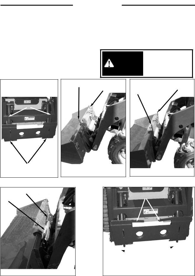
To operate, (Fig. 2.11A), lift the locking lever (1) up to completely retract the locking pins (2). Tilt the quick - tach frame forward (Fig. 2.11B) with the bucket tilt cylinders and drive into the attachment. Retract the bucket tilt cylinders (Fig. 2.11C) which will line up the bottom of the attachment with the quick - tach lock pins. Shut off the engine.
Push the locking lever (1) fully down (Fig. 2.11D) extending the lock pins (Fig. 2.11E item 2) through the attachment and securing the attachment.
Before operating the attachment check that the locking pins are correctly engaged.
After hooking up the WARNING attachment check to be sure pins and locking
levers are correctly engaged.
1 |
1 |
1 |
|
|
1 |
1
|
2 |
|
|
|
|
C5359 |
Fig. 2.11A |
C5410 |
Fig. 2.11B |
C5411 |
Fig. 2.11C |
1
1
1
 2
2 
C5412 |
Fig. 2.11D |
C 5357 |
Fig. 2.11E |
16
2. CONTROLS
2.12 ELECTRICAL PANEL |
|
|
||
The loader is equipped with a 12 volt, negative ground |
|
|
||
electrical system. The fuse and relay panel is located in the |
FUSE PANEL (3) |
|||
engine compartment on the underside of the engine cover. |
||||
6. |
Rear Lamp. (10A) |
|||
The panel consists of the following(Fig.2.12): |
||||
1. |
Engine Pre-Heater Relay. |
7. |
Wiper (15A)(Optional) |
|
2. |
Starter Relay. |
8. |
Back up Alram. (10A) |
|
3. |
Fuse Panel. |
9. |
Front Horn. (10A) |
|
4. |
Turn Signal Flasher (optional) |
10. |
Cigar Jack. (15A) |
|
5. |
Head Lamp. (20A) |
11. Aux, Hyd, Solenoid. (10A) |
||
|
|
12. |
Alternator Light. (10A) |
|
|
|
13. Brake Valve Solenoid. (10A) |
||
|
|
14. |
Shut Down. (15A) |
|
C5256
Fig 2.12
17

3. OPERATION
3.OPERATION
3.1 Starting Instructions
1.Pre-Starting Inspection
2.Starting Procedure
3.Shut-Off Procedure
3. 2 Operating Procedures
3. 3 Filling From a Pile
3. 4 Digging With a Bucket
3. 5 Leveling and Backfilling
3. 6 Auxiliary Hydraulics
3. 7 Lifting
3. 8 Towing
3. 9 Securing and Transporting
3. 10 Lowering Lift Arms
3. 11 Accumulator
18
3. OPERATION
3.1STARTING INSTRUCTIONS
1. Pre-Starting Inspection
Before starting the loader complete the following inspection:
(1)Check the hydraulic oil level, engine oil level, engine coolant level and fuel supply.
(2)Check for fuel, oil and hydraulic leaks.
(3)Check lights, battery level and cables.
(4)Check tire pressure:
10.00x 16.5 . . . . 40 - 45 PSI (276 - 310 kPa)
(5)Check wheel nut torque 100 - 110 ft. lbs. (13.8 - 15.2 kgm) (136149 Nm).
(6)Lubricate all grease fittings.
(7)Check the condition and operation of all safety decals and equipment … Ensure all shields and safety screens are in place. If necessary repair or replace before starting.
For complete daily servicing refer to section 4. 3.
To prevent personal injury do not operate the loader without lowering
WARNING the safety bar, fastening the seat belt and keeping
feet on the cab floor.
This engine is equipped IMPORTANT with glow plugs. Do not use ether or any high
energy fuels to assist starting.
To avoid personal injury do not start the engine unless you are in the seat
WARNING with the seat belt fastened around you,
unless as specified in this manual or under specific service and backhoe operating procedures.
5.Turn the key clockwise to start position to engage the starter. Do not crank the starter for more than 30 seconds. If the engine fails to start turn the key to off position, wait one minute, and repeat the procedure. If engine does not start after three attempts, check the fuel suppply system. The absence of blue or white smoke during cranking indicates that no fuel is being delivered.
6.When the engine has started the engine oil pressure and alternator warning lights should go out. If they don' t, shut - off the engine immediately and determine cause.
7.Allow the engine to warm up for five minutes before operating. When ready to operate, lower the seat bar and advance the throttle to full on position.
2. Starting Procedure
1.Ensure the seat bar is in the UP position and the control levers are in neutral.
2.Adjust and fasten the seat belt securely around you.
3.Place the throttle control in idle position.
4.Turn the ignition key counter clockwise to activate the glow plugs. Both the alternator and engine oil pressure warning lights should be on. Use chart for correct preheat times.
Glow Plug Pre-Heat Times
Ambient Temperature |
Preheat Time |
|
0 |
C(32 F) and Above |
10 Seconds |
-18 C(0 F) to 0 C(32 F) |
30 Seconds |
|
-23 |
C(-10F) to -18C(0 F) |
60 Seconds |
-29 C(-20 F) to -23 C(-10 F) |
120 Seconds |
|
Limit preheating to IMPORTANT recommended preheat
times; longer periods can ruin the glow plugs.
Overvoltage (14 volts or greater) will immediately destroy the glow plugs. Do not apply overvoltage to the starting circuit at
IMPORTANT any time. If boosting, use a battery of equal voltage to the loader and
connect it in parallel,positive to positive, negative to negative.
19

3. OPERATION
To avoid personal injury, lower the lift arms, shut off the engine, raise the seat bar and cycle the hydraulic controls to ensure they are
WARNING locked. Then, unlatch the seat belt and exit the loader. Do not enter or exit with the engine running unless as specified in this manual or under specific service and
backhoe operating procedures.
3. Shut-Off Procedure
|
Handle |
C5363 |
Fig. 3.3 |
(1)Select level ground whenever possible. If you must park on a slope or incline, position the machine at right angles to the slope. Lower the attachment to the ground, engage the parking brake and bloke the wheels.
(2)Lower the lift arms and ground the attachment.
(3)Return auxiliary hydraulics to neutral or OFF position.
(4)Return the throttle control to idle position. If the engine is hot allow it to idle until normal, at least 2 minutes.
(5)Never enter or exit the loader when the engine is running.
(6)Raise the seat bar to apply the park brake. Turn the ignition switch to the OFF position, remove the key, unfasten the seat belt, and ensure the hydraulic controls are locked by rocking them.
3. 2 OPERATING PROCEDURES
1.When learning to use the loader, operate at a slow rate.
2.Take advantage of the efficient operation of the loader. Keep the travel distance as short as possible. Keep the work area small so the cycle time is short.
3.Keep the work area as level as possible.
4.Decrease cycle time by "Skid" turning (See Section 2.8A) rather than a go backward-go forward turn.
5.Fill the bucket to rated capacity. Turning is easier with a full load than with a partial load. Keep the loaded bucket close to the ground when transporting.
6.Tilt the bucket as you raise the lift arms or drive up a slope. This will prevent material from falling off the back of the bucket.
7.Do not drive across a slope. Always go up or down a slope with the heavy end of the loader pointing up towards the top of the slope.
20

3. OPERATION
3. 3 FILLING FROM A PILE
Fig. 3.3A--Push ahead on the right hand control lever (1) and lower the lift arms completely down. Push to the right on the right hand control lever (2) and place the cutting edge of the bucket on the ground.
Fig. 3.3B--Push ahead on left hand lever to drive the loader forward slowly into the pile. As the bucket begins to fill pull to the left on the right hand lever (3) to raise the front of the bucket and pull back on the right hand lever (4) to raise the lift arms. When the bucket is full back away from the pile.
Fig. 3.3C--To dump the bucket pull back on the right hand control lever (4) to raise the lift arms, push to the right small amounts as the lift arms are raising to stop material from falling off the back of the bucket. When the bucket is at the correct height for dumping, push to the right on the right hand lever (2) to empty the bucket.
Always let the engine IMPORTANT warm completely before
you begin operation each day.
1
 2
2
C5303 |
Fig. 3.3A |
3 |
|
|
4 |
C5304 |
Fig. 3.3B |
|
2 |
4 |
|
C5305 |
Fig. 3.3C |
21

3. OPERATION
3. 4 DIGGING WITH A BUCKET
Fig. 3.4D--Push ahead on the right hand control lever (1) and lower the lift arms completely down. Push to the right on the right hand lever (2) and place the cutting edge of the bucket on the ground. Drive the loader forward at a slow rate and continue to tilt the bucket down until it enters the ground.
Fig. 3.4E--Pull to the left on the right hand lever (3) to raise bucket edge to increase traction and keep an even digging depth.
Fig. 3.4F--Continue to drive forward until the bucket is full. When digging in hard ground, it is easier to raise (3) and lower (2) the bucket cutting edge with the right hand control lever while slowly driving forward. When the bucket is full, pull to the left on the right hand control lever (3) to roll back the bucket.
1 |
|
|
2 |
C5306 |
Fig. 3.4D |
3 |
|
|
|
C5307 |
Fig. 3.4E |
|
To prevent personal |
|
|
WARNING |
injury, ensure that the |
|
|
rated capacity is being |
|
|
|
|
bucket with the proper |
|
|
|
used for the job you are |
3 |
2 |
|
doing. |
|
|
|
To avoid personal injury: |
|
|
|
When starting or |
|
|
WARNING |
operating loader in an |
|
|
enclosed area make sure |
|
|
|
|
there is enough |
|
|
|
ventilation. Exhaust |
|
|
|
fumes can kill. |
|
|
WARNING |
To prevent personal |
C5308 |
Fig. 3. 4F |
injury always carry the |
|
|
|
|
load low. |
|
|
22
 Loading...