

Page 1
IQ SENSOR NET
Power
!
O
K
MIQ/JB
Operating Manual
ba76030e01 01/2012
IQ SENSOR NET Branching module
Page 2

MIQ/JB
Note
For the most recent version of the manual, please visit www.ysi.com
.
Contact YSI
1725 Brannum Lane
Yellow Springs, OH 45387 USA
Tel: +1 937-767-7241
800-765-4974
Email: environmental@ysi.com
Internet: www.ysi.com
Copyright © 2012 Xylem Inc.
2
ba76030e01 01/2012
Page 3

MIQ/JB List of contents
MIQ/JB - List of contents
1 Overview . . . . . . . . . . . . . . . . . . . . . . . . . . . . . . . . . . . . 1-1
1.1 How to use this component operating manual . . . . . . . .1-1
1.2 Feature s of the MIQ/JB . . . . . . . . . . . . . . . . . . . . . . . . . 1-2
2 Safety instructions . . . . . . . . . . . . . . . . . . . . . . . . . . . . 2-1
2.1 Authorized use . . . . . . . . . . . . . . . . . . . . . . . . . . . . . . . .2-1
2.2 General safety instructions . . . . . . . . . . . . . . . . . . . . . . .2-2
3 Installation . . . . . . . . . . . . . . . . . . . . . . . . . . . . . . . . . . 3-1
3.1 Scope o f de livery . . . . . . . . . . . . . . . . . . . . . . . . . . . . . .3-1
3.2 Installation in the IQ S
ENSOR NET . . . . . . . . . . . . . . . . . 3-1
4 Maintenance and cleaning . . . . . . . . . . . . . . . . . . . . . 4-1
4.1 Maintenance . . . . . . . . . . . . . . . . . . . . . . . . . . . . . . . . . .4-1
4.2 Cleaning . . . . . . . . . . . . . . . . . . . . . . . . . . . . . . . . . . . . .4-1
5 Technical data . . . . . . . . . . . . . . . . . . . . . . . . . . . . . . . 5-1
6 Contact Information . . . . . . . . . . . . . . . . . . . . . . . . . . . 6-1
6.1 Ordering & Technical Support . . . . . . . . . . . . . . . . . . . . 6-1
6.2 Service In fo rmation . . . . . . . . . . . . . . . . . . . . . . . . . . . . 6-1
ba76030d01 01/2012
0 - 1
Page 4

List of contents MIQ/JB
0 - 2
ba76030d01 01/2012
Page 5
MIQ/JB Overview
IQ Sensor Net Operating Manual
System
Operating
Manual
(Ring Binder)
IQ Sensor
Operating
Manual
MIQ Module
Operating
Manual
MIQ Terminal
Operating
Manual
Component Operating Manuals
1Overview
1.1 How to use this component operating manual
Structure of the
IQ S
ENSOR NET
operating manual
ba76030e01 01/2012
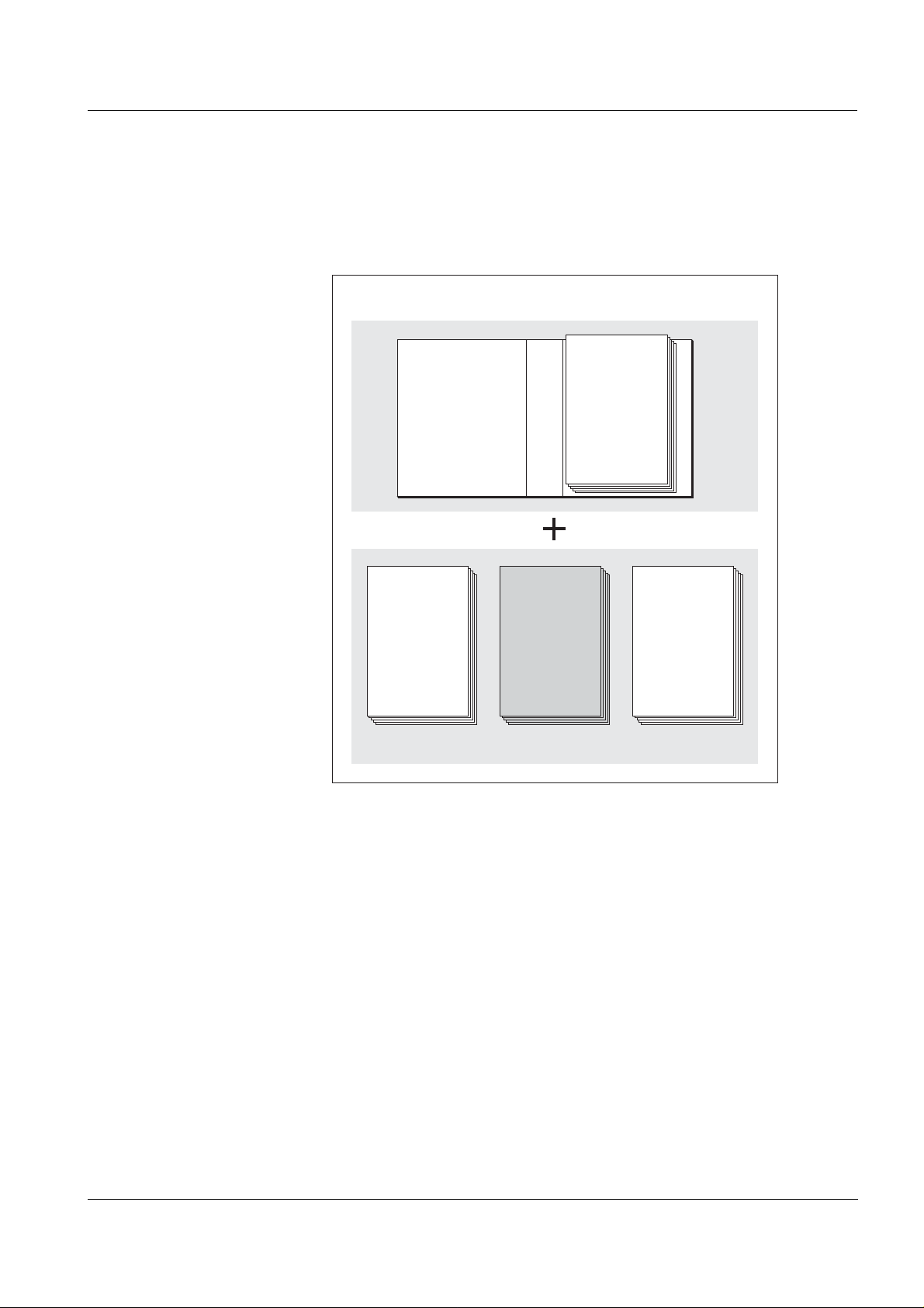
Fig. 1-1 Structure of the IQ SENSOR NET operating manual
The IQ SENSOR NET operating manual has a modular structure like the
IQ S
ENSOR NET system itsel f. It consists of a sy stem operating manual
and the operating manuals of all the components used.
Please file these component operating manual s into the ring binder of
the system operating manual.
1 - 1
Page 6

Overview MIQ/JB
1.2 Features of the MIQ/JB
General characteristics The MI Q/JB bran ching module is used for the distributed mounting of
the IQ S
tion.
The branching module can be used, for example, for:
ENSOR NET. It can be mounted at any position in a cable sec-
the branching of the IQ S
ENSOR NET, e.g. in order to integrate sev-
eral measurement locations spread out in the system
the multiple connection of sensors via the SACIQ sensor connectio n
cable, e.g. at the edge of the basin
setting up an operating site, i.e. the branching modu le provides a
possibility for the docking of terminal components.
The MIQ/JB simplifies the star-shaped configur ation of the
ENSOR NET for the optimum power supply of all components by
IQ S
power supply modules (see chapter I
IQ S
ENSOR NET system operating manual). If necessary, the number of
NSTALLATION of the
available connections at a single locat ion can be increased by stac ked
mounting of further MIQ modules.
With the standard MIQ module housing, the MIQ/JB has the same
characteristics as all MIQ modules regarding stability, leakproofness
and weather resistance. It also pr ovides the same wide variety of inst allation options (stacked mounting, canopy mounting, tophat rail mounting, etc.).
As many branching modules as required can be installed in a single
IQ S
ENSOR NET system.
1 - 2
Terminal strip The MIQ/JB has four equal SENSORNET connecti ons on the ter minal
strip inside the housing that can be used for all the purposes descri bed
above.
ba76030e01 01/2012
Page 7

MIQ/JB Safety instructions
2 Safety instructions
This component operating manual contains special instructions that
must be followed during the installation of the branching module. Thus,
it is essential to rea d this component operating manual b efore carrying
out any work with the system. In addition to this manual, the S
chapter of the IQ S
ENSOR NET system operating manual must be fol-
lowed.
Always keep this component operating manual together with the sys-
tem operating manual and all other component operating manuals in
the vicinity of the IQ S
ENSOR NET system.
Directions The following symbols indicate special features i n the indi vidual chap-
ters of this operating manual:
Note
indicates notes that draw your attention to special features.
AFETY
Note
indicates cross-references to other documents, e.g. operating manuals.
2.1 Authorized use
The authorized use of the MIQ/JB consists of its use as a branching
module in the IQ S
The technical specifications gi ven in chapter 5 T
observed. Only operation accor ding to the ins tructions in this operating
manual is authorized.
Any other use is considered to be unauthorized. Unauthorized use
invalidates any claims with regard to the guarantee.
ENSOR NET.
ECHNICAL DATA must be
ba76030d01 01/2012
2 - 1
Page 8

Safety instructions MIQ/JB
2.2 General safety instructions
The MIQ/JB is constructed and inspected in accordance with the relevant guidelines and norms for electronic instruments (see chapter 5
T
ECHNICAL DATA).
It left the factory in a safe and secure technical condition.
Function and operating
safety
Safe operation If safe operation is no longer possi ble, the MIQ/JB must be taken out of
The failure-free function and operational safety of the MIQ/JB is only
guaranteed if the generally applicabl e safety measures and the special
safety instructions in this oper ating manual ar e foll owed during i ts use.
The failure-free function and operational safety of the MIQ/JB is only
guaranteed under the environmental conditions that a re speci fied in
chapter 5 T
ECHNICAL DATA.
operation and secured against inadvertent operation.
Safe operation is no longer possible if the MIQ/JB:
has been damaged in transport
has been stored under adverse conditions for a lengthy period of
time
is visibly damaged
no longer operates as described in this manual.
If you are in any doubt, contact the supplier of your MIQ/JB.
2 - 2
ba76030d01 01/2012
Page 9

MIQ/JB Installation
X6X6 X5X5 X4X4
SENSORNET 2SENSORNET 4
RED
RED
SHIELD
SHIELD
GREEN
GREEN
X3X3 X2X2 X1X1
SENSORNET 1SENSORNET 3
RED
RED
SHIELD
SHIELD
GREEN
GREEN
ON
OFF
SN TERMINATOR
3 Installation
3.1 Scope of delivery
The scope of delivery of the MIQ/JB is listed i n the INSTALLATION chapter of the system operating manual.
3.2 Installation in the IQ SENSOR NET
The IQ SENSOR NET provides a number of options for integrating the
MIQ/JB mechanically and electrically in the system (stacke d mounting,
distributed mounting, etc.). The various types of installation are
described in detail in the I
manual.
Terminal strip
NSTALLATION chapter of the system operat ing
ba76030d01 01/2012
Fig. 3-1 Terminal strip of the MIQ/JB
All SENSORNET connections are identical and can be used as
required for extending/bran ching the cable section or for the connection
of sensors.
3 - 1
Page 10

Installation MIQ/JB
3 - 2
ba76030d01 01/2012
Page 11

MIQ/JB Maintenance and cleaning
4 Maintenance and cleaning
4.1 Maintenance
The MIQ/JB requires no special maintenance. The general maint enance of IQ S
IQ S
ENSOR NET system operating manual.
4.2 Cleaning
The cleaning of IQ SENSOR NET components is described in the
IQ S
ENSOR NET system operating manual.
ENSOR NET components is described in the
ba76030d01 01/2012
4 - 1
Page 12

Maintenance and cleaning MIQ/JB
4 - 2
ba76030d01 01/2012
Page 13

MIQ/JB Technical data
5 Technical data
Note
Electrical data
General technical data on MIQ modules are given in the T
DATA chapter of the IQ SENSOR NET system operating manual.
Nominal voltage Max. 24 VDC
via the IQ S
chapter T
IQ S
ENSOR NET system operating manual).
ENSOR NET (for details, see
ECHNICAL DATA of the
Power consumption Approx. 0.1 W
Protective class III
ECHNICAL
Instrument safety
Terminal connections
Number of MIQ/JB in a
ENSOR NETsystem
IQ S
Any
Applicable norms – EN 61010-1
– UL 3111-1
– CAN/CSA C22.2 No. 1010.1
IQ SENSOR NET connections
4
Additional connectable SENSORNET terminator (terminating resistor)
Terminal type Screw-type terminal strip, accessible by
raising the lid
Terminal ranges Soli d wires:
0.2 ... 4.0 mm
2
AWG 24 .. . 1 2
Flexible wires:
0.2 ... 2.5 mm
2
Cable feeds 4 cable glands M16 x 1.5 on the underside
of the module
ba76030d01 01/2012
5 - 1
Page 14

Technical data MIQ/JB
5 - 2
ba76030d01 01/2012
Page 15

MIQ/JB Contact Information
6 Contact Information
6.1 Ordering & Technical Support
Telephone
Fax
: (937) 767-1058
Email
Mail: YSI Incorporated
Internet
When placing an order please have the following information availabl e:
YSI account number (if available) Name and Phone Number
Model number or brief description Billing and shipping address
Quantity Purchase Order or Credit Card
: (800) 897-4151
(937) 767-7241
Monday through Friday, 8:00 AM to 5:00 PM ET
: environmental@ysi.com
1725 Brannum Lane
Yellow Springs, OH 45387
USA
: www.ysi.com
6.2 Service Information
YSI has authorized service centers throughout the United States and
Internationally. For the neares t ser vice center inf ormati on, please vi si t
www.ysi.com
directly at 800-897-4151.
When returning a product for service , i nclude the Product Retur n f orm
with cleaning certification. Th e form must be completely fil led out for an
YSI Service Center to accept the instrument for service. The Product
Return form may be downloaded at www.ysi.com
‘Support‘ tab.
and click ‘Support’ or contact YSI Technical Support
and clicking on the
ba76030e01 01/2012
6 - 1
Page 16

Contact Information MIQ/JB
6 - 2
ba76030e01 01/2012
Page 17

Page 18

1725 Brannum Lane
Yellow Springs, Ohio 45387 USA
+1 937-767-7241
800-765-4974 (US)
FAX (937) 767-1058
Email: environmental@ysi.com
Internet: www.ysi.com
 Loading...