

Page 1
IQ SENSOR NET
Power
!
O
K
MIQ/IC2
Operating Manual
ba76034e01 01/2012
IQ SENSOR NET Current input module
2 x 0/4 ... 20 mA
with power supply/isolator feed-in
Page 2

MIQ/IC2
Note
For the most recent version of the manual, please visit www.ysi.com
.
Contact YSI
1725 Brannum Lane
Yellow Springs, OH 45387 USA
Tel: +1 937-767-7241
800-765-4974
Email: environmental@ysi.com
Internet: www.ysi.com
Copyright © 2012 Xylem Inc.
2
ba76034e01 01/2012
Page 3

MIQ/IC2 List of contents
MIQ/IC2 - List of contents
1 Overview . . . . . . . . . . . . . . . . . . . . . . . . . . . . . . . . . . . . 1-1
1.1 How to use this component operating manual . . . . . . . . 1-1
1.2 Feature s of the MIQ/IC 2 . . . . . . . . . . . . . . . . . . . . . . . . .1-2
2 Safety instructions . . . . . . . . . . . . . . . . . . . . . . . . . . . . 2-1
2.1 Authorized use . . . . . . . . . . . . . . . . . . . . . . . . . . . . . . . . 2-2
2.2 General safety instructions . . . . . . . . . . . . . . . . . . . . . . .2-2
3 Installation . . . . . . . . . . . . . . . . . . . . . . . . . . . . . . . . . . 3-1
3.1 Scope o f de livery . . . . . . . . . . . . . . . . . . . . . . . . . . . . . . 3-1
3.2 Installation in the IQ S
3.3 Connecting external meters to the current inputs . . . . .3-1
3.4 Instal la tion examples . . . . . . . . . . . . . . . . . . . . . . . . . . . 3-4
ENSOR NET . . . . . . . . . . . . . . . . . 3-1
4 Settings . . . . . . . . . . . . . . . . . . . . . . . . . . . . . . . . . . . . . 4-1
5 What to do if ... . . . . . . . . . . . . . . . . . . . . . . . . . . . . . . . 5-1
6 Maintenance and cleaning . . . . . . . . . . . . . . . . . . . . . 6-1
6.1 Maintenance . . . . . . . . . . . . . . . . . . . . . . . . . . . . . . . . . .6 -1
6.2 Cleaning . . . . . . . . . . . . . . . . . . . . . . . . . . . . . . . . . . . . .6-1
7 Technical data . . . . . . . . . . . . . . . . . . . . . . . . . . . . . . . 7-1
8 Contact Information . . . . . . . . . . . . . . . . . . . . . . . . . . . 8-1
8.1 Ordering & Technical Support . . . . . . . . . . . . . . . . . . . . 8-1
8.2 Service In fo rmation . . . . . . . . . . . . . . . . . . . . . . . . . . . . 8-1
9 Lists . . . . . . . . . . . . . . . . . . . . . . . . . . . . . . . . . . . . . . . . 9-1
9.1 Explanation of the messages . . . . . . . . . . . . . . . . . . . . . 9-1
9.1.1 Error messages . . . . . . . . . . . . . . . . . . . . . . . . .9-1
9.1.2 Informative messages . . . . . . . . . . . . . . . . . . . .9-2
9.2 Status in fo . . . . . . . . . . . . . . . . . . . . . . . . . . . . . . . . . . .9-2
ba76034e01 01/2012
0 - 1
Page 4

List of contents MIQ/IC2
0 - 2
ba76034e01 01/2012
Page 5
MIQ/IC2 Overview
IQ Sensor Net Operating Manual
System
Operating
Manual
(Ring Binder)
IQ Sensor
Operating
Manual
MIQ Module
Operating
Manual
MIQ Terminal
Operating
Manual
Component Operating Manuals
1Overview
1.1 How to use this component operating manual
Structure of the
IQ S
ENSOR NET
operating manual
ba76034e01 01/2012
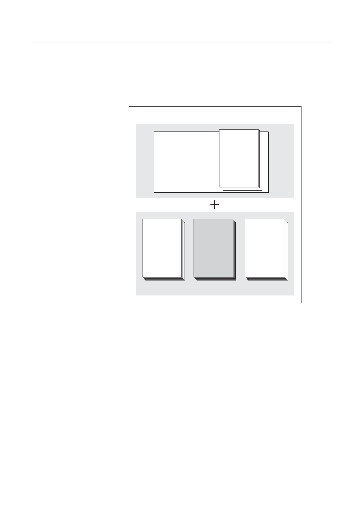
Fig. 1-1 Structure of the IQ SENSOR NET operating manual
The IQ SENSOR NET operating manual has a modular structure like the
IQ S
ENSOR NET itself. It consists of a system operating manual and the
operating manuals of all the components used.
Please file this component operat ing manual in to the ring binder of th e
system operating manual.
1 - 1
Page 6
Overview MIQ/IC2
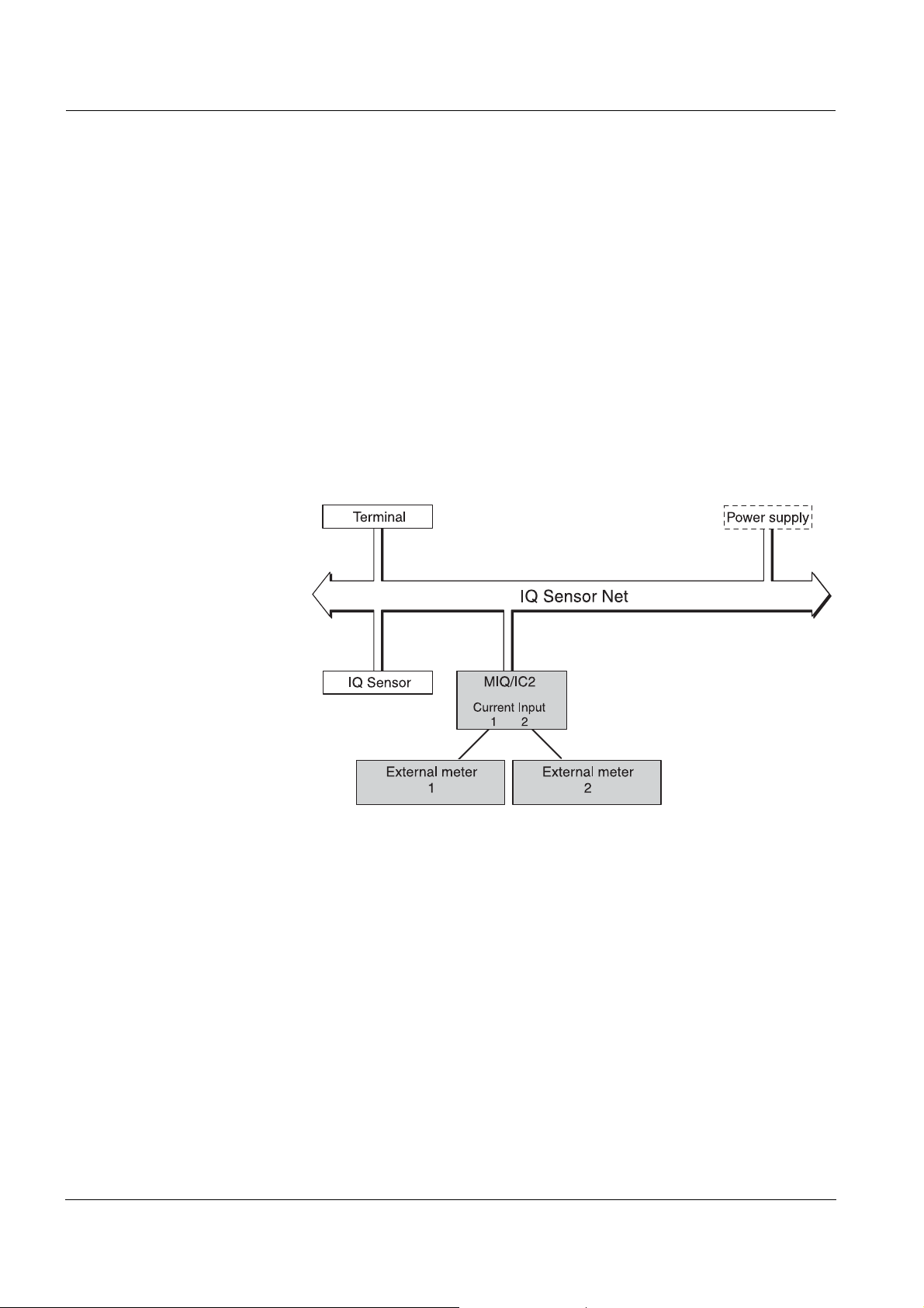
1.2 Features of the MIQ/IC2
General characteristics The MI Q/IC2 current input module provides two 0/4 ... 20 mA current
inputs for the IQ S
ters via their current output. Measured values of the external meters
can be displayed, recorded and processed like the measured values
from IQ S
ENSOR NET sensors.
Examples of external meters:
Measuring transmitters by YSI
Measuring transmitters by other manufactur ers
Measuring transmitters with explosion prot ection via a power sup-
ply/isolator
Analyzers
ENSOR NET and thus enables to connect external me-
1 - 2
Fig. 1-2 Connection of external meters to the IQ SENSOR NET
With the standard MIQ module housing, the MIQ/IC2 has the same
characteristics as all MIQ modules regarding stability, leakproofness
and weather resistance. It also pr ovides the same wide variety of inst allation options (stacked mounting, canopy mounting, tophat rail
mounting, etc.).
Terminal strip The MIQ/IC2 has the following electrical connections on the terminal
strip inside the housing:
2 x current input (0/4 ... 20 mA)
2 x SENSORNET connection
1 x power supply/isolator feed-in
ba76034e01 01/2012
Page 7
MIQ/IC2 Safety instructions
2 Safety instructions
This operating manual contains special instructions that must be
followed during the installation of the MIQ/IC2 cur rent input module.
Thus, it is essential for the operator to read this component operating
manual before carrying out any work with t he system. In addition to t his
manual, the S
manual must be followed.
Always keep this component operating manual together with the
system operating manual and all other component operating manuals
in the vicinity of the IQ S
AFETY chapter of the IQ SENSOR NET system operating
ENSOR NET system.
General safety
instructions
Other labels
Safety instructions in this operat ing manual are identified by the
warning symbol (triangle) in the left column. The signal word (e. g.
"Caution") indicates the level of danger:
Warning
indicates instructions that must be followed precisely in order to
prevent serious dangers to persons.
Caution
indicates instructions that must be followed precisely in order to
avoid slight injuries or damage to the instrument or the
environment.
Note
This symbol indicates instructions that describe special features.
Note
indicates cross-references to other documents, e.g. operating manuals.
ba76034e01 01/2012
2 - 1
Page 8

Safety instructions MIQ/IC2
2.1 Authorized use
The authorized use of the MIQ/IC2 consists of the provision of two
0/4 ... 20 mA current inputs for the IQ S
ENSOR NET.
Please keep to the technical specifications according to chapter 7
T
ECHNICAL DATA. Only operation according to the i nstructions in this
operating manual is authorized.
Any other use is considered to be unauthorized. Unauthorized use
invalidates any claims with regard to the guar antee.
2.2 General safety instructions
The MIQ/IC2 is constructed and inspected according to the relevant
guidelines and norms for electronic instruments (see chapter 7
T
ECHNICAL DATA).
It left the factory in a safe and secure technical condition.
Function and
operational safety
The failure-free function and operational safety of the MIQ/IC2 is only
guaranteed if the generally applicabl e safety measures and the special
safety instructions in this oper ating manual ar e foll owed during i ts use.
The failure-free function and operational safety of the MIQ/IC2 is only
guaranteed under the environmental conditions that a re speci fied in
chapter 7 T
ECHNICAL DATA.
Safe operation If safe operation is no longer possible, the MIQ/IC2 must be taken out
of operation and secured against inadvertent operation.
Safe operation is no longer possible if the MIQ/IC2:
has been damaged in transport
has been stored under adverse conditions for a lengthy period of
time
is visibly damaged
no longer operates as described in this manual.
If you are in any doubt, contact the supplier of your MIQ/IC2.
2 - 2
ba76034e01 01/2012
Page 9

MIQ/IC2 Installation
3 Installation
3.1 Scope of delivery
The scope of delivery of the MIQ/IC2 is listed in the INSTALLATION
chapter of the system operating manual.
3.2 Installation in the IQ SENSOR NET
The IQ SENSOR NET provides a number of options to integrate the MIQ/
IC2 mechanically and electrically in the system (stacked mounting,
distributed mounting, etc.). The various types of installation are
described in detail in the I
manual.
NSTALLATION chapter of the system operat ing
Software requirements
of the IQ S
ENSOR NET
Software requirements for the settings of Unit and Measured parame-
ter:
Controller from version 2.58
Terminal from version 2.55
When using older software versions, i t is not possi ble to enter t exts for
the settings of Unit and Measured parameter. The measured value
display displays the numerical value of the correl ated measured value
without designation.
Note
It is possible to update the so ftware if your componen ts have older software versions. Contact the YSI service depar tment.
3.3 Connecting external meters to the current inputs Warning
If external electrical cir cuits that are subject to the danger of physical contact are incorrectly connect ed to the current inputs, ther e
may be a danger of life threatening electric shock. Electrica l circuits are regarded to be subject to the danger of physical contact
when there are voltages higher than the Safety Extra Low Voltage
(SELV).
General installation
instructions
ba76034e01 01/2012
Observe the following instructions when att aching connect ing wir es to
the terminal strip:
Shorten all the wires used to the length required for the installation.
Fit all wire ends with wire end sleeves before connecting them to the
terminal stri p .
3 - 1
Page 10

Installation MIQ/IC2
1
3
2
SENSORNET 2
SENSORNET 1
ON
OFF
X6
RED
RED
SN TERMINATOR
SHIELD
GREEN
SHIELD
GREEN
X5
X4
X3
X2
X1
X8
X9
X7
X11
X12
X10
24V
0/4...20mA0/4...20mA
Current
Input 1
Supply
max
240 mA
Current
Input 2
+ REC 1-+ REC 2 -
+ Power -
Any wires that are not used a nd project int o the housing must be cut
off as closely as possible to the cable gland.
Materials required Wire end sleeves, suitabl e for the connecting wires, with suitable
crimping tool
Cable gland with sealing ring (scope of delivery of the MIQ/IC2)
Tools Cable stripping knife
Wire stripper
Phillips screw driver
Small screw driv e r
Connecting lines to the
terminal strip
1 Open the module.
2 Open the dummy screw fitting under the required input. Keep
the dummy screw fitting for possible later modifications.
3 - 2
Fig. 3-1 Terminal strip MIQ/IC2
3 Screw the cable gland (pos. 1 in Fi g. 3-1) with the sealing ring
(pos. 2) into the module housing.
ba76034e01 01/2012
Page 11

MIQ/IC2 Installation
4 Loosen the coupling ring (pos. 3 in Fig. 3-1).
5 Feed the line through the cable gland in the module housing.
6 Connect the wi res to t he termi nal stri p. Whil e doi ng so, pay at-
tention to the specifications on the label located under the terminal strip.
7 Tighten the coupling ring (pos. 3 in Fig. 3-1).
Note
No free wires must be allowed to project into the housing. Otherwise
there is the risk of malfunction. Always cut of f any wires that are not i n
use as closely as possible to the cable gland.
8 Close the module.
ba76034e01 01/2012
3 - 3
Page 12

Installation MIQ/IC2
3.4 Installation examples
The following installation examples demonstrate the basi c application
of the MIQ/IC2.
Note
For installation, please always observe the installation and operating
manuals of the external meters.
Connecting external
meters directly
The current outputs of external measur ing systems can be direct ly connected to the current inputs of the MIQ/IC2 module.
If the connection data of t he external meter is suitable, it i s also possible
to supply the external meter with power by the power supply/isolator
feed-in on the MIQ/IC2 module.
3 - 4
Fig. 3-2 Connection diagram for the conn ection of external measuring s ystems to the
MIQ/IC2 module
ba76034e01 01/2012
Page 13

MIQ/IC2 Installation
IQ Sensor Net
2 x Power supply/isolator
Potentially
explosive area,
zone 1 / zone 2
4 … 20 mA
4 … 20 mA 4 … 20 mA
4 … 20 mA
Feed-in
1
5
7
3
4 8
11
12
11
12
+
+
+
+
Meter 1
Meter 2
+
5
+
1
7
3
4 8
MIQ/IC2
- +
X7 X8
X9
X10
X11
X12
+
+
Connecting external
meters via a power sup-
ply/isolator
The current outputs of external meters c an be directly connected to the
current inputs of the MIQ/IC2 module vi a a power su pply/i solato r. Connecting via a power supply/isolator is necessary for measurements in
potentially explosive areas, for example.
If the connection data of the power supply/ isolators is su itable, it is possible to supply up to two power suppl y/isolators with power vi a the feedin connector on the MIQ/IC2 module.
ba76034e01 01/2012
Fig. 3-3 Connection diagram for the connection of external meters situated in
potentially explosive areas to the MIQ/IC2 module
Warning
In potentially explosive areas, inst ruments may be install ed, commissioned and operated by specialist electricians only, and according to the relevant regulations and the instructions in the
relevant operating manuals.
3 - 5
Page 14

Installation MIQ/IC2
3 - 6
ba76034e01 01/2012
Page 15

MIQ/IC2 Settings
Active measured
current value at
the 0/4 ... 20 mA
current input
Correlated
measured value
(display value)
with Measured
parameter and
Unit
4 Settings
Overview The MIQ/IC2 module provides two 0/4 ... 20 mA current inputs for the
IQ S
ENSOR NET. Each current input appears in the measured value
display, the Edit list of sensors over view and the Settings of sensors
and diff. sensors menu.
Each current input is treated like a sensor ("current sensor") by the
IQ S
ENSOR NET and has a separate setting menu.
On initial commissioning, only current input 1 is registered on the
IQ S
ENSOR NET. The measured value display indicat es the value of the
current at current input 1 in mA.
The correlated measured value (display val ue) is displayed without any
designation of Unit and Measured parameter and, in the delivery
condition, is identical with the current value (default setting).
After the display values at the measuring range limits have been set
and the Unit and Measured parameter have been specified, the correlated measured value corresponds to the measured value of the sensor, e.g. of a DO sensor:
ba76034e01 01/2012
Fig. 4-1 Example: correlated measured value of a DO sensor
Activate current input 2 in the Settings of sensors and diff. sensors
menu of current input 1. The setting menus of both current inputs are
identical except for the activation of current input 2.
If the physical input current range is exceeded, OFL is displayed
(measuring range exceeded or undercut).
Note
The general operating principles are given in the system operating
manual or in the component operating manual of the terminal components.
4 - 1
Page 16

Settings MIQ/IC2
Settings The following settings can be made for the sensor (default settings are
marked in bold):
Menu item Possible settings Explanations
Measuring mode REC Measurement of the current at the
0/4 ... 20 mA current inputs
Measuring range 0..20 mA
4..20 mA
Decimal places none
1 (.0)
2 (.00)
3 (.000)
Display value (0/4 mA) depending on the setting of
the Decimal places:
Display value (20 mA)
-9999 ... 20 ... 99999
-99.9 ... 20.0 ... 999.9
-9.99 ... 20.00 ... 99.99
0.000 ... 2.000 ... 9.999
Error detection >= Error threshold
<= Error threshold
Two measuring ranges can be selected.
The setting should agree with the output
range of the external sensor.
Display accuracy of the correlated measured value (display value).
The setting of the Decimal places affects
the maximum limits of the correlated measured value (see settings of displa y value).
Lower and upper limit of the measuring
range for the displayed, correlated measured value.
The maximum measuring range limits to
be set depend on the setting of the
Decimal places.
Specification whether an invalid measur ed
value ("----") is displ ayed if the current li mit
value (Error threshold) is exceeded or un-
dercut.
Error thresh o ld 0.5 ... 20.5 ... 21.5 mA Current limit value. If it is reached and ex-
ceeded or undercut, an error should be
displayed (see setting of Error detection).
Display indications for diff erent settings of
Measuring range, Error threshold and Error detection:
Fig. 4-2 Measuring range 0... 20 mA, Error detection >= Error threshold (IF),
= 20.5 mA
I
F
4 - 2
ba76034e01 01/2012
Page 17

MIQ/IC2 Settings
Fig. 4-3 Measuring range: 4 ... 20 mA, Error detection >= Error threshold (IF);
= 20.5 mA
I
F
Fig. 4-4 Measuring range: 4 ... 20 mA, Error detection <= Error threshold (IF)
= 3.5 mA
I
F
Menu item Possible settings Explanations
Unit ..... Entry of texts for Unit and Measured para-
meter. The texts entered appear in the
Measured parameter .....
measured value display next to the measured value.
The text is entered with
d and g
(see system operating manual)
e.g. Unit = mg/l
e.g. Measured parameter = O2
MIQ/IC2 REC2
(in the setting menu of
active
inactive
Activate or deactivate current input 2
current input 1 only)
Save and quit The system confirms the saving of the set-
tings and the display switches to the next
higher level.
Quit The display switches to the next higher
level without saving the new settings.
Carrying out settings
1 Switch to the measured value display with m.
ba76034e01 01/2012
2 Open the Settings menu with
s.
3 Select and conf irm the menu item Settings of sensors and diff.
sensors -> column Measuring range with
4 Select an entry with
d.
d and g.
4 - 3
Page 18

Settings MIQ/IC2
Fig. 4-5 140 - Settings of sensors and diff. sensors
5 Confirm the selection with g.
The settings of the sensor are displayed.
4 - 4
Fig. 4-6 140 - Settings of sensors and diff. sensors
6 Make the sensor settings with d and confirm each of them
with
g.
7 Select the Save and quit menu item with
d and confirm with
g. The new settings are stored in the sensor.
ba76034e01 01/2012
Page 19

MIQ/IC2 What to do if ...
5 What to do if ...
No measured value
Cause Remedy
– MIQ/IC2 not connected – Connect the MIQ/IC2
– Unknown – Look in the log book
Measurement provi des
implausible measured
values
Display of OFL
Cause Remedy
– Unsuitable settings of:
– Measuring range,
– Adjust the setting s in the setting
menu of the MIQ/IC2
– Display value (0/4 mA),
– Display value (20 mA)
– Current value at the current
input or output of an instru-
ment (e.g. measuring trans-
mitter, power supply/isolator,
– Change the settings of the
external m et e rs as necessary
– Adjust the setting s in the setting
menu of the MIQ/IC2
MIQ/IC2 etc.) does not agree
with the nominal value
– Calibration is not up-to-date – Calibrate the external meter
Cause Remedy
– Allowed signal range excee-
ded or undercut
– Operate the 0/4 ... 20 mA cur-
rent inputs of the MIQ/IC2 in the
allowed current range only (see
chapter 7 T
ECHNICAL DATA)
ba76034e01 01/2012
5 - 1
Page 20

What to do if ... MIQ/IC2
5 - 2
ba76034e01 01/2012
Page 21

MIQ/IC2 Maintenance and cleaning
6 Maintenance and cleaning
6.1 Maintenance
The MIQ/IC2 requires no special maintenance. The general maintenance of IQ S
IQ S
ENSOR NET system operating manual.
6.2 Cleaning
The cleaning of IQ SENSOR NET components is described in the
IQ S
ENSOR NET system operating manual.
ENSOR NET components is described in the
ba76034e01 01/2012
6 - 1
Page 22

Maintenance and cleaning MIQ/IC2
6 - 2
ba76034e01 01/2012
Page 23

MIQ/IC2 Technical data
7 Technical data
Note
Electrical data
General technical data on MIQ modules are given in the T
DATA chapter of the IQ SENSOR NET system operating manual.
Nominal voltage Max. 24 VDC via the IQ SENSOR NET (for
details, see the T
the IQ S
ENSOR NET system operating
ECHNICAL DATA chapter of
manual)
Power consumption 0.2 ... 4.6 W
0.2 W: without supplying any power supply/
isolator
≤ 2.4 W: with one power supply/isolator
≤ 4.6 W: with two power supply/isolators
ECHNICAL
Instrument safety
Terminal connections
Protective class III
Applicable norms – EN 61010-1
– UL 3111-1
– CAN/CSA C22.2 No. 1010.1
IQ SENSOR NET connections
2
Additional connectable SENSORNET terminator (terminating resistor)
Current inputs
2
(0/4 ... 20 mA)
Connector for power
1
supply/isolator
Terminal type Screw-type terminal strip, accessible by
opening the lid
Terminal ranges Solid wires: 0.2 ... 4.0 mm
2
AWG 24 ... 12
2
2
Line cross-section of cables carrying mains volt-
Flexible wires: 0.2 ... 2.5 mm
Europe: 1.5 ... 4.0 m m
USA: AWG 14 ... 12
age
ba76034e01 01/2012
Cable feeds 4 cable glands M16 x 1.5 on the underside
of the module
7 - 1
Page 24

Technical data MIQ/IC2
Current inputs
Measuring channels 2
Physically separated from the
IQ S
ENSOR NET
Physical input current
range
0.0 ... 22.5 mA
If this range is exceeded, the input switches
itself off for approx. one minute as a protective measure
Allowed signal ranges 0 ... 20 mA: 0.0 mA ≤ I ≤ 20.2 mA
4 ... 20 mA: 3.8 mA ≤ I ≤ 20.2 mA
Undefined signal ranges
Display of OFL
(range within the physi-
At the lower end of the signal range
(with signal range 4 ... 20mA only):
I
Error threshold
< I < 3.8 mA
cal input current range
but outside of the allowed signal range)
Error signal ranges
Display of "- ---"
At the upper end of the signal range
(with signal range 0/4 ... 20mA only):
20.2 mA < I < I
Error threshold
Error detection <= Error threshold:
0.0 mA ≤ I ≤ I
Error threshold
(corresponding to
setting of Error detec-
tion)
Error detection >= Error threshold:
I
Error threshold
≤ I ≤ 22.5 mA
Feed-in
(power supply/isolator)
Allowed common-mode
10 VDC, 20 VAC
difference between the
measuring channels
Measuring uncertainty
< 0.2 % of the measured value ± 0.01 mA
(precision)
Load max. 250 Ohm
Electrical data 20.5 - 24 V
Output current max. 240 mA,
permanently short-circuit proof
Requirement or monitor-
ing of the supply voltage
(only applies if a power
supply/isolator is connected)
21.5 ... 24 V
different from the IQ S
monitoring (see system operating manual)
The voltage monitoring values are automat-
ically changed when a power supply/is olator
is connected.
P-P
ENSOR NET voltage
7 - 2
ba76034e01 01/2012
Page 25

MIQ/IC2 Contact Information
8 Contact Information
8.1 Ordering & Technical Support
Telephone
Fax
: (937) 767-1058
Email
Mail: YSI Incorporated
Internet
When placing an order please have the following information availabl e:
YSI account number (if available) Name and Phone Number
Model number or brief description Billing and shipping address
Quantity Purchase Order or Credit Card
: (800) 897-4151
(937) 767-7241
Monday through Friday, 8:00 AM to 5:00 PM ET
: environmental@ysi.com
1725 Brannum Lane
Yellow Springs, OH 45387
USA
: www.ysi.com
8.2 Service Information
YSI has authorized service centers throughout the United States and
Internationally. For the neares t ser vice center inf ormati on, please vi si t
www.ysi.com
directly at 800-897-4151.
When returning a product for service , i nclude the Product Retur n f orm
with cleaning certification. Th e form must be completely fil led out for an
YSI Service Center to accept the instrument for service. The Product
Return form may be downloaded at www.ysi.com
‘Support‘ tab.
and click ‘Support’ or contact YSI Technical Support
and clicking on the
ba76034e01 01/2012
8 - 1
Page 26

Contact Information MIQ/IC2
8 - 2
ba76034e01 01/2012
Page 27

MIQ/IC2 Lists
9Lists
9.1 Explanation of the messages
In this chapter you will fi nd a lis t with all the mess age codes and cor responding message texts that may occur in the log book of the
IQ S
ENSOR NET system for the MIQ/IC2 current input module.
Note
Information about
Contents and structure of the log book and
Structure of the message code
can be found in the L
operating manual.
Note
All message codes of the MIQ/IC2 current input module end with the
number "381" (current input 1) or "382" (cur rent input 2).
9.1.1 Error messages
Message code Message text
EA9381
EA9382
Input current in undefined range
* Check settings and, if necessary, change them
* Check installation
* Check connected measuring system
* Check the MIQ/IC2
EAA381
EAA382
An error was reported
* Check settings and, if necessary, change them
* Check installation
* Check connected measuring system
* Check the MIQ/IC2
OG BOOK chapter of the IQ SENSOR NET system
EI1381 Operational voltage too low
* Check installation and cable lengths,
Follow installation instructions
* Power unit(s) overloaded, add power unit(s)
* Check terminal and module connections
* Defective components, replace components
EI2381 Operational voltage too low, no operation possible
* Check installation and cable lengths,
Follow installation instructions
* Power unit(s) overloaded, add power unit(s)
* Check terminal and module connections
* Defective components, replace components
ba76034e01 01/2012
9 - 1
Page 28

Lists MIQ/IC2
Message code Message text
ES1381 Component hardware defective
* Contact service
9.1.2 Informative messages
The MIQ/IC2 current input module does not send any info messages.
9.2 Status info
The status info is a coded piece of i nformat ion on the c urrent status of
a sensor. Each sensor sends this status info to the controller. The status info of sensors consists of 32 bits, each of whi ch can have the value
0 or 1.
General structure of the
status info
0 1 2 3 4 5 6 7 8 9 10 11 12 13 14 15
1 0 0 0 0 0 0 0 0 0 0 0 0 0 0 0 (general)
0 0 0 0 0 0 0 0 0 0 0 0 0 0 0 0 (internal)
16 17 1 8 1 9 2 0 2 1 22 2 3 24 25 26 27 28 29 30 31
The bits 0 - 15 are reserved for general information.
The bits 16 - 21 are reserved for internal service information.
The status info can be obtained as follows:
via a manual query in the menu, Einstellungen/Settings/Service/
Liste aller Teilnehmer (see system operating manual)
via an automatic query
– of a superior process control (e. g. when connected to the Profi-
bus)
– of the IQ Data Server (see IQ S
ENSOR NET Software Pack ope-
rating manual)
Note
The evaluation of the status inf o, e. g. in the c ase of an automati c query, has to be made individually for each bit.
9 - 2
MIQ/IC2
status info
Status bit Explanation
Bit 0 Component hardware defective
Bit 1-31 -
ba76034e01 01/2012
Page 29

Page 30

1725 Brannum Lane
Yellow Springs, Ohio 45387 USA
+1 937-767-7241
800-765-4974 (US)
FAX (937) 767-1058
Email: environmental@ysi.com
Internet: www.ysi.com
 Loading...