

Page 1
IQ SENSOR NET
MIQ/(A-)PR
Operating Manual
ba76020e01 01/2012
for the IQ S
PROFIBUS connection
ENSOR NET system 2020 XT USB
Page 2

MIQ/(A-)PR
Note
For the most recent version of the manual, please visit www.ysi.com
.
Contact YSI
1725 Brannum Lane
Yellow Springs, OH 45387 USA
Tel: +1 937-767-7241
800-765-4974
Email: environmental@ysi.com
Internet: www.ysi.com
Copyright © 2012 Xylem Inc.
2
ba76020e01 01/2012
Page 3

MIQ/(A-)PR Contents
PROFIBUS connection for the
IQ S
ENSOR NET system 2020 XT USB
1 Overview . . . . . . . . . . . . . . . . . . . . . . . . . . . . . . . . . . . . . . 5
1.1 How to use this component operating manual . . . . . . . . . 5
1.2 PROFIBUS and IQ S
ENSOR NET system 2020 XT USB . . 6
2 Safety instructions . . . . . . . . . . . . . . . . . . . . . . . . . . . . . . 7
2.1 Authorized use . . . . . . . . . . . . . . . . . . . . . . . . . . . . . . . . . 7
2.2 General safety instructions . . . . . . . . . . . . . . . . . . . . . . . . 8
3 Interface for the PROFIBUS . . . . . . . . . . . . . . . . . . . . . . 9
3.1 Scope of delivery . . . . . . . . . . . . . . . . . . . . . . . . . . . . . . . 9
3.2 The PROFIBUS module . . . . . . . . . . . . . . . . . . . . . . . . . 10
3.2.1 Terminal connections . . . . . . . . . . . . . . . . . . . . 11
3.2.2 Connecting the PROFIBUS cable . . . . . . . . . . . 12
3.2.3 Rotary address switches . . . . . . . . . . . . . . . . . . 16
3.2.4 PROFIBUS and module monitoring . . . . . . . . . 17
3.3 GSD file . . . . . . . . . . . . . . . . . . . . . . . . . . . . . . . . . . . . . 18
3.4 Commissioning . . . . . . . . . . . . . . . . . . . . . . . . . . . . . . . . 19
3.5 PROFIBUS checklist . . . . . . . . . . . . . . . . . . . . . . . . . . . 20
3.6 Sensor administration under PROFIBUS . . . . . . . . . . . . 21
3.6.1 Creating the assignment of sensor numbers . . 21
3.6.2 Creating the identical assignment of sensor
numbers in several systems . . . . . . . . . . . . . . . 22
3.6.3 Changing the assignment of sensor numbers . . 22
ba76020e01 01/2012
4 Data transmission . . . . . . . . . . . . . . . . . . . . . . . . . . . . . 23
4.1 Overview . . . . . . . . . . . . . . . . . . . . . . . . . . . . . . . . . . . . 23
4.2 Course of the data transmission . . . . . . . . . . . . . . . . . . 23
4.3 Output data . . . . . . . . . . . . . . . . . . . . . . . . . . . . . . . . . . 25
4.4 Input data . . . . . . . . . . . . . . . . . . . . . . . . . . . . . . . . . . . . 25
4.5 Data formats . . . . . . . . . . . . . . . . . . . . . . . . . . . . . . . . . . 26
5 What to do if ... . . . . . . . . . . . . . . . . . . . . . . . . . . . . . . . . 29
5.1 Fault diagnosis . . . . . . . . . . . . . . . . . . . . . . . . . . . . . . . . 29
5.2 Error elimination . . . . . . . . . . . . . . . . . . . . . . . . . . . . . . . 29
6 Technical data . . . . . . . . . . . . . . . . . . . . . . . . . . . . . . . . 31
6.1 IQ SENSOR NETComponentMIQ/(A-)PR . . . . . . . . . . . . . 31
6.2 PROFIBUS module . . . . . . . . . . . . . . . . . . . . . . . . . . . . 32
7 Contact Information . . . . . . . . . . . . . . . . . . . . . . . . . . . . 33
3
Page 4

Contents MIQ/(A-)PR
7.1 Ordering & Technical Support . . . . . . . . . . . . . . . . . . . . 33
7.2 Service Information . . . . . . . . . . . . . . . . . . . . . . . . . . . . . 33
4
ba76020e01 01/2012
Page 5

MIQ/(A-)PR Overview
IQ Sensor Net Operating Manual
System
Operating
Manual
(Ring Binder)
IQ Sensor
Operating
Manual
MIQ Module
Operating
Manual
MIQ Terminal
Operating
Manual
Component Operating Manuals
1Overview
1.1 How to use this component operating manual
The present operating manual complements the system operating
Structure of the
ENSOR NET
IQ S
operating manual
manual for the IQ S
description of the -PR option of the MIQ/(A-)PR module.
File this operating manual directly behind the system operating manual.
ENSOR NET system 2020 XT USB. It contains the
ba76020e01 01/2012
Fig. 1-1 Structure of the IQ SENSOR NET operating manual
The IQ SENSOR NET operating manual has a modular structure like the
ENSOR NET system itself. It consists of the system operating
IQ S
manual and the operating manuals of all the components used.
The space in the ring binder behind the system operating manual is
intended for filing the component operating manuals. Please file all
component operating manuals here so that all information is quickly
available in one location.
5
Page 6
Overview MIQ/(A-)PR
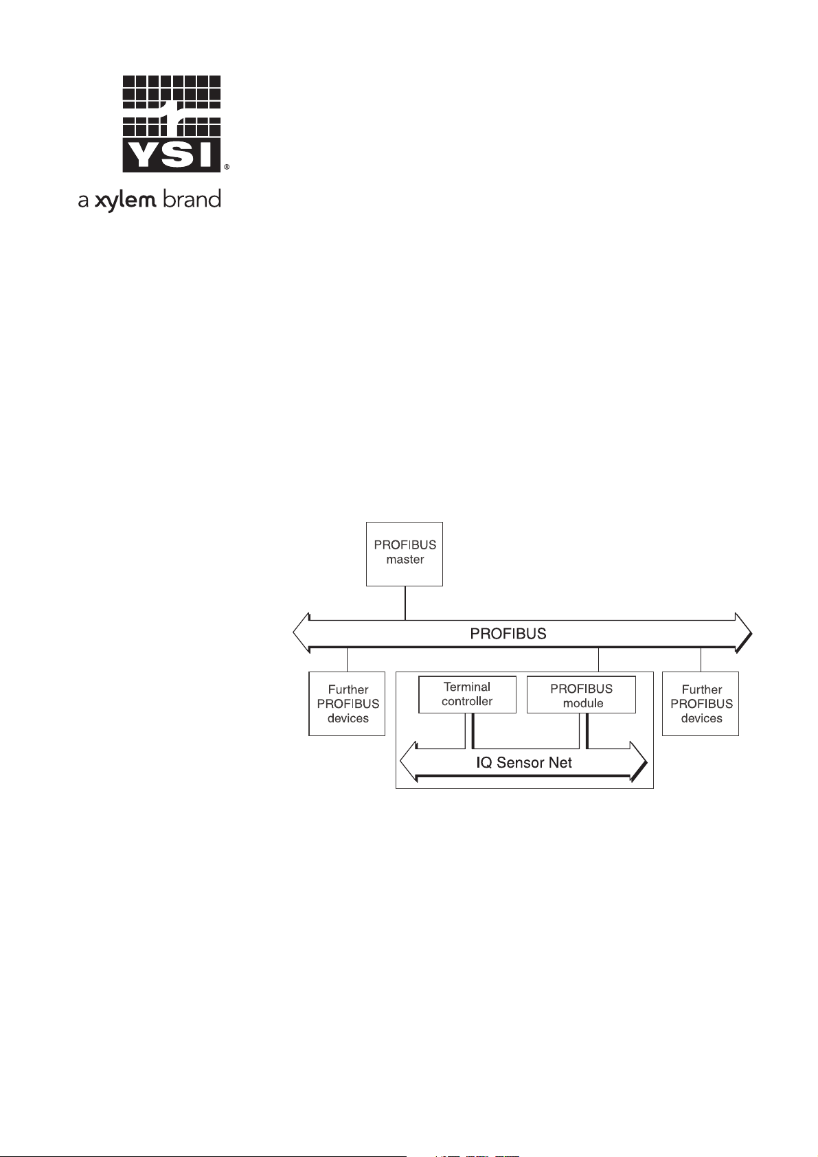
1.2 PROFIBUS and IQ SENSOR NET system 2020 XT USB
System communication The functional units of the IQ SENSOR NET are connected with one
another via a common line (Fig. 1-2). The line consists of two wires and
a shield. It transports digital information between the controller and the
other modules. At the same time, the line is used to supply all modules
with electrical voltage from a power supply unit. The power supply unit
is only required for the power supply and is not used in the system
communication.
With the -PR option, the MIQ/(A-)PR module upgrades the system
communication by an interface to the PROFIBUS master. Via this
interface the data exchange with the PROFIBUS master takes place.
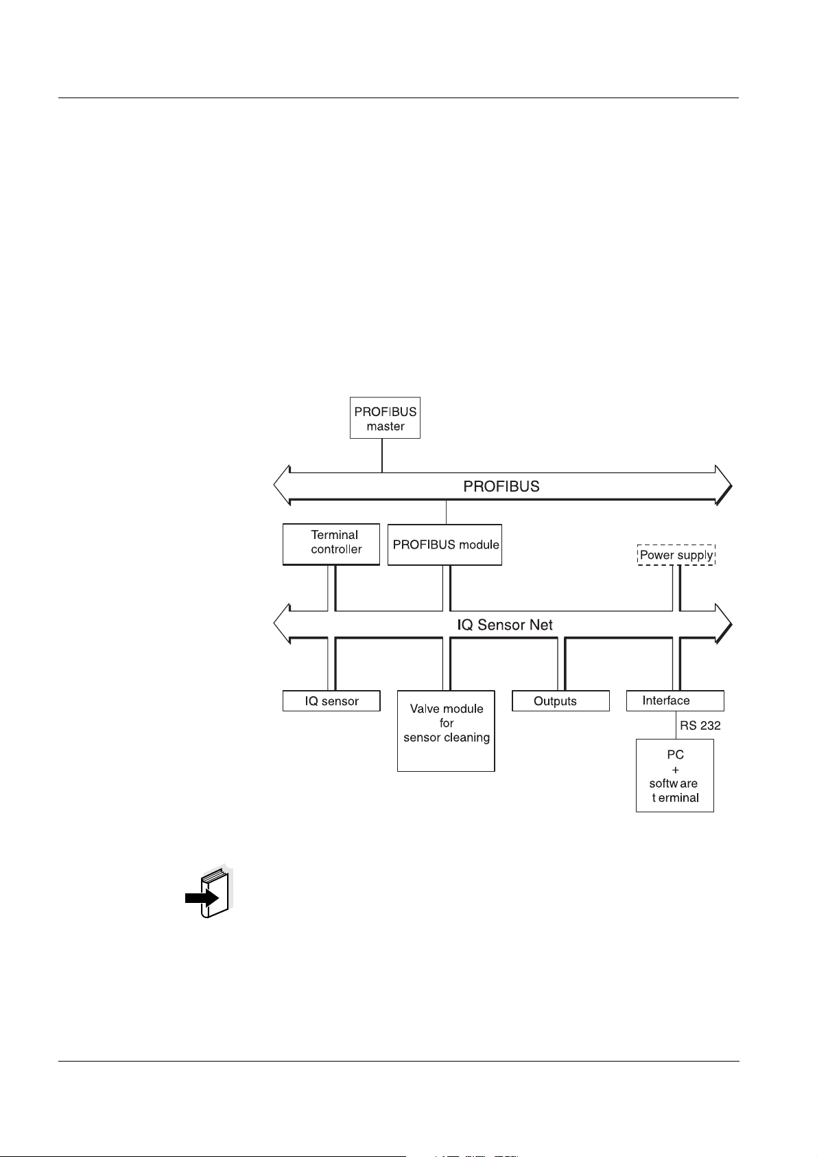
Fig. 1-2 Functional units of the IQ SENSOR NET with connection to the PROFIBUS
Note
All other general information on components, functions and operation
of the IQ S
ENSOR NET system 2020 XT USB is given in the system
operating manual.
With the A option, the MIQ/(A-)PR module extends the IQ S
ENSOR NET
system by a fully automatic air pressure compensation for D.O. sensors
(see system operating manual).
6
ba76020e01 01/2012
Page 7

MIQ/(A-)PR Safety instructions
2 Safety instructions
This component operating manual contains special instructions that
must be followed during the installation of the PROFIBUS module.
Thus, it is essential to read this component operating manual before
carrying out any work using this sensor. In addition to this manual, the
S
AFETY chapter of the IQ SENSOR NET system operating manual must
be followed.
Always keep this component operating manual together with the
system operating manual and all other component operating manuals
in the vicinity of the IQ S
Directions The following symbols indicate special features in the individual
chapters of this operating manual:
Note
indicates notes that draw your attention to special features.
ENSOR NET system.
Note
indicates cross-references to other documents, e.g. operating
manuals.
2.1 Authorized use
Authorized use of the MIQ/(A-)PR consists of its use as an interface to
a PROFIBUS.
Please observe the technical specifications according to chapter 6
T
ECHNICAL DATA. Only operation according to the instructions in this
operating manual is authorized.
Any other use is considered to be unauthorized. Unauthorized use
invalidates any claims with regard to the guarantee.
ba76020e01 01/2012
7
Page 8

Safety instructions MIQ/(A-)PR
2.2 General safety instructions
The MIQ/(A-)PR is constructed and inspected in accordance with the
relevant guidelines and norms for electronic instruments (see chapter
6T
ECHNICAL DATA).
It left the factory in a safe and secure technical condition.
Function and
operational safety
The failure-free function and operational safety of the MIQ/(A-)PR is
only guaranteed if the generally applicable safety measures and the
special safety instructions in this operating manual are followed during
its use.
The failure-free function and operational safety of the MIQ/(A-)PR is
only guaranteed under the environmental conditions that are specified
in chapter 6 TECHNICAL DATA.
Safe operation If safe operation is no longer possible, the MIQ/(A-)PR must be taken
out of operation and secured against inadvertent operation.
Safe operation is no longer possible if the MIQ/(A-)PR:
has been damaged in transport
has been stored under adverse conditions for a lengthy period of
time
is visibly damaged
no longer operates as described in this manual.
If you are in any doubt, contact the supplier of your MIQ/(A-)PR.
8
ba76020e01 01/2012
Page 9

MIQ/(A-)PR Interface for the PROFIBUS
3 Interface for the PROFIBUS
The MIQ/(A-)PR PROFIBUS module enables to connect the
ENSOR NET with all the sensors connected to it to the digital
IQ S
connection of a superordinate process control.
The AnyBus-S module for PROFIBUS DP of the HMS INDUSTRIAL
NETWORKS AB company is mounted in the MIQ/(A-)PR for this.
Note
Further instructions for the installation and operation of a PROFIBUS
network is given on the Internet under www.profibus.com and
www.hms-networks.com.
3.1 Scope of delivery
The scope of delivery of the MIQ/(A-)PR module comprises:
MIQ/PR or MIQ/A-PR
PROFIBUS module, AnyBus-S module for PROFIBUS-DP,
mounted in the MIQ/(A-)PR module
4 x screwed cable glands with seals and blind plugs
2 x ISO blind nuts (M4)
2 x cheese-head screws (M4x16) with plastic washer
1 x contact base
2 x plastic tapping screws for fixing the contact base
CD-ROM containing GSD file
Operating manual.
ba76020e01 01/2012
9
Page 10
Interface for the PROFIBUS MIQ/(A-)PR
AnyBus-S module
for Profibus-DP
2
3
4
5
ON
OFF
1
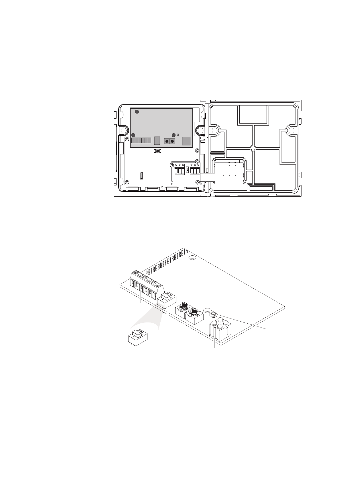
3.2 The PROFIBUS module
The PROFIBUS module (AnyBus-S module for PROFIBUS-DP) is
mounted in the MIQ/(A-)PR module.
PROFIBUS module
Fig. 3-1 AnyBus-S module for PROFIBUS-DP in the MIQ/(A-)PR
The AnyBus-S module for PROFIBUS DP provides an interface to
which a PROFIBUS master has read and write access. The
PROFIBUS module supplies the PROFIBUS master with data.
Fig. 3-2 Elements of the AnyBus-S module for PROFIBUS-DP
10
1 PROFIBUS DP terminal strip
2 PROFIBUS terminator switch
3 Rotary address switches
4 LEDs for PROFIBUS diagnosis
5 LED for module diagnosis
ba76020e01 01/2012
Page 11

MIQ/(A-)PR Interface for the PROFIBUS
1
6
2
3
4
5
3.2.1 Terminal connections
Fig. 3-3 Terminal connections
Pin Name Function
1 +5 V BUS Insulated +5 V from RS 485
2 GND BUS Insulated GND from RS 485
3 A line Negative RxD/TxD according to RS 485
specification
4 B line Positive RxD/TxD according to RS 485
specification
5 Shield BUS cable screen, connected with PE
6 RTS Request To Send
To check the wiring, the connection designations of a 9-pole D-SUB
plug connection are given here:
Pin Color* Name Function
1 -
2 -
3 Red B line Positive RxD/TxD
according to RS 485 specification
4 RTS Request To Send
5 GND BUS Reference potential for data wires and
terminating resistors
6 +5 V BUS Supply voltage for terminating resistors
7 -
8 Green A line Negative RxD/TxD
according to RS 485 specification
9 -
* Wire colors when using a standard PROFIBUS cable.
ba76020e01 01/2012
11
Page 12

Interface for the PROFIBUS MIQ/(A-)PR
(A)
(B)
(A)
Instruments connected
to the PROFIBUS,
e.g. MIQ/MC(-A)-PR
PROFIBUS cable
L1: approx. 15 mm
L2: approx. 5 mm
L2L1
Profibus wires
Shield
Insulating tape
3.2.2 Connecting the PROFIBUS cable
The MIQ/(A-)PR component can be connected at the PROFIBUS end
(A) or with a loop-through (B).
Fig. 3-4 Connection options of the MIQ/(A-)PR at the PROFIBUS cable,
(A) at the end or (B) with loop-through
(A)
Connecting the
MIQ/(A-)PR component
at the PROFIBUS end
1 Carefully strip the PROFIBUS cable insulation for approx. 20
mm.
2 Bare the PROFIBUS wires from the shielding braid and strip
them for approx. 5 mm.
3 Twist the shielding braid and cover it with approx. 15 mm
insulating tube.
4 Feed the PROFIBUS cable through the cable gland into the
module housing of the MIQ/(A-)PR.
5 Additionally insulate the transition between cable sheath and
insulating tube of the shielding braid (e.g. with insulating tape
or shrinkable tubing), so that no shielding braid is uncovered.
12
Fig. 3-5 PROFIBUS cable with insulating tape
6 Connect the PROFIBUS wires and shield to the terminal
connections of the PROFIBUS module (connections ALine,
BLine and Shield, see section 3.2.1).
ba76020e01 01/2012
Page 13

MIQ/(A-)PR Interface for the PROFIBUS
AnyBus-S module
for Profibus-DP
Fig. 3-6 Connection of the MIQ/(A-)PR as a PROFIBUS end device
7 Fasten the cap nut of the screwed cable gland.
8 Check and if necessary correct the position of the PROFIBUS
terminator switch.
The switch must be in the ON position.
9 Perform the check:
Check whether the wires and cables are screwed on tightly.
Insulate open wires.
Remove any cable remains from the MIQ/(A-)PR module.
10 Close the MIQ/(A-)PR module.
Note
Using a shielding terminal, connect the shield of the PROFIBUS cable
to the potential equalization or grounding system of the plant in the
vicinity but outside of the MIQ module housing.
ba76020e01 01/2012
13
Page 14

Interface for the PROFIBUS MIQ/(A-)PR
1
2
5
7
4
3
6
(B)
Connecting the
MIQ/(A-)PR component
at the
PROFIBUS with a loop-
through
To loop the PROFIBUS cable through the MIQ/(A-)PR component, a
shielding terminal is included in the scope of delivery.
Fig. 3-7 Shielding terminal with PROFIBUS cable and shield connection cable
1 Screw
2 Washer
3 Insulating part of the shielding terminal
4 Cable insulation of the PROFIBUS cable
5 Shielding braid of the PROFIBUS cable
6 Wires of the PROFIBUS cable
7 Shield connection wire
1 Carefully strip the cable insulation of both PROFIBUS cables
for approx. 35 mm.
2 Shorten the exposed shielding braid to approx. 15 mm.
3 Bare the PROFIBUS wires for approx. 5 mm.
4 Feed both cables through the free cable glands into the
module housing of the MIQ/(A-)PR.
5 Create a shield connection wire (7). To do so, strip a wire on
both ends for approx. 5 mm and 10 mm.
6 Insert a washer in the insulating part (3) of the shielding
terminal.
7 Feed both PROFIBUS cables into the insulating part (3) and
lead them through the insulating part.
8 Feed the long stripped end of the shield connection wire (7)
into the insulating part (3) of the shielding terminal.
14
ba76020e01 01/2012
Page 15

MIQ/(A-)PR Interface for the PROFIBUS
approx.
15 mm
approx.
15 mm
approx.
5 mm
4 2
6
7
1
3
AnyBus-S module
for Profibus-DP
9 Position the second washer and screw it tight.
Fig. 3-8 Shielding terminal with PROFIBUS cable (view from above)
10 Shorten the wires of the shielding braid if they protrude over
the shielding terminal.
11 Put the PROFIBUS wires together in pairs.
12 Connect the PROFIBUS wires and shield to the terminal
connections of the PROFIBUS module (connections ALine,
BLine and Shield, see section 3.2.1).
ba76020e01 01/2012
Fig. 3-9 Looping the PROFIBUS cable through an MIQ/(A-)PR
13 Fasten the cap nut of the screwed cable gland.
15
Page 16

Interface for the PROFIBUS MIQ/(A-)PR
14 Check and if necessary correct the position of the PROFIBUS
terminator switch.
The switch must be in the OFF position.
15 Perform the check:
Check whether the wires and cables are screwed on tightly.
Insulate open wires.
Remove any cable remains from the MIQ/(A-)PR module.
16 Close the MIQ/(A-)PR module.
Note
Using a shielding terminal, connect the shield of the PROFIBUS cable
to the potential equalization or grounding system of the plant in the
vicinity but outside of the MIQ module housing.
3.2.3 Rotary address switches
Fig. 3-10 Rotary address switches
A prerequisite for the configuration of the AnyBus-S module for
PROFIBUS DP is the setting of its address. The address is set using
two rotary switches. The left-hand switch is used to set the tens digit,
whereas the right switch is used to set the ones digit of the address.
This enables addresses of 1-99 to be set.
Example To set an address of 64:
Turn the left-hand switch to 6,
turn the right-hand switch to 4.
Note
The address cannot be changed during operation. A change of the
address becomes only effective after the address setting was changed
and the system was reset (see system operating manual).
16
ba76020e01 01/2012
Page 17

MIQ/(A-)PR Interface for the PROFIBUS
4
1
2
3
3.2.4 PROFIBUS and module monitoring
The PROFIBUS module has 4 LEDs for monitoring the bus and one
LED for monitoring the PROFIBUS module. These 5 LEDs are
important aids for the monitoring and diagnosis of faults.
Bus monitoring The LEDs have the following meaning:
Fig. 3-11 LEDs for bus monitoring
LED Color Meaning
1 - Not used
2 Green The module is online (recognized by the
PROFIBUS master), data exchange is possible.
Off - The module is not online
3 Red The module is offline, data exchange is not
possible.
Off - The module is not offline
4 Flashes
red
at a
freq. of:
1 Hz - error in the configuration:
During the initialization of the module, IN and/or
OUT data word length does not correspond to the
data word length in the configuration of the
PROFIBUS master (GSD file).
2 Hz - error in the user settings:
During the initialization of the module, the data
word length/content setting in the user settings
does not correspond to the data word length/
content setting in the configuration of the
PROFIBUS master (GSD file).
4 Hz - error during the initialization of the ASIC for
PROFIBUS communication.
Off - No error diagnostics available.
ba76020e01 01/2012
17
Page 18

Interface for the PROFIBUS MIQ/(A-)PR
Module monitoring A two-color LED (for position of the LED, see section 3.2) is used for
monitoring the PROFIBUS module.
Monitoring function Color Flashing
frequency
ASIC and FLASH ROM error Red 2 Hz
Module not initialized Green 2 Hz
Module initialized and in operation Green 1 Hz
RAM error Red 1 Hz
DPRAM error Red 4 Hz
3.3 GSD file
The GSD file contains all necessary information on the PROFIBUS
module and is required by the configuration program of the PROFIBUS
master.
The GSD file for the IQ S
ENSOR NET is found on the CD-ROM provided
(file name: IQMC06D1.GSD). The current GSD file is also provided on
the Internet under www.ysi.com
.
18
ba76020e01 01/2012
Page 19

MIQ/(A-)PR Interface for the PROFIBUS
3.4 Commissioning
To connect the IQ SENSOR NET to the PROFIBUS, preparations are
required on the PROFIBUS module, on the PROFIBUS master and, if
necessary, also on the IQ S
ENSOR NET.
Preparing the
PROFIBUS module
Configuring the
PROFIBUS master
Preparing the
IQ S
ENSOR NET
1 Open the MIQ/(A-)PR module (see system operating manual).
2 Set up the address on the PROFIBUS module using the two
rotary address switches (see section 3.2.3).
3 Connect the cable to the PROFIBUS on the terminals of the
PROFIBUS module (see section 3.2.1).
4 Set up the Profibus terminator switch on the Profibus module
according to the Profibus installation regulations.
5 For the configuration of the PROFIBUS master, use the GSD
file for MIQ/(A-)PR provided on the CD-ROM.
Preparations on the IQ SENSOR NET may be necessary if the system is
to transmit the data of the sensors to the PROFIBUS with a specific
assignment of the sensors to sensor numbers (S01 ... S20) (see
section 3.6).
Note
The sensor numbers are automatically assigned by the IQ S
ENSOR NET
in the order in which sensors are recognized by the system. The current
assignment of sensor numbers to the sensors can be seen in the List
of sensors (see System operating manual, chapter List of sensors).
ba76020e01 01/2012
19
Page 20

Interface for the PROFIBUS MIQ/(A-)PR
3.5 PROFIBUS checklist
The following checklist supports you when planning, projecting and
installing a PROFIBUS plant with the IQ S
operation, you should be able to answer all questions with "Yes".
Is the [bus system] (bus segment) installed without branch lines?
Was the correct PROFIBUS cable used (cord type A according to
EN 50170)?
Are the poles of the signal lines A line and B line correctly connected
at all bus connections?
Is it guaranteed that there is no short-circuit between A line, B line
and cable shielding?
Is the shielding installed free of interruptions?
Are the guidelines for shielding and grounding being observed, and
doesn't any unallowed potential equalization current flow
via the shielding?
ENSOR NET. For smooth
Is the maximum cable length (per bus segment) observed for the
corresponding baud rate?
Do all devices support the required baud rate?
With 12 Mbit/s transmission rate only: Are the bus plugs suitable for
this baud rate?
Are exactly two terminators switched on at the ends of the [bus
system] (bus segment)?
Are the terminators supplied with voltage so the following applies:
U
B line
- U
> + 500 mV?
A line
Do all devices have individual bus addresses?
After changing the bus address, have the devices been restarted
(switched off and on again)?
Do the addresses projected in the master correspond to the actual
addresses? Are all addresses less than or equal to the parameter
HSA and less than 126 (HSA = Highest Station Address)?
Is the currently valid GSD being used? If you are in doubt, download
it from the Internet.
Have admissible bus parameters been set only? If you are in doubt
set them to default values.
20
ba76020e01 01/2012
Page 21

MIQ/(A-)PR Interface for the PROFIBUS
Is it guaranteed that the PROFIBUS master has consistent access
to the 16 byte sensor data structure?
Note for Siemens PLC with programming language STEP7:
The following commands have to be used for consistent access:
– SFC15 (for writing)
– SFC14 (for reading)
After commissioning:
Do all devices signal error-free behavior?
3.6 Sensor administration under PROFIBUS
Preparation of the IQ SENSOR NET for communication with the
PROFIBUS may require, e.g. the following:
Creating an IQ S
ENSOR NET system with specific assignment of
sensor numbers to sensors (see section 3.6.1)
Creating several IQ S
ENSOR NET systems with the identical
assignment of sensor numbers to sensors (see section 3.6.2)
Changing the order of the sensors in an already installed system
(see section 3.6.3)
3.6.1 Creating the assignment of sensor numbers
You want to install an IQ S
ENSOR NET system and, at the same time, to
create a specific sequence of sensor number assignments to the
sensors.
1 Carry out a system start without any sensors (see System
operating manual, chapter Installation).
2 Connect the sensors to the system in the required order. For
each sensor, wait until the sensor is recognized by the system
(see System operating manual, chapter Installation).
ba76020e01 01/2012
21
Page 22

Interface for the PROFIBUS MIQ/(A-)PR
3.6.2 Creating the identical assignment of sensor numbers in several systems
You want to install several identical IQ S
ENSOR NET systems and, at
the same time, create the same sequence of sensor number
assignments to the sensors in all systems.
1 Carry out a system start without any sensors (see System
operating manual, chapter Installation).
2 Connect the sensors to the system in the required order. For
each sensor, wait until the sensor is recognized by the system
(see System operating manual, chapter Installation).
3 Repeat steps 1 and 2 for all other systems and, while doing so,
keep to exactly the same order when connecting the sensors.
3.6.3 Changing the assignment of sensor numbers
You want to change the assignment of sensor numbers to the sensors
in an already running IQ S
ENSOR NET system.
1 Unplug all sensors from the IQ SENSOR NET.
2 Delete all inactive datasets in the list of sensors (see System
operating manual, chapter Deleting inactive datasets of
sensors).
3 Connect the sensors to the system in the required order. For
each sensor, wait until the sensor is recognized by the system
(see System operating manual, chapter Installation).
Note
When the inactive datasets are deleted, all settings for the sensors are
deleted as well.
22
ba76020e01 01/2012
Page 23

MIQ/(A-)PR Data transmission
4 Data transmission
4.1 Overview
Transmitted sensor data The following data for a sensor is transmitted to the PROFIBUS master
as a consistent data block:
Sensor number (Sxx)
Sensor status
Sensor model
Status info of sensors
Measuring mode
Measured value status (main and secondary measured value)
Main measured value
Secondary measured value
Note
The transmitted data of all IQ S
document, "IQ S
ENSOR NET sensors: encoded data for field bus
ENSOR NET sensors is given in the YSI
communication" (ba76073e). It is permanently updated when new
sensors are available and when the sensor software is modified (if the
modifications are relevant for the transmitted sensor data). The latest
version is available on the Internet, in the download area for operating
manuals. Use the search function for the download and search for
"ba76073e".
4.2 Course of the data transmission
The basis for data transmission between the PROFIBUS master and
IQ S
ENSOR NET is formed by the unique assignment of a sensor to its
sensor number (Sxx) in the IQ S
numbers are assigned by the system in the order in which the sensors
are recognized by the system.
The sensor number (Sxx) is the identification for a sensor. The sensor
number is always transmitted in the first byte of the output and input
data. Thus the PROFIBUS master can clearly query data of individual
sensors.
ENSOR NET system. The sensor
ba76020e01 01/2012
23
Page 24

Data transmission MIQ/(A-)PR
Read input data
Is sensor number identical
in input data and output data?
Is sensor number identical
in input data and output data?
Input data:
Process data for sensor
Input data:
Process data for sensor
Prompt data of a sensor
with a different sensor number?
Prompt data of a sensor
with a different sensor number?
Output data:
Allocate sensor number (Sxx) for a sensor
Output data:
Allocate sensor number (Sxx) for a sensor
no
no
Start
The data is transmitted in two steps:
The Profibus master transmits the request to the Profibus module to
supply data for the sensor with a certain sensor number.
The Profibus module checks whether the requested sensor number
is present and returns the data for the sensor with the respective
sensor number to the Profibus master.
24
Fig. 4-1 Course of the data transmission in the PROFIBUS master
ba76020e01 01/2012
Page 25

MIQ/(A-)PR Data transmission
4.3 Output data
(1 byte - from the PROFIBUS master to the IQ SENSOR NET)
Address Information Bit
Offset 0h Sensor number (Sxx) in the IQ S
ENSOR NET (Int8) Bit 7-0
4.4 Input data
(16 bytes - from the IQ SENSOR NET to the PROFIBUS master)
Address Information Bit
Offset 0h Sensor number (Sxx) (Int 8) Bit 7-0
Offset 1h Sensor status (Int8) Bit 7-0
Offset 2h Sensor model (Int16) Bits 15-8
Offset 3h Bit 7-0
Offset 4h Status info (Int16) Bits 15-8
Offset 5h Bit 7-0
Offset 6h Measuring mode (Int8) Bit 7-0
Offset 7h Measured value status (Int8)
Main measured value bits 7-4
Secondary measured value bits 3-0
Bit 7-0
Offset 8h Main measured value (IEEE-754 floating point, 32-
Offset 9h Bits 23-16
Offset Ah Bits 15-8
Offset Bh Bit 7-0
Offset Ch Secondary measured value (IEEE-754 floating point,
Offset Dh Bits 23-16
Offset Eh Bits 15-8
Offset Fh Bit 7-0
ba76020e01 01/2012
Bits 31-24
bit)
Bits 31-24
32-bit)
25
Page 26

Data transmission MIQ/(A-)PR
MSB* LSB*
SEEEEEEE
EMMMMMMM
M M M M M M M M
M M M M M M M M
)2...2221(21
23
0
3
20
2
21
1
22
127 −−−−−
⋅++⋅+⋅+⋅+⋅⋅−=
bbbb
ES
MMMMV
)2...222(21
23
0
3
20
2
21
1
22
126 −−−−−
⋅++⋅+⋅+⋅⋅⋅−=
bbbb
S
MMMMV
MSB LSB
4.5 Data formats
Measured values The data for the main and secondary measured values are transmitted
in the IEE-754 standard 32-bit floating point format.
Address Bit representation
Offset 0h bits 31-24 S = sign (bit 31)
Offset 1h bits 23-16
Offset 2h bits 15-8
Offset 3h bits 7-0
MSB = Most significant bit, LSB = Least significant bit
If not all of the bits of the exponent are 0, the value is calculated
according to:
E = exponent
(bits 30-23)
M = mantissa
(bits 22-0)
Sensor model
Status info
If all of the bits of the exponent are 0, the value is calculated according
to:
A value is 0 if all the bits of both the exponent as well as the mantissa
are 0.
Note
If the measured value is equal to 0, check the measured value status.
If the measured value status is not equal to 1, an error has occurred
and the measured value is invalid.
The data for the sensor model and status info is transmitted as INT16,
i.e. consists of 2 bytes. The assignment is carried out in Motorola
format (the higher value byte first).
Address Bit representation Information
Offset 0h bits 15-8 High byte
Offset 1h bits 7-0 Low byte
26
ba76020e01 01/2012
Page 27

MIQ/(A-)PR Data transmission
Measured value status The data for measured value status of the main and secondary
measured values are encoded jointly into a single byte. Bits 7-4 encode
the status of the main measured value, bits 3-0 encode the status of the
secondary measured value.
Other data All other data always consist of only a single byte (Int8).
ba76020e01 01/2012
27
Page 28

Data transmission MIQ/(A-)PR
28
ba76020e01 01/2012
Page 29

MIQ/(A-)PR What to do if ...
5 What to do if ...
5.1 Fault diagnosis
A simple diagnosis of the operability of the PROFIBUS module and
communication with the PROFIBUS is possible via the LEDs on the
PROFIBUS module in the MIQ/(A-)PR (see section 3.2.4).
5.2 Error elimination
Data transmission
between the Profibus
master and
IQ S
ENSOR NET system is
The PLC does not
receive any plausible
input data
faulty
Cause Remedy
– Incorrect wiring of the
connections on the terminal
strip
– Check/change the connections
(see section 3.2.1)
– Use checklist according to
section 3.5
– Incorrect setting of the
address
– Check/change the setting of
the address (see section 3.2.3)
– Incorrect protocol – Check the version of the GSD
file
– Adapt the protocol
– PROFIBUS module defective – Return the MIQ/(A-)PR to YSI
Cause Remedy
– Input data and output data
are not consistent
– When programming the PLC,
define input data and output
data as consistent over the
entire data length
ba76020e01 01/2012
– The data interpretation of the
PLC is not correct
– Observe the data alignment of
the PLC data representation. If
necessary, exchange the highorder and low-order bytes word
by word
29
Page 30

What to do if ... MIQ/(A-)PR
30
ba76020e01 01/2012
Page 31

MIQ/(A-)PR Technical data
6 Technical data
6.1 IQ SENSOR NETComponentMIQ/(A-)PR
General technical data for the IQ SENSOR NET are given in the system
Electrical data
operating manual for the IQ S
Nominal voltage Max. 24 VDC via the IQ S
Power consumption 3 W
Protective class III
ENSOR NET system.
ENSOR NET (for
details, see chapter T
ENSOR NET system operating manual).
IQ S
ECHNICAL DATA of the
Instrument safety
Terminal connections
Number of MIQ/(A-)PR
1
modules in an
ENSOR NET system
IQ S
Applicable norms – EN 61010-1
– UL 3111-1
– CAN/CSA C22.2 No. 1010.1
IQ SENSOR NET
connections
2
2 additional SENSORNET terminators that
can be activated (terminating resistors)
Terminal type Screw-type terminal strip, accessible by
opening the lid
Terminal ranges Solid wires:
0.2 ... 4.0 mm
2
AWG 24 ... 12
Flexible wires:
0.2 ... 2.5 mm
2
ba76020e01 01/2012
Cable feeds 4 cable glands M16 x 1.5 on the underside
of the module
31
Page 32

Technical data MIQ/(A-)PR
6.2 PROFIBUS module
Information on the technical data of the module AnyBus-S module for
Profibus DP of the HMS INDUSTRIAL NETWORKS AB company is
given in the documentation of the HMS INDUSTRIAL NETWORKS AB
company.
Note
Further information on the technical data of the Profibus module is
given on the Internet under the address of the manufacturer
HMS INDUSTRIAL NETWORKS AB
(www.hms-networks.com)
in the following documents:
FIELDBUS APPENDIX
ANYBUS-S PROFIBUS DP
AnyBus Slave Design Guide
ANYBUS-S Parallel Interface
32
ba76020e01 01/2012
Page 33

MIQ/(A-)PR Contact Information
7 Contact Information
7.1 Ordering & Technical Support
Telephone
Fax
: (937) 767-1058
Email
Mail: YSI Incorporated
Internet
When placing an order please have the following information available:
YSI account number (if available) Name and Phone Number
Model number or brief description Billing and shipping address
Quantity Purchase Order or Credit Card
: (800) 897-4151
(937) 767-7241
Monday through Friday, 8:00 AM to 5:00 PM ET
: environmental@ysi.com
1725 Brannum Lane
Yellow Springs, OH 45387
USA
: www.ysi.com
7.2 Service Information
YSI has authorized service centers throughout the United States and
Internationally. For the nearest service center information, please visit
www.ysi.com
directly at 800-897-4151.
When returning a product for service, include the Product Return form
with cleaning certification. The form must be completely filled out for an
YSI Service Center to accept the instrument for service. The Product
Return form may be downloaded at www.ysi.com
‘Support‘ tab.
and click ‘Support’ or contact YSI Technical Support
and clicking on the
ba76020e01 01/2012
33
Page 34

Contact Information MIQ/(A-)PR
34
ba76020e01 01/2012
Page 35

Page 36

1725 Brannum Lane
Yellow Springs, Ohio 45387 USA
+1 937-767-7241
800-765-4974 (US)
FAX (937) 767-1058
Email: environmental@ysi.com
Internet: www.ysi.com
 Loading...