

Page 1
Operations Manual
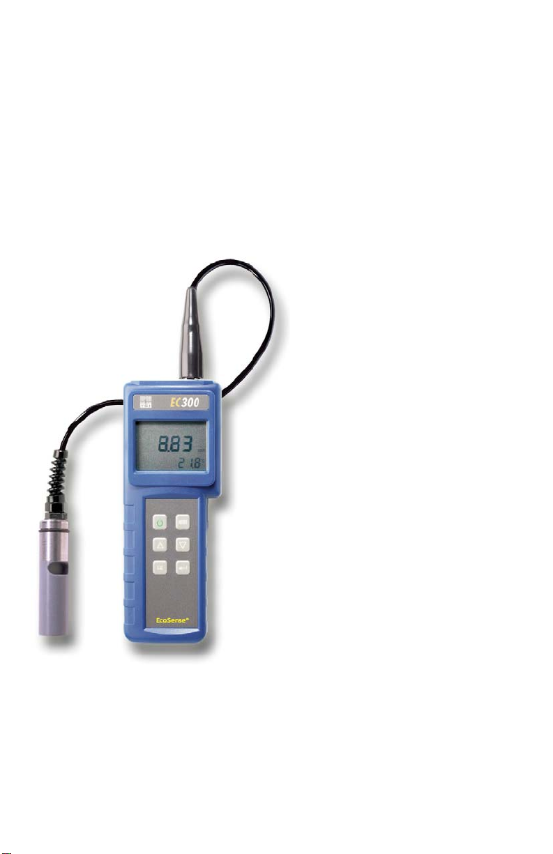
EcoSense® EC300
Conductivity, Salinity
and Temperature
Portable
Instrument
• English
• Français
• Español
• Deutsch
• Italiano
Page 2

WARRANTY
The EcoSense® EC300 Instrument is warranted for one year from date of purchase by the end user
against defects in materials and workmanship. EC300 probes and cables are warranted for one year
from date of purchase by the end user against defects in material and workmanship. Within the
warranty period, YSI will repair or replace, at its sole discretion, free of charge, any product that YSI
determines to be covered by this warranty.
To exercise this warranty, write or call your local YSI representative, or contact YSI Customer Service
in Yellow Springs, Ohio. Send the product and proof of purchase, transportation prepaid, to the
Authorized Service Center selected by YSI. Repair or replacement will be made and the product
returned, transportation prepaid. Repaired or replaced products are warranted for the balance of the
original warranty period, or at least 90 days from date of repair or replacement.
Limitation of Warranty
This Warranty does not apply to any YSI product damage or failure caused by: (i) failure to install,
operate or use the product in accordance with YSI’s written instructions; (ii) abuse or misuse of the
product; (iii) failure to maintain the product in accordance with YSI’s written instructions or standard
industry procedure; (iv) any improper repairs to the product; (v) use by you of defective or improper
components or parts in servicing or repairing the product; or (vi) modification of the product in any way
not expressly authorized by YSI.
THIS WARRANTY IS IN LIEU OF ALL OTHER WARRANTIES, EXPRESSED OR IMPLIED,
INCLUDING ANY WARRANTY OF MERCHANTABILITY OR FITNESS FOR A PARTICULAR
PURPOSE. YSI’s LIABILITY UNDER THIS WARRANTY IS LIMITED TO REPAIR OR
REPLACEMENT OF THE PRODUCT, AND THIS SHALL BE YOUR SOLE AND EXCLUSIVE
REMEDY FOR ANY DEFECTIVE PRODUCT COVERED BY THIS WARRANTY. IN NO EVENT
SHALL YSI BE LIABLE FOR ANY SPECIAL, INDIRECT, INCIDENTAL OR CONSEQUENTIAL
DAMAGES RESULTING FROM ANY DEFECTIVE PRODUCT COVERED BY THIS
WARRANTY.
CONTACT INFORMATION
YSI Inc. • 1725 Brannum Lane • Yellow Springs OH, 45387
800-897-4151 • 937-767-7241 • Fax: 937-767-1058
Email: ecosense@ysi.com
• Website: www.ysiecosense.com
1
Page 3

CONTENTS
WARRANTY.................................................................................................... 1
CONTACT INFORMATION............................................................................. 1
GENERAL INTRODUCTION .......................................................................... 3
INITIAL INSPECTION.....................................................................................3
SPLASH RESISTANCE.................................................................................. 3
BATTERY INSTALLATION............................................................................. 3
KEY FUNCTIONS OF THE MODEL EC300................................................... 4
THE LCD DISPLAY......................................................................................... 4
MEASUREMENT MODES.............................................................................. 4
CALIBRATION ................................................................................................ 5
TDS............................................................................................................ 5
CELL .......................................................................................................... 5
Temperature Coefficient ............................................................................ 5
Temperature Reference............................................................................. 5
Conductivity Calibration............................................................................. 5
CONDUCTIVITY MEASUREMENTS.............................................................. 5
PROBE MAINTENANCE ................................................................................ 6
TROUBLESHOOTING.................................................................................... 6
SPECIFICATIONS .......................................................................................... 7
RECOMMENDED SPARE PARTS LIST ........................................................ 7
2
Page 4

GENERAL INTRODUCTION
The EC300 is one of three instruments in the EcoSense product line from YSI. The EC300 is a
precision tool that measures conductivity, salinity and temperature. A built-in microprocessor
calculates and compensates for all parameters related to conductivity and temperature
determinations.
This unit has a splash-resistant IP65 case. The mechanical touch keys are highly reliable with
tactile and audio feedback. This instrument uses one 9V battery. Re-calibration is not required
when power is restored.
The front of the instrument has a large LCD that displays temperature and either temperature
compensated or non-temperature compensated conductivity, salinity or TDS simultaneously
along with user prompts and mode indicators. The unit prompts users through calibration and
measurement procedures.
The model EC300 is available with a single four-electrode cell. Other features include automatic
conductivity ranging, automatic temperature compensation, long battery life, and 50/60 Hz AC
noise rejection. This meter is universal and user-friendly for field, industrial and laboratory
applications.
INITIAL INSPECTION
Carefully unpack the unit and accessories, and inspect for shipping damages. Compare
received parts with materials listed on the packing list. Notify YSI immediately of any damage or
missing parts. Save all packing materials until satisfactory operation is confirmed.
SPLASH RESISTANCE
Though the EC300 instrument is housed in a splash proof case, DO NOT use it underwater; the
connector is not waterproof. The splash-resistant case prevents permanent damage to the unit if
accidentally dropped into non-corrosive solutions. In case of submersion, follow these steps
immediately:
1. Dry the connector if necessary, and replace the conductivity probe. Rinse unit carefully with
distilled water. After rinsing and drying, inspect and clean connectors to remove all
contaminants that may affect probe connections.
2. Wait for the unit and probe to dry completely before resuming operation.
3. If the unit does not function correctly after steps 1 and 2, call YSI for possible repair or
replacement (see Warranty).
BATTERY INSTALLATION
An initial display of “BAT” on the LCD indicates approximately one hour of
battery life for unit operation within specifications. Replace battery when
“BAT” appears on the LCD. (See Figure 1.)
To replace battery, remove the two battery cover screws, battery cover
and o-ring. Replace the 9V battery. Replace battery cover and o-ring
(align the o-ring properly to insure a good seal) and fasten the two battery
cover screws for the splash-resistant feature.
3
Figure 1.
Battery Installation
Page 5

KEY FUNCTIONS OF THE MODEL EC300
1. : Turns the unit ON or OFF. Calibration values are not erased when the unit is turned off.
When the unit is not in use, turn it off to save battery life. For long-term storage, remove the
battery.
2. MODE: Selects display mode. In Normal operation, press MODE to sequentially display
uncompensated conductivity, temperature compensated conductivity, salinity and total
dissolved solids (TDS). In calibration mode, this key exits the current calibration and
displays the next calibration parameter.
3. CAL: In normal operation, changes the mode from Normal to Calibration.
4.
(Enter) : In Calibration Set-up, press this key to save the current parameter to memory.
5. Δ and ∇ Keys: Increases or decreases the display value as desired.
THE LCD DISPLAY
1. CONDUCTIVITY: Displays when
measuring conductivity.
2. BAT: Low battery indicator.
3. Main display for compensated and
uncompensated conductivity, salinity
and TDS values.
4. CAL: Calibration mode indicator.
5. TDS: Displays when measuring total
dissolved solids.
6. SALINITY: Displays when measuring
salinity.
7. CELL: Indicates conductivity cell constant value.
8. °C: Flashes during temperature compensated conductivity measurement. During
calibration, indicates temperature reference unit.
%: Displays during calibration; indicates temperature coefficient unit.
9. ppt: Parts per thousand; indicates salinity measurement.
10. uS, mS: micro Siemens, milli Siemens; Indicates conductivity measurement.
11. g/L: grams/Liter; indicates TDS measurement.
12. °C: Temperature display.
2
3
4
Figure 1. LCD Display
51
6
7
8
9
10
11
12
MEASUREMENT MODES
1. Temperature - Current solution temperature continually displays.
2. Temperature Compensated Conductivity - Measurement of conductivity, compensated to
25°C or another specified value between 15 and 25°C. Expressed as uS/cm or mS/cm with
a flashing “°C”.
3. Uncompensated Conductivity – Direct measurement of conductivity, not compensated to
a specific temperature. Expressed as uS/cm or mS/cm.
4. Salinity – Measurement of salinity; expressed in parts per thousand (ppt).
5. TDS – Measurement of total dissolved solids (TDS); expressed in grams per liter (g/L)
Carefully observe the units displayed at the far side of the LCD to determine the desired mode.
4
Page 6

CALIBRATION
Calibration setup contains five sections: TDS, Cell, Temperature Coefficient, Temperature
reference, and Conductivity Calibration. To access these sections:
1. Connect the conductivity probe and cable assembly to the unit and turn the unit on. The
screen will display CELL and the cell constant of the conductivity probe.
2. Allow temperature readings to stabilize, then press CAL to enter the calibration mode; CAL
appears on the LCD. Press MODE to sequentially display the following sections:
Note: Press Enter (
advance to the next section. If there are no changes, the unit accepts the current value and
proceeds to the next section.
) to accept any values changes in each section and automatically
TDS
TDS is determined by multiplying conductivity (mS) by a TDS factor. The default factor value is
0.65. To change the TDS factor, use the Δ and ∇ keys to adjust the value between 0.30 and
1.00. Press Enter (
the CELL screen.
) to save the new value, or press MODE to cancel the change and display
CELL
The second screen will display CELL and the current cell value. The default cell value is 5.00
and is displayed in the lower right of the screen. The unit allows a variance of ±0.50 before
displaying an error message. The cell value cannot be adjusted at this screen; calibrating
conductivity is the only way to adjust the cell constant. Press Enter (
constant to 5.00 and display the Temperature Coefficient screen.
Note: Be certain to press Enter (
unit retains the previous cell constant and calibrates from a value that is already offset.
) to reset the cell constant to 5.00. If MODE is pressed, the
) to reset the cell
Temperature Coefficient
The unit uses the temperature coefficient to calculate temperature compensated conductivity.
The default value is 1.91%. To change the temperature coefficient, use the Δ and ∇ keys to
adjust the value between 0 and 4.00%. Press Enter (
MODE to cancel the change and display the Temperature Reference screen.
) to save the new value, or press
Temperature Reference
The unit uses the temperature reference value to calculate temperature compensated
conductivity. The default value is 25°C. To change the temperature coefficient, use the Δ and ∇
keys to adjust the value between 15 and 25°C. Press Enter (
MODE to cancel the change and display the Conductivity Calibration screen.
) to save the new value, or press
Conductivity Calibration
1. Immerse the probe in a standard of known conductivity, preferably a standard in the middle
range of the solutions to be measured. Completely submerge the probe without touching
the sides of the calibration container. Shake the probe lightly to remove any air bubbles
trapped in the conductivity cell.
2. Allow temperature to stabilize. The message ‘rAng’ (range) may display briefly to indicate
unit auto-ranging; this is normal. After temperature stabilization, use the Δ and ∇ keys to
adjust the conductivity value to that of the conductivity standard at 25°C. Press Enter (
to calibrate. The unit beeps twice to indicate a successful calibration, then automatically
switches to normal operation mode.
)
CONDUCTIVITY MEASUREMENTS
1. Turn the unit on. Place the probe in the solution to be measured. Completely submerge the
probe. Shake the probe lightly to remove any trapped air bubbles in the conductivity cell.
5
Page 7

2. Press MODE to enter the desired measurement mode. The message ‘rAng’ (range) may
appear briefly on the display indicate auto-ranging; this is normal. Allow temperature to
stabilize before taking measurements.
PROBE MAINTENANCE
The most important requirement for accurate and reproducible conductivity measurements is a
clean cell. A dirty cell changes the conductivity of a solution through contamination. Clean the
cell thoroughly before storing it. To clean the conductivity cell:
1. Dip the cell in cleaning solution and agitate for two to
three minutes. Any foaming acid tile cleaner, such as
Dow Chemical Bathroom Cleaner, should clean
adequately. For a stronger cleaner, use a solution of
1:1 isopropyl alcohol and 1 N HCl. Remove the cell
from the cleaning solution.
2. Use the nylon brush (supplied) to dislodge any
contaminants from inside the electrode chamber.
3. Repeat steps one and two until the cell is completely clean. Rinse the cell thoroughly in
deionized, or clean tap water.
TROUBLESHOOTING
MAIN DISPLAY PROBLEM POSSIBLE SOLUTION
OvEr
OvEr/Undr during calibration
• Conductivity is >200.0 mS
• Salinity is > 70.00 ppt
Cell Constant Calibration is
out of range
• Completely submerge the
probe.
• Allow sufficient time for the
electrode and Temp probe
stabilization.
• Recalibrate with correct value
for the conductivity standard.
• Replace conductivity standard.
• Clean cell.
• Return for service.
MAIN
DISPLAY
OvEr/Undr
SECONDARY
DISPLAY
OvEr
Undr
Temperature >90.0 °C
Temperature < -10.0 °C
6
• Decrease/Increase the sample
temperature.
• Return for service.
Page 8

SPECIFICATIONS
Display Range Accuracy Resolution
Conductivity,
Auto-ranging
0.0 to 499.9 uS/cm
500 to 4999 uS/cm
5.00 to 49.99 mS/cm
50.0 to 200.0 mS/cm
±1% of reading plus 2 uS/cm
±1% of reading plus 5 uS/cm
±1% of reading plus 0.05 uS/cm
±2.5% of reading plus 0.5 mS/cm
0.01 uS/cm
1 mS/cm
0.01 mS/cm
0.1 mS/cm
Salinity 0.0 to 70.0 ppt 0.2% Full Scale 0.1 ppt
Temperature °C -10.0 to 90 °C ±0.2 °C or ±0.4% Full Scale,
0.1 °C
whichever is greater
Reference Temperature
Temperature Coefficient
Cell Constant
TDS Constant Range
Power
Calibration Back-up
Audio Feedback
Water Resistance
Operating Temp. Range
Operating Relative Humidity Range
Temperature Probe
Dimensions (L x W x D)
Weight (batteries included)
15.0 to 25.0
0.0% to 4.0%
5.00
0.30 to 1.00
One 9V battery
Yes
Yes, on all touch keys
Splash-resistant, IP 65
0 to 50
up to 95%
Thermistor, 10kΩ / 25
186 mm x 70 mm x 37 mm (7.3 in x 2.8 in x 1.5 in)
430 grams (1 lb)
°C
± 0.50
°C
°C
RECOMMENDED SPARE PARTS LIST
PART # DESCRIPTION
300-4 4-meter probe and cable assembly.
300-10 10-meter probe and cable assembly.
380 Carrying case, hard sided.
480 Instrument carrying case with shoulder strap, soft sided.
For the most recent version of this manual, visit www.ysiecosense.com
7
Item #605369 • Drawing #A605369
Revision D • March 2008
 Loading...