

Page 1
Operations Manual
®
EcoSense
DO200A
Dissolved Oxygen
and Temperature
English
Français
Español
Field/Lab
Instrument
Português
Page 2

WARRANTY
The EcoSense® DO200A Instrument is warranted for one year from date of
purchase by the end user against defects in materials and workmanship. DO200A
probes and cables are warranted for one year from date of purchase by the end
user against defects in material and workmanship. Within the warranty period, YSI
will repair or replace, at its sole discretion, free of charge, any product that YSI
determines to be covered by this warranty.
To exercise this warranty, write or call your local YSI representative, or contact YSI
Customer Service in Yellow Springs, Ohio. Send the product and proof of
purchase, transportation prepaid, to the Authorized Service Center selected by YSI.
Repair or replacement will be made and the product returned, transportation
prepaid. Repaired or replaced products are warranted for the balance of the
original warranty period, or at least 90 days from date of repair or replacement.
Limitation of Warranty
This Warranty does not apply to any YSI product damage or failure caused by: (i)
failure to install, operate or use the product in accordance with YSI’s written
instructions; (ii) abuse or misuse of the product; (iii) failure to maintain the product
in accordance with YSI’s written instructions or standard industry procedure; (iv)
any improper repairs to the product; (v) use by you of defective or improper
components or parts in servicing or repairing the product; or (vi) modification of
the product in any way not expressly authorized by YSI.
THIS WARRANTY IS IN LIEU OF ALL OTHER WARRANTIES, EXPRESSED OR
IMPLIED, INCLUDING ANY WARRANTY OF MERCHANTABILITY OR FITNESS FOR
A PARTICULAR PURPOSE. YSI’s LIABILITY UNDER THIS WARRANTY IS LIMITED TO
REPAIR OR REPLACEMENT OF THE PRODUCT, AND THIS SHALL BE YOUR SOLE
AND EXCLUSIVE REMEDY FOR ANY DEFECTIVE PRODUCT COVERED BY THIS
WARRANTY. IN NO EVENT SHALL YSI BE LIABLE FOR ANY SPECIAL, INDIRECT,
INCIDENTAL OR CONSEQUENTIAL DAMAGES RESULTING FROM ANY
DEFECTIVE PRODUCT COVERED BY THIS WARRANTY.
CONTACT INFORMATION
YSI
1725 Brannum Lane
Yellow Springs OH, 45387, USA
Tel: 800-897-4151 • 937-767-7241; Fax: 937-767-1058
E-mail : environmental@ysi.com
Web : www.ysi.com
1
Page 3

CONTENTS
WARRANTY ............................................................................................................ 1
CONTACT INFORMATION .................................................................................. 1
GENERAL INTRODUCTION ................................................................................. 3
INITIAL INSPECTION ............................................................................................ 3
PRECAUTIONS ...................................................................................................... 3
The Case ......................................................................................................... 3
The Probes (Field & Lab) ............................................................................... 3
PROBE PREPARATION ......................................................................................... 4
BATTERY INSTALLATION .................................................................................... 4
Battery Disposal ............................................................................................. 4
THE KEYPAD .......................................................................................................... 4
THE LCD DISPLAY ................................................................................................. 4
OPERATIONAL PROCEDURES ........................................................................... 5
MEASUREMENT MODES ..................................................................................... 5
SAVING, VIEWING AND DELETING DATA
.................................................... 5
CALIBRATION SET-UP .......................................................................................... 5
Requirements ................................................................................................. 5
Procedure ....................................................................................................... 5
PROBE MAINTENANCE ....................................................................................... 6
TROUBLESHOOTING ........................................................................................... 7
SPECIFICATIONS .................................................................................................. 7
CONVERSIONS ..................................................................................................... 7
RECOMMENDED SPARE PARTS LIST ................................................................ 7
2
Page 4

GENERAL INTRODUCTION
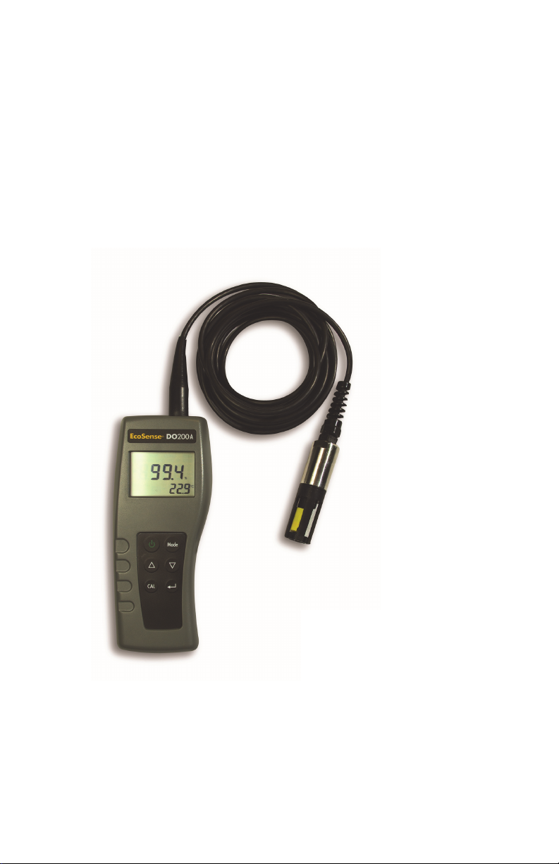
The DO200A is a precise tool that measures temperature and dissolved oxygen in % and
ppm (mg/L) .
This instrument has a waterproof IP67 case when the connector cap is installed. The keys are
highly reliable with tactile and audio feedback. This instrument uses one 9V battery. Recalibration is not required after turning the instrument off and on.
The front of the instrument has a large LCD that displays DO %, ppm, and temperature
simultaneously along with user prompts and mode indicators. The unit prompts the user
through calibration and measurement procedures.
The model DO200A field and lab probes use a polarographic electrode with convenient
screw-on cap membranes. The 200-4 and 200-10 field probes come with a built-in
temperature probe for automatic temperature compensation, as well as a stainless steel body
for added weight. The self stirring 200-BOD lab probe comes with a power supply and has
replaceable electrodes.
Other features include long battery life and high 50/60 Hz AC noise rejection. This instrument
is universal and user-friendly for field, industrial, and laboratory applications.
INITIAL INSPECTION
Carefully unpack the unit and accessories, and inspect for shipping damages. Compare
received parts with materials listed on the packing list. Notify YSI immediately of any damage
or missing parts. Save all packing materials until satisfactory operation is confirmed.
PRECAUTIONS
The Case
Though the instrument is housed in a water-proof IP67 case, DO NOT use it underwater. The
connector is not waterproof unless the cap is installed. In case of submersion without the cap
connected, follow these steps immediately:
1. Dry the connector if necessary. Rinse unit carefully with distilled water. After rinsing and
drying, inspect and clean connectors to remove all contaminants that may affect probe
connections.
2. Wait for unit and connectors to dry completely before resuming operation.
3. If the unit does not function correctly after steps 1 and 2, call YSI for possible repair or
replacement.
The Probes (Field & Lab)
1. Membranes last longer if properly installed and regularly maintained. Erratic readings
can result from damaged or fouled membranes or from large bubbles in the electrolyte
reservoir. If unstable readings or membrane damage occurs, replace both the
membrane cap and Oxygen Probe solution (O2 Probe Electrolyte). The average
membrane replacement interval is 4 to 8 weeks, although they may last longer if kept
clean. Harsh environments, such as wastewater, may require membrane replacement
every 2 to 4 weeks. Unstable readings may occur if membrane cap is coated with oxygen
consuming or producing organisms such as bacteria or algae.
2. Chlorine, sulfur dioxide, nitric oxide and nitrous oxide can affect readings by behaving
like oxygen at the probe.
3. Avoid substances that may damage probe materials such as concentrated acid, caustics
and strong solvents. Probe materials include Stainless steel, epoxy and ABS Plastic.
4. Keep the probe’s gold cathode clean and textured (when properly maintained it has a
matte finish). If it is tarnished (from contact with certain gases), or plated with silver (from
extended use with a loose or wrinkled membrane), then clean it, following the
instructions in “Probe Maintenance”.
3
Page 5
5. To prevent the membrane and electrolyte from drying out, store the field probe in the
A
calibration bottle with the moistened, clean sponge and the lab probe in a clean BOD
bottle with 1 inch of water to keep them in a saturated air environment.
PROBE PREPARATION
The DO200A probe ships with a dry, protective membrane. To install a new membrane cap
on the probe:
1. Unscrew probe membrane cap and discard.
2. Fill a new cap with Oxygen Probe Solution. If using the probe solution for the first time,
prepare it according to directions on the bottle.
3. Thread filled membrane cap onto sensor.
4. Allow sufficient warm-up time for initial use (10-15 min). During this time an “ovEr”
message may appear on the display. This is normal. After the warm up is complete the
message will disappear.
BATTERY INSTALLATION
An initial display of “LOW BAT” on the LCD indicates
approximately one hour of battery life for unit operation within
specifications. Replace battery when “LOW BAT” appears on
the LCD.
To replace battery, remove the two battery cover screws and
the
battery cover and o-ring. Replace the 9V battery. Replace the
battery cover and o-ring (be sure to align the o-ring correctly to
prevent a bad seal) and fasten the two battery cover screws for
Figure 1.
Battery Installation
the water-proof feature.
Battery Disposal
This instrument is powered by a 9 volt battery, which the user must remove and dispose of
when the batteries no longer power the instrument. Disposal requirements vary by country
and region, and users are expected to understand and follow the battery disposal
requirements for their specific locale.
THE KEYPAD
1. : Turns the unit on or off.
2. MODE: In normal operation, toggles display between Dissolved Oxygen in % air
saturation, Dissolved Oxygen in ppm (mg/L), Delete and Recall. In Calibration mode,
exits current calibration and displays the next calibration parameter.
3. CAL: In normal operation, changes the mode from Normal to Calibration. See
Calibration Set-up.
: In Calibration Set-up, press this key to save the current parameter to memory.
4.
5. and Keys: Increases or decreases the display value as desired.
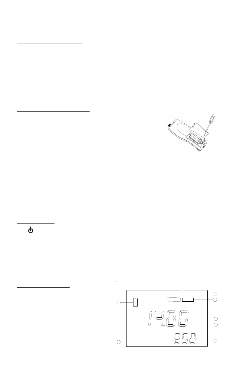
THE LCD DISPLAY
1. BAT: Low battery indicator.
2. CAL: Calibration mode indicator.
3. SAL ppt: Displays during calibration
when user is prompted for the
approximate salinity of the sample in
parts per thousand (ppt).
4. mBar: Displays during calibration to
prompt user for barometric pressure.
5. Main display for dissolved oxygen
values.
6. %/ppm: Unit indicators.
1
2
4
BAT
CAL
Figure2. LCD Display
SAL ppt
mBar
% ppm
C
3
4
5
6
7
Page 6

7. ºC: Temperature display.
OPERATIONAL PROCEDURES
Press to turn the unit on or off. The instrument will perform a self-diagnostic test, during
which an “ovEr” message may appear on the display. This is normal. After the warm up is
complete the message will disappear. After the self-diagnostic test completes, the
temperature displays in the lower right of the display, and the unit is ready for operation.
Immerse the probe into the sample solution. If possible, do not allow probe to touch any solid
object in the solution. Avoid air bubbles bursting on the membrane surface. When the unit is
not in use, turn it off to save battery life. The instrument has a 30 minute auto shut off feature
when not in use.
NOTE: During an oxygen measurement, the probe must be moved approximately 1/2 ft per
second to overcome the consumption of oxygen by the sensor. When using the 200-BOD lab
probe, however, simply use the probe’s self-stirring feature.
MEASUREMENT MODES
This unit provides three distinct measurements:
1. Temperature - Current solution temperature continually displays.
2. Dissolved Oxygen % - Measurement of oxygen in percent saturation.
3. Dissolved Oxygen ppm - Measurement of oxygen in ppm (mg/L).
Carefully observe the units displayed at the far side of the LCD to determine the desired
mode.
SAVING, VIEWING AND DELETING DATA
The DO200A can save 50 data records. When in measurement mode, press to save a
record. The instrument will confirm the saved data by displaying SAVE and the record
number for one second. “Full” is displayed when trying to save data and the memory is full.
To view saved data, press mode until RECALL is displayed and then press . Use the Up or
Down arrow keys to review different saved records. Press Mode to escape back to
measurement mode.
To delete data records, press Mode while in measurement mode until DELETE is displayed.
Press . “All” will be displayed and blinking. Press the Up or Down arrow key to switch
between delete ‘All’ or ‘Each’ options. Select either ‘All’ or ‘Each’ by pressing while that
option is displayed.
If ‘All’ is selected, all records will be deleted from memory and ‘None’ will be displayed. Press
Mode twice to return to the measurement mode.
If ‘Each’ is selected, the Up and Down arrow keys will allow you to scroll through the saved
data records. Press to delete the selected record. All records after the deleted record will
shift up to keep the records in sequential order. For example, if record 3 is deleted, record 4
will become record 3 and record 5 will become record 4. Press Mode twice to return to the
measurement mode.
CALIBRATION SET-UP
Requirements
1. The approximate pressure (in millibars [mBar]) of the location at the time of calibration.
2. The approximate salinity of the water to be analyzed. Fresh water has an approximate
salinity of zero parts per thousand (ppt). Seawater has an approximate salinity of 35 ppt.
Procedure
1. For the field probe, place 5-6 drops of clean water (tap, distilled, or deionized) into the
sponge inside the calibration bottle. Turn the bottle over and allow any excess water to
drain out of the bottle. The wet sponge creates a 100% water-saturated air environment
5
Page 7

for the probe, which is ideal for calibration, transport, and storage of the Model DO200A
probe. For calibration, the probe remains in a water saturated air atmosphere and is not
submersed.
For the lab probe, simply use the same bottle the probe is stored in with approximately
1 inch of water in the bottom. This creates a 100% water-saturated air environment for
the probe, which is ideal for calibration and storage of the Model 200-BOD probe. For
calibration, the probe remains in a water saturated air atmosphere and is not
submersed.
2. For the field probe, slide it into the calibration bottle. Be sure the membrane does not
touch the sponge.
3. Turn on the DO200A by pressing . Wait 10 to 15 minutes for the dissolved oxygen and
temperature readings to stabilize.
4. Press CAL.
5. The LCD prompts for the local pressure in mBar. Use the and keys to increase or
decrease the pressure value respectively. See the section titled ‘Conversions’ to convert
barometric pressure units to mBars.
6. When the proper pressure displays, press
lower right of the display. Once the value in the main display stabilizes, press
move to the salinity compensation procedure.
7. The display prompts for the approximate salinity of the water to be analyzed. Use the
and keys to increase or decrease the salinity compensation value to the value of your
sample (between 0 to 40 parts per thousand [ppt]). When the correct salinity displays,
.
press
8. The unit holds calibration even if it is powered off. However, it is recommended to check
calibration with each use and recalibrate as necessary to prevent drift. Dissolved oxygen
readings are only as good as the calibration.
once to view the calibration value in the
again to
PROBE MAINTENANCE
Clean the probe whenever it won’t calibrate or the readings are unstable and changing the
membrane does not solve either issue. On average, the probe should only be cleaned about
once or twice per year. To clean the probe, sand the electrodes according the directions
below. In addition to sanding, a chemical soak may be necessary (direction below). Always
sand the electrodes after performing a chemical soak.
1. Turn unit off, or disconnect probe.
2. Remove membrane cap and rinse the probe with clean water (tap, distilled, or
deionized).
3. Obtain either:
14 % lab strength ammonium hydroxide and soak for 2-3 minutes
4. Rinse ammonium hydroxide/ammonia completely from probe.
5. Use sandpaper (400 grit wet/dry, supplied with 5238 kit and with the 5908 membrane
6. Install a new membrane cap.
Never use chemicals or abrasives not recommended by YSI.
3% household cleaning strength ammonia and soak overnight (8-12 hours)
kit) to buff (wet sand) excess deposits from probe. Perform a circular sand on the gold
cathode (tip) and also wrap the sand paper around the silver anode (shaft) and twist.
Rinse with clean water (tap, distilled, or deionized).
6
Page 8

TROUBLESHOOTING
Y
Y
Main Display reads: Possible Solutions:
“ovEr” or “undr”
Check membrane and electrolyte solution.
Clean anode and cathode.
Return product for service.
Secondary Display reads: Possible Solutions:
“undr”
“ovEr”
Heat the sample to above –6.0 °C
Return product for service.
Cool sample to below 46.0 °C
Return product for service
SPECIFICATIONS
Display Range Accuracy Resolution
Dissolved O2
(ppm or mg/L)
Dissolved O2
% air-sat
Temperature °C -6.0 to 46.0 °C
Pressure Compensation 600 to 1100 mBar (450 to 825 mmHg)
Salinity Compensation From 0.0 to 40.0 ppt
ATC Probe
Calibration Backup
Audio Feedback
Power Source One 9V battery
Operating Temperature
Instrument Casing Waterproof IP 67
Weight (with battery) 270 grams (.61 lbs)
Dimensions (L x W x D) 18.7 cm x 7.6 cm x 3.8 cm (7.3 in x 3 in x 1.5 in)
0 to 20.00 ppm (mg/L) ±2 % of the reading or ±2% air
0 to 200.0 % ±2% of the reading or ±0.2 ppm,
21 to 115 °F
saturation, whichever is greater
whichever is greater.
±0.3 °C ±1 digit 0.1 °C
Thermistor, 10K, at 25C
es
es, on all keys
0 to 50C (32 to
122 °F)
0.01 mg/L
0.1 %
CONVERSIONS
To Convert: Multiply by:
Inches of Hg to mBar 33.864
Inches of Hg to mmHg 25.4
mmHg to mBar 1.333
RECOMMENDED SPARE PARTS LIST
PART # DESCRIPTION
200-4 4 meter (approx. 13 feet) probe and cable assembly
200-10 10 meter (approx. 33 feet) probe and cable assembly
200-BOD Self-stirring BOD lab probe and cable assembly with power supply
485 DO carrying case, soft sided
606036 DO carrying case, hard sided
5908 Membrane kit, 1.25 mil PE (605306), six cap membranes and KCl solution
Item #606035REF
Revision A; July 2012
For the latest version of this manual, visit www.ysi.com
7
Page 9

GARANTIE
L’appareil EcoSense® DO200A est garanti pour une période d’un an, à compter de la date
d’achat par l’utilisateur final, contre tout défaut matériel et de fabrication. Les sondes et les
câbles de DO200A sont garantis pour une période d’un an, à compter de la date d’achat par
l’utilisateur final, contre tout défaut matériel et de fabrication. Pendant la période de garantie,
YSI s’engage à réparer ou à remplacer, gratuitement et à sa discrétion, tout produit qu’YSI
peut établir comme étant couvert par la garantie.
Pour faire valoir cette garantie, écrivez ou appelez votre représentant YSI ou contactez le
Service clientèle d’YSI à Yellow Springs, Ohio, États-Unis. Envoyez le produit et son justificatif
d’achat en port payé au Centre de service homologué sélectionné par YSI. La réparation ou le
remplacement seront effectués et le produit vous sera retourné en port payé. Les produits
réparés ou remplacés sont garantis jusqu’à expiration de la période de garantie originale ou
au moins 90 jours à compter de la date de réparation ou de remplacement.
Limitation de garantie
Cette garantie ne s’applique pas aux produits YSI endommagés ou présentant des
dysfonctionnements pour les raisons suivantes : (i) installation, exploitation ou utilisation du
produit d’une façon non conforme aux instructions écrites d’YSI ; (ii) abus ou mésusage du
produit ; (iii) manquement à l’entretien du produit conformément aux instructions écrites
d’YSI ou aux procédures industrielles normales ; (iv) réparation non conforme du produit ; (v)
utilisation par vous de pièces ou de composants défectueux ou non conformes lors de
l’entretien ou de la réparation du produit ; ou, (vi) modification du produit d’une façon non
expressément autorisée par YSI.
CETTE GARANTIE REMPLACE TOUTES LES AUTRES GARANTIES, EXPRESSES OU INDUITES,
Y COMPRIS LES GARANTIES DE COMMERCIABILITÉ OU D’ADAPTATION À UN USAGE
PARTICULIER. LA RESPONSABILITÉ D’YSI SELON LES TERMES DE CETTE GARANTIE SE
LIMITE À LA RÉPARATION OU AU REMPLACEMENT DU PRODUIT, CONSTITUANT VOTRE
SEUL ET UNIQUE RECOURS POUR TOUT PRODUIT DÉFECTUEUX COUVERT PAR CETTE
GARANTIE. YSI NE POURRA EN AUCUN CAS ÊTRE TENU RESPONSABLE DE DOMMAGES
SPÉCIAUX, INDIRECTS, ACCIDENTELS OU CONSÉCUTIFS RÉSULTANT DE L’UTILISATION DE
TOUT PRODUIT DÉFECTUEUX COUVERT PAR CETTE GARANTIE.
COMMENT NOUS CONTACTER
YSI
1725 Brannum Lane
Yellow Springs OH, 45387, États-Unis
800-897-4151 • 937-767-7241 • Télécopie : 937-767-1058
E-mail : environmental@ysi.com
Web : www.ysi.com
1
Page 10

TABLE DES MATIÈRES
GARANTIE .............................................................................................................. 1
TABLE DES MATIÈRES ......................................................................................... 2
INFORMATIONS GÉNÉRALES ............................................................................ 3
INSPECTION INITIALE .......................................................................................... 3
PRÉCAUTIONS ...................................................................................................... 3
PRÉPARATION DE LA SONDE ............................................................................ 4
INSTALLATION DE LA PILE ................................................................................. 4
CLAVIER ................................................................................................................. 4
ÉCRAN À CRISTAUX LIQUIDES .......................................................................... 5
PROCÉDURES D’UTILISATION ........................................................................... 5
MODES DE MESURE ............................................................................................ 5
ENREGISTREMENT, AFFICHAGE ET SUPPRESSION DES DONNÉES ........... 5
CONFIGURATION DE L’ÉTALONNAGE ............................................................ 6
ENTRETIEN DE LA SONDE .................................................................................. 7
DÉPANNAGE ......................................................................................................... 7
SPÉCIFICATIONS .................................................................................................. 8
CONVERSIONS ..................................................................................................... 8
LISTE DES PIÈCES DÉTACHÉES RECOMMANDÉES ........................................ 8
2
Page 11

INFORMATIONS GÉNÉRALES
L’ DO200A est un outil de précision mesurant l’oxygène dissous en pourcentage, ppm (mg/l)
ainsi que sa température. Un microprocesseur incorporé stocke, calcule et compense tous les
paramètres relatifs aux déterminations liées à l’oxygène dissous, y compris les
caractéristiques de température des électrodes de détection de l’oxygène dissous.
Cet appareil est étanche (IP67) uniquement lorsque le capuchon recouvre le connecteur est
branché. Les touches mécaniques sont très fiables et fournissent une réaction tactile et
sonore. Cet appareil utilise une pile de 9 V. Aucun réétalonnage n'est nécessaire lorsque
l'alimentation électrique est rétablie
L’avant de l’appareil dispose d’un écran à cristaux liquides affichant simultanément le
pourcentage, les mg/l et la température de l’oxygène dissous, ainsi que les invites destinées à
l’utilisateur et les indicateurs de mode. L’appareil émet des invites destinées à l’utilisateur lors
des procédures d’étalonnage et de mesure.
Le modèle de sonde de terrain et de laboratoire DO200A utilise une électrode
polarographique disposant de capuchons à membrane vissables. Les sondes de terrain 200-4
et 200-10 sont équipées d’une sonde de température incorporée permettant la
compensation automatique de la température, ainsi que d’un corps en acier inoxydable qui
en augmente la masse. La sonde de laboratoire 200-BOD est équipée d’un bloc
d’alimentation électrique et comporte des électrodes remplaçables auto-agitées.
Parmi les autres caractéristiques, on notera la longue durée de vie des piles et une
élimination du bruit élevée de 50/60 Hz c.a. Cet appareil est convivial et particulièrement
souple dans les applications sur le terrain, industrielles et en laboratoire.
INSPECTION INITIALE
Déballez soigneusement l’appareil et les accessoires et vérifiez qu’ils n’ont pas été
endommagés lors de l’expédition. Comparez les pièces reçues aux matériaux répertoriés
dans le bordereau d’emballage. Notifiez immédiatement YSI s’il s’avère que des pièces sont
endommagées ou manquantes. Mettez de côté les matériaux d’emballage jusqu’à ce que le
fonctionnement correct de l’appareil soit confirmé.
PRÉCAUTIONS
Boîtier
L'appareil est en effet protégé par un boîtier étanche IP67, mais NE doit PAS être utilisé sous
l'eau. Le connecteur n’est pas étanche, sauf si le capuchon le recouvre. En cas d’immersion
sans capuchon, suivre immédiatement les étapes suivantes:
1. Séchez le connecteur, le cas échéant, et remplacez la sonde d’oxygène dissous. Rincez
soigneusement l’appareil avec de l’eau distillée. Après le rinçage et le séchage,
inspectez et nettoyez les connecteurs en vue d’éliminer tout contaminant pouvant
affecter les connexions de la sonde.
2. Attendez que l’appareil et la sonde soient parfaitement secs avant de reprendre les
opérations.
3. Si l’appareil ne fonctionne pas correctement après les étapes 1 et 2, appelez YSI en vue
d’une réparation ou d’un remplacement éventuels.
Les sondes (de terrain et de laboratoire)
1. Les membranes durent plus longtemps si elles sont correctement installées et
entretenues régulièrement. Des membranes endommagées ou sales et des grosses
bulles dans le réservoir d’électrolyte peuvent entraîner des lectures incohérentes. Si les
lectures sont instables ou la membrane endommagée, remplacez le capuchon à
membrane et la solution de la sonde à oxygène (également appelée « Électrolyte de
sondage d’oxygènométrie », chlorure de potassium ou solution KCl). Les intervalles de
remplacement sont habituellement de 4 à 8 semaines, bien qu’ils puissent se prolonger
s’ils sont conservés en bon état de propreté. Les milieux particulièrement difficiles, tels
que les eaux usées, peuvent exiger que la membrane soit remplacée toutes les 2 à 4
semaines. Des lectures instables peuvent avoir lieu si le capuchon à membrane est
3
Page 12

recouvert d’organismes consommant ou évoluant dans l’oxygène, tels que des bactéries
ou des algues.
2. Le chlore, l’anhydride sulfureux, le monoxyde d’azote et l’oxyde nitreux peuvent affecter
les lectures en se comportant comme de l’oxygène au niveau de la sonde.
3. Évitez les produits pouvant endommager les matériaux de la sonde, tels que l’acide
concentré et les solvants puissants et caustiques. Les matériaux de la sonde comportent
de l’acier inoxydable, de l’adhésif époxyde et du plastique ABS.
4. Gardez la cathode dorée de la sonde en bon état de propreté et texturée (lorsqu’elle est
correctement entretenue, elle présente un fini mat). Si elle se ternit (après être entrée en
contact avec certains gaz) ou présente un aspect argenté (en raison d’une utilisation
prolongée avec une membrane lâche ou plissée), nettoyez-la en suivant les instructions
de la section « Entretien de la sonde ».
5. Pour éviter que la membrane et l’électrode se dessèchent, stockez la sonde de terrain
dans la bouteille d’étalonnage avec l’éponge humide et la sonde de laboratoire dans un
flacon BOD avec 2,5 cm (1 po) d’eau pour les conserver dans un milieu saturé.
PRÉPARATION DE LA SONDE
La sonde DO200A est fournie avec une membrane protectrice sèche. Pour installer un
nouveau capuchon à membrane sur la sonde :
1. Dévissez le capuchon à membrane de la sonde et jetez-le.
2. Remplissez un nouveau capuchon de solution de sondage d’oxygénométrie. Effectuez la
préparation conformément aux instructions de la bouteille de solution.
3. Enfilez le capuchon à membrane rempli sur le capteur.
4. Laissez l’ensemble se réchauffer suffisamment longtemps lors de la première utilisation
(10 à 15 minutes). Il se peut que le message « ovEr » s’affiche pendant ce temps sur
l’écran. Cette condition est normale. Le message disparaîtra une fois le chauffage
terminé.
INSTALLATION DE LA PILE
Lorsque l’écran à cristaux liquides affiche pour la première fois
« LOW BAT », il reste environ une heure de fonctionnement sur pile
selon les spécifications. Remplacez la pile lorsque l’indication « LOW
BAT » s’affiche sur l’écran.
Pour remplacer la pile, enlevez les deux vis du compartiment ainsi
que le couvercle et le joint torique. Remplacez la pile de 9 V.
Replacez le couvercle et le joint torique (veillez à aligner le joint
correctement afin d’assurer une bonne étanchéité) et revissez les
deux vis du compartiment pour conserver une bonne résistance aux
éclaboussures.
Figure 1.
Installation de la
pile
Mise au rebut des piles
L’appareil est alimenté par des piles alcalines que l’utilisateur doit retirer et jeter lorsque les
piles n’alimentent plus l’appareil. Les exigences concernant la mise au rebut sont différentes
en fonction du pays et de la région, et il est attendu de l’utilisateur qu’il comprenne et suive
les règlements spécifiques à sa juridiction concernant la mise au rebut des piles.
CLAVIER
1. : Met l’appareil hors ou sous tension.
2. MODE : Défilement de l’affichage en service normal : oxygène dissous en pourcentage
de saturation de l'air, oxygène dissous en ppm (mg/l), Supprimer, Rappeler. En mode
d'étalonnage, quitte l'étalonnage actuel et affiche le paramètre d'étalonnage suivant.
3. CAL : En fonctionnement normal, passe du mode Normal au mode Étalonnage
(Calibration). Voir la section Configuration de l’étalonnage.
: Lors de la configuration de l’étalonnage, appuyez sur cette touche pour enregistrer
4.
le paramètre actuel en mémoire.
5. Touches et : Augmentent ou diminuent la valeur affichée, comme voulu.
4
Page 13

ÉCRAN À CRISTAUX LIQUIDES
A
1. BAT : Indicateur de pile déchargée.
2. CAL : Indicateur de mode
d’étalonnage (Calibration).
3. SAL ppt : S’affiche lors de
3
1
BAT
SAL ppt
mBar
4
l’étalonnage pour inviter l’utilisateur à
indiquer la salinité approximative de
l’échantillon, exprimée en parties par
millier (ppt).
4. mBar : S’affiche lors de l’étalonnage
pour inviter l’utilisateur à indiquer la
pression barométrique.
5. Affichage principal des valeurs de
l’oxygène dissous.
2
CAL
Figure 2. Écran à cristaux liquides
% ppm
5
6
C
7
6. %/ppm : Indicateurs d’unité.
7. ºC : Affichage de la température.
PROCÉDURES D’UTILISATION
Appuyez sur pour mettre l’appareil hors ou sous tension. L’appareil exécutera un test
d’autodiagnostic pendant lequel le message « ovEr » peut s’afficher sur l’écran. Cette
condition est normale. Le message disparaîtra une fois le chauffage terminé. Une fois que le
test d’autodiagnostic est terminé, la température s’affiche dans la partie inférieure droite de
l’écran et l’appareil est prêt à être utilisé. Plongez la sonde à mi-hauteur dans la solution de
l’échantillon. Si possible, ne laissez pas la sonde toucher un objet quelconque dans la
solution. Ne laissez aucune bulle se former autour de la sonde. Lorsque l’appareil n’est pas
utilisé, mettez-le hors tension pour économiser la pile. L’appareil s’éteint automatiquement
s’il n’est pas utilisé après 30 minutes.
REMARQUE : Lors de la mesure de l’oxygène, la sonde doit être déplacée d’environ 15 cm
(1/2 pied) par seconde pour compenser la consommation d’oxygène inhérente du capteur.
Cependant, avec une sonde de laboratoire 200-BOD, utilisez simplement la fonction d’autoagitation des sondes.
MODES DE MESURE
Cet appareil permet trois mesures distinctes :
1. Temperature (Température) – La température actuelle de la solution s’affiche
constamment.
2. Dissolved Oxygen % (Pourcentage d’oxygène dissous) – Mesure de l’oxygène en
pourcentage de la saturation.
3. Dissolved Oxygen ppm (Mg/l d’oxygène dissous) – Mesure de l’oxygène en ppm
(mg/l).
Observez soigneusement les unités affichées à l’extrémité de l’écran à cristaux liquides pour
déterminer le mode voulu.
ENREGISTREMENT, AFFICHAGE ET SUPPRESSION DES DONNÉES
Le DO200A enregistre jusqu’à 50 jeux de données. En mode de mesure, appuyez sur pour
enregistrer un jeu. L’appareil confirmera l'enregistrement des données en affichant pendant
une seconde SAVE (Enregistrer) et le numéro du jeu. Si la mémoire est pleine, l’appareil
affiche « Full » (Pleine) lorsque vous essayez d’enregistrer des données.
Pour afficher des données enregistrées, appuyez sur Mode jusqu’à ce que RECALL (Rappeler)
s’affiche, puis appuyez sur. Parcourez alors les jeux enregistrés à l’aide des touches de
déplacement vers le haut ou vers le bas. Appuyez sur Mode pour revenir au mode de
mesure.
Pour supprimer des jeux de données, appuyez sur Mode en mode de mesure jusqu’à ce que
DELETE (Supprimer) s'affiche. Appuyez sur. « All » (Tous) s’affiche et clignote. À l’aide des
5
Page 14

touches de déplacement vers le haut ou vers le bas, passez de All (Tous) à Each (Chaque).
Appuyez sur pour valider l'option affichée (All ou Each).
Si vous choisissez All, tous les jeux seront supprimés de la mémoire et None (Aucun) sera
affiché. Appuyez deux fois sur Mode pour revenir au mode de mesure. Si vous sélectionnez
Each, faites défiler les jeux de données enregistrés avec les touches de déplacement vers le
haut ou vers le bas. Appuyez sur pour supprimer le jeu sélectionné. La suppression d’un
jeu modifie le classement des jeux suivants, de manière à garder les jeux en suite ordonnée.
Par exemple, si le jeu 3 est supprimé, le jeu 4 deviendra le jeu 3, le jeu 5 deviendra le no 4,
etc. Appuyez sur Mode pour revenir au mode de mesure
CONFIGURATION DE L’ÉTALONNAGE
Exigences Préalables
1. La pression barométrique réelle approximative (exprimée en millibars [mBar]) au
moment de l’étalonnage.
2. La salinité approximative de l’eau devant être analysée. L’eau douce a une salinité
approximative de zero ppt. L’eau de mer a une salinité approximative de 35 ppt.
Procédure
1. Avec la sonde de terrain, déposez 5 ou 6 gouttes d’eau propre (courante, distillée ou
désionisée) sur l’éponge, à l’intérieur de la bouteille d’étalonnage. Renversez la bouteille
et laissez toute eau en excès s’écouler hors de la bouteille. L’éponge humide permet
d’obtenir un milieu atmosphérique saturé à 100 % d’humidité pour la sonde, ce qui est
optimal pour l’étalonnage et le stockage de la sonde du modèle DO200A. Pour
l’étalonnage, la sonde reste dans une atmosphère saturée d’humidité et n’est pas
immergée.
Avec la sonde de laboratoire, utilisez simplement la bouteille de stockage de la sonde
avec environ 2,5 cm (1 po) d’eau au fond. Cela permet d’obtenir un milieu
atmosphérique saturé à 100 % d’humidité pour la sonde, ce qui est optimal pour
l’étalonnage et le stockage de la sonde du modèle 200-BOD. Pour l’étalonnage, la
sonde reste dans une atmosphère saturée d’humidité et n’est pas immergée.
2. Avec la sonde de terrain, glissez-la dans la bouteille d’étalonnage. Veillez à ce que la
membrane ne touche pas l’éponge.
3. Mettez le modèle DO200A sous tension en appuyant sur . Attendez 10 à 15 minutes
que les lectures de l’oxygène dissous et de la température se stabilisent.
4. Appuyez sur CAL.
5. L’écran vous invite à indiquer la pression atmosphérique locale, exprimée en mBar.
Utilisez les touches et , respectivement, pour augmenter ou diminuer la valeur de la
pression. Reportez-vous à la section intitulée « Conversions » pour convertir les unités de
pression barométriques en mBar.
6. Lorsque la pression voulue est affichée, appuyez une fois sur
d’étalonnage dans la partie inférieure droite de l’écran. Une fois que la valeur affichée
dans l’écran principal se stabilise, appuyez à nouveau sur
de compensation de la salinité.
7. L’écran vous invite à indiquer la salinité approximative de l’eau devant être analysée.
Utilisez les touches et pour augmenter ou diminuer la valeur de compensation de la
salinité afin qu’elle corresponde à la valeur de l’échantillon (entre 0 et 40 parties par
millier [ppt]). Une fois que la salinité correcte est affichée, appuyez sur
8. L’appareil retient l’étalonnage même s’il est mis hors tension. Cependant, nous vous
recommandons de vérifier l’étalonnage à chaque utilisation et de réaliser un nouvel
étalonnage, le cas échéant, afin d’éviter toute déviation. La validité des lectures
d’oxygène dissous dépend d’un bon étalonnage.
pour afficher la valeur
pour passer à la procédure
.
6
Page 15

ENTRETIEN DE LA SONDE
Pour nettoyer les sondes, utilisez le kit YSI de reconditionnement de sonde (YSI Probe
Reconditioning kit) (numéro de référence 5238). Avec la sonde de laboratoire, utilisez le
disque abrasif fourni dans le kit de membrane 5908 et suivez les consignes de nettoyage
décrites dans le manuel de la sonde 200-BOD concernant le ponçage. En plus du kit de
reconditionnement et du disque abrasif fourni dans le kit de membrane 5908, un nettoyage
chimique peut s’avérer utile. Pour effectuer un nettoyage chimique de la sonde, trempez-la
dans de l’ammoniaque.
1. Enlevez le capuchon à membrane et rincez la sonde avec de l’eau propre (courante,
distillée ou désionisée).
2. Mettez l’appareil hors tension ou déconnectez la sonde.
3. Obtenez soit :
de l’ammoniaque de laboratoire à 14 % et laissez tremper la sonde 2 ou 3 minutes
de l’ammoniaque de nettoyage domestique à 3 % et laissez tremper la sonde de 8
à 12 heures.
4. Rincez la sonde de toute trace d’ammoniaque.
5. Utilisez le papier de verre (n° 400 sec/mouillé, fourni avec le kit 5238 et avec le kit de
membrane 5908) pour poncer à l’eau la sonde et éliminer tout dépôt restant.
6. Installez un nouveau capuchon à membrane.
N’utilisez jamais de produits chimiques ou abrasifs non recommandés par YSI.
DÉPANNAGE
L’écran principal affiche : Solutions possibles :
« ovEr » ou « undr »
L’écran secondaire affiche : Solutions possibles :
« undr »
« ovEr »
Vérifiez la membrane et la solution d’électrolyte.
Nettoyez l’anode et la cathode.
Retournez le produit au centre de service.
Réchauffez l’échantillon pour que sa température soit
supérieure à -6,0 °C
Retournez le produit au centre de service.
Refroidissez l’échantillon pour que sa température
soit inférieure à 46,0 °C
Retournez le produit au centre de service.
7
Page 16

SPÉCIFICATIONS
Affichage Fourchette Précision Résolution
Oxygène dissous
(ppm ou mg/l)
Oxygène
dissous,
pourcentage de
la saturation
de l’air
Température °C
(°F)
Compensation de la pression 600 à 1100 mBar (450 à 825 mmHg)
Compensation de la salinité
Sonde CAT
0 à 20,00 ppm (mg/l) Le plus grand de ±2 % de la
0 à 200,0 % Le plus grand de ±2% de la
-6,0 à 46,0 °C
(21 à 115 °F)
De 0,0 à 40,0 x 10
lecture ou ±2 % de la saturation
lecture ou ±0,2 ppm (mg/l)
de l’air
±0,3 °C ±1 chiffre 0,1 °C
-3
Thermistor, 10 K, à 25 C
0,01 mg/l
0,1 %
Sauvegarde de l’étalonnage Oui
Touches sonores Oui, toutes les touches
Source d’alimentation Une pile de 9 V
Température de
0 à 50 °C (32 à 122 °F)
fonctionnement
Boîtier de l’appareil
Étanche, norme IP 67
Poids (avec pile) 270 g (0,61 de livre)
Dimensions (L x P x H) 18.7 cm x 7.6 cm x 3.8 cm (7,4 po x 3 po x 1,5 po)
CONVERSIONS
Pour convertir : Multiplier par :
Pouces de mercure en mBar 33,864
Pouces de mercure en mmHg 25,4
mmHg en mBar 1,333
LISTE DES PIÈCES DÉTACHÉES RECOMMANDÉES
N° RÉF. DESCRIPTION
200-4 Assemblage, câble de 4 mètres (environ 13 pieds) et sonde
200-10 Assemblage, câble de 10 mètres (environ 33 pieds) et sonde
200-BOD Sonde BOD de laboratoire auto-agitante et câblage avec bloc d’alimentation
606036 Sacoche de transport DO, flancs durs
5908
485 Sacoche de transport de l’appareil, souple
Kit de membrane, PE de 31,75 μm (1,25 millième de pouce) d’épaisseur
(605306), six capuchons à membrane et solution KCl
Article n° 606035REF
Révision A ; Juillet 2012
Pour la dernière version de ce manuel, visite www.ysi.com
8
Page 17

GARANTÍA
El medidor EcoSense® DO200A tiene un año de garantía contra defectos de materiales y
fabricación, contado a partir de la fecha de compra por el usuario final. Las sondas y cables
del medidor DO200A tienen un año de garantía contra defectos de materiales y fabricación,
contado a partir de la fecha de compra por el usuario final. Durante el período de garantía,
YSI reparará o reemplazará, según su criterio, sin coste alguno, cualquier producto que YSI
determine que está cubierto por esta garantía.
Para hacer valer esta garantía, escriba o llame al representante local de YSI, o comuníquese
con el Servicio de atención al cliente de YSI en Yellow Springs, Ohio, EE.UU. Envíe el
producto y la factura de compra, con el flete prepagado, al centro de servicio técnico
autorizado seleccionado por YSI. Se realizará la reparación necesaria o el reemplazo y el
producto será enviado de vuelta, con el flete prepagado. Los productos reparados o
reemplazados se garantizan durante el resto del período de la garantía original, o al menos
durante 90 días contados a partir de la fecha de reparación o reemplazo.
Limitación de la garantía
Esta garantía no tendrá validez en caso de daños o fallos en el producto de YSI debido a lo
siguiente: (i) la instalación, funcionamiento o utilización del producto de manera contraria a
las instrucciones escritas suministradas por YSI; (ii) abuso o uso inadecuado del producto; (iii)
falta de mantenimiento del producto de acuerdo con las instrucciones escritas suministradas
por YSI o con los procedimientos estándar de la industria; (iv) cualquier reparación indebida
realizada en el producto; (v) utilización por parte del usuario de componentes o repuestos
defectuosos o inadecuados para el mantenimiento o reparación del producto; o (vi)
cualquier modificación del producto no autorizada de manera expresa por YSI.
ESTA GARANTÍA SE OTORGA EN LUGAR DE CUALQUIER OTRA GARANTÍA, EXPLÍCITA O
IMPLÍCITA, LO QUE INCLUYE TODA GARANTÍA DE COMERCIALIZACIÓN O IDONEIDAD
PARA UN PROPÓSITO ESPECÍFICO. DE CONFORMIDAD CON ESTA GARANTÍA, LA
RESPONSABILIDAD DE YSI SE LIMITA A LA REPARACIÓN O REEMPLAZO DEL PRODUCTO,
LO CUAL SERÁ LA SOLUCIÓN ÚNICA Y EXCLUSIVA QUE TENDRÁ EL COMPRADOR POR
CUALQUIER PRODUCTO DEFECTUOSO CUBIERTO POR ESTA GARANTÍA. EN NINGÚN
CASO, YSI SERÁ RESPONSABLE POR NINGÚN DAÑO CUANTIFICABLE, INDIRECTO,
INCIDENTAL O CONSIGUIENTE QUE RESULTARA DE ALGÚN PRODUCTO DEFECTUOSO
CUBIERTO POR ESTA GARANTÍA.
INFORMACIÓN DE CONTACTO
YSI
1725 Brannum Lane
Yellow Springs OH, 45387, EE.UU.
800-897-4151 o 937-767-7241; Fax: 937-767-1058
Correo electrónico: environmental@ysi.com
Página en Internet: www.ysi.com
1
Page 18

CONTENIDO
GARANTÍA ............................................................................................................. 1
INFORMACIÓN DE CONTACTO ........................................................................ 1
PRESENTACIÓN GENERAL ................................................................................. 3
INSPECCIÓN INICIAL ........................................................................................... 3
PRECAUCIONES ................................................................................................... 3
PREPARACIÓN DE LA SONDA ........................................................................... 4
INSTALACIÓN DE LA PILA .................................................................................. 4
TECLAS ................................................................................................................... 4
PANTALLA DE CRISTAL LÍQUIDO ...................................................................... 5
INSTRUCCIONES DE FUNCIONAMIENTO ....................................................... 5
MODOS DE MEDICIÓN ....................................................................................... 5
CÓMO GUARDAR, VER Y BORRAR DATOS
AJUSTE DE LA CALIBRACIÓN ............................................................................ 6
MANTENIMIENTO DE LA SONDA ..................................................................... 7
LOCALIZACIÓN DE FALLOS ............................................................................... 7
ESPECIFICACIONES ............................................................................................. 7
CONVERSIONES ................................................................................................... 8
LISTA DE REPUESTOS RECOMENDADOS ....................................................... 8
.................................................. 5
2
Page 19

PRESENTACIÓN GENERAL
El medidor DO200A es un instrumento de precisión que mide el oxígeno disuelto
mostrándolo en porcentajes y en ppm (mg/L), y también mide la temperatura. Tiene un
microprocesador integrado que almacena, calcula y realiza la compensación de todos los
parámetros relacionados con la determinación del oxígeno disuelto, incluso, las
características de temperatura del electrodo de oxígeno disuelto.
Cuando está instalados la tapa conectora, el instrumento es a prueba de agua (IP67). Las
teclas de contacto mecánico son muy confiables y al pulsarlas proporcionan una respuesta
táctil y audible. Este instrumento utiliza una pila de 9 voltios. No requiere nueva calibración
cuando se restablece la corriente
La parte delantera del instrumento tiene una pantalla grande de cristal líquido que muestra
simultáneamente el oxígeno disuelto en valor porcentual, en partes por millón (ppm) y la
temperatura, junto con las indicaciones para el usuario y los indicadores del modo de
funcionamiento. La unidad orienta al usuario durante los procedimientos de calibración y
medición.
Las sondas de campo y de laboratorio modelo DO200A utilizan un electrodo polarográfico
con cápsulas prácticas de membrana enroscables. Las sondas de campo 200-4 y 200-10
cuentan con una sonda integrada para temperatura que realiza la compensación automática
de la temperatura, así como una estructura de acero inoxidable que proporciona más peso.
La sonda de laboratorio 200-BOD cuenta con alimentación de corriente e incluye
autoagitación y electrodos reemplazables.
Otras características incluyen una pila de larga duración y un mecanismo de eliminación de
ruido de 50/60 Hz CA. Este medidor es universal y fácil de usar en aplicaciones
industriales y de laboratorio.
.
in situ
,
INSPECCIÓN INICIAL
Saque la unidad de su embalaje con cuidado y verifique que no haya sufrido daños durante
el envío. Compare las piezas recibidas con los materiales enumerados en la lista de embalaje.
Notifique inmediatamente a YSI en caso de que haya piezas faltantes o dañadas. Guarde
todos los materiales de embalaje hasta que confirme que la unidad funciona
satisfactoriamente.
PRECAUCIONES
Estuche
Aunque el instrumento se encuentra en un estuche IP67 a prueba de agua, NO lo utilice bajo
agua. El conector no es a prueba de agua a menos que la tapa estén instalados. En caso de
sumergirlo sin la tapa o cable conectado, siga estos pasos inmediatamente.
1. Seque el conector, si es necesario, y cambie la sonda de oxígeno disuelto. Enjuague la
unidad cuidadosamente con agua destilada. Después del enjuague y secado, revise y
limpie los conectores para eliminar cualquier contaminante que pueda afectar las
conexiones de la sonda.
2. Espere hasta que la unidad y la sonda se sequen por completo antes de reanudar el
funcionamiento.
3. Si la unidad no funciona correctamente después de realizar los pasos 1 y 2,
comuníquese con YSI para su posible reparación o reemplazo (consulte la garantía).
Sondas (Campo y laboratorio)
1. Las membranas durarán más tiempo si se instalan correctamente y se les hace
mantenimiento con frecuencia. Pueden producirse lecturas erráticas si las membranas
están dañadas o sucias o si hay burbujas grandes en el depósito del electrólito. Si se
producen lecturas inestables o daños en la membrana, cambie tanto la cápsula de la
membrana como la solución de la sonda de oxígeno (también llamada “electrólito de la
sonda de O2”, cloruro potásico o solución KCl). En promedio, estos cambios deben
3
Page 20

hacerse cada 4 a 8 semanas, aunque la cápsula y la solución pueden durar más tiempo
si se mantienen limpias. En ambientes arduos, por ejemplo, en aguas residuales, puede
ser necesario cambiar la membrana cada 2 a 4 semanas. Pueden producirse lecturas
inestables si la cápsula de la membrana está recubierta de microorganismos que
consuman o transformen oxígeno, como las bacterias y las algas.
2. El cloro, el dióxido de azufre, el óxido nítrico y el óxido nitroso pueden afectar las
lecturas, ya que se comportan de manera similar al oxígeno en la sonda.
3. Evite las sustancias que puedan dañar los materiales de la sonda, tales como ácidos
concentrados, cáusticos y solventes fuertes. Los materiales de la sonda incluyen acero
inoxidable, epoxia y copolímeros acrilonitrilo, butadieno y estireno (ABS).
4. Mantenga el cátodo de oro de la sonda limpio y con la misma textura (cuando el
mantenimiento es adecuado, el acabado es mate). Si está manchado (por el contacto
con ciertos gases) o recubierto de plata (debido al uso prolongado con la membrana
floja o arrugada), deberá limpiarlo según las instrucciones de la sección “Mantenimiento
de la sonda”.
5. Para evitar que la membrana y el electrólito se sequen, almacene la sonda de campo en
la botella de calibración con la esponja húmeda y la sonda de laboratorio en una botella
BOD con 2,5 cm (1 pulgada) de agua para mantenerlas en un ambiente saturado de
aire.
PREPARACIÓN DE LA SONDA
La sonda del YSI DO200A viene con una membrana protectora seca. Instrucciones para
instalar una cápsula nueva en la membrana de la sonda:
1. Desenrosque la cápsula de la membrana de la sonda y deséchela.
2. Llene una nueva cápsula con solución para sondas de oxígeno. Prepare la solución de
acuerdo con las instrucciones de la botella.
3. Enrosque la cápsula llena en el sensor.
4. Deje que la solución se caliente antes de utilizarla por primera vez (de 10 a 15 minutos).
Durante este tiempo puede aparecer un mensaje “ovEr” en la pantalla. Esto es normal. El
mensaje desaparecerá cuando se haya completado el calentamiento.
INSTALACIÓN DE LA PILA
En la pantalla de cristal líquido aparecerá el mensaje de “LOW BAT”
(pila descargada) para indicar que queda aproximadamente una
hora de carga de la pila para el funcionamiento de la unidad según
las especificaciones. Cambie la pila cuando aparezca el mensaje
“LOW BAT” en la pantalla de cristal líquido.
Para cambiar la pila, saque los dos tornillos de la tapa y luego
retire la tapa y el aro tórico. Coloque una nueva pila de 9 voltios.
Vuelva a colocar la tapa y el aro tórico (asegúrese de alinear este
aro correctamente para garantizar un buen sellado) y ajuste los
dos tornillos de la tapa para que funcione la protección contra salpicaduras.
Figura 1.
Instalación de la batería
Eliminación de las pilas
Este instrumento funciona con pilas alcalinas que el usuario debe extraer y desechar cuando
ya no funcionen. Los requisitos de desechado varían según el país y la región, y se espera
que los usuarios entiendan y sigan los requisitos de desechado de pilas para su área
específica.
TECLAS
1. : Para encender y apagar la unidad.
2. MODE (MODO): Durante el funcionamiento normal, hace que la pantalla muestre
alternadamente el oxígeno disuelto en un porcentaje de aire saturado y en ppm (mg/L),
Borrar y Recordar. En el modo Calibración, sale de la calibración actual y muestra el
siguiente parámetro de calibración.
4
Page 21

3. CAL: Durante el funcionamiento normal, cambia el modo de Normal a Calibration
A
(Calibración). Consulte la sección “Ajuste de la calibración”.
4.
: En el ajuste de la calibración, pulse esta tecla para guardar en la memoria el
parámetro actual.
5. Teclas y : Para aumentar o disminuir el valor que aparece en la pantalla como sea
conveniente.
PANTALLA DE CRISTAL LÍQUIDO
1. BAT: Indicador de pila descargada.
2. CAL: Indicador del modo de
calibración.
3. SAL ppt: Aparece durante la
calibración cuando se pide al usuario
la salinidad aproximada de la muestra
en partes por millar (ppt).
4. mBar: Aparece durante la calibración
para pedir al usuario la presión
barométrica.
5. Pantalla principal que muestra los valores
del oxígeno disuelto.
6. %/ppm: Indicadores de la unidad.
7. ºC: Indicador de la temperatura.
1
2
BAT
SAL ppt
CAL
Figura 2. Pantalla de cristal líquido
mBar
% ppm
3
4
5
6
C
7
INSTRUCCIONES DE FUNCIONAMIENTO
Pulse la tecla para encender y apagar la unidad. El instrumento llevará a cabo una prueba
de autodiagnóstico, durante la cual puede aparecer un mensaje “ovEr” en la pantalla. Esto es
normal. El mensaje desaparecerá cuando se haya completado el calentamiento. Después de
completar la prueba de autodiagnóstico, aparecerá la temperatura en la parte inferior
derecha de la pantalla y la unidad estará lista para funcionar. Sumerja la sonda hasta la mitad
en la solución de muestra. A ser posible, no permita que la sonda haga contacto con ningún
objeto sólido en la solución. No permita que haya burbujas alrededor de la sonda. Cuando la
unidad no esté en uso, apáguela para ahorrar carga de la pila. El instrumento tiene una
función de apagado automático a los 30 minutos cuando no está en uso.
NOTA: Durante la medición de oxígeno, se debe mover la sonda unos 15 cm (1/2 pie) por
segundo para contrarrestar el consumo de oxígeno que hace el sensor. Sin embargo, cuando
se usa la sonda de laboratorio 200-BOD, utilice simplemente la característica de
autoagitación.
MODOS DE MEDICIÓN
Esta unidad realiza tres mediciones distintas:
1. Temperatura: la pantalla muestra constantemente la temperatura actual de la solución.
2. % de oxígeno disuelto: medición del oxígeno en porcentaje de saturación.
3. Oxígeno disuelto en ppm: medición del oxígeno en ppm (mg/L).
Observe detenidamente las unidades mostradas en el extremo de la pantalla de cristal
líquido para determinar el modo deseado.
CÓMO GUARDAR, VER Y BORRAR DATOS
El DO200A puede almacenar 50 registros de datos. Cuando esté en modo de medición,
para guardar un registro. El instrumento confirmará los datos guardados
pulse
indicando SAVE (guardar) y el número de registro durante un segundo. Se muestra “Full”
(llena) cuando se intenta guardar datos y la memoria está llena.
Para ver los datos guardados, pulse “mode” (modo) hasta que se muestre RECALL
(recordar) y luego pulse
diferentes registros guardados. Pulse “Mode” (modo) para volver al modo de medición.
. Use las teclas de flecha hacia arriba y abajo para revisar
5
Page 22

Para borrar los registros de datos, pulse “Mode” (modo) mientras está en el modo de
medición hasta que se muestre DELETE (borrar). Pulse
parpadeando. Pulse la flecha hacia arriba y hacia abajo para cambiar entre las opciones
para borrar “All” (todo) o “Each” (cada uno). Seleccione “All” o “Each” presionando
mientras se muestra esa opción.
Si está seleccionado “All” (todo), se borrarán todos los registros de la memoria y se
mostrará “None” (ninguno). Pulse “Mode” (modo) dos veces para volver al modo de
medición. Si se selecciona “Each” (cada uno), las flechas hacia arriba y hacia abajo le
permitirán desplazarse a través de los registros de datos guardados. Pulse
el registro seleccionado. Todos los registros después del registro borrado pasarán hacia
arriba para mantener los registros en orden secuencial. Por ejemplo, si se borra el
registro 3, el registro 4 se volverá el 3 y el 5 se volverá el registro 4. Pulse “Mode” (modo)
dos veces para volver al modo de medición
.
. Se mostrará “All” (todo)
para borrar
AJUSTE DE LA CALIBRACIÓN
Requisitos
1. La presión barométrica aproximada verdadera (en milibares [mBar]) en el momento de
la calibración.
2. La salinidad aproximada del agua que se analizará. El agua dulce tiene
aproximadamente cero de salinidad. El agua de mar tiene una salinidad aproximada de
35 partes por millar (ppt).
Procedimiento
1. Para la sonda de campo, ponga 5 ó 6 gotas de agua limpia (de grifo, destilada o
desionizada) en la esponja que se encuentra dentro de la botella de calibración. Dé
vuelta a la botella y permita que se vacíe todo el exceso de agua que tenga dentro. La
esponja humedecida crea para la sonda un ambiente de aire con 100 % de saturación
de agua, el cual es ideal para la calibración, transporte y almacenamiento de la sonda
modelo DO200A. Para la calibración, la sonda permanece en una atmósfera de aire
saturada de agua y no sumergida.
Para la sonda de laboratorio, utilice simplemente la misma botella en que se almacena
la sonda con aproximadamente 2,5 cm (1 pulgada) de agua en el fondo. Esto crea para
la sonda un ambiente de aire con 100 % de saturación de agua, el cual es ideal para la
calibración y el almacenamiento de la sonda modelo 200-BOD. Para la calibración, la
sonda permanece en una atmósfera de aire saturada de agua y no sumergida.
2. Deslice la sonda de campo hacia el interior de la botella de calibración. Asegúrese de
que la membrana no haga contacto con la esponja.
3. Pulse la tecla para encender la unidad DO200A. Espere entre 10 y 15 minutos para
que se estabilicen las lecturas del oxígeno disuelto y de la temperatura.
4. Pulse la tecla CAL.
5. La pantalla de cristal líquido le pedirá la presión local expresada en mBar. Con las
teclas y aumente o disminuya, respectivamente, el valor de la presión. Vea la sección
titulada “Conversiones” para convertir las unidades de presión barométrica a milibares.
6. Cuando aparezca en pantalla la presión correcta, pulse la tecla
valor de calibración en la parte inferior derecha de la pantalla. Una vez que el valor en la
pantalla se estabilice, pulse la tecla
compensación de salinidad.
7. La pantalla le pedirá la salinidad aproximada del agua que se analizará. Con las
teclas y aumente o disminuya el valor de compensación de la salinidad de la
muestra (entre 0 y 40 partes por millar [ppt]). Cuando aparezca la salinidad correcta,
pulse la tecla
8. La calibración queda registrada aun cuando la unidad se apague. No obstante, se
recomienda verificar la calibración en cada uso y recalibrar si es necesario para evitar el
desplazamiento. La lectura del oxígeno disuelto sólo es precisa cuando la calibración
también lo es.
.
nuevamente para pasar al procedimiento de
6
una vez para ver el
Page 23

í
MANTENIMIENTO DE LA SONDA
Para limpiar las sondas, utilice el juego de reacondicionamiento de sonda de YSI (número de
componente 5238), para la sonda de campo. Para la sonda de laboratorio, utilice el disco de
lijado incluido en el juego de membranas 5908 y siga las instrucciones de limpieza descritas
en el manual de la sonda 200-BOD con respecto al lijado. Además de utilizar este juego y el
disco de lijado con su juego de membranas 5908, se le puede hacer una limpieza química.
Para limpiar los electrodos químicamente, prepare una solución de remojo con hidróxido de
amonio.
1. Quite la cápsula de la membrana y enjuague la sonda con agua limpia (de grifo,
destilada o desmineralizada).
2. Apague la unidad y desconecte la sonda.
3. Utilice uno de los siguientes métodos:
Hidróxido de amonio al 14 % de concentración para uso en laboratorios y remoje la
sonda durante 2 ó 3 minutos.
Amoníaco al 3 % de concentración para uso doméstico y ponga la sonda en remojo
de un día para otro (de 8 a 12 horas).
4. Enjuague el hidróxido de amonio o el amoníaco de la sonda.
5. Con papel de lija (de grano 400 para superficies húmedas y secas, incluido con el juego
5238 y con el juego de membranas 5908) elimine (lijado en húmedo) cualquier exceso
depositado en la sonda.
6. Instale una nueva cápsula en la membrana.
Nunca utilice productos químicos ni abrasivos que no estén recomendados por YSI.
LOCALIZACIÓN DE FALLOS
La pantalla principal
muestra:
“ovEr” o “undr”
La pantalla secundaria
muestra:
“undr”
“ovEr”
Revise la membrana y la solución de electrólitos.
Limpie el ánodo y el cátodo.
Envíe el producto al servicio técnico.
Caliente la muestra hasta una temperatura mayor a -6,0 °C.
Envíe el producto al servicio técnico.
Enfríe la muestra hasta una temperatura menor a 46,0° C.
Envíe el producto al servicio técnico.
Posibles soluciones:
Posibles soluciones:
ESPECIFICACIONES
Pantalla Escala Precisión Resolución
O2 disuelto
(ppm o mg/L)
O2 disuelto
% de sat de aire
Temperatura en
°C (°F)
Compensación de la presión 600 a 1100 mBar (450 a 825 mmHg)
Compensación de la salinidad De 0,0 a 40,0 ppt
Sonda ATC
Respaldo de la calibración S
0 a 20,00 ppm (mg/L) ±2 % de la lectura o ±2 % de
0 a 200,0 % ±2 % de la lectura o ±0,2 ppm,
-6,0 a 46,0° C
(21 a 115° F)
saturación del aire, lo que sea
lo que sea mayor
±0,3° C ±1 cifra
Termistor, 10K, a 25 C
7
0,01 mg/L
mayor
0,1 %
0,1° C
Page 24

Respuesta audible Sí, en todas las teclas
Fuente de corriente Una pila de 9 voltios
Temperatura de
0 a 50 C (32 a 122
° F)
funcionamiento
Estuche del medidor
IP 67, A prueba de agua
Peso (con la pila) 270 gramos (0,61 libras)
.
Dimensiones (anc x prof x alt)
18.7 cm x 7.6 cm x 3.8 cm (7,37 pulg
pulg.)
x 3 pulg.x 1,5
CONVERSIONES
Para convertir: Multiplique por:
Pulgadas de Hg a mBar 33,864
Pulgadas de Hg a mmHg 25,4
mmHg a mBar 1,333
LISTA DE REPUESTOS RECOMENDADOS
o
PIEZA N
200-10 Conjunto de sonda de 10 metros (aproximadamente 33 pies) y cables
200-BOD Conjunto de sonda de laboratorio BOD con autoagitación y cables con
606036 Estuche portátil para oxígeno disuelto, de lados rígidos
DESCRIPCIÓN
200-4 Conjunto de sonda de 4 metros (aproximadamente 13 pies) y cables
alimentación de corriente
5908 Conjunto de membranas, 31,75 μm (1,25 mil) PE (605306), seis membranas
con cápsula y solución KCI
485 Estuche portátil para medidor, no rígido
Artículo N
Revisión A • Julio de 2012
Para la versión más reciente de este manual, visite www.ysi.com
o
606035REF
8
Page 25

GARANTIA
O instrumento DO200A da YSI tem uma garantia durante um período de um ano
válido a partir da data de compra pelo utilizador final contra defeitos de material e
mão-de-obra. As sondas e cabos de oxigénio dissolvido têm uma garantia durante um
período de um ano a partir da data de compra pelo utilizador final contra defeitos
de material e mão-de-obra. Durante o período da garantia, a YSI reparará ou
substituirá, sob sua discrição, gratuitamente, qualquer produto que determine como
estando abrangido pelos termos desta garantia.
Para exercer os termos desta garantia, escreva ou contacte o representante local da YSI
ou o Serviço de Apoio ao Cliente da YSI. Envie o produto e prova de compra, por
transporte pré-pago para o Centro de Assistência Autorizado seleccionado pela YSI. A
reparação ou substituição será efectuada e o produto devolvido, sendo o transporte
pré-pago. Os produtos reparados ou substituídos têm uma garantia que cobre o
período restante do período original da garantia ou de pelo menos 90 dias a partir da
data da reparação ou substituição.
Limitação da garantia
Esta Garantia não se aplica a quaisquer danos ou falhas/avarias dos produtos da YSI
provocados por: (i) falha em instalar, operar ou utilizar o produto de acordo com as
instruções escritas da YSI; (ii) abuso ou uso indevido do produto; (iii) falha em manter o
produto de acordo com as instruções escritas da YSI ou procedimento padrão da
indústria; (iv) quaisquer reparações indevidas no produto; (v) uso por parte do utilizador
de quaisquer componentes ou peças defeituosos ou indevidos nas tarefas de assistência
ou reparação do produto; ou (vi) modificação do produto de qualquer maneira não
expressamente autorizada pela YSI
ESTA GARANTIA SUBSTITUI TODAS AS DEMAIS GARANTIAS, EXPRESSAS OU
IMPLICÍTAS, INCLUINDO QUALQUER GARANTIA DE COMERCIALIZAÇÃO OU
ADEQUAÇÃO/APTIDÃO PARA UM DETERMINADO OBJECTIVO. A
RESPONSABILIDADE CIVIL DA YSI AO ABRIGO DOS TERMOS DESTA GARANTIA
ENCONTRA-SE LIMITADA À REPARAÇÃO OU SUBSTITUIÇÃO DO PRODUTO, E ESTA
SERÁ A SUA ÚNICA E EXCLUSIVA SOLUÇÃO PARA QUAISQUER PRODUTO
DEFEITUOSOS ABRANGIDOS PELOS TERMOS DESTA GARANTIA. EM CASO ALGUM,
SERÁ A YSI RESPONSÁVEL POR QUAISQUER DANOS ESPECIAIS, INDIRECTOS,
ACIDENTAIS OU CONSEQUENTES RESULTANTES DA COBERTURA DE QUAISQUER
PRODUTOS DEFEITUOSOS POR ESTA GARANTIA.
.
INFORMAÇÃO DE CONTACTO
YSI
1725 Brannum Lane
Yellow Springs, OH 45387, EUA
800-897-4151 • +1 937-767-7241 • Fax: 937-767-1058
Email correio: environmental@ysi.com
Internet: www.ysi.com
1
Page 26

ÍNDICE
GARANTIA
INFORMAÇÃO DE CONTACTO ....................................................................................... 1
ÍNDICE .................................................................................................................................. 2
INTRODUÇÃO GERAL
INSPECÇÃO INICIAL
PRECAUÇÕES
PREPARAÇÃO DA SONDA
INSTALAÇÃO DA PILHA
O TECLADO
O ECRÃ LCD
PROCEDIMENTOS OPERACIONAIS
MODOS DE MEDIÇÃO
GUARDAR, VISUALIZAR E ELIMINAR DADOS
CONFIGURAÇÃO DA CALIBRAÇÃO
MANUTENÇÃO DA SONDA
RESOLUÇÃO DE PROBLEMAS
ESPECIFICAÇÕES
CONVERSÕES
LISTA DE PEÇAS SOBRESSALENTES RECOMENDADAS
........................................................................................................................... 1
...................................................................................................... 3
......................................................................................................... 3
.................................................................................................................... 3
O Invólucro
A Sonda
Descarte da pilha ........................................................................................................ 4
Requisitos
Procedimento
.................................................................................................................. 3
........................................................................................................................ 3
............................................................................................. 4
................................................................................................... 4
....................................................................................................................... 4
....................................................................................................................... 5
............................................................................. 5
..................................................................................................... 5
............................................................................ 6
.................................................................................................................... 6
............................................................................................................. 6
........................................................................................... 6
....................................................................................... 7
.............................................................................................................. 7
................................................................................................................... 7
............................................................. 5
......................................... 8
2
Page 27

INTRODUÇÃO GERAL
O instrumento DO200A da YSI é uma ferramenta precisa que mede o oxigénio dissolvido em
% e ppm (mg/L) e a temperatura. Um microprocessador integrado armazena, calcula e
compensa todos os parâmetros relacionados com as determinações do OD, incluindo as
características do eléctrodo OD e da temperatura.
Este instrumento tem um invólucro IP67 impermeável quando a tampa do conector estivere
instalado.
usa uma pilha de 9V. Não é necessário efectuar uma nova calibração ao restaurar a energia.
A frente do instrumento tem um ecrã LCD de grande dimensão que apresenta os valores da
% do OD e a temperatura simultaneamente a par dos comandos para o utilizador e
indicadores do modo. A unidade apresenta os comandos para o utilizador através dos
procedimentos de calibração e medição.
O instrumento de medição do OD da YSI usa um eléctrodo polarográfico com membranas
de tampa de rosca convenientes. A sonda é fornecida com uma sonda de temperatura
integrada para uma compensação automática da temperatura bem como um corpo de aço
inoxidável para peso adicional.
Outras funções incluem uma duração prolongada da pilha e elevada rejeição do ruído de
50/60 Hz CA. Este instrumento é universal e fácil de utilizar, para aplicações no terreno,
industriais e laboratoriais.
As teclas são altamente fiáveis com um feedback táctil e áudio. Este instrumento
INSPECÇÃO INICIAL
Desempacote cuidadosamente a unidade e os acessórios e inspeccione-os com vista a
detectar danos de envio.
empacotamento. Notifique a YSI imediatamente de quaisquer danos ou peças em falta.
Guarde todos os materiais da embalagem até a operação satisfatória ser confirmada.
Compare as peças recebidas com os materiais listados na lista de
PRECAUÇÕES
O Invólucro
NÃO use o instrumento de medição do oxigénio dissolvido debaixo de água embora ele se
encontre alojado num invólucro IP67 impermeável. O conector não é impermeável excepto
caso a tampa esteja instalado. Se o instrumento for submerso sem a tampa ligado, cumpra os
seguintes passos prontamente:
1. Seque o conector se necessário, e substitua a sonda do OD. Enxagúe a unidade
cuidadosamente com água destilada. Após o enxaguamento e secagem, inspeccione e
limpe os conectores para remover todas as substâncias contaminantes que possam
afectar as ligações da sonda.
2. Aguarde até a unidade e sonda estarem completamente secas antes de retomar a
operação.
3. Contacte a YSI para fins de possível reparação ou substituição (consultar a Garantia) se a
unidade não funcionar correctamente após os passos 1 e 2.
A Sonda
1. As membranas duram mais tempo se forem devidamente instaladas e for efectuada
uma manutenção regular. Podem ocorrer leituras erráticas resultantes de membranas
danificadas ou sujas ou devido a bolhas de grande dimensão no reservatório dos
electrólitos. Se ocorrerem leituras instáveis ou danos na membrana, substitua a tampa
da membrana e solução da sonda de oxigénio (também designada como “Electrólito
da sonda de O2”, cloreto de potássio ou solução KCI). O intervalo de substituição
médio das membranas é de 4 a 8 semanas, embora possam durar mais tempo se
forem mantidas limpas. Ambientes abrasivos, como águas residuais, podem exigir a
substituição da membrana a cada 2 a 4 semanas. Podem ocorrer leituras instáveis se a
tampa da membrana estiver revestida com organismos consumidores de oxigénio ou
que desenvolvam com organismos, como bactérias ou algas.
3
Page 28

2. Cloreto, dióxido de enxofre, óxido nítrico e óxido nitroso podem afectar as leituras e
comportam-se como oxigénio na sonda.
3. Evite substâncias que possam danificar os materiais da sonda, como ácido concentrado,
substâncias caústicas e solventes fortes. Os materiais da sonda incluem aço inoxidável,
époxi e plástico ABS.
4. Mantenha o cátodo de ouro da sonda limpo e texturado (quando devidamente mantido
tem um acabamento mate). Se estiver manchado (devido ao contacto com
determinados gases) ou revestido com prata (devido a uso extensivo ou membrana
enrugada), deve-o limpar, cumprindo as instruções fornecidas na secção “Manutenção
da sonda”.
5. Para impedir que a membrana e os electrólitos sequem, armazene a sonda na garrafa
de calibração com a esponja humedecida.
PREPARAÇÃO DA SONDA
A sonda do OD é fornecida com uma membrana seca e protectora. Para instalar uma nova
tampa da membrana na sonda:
1. Desaperte a tampa da membrana da sonda e descarte.
2. Encha uma nova tampa com a solução da sonda de oxigénio. Prepare de acordo com as
indicações fornecidas na garrafa da solução.
3. Enrosque a tampa da membrana cheia no sensor.
4. Aguarde tempo de aquecimento suficiente no uso inicial (10-15 min). A mensagem
“ovEr” (Sobre) pode ser apresentada no ecrã durante este período de tempo. Isto é
normal. Esta mensagem desaparece após a conclusão do aquecimento.
INSTALAÇÃO DA PILHA
A indicação inicial “BAT” quando apresentada no ecrã LCD indica
cerca de uma hora de duração da pilha para funcionamento da
unidade de acordo com as especificações. Substitua a pilha quando
a indicação “BAT” surgir no ecrã LCD.
Para substituir a pilha, remova os dois parafusos da tampa do
compartimento da pilha e tampa do compartimento e anel O.
Substitua a pilha de 9V. Instale a tampa do compartimento da pilha e
o anel O (certifique-se de alinhar o anel O devidamente para
assegurar uma boa vedação) e aperte os dois parafusos da tampa
do compartimento da pilha para assegurar a função de resistência a
salpicos.
Figura 1.
Instalação da pilha
Descarte da pilha
Este instrumento é alimentado por uma pilha de 9V, que o utilizador deve remover e eliminar
quando já não tiver carga para alimentar o instrumento. Os requisitos de descarte variam por
país e região e espera-se que os utilizadores compreendam e cumpram os requisitos de
descarte das pilhas para o seu local específico.
O TECLADO
1. 1 : Liga (ON) ou desliga (OFF) a unidade.
2. MODE (Modo): No funcionamento normal, alterna entre os ecrãs Dissolved Oxygen %
(% de oxigénio dissolvido) na saturação do ar, Dissolved Oxygen ppm (Oxigénio
dissolvido em ppm) (mg/L), Delete (Eliminar) e Recall (Consultar). No modo Calibration
(Calibração), sai da actual calibração e apresenta o próximo parâmetro de calibração.
3. CAL
4.
5. Teclas
(Calibração):
Calibration. Consultar a secção Configuração da calibração.
:
Na Configuração da calibração, prima esta tecla para guardar o actual parâmetro
na memória do instrumento.
Δ
e ∇:
No funcionamento normal, passa do modo Normal para o modo
Aumenta ou diminui o valor do ecrã conforme desejado.
4
Page 29

O ECRÃ LCD
1. BAT (Pilha): Indicador de pilha fraca.
2. CAL (Calibração): Indicador do modo
Calibration (Calibração).
3. SAL ppt (Salinidade ppt): Esta função
é apresentada na calibração quando
surge um comando ao utilizador para a
salinidade aproximada da amostra em
partes por mil (ppt).
4. mBar: Esta função é apresentada na
calibração quando surge um comando
ao utilizador para a pressão
barométrica.
5. Ecrã principal dos valores do oxigénio dissolvido.
6. %/ppm: Indicadores da unidade.
7. ºC: Ecrã da temperatura.
Figura 2. Ecrã LCD
PROCEDIMENTOS OPERACIONAIS
Prima para ligar ou desligar a unidade. O instrumento efectuará um teste autodiagnóstico, durante o qual pode ser apresentada uma mensagem “ovEr” (Sobre) no ecrã.
Isto é normal. Esta mensagem desaparece após a conclusão do aquecimento. Após a
conclusão do teste auto-diagnóstico, é apresentada a temperatura no canto inferior direito
do ecrã, e a unidade está pronta a ser utilizada.
amostra. Se possível, não permita que a sonda toque em quaisquer objectos sólidos na
solução. Não permita que haja quaisquer bolhas de ar em torno da sonda. Quando a
unidade não está em uso, desligue-a para poupar a pilha. O instrumento tem uma função de
desactivação automática de 30 minutos quando não está em uso.
NOTA: Na medição do oxigénio, a sonda deve ser movida cerca de 1/2 pé (1,3 cm) por
segundo para ultrapassar o consumo inerente do oxigénio pelo sensor.
Mergullhe a sonda até o meio na solução da
MODOS DE MEDIÇÃO
Esta unidade disponibiliza três medições distintas:
1. Temperature (Temperatura) – A temperatura da solução actual é apresentada
continuamente.
2. Dissolved Oxygen % (% de oxigénio dissolvido) – Medição do oxigénio em
percentagem da saturação.
3. Dissolved Oxygen ppm (Oxigénio dissolvido em ppm) – Medição do oxigénio em
ppm (mg/L).
Respeite cuidadosamente as unidades apresentadas no lado oposto do ecrã LCD para
determinar o modo desejado.
GUARDAR, VISUALIZAR E ELIMINAR DADOS
O instrumento DO200A consegue guardar até 50 registos de dados. Prima para guardar
um registo estando no modo de medição. O instrumento confirmará os dados guardados
apresentando a indicação SAVE (Guardar) e o número do registo durante um segundo. A
indicação “Full” (Completa) é apresentada no ecrã quando tentar guardar dados e a memória
do instrumento estiver cheia.
Prima Mode (Modo) até a indicação RECALL (Consultar) ser apresentada no ecrã e prima
depois para consultar os dados guardados. Use as teclas com setas para Cima ou Baixo
para consultar os diferentes registos guardados. Prima Mode para regressar ao modo de
medição.
Prima Mode enquanto no modo de medição até a indicação DELETE (Eliminar) surgir no ecrã
para apagar registos de dados. Prima . A indicação “All” (Tudo) será apresentada no ecrã a
piscar. Prima as teclas com setas para Cima ou Baixo para alternar entre as opções ‘All’ ou
5
Page 30

‘Each’ (Cada). Seleccione a opção ‘All’ ou ‘Each’ premindo enquanto essa opção é
apresentada.
Se seleccionar a opção ‘All’, todos os registos serão eliminados da memória e a opção ‘None’
(Nenhum) será apresentada. Prima Mode duas vezes para regressar ao modo de medição.
Se seleccionar a opção ‘Each’, as teclas com setas para Cima e Baixo permitem-lhe consultar
em deslocamento os registos de dados guardados. Prima para apagar o registo
seleccionado. Todos os registos após o registo eliminado irão avançar uma posição nos
registos na ordem sequencial. Por exemplo, se apagar o registo 3, o registo 4 torna-se então
o registo 3 e o registo 5 torna-se o registo 4. Prima Mode duas vezes para regressar ao modo
de medição.
CONFIGURAÇÃO DA CALIBRAÇÃO
Requisitos
1. A pressão barométrica real aproximada (em milibars [mBar]) na calibração.
2. A salinidade aproximada da água a analisar. A água potável tem uma salinidade
aproximada de zero.
mil (ppt).
A água do mar tem uma salinidade aproximada de 35 partes por
Procedimento
1. Coloque 5-6 gotas de água limpa (torneira, destilada ou desionizada) na esponja no
interior da garrafa de calibração. Vire a garrafa ao contrário e permita que qualquer
excesso de água seja drenado para fora da garrafa. A esponja molhada cria um
ambiente de ar saturado com água a 100% para a sonda, ideal para a calibração,
transporte e armazenamento da sonda de OD. Para fins de calibração, a sonda
permanece em ar saturado com água e não está submersa.
2. Deslize a sonda para dentro da garrafa de calibração. Certifique-se de que a membrana
não toca na esponja.
3. Ligue a unidade premindo . Aguarde 10 a 15 minutos até as leituras do oxigénio
dissolvido e da temperatura estabilizarem.
4. Prima
5. O ecrã LCD solicita a pressão local em mBar. Use as teclas Δ e ∇ para aumentar ou
6. Quando a pressão apropriada é apresentada, prima uma vez para consultar o valor da
7. O ecrã solicita a salinidade aproximada da água a analisar. Use as teclas Δ
8. A unidade mantém as definições da calibração mesmo quando é desligada. Porém,
CAL (Calibração)
diminuir o valor da pressão respectivamente. Consulte a secção denominada
‘Conversões’ para converter as unidades da pressão barométrica para mBars.
calibração no canto inferior direito do ecrã.
estabilizar, prima novamente para avançar para o procedimento de compensação da
salinidade.
aumentar ou diminuir o valor da compensação da salinidade para o valor da sua
amostra (entre 0 a 40 partes por mil [ppt]). Prima
apresentada no ecrã.
recomendamos que verifique a calibração antes de cada uso e recalibre conforme seja
necessário para impedir um desvio. As leituras de oxigénio dissolvido são tão boas
quanto a calibração.
.
Quando o valor indicado no ecrã principal
e para
quando a salinidade correcta for
MANUTENÇÃO DA SONDA
Para limpar a sonda, use discos de lixa fornecidos no kit de membranas. Pode igualmente
experimentar uma limpeza química além da limpeza com lixa. Efectue um banho de
hidróxido de amónia para limpar os eléctrodos quimicamente.
1. Remova a tampa da membrana e enxagúe a sonda com água limpa (torneira, destilada
ou desionizada).
2. Desligue a sonda ou desconecte a sonda.
3. Obtenha um dos seguintes:
6
Page 31

Hidróxido de amónia com força laboratorial a 14% e deixe de molho durante 2-3
p
p
q
p
p
minutos
Amónia com potência de limpeza doméstica a 3% e deixe de molho durante a
noite
4. Enxagúe o hidróxido de amónia/amónia da sonda.
5. Use lixa (grão 400 molhado/seco, fornecido com o kit de membranas da YSI, peça
6. Instale uma nova tampa da membrana.
Nunca use substâncias químicas ou abrasivas não recomendadas pela YSI.
(8-12 horas)
n.º 5908) para remover (lixa molhada) os depósitos em excesso da sonda
.
RESOLUÇÃO DE PROBLEMAS
O ecrã principal indica: Soluções possíveis:
“ovEr” (Sobre) ou “undr”
(Sub)
O ecrã secundário indica: Soluções possíveis:
“undr” (Sub)
“ovEr” (Sobre)
Inspeccione a membrana e a solução de electrólitos.
Limpe o ánodo e o cátodo.
Devolva o produto para fins de serviço.
Aqueça a amostra até uma temperatura superior a –6,0°C
Devolva o produto para fins de serviço.
Arrefeça a amostra até uma temperatura inferior a 46,0°C
Devolva o produto para fins de serviço.
ESPECIFICAÇÕES
Ecrã Am
O2 dissolvido
(ppm ou mg/L)
O2 dissolvido
% sat-ar
Temperatura °C -6,0 a 46,0 °C ±0,3 °C ±1 dígito 0,1 °C
Compensação da pressão 600 a 1100 mBar (450 a 825 mmHg)
Compensação da salinidade De 0,0 a 40,0
Sonda ATC Termístor, 10KΩ, a 25°
Cópia da calibração Sim
Feedback áudio Sim, em todas as teclas
Fonte de energia, Duração da pilha Uma pilha de 9V, cerca de 500 horas
Temperatura operacional 0 a 50
Invólucro do instrumento IP67, à prova de água
Peso (com pilha) 270 gramas (0,6 lbs)
Dimensões (L x P x A) 18.7 cm x 7.6 cm x 3.8 cm (7,3 x 3 x 1.5 pol)
litude Precisão Resolução
0 a 20,00 ppm
(mg/L)
0 a 200,0 %
±2 % da leitura ou ±2% de
saturação no ar, o que for
±2% da leitura ou ±0,2 ppm, o
°C
erior
su
ue for superior.
t
C
0,01 mg/L
0,1 %
CONVERSÕES
Para converter: Multiplicar por:
Pol. de Hg em mBar
Pol. de Hg em mmHg
mmHg em mBar
33,864
25,4
1,333
7
Page 32

LISTA DE PEÇAS SOBRESSALENTES RECOMENDADAS
PEÇA N.º DESCRIÇÃO
200-4 Conjunto de sonda com cabo de 4 m
200-10
Conjunto de sonda com cabo de 10 m
200-BOD
5908
Conjunto de sonda de laboratório BOD com
Kit de membrana, 1,25 mil PE, seis
membranas de tampa e solução KCl
Artigo N
Revisão
Para a versão mais recente do manual, visita www.ysi.com
A; Julho
o
606035REF
2012
8
Page 33

Page 34

Page 35

Page 36

Item #606035REF
Revision A; July 2012
For the latest version of this manual,
visit www.ysi.com
EcoSense is a registered
trademark of YSI Incorporated.
1725 Brannum Lane
800-897-4151 • 937-767-7241; Fax: 937-767-1058
Email: environmental@ysi.com
Yellow Springs OH, 45387
; Website: www.ysi.com
©2012 YSI
YSI
 Loading...