

Page 1

YSI INCORPORATED
DATA SCOUT ADVANCED
Software for the Level Scout
OPERATIONS MANUAL
Page 2

CONTENTS
Contents ................................................................................................................................................................................. i
1.0 Product Introduction ......................................................................................................................................................1
1.1 Data Scout Advanced........................................................................................................................................1
1.2 Overview of Data Scout Advanced Functionality ...........................................................................................1
2.0 Installation and Setup......................................................................................................................................................5
2.1 Installing Data Scout Advanced .......................................................................................................................5
2.1.1 Installing Data Scout Operations Manual .....................................................................................6
2.2 Configuring the PC For a Serial Network .......................................................................................................6
2.3 Managing/Discovering Transducer Addresses................................................................................................6
2.4 Making Data Scout Advanced Learn and Forget ............................................................................................8
2.5 Reconfiguring Transducer Options with Run window ..................................................................................8
2.5.1 Changing Pressure Units in Transducer(s) .............................................................................8
2.5.2 Changing Temperature Units in Transducer(s) .....................................................................9
2.5.3 Changing Other Options in Transducer(s).............................................................................9
2.6 Managing Other Common Data Scout Advanced Activities..........................................................................9
2.6.1 Configuring a Favorite Text Editor for Report Viewing/Printing/Etc...................................9
2.6.2 Configuring Data Scout Advanced to Have An Archive Base Path .............................................9
2.7 In Case of Difficulty........................................................................................................................................10
2.7.1 Problems installing Data Scout Advanced..................................................................................10
2.7.2 Data Scout Advanced Does Not Recognize One or More Transducers....................................10
2.7.3 Data Scout Advanced Windows Do Not Appear When Started................................................10
2.7.4 Data Scout Advanced Indicates Multiple Copies Running When Started ................................10
3.0 Configuring and Querying a Site ..................................................................................................................................10
3.1 Frequently Used Terms and Abbreviations...................................................................................................11
3.2 Use of Colors in Windows..............................................................................................................................11
3.3 Main Data Scout Advanced Window and Site Net Map ..............................................................................11
3.3.1 The Site Net Map Context Menu.................................................................................................12
3.3.2 The Empty Site Net context menu and Auto Discovery.............................................................13
3.4 The File Menu Functions .....................................................................................................................14
YSI Incorporated Data Scout Advanced i
Page 3

3.4.1 Site Network Maintenance Functions .........................................................................................14
3.4.2 Overall Data Scout Advanced Funtions.......................................................................................14
3.5 The Configure Functions ...............................................................................................................................16
3.5.1 Configuring The Transducer Site Network...........................................................................17
3.5.2 Configuring General Options of Data Scout Advanced .......................................................19
3.5.3 Configuring Transducers/Rows of the Site Net Map............................................................21
3.5.4 Configuring Other Options of the Highlighted Transducer ................................................23
3.6 The Run Function.................................................................................................................................24
3.7 The Test Function.................................................................................................................................25
3.8 The Help Menu Functions .............................................................................................................................25
3.8.1 Help Tips .......................................................................................................................................26
3.8.2 Help Access To Operations Manual ............................................................................................27
3.8.3 Help Access To YSI Web Site .......................................................................................................27
3.8.4 Other Help.....................................................................................................................................27
3.9 Hot-Swapping Transducers...........................................................................................................................................27
3.9.1 The Proper Way to “Hot-Swap” a Transducer ...........................................................................27
4.0 Operating Transducers (Run).......................................................................................................................................28
4.1 Introduction....................................................................................................................................................28
4.2 The Run Window’s Functions .......................................................................................................................29
4.2.1 Run Window’s File Menu.............................................................................................................30
4.2.2 Run Window’s Acquire Menu and Controls ..............................................................................31
4.2.3 Run Window’s Display Menu and Controls ...............................................................................33
4.2.4 Run Window’s Record Menu and Controls................................................................................38
4.2.5 Run Window’s AutoLog Feature ...........................................................................................39
4.2.5.1 Creating and Editing AutoLog Tests..........................................................................41
4.2.5.2 Extracting Data from AutoLog Tests.........................................................................46
4.2.5.3 Other (Non-Test) AutoLog Options .........................................................................50
4.2.6 Run Window’s Configure Menu for Transducer Options .........................................................53
4.2.7 Run window’s Transducer Firmware Update Function..............................................61
4.2.8 Run Window’s Help Menu ...........................................................................................62
YSI Incorporated Data Scout Advanced ii
Page 4

5.0 Testing Transducers.......................................................................................................................................................63
5.1 The Execute Script window’s Controls..........................................................................................................63
5.1.1 Script Form’s Command (Script) File Selection Frame .............................................................64
5.1.2 Script Form’s Log File Selection Frame .......................................................................................65
5.1.3 Script Form’s Execution Control Frame .....................................................................................65
5.1.4 Script and Log Example................................................................................................................66
6.0 Processing Level Scout Data Files (DsPlay)..................................................................................................................78
6.1 The Playback Function ...................................................................................................................................78
6.1.1 Playback Display Modes and Data File Formats...................................................................78
6.1.1.1 Displaying Short Text Files in Text Box ....................................................................80
6.1.1.2 Displaying Files as Graphs..........................................................................................81
6.1.1.3 Displaying Large Text Files With Text Editor ...........................................................83
6.1.1.4 Plotting Large Data Files ............................................................................................84
6.2 The Conversion Menu....................................................................................................................................84
6.2.1 Format Conversion.......................................................................................................................84
6.2.2 Change Selected Pressure/Temperature Units............................................................................86
6.2.3 Compensate Selected Absolute Pressures Per Barometer...........................................................87
6.2.4 Converting Large Data Files .........................................................................................................90
7.0 Support Information .....................................................................................................................................................91
7.1 Warranty..........................................................................................................................................................91
7.2 Specifications...................................................................................................................................................92
5.3 Accessories.......................................................................................................................................................94
7.4 Ordering & Technical Support.......................................................................................................................95
7.5 Service Information .....................................................................................................................................95A
Appendix A - Level Scout Connection diagrams...............................................................................................................96
Appendix B - SDI-12 Communication.............................................................................................................................100
Appendix C - Exectuting Test Scripts...............................................................................................................................102
YSI Incorporated Data Scout Advanced iii
Page 5

1.0 PRODUCT INTRODUCTION
1.1 DATA SCOUT ADVANCED
This Operations Manual is provided for an in depth explanation of Data Scout Advanced software for use with YSI Level Scouts. In
addition to this manual, the Level Scout Support CD includes a Level Scout manual which describes basic Data Scout Advanced
functions, and a Data Scout manual which describes how to use a Level Scout with Data Scout and Data Scout Mobile software
programs. Most users will find the Level Scout Operations Manual sufficient for utilizing the Level Scout with Data Scout Advanced.
This Operations Manual helps the user:
Install Data Scout Advanced on a Windows® based personal computer (Windows
Windows
Use Data Scout Advanced to configure one or more sites with 1-16 Level Scouts each, connected via a serial
®
2000, or Windows® XP).
®
95, Windows® 98, Windows® Me,
communications link.
Use Data Scout Advanced to select a suitable site for use, query its transducer(s), then configure and acquire “live”
data from all or selected transducer(s) via the Run window. Display data as tables or graphs, and record data to files.
Use Data Scout Advanced to configure and schedule 1-16 tests inside the transducer, extract data logged inside the
transducer, and display as tables and/or graphs.
Use Data Scout Advanced to generate custom Script programs for testing or operating a site’s transducer(s) in ways
that Data Scout Advanced does not.
Use the supplied separate application, Data Scout Play, to playback or convert format on any data files recorded by
Data Scout Advanced or the Level Scout, and display as tables or graphs.
The Data Scout Advanced Software allows the user to configure and operate Level Scout transducers on a configurable “site” basis.
Each “site” is saved in a configuration file that is easily created and quickly changed by the user. Each “site” file may define one to
sixteen transducers that are communicating over a simple “com-port” serial interface (or multi-drop network).
For instruction on how to install Data Scout Advanced, proceed to chapter 2.
Data Scout Advanced can address sites consisting of a single transducer or an entire network of transducers communicating at the
same baud rate. Data Scout Advanced can quickly change its operation to use other site networks previously configured and saved.
Data Scout Advanced also learns how particular transducers and networks are currently being used on the current “site”, so as to
minimize setup operations the next time the program is used at that site.
Data Scout Advanced allows the user to test and demonstrate just about every possible transducer function with the simple interactive
point-and-click user interface of Windows
®
. For more “advanced” users, the flexible Script function may be utilized to write detailed
“test programs” if these users have a knowledge of low-level transducer commands, and wish to do things that Data Scout Advanced
does not already do.
1.2 OVERVIEW OF DATA SCOUT ADVANCED FUNCTIONALITY
When started, Data Scout Advanced opens the main Data Scout Advanced window (figure 1.0). Think of this entry window as home
to all transducer or site-network-related configuration functions. All functions are selected either from the window’s main menu bar,
from a pop-up context menu, or by using other visual or hidden controls.
YSI Incorporated Data Scout Advanced 1
Page 6
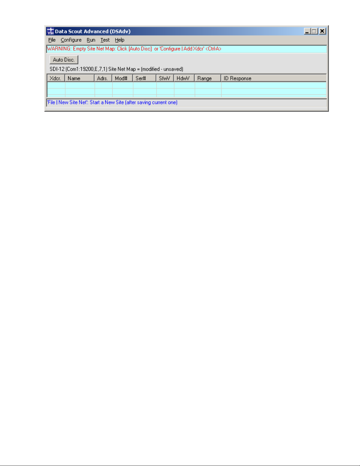
Figure 1.0
The main Data Scout Advanced window has a typical Windows
®
menu bar and status bar at the top and a single visual control (e.g., a
button). The middle of the window contains a spreadsheet-like table, also called the Site Net Map. It displays Level Scouts defined for
the current site network. Each displayed “row” of this table defines a single transducer and shows all the data obtained by configuring
and querying it. These data rows are listed under a header row with various labeled columns. There are also some “hidden” controls
or menus in the window, accessed by clicking the status bar, by clicking the Site Net description label, or by right clicking the Site Net
Map. Useful ToolTips may be obtained for most labels and controls by hovering the mouse over them. Finally, the bottom of the
window contains a special MenuTip status bar
.
The menu items on the main Data Scout Advanced window control all site-network specific or software specific configuration
functions, such as:
Configure a New site net, Save (or copy) the current site net to a default (or named) file, or Open a previously-
defined and named site net files.
Select transducers (individually or in random groups) for use by other major menu functions (such as Delete,
Query, Run and Test).
Add, Insert, Delete or Edit the rows for individual transducers (and their various parameters) on the current site net.
Query all, individual, or selected groups of transducers on the current site net. This simple function checks that
transducers are operable by reading (and displaying) their “basic” ID string data. A single button queries all
transducers at the same time.
Configure one-time setup operations for Data Scout Advanced such as: defining a suitable text editor for viewing all
Data Scout Advanced generated data files, defining where the Data Scout Advanced “online” operations manual is
located, or defining where Data Scout Advanced-generated files are archived for backup purposes.
The first (leftmost) column of the Site Net Map contains a relative transducer # (labeled Xdcr.) used as a notation for that row’s
transducer on various other windows and reports. This is followed by two other user-defined columns including: an optional
transducer name (up to 16 characters) and a required unique transducer address. Once a transducer is queried, various ID parameters
are read from it. These fill in other columns of the map with transducer model #, transducer serial #, and other internal ID
information. Thus, the Site Net Map shows all the defined (functioning or not) transducers that are currently defined on the selected
point-to-point connection (for a single transducer) or on the serial multi-drop network (for multiple transducers).
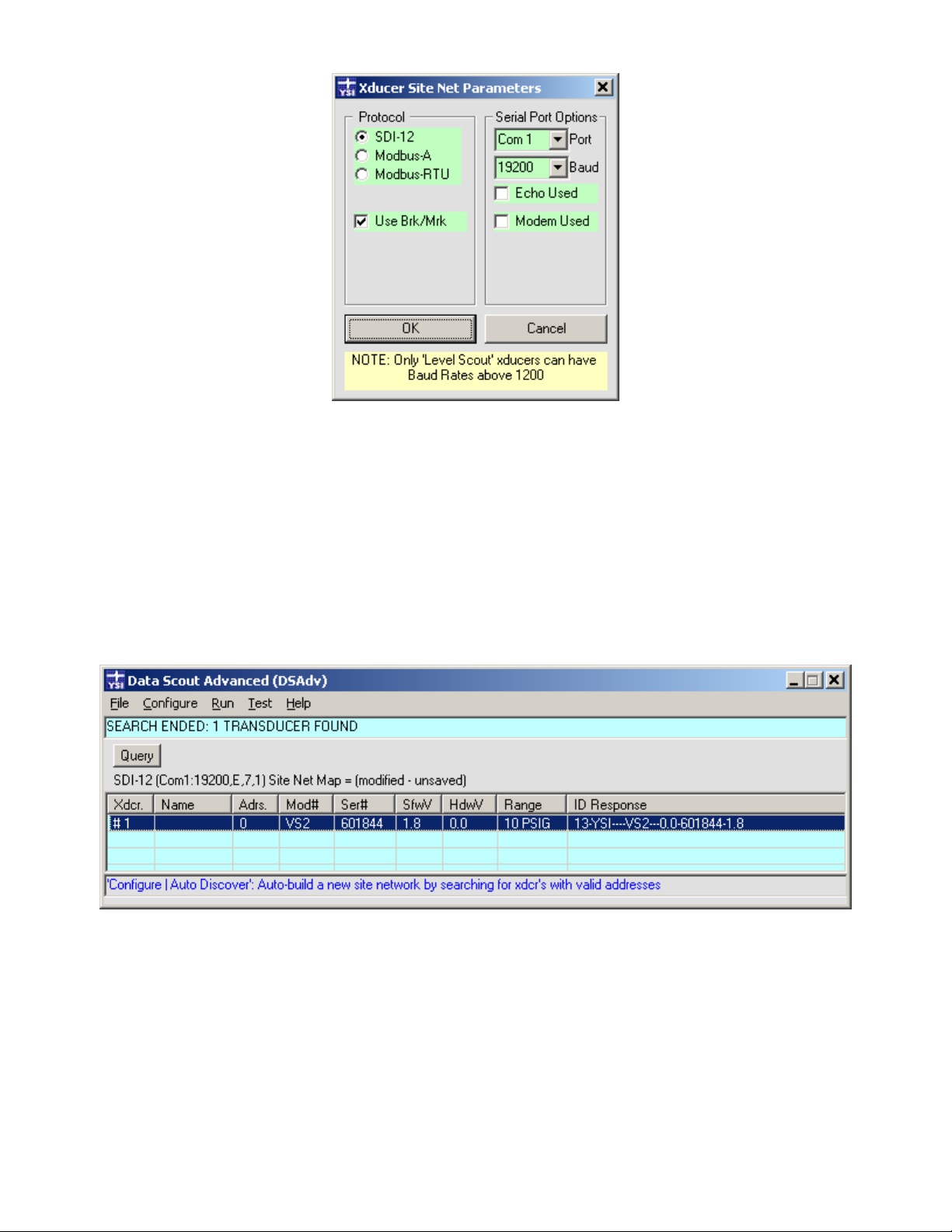
Other site-specific information (i.e., protocol, serial port #, serial setup parameters, site net file name, and the edited/saved status of the
originating .net file) is summarized on a label displayed just above the Site Net Map. Clicking this label (or selecting Xducer Site
Network from the Configure drop down menu) opens the dialog window shown in figure 1.1. This window shows the site network’s
protocol and serial port communication parameters. The default settings for all Level Scouts are SDI-12 protocol and 19200 baud.
Although the user may change the baud rate, the Level Scout will always communicate using SDI-12 protocol. If the user changes any
of these parameters the OK button is enabled to allow saving the changes.
YSI Incorporated Data Scout Advanced 2
Page 7
When exiting Data Scout Advanced, the current site’s definition (including ID information if already read from each transducer) is
automatically saved in a default site net file (DSAdv.net). This “latest” site net is restored automatically the next time Data Scout
Advanced is started. Menu sub-items on the File menu allow the user to create, save, and/or open other explicitly named site nets (.net
files). Select File | New Site Net to create a new site, select File | Save Site Net or File | Save Site Net As to save a new site or copy a site,
or select File | Open Site Net to open an existing site. When changing site networks, a prompt will appear allowing the user to save or
discard the current site network information.
When a site net has one or multiple transducers defined, any single individual transducer may be highlighted on the current Site Net
Map by left-clicking its row (figure 1.2).
Figure 1.1
Once a row is highlighted, its transducer has been selected to be acted upon by a subsequently performed menu function. Some menu
functions allow multiple transducers to be selected while others require that only a single transducer be selected.
Figure 1.2
By holding the <Ctrl> or <Shift> keys on the keyboard when left-clicking the mouse, the user can select multiple transducers on the
Site Net Map simultaneously.
Whether a particular menu item operates on one or multiple transducers is indicated by a descriptive item, in parentheses, at the end
of that menu item’s descriptions line. For example, (HiLi Xdcr) means it affects only one selected transducer, while (HiLi Xdcr(s))
means it affects all highlighted transducers. A special case (ONLY Xdcr) means that the function only works if ONE transducer is
defined on the Site Net Map (figure 1.3).
YSI Incorporated Data Scout Advanced 3
Page 8
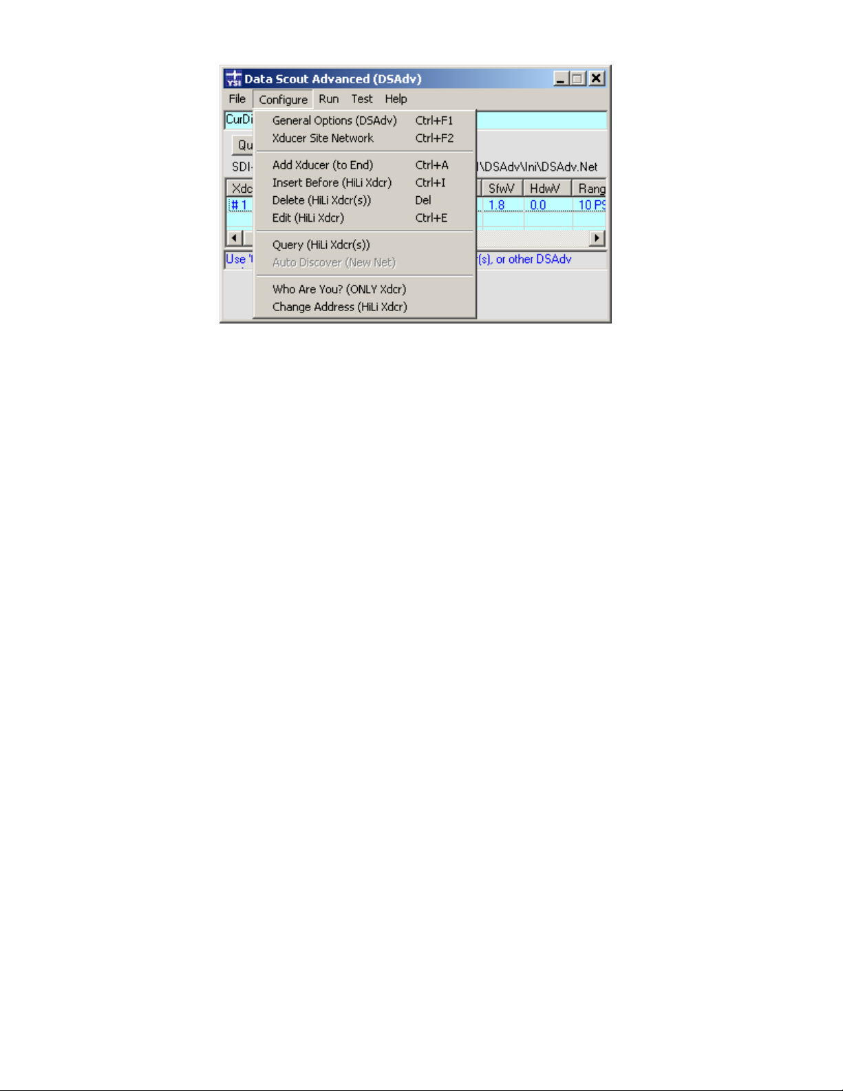
Figure 1.3
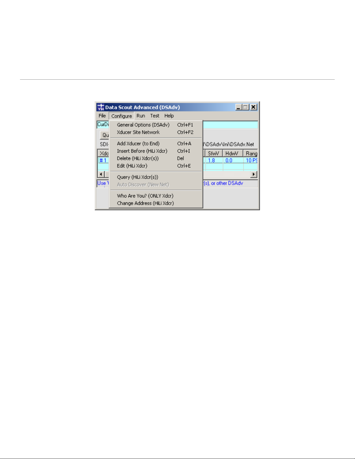
Functions are selected from the Configure drop down menu located in the main menu bar at the top of the window (figure 1.3), or
selected from a “hidden” Site Net Map context menu that will open when the user right-clicks over any row of the Site Net Map. This
context menu duplicates the most frequently-used site-network-editing, querying, and diagnostic functions available from the main
menu.
Also notice that many menu functions have alternate keyboard shortcuts for activating them (<Function Key>, <Ctrl>+<Key> or
<Shift>+<Key> or <Ctrl>+<Shift>+<Key>). These shortcuts, when available, are listed at the far right of the descriptions of each
menu item. Such keyboard shortcuts can be executed without displaying the menu.
Depending upon the defined column widths and amount of information displayed on each row of the Site Net Map, the user may need
to use a horizontal scroll bar to see all of it. Alternatively, the user can resize the width of the main Data Scout Advanced window by
dragging its left or right boundaries. The window’s height is automatically sized to show the number of transducer(s) defined in the
current Site Map. The window remembers its current size and position when Data Scout Advanced is closed and restores that last size
and position when restarted.
The various columns on the Site Net Map can be varied in width, by dragging (left or right) a special mouse icon (i.e., left and right
arrows pointing away from a single vertical line) that appears as the mouse hovers over the boundary between two column header
labels. The user can hide any unused columns by dragging it left to “zero” width. Once a column has been hidden, another special
mouse icon (i.e., left and right arrows pointing away from a double vertical line) appears as the mouse hovers near the column label
boundary. It allows the user to drag a hidden column (right) to a visible width again. Data Scout Advanced remembers the most
recent column widths used when it exits, or when a particular site network is saved. It restores these column widths when Data Scout
Advanced is restarted.
The File | Archive Files (DSAdv) menu item opens an Archive window when selected. This function is particularly useful when the
many files generated by Data Scout Advanced need to be moved or backed-up on other network or removable disk drives.
The File | View Files (DSAdv) menu item causes an Open File window to appear that shows all the files and subfolders of the Main
Base Path (“installation” folder) of Data Scout Advanced. These subfolders (Ini, Dat, Cmd-Log, Report, and Firmware) contain all the
initialization, data, scripts (commands and logs), report, and firmware hex image files used by or generated by Data Scout Advanced.
The Configure menu provides a large submenu of choices separated in four sections (figure 1.3). The first section contains items for
configuring the current site network’s serial port parameters, and other general options of Data Scout Advanced. The second section
has functions for editing rows of the Site Net Map, including an Add function for adding a new transducer to the end of the map and
the Insert, Delete, and Edit functions for editing selected (highlighted) row(s) of the map. The third section contains a Query function
for single (or multiple) selected transducer(s). However, if Site Net Map is empty (i.e., New), this section provides a useful AutoDiscover function in place of the Query function that can automatically build an entire network of transducer(s). The fourth section
contains diagnostic transducer configuration items useful in bringing a single new transducer (with possibly unknown address) onto
the current site network.
YSI Incorporated Data Scout Advanced 4
Page 9

The last menu bar item, labeled Help, provides a submenu leading to four help features of Data Scout Advanced. These provide quick
tips on using Data Scout Advanced features, access to the Data Scout Advance Operations Manual, access to the YSI web site, and show
the current version of Data Scout Advanced. In addition to this Help menu, do not forget the many ToolTips available. Similar
MenuTips appear in a status box at the bottom of the window. These display a summary description of the “last clicked” menu item’s
function. The Help | Tips menu also provides a descriptive panel summarizing the functions of all menus.
A single Query button below the menu bar allows the user to manually query the entire network which makes each transducer return
its ID String. This string, when received by Data Scout Advanced, is broken up into other useful fields that are also displayed on the
Site Net Map. This button is replaced by an Auto Disc. (auto-discovery) button, whenever the Site Net Map is empty. When the user
clicks the Auto Disc. button, it changes to a Stop button, which can be used to stop the Auto Discovery process once it discovers all the
expected transducers. The user must manually set the correct communications parameters (e.g., baud rate) before using auto
discovery. The default settings for all Level Scouts are SDI-12 protocol and 19200 baud. Although the user may change the baud rate,
the Level Scout will always communicate using SDI-12 protocol. If it fails to find any transducers, change to another baud rate and/or
com port and try again.
The Run window operates and/or configures individual transducers or the collection of all selected transducers. There are two
methods of activating this window. The first activates all operable transducers defined on the main Data Scout Advanced window.
The second activates any single (highlighted) transducer or for a group of selected (highlighted) transducers. In either case, once the
separate Run window is displayed, its selected transducers can begin to acquire “live” (real-time) data, display it, and optionally record
it to a data file (in various formats). All this is controlled from the Run window’s menu bar, or by using alternate visual controls
organized in several frames just below the window’s menu bar and status bar. See Chapters 3 and 4 for more information and
examples.
The Run window is used to display acquired “live” data or AutoLog data in various table (text) or graphic (plot) forms at the time
these data are acquired or extracted. Optionally, the user can also Record the acquired “live” data to disk the PC in one of two
selectable formats. A recorded .txt data file can be displayed later, offline, with a simple text editor. A recorded .csv (comma separated
variable) data file is also “readable” by a text editor, but is best viewed by a spreadsheet application which can further edit and process
(e.g., plot) the data in the file. Data extracted from a Level Scout are similarly written to data files in one or two formats (.atd and .csv)
where .atd stands for AutoLog Test Data and is the text version. These extracted data files can also be viewed and plotted by Data
Scout Advanced. All these recorded data files created by Data Scout Advanced can also be played back off-line, extensively edited, and
displayed in various ways via a Data Scout Playback application selected from the Data Scout Advanced menu on the Run window. It
is also available as a separate Windows
®
application, DSPlay.
Additionally, the separate Run window provides its own Configure menu functions that view and edit any of the internally stored
options and features of a selected transducer. These functions allow the user to view the current value/state of each transducer option
or change that option’s value/state. Some options require the user to “unlock” the transducer prior to changing it which will be
discussed later.
The user can also “broadcast” a particular option change to all the transducers currently assigned to the Run window.
The Data Scout Advanced main menu bar also has a Test function whose only submenu item is an Execute Script function for the
“more advanced” users. Using the Script function does require knowledge of low-level transducer commands. However, such
capability is rarely required to operate most transducer functions, which are provided by other built-in Data Scout Advanced “pointand-click” functionality.
2.0 INSTALLATION AND SETUP
2.1 INSTALLING DATA SCOUT ADVANCED
Before installing a new version of Data Scout Advanced, be sure that any older versions (in the same path) have been removed first.
The standard Windows
application program active. Thus, before installing Data Scout Advanced, ensure all other applications are closed. Failing to do this
may leave shared files active, causing confusing errors during installation.
Insert the information and support CD in the computer
Navigate to the CD drive
Double click on the DSAdvIns.exe file
YSI Incorporated Data Scout Advanced 5
®
installation program SETUP.EXE is used to install Data Scout Advanced. It insists that it be the only
Page 10

This will load the Windows
process.
After installation, Data Scout Advanced can be executed via the Windows
®
SETUP program, which guides the user through the remainder of the installation
®
Start menu by selecting Start | Programs |
Data Scout Advanced | DSAdv.
2.1.1 INSTALLING DATA SCOUT OPERATIONS MANUAL
The CD labeled Level Scout Information and Support contains the Data Scout Advanced Operations Manual as a .pdf. The file name is
DSAdv_605815C2.pdf
The user can access the .pdf file directly from the CD or via the Internet browser using the Index.htm file as an index. To avoid having
to insert the CD to access the manual, save this file to a hard disk folder on the PC or network. This can be accomplished by copying it
from the CD to the desired place. The recommended path is C:\YSI\DSAdv\Manual.
After saving the manual to the PC or network, Data Scout Advanced can be configured with the new manual location. To do this, use
the Configure | General Options (DSAdv) function on the main Data Scout Advanced window’s menu. On the configuration window,
double-click the text box labeled: Choose Path for Manuals. This pops-up a common dialog box that allows the user to navigate to
where the manual has been saved. Locate the file DSAdv_605815C2.pdf and click it so that its name (full path) appears in the File
name: box. Select the Open button to save it. Finally, select OK to save this full path name on the General Options window. The
Operations Manual is then directly available by selecting the Help | Manuals menu item.
2.2 CONFIGURING THE PC FOR A SERIAL NETWORK
The user must select a serial port available on the PC (COM1 ... COM16) to interface the computer with the Level Scout(s) at a
particular site on a serial point-to-point (or multi-drop) network. The YSI 771 adapter will allow the user to convert the native RS-485
signal of the Level Scout to RS-232 signal of a PC. If the PC does not have a serial interface, the user may add a USB type device (with
software driver). YSI offers the model 773 for converting RS-232 to USB. For remotely located transducers, using cell phone (or
other) types of modems, a Virtual Serial Port (VSP) may be required. The VSP is a software driver that simulates one of the COM
ports on the PC and provides a TCP/IP data path (via the Internet and 3G cell phone networks) to the remote serial port of the distant
modem. YSI has verified that the RealPort VSP from Digi works with the Digi Connect RG cell phone modem. The freeware VSP
from HWgroup has worked with the AirLink Raven cell phone modem but with limited functionality.
2.3 MANAGING/DISCOVERING TRANSDUCER ADDRESSES
A multi-drop serial network topography requires that all installed transducers use the same protocol and same baud rate. Also, each
transducer must have a unique address.
Such a network must be operated in a strict Master/Slave manner, in which the master controller (e.g., Data Scout Advanced software
operating on a PC) always plays the role of Master, and each of the transducers plays the role of a Slave. Only the Master can initiate
communications on the network. Slaves must never initiate communications on their own but must respond when requested to do so
by the Master. Generally, a transducer will only send a response out on the network after it receives a command from the Master that
explicitly contains its unique address. Also, a transducer must normally act “silently” even when it receives a command containing a
special address called the “broadcast” address (e.g., a command to synchronize data acquisition on multiple transducers).
There is one special transducer command (i.e., Who Are You?) that uses the broadcast address but violates the above rule. In response
to this “broadcast” command, a transducer responds with its address. However, such a command is meant only to be executed when
there is only one transducer wired physically to the network. Thus, if the user does not know the address of a particular transducer it is
not advisable to place it on the network until the address is known. In that case, only install the Level Scout with an unknown address
on the network and broadcast this special Who Are You? command to it. Once a transducer’s address is identified, add it to the larger
restored network (if its address is unique) or send it another command (Change Address): to change its address to a unique one before
connecting back to the network. The bottom section of the Configure menu on the Data Scout Advanced main window has both of
these infrequently-used “diagnostic” commands as does the bottom section of the right-click Context menu of the main window’s Site
Net Map.
The command Configure | Change Address (HiLi Xdcr) is a setup command that can be used to change the address of a transducer if
its address is already known. However, the window that appears when it is executed also has a “broadcast” check box option. This
option allows the user to also use this command (in conjunction with Who Are You?) if the “unknown” transducer is the only
transducer wired to the network and to set its address to some particular “known” address using the “broadcast” address to send it.
YSI Incorporated Data Scout Advanced 6
Page 11

This optional variation of the command refuses to execute if more than one transducer is currently defined on the Site Net Map. The
“normal address” variation works at anytime for any single highlighted transducer.
Two strategies for building a complete transducer site network, when faced with multiple transducers set to unknown addresses,
protocols, and baud rates, is to connect each one to the computer’s specified serial port, one at a time, and follow one of the
procedures below (labeled Methods 1 and 2). In each case begin with the Configure | Xducer Site Network command to set the
“starting” communications parameters (port, protocol, echo requirements, and baud rate) of the serial network connected to this
transducer.
Method 1:
Set the assumed communication parameters under Configure │Xdcuer Site Network. The Level Scout will always
utilize SDI-12 protocol. The default baud rate from the factory is 19200.
Clear the Site Net Map with the File | New Site Net command.
Connect one transducer to the selected com port and use the Configure | Add Xducer (to End) command to specify
one transducer with the address 0 (the default factory address, a good starting assumption).
Skip setting the long Name of transducer (leave it blank).
Use Query to verify that the transducer is really set to correct address and working at the current specified baud rate.
If this fails (times out), then try the Who Are You? command to discover its address, which will also automatically
add that address to Site Net Map’s entry row. Then, use Query again to verify the transducer is working. If not,
repeat all the steps above at different baud rates and/or Com ports.
Method 2:
Set the assumed communication parameters under Configure │Xdcuer Site Network. The Level Scout will ALWAYS
utilize SDI-12 protocol. The default baud rate from the factory is 19200.
Clear the Site Net Map with the File | New Site Net command.
Connect one transducer to the selected com port and click the Auto Discover button to start an automatic process
that steps through all the valid addresses of the selected protocol at the selected baud rate.
If a transducer responds correctly to any address, that transducer is automatically added to the Site Net Map. Once
this occurs (a new row appears on the map) select the Stop button to terminate the continuing auto-discovery
process.
Use Query to verify that the new transducer is working correctly.
If this fails (times out), repeat all the steps above at different baud rates.
Once you are successful in determining the correct address and baud rate of each transducer remove it from the network and label it.
Repeat the procedure for each of the other transducers, one at a time, insuring that each has (or is assigned) a unique address and
common baud rate.
Final Network Assembly:
Interconnect all the transducers together in a valid multi-drop network.
Clear the Site Net Map with the File | New Site Net command.
Connect the entire network to the selected com port and click the Auto Discover button to step through all the valid
addresses of the selected protocol at the selected baud rate.
YSI Incorporated Data Scout Advanced 7
Page 12

Each transducer should respond correctly to its address, after which it is automatically added to the Site Net Map.
Do not click the Stop button until the auto-discovery process has found each transducer and added its row to the
map.
Use Query button to verify that the new transducer is working correctly.
Be sure to use the File | Save Site Net As command to give the new working site network a unique name. This will
allow the user to Open it later.
If any one transducer fails (times out), the user will have to isolate it again and try one of the above methods to
correct the problem.
2.4 MAKING DATA SCOUT ADVANCED LEARN AND FORGET
After Data Scout Advanced has operated for a while on a particular host PC with a particular set of transducers, it tends to remember
the configurations of its various windows and functions, and even the way specific transducers are configured on the network. This is
useful, in that the user doesn’t have to remember to manually reconfigure it each time Data Scout Advanced is started.
These “memories” of Data Scout Advanced are kept as a series of small text files, most with the .ini or .net file extensions. Most such
files are located in subfolder Ini of the Main Base Path (i.e., Data Scout Advanced install path). These files may be viewed with the File
| View Files (DSAdv) menu function on the Data Scout Advanced main window. If for some reason these initialization files should
become corrupted, or you simply don’t like the way Data Scout Advanced has remembered your settings, you can easily erase its
memory by deleting all these .ini files. Erasing the file is best accomplished when Data Scout Advanced is not running. After deletion,
Data Scout Advanced starts over, doing things the way it did when first installed. If you have invested some time in developing site
network definition files (*.net) unique to your configuration these may also be selectively deleted as needed.
The following table indicates which specific files are created for which memory function. Refer to the table to only delete selected .ini
or .net files without losing the entire past configuration work. Modifying their contents with a text editor is not recommended.
File Name Purpose
Main Data Scout Memory: remembers Data Scout Advanced
DSAdv.ini
main window size, location, site net map column widths, and all
its persistent Configure menu parameters.
Default Data Scout Advanced Current Network Memory. It
DSAdv.net
or
<anyname>.net
remembers the last network loaded into Data Scout Advanced
main window. This network will be restored automatically when
Data Scout Advanced is restarted, unless the Open function
chooses another explicitly named .net file.
Run.ini
Remembers the size and position and all other persistent options
on auxiliary pop-up windows of the Run window.
2.5 RECONFIGURING TRANSDUCER OPTIONS WITH RUN WINDOW
The procedures described in this section are transducer options that can be changed with the Run window’s Configure menu. Such
option changes are described more fully (with pictures and examples) in Chapter 4.
2.5.1 CHANGING PRESSURE UNITS IN TRANSDUCER(S)
From the Data Scout Advanced main window, start the Run window by selecting Run | All Xducers’ from the menu. In the Run
window, select (highlight) one of the transducers by clicking its row # on the Site Net Map. Normally, transducer #1 will be selected by
default. Then select the Run window’s menu item Configure | Pressure Units (HiLi Xdcr). A window will appear showing the selected
pressure units. Select the desired units option button to change units and then select the OK button to execute the change only for the
highlighted transducer. Alternately, select the option All Xducers in the Apply To frame, and then select OK to make this same change
YSI Incorporated Data Scout Advanced 8
Page 13

to ALL the transducers assigned to the Run window. Click Cancel to only view the current unit selection or to close the window
without saving the changes.
2.5.2 CHANGING TEMPERATURE UNITS IN TRANSDUCER(S)
Use the same procedure detailed in the previous section, but select the Run window’s menu item Configure | Temperature Units (HiLi
Xdcr) instead. Temperature units will be displayed (for highlighted transducer). Click Cancel to close the window without saving
changes or select a different unit and click OK to save changes.
2.5.3 CHANGING OTHER OPTIONS IN TRANSDUCER(S)
Use the same procedure detailed in section 2.5.1, but select any of the other Run window’s menu items. If unfamiliar with the purpose
of any option, avoid changing it. The options in the second section of the sub-menu can only be changed if the highlighted Transducer
is unlocked first. An appropriate window appears showing the selected option. Select Cancel to dismiss this window after viewing its
current value without changing the option. Select OK to send the current or modified option value on the window to the selected
transducer or to ALL transducers. Some special Write Protected options may be viewed only but not modified by users (e.g., the Main
Cal. Coefficients).
2.6 MANAGING OTHER COMMON DATA SCOUT ADVANCED ACTIVITIES
Most Data Scout Advanced configuration activities are automatic, and remembered persistently in behind-the-scenes historical .ini
files. However, a few features must be manually configured (normally only once) after Data Scout Advanced is installed. Such
activities are discussed in this section. These configuration activities are only summarized here to bring them to your attention early.
Chapter 3 describes them more fully with pictures and examples.
2.6.1 CONFIGURING A FAVORITE TEXT EDITOR FOR REPORT VIEWING/PRINTING/ETC.
When any report or data file is generated by any Data Scout Advanced window, human-readable plain text files are generated. Data
Scout Advanced usually provides a File | View menu function on that window to allow the user to view the report file’s contents. By
default, Data Scout Advanced uses the Windows
®
text editor NotePad for this purpose and a copy of this application opens in a
window already containing the text of the file to be viewed. After viewing the file, the user may also print, rename, copy, move, or
delete the file using other menu functions of NotePad. Since NotePad is limited as to the size of files that it can view or edit, the more
flexible WordPad text editor may also be used. Data Scout Advanced can be reconfigured so that NotePad is replaced by any suitable
text editor program that is installed on the PC.
Configure the Data Scout Advanced default text editor by selecting Configure | General Options (DSAdv) from the Data Scout
Advanced main window menu. On the window that pops-up, enter the full path name of the desired text editor application in the top
text box labeled Choose Path for Report Viewer (a favorite Text Editor). To avoid typing in a full path name, double-click this text
box, and a common dialog box opens allowing the user to navigate to any drive where the desired text editor’s .exe file is located. Then
highlight its file name and select Open. The full path name of this program is then transferred to the text box on the configuration
window. Finally, select OK on this window to save the full path name.
2.6.2 CONFIGURING DATA SCOUT ADVANCED TO HAVE AN ARCHIVE BASE PATH
Data Scout Advanced has a menu item File | Archive (DSAdv) on its main menu. It opens a window that is used to perform various
file maintenance functions on the many internal data files that Data Scout Advanced manages behind the scenes. These files are
normally kept, by default, in a series of subfolders of the Main Base Path. Data Scout Advanced is most efficient when allowed to
access all its internal files from the default Main Base Path subfolders on the user’s local hard drive at “C:\YSI\DSAdv\xxxxx”, where
‘xxxxx’ stands for a particular subfolder name. For example, all script logs of Data Scout Advanced are normally kept in the Cmd-Log
subfolder (C:\YSI\DSAdv\Cmd-Log). All data files of the Run window are normally kept in the Dat subfolder (C:\YSI\DSAdv\Dat).
For archive or backup purposes a second set of subfolders (with the same ‘xxxxx’ names) may also be defined by specifying a different
Archive Base Path. This alternate path allows all or certain Data Scout Advanced files to be copied or moved to like-named subfolders
on another disk drive (possibly a Network drive). When such an alternate base path is defined, the Archive window is expanded to
permit Delete, Move, and Copy file operations to be performed between like-named subfolders of the Main Base Path and the Archive
Base Path. The Archive window’s file manipulation operations are restricted to only these two sets of like-named folders.
To configuring the Archive Base Path select Configure | General Options (DSAdv) from the main menu of Data Scout Advanced. On
the window that appears enter the full path name of the desired base path in the third text box labeled Choose Base Path for Archive
YSI Incorporated Data Scout Advanced 9
Page 14

Folders. To avoid typing in a full path name, double-click this text box, and a dialog window opens allowing the user to specify a
particular drive and folder path.
Finally, press OK on the configuration window to save the new path name. Please note that the user is specifying only the Base path of
the Archive subfolders. No particular subfolder or file name should be included in this path name, as these will be added later in the
proper context. Such Archive subfolders will also be created as needed by the Archive window.
For information on using the Archive window, see Chapter 3.
2.7 IN CASE OF DIFFICULTY
If you have any trouble getting Data Scout Advanced to run reliably on the PC, please review the following trouble shooting section.
2.7.1 PROBLEMS INSTALLING DATA SCOUT ADVANCED
When installing Data Scout Advanced, be sure that no other applications are active when the installation is attempted. Otherwise, it
may find some files (e.g., .DLL’s) active that it is trying to overwrite. Also, always uninstall any older version of Data Scout Advanced
(in the same path) before attempting to install a newer version.
®
Occasionally, Setup will indicate that the files are “out of date” and prompt the user to restart Windows
After restarting Windows
find “out-of-date” files, ensure you have the latest Windows
®
, the user may have to repeat the installation process. However, if after restarting Windows®, it continues to
®
Service Pack installed.
in order to solve the problem.
2.7.2 DATA SCOUT ADVANCED DOES NOT RECOGNIZE ONE OR MORE TRANSDUCERS
The most common problem communicating to transducers via serial interfaces using Data Scout Advanced is that all parties are not set
to use the same serial parameters. In particular, a common baud rate must be set in each transducer (and at the PC end), before the
parties can communicate. Data Scout Advanced has several special diagnostic commands for helping in these situations. Review the
detailed material in Sections 2.2 and 2.3 for more information.
2.7.3 DATA SCOUT ADVANCED WINDOWS DO NOT APPEAR WHEN STARTED
Most problems with Data Scout Advanced are due to corrupted files in the Ini subfolder that save the persistent options of Data Scout
Advanced windows when closed. By deleting all these files (usually with .ini or .net file name endings) and then restarting Data Scout
Advanced, most of these problems will disappear. Of course, any persistent options that track the normal usage will be gone, and must
be reconfigured.
2.7.4 DATA SCOUT ADVANCED INDICATES MULTIPLE COPIES RUNNING WHEN STARTED
The user can install multiple versions of Data Scout Advanced on the PC if each one is installed in its own unique path (e.g., install one
in C:\YSI\DSAdv, and another in C:\YSI\DSAdv2) when using Setup to install them. However, the user can only run multiple versions
if they have unique transducer communication port assignments and share no subfolders. During startup, Data Scout Advanced will
notice if its Site Net’s assigned Com port is already in use and warn the user that another copy is active. The user must then Exit the
second copy of Data Scout Advanced or change its Site Net com port to one not already in use.
3.0 CONFIGURING AND QUERYING A SITE
This chapter describes how Data Scout Advanced windows, tasks, features, and functions work. It focuses on the main Data Scout
Advanced window used to configure Data Scout Advanced and to configure and query a Level Scout transducer, individually or as
networks, located at one or more sites. Other major Data Scout Advanced functions (Run, Test, and Playback) are introduced briefly
here, but operate on their own separate windows. Detailed descriptions of these separate windows are deferred to Chapter 4
(Operating Transducers at a Site), Chapter 5 (Testing Transducers at a Site), and Chapter 6 (Processing Data Files)
YSI Incorporated Data Scout Advanced 10
Page 15
3.1 FREQUENTLY USED TERMS AND ABBREVIATIONS
The word transducer is abbreviated xducer (or xdcr) on all Data Scout Advanced windows, menus, and ToolTips.
The abbreviation <xdcr#>, or transducer number, is used to uniquely identify each transducer line (or row) on the Site Net Map of the
main Data Scout Advanced window and as a shorthand name for that transducer in certain reports and logs. It is not a characteristic
of the transducer itself. For example: #3 means the transducer that appears on the third row of the Site Net Map spreadsheet.
The abbreviation <xdcrid>, or transducer identifier, is a characteristic of every transducer itself, and is obtained from the transducer by
reading two values from its ID string: <model#> and <serial#>. These values are connected with a hyphen separating them. For
example: “AS2-019035”.
The abbreviation <yourxdcrname> is any 0 to 16-character descriptive name that is assigned to a transducer describing it (or its
physical site location) with the various “site net” editing functions. It is saved in Data Scout Advanced internal site net definition file(s)
and not in the transducer itself. For example: “Settle Tank 2”.
3.2 USE OF COLORS IN WINDOWS
Several background colors used in Data Scout Advanced have common meanings:
A light green color means that a control (text box, check box, radio control) contains data meant to be modified by
the user. A light pink color indicates modified. A white color indicates data for display only (i.e., the field cannot be
modified by the user).
Other bright colors (red, green, yellow) have conventional meanings like Stop (or Test Failed), Go (or Test
Successful), or Caution (or Test Successful but some measurement is out-of-tolerance or requires your attention).
Light (pale) versions of these colors usually decorate simple status boxes or spreadsheets.
The (foreground) color of a message’s text, when written to a status bar, also has meaning: black text for status or
general information, red text for error messages.
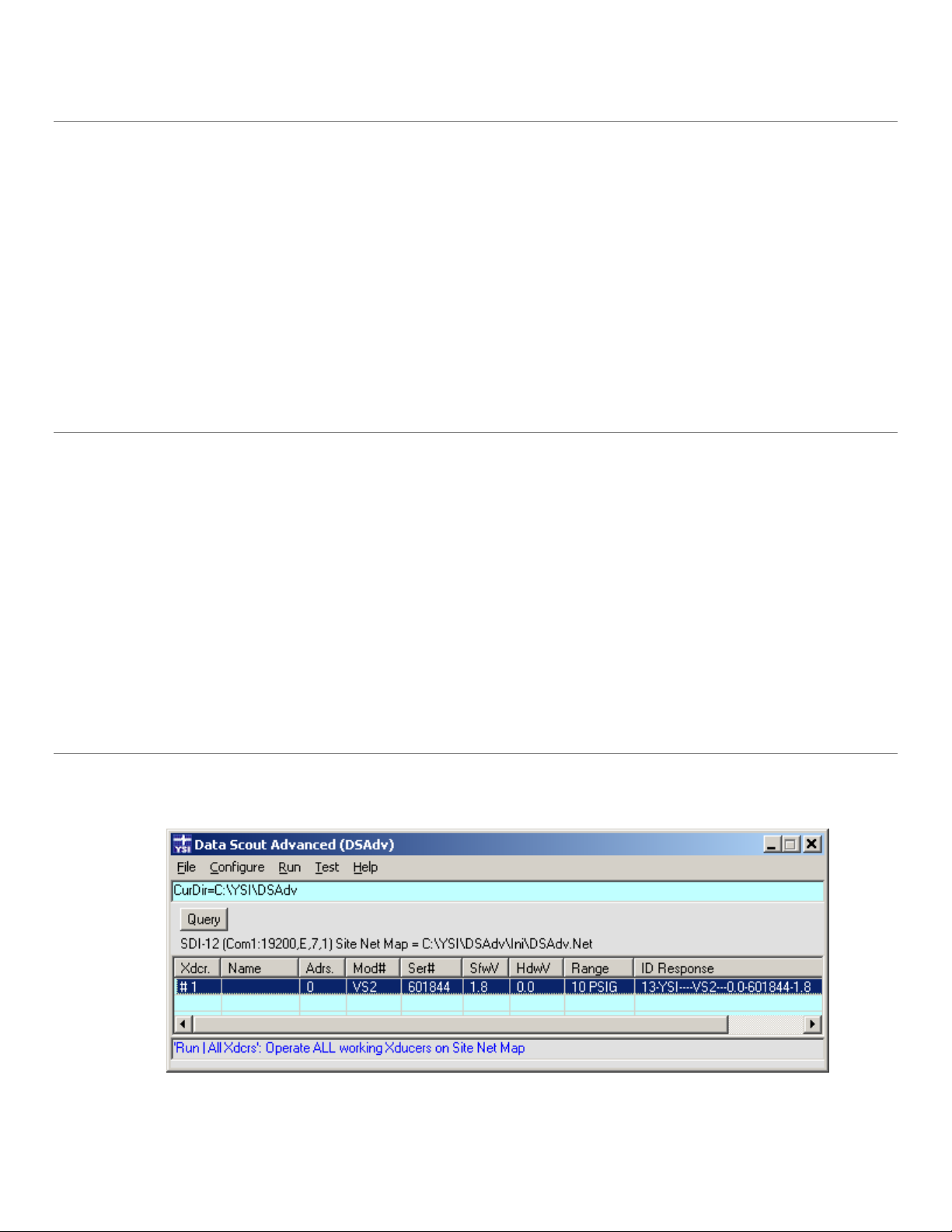
3.3 MAIN DATA SCOUT ADVANCED WINDOW AND SITE NET MAP
When Data Scout Advanced is started, it opens a single window. This window, titled Data Scout Advanced (DSAdv), is simply referred
to as the main Data Scout Advanced window throughout this manual (figure 3.1).
Figure 3.1
Starting at the top, it has a title bar, menu bar, and status bar. Below the status bar is a blank area containing a single button, normally
labeled Query, and a long label below the button describing the “current” site network of the transducer(s) selected. This long label
YSI Incorporated Data Scout Advanced 11
Page 16
gives the protocol, communication port setup parameters (in parentheses), and the full path name of a Site Net (.NET) file that defines
this collection of parameters. If the user has modified these parameters (and has not yet saved them) the path name is replaced by
(modified - unsaved). A MenuTips status bar at the bottom of the window shows the purpose of the last menu item selected whether
it was executed fully or not. It compensates for menus not having any ToolTips.
The middle of the window contains a spreadsheet-like table with labeled columns and numbered transducer rows. It is called the Site
Net Map and shows all the transducers connected to the current site’s network (in example above it is only a single transducer plugged
directly into the serial port of a PC). After the list of transducer(s), the table has one (or two) blank lines (i.e., a place to add another
transducer). All the defined transducer(s) need not exist (yet) on the physical network connected to the specified serial port. As a
minimum, the user must enter a valid unique address field (in Adrs. column) on each transducer row. The unique address may be any
ASCII digit (0-9) or any upper/lower-case letter (A-Z or a-z) with “*” reserved as the broadcast address. An optional 16-character
transducer name (in Name column) may be defined. A relative transducer number field (in Xdcr. column) appears automatically as a
sequential count of the defined transducers. It is used as a default shortcut name for that transducer (along with the optional longer
Name) on various other windows and reports.
The other fields (remaining columns) of the table can be obtained (later) by using the Query function which reads an ID string from
the transducer(s) and stores it in the last ID Response column. This highly encoded ID string is then broken into its logical
components, which then fills out most of the other columns.
A status bar appears just below the menu bar. It may show the status (black text) or error (red text) messages from time to time. Any
error messages are also accompanied by a “beep” or “bell” sound (if the PC has a sound card with speakers operating). The status bar
initially contains a Current Path (or Directory) text string, initially showing the hard disk path where Data Scout Advanced was
installed. This install path is also called the Main Base Path, since it contains several other subfolders (e.g., Ini, Dat, etc.) where Data
Scout Advanced keeps all its internal files.
The user may view these internal files by using the File | View Files (DSAdv) menu function (section 3.4.2) or by simply clicking the
status bar. Using the View function may change the Current Directory string displayed in the status bar from its initial Main Base Path
to other paths that the user may navigate. Other functions may restore the initial path. Also note that this function is not limited to
accessing just Data Scout Advanced related files, but has all the controls and separate context menu necessary to navigate anywhere on
the PC’s network or local drives.
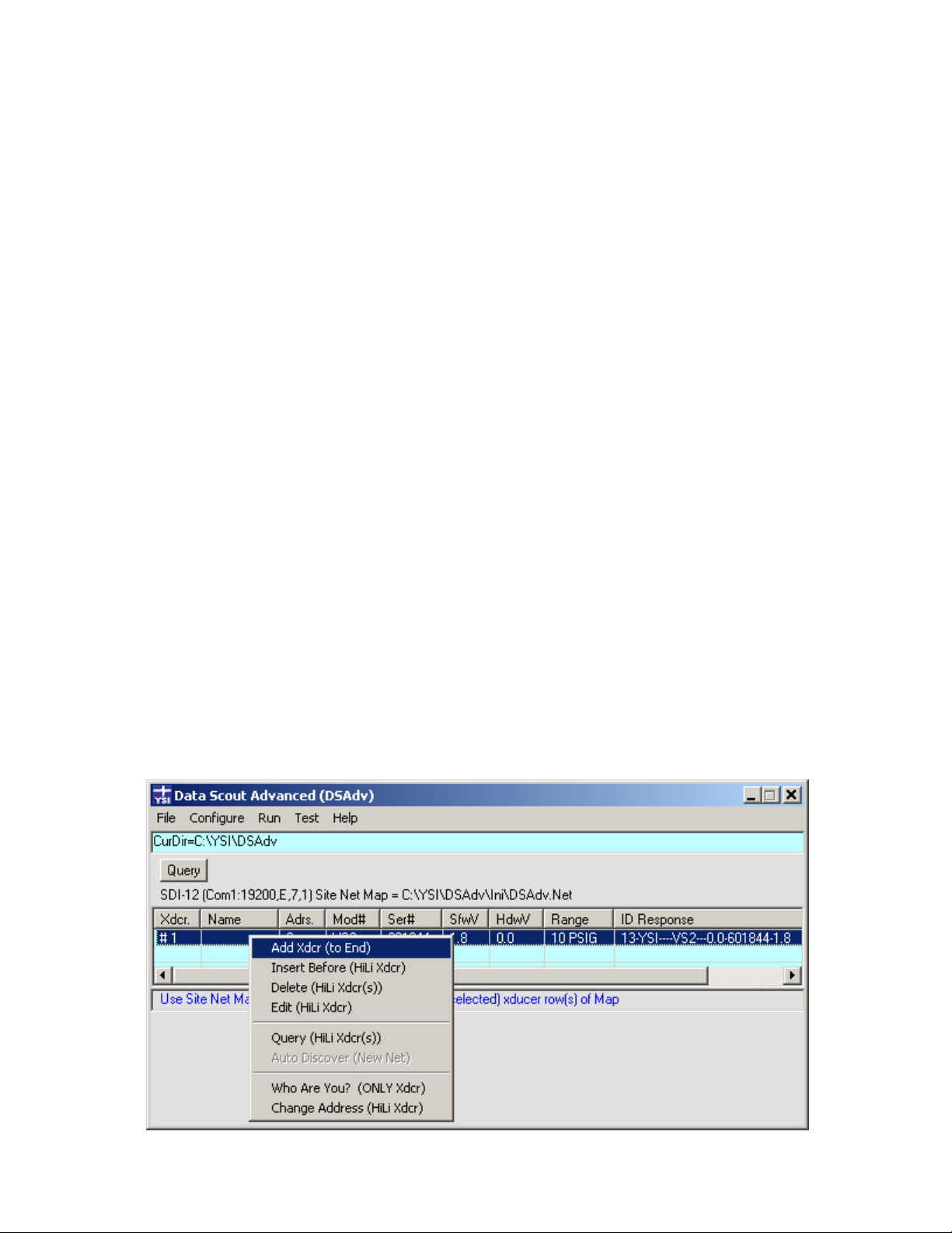
3.3.1 THE SITE NET MAP CONTEXT MENU
The Site Net Map has certain functions of its own that are easily accessed via a “hidden” menu called the Site Net Map Context Menu.
Most of its functions will address selected transducer(s) on the map. To Add a new transducer row to the end of the map, right-click
anywhere in map’s light blue data area to obtain the Context Menu. To perform an Insert, Edit, Who Are You?, and Change Address
function for a particular row, first select (highlight) that transducer row then right click on the row. To perform the Delete or Query
function, first select (highlight) single or multiple transducer row(s) then right click on the row. When the context menu opens it is
assigned to operate on the specified (highlighted) transducer row(s) (figure 3.2).
Figure 3.2
YSI Incorporated Data Scout Advanced 12
Page 17
The Query function in the context menu is the same “read ID string” function performed by the Query button for all defined
transducers on the site network but is performed only for the highlighted transducer(s). Other transducer/row editing functions are
also found in the first section of this context menu. Like the Query function, the Delete function may also be performed for more than
one highlighted transducer while the others can only be performed for a single highlighted transducer. These same transducer/rowspecific functions also appear starting in the second section of the main Configure menu (section 3.5.3).
Two special network diagnostic functions (Who Are You? and Change Address) are found in the last section of the context menu. The
first should ONLY be used when a single transducer is the only one physically connected to the network since it uses a special
“broadcast” address to “ask” the unknown transducer its address. See section 2.3 for more information on these two functions.
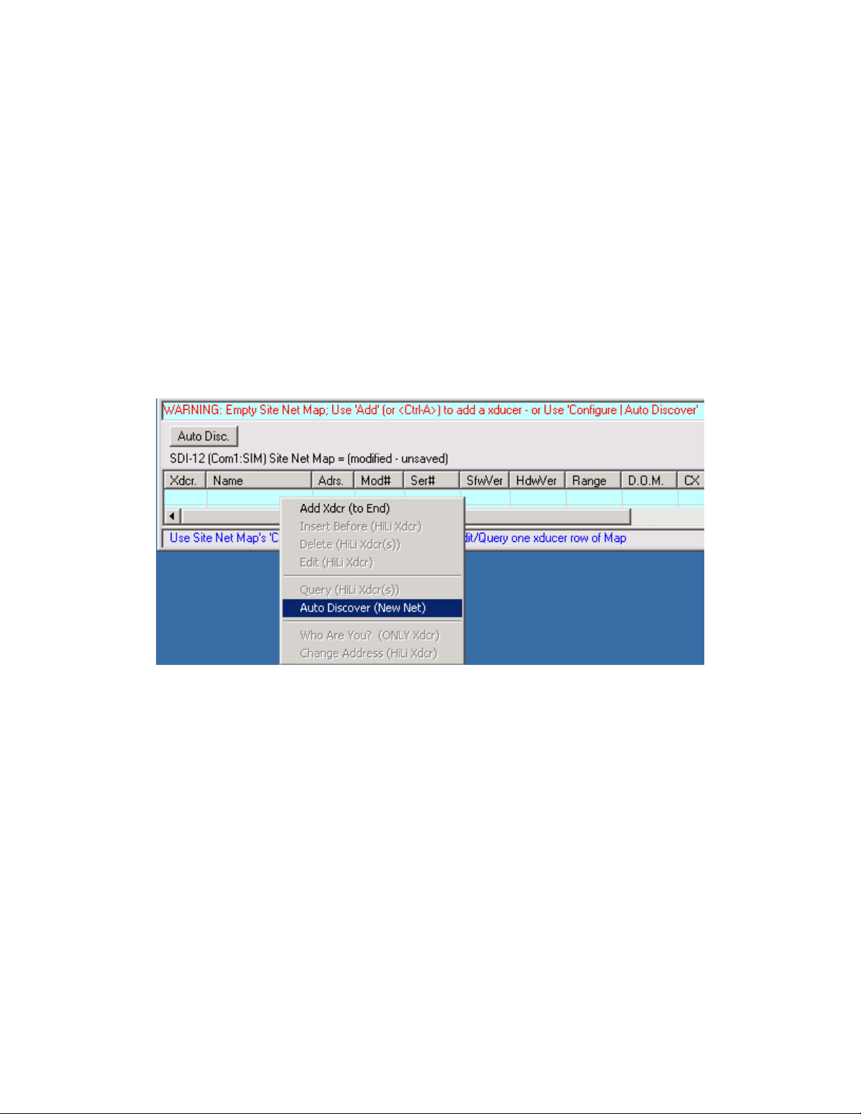
3.3.2 THE EMPTY SITE NET CONTEXT MENU AND AUTO DISCOVERY
Figure 3.3 below shows a variation of the context menu when the Site Net Map is empty (i.e., the last transducer was just deleted or the
File | New Site Net function was just executed). Not only is the Add function the only editing function available, but a new special
Auto Discover function is made available for use.
Figure 3.3
An Auto Disc. button replaces the Query button when the site net map is empty. However, it is necessary to first setup the Transducer
Site Net configuration per Section 3.5.1 before using Auto Discover. Then, if a suitable protocol and baud rate are set, clicking Auto
Disc. will cause Data Scout Advanced to automatically start querying each possible sequential transducer address. For each transducer
that responds, a new row for it will automatically be added to the map up to 16 transducers per Site Net Map. During the autodiscovery process, a Stop button appears that may be selected at any time to stop the discovery process.
YSI Incorporated Data Scout Advanced 13
Page 18
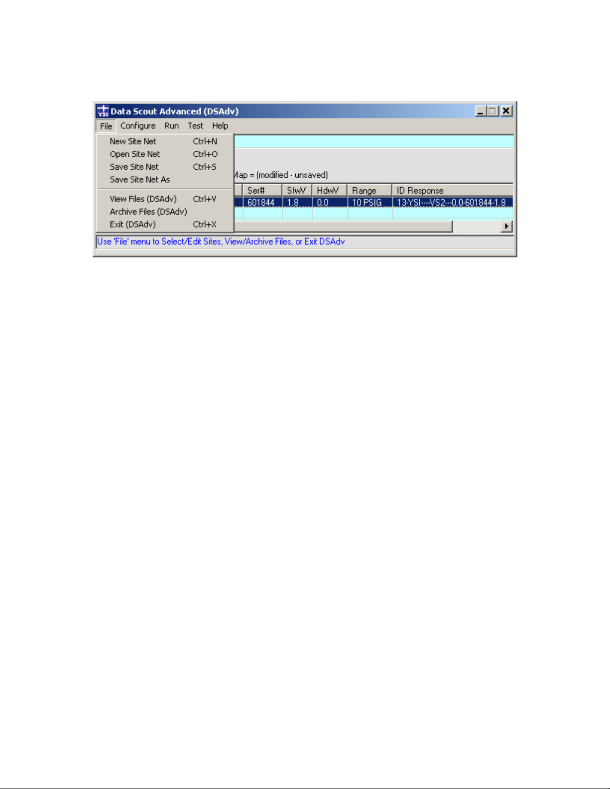
3.4 THE FILE MENU FUNCTIONS
The File menu selection, on the main menu bar, leads to a two-section submenu containing four “site network maintenance” functions
and three “overall” Data Scout Advanced functions (figure 3.4).
Figure 3.4
3.4.1 SITE NETWORK MAINTENANCE FUNCTIONS
The main purpose of the Site Net Map is to show information about each Level Scout defined on the current site network after
querying it. See section 3.3 for more information.
The File | New Site Net function causes the current site network to be erased. This clears the Site Net Map, and Data Scout Advanced
will not be very useful until at least one transducer is defined by using either the Add or Auto Discover functions. These functions may
be found on the Configure menu or on the Site Net Map context menu.
The File | Open Site Net function allows the user to choose any existing Site Network (.net) file previously defined and saved in the
Data Scout Advanced Ini subfolder. Selecting it opens an Open File dialog window. This dialog will show only available Site Network
(.net) files in the Data Scout Advanced Ini subfolder. The default file named DSAdv.net is the one always used to save the current site
net when Data Scout Advanced is closed. Open the desired file by selecting it and then clicking the Open button on that window.
The user may create uniquely named “site network” files by first using the File | New Site Net function, and then saving the finally
edited Site Net Map with the File | Save Site Net As function to give it a unique “site-descriptive” name.
The File | Save Site Net function causes the current contents of the Site Net Map to be saved to any named .net file (in the Data Scout
Advanced Ini subfolder) from which that current site net might have originated. If it simply originated from the default system file,
DSAdv.net, it is saved there instead.
The File | Save Site Net As function is similar to the previous function, but causes a Save As dialog window to open to allow the user to
name or rename the file which will save the current Site Net Map. Simply enter the new name in the File name: box, and click the Save
button. Thus, this function provides the ability to make new copies of existing site networks under different site-descriptive names.
Then, the user can open each file, and edit it uniquely for the particular site named.
3.4.2 OVERALL DATA SCOUT ADVANCED FUNTIONS
®
The File | View Files (DSAdv) function opens a Windows
Open dialog box, showing all the subfolders (and files) of the current path.
Its Look in: box permits the user to navigate anywhere on a hard disk, removable, or network drive. However, the dialog generally
starts in the Current Directory (normally the Main Base Path where Data Scout Advanced keeps its main working file subfolders).
Highlighting a file will make its name show up in the File name: box. Clicking the Open button will open that selected file as a text file
with NotePad, WordPad, or any text editor that Data Scout Advanced has been configured to use. Click the Cancel button to close the
dialog without viewing a file.
The File | Archive Files (DSAdv) function opens a special Archive window (figure 3.5). Its principal function is to provide an easy way
to view, delete, copy, or move any files in the Data Scout Advanced subfolders, and to back them up on an a alternate archive medium.
YSI Incorporated Data Scout Advanced 14
Page 19
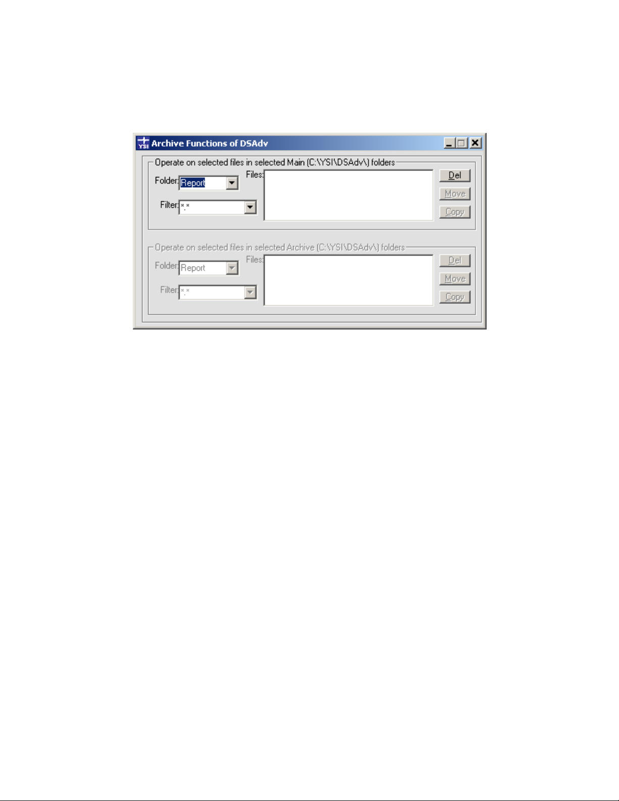
For new Data Scout Advanced installations, it is also used to copy files from an old installation. The archive window contains two
identical frames of controls. The first frame displays folders, filters, and their files from the Main Base Path (i.e., where Data Scout
Advanced is installed, and where Data Scout Advanced keeps its main data files in subfolders). The buttons in this frame allow the user
to Delete any of these files as well as Copy or Move selected groups of them to like-named subfolders of the Archive Base Path (i.e., a
separate location where these primary files can be saved for archive or back-up purposes). The second frame displays folders, filters,
and their files from the Archive Base Path (if one has been configured by Configure | General Options (DSAdv)). Its buttons allows the
user to delete any of these files as well as to copy or move selected groups of them to like-named subfolders of the Main Base Path.
Figure 3.5
Each of the frames operates exactly the same. Clicking the arrow at the right of the Folder: box will reveal the names of all subfolders
currently defined in its base path. Clicking the arrow at the right end of the Filter: box will reveal many useful “starter” filters that may
be used to limit the actual number of files that will appear in the Files: list box of the selected folder. However, the user may also click
the Filter: box after any filter is displayed there, and edit it. The Files: box will change immediately once the characters of the filter are
changed. If the Files: box is empty, then there are no files in the selected folder that match the filtering criteria. The three function
buttons in a frame act directly on all the files currently contained in the Files: box. Thus, clicking the Del button will Delete all those
files, and clicking the Move or Copy button will Move or Copy all those files to the other frame’s like-named subfolder.
The second frame is dim if a unique Archive Base Path has not been assigned in Data Scout Advanced using the Configure | General
Options (DSAdv) Main menu item. In that case the Archive window is only capable of deleting files in the Main Base Path subfolders.
Although the Archive window is highly restricted as to which folders it can copy or move files to, or to which it can delete files in, it has
some other very useful features:
The Files: Label (adjacent to the upper left side of the Files: box, either frame) has a ToolTip that always indicates the
number of files currently displayed inside its adjacent Files: box.
When a file name is displayed in a Files: box (either frame) and highlighted. At the same time the ToolTip for that
Files: box will be changed to include information about that highlighted file (i.e., it will show the full path, file name,
size, type of file, and date-last-modified). However, to see this updated ToolTip information, the mouse cursor must
be moved outside the box and then moved back into the box. Note that the current ToolTip only describes the
highlighted file, not just any file name entry in the box.
By double-clicking a highlighted file name in either Files: box, the Data Scout Advanced text editor will open in a
window to allow the user to view the contents of that file (if it is readable text, or in any format the text editor can
display).
Note that highlighting any file in a Files: box has no particular meaning, except for the last two items described
above. It does not in any way affect which files are copied, moved, or deleted. All the files in the box are affected
when Del, Move, or Copy action button are selected in the subject frame.
The File | Exit (DSAdv) function is used to close the Data Scout Advanced application. Exit terminates all concurrently running Data
Scout Advanced tasks and windows. If any files are open they are closed. Just before exit, the current site network is normally saved to
YSI Incorporated Data Scout Advanced 15
Page 20
the default file DSAdv.net. This file’s site net will be restored by default if Data Scout Advanced is restarted. In some cases, Data Scout
Advanced may refuse to exit until the user has manually ended some important task still in progress. In this case, a red text message
appears in the status bar.
Before exiting Data Scout Advanced, if changes have been made to the site net, the user may want to save it with an explicit name by
using the File | Save Site Net As function first.
3.5 THE CONFIGURE FUNCTIONS
The Configure Main menu function leads to an expanded submenu with four distinct functional sections (figure 3.6).
Figure 3.6
The top section has two items. General Options (DSAdv) configures several general working options of Data Scout Advanced. The
Xducer Site Network allows the user to view and edit all parameters of the current Transducer Site Network’s serial interface.
The other sections duplicate the exact same functions that also appear on the Site Net Map context menu which will be explained in
section 3.5.3.
The bottom section contains two special transducer network diagnostic functions that only apply to a single highlighted transducer.
These request or change the address of a selected transducer. The Who Are You? function only works if the selected transducer is the
only transducer on the physical network.
All these configuration functions are described fully, with examples, in the following sections.
YSI Incorporated Data Scout Advanced 16
Page 21
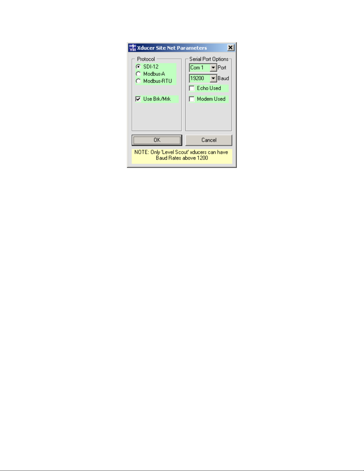
3.5.1 CONFIGURING THE TRANSDUCER SITE NETWORK
The Configure | Xducer Site Network menu function (or clicking the label that describes the site net parameters, just below the Query
button) opens the following window:
Figure 3.7
In this example one or more Level Scout transducers, utilizing SDI-12 protocol, are connected to communication port 1 at 19200
baud.
The Protocol should always be set to SDI-12.
The Use Brk/Mrk checkbox is normally checked. However, if a cell phone modem is used and the transducer’s Sleep Mode is disabled
(section 4.2.6), this option may be unchecked. This option was added because the Break/Mark timing sequences, that precede all SDI12 commands, do not get passed through VSP software (described below) and cell phone modems using the TCP/IP protocol. So,
disabling this option reduces the overhead of having to send these sequences. If you uncheck this option, you must remember to check
it again if you enable Sleep Mode again in the transducer (or Query will not work). When Sleep Mode is disabled battery consumption
will be greatly increased so the use of external power is required. This should not be a problem with a cell phone modem since the
same power source that energizes the modem itself can likely be used to also supply external excitation power to the transducer(s) on
that remote Site Network.
The PC may have several Com Ports as available choices. Any such port may be selected by clicking the arrow on the list box labeled
Port. If the computer comes originally without a serial port interface, the user must add a serial port interface card, install an external
USB serial port (and supporting driver, YSI part number 773), or install a “virtual” serial port (and VSP software), before any suitable
Port choices will appear in the Port list box. The list box is populated when Data Scout Advanced starts, so if a USB serial port was
plugged in while Data Scout Advanced was active, the user must exit Data Scout Advanced and restart it before that port can be
selected. A VSP is a software driver that provides access (using TCP/IP protocol) to a transducer connected remotely over the Internet
via a 3G cell phone modem.
Another similar list box, labeled Baud, also has several choices. The factory default of the Level Scout is 19200.
The setting of the Echo Used check box depends on the wiring of the network. If transmit and receive lines are tied together then any
transmitted character comes back on the receive line (i.e. echoes). RS-485 converter interfaces may block such echoes, though some
have a jumper option to pass echoes. If using the RS-485/RS-232 converter provided by YSI, leave this box unchecked. If unsure, try
it unchecked first. If the wrong option is selected, Data Scout Advanced will notify the user when the next Query command is issued.
YSI Incorporated Data Scout Advanced 17
Page 22

Leave the Modem Used check box unchecked if using a local hard-wired site network of one or more transducers connected to a
hardware serial port (e.g., COM1). However, if the Site Network is remote (connected via some transmission medium using one or
more modems), then check this box. When checked, two additional text boxes appear (figure 3.8).
Figure 3.8
The text box labeled Tel.No./IP/DNS identifies some address by which a remote modem can be located when Data Scout Advanced
starts. The type of address entered into this box depends on the type of modem(s) used and the transmission medium on the “other
side” of the COM port used (e.g., dial-up telephone line, radio, satellite, or wired TCP/IP link via a broadband internet provider):
If the Port list box has selected the local COM port of an analog “dial-up” modem (V92 type) installed on the PC,
then this box must contain all the digits of the Telephone Number that must be dialed to reach the remote analog
modem at the other end of the dial-up telephone line connection. The “*” character may be added anywhere in the
number sequence to introduce a delay (e.g., “9*1*757*865*7777”). This number is dialed by Data Scout Advanced
when it starts, or whenever this Xducer Site Net configuration window’s parameters are changed. Data Scout
Advanced will hang up the dial-up connection when it exits or just before it changes the Xducer Site Net window’s
parameters.
If the Port list box has selected a “virtual” serial port then this box should be left blank. Such a port is created by a
Port Re-Director or Virtual Serial Port (VSP) software driver installed on the PC. Throughout the rest of the
manual, the term VSP is used to refer to any such “simulated” port, and the VSP driver software must be separately
initialized before Data Scout Advanced starts. It must also be assigned a static IP Address and TCP Port # of the
remote cell phone modem (CDMA or GSM/GPRS type). In this case the transmission medium is the PC’s
broadband internet provider. Such a connection may be via a corporate LAN if fire walls are setup to permit such
TCP/IP communication. Some network providers also use a VPN (Virtual Private Network) connection to make the
modem’s static IP address operate securely.
YSI has evaluated two different VSPs. The first was tested with the AirLink ‘Raven’ modem (both GSM and CDMA
models). Be sure to disable all the NVT (RFC-2217) features of this VSP, since the AirLink does not support them.
The second VSP, called RealPort, was tested with the Digi Connect ‘Remote Gateway’ (RG) device (both CDMA
and GSM models exist, but YSI has only tested the CDMA model). RealPort is fully integrated with this device.
Both VSPs must be setup to simulate an unused COM port on the PC which must be selected from the Port list box
on the Xducer Site Net configuration window. If that port choice is not available, then the VSP driver was not
loaded and activated before Data Scout Advanced started.
Note
For some other types of remote modems the IP address or DNS name equivalent may be entered into this box
directly. Data Scout Advanced does not currently support such connections (possible future feature).
For local site networks (i.e., when Modem Used check box is unchecked) Data Scout Advanced uses a nominal timeout value of 2 or 3
seconds for transmitting and receiving all serial commands and responses. When a modem is used (box checked), commands and
responses take longer due to various latency problems in the communication medium (Internet, satellite, or radio link). A cell network
might have a typical ½ second latency when commands are being sent regularly. However, after a “silent” period (typically 20-30
seconds), with no commands sent, such a modem often enters a “sleep” state which requires a longer latency period of many seconds
to awake. In this case the XTime text box (figure 3.8) is used to specify this “worst-case” extra time period, in addition to the normal
timeout period. For cell phone networks YSI suggests using at least the 8 additional seconds (for a total timeout period of 11 seconds).
YSI Incorporated Data Scout Advanced 18
Page 23
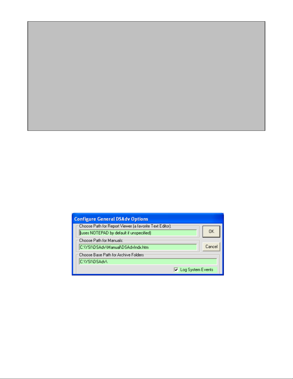
Note
YSI has tested two cell phone devices with the following results.
The AirLink Raven modems (GSM or CDMA) have remote serial ports (which connect to the remote Level Scout
transducer(s)) that can have their serial port communication parameters set only statically by sending manual AT
modem commands. The serial parameters do not get dynamically relayed to the remote serial port on the remote
modem when Data Scout Advanced sets them for its local “virtual” port. This limitation currently makes two Data
Scout Advanced features (on the Run windows Configure menu) inoperable via this modem: (1) the user cannot
change the baud rate of the remote transducer, and (2) the user cannot upgrade the firmware in the remote transducer
(since that requires a dynamic change of transducer baud rate and other communication parameters).
The Digi Connect “Remote Gateway” (RG) cell phone device (GSM or CDMA) has an integrated RealPort VSP. This
device and VSP combo can dynamically relay Data Scout Advanced’s local “virtual” serial port changes to the remote
serial port on the device. As a result, the user is able to: (1) change the baud rate of the remote transducer, (2) detect
modem signal changes on the remote RS232 port, and (3) upgrade the firmware in the remote transducer (although this
is not guaranteed 100% reliable and therefore, not recommended).
All configured transducers can be simulated by selecting zero (0) in the Baud list box. After setting 0 baud rate, each transducer
defined on that site network will no longer access the physical com-port assigned to it, but will operate in a simulation mode that
responds correctly to most transducer commands by returning simulated responses. Transducer internal configuration options,
changeable via the Run window (e.g., mode, pressure units, temperature units, etc.), are saved in a persistent memory file (<model#>-
<serial#>-XSimPer.ini in the Ini subfolder) for each simulated transducer. This simulation feature can be useful in debugging new
Script files before committing them to execute on real transducers. Simply restore the correct non-zero baud rate to make all
simulated transducers “real” again. The site network label is displayed in magenta when simulated transducers are in use.
3.5.2 CONFIGURING GENERAL OPTIONS OF DATA SCOUT ADVANCED
The Configure | General Options (DSAdv) menu function specifies general options of Data Scout Advanced (figure 3.9).
Figure 3.9
YSI Incorporated Data Scout Advanced 19
Page 24

There are only four General Options in this selection. All these persistent options are remembered in the DSAdv.ini file when saved
(i.e. when Data Scout Advanced is closed). The first three options many be entered by clicking its text box and typing in a full path
name (including a file name for the first two options, but not the last). However, to avoid typing such long strings, double-click each
text box to open a dialog window that allows the user to navigate to the disk drive to locate the desired path. The fourth option is a
simple check box that enables or disables writing of the System Log file. Click Cancel instead of OK to exit the window without saving
any changes made.
The first option specifies a favorite text editor to be used by Data Scout Advanced whenever the user needs to view any plain text
(report or data) files created by Data Scout Advanced. The default program is NotePad if this field is unspecified (blank). To use an
alternate text editor, enter the full path and file name of its .exe file. See section 2.6.1 for more details.
The second option specifies where the Data Scout Advanced Operations Manual is installed. In the example above, the user has
installed the manual in the Manual subfolder of DSAdv. However, it could have been installed on a shared network drive. See section
2.1.1 for more details.
The third option specifies the Archive Base Path, where Data Scout Advanced will copy or move (for backup purposes) any of its
primary internal data and initialization files in subfolders of the Main Base Path. In this case, the user is specifying only a drive and
base path (no file name is specified). The final path shown in the option field must end with a backslash (\), which is normally added
automatically. See section 2.6.2 for more detail on selecting an Archive Base Path. See File | Archive Files (DSAdv) function in section
3.4.2 for using the selected Archive Base Path.
The fourth option enables or disable the writing of a System Log file that records every major event that Data Scout Advanced
generates (while the file is enabled). A new file (named SYS_<date>_<time>.log) is created and opened in the Cmd-log subfolder each
time this check box is checked. The file is closed either when the check box is unchecked, or when Data Scout Advanced is closed. If
Data Scout Advanced is closed with this option enabled, a new System Log file will be automatically created and opened when Data
Scout Advanced is restarted.
Whenever the System Log file is open, Data Scout Advanced checkpoints (closes, then reopens for “append”) this file, each time a
diagnostic event is written to it. This allows you to open and examine this file while Data Scout Advanced is running if you have a
good text editor (like EditPadPro) that can open the file for read while it is still open for writing by Data Scout Advanced. A simple
text editor like NotePad may not permit this, requiring you to close the file manually (using ‘Configure | General Options (DSAdv)’),
or exit Data Scout Advanced, before examining its contents. The following example listing shows the format of this file:
--- System 'Diagnostic' Log File: (All Xducers)
--- Using: DSAdv Version: 1.7.0
--- Updated: 02-07-2008 at 16:08:45
000000.000005 : 000.000005 Open Sys.Log File C:\YSI\DSAdv\Cmd-Log\SYS_2008-02-07_16-08-45.log
000000.002254 : 000.002249 Start DSAdv Main Form
000000.004273 : 000.002018 Starting Command Line:
000000.016889 : 000.012617 Com Ports found: [ COM1=Site COM3=Avail. ]
000000.102848 : 000.085959 timBlink = 0
000000.105482 : 000.002634 Standby: Opening Com Port 1... with Settings 19200,E,7,1 In CommXdcr
000001.120208 : 001.014725 timBlink = 1
000002.119484 : 000.999276 timBlink = 2
000002.329100 : 000.209617 Row 1 Clicked
000003.126235 : 000.797135 timBlink = 3
000004.049048 : 000.922813 !!Start Run Form
000004.207101 : 000.158053 timBlink = 4
000004.227164 : 000.020063 Show_Status (Run): STANDBY: Reading Data From Transducers
000004.231221 : 000.004057 !!Show_Splash_Msg: STANDBY: Getting Xducer Data >>> Reading Lock State && Oper.Mode of
Xducer #1.
000004.253212 : 000.021991 TCmd+Bk+Mk= [0U]
000004.367305 : 000.114093 TRsp= [0+1 ] bk=0.012013 mk=0.008064
000004.487095 : 000.119790 !!Show_Splash_Msg: STANDBY: Getting Xducer Data >>> Reading Pressure Units of Xducer #1.
000004.498853 : 000.011758 TCmd+Bk+Mk= [0XUP]
000004.609940 : 000.111086 TRsp= [00032 ] bk=0.012006 mk=0.008001
YSI Incorporated Data Scout Advanced 20
Page 25

000004.614749 : 000.004809 TCmd(SRPoll)=[0]
000004.621342 : 000.006593 TRsp= [0 ] Rcv.Service Request (leftover)
000004.623733 : 000.002391 TCmd+Bk+Mk= [0D0]
000004.733513 : 000.109780 TRsp= [0+9+6 ] bk=0.012011 mk=0.008
000004.738575 : 000.005062 TCmd+Bk+Mk= [0M3]
000004.848199 : 000.109624 TRsp= [00033 ] bk=0.012001 mk=0.008006
000004.853304 : 000.005105 TCmd(SRPoll)=[0]
000004.860490 : 000.007186 TRsp= [0 ] Rcv.Service Request (alone)
000004.862843 : 000.002353 TCmd+Bk+Mk= [0D0]
000004.972907 : 000.110064 TRsp= [0-2.307300+0.000000-14.24048 ] bk=0.012031 mk=0.008001
000005.091869 : 000.118962 !!Show_Splash_Msg: STANDBY: Getting Xducer Data >>> Reading Temperature Units of Xducer #1.
000005.102893 : 000.011024 TCmd+Bk+Mk= [0XUT]
000005.213892 : 000.110999 TRsp= [00031 ] bk=0.012004 mk=0.008006
000005.219357 : 000.005465 TCmd(SRPoll)=[0]
000005.226470 : 000.007113 TRsp= [0 ] Rcv.Service Request (leftover)
000005.229060 : 000.002590 TCmd+Bk+Mk= [0D0]
000005.236519 : 000.007459 timBlink = 5
000005.339145 : 000.102626 TRsp= [0+0 ] bk=0.012003 mk=0.008002
000005.454689 : 000.115545 Show_Status (Run): READY: Use 'Acquire' menu or buttons (below) to start acquiring 'live' data
000006.228323 : 000.773633 timBlink = 6
: : : : :
001320.294216 : 002.689690 !!Show_Splash_Msg: STANDBY: Getting Xdcr. Data >>> Reading Current User-Units Offset/Slope Now!
001320.319388 : 000.025172 TCmd+Bk+Mk= [0I]
001320.437787 : 000.118399 TRsp= [013-YSI----BS2---0.0-607541-2.2 ] bk=0.012004 mk=0.008102
001320.448201 : 000.010414 {ExeXducerCmd} !!Xdcr #1 checked for HOT-SWAP but found none! Overhead = 0.125000 sec.
001320.453047 : 000.004845 TCmd+Bk+Mk= [0M3]
001320.567116 : 000.114069 TRsp= [00033 ] bk=0.012005 mk=0.008005
001320.573787 : 000.006671 TCmd(SRPoll)=[0]
001320.584190 : 000.010404 TRsp= [0 ] Rcv.Service Request (alone)
001320.587453 : 000.003263 TCmd+Bk+Mk= [0D0]
001320.699844 : 000.112391 TRsp= [0+2.307300+0.000000-14.24048 ] bk=0.012006 mk=0.008016
003645.904238 : 2325.204394 Unloading Run Form
003645.942010 : 000.037772 Standby: Closing Com Port 1...
003646.156356 : 000.214347 CommXdcr closed!
003646.165757 : 000.009401 Unloading DSAdv Main Form
The above example of a System Log file format is described below. After the first three initial header lines, all other lines are event lines
or blank lines. Some superfluous event lines have been removed for simplicity and replaced by a line of colons (: : :)
• The leftmost column of an event line is a time stamp. It show relative time (in seconds) that was accumulated since the file
was opened – when that event line was written. Actual time can be determined by adding this to the real-time data and time
stamp in the header.
• The second column is a delta time (in seconds) which is the elapsed time since the previous event was written to the file.
(value is meaningless for the 1
st
event line).
• The third column is a variable-length text descriptor string describing that particular diagnostic event. In cases where it is
very long, it may be shown folded onto a second or third line (without a preceding time stamp).
A blank line indicates the passage of time – and precedes any event line whose delta time is longer than 0.1 second since the previous
event line was written. In other words, any blank line indicates that at least 0.1 second (or longer) has passed without an event being
written to the file.
These event lines will be most beneficial to YSI Technical Support if you are experiencing a problem with Data Scout Advanced. You
may be asked by Technical Support to enable this setting in order to record any failure or problem you are experiencing. However,
some failures such as Visual Basic Run-Time Errors may not be detected by Data Scout Advanced. In such cases, you may need to tell
the YSI Technical Support Representative what key stroke you last entered at the time of the failure.
3.5.3 CONFIGURING TRANSDUCERS/ROWS OF THE SITE NET MAP
The second section of the Configure submenu (and the top section of a highlighted transducer’s Site Net Map context menu) contains
“editing” functions that operate directly on the rows (individual transducers) of the Site Net Map. Most of these functions will open
an additional window to gather needed information or to confirm execution.
YSI Incorporated Data Scout Advanced 21
Page 26
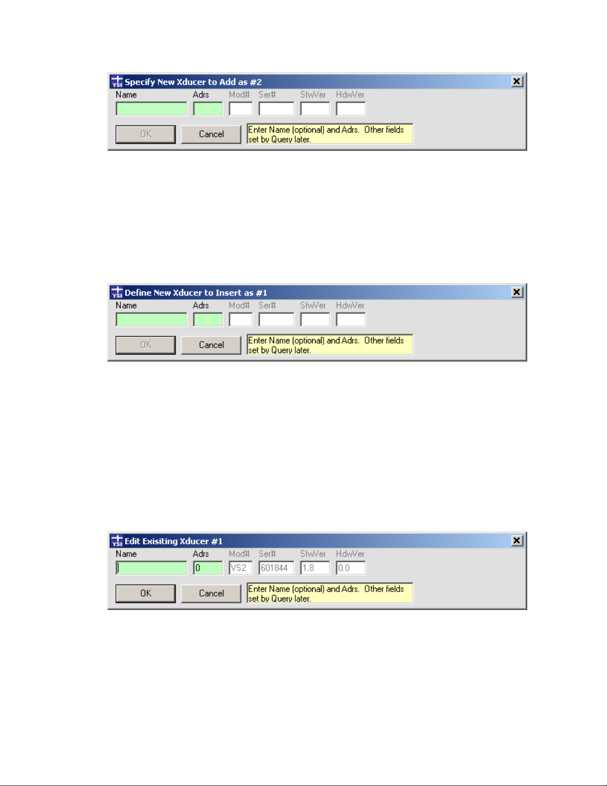
The Add function is used to add a new row to the end of the current Site Net Map. In figure 3.10, the title bar of the window indicates
that Transducer #1 was previously the last item on the map, and that this function, if completed, will add a new Transducer #2 to the
end of the map.
The Add function’s window has two fields where entries are possible for the transducer (i.e., the light-green fields). A descriptive
Name may be left blank, but a valid Address is required before the OK button will be enabled to allow the user to save the information.
The other white fields are read-only and used to display ID information that will be retrieved from the transducer when it is queried.
The Insert function is used to insert a new row on the current Site Net Map between the currently highlighted row and the row above
it. In figure 3.11, the title bar of the pop-up window indicates that Transducer #1 was the previously highlighted row on the map, and
that this function, if completed, will add a new Transducer #1 ahead of it on the map, thus renumbering the originally highlighted
transducer and pushing it down to be Transducer #2.
Figure 3.10
The Insert function’s window allows Name and Address fields be entered for the transducer (the light-green fields). The Name may be
left blank, but a valid Address is required before the OK button will be enabled to allow the user to save the information.
The Delete function is used to delete any existing highlighted transducer row(s) on the Site Net Map. The PC keyboard’s Delete key
may be used as a shortcut to invoke this function. The function opens a warning dialog window to be sure the user wants to delete the
transducer(s). It will not operate unless one or more existing rows on the Site Net Map, to be deleted, are highlighted first.
Figure 3.11
The Edit function is used to edit any or all of the individual fields (columns) of any existing highlighted transducer row on the Site Net
Map. In figure 3.12, the title bar of the window indicates that Transducer #1 was the previously highlighted row on the map, and that
this function, if completed, can selectively change any data fields belonging to Transducer #1.
The Edit function’s window initially shows the current data previously defined for every field of that transducer row. Any of these
fields (in light-green text boxes) may be changed as needed. Other fields (in white text boxes) can be viewed but not modified since
they are supplied by the Query function. Press OK to finalize any changes made, or press Cancel to ignore the changes made.
Other transducer configuration option functions, that actually change data inside a physical transducer, are found on a separate
Configure menu of the separate Run window. These are described briefly in Section 3.6 and described fully in Chapter 4.
Figure 3.12
YSI Incorporated Data Scout Advanced 22
Page 27
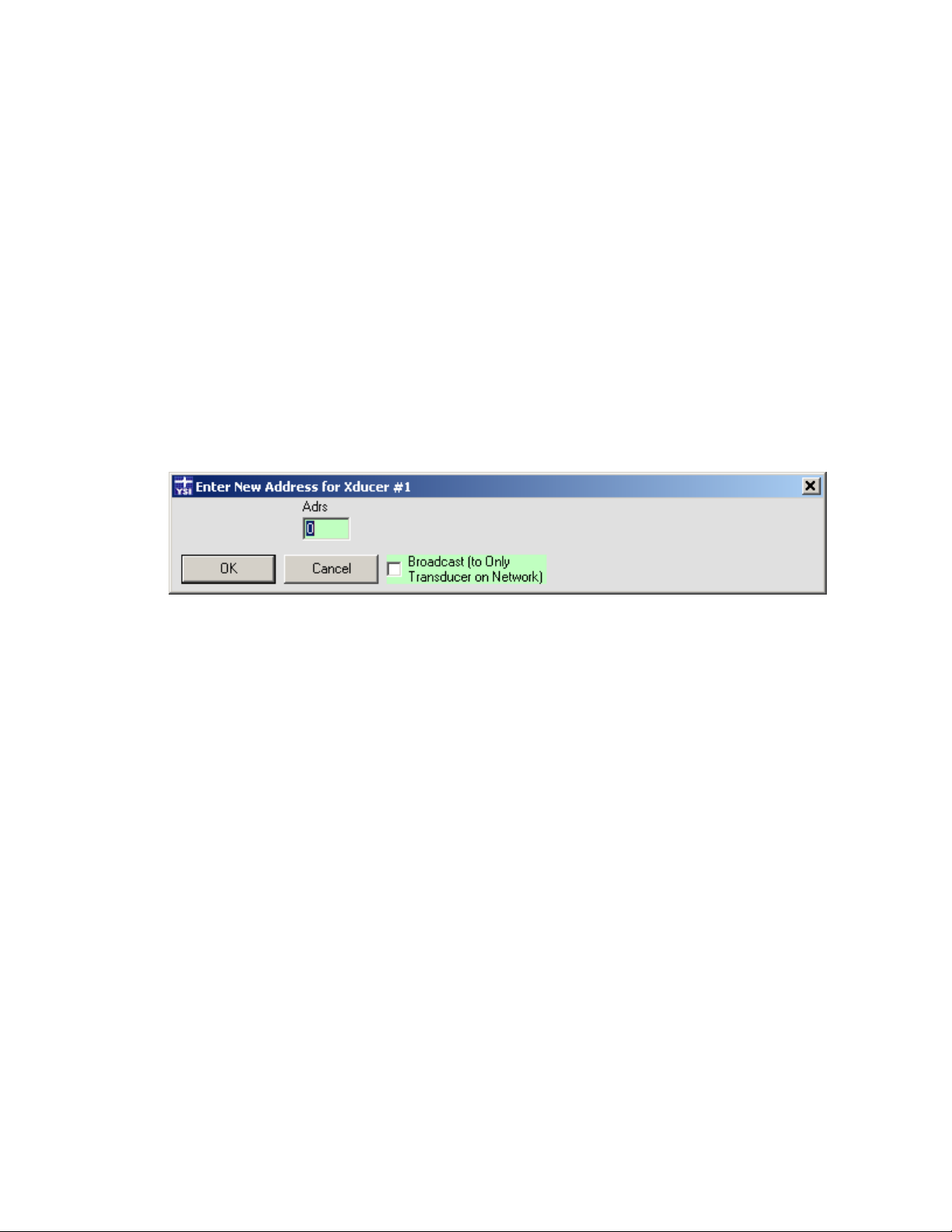
3.5.4 CONFIGURING OTHER OPTIONS OF THE HIGHLIGHTED TRANSDUCER
The bottom section of the Configure submenu has two transducer network maintenance items.
The first function called Configure | Who Are You? (Only Xdcr) will request that the only transducer on the network report its
unknown address. This is accomplished by transmitting a special broadcast command (i.e., one without a specific address). The
function is meaningless if more than one transducer is currently physically attached to the network since all transducers will respond to
the broadcast command simultaneously. The function is provided only to allow the user to identify a transducer whose address is
really unknown (assuming the baud rate is known).
The best way to avoid having to use this function is to reserve the default factory-set address of any transducer (0), and to only allow
non-default addresses to remain on the network. That way, when receiving a new factory transducer, the user can add it to the
network with its default (but unduplicated) address. Other methods for configuring networks from scratch are described in Section
2.3.
Change an address to any non-default (unduplicated) address, using the second function called Configure | Change Address (HiLi
Xdcr) which opens a new window (figure 3.13). Only the Address text box is available for entering data and a new check box option
(normally unchecked) is displayed. Click the check box option only if using it when there is only one transducer physically connected
to the serial port.
Figure 3.13
YSI Incorporated Data Scout Advanced 23
Page 28
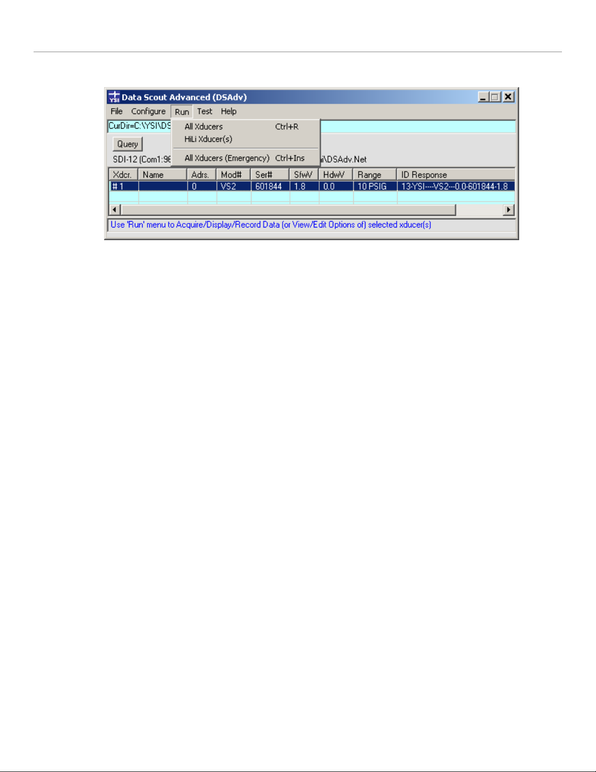
3.6 THE RUN FUNCTION
The Run menu has three functions (figure 3.14).
Figure 3.14
All items will take the user to the Run window which provides a data acquisition and recording function of Data Scout Advanced as a
single-cycle (on demand), periodic, or continuous data acquisition from all (or selected) transducers on the Site Net Map. The
window has many transducer configuration functions that read (and optionally set) various options inside individual transducers
currently defined on the map. Normally, modifications are limited to the currently selected transducer but may be “broadcast” to all
the transducers assigned to the Run function.
The first two sub-menu items are identical if there is only one transducer defined on the Site Net Map. However, if there are multiple
transducers defined and working (i.e., their Query functions have successfully filled in the necessary additional information columns
for their rows), the functions act differently. The first item will assign all working transducers on the map to the Run function and
start it. The second item will assign one or more highlighted transducer(s) to the Run function and start it. The bottom menu item is
used only in an emergency when one or more transducers does not respond to Query and the user needs to enter the Run window to
access certain transducer functions on the Run window’s Configure menu. See Chapter 4 for more information.
Once the appropriate selection is made, a separate Run window will open. This window initially starts with its own menu bar and
control buttons disabled, and with a STANDBY: message prominently displayed on its status bar. During this short period, the
function is reading certain necessary information from all the transducers selected for it. Various status windows may appear
indicating this. Once that information is obtained, its menu bar and control buttons will be enabled and many functions of the main
Data Scout Advanced window become disabled. This is to prevent transducer network changes while live transducers are operating via
the Run function. For pictorial examples and more information on using the Run function, see Chapter 4.
Also selectable from the separate File menu of the Run window is the Playback function which is actually a separate application
(DSPlay.exe). This function can read and display (as a text “spreadsheet” or graphic “plots”) any data file created by the Data Scout
Advanced Run window. This includes .txt or .csv ‘Record’ data files acquired “live” from any transducer or group of transducers or the
.atd or .csv ‘AutoLog’ files extracted from the transducers. For a complete description of this application see Chapter 6.
YSI Incorporated Data Scout Advanced 24
Page 29
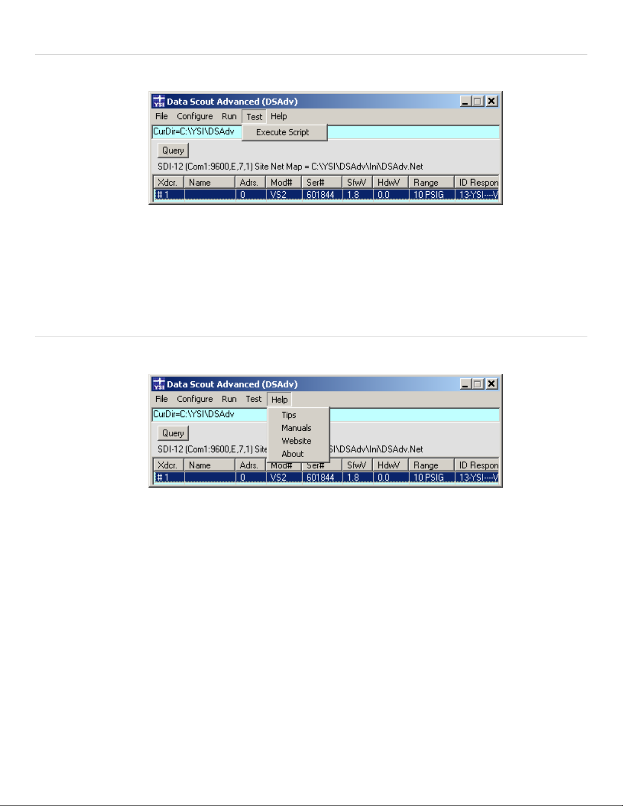
3.7 THE TEST FUNCTION
The Test function, selected from the Data Scout Advanced main menu leads to a sub-menu with only one item (figure 3.15).
Figure 3.15
The Execute Script function is available to users who are familiar with the use of low-level transducer commands and responses. It
allows the user to write their own Scripts (also called Command files) which are simple text files that contain any sequence of
transducer commands and other meta-commands to control the script itself, such as looping, inserting delays and pauses, etc.
For pictorial examples and more information on using the Execute Script function, see Chapter 5.
3.8 THE HELP MENU FUNCTIONS
The Help menu selection on the main menu leads to help information for Data Scout Advanced (figure 3.16).
Figure 3.16
All Data Scout Advanced windows provide ToolTips as the primary help information for each control, label, and display field. Simply
hover the mouse cursor over each item to see what it is and how it is used. Since menu items have no ToolTips of their own, a special
MenuTips status bar (at the bottom of the window) will provide a similar brief description of each menu item selected. Think of
MenuTips as showing the “history” of the last menu item selected, rather than as a prompt to advise what to do next (as the status bar
at the top of window, and the ToolTips, generally do).
YSI Incorporated Data Scout Advanced 25
Page 30
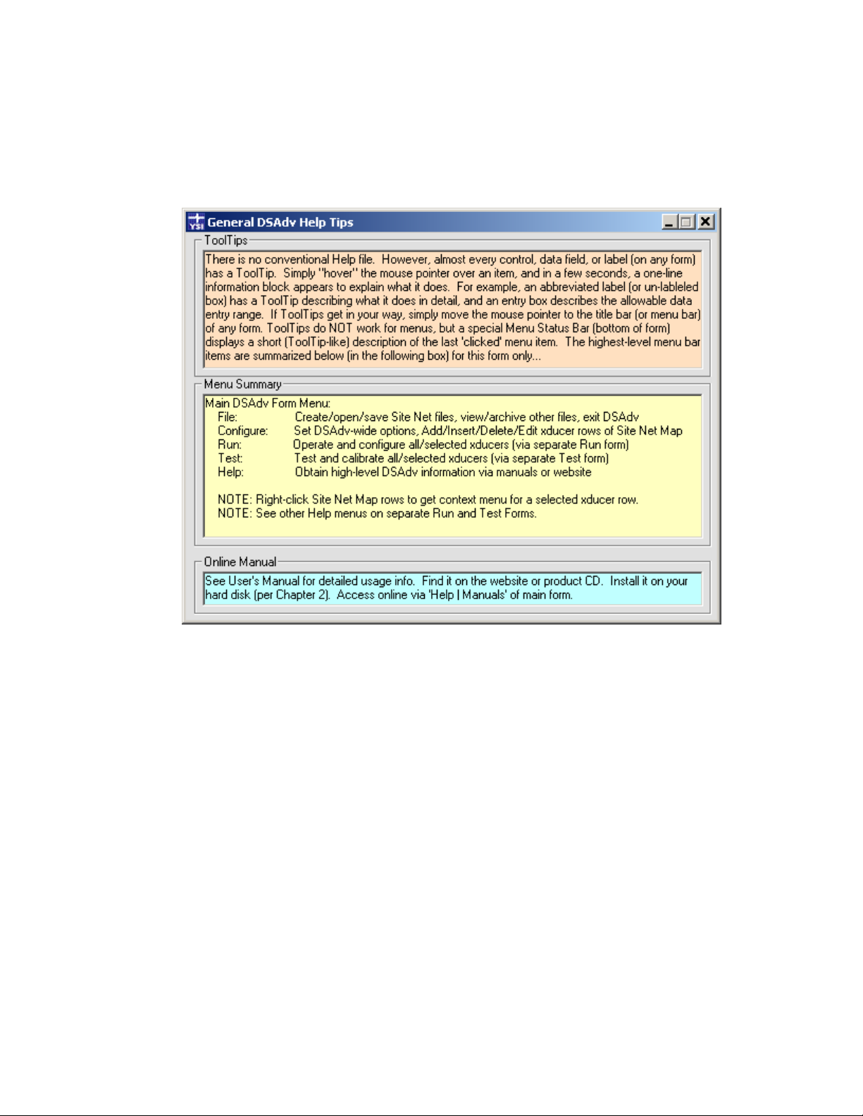
3.8.1 HELP TIPS
The Help | Tips function displays a window that summarizes information about various Data Scout Advanced Help features (figure
3.17).
The first panel contains information about ToolTips in general. The middle panel describes all the major main Data Scout Advanced
window menu bar items. The last panel describes ways of obtaining the Data Scout Advanced Operations Manual
Figure 3.17
YSI Incorporated Data Scout Advanced 26
Page 31

3.8.2 HELP ACCESS TO OPERATIONS MANUAL
The Help | Manuals menu opens the full text and color illustrations of the complete Data Scout Advanced Operations Manual. Before
this works, Data Scout Advanced must be configured to find the manual (section 2.1.1)
3.8.3 HELP ACCESS TO YSI WEB SITE
The Help | Website menu provides access to the YSI website. Use this selection to get the latest published information on the Level
Scout.
3.8.4 OTHER HELP
The Help | About menu selection, opens a window that shows the current user level and version of Data Scout Advanced. When
seeking support for Data Scout Advanced, it is useful to give all this information to the YSI support team.
3.9 HOT-SWAPPING TRANSDUCERS
Data Scout Advanced allows you to “hot-swap” a transducer. Hot-Swapping is when you unplug an existing transducer whose status is
already visible on the current Site Net Map, and plug in a similar transducer with the same SDI-12 address.
3.9.1 THE PROPER WAY TO “HOT-SWAP” A TRANSDUCER
It is best to “hot-swap” a transducer when only the “main” Data Scout Advanced form is active and that form is idle (i.e., it is currently
NOT executing some menu function that sends commands to a transducer – which is most of the time). Then, follow these steps:
• Unplug the desired transducer from its serial port plug
• Plug-in another transducer with the same SDI-12 address
• Immediately Query that transducer (i.e. highlight the changed transducer, right click the Site Net Map to get that transducer’s
Context menu, and then execute its Query item.
For the last step, it may be easier just to click the Query button, which queries the affected transducer and any other transducers
currently on the Site Net Map. Either way, you are done after a successful Query of the affected transducer, as Data Scout Advanced has
replaced all the information from the original transducer with that from the new transducer.
If you should accidentally plug-in another transducer with a different SDI-12 address, errors (figure 3.18) occur several seconds after
you perform the Query step above.
Figure 3.18
Note that the Site Net Map’s displayed information row for the affected transducer still contains the original address (Adrs.=1), but
most other fields contain question marks (?) to indicate that transducer’s Query failed. Recovery is possible if you perform the
following steps.
If only one transducer is defined on your Site Net, you can correct your mistake by executing the Who are You? command on the
transducer’s context (right-click) menu or on the main Configure menu while the transducer is highlighted. After a short delay, the
YSI Incorporated Data Scout Advanced 27
Page 32

original transducer’s Adrs field is replaced with the new address for the new transducer. After this, simply Query again to read all the
information from the new transducer. If there are multiple transducers on your Site Net, then it is necessary to perform the ‘File | New’
function from the “main” menu instead. You must click the Auto Disc button, follow all the prompts carefully, and then wait for all
transducers to be recognized. In this case a Query is already done for you, but you can always click the Query button again to be sure
that the latest information is read from all transducers. Each transducer on your serial port’s network must have a unique address, and
operate at the same baud rate, for this to be successful. If Auto-Discovery fails for one or more transducers, some my have non-unique
addresses – or some may be set to operate at different baud rates. The best way to troubleshoot such cases is to connect just one
transducer at a time to your network, and use Auto-Discovery to weed out non-working units or find other incompatible differences
in the transducers.
4.0 OPERATING TRANSDUCERS (RUN)
This chapter details the Run function which operates all or selected transducers on the current Site Net Map. It is also used to
Configure (view/edit) all user-visible internal transducer options. Chapter 3 described how to activate Run from the main Data Scout
Advanced window’s menu. In this chapter, the separate Run window, with its own unique menu bar, status bar, visual control frames,
data display, MenuTip status bar, and other associated windows are described in their fullest functional detail with pictures and
examples.
4.1 INTRODUCTION
Run’s data acquisition function is able to acquire various kinds of “live” data (on demand, continuously, or periodically) from any or
all of its assigned transducers. These acquired data are displayed in a selectable format (spreadsheet-like table, trend plot or both) and
may also be optionally recorded (i.e., written to a disk file in one of two useful formats).
The Run window can also configure tests to load into the Level Scouts. Such transducers may then be deployed and moved to field
locations, where they can autonomously acquire and record (log) the test data that they were programmed to collect. Later, these
transducers can be reconnected to a PC to allow Data Scout Advanced to extract all data. Data Scout Advanced also records these
extracted data to files and can display them in table, AutoLog plot format, or both. A portable PC with Data Scout Advanced installed
may be easily moved from site-to-site for servicing remote transducers or the transducers themselves may be moved to a central PC site
for test programming and data extraction. If the portable PC solution is impractical, then a subset of Data Scout Advanced software,
Data Scout Mobile, is available separately for use in an handheld PC running Windows Mobile
All data files the Run window generates (whether “live” recordings or extracted “AutoLog” data) are text and can be viewed directly by
a text editor or spreadsheet program. They may also be post-processed and plotted by the Playback application (DSPlay.exe).
The Run window’s Configure menu permits every user-visible option of a single selected transducer to be displayed and edited as
necessary. Whenever these options are modified the user may elect to store the changed value back to the selected transducer or
broadcast the change to all the transducers assigned to the Run window. Configuration data affecting the transducer are remembered
in the transducer’s own persistent (non-volatile) memory. The Run window remembers its own internal operating options
persistently by writing a file (Run.ini) when it exits. These options are restored the next time the Run window is started.
To activate the Run function, click the Run menu item on the main Data Scout Advanced window to reveal a submenu with two items
in its top section and one item in its bottom section (figure 4.1).
®
2003 SE and has a compact flash slot..
Figure 4.1
YSI Incorporated Data Scout Advanced 28
Page 33

For the All Transducers sub-menu item, there is no need for any transducer to be highlighted on the Site Net Map of the main window
since the term ‘All’ means all working transducers. However, if any transducers on the main Data Scout Advanced window are not yet
working (i.e., have not been successfully queried to fill in their necessary ID string information) they will not show up on the Run
window until they are working.
Selecting the second Run submenu item labeled Run | HiLi Xdcr(s) requires that one or more transducers be selected (highlighted) on
the main Data Scout Advanced window’s Site Net Map before it is chosen. Click any transducer row to select it alone.
Either selection will open the Run window (figure 4.2).
Figure 4.2
In figure 4.2, the Run window’s menu bar and Acquire control frame buttons are all enabled and ready to start the Acquire function
immediately. During a short initialize period (immediately after Run function is initiated for the first time during the current Data
Scout Advanced session), these options will be disabled. This period may last for several seconds, depending on the transducer types,
number of transducers, and their common baud rate. The operating mode, write-protect status, and current pressure/level and
temperature units of each transducer are determined during this period. It provides Run with all the information it needs to operate
these transducers and display the data from them correctly.
The Run window may also be moved anywhere on the screen after it starts by dragging its title bar. Its size may also be altered by
dragging its boundaries. Thereafter, Data Scout Advanced remembers its new size and new location.
The third Run submenu item labeled Run | All Xdcrs (Emergency) is rarely used. When selected, it operates just like the first submenu
item, except that it enters the Run window even if one or more Query operations have failed on the main Data Scout Advanced
window. It also bypasses reading transducer data during the Run window initialize period described above. Instead, it sets default
values for each transducer as follows: (1) it is assumed protected (locked), (2) it has psi pressure units assigned, and (3) it has C°
temperature units assigned. This emergency entry is very useful to quickly view or reconfigure some transducer parameter with the
Run window’s Configure menu. It is also used to “repair” a failed firmware update operation (section 4.2.7).
Notice that whenever the Run window is visible and active, the Configure, Run, and Test menus on the main Data Scout Advanced
window are unavailable for use. This essentially prevents unwanted changes to the site network configuration while the Run window is
active. It also prevents the Run window (and other Test windows) from being active at the same time.
4.2 THE RUN WINDOW’S FUNCTIONS
The Run window has its own title bar, menu bar, and status bar. These are independent of similar ones on the main Data Scout
Advanced window. Most of its menu functions are also duplicated, for convenience, as visual controls found in the control frames
(rectangular boxes) labeled Acquire, Display, Record, and AutoLog that appear below the window’s status bar across the middle of the
window. These controls act as convenient shortcuts to the equivalent menu items.
The Run window also has its own spreadsheet-like data table (list view) control, but this feature has an entirely different function than
the similar Site Net Map on the main Data Scout Advanced window. On the Run window this table displays the latest samples of data
as they are acquired “live” from any transducers or when they are extracted from stored AutoLog tests. In the Run window example
above, no data were acquired yet, so these display table cells were only filled with “placeholders” showing what kind of data is
YSI Incorporated Data Scout Advanced 29
Page 34

eventually displayed there (e.g., pdat for pressure data, pun for pressure units, etc.). When the Acquire function is started, these table
cells are updated with actual “live” data. An alternate Plot display method for displaying acquired data may be selected instead of (or
in addition to) the Table display. The Plot display causes a large rectangular graphic window to hide the display table although its
Xdcr. column always remains to allow individual transducer rows to be selected by clicking them. A Both display type allows both the
full data table and the plot surface to be visible together.
The Run window’s menu functions (and equivalent visual control frames) affect only those transducer(s) assigned to it. However,
some menu functions require that only a single transducer be selected (highlighted) by clicking its row (in the Xdcr. column) of the
data table.
4.2.1 RUN WINDOW’S FILE MENU
The Run window’s File menu has two submenu sections (figure 4.3).
Figure 4.3
The first two items open a standard Windows
®
Open File dialog window that list files in Data Scout Advanced’s Dat subfolder.
The first item File | View ‘AutoLog’ Data Files has its filter pre-specified for viewing all AutoLog Test Data (.atd) files containing data
extracted from Level Scout’s tests. Any comma-separated-variable files, created at the same time but with a .csv extension, may also be
viewed by changing the filter. If the AutoLog Plot window of display is also selected, a selected .atd file is also plotted as well as viewed
as a text file.
The second item File | View ‘Record’ Data Files has its filter pre-specified for viewing all “live” recorded data files in the current
specified Record format (.txt or .csv). Whichever type is initially selected, view the other type by changing the filter. These files cannot
be plotted here, but the Playback functions can plot them.
In either case above, when a file name is selected and then opened, that file will be opened in the default text editor.
Selecting the third item File | Playback Any Data Files causes the Playback application (DSPlay.exe) window to be activated in its own
window. This application has its own File menu (and other menus), and is designed specifically for generating secondary tabular
report files and graphic plots from any data file generated by Data Scout Advanced. It is also capable of performing various Convert
operations on its selected data file. One of these can compensate absolute pressure data obtained from Absolute Level Scout(s) by
associating it with data from another recorded data file obtained from a BaroScout located at a known elevation from the liquid surface
of any well or lake containing the Absolute Level Scout(s) to be compensated. These reference barometer data must be recorded at the
same time (approximately) as the level transducer(s). This Playback application is described fully in Chapter 6.
An Exit item is found in the last section of the File submenu. This item’s only purpose is the exit the Run window. After this Run task
exits, the previously dim Configure, Run, and Test menus on the main Data Scout Advanced window are made available for use again.
If data acquisition is in progress when Exit is requested, the user is warned with a warning message indicating that Exit is not possible
(figure 4.4).
YSI Incorporated Data Scout Advanced 30
Figure 4.4
Page 35

The user must then click OK on this status window to dismiss it, and then click Off in Acquire frame, before the Run window can
successfully Exit. A similar warning occurs if the user tries to Exit too quickly before Run completes its one-time startup initialization
period.
4.2.2 RUN WINDOW’S ACQUIRE MENU AND CONTROLS
The Run window’s Acquire menu has four sections (see figure 4.5).
The top two sections contain functions that control the “live” acquisition and display cycle of the Run window. These menu items also
have shortcuts in the form of controls in the Acquire frame located just below the status bar. The central light-green entry box labeled
Period allows for inputting the continuous scan’s frequency in seconds (figure 4.6). See the ToolTips of all these controls for tips and
rules for using them.
Whether using the menu items, keyboard shortcuts, or the easier-to-use push-buttons, the user can cause the Run window to make
one single scan of the transducers or start (turn On) or stop (turn Off) a continuous Acquire/Display cycle with an adjustable period.
The third section of the Acquire menu contains several Measurement options that can be individually checked or unchecked. Checked
options select internal transducer measurements that will be acquired and displayed “live” during the particular acquisition cycle
chosen. Un-checking an item de-selects its corresponding measurement. Whenever a measurement’s option is changed, the Run
window’s data display is rebuilt to show only the display columns for those measurements currently-checked. These Measurement
Options as well as the Acquire Period value are persistent which means that they are saved in a file (Run.ini) when the Run window
exits. Such options are restored the next time the Run window is activated. The On and Off Acquire options are not persistent thus
the Run window always starts with Acquire Off.
To start or stop acquisition (and display) of all configured measurements at any time, select the desired visual button in the Acquire
frame. Selecting the 1 button (or Acquire | Single menu item) causes only one single-cycle of all selected data to be scanned and
displayed on demand. Select the Off button (or Acquire | Continuous Off menu item) to end this single cycle early without
completing a complete scan of all configured measurements. To start continuous (cyclic) scanning of the data click the On button (or
Acquire | Continuous On menu item). Click the Off button (or Acquire | Continuous Off menu item) to stop this continuous
acquisition cycle. Any continuous scanning in progress will be repeated according to the current setting of the Acquire Period (in
seconds) value that is displayed in the middle (light green) text box in the Acquire frame. A zero (0) value causes back-to-back
continuous scanning when On is clicked. Select the text box (or Acquire | Continuous Period Set menu item) to change the period.
Figure 4.5
Figure 4.6
YSI Incorporated Data Scout Advanced 31
Page 36

Either will allow the user to edit the text box directly, after which the user must press <Tab> (or click outside the text box) to make the
change effective.
When Acquire is in progress, for a single scan or scanning continuously, the left-most box (under the Acquire label) changes from
white to bright green, and begins to count scans of all selected measurements (figure 4.7). The integer part counts the number of whole
scans acquired. The fractional part indicates the particular measurement number (1-7) currently being scanned. In the example
below, Acquire is scanning continuously, since the On button is dimmed (can not be selected). Also, it is currently scanning the 1
measurement of the 8th overall scan. If scanning stops entirely, the Off button will be dimmed, and the counter box will show its final
achieved scan count on a white background.
A non-zero Acquire Period value (in seconds) that is less than the time it takes to actually make a
complete scan of all selected measurements will result in a nearly continuous scan. A small pause
between scans, with the Scan Count box displayed briefly yellow (200 msec), indicates this. Set
Acquire Period to zero for a true continuous scan with no pause.
NOTE:
Figure 4.7
st
NOTE:
Select the Scan Counter box to clear its scan counter to zero if Acquire is currently off. This relative
counter has no purpose except as an indicator.
Figure 4.8 below, is an example of a Continuous scan in progress where the Period: text box contains a non-zero Acquire Period value
(60 sec.). That box will become bright yellow if such a period is currently active and counting (or remain light-green if acquisition is
not continuously On). The leftmost Scan Counter box will be bright green during any scanning of all selected measurements but turns
bright yellow during any idle time while Acquire is waiting for the next period (time of a next scan) to begin.
Figure 4.8
Once an Acquire cycle has been started it will be impossible to Exit the Run window, or change any measurements acquired and
displayed, until acquisition is stopped by selecting Off and the scan in progress is finished. The continuous Period box’s value may be
changed any time. However, a <Tab> key (or mouse click outside the box) must be entered before the change is recognized. If an
Acquire cycle is already in progress, it may take another completed cycle before the change takes effect visibly. Clicking the [1] button
or the On button while a single or continuous cycle is already in progress, is ignored. However, clicking the [1] button during the idle
time between periodic scans will cause an immediate single scan and the continuous periodic cycle will end as if Off had been clicked.
NOTE:
The Level Scout allows scanning of their Raw Pressure Volts or Raw Temperature Volts
measurement data ONLY if the transducer is Unlocked. The resulting bad values of “****” are
displayed if their acquisition is attempted while the transducer is Locked. Use Configure | Lock
Access (HiLi Xdcr) to change this state.
YSI Incorporated Data Scout Advanced 32
Page 37

In figure 4.9, the Run window is shown with only a single measurement (P) selected. Here, the continuous “live” acquisition cycle
(with fastest possible scan period = 0) is shown in progress (i.e., count box = 3.1 and bright green) the count indicates that the 3
st
(and only) measurement, is in progress. Since there is only one measurement, the fractional part of the scan counter never changes
1
when the box is green. The message in the status bar (at top) and MenuTip bar (at bottom) changes frequently to also show current
state of scan.
rd
scan,
In above example, note that the Configure menu, AutoLog frame of controls, and all measurement selection items in second section of
Acquire menu are disabled while acquisition is running. Thus, the user can change the data content of the acquisition only by stopping
Acquire first. After clicking the Off button, changing measurements is accomplished from the second section of the Acquire menu.
However, if the Record function is also On, the user may leave it on during such a change which allows the recorded data format to
change across the length of the recorded file. Special “unit” header/trailer lines are written to the data file when such format changes
occur. These assist the Playback function in handling the complexity of a file whose data content changes dynamically.
Figure 4.9
The empty Test#(name) column of the Table data display is reserved for data displayed when a Level Scout transducer has its
“AutoLog” data extracted (described later), and the Table or Both display type is selected.
4.2.3 RUN WINDOW’S DISPLAY MENU AND CONTROLS
The Run window’s Display menu has two sections (figure 4.10). The top section allows one of three display types to be selected. The
currently selected display type is checked. The bottom section contains a single selection labeled Options, which causes an Option
window to open to show the current options available for the currently selected type, and to allow changes to these options.
Figure 4.10
YSI Incorporated Data Scout Advanced 33
Page 38

A separate frame of visual controls in the Run window, labeled Display, has all the exact same functions, but with ToolTips. The light-
green list box shows the currently selected Display type, and its right arrow button allows the user to select a new type from a dropdown list.
Selecting the Options button in this frame causes an auxiliary Display Options window to open (figure 4.11). This option window lets
the user select other options of the currently selected Display type, but the Table type does not currently have any special options of its
own thus the empty second frame. Ignore the first frame for now (it’s for displaying extracted AutoLog data which is described later).
For some applications a graphic display type is a more suitable format than the default spreadsheet-like tabular format. By clicking the
arrow in the list box of the Display frame, and selecting the Plot display type, data may be displayed as a graph. This may be a Trend
Plot of “live” acquired data or an AutoLog Plot (figure 4.12).
Figure 4.11
Figure 4.12
YSI Incorporated Data Scout Advanced 34
Page 39

NOTE:
The Xdcr. column (of the original Table display) remains exposed (on the left) when a plot display pane
The desired Plot format (AutoLog or Trend) may also be explicitly selected by clicking the Options button in the Display frame, then
selecting it in the second frame of a Display Options window (figure 4.13). The option window also allows one to select other options
of the currently selected Plot format (e.g., scope, symbol size and density, background colors, etc.). Explore the ToolTips of these
option windows for more information on the purpose of each option frame, field, and button. Plot options can also be obtained by
clicking the plotting surface.
appears on top of it. This allows individual transducers to still be selected (by clicking their row) which
is required to perform various other transducer-specific Configure menu functions of the Run window.
Clicking a row is also used to select the scope of a Trend plot: either a single transducer’s measurements
or data from all transducers plotted together (by clicking the bottom blank row). A similar function
chooses to plot the latest extracted or selected AutoLog file (see section 4.2.5.2).
The first frame of Display Options can be ignored for now as it determines if AutoLog data (to be described later) are to be displayed
when extracted from the Level Scout. The type of plot (Trend or AutoLog) is usually selected automatically. However, the second
frame lets you also choose it explicitly, which is sometimes useful when both are possible. The window also displays other options that
are appropriate to that particular selected plot type. In the Trend case shown, the user can also select its scope here.
The All Transducers Trend format can be confusing if there are many transducers, as there is room to show labeled axes for only four
measurements. The user must mentally divide the printed range annotation of each measurement by five to establish the value of each
of the five standard grid lines shown. If the Pressure (P) and Temperature (T) measurements are not selected, then other selected
measurements have their axes labeled instead.
Figure 4.13
YSI Incorporated Data Scout Advanced 35
Page 40

Clicking the Scales button on this window reveals other advanced options for overriding plot scale end-points normally chosen
automatically (figure 4.14). Clicking the Options button (on right) will restore the original second frame of main options. Once any
Scale End-Points have been edited they will persist until the Plot format is reselected for the display which restores the original
“automatic” scale end-points. When a single transducer is the Trend scope, its automatically determined scale end-points are
appropriate to the range of that transducer. However, when “All” transducers are plotted together, the scale end-points are
“amalgamated” (i.e., they range from the lowest end-point of the lowest transducer range, to the highest end-point of the highest
transducer range), and for Pressure (P) and Temperature (T) measurement they may vary in units as well.
The user can exclude any measurement from the current plot by clicking its name label (P, T, Tb, Vs, ...) on the Scales window. This
method removes the measurement from the plot only, without affecting the selected measurements that continue to be acquired and
recorded. Clicking the measurement’s name label again restores it to the plot.
Any changes to plot options will cause a Trend plot to restart (at zero time). So, be sure to make all changes and test them ahead of
time, if it is necessary to see plotted Trend data uninterrupted for extended periods.
There is a third Display type, called Both, that reveals both a Tabular Display and Plot Display in the same window. For some
applications this is particularly useful since this allows the user to view the graphic representation of data and the most recently
acquired/extracted digital tabular printed values.
Examples of this display type and its option windows are shown on the following page (figures 4.15 and 4.16). As before, the option
windows can be obtained by clicking the Options button, by making the Display | Options menu selection, or by clicking the plotting
surface.
Figure 4.14
YSI Incorporated Data Scout Advanced 36
Page 41

Figure 4.15
Figure 4.16
YSI Incorporated Data Scout Advanced 37
Page 42
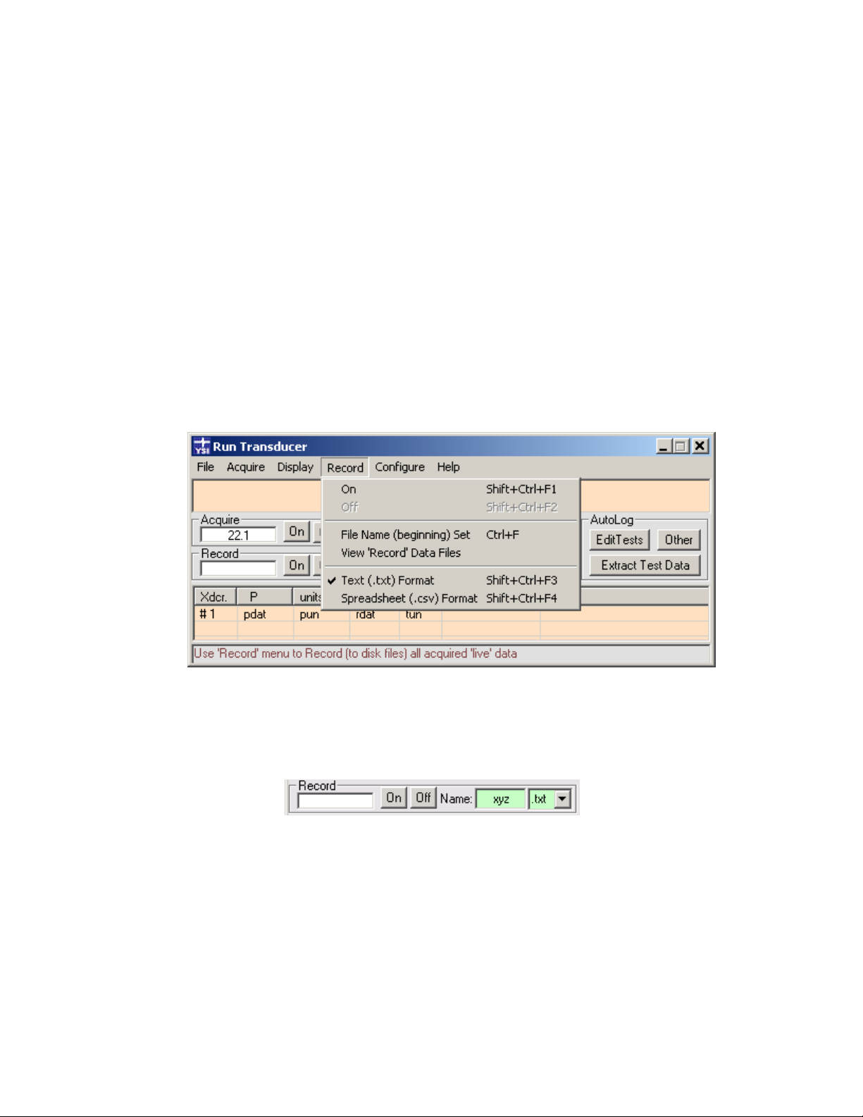
The only significant option difference is the addition of a slider control that allows the delay between successive tabular display updates
to be varied. However, this is only useful for displaying AutoLog data (described later). The other Plot options are the same as for the
Plot-Only Trend graph.
The original Table Display type on the Run window can only be resized in the horizontal direction though its various tabular display
columns can be narrowed or widened by dragging their header boundaries. However, when a Plot (or Both) Display type is selected
the Run window may be resized in both horizontal and vertical directions. These changes in size are persistent.
The plotting surface will always resize itself appropriately as the horizontal and vertical dimensions of the Run window are changed
(except when “live” data is being acquired and also displayed on a Trend graph). Really small plotting surfaces are possible, but are not
very practical from a readability standpoint. Thus, it is recommended that the user enlarge the Plot Display to near full-screen size in
order to best view a plot’s labels and annotations. The small annotation text will use a progressively larger font as the window’s width
is increased. The line spacing of annotation text will also increase with window height. A few seconds after the window is resized, any
selected plots will be replotted.
4.2.4 RUN WINDOW’S RECORD MENU AND CONTROLS
The Run window’s Record menu item reveals a submenu in three sections (figure 4.17). The top section turns the function that
records “live” scans to data files, On or Off. The middle section allows the “beginning” name of the next recorded data file created to
be defined and also allows any existing recorded data file to be selected and viewed. This latter function is also duplicated (for
convenience) on the Run window’s File menu. The bottom section sets the format of the next recorded data file created to either a
simple block-per-scan text format (.txt) or to a spreadsheet row per scan format (.csv). Examples of both formats are shown at the end
of this section.
Figure 4.17
These menu items duplicate functions also available in the Record frame of visual controls located just below the Acquire frame (figure
4.18). Whether using the menu items or the frame of visual push-button, the Run window can record any acquired “live” data scans
for short or extended sessions.
Figure 4.18
Select the On button (or Record | On menu item) to “create” a new recorded data file. It opens a new file whose name begins with
whatever is currently displayed in the light-green text box labeled Name, and ends with a file extension and internal format specified by
the rightmost list box. Time and date are added to make the file name unique. Using the example above, a file named of
xyz_<date>_<time>.txt would be created in the Dat subfolder of the path where Data Scout Advanced was installed (normally
C:\YSI\DSAdv\). The complete path name of a typical recorded data file would be C:\YSI\DSAdv\Dat\xyz_2006-9-21_13-49-08.txt.
Click the Off button (or Record | Off menu item) to stop recording and close the currently open data file. Any such data file may
contain no acquired data (if Acquire was never turned On while file is open) or it may contain data obtained by one or more Acquire
sessions (i.e., in case Acquire turned On and Off once or several times during the time Record file is open).
Click the Name: text box (or Record | File Name (beginning) Set menu item) to change the “beginning” characters of the name of the
data file that will be created next. After editing the text box, press <Tab> (or click outside the text box) to make the name change
YSI Incorporated Data Scout Advanced 38
Page 43
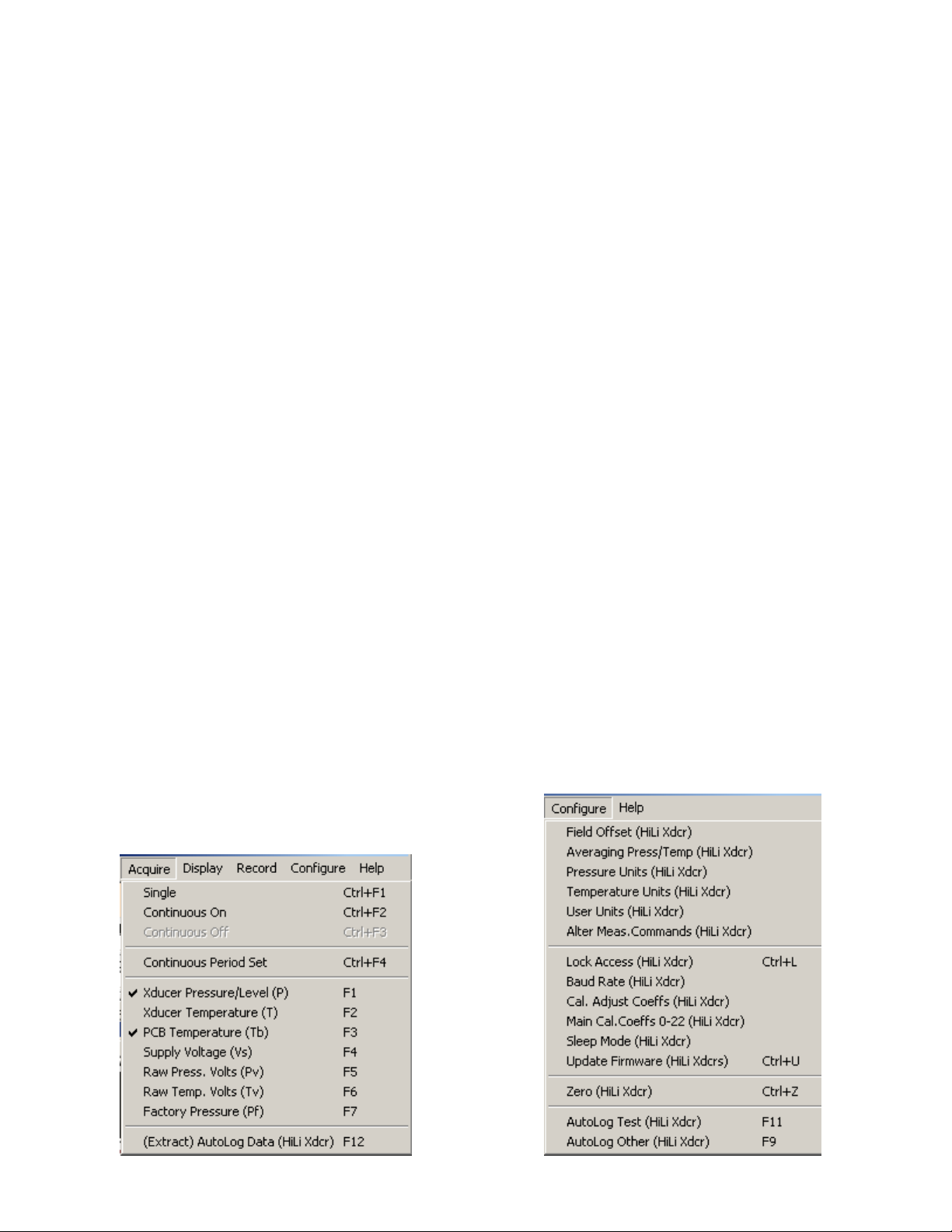
effective. Any name is permitted as long as it can be part of a valid Windows® file name. If the name is left blank, then the next
recorded data file name will begin with an underline character followed by the <date> and <time> fields, all separated by an underline
character.
As soon as a new file is created (and a set of header lines describing the transducer and other Data Scout Advanced parameters are
recorded to it) it is closed. Thereafter, it is reopened as a text file (with the append option) only when a scan is ready to be recorded to
it after which it is immediately closed at the end of a complete scan. This makes the file less vulnerable to the user forgetting to close it
when finishing a recording session since it is always incrementally written by appending to it and it remains closed most of the time
between scans (particularly when using the Demand (i.e., 1 button) acquisition or Continuous (i.e., On button) acquisition with a
non-zero Acquire Period).
When the Record function is On, the leftmost box changes from a white background to a bright green background. A relative time
stamp is displayed for each sub-scan of a particular measurement that is recorded. This box remains bright green until the Record
function is stopped by clicking the Off button. The time stamp is also written to the data file before each measurement’s sub-scan. As
the time stamp grows, its format and resolution changes from fractional sec, to min:sec, then hr:min:sec. in order to continue to fit
into the box.
The text box labeled Name, containing the File Beginning Name, is normally light-green while Record is Off. If Record function is
On, and a measurement scan is also currently being acquired, it turns bright-green. If the Record function is On, and a measurement
scan is not currently being acquired, the box is bright yellow indicating that file has been created, but is not currently being written to.
The particular Record data file format selected depends on how the recorded data will be used. The two formats are both simple
sequential text files. However, the one with the .txt extension, records data in a more directly human-readable block format with each
particular measurement’s sub-scan (a time stamp followed by a sample of the measurement(s) from each configured transducer)
written to a separate line of the file. At the end of complete scan a blank line is written. This so-called block format repeats for every
complete scan.
The format with the .csv extension (comma-separated variable text file), records the same basic data but all these data are contained on
the same spreadsheet row (text line). That is, each individual measurement’s time stamp and sub-scan is written on the same
spreadsheet row. There is no blank line dividing complete scans from sub-scans. Commas separate each datum to make it easier for a
spreadsheet program to read and display the file.
The Record options for File Name and File Format are persistent, in that they are saved in a file (Run.ini) when the Run window exits.
Such options will be restored the next time the Run window is activated. The On and Off Record options are not persistent thus the
Run window always starts with Record Off.
4.2.5 RUN WINDOW’S AUTOLOG FEATURE
The Run window’s AutoLog menu items are at the bottom of both the Configure and Acquire menus (figures 4.19 and 4.20).
YSI Incorporated Data Scout Advanced 39
Figure 4.19 Figure 4.20
Page 44

To make it easier to find and use these functions, a visual control frame labeled AutoLog appears in the Run window to integrate all
these functions in one place (figure 4.21).
Figure 4.21
Note:
A particular transducer row in the Xdcr. column of the Run window’s must be selected (highlighted) before
selecting any of these AutoLog buttons (or menu equivalents), as these functions focus only on a single Level
Scout.
YSI Incorporated Data Scout Advanced 40
Page 45

4.2.5.1 CREATING AND EDITING AUTOLOG TESTS
The Edit Tests button lets the user Configure (define and/or edit) one or more tests that can be defined in the selected transducer.
Clicking this button opens the AutoLog window open (figure 4.22). This window permits the user to view and/or edit any or all of the
AutoLog tests (numbered 1 - 16) that are defined inside the selected Level Scout.
Figure 4.22
On top of the initial AutoLog window, a temporary status window may appear during the process of reading all (up to 16) tests inside
the transducer. When this operation is done, the AutoLog window is enabled, allowing the user to create new tests or to edit existing
tests.
Notice the three options in the frame of controls located at the upper left of this window. Although the Edit Test function is currently
selected, two other configurations (Extract Test Data and Other) can be chosen at any time. These functions are described in the
following sections.
Notice the Send and Exit buttons at the upper right of this window. The Send button can be selected anytime there are one or more
edit (pink) changes made that need to be sent to the selected transducers or broadcast to All transducers assigned to the Run window
per the Apply to: frame at the bottom right of the window. To return to the Run window, select the Exit (or X) button. If edit (pink)
changes have been made, the user will be warned if exiting the window is attempted without sending the edits to the transducer first.
The status of all tests appears in the frame titled Summary of Existing Tests, which is a collection of tabbed sections. Any of these 16
tests may be viewed, one at a time, by clicking the desired test number tab. The large white test status pane of the selected tab will show
a summary report of that test’s parameters. Such parameters cannot be edited directly in this display-only pane. Instead, all editable
parameters also appear in the frame titled Configure/Edit Test “n” (where n is the selected test number). Select each of its four tabs to
view and edit all of the current test’s parameters. These parameters include:
Time: Specify begin and end times: None, Absolute, or Relative
Scan: Specify period, type (e.g., linear, logarithmic, averaged, event-based), and other scan options (degree of averaging,
etc)
YSI Incorporated Data Scout Advanced 41
Page 46

Measure: Specify any or all measurements to be logged: transducer level or pressure (P), transducer temperature (T), printed
circuit board temperature (B), and battery voltage (V)
Other: Give tests an optional name (up to 18 chars.) or Vacate any Idle or Done test. The program will warn the user to
extract the data from Done tests before vacating them.
The Time tab contains options for entering the Begin and End date/times of a new test, or for displaying the date/times of an existing
test (figure 4.23). Enter the test date/times in an Absolute or Relative format. The None selection leaves date/time undefined. The user
cannot change the Begin time of a test once it is scheduled to run. However, the user may change the End time of an existing Active
test to force it to end earlier than originally specified. Setting a test’s Relative End time of 0_0:0:0 will usually end it immediately (after
Send button is selected) if the test is already Active.
Figure 4.23
Only Absolute dates/times of tests are actually sent to (and understood by) the Level Scout. Relative entry is a user
convenience provided by the software. A Relative Start date/time of a test is relative to when the user presses the
Send button. A Relative End date/time of a test is relative to its previously specified Relative (or Absolute) Begin
date/time. Thus, a Relative Begin date/time of 0_0:0:5 (default) starts the test 5 seconds after it is sent to the Level
Scout. A Relative End date/time of 0_0:5:0 (default) stops the test 5 minutes after it was started. Using Relative
values is often simpler than trying to enter six exact numbers as accurate Absolute values. Note that relative dates
have no year or month field, but have only a single day field with a possible value of 0 to 99 relative days. The
necessary conversion from relative to absolute date/time is made just before the values are transmitted to the
transducer. Thereafter, only the equivalent absolute value is displayed.
Note: ABSOLUTE vs. RELATIVE DATE/TIME
YSI Incorporated Data Scout Advanced 42
Page 47

The Scan tab accepts a relative time Period (in days, hours, minutes, and seconds, between the starts of each scan) and a Scan Type
selection for a test (figure 4.24). The most common Scan Type is Linear, meaning that the scans are evenly spaced in time at a fixed
constant period. The period has a days field that can be specified as 0-99 days. The seconds field of the period may have a fractional
part allowing it to vary from 0 to 59.99 seconds. The minimum period that can be specified between scans is 0_0:0:0.01 (1/100th of a
second) but using such a short period will seriously limit the life of the battery and the total test time, as the finite memory will also be
used up very fast.
Figure 4.24
For the Logarithmic scan type, the period starts small (0_0:0:0.01) and logarithmically lengthens until it reaches the final terminal scan
period specified after which the period remains constant at this terminal value until the test ends (figure 4.25).
Figure 4.25
Figure 4.26
Figure 4.27
For the Linear-Averaged scan type, the extra Average Count entry field limits the number of scans actually logged, while acquiring data
at the specified higher period but only logging less-frequent single scans containing the averaged values up to that point (figure 4.26).
For the Event-Based scan type, data scans are acquired at the specified period, but logging occurs only when a particular specified
datum (pressure or temperature) changes by the specified relative (delta) amount or by default after the specified number of scans (in
the Default # Scans field) has occurred without a preceding delta change (figure 4.27).
YSI Incorporated Data Scout Advanced 43
Page 48

The Measure tab allows the user to select any or all of the available measurements (pressure, transducer temperature, printed-circuitboard temperature, or supply voltage) to be made for each acquired scan of the test (figure 4.28). The supply voltage always measures
the internal battery voltage even if external power is supplied. Simply check the check-box corresponding to each desired measurement
to include it in each logged scan.
Figure 4.28
The Other tab (figure 4.29) has two unrelated entry/display items:
A descriptive Test Name (enter up to 18 characters, blanks are OK). Enter the string “part#<Tab>” to get the actual
transducer’s part # in the box as a test name.
A check-box that, when checked, causes the entire test to be set to the Vacant state, if its current state is either Idle or
Done. An Active test may be made Done quickly by setting its End date/time to Relative 0_0:0:0. A Pending test
may be made Done by setting its Begin and End date/times to Relative 0_0:0:0.
Note that all editable data fields are light green. If changed, they turn pink as does the test as a whole. The Send button also turns pink
indicating that, by clicking it, all changed test parameters will be transmitted to the transducer(s) per the Apply To: frame. The Send
button turns bright red after being selected until all edited changes have been sent to the transducer(s). After edit changes are sent,
their fields return to their original light green unedited color.
Figure 4.29
Double-clicking the display-only white (or pink) test status pane for the selected current tab causes
that test’s parameters to be re-read from the transducer and re-displayed. This function also
removes any previous edits (pink fields) for that test. Double-clicking the outer left, right, or
bottom borders of the test status pane, or the frame title labeled Summary of Exiting Tests,
similarly causes the parameters of all 16 tests to be re-read from the transducer. This function also
removes any previous edits (pink fields) from all tests.
YSI Incorporated Data Scout Advanced 44
Note: HIDDEN CONTROLS
Page 49

On the right side of the Edit Tests window, below the four parameters tab, there may be several different special buttons visible,
depending on the state of the selected test.
If the selected test is Active then a single button labeled End Active Test is visible. In this Active state, the only test parameter that can
be changed via the editing process is the End Time of the test. All other parameters are dim and unchangeable. The End Active Test
button is simply a shortcut for setting the End Time to a relative zero value. Clicking the button causes the Time tab to be displayed (if
not already displayed) and its End Time fields are all changed to “pink” as an indication that they have been set to this new edited
value. Select the Send button to transmit this edit change to the transducer(s).
If the selected test is Pending then a single button labeled Begin Pending Test is visible. In this Pending state, the only test parameters
that can be changed via the editing process are the Begin Time and End Time of the test. All other parameters are dim and
unchangeable. The Begin Pending Test button is a shortcut for setting the Begin Time to a relative zero value (0_0:0:0 days_hr: min:
sec). Clicking the button causes the Time tab to be displayed and its Begin Time fields to be changed to “pink” as an indication that
they have been set to this new edited value. Select the Send button to transmit this edit change to the transducer(s). If another test is
Active, pressing this button may cause that Active test to end. If several tests are Pending, only force the “next” test in sequence to start.
If the selected test is in any state other then Pending or Active, then two buttons labeled Get and Put are visible. These buttons are
particularly useful if the test is currently Vacant or Idle and in the in the process of being created. The Put button may be used to save
the current test’s parameters (as is, in original or edited state) to any file in the Data Scout Advanced Ini subfolder. A dialog box opens
to allow the user to save a named test scenario (.tst) file. Later, the user can use the Get button to retrieve a named test scenario file
and substitute it as the current “edited” state of any other test. Clicking Get causes all of the selected file’s substituted test parameters
to be set “pink” to indicate they have been modified. These buttons allow the user to share tests or test fragments between different
transducers. Click the Send button to transmit these edit changes to the transducer(s).
Any or all modified (pink) test parameters are saved only when the Send button is selected. The Exit button will allow the user to
cancel all changes made.
Normally, only changed (pink) test parameters are written back to the highlighted transducer when Send is selected. However, the
Apply To frame (in lower right corner) has an alternate selection allowing the user to broadcast these Test Edit changes to all other
transducers assigned to the Run window (for the same corresponding test number only). This can be a time-saving feature in some
situations.
If any pre-programmed Level Scout(s), which have been loaded with tests, are disconnected from the PC and Data Scout Advanced,
their special AutoLog hardware feature will continue to autonomously “log” (acquire and record) data as programmed as long each
transducer has enough non-volatile memory space available and enough battery power to keep it running. Multiple tests can be
scheduled concurrently. If any test’s begin/end times overlap another’s times you are warned and allowed to abort such changes or you
may choose to proceed anyway. If you allow tests with overlapped times to continue, the starting of a new pending test will terminate any
other test already active. Later, the transducer(s) may be reconnected to Data Scout Advanced. Then, you may Extract (read) the
autonomously “logged” data scans from the transducer(s), and store them as data files on the PC per the instructions in the next
section.
YSI Incorporated Data Scout Advanced 45
Page 50

4.2.5.2 EXTRACTING DATA FROM AUTOLOG TESTS
To Extract AutoLog data from a Level Scout, click (highlight) a particular transducer row on the left-most (Xdcr.) column of the Run
window to choose the subject transducer. Then, click the large Extract Test Data button in the AutoLog frame.
Clicking this button makes the AutoLog window open (figure 4.30). Because the Extract Test Data function was selected, this window
is initially configured with only the controls necessary to permit the user to view or extract data from any or all of the AutoLog tests
(numbered 1 - 16) that are defined inside the selected Level Scout.
On top of the initial AutoLog window, a temporary status window may appear during the process of reading all (up to 16) tests inside
the transducer.
Figure 4.30
Notice the three options in the frame of controls located at the upper left of this window. Although the Extract Test Data function
chosen from the Run window is currently selected, two other configurations (functions) can also be chosen at any time. The first (Edit
Tests) was described in section 4.2.5.1. The Other choice is described below in section 4.2.5.3.
The frame labeled Summary of Existing Tests has the same identical tabbed control as the Edit Tests configuration already described.
This frame also has the same “hidden” controls: double-clicking the display-only white (or pink) display pane updates the current test
or double-clicking the display pane’s outer border updates all the tests. Both functions clear any previous edits (pink fields) for the
affected test(s).
The frame labeled Extract Logged Data for Test “n” (where n is the currently selected test number) has only two tabs (labeled Data
and Units).
The Data tab has two frames. The first frame has a single check-box option that determines whether or not a Comma-SeparatedVariable (.csv) file should also be written in addition to the default AutoLog Test Data (.atd) file for every extracted test. This option
applies to all extracted tests globally (not to each extracted test individually). The second frame of the Data tab has two test boxes
showing the Begin and End scans currently available to extract from the currently selected test. It also requires that the user check a
box in order to request the extraction of that test’s scans. The user can, however, request extraction of more than one test’s data when
the Send button is clicked. The user can also extract other available scans by changing the default Begin and End text boxes.
YSI Incorporated Data Scout Advanced 46
Page 51

All extract requests and option changes on the Data tab turn “pink” just like test parameter changes using the Edit Test function.
Changed fields on the Unit tab do not turn pink since they are simple modifiers of the extract requests on a per test basis.
All extracted AutoLog pressure/level data coming from a Level Scout are downloaded to the PC in fixed units (psi pressure units, degC
temperature units). However, Data Scout Advanced will automatically convert these extracted data to any other pre-selected
transducer units chosen at the time of actual extraction after Send is clicked. It will be these units that are written to PC files. The
default units are those units the transducer has been set to for reading of “live” acquired data. The Units tab (figure 4.31) inherits, and
initially displays, the default units setting for every test when the AutoLog window is first loaded. However, the user may change these
unit settings for each extract request. To extract a particular test’s AutoLog data multiple times, and write each file in different units
and precision, click Send separately for each request.
Figure 4.31
Behind the scenes, all extracted data are written first to a special raw file (XRTD.raw). When extraction is finished (or is aborted), this
non-human-readable hidden file is always translated into an AutoLog Test Data (.atd) file, which contains human-readable text.
Optionally, a Comma-Separated-Variable (.csv) file may also be written, which is readable by a spreadsheet application. All these files
are stored in the Dat subfolder of Data Scout Advanced. The two “visible” files are automatically named using the transducer’s model#,
serial#, test#, plus date and time of file creation (e.g., VS2_012300_Test1_2006_09_30_10_56_11.atd or .csv). After extraction, each
.atd file is automatically displayed in the Run window. If extracting data from more than one test at a time, only the last test extracted
is displayed. However, the user can re-display the other AutoLog files later after exiting from the AutoLog window and returning to
the Run window. There, use the File | View ‘AutoLog’ Data files menu function to view an AutoLog file in the Run window.
If the current Display type is Table, the extracted AutoLog data file will appear on one row of the spreadsheet only.
YSI Incorporated Data Scout Advanced 47
Page 52

Although there are special options in the first frame of the Display Options window (figure 4.32) to allow the speed of the Table update
to be slowed down, and repeatedly displayed, the Plot form of display may be preferred for displaying extracted AutoLog data.
Figure 4.32
The first check box in figure 4.32 (labeled Display AutoLog Data During Extraction) is normally checked. It causes AutoLog data to
be displayed at the time it is extracted and whenever any AutoLog Test Data (.atd) file is opened from the Open File dialog (obtained
by the File | View ‘AutoLog’ Data Files function, by clicking the periphery of the AutoLog control frame, or its label). The second
check box is optional, and determines if a Comma Separated Variable (.csv) file is generated from the extracted data in addition to the
required AutoLog Test Data (.atd) file. This option duplicates one already shown on the Data tab of the Extract Test Data window. If
the extracted data are displayed in the Table or Both format, it may be necessary to adjust the slider to slow down the display update
rate in the table in order to see the individual scans. In such case, click the Again button and then OK to view the most recently
selected .atd file’s data again after each adjustment. Click the Abort button and then OK to stop displaying a very long data file.
NOTE:
If the current Display type is Plot or Both, but the current Plot source selected is for Trend (“live”
acquired) data, extracted AutoLog data is not immediately plotted. To obtain the plot, right-click in
the Plot and select the AutoLog option in the middle of the Plot Options window instead of the Trend
option. Then, click the Again button and the OK button. The previously extracted data file is then
plotted. Any subsequently extracted AutoLog data will be plotted immediately as long as AutoLog
remains selected on the Plot Options window.
YSI Incorporated Data Scout Advanced 48
Page 53

The preferred Display type for AutoLog data is Plot. Once displayed as a plot, the user may increase the window’s size (and thus the
plot surface) in both height and width by dragging the bottom-right corner of the Run window. Also, notice the particular Plot Option
frame in figure 4.33. Open this window by selecting the Scales button in the previous window (figure 4.32). Just as with the Trend plot
examples shown earlier, the user can accept the plot scale endpoints for each datum that are provided automatically, or manually edit
any or all plot scale endpoints. Unlike Trend plots, the user can also manually change the time scale’s endpoints. However, the user
must accept the time units as provided in the .atd file containing the extracted data, which are set automatically according to the time
span of the actual extracted test data. This is time in seconds for small spans, in minutes if the span exceed 120 seconds, in hours if the
span exceeds 120 minutes, or in days if the span exceed 48 hours.
Note that when the AutoLog Plot window is displayed, a Print Plot button appears in the top right of Run window. Click this button to
obtain a printer hard copy of the currently displayed AutoLog plot (in landscape format). The Trend Plot window does not have such
a button because its plotted data does not all exist in a file.
Figure 4.33
A considerable amount of time may pass, after clicking the Print Plot button, before any data appears on
the printer. This is because all the data in the currently selected .atd file must be re-plotted and sent to the
printer. Usually, the only indication of any progress is the appearance of a small printer icon in the
Windows
®
tray.
NOTICE:
The Display Options window for the Plot or Both display types can also be obtained by clicking the “plotting surface” of the Plot. If a
plot is used for displaying AutoLog extracted data the user may need to choose other options in the second frame of controls. First, the
AutoLog radio button must be clicked if Trend has been manually selected instead. Other options affect the color of plot background,
plot symbol density and size, and whether the Print Plot button is selected. As already described, the Scales button provides access to
an advanced feature that lets the end-points of each of the plot scales to be overridden manually by the user editing them. Once you
have changed any Scale End-Points manually, return them to default values by re-selecting the Plot or Both display type again or in the
case of AutoLog plots only, reselect the file again by clicking the AutoLog frame. The user can exclude any measurement from the
current plot by clicking its label (P, T, Tb, or Vs) on the Scales window. Click the name label again to restore the measurement to the
plot.
In addition to viewing the latest extracted AutoLog data file, the user may also access any previously extracted AutoLog data files from
the File menu or by clicking the AutoLog frame title. Either function will open a Windows
All .atd files will be listed in the large white pane by default, and the latest one created will appear in the File Name: list box, ready to
select if the Open button is clicked. Otherwise, select any desired file name, and then click Open or double-click the desired file name.
YSI Incorporated Data Scout Advanced 49
®
open file box.
Page 54

The list box labeled Files of type: may have its arrow button clicked to select another filter (e.g., to view all the .csv files instead). A
selected .csv file is best viewed by a spreadsheet application directly using the Open item on the right-click context menu instead of
clicking the Open button or double-clicking its file name. Any AutoLog Test Data (.atd) file selected for viewing will be displayed on
the Run window according to the currently selected display mode (Table, Plot, or Both). Use the Playback application, described in
Chapter 6, to plot any .csv files directly.
To view the original text report when currently displaying an AutoLog plot, click the plot surface to bring up the Display Option
window. Then, click the View Report button on the right side of the option window to view the plot’s source text report.
The most recent ‘raw’ extraction file (normally hidden) cannot be viewed in Data Scout Advanced by clicking the Open button.
However, it is in a text format, and can be viewed by choosing its special “filter”, labeled All Raw Data files (.raw), in the Files of type:
pull-down list at the bottom of the Open File dialog window. Then, highlight its file name (XRTD.raw) and right-click the mouse.
This reveals a standard Windows
®
context menu that has file-related choices (e.g., Open With and Send To) that permit the user to
view it with any suitable text editor. Viewing this ‘raw’ file is only useful, for diagnostic purposes, if its extraction process failed or was
aborted before completion. Technical support may ask you to do this if they need to analyze error and status messages in this file.
Only the last such file is retained.
4.2.5.3 OTHER (NON-TEST) AUTOLOG OPTIONS
There is still one more button, the Other button, on the AutoLog frame of controls (figure 4.34). It has a corresponding function on
the Run window’s Configure menu as well. Clicking it will cause the following configuration of the AutoLog window open (figure
4.35).
Figure 4.34
Figure 4.35
YSI Incorporated Data Scout Advanced 50
Page 55

Notice the three options in the frame of controls located at the upper left of this window. Although the Other function you chose from
the Run window is currently selected, two other configurations (functions) can also be chosen at any time. These were already
described in section 4.2.5.1 and section 4.2.5.2. The main benefit of this frame is that the user can freely change between the three
configurations of the AutoLog window, without having to return to the Run window, no matter which button opened this window.
This configuration of the AutoLog window shows all other (non-test# specific) status items and associated editable options that can be
changed in the Level Scout. The white status frame shows three items including: Battery status (and options), Memory status (and
options), and Date/Time status (and options). Double-clicking this frame’s title will refresh all the Other status items by re-reading
them from the transducer and redisplaying them. Double-clicking just the label above a particular status box will refresh that one item
only. Three frames surrounding the white status frame allow changeable options of these various items (labeled in light green value
fields) to be edited as needed. White value boxes show status values only and cannot be edited directly. For more information view
the ToolTips of all these various fields for instructions on how to interpret them and edit them.
The only Date/Time option is a check box that allows the user to request that the date/time in the transducer be synchronized with the
PC’s date/time. The user may also be prompted to use this option when tests are uploaded from a transducer if PC and transducer are
not currently synchronized in time. Double-clicking this frame’s title will refresh Date/Time status and options only.
The Data Memory Options tells the transducer what to do when it runs out of memory during a test. The test (and any future pending
tests) can either stop (No Wrap), or the transducer’s firmware can start reusing memory occupied by earlier samples starting with the
first sample recorded (Wrap). There is also an option to erase all memory. This check-box option should only be checked when the
data from all the tests have been extracted. Double-clicking this frame’s title will refresh Memory status and options only.
The Battery options frame shows the current type of battery, its “new” capacity (both fields are initially dim), and the last Date
Installed. The light green fields can be edited only after the transducer’s batteries have been changed which is acknowledge by
checking the New Battery check-box. Setting the type and capacity correctly is essential if the status field (showing the amount of
battery power remaining) is to be maintained correctly. Click the New Battery check box only on the day you change the battery. The
Date/Time Synchronize function is also checked for you, since it is a prerequisite to executing the New Battery command. It is
executed before the New Battery command when both are checked. The Date Installed field will be updated (with today’s date) after
the New Battery command has been successfully executed. Double-clicking this frame’s title will refresh Battery status and options
only.
The bottom half of the window contains two frames of “global” test parameters: Alarm Scanning and Broadcast. These are parameters
that can be associated with the currently active test, but without having to be specified as part of a particular test.
The Alarm Scanning Method options, allow each active test to have a common alarm checking function enabled or disabled in
addition to that test’s normal scanning method. Up to four unique alarm limits can be specified: Alarm High, Warn High, Warn Low,
and Alarm Low. To disable a particular high limit, specify a pressure value that is much higher than the transducer can generate (e.g.,
9999 pressure units). To disable a particular low limit, specify a pressure value that is much lower than the transducer can generate
(e.g., -100 pressure units). The checkbox must be checked to enable the alarm checking function for the current test. However, since
this alarm feature is global to all tests, every other test that becomes active will also use the alarm check feature if the checkbox remains
checked. If the period parameter is specified (a positive non-zero value in days_hours:min:sec) then this special “alarm check” period
will control the alarm checking scan rate during the time the scanned pressure value falls within an “alarm/warn” band of values. If the
period is disabled (set to zero: 0_0:0:0) the original period of the test’s normal scanning method (Linear, Logarithmic, etc.) will
continue to be used after the pressure value goes “in alarm” (i.e., falls within an “alarm/warn” band of values). Double-clicking this
frame’s title will refresh the Alarm and Broadcast status and options.
The Broadcast options, in the bottom right frame, can enable or disable two independent broadcast functions. Broadcasts cause userreadable messages to be output by the transducer on the SDI-12 serial bus when either or both of the following logs occur for the
currently active test:
(1) When any scan is logged, and/or
(2) When a scan is logged that is “in alarm” (i.e., the pressure value is not within the Normal value band, but is within
any defined warn/alarm band of values) and Alarm is enabled.
Double-clicking this frame’s title will refresh all “global” status and options (Alarm and Broadcast).
YSI Incorporated Data Scout Advanced 51
Page 56

WARNING:
Broadcast messages can interfere with the normal SDI-12 commands/responses sent/received by Data Scout
Advanced. The only safe thing to do after enabling broadcasts is to remain in the Run window without trying to
execute any other menu operations that would send commands. If a test in the Level Scout is also active the
broadcast messages generated will be trapped and printed in the main status bar of the Run window. If no broadcast
messages are occurring, it may be because there is no Active test running inside the transducer, or an Active test is
now Done.
The format for the broadcast messages is ASCII characters (7 data bits, even parity, 1 stop bit) at whatever the current baud rate, with
the following formatted data:
‘accctt+yyyy/mm/dd_hh:mm:ss.ss, [v u,] <cr><lf>’
Where ‘a’ is the transducer address, ‘ccc’ is the broadcast ID code (see Table 1 below), and ‘tt’ is the particular active test number. Next
follows a plus sign (+) and time stamp (yyy/mm/dd_hh:mm:ss.ss) followed by the formatted decimal datum for each measurement
actually scanned per the current test profile. Each datum value (v) is followed by a unit name (u).
A space separates each v and u, and a comma (,) follows each u. A carriage return, line feed combination ends the string.
Example:
The following example shows a transducer with address 0 broadcasting a Low Warning message from test number 3 at one (1) second
before midnight, September 5
0WLO3+2006/09/05_23:59:59.00, -0.045 psi, 75.5 degC, <cr><lf
th
, 2006, for two (2) measurements (pressure and temperature) logged:
Table 1 — Broadcast ID Code Description
NLN Normal, Linear Logged Scan
NLA Normal, Linear Average Logged Scan
NLG Normal, Logarithmic Logged Scan
NEB Normal, Event Based Logged Scan
AHI Alarm, Logged Scan Above High Alarm Limit
ALO Alarm, Logged Scan Below Low Alarm Limit
WHI Warn, Logged Scan Above High Warn Limit
WLO Warn, Logged Scan Below Low Warn Limit
The middle of the Other window contains a central status display field and other common controls that determine whether or not any
of the changed (edited) options get transmitted to one or more transducers. Just like the previous two editing windows, editable (light
green) items in any of the frames turn pink when changed. Single or multiple changes are sent to the selected transducer, when the
Send button is clicked. The Exit button cancels all changes (to any of the editable options) before exiting the window.
Finally, since the AutoLog window can be reconfigured into any of its three functions at any time, the user may transmit multiple edit
changes made across several configuration changes with a single click of the Send button. For example, the user may define Test 1,
change a parameter of Test 3, extract data from Test 2, and change an Other option with only a single Send click.
YSI Incorporated Data Scout Advanced 52
Page 57

4.2.6 RUN WINDOW’S CONFIGURE MENU FOR TRANSDUCER OPTIONS
The Run window’s Configure menu reveals four sections (figure 4.36). All items require that the user select (highlight) a particular
transducer # on the Run window’s data display first. This will choose which transducer to read to find a particular selected option’s
current value.
Figure 4.36
These submenu sections contains transducer configuration functions that allow the user to change various options (e.g., coefficients,
unit selectors, lock states) stored inside the particular highlighted Level Scout or perform certain maintenance functions on the
transducer. The items in the first section are options available to all the transducers at all times. The second section contains options
only available when a Level Scout is unlocked though the user may generally view (but not change) these while the transducer is
locked. The first option of this section allows the user to unlock or lock the following displayed options of the transducer. This second
section ends with an Update Firmware item. The third section contains only a single function that allows the user to perform a Zeroadjustment for the pressure data of the highlighted vented Level Scout(s). Absolute Level Scouts should not be zeroed and will ignore
this command. Instead, perform a Field Offset command to adjust the reading of an Absolute Level Scout, for example, to
atmospheric pressure (14.7xxx PSI). The final section contains the AutoLog Test configuration items which have been described in the
previous section.
The Run window’s many Configure options are discussed separately, with examples, on the following pages.
YSI Incorporated Data Scout Advanced 53
Page 58

The Configure | Field Offset (HiLi Xdcr) menu item opens the following dialog window:
Figure 4.37
The text box of this dialog window contains the current value of the Field Offset that was just read from the transducer. See its
ToolTip for more information. Click the text box to edit the original value shown and enter the correction factor you wish to change
it. Please note, the value of the Field Offset option always appears in psi units for viewing. However, you may enter a new value in the
text box in any units you choose if you select those particular units at the right before clicking OK. The final summary message
(NOTE:) indicates what was actually sent to the transducer, see figure 4.38.
Figure 4.38
Notice that the summary message shows the option’s value in both units if the new entry is not also in psi units. All final summary
messages will remain in the status bar for 5 seconds.
The Configure | Averaging Press./Temp. (HiLi Xdcr) menu item opens the following window:
Figure 4.39
YSI Incorporated Data Scout Advanced 54
Page 59

The Averaging form specifies an averaging time in seconds (in the range 0 to 24). However, the time entry translates directly into an
equivalent sample count also shown in a un-editable text box. Setting a time of 0 seconds disables all averaging (i.e., set # of samples to
1). The value in the light green text box shows the current value of this option that was just read from the transducer. Click the text
box to edit the current value shown if you wish to change it. Click OK to accept the new averaging value or click Cancel to close the
form without saving changes.
The Configure | Pressure Units (HiLi Xdcr) menu item opens the following window:
The current Pressure Units are indicated by the option button selected. Select the desired Pressure Units by clicking the corresponding
option button. The user can change the pressure display precision (# digits to right of decimal point) by entering a value in the
Precision dialogue box. Click OK to send the changes to the Level Scout.
The Configure | Temperature Units (HiLi Xdcr) menu item opens the following window:
Figure 4.40
The current Temperature Units are indicated by the option button selected. Select the desired Temperature Units by selecting the
corresponding button and then click OK to change it units.
YSI Incorporated Data Scout Advanced 55
Figure 4.41
Page 60

The Configure | User Units (HiLi Xdcr) menu item opens the following window:
The two text boxes of this dialog window contain the current values of the Offset and Slope options, respectively, for defining User
Units data read from the transducer. See their ToolTips for more information. Click either text box to edit its original value and then
click OK to change it. These coefficients will be applied to the psi units and are only used if you have specified User Units as the Units
of Pressure for the transducer.
The Configure | Alter Meas. Commands menu item opens the following window:
Figure 4.42
This option affects the response of several SDI-12 primary Pressure measurement commands. If the Press. Only (normal) option is
selected, these transducer commands cause only return a pressure datum. If the Press. and Temp option is selected, these transducer
commands return both a pressure and a temperature measurement datum.
YSI Incorporated Data Scout Advanced 56
Figure 4.43
Page 61

The Configure | Lock Access (HiLi Xdcr) menu item opens the following window:
Figure 4.44
The current Locked/Unlocked State of the Level Scout is indicated by the option button selected. Select the desired Locked/Unlocked
State by clicking the corresponding option button and then click OK to change it.
The following menu items (located in the second section of the Configure menu) will not function
unless the affected transducer is Unlocked. If you plan to change the Baud Rate of any transducer,
you should do so for all transducers currently defined on the Site Net Map.
NOTE:
The Configure | Baud Rate (HiLi Xdcr) menu item opens the following dialog window:
The current Baud Rate of the transducer is indicated by the option button selected. Select the desired Baud Rate by clicking the
corresponding option button and then click OK to change it.
Figure 4.45
YSI Incorporated Data Scout Advanced 57
Page 62

Changing the baud rate in a remote transducer is not possible with every cell phone modem. YSI has
tested the Digi Connect Remote Gateway (RG) device (with integral RealPort virtual serial port
driver) and found it capable of baud rate change. The AirLink Raven modem can only have its serial
port communications parameters set statically by AT commands. This makes it incapable of using
the configuration command shown above to change baud rate. Viewing the baud rate only shows its
local (virtual port) setting.
NOTE:
The Configure | Cal. Adjust Coeffs (HiLi Xdcr) menu item opens the following window:
Figure 4.46
The two text boxes of this window contain the current values of the Offset and Slope options, respectively, for Calibration Coefficients
that was just read from the transducer. See their ToolTips for more information. Click either text box to edit its value and then click
OK to change it.
The Configure | Main Cal. Coeffs 0-22 (HiLi Xdcr) menu item opens the following special coefficient selection window to allow the
user to select which (of 23 possible) Main Calibration coefficients to view first:
Figure 4.47
These 23 Main Calibration coefficients are the ones written permanently to the non-volatile memory of the transducers by the factory
calibration process. They can not be changed by the user, only viewed.
After selecting a particular coefficient index (0-22), a command will be sent to the transducer to read its value. Then the following
window appears to display the selected coefficient’s values.
YSI Incorporated Data Scout Advanced 58
Page 63

Since these coefficients can only be viewed, clicking OK will cause a Beep (or Bell) to sound indicating that the coefficient was not
changed. Select Cancel when finished viewing a particular coefficient’s current value.
When the above window is closed, the previous coefficient selection window is then repeated. Select another single coefficient to view
or select Cancel if finished viewing coefficients.
Figure 4.48
The Configure | Sleep Mode (HiLi Xdcr) menu item opens the following window:
Figure 4.49
If Sleep Mode is enabled (factory default) then the battery saving features of the Level Scout are enabled, and all commands sent to the
transducer must be prefixed by the special SDI-12 serial port Break/Mark sequence (see Advanced properties of the Xducer Site Net
Com Port configuration window). Only when such a “prefixed” command is completed does the transducer enter the Sleep state again
to conserve battery power. If Sleep Mode is disabled then the use of the Break/Mark sequence is optional but battery consumption
may also become excessive. Therefore, always use an external power source with the transducer that has Sleep Mode disabled.
The current Sleep Mode state (enabled/disabled) of the transducer is indicated by the option button selected. Select the desired state
by clicking the corresponding option button and then click OK to change it.
The Configure | Update Firmware (HiLi Xdcr) menu item is described fully in section 4.2.7.
YSI Incorporated Data Scout Advanced 59
Page 64

The Configure | Zero (HiLi Xdcr) menu item is the first item in the next menu section. It opens the following window:
Figure 4.50
It is important that the vent tube of each affected vented Level Scout be exposed to atmospheric pressure when this
function is executed. Also, no pressure can be applied to the affected transducer(s) when this function is executed
unless you wish that pressure to subsequently read zero. Running this procedure frequently will guarantee that the
transducer(s) operate at best acquisition accuracy. This function should not be used on absolute Level Scouts and
will be ignored by the transducer if attempted. Instead, use the Configure│ Field Offset function for absolute
Level Scouts.
NOTE:
The text box of this dialog window shows the current value of the Factory Pressure (in psi) that was just read from the transducer. It
would normally be a value “near” zero for a vented Level Scout and a value need atmospheric pressure for an absolute Level Scout.
Unlike the other option view/edit functions already shown above, it is unnecessary to click the text box to edit the original value
shown. Instead, simply click the OK button to re-zero the differential transducer(s). Click Cancel if you do not wish to re-zero the
transducer or if you have an absolute Level Scout.
The effect of a re-zero will not be seen in subsequent Factory Pressure measurement values. It will be seen only in subsequent
Transducer Pressure (units-selectable) measurement values. Actually, the re-zero operation stores the Factory Pressure at zero as the
new Field Offset coefficient which can be observed by viewing the Field Offset coefficient separately after the re-zero adjustment is
completed.
The final items in the final section of the Run window’s Configure menu are for the AutoLog. These were described in section 4.2.5.
YSI Incorporated Data Scout Advanced 60
Page 65

4.2.7 RUN WINDOW’S TRANSDUCER FIRMWARE UPDATE FUNCTION
The Configure│Update Firmware menu item opens the following window:
Figure 4.51
The window has a frame labeled Apply to: that allows the user to update firmware in only the selected transducer, or in all transducers
assigned to the Run window. If the Level Scout is locked a warning window will open.
Normally, select OK and then use the Run window’s Configure menu to Unlock the transducer before selecting the Upgrade Firmware
function again. However, the Cancel button puts the window into a special EMERGENCY UPGRADE mode described below.
If the latest firmware update (.hex) file is not yet available on the PC, it can be obtained from the YSI web site before proceeding
(www.ysi.com). Save the update file to the path C:\YSI\DSAdv\Firmware.
The first step is to select a firmware (.hex) file to download to the Level Scout. Click the Browse button, or double-click the light green
Filename text box to open a dialog window, to choose a file from the default subfolder (or navigate to the folder where the file is
located).
The user can download this file to all Level Scout on the Site Network in one session (one at a time) by clicking the All Xducers choice
in the Apply to: frame. This feature is not any faster than updating each transducer separately, but the process can continue
unattended.
Click the Update button to download the selected .hex file to the selected transducer(s). During this time, the light orange and light
yellow status boxes at the bottom of the window show part of the hex data lines being transmitted and the one character responses
returned by the transducer’s bootstrap loader. Other line counts and a progress bar also show relative progress.
After the transducer(s) have completed the firmware upgrade procedure successfully and the (last) transducer has had time to reset,
the following dialog appears to notify the user to reset the clock in that transducer to match the PC’s date/time.
After selecting OK on the warning notice, select the Exit button on the Upgrade Firmware window to close it, and return to the Run
window. Next, click the Other button in the Run window’s AutoLog frame. This will open the Other configuration window. The
YSI Incorporated Data Scout Advanced 61
Page 66

Date/Time Difference displayed should be approximately the time it took to accomplish the firmware upgrade before the transducer
was reset (and its new firmware started). Select the box labeled Synchronize Xducer(s) with PC in the Date/Time frame, then click the
Send button to synchronize the two clocks. After performing this function, the time difference displayed should be between 0:0:0 and
-0:0:2 seconds. If this time lag is outside this range, repeat the synchronize operation.
The EMERGENCY UPGRADE mode is used only if an upgrade process failed to complete which leaves the transducer in an
inoperable state. This failed state consumes battery power continuously (even if transducer’s sleep mode is enabled). This Emergency
Upgrade mode assists in restarting the failed firmware upgrade.
This “repair” process requires that the user short-circuit (using screwdriver tip or paper clip) the outer and inner conductors of the
transducer’s External Power connector to force it into its boot loader firmware again (for up to 5 seconds). During that time the boot
loader is receptive to having the firmware upgrade process started again from the beginning. If you have entered the EMERGENCY
UPGRADE mode the necessary commands are sent to initialize Data Scout Advanced to send the selected .hex file again. The user is
then prompted to short-circuit the External Power connector.
The user will have 120 seconds to perform this step. If time runs out, the prompt appears again and the user is given other chances to
try, until the upgrade is successful (after clicking the OK button) or the user gives up (by clicking the Cancel button) and exits the
window.
Please note that the special “third” Run menu item (labeled Run | All Xdcrs (Emergency)) on the main Data Scout Advanced window,
may be very useful in starting such an emergency firmware upgrade operation because it declares all transducers to be in the locked
state without actually reading their status with commands. If you do not us this feature, you must request the Firmware Upgrade
window (with its transducer actually Locked), in order to get the menu shown in figure 4.49. If you fail to do this, there is still one
other way to turn on the EMERGENCY UPGRADE mode. Clicking either the light orange or light yellow status box located between
the Apply To: frame and the Upgrade and Exit buttons turns this special mode On or Off. Do this just before clicking the Upgrade
button, and you should get the prompt (see above) as an indication that you are in the EMERGENCY UPGRADE mode.
4.2.8 RUN WINDOW’S HELP MENU
The Run window’s Help menu has only one menu item: Tips. When selected, it opens a window with information similar to the Help
| Tips menu item on the main Data Scout Advanced menu but with its middle panel showing the unique menu functions of the Run
window itself.
YSI Incorporated Data Scout Advanced 62
Page 67

5.0 TESTING TRANSDUCERS
This chapter details the Test functions available to typical users. There is one Execute Script function available. Chapter 3 described
how to activate this function from the main Data Scout Advanced window’s Test menu. Here the separate Execute Script window
(with its own unique visible and hidden controls) is described in its fullest functional detail with pictures and examples. For details on
writing custom Scripts (also called Command files) see Appendix C.
5.1 THE EXECUTE SCRIPT WINDOW’S CONTROLS
Unlike the main Data Scout Advanced window and the Run window, the Execute Script window has no menu bar below its title bar
(figure 5.1). Instead it has several visual control frames, each containing text boxes, visible buttons, and other “hidden” controls (e.g.,
double-clicking a File Name text box is the same as clicking its Browse button).
Each frame allows the user to control the three main phases of operating this function: (1) choosing a Script (command) file to be
executed, (2) choosing a Log file to record results of script execution, and (3) actually executing the script and viewing its progress.
After Script file execution, the Log file may be examined to see the response of every command executed.
Figure 5.1
Once a File Name is selected by the user in the Script File to Execute: (first) frame, a default File Name is selected automatically for the
Log File to Write: (second) frame. The default Log file is named <cmdname>_<date>_<time>.log. If one executes the same
command multiple times, the same log file name will be overwritten, unless one changes the log file name by manual editing. However,
if you exit the form and reselect it, and then execute the same command file again, a new log file name (with unique date/time) is
created for this new session.
The window has a separate Exit button, though the [X] button at extreme right end of its Title Bar works the same. If a script’s
execution is in progress, these exit functions will not work, and instead will “beep” and show a warning message. The user must
explicitly click the button Abort Script to overtly stop the script’s execution, or wait for its completion, before exit is possible.
YSI Incorporated Data Scout Advanced 63
Page 68
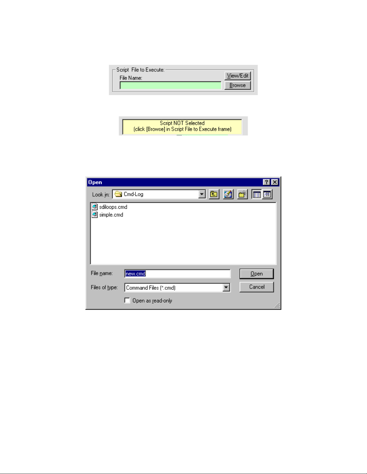
5.1.1 SCRIPT FORM’S COMMAND (SCRIPT) FILE SELECTION FRAME
The first frame of controls is labeled Script File To Execute: and its File Name: text box is initially empty.
The pale yellow status box (in the third frame) will contain an initial prompt message indicating the need to select a script first.
The frame also contains a View/Edit button and a Browse button. Click the Browse button (or double-click the light green adjacent
text box) to open a common Windows
will point to Data Scout Advanced subfolder. If not, navigate to that path (normally C:\YSI\DSAdv\Cmd-Log).
®
Open File Dialog window that will allow you to select a command file. Normally, this dialog
Figure 5.2
YSI Incorporated Data Scout Advanced 64
Page 69

In the example above, there are two existing script (.cmd) files shown in the larger white directory box. Click any file name to
highlight it, and then press the Open button to select it. You can also enter a new script file name (e.g., new.cmd) directly in the File
name: box below the directory box, and then click Open. The new file need not exist. Either way, the dialogue box will close and the
full path name of the file selected (or entered) will appear in the File Name: text box on the form. You have now selected a file name
for Script execution (existing or not).
To avoid using the Browse button in the selection frame, click the light green text box to enter the full path name of any .cmd file that
exists (or not) anywhere on a fixed or removable drive on the PC. If it does not yet exist, enter the full path name of where you want it
to exist.
To create a file, or to view an existing file’s contents or make editing changes to it, click the View/Edit button just above the Browse
button. This will activate the configurable Data Scout Advanced Text Editor. See chapter 2 for information on how to configure a
favorite text editor as the Data Scout Advanced Text Editor.
Once the selected Script file exists (and its name also appears in the light green text box), proceed to the next phase which is the
selection of a Log file name.
5.1.2 SCRIPT FORM’S LOG FILE SELECTION FRAME
The second frame of controls is labeled Log File to Write: and its File Name: text box is initially specified automatically. A default Log
file name is automatically chosen based on the “root” name of the Command file chosen.
This frame also contains a View/Edit button and a Browse button. In fact, using this frame works exactly like the previous frame
described in section 5.1.1. Use the default name provided, enter any other name chosen by navigation methods, or enter its full path
name directly in the light green text box. The only disadvantage of using the automatic name is that if you execute the same script
twice, the Log file for the first script will be overwritten. Therefore, use the Browse button and its dialog window to rename the Log file
or to make its name unique for each command file execution. The user could also use the dialog window (or the Archive function in
main Data Scout Advanced File menu) to copy or move a previous completed Log file to another subfolder, thus a new one will be
created when executing the script.
To not receive a log of executed command responses, uncheck the normally-checked option titled Write Log. This can be useful if
there is a time sensitive script that needs to execute with minimum overhead (e.g., for looking at command timing on an oscilloscope).
5.1.3 SCRIPT FORM’S EXECUTION CONTROL FRAME
Once a Script (.cmd) file and a Log (.log) file have been named in the previous two frames (and the .cmd file actually exists) you are
ready to execute the script using the third frame show below:
Figure 5.3
The above window has five option check boxes, most checked by default. These options will be discussed below. The main status box
(pale yellow above) indicates whether or not a script is ready to execute. The other two (white) status boxes show the progress of the
YSI Incorporated Data Scout Advanced 65
Page 70

script’s execution (they show the latest executed command, and latest received response, respectively). Each has a normally-check
option check box. Uncheck these options if you do not wish these status boxes to be used to indicate the current state of command
execution.
To start executing the Script file click the Execute button. The button will be then be renamed Abort Script to stop it. The main status
box will turn bright yellow and a circular “lamp” (under the Abort Script button) will alternate yellow/gray for each command line
executed.
Another button labeled Skip Cmd will be enabled while the script is being executed. Use it only if you discover (by observing the
Latest Command: text box) that some transducer command or meta-command has “hung” the Script program or if some wait metacommand (timed delay) is taking a bit too long. A small light blue text box will also appear on the form (near the lamp) only when a
wait meta-command is being executed and will indicate as “down-count” of the time (in seconds) still remaining in that delay.
The Skip Cmd. button will only abort the current command’s text line, and force the script to move on to the next text line. This
button may also be occasionally renamed Resume if any pause meta-command is encountered while executing the script. Such a
meta-command simply displays a “prompt” message to the user in the Last Command: status box, and “hangs” the script indefinitely
until the user responds to the message’s instructions.
Once execution begins the Script (.cmd) file will open and its text lines will be counted on a first pass. A second pass of the file will
read all its text lines and store them into a dynamically allocated string array in main memory. The file is then closed while it is being
executed. Next, the Log file is opened (if optioned) as a new text file. This file will record and annotate all actions that need to be
recorded during the execution of the script. For long scripts, the Log file may also grow very large particularly if the script contains
loops.
The first pass of the two-pass script file reading process (called the Pre-Compile phase) will seem essentially instantaneous unless the
file is extremely long. It is necessary to read the file’s lines into memory to allow the commands to be executed randomly due to the
possibility of loop meta-commands being allowed in a script file (see Appendix C for a description of all Script commands and metacommands). The only disadvantage is that the practical length to any script file is ultimately limited by the available “virtual” and
“real” memory space allocated to the Data Scout Advanced application by Windows
®
. If the Pre-Compile phase discovers “looping”
meta-command errors, the script will be self aborted before the Log file is opened. In this case, the main status box turns bright
orange, and a message is displayed there to indicate that no Log file was even written.
If a bad transducer command is encountered in the script during execution that the program recognizes as illegal or unknown, the
script will self-abort if the Stop on Err. option box remains checked. The Log file may then be displayed (by clicking the View/Edit
button in its selection frame) to ascertain the cause. An error message at the end of the Log file will indicate the reason for the abort. If
the script is known to contain such bad commands, then uncheck this option, and re-execute the script. Such errors will be recorded
to the log, but otherwise ignored. This allows the script to continue execution even with errors.
The Annotate Log (checked by default) and Convert Data (unchecked by default)options being selected (checked) cause the maximum
amount of information annotation of each command line and each response line to be added to the Log file automatically during a
script’s execution. Select Convert Data only if you want certain acquired Streams of binary data, or certain command responses with
similar binary data, to be converted into readable numerical numbers. The user might find such extravagance undesirable if it is a
“time critical” sequence of commands in a script, and wish to minimize the overhead of the script program itself thus disabling these
options. For the same reason, the user might wish to prevent the Latest Command: and Latest Response: status boxes being updated
continuously during script execution, in which case the user could also disable the Show Commands and Show Responses options.
Finally, disable the Log file being written entirely to achieve minimum script execution overhead.
After a script’s execution has completed, the bright yellow main status box turns bright green to indicate success. If the script self
aborts this status box turns bright red.
After the script ends normally (or is aborted) the user may return to the second frame and click the View/Edit button, to review the
Log file just generated. To print or save this file, use the functions of the Text Editor window that appears. This editor will (if properly
configured) also allow the user to open and examine the progress of a partially completed Log file currently being written. This can be
very convenient if the script file takes a long time to execute.
5.1.4 SCRIPT AND LOG EXAMPLE
On the following pages you will find the full printouts of an example Script file (named SdiROTest.cmd) followed by its execution Log
file (named SDI-12.log). The script will execute every read-only command of a transducer for the first (#1) or only transducer defined
YSI Incorporated Data Scout Advanced 66
Page 71

in the Transducer Net Map. If more than one transducer is defined on the Transducer Net Map, the Script has a loop that will repeat
for each transducer. In this particular example, however, there was only a single transducer defined thus the loop terminated after one
iteration. The Script file uses many short comment lines (') to separate one command from another making it longer than necessary
but easier to read. The Log file that follows was created when this Script file was executed. See Appendix C if you do not understand
all the commands and meta-commands used in this script.
'Simple Test Script for SDI-12 Transducers (Read-Only Commands)
Set n NumXdcrs
Wait 0
Set x 1
DO LOOP1 n
'
(#x)I
'
(#x)XT+0
Wait PrvRspSec
(#x)
(#x)D0
DO LOOP2
'
(#x)U OPEN
(#x)XM+1
Wait PrvRspSec
(#x)
(#x)D0
(#x)L
(#x)XM+1
Wait PrvRspSec
(#x)
(#x)D0
'
(#x)M
Wait PrvRspSec
(#x)
(#x)D0
'
(#x)M0
Wait PrvRspSec
(#x)
(#x)D0
'
(#x)M1
Wait PrvRspSec
(#x)
(#x)D0
'
(#x)M2
Wait PrvRspSec
(#x)
(#x)D0
'
(#x)M3
Wait PrvRspSec
(#x)
(#x)D0
'
(#x)M4
Wait PrvRspSec
(#x)
YSI Incorporated Data Scout Advanced 67
Page 72

(#x)D0
'
(#x)M5
Wait PrvRspSec
(#x)
(#x)D0
'
(#x)M6
Wait PrvRspSec
(#x)
(#x)D0
'
(#x)C
Wait PrvRspSec
(#x)D0
'
(#x)C0
Wait PrvRspSec
(#x)D0
'
(#x)C1
Wait PrvRspSec
(#x)D0
'
(#x)C2
Wait PrvRspSec
(#x)D0
'
(#x)C3
Wait PrvRspSec
(#x)D0
'
(#x)C4
Wait PrvRspSec
(#x)D0
'
(#x)C5
Wait PrvRspSec
(#x)D0
'
(#x)C6
Wait PrvRspSec
(#x)D0
'
(#x)U OPEN
(#x)XR+0
Wait PrvRspSec
(#x)
(#x)D0
(#x)XR+1
Wait PrvRspSec
(#x)
(#x)D0
(#x)XR+2
Wait PrvRspSec
(#x)
(#x)D0
(#x)XR+3
Wait PrvRspSec
(#x)
YSI Incorporated Data Scout Advanced 68
Page 73

(#x)D0
'
(#x)XR+22
Wait PrvRspSec
(#x)
(#x)D0
(#x)XR+23
Wait PrvRspSec
(#x)
(#x)D0
(#x)L
'
(#x)XT+5
Wait PrvRspSec
(#x)
(#x)D0
'
LOOP2 2
'
(#x)XT+0
Wait PrvRspSec
(#x)
(#x)D0
'
AddTo x 1
LOOP1
Wait 0
When the Script (Command) file above is executed, it generates the following Log file. This Log file example was created when the
Execute Script window had all possible options enabled thus the file is quite long.
-- DSAdv 'Execute Script' Log File, for script: C:\YSI\DSAdv\Cmd-Log\SdiROTest.cmd
-- DSADV has made available the following 1 Transducer:
--- Xducer #1: VS2-012345 (Vintage Tank) Fmw.Ver=1.1 Hdw.Ver=1.0 Range=15 psi D.O.M=021225 CX=1
-- On SDI-12 Network: Com Port=1 Baud Rate=19200
-- Script started on: 07-23-2006 at 14:31:04 Using DSAdv Version: 1.4.8
Lin<0001>: ' Simple Test Script for SDI-12 Xducer #1
Cmd<0002>: Set n NumXdcrs ' Set Variable N to Constant 'Number-of-Xducers' (=1)
Cmd<0003>: Wait 0 ' Relative timestamp (sec.) : 000.001644
Cmd<0004>: Set x 1 ' Set Variable X to value 1
Cmd<0005>: DO LOOP1 ' Begin Loop1 (1 in 1 times)
Lin<0006>: '
Cmd<0007>: (#x) ' Expanded Cmd: 0I (Read Xducer ID String)
Rsp<0007>: _0I!013-YSI---SV2---1.0-012345-1.1__
' Rsp Data(>!): 1=<adrs> 2-n=<idstring='pv-YSI---SV2---hhh-sernum-vvv'>
Lin<0008>: '
Cmd<0009>: (#x)XT+0 ' Expanded Cmd: 0XT+0 (Add Add'l.Averaging Time)+(SR)
Rsp<0009>: _0XT+0!00011__0__ ' Rsp Data(>!): 1=<adrs> 2-4=<rdysec> 5=<numarg>
Cmd<0010>: Wait PrvRspSec ' Waiting for 1 seconds
Rsp<0010>: Wait began at 14:31:05 and ended at 14:31:06
Cmd<0011>: (#x) ' Expanded Cmd: 0 (Read SR=Service Request)
Rsp<0011>: 0__ ' Rsp Data(>!): 1=<adrs> (SR)
Cmd<0012>: (#x)D0 ' Expanded Cmd: 0D0 (Read Data)
Rsp<0012>: _0D0!0+1__ ' Rsp Data(>!): 1=<adrs>+<numsamp>
Cmd<0013>: DO LOOP2 ' Begin Loop2
Lin<0014>: '
Cmd<0015>: (#x)U OPEN ' Expanded Cmd: 0U OPEN (Unlock Xducer)
YSI Incorporated Data Scout Advanced 69
Page 74

Rsp<0015>: _0U OPEN!0__ ' Rsp Data(>!): 1=<adrs>
Cmd<0016>: (#x)XM+1 ' Expanded Cmd: 0XM+1 (Measure Raw Temp./Press.Volts)+(SR)
Rsp<0016>: _0XM+1!0005 ' Rsp Data(>!): 1=<adrs> 2-4=<rdysec> 5=<numarg>
Cmd<0017>: Wait PrvRspSec ' Waiting for 5 seconds
Rsp<0017>: Wait began at 14:31:06 and ended at 14:31:11
Cmd<0018>: (#x) ' Expanded Cmd: 0 (Read SR=Service Request)
Rsp<0018>: 0__ ' Rsp Data(>!): 1=<adrs> (SR)
Cmd<0019>: (#x)D0 ' Expanded Cmd: 0D0 (Read Data)
Rsp<0019>: _0D0!0+0.525487+0.081228__ ' Rsp Data(>!): 1=<adrs>+<tempvolts>+<pressvolts>
Cmd<0020>: (#x)L ' Expanded Cmd: 0L (Lock Xducer)
Rsp<0020>: _0L!0__ ' Rsp Data(>!): 1=<adrs>
Cmd<0021>: (#x)XM+1 ' Expanded Cmd: 0XM+1 (Measure Raw Temp./Press.Volts)+(SR)
Rsp<0021>: _0XM+1!0__0__ ' Rsp Data(>!): 1=<adrs> 2-4=<rdysec> 5=<numarg>
Cmd<0022>: Wait PrvRspSec ' Relative timestamp (sec.) : 008.494562
Cmd<0023>: (#x) ' Expanded Cmd: 0 (Read SR=Service Request)
Rsp<0023>: 0__ ' Rsp Data(>!): 1=<adrs> (SR)
Cmd<0024>: (#x)D0 ' Expanded Cmd: 0D0 (Read Data)
Rsp<0024>: _0D0!0__ ' Rsp Data(>!): 1=<adrs>+<tempvolts>+<pressvolts>
Lin<0025>: '
Cmd<0026>: (#x)M ' Expanded Cmd: 0M (Measure Pressure (units)+(SR)
Rsp<0026>: _0M!00022__ ' Rsp Data(>!): 1=<adrs> 2-4=<rdysec> 5=<numarg>
Cmd<0027>: Wait PrvRspSec ' Waiting for 2 seconds
Rsp<0027>: Wait began at 14:31:13 and ended at 14:31:15
Cmd<0028>: (#x) ' Expanded Cmd: 0 (Read SR=Service Request)
Rsp<0028>: 0__ ' Rsp Data(>!): 1=<adrs> (SR)
Cmd<0029>: (#x)D0 ' Expanded Cmd: 0D0 (Read Data)
Rsp<0029>: _0D0!0-0.03998+11__ ' Rsp Data(>!): 1=<adrs>+<press>+<unitx>
Lin<0030>: '
Cmd<0031>: (#x)M0 ' Expanded Cmd: 0M0 (Meas. Pressure (units))+(SR)
Rsp<0031>: _0M0!00022__ ' Rsp Data(>!): 1=<adrs> 2-4=<rdysec> 5=<numarg>
Cmd<0032>: Wait PrvRspSec ' Waiting for 2 seconds
Rsp<0032>: Wait began at 14:31:15 and ended at 14:31:17
Cmd<0033>: (#x) ' Expanded Cmd: 0 (Read SR=Service Request)
Rsp<0033>: 0__ ' Rsp Data(>!): 1=<adrs> (SR)
Cmd<0034>: (#x)D0 ' Expanded Cmd: 0D0 (Read Data)
Rsp<0034>: _0D0!0-0.04158+11__ ' Rsp Data(>!): 1=<adrs>+<press>+<unitx>
(unitx:0=ftH20,1=psi,2=kPa,3=cmH20,4=mH20,5=mmH20,9=userunits)
Lin<0035>: '
Cmd<0036>: (#x)M1 ' Expanded Cmd: 0M1 (Meas. Fac. Press. (psi))+(SR)
Rsp<0036>: _0M1!00021__ ' Rsp Data(>!): 1=<adrs> 2-4=<rdysec> 5=<numarg>
Cmd<0037>: Wait PrvRspSec ' Waiting for 2 seconds
Rsp<0037>: Wait began at 14:31:18 and ended at 14:31:20
Cmd<0038>: (#x) ' Expanded Cmd: 0 (Read SR=Service Request)
Rsp<0038>: 0__ ' Rsp Data(>!): 1=<adrs> (SR)
Cmd<0039>: (#x)D0 ' Expanded Cmd: 0D0 (Read Data)
Rsp<0039>: _0D0!0-0.00612__ ' Rsp Data(>!): 1=<adrs>+<press(psi)>
Lin<0040>: '
Cmd<0041>: (#x)M2 ' Expanded Cmd: 0M2 (Meas. Temperature)+(SR)
Rsp<0041>: _0M2!00022__ ' Rsp Data(>!): 1=<adrs> 2-4=<rdysec> 5=<numarg>
Cmd<0042>: Wait PrvRspSec ' Waiting for 2 seconds
Rsp<0042>: Wait began at 14:31:21 and ended at 14:31:23
Cmd<0043>: (#x) ' Expanded Cmd: 0 (Read SR=Service Request)
Rsp<0043>: 0__ ' Rsp Data(>!): 1=<adrs> (SR)
Cmd<0044>: (#x)D0 ' Expanded Cmd: 0D0 (Read Data)
Rsp<0044>: _0D0!0+23.000+0__ ' Rsp Data(>!): 1=<adrs>+<temp>+<unitx>(unitx:0=degC,1=degF)
Lin<0045>: '
Cmd<0046>: (#x)M3 ' Expanded Cmd: 0M3 (Meas. User Coeffs.)+(SR)
Rsp<0046>: _0M3!00013__ ' Rsp Data(>!): 1=<adrs> 2-4=<rdysec> 5=<numarg>
Cmd<0047>: Wait PrvRspSec ' Waiting for 1 seconds
Rsp<0047>: Wait began at 14:31:23 and ended at 14:31:24
YSI Incorporated Data Scout Advanced 70
Page 75

Cmd<0048>: (#x) ' Expanded Cmd: 0 (Read SR=Service Request)
Rsp<0048>: 0__ ' Rsp Data(>!): 1=<adrs> (SR)
Cmd<0049>: (#x)D0 ' Expanded Cmd: 0D0 (Read Data)
Rsp<0049>: _0D0!0+1.000000+0.000000-0.033854__
' Rsp Data(>!): 1=<adrs>+<usrslp>+<usrofst(psi)>+<fldofst(psi)>
Lin<0050>: '
Cmd<0051>: (#x)M4 ' Expanded Cmd: 0M4 (Meas. Cal. Coeffs.)+(SR)
Rsp<0051>: _0M4!00012__ ' Rsp Data(>!): 1=<adrs> 2-4=<rdysec> 5=<numarg>
Cmd<0052>: Wait PrvRspSec ' Waiting for 1 seconds
Rsp<0052>: Wait began at 14:31:25 and ended at 14:31:26
Cmd<0053>: (#x) ' Expanded Cmd: 0 (Read SR=Service Request)
Rsp<0053>: 0__ ' Rsp Data(>!): 1=<adrs> (SR)
Cmd<0054>: (#x)D0 ' Expanded Cmd: 0D0 (Read Data)
Rsp<0054>: _0D0!0+1.000000+0.000000__ ' Rsp Data(>!): 1=<adrs>+<calslp>+<calofst(psi)>
Lin<0055>: '
Cmd<0056>: (#x)M5 ' Expanded Cmd: 0M5 (Meas..PCB Temperature)+(SR)
Rsp<0056>: _0M5!00022__ ' Rsp Data(>!): 1=<adrs> 2-4=<rdysec> 5=<numarg>
Cmd<0057>: Wait PrvRspSec ' Waiting for 2 seconds
Rsp<0057>: Wait began at 14:31:26 and ended at 14:31:28
Cmd<0058>: (#x) ' Expanded Cmd: 0 (Read SR=Service Request)
Rsp<0058>: 0__ ' Rsp Data(>!): 1=<adrs> (SR)
Cmd<0059>: (#x)D0 ' Expanded Cmd: 0D0 (Read Data)
Rsp<0059>: _0D0!0+23.661+0__ ' Rsp Data(>!): 1=<adrs>+<temp>+<unitx>(unitx:0=degC,1=degF)
Lin<0060>: '
Cmd<0061>: (#x)M6 ' Expanded Cmd: 0M6 (Meas. Excitation Voltage)+(SR)
Rsp<0061>: _0M6!00021__ ' Rsp Data(>!): 1=<adrs> 2-4=<rdysec> 5=<numarg>
Cmd<0062>: Wait PrvRspSec ' Waiting for 2 seconds
Rsp<0062>: Wait began at 14:31:29 and ended at 14:31:31
Cmd<0063>: (#x) ' Expanded Cmd: 0 (Read SR=Service Request)
Rsp<0063>: 0__ ' Rsp Data(>!): 1=<adrs> (SR)
Cmd<0064>: (#x)D0 ' Expanded Cmd: 0D0 (Read Data)
Rsp<0064>: _0D0!0+12.0__ ' Rsp Data(>!): 1=<adrs>+<volts>
Lin<0065>: '
Cmd<0066>: (#x)C ' Expanded Cmd: 0C (Measure Pressure (units))
Rsp<0066>: _0C!000202__ ' Rsp Data(>!): 1=<adrs> 2-4=<rdysec> 5-6=<numarg>
Cmd<0067>: Wait PrvRspSec ' Waiting for 2 seconds
Rsp<0067>: Wait began at 14:31:32 and ended at 14:31:34
Cmd<0068>: (#x)D0 ' Expanded Cmd: 0D0 (Read Data)
Rsp<0068>: _0D0!0-0.04032+11__ ' Rsp Data(>!): 1=<adrs>+<press>+<unitx>
Lin<0069>: '
Cmd<0070>: (#x)C0 ' Expanded Cmd: 0C0 (Meas. Pressure (units))
Rsp<0070>: _0C0!000202__ ' Rsp Data(>!): 1=<adrs> 2-4=<rdysec> 5-6=<numarg>
Cmd<0071>: Wait PrvRspSec ' Waiting for 2 seconds
Rsp<0071>: Wait began at 14:31:34 and ended at 14:31:36
Cmd<0072>: (#x)D0 ' Expanded Cmd: 0D0 (Read Data)
Rsp<0072>: _0D0!0-0.04330+11__ ' Rsp Data(>!): 1=<adrs>+<press>+<unitx>
(unitx:0=ftH20,1=psi,2=kPa,3=cmH20,4=mH20,5=mmH20,9=userunits)
Lin<0073>: '
Cmd<0074>: (#x)C1 ' Expanded Cmd: 0C1 (Meas. Fac. Press. (psi))
Rsp<0074>: _0C1!000201__ ' Rsp Data(>!): 1=<adrs> 2-4=<rdysec> 5-6=<numarg>
Cmd<0075>: Wait PrvRspSec ' Waiting for 2 seconds
Rsp<0075>: Wait began at 14:31:37 and ended at 14:31:39
Cmd<0076>: (#x)D0 ' Expanded Cmd: 0D0 (Read Data)
Rsp<0076>: _0D0!0-0.01099__ ' Rsp Data(>!): 1=<adrs>+<press(psi)>
Lin<0077>: '
Cmd<0078>: (#x)C2 ' Expanded Cmd: 0C2 (Meas. Temperature)
Rsp<0078>: _0C2!000202__ ' Rsp Data(>!): 1=<adrs> 2-4=<rdysec> 5-6=<numarg>
Cmd<0079>: Wait PrvRspSec ' Waiting for 2 seconds
Rsp<0079>: Wait began at 14:31:39 and ended at 14:31:41
Cmd<0080>: (#x)D0 ' Expanded Cmd: 0D0 (Read Data)
YSI Incorporated Data Scout Advanced 71
Page 76

Rsp<0080>: _0D0!0+23.000+0__ ' Rsp Data(>!): 1=<adrs>+<temp>+<unitx>(unitx:0=degC,1=degF)
Lin<0081>: '
Cmd<0082>: (#x)C3 ' Expanded Cmd: 0C3 (Meas. User Coeffs.)
Rsp<0082>: _0C3!000103__ ' Rsp Data(>!): 1=<adrs> 2-4=<rdysec> 5-6=<numarg>
Cmd<0083>: Wait PrvRspSec ' Waiting for 1 seconds
Rsp<0083>: Wait began at 14:31:42 and ended at 14:31:43
Cmd<0084>: (#x)D0 ' Expanded Cmd: 0D0 (Read Data)
Rsp<0084>: _0D0!0+1.000000+0.000000-0.033854__
' Rsp Data(>!): 1=<adrs>+<usrslp>+<usrofst(psi)>+<fldofst(psi)>
Lin<0085>: '
Cmd<0086>: (#x)C4 ' Expanded Cmd: 0C4 (Meas. Cal. Coeffs.)
Rsp<0086>: _0C4!000102__ ' Rsp Data(>!): 1=<adrs> 2-4=<rdysec> 5-6=<numarg>
Cmd<0087>: Wait PrvRspSec ' Waiting for 1 seconds
Rsp<0087>: Wait began at 14:31:44 and ended at 14:31:45
Cmd<0088>: (#x)D0 ' Expanded Cmd: 0D0 (Read Data)
Rsp<0088>: _0D0!0+1.000000+0.000000__ ' Rsp Data(>!): 1=<adrs>+<calslp>+<calofst(psi)>
Lin<0089>: '
Cmd<0090>: (#x)C5 ' Expanded Cmd: 0C5 (Meas..PCB Temperature)
Rsp<0090>: _0C5!000202__ ' Rsp Data(>!): 1=<adrs> 2-4=<rdysec> 5-6=<numarg>
Cmd<0091>: Wait PrvRspSec ' Waiting for 2 seconds
Rsp<0091>: Wait began at 14:31:45 and ended at 14:31:47
Cmd<0092>: (#x)D0 ' Expanded Cmd: 0D0 (Read Data)
Rsp<0092>: _0D0!0+23.740+0__ ' Rsp Data(>!): 1=<adrs>+<temp>+<unitx>(unitx:0=degC,1=degF)
Lin<0093>: '
Cmd<0094>: (#x)C6 ' Expanded Cmd: 0C6 (Meas. Excitation Voltage)
Rsp<0094>: _0C6!000201__ ' Rsp Data(>!): 1=<adrs> 2-4=<rdysec> 5-6=<numarg>
Cmd<0095>: Wait PrvRspSec ' Waiting for 2 seconds
Rsp<0095>: Wait began at 14:31:48 and ended at 14:31:50
Cmd<0096>: (#x)D0 ' Expanded Cmd: 0D0 (Read Data)
Rsp<0096>: _0D0!0+12.0__ ' Rsp Data(>!): 1=<adrs>+<volts>
Lin<0097>: '
Cmd<0098>: (#x)U OPEN ' Expanded Cmd: 0U OPEN (Unlock Xducer)
Rsp<0098>: _0U OPEN!0__ ' Rsp Data(>!): 1=<adrs>
Cmd<0099>: (#x)XR+0 ' Expanded Cmd: 0XR+0 (Read Coefficient)+(SR)
Rsp<0099>: _0XR+0!00012__0__ ' Rsp Data(>!): 1=<adrs> 2-4=<rdysec> 5=<numarg>
Cmd<0100>: Wait PrvRspSec ' Waiting for 1 seconds
Rsp<0100>: Wait began at 14:31:51 and ended at 14:31:52
Cmd<0101>: (#x) ' Expanded Cmd: 0 (Read SR=Service Request)
Rsp<0101>: 0__ ' Rsp Data(>!): 1=<adrs> (SR)
Cmd<0102>: (#x)D0 ' Expanded Cmd: 0D0 (Read Data)
Rsp<0102>: _0D0!0__ ' Rsp Data(>!): 1=<adrs>+<coefx>+<coefval>
Cmd<0103>: (#x)XR+1 ' Expanded Cmd: 0XR+1 (Read Coefficient)+(SR)
Rsp<0103>: _0XR+1!00012__0__ ' Rsp Data(>!): 1=<adrs> 2-4=<rdysec> 5=<numarg>
Cmd<0104>: Wait PrvRspSec ' Waiting for 1 seconds
Rsp<0104>: Wait began at 14:31:52 and ended at 14:31:53
Cmd<0105>: (#x) ' Expanded Cmd: 0 (Read SR=Service Request)
Rsp<0105>: 0__ ' Rsp Data(>!): 1=<adrs> (SR)
Cmd<0106>: (#x)D0 ' Expanded Cmd: 0D0 (Read Data)
Rsp<0106>: _0D0!0__ ' Rsp Data(>!): 1=<adrs>+<coefx>+<coefval>
Cmd<0107>: (#x)XR+2 ' Expanded Cmd: 0XR+2 (Read Coefficient)+(SR)
Rsp<0107>: _0XR+2!00012__ ' Rsp Data(>!): 1=<adrs> 2-4=<rdysec> 5=<numarg>
Cmd<0108>: Wait PrvRspSec ' Waiting for 1 seconds
Rsp<0108>: Wait began at 14:31:54 and ended at 14:31:55
Cmd<0109>: (#x) ' Expanded Cmd: 0 (Read SR=Service Request)
Rsp<0109>: 0__ ' Rsp Data(>!): 1=<adrs> (SR)
Cmd<0110>: (#x)D0 ' Expanded Cmd: 0D0 (Read Data)
Rsp<0110>: _0D0!0+05-257012.0__ ' Rsp Data(>!): 1=<adrs>+<coefx>+<coefval>
Cmd<0111>: (#x)XR+3 ' Expanded Cmd: 0XR+3 (Read Coefficient)+(SR)
Rsp<0111>: _0XR+3!00012__ ' Rsp Data(>!): 1=<adrs> 2-4=<rdysec> 5=<numarg>
Cmd<0112>: Wait PrvRspSec ' Waiting for 1 seconds
YSI Incorporated Data Scout Advanced 72
Page 77

Rsp<0112>: Wait began at 14:31:55 and ended at 14:31:56
Cmd<0113>: (#x) ' Expanded Cmd: 0 (Read SR=Service Request)
Rsp<0113>: 0__ ' Rsp Data(>!): 1=<adrs> (SR)
Cmd<0114>: (#x)D0 ' Expanded Cmd: 0D0 (Read Data)
Rsp<0114>: _0D0!0+15+16777216__ ' Rsp Data(>!): 1=<adrs>+<coefx>+<coefval>
Lin<0115>: '
Cmd<0116>: (#x)XR+22 ' Expanded Cmd: 0XR+22 (Read Coefficient)+(SR)
Rsp<0116>: _0XR+22!00012__ ' Rsp Data(>!): 1=<adrs> 2-4=<rdysec> 5=<numarg>
Cmd<0117>: Wait PrvRspSec ' Waiting for 1 seconds
Rsp<0117>: Wait began at 14:31:57 and ended at 14:31:58
Cmd<0118>: (#x) ' Expanded Cmd: 0 (Read SR=Service Request)
Rsp<0118>: 0__ ' Rsp Data(>!): 1=<adrs> (SR)
Cmd<0119>: (#x)D0 ' Expanded Cmd: 0D0 (Read Data)
Rsp<0119>: _0D0!0+22+195.9367__ ' Rsp Data(>!): 1=<adrs>+<coefx>+<coefval>
Cmd<0120>: (#x)XR+23 ' Expanded Cmd: 0XR+23 (Read Coefficient)+(SR)
Rsp<0120>: _0XR+23!00012__0__ ' Rsp Data(>!): 1=<adrs> 2-4=<rdysec> 5=<numarg>
Cmd<0121>: Wait PrvRspSec ' Waiting for 1 seconds
Rsp<0121>: Wait began at 14:31:59 and ended at 14:32:00
Cmd<0122>: (#x) ' Expanded Cmd: 0 (Read SR=Service Request)
Rsp<0122>: 0__ ' Rsp Data(>!): 1=<adrs> (SR)
Cmd<0123>: (#x)D0 ' Expanded Cmd: 0D0 (Read Data)
Rsp<0123>: _0D0!0__ ' Rsp Data(>!): 1=<adrs>+<coefx>+<coefval>
Cmd<0124>: (#x)L ' Expanded Cmd: 0L (Lock Xducer)
Rsp<0124>: _0L!0__ ' Rsp Data(>!): 1=<adrs>
Lin<0125>: '
Cmd<0126>: (#x)XT+5 ' Expanded Cmd: 0XT+5 (Add Add'l.Averaging Time)+(SR)
Rsp<0126>: _0XT+5!00011__0__ ' Rsp Data(>!): 1=<adrs> 2-4=<rdysec> 5=<numarg>
Cmd<0127>: Wait PrvRspSec ' Waiting for 1 seconds
Rsp<0127>: Wait began at 14:32:01 and ended at 14:32:02
Cmd<0128>: (#x) ' Expanded Cmd: 0 (Read SR=Service Request)
Rsp<0128>: 0__ ' Rsp Data(>!): 1=<adrs> (SR)
Cmd<0129>: (#x)D0 ' Expanded Cmd: 0D0 (Read Data)
Rsp<0129>: _0D0!0+39__ ' Rsp Data(>!): 1=<adrs>+<numsamp>
Lin<0130>: '
Cmd<0131>: LOOP2 2 ' Repeat Loop2 (1 of 2 times)
Cmd<0132>: DO LOOP2 ' Begin Loop2
Lin<0133>: '
Cmd<0134>: (#x)U OPEN ' Expanded Cmd: 0U OPEN (Unlock Xducer)
Rsp<0134>: _0U OPEN!0__ ' Rsp Data(>!): 1=<adrs>
Cmd<0135>: (#x)XM+1 ' Expanded Cmd: 0XM+1 (Measure Raw Temp./Press.Volts)+(SR)
Rsp<0135>: _0XM+1!00052__ ' Rsp Data(>!): 1=<adrs> 2-4=<rdysec> 5=<numarg>
Cmd<0136>: Wait PrvRspSec ' Waiting for 5 seconds
Rsp<0136>: Wait began at 14:32:02 and ended at 14:32:07
Cmd<0137>: (#x) ' Expanded Cmd: 0 (Read SR=Service Request)
Rsp<0137>: 0__ ' Rsp Data(>!): 1=<adrs> (SR)
Cmd<0138>: (#x)D0 ' Expanded Cmd: 0D0 (Read Data)
Rsp<0138>: _0D0!0+0.525480+0.081230__ ' Rsp Data(>!): 1=<adrs>+<tempvolts>+<pressvolts>
Cmd<0139>: (#x)L ' Expanded Cmd: 0L (Lock Xducer)
Rsp<0139>: _0L!0__ ' Rsp Data(>!): 1=<adrs>
Cmd<0140>: (#x)XM+1 ' Expanded Cmd: 0XM+1 (Measure Raw Temp./Press.Volts)+(SR)
Rsp<0140>: _0XM+1!0__0__ ' Rsp Data(>!): 1=<adrs> 2-4=<rdysec> 5=<numarg>
Cmd<0141>: Wait PrvRspSec ' Relative timestamp (sec.) : 064.452654
Cmd<0142>: (#x) ' Expanded Cmd: 0 (Read SR=Service Request)
Rsp<0142>: 0__ ' Rsp Data(>!): 1=<adrs> (SR)
Cmd<0143>: (#x)D0 ' Expanded Cmd: 0D0 (Read Data)
Rsp<0143>: _0D0!0__ ' Rsp Data(>!): 1=<adrs>+<tempvolts>+<pressvolts>
Lin<0144>: '
Cmd<0145>: (#x)M ' Expanded Cmd: 0M (Measure Pressure (units)+(SR)
Rsp<0145>: _0M!00062__ ' Rsp Data(>!): 1=<adrs> 2-4=<rdysec> 5=<numarg>
Cmd<0146>: Wait PrvRspSec ' Waiting for 6 seconds
YSI Incorporated Data Scout Advanced 73
Page 78

Rsp<0146>: Wait began at 14:32:09 and ended at 14:32:15
Cmd<0147>: (#x) ' Expanded Cmd: 0 (Read SR=Service Request)
Rsp<0147>: 0__ ' Rsp Data(>!): 1=<adrs> (SR)
Cmd<0148>: (#x)D0 ' Expanded Cmd: 0D0 (Read Data)
Rsp<0148>: _0D0!0-0.04439+11__ ' Rsp Data(>!): 1=<adrs>+<press>+<unitx>
Lin<0149>: '
Cmd<0150>: (#x)M0 ' Expanded Cmd: 0M0 (Meas. Pressure (units))+(SR)
Rsp<0150>: _0M0!00062__ ' Rsp Data(>!): 1=<adrs> 2-4=<rdysec> 5=<numarg>
Cmd<0151>: Wait PrvRspSec ' Waiting for 6 seconds
Rsp<0151>: Wait began at 14:32:15 and ended at 14:32:21
Cmd<0152>: (#x) ' Expanded Cmd: 0 (Read SR=Service Request)
Rsp<0152>: 0__ ' Rsp Data(>!): 1=<adrs> (SR)
Cmd<0153>: (#x)D0 ' Expanded Cmd: 0D0 (Read Data)
Rsp<0153>: _0D0!0-0.04166+11__ ' Rsp Data(>!): 1=<adrs>+<press>+<unitx>
(unitx:0=ftH20,1=psi,2=kPa,3=cmH20,4=mH20,5=mmH20,9=userunits)
Lin<0154>: '
Cmd<0155>: (#x)M1 ' Expanded Cmd: 0M1 (Meas. Fac. Press. (psi))+(SR)
Rsp<0155>: _0M1!00061__ ' Rsp Data(>!): 1=<adrs> 2-4=<rdysec> 5=<numarg>
Cmd<0156>: Wait PrvRspSec ' Waiting for 6 seconds
Rsp<0156>: Wait began at 14:32:22 and ended at 14:32:28
Cmd<0157>: (#x) ' Expanded Cmd: 0 (Read SR=Service Request)
Rsp<0157>: 0__ ' Rsp Data(>!): 1=<adrs> (SR)
Cmd<0158>: (#x)D0 ' Expanded Cmd: 0D0 (Read Data)
Rsp<0158>: _0D0!0-0.00907__ ' Rsp Data(>!): 1=<adrs>+<press(psi)>
Lin<0159>: '
Cmd<0160>: (#x)M2 ' Expanded Cmd: 0M2 (Meas. Temperature)+(SR)
Rsp<0160>: _0M2!00062__ ' Rsp Data(>!): 1=<adrs> 2-4=<rdysec> 5=<numarg>
Cmd<0161>: Wait PrvRspSec ' Waiting for 6 seconds
Rsp<0161>: Wait began at 14:32:28 and ended at 14:32:34
Cmd<0162>: (#x) ' Expanded Cmd: 0 (Read SR=Service Request)
Rsp<0162>: 0__ ' Rsp Data(>!): 1=<adrs> (SR)
Cmd<0163>: (#x)D0 ' Expanded Cmd: 0D0 (Read Data)
Rsp<0163>: _0D0!0+23.000+0__ ' Rsp Data(>!): 1=<adrs>+<temp>+<unitx>(unitx:0=degC,1=degF)
Lin<0164>: '
Cmd<0165>: (#x)M3 ' Expanded Cmd: 0M3 (Meas. User Coeffs.)+(SR)
Rsp<0165>: _0M3!00013__ ' Rsp Data(>!): 1=<adrs> 2-4=<rdysec> 5=<numarg>
Cmd<0166>: Wait PrvRspSec ' Waiting for 1 seconds
Rsp<0166>: Wait began at 14:32:35 and ended at 14:32:36
Cmd<0167>: (#x) ' Expanded Cmd: 0 (Read SR=Service Request)
Rsp<0167>: 0__ ' Rsp Data(>!): 1=<adrs> (SR)
Cmd<0168>: (#x)D0 ' Expanded Cmd: 0D0 (Read Data)
Rsp<0168>: _0D0!0+1.000000+0.000000-0.033854__
' Rsp Data(>!): 1=<adrs>+<usrslp>+<usrofst(psi)>+<fldofst(psi)>
Lin<0169>: '
Cmd<0170>: (#x)M4 ' Expanded Cmd: 0M4 (Meas. Cal. Coeffs.)+(SR)
Rsp<0170>: _0M4!00012__ ' Rsp Data(>!): 1=<adrs> 2-4=<rdysec> 5=<numarg>
Cmd<0171>: Wait PrvRspSec ' Waiting for 1 seconds
Rsp<0171>: Wait began at 14:32:37 and ended at 14:32:38
Cmd<0172>: (#x) ' Expanded Cmd: 0 (Read SR=Service Request)
Rsp<0172>: 0__ ' Rsp Data(>!): 1=<adrs> (SR)
Cmd<0173>: (#x)D0 ' Expanded Cmd: 0D0 (Read Data)
Rsp<0173>: _0D0!0+1.000000+0.000000__ ' Rsp Data(>!): 1=<adrs>+<calslp>+<calofst(psi)>
Lin<0174>: '
Cmd<0175>: (#x)M5 ' Expanded Cmd: 0M5 (Meas..PCB Temperature)+(SR)
Rsp<0175>: _0M5!00022__ ' Rsp Data(>!): 1=<adrs> 2-4=<rdysec> 5=<numarg>
Cmd<0176>: Wait PrvRspSec ' Waiting for 2 seconds
Rsp<0176>: Wait began at 14:32:38 and ended at 14:32:40
Cmd<0177>: (#x) ' Expanded Cmd: 0 (Read SR=Service Request)
Rsp<0177>: 0__ ' Rsp Data(>!): 1=<adrs> (SR)
Cmd<0178>: (#x)D0 ' Expanded Cmd: 0D0 (Read Data)
YSI Incorporated Data Scout Advanced 74
Page 79

Rsp<0178>: _0D0!0+23.921+0__ ' Rsp Data(>!): 1=<adrs>+<temp>+<unitx>(unitx:0=degC,1=degF)
Lin<0179>: '
Cmd<0180>: (#x)M6 ' Expanded Cmd: 0M6 (Meas. Excitation Voltage)+(SR)
Rsp<0180>: _0M6!00021__ ' Rsp Data(>!): 1=<adrs> 2-4=<rdysec> 5=<numarg>
Cmd<0181>: Wait PrvRspSec ' Waiting for 2 seconds
Rsp<0181>: Wait began at 14:32:41 and ended at 14:32:43
Cmd<0182>: (#x) ' Expanded Cmd: 0 (Read SR=Service Request)
Rsp<0182>: 0__ ' Rsp Data(>!): 1=<adrs> (SR)
Cmd<0183>: (#x)D0 ' Expanded Cmd: 0D0 (Read Data)
Rsp<0183>: _0D0!0+12.0__ ' Rsp Data(>!): 1=<adrs>+<volts>
Lin<0184>: '
Cmd<0185>: (#x)C ' Expanded Cmd: 0C (Measure Pressure (units))
Rsp<0185>: _0C!000602__ ' Rsp Data(>!): 1=<adrs> 2-4=<rdysec> 5-6=<numarg>
Cmd<0186>: Wait PrvRspSec ' Waiting for 6 seconds
Rsp<0186>: Wait began at 14:32:44 and ended at 14:32:50
Cmd<0187>: (#x)D0 ' Expanded Cmd: 0D0 (Read Data)
Rsp<0187>: _0D0!0-0.03895+11__ ' Rsp Data(>!): 1=<adrs>+<press>+<unitx>
Lin<0188>: '
Cmd<0189>: (#x)C0 ' Expanded Cmd: 0C0 (Meas. Pressure (units))
Rsp<0189>: _0C0!000602__ ' Rsp Data(>!): 1=<adrs> 2-4=<rdysec> 5-6=<numarg>
Cmd<0190>: Wait PrvRspSec ' Waiting for 6 seconds
Rsp<0190>: Wait began at 14:32:50 and ended at 14:32:56
Cmd<0191>: (#x)D0 ' Expanded Cmd: 0D0 (Read Data)
Rsp<0191>: _0D0!0-0.03885+11__ ' Rsp Data(>!): 1=<adrs>+<press>+<unitx>
(unitx:0=ftH20,1=psi,2=kPa,3=cmH20,4=mH20,5=mmH20,9=userunits)
Lin<0192>: '
Cmd<0193>: (#x)C1 ' Expanded Cmd: 0C1 (Meas. Fac. Press. (psi))
Rsp<0193>: _0C1!000601__ ' Rsp Data(>!): 1=<adrs> 2-4=<rdysec> 5-6=<numarg>
Cmd<0194>: Wait PrvRspSec ' Waiting for 6 seconds
Rsp<0194>: Wait began at 14:32:57 and ended at 14:33:03
Cmd<0195>: (#x)D0 ' Expanded Cmd: 0D0 (Read Data)
Rsp<0195>: _0D0!0-0.01573__ ' Rsp Data(>!): 1=<adrs>+<press(psi)>
Lin<0196>: '
Cmd<0197>: (#x)C2 ' Expanded Cmd: 0C2 (Meas. Temperature)
Rsp<0197>: _0C2!000602__ ' Rsp Data(>!): 1=<adrs> 2-4=<rdysec> 5-6=<numarg>
Cmd<0198>: Wait PrvRspSec ' Waiting for 6 seconds
Rsp<0198>: Wait began at 14:33:03 and ended at 14:33:09
Cmd<0199>: (#x)D0 ' Expanded Cmd: 0D0 (Read Data)
Rsp<0199>: _0D0!0+23.000+0__ ' Rsp Data(>!): 1=<adrs>+<temp>+<unitx>(unitx:0=degC,1=degF)
Lin<0200>: '
Cmd<0201>: (#x)C3 ' Expanded Cmd: 0C3 (Meas. User Coeffs.)
Rsp<0201>: _0C3!000103__ ' Rsp Data(>!): 1=<adrs> 2-4=<rdysec> 5-6=<numarg>
Cmd<0202>: Wait PrvRspSec ' Waiting for 1 seconds
Rsp<0202>: Wait began at 14:33:10 and ended at 14:33:11
Cmd<0203>: (#x)D0 ' Expanded Cmd: 0D0 (Read Data)
Rsp<0203>: _0D0!0+1.000000+0.000000-0.033854__
' Rsp Data(>!): 1=<adrs>+<usrslp>+<usrofst(psi)>+<fldofst(psi)>
Lin<0204>: '
Cmd<0205>: (#x)C4 ' Expanded Cmd: 0C4 (Meas. Cal. Coeffs.)
Rsp<0205>: _0C4!000102__ ' Rsp Data(>!): 1=<adrs> 2-4=<rdysec> 5-6=<numarg>
Cmd<0206>: Wait PrvRspSec ' Waiting for 1 seconds
Rsp<0206>: Wait began at 14:33:12 and ended at 14:33:13
Cmd<0207>: (#x)D0 ' Expanded Cmd: 0D0 (Read Data)
Rsp<0207>: _0D0!0+1.000000+0.000000__ ' Rsp Data(>!): 1=<adrs>+<calslp>+<calofst(psi)>
Lin<0208>: '
Cmd<0209>: (#x)C5 ' Expanded Cmd: 0C5 (Meas..PCB Temperature)
Rsp<0209>: _0C5!000202__ ' Rsp Data(>!): 1=<adrs> 2-4=<rdysec> 5-6=<numarg>
Cmd<0210>: Wait PrvRspSec ' Waiting for 2 seconds
Rsp<0210>: Wait began at 14:33:13 and ended at 14:33:15
Cmd<0211>: (#x)D0 ' Expanded Cmd: 0D0 (Read Data)
YSI Incorporated Data Scout Advanced 75
Page 80

Rsp<0211>: _0D0!0+24.085+0__ ' Rsp Data(>!): 1=<adrs>+<temp>+<unitx>(unitx:0=degC,1=degF)
Lin<0212>: '
Cmd<0213>: (#x)C6 ' Expanded Cmd: 0C6 (Meas. Excitation Voltage)
Rsp<0213>: _0C6!000201__ ' Rsp Data(>!): 1=<adrs> 2-4=<rdysec> 5-6=<numarg>
Cmd<0214>: Wait PrvRspSec ' Waiting for 2 seconds
Rsp<0214>: Wait began at 14:33:16 and ended at 14:33:18
Cmd<0215>: (#x)D0 ' Expanded Cmd: 0D0 (Read Data)
Rsp<0215>: _0D0!0+12.0__ ' Rsp Data(>!): 1=<adrs>+<volts>
Lin<0216>: '
Cmd<0217>: (#x)U OPEN ' Expanded Cmd: 0U OPEN (Unlock Xducer)
Rsp<0217>: _0U OPEN!0__ ' Rsp Data(>!): 1=<adrs>
Cmd<0218>: (#x)XR+0 ' Expanded Cmd: 0XR+0 (Read Coefficient)+(SR)
Rsp<0218>: _0XR+0!00012__0__ ' Rsp Data(>!): 1=<adrs> 2-4=<rdysec> 5=<numarg>
Cmd<0219>: Wait PrvRspSec ' Waiting for 1 seconds
Rsp<0219>: Wait began at 14:33:19 and ended at 14:33:20
Cmd<0220>: (#x) ' Expanded Cmd: 0 (Read SR=Service Request)
Rsp<0220>: 0__ ' Rsp Data(>!): 1=<adrs> (SR)
Cmd<0221>: (#x)D0 ' Expanded Cmd: 0D0 (Read Data)
Rsp<0221>: _0D0!0__ ' Rsp Data(>!): 1=<adrs>+<coefx>+<coefval>
Cmd<0222>: (#x)XR+1 ' Expanded Cmd: 0XR+1 (Read Coefficient)+(SR)
Rsp<0222>: _0XR+1!00012__0__ ' Rsp Data(>!): 1=<adrs> 2-4=<rdysec> 5=<numarg>
Cmd<0223>: Wait PrvRspSec ' Waiting for 1 seconds
Rsp<0223>: Wait began at 14:33:20 and ended at 14:33:21
Cmd<0224>: (#x) ' Expanded Cmd: 0 (Read SR=Service Request)
Rsp<0224>: 0__ ' Rsp Data(>!): 1=<adrs> (SR)
Cmd<0225>: (#x)D0 ' Expanded Cmd: 0D0 (Read Data)
Rsp<0225>: _0D0!0__ ' Rsp Data(>!): 1=<adrs>+<coefx>+<coefval>
Cmd<0226>: (#x)XR+2 ' Expanded Cmd: 0XR+2 (Read Coefficient)+(SR)
Rsp<0226>: _0XR+2!00012__ ' Rsp Data(>!): 1=<adrs> 2-4=<rdysec> 5=<numarg>
Cmd<0227>: Wait PrvRspSec ' Waiting for 1 seconds
Rsp<0227>: Wait began at 14:33:22 and ended at 14:33:23
Cmd<0228>: (#x) ' Expanded Cmd: 0 (Read SR=Service Request)
Rsp<0228>: 0__ ' Rsp Data(>!): 1=<adrs> (SR)
Cmd<0229>: (#x)D0 ' Expanded Cmd: 0D0 (Read Data)
Rsp<0229>: _0D0!0+05-257012.0__ ' Rsp Data(>!): 1=<adrs>+<coefx>+<coefval>
Cmd<0230>: (#x)XR+3 ' Expanded Cmd: 0XR+3 (Read Coefficient)+(SR)
Rsp<0230>: _0XR+3!00012__ ' Rsp Data(>!): 1=<adrs> 2-4=<rdysec> 5=<numarg>
Cmd<0231>: Wait PrvRspSec ' Waiting for 1 seconds
Rsp<0231>: Wait began at 14:33:23 and ended at 14:33:24
Cmd<0232>: (#x) ' Expanded Cmd: 0 (Read SR=Service Request)
Rsp<0232>: 0__ ' Rsp Data(>!): 1=<adrs> (SR)
Cmd<0233>: (#x)D0 ' Expanded Cmd: 0D0 (Read Data)
Rsp<0233>: _0D0!0+15+16777216__ ' Rsp Data(>!): 1=<adrs>+<coefx>+<coefval>
Lin<0234>: '
Cmd<0235>: (#x)XR+22 ' Expanded Cmd: 0XR+22 (Read Coefficient)+(SR)
Rsp<0235>: _0XR+22!00012__ ' Rsp Data(>!): 1=<adrs> 2-4=<rdysec> 5=<numarg>
Cmd<0236>: Wait PrvRspSec ' Waiting for 1 seconds
Rsp<0236>: Wait began at 14:33:25 and ended at 14:33:26
Cmd<0237>: (#x) ' Expanded Cmd: 0 (Read SR=Service Request)
Rsp<0237>: 0__ ' Rsp Data(>!): 1=<adrs> (SR)
Cmd<0238>: (#x)D0 ' Expanded Cmd: 0D0 (Read Data)
Rsp<0238>: _0D0!0+22+195.9367__ ' Rsp Data(>!): 1=<adrs>+<coefx>+<coefval>
Cmd<0239>: (#x)XR+23 ' Expanded Cmd: 0XR+23 (Read Coefficient)+(SR)
Rsp<0239>: _0XR+23!00012__0__ ' Rsp Data(>!): 1=<adrs> 2-4=<rdysec> 5=<numarg>
Cmd<0240>: Wait PrvRspSec ' Waiting for 1 seconds
Rsp<0240>: Wait began at 14:33:27 and ended at 14:33:28
Cmd<0241>: (#x) ' Expanded Cmd: 0 (Read SR=Service Request)
Rsp<0241>: 0__ ' Rsp Data(>!): 1=<adrs> (SR)
Cmd<0242>: (#x)D0 ' Expanded Cmd: 0D0 (Read Data)
Rsp<0242>: _0D0!0__ ' Rsp Data(>!): 1=<adrs>+<coefx>+<coefval>
YSI Incorporated Data Scout Advanced 76
Page 81

Cmd<0243>: (#x)L ' Expanded Cmd: 0L (Lock Xducer)
Rsp<0243>: _0L!0__ ' Rsp Data(>!): 1=<adrs>
Lin<0244>: '
Cmd<0245>: (#x)XT+5 ' Expanded Cmd: 0XT+5 (Add Add'l.Averaging Time)+(SR)
Rsp<0245>: _0XT+5!00011__0__ ' Rsp Data(>!): 1=<adrs> 2-4=<rdysec> 5=<numarg>
Cmd<0246>: Wait PrvRspSec ' Waiting for 1 seconds
Rsp<0246>: Wait began at 14:33:29 and ended at 14:33:30
Cmd<0247>: (#x) ' Expanded Cmd: 0 (Read SR=Service Request)
Rsp<0247>: 0__ ' Rsp Data(>!): 1=<adrs> (SR)
Cmd<0248>: (#x)D0 ' Expanded Cmd: 0D0 (Read Data)
Rsp<0248>: _0D0!0+39__ ' Rsp Data(>!): 1=<adrs>+<numsamp>
Lin<0249>: '
Cmd<0250>: LOOP2 2 ' Terminate Loop2 (2 of 2 times)
Lin<0251>: '
Cmd<0252>: (#x)XT+0 ' Expanded Cmd: 0XT+0 (Add Add'l.Averaging Time)+(SR)
Rsp<0252>: _0XT+0!00011__0__ ' Rsp Data(>!): 1=<adrs> 2-4=<rdysec> 5=<numarg>
Cmd<0253>: Wait PrvRspSec ' Waiting for 1 seconds
Rsp<0253>: Wait began at 14:33:30 and ended at 14:33:31
Cmd<0254>: (#x) ' Expanded Cmd: 0 (Read SR=Service Request)
Rsp<0254>: 0__ ' Rsp Data(>!): 1=<adrs> (SR)
Cmd<0255>: (#x)D0 ' Expanded Cmd: 0D0 (Read Data)
Rsp<0255>: _0D0!0+1__ ' Rsp Data(>!): 1=<adrs>+<numsamp>
Lin<0256>: '
Cmd<0257>: AddTo x 1 ' AddTo Variable X (=1) the value 1, Result=2
Cmd<0258>: LOOP1 ' Repeat Loop1
Cmd<0259>: DO LOOP1 n ' Terminate Loop1
Cmd<0260>: Wait 0 ' Relative timestamp (sec.) : 147.671678
-- Script Ends & Log File Closed
YSI Incorporated Data Scout Advanced 77
Page 82

6.0 PROCESSING LEVEL SCOUT DATA FILES (DSPLAY)
6.1 THE PLAYBACK FUNCTION
This chapter details the Playback function. It is used for viewing, editing, converting, and creating final presentation reports and
graphic plots from any data file that was generated by Data Scout Advanced. Such files are normally stored in the default path
C:\YSI\DSAdv\Dat.
Although this Playback function can be activated from the Run window’s File menu, it is a separate application which allows it to be
activated independently by the program name DSPlay (DSPlay.exe). This program is installed in the same path Data Scout Advanced
is installed (normally C:\YSI\DSAdv).
All Data Scout Advanced data files are recorded in a human-readable text format and can be viewed directly by any text editor. DSPlay
mainly provides extensive plotting capabilities for viewing file data. It has powerful data conversion features as well. Any of the Data
Scout Advanced data file types (.txt, .atd, or .csv) may be selected as the “current file” from DSPlay’s own File | Open menu item. The
file is then displayed according to the current Display Mode selected from its Display menu.
There are three Display Mode choices for viewing a file:
1) As text in a simple scrollable text box below the menu/status bar.
2) As a plot in a graphic picture box below the menu/status bar.
3) As text in a separate window belonging to a “favorite” text editor.
6.1.1 PLAYBACK DISPLAY MODES AND DATA FILE FORMATS
The first display mode is only useful for displaying “short” text files not exceeding 65400 characters (or the first part of longer files).
File size is not limited for the other two modes.
Plotting functions of the second display mode allow the user to utilize “automatically-determined” plotting scales (based on max/min
data noted during a pre-scan of the data file). The user can manually override automatic scales to “zoom” in or out on the data of each
measurement. Individual measurements and transducers can also be hidden on the plot when you only want to highlight one or more
particular graphs.
The third display mode allows the original text report file to be viewed, edited, saved, printed, renamed, copied, moved, or deleted.
Your favorite text editor may be used, though the Window
®
text editors (NotePad and WordPad) are used when one is not specified.
However, since DSPlay is a separate application from Data Scout Advanced, its text editor must be configured separately (see Display |
Options while the text editor is selected as the current Display Mode).
Since there are three (3) file extensions (.txt, .atd, and .csv) of data files, you might not expect that there are actually four (4) unique
data formats. However, there is a .csv version of the AutoLog data files and of the Record data files. DSPlay must use Data Scout
Advanced data file naming conventions to fully distinguish the two .csv types. AutoLog files (with .atd and .csv extensions) have file
names that begin with the model-serial number (e.g., SV2-12345) of a single transducer that contributes data to the file. Record files
(with .txt and .csv extensions) have varying file names, but generally they begin with a descriptive word (e.g., LoadTest9) the user
defines at the time of recording. These record data files may have data contributed from 1-16 separate transducers. If you alter file
name conventions (not recommended) then the first few header line must be read to distinguish the two types of .csv files uniquely.
Thus, do not alter the header lines of these files if you expect DSPlay to recognize all their contents appropriately.
Each of the two major file types (AutoLog and Record) may occasionally need conversion into other formats. All four data file types
may also occasionally need conversion of selected pressure and temperature data converted to other units. Additionally, any of these
files may contain data from an absolute Level Scout(s) that must be compensated by a single BaroScout absolute transducer, whose
data are located in the same file or in a different file with a compatible date/time range. The DSPlay features for doing these “utility”
conversion and compensation tasks are described in section 6.2.
YSI Incorporated Data Scout Advanced 78
Page 83

When started, the DSPlay window appears as a one of three blank windows, depending on its currently selected Display mode (figure
6.1).
The Text Box Display has scroll bars in case the selected file being displayed does not fit exactly into the box. However, the entire
DSPlay window can also be resized and repositioned on the screen. The application remembers these parameters persistently when it
exits. When restarted it restores the saved position and size it previously had. Other options (like last file displayed and plotting
defaults) are also persistent.
The Plot Surface Display may have any of four background colors selected for it, by clicking the display window.
The Text Editor’s data is always displayed in a separate window, so the main window is blank. However, clicking this blank window
allows the user to configure a favorite text editor.
Clicking either one of the three display areas opens an appropriate display options configuration window for its particular display
mode. This is equivalent to using the Display | Options menu function for each mode selected. Be sure to view the ToolTips of each
item on the configuration window for detailed help information. All these additional display options are also persistent when DSPlay
exits and restarts. Likewise, the program remembers the last file selected and the last display mode but does not initially display the
file because very long files would take a significant amount of time to re-display. However, you can immediately invoke the display of
the last file selected in several ways:
1.) Resize the form slightly with a mouse drag.
2.) Reselect the current display mode via the Display menu.
3.) Reselect the current file name via the File | Open menu.
Figure 6.1
YSI Incorporated Data Scout Advanced 79
Page 84

You can always start DSPlay by selecting a new file, via the File | Open menu item, which causes the Windows® File Open dialog
window to open. This selected file then becomes the new last file selected.
If a last file selected exists, its full path name also appears (highlighted) in the File name: list box. The user may re-select it immediately
by clicking the Open button on the dialog window. Its file type also selects a current filter in the Files of type: list box. The user may
select a new current filter manually by clicking the arrow at the right end of this box to select any other type of recorded data file
created by Data Scout Advanced.
The user can create “custom” filters if the ones provided are not suitable to their file naming conventions. Just enter the desired
“filter” in the text box named File name: using “wild card” characters (? or *) to stand-in for one or more missing file name characters.
For example, if you have used the string “XTEST” within the name of a series of “record” files simply enter “*XTEXT* in the text box.
Only those named files which contain this string appear in the window above. The string “*XTEXT*.csv” entered manually into the
text box shows only the .csv versions of these files and hides any .txt file types.
To select a new file click its name to highlight it, then click Open or just double-click the file name. Click Cancel to avoid selecting a
new file. A standard Windows® right-click context menu also works on this dialog window. Use it to view a .csv file with a
spreadsheet application or to perform utility file maintenance functions (print or delete or rename).
There are currently two (2) known limitations on file path names selected for processing by DSPlay:
1) It cannot handle “unmapped” network file names (i.e., full path names with the “\\” prefix instead of a “drive letter
colon” prefix). The user must copy any such files to folders on a local hard drive or a “mapped” network hard drive
first.
2) It cannot handle files names containing “spaces” in their names. However, since all files created (written) by Data
Scout Advanced are automatically named, and do not have any spaces in their names, this should not be a problem
unless these names are altered. This limitation does not seem to exist if the file name is passed to the separate text
editor for processing.
Screen views in following sub-sections show the initial DSPlay window for each display mode. These sections also describe all the
features available in each display mode.
6.1.1.1 DISPLAYING SHORT TEXT FILES IN TEXT BOX
Figure 6.2
YSI Incorporated Data Scout Advanced 80
Page 85

Clicking the white display area of the text box causes the following configuration window to open. As can be seen, there are currently
no options for this display mode.
6.1.1.2 DISPLAYING FILES AS GRAPHS
Examples of the graphic plot display formats are shown below. Display options vary with the type of file (AutoLog or Record) being
plotted. Please note that the font size used for annotating a graph is quite small and may seem crowded in these plot examples. To
solve this issue, enlarge the DSPlay window by dragging its left and bottom boundaries separately, or by dragging the bottom-right
corner diagonally. Widening the window selects progressively larger text fonts on the plot surface and the resulting graph appears less
crowded.
Figure 6.3
Figure 6.4
YSI Incorporated Data Scout Advanced 81
Page 86

Clicking the display area of the plot surface causes a main plot configuration window to open if an AutoLog file (.atd or .csv) is selected
for display (figure 6.5). Select the Scales button to open the Scales window (figure 6.6). Selecting the Options button restores the
main window. Explore the ToolTips of both these windows for information on the purpose of each option frame, field, and button.
Figure 6.5
Figure 6.6
YSI Incorporated Data Scout Advanced 82
Page 87

The Scales window (figure 6.6) displays the automatically determined scale end-points of each measurement. The user may manually
edit these after the first plot appears, and thus change the scaling of the plot for any and all measurements and the time span. The user
must reselect the file to restore the original automatic scales. The user can also exclude any measurement from the plot by clicking its
name on this window. Click its name again to return it to the plot. Select OK to replot.
Any displayed plot can also be printed by clicking the Print Plot button on the top-right of the DSPlay window. This is not just a
“screen dump” to printer, but a re-plotting of the data at the finer resolution of the printer. Quite a bit of time may pass after pressing
this button before the printer begins. However, a printer icon usually appears in the Windows
composed and spooled to the Default Printer. All printed plots appear in Landscape format on a full standard page. There is a Print in
Color option (persistent) that should be checked on the Display Option window if the printer is capable of color. This option should
generally NOT be checked if the printer is monochrome so that appropriate shades of gray can be used.
Please note that since there are two distinct types of .csv files that can be plotted, DSPlay uses the filename to tell the difference. Thus,
if you choose to rename your files be sure to leave the string model number somewhere in the name of each AutoLog .csv file (and do
not include this string in any Record .csv file). Else, DSPlay is unable to correctly recognize format differences in the two types of .csv
file.
®
tray to indicate that a plot is being
6.1.1.3 DISPLAYING LARGE TEXT FILES WITH TEXT EDITOR
Clicking the display area of the empty DSPlay window causes the following configuration option window to open if the display mode is
set to an external text editor (figure 6.8). It lets the user configure a favorite text editor. Double-click the light green text box on this
window to navigate to the .exe file where the text editor is installed.
Figure 6.7
YSI Incorporated Data Scout Advanced 83
Figure 6.8
Page 88

Set this text box blank to select the default standard Windows® text editor NotePad. Since NotePad has file-size limits, it usually
“suggests” an automatic switch to the WordPad editor if its limits are reached.
6.1.1.4 PLOTTING LARGE DATA FILES
Most typical short data files will plot or print fast enough that you may not notice the processing time. However, Data Scout Advanced
is capable of generating data files that are millions of bytes in length. Plotting always requires two passes of the data file to be made:
(1) the first pass to get max/min data values for each plotting scale to implement the default “automatic” scaling, (2) the second pass to
do the actual plotting to screen or printer. If you attempt to plot very large files it can take a very long time. For plotting on the screen,
the only indication of such large files will be a printing of a “status data line” on the plot surface for every 10,000th data line processed
during the first pass only. The second pass will display the scales and start to plot points slowly.
Another indication of very large files is that an Abort button appears in the upper right hand corner of the window in place of the usual
Print Plot button. Select the Abort button to end either the pre-scanning (1st pass) or plotting (2nd pass) process. Any plots
generated by an abort may then display only part of the data from the original file (or no data at all if aborted during the pass 1).
Clicking the Print Plot button will cause a re-scan and re-plot of all the data file points and utilize the added resolution of the printer
(if the printer has enough memory). If you get and Error message late in this process, it is because the printer’s memory cannot
support plotting that many points. Most Windows® printer drivers also spool large files to disk (if you have enough disk space) while,
at the same time, unspooling and sending some of this data to the printer. In this case, the spooling may finish long before the actual
data is all plotted in the printer’s memory. This causes the Abort button to disappear and the Print Plot button to be restored. The
user may then exit the Playback application as the printer continues to digest the spooled data file.
6.2 THE CONVERSION MENU
DSPlay has a Convert menu with three selections (figure 6.9). Each selection leads to a utility data conversion program providing three
useful conversion functions. Each function is described below.
Figure 6.9
6.2.1 FORMAT CONVERSION
The first Convert menu selection (Convert | .Txt/.Atd to .Csv and Vice Versa) causes the following Convert window to open:
Figure 4.10
YSI Incorporated Data Scout Advanced 84
Page 89

Notice that this window has two frames of controls: the Original data file specification frame and the New (Converted) data file
specification frame. Like all the convert functions, this first function uses the last file selected of DSPlay as a default “root” file name
for filling both its file name text boxes.
This window allows any original data file, of the two (2) major data types (AutoLog or Record), to be converted into its other format.
Here are the conversion possibilities:
Live ‘Record’ data (.txt) into its spreadsheet (.csv) format
Live ‘Record’ spreadsheet data (.csv) into its readable text (.txt) format
Extracted ‘AutoLog’ data (.atd) into its spreadsheet (.csv) format
Extracted ‘AutoLog’ spreadsheet data (.csv) into its readable text (.atd) format
To use this utility, accept the default names automatically selected or enter the full path name of the desired original file name into the
Original (first) frame’s text box.
A New data file name with the “other” extension, is automatically generated, by default, in the New frame. If a file by that name
already exists, a revision string (number 1-999 in parentheses) is added to the file name to the left of the file extension. The file is
tested for existence, and if not, the number is incremented. Avoid clicking the View/Edit button for this “non-existent” New file unless
you want to create and see a new blank file. Similarly, the Browse button is useless at this stage (before conversion), unless you want to
look for another file to use as a “root” template for naming the New file.
When the Convert button is clicked, the Original file has its format converted to the other format, and written to the New file. If the
New file already exists, you are warned, and allowed to abort or to overwrite that file. No data values are changed by this type of
conversion, only the file’s format.
After the Convert button is clicked, a status box appears (below the buttons) to indicate the progress of the conversion or to show any
problems it finds with the input file and output file. Except for very large text files, with many samples, conversion is nearly
instantaneous. A bright “green” status field background appears for a successful conversion. A pale “yellow” background usually
indicates errors have occurred, as indicated by the message. A bright “orange” status field indicates conversion in progress.
If conversion is successful, clicking the View/Edit button in the New frame pops-up this newly created file for viewing and/or editing
using the text editor assigned to DSPlay. If you click Exit the Convert window closes and the new file becomes the new last file selected
of DSPlay and is immediately displayed (e.g., replotted). Use the File | Open menu of DSPlay to delete it or rename it as required or
use another selection on the Convert menu to convert the file in some other way.
YSI Incorporated Data Scout Advanced 85
Page 90

6.2.2 CHANGE SELECTED PRESSURE/TEMPERATURE UNITS
The second Convert menu selection (Convert | .Txt/.Atd/.Csv Data to Other Units) causes the following new Convert window to
open:
Figure 4.11
YSI Incorporated Data Scout Advanced 86
Page 91

Notice that this window has two similar but not identical frames of controls: the Original data file frame and the New (Converted) data
file frame. And, like all the other convert functions, this function uses last file selected of DSPlay as default “root” file names for filling
its two file name text boxes.
The Original file selected (by default, by double-clicking the text box, or by using the Browse button in that frame) may have the .txt or
.atd or .csv file extension. The default New file name has the same “root” name, path, and extension, as no change of format is to be
performed here. In order to make the New file name unique (since it must be non-existent), a “file version number” in parentheses,
between the “root” file name and its extension, is added by default (shown as “(1)” in the example above, which is the case when there
are no previous versions). Two check-box options also appear in the second frame to let the user select what final pressure units
and/or temperature units into which the data are converted to in the New file.
The pressure conversion can be done at a specified “precision” (1 to 9 digits after the decimal points). The default shown (-1) means
use the best precision, which for the Single (32-bit) internal IEEE floating point numbers used is always 6 or 7 “significant” digits. For
AutoLog data files, with only one transducer, there is no other choice to make. If “user units” is selected, the slope and offset will be
applied to psi units.
For a Record data file, the window also allows the user to choose which transducers are to have their data converted. A text box is
added to each sub-frame that lets you select only the desired transducers for pressure and/or temperature conversion. The default for
both text boxes is All transducers, but if you examine the ToolTip of each text box, it indicates the available transducer number choices
(determined by a pre-scan of the file), and any or all of these transducer numbers may be entered into each text box. Separate each
transducer number entered with a single space.
When the Convert button is pressed, the data conversion is performed as specified. The contents of the converted New file mirrors the
format of the Original file, except for the actual data changed in the affected data columns. If the file contains more than temperature
and pressure columns (e.g., Voltage, Raw Counts, etc.), then these other data columns are not affected. If the file contains more than
one temperature column, both columns are converted to the same units if temperature conversion is optioned.
After the Convert button is selected, a status box appears (below the buttons) to indicate the progress of the conversion or to show any
problems found with the input file and output file. Except for very large text files, with many samples, conversion is nearly
instantaneous. A bright green status field background appears for a successful conversion. A pale yellow background usually indicates
errors have occurred, as indicated by the message. A bright orange status field indicates conversion in progress.
If conversion is successful, clicking the View/Edit button in the New frame opens this newly created file for viewing and/or editing
using the text editor assigned to DSPlay. If you click Exit, the Convert window closes and the new file becomes the new last file selected
of DSPlay, and is immediately displayed (e.g., replotted). Use the File | Open menu of DSPlay to delete it or rename it as required.
6.2.3 COMPENSATE SELECTED ABSOLUTE PRESSURES PER BAROMETER
The third Convert menu selection (Convert | ompensate Data Per Barometer) causes the following new Convert window to open:
Figure 4.12
YSI Incorporated Data Scout Advanced 87
Page 92

This utility program converts selected uncompensated absolute pressures in an Original input data file, using a reference source of
absolute BaroScout pressure data with similar date/time profile. The conversion equations are as follows:
pBh = pB * (1 + h * D) (calculates head pressure per baro elevation)
p2 = p1 - pBh (subtracts baro head pressure from abs.press.)
Where: pB is the measured absolute pressure reading from the Barometer in psia,
pBh is the calculated “head” pressure at the surface of the water in psia,
h is the height (elevation) of Barometer above surface of the water in inches**,
D is the density per psi of dry air in pounds/in3, a constant (2.9315E-6),
p1 is the measured pressure of the transducer to be compensated in psia,
p2 is the final calculated compensated value of this transducer in psia.
**Note: the elevation may be a negative number if the barometer is located below the surface of a particular water well or lake. Such a
condition might exist if one centrally located barometer is used as a reference to a series of nearby lakes with different surface
elevations.
This convert program actually accepts pressures (in its input files) even if they are already expressed in pressure units other than psia.
It converts such other pressure units to psia before performing the calculations indicated above. The final compensated value is then
converted back to the original units before being written to the New compensated file. However, if the input files already have their
pressure data in psia, and the final result is desired in some other “level” units (e.g., ft H
0), convert the final “compensated” output file
2
separately with another Convert function. If you do this extra convert step immediately after the compensation is finished, the New
output file is automatically assigned as the default Original input file of the second Convert operation.
Initially, this window has its Convert button, and several other new buttons, disabled (dim) until both input files are correctly
specified. The Original and New file frames still have their default names automatically specified by the last file selected of DSPlay.
However, the new Barometer frame is normally blank (unless there have been previous conversion sessions which used the same file
name).
If the default Original file is not correct, the Browse button in this frame may be used select a different “uncompensated” data file
manually. The View/Edit button may be used to view the contents of the selected file (as text) at any time. This file must contain
absolute pressure data samples in order for the conversion to be meaningful.
The only possible default offered for the Barometer (second input) file is one that was selected during a previous conversion session
(without exiting DSPlay). This Barometer file is normally selected manually by using that frame’s own Browse and View/Edit buttons.
This second input data file is assumed to contain absolute pressure samples with date and time stamps that coincide with all the
absolute pressure data in the uncompensated absolute Original data file to be converted. In the special case of a Record file (containing
pressure data from multiple transducers) both frames may contain the same file name if one of the recorded transducers in the
common file is the desired absolute Barometer data.
Regardless of whether the Barometer data is in the same file or in a different file, if it contains data from multiple transducers, another
text box appears in the Barometer frame, to the right of the file name, to allow the particular transducer # containing the Barometer
data to be selected. The ToolTip of that text box indicates the range of valid transducer numbers that may be entered. If you change
this text box you must end your numerical entry with a <Tab> key before the change is actually made.
Normally, the Convert button is enabled as soon as any two input files (in the top two Original and Baro file frames) are specified and
found to exist. However, this does not mean that the compensation is successful. To be successful there must be available barometer
samples with date/time stamps that are at least “close” to the date/time stamps of the pressure samples being compensated.
For AutoLog data files, or Record data files with only one transducer recorded, the normal case is that two unique “input” files must be
specified. In this case, the Barometer file must have pressure data samples that coincide with the same range of dates and times
throughout the Original file within some specified “age” tolerance (which defaults to 10 minutes). If the file to be compensated has
pressure values with time stamps earlier than the first available barometer reading or has time stamps later than the last available
barometer reading, the tolerance is used to determine if that barometer sample is close enough to be used for the pressure
compensation. Any pressures that fail this criterion are not compensated, and its resultant data values are replaced with the non-value
token “**nobaro**”.
YSI Incorporated Data Scout Advanced 88
Page 93

This tolerance value also applies to Record files if two separate input files are used. For Record files, where the barometer data and
pressure samples to be compensated are being scanned together in the same file, the tolerance value is not used.
The tolerance can be changed by the user in the special frame shown at the bottom right of the window. The last entry of this tolerance
is persistent and is the tolerance used during each subsequent convert session unless change.
When a separate Barometer file’s data has individual samples which were recorded at a much lower or greater frequency than those in
the Original file, the program uses an interpolated Barometer value which is calculated using the pressure values and date/time stamps
of the closest “bracketing” current and previous samples of Barometer data, and the date/time stamp of the Original data sample being
converted.
If a suitable Barometer file does not exist, and the general barometric profile for the same date/time period of the Original file is known
from other sources, then one can use the Browse and View/Edit buttons in the Barometer frame to “create” a Barometer data file from
scratch, from a copy of the Original data file. This file copy can then be edited down with a text editor to include as many samples of
“Simulated Barometer” data as needed to re-create the known barometric profile.
Both “input” files must exist before you can convert these data. Click each input file’s View/Edit button to open it with DSPlay’s
configured text editor to verify its existence manually and to examine its contents. The “output” (New) file must not exist in advance.
The user is warned, and allowed to abort or overwrite it, if it does exist.
The Comp. controls (whether single or multiple) need to be checked only if you want that particular transducer’s data to be
compensated in the New (output) file. At least one transducer must be selected or you are warned to do so. The extra text box (at the
right end of each control) should be set to the Elevation of the Barometer above the surface of the water (well or lake) being measured.
Since a single barometer may also be used to reference transducers recorded from different lakes or wells, the distance from the water
surface to the single barometer must be specified for each transducer separately and this elevation value may be a positive number (if
the barometer is located above the water surface of the well or lake containing that transducer) or a negative number (if barometer is
located below the water surface of the well or lake containing the transducer). However, if all the level transducers are located in the
same lake or well, then the same Elevation value (positive or negative) should be entered into each text box. If the Barometer is located
at essentially the surface of the well or lake then a zero (0) value should be entered for each elevation (which is the default value if the
no elevation value is entered manually).
If you check the ToolTip for each Elevation text box, you discover that you can enter not only a number but a unit abbreviation as well
(following the number, separated by one space). Valid unit abbreviations are: in (inches), ft (feet), cm (centimeters), or m (meters). If
no unit abbreviation follows the elevation value, then inches (in) are assumed by default. If no value is entered, zero (0) inches is
assumed.
After the Convert button is clicked, a status box appears (below the Exit button) to indicate the progress of the conversion or to show
any problems it finds with the two input files and one output file. Except for very large text files, with many samples, conversion is
nearly instantaneous. A bright green status field background appears for a successful conversion. A pale yellow background usually
indicates errors have occurred, as indicated by the message. A bright orange status field indicates conversion in progress.
After the new “compensated” file is created, clicking the View/Edit button in the New (third) frame allows the user to view it as a text
report. If you click Exit, the Convert window closes and the new converted file becomes the new last file selected of DSPlay, and is
immediately displayed (e.g., re-plotted). You may then use the File | Open menu of DSPlay to delete it or rename it as required.
If the New compensated file has its pressure still expressed in psi units after conversion, and some other water level units (e.g., ftH
2
0)
are desired, select the second Convert menu item, after exiting the convert window, to convert this file again into the desired units.
However, avoid compensating an already-compensated file a second time, as the units are no longer expressed in the absolute pressure
units of a sealed-gauge transducer (with the ambient barometric pressure added to it). A second conversion would make no sense and
yield meaningless data.
The last Convert window has an extra button labeled View Details. A diagnostic report is generated during each compensation session
and saved in a file (named CnvDetails.Txt). This file is overwritten each time the Convert button is clicked on this convert window, so
you must save it elsewhere, or rename it, if you want to keep the detailed results of any other than the latest conversion session. This
button is always enabled to allow the user to view the most recent such report.
If you are happy with the compensated results of the final New data file, you need not view its Details report and particularly if the
status box between the Convert button and the View Details button turns bright green when the conversion is completed. However, if
this status box turns yellow or red and contains an obvious error message, if upon examining the converted data you have one or more
YSI Incorporated Data Scout Advanced 89
Page 94

compensated pressures that have an unreasonable pressure value, or if the value is replaced with the token “****” or “**nobaro**” then
you may choose to view the Details report to find out what went wrong during the conversion. If the report is long, simply search it
for any “**” string to find all error messages that indicate a problem.
The first section in the header of the Details report contains information on an initial verification phase of the compensation session.
If all the absolute pressure data being compensated (and its corresponding barometer reference data) are in the same file this section
has little information. Such a conversion is always successful since there is always a suitable barometer reading to use for each pressure
to be compensated.
However, if the Original file being compensated and the barometer file are different, the header of the Details report shows the results
verifying that both files have date/time stamps that cover the same time period. If the data file to be compensated contains any
absolute pressure data with date/time stamps earlier than the date/time stamps of the earliest barometer pressure datum or if the data
file contains pressure data with date/time stamps later than the time/date stamps of the latest barometer pressure datum, then the
“closest” barometer reading may still be used if it is not too old (i.e., is within the specified tolerance in minutes).
6.2.4 CONVERTING LARGE DATA FILES
Most typical short data files will convert fast enough that the user may not notice the processing time. However, Data Scout Advanced
is capable of generating text data files that are millions of bytes in length. If you attempt to convert such files it can take a very long
time. The only indication of this is that the status box indicating that conversion is in progress may seem to hold its message for a very
long time. During such operations, the Exit button is temporarily renamed Abort and may be clicked if you choose to end the
conversion process short of its ultimate goal. Any file created by an aborted conversion may thus contain only part of the converted
data from the original file being converted.
YSI Incorporated Data Scout Advanced 90
Page 95

7.0 SUPPORT INFORMATION
7.1 WARRANTY
The YSI Level Scout Instrument is warranted for two (2) years from date of purchase by the end user against defects in materials and workmanship,
exclusive of batteries and any damaged caused by defective batteries. YSI Level Scout cables and suspension wires are warranted for two (2) years from
date of purchase by the end user against defects in material and workmanship. YSI Level Scout systems (instrument & cable/wire) are warranted for 1
year from date of purchase by the end user against defects in material and workmanship when purchased by rental agencies for rental purposes.
Within the warranty period, YSI will repair or replace, at its sole discretion, free of charge, any product that YSI determines to be covered by this
warranty.
To exercise this warranty, write or call your local YSI representative, or contact YSI Customer Service in Yellow Springs, Ohio at +1 937-7677241(800-897-4151 US). Send the product and proof of purchase, transportation prepaid, to the Authorized Service Center selected by YSI. Repair
or replacement will be made and the product returned, transportation prepaid. Repaired or replaced products are warranted for the balance of the
original warranty period, or at least 90 days from date of repair or replacement.
LIMITATION OF WARRANTY
This Warranty does not apply to any YSI product damage or failure caused by:
• failure to install, operate or use the product in accordance with YSI's written instructions;
• abuse or misuse of the product;
• failure to maintain the product in accordance with YSI's written instructions or standard industry procedure;
• any improper repairs to the product;
• use by you of defective or improper components or parts in servicing or repairing the product;
• modification of the product in any way not expressly authorized by YSI.
THIS WARRANTY IS IN LIEU OF ALL OTHER WARRANTIES,
EXPRESSED OR IMPLIED, INCLUDING ANY WARRANTY OF
MERCHANTABILITY OR FITNESS FOR A PARTICULAR PURPOSE.
YSI's LIABILITY UNDER THIS WARRANTY IS LIMITED TO REPAIR
OR REPLACEMENT OF THE PRODUCT, AND THIS SHALL BE YOUR
SOLE AND EXCLUSIVE REMEDY FOR ANY DEFECTIVE PRODUCT
COVERED BY THIS WARRANTY. IN NO EVENT SHALL YSI BE
LIABLE FOR ANY SPECIAL, INDIRECT, INCIDENTAL OR
CONSEQUENTIAL DAMAGES RESULTING FROM ANY DEFECTIVE
PRODUCT COVERED BY THIS WARRANTY
YSI Incorporated Data Scout Advanced 91
Page 96

7.2 SPECIFICATIONS
These specifications are subject to change without notice. For the most recent specifications please visit www.ysi.com.
Level Range: 0 - 10 ft, 3.05 m, 4.3352 PSI
(Vented) 0 - 50 ft, 15.24 m, 21.676 PSI
0 - 75 ft, 22.86 m, 32.5140 PSI
0 - 250 ft, 76.2 m, 108.38 PSI
0 - 692 ft, 210.6 m, 299.9956 PSI
Range: 0-10 ft. 3.05 m, 19.035 PSI
(Absolute) 0-50 ft, 15.24 m, 36.376 PSI
0-70 ft, 21.33 m, 45.046 PSI
0-230 ft, 70.1 m, 114.410 PSI
0-692 ft, 210.9 m, 314.696 PSI
Accuracy: 0.05 % FS TEB* for ranges > 10 ft
± 0.10 % FS TEB* for ranges <= 10 ft
Resolution: 0.00001 (Data scout and Data Scout Mobile)
0.000001 (Data Scout Advanced, user selectable)
Units: psi, ft H
O, mm H2O, cm H2O, m H2O, kPA
2
Temperature
Range: -20 to 50° C (Operating Range)
-10 to 40° C (Compensating Range)
Accuracy: ± 1.0° C (for S2, T2, AS2, AT2 models)
± 0.2° C (for S4, T4, AS4, AT4 models)
Resolution: 0.001 (Data Scout and Data Scout Mobile)
0.01 (Data Scout Advanced)
BaroScout Range: 8-16 psia, 55-110 kPa
Modes of Sampling Linear, Linear Average, Event, and Logarithmic
Sampling Rate Programmable, 8 readings per second max
Memory 2 MB (for S2, T2, AS2, AT2 models)
4 MB (for S4, T4, AS4, AT4 models)
Maximum Pressure Scans 196,560 (for S2, T2, AS2, AT2 models)
(Pressure with Time-Stamp) 393,120 (for S4, T4, AS4, AT4 models)
Maximum Pressure and 144,144 (for S2, T2, AS2, AT2 models)
Temperature Scans 288,288 (for S4, T4, AS4, AT4 models)
(Pressure and Temp with Time Stamp)
Time-Stamp Accuracy ±2 min/year (over the compensated temp range)
Proof Pressure 1.5 x FS
Burst Pressure 2.0 x FS
Data Upload Time 100 scans/sec
Storage Temperature -40 to 80° C without batteries, -20 to 50° C with batteries
Wetted Material 316 SS or Titanium; Viton®
Protection Rating IP 69, NEMA 6P
Internal Batteries (2) 1.5 volt AA (Alkaline RECOMMENDED)
YSI Incorporated Data Scout Advanced 92
Page 97

Battery Life 3 years @ 15 minute sample intervals
External Excitation 6 – 16 VDC
External Input Current 8.0 mA (average current during measurement)
25.0 mA (15 mS peak current during page writes), 0.25 mA (sleep current)
Communication Interface RS-485 (3 volt p-p differential with selectable baud rates from 1200 to 19200)
Protocol SDI-12 ver 1.3 compliant
Weight 0.70 lbs, (318 grams) with batteries
0.15 lbs, (57 grams) cable assembly without cable
0.05 lbs/ft, (79 grams/m) cable
0.005 lbs/ft, (8 grams/m) suspension wire
Diameter .75 inches (19.0 mm)
Length 12.44 inches (316.0 mm) from tip of transducer to end cap
Cable Polyurethane jacketed, molded polyurethane seal
200 lbs, 90 kg pull strength conductors, Conductor size – 22 AWG
* TEB – Total Error Band includes the combined errors due to nonlinearity, hysteresis, nonrepeatability, and thermal effects over the compensated
temperature range per ISA S51.1
YSI Incorporated Data Scout Advanced 93
Page 98

5.3 ACCESSORIES
770 Communication Cable, non submersible. Connects to Level Scout. Requires 771(+773) for PC
771 RS-485 to RS-232 converter. Connects to 770, 779, or DB-9 shell style universal field cable, see section2.2.2
772 RS-485 toSDI-12 converter. Connects to 778, 779 or DB-9 shell style universal field cable.
773 RS-232 to USB converter. Connects to 771.
778 All in one adapter, connects to field cable with electrical in-line vent filter, see section2.2.2 for a diagram of all
779 Connect field cable with electrical in-line vent filter to 771 or 772.
780 Desiccant Vent filter
781 Cable Hanger
connectivity.
for a diagram of all adapters.
adapters. Provides RS-485, RS-232, and USB signals. Use with a 772 for SDI-12 communication.
782 2” vented locking well cap with dock
783 2” vented locking well cap ONLY
784 2” dock ONLY
785 4” vented locking well cap with dock
786 4” vented locking well cap ONLY
787 4” dock ONLY
BS2 BaroScout, stainless steel, 2 MB memory
BS4 BaroScout, stainless steel, 4 MB Memory
711-X Field cable with electrical in-line vent filter, Stainless Steel, polyurethane jacketed, X ft in length
721-X Field cable with electrical in-line vent filter, Stainless Steel, ETFE jacketed, X ft in length
731-X Field cable with electrical in-line vent filter, Titanium, polyurethane jacketed, X ft in length
741-X Field cable with electrical in-line vent filter, Titanium, ETFE jacketed, X ft in length
750-X Suspension wire, Stainless Steel, X ft in length
760-X Suspension wire, Titanium, X ft in length
750-0-0
Stainless Steel Backshell deployment cap
760-0-0
YSI Incorporated Data Scout Advanced 94
Titanium Backshell, deployment cap
Page 99

7.4 ORDERING & TECHNICAL SUPPORT
YSI has offices located throughout the world. For a listing of office locations along with contact information, please visit www.ysi.com
or contact YSI Customer Service at YSI’s global headquarters:
Telephone: 800-897-4151 (US)
+1 937-767-7241
Monday through Friday, 8:00 AM to 5:00 ET
Fax: +1 937-767-9353 (orders)
+1 937-767-1058 (technical support)
Email: environmental@ysi.com
Mail: YSI Incorporated
1725 Brannum Lane
Yellow Springs, OH 45387
USA
Internet: www.ysi.com
When placing an order please have the following available:
1.) YSI account number (if available)
2.) Name and phone number
3.) Purchase Order or Credit Card
4.) Model Number or brief description
5.) Billing and shipping addresses
6.) Quantity
7.5 SERVICE INFORMATION
YSI has authorized service centers throughout the United States and Internationally. For the nearest service center information, please
visit www.ysi.com and click ‘Support’ or contact YSI Technical Support at 800-897-4151 (+1 937-767-7241).
When returning a product for service, include the Product Return form with cleaning certification. The form must be completely
filled out for a YSI Service Center to accept the instrument for service. The form may be downloaded from the ‘Support’ page at
www.ysi.com.
YSI Incorporated Data Scout Advanced 95
Page 100

APPENDIX A
LEVEL SCOUT CONNECTION DIAGRAMS
Figure A-1 shows the 778 all-in-one adapter. The 778 provides connection from a field cable with an in-line vent filter to a modem,
Pocket PC, or computer. It includes built-in conversion to RS-232C and USB and has a DC input connector for temporary power.
Use with a 772 for SDI-12 applications.
Figure A-1
YSI Incorporated Data Scout Advanced 96
 Loading...