

Page 1

CR 3200
OPERATIONS MANUAL
Thermoreactor
Page 2

CR 3200
Note
For the most recent version of the manual, please visit www.ysi.com
.
Contact YSI
1725 Brannum Lane
Yellow Springs, OH 45387 USA
Tel: +1 937-767-7241
800-765-4974
Email: environmental@ysi.com
Internet: www.ysi.com
Copyright © 2012 Xylem Inc.
2
ba76120e01 08/2012
Page 3

CR 3200 Contents
CR 3200 - Contents
1 Overview . . . . . . . . . . . . . . . . . . . . . . . . . . . . . . . . . . . . . . 5
1.1 Components of the thermoreactor . . . . . . . . . . . . . . . . . . 6
2 Safety . . . . . . . . . . . . . . . . . . . . . . . . . . . . . . . . . . . . . . . . 7
2.1 Authorized use . . . . . . . . . . . . . . . . . . . . . . . . . . . . . . . . . 8
2.2 General safety instructions . . . . . . . . . . . . . . . . . . . . . . . . 8
3 Commissioning . . . . . . . . . . . . . . . . . . . . . . . . . . . . . . . 11
3.1 Scope of delivery . . . . . . . . . . . . . . . . . . . . . . . . . . . . . . 11
3.2 Initial commissioning . . . . . . . . . . . . . . . . . . . . . . . . . . . 12
4 Basic principles of operation . . . . . . . . . . . . . . . . . . . . 15
4.1 Operating and display elements . . . . . . . . . . . . . . . . . . . 15
4.1.1 Keys . . . . . . . . . . . . . . . . . . . . . . . . . . . . . . . . . 16
4.1.2 Display . . . . . . . . . . . . . . . . . . . . . . . . . . . . . . . 17
4.1.3 Control lamps (LEDs) . . . . . . . . . . . . . . . . . . . . 17
4.2 Operating modes . . . . . . . . . . . . . . . . . . . . . . . . . . . . . . 18
5 Operation . . . . . . . . . . . . . . . . . . . . . . . . . . . . . . . . . . . . 19
5.1 Inserting the reaction cells . . . . . . . . . . . . . . . . . . . . . . . 19
5.2 Starting a temperature program . . . . . . . . . . . . . . . . . . . 19
5.3 Stopping a temperature program . . . . . . . . . . . . . . . . . . 21
5.4 Temperature test program . . . . . . . . . . . . . . . . . . . . . . . 21
5.4.1 Starting the temperature test program . . . . . . . 22
5.4.2 Downloading the test report to an external
printer/PC . . . . . . . . . . . . . . . . . . . . . . . . . . . . . 23
5.5 Settings . . . . . . . . . . . . . . . . . . . . . . . . . . . . . . . . . . . . . 25
5.5.1 Editing a temperature program . . . . . . . . . . . . . 25
5.5.2 Setting the display contrast . . . . . . . . . . . . . . . . 26
5.5.3 Setting the timer for the reaction time . . . . . . . . 26
6 Maintenance, cleaning, disposal . . . . . . . . . . . . . . . . . 29
6.1 Maintenance . . . . . . . . . . . . . . . . . . . . . . . . . . . . . . . . . . 29
6.2 Exchanging the fuses . . . . . . . . . . . . . . . . . . . . . . . . . . . 29
6.3 Cleaning the enclosure . . . . . . . . . . . . . . . . . . . . . . . . . 30
6.4 Cleaning the thermoblock of spilled cell contents . . . . . 30
6.5 Disposal . . . . . . . . . . . . . . . . . . . . . . . . . . . . . . . . . . . . . 30
ba76120e01 08/2012
7 What to do if... . . . . . . . . . . . . . . . . . . . . . . . . . . . . . . . . 31
3
Page 4

Contents CR 3200
8 Technical Data . . . . . . . . . . . . . . . . . . . . . . . . . . . . . . . .33
9 Accessories/Options . . . . . . . . . . . . . . . . . . . . . . . . . . . 35
10 Index . . . . . . . . . . . . . . . . . . . . . . . . . . . . . . . . . . . . . . . . 37
11 Contact Information . . . . . . . . . . . . . . . . . . . . . . . . . . . . 39
11.1 Ordering & Technical Support . . . . . . . . . . . . . . . . . . . . 39
11.2 Service Information . . . . . . . . . . . . . . . . . . . . . . . . . . . . . 39
4
ba76120e01 08/2012
Page 5
CR 3200 Overview
1Overview
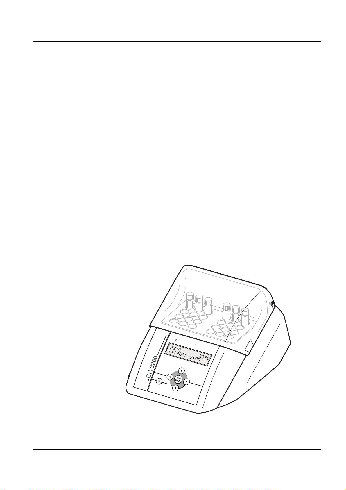
The thermoreactor CR 3200 is a dry temperature control device for
laboratory use. It facilitates and secures the digestion using reaction
cells.
The thermoreactor has 8 fixed temperature programs.
1: 148 °C for 120 minutes
2: 120 °C for 30 minutes
3: 120 °C for 60 minutes
4: 120 °C for 120 minutes
5: 100 °C for 60 minutes
6: 148 °C for 20 minutes
7: 150 °C for 120 minutes
8: 100 °C for 30 minutes
8 more temperature programs can be set up freely. The reaction
temperature can be adjusted from room temperature to 170 °C, the
heating time from 0 to 180 min.
The thermoreactor takes 24 reaction cells with an outer diameter of
16 mm.
ba76120e01 08/2012
5
Page 6
Overview CR 3200
1
2
3
4
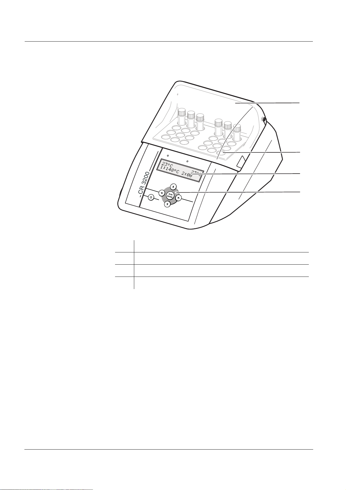
1.1 Components of the thermoreactor
1 Protection cover
2 Thermoblock with cell shafts
3 Display
4 Keypad
6
ba76120e01 08/2012
Page 7
CR 3200 Safety
2 Safety
This operating manual contains basic instructions that you must follow
during the commissioning, operation and maintenance of the
thermoreactor. Consequently, all responsible personnel must read this
operating manual before working with the thermoreactor. The operating
manual must always be available within the vicinity of the
thermoreactor.
Target group The thermoreactor was developed for use in the laboratory. Thus, we
assume that, as a result of their professional training and experience,
the operators will know the necessary safety precautions to take when
handling chemicals.
General safety
instructions
Other labels
The individual chapters of this operating manual use the following
safety labels to indicate different levels of danger:
Warning
indicates instructions that must be followed precisely in order to
prevent serious dangers to persons.
Caution
indicates instructions that must be followed precisely in order to
avoid slight injuries or damage to the instrument or the environment.
Note
indicates notes that draw your attention to special features.
Note
indicates cross-references to other documents, e.g. application
reports.
ba76120e01 08/2012
7
Page 8

Safety CR 3200
2.1 Authorized use
The authorized use of the thermoreactor is exclusively the heating of
samples in cells in a laboratory. The technical specifications as given
in chapter 8 T
ECHNICAL DATA must be observed. Only the operation and
running of the measuring instrument according to the instructions given
in this operating manual is authorized. Any other use is considered
unauthorized.
2.2 General safety instructions
This thermoreactor is constructed and tested in compliance with the EN
61010 safety regulations for electronic measuring instruments. It left
the factory in a safe and secure technical condition.
Function and operating
safety
The smooth functioning and operational safety of the thermoreactor
can only be guaranteed if the generally applicable safety measures and
the specific safety instructions in this operating manual are followed
during operation.
The smooth functioning and operational safety of the thermoreactor
can only be guaranteed under the environmental and electrical
operating conditions that are specified in chapter 8 T
ECHNICAL DATA.
If the thermoreactor was transported from a cold environment to a
warm environment, the formation of condensate can impair the
functioning of the measuring system. In this event, wait until the
temperature of the thermoreactor reaches room temperature before
putting the thermoreactor back into operation.
Caution
The thermoreactor is only allowed to be opened by personnel authorized by.
8
ba76120e01 08/2012
Page 9

CR 3200 Safety
Safe operation If safe operation is no longer possible, the thermoreactor must be taken
out of service and secured against inadvertent operation. Safe
operation is no longer possible if the thermoreactor
has been damaged in transport
has been stored under adverse conditions for a lengthy period of
time
is visibly damaged
no longer operates as described in this manual.
If you are in any doubt, please contact the supplier of the
thermoreactor.
Obligations of the
purchaser
The purchaser of this thermoreactor must ensure that the following
laws and guidelines are observed when using dangerous substances:
EEC directives for protective labor legislation
National protective labor legislation
Safety regulations
Safety datasheets of the chemical manufacturers.
ba76120e01 08/2012
9
Page 10

Safety CR 3200
10
ba76120e01 08/2012
Page 11

CR 3200 Commissioning
3 Commissioning
3.1 Scope of delivery
Thermoreactor CR 3200
Connection cable for mains connection
Operating manual
Warning
Always keep the original packing including the inner packing. If
you have to transport the instrument, the packing protects the instrument optimally from hard shocks.
The original packing is also required for the appropriate return
transport of the instrument if it has to be repaired.
Please note that the warranty does not cover damage caused by
inappropriate transport.
ba76120e01 08/2012
11
Page 12
Commissioning CR 3200
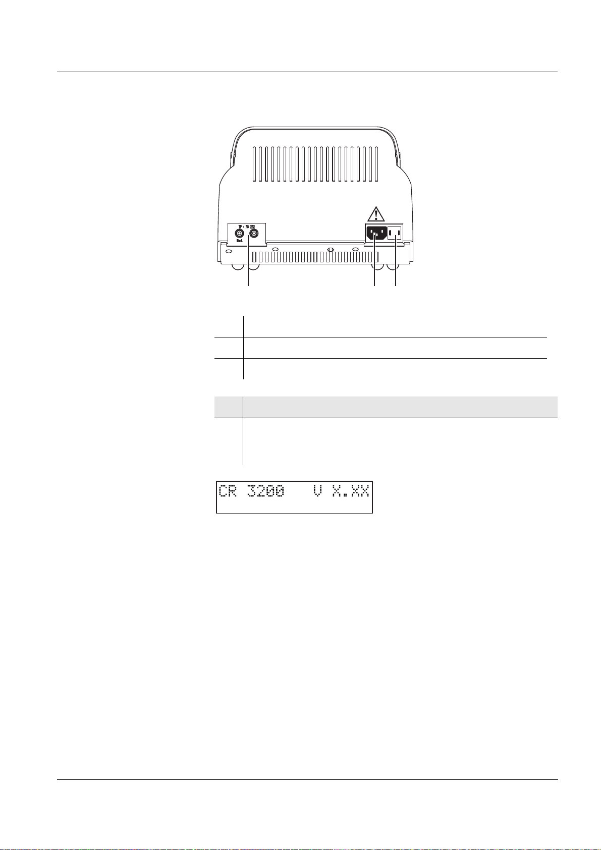
231
3.2 Initial commissioning
Note
The thermoreactor works at an ambient temperature of +5 °C to
+40 °C. When the thermoreactor was transported from a cold
environment to a warm environment, condensate may occur and cause
a malfunction. Wait until the thermoreactor has adjusted to the new
environmental conditions before putting it into operation again (see
also chapter 8 T
ECHNICAL DATA).
Setting up the
thermoreactor
Adjusting the mains
voltage
1 Place the thermoreactor firmly onto a heat-resistant
underground.
2 Make sure that there is enough space between the
thermoreactor and other instruments or devices that are heatsensitive.
12
3 Check whether the arrow on the housing points to the mains
voltage (115 or 230 V) given on the fuse holder (3) that is
provided by the mains.
4 If the wrong mains voltage is set, perform steps 5 to 7.
5 Pull out the fuse holder (3).
6 Turn the fuse holder (3) so that the arrow on the housing points
to the mains voltage (115 or 230 V) provided by the mains.
7 Push the fuse holder (3) in completely.
ba76120e01 08/2012
Page 13
CR 3200 Commissioning
231
Connecting the mains
cable
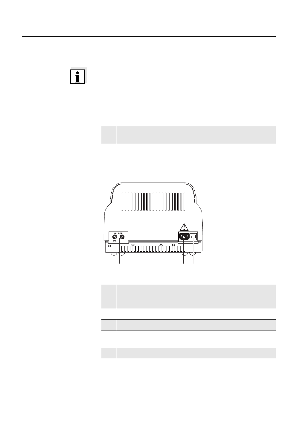
1 Socket for temperature probe or PC
2 Socket for mains plug
3 Fuse holder
8 Connect the mains cable to the socket 2 on the thermoreactor.
9 Connect the mains cable to an easily available mains socket.
The thermoreactor is now in the Standby mode.
The display shows the name of the instrument.
The thermoreactor is ready for operation.
ba76120e01 08/2012
13
Page 14

Commissioning CR 3200
14
ba76120e01 08/2012
Page 15

CR 3200 Basic principles of operation
4 Basic principles of operation
This chapter provides you with basic information on how to operate the
thermoreactor.
4.1 Operating and display elements
Using the six keys of the keypad (see section 4.1.1) you control the
thermoreactor.
Temperature values, available temperature programs or settings can
be viewed in the display (see section 4.1.2).
The control lamps above the operating panel are assigned to the
thermoblock. Their color (red or green) and their state (flashing or
illuminated) show the current operating state of the thermoreactor (see
section 4.1.3).
ba76120e01 08/2012
15
Page 16

Basic principles of operation CR 3200
4.1.1 Keys
Key Meaning
e
g
ge
4 6
8 2
On/off switch
Making or confirming a selection
or
Starting the timer for the reaction time (active
temperature program).
Keep g depressed and simultaneously press e:
Changing to the SETUP menu from the Standby mode
Changing between the temperature setting and the
reaction time setting (in the SETUP menu)
or
Canceling the active temperature program
Selecting the temperature program (program
selection)
or
Changing settings and switching between settings
(SETUP)
Starting the scrolling through settings by keeping the
key depressed
16
ba76120e01 08/2012
Page 17

CR 3200 Basic principles of operation
1
2
3
4
23°C 23°C
1:148°C 2:00
1
4.1.2 Display
Example: Program selection
1 Temperature in the thermoblock
2 Number of the temperature program
3 Specified temperature
4 Reaction time in hours and minutes
4.1.3 Control lamps (LEDs)
The control lamps above the operating panel are assigned to the
thermoblock and indicate the current operating state.
LED flashes is illuminated
green Program selection
red active temperature
program:
heating period or cooling
period
red and
green
If the control lamps are off the thermoreactor is in the Standby mode.
active temperature
program:
program canceling
selected
active temperature program:
reaction temperature reached
ba76120e01 08/2012
17
Page 18

Basic principles of operation CR 3200
4.2 Operating modes
The thermoreactor has three operating modes:
Standby
The display shows the model and version number of the
thermoreactor.
Using the g and e keys simultaneously takes you to the SETUP
menu. There you can:
– Edit the 8 temperature programs and the temperature test
program (setting the temperature and reaction time for the
programs 9 to 16 and T, see section 5.5.1)
– Set the display contrast (CONTRAST:0 to 9, see section 5.5.2)
– Activate a manual confirmation before the timer for the reaction
time is started (START TIMER:MAN. or AUTO, see section
5.5.3)
Program selection
After switching on with e the display shows the current
temperature value for the thermoblock. The second display line
shows the temperature programs and the temperature test program
to be selected if a reaction time of at least one minute has been set
(see section 5.5.1). The control lamps above he display light up
green.
Active temperature program
The display shows the current temperature value for the
thermoblock. The control lamps above the display light up or flash
red.
18
ba76120e01 08/2012
Page 19

CR 3200 Operation
23°C 23°C
4:120°C 2:00
5 Operation
5.1 Inserting the reaction cells
The reaction cells can either be inserted at room temperature or when
the thermoreactor has been preheated.
Caution
When dealing with chemicals always follow the safety data sheets
and the regulations for prevention of accidents.
Caution
Observe the analysis specifications of the test sets used.
Warning
The thermoblock can become very hot (170 °C).
There is danger of burning when the thermoblock is heated up.
Note
When cold reaction cells are inserted in the preheated thermoblock it
can cool down by approx. 3 °C.
1 Insert the filled reaction cells in the cell shafts.
2 Close the protection cover.
5.2 Starting a temperature program
1 Switch the thermoreactor on with e.
2 Select a temperature program with 8 2.
You can select from 8 predefined temperature programs and a
temperature test program (see section 5.5.1).
ba76120e01 08/2012
19
Page 20

Operation CR 3200
3 Start the displayed temperature program with g.
The control lamps for the thermoblock flash red.
The nominal reaction time (in hours and minutes) appears on
the display.
Note
The reaction temperature is reached when the temperature in the
thermoblock is in a range of ± 1 °C around the adjusted temperature
for two minutes constantly. The control lamps of the thermoblock will
then light up red.
Sequence with
automatic timer
Sequence with manual
timer
If the start of the timer for the reaction time has been set to automatic
in the SETUP menu (START TIMER:AUTO see section 5.5.3), the
reaction time automatically starts after the reaction temperature has
been achieved. The reaction temperature is kept constant during the
reaction time.
After the reaction time has expired the control lamps flash red.
The temperature program is finished.
The thermoreactor is in the program selection mode.
As soon as the thermoblock has cooled down to under 50°C, the
control lamps switch themselves off.
If the start of the timer for the reaction time has been set to manual in
the SETUP menu (START TIMER:MAN. see section 5.5.3), an S is
displayed in front of the nominal reaction time. With this setting the
thermoreactor controls the temperature until the timer for the reaction
time is started by pressing g.
4 Start the timer for the reaction time with g. The S in front of
the reaction time disappears.
20
The reaction temperature is kept constant during the reaction time.
The control lamps of the thermoblock will then light up red.
After the reaction time has expired the control lamps flash red.
Additionally, an acoustic signal sounds.
5 Using g confirm the end of the reaction time for each
thermoblock.
The temperature program is finished.
The acoustic signal is finished.
ba76120e01 08/2012
Page 21

CR 3200 Operation
The thermoreactor is in the program selection mode.
As soon as the thermoblock has cooled down to under 50°C, the
control lamps switch themselves off.
5.3 Stopping a temperature program
You can terminate a running program at any time.
1 Using 4 6, terminate the running temperature program.
The control lamp for the thermoblock flashes red/green.
The safety query STOP? is displayed.
2 Using g confirm the safety query STOP?.
The temperature program is finished.
The control lamps of the thermoblock will then light up green.
or:
Using 4 6, leave STOP?.
The query STOP? disappears from the display. The
temperature program is continued.
Note
While STOP? is displayed the temperature program goes on running.
As soon as a section of the temperature program is finished (e.g. after
the end of the heating period or after the end of the reaction time), the
STOP? display is overwritten.
5.4 Temperature test program
With the temperature test program, you can check the temperature in
the thermoblock with the aid of an external temperature probe that is
available as an accessory (see chapter 9 A
While the temperature test program is active, the display shows the
current temperature of the thermoblock and at the same time the
measured temperature value of the external temperature probe.
The thermoreactor functions correctly if the temperature of the external
temperature probe does not deviate from the nominal temperature
value by more than 2 °C.
If the deviations from the nominal value are greater, further measures
can be necessary (see chapter 7 W
HAT TO DO IF...).
CCESSORIES/OPTIONS).
ba76120e01 08/2012
21
Page 22

Operation CR 3200
Note
The external temperature probe has the same accuracy as the internal
temperature sensor.
5.4.1 Starting the temperature test program
Note
All other temperature programs are blocked while the temperature test
program runs.
1 Connect the external temperature probe to the socket at the
thermoreactor (see chapter 3 C
OMMISSIONING).
2 Insert the external temperature probe in a cell shaft.
3 Switch the thermoreactor on with e.
4 Using 8 2, select the temperature test program T.
5 Using g start the temperature test program T.
The first display line shows the nominal measuring time and the
temperature of the thermoblock. The second display line shows the
temperature of the external temperature probe. After the nominal
temperature has been reached, the measuring time is counted down in
the second display line.
During the temperature regulation phase, the thermoreactor saves the
measured temperature values of the external temperature probe in a
test report every 60 seconds.
As soon as the temperature test is finished, "PRINT" appears on the
display.
22
You can now output the measuring data of the temperature test to a PC
or printer.
You have the following options now:
Connect the thermoreactor with a PC and transmit the test report to
ba76120e01 08/2012
Page 23

CR 3200 Operation
CR 3200 V.X.XX
Tref = 148 C
1: Tblock = 147.5 C
2: Tblock = 147.6 C
3: Tblock = 147.7 C
. . .
. . .
a terminal program (see section 5.4.2).
Connect the thermoreactor with a printer and download the test
report to the printer (see section 5.4.2).
Leave the temperature test program with g.
The test report in the thermoreactor is erased in any case at the end.
5.4.2 Downloading the test report to an external printer/PC
To transmit the temperature test report to a printer or PC, a printer
cable or PC cable is required (see chapter 9 A
CCESSORIES/OPTIONS).
You can record the test report with the aid of a so-called terminal
program on the PC side.
Generally, a terminal program serves to establish a connection to a
meter at a data interface and to communicate with the meter via a
console on the display. A terminal program usually offers the possibility
to save the contents of the console in a text file or print it. If the terminal
program is connected to the thermoreactor, it can receive the
temperature test report and display it on the console.
Sample report
Downloading the test
report
Terminal programs are available by different manufacturers for
different operating systems. The "HyperTerminal" terminal program is
included in Windows (versions 95 to XP). It is in the program menu
under Accessories.
More detailed information can be taken from the user information of the
terminal program.
Precondition:
The temperature test is finished and PRINT is displayed (see page 5-
22).
1 Disconnect the external temperature probe from the
thermoreactor.
ba76120e01 08/2012
Note
When connecting the PC or printer cable observe the cable poling.
Data transmission is possible with the correct poling only.
23
Page 24

Operation CR 3200
1 Ref
2 TxD
Socket assignment
2 Connect the thermoreactor to the PC or printer. (Cable see
chapter 9 A
CCESSORIES/OPTIONS). To do so:
plug the reference plug (unmarked) in the "Ref" socket (1).
plug the signal plug (marked by a red ring) in the socket (2).
3 Start the terminal program on the PC.
4 Set the following transmission data in the terminal program:
Baud rate 4800
Handshake none
Parity none
Data bits 8
Stop bits 1
Record none
5 Start the data transmission with g.
After the transmission is finished the test report is deleted in
the thermoreactor.
24
ba76120e01 08/2012
Page 25

CR 3200 Operation
5.5 Settings
5.5.1 Editing a temperature program
The temperature programs 1 to 8 are installed permanently and cannot
be changed.
The temperature programs 9 to 16 and the temperature test program
can be edited according to individual requirements.
Note
For the temperature test program, a TFK CR external temperature
probe is required (available as an accessory, see chapter 9
CCESSORIES/OPTIONS).
A
1 Switch to the Standby mode.
2 Keep the g key depressed while you press e to sw itch to th e
SETUP menu.
SETUP and, in the second line, an editable parameter are
displayed.
3 Using 8 2 select a temperature program no. 9 to 16 or the
temperature test program.
4 Using g edit the selected temperature program.
The two parameters, temperature and time, are displayed.
The editing is marked on the display by *.
The selected parameter is marked by an arrow < or >.
5 Using 8 2 change the parameter (e.g. temperature ).
6 Using 4 6 switch to the other parameter.
ba76120e01 08/2012
7 Using 8 2 change the parameter (e.g. reaction time ).
8 Using g confirm the changes.
The marking on the display (*) disappears.
25
Page 26

Operation CR 3200
9 Using e leave the SETUP menu.
The changes are stored.
The thermoreactor is switched on (operation mode: program
selection).
5.5.2 Setting the display contrast
The display contrast can be set in 10 steps.
1 Switch to the Standby mode.
2 Keep the g key depressed while you press e to switch to the
SETUP menu.
SETUP and, in the second line, an editable parameter are
displayed.
3 Using 8 2 select CONTRAST.
4 Using g edit the contrast setting.
The editing is marked on the display by*.
5 Using 8 2 set the contrast from 0 to 9.
6 Using g confirm the changes.
The marking on the display (*) disappears.
7 Using e leave the SETUP menu.
The changes are stored.
The thermoreactor is switched on (operation mode: program
selection).
26
5.5.3 Setting the timer for the reaction time
After the start of a temperature program the thermoblock starts heating
up. Depending on the setting, the timer for the reaction time starts
automatically after the reaction temperature has been reached or only
after confirmation by keypressing.
ba76120e01 08/2012
Page 27

CR 3200 Operation
With the setting START TIMER:AUTO the timer for the reaction time
starts immediately after the reaction temperature has been reached.
With the setting START TIMER:MAN. the timer for the reaction time
starts after confirmation by keypressing only.
1 Switch to the Standby mode.
2 Keep the g key depressed while you press e to sw itch to th e
SETUP menu.
SETUP and, in the second line, an editable parameter or a
temperature program are displayed.
3 Using 8 2 select START TIMER.
4 Using g set the start of the timer for the reaction time.
The editing is marked on the display by *.
5 Using 8 2 select MAN. or AUTO.
6 Using g confirm the changes.
The marking on the display (*) disappears.
7 Using e leave the SETUP menu.
The changes are stored.
The thermoreactor is switched on (operation mode: program
selection).
ba76120e01 08/2012
27
Page 28

Operation CR 3200
28
ba76120e01 08/2012
Page 29

CR 3200 Maintenance, cleaning, disposal
231
6 Maintenance, cleaning, disposal
6.1 Maintenance
The CR 3200 thermoreactor is maintenance-free.
6.2 Exchanging the fuses
1 Disconnect the line power cable from the thermoreactor.
2 Pull out the fuse holder (3).
3 Exchange one or both fuses (6.3 AT).
4 Turn the fusion holder (3) so that the arrow on the housing
points to the line voltage (115 or 230 V) provided by the power
line.
5 Push the fusion holder (3) completely in.
ba76120e01 08/2012
29
Page 30

Maintenance, cleaning, disposal CR 3200
6.3 Cleaning the enclosure
Wipe the thermoreactor with a damp cloth.
Caution
The housing is made of synthetic material. Thus, avoid contact
with acetone or detergents that contain solvents. Remove any
splashes immediately.
6.4 Cleaning the thermoblock of spilled cell contents
If liquid penetrated a thermoblock (e.g. from a cell), clean the
thermoblock as follows:
Warning
Cells can contain poisonous or corrosive substances. If the content has been set free observe the danger notes on the cell. If necessary take the corresponding protective measures (protective
goggles, protective gloves etc.).
Warning
The thermoblock can become very hot (170 °C). There is danger
of burning when the thermoblock is heated up.
1 Switch off the thermoreactor and disconnect the power plug.
2 Allow the thermoreactor to cool down.
3 Unscrew the cover plate on top of the thermoblocks.
4 Clean the cover plate, block surfaces and borings with a damp
cloth.
5 Screw on the cover plate again.
Note
Discoloration that remains on the thermoblock and cover plate does not
affect the functioning of the thermoreactor.
6.5 Disposal
Dispose of the thermoreactor as electronic waste at an appropriate
collection point. It is illegal to dispose of the thermoreactor in household
refuse.
30
ba76120e01 08/2012
Page 31

CR 3200 What to do if...
7 What to do if...
There is nothing on the
display
Bars are displayed
instead of the
temperature (-°C)
Cause Remedy
– The power supply is
interrupted
Cause Remedy
– With an active
temperature test program:
the signal of the external
temperature probe was
not recognized
– In the program selection
mode: internal
temperature probe
defective
– Check mains cable and
connections
– Exchange the fuses
– Repair by service department
– Connect the temperature
probe
– Repair by service department
– Repair by service department
Temperature deviation
during the temperature
test program
Cuvette emptied /
thermoblock
contaminated
Cause Remedy
– Bad thermal contact
between the external
temperature probe and the
thermoblock
Cause Remedy
– e. g. leaking cuvette – see section 6.4
– Use original accessories only
– Close the protection cover
during the temperature test
– Contact the service
department
ba76120e01 08/2012
31
Page 32

What to do if... CR 3200
32
ba76120e01 08/2012
Page 33

CR 3200 Technical Data
8Technical Data
Reactor type Dry temperature control device
with safety cover
Cell shafts 2 x 12 cell shafts for reaction
cells 16 ± 0.2 mm
Reaction time setting 20 min, 30 min, 60 min, 120 min
(via fixed programs)
8 freely adjustable programs:
0...180 min
Temperature setting 100 °C, 120 °C, 148 °C, 150 °C
via fixed programs
and 8 freely adjustable
programs:
Room temperature ...170 °C
Controlling accuracy ± 1 °C ± 1 Digit
Temperature stability ± 0.5 K
Overtemperature protection 190 °C ± 5 °C
Heating time (with empty
thermoblock) from 25 °C to
Temperature of the enclose at
an environmental temperature
of 25 °C
Output unidirectional RS232 interface
Power supply 230 VAC 50 Hz ± 15 %
100 °C approx. 5 min
120 °C approx. 7 min
148 °C approx. 10 min
< 30 °C with a block temperature
of 148 °C
with 2 banana sockets for:
external temperature probe
or
PC cable
115 VAC 60 Hz ± 15 %
Power consumption: 560 W
Fuses 2 x 6.3 AT
ba76120e01 08/2012
Enclosure PC ABS, recyclable, high
temperature resistant
Protective class I according to DIN VDE 0700
part 1/11.90
33
Page 34

Technical Data CR 3200
Insulation group Insulation group: B according to
DIN VDE 0110/11.72
Overvoltage category II
Protection IP 20 according to DIN 40050
Ambient temperature Storage -25 °C to +65 °C
Operation +5 °C to +40 °C
Climatic class 2 according to VDI/VDE 3540
Relative humidity:
Yearly mean: < 75 %
30 days /year: 95 %
Other days: 85 %
Light dew: yes
EMC EN61326
FCC Class A
Test certificates cETLus, CE
Dimensions D x W x H: 312 x 255 x 185 mm
Weight: 4kg
Safety standards EN61010
UL3101
CAN/CSA C22.2-1010
EN61010-2-010
IEC-CAN/CSA C22.2-
1010.2.010
34
ba76120e01 08/2012
Page 35

CR 3200 Accessories/Options
9 Accessories/Options
Designation Accessory
TFK CR External temperature probe for the monitoring
of test equipment of the CR 3200 and CR 4200
thermoreactors
AK CR/PC PC cable for thermoreactors, CR 3200 and
ba76120e01 08/2012
35
Page 36

Accessories/Options CR 3200
36
ba76120e01 08/2012
Page 37

CR 3200 Index
10 Index
A
Authorized use ...........................................8
C
Commissioning ........................................11
Components of the thermoreactor ...............6
Control lamps (LEDs) ...............................17
D
Display ....................................................17
F
Fuses ......................................................29
K
Keys .......................................................16
M
Maintenance ............................................29
Temperature test program
starting
Trouble shooting ..................................... 31
.............................................. 22
W
What to do if... ........................................ 31
O
Operating and display elements ................15
Operating modes .....................................18
Operating safety ........................................8
Outputting data to a PC ............................23
Outputting data to a printer .......................23
P
PC ..........................................................23
Program selection ....................................18
S
Safety measures ........................................7
Scope of delivery .....................................11
Setting the display contrast .......................26
Standby ..................................................18
T
Temperature program
editing
starting ..............................................19
stopping .............................................21
Temperature program active .....................18
...............................................25
ba76120e01 08/2012
37
Page 38

Index CR 3200
38
ba76120e01 08/2012
Page 39

CR 3200 Contact Information
11 Contact Information
11.1 Ordering & Technical Support
Telephone
Fax
: (937) 767-1058
Email
Mail: YSI Incorporated
Internet
When placing an order please have the following information available:
YSI account number (if available) Name and Phone Number
Model number or brief description Billing and shipping address
Quantity Purchase Order or Credit Card
: (800) 897-4151
(937) 767-7241
Monday through Friday, 8:00 AM to 5:00 PM ET
: environmental@ysi.com
1725 Brannum Lane
Yellow Springs, OH 45387
USA
: www.ysi.com
11.2 Service Information
YSI has authorized service centers throughout the United States and
Internationally. For the nearest service center information, please visit
www.ysi.com
directly at 800-897-4151.
When returning a product for service, include the Product Return form
with cleaning certification. The form must be completely filled out for an
YSI Service Center to accept the instrument for service. The Product
Return form may be downloaded at www.ysi.com
‘Support‘ tab.
and click ‘Support’ or contact YSI Technical Support
and clicking on the
ba76120e01 08/2012
39
Page 40

Contact Information CR 3200
40
ba76120e01 08/2012
Page 41

Page 42

Xylem
1) The tissue in plants that brings water upward from the roots;
2) a leading global water technology company.
We’re 12,500 people unified in a common purpose: creating innovative solutions
to meet our world’s water needs. Developing new technologies that will improve
the way water is used, conserved, and re-used in the future is central to our work.
We move, treat, analyze, and return water to the environment, and we help people
use water efficiently, in their homes, buildings, factories and farms. In more than
150 countries, we have strong, long-standing relationships with customers who
know us for our powerful combination of leading product brands and applications
expertise, backed by a legacy of innovation.
YSI
1725 Brannum Lane
Yellow Springs, OH 45387
Tel: +1 937-767-7241; 800-765-4974
Fax: +1 937-767-1058
Email: environmental@ysi.com
Web: www.ysi.com
©Xylem Inc, October 2012
 Loading...