

Page 1

610D Display/Logger
610DM Display/Logger
Environmental
Monitoring
Systems
Page 2

Page 3

CONTENTS
ECTION
S
ECTION
S
ECTION
S
ECTION
S
ECTION
S
ECTION
S
ECTION
S
ECTION
S
SECTION 8 WARRANTY AND SERVICE INFO ............................................................................. 30
APPENDIX A REQUIRED NOTICE .....................................................................................................35
APPENDIX B ACCESSORIES............................................................................................................... 36
1 GETTING STARTED.............................................................................................................. 3
1.1 BATTERIES AND CHARGING ...................................................................................................3
1.2 CONNECTING TO A SONDE.....................................................................................................3
1.3 POWERING UP...........................................................................................................................5
2 USING THE KEYBOARD.....................................................................................................6
3 CHOOSING WHICH READINGS TO DISPLAY ................................................................6
3.1 SETTING UP AND USING THE SITE LIST ...............................................................................7
USING THE SITE LIST FOR CAPTURE, LOG AND ADD FILES ......................................................9
4 LOGGING ..............................................................................................................................9
4.1 SETTING UP A SONDE FOR UNATTENDED LOGGING......................................................12
5 FILES.................................................................................................................................... 12
5.1 UPLOADING LOGGED FILES................................................................................................ 12
5.2 TRANSFERING FILES TO A COMPUTER.............................................................................. 13
6 SAMPLING..........................................................................................................................14
6.1 STASH MEMORY......................................................................................................................14
6.2 CAPTURE AND ADD MEMORY..............................................................................................15
6.3 MARK FEATURE......................................................................................................................16
7 YSI 610 MENU .................................................................................................................... 19
7.1 RUN........................................................................................................................................... 21
7.2 SETUP YSI 610.......................................................................................................................... 23
7.3 COMMUNICATIONS................................................................................................................23
7.4 CALIBRATION Mode................................................................................................................25
7.5 SETUP PARAMETERS and SETUP SENSORS.........................................................................26
7.6 DEPLOY MODE................................................................................................................. ....... 26
7.7 LOGGING MODE (YSI 610 DM only)......................................................................................27
7.8 FILE SYSTEM (610 DM only)...................................................................................................28
8 TECHNICAL INFORMATION...........................................................................................29
8.1 SOFTWARE UPDATES.............................................................................................................29
8.2 LOADING NEW SOFTWARE....................................................................................................29
i
Page 4

ii
Page 5

SECTION 1 GETTING STARTED
The YSI Display and Logger series instruments are powerful, hand held microcomputers
that allow the user to display sonde readings, configure sondes, store and recall data,
upload data from sondes and transfer data to computers for analysis and plotting.
1.1 BATTERIES AND CHARGING
An internal NiMH battery pack powers the YSI 610. This supply is sufficient to run a
YSI 610 connected to a sonde for 6-8 hours. If the sonde is being powered separately, the
YSI 610’s batteries can last much longer. The sondes can be powered by their internal
batteries (6920, 6600 and 600XLM only), or by using a power supply such as the YSI
6038.
To ensure that you get maximum operational time from your hand-held display/logger,
the user should follow the procedures below:
1) Place your display/logger on charge for approximately 24 hours.
2) After 24 hours, take the display/logger off the charge and switch it on. Leave the
display/logger on until the battery is fully discharged.
3) Repeat steps one and two at least two more times. This ensures that the battery is
charged to its maximum capacity.
4) Do not charge the batteries for more than 48 hours.
If the above steps are not followed, it may result in limited operational time of your
display/logger and limited lifetime of your terminal’s battery pack. When the YSI 610’s
batteries get low, the YSI 610 beeps. This provides approximately a one-hour warning
before the YSI 610 will turn itself off. A wall-mount power supply is supplied with the
YSI 610 to recharge the batteries. An optional automotive cigarette lighter adapter is also
available.
1.2 CONNECTING TO A SONDE
Since YSI 6-Series sondes do not have displays or controls, users must communicate to
them with a PC or terminal and emulation device. Figure 1 is a diagram of the YSI 610
connected to any 6-Series sonde.
YSI Incorporated Displays and Loggers 3
Page 6
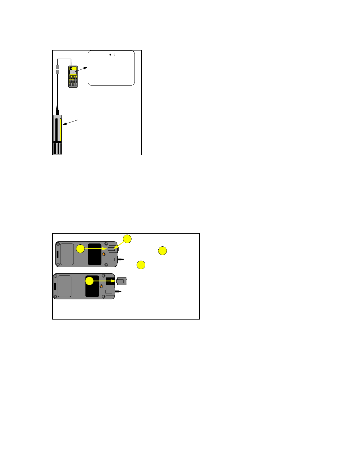
Figure 1
Environm ental
Monitoring
YSI
Systems
610-DM
610 Handheld Display
RUN
TMP 20.54
CND 0.687
DO% 97.5
DOc 38.0
pH 8.32
NO3 2.35
SpC 0.750
SAL 1.42
DO 8.56
DEP 10.12
ORP 90.2
TRB 2.3
68
20
The 6-Series Sonde.
There are two slide plugs on the back of the YSI 610. One plug is for power and the
other is for communications to a sonde or computer. They are not interchangeable. In a
laboratory situation, you will often use the AC adapter plug to power and charge your
YSI 610. Because this plug is not intended to be watertight, replace it with the blanking
plug when taking the YSI 610 into the field. An optional slide plug adapter for
connecting your YSI 610 to an external battery is also available.
Figure 2
Bottom View
..............
..............
....................................
....................................
....................................
....................................
....................................
2
....................................
....................................
....................................
....................................
....................................
2
1
Press in at with one
1
thumb while pushing out
at with the other
2
thumb.
Install modules by aligning
contacts and gently
pushi ng
in until they snap into place.
Two slide plug cable adapters are available for the communications plug. One is for
communication with a PC and terminates in a 9 pin miniature sub-D connector (DB-9).
When communicating with a PC, be sure to use a null modem cable. The other adapter is
for use with a sonde and terminates in an 8 pin, military style connector (MS-8). Plug the
MS-8 end of the cable into the sonde cable and the other end into the YSI 610.
YSI Incorporated Displays and Loggers 4
Page 7
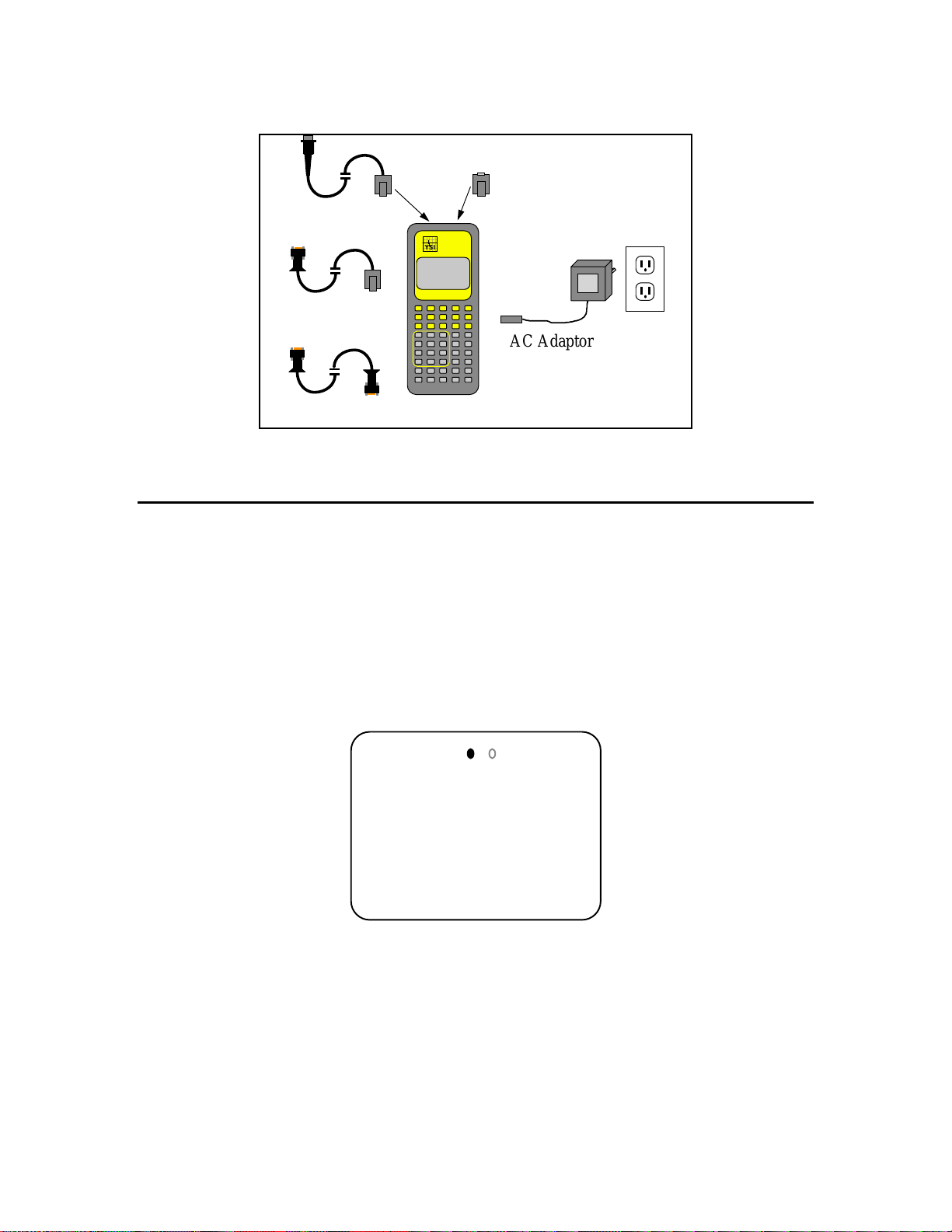
Figure 3
Power Jack Module
MS-8 Pigtail
Environmental
Monitoring
YSI
Systems
610-DM
DB-9 Pigtail
AC Adaptor for 120 VAC
Null Modem Cable
1.3 POWERING UP
After the YSI 610 is shipped, the batteries may need a few minutes of charging before the
unit can be turned on. Normally, whenever the AC adapter is plugged in, the YSI 610
turns itself on. To turn the YSI 610 off when the AC adapter is plugged in, press the
Power button, wait for the power up display to appear and then press the Power button
again. Do not allow the YSI 610 to charge more than 48 hours continuously.
With a sonde plugged in, the YSI 610 powers up into the Run mode and displays
readings.
RUN
TMP 20.54
CND 0.687
DO% 97.5
DOc 38.0
pH 8.32
NO3 2.35
The message, “No Sonde in Use” may appear occasionally while the YSI 610 is trying to
establish communication to a sonde. If the message does not go away after 60 seconds
check the cables, power and baud rate selection on both the YSI 610 and the sonde to
make sure that they are working properly, and that the baud rates agree (See Section 2,
Sondes of the YSI 6-Series Operations Manual for information about the proper baud
rate).
SpC 0.750
SAL 1.42
DO 8.56
DEP 10.12
ORP 90.2
TRB 2.3
YSI Incorporated Displays and Loggers 5
Page 8

SECTION 2 USING THE KEYBOARD
To select different menu options, use the arrow keys to highlight the name of the menu
that you want to open, and press the Enter key. To return to the previous menu, press the
Esc key.
Information can be entered into the YSI 610 when you see a blinking cursor within a
highlighted item. If you wish to change the highlighted information, type in the new
information, and press Enter. You can enter information in upper or lower case.
Durations and intervals, which appear on logging and deployment menus, are entered in a
special way. Values may be entered in units of seconds (s), minutes (m), hours (h) or
days (d). You must type a number followed by a letter (press Shift after typing the
numeric portion). Thus 15 seconds is entered as "15s", and 36 hours is entered as "36h".
The upper right corner of the screen indicates the keyboard shift status by showing "shft"
or "caps". If you wish to type a number instead of a letter, press the shift key and “shft”
will disappear. When the “shft” appears in the upper right corner of the screen, letters can
be typed. The YSI 610 automatically changes the shift status when it expects
numeric/text input. The “caps” appears in the upper right corner when you hit the caps
key to type capitalized letters (useful for naming files).
When the menu is too large to fit on the screen, arrow symbols appear in the upper or
lower corners. To see the part of the menu that is not shown, use the Arrow keys, and the
screen will scroll as necessary.
SECTION 3 CHOOSING WHICH READINGS TO
DISPLAY
The Setup Sensors and Setup Parameters menus of the YSI 610 allow you to display or
change the active sensors and parameters that are in the sonde. Both menus are listed in
the Main menu and have similar formats. To select or deselect an item in these menus,
highlight it and press Enter. You will rarely use the Setup Sensors menu, except when
you are first setting up your sonde after purchase, and only occasionally use the Setup
Parameters menu.
The Setup Sensors menu in the YSI 610 can not detect the presence or absence of a
particular sensor in the sonde. So regardless of which sensors are installed in your sonde,
all possible sensors are listed in the YSI 610 Setup Sensors menu. If you activate a
sensor that isn’t really connected, you will see false readings for that sensor, because the
YSI 610 and the sonde will believe whatever you enter.
YSI Incorporated Displays and Loggers 6
Page 9

RUN MODE
You access the Run mode by selecting Run from the YSI 610 Main menu, or by
powering up the YSI 610 with a sonde already connected. In the Run mode, the YSI 610
constantly requests live data from the sonde and displays it on the screen. To go to the
YSI 610 Main menu from the Run mode, press the Esc key.
3.1 SETTING UP AND USING THE SITE LIST
A feature of the YSI 610-DM (but not the YSI 610-D) allows you to place a list of “site
names” into memory to eliminate having to type them in during fieldwork. While using
the YSI 610-DM in the Run mode, you may press the “C” key (capture), “A” key (add)
or “M” key (marked) to view the Site List. Choose a site name from the list, or type in a
new name and confirm creating a new file if necessary. Press Enter, and the data will be
added or captured to this file. Each of these features are discussed in further detail in this
section.
There are two approaches to setting up and using the Site List feature. One allows you to
designate a descriptive file name and then add or capture data to this file at various times.
For example, you may decide to sample at “bridge1” each day for 14 days and capture
readings for several minutes each time. When you review or upload this file it will
contain 2 weeks of data, time and date stamped. This data is specific to “bridge1” site
and all of the data are in one file. If you want to collect data at another site (e.g.,
“bridge2”), you need to open a second file.
The second approach allows you to collect all readings for a particular field trip into one
file. For example, you may decide to sample at “bridge1”, then “bridge2”, then to
“uplake”, and so on. When setting up this file (automatically named “marked” by the
YSI 610-DM), you list a descriptive name in the “file” prompt to describe the site, then
assign a number in the “site” prompt that corresponds to this site. This mark number is
important because it is the key identifier when you view the readings at a later time.
Again, the advantage of “marked” file is that you can store readings from many sites in
one file and be able to identify the sites later. This may be your approach of choice on a
one day trip to multiple sites.
USING THE SITE LIST WITH THE MARKED FILE
The Site List is accessed through the Setup YSI 610 menu. If the site list is empty,
“make NEW entry” appears and prompts you to type in a new file name.
When using the Mark feature, there is only one file name, “marked”. All readings that
are stored using the “m” prompt during Run mode are stored to the file name “marked”.
IMPORTANT: You can only set up “marked” file by pressing the “m” key in the Run
mode. You can not type in the word “marked” to create this file. Once you have
YSI Incorporated Displays and Loggers 7
Page 10

collected readings under the pre-assigned site names, you may rename “marked” file to a
file name of your choice using submenu FILES.
In this mode, you can set up a site list using a Mark Name and a Mark Number. In the
Site List use the File item to hold the Mark Name, and the Site item to hold the Mark
Number. Use any combination of alpha/numeric characters (we recommend using 8
characters max for compatibility with DOS based systems) for the Mark Name, but for
the Mark Number you must enter numeric values (-99999 to 999999). You will likely
use positive numbers beginning with 1, then 2 and so on.
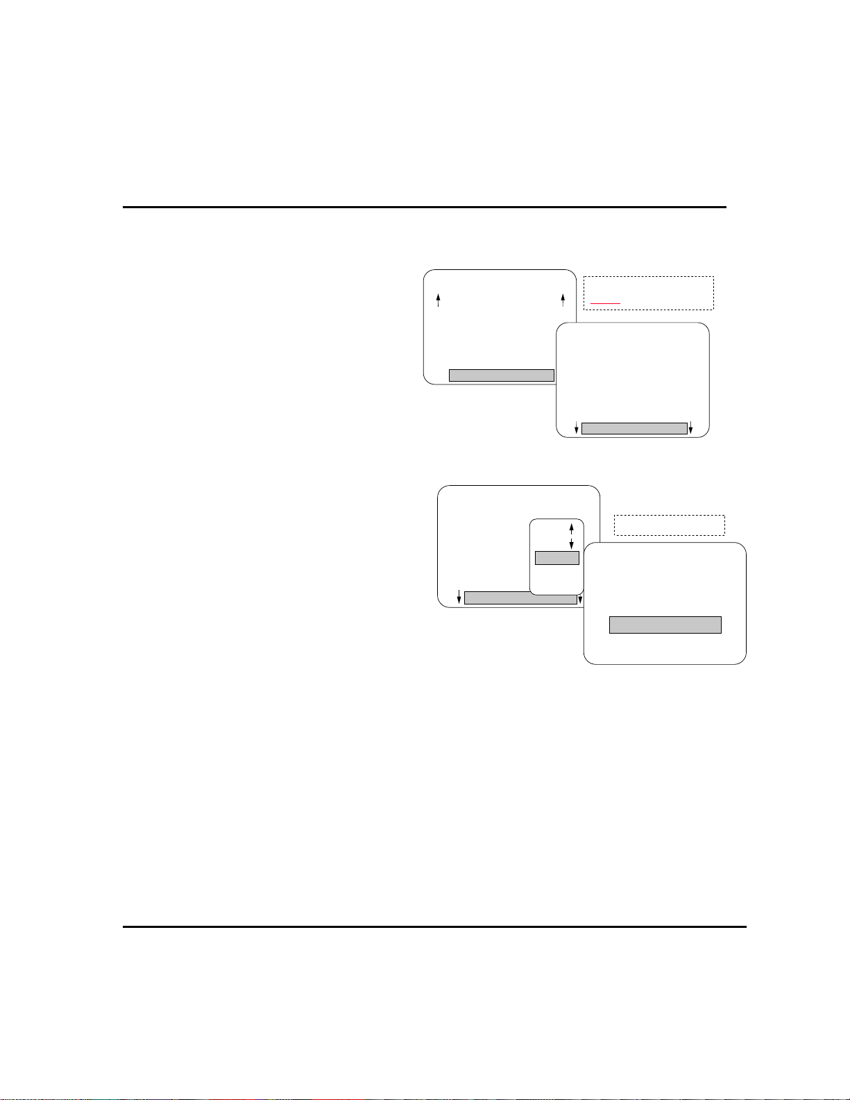
From the YSI 610’s Main menu, select
Setup YSI 610 and then select Setup
Site List. If no sites have been entered,
the “make NEW entry” screen appears.
To modify an existing list, press Enter,
then choose from the pop-up menu. To
enter a new site, choose Insert. Using
the example shown, type in “spillway”
and press Enter to add to the list.
SETUP
Date: 5/20/96
Time: 10:24:36
Dump 610 Setup
Delete All Files
Setup Site List
shft
SITELIST
headwtrs
bridge1
bridge2
uplake
midlake
spillway
Create a list of sites
you go to the field.
before
To correctly format this site for Mark status, highlight “Site” and enter a numeric value to
complete this entry. Using this
example the number “6” is used to
identify the site “spillway”.
While in the Run mode, press the “m”
key. Select the site name by
highlighting it to begin the process of
collecting readings.
SITELIST
headwtrs
bridge1
bridge2
uplake
midlake
Move
Move
Insert
Insert
Revise
Delete
Enter a file name.
SITE
Make NEW Entry
File:spillway
Site:
Remember that when you review data from the “marked” file, lines of data from the site
“spillway” will be labeled as “sample
6”. Each of the sites have
corresponding numbers. When you set
up the sites, we recommend that you
write down the list for later reference to
correlate names with numbers.
SITE
Make NEW Entry
File:spillway
Site:
Enter a mark number that
corresponds to the name.
SITE
Make NEW Entry
File:spillway
Site:6
YSI Incorporated Displays and Loggers 8
Page 11
USING THE SITE LIST FOR CAPTURE, LOG AND ADD FILES
The Site List is accessed through the Setup YSI 610 menu.
From the YSI 610 Main menu select
Setup YSI 610, and then select Setup Site
List. If no sites have been entered, “make
NEW entry” appears. To modify an
existing list, select an existing name, press
Enter and choose from the pop-up menu.
To enter a new site, choose Insert. Type in
“spillway” and press Enter to add to the
SETUP
Date: 5/20/96
Time: 10:24:36
Dump 610 Setup
Delete All Files
Setup Site List
shft
SITELIST
Create a list of filenames
you go to the field.
before
headwtrs
bridge1
bridge2
uplake
midlake
spillway
list.
By typing information after “Site:”, you may
further describe your site. This will not
appear in the file name list. The information
typed under “Site” only appears in the
header information during review of files
using the YSI 610 or YSI software. No
entry is required under “Site” for Add,
Capture and Log functions. A numeric value
is required if the Mark function is used.
SITELIST
headwtrs
bridge1
bridge2
uplake
midlake
Move
Move
Insert
Insert
Revise
Delete
Enter a mark name.
SITE
Make NEW Entry
File:spillway
Site:
The Site List can be kept in any order. It is suggested that you arrange it in the order that
you visit your sites. Making an entry on the Site List does not create a file, it only stores a
file name for future use. The file name will not appear in the Site List until data is stored
in the file.
There are different kinds of files for each of the three types of storage: Add, Capture and
Log. The file type is fixed after the first set of readings is stored to the file. If you decide
to use more than one type of storage, then you might want to make that clear in the file
name itself by adding “c”, “a”, or “l” as a suffix to the file name.
SECTION 4 LOGGING
Logging refers to the collection of a set of readings at regular intervals. There are two
different applications of the YSI 610 related to logging.
YSI Incorporated Displays and Loggers 9
Page 12

Some 6-Series sondes (6920, 6600 and 600XLM) have on-board memory and power.
These sondes can log readings to sonde memory for days or weeks at a time. You may
use the YSI 610-D or YSI 610-DM to setup one of these sondes for deployment,
disconnect the sonde and allow it to log readings on its own. Then use the YSI 610 to
upload files from the sonde.
The second application uses YSI 610-DM memory to store readings from any of the 6Series sondes. Since the readings are being logged to YSI 610-DM memory, sonde
memory and on-board power are not required. During logging, the YSI 610 can not do
anything else. While the YSI 610 can readily withstand short exposure to rain, it can not
be left out in the weather for extended periods of time. For these reasons, the YSI 610 is
best suited for short term logging applications.
LOGGING TO THE YSI 610-DM
The YSI 610-DM can log sample data directly to its internal memory from any 6-Series
sonde. Logging produces a file in the standard YSI file format, capable of being uploaded
to a PC and processed by EcoWatch for Windows.
NOTE: If you log files to the 610DM, only the parameters that are active in the Report
Menu will be available to the PC software. For example, if only DO mg/L is activated in
Report during logging, it will not be possible to later generate DO% values. This is
different from files that are logged to sonde memory where DO% would be available as a
calculated parameter in EcoWatch software. It is important to be certain that all desired
parameters are active in the Report Menu before beginning a 610 logging study.
When logging with the 610DM, the sensors will be turned off between logged samples,
affecting the manner in which the DO calibration should be carried out. First, when
setting up the sonde, the DO warm up time in the sonde’s Advanced Sensor menu is set
to the same value as the DO warm up time that is used to set up the 610DM logging
study. Second, After establishing the connection between the sonde and the 610DM, you
must turn on Autosleep RS232 in the sonde’s Advanced Setup menu. This can be done by
using Smart Terminal as described in Section 7.3, Communications . Third, proceed
directly to the Calibrate menu of the 610DM after Autosleep is activated. If you activate
Run mode, Autosleep will be deactivated. Follow the calibration procedures for DO as
described in Section 7.4, Calibration Mode. The calibration will occur automatically
after a countdown of the warm up time. Finally, proceed to the Logging menu and begin
the study as described below.
To begin logging with any sonde, select the Logging menu from the YSI 610 Main
menu. Four sub-menu choices are displayed.
YSI Incorporated Displays and Loggers 10
Page 13

(1) The Setup Header menu allows
you to specify control and timing
information for the deployment. Be
sure to set a file name and an interval.
We recommend that warm-up time be
set between 40 and 60 seconds.
(2) The Setup Filter menu allows
you to automatically discard samples
that do not meet your criteria. This
feature is rarely used.
LOG
Setup Header
Setup Filter
Start 610 Logging
Information
Warmup Time allows
DO probe to stablize.
Time is in seconds.
Enter filename and site.
Start date and time may
be typed in as “now”.
LOG
File: downstr7
Site: ysprings
StDate: 5/15/96
StTime: 21:00:00
Duration: 24hrs
Interval: 30min
WarmupTime: 40
shft
(3) The Start YSI 610 Logging menu begins the logging session that was specified in the
Setup Header and Setup Filter menus. If the file name specified already exists and was
created by Logging on the YSI 610, new data will be appended to the file. If the file
name does not exist, you will be asked if you want to create it, asked to enter a site name,
and asked if you want to enter the weather info. Pressing the Esc or Power keys
terminates logging. Logging stores all parameters to the data file even though only 12 fit
on the screen.
If the sonde is equipped with a wiping turbidity probe, the probe will be cleaned
automatically before each sample but only if time permits. Cleaning takes up to 24
seconds, and the YSI 610-DM makes sure that cleaning will end at least 30 seconds
before the sample. You set the number of wipes in the Sonde main menu, see 2.9,
Sonde menu of the YSI 6-Series Operations Manual. When the YSI 610 is started, the
number of wipes is included in the Logging screen. This allows you to verify that wiping
will occur.
LOG
Setup Header
Setup Filt er
Start 610 Logging
Information
Countdown in seconds
to first logged reading.
LOG
38
Logging...
Warmup Time: 40
Interval: 24hrs
Duration: 30min
LOG
Setup Header
Setup Filter
Start 610 Logging
Information
Flashes on momentarily
when readings are stored.
LOG
12:30:00 SAMPLE
TMP 20.54
CND 0.687
DO% 97.5
DOc 38.0
pH 8.32
NO3 2.35
SpC 0.750
SAL 1.42
DO 8.56
DEP 10.12
ORP 90.2
TRB 2.3
YSI Incorporated Displays and Loggers 11
Page 14

(4) The Logging Information screen tells
you how much space is available for
additional logging, and how much time this
corresponds to in Logging mode.
LOG
Setup Header
Setup Filter
Start 610 Logging
Information
Available memory and
historical information.
LOG
Free memory: 24K
Memory would hold
0.26 hours of data
Logging to downstr7
Ended by Esc Key
At 5/16/96 19:38:27
4.1 SETTING UP A SONDE FOR UNATTENDED LOGGING
The data logging discussed here refers to logging by the sonde into its own “sonde”
memory. This logging is completely separate from the YSI 610-DM Logging, Capture
and Add features which record data into the YSI 610-DM memory. The function of the
YSI 610 is to communicate with the sonde, to set logging parameters and to start or stop
the logging function. (Note that sondes without batteries must have an external power
source to log.)
To set up a sonde for logging, select Deploy Sonde from the Main menu.
The YSI 610 communicates with the Sonde
Main menu. Choose Run and then choose
Unattended Sample. Enter a file name and a
logging interval, then choose the last item on
the menu, Start logging. Finally, the sonde
asks for confirmation before actually starting
the logging run. Logging will begin at the
next even multiple of your logging interval.
DEPLOY
Interval=00:15:00
Start date= 07/17/96
Start time=18:00:00
Duration days=14
File=clrlake3
Site=Clear Lake
Enter file/site name, and
timing info, then scroll
down to Start Logging.
DEPLOY
Bat volts: 9.1
Bat life 21.2 days
Free mem 18.9 days
1st sample in 8 mins
View params to log
Start logging
Before starting, you should check Free Mem and Bat Life, to make sure that you have
the capacity to log for your intended deployment time. It is strongly recommended that
you log a few readings and view them before deploying the sonde. This will verify that
you have set it up properly.
SECTION 5 FILES
5.1 UPLOADING LOGGED FILES
Uploading a file from a sonde does not change the sonde files in any way. Only
formatting flash disk will delete files. To upload the data in a file, you do not need to
stop logging.
YSI Incorporated Displays and Loggers 12
Page 15

If you get a “No Sonde” message that persists for more than a 60 seconds, check the
cabling, batteries or power, and baud rate.
From the YSI 610 Main menu go to the Communications menu and select Kermi t YS I
610 < Sonde. You will see the sonde’s File menu. From that menu choose Upload. A
list of files will be displayed. Select the file you want and then select Proceed. After
choosing a file format, the upload will begin. You will see several status counters on the
YSI 610 screen. Any errors that occur during the upload are detected and corrected by
the YSI 610. But if the counters do not advance, press Esc to abort the upload, and try
again.
If the file is the last file in the directory ( or the currently-active file), you may use the
Quick Upload selection to upload the entire file.
When the upload is done, you will see "Successful" on the YSI 610 screen. Press the YSI
610’s Esc key twice to get back to the YSI 610 Main menu. Then select File System and
press Enter. You may now view the data file.
5.2 TRANSFERING FILES TO A COMPUTER
Run EcoWatch for Windows software on your PC, then select Settings from the Comm
menu. Verify the Baud Rate is 9600, and that the Com port is correctly assigned.
Change them if needed. Select Sonde from the Comm menu and press Enter. A blank
screen will appear.
Connect the null modem cable to the appropriate PC com port. Connect the other end of
the null modem cable to the YSI 610 DB-9 pigtail PC adapter. From the YSI 610 Main
menu, select System Setup and verify that the Baud Rate is 9600 (or matches the PC).
Change it if necessary.
From the YSI 610 Main menu select Communications, then select Kermit YSI 610 >
PC. Select the file you wish to send, or select Send All Files (at the bottom of the list).
If a file by the same name already exists in the PC, EcoWatch for Windows will ask you
if you want to overwrite the PC file. If you do not want to overwrite, press N, and type in
a different file name.
During the upload, you will see several status counters on the YSI 610 and PC screens.
Any errors that occur during the upload are detected and corrected by EcoWatch. But if
the counters do not advance, press Esc at both the PC and the YSI 610 to abort the
upload, and try again. When the upload is complete, the status will read “Successful”.
Press Esc on the 610 to return to the Main menu.
YSI Incorporated Displays and Loggers 13
Page 16

SECTION 6 SAMPLING
Sampling applications refer to readings that are taken while the user is present and
controlling the collection of data.
In sampling applications the total data collection time is relatively brief, from a few
minutes to perhaps a few hours. Examples: taking one set of readings at the outfall of a
wastewater treatment plant once a day, taking readings at one mile intervals along the
length of a river, checking the DO concentration once a week in several ponds, or
spending an entire day profiling a lake.
The YSI 610 has several powerful features that make data collection easy during
applications. Because the interpretation and use of the Site List depends on which feature
you use, we recommend that you choose one method that best suits your needs, learn that
method and ignore the others. The following chart lists the major features of each type of
memory. The rest of this section explains in detail the uses of each type.
Stash
Add
Capture
Mark
Simplest way to store readings
Data is not intended to be uploaded to a PC
Data is stored in 26 slots, each referred to by letter (A-Z)
Weather data can be stored in the same way
Stores single sets of readings to an uploadable file
Only available on the YSI 610-DM
Stores several consecutive readings to an uploadable file
Only available on the YSI 610-DM.
Stores readings from many sites in a single, uploadable file
Only available on the YSI 610-DM.
6.1 STASH MEMORY
Stash memory is available on both the YSI 610-D and YSI 610-DM display/loggers.
YSI Incorporated Displays and Loggers 14
Page 17

While in the Run mode, you can store
readings to the Stash memory. To store a
set of readings, simply press the “S” key,
then at the prompt press any letter to
choose a “slot”.
RUN
TMP20.54
CND0.687
DO% 97.5
DOc 38.0
pH 8.32
NO3 2.35
"
#
SpC 0.750
SAL 1.42
DO 8.56
DEP10.12
ORP 90.2
TRB 2.3
Choose a location, A-Z.
Message appears to verify location.
!
Press the “S” key to Store.
STORE
Slot (A-Z) ?
TMP20.54
CND0.687
DO% 97.5
DOc 38.0
pH 8.32
NO3 2.35
SpC 0.750
SAL 1.42
DO 8.56
DEP10.12
ORP 90.2
TRB 2.3
STORE
Stored in Slot B
TMP20.54
CND0.687
DO% 97.5
DOc 38.0
pH 8.32
NO3 2.35
SpC 0.750
SAL 1.42
DO 8.56
DEP10.12
ORP 90.2
TRB 2.3
To recall a set of readings later, press the
“R” key and then press the letter
corresponding to the slot where the
readings are stored. These slots are not
deleted but can be overwritten. You must
be in the Run mode to use the Recall
function.
RUN
TMP20.54
CND0.687
DO% 97.5
DOc 38.0
pH 8.32
NO3 2.35
"
Choose a location, A-Z.
#
Stored data displayed until
SpC 0.750
SAL 1.42
DO 8.56
DEP 10.12
ORP 90.2
TRB 2.3
!
Press the “R” key to Recall.
RECALL
Slot (A-Z) ?
TMP20.54
CND0.687
DO% 97.5
DOc 38.0
pH 8.32
NO3 2.35
SpC 0.750
SAL 1.42
DO 8.56
DEP 10.12
ORP 90.2
TRB 2.3
RECALL
B 5/20/96 15:57:39
TMP23.25
CND0.478
DO% 73.6
DOc 37.0
pH 7.65
NO3 4.39
Esc
SpC 0.750
SAL 1.41
DO 6.27
DEP 1.22
ORP12 2.1
TRB 3.8
pressed.
There is an additional sets of slots, one for storing weather information. To store weather
information, press the “W” key and press any letter key to select a slot. You are then
presented with a form where you can record wind speed, precipitation, sky conditions and
other weather-related information.
Note that Stash memory for readings and weather are organized into slots referred to by
letters. These three sets of letter slots are independent of each other. However, you may
choose to use the same letter when storing weather and readings from the same site.
To check the status of Stash memory or
weather press the “L” key during Run
mode to view the screen to the right. This
screen displays the last 11 entry slots in
the order in which they have been used.
Press “L” key from Run mode to
the last 11 Stores and Weather locations.
LAST
Newest
Oldest
Stores: RAZMGDFIJSB
Weather: -none-
6.2 CAPTURE AND ADD MEMORY
YSI Incorporated Displays and Loggers 15
Page 18

Capture memory stores readings to a file as quickly as they come from the sonde. From
Run Mode press the “C” key to start Capture. Stop it by pressing “C”, Esc or Power.
When you press “C”, readings will resume being displayed in the Run mode. When you
press Esc, you return to the Main menu. When you press Power, the YSI 610 turns itself
off.
Add memory stores a single set of readings to a file. From Run Mode press the “A” key
to start Add. Once the reading is stored, the display returns to Run mode and “live”
readings continue to be displayed. You may store as many readings as you like by
pressing the “A” key repeatedly. In all other respects the Capture and Add features are
the same.
After pressing “C” or “A”, enter a file name. You may press the down arrow key to view
additional site names on the Site List, or you may enter a new site name (file name) in the
highlighted area.
Remember that if a file is open and has been activated as a Capture or Add file, you can
only capture readings to a Capture file and only add readings to an Add file.
RUN
TMP 20.54
CND 0.687
DO% 97.5
DOc 38.0
pH 8.32
NO3 2.35
Press
RUN
TMP 20.54
CND 0.687
DO% 97.5
DOc 38.0
pH 8.32
NO3 2.35
Press
Enter
Enter
to confirm.
SpC 0.750
SAL 1.42
DO 8.56
DEP 10.12
ORP 90.2
TRB 2.3
to confirm.
SpC 0.750
SAL 1.42
DO 8.56
DEP 10.12
ORP 90.2
TRB 2.3
ADD
TMP 20.54
CND 0.687
DO% 97.5
DOc 38.0
pH 8.32
NO3 2.35
From Run mode press the
key. Accept the filename
presented (if appropriate), or
choose from the Site List.
CAP
File: capbuck1
TMP 20.54
CND 0.687
DO% 97.5
DOc 38.0
pH 8.32
NO3 2.35
From Run mode press the
key. Accept the filename
A
presented (if appropriate), or
choose from the Site List.
File: addsam25
SpC 0.750
SAL 1.42
DO 8.56
DEP 10.12
ORP 90.2
TRB 2.3
SpC 0.750
SAL 1.42
DO 8.56
DEP 10.12
ORP 90.2
TRB 2.3
C
CAP
TMP 20.54
CND 0.687
DO% 97.5
DOc 38.0
pH 8.32
NO3 2.35
ADD
TMP 20.54
CND 0.687
DO% 97.5
DOc 38.0
pH 8.32
NO3 2.35
Data Added
The 610 then returns
to Run Mode.
SpC 0.750
SAL 1.42
DO 8.56
DEP 10.12
ORP 9 0.2
TRB 2.3
SpC 0.750
SAL 1.42
DO 8.56
DEP 10.12
ORP 90.2
TRB 2.3
RUN
TMP 20.54
CND 0.687
DO% 97.5
DOc 38.0
pH 8.32
NO3 2.35
After pressing
Data Added
appears momentarily.
RUN
TMP 20.54
CND 0.687
DO% 97.5
DOc 38.0
pH 8.32
NO3 2.35
key to terminate
Press
C
Capture Mode.
SpC 0.750
SAL 1.42
DO 8.56
DEP 10.12
ORP 9 0.2
TRB 2.3
Enter
message
SpC 0.750
SAL 1.42
DO 8.56
DEP 10.12
ORP 90.2
TRB 2.3
the
6.3 MARK FEATURE
YSI Incorporated Displays and Loggers 16
Page 19

The Mark feature of the YSI 610-DM allows you to store data from several sites into a
single file. You can only create a marked file using the “M” key prompt during Run
mode. You may upload the file to YSI EcoWatch for Windows software just like any
other data file.
Example: A typical application would be a horizontal profile on a river or lake studying
the effect of location on readings. At each site, you would place the sonde in the water,
wait for readings to stabilize, select a name from the Site List, and store a set of readings
in the “marked” file. At the end of the study, you will have one file with data from many
sites. Each set of readings includes a Mark Number identifying which site the readings
came from.
To use the Mark feature, start by building the Site List. Normally, the Site List includes
pairs of file names and site names. Marked data goes to only one file named “marked”.
Since there is no need for other file names, the YSI 610 interprets the Site List as pairs of
site names and site numbers. Use the Site List “File” item to hold the Mark Name. Use
the Site List “Site” item to hold the Mark Number. The Mark Name can be anything you
wish, but the Mark Number must be numeric, -99999 to 999999, usually 1, 2, 3, 4, etc.
The YSI 610-DM stores a site number in the data file, not a site name so it is important to
remember the association of the number with the name.
After building the Site List you are ready to use the Mark feature. You may choose to
add a single set of readings to the Marked file, or capture sets of readings to the Marked
file as fast as they come from the sonde. Start by pressing the “M” key while in Run
mode. Choose a name from the Site List. Next, choose whether to Capture or Add.
RUN
TMP 20.54
CND 0.687
DO% 97.5
DOc 38.0
pH 8.32
NO3 2.35
SpC 0.750
SAL 1.42
DO 8.56
DEP 10.12
ORP 90.2
TRB 2.3
From Run mode press the
key. Accept the filename
M
presented (if appropriate),
or scroll to another filename.
MARK
headwtrs
bridge1
bridge2
uplake
midlake
spillway
MARK
headwtrs
bridge1
bridge2
uplake
midlake
spillway
If “spillway” is the site, press
Enter. The message related
to capture or add appears.
Choose “c” or “a” t o proceed.
MARK
Capture or Add ?
headwtrs
bridge1
bridge2
uplake
midlake
spillway
From this point, proceed as any other time you would Capture or Add. Press “C” or “A”.
If it is the first entry to the Marked file, the YSI 610-DM prompts "New File yn?". Press
“Y” to create the file. The YSI 610 then prompts you for Weather information. If you
want to enter Weather information, press “Y” and enter information. Otherwise, press
“N”. Next, the YSI 610 indicates that it has added a single set of readings to the file or
that it is capturing data to the file. To terminate Capture, press the “C” key again. You
YSI Incorporated Displays and Loggers 17
Page 20

do not need to terminate the Add operation since the YSI 610 automatically returns to the
Run mode display.
key to begin
Press
MARK
Capture or Add ?
headwtrs
bridge1
bridge2
uplake
midlake
spillway
CAP
TMP 20.54
CND 0.687
DO% 97.5
DOc 38.0
pH 8.32
NO3 2.35
C
Capture Mode.
would begin Add Mode.
key
A
SpC 0.750
SAL 1.42
DO 8.56
DEP 10.12
ORP 90.2
TRB 2.3
CAP
TMP 20.54
CND 0.687
DO% 97.5
DOc 38.0
pH 8.32
NO3 2.35
SpC 0.750
SAL 1.42
DO 8.56
DEP 10.12
ORP 9 0.2
TRB 2.3
Press
Capture Mode.
RUN
TMP 20.54
CND 0.687
DO% 97.5
DOc 38.0
pH 8.32
NO3 2.35
key to terminate
C
SpC 0.750
SAL 1.42
DO 8.56
DEP 10.12
ORP 9 0.2
TRB 2.3
With each set of readings the YSI 610 stores the date and time and a Mark Number. The
Mark Number appears just like an extra parameter, although it does not appear on the
screen in Run mode. The Mark Number will only appear when viewing the file in the
YSI 610 Files menu, and in YSI software on the PC. All sets of readings in the marked
file must have the same parameters.
FILES
buckcrk2 9872
buckcrk3 10650
marked 4087
effluent 589
< 43K free >
FILE
marked 4087
View Header
View Data
Weather
Rename File
Delete File
FILE
marked 4087
View Header
View Data
Weather
Rename File
Delete File
Use arrow keys down and
right
to display other data in
the file.
DATA
Day + Time Temp
15 21:00:00 22.33
15 21:30:00 22.21
15 22:00:00 22.19
15 22:30:00 21.95
15 23:00:00 21.86
15 23:30:00 21.80
shft
FILE
marked 4087
View Header
View Data
Weather
Rename File
Delete File
DATA
Cond D.O.% D.O.
453 99.6 8.30
650 100.4 8.74
1400 101.2 8.82
876 97.6 8.23
622 88.1 7.44
321 54.2 4.66
shft
Additional information in the
header includes start, stop,
interval, and parameters.
HEADER
Orgin: marking
Device: 600
Site: none
ID: 610
ROM: 2.00
Samples: 6
Sample numbers below
identify sites in the study.
Also called Mark numbers.
DATA
pH sam
8.60 1
8.44 2
8.48 3
8.21 4
8.19 5
7.75 6
shft
shft
YSI Incorporated Displays and Loggers 18
Page 21

YSI PC software will interpret the Mark Number just like any other parameter. Viewing
the data in table format, you will see columns for each of the readings (Temperature, DO,
pH, etc.) and an extra column for the Mark Number. EcoWatch labels the column
“Unknown”. Both programs can easily print a report in table format.
If you plot the data, there will also be a plot of the site number. Furthermore, readings
from all sites will appear end to end as they are in the file. Plots may not be appropriate
for your application. If you prefer to use other analysis software, YSI software can
export the data in CDF or ASCII format.
Things to remember about the Mark feature:
! The YSI 610 stores all Marked data in a special file named “marked”. The YSI 610
stores a site number with each set of readings, not a site name.
! Only one weather entry is possible for the entire marked file. You cannot enter
different Weather data for each site or for different days.
! Before using the Mark feature, you must define pairs of site names and site numbers
in the Site List.
! All sets of readings in the marked file must have the same parameters.
! To store marked data in a different file, rename the current Marked file using YSI 610
File System. The renamed file still contains a Mark Number for each set of readings.
Additional marked data will be stored in a new file named “marked”.
SECTION 7 YSI 610 MENU
To help you access the many features of the YSI 610, its features are grouped into menus.
Each menu has several items on it. An item can perform a function, such as deleting a
file, accepting and displaying information, entering the time, or providing access to a submenu.
YSI Incorporated Displays and Loggers 19
Page 22

MAIN
Run Mode
Setup 610
Calibration Mode
Setup Parameters
Setup Sensors
Deploy Sonde
Smart Ter m inal
Terminal
RUN
TMP20.54
CND0.687
DO% 97.5
DOc 38.0
pH 8.32
NO3 2.35
610-D Menu
SpC 0.750
SAL 1.42
DO 8.56
DEP10.12
ORP 90.2
TRB 2.3
SETUP
Baud Rate: 9600
Contrast: 7
Sonde Power: on
Shutoff Time: 10
Key Click: on
Date Format: mdy
TERM
# menu
- - - - - - - - - - - - - - - - Ma
1-Run
2-Calibrate
3-System
Select option (0 for
shft
CALIBRATE
Conductivity
Dissolved Oxy
Pressure Abs
ISE1 pH
ISE2 Orp
ISE3 NO3-
MAIN
Run
Calibrate
System
Report
Sensor
Advanced
610-DM Menu
REPORT SETUP
Temp C
$
- Temp F
- Temp K
SpCond mS/cm
$
- SpCond uS/cm
SENSORS ENABLED
Cond mS/cm
$
DEPLOY
Disk Free Space
Format Flashdisk
Unattended Mode
Conditional Mode
Discrete Mode
Stop Logging
Temperature
$
Conductivity
$
Dissolved Oxy
$
- Pressure-Abs
ISE1 pH
$
- ISE2 Orp
MAIN
Run Mode
Setup 610
Communications
Calibration M od e
Setup Parameters
Setup Sensors
Deploy Sonde
Logging Mode
File System
RUN
TMP20.54
CND0.687
DO% 97.5
DOc 38.0
pH 8.32
NO3 2.35
SpC 0.750
SAL 1.42
DO 8.56
DEP10.12
ORP 90.2
TRB 2.3
FILES
buckcrk2 9872
buckcrk3 10650
downstr7 22356
effluent 589
< 43K free >
SETUP
Baud Rate: 9600
Contrast: 7
Sonde Power: on
Shutoff Time: 10
Key Click: on
Date Format: mdy
LOG
Setup Header
Setup Filt er
Start 610 Logging
Information
shft
COMM
Terminal
Smart Terminal
Kermit 610 PC
Kermit 610 SONDE
Kermit 610 LOGGER
Xmodem 610 PC
Xmodem 610 LOGGER
DEPLOY
Disk Free Space
Format Flashdisk
Unattended Mode
Conditional Mode
Discrete Mode
Stop Logging
CALIBRATE
Conductivity
Dissolved Oxy
Pressure Abs
ISE1 pH
ISE2 Orp
ISE3 NO3-
SENSORS ENABLED
$
$
$
- Pressure-Abs
$
- ISE2 Orp
Temperature
Conductivity
Dissolved Oxy
ISE1 pH
REPORT SETUP
Temp C
$
- Temp F
- Temp K
SpCond mS/cm
$
- SpCond uS/cm
$
Cond mS/cm
YSI Incorporated Displays and Loggers 20
Page 23

7.1 RUN
You access the Run mode by selecting Run from the YSI 610 Main menu, or by
powering up the YSI 610 with a sonde already connected. In the Run mode, the YSI 610
constantly requests live data from the sonde and displays it on the screen. To go to the
YSI 610 Main menu from the Run mode, press Esc.
When 6 parameters or fewer are selected, data are displayed double-sized. If more than
12 parameters are selected, you may scroll to see all additional parameters.
Pressing H in Run mode displays the Help screen. The Help screen displays the special
keys that are active in Run mode. These keys can be pressed while in Run mode, or
when the Help screen is showing. The keys are as follows:
C Turn Capture mode on/off (YSI 610-DM only)
A Add a reading to a file (YSI 610-DM only)
S Store a reading
M Capture or Add readings to the Marked File (YSI 610-DM only)
R Recall a reading
W Local Weather
L Show Last 11 Stores/Weathers
T Clean turbidity and/or chlorophyll probe attached to sonde
H Show Help screen
WEATHER
Sometimes, it is useful to record local weather details during a field trip. The YSI 610
provides 26 handy Weather slots, each capable of holding a complete description of the
local weather. These slots are completely separate from the Weather information that is
attached to each file.
You enter or view the 26 Weather slots from the Run mode by pressing W and then a
letter A-Z. Slots are never erased, but can be edited as needed. When you make changes,
the Weather slots are automatically time-stamped. To quit the Weather slots without
making changes, power off the YSI 610 and power up again.
The Skip key advances you to the next-used Weather slot (in alphabetical order). The L
function reminds you what you have changed lately.
Station: The name of the station (or site)
Date: Shows the last date that this Weather slot was used
Time: Shows the last time that this Weather slot was changed
TIME OF NEAREST
Low Tide: Enter the time of the nearest low tide
YSI Incorporated Displays and Loggers 21
Page 24

High Tide: Enter the time of the nearest high tide
Ebbing? Press enter if the tide was ebbing
Flooding? Press Enter if the tide was flooding
Beaufort Scal: Enter the Beaufort Scale number
Wind Dir: Enter wind direction as compass point
(e.g. WSW) or in degrees
Wind Speed: Enter wind speed (any units)
Wind Still? Press enter if the wind is still
Wind Light? Press enter if the wind is light
Wind Gusty? Press enter if the wind is gusty
Wind Strong? Press enter if the wind is strong
Barometer: Enter barometric pressure (any units)
Cloudless? Press enter if the sky is cloudless
Partly Cloudy? Enter barometric pressure in any units
Overcast? Press enter if the sky is overcast
Fog/Haze? Press enter if the sky is foggy or hazy
Drizzle? Press enter if it is drizzling
Intermit Rain? Press Enter if there is intermittent rain
Raining? Press enter if it is raining
Snowing? Press enter if it is snowing
24 HOUR PRECIP
None? Press Enter if 24-hour precipitation has been zero
Light? Press Enter if 24-hour precipitation has been light
Heavy? Press Enter if 24-hour precipitation has been heavy
Inches: Enter the inches of precipitation in the last 24 hours
SECCHI DISK
Extinction: Enter YES or NO
Disapp(m): Enter the depth that the disk disappears ( meters)
Reapp(m): Enter the depth that the disk reappears (meters)
TotDep(m): Enter the total depth (meters)
LAST 11 STORES
Press L in Run mode. The screen displays the most-recent 11 Store slot letters, in
chronological order, based on the time stamp when they were Stored. Similarly, the last
11 Weather slots are displayed, based on the time stamp when they were last changed.
CLEAN TURBIDITY AND CHLOROPHYLL
Press T in Run, Capture, or Calibration mode, to clean the turbidity and chlorophyll
probes connected to the sonde. A message tells you how long the process will take.
YSI Incorporated Displays and Loggers 22
Page 25

The wiper motor puts a significant load on the YSI 610's batteries. If you are using
wiped turbidity or chlorophyll, we recommend that you have NiMH batteries for your
YSI 610 and that you take particular care to keep them charged according to the
instructions in Section 1.1, Getting Started.
When the batteries are nearly discharged, it is possible that they may not be able to power
the motor. In this case, the message will show twice the normal time for cleaning.
7.2 SETUP YSI 610
Select Setup YSI 610 from the YSI 610 main menu. This menu allows you to adjust the
operation of the YSI 610.
Baud Rate: For communicating with a sonde or PC, the baud rate is usually 9600. The
default value is 9600.
Contrast: Contrast for the LCD screen (0 minimum to 15 maximum)
Sonde Power:Direct control of the supply of power to the sonde. Enter On or Off. This
is only functional with a powered sonde. Sonde power is still manually controlled during
the YSI 610 Logging mode.
Shutoff Time:Number of minutes until YSI 610 shuts itself off to save batteries. Enter 112, or 0 to disable shutoff. Note the YSI 610 never shuts itself off in Capture, Logging or
Calibration modes regardless of the shutoff time setting.
Key Click: Enter On or Off to engage the keyboard clicking.
Year digits: Choose between a 2- or 4-digit year format
Date Format: Enter MDY or DMY or YMD.
Date Separate: Delimiter character for date display, typically a front slash (/)
Time Separate:Delimiter character for time display, typically a colon (:)
Radix Mark:Also known as decimal point
Date: Enter today’s date in the format you selected above. You may use any delimiters
you wish (Space is easiest).
Time: Enter the present time. Use any delimiters you wish. Note the time you see is
frozen the moment you enter this menu.
Dump YSI 610 Setup: Sends all setup, logging, store/recall, file, etc.
Delete All Files: Deletes all files in the YSI 610.
Setup Site List: Access to Site List menu.
7.3 COMMUNICATIONS
TERMINAL
Select Communications from the YSI 610 Main menu. This allows you to receive files
from field recoding equipment (loggers), and later send the files to a PC. Two industry
standard file transfer protocols are provided, Kermit and Xmodem.
YSI Incorporated Displays and Loggers 23
Page 26

The YSI 610 can emulate a “dumb” RS-232 terminal, allowing you to configure and
operate devices that communicate using ASCII characters. No handshaking lines are used
in the YSI 610 Terminal Emulator. Select Terminal from the YSI 610-D Main menu, or
from the YSI 610 –DM Communications menu.
You should be familiar with the terminal interface of the target device, or have its
operations manual handy. This will avoid accidental disruption of the device’s operation.
The Terminal emulator maintains an 80 character wide by 25 line image from the target
device. The cursor is always on the bottom line of this image. The Arrow keys are used to
pan left and right, and to back-scroll to lines that have scrolled off the screen. Panning
and scrolling are indicated on the top line of the screen.
A special interpreter has also been embedded into the Terminal Emulator. The interpreter
traps raw data from YSI’s type 1029/1144/1152 Water Level Series products, and
displays the data in engineering units. The interpreter also swallows all ANSI escape
sequences to avoid cluttering the screen.
In addition, two other keys have special use in the Terminal Emulator. The Ins keys
sends an ASCII Escape character to the target device, and the Skip key pans/scrolls the
screen directly to the cursor position.
SMART TERMINAL
The YSI 610 provides a Smart Terminal feature that allows convenient access to the
sondes advanced features. All sondes except the 6000UPG have this capability. The
Smart Terminal allows the menus that are built into the sonde to flow out through the YSI
610 screen. The menu name, messages, all items on the menu, and any data being
displayed all come directly from the sonde. Sometimes, however, the YSI 610
abbreviates text from the sonde so that it will fit on the YSI 610 screen.
There are several ways to get into Smart Terminal mode. The direct way is from the
Communications menu, highlight Smart Terminal and press Enter. The YSI 610 also
enters Smart Terminal automatically when you enter Setup Sensors, Setup Parameters,
Calibration or the Deploy menus. The YSI 610 indicates that it is in Smart Terminal
mode by showing the menu name (top left corner of the screen) in narrow font.
When you display data in the Smart Terminal mode, you can not Capture, Add or Store
the readings.
DATA TRANSFER
Kermit 610 →PC: To transfer files from the YSI 610 to a PC, see Section 5.2.
Kermit 610 ←Sonde: To receive a file from a 6000UPG, 6920, 6600 or 600XLM
sonde to the YSI 610, see Section 5.1, Files.
YSI Incorporated Displays and Loggers 24
Page 27

Kermit 610 ← logger: To send a file from non-YSI equipment to a PC, see
Section 5, Files.
Xmodem ←logger: Receiving files from non-YSI equipment requires an extra
step. You must first tell the equipment to begin sending the
file. Do this using the YSI 610 Terminal emulator. Once
the logger is trying to send the file, back out of the
Terminal emulator and select Xmodem ←logger: or
Kermit 610 ← logger:.
Sending non-YSI files to a PC can either be done by using EcoWatch and Kermit as
discussed above, or using other PC communications software.
If you are using other PC communications software, you must first tell it to begin
receiving the file. Once the other software is waiting for the file, select “Kermit 610 →
PC:” or Xmodem 610 → PC, select the file to send and press Enter.
If file transfer repeatedly fails, there is probably a baud rate or cabling problem. Set the
baud rate for the YSI 610 in the System Setup menu. 9600 baud is typical for YSI sondes,
and YSI PC software. Set the baud rate and Com port in the Setup menu of EcoWatch for
Windows. Also check the cabling. A Null Modem cable/adapter (provided) must be used
when connecting a YSI 610 to a PC, because both devices are computers. A Null Modem
cable must not be used when connecting the YSI 610 to a YSI sonde.
7.4 CALIBRATION MODE
Most sensors need to be calibrated
occasionally. When you calibrate a sensor,
you are telling the sonde that you know the
exact value for what it is measuring. For
example, you may know the exact pH of a
solution in which the probe is immersed.
Keep in mind that although you are
interfacing with the YSI 610, it is the sonde
that is being calibrated and the results of that calibration are stored in the sonde.
All calibrations are similar. An example of
DO calibration is shown here and below.
When you enter the Calibration menu (from
the Main menu), you are presented a list of
sensors that can be calibrated.
Some sensors, like pH or nitrate, can be
calibrated using 1, 2, or 3 points. These
options are either shown separately on the
CALIBRATE
Conductivity
Dissolved Oxy
Pressure Abs
ISE1 pH
ISE2 Orp
ISE3 NO3-
DO CALIBRATION
DO %
DO mg/L
DO CALIBRATION
DO %
DO mg/L
Enter the correct ‘tru e’
barometric pressure
and confirm with
DO CALIBRATION
Enter Barometric
Pressure in mm Hg
740
Enter
.
YSI Incorporated Displays and Loggers 25
Page 28

list, or offered right after you select a sensor. Select the sensor and number of points you
wish and press Enter.
Live readings appear.
Enter
Press
DO CALIBRATION
<Enter> to cal
TMP 20.54
CND 0.687
DO% 99.2
DOc 38.0
pH 8.32
NO3 2.35
SpC 0.750
SAL 1.42
DO 8.50
DEP 10.12
ORP 90.2
TRB 2.3
when stable.
The YSI 610 requests the exact value to
calibrate, and commands the sonde to
calibrate.
The YSI 610 will step you through multipoint calibrations if applicable.
DO CALIBRATION
Enter Barometric
Pressure in mm Hg
740
All YSI sondes described in this manual
display the reading until you are satisfied
that it is stable.
Errors can occur during calibration. The
number you enter may be out of range, the
sensor may be installed incorrectly or the
sensor may be drifting. If an error occurs,
the sonde rejects the calibration and an
DO CALIBRATION
<Enter> to cal
TMP 20.54
CND 0.687
DO% 97.4
DOc 38.0
pH 8.32
NO3 2.35
Note that DO% is 97.4,
the expected value for
740 mm Hg.
SpC 0.750
SAL 1.42
DO 8.56
DEP 10.12
ORP 90.2
TRB 2.3
Successful Calibration
Confirmed.
DO CALIBRATION
Calibration
Successful !
Press any key...
error message is displayed on the YSI 610
screen. Some types of errors can be overridden and the display then offers you an option
to accept. Never override an error or warning message without understanding the
problem and being certain that your data will not be compromised.
When calibrating turbidity or chlorophyll, it is important to eliminate bubbles that can
drastically alter results. The 6026 Turbidity Probe and the 6025 Chlorophyll Probe have a
wiper that is very helpful in removing bubbles during calibration and reading. You can
activate the wiper manually by pressing the T key, at any time while you wait for
stabilization.
Before a calibration is complete, you may press Esc to abort it.
7.5 SETUP PARAMETERS AND SETUP SENSORS
These two menu choices allow you to display or change the active sensors and
parameters in the sonde. They are entered through the YSI 610 Main menu or through the
Deploy menu into Sensors (Setup Sensors) and Report (Setup Parameters). See Section
2.9, Sonde Menu of the YSI 6-Series Operations Manual.
7.6 DEPLOY MODE
The Deploy menu takes you right into the Run /Unattended menu of the sonde. For more
see Section 2.9, Sonde Menu of the YSI 6-Series Operations Manual.
YSI Incorporated Displays and Loggers 26
Page 29

7.7 LOGGING MODE (YSI 610 DM ONLY)
The YSI 610-DM can log sample data to its internal memory from any YSI sonde. This is
separate from the sonde’s ability to log data into its own memory. Logging produces a
file in the standard file format, capable of being uploaded to a PC and processed by
EcoWatch for Windows. See Section 4, Logging for a detailed explanation.
Select Logging from the YSI 610-DM Main menu. Then select Setup Header. This menu
allows you to specify control and timing information for the deployment.
File: The YSI 610 file name to log data into.
Site: The Site name to embed in the file
StDate: Date to start logging ( use “now” if you wish)
StTime: Time to start logging ( use “now” if you wish)
Duration: Length of deployment (see Section7.5 for how to properly enter duration)
Interval: Recording interval (see Section7.5 for how to properly enter interval)
WarmupTime: Warm up time for the sondes DO sensor (seconds)
Press Esc to go back to the Logging menu, then select Setup Filter. The Setup Filter
menu allows you to automatically discard samples that do not meet your criteria.
Log All Points: Press Enter here to record all samples taken.
Wet Switch: Press Enter here to record only those samples taken when the
probe is wet. This only logs sample with a conductivity greater
than 180 uS/cm
Log Only When: Press Enter to activate the next three menu items.
Param: Press Enter to select a parameter for comparison ( selected from a
list)
Is: enter Above to record samples above the value, or below
Value: Enter a value in appropriate engineering units for
comparison.
The Start YSI 610 Logging menu begins the logging session that was specified in the
Setup Header and Setup Filter menus. If the file name specified already exists and was
created by Logging on the YSI 610, new data will be appended to the file. If the file
name does not exist, you will be asked if you want to create it, asked to enter a site name,
and asked if you want to enter the weather info. Pressing the Esc or Power keys
terminates logging. Logging stores all parameters to the data file even though only 12 fit
on the screen.
The Logging screen tells you how much space is available for additional logging, and
how much time this corresponds to in Logging mode.
If the sonde is equipped with a wiping turbidity probe, the probe will be cleaned
automatically before each sample but only if time permits. Cleaning takes up to 40
YSI Incorporated Displays and Loggers 27
Page 30

seconds, and the YSI 610-DM makes sure that cleaning will end at least 30 seconds
before the sample. You set the number of wipes in the Sonde main menu, see Section
2.9, Sonde menu of the YSI 6-Series Operations Manual. When the YSI 610 is started,
the number of wipes is included in the information screen. This allows you to verify that
wiping will occur.
7.8 FILE SYSTEM (610 DM ONLY)
The YSI 610-DM is equipped with 96 K bytes of battery-backed RAM to hold data files.
Files can be created in the YSI 610 itself (by using Logging, Capture or Add) or can be
transferred from a YSI or non-YSI logger (by Kermit or Xmodem). The YSI 610 can
hold up to 50 files. See Section 5, Files for a detailed explanation of how to use the File
system.
The YSI 610 provides flexible access to the files. You can view them at any time in any
order. You can append data to them in any order (provided you are appending data in the
same manner it was originally placed in the file). You can append data to one file, then
another file, then return and append data to the first file again. The only limit on file size
is the amount of unused memory. Deleting a file immediately frees up its memory to use
for other files.
To access the file system, select 610 File System from the YSI 610-DM Main menu. The
Files list appears with a file size next to each name. File names are always unique and are
case-insensitive. At the bottom of the Files list is a note about how much RAM is free.
Select the file that you want to access, and press Enter. The Files sub-menu appears. If
the YSI 610 only holds one file, the software skips the Files list and proceeds directly to
the File sub-menu.
The View Header menu provides you a summary of administrative information about the
selected file. If the file was uploaded from a non-YSI logger, the summary is not shown.
Instead a text viewer is activated, allowing you to view a flat ASCII text file using the
four Arrow keys and the 0-9 keys (0 moves to the start of the file, 9 to the end of the file,
1-8 part-way through the file).
Origin: Where the sonde came from
Device: What sonde the data came from
Site: The site name embedded in the file
ID: The serial number in the file
ROM: Program version of the YSI 610 (or Sonde for uploaded files)
Samples: Number of data records in the file
Datums: Number of datum/calibration records in the file
Began: Date and time logging was started
First: Data and time first sample was taken
Last: Data and time last sample was taken
Interval: Recording interval when file was created
Length: Length of file (in days or hours)
YSI Incorporated Displays and Loggers 28
Page 31

Params: Complete list of parameters in file
The View Data menu allows you to view all the data in the selected file. Data is arranged
into labeled columns. Day-of-the-month and time are always the leftmost columns. Use
the four Arrow keys to view the data. Additionally, the 0-9 keys help you quickly
position yourself in large files: 0 moves to start of file, 9 to end of file, 1-8 part way
through file.
If the file is uploaded form a non-YSI logger, the data is shown using a text viewer
instead. The text viewer allows you to view a flat ASCII text file using the four Arrow
keys and the 0-9 keys.
To conserve memory, files uploaded from YSI sondes only contain measured data. Only
measured data is seen on the YSI 610, but when the file is uploaded into EcoWatch all
data and derived calculations will be available as usual.
SECTION 8 TECHNICAL INFORMATION
8.1 SOFTWARE UPDATES
YSI 610 software may be updated from time to time. This is simple since the 610 uses
non-volatile FLASH memory to hold the software. New 610 software can be installed by
using a PC. To update software all you need is a YSI 610 software update diskette from
YSI. Everything else you need comes with the standard 610 kit.
The 610 software update diskette contains two files used for update, and may contain
other files. The two files are AOUT.A03 that contains the new 610 software, and
LOAD4.EXE which is a PC program you run to send the new 610 software to the 610.
When loading new 610 software, the entire keyboard will appear to work incorrectly.
This is normal. Follow the instructions below carefully. If you type a wrong character,
hit the Skip key (which is a backspace).
8.2 LOADING NEW SOFTWARE
To load new YSI software into the 610, proceed carefully as follows:
1. Connect the 610 to a Personal Computer in the MS-DOS mode, using the Null
Modem cable (provided). This forms a 5-wire RS-232 connection. You must use the
COM1 RS-232 port of the PC.
2. Make sure there is no mouse on COM1 or COM3.
YSI Incorporated Displays and Loggers 29
Page 32

3. Set the PC to run from the floppy drive which holds the YSI programs (type A: or B:
on the PC, and press
4. Disconnect the wall charger from the 610 if it is connected.
5. Turn off the 610 by pressing Power, or by pressing Esc then Power. Reset the 610 by
tapping the Esc and Skip keys simultaneously, and then releasing them immediately.
If you did this correctly the message RESET DONE or MASTER RESET will
appear in the 610 display. If you do not get either message, go back to step 5.
6. Type the following 5 keys on the 610: D C ? Del Bksp. Verify you see PMODE
on the 610 screen. If you make a typo, press Skip to backspace over the typo and
retype it. Once you see PMODE press the Z key. The 610 screen displays
PROGRAMMING MODE !!LOADING!!
7. On the PC at the DOS prompt, type the command "LOAD4 -ROM -F128" and press
Enter (also on the PC). This runs the transfer program. Loading begins at once and
takes about 5 minutes. Loading is complete when the DOS prompt returns to the PC
screen, and you hear a chirp from the 610.
8. Verify the message ALL ROM BANKS SENT is on the PC screen, and the word
COMPLETE has appeared on the 610 screen. If either message is not shown, go back
to step 1.
Enter
on the PC).
9. If the 610 has never been loaded with YSI software before, you need to do items A-E
below. These items are shown here for completeness. Otherwise proceed to step 10.
10. (A) Type the 5 keys: ' Bksp _ G D. Verify you see SETUP on the 610 screen.
Press the Z key.
(B) Press Q until baud rate is 9600, then press "
(C) Press Q until word format is 8D+1 STOP then press "
(D) If bank number is not 0, press Q Y Z then press "
(E) If prog addr is not 16384, press Q S P U J N Z then press "
11. Type the following 3 keys on the 610: F G ". Verify you see RUN on the 610
screen. If you make a typo, press Skip to backspace over the typo and retype it. Once
you see RUN press the Z key. The 610 displays YSI SOFTWARE INITIALIZED for
3 seconds, then shuts itself off.
12. The 610 is now ready for use.
SECTION 8 WARRANTY AND SERVICE INFO
The dispay/loggers are warranted for two years against defects in workmanship and
materials when used for its intended purposes and maintained according to instructions.
All cables are warranted for one year. Damage due to accidents, misuse, tampering, or
failure to perform prescribed maintenance is not covered. The warranty period for
YSI Incorporated Displays and Loggers 30
Page 33

chemicals and reagents is determined by the expiration date printed on their labels.
Within the warranty period, YSI will repair or replace, at its sole discretion, free of
charge, any product that YSI determines to be covered by this warranty.
To exercise this warranty, write or call your local YSI representative, or contact YSI
Customer Service in Yellow Springs, Ohio. Send the product and proof of purchase,
transportation prepaid, to the Authorized Service Center selected by YSI. Repair or
replacement will be made and the product returned transportation prepaid. Repaired or
replaced products are warranted for the balance of the original warranty period, or at least
90 days from date of repair or replacement.
LIMITATION OF WARRANTY
This Warranty does not apply to any YSI product damage or failure caused by (i) failure
to install, operate or use the product in accordance with YSI’s written instructions, (ii)
abuse or misuse of the product, (iii) failure to maintain the product in accordance with
YSI’s written instructions or standard industry procedure, (iv) any improper repairs to the
product, (v) use by you of defective or improper components or parts in servicing or
repairing the product, or (vi) modification of the product in any way not expressly
authorized by YSI.
THIS WARRANTY IS IN LIEU OF ALL OTHER WARRANTIES, EXPRESSED OR
IMPLIED, INCLUDING ANY WARRANTY OF MERCHANTABILITY OR FITNESS
FOR A PARTICULAR PURPOSE. YSI’s LIABILITY UNDER THIS WARRANTY IS
LIMITED TO REPAIR OR REPLACEMENT OF THE PRODUCT, AND THIS SHALL
BE YOUR SOLE AND EXCLUSIVE REMEDY FOR ANY DEFECTIVE PRODUCT
COVERED BY THIS WARRANTY. IN NO EVENT SHALL YSI BE LIABLE FOR
ANY SPECIAL, INDIRECT, INCIDENTAL OR CONSEQUENTIAL DAMAGES
RESULTING FROM ANY DEFECTIVE PRODUCT COVERED BY THIS
WARRANTY.
YSI Incorporated Displays and Loggers 31
Page 34

AUTHORIZED U.S. SERVICE CENTERS
*** Service Centers marked by astericks ONLY service and repair YSI’s Water Quality
Instruments. All other Service Centers service and repair both Water quality and 6-Series
instruments.
OHIO
YSI Incorporated • Repair Center • 1725 Brannum Lane • Yellow Springs, Ohio • 45387 •
Phone: (800) 765-4974 • (937) 767-7241• E-Ma il: info@ysi.com
CALIFORNIA
EQUIPCO Sales and Service • 1110 Burnett Avenue, Suite D • Concord, CA • 94520 •
Phone: (800)550-5875 • Fax: (510)674-8655
COLORADO
Ted D. Miller Associates, Inc. • 2525 S. Wadsworth Blvd., Suite 300 • Lakewood, CO •
80227 • Phone: (303) 989-7737 • Fax: (303) 989-8875 • E:mail: tdma@earthlink.net
FLORIDA
***Aquatic Eco Systems, Inc. • 1767 Benbow Court • Apopka, Florida • Phone: (407)
886-3939 • Fax: (407) 886-6787
MAINE
***Q.C. Services • P.O. Box 68 • Harrison, Maine • 04040 • Phone: (207) 583-2980
MISSISSIPPI
C.C. Lynch & Associates, Inc. • P.O. Box 456 • 300 Davis Street • Pass Christian, MS •
39571 Phone: (800) 333-2252 • (228) 452-4612 • Fax (228) 452-2563
***Aquacenter • 166 Seven Oaks Road • Leland, Mississippi • 38756 • Phone: (601)
378-2861 • Fax: (601) 378-2862
OREGON
***Q.C. Services • P.O. Box 14831 • Portland, Oregon • 97293 • Phone: (503) 236-2712
WISCONSIN
***North Central Labs • 400 Lyons Road • Birnamwood, Wisconsin • Phone: (800) 6487836 • Fax: (715) 449-2454
INTERNATIONAL SERVICE CENTERS
YSI Incorporated • Repair Center • 1725 Brannum Lane • Yellow Springs, Ohio • 45387 •
Phone: (937) 767-7241• E-Mail: info@y si.com
YSI Incorporated Displays and Loggers 32
Page 35

YSI Europe • Lynchford House • Lynchford Lane • Farnborough • Hampshire •
GU146LT • Phone: (44-1252) 514711 • Fax: (44-1252) 511855 • Tlx: 858210
YSI Nanotech • Kaizuka 1-15-4, Kawasaki-Ku • Kawaskaki City • Japan • 210-0014 •
Ph: 011-814-4222-0009 • Fax: 011-81-44-221102 • E-mail: Nanotech@ysi.com
Nortech GSI • 1131 Derry Road East • Mississauga, ONT., L5T 1P3 • Canada • Ph: 800263-3427 • Fax: 905-564-4700
CLEANING INSTRUCTIONS
NOTE: Before they can be serviced, equipment exposed to biological, radioactive, or
toxic materials must be cleaned and disinfected. Biological contamination is presumed
for any instrument, probe, or other device that has been used with body fluids or tissues,
or with wastewater. Radioactive contamination is presumed for any instrument, probe or
other device that has been used near any radioactive source.
If an instrument, probe, or other part is returned or presented for service without a
Cleaning Certificate, and if in our opinion it represents a potential biological or
radioactive hazard, our service personnel reserve the right to withhold service until
appropriate cleaning, decontamination, and certification has been completed. We will
contact the sender for instructions as to the disposition of the equipment. Disposition
costs will be the responsibility of the sender.
When service is required, either at the user's facility or at YSI, the following steps must
be taken to insure the safety of our service personnel.
" In a manner appropriate to each device, decontaminate all exposed surfaces, including
any containers. 70% isopropyl alcohol or a solution of 1/4 cup bleach to 1-gallon tap
water are suitable for most disinfecting. Instruments used with wastewater may be
disinfected with .5% Lysol if this is more convenient to the user.
" The user shall take normal precautions to prevent radioactive contamination and must
use appropriate decontamination procedures should exposure occur.
" If exposure has occurred, the customer must certify that decontamination has been
accomplished and that no radioactivity is detectable by survey equipment.
" Any product being returned to the YSI Repair Center, should be packed securely to
prevent damage.
" Cleaning must be completed and certified on any product before returning it to YSI.
YSI Incorporated Displays and Loggers 33
Page 36

PACKING INSTRUCTIONS
" Clean and decontaminate items to insure the safety of the handler.
" Complete and include the Cleaning Certificate.
" Place the product in a plastic bag to keep out dirt and packing material.
" Use a large carton, preferably the original, and surround the product completely with
packing material.
" Insure for the replacement value of the product.
Cleaning Certificate
Organization
Department
Address
City State Zip
Country Phone
Model No. of Device Lot Number
Contaminant (if known)
Cleaning Agent(s) used
Radioactive Decontamination Certified?
(Answer only if there has been radioactive exposure)
Yes No
Cleaning Certified By
Name Date
YSI Incorporated Displays and Loggers 34
Page 37

APPENDIX A REQUIRED NOTICE
The Federal Com m unic a ti ons Commission de fin es th is pr o du ct as a computing dev ice and re qu ir e s
the following not ice.
This equipm ent generates and uses radio frequency energy and if not installed and used properly,
may cause interference to radio and television reception. It has been type tested and found to comply
with the limits f or a Clas s A or Cl ass B co mput ing dev ice i n acco rd ance with th e spec ifi ca tion in
Subpart J of Pa rt 1 5 o f FCC R u le s, which are de sig n ed to prov id e re a son ab l e p r otec t ion ag a inst s uc h
interference in a residential installation. However, there is no guarantee that interference will not
occur in a partic ula r ins talla tio n. If th is equ ipm ent doe s cause inte rfe ren ce to ra dio or tel ev isio n
reception, which can be determined by turning the equipment off and on, the user is encouraged to
try to correct the interference by one or more of the follow ing measures:
%
Reorient the receiving antenna
%
Relocate the computer with respect to the receiver
%
Move the computer away f rom t he re ce iv e r
%
Plug the computer into a different outlet so that the com puter and receiver are on different branch
circuits.
If necessary, the user should consult the dealer or an experienced radio/television technician for
additional suggestions. The user m ay find the follow ing booklet, prepared by the Federal
Communications Commission, helpful: "How to Identify and Resolve Radio- TV Interference
Problems". Th is bo ok le t is av a il ab le fr om the U.S. Gove rnment Printing O f fice , W a shi ngton, D.C.
20402, Stock No.00 04-000-00345- 4.
YSI Incorporated Displays and Loggers 35
Page 38

APPENDIX B ACCESSORIES
#
610-D Display/Logger with Accessories
#
610-DM: 610-D with 128K of memory
#
610-DM: 610-D with 512K of memory
#
614 Ultraclamp, C-clamp Mount for 610
#
615 Leather Carrying Case for 610
#
616 Cigarette lighter adapter (powers and charges 610s)
#
617 Replacement Battery Pack for 610
#
6099: 610 to Female DB-9 (PC serial)
#
6097 Blank port plug for 610
#
6104 Replacement Charger Jack for 610
#
6042 Battery Charger for 610
#
6101 Portable Power Pack for 610 or sondes
YSI Incorporated Displays and Loggers 36
Page 39

YSI Incorporated Displays and Loggers 37
Page 40

1700/1725 Brannum Lane
Yellow Springs, Ohio 45387 USA
(800) 765-4974 (937) 767-7241
FAX: (937) 767-9320
Website: http://www.ysi.com
E-mail: info@ysi.com
Item # 655119
Drawing # A655119
Revision A
December 2000
 Loading...