

Yorkville MP6D Owner's Manual
OWNER'S MANUAL
M A N U E L D E L ’ U T I L I S T E U R
TYPE: YS1014
Manual-Owners-mp6d-00-3v1.pdf
The exclamation point within an equilatereal
triangle is intended to alert the user to the
presence of important operating and
maintenance (servicing) instructions in the
literature accompanying the appliance.
Le point d’exclamation à l’intérieur d’un triangle équilatéral
est prévu pour alerter l’utilisateur de la présence
d’instructions importantes dans la littérature accompagnant l’appareil en ce qui concerne l’opération et la
maintenance de cet appareil.
This lightning flash with arrowhead symbol,
within an equilateral triangle, is intended to alert
the user to the presence of uninsulated
“dangerous voltage” within the product’s enclosure
that may be of sufficient magnitude to constitute a risk of
electric shock to persons.
Ce symbole d’éclair avec tête de flèche dans un triangle
équilatéral est prévu pour alerter l’utilisateur de la présence
d’un « voltage dangereux » non-isolé à proximité de l’enceinte
du produit qui pourrait être d’ampleur suffisante pour présenter
un risque de choque électrique.
IMPORTANT SAFETY INSTRUCTIONS
safety-4v5.eps • April 3/2007
CAUTION
: TO REDUCE THE RISK OF ELECTRIC
SHOCK, DO NOT REMOVE COVER (OR BACK).
NO USER SERVICEABLE PARTS INSIDE.
REFER SERVICING TO QUALIFIED
SERVICE PERSONNEL.
FOLLOW ALL INSTRUCTIONS SUIVEZ TOUTES LES INSTRUCTIONS
Instructions pertaining to a risk of fire,
electric shock, or injury to a person
Read Instructions: The Owner’s Manual should be read and
understood before operation of your unit. Please, save these instructions for future reference and heed all warnings.
Clean only with dry cloth.
Packaging:
Keep the box and packaging materials, in case the unit
needs to be returned for service.
Warning: To reduce the risk or fire or electric shock, do not expose
this apparatus to rain or moisture.
Do not use this apparatus near water!
Warning: When using electric products, basic precautions should
always be followed, including the following:
Power Sources
Your unit should be connected to a power source only of the voltage specified in the
owners manual or as marked on the unit. This unit has a polarized plug. Do not use
with an extension cord or receptacle unless the plug can be fully inserted. Precautions should be taken so that the grounding scheme on the unit is not defeated.
Hazards
Do not place this product on an unstable cart, stand, tripod, bracket or table. The
product may fall, causing serious personal injury and serious damage to the product.
Use only with cart, stand, tripod, bracket, or table recommended by the manufacturer
or sold with the product. Follow the manufacturer’s instructions when installing the
product and use mounting accessories recommended by the manufacturer.
The apparatus should not be exposed to dripping or splashing water; no objects
filled with liquids should be placed on the apparatus.
Terminals marked with the “lightning bolt” are hazardous live; the external wiring
connected to these terminals require installation by an instructed person or the use of
ready made leads or cords.
Ensure that proper ventilation is provided around the appliance. Do not install near
any heat sources such as radiators, heat registers, stoves, or other apparatus
(including amplifiers) that produce heat.
No naked flame sources, such as lighted candles, should be placed on the apparatus.
Power Cord
Do not defeat the safety purpose of the polarized or grounding-type plug. A polarized plug
has two blades with one wider than the other. A grounding type plug has two blades and a
third grounding prong. The wide blade or the third prong are provided for your safety. If the
provided plug does not fit into your outlet, consult an electrician for replacement of the
obsolete outlet. The AC supply cord should be routed so that it is unlikely that it will be
damaged. If the AC supply cord is damaged DO NOT OPERATE THE UNIT.
Unplug this apparatus during lightning storms or when unused for long periods of time.
Service
The unit should be serviced only by qualified service personnel.
AVIS:
AFIN DE REDUIRE LES RISQUE DE CHOC
ELECTRIQUE, N’ENLEVEZ PAS LE COUVERT (OU LE
PANNEAU ARRIERE)
NE CONTIENT AUCUNE PIECE
REPARABLE PAR L’UTILISATEUR.
CONSULTEZ UN TECHNICIEN QUALIFIE
POUR L’ENTRETIENT
Instructions relatives au risque de feu,
choc électrique, ou blessures aux personnes
Veuillez Lire le Manuel: Il contient des informations qui devraient
êtres comprises avant l’opération de votre appareil. Conservez.
Gardez S.V.P. ces instructions pour consultations ultérieures et
observez tous les avertissements.
Nettoyez seulement avec le tissu sec.
Emballage:
Conservez la boite au cas ou l’appareil devait être
retourner pour réparation.
Avertissement: Pour réduire le risque de feu ou la décharge
électrique, n'exposez pas cet appareil à la pluie ou à l'humidité.
N’utilisez pas cet appareil près de l’eau!
Attention: Lors de l’utilisation de produits électrique, assurez-vous
d’adhérer à des précautions de bases incluant celle qui suivent:
Alimentation
L’appareil ne doit être branché qu’à une source d’alimentation correspondant au
voltage spécifié dans le manuel ou tel qu’indiqué sur l’appareil. Cet appareil est
équipé d’une prise d’alimentation polarisée. Ne pas utiliser cet appareil avec un
cordon de raccordement à moins qu’il soit possible d’insérer complètement les trois
lames. Des précautions doivent êtres prises afin d’eviter que le système de mise à la
terre de l’appareil ne soit désengagé.
Risque
Ne pas placer cet appareil sur un chariot, un support, un trépied ou une table instables.
L’appareil pourrait tomber et blesser quelqu’un ou subir des dommages importants.
Utiliser seulement un chariot, un support, un trépied ou une table recommandés par le
fabricant ou vendus avec le produit. Suivre les instructions du fabricant pour installer
l’appareil et utiliser les accessoires recommandés par le fabricant.
Il convient de ne pas placer sur l’appareil de sources de flammes nues, telles que
des bougies allumées.
L’appeil ne doit pas être exposé à des égouttements d’eau ou des éclaboussures
et qu’aucun objet rempli de liquide tel que des vases ne doit être placé sur l’appareil.
Assurez que lappareil est fourni de la propre ventilation. Ne procédez pas à
l’installation près de source de chaleur tels que radiateurs, registre de chaleur, fours
ou autres appareils (incluant les amplificateurs) qui produisent de la chaleur.
Les dispositifs marqués d’une symbole “d’éclair” sont des parties dangereuses
au toucher et que les câblages extérieurs connectés à ces dispositifs de
connection extérieure doivent être effectivés par un opérateur formé ou en utilisant
des cordons déjà préparés.
Cordon d’Alimentation
Ne pas enlever le dispositif de sécurité sur la prise polarisée ou la prise avec tige de
mise à la masse du cordon d’alimentation. Une prise polarisée dispose de deux
lames dont une plus large que l’autre. Une prise avec tige de mise à la masse
dispose de deux lames en plus d’une troisième tige qui connecte à la masse. La
lame plus large ou la tige de mise à la masse est prévu pour votre sécurité. La prise
murale est désuète si elle n’est pas conçue pour accepter ce type de prise avec
dispositif de sécurité. Dans ce cas, contactez un électricien pour faire remplacer la
prise murale. Évitez d’endommager le cordon d’alimentation. N’UTILISEZ PAS
L’APPAREIL si le cordon d’alimentation est endommagé.
Débranchez cet appareil durant les orages ou si inutilisé pendant de longues périodes.
Service
Consultez un technicien qualifié pour l’entretien de votre appareil.
S2125A
MICROMIX
MICROMIX
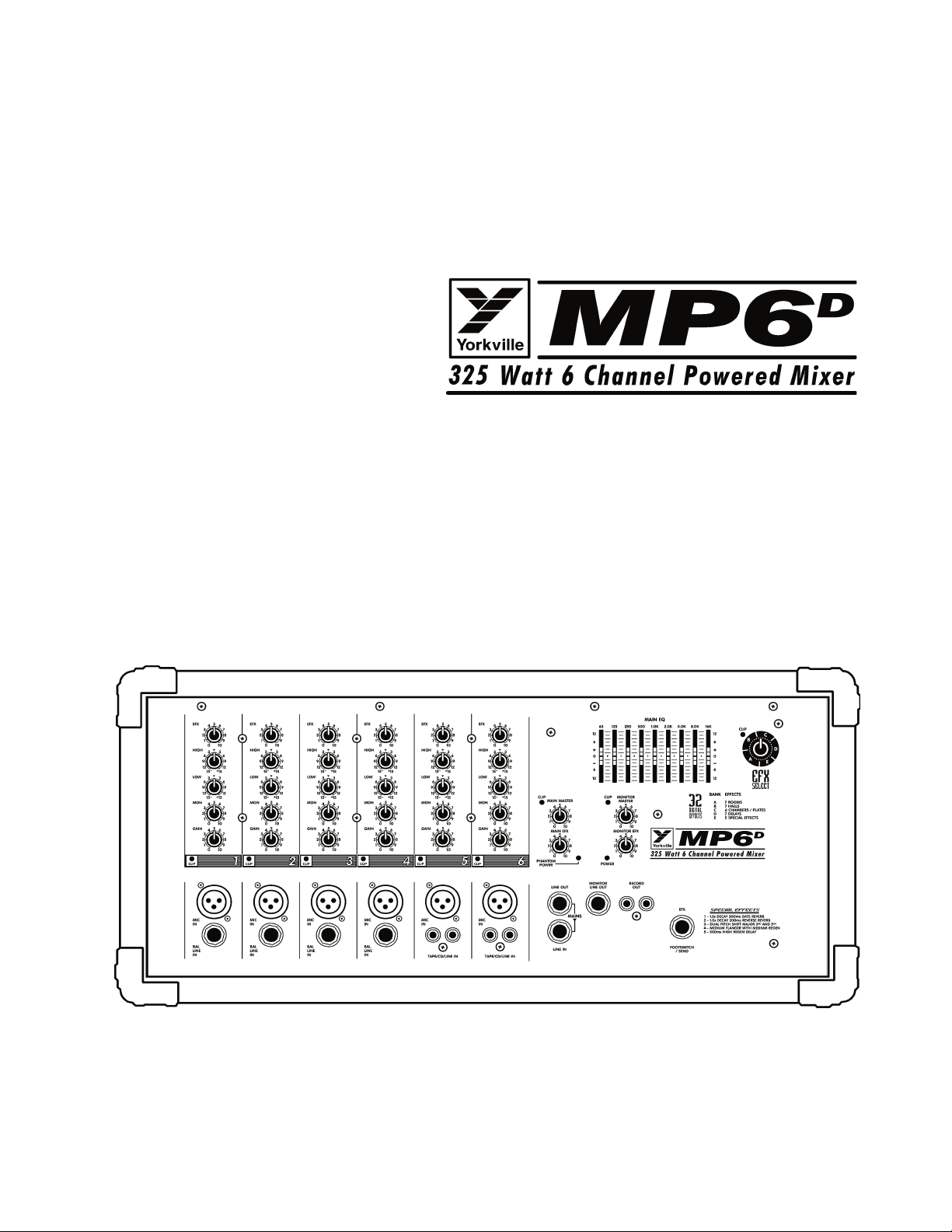
MP6D Introduction
We have coupled our extensive experience in the development and production of powered mixers, (with state of the art, computer assisted design technology) to create the smallest, lightest, and most powerful combination mixer/amplifiers available. We at Yorkville Sound are confident that you will find your new MP6D to be an efficient and versatile solution to your mixer needs. This manual contains information to help you get the maximum performance from your MP6D. We hope you'll take the time to read it.
Input Channels
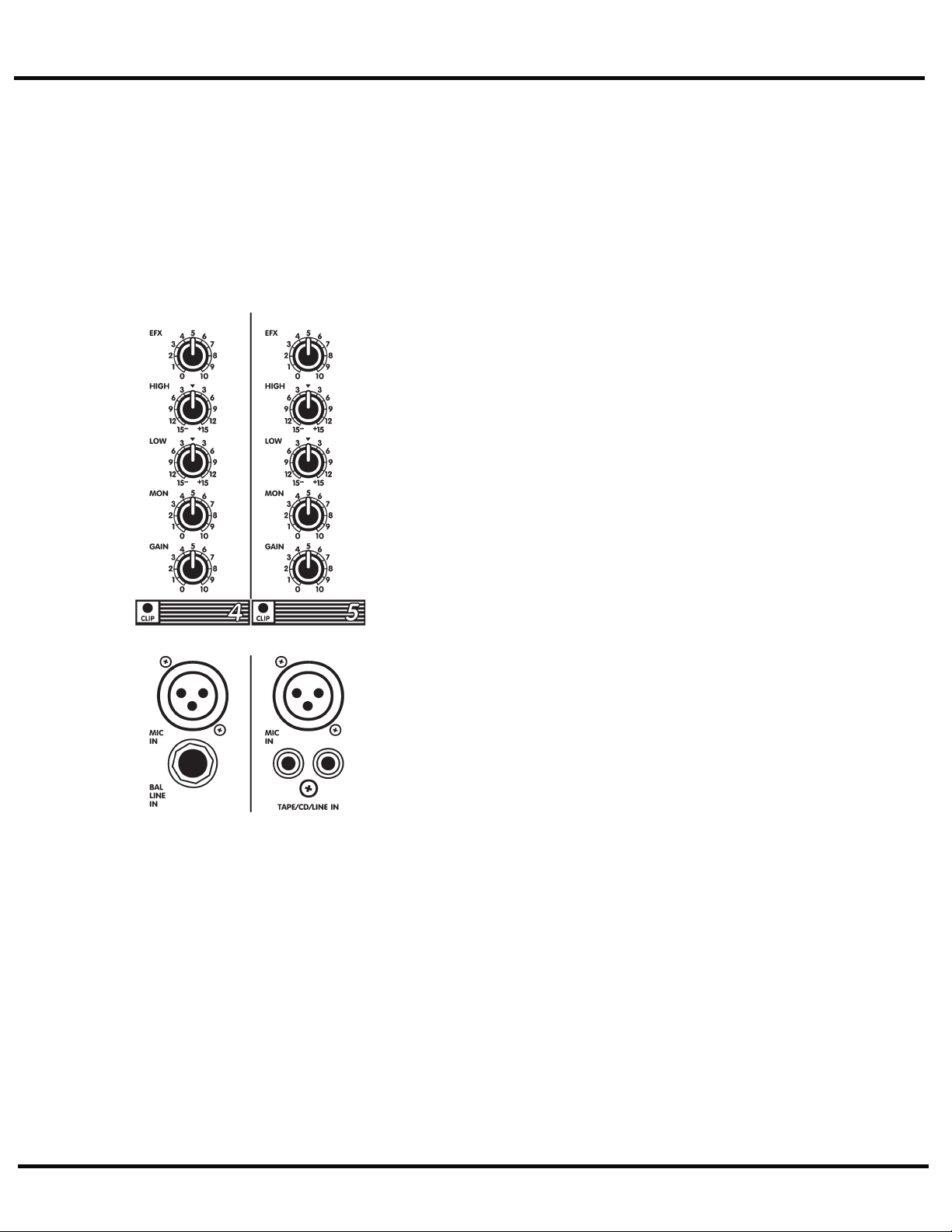
1. Microphone & Line Inputs
The MP6D features standard XLR type low-impedance Mic In connectors on
all 6 channels. These microphone inputs are electronically balanced for maximum noise suppression and have characteristics matching all low impedance
dynamic microphones. 24 Volt DC phantom power is activated via the backpanel Phantom push-button, this enables the MP6D to use condenser microphones. (Note: condenser and dynamic mics may be used together with the
Phantom power activated. It will not affect the performance of the dynamic
mics). Additionally, there are high-impedance 1/4-inch Bal Line In jacks on
channels 1 to 6. These are electronically balanced line-level inputs, but will
accept either balanced, or unbalanced input cables from high impedance
microphones, guitars, amplifier Line outputs, synthesizers, electric pianos,
etc. (Note: when connecting a balanced signal, employ balanced patch cables
with a ring-tip-sleeve (stereo) 1/4-inch plug on the mixer end). Channels 5
and 6 have dual Tape/CD/Line RCA-type inputs, (a phono preamplifier must
be connected to the MP6D inputs for optimum turntable performance).
Do not connect signals to both types of inputs on any one channel (e.g.
the Mic and Line In's on channels 1 to 4 or the Mic and Tape/CD/Line In's
on channels 5 and 6). To do so will cause improper operation of the input
circuit. (Note: you may connect a stereo source to channels 1 through 4 but
you must use two channels, one for left and one for right).
2. Channel Gain Controls & Clip LEDs
The Gain control has a range of 40dB. This adjustment determines both the
input sensitivity of the channel and the signal level sent to the Main mixing bus*. (The MP6D's channel circuitry does not require separate gain and
level controls). The Clip LED is set to illuminate when the channel's overall
signal level is 3dB below the onset of actual clipping distortion. As a result,
small amounts of LED activity are acceptable; however, frequent or continuous activity indicates the need to turn down the Gain control.
In audio terminology, a bus is a mix-down channel where all the signals
from the input channels are blended into one signal. The MP6D has three
busses, Main, Monitor and Effects.
3. Channel Low & High Equalization
The MP6D's Low and High EQ controls independently adjust the bass and treble frequencies
for each channel. The gain range for each control is plus or minus (+/-) 15dB to provide versatile equalization consistent with the clean simplicity of the MP6D's design. As with all equalizers, boosts at one or more frequencies increase the channel's signal level. If the channel is
already at a fairly high operating level, this may cause clipping in which case the Clip LED will
light. Reduce the Gain setting and/or the EQ boosts if Clip activity is excessive.
Note: Center position reflects a neutral or flat EQ control setting; however, lower EQ control settings may
be effectively employed to reduce feedback and/or distortion).
1

MICROMIX
MICROMIX
4. Channel Mon Control
Each channel has a Mon (monitor send) control which varies the amount
of channel signal being tapped off and sent to the monitor bus in the
MP6D. The Mon signal is pre-fader and pre-EQ, in other words it is taken
before the Gain and EQ controls so that the main mix can be EQ'd independently of the monitor mix. As a result, channel EQ settings do not
affect the sound of the monitor signals, nor do the channel Gain controls
regulate their volume. (Note: with an independent monitor mix, it may
be beneficial to connect a graphic equalizer to the Monitor output for
feedback control. Also, remember that to turn a channel off completely,
you must turn off both the Gain and Mon controls).
5. Channel EFX Control
Each channel has an EFX (effects send) control which adjusts the level
of the channel signal being tapped off and sent to the MP6D effects bus.
This signal is post-fader and post-EQ; in other words both the channel
EQ controls and the channel Gain control affect it. Normally, the output signal from the effects bus is internally routed to the Digital Effects
Processor. In this situation, the EFX control would regulate the intensity
of the built-in effects as it is heard on that channel's sound through the
main PA system and the Record Out jacks. In standard operating mode
with the built-in effects working, you would connect a regular on/off
footswitch (e.g. Yorkville model IFS-1A) to the EFX Footswitch/Send jack to turn the internal
effects on and off. See the section on this feature later in the manual for more information.
Alternatively, this signal can be connected to the input of an external effects unit and returned
via channel to any channel. If the effects unit uses 1/4-inch plugs, you would connect the
output of the unit to any one of the Balanced Line In jacks. In this mode, the internal effect
is not bypassed, so if you are not planning to use an internal effect, you must turn down the
Main Effects and Monitor Effects Master controls. Also, if you do not require any effects at all,
the effects bus output signal can be connected to the input of an additional monitor system or
other amp/speaker system via the EFX Footswitch/Send jack using a standard shielded patch
cord. In this case, the EFX controls would act as send controls to achieve a semi-separate mix
(remember the channel Gain controls will also affect this signal).
Master Section
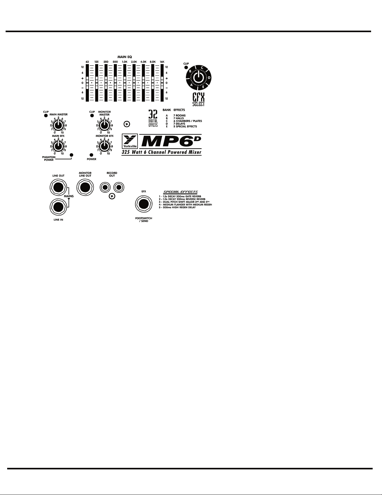
1. Main Master Control & Clip LED
The Main Master control adjusts the overall level of the main mix and the PA volume. Beside
this control is a Clip LED that indicates high signal levels within the main mixing bus. Reduce
the Main Master or the channel Gain settings if the Main Clip LED is more than slightly active.
(Note: to ensure maximum signal headroom and clarity, operate the mixer with the Main
Master set at around 7 or so. This way, you will be running the channel Gain controls at lower
settings, which helps to ensure that the channels do not clip).
2. Monitor Master Control
The overall level of the monitor mix is adjusted with the Monitor Master control. Beside it is a Clip
LED that indicates high signal levels within this bus. Reduce the Monitor Master or the channel Mon
levels if the Monitor Clip LED is more than slightly active. (Note: as with the Main Master, keep the
Monitor Master at a relatively high setting to prevent clipping the bus).
3. Main Effects Master Control
The Main EFX master control regulates the amount of signal going from the output of the internal Digital Effects Processor to the Main mixing bus where it is mixed with the dry signals
direct from the channels. It controls overall effects intensity on the Main Line Out signal and
Record Out signal, as well through the main PA speakers.
4. Monitor Effects Master
The Monitor EFX master control regulates the amount of signal going from the output of the
internal Digital Effects Processor to the Monitor mixing bus where it is mixed with the dry
signals direct from the channel Mon send controls. It controls overall effects intensity of the
Monitor Line Out signal.
2
MICROMIX
MICROMIX
5. Main Line Out
This jack can serve a variety of patching and
routing purposes. It positioned in the signal path
after the MP6D's main graphic equalizer and is
therefore affected by it (i.e. they are post-EQ).
The main bus signals are available at line level
(not speaker level; use the Speaker outputs on
the back panel to drive speakers) from the Line
Out jack. Taking a signal from this jack has no
effect on the operation of the MP6D's built-in
power amplifiers. It is, therefore, possible to feed
an external power amplifier or even several interconnected power amps, with the Main output
signal, while the internal power amplifier is also
functioning (although, it is not necessary to have
speakers connected e.g. if you want to use the
MP6D strictly as a mixer).
The Line In jack is a direct input to the built-
in power amplifier. This is a switching jack, and
when you plug into the Line In, you interrupt the
internal flow of signals going from the outputs
of the main mixing bus to the inputs of the built-
in power amp. This allows you to insert a signal
control device such as a speaker processor, an
additional equalizer, or a compressor/limiter into
the Main signal path. This is accomplished by
connecting a patch cable from the Line Out jack
to the device's input jack and another patch cable
from the device's output jack to the MP6D's Line
In jack. If you are using an external power amp
for the main PA speakers, you may run a short
patch cable from the Monitor Line Out jack to the Line In jack and simply connect your moni-
tor speakers to the MP6D's Speaker outputs on the back panel. It is even possible to connect
another mixer to the MP6D's power amplifier via the Line In jack. This slaves the amplifier to
that mixer's signals (i.e. it no longer receives the built-in mixer's signals), which means that you
could use the built-in mixer to do another, totally separate, mixing job. For example, you could
patch the MP6D's Line Out signal to an input on another mixer connected to amps driving a PA
speaker system while using the MP6D's amplifier to power control room speakers.
6. Monitor Line Out Jack
The monitor bus output signal is available at line level (not speaker level) from the Monitor
Line Out jack and would normally be patched to the input of a mono power amplifier, or
one channel of a stereo amp driving monitor speakers. Keeping in mind that there is no internal equalization for the monitor mix, you might want to patch a graphic equalizer between
the Monitor Line Out jack and the input of your monitor power amplifier to help regulate
feedback. As mentioned under the previous section, the monitor mix signal can alternately
be patched to the internal amplifiers via the Line In jack. Ask your dealer about the Yorkville
Beta-150EQ power amplifier, it has a built-in graphic equalizer.
Patching something between things, in this case, means connecting the MP6D's Monitor
Line Out jack to the input of an EQ and the output of the EQ to the input of a monitor
power amp or the Line In jack.
7. Record Out Jacks
These phono connectors carry the pre-EQ (not affected by the Main EQ) main mix signals. Record
Out signal levels are not regulated by the Main master. This allows the level to the speakers to be
reduced without lowering the levels to the Record Out jacks. Using phono-to-phono patch cords,
connect the Record Out jacks to the Aux. (line-level) inputs on the tape deck. Actual recording
levels would now be adjusted using the tape deck's record level control/s.
3
MICROMIX
MICROMIX
8. EFX Footswitch/Send Jack
This jack may be used to connect a standard on/off footswitch for the internal Digital Effects
Processor or alternately, as an effects send jack. In this latter function, it would send the signal so that
you could connect an external effects unit. If it is stereo, you would connect the unit's left and right
outputs to the dual RCA inputs on channel 5 or 6
(please note that the channel inputs are not in stereo
and that the stereo effect would be summed into a
mono mix). Here you would need to keep the Gain
level of that channel fairly low and make sure that its
EFX control is turned off. If the effects unit uses 1/4-
inch plugs, you could connect the output of the unit
to any one of the Balanced Line In jacks. As another
alternative, the EFX Footswitch/Send jack may be
used to deliver line-level signal to the input of an
auxiliary amp/speaker system, or a tape deck. Here,
the channel EFX controls would act as secondary level controls. Also keep in mind the channel EFX
send controls are post-Gain, so changes in the Gain settings will affect these levels as well.
9. Power LED & Switch
The Power LED lets you know that the MP6D is plugged in and turned on. The AC power on/
off switch is on the rear panel of the unit.
10. Phantom Power
The Phantom power LED indicates that 24 volts of DC phantom power is present on all the
XLR microphone inputs to power condenser microphones. Regular dynamic mics may be con-
nected while the Phantom Power is activated without encountering problems. The Phantom
Power push-button is located on the rear panel.
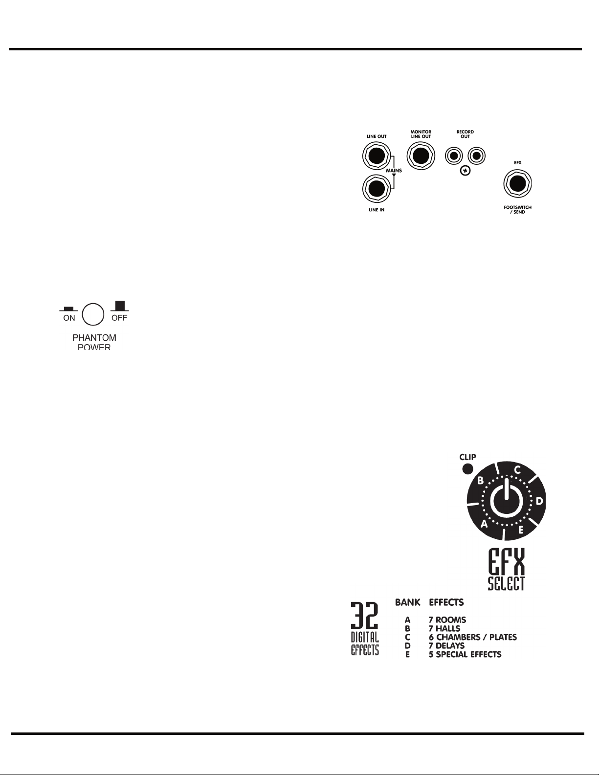
Digital Effects Processor
Digital Effects Processor Select Control
The Select control selects from 5 banks of reverb sounds, delays and other effects. Bank A rep-
resents room reverbs. Bank B are combined chambers/plate effects. Bank C is hall reverberation
effects. Bank D are delay effects, and finally Bank E is the special effects. Simply rotate the Select
control to the basic type of effect you prefer. This is a continuous type of control so you may simply
rotate it in either direction to reach the desired
setting. Lists of effects banks appear in this
manual and on the front panel of the MP6D.
NOTE: The signal sent from the Internal Digital
Effects Processor to the Monitor mix is independent from the Monitor Send controls on
the channels strips. The channel’s Gain control
feeds signal into the Effects bus, the channel’s
EFX control enables you to mix in the amount
of wet signal to your dry mix. Remember, the
Internal Digital Effects are heard through the
Monitor output only if the channel’s Gain control
is feeding signal into the Effects bus.
Effects Clip LED
Situated next to the Select control, the Clip
LED indicates if the digital processor is receiv-
ing an input signal which is too strong, possibly
resulting in distortion. For maximum dynamic
range, the Clip LED should flash briefly, but
only on high-energy transients such as loud
snare drum hits. If there is too much Clip activ-
ity, turn down the channel EFX controls.
Effects Tables
See last page for effects table.
4

MICROMIX
MICROMIX
Built in 9-Band Graphic Equalizer
General
This, like any graphic equalizer, represents a set of limited-range (+/-12dB) gain controls. In
this case there are nine sliders, each one operating over a one-octave portion of the overall
band of sound frequencies. Please note that equalizers can have an effect on the gain of the
main system as well as its frequency response. Once adjusted, you may need to turn down the
Main Master level if the Clip LED beside it becomes very active.
There Are 3 Main Functions for the Graphic EQ
1. To adjust the system for feedback reduction, the normal technique is to turn the main system up to the point of feedback and move the EQ sliders, one at a time, to determine which
frequency band is causing the feedback. (Remember to push them back up to center position
if they don't stop the feedback). When isolated, the offending band is then pushed down about
3 to 6 dB. Usually only 2 or 3 bands can be reduced before the feedback elimination process
begins to affect the sound quality.
2. To adjust for deficiencies in the speaker system's bass response, the most common adjustment is to boost the 63 Hz about 6 dB and the 100 Hz about 3 dB. However, use of the
graphic EQ to extend the deep bass frequency response of a speaker cabinet does use up a lot
of the available system power, so this technique should be used with caution to avoid distortion and possible speaker damage. On the other hand, in applications where it is appropriate
to sacrifice deep bass for higher overall sound output, the 63 Hz slider should be taken down
6 dB below centre. You may now increase the Main level for added volume.
3. The third use of the graphic equalizer is to adjust the sound character for artistic reasons.
Each frequency is adjusted until the sound is what the musicians feel sounds best. The best
sound system operators, however, usually strive to use a minimum of equalization for this purpose, or for boosting the bass. Instead, they use very minimal sound-shaping adjustments to
ensure that the threat of feedback and distortion will also be minimal.
5
 Loading...