


M-1610
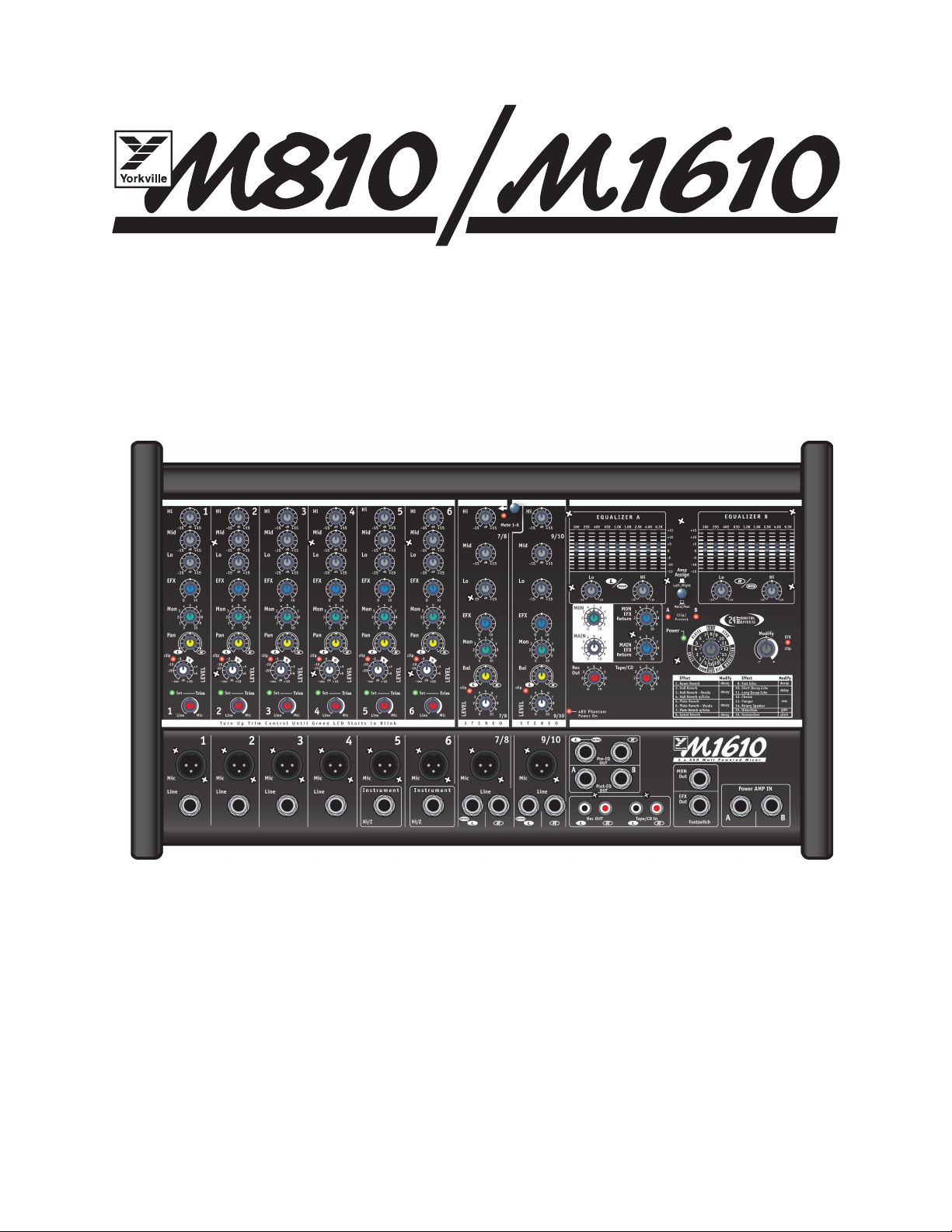
2 x 400 Watt Powered Mixer
2 x 800 Watt Powered Mixer
Series 2 Series 2
MANUEL DE L'UTILISATEUR
OWNER'S MANUAL
Powered Wedge Mixers
TYPE: YS1033 (M810-2)
TYPE: YS1032 (M1610-2)
The exclamation point within an equilatereal
triangle is intended to alert the user to the
presence of important operating and
maintenance (servicing) instructions in the
literature accompanying the appliance.
Le point d’exclamation à l’intérieur d’un triangle équilatéral
est prévu pour alerter l’utilisateur de la présence
d’instructions importantes dans la littérature accompag-
nant l’appareil en ce qui concerne l’opération et la
maintenance de cet appareil.
This lightning flash with arrowhead symbol,
within an equilateral triangle, is intended to alert
the user to the presence of uninsulated
“dangerous voltage” within the product’s enclosure
that may be of sufficient magnitude to constitute a risk of
electric shock to persons.
Ce symbole d’éclair avec tête de flèche dans un triangle
équilatéral est prévu pour alerter l’utilisateur de la présence
d’un « voltage dangereux » non-isolé à proximité de l’enceinte
du produit qui pourrait être d’ampleur suffisante pour présenter
un risque de choque électrique.
IMPORTANT SAFETY INSTRUCTIONS
safety-4v5.eps • April 3/2007
CAUTION
: TO REDUCE THE RISK OF ELECTRIC
SHOCK, DO NOT REMOVE COVER (OR BACK).
NO USER SERVICEABLE PARTS INSIDE.
REFER SERVICING TO QUALIFIED
SERVICE PERSONNEL.
FOLLOW ALL INSTRUCTIONS SUIVEZ TOUTES LES INSTRUCTIONS
Instructions pertaining to a risk of fire,
electric shock, or injury to a person
Read Instructions:
The Owner’s Manual should be read and
understood before operation of your unit. Please, save these instruc-
tions for future reference and heed all warnings.
Clean only with dry cloth.
Packaging: Keep the box and packaging materials, in case the unit
needs to be returned for service.
Warning: To reduce the risk or fire or electric shock, do not expose
this apparatus to rain or moisture.
Do not use this apparatus near water!
Warning: When using electric products, basic precautions should
always be followed, including the following:
Power Sources
Your unit should be connected to a power source only of the voltage specified in the
owners manual or as marked on the unit. This unit has a polarized plug. Do not use
with an extension cord or receptacle unless the plug can be fully inserted. Precau-
tions should be taken so that the grounding scheme on the unit is not defeated.
Hazards
Do not place this product on an unstable cart, stand, tripod, bracket or table. The
product may fall, causing serious personal injury and serious damage to the product.
Use only with cart, stand, tripod, bracket, or table recommended by the manufacturer
or sold with the product. Follow the manufacturer’s instructions when installing the
product and use mounting accessories recommended by the manufacturer.
The apparatus should not be exposed to dripping or splashing water; no objects
filled with liquids should be placed on the apparatus.
Te rminals marked with the “lightning bolt” are hazardous live; the external wiring
connected to these terminals require installation by an instructed person or the use of
ready made leads or cords.
Ensure that proper ventilation is provided around the appliance. Do not install near
any heat sources such as radiators, heat registers, stoves, or other apparatus
(including amplifiers) that produce heat.
No naked flame sources, such as lighted candles, should be placed on the apparatus.
Power Cord
Do not defeat the safety purpose of the polarized or grounding-type plug. A polarized plug
has two blades with one wider than the other. A grounding type plug has two blades and a
third grounding prong. The wide blade or the third prong are provided for your safety. If the
provided plug does not fit into your outlet, consult an electrician for replacement of the
obsolete outlet. The AC supply cord should be routed so that it is unlikely that it will be
damaged. If the AC supply cord is damaged DO NOT OPERAT E THE UNIT.
Unplug this apparatus during lightning storms or when unused for long periods of time.
Service
The unit should be serviced only by qualified service personnel.
AVIS:
AFIN DE REDUIRE LES RISQUE DE CHOC
ELECTRIQUE, N’ENLEVEZ PAS LE COUVERT (OU LE
PANNEAU ARRIERE)
NE CONTIENT AUCUNE PIECE
REPARABLE PAR L’UTILISATEUR.
CONSULTEZ UN TECHNICIEN QUALIFIE
POUR L’ENTRETIENT
Instructions relatives au risque de feu,
choc électrique, ou blessures aux personnes
Veuillez Lire le Manuel:
Il contient des informations qui devraient
êtres comprises avant l’opération de votre appareil. Conservez.
Gardez S.V. P. ces instructions pour consultations ultérieures et
observez tous les avertissements.
Nettoyez seulement avec le tissu sec.
Emballage: Conservez la boite au cas ou l’appareil devait être
retourner pour réparation.
Avertissement: Pour réduire le risque de feu ou la décharge
électrique, n'exposez pas cet appareil à la pluie ou à l'humidité.
N’utilisez pas cet appareil près de l’eau!
Attention: Lors de l’utilisation de produits électrique, assurez-vous
d’adhérer à des précautions de bases incluant celle qui suivent:
Alimentation
L’appareil ne doit être branché qu’à une source d’alimentation correspondant au
voltage spécifié dans le manuel ou tel qu’indiqué sur l’appareil. Cet appareil est
équipé d’une prise d’alimentation polarisée. Ne pas utiliser cet appareil avec un
cordon de raccordement à moins qu’il soit possible d’insérer complètement les trois
lames. Des précautions doivent êtres prises afin d’eviter que le système de mise à la
terre de l’appareil ne soit désengagé.
Risque
Ne pas placer cet appareil sur un chariot, un support, un trépied ou une table instables.
L’ appareil pourrait tomber et blesser quelqu’un ou subir des dommages importants.
Utiliser seulement un chariot, un support, un trépied ou une table recommandés par le
fabricant ou vendus avec le produit. Suivre les instructions du fabricant pour installer
l’appareil et utiliser les accessoires recommandés par le fabricant.
Il convient de ne pas placer sur l’appareil de sources de flammes nues, telles que
des bougies allumées.
L’appeil ne doit pas être exposé à des égouttements d’eau ou des éclaboussures
et qu’aucun objet rempli de liquide tel que des vases ne doit être placé sur l’appareil.
Assurez que lappareil est fourni de la propre ventilation. Ne procédez pas à
l’installation près de source de chaleur tels que radiateurs, registre de chaleur, fours
ou autres appareils (incluant les amplificateurs) qui produisent de la chaleur.
Les dispositifs marqués d’une symbole “d’éclair” sont des parties dangereuses
au toucher et que les câblages extérieurs connectés à ces dispositifs de
connection extérieure doivent être effectivés par un opérateur formé ou en utilisant
des cordons déjà préparés.
Cordon d’Alimentation
Ne pas enlever le dispositif de sécurité sur la prise polarisée ou la prise avec tige de
mise à la masse du cordon d’alimentation. Une prise polarisée dispose de deux
lames dont une plus large que l’autre. Une prise avec tige de mise à la masse
dispose de deux lames en plus d’une troisième tige qui connecte à la masse. La
lame plus large ou la tige de mise à la masse est prévu pour votre sécurité. La prise
murale est désuète si elle n’est pas conçue pour accepter ce type de prise avec
dispositif de sécurité. Dans ce cas, contactez un électricien pour faire remplacer la
prise murale. Évitez d’endommager le cordon d’alimentation. N’UTILISEZ PAS
L’APPAREIL si le cordon d’alimentation est endommagé.
Débranchez cet appareil durant les orages ou si inutilisé pendant de longues périodes.
Service
Consultez un technicien qualifié pour l’entretien de votre appareil.
S2125A
1
Introduction
Thank you for purchasing a Yorkville powered mixer. We at Yorkville Sound are confident
that you’ll find the M810/M1610 to be an excellent and versatile mixer/amp. We’ve
used our experience in the development of powered mixers to create the smallest,
lightest, and most powerful combination mixer/amplifiers available. This manual con-
tains information to help you get the maximum performance from your M810/M1610.
We hope you’ll take the time to read it.
Stereo Power Amplifier
The M810/M1610 features high-efficiency stereo power amplifiers which have been
designed to deliver maximum power into a 4-ohm load. When lower speaker impedances are
connected, a dedicated, sonically transparent circuit limits the output power to safe levels.
Multiple speakers may be connected without the amplifier overheating or shutting down.
Input Channels
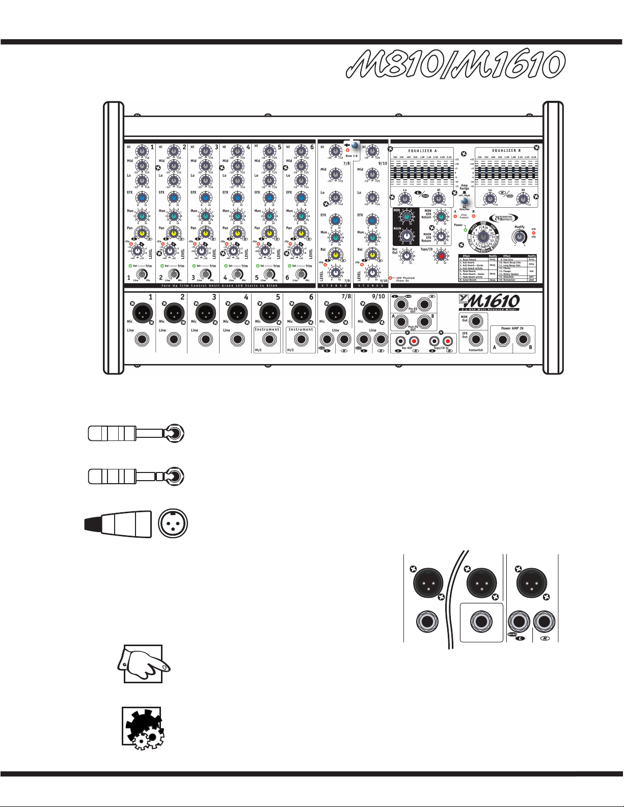
1. MIC and LINE Inputs
The M810/M1610 features gold-plated dual-
contact XLR low-impedance microphone connectors
on the channels. These microphone inputs are bal-
anced for maximum noise suppression. Condenser
microphones can also be connected. The 48 Volt
DC phantom power is activated by depressing the
Phantom Power push-button on the rear panel.
Note: Condenser and dynamic mics can
be used together while the phantom power is on. It will not affect the performance
of the dynamic mics.
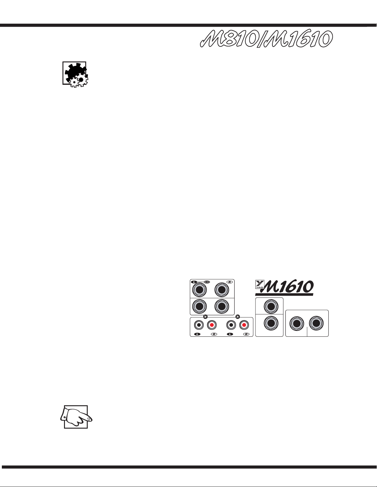
In addition to the XLR inputs, each channel features ¼-inch LINE in jacks. Channels
1-4, 7/8 and 9/10 are balanced line-level inputs and will accept either balanced (Tip/
Ring/Sleeve) or unbalanced (Tip/Sleeve) input cables from high impedance microphones,
mixer line outputs, keyboards, synthesizers, electric pianos etc.
Note: When connecting a balanced signal, use balanced patch cables with either an
XLR or a Tip/Ring/Sleeve ¼-inch plug on the mixer end.
1/4-inch Phone Plug
1/4-inch T.R.S. Phone Plug
XLR Plug
46
7/8
Instrument
Mic
Line
Mic Mic
Hi/Z
Line
2
Channels 5 and 6 have very high impedance, unbalanced ¼-inch inputs which are opti-
mized for instruments such as electric basses, acoustic electric guitars etc. Stereo chan-
nels 7/8 and 9/10 have left and right ¼-inch balanced LINE in jacks as well as mono
gold-plated XLR low impedance microphone inputs. The ¼-inch inputs may be used to
connect a stereo CD player, tape deck or an additional mixer etc. A phono pre-amplifier
must be connected to the M810/M1610 inputs for optimum turntable performance.
Connecting signals to both types of inputs on any one channel (MIC and LINE in) is
not recommended. To do so may change the gain of the input circuit.
Note: You may connect a stereo source to channels 1 through 6 but you must
use two channels, one for left and one for right and Pan appropriately or sum to
mono using a ‘Y’ cable.
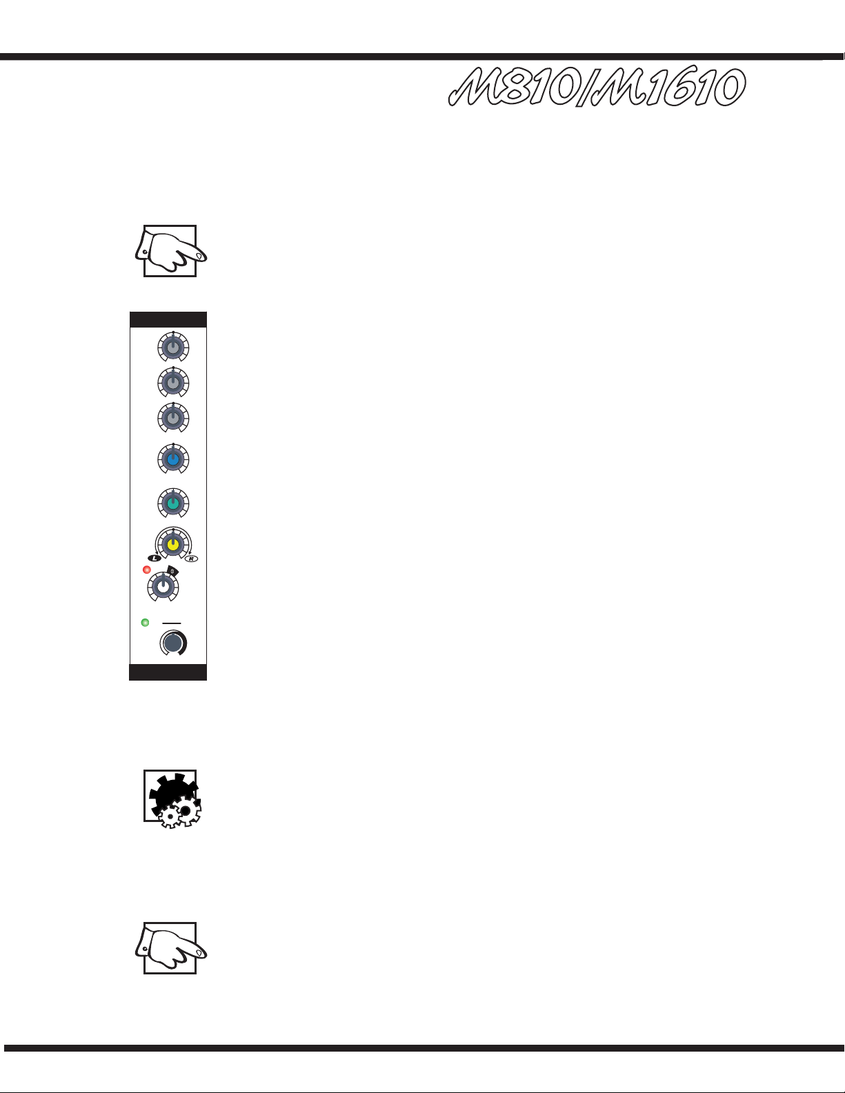
2. Channel 1-6 TRIM Controls and SET LEDs
The first 6 mono channels of the M810/M1610 have been equipped with an input TRIM
control and are also protected by an overload protection circuit. The TRIM controls are
used to make sure that an ideal signal level is flowing through the channel, no matter
what the input source. Each channel has a green LED that will flash when the proper sig-
nal level has been reached. The channel overload protection circuit will provide additional
protection from clipping on peaks of up to 16 dB above normal operating levels.
To set the TRIM
i. Turn down the channel LEVEL control,
ii. With a normal signal present at the input, turn up the TRIM control until the green
LED just starts to flash (when the signal peaks).
iii. You can then use the LEVEL control to set the channel volume level. Increasing
the TRIM beyond this point will compress the signal on that channel.
3. Channel LEVEL Controls and CLIP LEDs
This adjustment determines the signal level sent to the MAIN mixing bus. The CLIP LED
will illuminate when the channel’s overall signal level is 3 dB below the onset of actual
clipping. As a result, small amounts of clip LED activity are acceptable, however frequent
or continuous activity indicates the need to turn down the LEVEL control.
In audio terminology, a bus is a mix-down channel where all the signals from the
input channels are blended into one signal. The M810/M1610 has 5 busses: MAIN
(left and right), MONITOR, EFFECTS and RECORD OUT.
4. Channel Lo, Mid, and Hi Equalization
The M810/M1610 tone controls adjust the bass, middle and treble frequencies for each
channel independently. Center frequencies have been carefully selected to help achieve
the best quality of sound. Bass is centered on 40 Hz, Mid at 700 Hz and the Hi is at
12 kHz. The adjustment range for each control is +/- 15 dB. These parameters provide
versatile equalization consistent with the clean simplicity of the M810/M1610’s design.
As with equalizers, boosting one or more frequencies increase the channel’s level. If the
channel is already at a high level, clipping may occur, in which case the clip LED will
illuminate. Reduce the LEVEL setting and/or the Equalizer if clip activity is excessive.
Note: The center position reflects a neutral or flat EQ control setting; however, turn-
ing down EQ settings can be used effectively to reduce feedback and/or distortion).
5. Channel MON Controls
The MON control (monitor send) on each channel varies the amount of signal being sent to
the monitor bus in the M810/M1610. In the mono channels the MON signal is pre-LEVEL
control, post-EQ and post-TRIM. It is taken before the LEVEL control so the monitor signal
can be mixed independently of the MAIN mix. As a result, channel EQ and TRIM settings do
affect the sound of the monitor signals, while the channel LEVEL controls do not affect the
MON signal. The MON signal in the stereo channels is pre-LEVEL and pre-EQ.
Note: With an independent monitor mix, it may be beneficial to connect a graphic
equalizer between the MON output and the monitor amplifier (Power AMP IN B,
external amplifier or powered speakers, depending on how you have it set up) to
help control feedback.
-3
-20
+6
+3
0
-10
+10
0
0
-
1
Set
LEVEL
Trim
dB
Line Mic
0
10
-15 +15
dB
-15 +15
dB
-15 +15
dB
0
5
28
7
6
4
3
91
10
clip
Pan
Mon
EFX
Lo
Mid
Hi
1
3
6. Channel EFX Controls
The EFX control (effects send) for each channel adjusts the level of the channel signal
being sent to the M810/M1610 effects bus. This signal is post-LEVEL control and post-EQ,
the sound is affected by both the channel EQ controls and the channel LEVEL control. The
signal from the effects bus is internally routed to the Digital Effects Processor. The chan-
nel EFX control regulates the intensity of the built-in digital effects for the channel’s out-
put. When using the built-in digital effects, you can connect a standard on/off footswitch
(e.g. Yorkville model IFS-1A) to the EFX Out/Footswitch jack to turn the internal effects
on or off. For more information see the section EFX Out/Footswitch in this manual.
Tip: Alternatively, this signal at this jack can be connected to the input of an exter-
nal stereo effects unit and returned via channel 7/8 or 9/10. However, if you do not
require any effects at all, the effects bus output signal can be connected to the
input of an additional monitor system or another amp/speaker system via the EFX
Out/Footswitch jack using a standard balanced patch cord. In this case, the EFX
controls would act as send controls to achieve a semi-separate mix. Remember
that the channel LEVEL controls also affect this signal.
7. Channel Pan and Bal Controls
The signal balance of each channel going to the left and right main PA channels can be
adjusted by the Pan control in channels 1 to 6, and by the Bal control in channels 7/8
and 9/10. Turning this control counterclockwise towards the L will increase the signal
level in the left channel to a maximum of 3 dB while also reducing the level in the right
channel to zero. Turning the control clockwise towards the R will increase the signal level
in the right channel while also reducing the signal level in the left channel.
Master Section
1. MAIN Master Control
The MAIN master control adjusts the over-
all level of the main mix, the PA volume.
Note: To ensure maximum signal head-
room and clarity, set the channel TRIM
and LEVEL controls first for a good sig-
nal without clipping, then set the master
for the overall volume desired.
2. MON Master Control
The overall level of the monitor mix is
adjusted with the MON master control.
Note: As with the MAIN master,
set the MON master to deliver the
desired volume after setting the
channel sends.
3. MAIN EFFECTS Return Control
The MAIN EFX control regulates the amount of signal going from the output of the inter-
nal Digital Effects Processor to the MAIN mixing bus where it is mixed with the dry signals
directly. It controls the intensity of the effects on the left and right MAIN output signals.
4. MON EFFECTS Return Control
The MON EFX control regulates the amount of signal going from the output of the
internal Digital Effects Processor to the MON mixing bus where it is mixed with the dry
signals directly from the channel MON send controls. It controls the overall effects
intensity for the MON Out signal.
5. Pre-EQ OUT, Post-EQ OUT
These jacks offer a variety of patching and routing options. They are positioned in the
signal path before and after the M810/M1610 main graphic equalizers.
These bus signals are at line level, not speaker level (use the SPEAKER outputs on
the rear panel to drive speakers). Using signals from these jacks has no effect on the
operation of the M810/M1610 built-in power amplifier. This makes it possible to feed
an external power amplifier, or even multiple inter-connected power amps, while the
internal power amplifier is functioning.
4
Note: It is not necessary to have speakers connected if you’d like to use the unit
strictly as a mixer. If a mono signal is required, possibly to feed a mono-house PA or
another amp/speaker system, use the L/Mono Pre-EQ jack. Mono operation of this
jack is switched to left channel only as soon as a jack is inserted in the R Pre-EQ
jack. The Post-EQ OUT jacks are not linked in this manner. They follow the operation
of the Main/Mon switch described below.
6. Power AMP IN Jacks
The Power AMP A IN and Power AMP B IN jacks are direct inputs to the built-in power ampli-
fiers. They are referred to as A and B rather than left and right simply because it is possible
to power both main PA speakers with one amplifier channel and monitors with the other.
This can be accomplished by selecting the Main/Mon position on the selector switch located
between the graphic equalizers. In the Left/Right position, Power AMP A receives the left
signal while Power AMP B receives the right signal. In the Main/Mon position, Power AMP A
receives a mono sum of left and right signals while Power AMP B receives the monitor signal.
An alternative use for the Power AMP A IN and Power AMP B IN jacks would be as patching
inputs. Since they’re switching jacks if you plug into one (or both) the internal signal flow
will be interrupted. This interrupts the signal from the M810/M1610 mixer to the built-in
power amplifiers allowing you to insert signal control devices such as an élite processor, an
additional equalizer, or a compressor/limiter into the main stereo signal path. Connect cables
from the L and R Post-EQ OUT (or Pre-EQ OUT) to the device’s input jacks and then from the
device’s output jacks to the M810/M1610 Power AMP A IN and Power AMP B IN jacks.
You can connect another mixer to the M810/M1610 power amplifier through the Power AMP
A IN and Power AMP B IN jacks. This slaves the amplifier to the other mixer’s signals; it no
longer receives the built-in mixer’s signals which means that you could use the built-in mixer to
do a totally separate mixing job. For example, you could patch the M810/M1610 L and R Pre-
EQ OUT (or Post-EQ OUT) to inputs on another mixer connected to other amplifiers driving a PA
speaker system while using the M810/M1610’s A and B amps to power control room speakers.
7. Rec OUT Jacks
These phono connectors send the L and R pre-EQ, pre-EFFECTS (not affected by the
MAIN EQ) main mix signals. The Rec OUT control, located just below the MAIN control,
adjusts the signal level for these jacks. Using phono patch cords, connect directly to the
Auxiliary (line-level) inputs on a tape deck or other recording device.
8. MON Out Jack
The monitor bus output signal
from the Mon OUT jack is line
level and would normally be
patched to the input of a mono
power amplifier (or a single
channel of a stereo amp) driving
stage monitor speakers. Keep
in mind that in the Left/Right
position of the Amp Assign
switch there is no internal equal-
ization for the monitor mix (you might want to patch a graphic equalizer between the Mon OUT
jack and the input of your monitor power amplifier, this can help regulate the feed). As men-
tioned under #5. Pre-EQ OUT, Post-EQ OUT section (above), the monitor mix signal can also be
patched to one channel of the internal amplifier using the Amp Assign switch.
9. EFX Out / Footswitch Jack
Using this jack you can connect a standard on/off footswitch to control the activation of
the internal Digital Effects Processor or it can be used as an effects send jack for use with
an external effects processor.
Note: Both devices would be sent a signal, so you could connect the external unit’s
left and right outputs to the L and R inputs on channel 7/8 (channel 9/10 or any of
the other channels). Use the LEVEL of that channel to adjust the amount of wet
signal added to the main mix and the MON control to adjust the amount of wet sig-
nal added to the monitor mix. Make sure that its EFX control on the channels are
turned off. An alternative could be to use the EFX Out / Footswitch jack to deliver
line level signal to the input of an auxiliary amplifier or even a recording device.
Here, the channel EFX controls would act as secondary level controls.
A
A
B
B
Pre-EQ
OUT
Post-EQ
OUT
Rec OUT Ta pe/CD In
Footswitch
Power AMP IN
MON
Out
EFX
Out
2 x 800 Watt Powered Mixer
5
10. Power LED and Switch
The Power LED lets you know that the M810/M1610 is plugged in, turned on and all
systems are normal. The Clip/Protect LEDs normally indicate clipping in the amplifiers.
They will remain illuminated and the power LED will turn off in the unlikely event that
the amplifiers overheat or if DC voltage is detected on the output. The AC power on/off
switch is on the rear panel of the M810/M1610.
11. Phantom Power
The Phantom Power LED indicates that 48 volts of DC phantom power is present on
the XLR microphone inputs for powering condenser microphones. Regular dynamic mics
may also be used while the Phantom Power is on. Connecting a microphone of either
type with phantom power on and the channel LEVEL up will create a large transient,
resulting in a loud, potentially damaging pop. When setting up, either turn off the AC
power, the phantom power, or set all channel levels to zero. The Phantom Power push-
button is located on the rear panel between the speaker output jacks.
12. Tape/CD Input
Left and right RCA inputs are provided to connect a CD player, cassette player or other
stereo source to the mixer. These inputs are routed directly to the main bus, the Tape/CD
control adjusts the amount of signal.
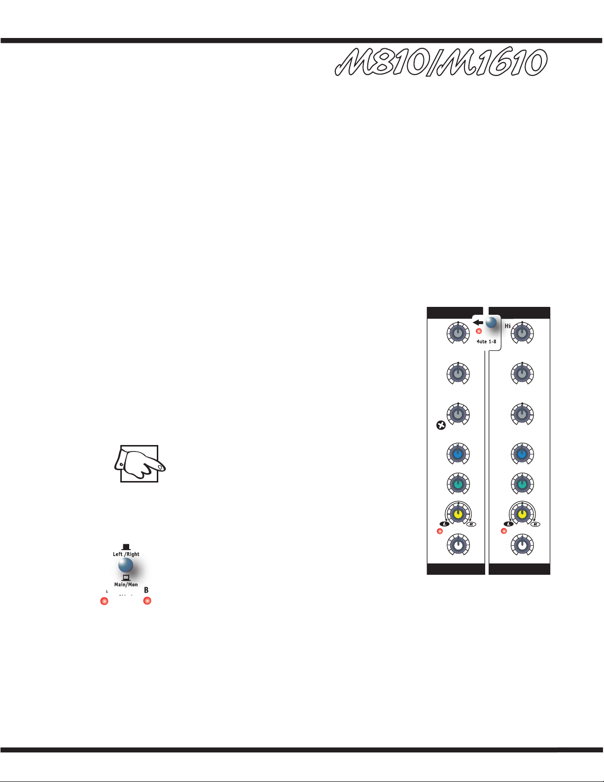
13. Mute 1-8 Switch
The M810/M1610 includes a feature that enables users
to instantly mute channels 1-8. Depressing the Mute 1-8
switch will mute channels 1-8 signals being sent to the
Left, Right, Mon and EFX busses (the signals from these
channels will still be sent to the record bus and will not
be muted. Channel 9/10 will remain active, leaving this
channel open for allowing a microphone or CD player, cas-
sette player or other stereo source to be heard over the
Left, Right, Mon and EFX busses. This feature lets you
mute the mics and instruments on stage and still allows
you to make announcements or play music during breaks.
When the band returns to perform, simply deactivate.
Note: The Tape/CD input in the master section also
remains active. While muted, the Mute LED flashes
at a slow rate (long on/short off) and the clip LEDs
of all the muted channels alternate long off/short on.
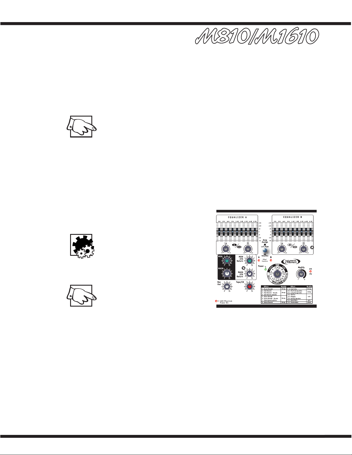
14. Amp Assign Switch
The MAIN controls determine the level of the signal
routed through the Amp Assign switch:
i. In the Left/Right position, the Amp Assign
switch directs the left and right MAIN master
signals through Equalizer A and Equalizer B. The
signal goes to the left and right inputs of the
built-in power amplifier (Amp A and Amp B) and
to the left and right post-EQ OUT jacks.
ii. In the Main/Mon position, the Amp Assign switch sums the left and right MAIN
signals into a single, mono signal while directing it to the input of Equalizer
A, the output of which goes to both the Amp A power amp channel and to the
Post-EQ MAIN OUT jack. Additionally, the signal from the MON master’s output
is routed through Equalizer B and then to both the Amp B power amp channel
and to the MON Out jack.
Mute 1-8
0
10
0
10
0
5
28
7
6
4
3
91
10
0
5
28
7
6
4
3
91
10
0
5
28
7
6
4
3
91
10 0
5
28
7
6
4
3
91
10
-15 +15
dB
-15 +15
dB
-15 +15
dB
-15 +15
dB
-15 +15
dB
-15 +15
dB
clip clip
9/10
7/8
7/8
9/10
Bal
Mon
EFX
Lo
Mid
Hi
Bal
Mon
EFX
Lo
Mid
Hi
LEVEL
LEVEL
STEREO STEREO
Main/Mon
Left /Right
AB
Amp
Assign
Clip/
Protect
6
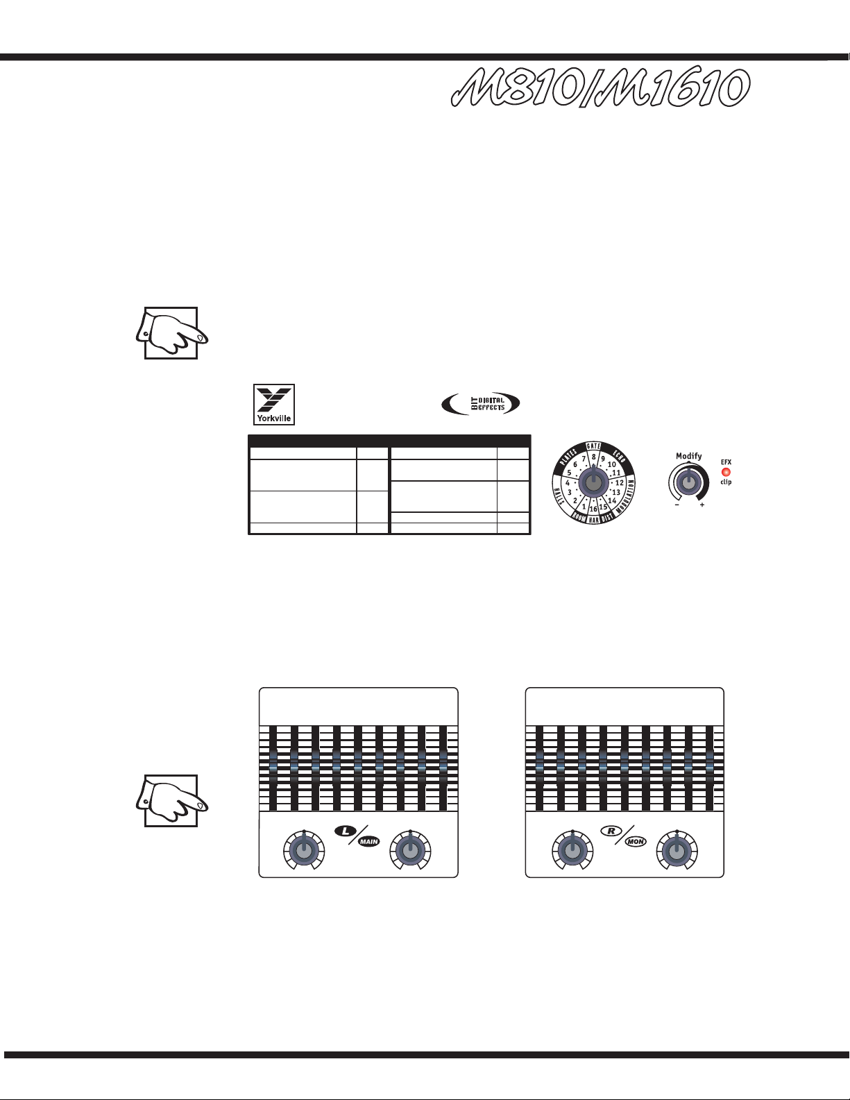
Digital Effects Processor
1. Select and MODIFY EFX Controls
Use the EFX Selection control to choose from the sixteen 24-bit digital reverbs, delays
and other effects. This control ro-tates continuously, which lets you rotate clockwise or
counter-clockwise to select the desired effect. For convenience, a table of the effects and
their variables appear later in this manual and on the front panel of the M810/M1610.
Parameters for each of the effects can be changed using the MODIFY control which is
located next to the Selection control. For example, if a Hall reverb has been selected,
the MODIFY control will let you adjust the decay parameter. Choosing the Chorus effect
allows the chorus rate to be adjusted.
Note: The signal sent from the internal Digital Effects Processor to the MON mix is
independent from the MON send controls on the channel strips. When a channel’s
EFX control routes a signal to the internal Effects processor and the MON level con-
trol (for that channel) is turned off, the channel’s wet effects will still be audiable in
the monitor bus (if the EFX to MONitor return level is turned up).
2. Effects CLIP LED
Situated to the right of the MODIFY EFX control, the CLIP LED indicates that the digi-
tal processor is receiving an input signal that’s too strong, resulting in distortion. For
optimum performance, the CLIP LED should never flash. If there is clipping activity, turn
down the channel EFX controls appropriately.
Built in 9-Band Graphic Equalizer & Shelving EQs
1. General
Each EQ consists of a set of +/-15dB range type controls. In the M810/M1610 there are
nine sliders for each channel, each one operating over a 2/3-octave portion of the mid-
range band of sound frequencies, as well as rotary shelving Bass and Treble controls.
Note: Equalizers have an effect on the gain of the main system as well as its fre-
quency response. Once adjusted, you may need to adjust the MAIN master level if
the clip LEDs become too active.
M810/M1610
Series 2
Room Reverb
Hall Reverb
Hall Reverb - Vocals
Hall Reverb w/Echo
Plate Reverb
Plate Reverb - Vocals
Plate Reverb w/Echo
Gated Reverb
decay
decay
decay
decay
ModifyEffect
decay
gain
pitch
delay
rate
1.
2.
3.
4.
5.
6.
7.
8.
9.
10.
11.
12.
13.
14.
15.
16.
Fast Echo
Short Decay Echo
Long Decay Echo
Chorus
Flanger
Rotary Speaker
Distortion
Harmonizer
ModifyEffect
24
EQUALIZER A
EQUALIZER B
+15
+10
+5
0
-5
-10
-15
+15
+10
+5
0
-5
-10
-15
160 250 400 630 1.0K 1.6K 2.5K 4.0K 6.3K 160 250 400 630 1.0K 1.6K 2.5K 4.0K 6.3K
-15 +15 -15 +15 -15 +15 -15 +15
Lo Hi Lo Hi
7
2 Main Functions for the Graphic EQ and Shelving Equalizers
i. To adjust the system to help reduce feedback, a normal technique is to turn the
main system up to the point of feedback and then adjust the EQ sliders individual-
ly to determine which frequency band will reduce the potential of feedback. When
the specific frequency band is isolated, set it to about -3 to -5 dB. Usually only 2
or 3 bands can be reduced before the feedback reduction process begins to affect
the sound quality.
ii. To adjust for deficiencies in the speaker system’s high frequency and bass response,
the M810/M1610 also has a 2-band rotary shelving equalizer. These work in conjunc-
tion with the 9-band graphic. Yorkville engineers have developed this technique to
provide you with greater tone shaping capability. This allows the graphic equalizer
bands frequencies to be spaced at closer intervals, which mean better selectivity for
feedback reduction and sound shaping. You may want to turn up the Lo and Hi con-
trols to give the system a more HiFi sound when you’re playing at lower volumes. At
higher volume levels, you may need to turn these controls down, this will help maxi-
mize the volume and tighten up the sound.
iii. The third use of the graphic equalizer is to adjust the sound character for artistic
reasons. The frequencies are adjusted until the sound feels best to the musicians.
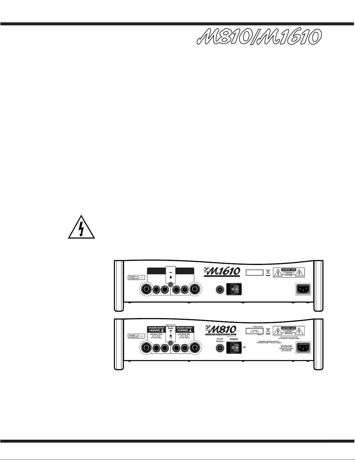
M810/M1610 Rear Panel
1. Power Amplifiers
Each of the M810/M1610 dual power amplifiers has two ¼-inch jacks and 1 Speakon
jack for speaker connections. The power amplifiers are designed to provide full power into
a 4-ohm load. Connecting two 4-ohm speakers (2-ohm load) to either AMP A or AMP B
will not harm the M810/M1610 but the maximum power output may be reduced.
WARNING: Do not obstruct the flow of air around the vents on the rear of the
M810/M1610, this may cause the power amplifier to overheat. The amplifier will
start to reduce its power output in order to keep running. In extreme cases it may
be forced to shut down. If the clip LEDs are illuminated continuously and the Power
LED is off, this will indicate shutdown. After the M810/M1610 cools down, operation
will be restored automatically This condition should not occur if adequate ventila-
tion is provided at the back of the unit.
2. Power Switch and Breaker
The Power switch and circuit breaker are located on the rear panel. If the circuit breaker
trips during use, wait a few minutes (to cool), then push in to reset. The circuit breaker
can trip if the amplifier is too heavily loaded with long periods of continuous tones (such
as feedback). If the circuit breaker trips immediately after being reset, take the unit to
your Yorkville dealer for service.
CHANNEL
B
CHANNEL
A
SPEAKER OUTPUT SPEAKER OUTPUT
Phantom
P o we r
POWER
ON
Circuit
Breaker
DESIGNED & MANUFACTURED BY
YORKVILLE SOUND • TO RONT O, CANADA
on
of f
120V A C
60 Hz • 6.4 A
TYPE: YS1032
A-Z446A / 2.0
800 Watts MAX
@ 4 ohms
(2 ohm min.)
800 Watts MAX
@ 4 ohms
(2 ohm min.)
2 x 800 Watt Powered Mixer
Series 2
DISCONNECT POWER
BEFORE SERVICING!
DEBRANCHER L’APPEREIL
A V ANT D’ENLEVER
LES COUVERCLES!
THIS UNIT MUST BE GROUNDED!
CET APPAREIL DOIT ETRE MIS Á TERRE!
 Loading...