

Page 1

WEB ACCESS: http://www.yorkville.com
Manual-Service-nx35-1v1.pdf
WORLD HEADQUARTERS
CANADA
SERVICE MANUAL
NX35
U.S.A.
Yorkville Sound
550 Granite Court
Pickering, Ontario
L1W-3Y8 CANADA
Voice: (905) 837-8481
Fax: (905) 837-8746
Quality and Innovation Since 1963
Yorkville Sound Inc.
4625 Witmer Industrial Estate
Niagara Falls, New York
14305 USA
Voice: (716) 297-2920
Fax: (716) 297-3689
Printed in Canada
Page 2

IMPORTANT SAFETY INSTRUCTIONS
INSTRUCTIONS PERTAINING TO A
RISK OF FIRE, ELECTRIC SHOCK,
OR INJURY TO PERSONS
CAUTION:
TO REDUCE THE RISK OF ELECTRIC SHOCK, DO
NOT REMOVE COVER (OR BACK).
NO USER SERVICEABLE PARTS INSIDE.
REFER SERVICING TO QUALIFIED
SERVICE PERSONNEL.
Read Instructions
The Owner’s Manualshould be read and understood
before operation of your unit. Please, save these instructions for future reference.
Packaging
Keep the box and packaging materials, in case the unit
needs to be returned for service.
Warning
When using electric products, basic precautions should
always be followed, including the following:
Power Sources
Your unit should be connected to a power source only of the voltage
specified in the owners manual or as marked on the unit. This unit has a
polarized plug. Do not use with an extension cord or receptacle unless
the plug can be fully inserted. Precautions should be taken so that the
grounding scheme on the unit is not defeated.
Hazards
Do not place this product on an unstable cart, stand, tripod, bracket or
table. The product may fall, causing serious personal injury and serious
damage to the product. Use only with cart, stand, tripod, bracket, or
table recommended by the manufacturer or sold with the product.
Follow the manufacturer’s instructions when installing the product and
use mounting accessories recommended by the manufacturer.
The apparatus should not be exposed to dripping or splashing water;
no objects filled with liquids should be placed on the apparatus.
Terminals marked with the “lightning bolt” are hazardous live; the
external wiring connected to these terminals require installation by an
instructed person or the use of ready made leads or cords.
Ensure that proper ventilation is provided around the appliance.
No naked flame sources, such as lighted candles, should be
placed on the apparatus.
Power Cord
The AC supply cord should be routed so that it is unlikely that it will be
damaged. If the AC supply cord is damaged DO NOT OPERATE THE UNIT.
Service
The unit should be serviced only by qualified service personnel.
INSTRUCTIONS RELATIVES AU RISQUE
DE FEU, CHOC ÉLECTRIQUE, OU
BLESSURES AUX PERSONNES
AVIS:
AFIN DE REDUIRE LES RISQUE DE CHOC ELECTRIQUE,
N’ENLEVEZ PAS LE COUVERT (OU LE PANNEAU ARRIERE)
NE CONTIENT AUCUNE PIECE
REPARABLE PAR L’UTILISATEUR.
CONSULTEZ UN TECHNICIEN QUALIFIE
POUR L’ENTRETIENT
Veuillez Lire le Manuel
Il contient des informations qui devraient êtres comprises
avant l’opération de votre appareil. Conservez S.V.P. ces
instructions pour consultations ultérieures.
Emballage
Conservez la boite au cas ou l’appareil devait être
retourner pour réparation.
Attention:
Lors de l’utilisation de produits électrique, assurezvous d’adhérer à des précautions de bases incluant
celle qui suivent:
Alimentation
L’appareil ne doit être branché qu’à une source d’alimentation
correspondant au voltage spécifié dans le manuel ou tel qu’indiqué sur
l’appareil. Cet appareil est équipé d’une prise d’alimentation polarisée.
Ne pas utiliser cet appareil avec un cordon de raccordement à moins
qu’il soit possible d’insérer complètement les trois lames. Des
précautions doivent êtres prises afin d’eviter que le système de mise à
la terre de l’appareil ne soit désengagé.
Risque
Ne pas placer cet appareil sur un chariot, un support, un trépied ou une
table instables. L’appareil pourrait tomber et blesser quelqu’un ou subir
des dommages importants. Utiliser seulement un chariot, un support,
un trépied ou une table recommandés par le fabricant ou vendus avec
le produit. Suivre les instructions du fabricant pour installer l’appareil et
utiliser les accessoires recommandés par le fabricant.
Il convient de ne pas placer sur l’appareil de sources de flammes
nues, telles que des bougies allumées.
L’appeil ne doit pas être exposé à des égouttements d’eau ou des
éclaboussures et qu’aucun objet rempli de liquide tel que des vases
ne doit être placé sur l’appareil.
Assurez que lappareil est fourni de la propre ventilation.
Les dispositifs marqués d’une symbole “d’éclair” sont des parties
dangereuses au toucher et que les câblages extérieurs connectés à
ces dispositifs de connection extérieure doivent être effectivés par un
opérateur formé ou en utilisant des cordons déjà préparés.
Cordon d’Alimentation
Évitez d’endommager le cordon d’alimentation. N’UTILISEZ PAS
L’APPAREIL si le cordon d’alimentation est endommagé.
Service
Consultez un technicien qualifié pour l’entretien de votre appareil.
safety-4v3.eps • Oct. 26/05
Page 3
nx35
K
L
R
YS No. Description Qty. YS No. Description Qty.
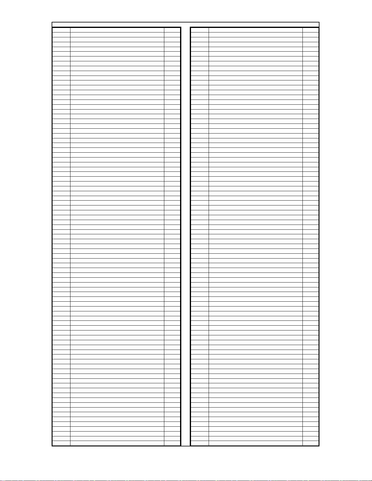
5942 _3U3 100DC 10%CAP BLK RAD POLYE FLM 3
5950 _4U7 250DC 10%CAP BLK RAD POLYP FLM 1
5944 _15U 100DC 10% CAP BLK RAD PLYE FLM 1
706 1/2"X24"X250' DURABUBBLE 5
713 25 X 20 X 50 2 MIL PLASTIC BAG 1
3784 _300UH COIL 22AWG R000 BOBBIN 1
3726 1500UH COIL 16AWG R156 IRN CORE 1
3716 2000UH COIL 22AWG R561 IRN CORE 1
8483ADAPTOR,SPEAKER STAND,METAL,BLAC
8538 RUBBER BUMPER W/ WASHER 1.375X1.375 3
3478 CLIP 205/187X032 18-22AWG DISCO/INS 2
3491 CLIP 205/187X020 18-22AWG DISCO/INS 2
3924 1/4" JCK PCB MT VERT 2XTIP HICURNT 2
3628 SPKON 4C PCB MT VERT 250TAB GRY #4 2
8509 BLACK BLANK XOVERDISH PLASTIC CNFG1 1
3451 EYELET SMALL 0.089 OD PLATED 6
8933 1/4-20 INSIDE 7/16-20 UNF FLATALLEN 5
3841 5.5" NYLON CABLE TIE 4
8508T LARGE DISH ALUMINIZED DECA
8240D "Y" LOGO SML. DOMED YORKVILLE BLUE 1
3641 S.C BAYONET WIRE SOCKET TINNED 2
3647 12V 18W SC BAYONET #1141 BULB 2
8900 YORKVILLE WARRANTY CARD 2-YR UNLTD. 1
3538 24 PIN BREAKAWAY LOCK .156 0.2
3549 TRIFURCON TERM .156 4
3558 TERM HOUSING 4 CIR .156/RAMP 1
3668 4 CIR CHASSIS MOUNT HDR .156 1
3903 PCB CONN 4 CIR BOTTOM .156 2
8800 6-32 KEPS NUT ZINC 2
8934 7/16-20 UNF HEX NUT GRD 5 CLEAR ZNC 5
4599 22AWG SOLID SC WIR T&R JMP 1
4700 10.W 8R2 5% BLK RES 1
4608 15.W 12R 10% BLK RES 2
5013 15.W 22R 5% BLK RES 1
8729 #4 X 3/8 FLAT QUAD TYPE A JS500 BLK 4
8796 6-32 X 5/8 PAN PH TAPTITE ZINC 2
8785 #8 X 3/4 OVAL PH TYPE A BLACK OXIDE 6
8892 8-32 X 11/4" PAN PHIL TAPTITE JS500 4
8762 10-32 X1/2 TRUSS QUAD TAPTITE JS500 4
8912 10-32 X 1 FLAT PHIL MS JS500 BLK 12
8786 10-32 X 1 1/4 PAN QD MS JS500 BLACK 26
8751 10-32 X 2 PAN PH MS JS500 3
8928 #14X11/4 ALLEN FLHD WOOD SCRW JS500 4
8935 1/4-20 X 23MM JOINT CON. BOLT B/O 4
8847 1/4-20 X 1 1/4 FLAT PH MS JS500 4
8995 3/8" STEEL FLAT WASHER,ZINC CLEAR 5
8739 M6 X 30 PAN PHIL M/S ZINC CLEA
3743 SNAP ON 0.5" SPACER RICHCO 4
7456 12" 8R 350WPGM SPEAKER 1
8908 #10 SAE FLAT WASHER .25"ID .565" OD 2
8489 1/4-20 SPLIT WASHER ZINC 20
8492 7/16" SPLIT LOCK WASHER CLEAR ZINC 5
8817 #10 FLAT WASHER FOR 3/16" BOLT 20
1
1
2
Page 4
A
Function
1 1
1/4in JCK
SLEEVE
B
J1
3924
C
D
E
F
G
H
I
J
K
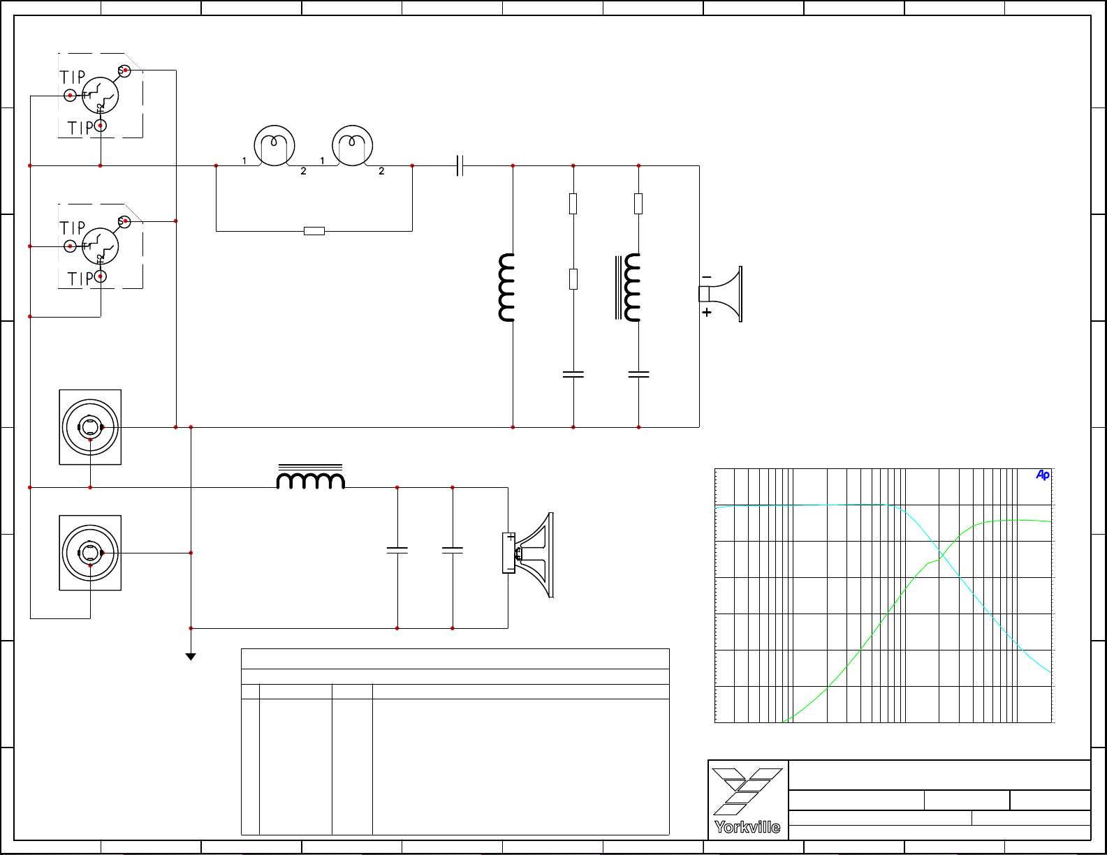
#1141 Bulb
3647
B1
2 2
Function
1/4in JCK
SLEEVE
3 3
J2
3924
LITE1
3641
Bayonet Bulb Socket
#1141 Bulb
3647
B2
LITE2
3641
Bayonet Bulb Socket
R2
15.W
22R
.
C1
4U7 140V
L1
300UH
3784
R4
15.W
.
12R
R3
15.W
.
12R
R1
10.W
.
8R2
L2
2000UH
3716
SP2
YS#7461 8R 40W 1"
HORN
4 4
5 5
6 6
J3:B
FUNCTION
SPEAKON 4C
3628
2+
2_
SPEAKON 4C
FUNCTION
J3:A
J4:B
FUNCTION
SPEAKON 4C
3628
2+
2_
SPEAKON 4C
FUNCTION
J4:A
1_
1+
3628
1_
1+
3628
L3
1500UH
3726
C5
15U
100V
C4
3U3
100V
C2
3U3
100V
SP1
YS#7456 8R 350W 12"
WOOFER
C3
3U3
100V
Yorkville Sound 05/10/05 11:08:33
+20
+10
+0
-10
-20
HORNWOOF
+20
+10
+0
-10
d
B
V
-20
M1280.PCB_DATABASE_HISTORY
MODEL(S):-
DATE DESCRIPTION OF CHANGE
7 7
8 8
A
B
#
31.MAR.2005 1.00
1
2
D
3
D
4
D
5
D
6
D
7
D
8
D
9
D
10
D
11
D
12
D
13
D
C
NX35
VER#
NEW M1280 BOARD
V
N
V
N
V
N
V
N
V
N
V
N
V
N
V
N
V
N
V
N
V
N
V
N
D
E
F
G
-30
-40
-50
20 20k50 100 200 500 1k 2k 5k 10k
Product
Product
Date:
Date:
Filename:
H
Filename:
NX35
NX35
SHEET 1 ofSheet
SHEET 1 ofSheet
Mon Oct 17, 2005
Mon Oct 17, 2005
Hz
HORNWOOF.ATS2
PCB#
M1280
PCB#
M1280
M1280-1V00sch.SCH2002
M1280-1V00sch.SCH2002
I
J
Rev:211V00
Rev:211V00
-30
-40
-50
K
Page 5
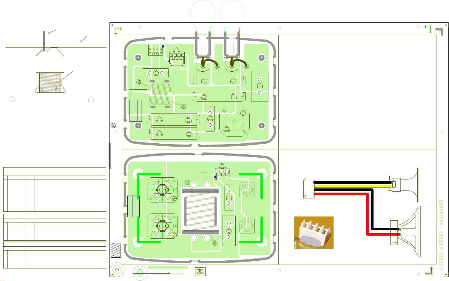
L1, L2 and L3 Leads bending for soldering.
Coil Lead
PCB
#1141 Bulb
3647
B2
#1141 Bulb
3647
B1
Lead thru
Eyelet and Starpad.
Lead bent and leaned
against Teardrop Pad
Place RTV points to fix leads on L1, L2 and L3.
T
R
V
T
R
V
T
R
V
PRODUCTION NOTES:
T
R
V
1. RTV all CAPS, COILS and RESISTORS.
2. NOTE coil inside and outside leads
and install as shown.
3. RTV #3903 molex as shown in picture.
4. Wire length #3641 is 1.5 inches.
5. Use #3743 SNAP ON 0.5 " SPACER.
6. Extra RTV for C1 around the part.
7. X3 is hand inserted.
MODEL(S):-
#
DATE
1
31.MAR.2005
2
D
3
D
4
D
5
D
6
D
7
D
8
D
9
D
10
D
11
D
12
D
13
D
MODEL(S):-
#
DATE
1
D
2
D
3
D
4
D
5
D
6
D
MODEL(S):-
PC#
#
1
PC
2
PC
3
PC
4
PC
5
PC
6
PC
*PLACE IMPLEMENTED CHANGES INTO BOARD HISTORY
M1280.PCB_DATABASE_HISTORY
NX35
VER# DESCRIPTION OF CHANGE
1.00
NEW M1280 BOARD
V
N
V
N
V
N
V
N
V
N
N
V
N
V
V
N
V
N
N
V
V
N
N
V
M1280 DRILLING HISTORY
NX35
VER# DESCRIPTION OF CHANGE
V
N
N
V
N
V
N
VVN
V
N
M1280 PENDING CHANGES
NX35
PENDING CHANGE
X
X
X
X
X
X
CLINCH
ORIGIN
M1280 1/2
VCD
M1280 2/2
NX35
NX35
V1.00
INSERT
ORIGIN
3538
+H +W
-H -W
100V3U3
TVVT
R
R
0R225
{WireGau}
2000UH
V1.00
R
R
NL4MP-1
2+
2+
36283628
FUNCTIONFUNCTION
NL4MP-1
2+
2+
SHORT AXIS
LONG AXIS
T
R
V
3903
PCB CONN 4 CIR BOTTOM .156
W4
1 2 3 4
X3
5942
T
R
V
C3
3716
L2
12R
T
V
15.W
12R
T
V
15.W
1-
SPEAKON 4C
1-
1+
1+
2-
2-
J4
1-
SPEAKON 4C
1-
1+
1+
2-
2-
J3
IRON
W2
Inductor
T
R
V
T
R
V
Bayonet Bulb Socket
3641
LITE1
1
1
T
R
V
T
R
V
R3
R4
100V
3U3
5942
T
R
V
T
R
V
T
R
V
C2
22R
15.W
8R2
10.W
PCB CONN 4 CIR BOTTOM .156
1 2 3 4
Bayonet Bulb Socket
INSIDE WIRE
300UH
T
R
V
T
R
V
3903
T
R
V
T
R
V
T
R
V
3641
LITE2
1
1
T
R
T
R
V
T
R
V
4700
R
3784
22AWG
V
T
R2
R
V
4U7
140V
T
R
V
5950
R1
C1
L1
T
V
OUTSIDE WIRE
W1
SLEEVE
3U3100V
5942
TIP1
39243924
TIP2
J2
C4
3726
L3
3"
IRON
0R207
1500UH
Inductor
T
R
V
T
R
V
T
R
V
C5
M1280Pcb Mech V1.00
M1280
Top Assy V1.00
SLEEVE
FOR PDF
100V 15U
5944
TIP1
TIP2
J1
place RTV molex
pic here
BlankSize - 14000 x 10500
StepAndRepeat - X2@6500,Y1@0
Page 6
Yorkville Sound 05/10/05 11:08:33
+20
+10
+0
-10
d
B
V
HORNWOOF
+20
+10
+0
-10
d
B
V
-20
-30
-40
-50
20 20k50 100 200 500 1k 2k 5k 10k
Hz
HORNWOOF.ATS2
-20
-30
-40
-50
 Loading...