

Page 1
718444-YTG-F-0214
TECHNICAL GUIDE
R-410A
AFFINITY™ SERIES
DNZ/DNQ/DNX/DNY MODELS
2 - 5 TON
60 Hertz
Description
These York® Affinity™ packaged cooling/heating air
conditioners are designed for outdoor installation. Only utility
and duct connections are required at the point of installation.
The single or two stage gas-fired heaters have aluminized steel
tubular heat exchangers and spark to pilot ignition. They are
available in natural gas with field conversion to propane.
Tested in accordance with:
FOR DISTRIBUTION USE ONLY - NOT TO BE USED AT POINT OF RETAIL SALE
Page 2
718444-YTG-F-0214
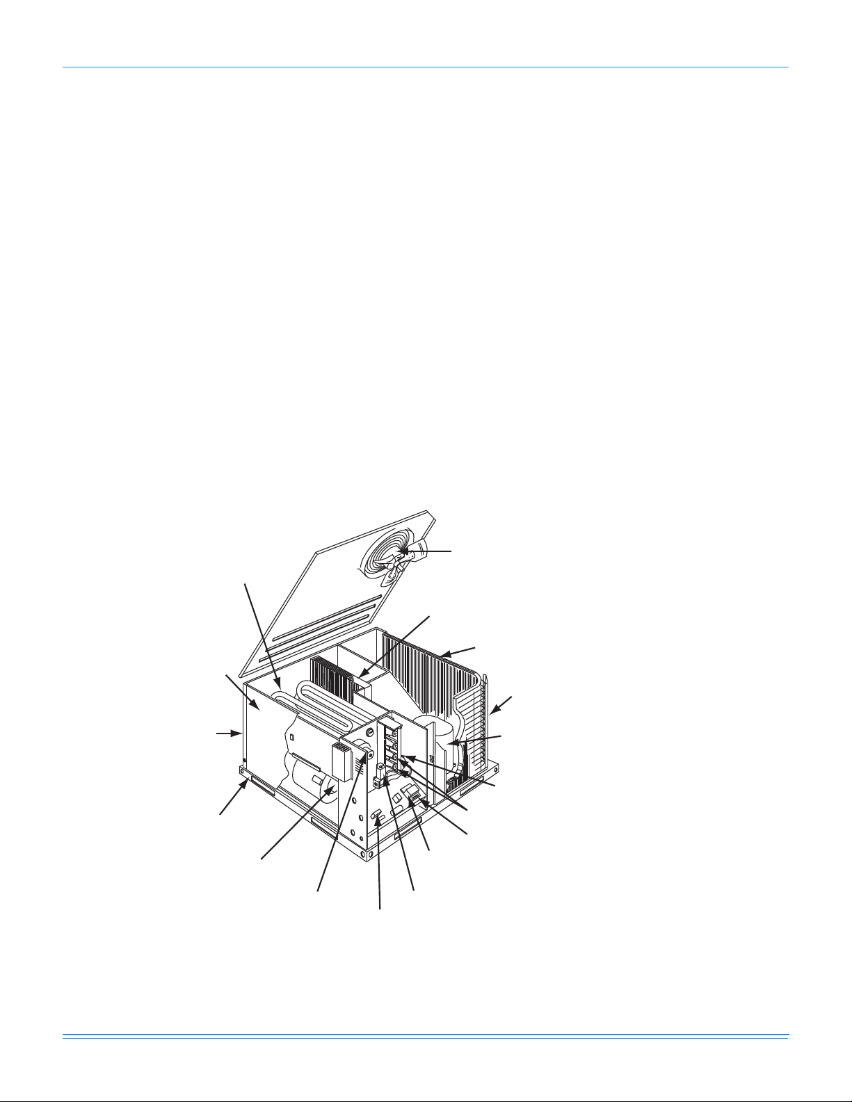
Direct Drive
Condenser Fan Motor
Highly Efficient Enhanced Copper
Tube/Aluminum Fin Evaporator Coil
Highly Efficient Enhanced Copper Tube/Enhanced Aluminum Fin
OR Micro-Channel Aluminum Tube/Aluminum Fin Condenser
Decorative Protective Coil Guard
(See “Features” for Details)
High Efficiency
Compressor Rigidly
Mounted
Pilot Assembly
High Grade Aluminized In-Shot Burners
Low Voltage Terminal Block
Self-Diagnostic Controls
Automatic Gas Valve (1/2" - NPTF)
High Voltage
Terminal Block
Power Draft Motor
Direct Drive Blower Motor With
Slide-Out Blower Assembly
Heavy Gauge
Removable Base Rails
Rear and Bottom Return Air
and Supply Airduct Openings
Long Lasting Powder
Paint Finish
Blow-Through Design With
Reliable Aluminized Steel
Tubular Heat Exchangers
Table of Contents
Description . . . . . . . . . . . . . . . . . . . . . . . . . . . . . . . . . . . . . . . . . . . . . . . . . . . . . . . . . . . . . . . . . . . . . . . . . . . . . . . . . . . . . . . . . . . . 1
Table of Contents . . . . . . . . . . . . . . . . . . . . . . . . . . . . . . . . . . . . . . . . . . . . . . . . . . . . . . . . . . . . . . . . . . . . . . . . . . . . . . . . . . . . . . . 2
Component Location . . . . . . . . . . . . . . . . . . . . . . . . . . . . . . . . . . . . . . . . . . . . . . . . . . . . . . . . . . . . . . . . . . . . . . . . . . . . . . . . . . . . 2
Nomenclature . . . . . . . . . . . . . . . . . . . . . . . . . . . . . . . . . . . . . . . . . . . . . . . . . . . . . . . . . . . . . . . . . . . . . . . . . . . . . . . . . . . . . . . . . . 3
Features and Benefits . . . . . . . . . . . . . . . . . . . . . . . . . . . . . . . . . . . . . . . . . . . . . . . . . . . . . . . . . . . . . . . . . . . . . . . . . . . . . . . . . . . . 3
Guide Specifications . . . . . . . . . . . . . . . . . . . . . . . . . . . . . . . . . . . . . . . . . . . . . . . . . . . . . . . . . . . . . . . . . . . . . . . . . . . . . . . . . . . . . 5
Physical Data . . . . . . . . . . . . . . . . . . . . . . . . . . . . . . . . . . . . . . . . . . . . . . . . . . . . . . . . . . . . . . . . . . . . . . . . . . . . . . . . . . . . . . . . . . . 7
Capacity Performance . . . . . . . . . . . . . . . . . . . . . . . . . . . . . . . . . . . . . . . . . . . . . . . . . . . . . . . . . . . . . . . . . . . . . . . . . . . . . . . . . . 16
Airflow Performance . . . . . . . . . . . . . . . . . . . . . . . . . . . . . . . . . . . . . . . . . . . . . . . . . . . . . . . . . . . . . . . . . . . . . . . . . . . . . . . . . . . . 48
Sound Performance . . . . . . . . . . . . . . . . . . . . . . . . . . . . . . . . . . . . . . . . . . . . . . . . . . . . . . . . . . . . . . . . . . . . . . . . . . . . . . . . . . . . 64
Electrical Data . . . . . . . . . . . . . . . . . . . . . . . . . . . . . . . . . . . . . . . . . . . . . . . . . . . . . . . . . . . . . . . . . . . . . . . . . . . . . . . . . . . . . . . . . 66
Typical Wiring Diagrams . . . . . . . . . . . . . . . . . . . . . . . . . . . . . . . . . . . . . . . . . . . . . . . . . . . . . . . . . . . . . . . . . . . . . . . . . . . . . . . . 68
Weights and Dimensions . . . . . . . . . . . . . . . . . . . . . . . . . . . . . . . . . . . . . . . . . . . . . . . . . . . . . . . . . . . . . . . . . . . . . . . . . . . . . . . . 92
Component Location
Cooling/Gas Unit
2 Johnson Controls Unitary Products
Page 3
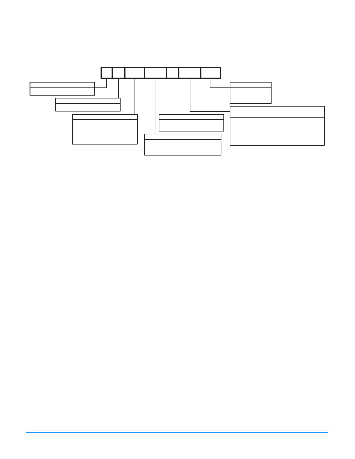
Nomenclature
D 7 036 036 06
N
NZ
Product Category
D = Single Package Air Conditioner
Product Generation
7 = 7th Generation
Factory Installed Gas Heat
N = Single Stage
D = Two Stage (Single Phase Only)
Product Identifier
NZ = R-410A 13 SEER
Gas Heat/Electric
Nominal Gas Heating Output Capacity
(Nominal Low Gas Heat Output Capacity)
036 = 36,000 BTUH
056 = 56,000 BTUH (36,400 BTUH)
065 = 65,000 BTUH
072 = 72,000 BTUH (46,800 BTUH)
090 = 90,000 BTUH (56,160 BTUH)
110 = 110,000 BTUH (70,200 BTUH)
Voltage Code
06 = 208/230-1-60
25 = 208/230-3-60
46 = 460-3-60
024 = 24,000 BTUH
030 = 30,000 BTUH
036 = 36,000 BTUH
042 = 42,000 BTUH
048 = 48,000 BTUH
060 = 60,000 BTUH
Nominal Cooling Capacity (MBH)
NQ = R-410A 14 SEER, 12 EER
NY = R-410A 14 SEER
NX = R-410A 15 SEER
Cooling/Gas Unit
718444-YTG-F-0214
Features and Benefits
Standard Features
• Operating Efficiency - DNZ model gas units provide a
minimum AFUE of 81% and SEERS of 13.0. DNQ Model
gas units provide a minimum AFUE of 81% and 14 SEER
/ 12 EERs. DNY gas units provide a minimum AFUE of
81% and 14 SEER efficiency. DNX model gas units
provide a minimum AFUE of 81% and SEERS of 15.0 to
16.5. All efficiencies exceed legislated minimum levels.
• On Site Flexibility - All model sizes share a common,
compact design cabinet in a single footprint. The installer
has the flexibility of setting one curb and placing the
proper tonnage unit on that curb after the internal load has
been determined. Field convertible duct connections from
side shot to down shot allows the installer to have greater
flexibility with less inventory.
• Lower Installation Cost - Installation time and costs are
reduced by easy power and control wiring connections.
The small base dimension means less space is required
on the ground or roof, plus, the installer can fit this unit
between the wheel wells of full size pick-up truck.
All units are completely wired, charged with R-410A and
tested prior to shipment. Unique test stations using a new
state of the art computerized process system are used to
insure product quality. Refrigerant charge and component
part numbers are verified via computers at assembly. Vital
run test statistics such as system pressure, motor
currents, air velocity and temperature, unit vibration, and
gas system safeties are monitored and recorded by the
system to insure unit performance.
Equal size, side supply and return duct connections
allows easy hook-up of ducts to match low crawl spaces
without transition pieces.
• Utility Connections Made Easy - Gas and electric utility
knockouts are provided through the bottom as well as the
side of the unit. Utility connections can be made quickly and
Johnson Controls Unitary Products 3
with a minimum amount of field labor. A field supplied and
field installed electrical disconnect switch must be installed.
• Convertible Airflow Design - The bottom duct openings
are covered when they leave the factory ready to be used
for a side supply/side return application. If a bottom
supply/bottom return application is desired, you simply
remove the two panels from the bottom of the unit and
place them in the side supply/side return duct openings.
No panel cutting is required and no accessory panel is
necessary. Convertible airflow design allows maximum
field flexibility and minimum inventory.
• Condensate Pan - A non-corrosive, long-lasting, watertight pan is positioned below the evaporator coil to collect
and drain all condensate. Less collection of stagnate
condensate will build-up. The condensate pan conforms
to ASHRAE 62-89 standards (Ventilation for Acceptable
Indoor Air Quality).
• Condensate Drain - The 3/4 inch NPTF connection is
rigidly mounted to assure proper fit and leak tight seal.
• Durable Finish - The cabinet is made of pre-painted
steel. The pre-treated galvanized steel provides a better
paint to steel bond, which resists corrosion and rust creep.
Special primer formulas and matted-textured finish insure
less fading when exposed to sunlight.
• Full Perimeter Base Rails - The easily removable base
rails provide a solid foundation for the entire unit and
protects the unit during shipment. The rails provide fork lift
access from all sides, and rigging holes are also provided
so that an overhead crane can be used to place the units
on a roof. On applications where the unit is placed on a
pad, the base will keep the unit off the pad to deter
corrosion. On applications where height is limited, the inch
high base rails may be removed on location.
• More Attractive Appearance - A single piece Water
Shed top cover containing a top discharge condenser fan
arrangement requires less square footage on installation
and provides a wider variety of installations. The one
piece design adds greater water integrity. Rounded
Page 4

718444-YTG-F-0214
corners with water drip edges add to the attractive
appearance. The cabinet panels have a non-fibrous
insulation that will not release insulation fibers into
conditioned area.
• Top Discharge - The top discharge condenser fan does
not disrupt neighboring areas or dry-out vegetation
surrounding the unit. The warm air from the top mounted fan
is blown up away from the structure and any landscaping.
This allows compact location on multi-unit applications.
• Condenser Coil Grille - All DNZ024 thru 060 and
DNQ060 models utilize a decorative "Wire Form" coil
guard to provide impact protection against large objects.
DNQ024 thru 048, DNY060 and DNX024 thru 048 models
utilize a stamped "Louvered" design which provides
superior impact protection against smaller objects during
transit and after installation.
• Low Operating Sound Level - The upward air flow
carries the normal operating noise up and away from the
living area. The rigid top panel effectively isolates any
motor sound. Isolator mounted compressor and the
rippled fins of the condenser coil muffle the normal fan
motor and compressor operating sounds. The unique
formed base pan also aids in sound alterations with it's
Super-Structure design. This design strategically places
embossments in the pan for optimum strength and rigidity.
• Fan System - All models operate over a wide range of
design conditions with an electrically commutated fan
motor. These units easily match all types of applications
and provide greater on site flexibility to match comfort
requirement. The cooling speed is factory set and can be
field adjusted to a second speed. The heating speed is
factory set to maintain mid point rise at the units heating
input, but can be field adjusted. This allows maximum
comfort conditions.
• Simple Control Circuit - A low voltage printed circuit
board contains a diagnostic indicator light and a low
voltage terminal strip. An additional set of pin connectors
is also provided to simplify the field interface of external
controls. Mate-n-lock plug connectors are used. The
electrical control box is not located in the compressor
compartment. The controls are mounted on a Control-Tilt
control panel to allow the access cover to be removed for
trouble shooting and maintenance without affecting the
normal system operating pressures. All wiring internal to
the unit is color/number coded.
• Protected Compressor - The compressor is internally
protected against high pressure and temperature. This is
accomplished by the simultaneous operation of high
pressure relief valve and a temperature sensor which protect
the compressor if undesirable operating conditions occur.
• Pressure Switches - High pressure and low pressure/
loss of charge switches standard in all units. When
abnormal conditions are sensed through the pressure
switches, the unit will lock out preventing any further
operation until reset or problem is corrected.
• Exclusive Coil Design - Grooved copper tubes and
enhanced aluminum fin construction improves heat
transfer for maximum efficiency and durability or MicroChannel aluminum tube, aluminum fin for long lasting
durability and efficient operation.
• Heat Exchangers - Are corrosion-resistant, aluminizedsteel tubular construction to provide long-life, trouble-free
operation. The unique blow-through design also assures
that condensate does not collect in humid areas when in
the cooling cycle. This adds to longer heat exchanger life
and higher long term efficiencies.
• Post Purge Induced Draft Combustion - Exhausts
combustion products from the heat exchanger upon
completion of the heating cycle to prolong the heat
exchanger life.
• Self Diagnostic Fan Control Module - Due to this self
diagnostic control, less on site time is required to trouble
shoot these units.
• Spark To Pilot Ignition - Provides faster heat delivery.
This ignition is highly reliable, durable and eliminates
nuisance lockouts.
• Multi Port In-shot Burners
required to mix the air and gas. These burners are
constructed of high-grade corrosion-resistant, aluminizedsteel.
• Low Maintenance - Long life, permanently lubricated
condenser and evaporator fan motor bearings need no
annual maintenance adding greater reliability to the unit.
Blower assembly can be easily cleaned by the unique
Slip- Track slide-out blower assembly.
• Secured Service Access Ports - Protected, externally
mounted, re-usable service access ports are provided on
both the high and low lines for ease of evacuating and
charging the system. No final field mounting required.
• Easy Service Access - A large, single panel covers the
electrical and gas controls makes servicing easy. The
blower compartment has an additional large panel with a
built-in handle tab. Removing this panel will allow the
blower assembly to slide-out for easy removal for
maintenance and ease of trouble shooting.
• Replacement Parts - The installer requires no special
training to replace any of the components of these units
and does not need to maintain an inventory of unique parts.
• System Integration - Each unit has the internal ability to
integrate an electronic air cleaner or humidifier to work in
conjunction with the base unit.
- No field adjustment is
Field Installed Accessories
• Low NOx Kit - Kit includes all the necessary hardware
and instructions to field convert units to reduce emissions
to less than 40 nanogram per Joule. California
requirement on single phase models only.
• Propane Conversion Kit - Kit includes burner orifices,
gas valve conversion and installation instructions
necessary to field convert unit from natural gas to propane.
• High Altitude Conversion Kit (Natural Gas/Propane) - Kit
includes all necessary labels and instructions to field alte r
4 Johnson Controls Unitary Products
Page 5

718444-YTG-F-0214
units with natural gas/propane for installations above 2000
feet. Burner orifices must be obtained from Source 1 Parts.
Propane Conversion Kit must be obtained separately.
• Economizer Down Discharge/Supply Kit - Modulating
integrated economizer provides simultaneous operation
between the mechanical cooling and economizer
operation. Independent blade design insures proper
control and less than 1% leak rate. Includes hood and
mesh bird screen filter integrated into the hood, dry bulb
sensor and relief damper. Separate field accessories of
single enthalpy and dual enthalpy are also available. A
built-in barometric relief of 25% is provided.
• Single Enthalpy Sensor - Sensor replaces dry bulb
sensor standard in economizer kit. Provides improved
economizer operation by sensing the dry bulb
temperature from outdoors plus the enthalpy content of
the outdoor air.
• Dual Enthalpy Sensor - Additional sensor to single
enthalpy sensor. Sensor senses both the return air
temperature dry bulb and humidity in conjunction with the
single enthalpy to determine the most economical mix.
Single Enthalpy sensor also required.
• Hail Guard Kit - Kit contains protective grilles made of
expanded aluminum with full perimeter frame. Sloped
hoods are also included to assure maximum protection.
• Anti Short Cycle Timer (DNZ Units Only) - Automaticall y
prevents the compressor from restarting for 5 minutes after
cycled off.Not required if Thermostat 2ET07700224 and
2ET04700224 are used.
• Filter/Frame Kit (Single Phase Only) - Kit contains the
necessary hardware to field install return air filters into the
base unit. Pre-cut filter racks and appropriate cleanable
standard size filters are shipped in one kit. The filter rack
is suitable for either 1" or 2" filters. (1" filter is supplied)
This kit is available for single phase horizontal or vertical
duct application only. Standard in all 3 Phase models.
• Motorized Fresh Air Damper - Designed for duct
mounted side supply/return and unit mounted down
supply/return applications. Damper capable of providing
0% through 50% of outdoor air (field supplied). Closes on
power loss, includes hood and screen assembly.
• Rectangle To Round Adapters - Kit includes one supply
and one return air rectangle to round duct adapter.
Adapters are preformed and designed to fit over current
duct openings on the base unit. Transition is from side
square duct opening to 14" round duct opening.
• Roof Curbs - NRCA approved curbs provide proper fit to
base unit for rooftop installations. Curbs are designed to
be assembled through hinge pins in each corner. Kit also
provides seal strip to assure a water tight seal. 8 and 14
inch high roof curbs are available.
• Manual Outdoor Damper - Provides 0% through 50%
outdoor air capability (field adjustable). Designed for duct
mounted side supply/return applications. Includes hood
and screen assembly.
• Wall Thermostat - The units are designed to operate with
24-volt electronic and electro-mechanical thermostats. All
units can operate with single stage heat/single stage cool
thermostats - with or without the economi z e r.
• Low Ambient Kit - Kit provides necessary hardware to
convert unit to operate in cooling cycle down to 0º F.
Standard unit operation 45º F.
• Transformer Kit - Kit provides necessary hardware to
provide single phase models from factory furnished 40 VA
transformer capability to 75 VA transformer capability.
(Required on installations with economizer or motorized
damper.)
Guide Specifications
General
Units shall be manufactured by Unitary Products in an ISO
9001 certified facility. YORK’s Affinity™ package units give you
the flexibility and choices you need in today’s market. These
packaged cooling/heating air conditioners are designed for
outdoor installation. Only utility and duct connections are
required at the point of installation. The single or two stage gas
fired heaters have aluminized steel tubular heat exchangers
and spark to pilot ignition. They are available in natural gas with
field conversion to propane.
Description
Units shall be factory-assembled, single packaged, Electric
Cooling/Gas Heating units, designed for outdoor mounted
installation. For SEER ratings, refer to technical literature. They
shall have built in, equal size, field convertible duct connections
for down discharge supply/return or horizontal discharge
supply/return. The units shall be factory wired, piped, charged
with R-410A Refrigerant and factory tested prior to shipment. All
unit wiring shall be both numbered and color coded. All units
shall be manufactured in a facility certified to ISO 9001
standards, and the cooling performance shall be rated in
accordance with DOE and AHRI test procedures. The heating
performance shall be rated to DOE and GAMA test procedures.
Units shall be CSA listed and classified to ANSI Z21.47/CAN/
CSA 2.3 standards and UL 1995/CAN/CSA No. 236-M90
conditions.
Unit Cabinet
Unit cabinet shall be constructed of G-90, pre-paint textured
steel, certified at 500 hours salt spray test per ASTM-B117
standards. The unit top shall be a single piece “Water Shed”
design, with drip edges and no-seam corners to provide
optimum water integrity. Unit shall have a rigidly mounted
condenser coil guard to provide protection from objects and
personnel after installation. Indoor blower section shall be
insulated with up to 3/4” thick, aluminum, foil faced insulation,
fastened to prevent insulation from entering the air stream.
Cabinet panels shall be “large” size, easily removable for
servicing and maintenance, with built-in lift handles. Unit shall
be built on a formed, “Super-Structure” design base pan, with
embossments at critical points to add strength, rigidity and aid
in minimizing sound. Full perimeter base rails shall be provided
to assure reliable transit of equipment, overhead rigging, for
Johnson Controls Unitary Products 5
Page 6

718444-YTG-F-0214
truck access and proper sealing on roof curb applications. Base
rails shall be removable, when required, to lower unit height.
Filters shall be furnished and be accessible through a
removable access door, sealed airtight. Units vertical discharge
and return duct configuration shall be designed to fit between
standard 24” O.C. beams without modification to building
structure, duct work and base unit. Condensate pan shall be
internally sloped and conform to ASHRAE 62-89 self-draining
standards, with 3/4” NPTF ridged mount connection.
Indoor (Evaporator) Fan Assembly
Fan shall be direct drive design. Fan wheel shall be double-inlet
type with forward-curved blades, dynamically balanced to
operate smoothly throughout the entire range of opera tion.
Airflow design shall be constant air volume. Bearings shall be
sealed and permanently lubricated for longer life and no
maintenance. Fan assembly shall be “Slip Track” (slide-out)
design for easy removal and cleaning.
Outdoor (Condenser) Fan Assembly
The outdoor fan shall be of the direct-driven propeller type,
discharge air vertically, have aluminum blades riveted to
corrosion resistant steel spider bracket and shall be statically
balanced for smooth operation. The outdoor fan motor shall be
totally enclosed with permanently lubricated bearings and
internally protected against overload conditions.
Refrigerant Components
Compressors:
a. Shall be fully hermetic type, direct drive, internally
protected with internal high-pressure relief and over
temperature protection. The hermetic motor shall be
suction gas cooled and have a voltage range of +/- 10%
of the unit nameplate voltage.
b. Shall have internal isolation and sound muffling to
minimize vibration and noise, and be externally isolated
on a dedicated, independent mounting.
Coils:
a. Evaporator coils shall have aluminum plate fins
mechanically bonded to seamless internally enhanced
copper tubes with all joints brazed.
b. Evaporator coil shall be of the direct expansion, blow
through design.
c. Condenser coils shall have aluminum plate fins
mechanically bonded to seamless internally enhanced
copper tubes with all joints brazed or Mircro-Channel
aluminum tube, aluminum fins.
d. Condenser coil shall be draw through design.
Refrigerant Circuit and Refrigerant Safety Components shall
include:
a. Independent fixed orifice expansion devices.
b. Filter/strainer to eliminate any foreign matter.
Gas Heating Section (If Equipped)
Heat exchanger and exhaust system shall be constructed of
aluminized steel and shall be designed with induced draft
combustion with post purge logic and redundant main gas
valve. The heat exchanger shall be of the tubular type,
constructed of T1-40 aluminized steel for corrosion resistance
and allowing minimum mixed air entering temperature of 40 ºF.
Burners shall be of the in-shot type, constructed of aluminumcoated steel. All gas piping shall enter the unit cabinet at a
single location through either the side or bottom, without any
field modifications. An integrated control board shall provide
timed control of evaporator fan functioning and burner ignition.
Heating section shall be provided with the following minimum
protection:
a. Primary and auxiliary high-temperature limit switches.
b. Induced draft pressure sensor.
c. Flame roll out switch (manual reset).
d. Flame proving controls.
6 Johnson Controls Unitary Products
Page 7
718444-YTG-F-0214
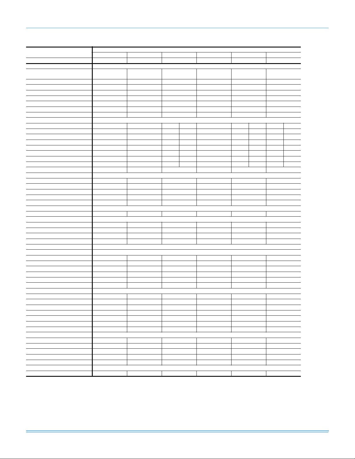
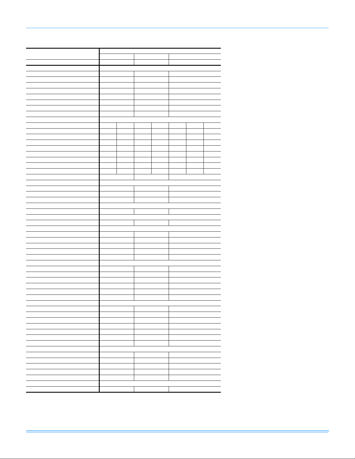
Physical Data
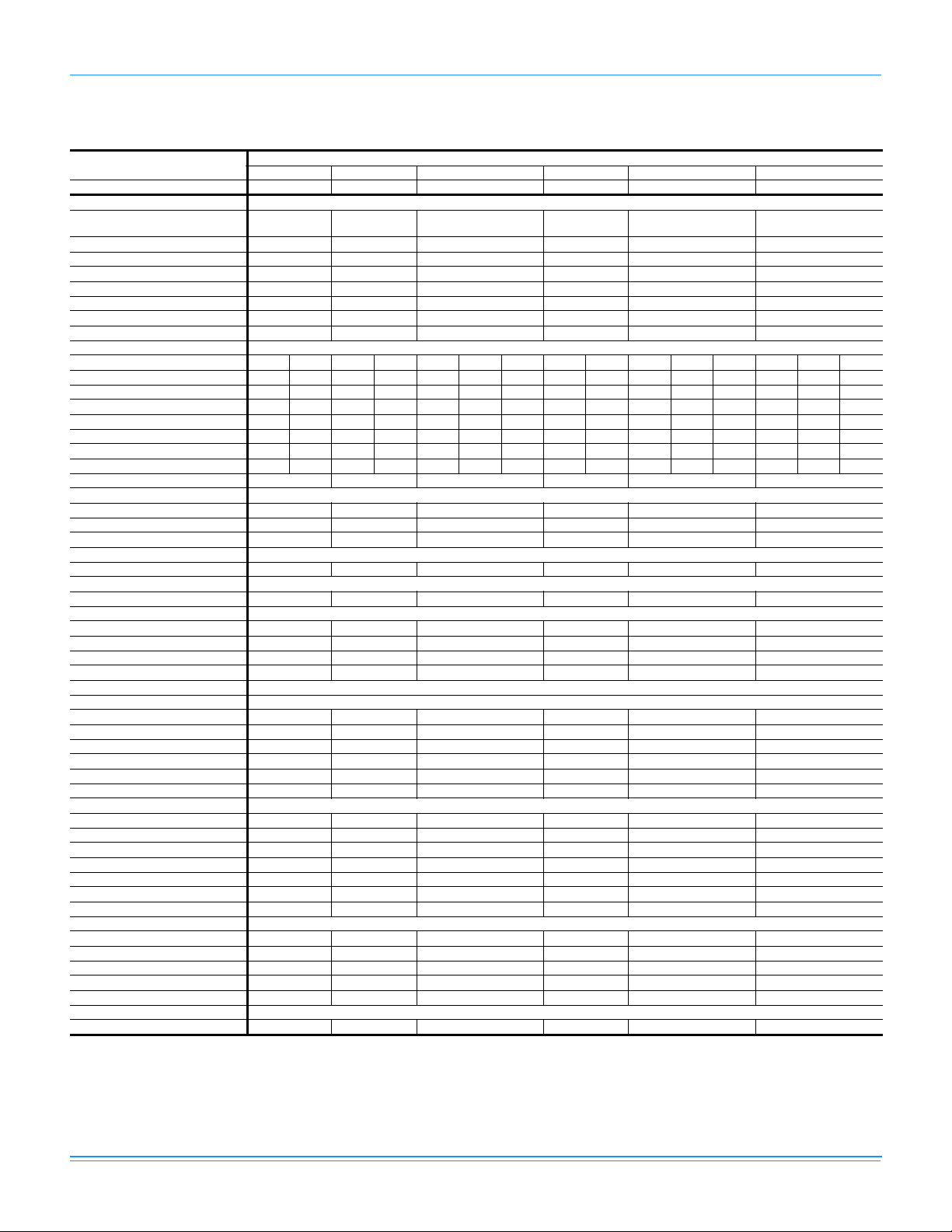
DNZ Single Stage Physical Data
Component
Nominal Tonnage 2.0 2.5 3.0 3.5 4.0 5.0
AHRI COOLING PERFORMANCE
Gross Capacity @ AHRI A point
(MBH)
AHRI net capacity (MBH) 24.0 30.0 34.2 41.5 46.0 56.0
EER 11.6 11.5 11.1 11.6 11.00 11.00
SEER 13.2 13.2 13.2 13.4 13.0 13.0
Nominal CFM 850 940 1200 1300 1550 1600
System power (KW) 2.1 2.7 3.2 3.6 4.2 5.1
Refrigerant type R-410A R-410A R-410A R-410A R410A R410A
Refrigerant charge (lb-oz) 3-10 4-0 4-0 4-14 4-8 5-2
AHRI HEATING PERFORMANCE
Heating model N036 N056 N036 N056 N036 N056 N072 N065 N090 N065 N090 N110 N065 N090 N110
Heat input (K Btu) 45 70 45 70 45 70 90 80 108 80 108 135 80 108 135
Heat output (K Btu) 36 56 36 56 36 56 72 64 87 64 87 108 64 87 108
AFUE % 81.0 81.0 81.0 81.0 81.0 81.0 81.0 81.0 81.0 81.0 81.0 81.0 81.0 81.0 81.0
No. burners 232323434345345
No. stages 111111111111111
Temperature Rise Range (ºF) 25-55 30-60 25-5 5 30-60 25-55 25-55 30-60 25-55 45-75 25-55 35-65 45-75 25-55 35-65 45-75
Gas Limit Setting (ºF) 140 160 140 160 140 160 160 150 175 150 175 160 150 175 160
Gas piping connection (in.) 1/2 1/2 1/2 1/2 1/2 1/2
DIMENSIONS (inches)
Length 49 1/8 49 1/8 49 1/8 49 1/8 49 1/8 49 1/8
Width 47 1/4 47 1/4 47 1/4 47 1/4 47 1/4 47 1/4
Height 33 1/2 33 1/2 33 1/2 41 1/2 41 1/2 41 1/2
OPERATING WT. (lbs.)
Unit Weight (lbs.) 378 398 402 460 465 480
Type Recip 1-spd Recip 1-spd Recip 1-spd Recip 1-spd Scroll 1-spd Scroll 1-spd
Face area (Sq. Ft.) 11.9 11.9 11.9 15 15 15
Rows 11111 1
Fins per inch 23 23 23 23 23 23
Tube diameter (in.) 0.7 1 / 18 0.71 / 18 0.71 / 18 0.71 / 18 0.71 / 18 0.71 / 18
Circuitry Type 2-pass Micro-Channel
Face area (Sq. Ft.) 3.4 3.4 3.4 4.4 4.4 4.4
Rows 23333 4
Fins per inch 15 13 13 16 16 13
Tube diameter 3/8 3/8 3/8 3/8 3/8 3/8
Circuitry Type Interlaced Interlaced Interlaced Interlaced Interlaced Interlaced
Refrigerant control Orifice Orifice Orifice Orifice TXV TXV
Fan diameter (Inch) 22 22 22 22 22 22
Type Prop Prop Prop Prop Prop Prop
Drive type Direct Direct Direct Direct Direct Direct
No. speeds 1 1 1 1 1 1
Motor HP 1/4 1/4 1/4 1/3 1/3 1/2
RPM 1100 1100 1100 1120 1120 1090
Nominal total CFM 2400 2400 2400 3200 3200 3200
Fan Size (Inch) 10 x 8 10 x 8 11 x 10 11 x 10 11 x 10 11 x 10
Type Centrifugal Centrifugal Centrifugal Centrifugal Centrifugal Centrifugal
Motor HP 1/2 3/4 3/4 3/4 1 1
RPM Variable Variable Variable Variable Variable Variable
Frame size 48 48 48 48 48 48
Quantity - Size 1 - 20 x 20 x 1 1 - 20 x 20 x 1 1 - 20 x 20 x 1 2 - 20 x 12 x 1 2 - 20 x 12 x 1 2 - 20 x 12 x 1
COMPRESSOR
CONDENSER COIL DATA
EVAPORATOR COIL DATA
CONDENSER FAN DATA
DIRECT DRIVE EVAP FAN DATA
FILTERS
DNZ024 DNZ030 DNZ036 DNZ042 DNZ048 DNZ060
24.7 30.8 35.6 43.0 48.8 59.5
Models
Johnson Controls Unitary Products 7
Page 8
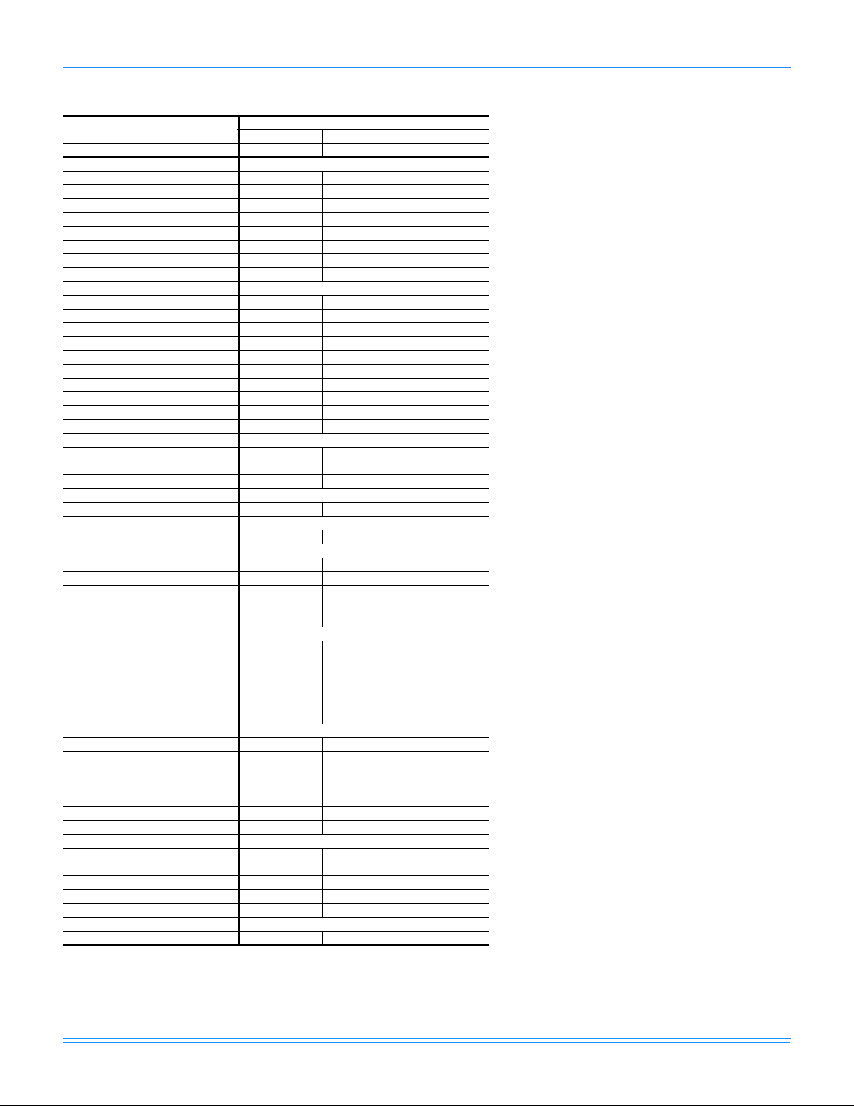
718444-YTG-F-0214
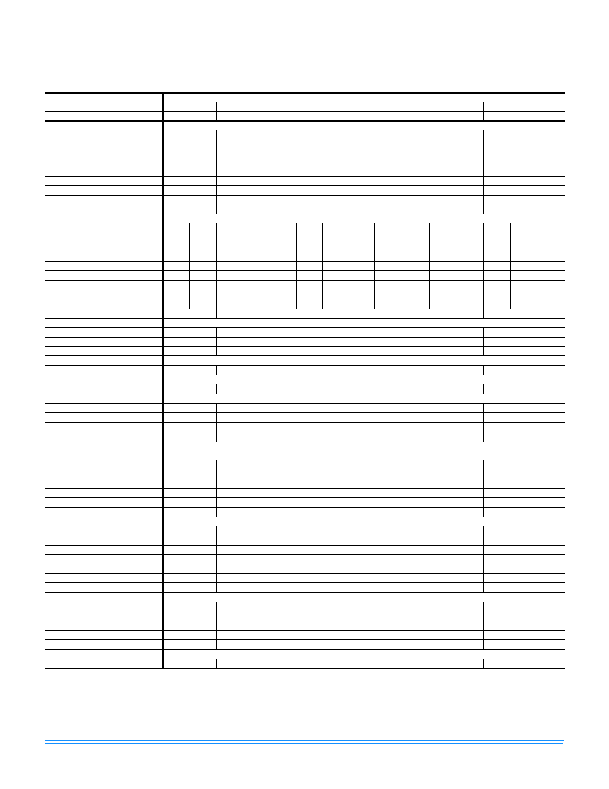
DNZ Two Stage Physical Data
Component
Nominal Tonnage 2.0 2.5 3.0 3.5 4.0 5.0
AHRI COOLING PERFORMANCE
Gross Capacity @ AHRI A point
(MBH)
AHRI net capacity (MBH) 24.0 30.0 34.2 41.5 46.0 56.0
EER 11.6 11.5 11.1 11.6 11.00 11.00
SEER 13.2 13.2 13.2 13.4 13.0 13.0
Nominal CFM 850 940 1200 1300 1550 1600
System power (KW) 2.1 2.7 3.2 3.6 4.2 5.1
Refrigerant type R-410A R-410A R-410A R-410A R410A R410A
Refrigerant charge (lb-oz) 3-10 4-0 4-0 4-14 4-8 5-2
AHRI HEATING PERFORMANCE
Heating model D056 D056 D056 D072 D090 D090 D110 D090 D110
Heat input (K Btu) 70/45.5 70/45.5 70/45.5 90/58.5 108/70.2 108/70.2 135/87.8 108/70.2 135/87.8
Heat output (K Btu) 56/36.4 56/36.4 56/36. 4 72/46. 8 87/56.2 87/56.2 108/70.2 87/56.2 108/70.2
AFUE % 81.0 81.0 81.0 81.0 81.0 81.0 81.0 81.0 81.0
No. burners 3 3 34 4 4545
No. stages 2 2 22 2 2222
Temperature Rise Range (ºF) 30-60 30-60 25-55 30-60 45-75 35-65 45-75 35-65 45-75
Gas Limit Setting (ºF) 160 160 160 160 175 175 170 175 170
Gas piping connection (in.) 1/2 1/2 1/2 1/2 1/2 1/2
DIMENSIONS (inches)
Length 49 1/8 49 1/8 49 1/8 49 1/8 49 1/8 49 1/8
Width 47 1/4 47 1/4 47 1/4 47 1/4 47 1/4 47 1/4
Height 33 1/2 33 1/2 33 1/2 41 1/2 41 1/2 41 1/2
OPERATING WT. (lbs.)
Unit Weight (lbs.) 378 398 402 460 465 480
COMPRESSOR
Type Recip 1-spd Recip 1-spd Recip 1-spd Recip 1-spd Scroll 1-spd Scroll 1-spd
CONDENSER COIL DATA
Face area (Sq. Ft.) 11.9 11.9 11.9 15 15 15
Rows 111111
Fins per inch 23 23 23 23 23 23
Tube diameter (in.) 0.71 / 18 0.71 / 18 0.71 / 18 0.71 / 18 0.71 / 18 0.71 / 18
Circuitry Type 2-pass Micro-Channel
EVAPORATOR COIL DATA
Face area (Sq. Ft.) 3.4 3.4 3.4 4.4 4.4 4.4
Rows 233334
Fins per inch 15 13 13 16 16 13
Tube diameter 3/8 3/8 3/8 3/8 3/8 3/8
Circuitry Type Interlaced Interlaced Interlaced Interlaced Interlaced Interlaced
Refrigerant control Orifice Orifice Orifice Orifice TXV TXV
CONDENSER FAN DATA
Fan diameter (Inch) 22 22 22 22 22 22
Type Prop Prop Prop Prop Prop Prop
Drive type Direct Direct Direct Direct Direct Direct
No. speeds 111111
Motor HP 1/4 1/4 1/4 1/3 1/3 1/2
RPM 1100 1100 1100 1100 1100 1090
Nominal total CFM 2400 2400 2400 3200 3200 3200
DIRECT DRIVE EVAP FAN DATA
Fan Size (Inch) 10 x 8 10 x 8 11 x 10 11 x 10 11 x 10 11 x 10
Type Centrifugal Centrifugal Centrifugal Centrifugal Centrifugal Centrifugal
Motor HP 1/2 3/4 3/4 3/4 1 1
RPM Variable Variable Variable Variable Variable Variable
Frame size 48 48 48 48 48 48
FILTERS
Quantity - Size 1 - 20 x 20 x 1 1 - 20 x 20 x 1 1 - 20 x 20 x 1 2 - 20 x 12 x 1 2 - 20 x 12 x 1 2 - 20 x 12 x 1
DNZ024 DNZ030 DNZ036 DNZ042 DNZ048 DNZ060
24.7 30.8 35.6 43.0 48.8 59.5
Models
8 Johnson Controls Unitary Products
Page 9
718444-YTG-F-0214
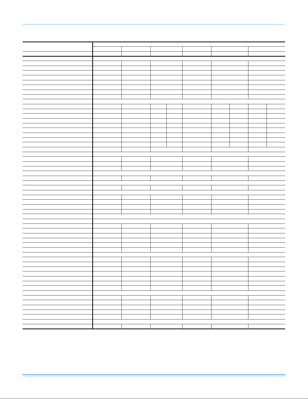
DNQ Single Stage Physical Data
Component
Nominal Tonnage 2.0 2.5 3.0 3.5 4.0 5.0
AHRI COOLING PERFORMANCE
Gross Capacity @ AHRI A point
(MBH)
AHRI net capacity (MBH) 23.6 29.0 34.4 40.0 48.0 55.0*
EER 12.0 12.0 12.0 12.0 12.0 12.0*
SEER 14.0 14.0 14.0 14.0 14.0 14.0*
Nominal CFM 800 900 1100 1400 1500 1550
System power (KW) 2.0 2.4 2.9 3.3 4.0 4.6
Refrigerant type R-410A R-410A R-410A R410A R-410A R-410A
Refrigerant charge (lb-oz) 3-8 3-2 3-10 4-9 4-6 5-15
AHRI HEATING PERFORMANCE
Heating model N036 N056 N036 N056 N036 N056 N072 N065 N090 N065 N090 N110 N065 N090 N110
Heat input (K Btu) 45 70 45 70 45 70 90 80 108 80 108 135 80 108 135
Heat output (K Btu) 36 56 36 56 36 56 72 64 87 64 87 108 64 87 108
AFUE % 81.0 81.0 81.0 81.0 81.0 81.0 81.0 81.0 81.0 81.0 81.0 81.0 81.0 81.0 81.0
No. burners 232323434345345
No. stages 111111111111111
Temperature Rise Range (ºF) 25-55 30-60 25-55 30-60 25-55 25-55 30-60 25-55 45-75 25-55 35-65 45-75 25-55 35-65 45-75
Max. Outlet Air Temp. (ºF) 165 175 165 175 165 175 175 175 175 175 175 175 175 175 175
Gas Limit Setting (ºF) 140 160 140 160 140 160 160 140 160 150 175 160 150 175 160
Gas piping connection (in.) 1/2 1/2 1/2 1/2 1/2 1/2
DIMENSIONS (inches)
Length 49 1/8 49 1/8 49 1/8 49 1/8 49 1/8 49 1/8
Width 47 1/4 47 1/4 47 1/4 47 1/4 47 1/4 47 1/4
Height 33 1/2 33 1/2 33 1/2 41 1/2 41 1/2 41 1/2
OPERATING WT. (lbs.)
Unit Weight (lbs.) 390 425 430 485 490 530
COMPRESSOR
Type Recip 1-spd Scroll 1-spd Scroll 1-spd Scroll 1-spd Scroll 1-spd Scroll 1-spd
CONDENSER COIL DATA
Face area (Sq. Ft.) 7.9 11.9 11.9 15 15 15
Rows 1111 1 1
Fins per inch 23 23 23 23 23 23
Tube diameter (in.) 0.71 / 18 0.71 / 18 0.71 / 18 0.71 / 18 0.71 / 18 0.98 / 25
Circuitry Type 2-pass Micro-Channel
EVAPORATOR COIL DATA
Face area (Sq. Ft.) 3.4 3.4 3.4 4.4 4.4 4.4
Rows 2333 3 4
Fins per inch 15 13 13 16 16 13
Tube diameter 3/8 3/8 3/8 3/8 3/8 3/8
Circuitry Type Int e rla ce d Interlaced Interlac ed Interlaced Interlaced Interlaced
Refrigerant control TXV TXV TXV TXV TXV TXV
CONDENSER FAN DATA
Fan diameter (Inch) 22 22 22 22 22 22
Type Prop Prop Prop Prop Prop Prop
Drive type Direct Direct Direct Direct Direct Direct
No. speeds 1 1 1 1 1 1
Motor HP 1/4 1/4 1/4 1/3 1/3 1/3
RPM 1100 1100 1100 1100 1100 1100
Nominal total CFM 2400 2400 2400 3200 3200 3200
DIRECT DRIVE EVAP FAN DATA
Fan Size (Inch) 10 x 8 10 x 8 11 x 10 12 x 11 12 x 11 12 x 11
Type Centrifugal Centrifugal Centrifugal Centrifugal Centrifugal Centrifugal
Motor HP 1/2 3/4 3/4 3/4 1 1
RPM Variable Variable Variable Variable Variable Variable
Frame size 48 48 48 48 48 48
FILTERS
Quantity - Size 1 - 20 x 20 x 1 1 - 20 x 20 x 1 1 - 20 x 20 x 1 2 - 20 x 12 x 1 2 - 20 x 12 x 1 2 - 20 x 12 x 1
DNQ024 DNQ030 DNQ036 DNQ042 DNQ048 DNQ060
24.0 29.8 35.7 41.5 49.6 56.8*
Models
Johnson Controls Unitary Products 9
Page 10
718444-YTG-F-0214
DNQ Two Stage Physical Data
Component
Nominal Tonnage 2.0 2.5 3.0 3.5 4.0 5.0
AHRI COOLING PERFORMANCE
Gross Capacity @ AHRI A point (MBH) 24.0 29.8 35.7 41.5 49.6 56.8*
AHRI net capacity (MBH) 23.6 29.0 34.4 40.0 48.0 55.0*
EER 12.0 12.0 12.0 12.0 12.0 12.0*
SEER 14.0 14.0 14.0 14.0 14.0 14.0*
Nominal CFM 800 900 1100 1400 1500 1550
System power (KW) 2.0 2.4 2.9 3.3 4.0 4.6
Refrigerant type R-410A R-410A R-410A R410A R-410A R-410A
Refrigerant charge (lb-oz) 3-8 3-2 3-10 4-9 4-6 5-15
AHRI HEATING PERFORMANCE
Heating model D056 D056 D056 D072 D090 D090 D110 D090 D110
Heat input (K Btu) 70/45.5 70/45.5 70/45.5 90/58.5 108/70.2 108/70.2 135/87.8 108/70.2 135/87.8
Heat output (K Btu) 56/36.4 56/36.4 56/36.4 72/46.8 87/56.2 87/56.2 108/70.2 87/56.2 108/70.2
AFUE % 81.0 81.0 81.0 81.0 81.0 81.0 81.0 81.0 81.0
No. burners 3 3 3 4 4 4 5 4 5
No. stages 2 2 2 2 2 2 2 2 2
Temperature Rise Range (ºF) 30-60 30-60 25-55 30-60 45-75 35-65 45-75 35-65 45-75
Max. Outlet Air Temp. (ºF) 175 175 175 175 175 175 175 175 175
Gas Limit Setting (ºF) 160 160 160 160 175 175 170 175 170
Gas piping connection (in.) 1/2 1/2 1/2 1/2 1/2 1/2
DIMENSIONS (inches)
Length 49 1/8 49 1/8 49 1/8 49 1/8 49 1/8 49 1/8
Width 47 1/4 47 1/4 47 1/4 47 1/4 47 1/4 47 1/4
Height 33 1/2 33 1/2 33 1/2 41 1/2 41 1/2 41 1/2
OPERATING WT. (lbs.)
Unit Weight (lbs.) 390 425 430 485 490 530
COMPRESSOR
Type Recip 1-spd Scroll 1-spd Scroll 1-spd Scroll 1-spd Scroll 1-spd Scroll 1-spd
CONDENSER COIL DATA
Face area (Sq. Ft.) 7.9 11.9 11.9 15 15 15
Rows 1 1 1 1 1 1
Fins per inch 23 23 23 23 23 23
Tube diameter (in.) 0.71 / 18 0.71 / 18 0.71 / 18 0.71 / 18 0.71 / 18 0.98 / 25
Circuitry Type 2-pass Micro-Channel
EVAPORATOR COIL DATA
Face area (Sq. Ft.) 3.4 3.4 3.4 4.4 4.4 4.4
Rows 2 3 3 3 3 4
Fins per inch 15 13 13 16 16 13
Tube diameter 3/8 3/8 3/8 3/8 3/8 3/8
Circuitry Type Interlaced Interlaced Interlaced Interlaced Interlaced Interlaced
Refrigerant control TXV TXV TXV TXV TXV TXV
CONDENSER FAN DATA
Fan diameter (Inch) 22 22 22 22 22 22
Type Prop Prop Prop Prop Prop Prop
Drive type Direct Direct Direct Direct Direct Direct
No. speeds 1 1 1 1 1 1
Motor HP 1/4 1/4 1/4 1/3 1/3 1/3
RPM 1100 1100 1100 1100 1100 1100
Nominal total CFM 2400 2400 2400 3200 3200 3200
DIRECT DRIVE EVAP FAN DATA
Fan Size (Inch) 10 x 8 10 x 8 11 x 10 12 x 11 12 x 11 12 x 11
Type Centrifugal Centrifugal Centrifugal Centrifugal Centrifugal Centrifugal
Motor HP 1/2 3/4 3/4 3/4 1 1
RPM Variable Variable Variable Variable Variable Variable
Frame size 48 48 48 48 48 48
FILTERS
Quantity - Size 1 - 20 x 20 x 1 1 - 20 x 20 x 1 1 - 20 x 20 x 1 2 - 20 x 12 x 1 2 - 20 x 12 x 1 2 - 20 x 12 x 1
DNQ024 DNQ030 DNQ036 DNQ042 DNQ048 DNQ060
Models
10 Johnson Controls Unitary Products
Page 11
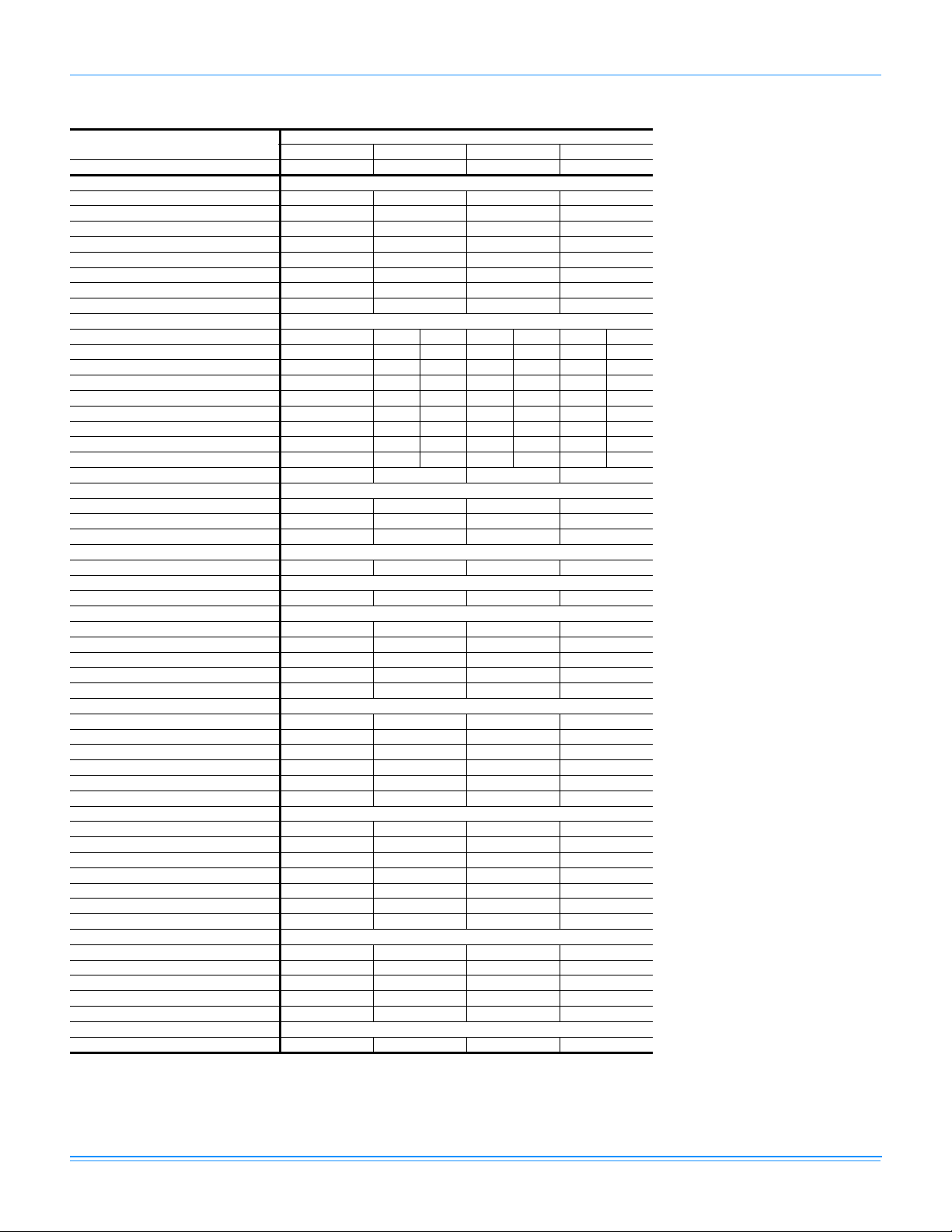
DNY Two Stage Physical Data
Component
Nominal Tonnage 2.0 3.0 4.0 5.0
AHRI COOLING PERFORMANCE
Gross Capacity @ AHRI A point (MBH) 24.3 35.6 50.0 59.6
AHRI net capacity (MBH) 23.8 34.6 48.0 56.5
EER 11.1 11.0 11.0 10.6
SEER 14.0 14.0 14.0 13.7
Nominal CFM 800 1200 1550 1650
System power (KW) 2.1 3.1 4.4 5.4
Refrigerant type R-410A R-410A R-410A R-410A
Refrigerant charge (lb-oz) 5-0 7-8 9-8 10-0
AHRI HEATING PERFORMANCE
Heating model D056 D056 D072 D090 D110 D090 D110
Heat input (K Btu) 70/45.5 70/45.5 90/58.5 108/70.2 135/87.8 108/70.2 135/87.8
Heat output (K Btu) 56/36.4 56/36.4 72/46.8 87/56.2 108/70.2 87/56.2 108/70.2
AFUE % 81.0 81.0 81.0 81.0 81.0 81.0 81.0
No. burners 3 344545
No. stages 2 222222
Temperature Rise Range (ºF) 30-60 25-55 30-60 35-65 45-75 35-65 45-75
Max. Outlet Air Temp. (ºF) 175 175 175 175 175 175 175
Gas Limit Setting (ºF) 160 160 150 170 160 170 160
Gas piping connection (in.) 1/2 1/2 1/2 1/2
DIMENSIONS (inches)
Length 49 1/8 49 1/8 49 1/8 49 1/8
Width 47 1/4 47 1/4 47 1/4 47 1/4
Height 33 1/2 33 1/2 41 1/2 41 1/2
OPERATING WT. (lbs.)
Unit Weight (lbs.) 400 440 500 540
COMPRESSOR
Type Scroll 2-spd Scroll 2-spd Scroll 2-spd Scroll 2-spd
CONDENSER COIL DATA
Face area (Sq. Ft.) 11.7 11.7 14.7 14.7
Rows 1222
Fins per inch 20 16 20 20
Tube diameter (in.) 3/8 3/8 3/8 3/8
Circuitry Type Interlaced Interlaced Interlaced Interlaced
EVAPORATOR COIL DATA
Face area (Sq. Ft.) 3.4 3.4 4.4 4.4
Rows 2333
Fins per inch 15 13 16 16
Tube diameter 3/8 3/8 3/8 3/8
Circuitry Type Interlaced Interlaced Interlaced Interlaced
Refrigerant control TXV TXV TXV TXV
CONDENSER FAN DATA
Fan diameter (Inch) 22 22 22 22
Type Prop Prop Prop Prop
Drive type Direct Direct Direct Direct
No. speeds 1112
Motor HP 1/4 1/4 1/3 1/3
RPM 1100 1100 1100 850/1100
Nominal total CFM 2400 2400 3000 3000
DIRECT DRIVE EVAP FAN DATA
Fan Size (Inch) 10 x 8 11 x 10 11 x 10 11 x 10
Type Centrifugal Centrifugal Centrifugal Centrifugal
Motor HP 1/2 3/4 1 1
RPM Variable Variable Variable Variable
Frame size 48 48 48 48
FILTERS
Quantity - Size 1 - 20 x 20 x 1 1 - 20 x 20 x 1 2 - 20 x 12 x 1 2 - 20 x 12 x 1
DNY024 DNY036 DNY048 DNY060
Models
718444-YTG-F-0214
Johnson Controls Unitary Products 11
Page 12
718444-YTG-F-0214
DNX Single Stage Gas Heat
Component
Nominal Tonnage 2.0 3.0 4.0
AHRI COOLING PERFORMANCE
Gross Capacity @ AHRI A point (MBH) 24.6 38.4 50.0
AHRI net capacity (MBH) 24.0 37.0 48.0
EER 11.5 12.3 11.2
SEER 15.0 16.5 15.0
Nominal CFM 800 1275 1550
System power (KW) 2.1 3.0 4.3
Refrigerant type R-410A R-410A R-410A
Refrigerant charge (lb-oz) 7-8 9-12 9-8
AHRI HEATING PERFORMANCE
Heating model N036 N056 N065 N090 N065 N090 N110
Heat input (K Btu) 45 70 80 108 80 108 135
Heat output (K Btu) 36 56 64 87 64 87 108
AFUE % 81.0 81.0 81.0 81.0 81.0 81.0 81.0
No. burners 2334345
No. stages 1111111
Temperature Rise Range (ºF) 25-55 30-60 25-55 45-75 25-55 35-65 45-75
Max. Outlet Air Temp. (ºF) 165 175 165 175 165 175 175
Gas Limit Setting (ºF) 140 160 140 160 150 170 160
Gas piping connection (in.) 1/2 1/2 1/2
DIMENSIONS (inches)
Length 49 1/8 49 1/8 49 1/8
Width 47 1/4 47 1/4 47 1/4
Height 33 1/2 41 1/2 41 1/2
OPERATING WT. (lbs.)
Unit Weight (lbs.) 440 480 500
COMPRESSOR
Type Scroll 2-spd Scroll 2-spd Scroll 2-spd
CONDENSER COIL DATA
Face area (Sq. Ft.) 11.7 14.7 14.7
Rows 2 2 2
Fins per inch 20 20 20
Tube diameter (in.) 3/8 3/8 3/8
Circuitry Type Interlaced Interlaced Interlaced
EVAPORATOR COIL DATA
Face area (Sq. Ft.) 3.4 4.4 4.4
Rows 2 3 3
Fins per inch 15 16 16
Tube diameter 3/8 3/8 3/8
Circuitry Type Interlaced Interlaced Interlaced
Refrigerant control TXV TXV TXV
CONDENSER FAN DATA
Fan diameter (Inch) 22 22 22
Type Prop Prop Prop
Drive type Direct Direct Direct
No. speeds 1 2 2
Motor HP 1/4 1/3 1/3
RPM 1100 900/1100 900/1100
Nominal total CFM 2400 2400 3000
DIRECT DRIVE EVAP FAN DATA
Fan Size (Inch) 10 x 8 11 x 10 11 x 10
Type Centrifugal Centrifugal Centrifugal
Motor HP 1/2 1 1
RPM Variable Variable Variable
Frame size 48 48 48
FILTERS
Quantity - Size 1 - 20 x 20 x 1 2 - 20 x 12 x 1 2 - 20 x 12 x 1
DNX024 DNX036 DNX048
Models
12 Johnson Controls Unitary Products
Page 13
DNX Two Stage Gas Heat
Component
Nominal Tonnage 2.0 3.0 4.0
AHRI COOLING PERFORMANCE
Gross Capacity @ AHRI A point (MBH) 24.6 38.4 50.0
AHRI net capacity (MBH) 24.0 37.0 48.0
EER 11.5 12.3 11.2
SEER 15.0 16.5 15.0
Nominal CFM 800 1275 1550
System power (KW) 2.1 3.0 4.3
Refrigerant type R-410A R-410A R-410A
Refrigerant charge (lb-oz) 7-8 9-12 9-8
AHRI HEATING PERFORMANCE
Heating model D056 D090 D090 D110
Heat input (K Btu) 70/45.5 108/70.2 108/70.2 135/87.8
Heat output (K Btu) 56/36.4 87/56.2 87/56.2 108/70.2
AFUE % 81.0 81.0 81.0 81.0
No. burners 3 4 4 5
No. stages 2 2 2 2
Temperature Rise Range (ºF) 30-60 45-75 35-65 45-75
Max. Outlet Air Temp (ºF) 175 175 175 175
Gas Limit Setting (ºF) 160 175 170 160
Gas piping connection (in.) 1/2 1/2 1/2
DIMENSIONS (inches)
Length 49 1/8 49 1/8 49 1/8
Width 47 1/4 47 1/4 47 1/4
Height 33 1/2 41 1/2 41 1/2
OPERATING WT. (lbs.)
Unit Weight (lbs.) 440 480 500
COMPRESSOR
Type Scroll 2-spd Scroll 2-spd Scroll 2-spd
CONDENSER COIL DATA
Face area (Sq. Ft.) 11.7 14.7 14.7
Rows 222
Fins per inch 20 20 20
Tube diameter (in.) 3/8 3/8 3/8
Circuitry Type Interlaced Interlaced Interlaced
EVAPORATOR COIL DATA
Face area (Sq. Ft.) 3.4 4.4 4.4
Rows 233
Fins per inch 15 16 16
Tube diameter 3/8 3/8 3/8
Circuitry Type Interlaced Interlaced Interlaced
Refrigerant control TXV TXV TXV
CONDENSER FAN DATA
Fan diameter (Inch) 22 22 22
Type Prop Prop Prop
Drive type Direct Direct Direct
No. speeds 1 2 1
Motor HP 1/4 1/3 1/3
RPM 1100 900/1100 900/1100
Nominal total CFM 2400 2400 3000
DIRECT DRIVE EVAP FAN DATA
Fan Size (Inch) 10 x 8 11 x 10 11 x 10
Type Centrifugal Centrifugal Centrifugal
Motor HP 1/2 1 1
RPM Variable Variable Variable
Frame size 48 48 48
FILTERS
Quantity - Size 1 - 20 x 20 x 1 2 - 20 x 12 x 1 2 - 20 x 12 x 1
DNX024 DNX036 DNX048
Models
718444-YTG-F-0214
Johnson Controls Unitary Products 13
Page 14
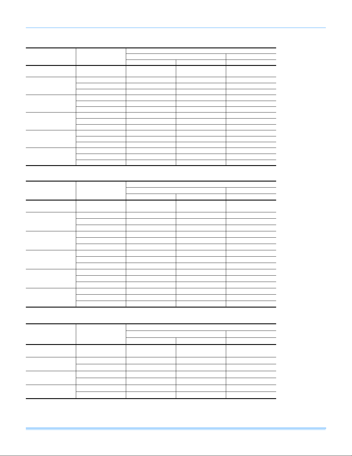
718444-YTG-F-0214
DNZ Unit Limitations
Model
(Tons)
DNZ024
(2.0)
DNZ030
(2.5)
DNZ036
(3.0)
DNZ042
(3.5)
DNZ048
(4.0)
DNZ060
(5.0)
DNQ Unit Limitations
Model
(Tons)
DNQ024
(2.0)
DNQ030
(2.5)
DNQ036
(3.0)
DNQ042
(3.5)
DNQ048
(4.0)
DNQ060
(5.0)
Unit Limitations
Unit Voltage
208/230-1-60 187 252 125
208/230-1-60 187 252 125
208/230-3-60 187 252 125
460-3-60 432 504 125
208/230-1-60 187 252 125
208/230-3-60 187 252 125
460-3-60 432 504 125
208/230-1-60 187 252 125
208/230-3-60 187 252 125
460-3-60 432 504 125
208/230-1-60 187 252 115
208/230-3-60 187 252 115
460-3-60 432 504 115
208/230-1-60 187 252 115
208/230-3-60 187 252 115
460-3-60 432 504 115
Unit Voltage
208/230-1-60 187 252 125
208/230-1-60 187 252 115
208/230-3-60 187 252 115
460-3-60 432 504 115
208/230-1-60 187 252 115
208/230-3-60 187 252 115
460-3-60 432 504 115
208/230-1-60 187 252 125
208/230-3-60 187 252 125
460-3-60 432 504 125
208/230-1-60 187 252 115
208/230-3-60 187 252 115
460-3-60 432 504 115
208/230-1-60 187 252 125
208/230-3-60 187 252 125
460-3-60 432 504 125
Applied Voltage Outdoor DB Temp
Min Max Max (°F)
Unit Limitations
Applied Voltage Outdoor DB Temp
Min Max Max (°F)
DNY Unit Limitations
Model
(Tons)
DNY024
(2.0)
DNY036
(3.0)
DNY048
(4.0)
DNY060
(5.0)
Unit Voltage
208/230-1-60 187 252 115
208/230-1-60 187 252 115
208/230-3-60 187 252 115
208/230-1-60 187 252 115
208/230-3-60 187 252 115
208/230-1-60 187 252 115
208/230-3-60 187 252 115
Applied Voltage Outdoor DB Temp
Min Max Max (°F)
Unit Limitations
14 Johnson Controls Unitary Products
Page 15
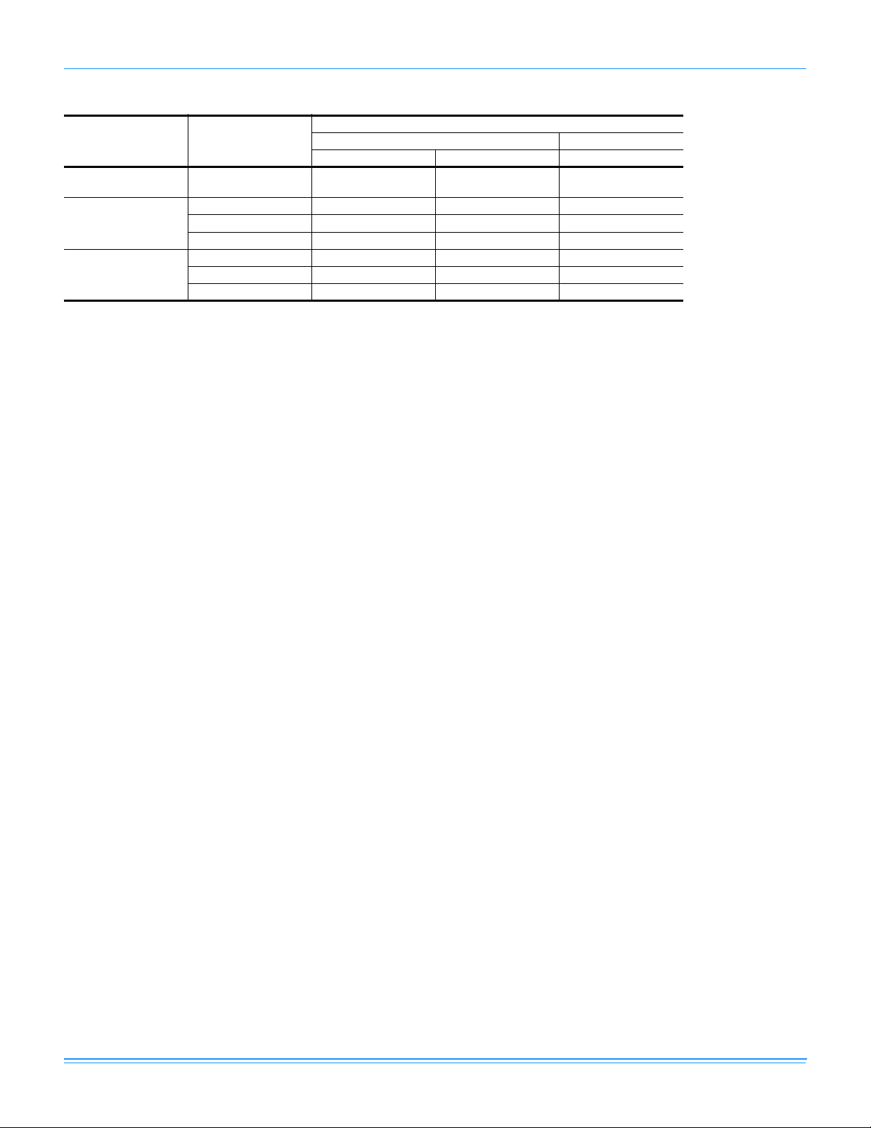
DNX Unit Limitations
718444-YTG-F-0214
Model
(Tons)
DNX024
(2.0)
DNX036
(3.0)
DNX048
(4.0)
Unit Limitations
Unit Voltage
208/230-1-60 187 252 115
208/230-1-60 187 252 115
208/230-3-60 187 252 115
460-3-60 432 504 115
208/230-1-60 187 252 115
208/230-3-60 187 252 115
460-3-60 432 504 115
Applied Voltage Outdoor DB Temp
Min Max Max (°F)
Johnson Controls Unitary Products 15
Page 16
718444-YTG-F-0214
Capacity Performance
DNZ024-060 Cooling Capacities
DNZ024 (2.0 Ton)
Air on
Evaporator Coil
CFM
WB
(°F)
77 29.9 1.6 4.7 4.0 2.1 - - - 26.9 1.8 9.1 7.4 5.3 - - -
500
72 28.3 1.6 11.7 9.7 7.7 5.8 - - 25.4 1.8 13.6 11.6 9.5 7.5 - 67 26.6 1.6 17.9 15.4 13.4 11.4 9.5 - 23.8 1.7 18.0 15.7 13.7 11.7 9.7 62 25.0 1.6 23.8 16.8 12.3 10.3 8.3 6.3 21.7 1.7 21.1 17.6 14.8 12.8 10.8 8.7
77 30.2 1.6 7.8 5.5 3.2 - - - 27.7 1.8 10.9 8.6 6.2 - - 72 28.5 1.6 14.7 12.4 10.1 7.9 - - 26.1 1.8 15.8 13.5 11.2 8.8 - -
600
67 26.9 1.6 21.6 19.3 17.0 14.8 12.5 - 24.6 1.8 20.7 18.4 16.1 13.7 11.4 62 25.3 1.6 24.5 19.9 16.0 13.8 11.5 9.2 22.4 1.7 22.0 19.7 17.4 15.0 12.7 10.4
57 26.4 1.6 26.4 22.0 18.2 15.9 13.7 11.4 23.7 1.7 23.7 21.5 19.2 16.8 14.5 12.2
77 30.5 1.6 10.8 7.0 4.4 - - - 28.5 1.8 12.6 9.8 7.2 - - 72 28.8 1.6 17.6 15.1 12.5 10.0 - - 26.9 1.8 18.0 15.4 12.8 10.2 - -
700
67 27.2 1.6 25.2 23.2 20.7 18.1 15.6 - 25.3 1.8 23.3 21.0 18.4 15.8 13.2 62 25.6 1.6 25.2 22.9 19.8 17.2 14.7 12.1 23.1 1.7 22.9 21.7 19.9 17.3 14.7 12.1
57 26.7 1.6 26.7 24.5 22.4 19.8 17.3 14.7 24.4 1.7 24.4 23.3 21.9 19.3 16.7 14.1
77 30.8 1.6 13.8 8.4 5.6 - - - 29.3 1.8 14.4 11.0 8.1 - - 72 29.1 1.6 20.6 17.8 14.9 12.1 - - 27.7 1.8 20.2 17.3 14.4 11.5 - -
800
67 27.4 1.6 27.4 27.1 24.3 21.5 18.6 - 26.0 1.8 26.0 23.6 20.8 17.9 15.0 62 25.9 1.6 25.9 25.9 23.5 20.7 17.9 15.0 23.7 1.7 23.7 23.7 22.4 19.5 16.6 13.7
57 27.0 1.6 27.0 27.0 26.6 23.7 20.9 18.1 25.1 1.8 25.1 25.1 24.7 21.8 19.0 16.1
72 30.0 1.6 20.4 17.1 13.8 10.5 - - 28.0 1.8 20.9 17.7 14.4 11.2 - -
900
67 28.2 1.6 28.2 26.2 22.9 19.5 16.2 - 26.4 1.8 26.4 24.0 20.8 17.5 14.2 62 26.6 1.6 26.6 26.6 23.5 20.2 16.9 13.6 24.0 1.7 24.0 24.0 22.4 19.2 15.9 12.7
57 27.8 1.6 27.8 27.8 26.5 23.2 19.9 16.6 25.4 1.8 25.4 25.4 24.7 21.5 18.2 15.0
72 30.8 1.6 20.1 16.4 12.6 8.8 - - 28.4 1.8 21.6 18.0 14.4 10.8 - -
1000
67 29.0 1.6 29.0 25.2 21.4 17.6 13.9 - 26.7 1.8 26.7 24.4 20.8 17.1 13.5 62 27.3 1.6 27.3 27.3 23.4 19.6 15.9 12.1 24.4 1.7 24.4 24.4 22.4 18.8 15.2 11.6
57 28.5 1.6 28.5 28.5 26.4 22.7 18.9 15.1 25.8 1.8 25.8 25.8 24.7 21.1 17.5 13.9
Net
Capacity
(MBh)
Total
1
Input
2
(kW)
Sensible Capacity (MBh)
Return Dry Bulb (°F) Return Dry Bulb (°F)
90 85 80 75 70 65 90 85 80 75 70 65
75°F
Temperature of Air on Condenser Coil
Net
1
Capacity
(MBh)
Total
Input
(kW)
Sensible Capacity (MBh)
2
85°F
16 Johnson Controls Unitary Products
Page 17

DNZ024 (2.0 Ton) (Continued)
Air on
Evaporator Coil
CFM
WB
(°F)
77 23.9 2.0 12.8 10.7 8.6 - - - 22.8 2.1 11.4 9.3 7.4 - - -
500
72 22.5 1.9 15.5 13.4 11.3 9.2 - - 20.8 2.1 14.3 12.2 10.2 8.1 - 67 21.1 1.9 18.2 16.1 14.0 11.9 9.9 - 18.7 2.0 17.3 15.2 12.9 10.8 8.7 62 18.5 1.9 18.5 18.5 17.4 15.3 13.2 11.1 17.0 2.0 17.0 17.0 15.1 13.0 11.0 8.9
77 25.2 2.0 14.0 11.6 9.3 - - - 24.0 2.1 13.5 10.5 8.1 - - 72 23.7 1.9 16.9 14.5 12.2 9.8 - - 21.8 2.1 16.0 13.5 11.1 8.7 - -
600
67 22.3 1.9 19.8 17.5 15.1 12.7 10.3 - 19.7 2.0 18.4 16.5 14.1 11.7 9.3 62 19.5 1.9 19.5 19.5 18.7 16.3 13.9 11.6 17.8 2.0 17.8 17.8 16.6 14.1 11.7 9.3
57 21.0 1.9 21.0 21.0 20.1 17.7 15.4 13.0 19.1 2.0 19.1 19.1 17.7 15.2 12.8 10.4
77 26.5 2.0 15.2 12.6 9.9 - - - 25.1 2.1 15.6 11.8 8.8 - - 72 24.9 1.9 18.3 15.7 13.0 10.4 - - 22.9 2.1 17.6 14.8 12.1 9.4 - -
700
67 23.4 1.9 21.5 18.8 16.1 13.5 10.8 - 20.6 2.0 19.6 17.9 15.4 12.6 9.9 62 20.5 1.9 20.5 20.5 20.0 17.3 14.7 12.0 18.7 2.0 18.7 18.7 18.0 15.2 12.5 9.8
57 22.1 1.9 22.1 22.1 21.5 18.8 16.2 13.5 20.0 2.0 20.0 20.0 19.2 16.4 13.7 10.9
77 27.8 2.0 16.4 13.5 10.6 - - - 26.3 2.1 17.7 13.0 9.5 - - 72 26.2 1.9 19.8 16.8 13.9 10.9 - - 23.9 2.1 19.2 16.2 13.1 10.0 - -
800
67 24.6 1.9 23.1 20.1 17.2 14.3 11.3 - 21.5 2.1 20.8 19.3 16.6 13.5 10.5 62 21.5 1.9 21.5 21.5 21.3 18.4 15.4 12.5 19.5 2.0 19.5 19.5 19.4 16.4 13.3 10.2
57 23.2 1.9 23.2 23.2 22.9 20.0 17.0 14.1 21.0 2.0 21.0 21.0 20.7 17.6 14.5 11.5
72 26.1 2.0 21.5 18.3 15.0 11.8 - - 24.0 2.1 20.7 17.4 14.0 10.7 - -
900
67 24.5 1.9 23.8 21.9 18.7 15.4 12.2 - 21.7 2.1 21.3 20.3 17.8 14.5 11.2 62 21.5 1.9 21.5 21.5 21.4 18.2 14.9 11.7 19.7 2.0 19.7 19.7 19.6 16.3 12.9 9.6
57 23.1 1.9 23.1 23.1 23.0 19.8 16.6 13.4 21.1 2.1 21.1 21.1 21.0 17.6 14.3 11.0
72 26.1 2.0 23.2 19.7 16.2 12.8 - - 24.2 2.1 22.2 18.6 15.0 11.4 - -
1000
67 24.5 1.9 24.5 23.6 20.1 16.6 13.2 - 21.8 2.1 21.8 21.3 19.1 15.5 11.9 62 21.4 1.9 21.4 21.4 21.4 18.0 14.5 11.0 19.8 2.1 19.8 19.8 19.8 16.2 12.6 9.0
57 23.1 1.9 23.1 23.1 23.1 19.6 16.1 12.7 21.2 2.1 21.2 21.2 21.2 17.6 14.0 10.4
Net
Capacity
(MBh)
Total
1
Input
(kW)
718444-YTG-F-0214
Sensible Capacity (MBh)
2
90 85 80 75 70 65 90 85 80 75 70 65
Return Dry Bulb (°F) Return Dry Bulb (°F)
95°F
Temperature of Air on Condenser Coil
Net
1
Capacity
(MBh)
Total
Input
(kW)
Sensible Capacity (MBh)
2
105°F
Johnson Controls Unitary Products 17
Page 18
718444-YTG-F-0214
DNZ024 (2.0 Ton) (Continued)
Air on
Evaporator Coil
CFM
500
600
700
800
900
1000
WB
(°F)
77
72
67
62
77
72
67
62
57
77
72
67
62
57
77
72
67
62
57
72
67
62
57
72
67
62
57
Net
Capacity
(MBh)
Total
1
Input
2
(kW)
21.8 2.3 10.0 7.9 6.2 - - - 20.8 2.4 10.0 5.9 5.1 - - -
19.1 2.2 13.2 11.1 9.0 6.9 - - 17.4 2.4 12.0 9.9 7.8 5.8 - -
16.3 2.2 16.3 14.2 11.8 9.7 7.6 - 14.0 2.3 14.0 14.0 10.6 8.5 6.5 -
15.5 2.2 15.5 15.5 12.9 10.8 8.7 6.6 14.0 2.3 14.0 14.0 10.6 8.5 6.5 4.4
22.8 2.3 13.0 9.5 7.0 - - - 21.6 2.4 13.7 8.6 5.9 - - -
19.9 2.2 15.0 12.5 10.1 7.6 - - 18.0 2.4 14.1 11.6 9.1 6.5 - -
17.1 2.2 17.1 15.6 13.2 10.7 8.3 - 14.5 2.3 14.5 14.5 12.2 9.7 7.2 -
16.2 2.2 16.2 16.2 14.4 12.0 9.5 7.1 14.6 2.3 14.6 14.6 12.3 9.8 7.3 4.8
17.3 2.2 17.3 17.3 15.2 12.8 10.3 7.8 15.5 2.3 15.5 15.5 12.8 10.3 7.8 5.3
23.8 2.3 15.9 11.0 7.8 - - - 22.4 2.5 17.3 11.4 6.7 - - -
20.8 2.2 16.9 14.0 11.2 8.3 - - 18.7 2.4 16.1 13.2 10.3 7.3 - -
17.8 2.2 17.8 17.1 14.6 11.8 8.9 - 15.0 2.3 15.0 15.0 13.8 10.9 8.0 -
16.9 2.2 16.9 16.9 16.0 13.2 10.3 7.5 15.1 2.3 15.1 15.1 14.0 11.1 8.2 5.2
18.0 2.2 18.0 18.0 16.9 14.0 11.2 8.4 16.0 2.3 16.0 16.0 14.5 11.6 8.7 5.8
24.7 2.3 18.9 12.5 8.5 - - - 23.2 2.5 20.9 14.2 7.5 - - -
21.6 2.3 18.7 15.5 12.3 9.1 - - 19.3 2.4 18.2 14.8 11.5 8.1 - -
18.5 2.2 18.5 18.5 16.0 12.8 9.6 - 15.5 2.3 15.5 15.5 15.5 12.1 8.8 -
17.6 2.2 17.6 17.6 17.6 14.3 11.1 7.9 15.6 2.3 15.6 15.6 15.6 12.3 9.0 5.6
18.8 2.2 18.8 18.8 18.5 15.3 12.1 8.9 16.5 2.4 16.5 16.5 16.3 13.0 9.6 6.3
22.0 2.3 20.0 16.5 13.0 9.6 - - 19.9 2.4 19.2 15.6 12.0 8.4 - -
18.8 2.2 18.8 18.8 17.0 13.6 10.1 - 15.9 2.4 15.9 15.9 15.9 12.6 9.0 -
17.8 2.2 17.8 17.8 17.8 14.4 10.9 7.5 16.0 2.3 16.0 16.0 16.0 12.5 8.9 5.3
19.1 2.2 19.1 19.1 18.9 15.5 12.0 8.5 17.0 2.4 17.0 17.0 16.9 13.3 9.7 6.1
22.3 2.3 21.2 17.5 13.8 10.1 - - 20.4 2.4 20.3 16.4 12.6 8.8 - -
19.1 2.2 19.1 19.1 18.0 14.3 10.6 - 16.4 2.4 16.4 16.4 16.4 13.2 9.3 -
18.1 2.2 18.1 18.1 18.1 14.4 10.7 7.0 16.5 2.4 16.5 16.5 16.5 12.7 8.8 5.0
19.4 2.2 19.4 19.4 19.4 15.7 11.9 8.2 17.5 2.4 17.5 17.5 17.5 13.7 9.9 6.0
Sensible Capacity (MBh)
Return Dry Bulb (°F) Return Dry Bulb (°F)
90 85 80 75 70 65 90 85 80 75 70 65
115°F
1. These capacities are Net Capacities.
2. These ratings include the compressor, condenser fan and supply air blower motors.
Temperature of Air on Condenser Coil
Net
Capacity
(MBh)
Total
1
Input
2
(kW)
Sensible Capacity (MBh)
125°F
18 Johnson Controls Unitary Products
Page 19

DNZ030 (2.5 Ton)
Air on
Evaporator Coil
Capacity
CFM
850
900
950
1000
1125
1250
850
900
950
1000
1125
1250
WB
(°F)
77
72
67
62
57
77
72
67
62
57
77
72
67
62
57
72
67
62
57
72
67
62
57
72
67
62
57
77
72
67
62
57
77
72
67
62
57
77
72
67
62
57
72
67
62
57
72
67
62
57
72
67
62
57
718444-YTG-F-0214
Net
(MBh)
Total
1
Input
2
(kW)
Sensible Capacity (MBh)
Return Dry Bulb (°F) Return Dry Bulb (°F)
90 85 80 75 70 65 90 85 80 75 70 65
75°F 85°F
35.3 2.1 15.9 12.6 9.3 - - - 33.9 2.3 16.5 13.1 9.7 - - -
33.5 2.1 20.8 17.5 14.2 10.8 - - 31.7 2.3 20.8 17.5 14.1 10.7 - -
31.6 2.1 25.7 22.4 19.0 15.7 12.4 - 29.6 2.3 25.2 21.8 18.4 15.0 11.6 -
29.7 2.0 29.7 27.6 22.8 19.5 16.1 12.8 27.4 2.2 27.4 26.3 22.4 19.0 15.6 12.2
37.1 2.1 17.0 13.7 10.4 - - - 35.6 2.4 17.6 14.2 10.7 - - -
35.1 2.1 22.4 19.1 15.8 12.4 - - 33.3 2.3 22.4 18.9 15.5 12.0 - -
33.2 2.1 27.8 24.5 21.2 17.8 14.5 - 31.1 2.3 27.2 23.7 20.3 16.8 13.3 -
31.2 2.0 31.2 29.8 25.3 22.0 18.7 15.4 28.8 2.2 28.8 28.1 24.6 21.2 17.7 14.3
29.9 2.0 29.9 29.9 27.1 23.8 20.5 17.2 28.0 2.2 28.0 28.0 25.8 22.4 18.9 15.5
38.8 2.1 18.0 14.7 11.4 - - - 37.3 2.4 18.8 15.2 11.7 - - -
36.8 2.1 24.0 20.7 17.3 14.0 - - 34.9 2.3 24.0 20.4 16.9 13.4 - -
34.8 2.1 29.9 26.6 23.3 20.0 16.7 - 32.5 2.3 29.1 25.6 22.1 18.6 15.1 -
32.7 2.1 32.7 32.0 27.9 24.6 21.3 17.9 30.2 2.3 30.2 29.8 26.9 23.4 19.8 16.3
31.3 2.1 31.3 31.3 29.9 26.6 23.2 19.9 29.4 2.3 29.4 29.4 28.2 24.7 21.2 17.6
40.6 2.2 19.1 15.8 12.5 - - - 39.0 2.4 19.9 16.3 12.7 - - -
38.5 2.1 25.6 22.2 18.9 15.6 - - 36.5 2.3 25.5 21.9 18.3 14.7 - -
36.4 2.1 32.0 28.7 25.4 22.1 18.8 - 34.0 2.3 31.1 27.6 24.0 20.4 16.8 -
34.2 2.1 34.2 34.2 30.4 27.1 23.8 20.5 31.5 2.3 31.5 31.5 29.1 25.6 22.0 18.4
32.8 2.1 32.8 32.8 32.6 29.3 26.0 22.7 30.7 2.3 30.7 30.7 30.6 27.0 23.4 19.8
39.1 2.1 26.5 22.9 19.4 15.8 - - 37.1 2.4 26.9 23.0 19.2 15.3 - -
37.0 2.1 34.1 29.6 26.0 22.4 18.9 - 34.6 2.3 32.8 28.9 25.1 21.2 17.4 -
34.7 2.1 34.7 34.7 32.1 28.6 25.0 21.5 32.0 2.3 32.0 32.0 30.5 26.6 22.8 18.9
33.3 2.1 33.3 33.3 33.2 29.7 26.1 22.5 31.2 2.3 31.2 31.2 31.1 27.3 23.4 19.6
39.8 2.2 27.4 23.6 19.8 16.0 - - 37.7 2.4 28.2 24.1 20.0 15.9 - -
37.6 2.1 36.1 30.4 26.6 22.8 19.0 - 35.1 2.3 34.4 30.3 26.2 22.0 17.9 -
35.3 2.1 35.3 35.3 33.8 30.0 26.2 22.4 32.5 2.3 32.5 32.5 31.8 27.7 23.6 19.5
33.8 2.1 33.8 33.8 33.8 30.0 26.2 22.4 31.7 2.3 31.7 31.7 31.7 27.6 23.5 19.4
95°F 105°F
32.4 2.6 17.1 13.7 10.2 - - - 30.7 2.8 17.4 13.0 9.4 - - -
30.0 2.5 20.9 17.4 14.0 10.5 - - 27.8 2.7 20.4 16.8 13.1 9.5 - -
27.5 2.5 24.7 21.2 17.8 14.3 10.8 - 24.9 2.6 23.5 20.6 16.9 13.2 9.6 -
25.1 2.4 25.1 25.1 21.9 18.5 15.0 11.6 23.0 2.6 23.0 23.0 20.1 16.4 12.8 9.1
34.1 2.6 18.3 14.7 11.1 - - - 32.1 2.8 18.8 14.0 10.2 - - -
31.5 2.5 22.4 18.8 15.2 11.6 - - 29.1 2.7 21.8 18.1 14.3 10.6 - -
28.9 2.5 26.5 22.9 19.3 15.8 12.2 - 26.1 2.7 24.9 22.2 18.4 14.7 10.9 -
26.4 2.4 26.4 26.4 23.9 20.3 16.7 13.1 24.1 2.6 24.1 24.1 21.9 18.2 14.4 10.7
26.2 2.4 26.2 26.2 24.5 20.9 17.3 13.8 24.0 2.6 24.0 24.0 22.2 18.4 14.7 10.9
35.7 2.6 19.5 15.8 12.0 - - - 33.4 2.8 20.2 14.9 11.1 - - -
33.0 2.5 23.9 20.2 16.5 12.8 - - 30.3 2.7 23.2 19.4 15.5 11.7 - -
30.3 2.5 28.4 24.7 20.9 17.2 13.5 - 27.2 2.7 26.2 23.8 20.0 16.2 12.3 -
27.6 2.4 27.6 27.6 25.9 22.1 18.4 14.7 25.1 2.6 25.1 25.1 23.7 19.9 16.1 12.2
27.4 2.4 27.4 27.4 26.5 22.8 19.1 15.4 25.0 2.6 25.0 25.0 24.0 20.2 16.3 12.5
37.4 2.6 20.7 16.8 12.9 - - - 34.8 2.8 21.6 15.9 11.9 - - -
34.6 2.6 25.5 21.6 17.7 13.9 - - 31.6 2.8 24.6 20.7 16.7 12.8 - -
31.7 2.5 30.3 26.4 22.5 18.7 14.8 - 28.3 2.7 27.6 25.5 21.5 17.6 13.7 -
28.9 2.5 28.9 28.9 27.8 24.0 20.1 16.2 26.1 2.6 26.1 26.1 25.6 21.7 17.7 13.8
28.7 2.5 28.7 28.7 28.6 24.7 20.8 17.0 26.0 2.6 26.0 26.0 25.9 21.9 18.0 14.1
35.1 2.6 27.3 23.1 19.0 14.8 - - 32.1 2.8 26.4 22.1 17.9 13.6 - -
32.2 2.5 31.5 28.3 24.1 20.0 15.8 - 28.8 2.7 28.4 26.7 23.0 18.8 14.5 -
29.3 2.5 29.3 29.3 28.8 24.7 20.5 16.4 26.5 2.7 26.5 26.5 26.3 22.0 17.8 13.5
29.1 2.5 29.1 29.1 29.1 24.9 20.8 16.6 26.5 2.7 26.5 26.5 26.4 22.1 17.9 13.6
35.6 2.6 29.1 24.7 20.2 15.8 - - 32.6 2.8 28.2 23.6 19.0 14.5 - -
32.7 2.5 32.7 30.1 25.7 21.3 16.9 - 29.2 2.7 29.2 28.0 24.5 19.9 15.4 -
29.8 2.5 29.8 29.8 29.8 25.4 21.0 16.5 27.0 2.7 27.0 27.0 27.0 22.4 17.8 13.2
29.6 2.5 29.6 29.6 29.6 25.2 20.7 16.3 26.9 2.7 26.9 26.9 26.9 22.3 17.7 13.1
Temperature of Air on Condenser Coil
Net
1
Capacity
(MBh)
Total
Input
(kW)
Sensible Capacity (MBh)
2
Johnson Controls Unitary Products 19
Page 20
718444-YTG-F-0214
DNZ030 (2.5 Ton) (Continued)
Air on
Evaporator Coil
CFM
850
900
950
1000
1125
1250
WB
(°F)
77
72
67
62
57
77
72
67
62
57
77
72
67
62
57
72
67
62
57
72
67
62
57
72
67
62
57
Net
Capacity
(MBh)
Total
1
Input
2
(kW)
29.0 3.0 17.6 12.4 8.5 - - - 27.2 3.3 19.3 11.2 7.7 - - -
25.7 2.9 20.0 16.1 12.3 8.4 - - 23.5 3.1 19.6 15.5 11.4 7.4 - -
22.4 2.8 22.4 19.9 16.0 12.2 8.3 - 19.8 3.0 19.8 19.8 15.2 11.1 7.1 -
21.0 2.8 21.0 21.0 18.2 14.3 10.5 6.6 18.9 3.0 18.9 18.9 16.3 12.3 8.2 4.1
30.0 3.0 19.3 13.2 9.3 - - - 28.0 3.3 21.0 12.8 8.4 - - -
26.6 2.9 21.2 17.3 13.4 9.5 - - 24.2 3.1 20.7 16.6 12.5 8.5 - -
23.2 2.8 23.2 21.5 17.6 13.6 9.7 - 20.4 3.0 20.4 20.4 16.7 12.6 8.5 -
21.8 2.8 21.8 21.8 19.9 16.0 12.1 8.2 19.5 3.0 19.5 19.5 17.9 13.8 9.8 5.7
21.8 2.8 21.8 21.8 19.8 15.9 12.0 8.1 19.6 3.0 19.6 19.6 17.4 13.3 9.3 5.2
31.1 3.0 20.9 14.1 10.1 - - - 28.8 3.3 22.6 14.5 9.1 - - -
27.6 2.9 22.5 18.5 14.6 10.6 - - 24.9 3.2 21.8 17.7 13.6 9.6 - -
24.1 2.9 24.1 23.0 19.1 15.1 11.2 - 20.9 3.0 20.9 20.9 18.1 14.1 10.0 -
22.5 2.8 22.5 22.5 21.6 17.7 13.7 9.8 20.0 3.0 20.0 20.0 19.5 15.4 11.4 7.3
22.6 2.8 22.6 22.6 21.5 17.5 13.6 9.6 20.1 3.0 20.1 20.1 18.9 14.9 10.8 6.7
32.2 3.1 22.6 14.9 10.9 - - - 29.6 3.3 24.2 16.1 9.9 - - -
28.6 3.0 23.7 19.7 15.7 11.7 - - 25.5 3.2 22.9 18.8 14.7 10.7 - -
24.9 2.9 24.9 24.6 20.6 16.6 12.6 - 21.5 3.0 21.5 21.5 19.6 15.5 11.5 -
23.3 2.8 23.3 23.3 23.3 19.3 15.3 11.3 20.5 3.0 20.5 20.5 20.5 17.0 12.9 8.9
23.4 2.8 23.4 23.4 23.2 19.2 15.2 11.2 20.7 3.0 20.7 20.7 20.5 16.4 12.4 8.3
29.1 3.0 25.5 21.2 16.8 12.4 - - 26.1 3.2 24.7 20.2 15.7 11.2 - -
25.3 2.9 25.3 25.2 21.9 17.6 13.2 - 21.9 3.1 21.9 21.9 20.9 16.4 11.9 -
23.7 2.8 23.7 23.7 23.7 19.4 15.0 10.6 21.0 3.0 21.0 21.0 21.0 16.7 12.2 7.7
23.8 2.9 23.8 23.8 23.7 19.3 14.9 10.6 21.1 3.0 21.1 21.1 21.0 16.5 12.0 7.5
29.6 3.0 27.4 22.6 17.8 13.1 - - 26.6 3.2 26.5 21.6 16.6 11.7 - -
25.8 2.9 25.8 25.8 23.3 18.6 13.8 - 22.4 3.1 22.4 22.4 22.1 17.2 12.3 -
24.2 2.9 24.2 24.2 24.2 19.4 14.7 9.9 21.4 3.1 21.4 21.4 21.4 16.4 11.5 6.6
24.2 2.9 24.2 24.2 24.2 19.5 14.7 9.9 21.5 3.1 21.5 21.5 21.5 16.6 11.7 6.7
Sensible Capacity (MBh)
Return Dry Bulb (°F) Return Dry Bulb (°F)
90 85 80 75 70 65 90 85 80 75 70 65
115°F 125°F
1. These capacities are Net Capacities.
2. These ratings include the compressor, condenser fan and supply air blower motors.
Temperature of Air on Condenser Coil
Net
Capacity
(MBh)
Total
1
Input
2
(kW)
Sensible Capacity (MBh)
20 Johnson Controls Unitary Products
Page 21

DNZ036 (3.0 Ton)
Air on
Evaporator Coil
Capacity
CFM
750
900
1050
1200
1350
1500
750
900
1050
1200
1350
1500
WB
(°F)
77
72
67
62
77
72
67
62
57
77
72
67
62
57
77
72
67
62
57
72
67
62
57
72
67
62
57
77
72
67
62
77
72
67
62
57
77
72
67
62
57
77
72
67
62
57
72
67
62
57
72
67
62
57
718444-YTG-F-0214
Net
(MBh)
Total
1
Input
2
(kW)
Sensible Capacity (MBh)
Return Dry Bulb (°F) Return Dry Bulb (°F)
90 85 80 75 70 65 90 85 80 75 70 65
75°F 85°F
36.9 1.9 18.9 15.2 12.1 - - - 40.3 2.5 18.3 15.2 12.1 - - -
34.7 2.0 22.9 19.8 16.7 13.6 - - 37.1 2.5 23.2 20.0 16.8 13.7 - -
32.6 2.1 26.9 24.4 21.3 18.2 15.1 - 33.9 2.5 28.1 24.8 21.6 18.4 15.2 -
30.7 2.0 30.7 30.7 26.4 23.3 20.2 17.1 31.3 2.5 31.3 30.7 25.7 22.5 19.3 16.2
39.2 1.9 20.6 17.0 13.4 - - - 41.4 2.4 20.5 16.8 13.2 - - -
36.8 2.0 25.6 22.0 18.5 14.9 - - 38.1 2.5 25.7 22.1 18.4 14.7 - -
34.5 2.2 30.7 27.1 23.5 19.9 16.3 - 34.8 2.5 30.9 27.3 23.6 19.9 16.2 -
32.4 2.0 32.4 32.4 29.2 25.6 22.0 18.4 32.1 2.5 32.1 31.7 28.0 24.4 20.7 17.0
32.7 2.1 32.7 32.7 29.7 26.1 22.5 19.0 32.7 2.5 32.7 32.3 28.7 25.0 21.3 17.6
41.4 2.0 22.2 18.8 14.7 - - - 42.4 2.4 22.8 18.5 14.3 - - -
38.9 2.1 28.4 24.3 20.2 16.1 - - 39.1 2.5 28.3 24.1 19.9 15.7 - -
36.4 2.2 34.5 29.8 25.7 21.7 17.6 - 35.7 2.5 33.7 29.7 25.6 21.4 17.2 -
34.2 2.1 34.2 34.2 31.9 27.8 23.7 19.7 32.9 2.5 32.9 32.7 30.4 26.2 22.0 17.9
34.5 2.1 34.5 34.5 32.5 28.4 24.4 20.3 33.5 2.5 33.5 33.3 31.1 26.9 22.7 18.5
43.7 2.0 23.8 20.5 15.9 - - - 43.5 2.4 25.1 20.1 15.4 - - -
41.0 2.1 31.1 26.5 22.0 17.4 - - 40.0 2.5 30.8 26.1 21.5 16.8 - -
38.4 2.2 38.4 32.6 28.0 23.4 18.8 - 36.6 2.5 36.6 32.2 27.5 22.9 18.2 -
36.0 2.1 36.0 36.0 34.6 30.1 25.5 20.9 33.8 2.5 33.8 33.8 32.7 28.1 23.4 18.7
36.3 2.1 36.3 36.3 35.3 30.7 26.2 21.6 34.3 2.5 34.3 34.3 33.5 28.8 24.1 19.4
41.7 2.1 33.3 28.1 22.8 17.6 - - 40.2 2.5 32.5 27.2 22.0 16.7 - -
39.0 2.2 39.0 34.3 29.1 23.9 18.7 - 36.8 2.5 36.8 33.4 28.2 22.9 17.7 -
36.5 2.0 36.5 36.5 35.9 30.7 25.4 20.2 33.9 2.5 33.9 33.9 33.4 28.2 22.9 17.7
36.9 2.1 36.9 36.9 36.4 31.2 25.9 20.7 34.5 2.5 34.5 34.5 34.1 28.8 23.6 18.3
42.4 2.0 35.5 29.6 23.7 17.9 - - 40.5 2.5 34.1 28.3 22.5 16.7 - -
39.6 2.1 39.6 36.1 30.2 24.4 18.5 - 37.0 2.5 37.0 34.7 28.9 23.0 17.2 -
37.1 2.0 37.1 37.1 37.1 31.3 25.4 19.5 34.1 2.5 34.1 34.1 34.1 28.3 22.5 16.6
37.4 2.0 37.4 37.4 37.4 31.6 25.7 19.8 34.7 2.5 34.7 34.7 34.7 28.9 23.1 17.2
95°F 105°F
43.7 3.0 17.6 15.2 12.0 - - - 40.0 3.3 16.0 14.3 11.1 - - -
39.4 2.9 23.5 20.2 16.9 13.7 - - 36.2 3.3 22.5 19.2 15.9 12.7 - -
35.1 2.9 29.4 25.2 21.9 18.6 15.4 - 32.5 3.3 29.0 24.1 20.7 17.5 14.2 -
31.9 3.0 31.9 30.2 24.9 21.7 18.4 15.2 30.0 3.4 30.0 28.9 23.4 20.1 16.8 13.6
43.6 3.0 20.5 16.7 12.9 - - - 39.7 3.3 19.5 15.7 12.0 - - -
39.3 2.9 25.8 22.1 18.3 14.5 - - 36.0 3.3 24.7 20.9 17.2 13.4 - -
35.0 2.8 31.2 27.4 23.6 19.9 16.1 - 32.2 3.3 29.9 26.2 22.4 18.6 14.9 -
31.8 3.0 31.8 30.7 26.9 23.1 19.4 15.6 29.8 3.4 29.8 29.0 25.3 21.5 17.7 14.0
32.6 3.0 32.6 31.4 27.6 23.9 20.1 16.3 30.6 3.4 30.6 29.5 25.8 22.0 18.3 14.5
43.4 2.9 23.4 18.2 13.9 - - - 39.4 3.3 23.0 17.2 12.9 - - -
39.2 2.9 28.2 23.9 19.6 15.3 - - 35.7 3.3 26.9 22.7 18.5 14.2 - -
34.9 2.8 33.0 29.6 25.4 21.1 16.8 - 32.0 3.3 30.8 28.2 24.0 19.8 15.6 -
31.6 3.0 31.6 31.1 28.9 24.6 20.3 16.1 29.5 3.4 29.5 29.2 27.1 22.9 18.6 14.4
32.5 2.9 32.5 31.9 29.6 25.4 21.1 16.8 30.4 3.4 30.4 29.8 27.7 23.4 19.2 15.0
43.3 2.9 26.3 19.6 14.8 - - - 39.1 3.3 26.6 18.6 13.8 - - -
39.0 2.8 30.5 25.7 21.0 16.2 - - 35.4 3.3 29.2 24.4 19.7 15.0 - -
34.8 2.7 34.8 31.9 27.1 22.3 17.5 - 31.8 3.3 31.8 30.3 25.7 21.0 16.3 -
31.5 2.9 31.5 31.5 30.8 26.1 21.3 16.5 29.3 3.4 29.3 29.3 29.0 24.3 19.5 14.8
32.4 2.9 32.4 32.4 31.7 26.9 22.1 17.3 30.1 3.4 30.1 30.1 29.6 24.8 20.1 15.4
38.8 2.9 31.7 26.4 21.1 15.8 - - 35.3 3.3 30.5 25.3 20.0 14.8 - -
34.5 2.8 34.5 32.6 27.3 22.0 16.7 - 31.6 3.3 31.6 30.7 26.1 20.8 15.6 -
31.3 3.0 31.3 31.3 31.0 25.7 20.4 15.1 29.2 3.4 29.2 29.2 29.1 23.8 18.6 13.3
32.2 2.9 32.2 32.2 31.8 26.5 21.3 16.0 30.0 3.4 30.0 30.0 29.7 24.5 19.3 14.0
38.5 2.9 32.8 27.0 21.3 15.5 - - 35.2 3.3 31.9 26.1 20.3 14.5 - -
34.3 2.9 34.3 33.3 27.5 21.7 15.9 - 31.5 3.3 31.5 31.0 26.5 20.7 14.9 -
31.1 3.0 31.1 31.1 31.1 25.3 19.6 13.8 29.1 3.5 29.1 29.1 29.1 23.4 17.6 11.8
32.0 3.0 32.0 32.0 32.0 26.2 20.4 14.6 29.9 3.4 29.9 29.9 29.9 24.2 18.4 12.6
Temperature of Air on Condenser Coil
Net
1
Capacity
(MBh)
Total
Input
(kW)
Sensible Capacity (MBh)
2
Johnson Controls Unitary Products 21
Page 22
718444-YTG-F-0214
DNZ036 (3.0 Ton) (Continued)
Air on
Evaporator Coil
CFM
750
900
1050
1200
1350
1500
WB
(°F)
77
72
67
62
77
72
67
62
57
77
72
67
62
57
77
72
67
62
57
72
67
62
57
72
67
62
57
Net
Capacity
(MBh)
Total
1
Input
2
(kW)
36.2 3.6 14.4 13.4 10.2 - - - 32.4 3.9 13.9 11.7 9.3 - - -
33.0 3.7 21.5 18.2 14.9 11.6 - - 29.8 4.1 20.5 17.2 13.9 10.6 - -
29.8 3.8 28.6 23.0 19.6 16.3 13.0 - 27.1 4.2 27.1 21.9 18.4 15.1 11.8 -
28.1 3.8 28.1 27.5 21.8 18.6 15.3 12.0 26.2 4.3 26.2 26.1 20.3 17.0 13.7 10.4
35.8 3.6 18.5 14.8 11.0 - - - 31.9 4.0 18.3 13.8 10.1 - - -
32.6 3.7 23.6 19.8 16.1 12.4 - - 29.3 4.1 22.5 18.7 15.0 11.3 - -
29.4 3.8 28.6 24.9 21.2 17.4 13.7 - 26.6 4.3 26.6 23.7 19.9 16.2 12.5 -
27.8 3.9 27.8 27.3 23.6 19.9 16.1 12.4 25.8 4.3 25.8 25.7 21.9 18.2 14.5 10.8
28.5 3.8 28.5 27.6 23.9 20.2 16.4 12.7 26.5 4.2 26.5 25.8 22.0 18.3 14.6 10.9
35.4 3.7 22.7 16.2 11.9 - - - 31.3 4.1 22.7 15.9 10.9 - - -
32.2 3.8 25.7 21.5 17.3 13.1 - - 28.7 4.2 24.4 20.3 16.1 12.0 - -
29.1 3.8 28.7 26.8 22.7 18.5 14.3 - 26.2 4.4 26.2 25.4 21.4 17.3 13.1 -
27.4 3.9 27.4 27.2 25.4 21.2 17.0 12.8 25.3 4.4 25.3 25.3 23.6 19.4 15.3 11.1
28.2 3.8 28.2 27.7 25.7 21.5 17.3 13.1 26.0 4.3 26.0 25.7 23.7 19.5 15.4 11.2
34.9 3.7 26.9 17.6 12.7 - - - 30.8 4.1 27.1 18.0 11.6 - - -
31.8 3.8 27.8 23.1 18.5 13.8 - - 28.2 4.3 26.4 21.8 17.3 12.7 - -
28.7 3.9 28.7 28.7 24.3 19.7 15.0 - 25.7 4.4 25.7 25.7 22.9 18.3 13.8 -
27.1 3.9 27.1 27.1 27.1 22.5 17.8 13.2 24.9 4.4 24.9 24.9 24.9 20.7 16.1 11.5
27.8 3.9 27.8 27.8 27.5 22.8 18.2 13.5 25.6 4.4 25.6 25.6 25.4 20.8 16.2 11.6
31.9 3.8 29.3 24.1 18.9 13.7 - - 28.4 4.2 28.2 23.0 17.8 12.7 - -
28.8 3.9 28.8 28.8 24.9 19.7 14.5 - 25.9 4.4 25.9 25.9 23.7 18.5 13.3 -
27.1 3.9 27.1 27.1 27.1 21.9 16.7 11.5 25.0 4.4 25.0 25.0 25.0 20.0 14.9 9.7
27.9 3.8 27.9 27.9 27.7 22.5 17.3 12.0 25.7 4.3 25.7 25.7 25.6 20.4 15.3 10.1
31.9 3.7 30.9 25.1 19.4 13.6 - - 28.6 4.2 28.6 24.2 18.4 12.6 - -
28.8 3.8 28.8 28.8 25.4 19.7 13.9 - 26.0 4.3 26.0 26.0 24.4 18.6 12.9 -
27.1 3.9 27.1 27.1 27.1 21.4 15.6 9.8 25.2 4.3 25.2 25.2 25.2 19.4 13.6 7.9
27.9 3.8 27.9 27.9 27.9 22.1 16.3 10.6 25.8 4.3 25.8 25.8 25.8 20.1 14.3 8.5
Sensible Capacity (MBh)
Return Dry Bulb (°F) Return Dry Bulb (°F)
90 85 80 75 70 65 90 85 80 75 70 65
115°F 125°F
1. These capacities are Net Capacities.
2. These ratings include the compressor, condenser fan and supply air blower motors.
Temperature of Air on Condenser Coil
Net
Capacity
(MBh)
Total
1
Input
2
(kW)
Sensible Capacity (MBh)
22 Johnson Controls Unitary Products
Page 23

DNZ042 (3.5 Ton)
Air on
Evaporator Coil
Capacity
CFM
875
1050
1225
1400
1515
1630
875
1050
1225
1400
1515
1630
WB
(°F)
77
72
67
62
57
77
72
67
62
57
77
72
67
62
57
72
67
62
57
72
67
62
57
72
67
62
57
77
72
67
62
57
77
72
67
62
57
77
72
67
62
57
72
67
62
57
72
67
62
57
72
67
62
57
718444-YTG-F-0214
Net
(MBh)
Total
1
Input
2
(kW)
Sensible Capacity (MBh)
Return Dry Bulb (°F) Return Dry Bulb (°F)
90 85 80 75 70 65 90 85 80 75 70 65
75°F 85°F
46.4 2.7 21.7 16.7 12.9 - - - 45.8 2.9 20.8 16.8 12.9 - - -
44.6 2.6 27.5 23.6 19.8 15.9 - - 42.9 2.9 27.0 23.1 19.1 15.2 - -
42.8 2.6 33.3 30.5 26.7 22.8 18.9 - 39.9 2.9 33.2 29.3 25.4 21.5 17.5 -
39.1 2.5 39.1 39.1 32.1 28.2 24.4 20.5 36.5 2.8 36.5 36.5 30.4 26.4 22.5 18.6
48.9 2.7 23.1 18.7 14.3 - - - 48.1 3.0 23.4 18.9 14.4 - - -
47.0 2.7 30.8 26.4 22.0 17.6 - - 45.0 2.9 30.4 25.9 21.4 16.8 - -
45.0 2.6 38.5 34.1 29.7 25.3 20.9 - 41.9 2.9 37.3 32.8 28.3 23.8 19.3 -
41.2 2.6 41.2 41.2 35.8 31.4 27.0 22.6 38.4 2.8 38.4 38.4 33.9 29.4 24.8 20.3
40.1 2.5 40.1 40.1 36.4 32.0 27.6 23.2 37.5 2.8 37.5 37.5 33.7 29.2 24.7 20.2
51.4 2.7 24.5 20.7 15.8 - - - 50.4 3.0 26.1 21.0 15.9 - - -
49.3 2.7 34.1 29.2 24.3 19.4 - - 47.2 2.9 33.8 28.7 23.6 18.5 - -
47.3 2.6 43.6 37.6 32.7 27.8 22.9 - 43.9 2.9 41.4 36.4 31.3 26.2 21.1 -
43.3 2.6 43.3 43.3 39.4 34.5 29.6 24.7 40.2 2.8 40.2 40.2 37.4 32.3 27.2 22.1
42.1 2.6 42.1 42.1 40.1 35.2 30.3 25.4 39.3 2.8 39.3 39.3 37.2 32.2 27.1 22.0
53.8 2.7 25.9 22.7 17.3 - - - 52.7 3.0 28.7 23.1 17.4 - - -
51.7 2.7 37.3 31.9 26.5 21.1 - - 49.3 2.9 37.1 31.5 25.8 20.1 - -
49.5 2.7 48.8 41.2 35.8 30.4 24.9 - 45.9 2.9 45.5 39.9 34.2 28.5 22.9 -
45.3 2.6 45.3 45.3 43.1 37.7 32.3 26.8 42.0 2.8 42.0 42.0 40.9 35.2 29.5 23.9
44.2 2.6 44.2 44.2 43.8 38.4 33.0 27.6 41.1 2.8 41.1 41.1 40.7 35.1 29.4 23.7
51.7 2.7 38.5 32.8 27.1 21.4 - - 49.5 3.0 38.7 32.7 26.7 20.6 - -
49.5 2.7 49.2 42.3 36.6 30.8 25.1 - 46.1 2.9 45.9 41.4 35.4 29.3 23.3 -
45.4 2.6 45.4 45.4 44.2 38.5 32.8 27.0 42.2 2.9 42.2 42.2 41.6 35.6 29.6 23.5
44.2 2.6 44.2 44.2 44.0 38.3 32.5 26.8 41.2 2.8 41.2 41.2 41.0 35.0 29.0 23.0
51.7 2.7 39.7 33.7 27.7 21.6 - - 49.6 3.0 40.3 33.9 27.5 21.2 - -
49.6 2.7 49.6 43.4 37.4 31.3 25.3 - 46.2 2.9 46.2 42.9 36.5 30.1 23.8 -
45.4 2.6 45.4 45.4 45.4 39.3 33.3 27.3 42.3 2.9 42.3 42.3 42.3 35.9 29.6 23.2
44.2 2.6 44.2 44.2 44.2 38.1 32.1 26.1 41.3 2.8 41.3 41.3 41.3 35.0 28.6 22.2
95°F 105°F
45.2 3.2 19.8 16.9 12.9 - - - 42.2 3.5 19.4 15.4 11.9 - - -
41.1 3.1 26.5 22.5 18.5 14.5 - - 37.7 3.4 25.4 21.3 17.2 13.1 - -
37.0 3.1 33.2 28.1 24.1 20.1 16.1 - 33.3 3.3 31.4 27.2 22.5 18.4 14.4 -
33.9 3.0 33.9 33.9 28.6 24.6 20.6 16.6 32.4 3.3 32.4 32.4 26.7 22.6 18.5 14.4
47.3 3.2 23.7 19.1 14.4 - - - 44.0 3.5 24.2 18.1 13.4 - - -
43.1 3.2 30.0 25.3 20.7 16.1 - - 39.4 3.4 28.9 24.1 19.4 14.7 - -
38.8 3.1 36.2 31.6 26.9 22.3 17.7 - 34.8 3.3 33.5 30.1 25.4 20.6 15.9 -
35.5 3.1 35.5 35.5 32.0 27.3 22.7 18.0 33.9 3.3 33.9 33.9 30.0 25.3 20.6 15.8
34.9 3.1 34.9 34.9 31.1 26.5 21.8 17.2 32.2 3.3 32.2 32.2 28.3 23.5 18.8 14.1
49.5 3.2 27.7 21.3 16.0 - - - 45.9 3.5 29.1 20.9 14.9 - - -
45.0 3.2 33.5 28.2 22.9 17.6 - - 41.1 3.4 32.3 27.0 21.6 16.2 - -
40.5 3.1 39.3 35.1 29.8 24.5 19.2 - 36.3 3.4 35.6 33.0 28.2 22.8 17.4 -
37.1 3.1 37.1 37.1 35.3 30.0 24.8 19.5 35.3 3.3 35.3 35.3 33.4 28.0 22.6 17.2
36.4 3.1 36.4 36.4 34.4 29.1 23.8 18.6 33.6 3.3 33.6 33.6 31.4 26.0 20.6 15.2
51.6 3.3 31.6 23.4 17.5 - - - 47.8 3.5 33.9 23.7 16.4 - - -
46.9 3.2 36.9 31.0 25.1 19.1 - - 42.8 3.5 35.8 29.8 23.7 17.7 - -
42.3 3.1 42.3 38.6 32.6 26.7 20.8 - 37.8 3.4 37.8 35.9 31.0 25.0 18.9 -
38.7 3.1 38.7 38.7 38.7 32.8 26.8 20.9 36.8 3.3 36.8 36.8 36.8 30.7 24.7 18.6
38.0 3.1 38.0 38.0 37.7 31.8 25.8 19.9 34.9 3.3 34.9 34.9 34.6 28.5 22.5 16.4
47.3 3.2 38.9 32.5 26.2 19.9 - - 43.1 3.5 37.7 31.3 24.8 18.3 - -
42.6 3.2 42.6 40.5 34.1 27.8 21.5 - 38.0 3.4 38.0 37.0 32.4 26.0 19.5 -
39.0 3.1 39.0 39.0 39.0 32.7 26.3 20.0 37.0 3.3 37.0 37.0 37.0 30.6 24.1 17.7
38.3 3.1 38.3 38.3 38.1 31.8 25.5 19.2 35.2 3.3 35.2 35.2 35.0 28.6 22.1 15.6
47.6 3.2 40.8 34.1 27.4 20.7 - - 43.4 3.5 39.6 32.8 25.9 19.0 - -
42.9 3.2 42.9 42.4 35.7 29.0 22.3 - 38.3 3.4 38.3 38.1 33.8 27.0 20.1 -
39.2 3.1 39.2 39.2 39.2 32.5 25.8 19.1 37.3 3.4 37.3 37.3 37.3 30.4 23.6 16.7
38.5 3.1 38.5 38.5 38.5 31.8 25.1 18.4 35.5 3.4 35.5 35.5 35.5 28.6 21.7 14.8
Temperature of Air on Condenser Coil
Net
1
Capacity
(MBh)
Total
Input
(kW)
Sensible Capacity (MBh)
2
Johnson Controls Unitary Products 23
Page 24
718444-YTG-F-0214
DNZ042 (3.5 Ton) (Continued)
Air on
Evaporator Coil
CFM
875
1050
1225
1400
1515
1630
WB
(°F)
77
72
67
62
57
77
72
67
62
57
77
72
67
62
57
72
67
62
57
72
67
62
57
72
67
62
57
Net
Capacity
(MBh)
Total
1
Input
2
(kW)
39.1 3.8 18.9 13.9 10.9 - - - 36.1 4.1 20.4 11.9 9.9 - - -
34.3 3.7 24.2 20.1 15.9 11.8 - - 31.0 3.9 23.1 18.9 14.6 10.4 - -
29.6 3.6 29.6 26.3 20.9 16.8 12.6 - 25.8 3.8 25.8 25.8 19.3 15.1 10.9 -
31.0 3.5 31.0 31.0 24.8 20.6 16.4 12.3 29.5 3.8 29.5 29.5 22.9 18.6 14.4 10.1
40.7 3.8 24.7 17.2 12.4 - - - 37.5 4.1 26.4 16.6 11.4 - - -
35.8 3.7 27.7 22.9 18.1 13.2 - - 32.1 3.9 26.6 21.7 16.8 11.8 - -
30.8 3.6 30.8 28.6 23.8 18.9 14.1 - 26.8 3.8 26.8 26.8 22.2 17.3 12.3 -
32.3 3.5 32.3 32.3 28.1 23.3 18.5 13.6 30.7 3.8 30.7 30.7 26.2 21.3 16.4 11.4
29.5 3.6 29.5 29.5 25.4 20.6 15.7 10.9 26.9 3.8 26.9 26.9 22.5 17.6 12.7 7.8
42.4 3.8 30.5 20.6 13.9 - - - 38.8 4.1 32.5 21.3 12.8 - - -
37.2 3.7 31.2 25.7 20.2 14.7 - - 33.3 4.0 30.1 24.5 18.9 13.3 - -
32.0 3.6 32.0 30.9 26.6 21.1 15.6 - 27.7 3.8 27.7 27.7 25.0 19.4 13.8 -
33.6 3.6 33.6 33.6 31.5 26.0 20.5 15.0 31.8 3.8 31.8 31.8 29.6 24.0 18.3 12.7
30.7 3.6 30.7 30.7 28.4 22.9 17.4 11.9 27.8 3.8 27.8 27.8 25.4 19.8 14.2 8.6
44.0 3.8 36.2 23.9 15.3 - - - 40.2 4.1 38.5 26.0 14.3 - - -
38.6 3.7 34.7 28.6 22.4 16.2 - - 34.4 4.0 33.6 27.3 21.1 14.8 - -
33.2 3.6 33.2 33.2 29.4 23.3 17.1 - 28.7 3.8 28.7 28.7 27.8 21.6 15.3 -
34.8 3.6 34.8 34.8 34.8 28.7 22.5 16.3 32.9 3.8 32.9 32.9 32.9 26.6 20.3 14.1
31.9 3.6 31.9 31.9 31.5 25.3 19.1 13.0 28.8 3.8 28.8 28.8 28.3 22.1 15.8 9.5
38.9 3.7 36.6 30.0 23.4 16.8 - - 34.7 4.0 34.7 28.7 22.0 15.2 - -
33.5 3.6 33.5 33.5 30.7 24.1 17.5 - 29.0 3.9 29.0 29.0 29.0 22.3 15.5 -
35.1 3.6 35.1 35.1 35.1 28.5 21.9 15.3 33.2 3.8 33.2 33.2 33.2 26.4 19.7 12.9
32.1 3.6 32.1 32.1 31.9 25.3 18.7 12.1 29.1 3.8 29.1 29.1 28.8 22.1 15.3 8.5
39.2 3.7 38.5 31.4 24.4 17.3 - - 35.0 4.0 35.0 30.1 22.9 15.6 - -
33.8 3.6 33.8 33.8 32.0 25.0 17.9 - 29.2 3.9 29.2 29.2 29.2 23.0 15.8 -
35.4 3.6 35.4 35.4 35.4 28.3 21.3 14.2 33.5 3.9 33.5 33.5 33.5 26.2 19.0 11.8
32.4 3.6 32.4 32.4 32.4 25.3 18.3 11.2 29.3 3.9 29.3 29.3 29.3 22.1 14.8 7.6
Sensible Capacity (MBh)
Return Dry Bulb (°F) Return Dry Bulb (°F)
90 85 80 75 70 65 90 85 80 75 70 65
115°F 125°F
1. These capacities are Net Capacities.
2. These ratings include the compressor, condenser fan and supply air blower motors.
Temperature of Air on Condenser Coil
Net
Capacity
(MBh)
Total
1
Input
2
(kW)
Sensible Capacity (MBh)
24 Johnson Controls Unitary Products
Page 25
DNZ048 (4.0 Ton)
Air on
Evaporator Coil
Capacity
CFM
1000
1200
1400
1600
1750
1900
1000
1200
1400
1600
1750
1900
WB
(°F)
77 53.0 2.7 26.5 21.2 16.8 - - - 52.6 3.1 24.9 20.8 16.3 - - 72 50.4 2.7 32.3 27.9 23.5 19.1 - - 49.3 3.1 31.8 27.4 22.9 18.4 - 67 47.8 2.7 38.1 34.6 30.2 25.8 21.4 - 46.0 3.1 38.8 33.9 29.5 25.0 20.5 62 43.4 2.7 43.4 40.9 34.6 30.2 25.8 21.4 41.8 3.1 41.8 40.5 33.7 29.3 24.8 20.3
77 55.6 2.7 28.7 23.6 18.6 - - - 54.5 3.2 28.3 23.2 18.0 - - 72 52.8 2.7 36.2 31.1 26.0 20.9 - - 51.0 3.1 35.6 30.4 25.3 20.1 - 67 50.1 2.7 43.6 38.5 33.4 28.4 23.3 - 47.6 3.1 42.9 37.7 32.5 27.4 22.2 62 45.5 2.7 45.5 43.8 38.3 33.2 28.1 23.0 43.3 3.1 43.3 42.4 37.3 32.1 26.9 21.8
57 44.1 2.7 44.1 44.1 40.0 34.9 29.9 24.8 42.6 3.1 42.6 42.6 38.1 33.0 27.8 22.7
77 58.1 2.8 30.9 26.1 20.3 - - - 56.4 3.2 31.8 25.5 19.7 - - 72 55.3 2.8 40.0 34.3 28.5 22.7 - - 52.8 3.2 39.3 33.5 27.6 21.8 - 67 52.4 2.7 49.1 42.4 36.7 30.9 25.1 - 49.3 3.1 46.9 41.4 35.6 29.7 23.9 62 47.6 2.8 47.6 46.7 42.0 36.2 30.4 24.7 44.8 3.1 44.8 44.4 40.8 34.9 29.1 23.2
57 46.1 2.7 46.1 46.1 43.9 38.1 32.4 26.6 44.0 3.1 44.0 44.0 41.7 35.9 30.0 24.2
77 60.7 2.8 33.1 28.6 22.1 - - - 58.3 3.2 35.2 27.9 21.4 - - 72 57.7 2.8 43.9 37.4 31.0 24.6 - - 54.6 3.2 43.1 36.6 30.0 23.5 - 67 54.7 2.8 54.7 46.3 39.9 33.4 27.0 - 50.9 3.2 50.9 45.2 38.7 32.1 25.6 62 49.6 2.8 49.6 49.6 45.7 39.2 32.8 26.3 46.3 3.2 46.3 46.3 44.3 37.8 31.2 24.7
57 48.1 2.7 48.1 48.1 47.7 41.3 34.9 28.4 45.5 3.1 45.5 45.5 45.3 38.8 32.3 25.7
72 56.9 2.8 45.7 38.8 32.0 25.1 - - 54.1 3.2 45.0 38.0 30.9 23.9 - 67 53.9 2.8 53.9 48.2 41.1 34.2 27.3 - 50.5 3.1 50.5 46.9 39.8 32.8 25.8 62 49.0 2.8 49.0 49.0 47.0 40.1 33.2 26.3 45.9 3.2 45.9 45.9 44.9 37.9 30.9 23.9
57 47.5 2.7 47.5 47.5 47.3 40.4 33.5 26.6 45.1 3.1 45.1 45.1 45.1 38.1 31.0 24.0
72 56.1 2.8 47.6 40.2 32.9 25.6 - - 53.7 3.2 46.8 39.3 31.9 24.4 - 67 53.2 2.7 53.2 50.0 42.3 35.0 27.7 - 50.1 3.1 50.1 48.5 41.0 33.6 26.1 62 48.3 2.8 48.3 48.3 48.3 41.0 33.7 26.3 45.5 3.1 45.5 45.5 45.5 38.0 30.6 23.1
57 46.8 2.7 46.8 46.8 46.8 39.5 32.2 24.8 44.8 3.1 44.8 44.8 44.8 37.3 29.8 22.3
77 52.1 3.6 23.2 20.4 15.8 - - - 49.1 4.1 21.6 19.7 15.2 - - 72 48.1 3.5 31.3 26.8 22.3 17.7 - - 45.2 4.1 30.3 25.8 21.4 16.9 - 67 44.1 3.5 39.5 33.2 28.7 24.2 19.6 - 41.4 4.1 39.0 32.0 27.5 23.1 18.6 62 40.1 3.5 40.1 40.1 32.9 28.3 23.8 19.3 38.1 4.1 38.1 38.1 31.2 26.8 22.3 17.8
77 53.4 3.6 27.9 22.7 17.4 - - - 50.1 4.1 27.1 21.9 16.7 - - 72 49.3 3.5 35.0 29.8 24.5 19.3 - - 46.2 4.1 33.9 28.7 23.5 18.3 - 67 45.2 3.5 42.1 36.9 31.6 26.4 21.1 - 42.3 4.1 40.7 35.5 30.3 25.1 19.9 62 41.0 3.5 41.0 41.0 36.2 31.0 25.8 20.5 38.9 4.1 38.9 38.9 34.3 29.1 23.9 18.7
57 41.1 3.5 41.1 41.1 36.3 31.0 25.8 20.5 39.3 4.1 39.3 39.3 34.5 29.3 24.1 18.9
77 54.6 3.6 32.6 25.0 19.0 - - - 51.1 4.1 32.6 24.1 18.2 - - 72 50.4 3.6 38.6 32.7 26.8 20.9 - - 47.2 4.1 37.5 31.5 25.6 19.7 - 67 46.2 3.5 44.7 40.5 34.5 28.6 22.7 - 43.2 4.1 42.4 38.9 33.0 27.1 21.1 62 42.0 3.5 42.0 42.0 39.6 33.7 27.7 21.8 39.7 4.1 39.7 39.7 37.4 31.5 25.6 19.6
57 42.0 3.5 42.0 42.0 39.6 33.7 27.7 21.8 40.1 4.1 40.1 40.1 37.6 31.6 25.7 19.8
77 55.8 3.6 37.4 27.3 20.7 - - - 52.2 4.1 38.1 26.4 19.7 - - 72 51.5 3.6 42.3 35.7 29.1 22.4 - - 48.1 4.1 41.1 34.4 27.7 21.1 - 67 47.2 3.5 47.2 44.1 37.5 30.8 24.2 - 44.1 4.1 44.1 42.4 35.7 29.1 22.4 62 42.9 3.5 42.9 42.9 42.9 36.3 29.7 23.1 40.5 4.1 40.5 40.5 40.5 33.8 27.2 20.5
57 42.9 3.5 42.9 42.9 42.9 36.3 29.7 23.1 40.9 4.1 40.9 40.9 40.7 34.0 27.4 20.7
72 51.4 3.6 44.2 37.1 29.9 22.8 - - 48.0 4.1 43.1 36.0 28.8 21.7 - 67 47.1 3.5 47.1 45.5 38.6 31.5 24.4 - 43.9 4.1 43.9 43.1 37.2 30.0 22.8 62 42.8 3.5 42.8 42.8 42.8 35.7 28.6 21.4 40.4 4.0 40.4 40.4 40.4 33.2 26.0 18.9
57 42.8 3.5 42.8 42.8 42.8 35.7 28.6 21.5 40.8 4.1 40.8 40.8 40.7 33.5 26.3 19.1
72 51.2 3.6 46.1 38.4 30.8 23.2 - - 47.8 4.1 45.2 37.6 30.0 22.3 - 67 47.0 3.5 47.0 47.0 39.7 32.1 24.5 - 43.8 4.1 43.8 43.8 38.6 30.9 23.3 62 42.7 3.5 42.7 42.7 42.7 35.1 27.5 19.8 40.2 4.0 40.2 40.2 40.2 32.6 24.9 17.2
57 42.7 3.5 42.7 42.7 42.7 35.1 27.5 19.9 40.6 4.1 40.6 40.6 40.6 32.9 25.3 17.6
Net
(MBh)
718444-YTG-F-0214
Total
1
Input
2
(kW)
Sensible Capacity (MBh)
Return Dry Bulb (°F) Return Dry Bulb (°F)
90 85 80 75 70 65 90 85 80 75 70 65
75°F 85°F
95°F 105°F
Temperature of Air on Condenser Coil
Net
1
Capacity
(MBh)
Total
Input
(kW)
Sensible Capacity (MBh)
2
Johnson Controls Unitary Products 25
Page 26

718444-YTG-F-0214
DNZ048 (4.0 Ton) (Continued)
Air on
Evaporator Coil
CFM
WB
(°F)
Net
Capacity
(MBh)
Total
1
Input
2
(kW)
Sensible Capacity (MBh)
Return Dry Bulb (°F) Return Dry Bulb (°F)
90 85 80 75 70 65 90 85 80 75 70 65
115°F 125°F
77 46.0 4.7 20.1 19.0 14.6 - - - 42.9 5.3 20.4 17.6 13.9 - - -
1000
72 42.3 4.7 29.2 24.9 20.5 16.1 - - 39.4 5.3 28.2 23.9 19.6 15.3 - 67 38.7 4.6 38.4 30.8 26.4 22.0 17.6 - 36.0 5.2 36.0 29.5 25.2 20.9 16.6 62 36.1 4.6 36.1 36.1 29.6 25.2 20.8 16.4 34.0 5.2 34.0 34.0 27.9 23.6 19.3 15.0
77 46.8 4.7 26.3 21.1 16.0 - - - 43.6 5.3 26.8 20.4 15.2 - - 72 43.1 4.7 32.8 27.6 22.4 17.3 - - 40.1 5.2 31.7 26.5 21.4 16.3 - -
1200
67 39.4 4.6 39.2 34.1 28.9 23.8 18.6 - 36.5 5.2 36.5 32.7 27.6 22.5 17.3 62 36.7 4.6 36.7 36.7 32.4 27.2 22.1 16.9 34.6 5.2 34.6 34.6 30.5 25.4 20.2 15.1
57 37.4 4.6 37.4 37.4 32.7 27.5 22.4 17.2 35.6 5.2 35.6 35.6 30.9 25.8 20.7 15.5
77 47.7 4.7 32.5 23.3 17.4 - - - 44.3 5.3 33.1 23.1 16.5 - - 72 43.9 4.7 36.3 30.4 24.4 18.5 - - 40.7 5.2 35.1 29.2 23.2 17.3 - -
1400
67 40.1 4.6 40.1 37.4 31.5 25.5 19.6 - 37.1 5.2 37.1 35.9 29.9 24.0 18.1 62 37.4 4.6 37.4 37.4 35.3 29.3 23.4 17.4 35.1 5.1 35.1 35.1 33.1 27.2 21.2 15.3
57 38.1 4.6 38.1 38.1 35.6 29.6 23.7 17.8 36.2 5.1 36.2 36.2 33.5 27.6 21.7 15.7
77 48.6 4.7 38.8 25.5 18.8 - - - 45.0 5.2 39.4 25.9 17.8 - - 72 44.7 4.7 39.8 33.1 26.4 19.7 - - 41.3 5.2 38.6 31.8 25.1 18.3 - -
1600
67 40.9 4.6 40.9 40.7 34.0 27.3 20.6 - 37.7 5.1 37.7 37.7 32.3 25.5 18.8 62 38.1 4.6 38.1 38.1 38.1 31.4 24.7 18.0 35.7 5.1 35.7 35.7 35.7 28.9 22.2 15.4
57 38.8 4.6 38.8 38.8 38.4 31.7 25.0 18.3 36.8 5.1 36.8 36.8 36.2 29.4 22.7 15.9
72 44.5 4.7 42.1 35.0 27.7 20.5 - - 41.1 5.2 41.0 33.9 26.6 19.4 - -
1750
67 40.7 4.6 40.7 40.6 35.7 28.5 21.3 - 37.5 5.1 37.5 37.5 34.3 27.0 19.8 62 38.0 4.6 38.0 38.0 38.0 30.7 23.5 16.3 35.5 5.1 35.5 35.5 35.5 28.3 21.0 13.7
57 38.7 4.6 38.7 38.7 38.5 31.3 24.0 16.8 36.6 5.1 36.6 36.6 36.3 29.0 21.8 14.5
72 44.4 4.6 44.4 36.8 29.1 21.3 - - 40.9 5.2 40.9 36.0 28.2 20.4 - -
1900
67 40.6 4.6 40.6 40.6 37.5 29.7 22.0 - 37.3 5.1 37.3 37.3 36.3 28.6 20.8 62 37.8 4.6 37.8 37.8 37.8 30.1 22.3 14.6 35.4 5.1 35.4 35.4 35.4 27.6 19.8 12.0
57 38.5 4.6 38.5 38.5 38.5 30.8 23.1 15.3 36.4 5.1 36.4 36.4 36.4 28.6 20.9 13.1
1. These capacities are Net Capacities.
2. These ratings include the compressor, condenser fan and supply air blower motors.
Temperature of Air on Condenser Coil
Net
Capacity
(MBh)
Total
1
Input
2
(kW)
Sensible Capacity (MBh)
26 Johnson Controls Unitary Products
Page 27
DNZ060 (5.0 Ton)
Air on
Evaporator Coil
Capacity
CFM
1375
1500
1625
1750
1875
2000
1375
1500
1625
1750
1875
2000
WB
(°F)
77 67.6 3.6 34.0 27.8 22.5 - - - 65.0 4.0 32.3 26.7 21.1 - - 72 62.2 3.5 40.4 35.1 29.8 24.6 - - 60.3 4.0 40.1 34.5 28.9 23.3 - 67 56.9 3.4 46.7 42.4 37.1 31.8 26.6 - 55.6 3.9 47.9 42.3 36.7 31.1 25.5 62 52.9 3.4 52.9 52.9 44.9 39.6 34.4 29.1 51.5 3.9 51.5 51.5 43.9 38.3 32.7 27.1
77 70.0 3.5 36.3 30.4 24.5 - - - 66.5 4.0 34.9 28.8 22.7 - - 72 64.5 3.5 44.2 38.3 32.4 26.6 - - 61.7 4.0 43.3 37.2 31.2 25.1 - 67 59.0 3.4 52.2 46.3 40.4 34.5 28.6 - 56.9 3.9 51.7 45.7 39.6 33.5 27.4 62 54.8 3.4 54.8 54.8 48.9 43.0 37.1 31.2 52.7 3.9 52.7 52.7 47.3 41.2 35.1 29.1
57 53.6 3.4 53.6 53.6 49.3 43.5 37.6 31.7 52.6 3.9 52.6 52.6 47.5 41.4 35.3 29.2
77 72.5 3.5 38.5 32.9 26.5 - - - 68.0 4.0 37.5 30.9 24.4 - - 72 66.8 3.5 48.0 41.6 35.1 28.6 - - 63.1 3.9 46.5 40.0 33.4 26.9 - 67 61.1 3.4 57.6 50.2 43.7 37.2 30.7 - 58.2 3.9 55.6 49.0 42.4 35.9 29.3 62 56.8 3.4 56.8 56.8 52.8 46.3 39.8 33.3 53.9 3.9 53.9 53.9 50.7 44.1 37.6 31.0
57 55.5 3.4 55.5 55.5 53.3 46.8 40.4 33.9 53.8 3.9 53.8 53.8 50.9 44.3 37.8 31.2
77 75.0 3.5 40.7 35.5 28.4 - - - 69.5 4.0 40.1 33.1 26.0 - - 72 69.1 3.5 51.9 44.8 37.7 30.6 - - 64.5 3.9 49.7 42.7 35.7 28.6 - 67 63.2 3.4 63.1 54.1 47.0 39.9 32.8 - 59.4 3.9 59.4 52.3 45.3 38.3 31.2 62 58.8 3.4 58.8 58.8 56.8 49.7 42.6 35.5 55.1 3.9 55.1 55.1 54.1 47.1 40.0 33.0
57 57.5 3.4 57.5 57.5 57.3 50.2 43.1 36.0 55.0 3.9 55.0 55.0 54.3 47.3 40.2 33.2
72 68.5 3.5 52.6 45.0 37.3 29.7 - - 64.5 3.9 50.7 43.2 35.7 28.1 - 67 62.7 3.4 62.6 54.1 46.5 38.9 31.3 - 59.4 3.9 59.4 52.8 45.3 37.8 30.2 62 58.2 3.4 58.2 58.2 56.2 48.6 41.0 33.4 55.1 3.9 55.1 55.1 54.1 46.6 39.0 31.5
57 57.0 3.4 57.0 57.0 56.8 49.2 41.6 34.0 55.0 3.9 55.0 55.0 54.3 46.8 39.2 31.7
72 67.9 3.5 53.2 45.1 37.0 28.9 - - 64.5 3.9 51.7 43.7 35.7 27.6 - 67 62.1 3.4 62.1 54.2 46.1 38.0 29.8 - 59.4 3.9 59.4 53.3 45.3 37.3 29.2 62 57.7 3.4 57.7 57.7 55.7 47.6 39.5 31.4 55.1 3.9 55.1 55.1 54.1 46.1 38.0 30.0
57 56.4 3.4 56.4 56.4 56.3 48.2 40.0 31.9 55.0 3.9 55.0 55.0 54.3 46.3 38.2 30.2
77 62.5 4.4 30.6 25.6 19.7 - - - 59.6 5.2 29.3 24.8 18.8 - - 72 58.4 4.4 39.8 33.9 28.0 22.1 - - 55.2 5.1 38.7 32.8 26.8 20.8 - 67 54.3 4.4 49.1 42.3 36.3 30.4 24.5 - 50.8 5.1 48.2 40.8 34.8 28.8 22.9 62 50.2 4.4 50.2 50.2 42.8 36.9 31.0 25.1 47.8 5.1 47.8 47.8 40.5 34.5 28.5 22.5
77 63.0 4.4 33.5 27.3 21.0 - - - 60.1 5.1 33.4 26.5 20.1 - - 72 58.9 4.4 42.4 36.2 29.9 23.6 - - 55.7 5.1 41.5 35.1 28.7 22.3 - 67 54.8 4.4 51.3 45.0 38.8 32.5 26.2 - 51.2 5.1 49.5 43.7 37.3 30.9 24.5 62 50.6 4.4 50.6 50.6 45.7 39.4 33.2 26.9 48.2 5.1 48.2 48.2 43.3 37.0 30.6 24.2
57 51.6 4.3 51.6 51.6 45.6 39.3 33.0 26.8 48.9 5.0 48.9 48.9 43.1 36.7 30.3 24.0
77 63.5 4.4 36.5 28.9 22.3 - - - 60.7 5.1 37.5 28.3 21.5 - - 72 59.4 4.4 45.0 38.4 31.8 25.1 - - 56.2 5.1 44.2 37.4 30.6 23.8 - 67 55.2 4.4 53.5 47.8 41.2 34.6 28.0 - 51.7 5.1 50.8 46.5 39.8 33.0 26.2 62 51.0 4.4 51.0 51.0 48.6 41.9 35.3 28.7 48.6 5.1 48.6 48.6 46.2 39.4 32.6 25.9
57 52.0 4.4 52.0 52.0 48.4 41.8 35.2 28.6 49.4 5.0 49.4 49.4 45.9 39.2 32.4 25.6
77 64.0 4.4 39.5 30.6 23.6 - - - 61.2 5.1 41.6 30.0 22.8 - - 72 59.8 4.4 47.6 40.6 33.6 26.7 - - 56.6 5.1 46.9 39.7 32.5 25.4 - 67 55.7 4.4 55.7 50.6 43.6 36.7 29.7 - 52.1 5.0 52.1 49.4 42.2 35.1 27.9 62 51.4 4.4 51.4 51.4 51.4 44.4 37.5 30.5 49.1 5.0 49.1 49.1 49.1 41.9 34.7 27.5
57 52.5 4.4 52.5 52.5 51.3 44.3 37.4 30.4 49.8 5.0 49.8 49.8 48.8 41.6 34.4 27.3
72 60.4 4.4 48.9 41.4 34.0 26.5 - - 56.9 5.1 48.1 40.4 32.7 25.0 - 67 56.2 4.4 56.2 51.6 44.1 36.6 29.1 - 52.4 5.0 52.4 50.0 42.5 34.8 27.1 62 51.9 4.4 51.9 51.9 51.9 44.5 37.0 29.5 49.3 5.0 49.3 49.3 49.3 41.6 34.0 26.3
57 53.0 4.4 53.0 53.0 51.8 44.4 36.9 29.4 50.1 5.0 50.1 50.1 49.1 41.4 33.7 26.0
72 61.1 4.4 50.3 42.3 34.3 26.3 - - 57.3 5.1 49.3 41.1 32.9 24.7 - 67 56.8 4.4 56.8 52.5 44.5 36.6 28.6 - 52.7 5.0 52.7 50.5 42.7 34.5 26.3 62 52.5 4.4 52.5 52.5 52.5 44.5 36.5 28.6 49.6 5.0 49.6 49.6 49.6 41.4 33.2 25.0
57 53.5 4.4 53.5 53.5 52.3 44.4 36.4 28.4 50.3 5.0 50.3 50.3 49.3 41.1 32.9 24.7
Net
(MBh)
718444-YTG-F-0214
Total
1
Input
2
(kW)
Sensible Capacity (MBh)
Return Dry Bulb (°F) Return Dry Bulb (°F)
90 85 80 75 70 65 90 85 80 75 70 65
75°F 85°F
95°F 105°F
Temperature of Air on Condenser Coil
Net
1
Capacity
(MBh)
Total
Input
(kW)
Sensible Capacity (MBh)
2
Johnson Controls Unitary Products 27
Page 28

718444-YTG-F-0214
DNZ060 (5.0 Ton) (Continued)
Air on
Evaporator Coil
CFM
WB
(°F)
Net
Capacity
(MBh)
Total
1
Input
2
(kW)
Sensible Capacity (MBh)
Return Dry Bulb (°F) Return Dry Bulb (°F)
90 85 80 75 70 65 90 85 80 75 70 65
115°F 125°F
77 56.7 5.9 28.1 24.0 17.9 - - - 53.9 6.6 29.4 22.1 17.1 - - -
1375
72 52.0 5.8 37.6 31.6 25.6 19.6 - - 48.8 6.5 36.5 30.5 24.4 18.3 - 67 47.2 5.7 47.2 39.3 33.3 27.3 21.2 - 43.7 6.4 43.7 37.8 31.7 25.7 19.6 62 45.4 5.8 45.4 45.4 38.1 32.1 26.0 20.0 43.1 6.5 43.1 43.1 35.7 29.6 23.6 17.5
77 57.3 5.9 33.3 25.8 19.3 - - - 54.4 6.6 34.9 25.0 18.5 - - 72 52.5 5.8 40.5 34.0 27.5 21.1 - - 49.3 6.5 39.5 33.0 26.4 19.8 - -
1500
67 47.7 5.7 47.7 42.3 35.8 29.3 22.9 - 44.1 6.4 44.1 40.9 34.3 27.7 21.2 62 45.9 5.8 45.9 45.9 41.0 34.5 28.0 21.5 43.5 6.5 43.5 43.5 38.6 32.0 25.4 18.9
57 46.3 5.7 46.3 46.3 40.6 34.1 27.6 21.2 43.6 6.4 43.6 43.6 38.1 31.5 24.9 18.4
77 57.8 5.8 38.6 27.6 20.7 - - - 55.0 6.5 40.4 27.9 19.8 - - 72 53.0 5.8 43.3 36.4 29.5 22.6 - - 49.8 6.4 42.5 35.4 28.4 21.3 - -
1625
67 48.1 5.7 48.1 45.2 38.3 31.4 24.5 - 44.6 6.3 44.6 43.9 36.9 29.8 22.7 62 46.3 5.7 46.3 46.3 43.8 36.9 30.0 23.1 43.9 6.4 43.9 43.9 41.5 34.4 27.3 20.2
57 46.7 5.7 46.7 46.7 43.4 36.5 29.6 22.7 44.0 6.4 44.0 44.0 40.9 33.9 26.8 19.7
77 58.3 5.8 43.8 29.4 22.0 - - - 55.5 6.5 46.0 30.8 21.2 - - 72 53.4 5.7 46.2 38.8 31.4 24.0 - - 50.2 6.4 45.5 37.9 30.3 22.7 - -
1750
67 48.6 5.7 48.6 48.2 40.8 33.5 26.1 - 45.0 6.3 45.0 45.0 39.4 31.9 24.3 62 46.7 5.7 46.7 46.7 46.7 39.3 32.0 24.6 44.4 6.4 44.4 44.4 44.4 36.8 29.2 21.6
57 47.1 5.7 47.1 47.1 46.3 38.9 31.5 24.2 44.5 6.3 44.5 44.5 43.8 36.2 28.6 21.0
72 53.4 5.7 47.2 39.3 31.4 23.5 - - 49.9 6.4 46.4 38.3 30.2 22.0 - -
1875
67 48.6 5.7 48.6 48.4 40.8 32.9 25.0 - 44.7 6.3 44.7 44.7 39.2 31.1 23.0 62 46.7 5.7 46.7 46.7 46.7 38.8 30.9 23.0 44.1 6.4 44.1 44.1 44.1 36.0 27.9 19.7
57 47.1 5.7 47.1 47.1 46.3 38.4 30.5 22.6 44.2 6.3 44.2 44.2 43.5 35.4 27.3 19.2
72 53.4 5.7 48.3 39.9 31.4 23.0 - - 49.6 6.4 47.3 38.6 30.0 21.3 - -
2000
67 48.6 5.7 48.6 48.6 40.8 32.4 24.0 - 44.4 6.3 44.4 44.4 39.0 30.3 21.7 62 46.7 5.7 46.7 46.7 46.7 38.3 29.9 21.4 43.8 6.4 43.8 43.8 43.8 35.2 26.5 17.9
57 47.1 5.7 47.1 47.1 46.3 37.9 29.4 21.0 43.9 6.3 43.9 43.9 43.3 34.6 25.9 17.3
1. These capacities are Net Capacities.
2. These ratings include the compressor, condenser fan and supply air blower motors.
Temperature of Air on Condenser Coil
Net
Capacity
(MBh)
Total
1
Input
2
(kW)
Sensible Capacity (MBh)
28 Johnson Controls Unitary Products
Page 29
DNQ024-060 Cooling Capacities
DNQ024 (2.0 Ton)
Air on
Evaporator Coil
CFM
600
700
800
900
600
800
800
900
WB
(°F)
77
72
67
62
57
77
72
67
62
57
77
72
67
62
57
72
67
62
57
77
72
67
62
57
77
72
67
62
57
77
72
67
62
57
72
67
62
57
Net
Capacity
(MBh)
34.0 1.5 10.5 8.0 5.6 - - - 30.5 1.7 11.9 9.4 6.9 - - -
30.5 1.5 16.4 14.0 11.5 9.1 - - 27.7 1.7 16.7 14.2 11.7 9.3 - -
27.0 1.6 22.3 19.9 17.5 15.0 12.6 - 25.0 1.7 21.5 19.0 16.5 14.1 11.6 -
24.4 1.6 24.4 19.7 17.0 14.5 12.1 9.7 22.6 1.7 22.6 20.3 17.8 15.3 12.8 10.4
25.1 1.6 25.1 21.5 18.8 16.4 13.9 11.5 22.9 1.7 22.9 21.2 18.7 16.2 13.7 11.3
35.0 1.5 12.7 9.5 6.8 - - - 31.5 1.7 13.8 10.7 7.9 - - -
31.4 1.5 19.1 16.4 13.8 11.1 - - 28.6 1.7 18.9 16.2 13.4 10.7 - -
27.8 1.6 25.4 23.4 20.8 18.1 15.5 - 25.7 1.7 24.0 21.7 18.9 16.2 13.4 -
25.0 1.6 25.0 22.7 20.3 17.7 15.1 12.4 23.3 1.7 23.3 22.1 20.3 17.6 14.8 12.1
25.8 1.6 25.8 24.0 22.4 19.8 17.1 14.5 23.7 1.7 23.7 22.8 21.4 18.6 15.9 13.1
35.9 1.5 15.0 10.9 8.0 - - - 32.4 1.7 15.8 11.9 8.9 - - -
32.2 1.6 21.8 18.9 16.0 13.2 - - 29.5 1.7 21.1 18.1 15.1 12.1 - -
28.5 1.6 28.5 26.9 24.1 21.2 18.3 - 26.5 1.7 26.5 24.3 21.3 18.3 15.3 -
25.7 1.6 25.7 25.7 23.7 20.9 18.0 15.2 24.0 1.7 24.0 24.0 22.9 19.9 16.9 13.8
26.4 1.6 26.4 26.4 26.1 23.2 20.4 17.5 24.4 1.7 24.4 24.4 24.1 21.1 18.0 15.0
33.0 1.5 22.3 18.9 15.5 12.1 - - 29.8 1.7 21.9 18.5 15.1 11.7 - -
29.2 1.6 29.2 26.7 23.4 20.0 16.6 - 26.8 1.7 26.8 24.7 21.3 17.9 14.5 -
26.3 1.6 26.3 26.3 23.7 20.3 16.9 13.6 24.3 1.7 24.3 24.3 22.9 19.5 16.1 12.7
27.1 1.6 27.1 27.1 26.1 22.7 19.3 15.9 24.6 1.7 24.6 24.6 24.1 20.7 17.3 13.9
27.0 1.9 13.3 10.8 8.3 - - - 25.1 2.0 13.3 10.4 7.9 - - -
25.0 1.9 17.0 14.5 12.0 9.4 - - 22.7 2.0 16.3 13.7 11.2 8.7 - -
22.9 1.9 20.7 18.2 15.6 13.1 10.6 - 20.4 2.0 19.2 17.1 14.6 12.1 9.6 -
20.8 1.8 20.8 20.8 18.6 16.1 13.6 11.0 19.0 2.0 19.0 19.0 16.9 14.4 11.9 9.4
20.8 1.8 20.8 20.8 18.6 16.1 13.6 11.1 19.1 2.0 19.1 19.1 17.0 14.5 12.0 9.4
27.9 1.9 14.9 11.9 9.0 - - - 25.8 2.0 15.4 11.5 8.6 - - -
25.8 1.9 18.8 15.9 13.1 10.2 - - 23.3 2.0 17.9 15.0 12.2 9.4 - -
23.7 1.9 22.6 19.9 17.1 14.3 11.4 - 20.9 2.0 20.3 18.6 15.9 13.1 10.3 -
21.6 1.8 21.6 21.6 20.3 17.5 14.6 11.8 19.6 2.0 19.6 19.6 18.4 15.6 12.8 10.0
21.6 1.8 21.6 21.6 20.3 17.5 14.6 11.8 19.6 2.0 19.6 19.6 18.5 15.7 12.9 10.0
28.9 1.9 16.5 13.0 9.8 - - - 26.4 2.1 17.4 12.6 9.2 - - -
26.7 1.9 20.5 17.3 14.2 11.0 - - 23.9 2.0 19.4 16.3 13.2 10.1 - -
24.5 1.9 24.5 21.7 18.6 15.4 12.2 - 21.4 2.0 21.4 20.1 17.2 14.1 11.0 -
22.3 1.8 22.3 22.3 22.0 18.9 15.7 12.5 20.1 2.0 20.1 20.1 19.9 16.8 13.7 10.6
22.3 1.8 22.3 22.3 22.1 18.9 15.7 12.5 20.1 2.0 20.1 20.1 20.0 16.9 13.8 10.6
26.6 1.9 21.5 18.1 14.7 11.3 - - 24.0 2.0 20.4 17.0 13.7 10.4 - -
24.4 1.9 24.4 22.7 19.3 15.8 12.4 - 21.5 2.0 21.5 20.6 17.8 14.5 11.2 -
22.2 1.8 22.2 22.2 22.1 18.7 15.3 11.9 20.1 2.0 20.1 20.1 20.0 16.7 13.3 10.0
22.2 1.8 22.2 22.2 22.1 18.7 15.3 11.9 20.2 2.0 20.2 20.2 20.1 16.7 13.4 10.1
Total
1
Input
2
(kW)
718444-YTG-F-0214
Sensible Capacity (MBh)
Return Dry Bulb (°F) Return Dry Bulb (°F)
90 85 80 75 70 65 90 85 80 75 70 65
75°F 85°F
95°F 105°F
Temperature of Air on Condenser Coil
Net
1
Capacity
(MBh)
Total
Input
(kW)
Sensible Capacity (MBh)
2
Johnson Controls Unitary Products 29
Page 30
718444-YTG-F-0214
DNQ024 (2.0 Ton) (Continued)
Air on
Evaporator Coil
CFM
600
700
800
900
WB
(°F)
77
72
67
62
57
77
72
67
62
57
77
72
67
62
57
72
67
62
57
Net
Capacity
(MBh)
Total
1
Input
2
(kW)
23.2 2.2 13.2 10.0 7.5 - - - 21.3 2.4 14.3 9.5 7.0 - - -
20.5 2.2 15.5 13.0 10.5 8.0 - - 18.3 2.3 14.8 12.3 9.8 7.3 - -
17.8 2.1 17.8 16.1 13.6 11.1 8.6 - 15.3 2.3 15.3 15.0 12.5 10.1 7.6 -
17.3 2.1 17.3 17.3 15.3 12.8 10.3 7.8 15.5 2.2 15.5 15.5 13.6 11.1 8.6 6.1
17.4 2.1 17.4 17.4 15.3 12.8 10.3 7.8 15.7 2.2 15.7 15.7 13.7 11.2 8.7 6.2
23.6 2.2 15.8 11.1 8.1 - - - 21.4 2.4 16.8 11.4 7.6 - - -
20.9 2.2 16.9 14.2 11.4 8.6 - - 18.4 2.3 16.0 13.3 10.6 7.8 - -
18.1 2.1 18.1 17.2 14.7 11.9 9.1 - 15.3 2.3 15.3 15.3 13.5 10.8 8.0 -
17.5 2.1 17.5 17.5 16.5 13.8 11.0 8.2 15.5 2.3 15.5 15.5 14.7 11.9 9.2 6.4
17.7 2.1 17.7 17.7 16.6 13.8 11.1 8.3 15.7 2.2 15.7 15.7 14.8 12.0 9.3 6.5
24.0 2.2 18.4 12.2 8.7 - - - 21.5 2.4 19.3 13.3 8.1 - - -
21.2 2.2 18.4 15.3 12.3 9.2 - - 18.4 2.3 17.3 14.3 11.3 8.3 - -
18.4 2.1 18.4 18.4 15.8 12.8 9.7 - 15.3 2.3 15.3 15.3 14.5 11.5 8.5 -
17.8 2.1 17.8 17.8 17.8 14.8 11.7 8.6 15.6 2.3 15.6 15.6 15.6 12.7 9.7 6.7
18.0 2.1 18.0 18.0 17.9 14.8 11.8 8.7 15.8 2.3 15.8 15.8 15.8 12.8 9.8 6.8
21.3 2.2 19.2 16.0 12.7 9.4 - - 18.7 2.3 18.1 14.9 11.7 8.5 - -
18.5 2.2 18.5 18.5 16.4 13.1 9.9 - 15.6 2.3 15.6 15.6 15.0 11.8 8.6 -
17.9 2.1 17.9 17.9 17.9 14.7 11.4 8.2 15.8 2.3 15.8 15.8 15.8 12.7 9.5 6.3
18.1 2.1 18.1 18.1 18.1 14.8 11.5 8.3 16.1 2.3 16.1 16.1 16.1 12.9 9.7 6.5
Sensible Capacity (MBh)
Return Dry Bulb (°F) Return Dry Bulb (°F)
90 85 80 75 70 65 90 85 80 75 70 65
115°F 125°F
1. These capacities are Net Capacities.
2. These ratings include the compressor, condenser fan and supply air blower motors.
Temperature of Air on Condenser Coil
Net
Capacity
(MBh)
Total
1
Input
2
(kW)
Sensible Capacity (MBh)
30 Johnson Controls Unitary Products
Page 31

DNQ030 (2.5 Ton)
Air on
Evaporator Coil
Capacity
CFM
900
1000
1125
1250
900
1000
1125
1250
WB
(°F)
77
72
67
62
57
77
72
67
62
57
72
67
62
57
72
67
62
57
77
72
67
62
57
77
72
67
62
57
72
67
62
57
72
67
62
57
718444-YTG-F-0214
Net
(MBh)
Total
1
Input
2
(kW)
Sensible Capacity (MBh)
Return Dry Bulb (°F) Return Dry Bulb (°F)
90 85 80 75 70 65 90 85 80 75 70 65
75°F 85°F
37.7 1.7 19.0 15.4 11.9 - - - 36.6 1.9 18.7 15.1 11.5 - - -
35.1 1.7 24.4 20.9 17.3 13.8 - - 33.7 1.9 24.0 20.4 16.8 13.2 - -
32.5 1.7 29.9 26.3 22.8 19.2 15.7 - 30.9 1.9 29.3 25.7 22.1 18.5 14.9 -
30.4 1.7 30.4 30.4 27.9 24.3 20.8 17.2 29.1 1.9 29.1 29.1 26.8 23.2 19.6 16.0
30.0 1.7 30.0 30.0 27.7 24.2 20.6 17.1 29.1 1.9 29.1 29.1 27.0 23.4 19.8 16.2
39.8 1.7 19.6 17.1 13.3 - - - 38.1 1.9 20.5 16.6 12.8 - - -
37.0 1.7 26.9 23.2 19.4 15.6 - - 35.2 1.9 26.4 22.5 18.7 14.8 - -
34.3 1.7 34.3 29.3 25.5 21.7 17.9 - 32.3 1.9 32.3 28.4 24.6 20.7 16.9 -
32.0 1.7 32.0 32.0 31.2 27.4 23.7 19.9 30.3 1.9 30.3 30.3 29.8 26.0 22.2 18.3
31.6 1.7 31.6 31.6 31.0 27.2 23.5 19.7 30.3 1.9 30.3 30.3 30.0 26.2 22.4 18.5
37.3 1.7 28.7 24.5 20.3 16.1 - - 35.5 1.9 28.1 23.9 19.6 15.3 - -
34.6 1.7 34.6 30.9 26.7 22.5 18.2 - 32.6 1.9 32.6 30.1 25.8 21.5 17.2 -
32.2 1.7 32.2 32.2 31.9 27.6 23.4 19.2 30.6 1.9 30.6 30.6 30.4 26.1 21.8 17.6
31.9 1.7 31.9 31.9 31.6 27.3 23.1 18.9 30.6 1.9 30.6 30.6 30.5 26.2 21.9 17.7
37.6 1.7 30.5 25.8 21.2 16.5 - - 35.9 1.9 29.9 25.2 20.5 15.8 - -
34.8 1.7 34.8 32.5 27.8 23.2 18.5 - 32.9 1.9 32.9 31.7 27.0 22.3 17.5 -
32.5 1.7 32.5 32.5 32.5 27.8 23.2 18.5 30.9 1.9 30.9 30.9 30.9 26.2 21.5 16.8
32.1 1.7 32.1 32.1 32.1 27.5 22.8 18.1 30.9 1.9 30.9 30.9 30.9 26.2 21.5 16.8
95°F 105°F
35.4 2.1 18.4 14.8 11.1 - - - 33.0 2.4 18.5 14.0 10.3 - - -
32.3 2.1 23.6 19.9 16.3 12.7 - - 30.2 2.4 22.8 19.1 15.5 11.9 - -
29.3 2.1 28.8 25.1 21.5 17.8 14.2 - 27.3 2.4 27.0 24.3 20.7 17.0 13.4 -
27.8 2.1 27.8 27.8 25.8 22.1 18.5 14.9 26.1 2.4 26.1 26.1 24.1 20.4 16.8 13.2
28.2 2.1 28.2 28.2 26.4 22.7 19.1 15.4 26.7 2.4 26.7 26.7 24.8 21.2 17.6 13.9
36.4 2.1 21.3 16.2 12.3 - - - 34.0 2.4 21.9 15.4 11.4 - - -
33.3 2.1 25.8 21.9 18.0 14.1 - - 31.0 2.4 25.0 21.1 17.1 13.2 - -
30.2 2.1 30.2 27.6 23.7 19.8 15.9 - 28.1 2.4 28.1 26.7 22.9 18.9 15.0 -
28.7 2.1 28.7 28.7 28.4 24.5 20.6 16.7 26.8 2.4 26.8 26.8 26.6 22.7 18.8 14.9
29.1 2.1 29.1 29.1 29.1 25.2 21.3 17.4 27.5 2.4 27.5 27.5 27.5 23.5 19.6 15.7
33.7 2.1 27.6 23.2 18.9 14.6 - - 31.3 2.4 26.8 22.4 18.0 13.7 - -
30.6 2.1 30.6 29.2 24.9 20.6 16.2 - 28.4 2.4 28.4 27.7 24.1 19.7 15.3 -
29.0 2.1 29.0 29.0 28.9 24.6 20.2 15.9 27.1 2.4 27.1 27.1 27.0 22.6 18.2 13.9
29.4 2.1 29.4 29.4 29.4 25.1 20.7 16.4 27.7 2.4 27.7 27.7 27.7 23.4 19.0 14.6
34.1 2.1 29.4 24.6 19.8 15.0 - - 31.7 2.4 28.7 23.8 19.0 14.1 - -
31.0 2.1 31.0 30.9 26.1 21.3 16.6 - 28.7 2.4 28.7 28.6 25.3 20.4 15.6 -
29.4 2.1 29.4 29.4 29.4 24.6 19.8 15.1 27.4 2.4 27.4 27.4 27.4 22.5 17.7 12.8
29.8 2.1 29.8 29.8 29.8 25.0 20.2 15.4 28.0 2.4 28.0 28.0 28.0 23.2 18.3 13.5
Temperature of Air on Condenser Coil
Net
1
Capacity
(MBh)
Total
Input
(kW)
Sensible Capacity (MBh)
2
Johnson Controls Unitary Products 31
Page 32

718444-YTG-F-0214
DNQ030 (2.5 Ton) (Continued)
Air on
Evaporator Coil
CFM
900
1000
1125
1250
WB
(°F)
77
72
67
62
57
77
72
67
62
57
72
67
62
57
72
67
62
57
Net
Capacity
(MBh)
Total
1
Input
2
(kW)
30.7 2.7 18.6 13.1 9.5 - - - 28.4 3.0 19.0 12.3 8.7 - - -
28.0 2.7 21.9 18.3 14.7 11.1 - - 25.8 3.0 21.1 17.5 13.9 10.3 - -
25.2 2.7 25.2 23.5 19.8 16.2 12.6 - 23.1 3.0 23.1 22.6 19.0 15.4 11.8 -
24.3 2.7 24.3 24.3 22.4 18.7 15.1 11.5 22.5 3.0 22.5 22.5 20.6 17.0 13.4 9.8
25.2 2.7 25.2 25.2 23.3 19.7 16.1 12.4 23.7 3.0 23.7 23.7 21.7 18.1 14.5 10.9
31.5 2.7 22.5 14.6 10.6 - - - 29.1 3.0 23.0 15.1 9.7 - - -
28.7 2.7 24.2 20.2 16.3 12.4 - - 26.4 3.0 23.4 19.4 15.5 11.5 - -
25.9 2.7 25.9 25.9 22.0 18.1 14.2 - 23.7 3.0 23.7 23.7 21.2 17.3 13.3 -
25.0 2.7 25.0 25.0 24.8 20.9 17.0 13.0 23.1 3.0 23.1 23.1 23.0 19.1 15.1 11.2
25.9 2.7 25.9 25.9 25.9 21.9 18.0 14.1 24.3 3.0 24.3 24.3 24.3 20.3 16.3 12.4
29.0 2.7 26.1 21.6 17.2 12.8 - - 26.6 3.0 25.3 20.8 16.4 11.9 - -
26.1 2.7 26.1 26.1 23.3 18.8 14.4 - 23.9 3.0 23.9 23.9 22.4 18.0 13.5 -
25.2 2.7 25.2 25.2 25.1 20.7 16.2 11.8 23.2 3.0 23.2 23.2 23.2 18.7 14.2 9.8
26.1 2.7 26.1 26.1 26.1 21.7 17.2 12.8 24.4 3.0 24.4 24.4 24.4 19.9 15.5 11.0
29.2 2.7 28.0 23.0 18.1 13.2 - - 26.7 3.0 26.7 22.3 17.3 12.3 - -
26.3 2.7 26.3 26.3 24.5 19.5 14.6 - 24.0 3.0 24.0 24.0 23.7 18.7 13.6 -
25.4 2.7 25.4 25.4 25.4 20.5 15.5 10.6 23.4 3.0 23.4 23.4 23.4 18.4 13.4 8.4
26.3 2.7 26.3 26.3 26.3 21.4 16.5 11.5 24.6 3.0 24.6 24.6 24.6 19.6 14.6 9.6
Sensible Capacity (MBh)
Return Dry Bulb (°F) Return Dry Bulb (°F)
90 85 80 75 70 65 90 85 80 75 70 65
115°F 125°F
1. These capacities are Net Capacities.
2. These ratings include the compressor, condenser fan and supply air blower motors.
Temperature of Air on Condenser Coil
Net
Capacity
(MBh)
Total
1
Input
2
(kW)
Sensible Capacity (MBh)
32 Johnson Controls Unitary Products
Page 33

DNQ036 (3.0 Ton)
Air on
Evaporator Coil
Capacity
CFM
1050
1100
1200
1350
1050
1100
1200
1350
WB
(°F)
77
72
67
62
57
77
72
67
62
57
77
72
67
62
57
72
67
62
57
77
72
67
62
57
77
72
67
62
57
77
72
67
62
57
72
67
62
57
718444-YTG-F-0214
Net
(MBh)
Total
1
Input
2
(kW)
Sensible Capacity (MBh)
Return Dry Bulb (°F) Return Dry Bulb (°F)
90 85 80 75 70 65 90 85 80 75 70 65
75°F 85°F
47.5 1.5 23.1 18.9 14.7 - - - 44.6 2.4 23.4 19.0 14.7 - - -
43.7 1.9 29.7 25.5 21.3 17.1 - - 41.0 2.5 29.0 24.8 20.6 16.3 - -
39.9 2.3 36.3 32.1 27.9 23.6 19.4 - 37.5 2.5 34.7 30.6 26.4 22.1 17.9 -
37.1 1.9 37.1 35.4 32.8 28.6 24.4 20.2 34.6 2.5 34.6 33.8 31.4 27.1 22.9 18.7
37.4 2.0 37.4 36.6 34.4 30.2 26.0 21.8 35.2 2.5 35.2 34.8 32.9 28.7 24.4 20.2
47.0 1.6 23.6 19.3 15.0 - - - 44.2 2.4 23.9 19.3 15.0 - - -
43.2 2.0 30.4 26.0 21.7 17.3 - - 40.7 2.5 29.6 25.2 20.9 16.5 - -
39.5 2.3 37.1 32.7 28.4 24.0 19.7 - 37.2 2.5 35.3 31.1 26.8 22.4 18.0 -
36.7 2.0 36.7 35.6 33.4 29.1 24.7 20.4 34.3 2.5 34.3 33.8 31.8 27.4 23.1 18.7
37.0 2.0 37.0 36.5 35.0 30.7 26.3 22.0 34.9 2.5 34.9 34.6 33.4 29.0 24.6 20.2
46.1 1.7 24.7 20.2 15.5 - - - 43.5 2.4 25.1 20.1 15.4 - - -
42.4 2.1 31.7 27.1 22.5 17.8 - - 40.0 2.5 30.8 26.1 21.5 16.8 - -
38.7 2.4 38.7 34.0 29.4 24.7 20.1 - 36.6 2.5 36.6 32.2 27.5 22.9 18.2 -
36.0 2.1 36.0 36.0 34.6 30.0 25.4 20.8 33.8 2.5 33.8 33.8 32.7 28.1 23.4 18.7
36.3 2.1 36.3 36.3 36.3 31.6 27.0 22.4 34.3 2.5 34.3 34.3 34.3 29.7 25.0 20.3
43.4 1.7 33.7 28.4 23.1 17.8 - - 40.5 2.5 33.0 27.7 22.5 17.3 - -
39.6 2.1 39.6 35.5 30.2 25.0 19.7 - 37.0 2.5 37.0 34.1 28.9 23.6 18.4 -
36.8 1.7 36.8 36.8 36.8 31.5 26.3 21.0 34.1 2.5 34.1 34.1 34.1 28.9 23.6 18.4
37.1 1.8 37.1 37.1 37.1 31.9 26.6 21.3 34.7 2.5 34.7 34.7 34.7 29.5 24.2 19.0
95°F 105°F
41.7 3.3 23.6 19.0 14.8 - - - 38.7 3.5 23.2 17.7 13.4 - - -
38.4 3.0 28.3 24.1 19.8 15.6 - - 35.5 3.4 27.1 22.9 18.7 14.4 - -
35.1 2.7 33.0 29.1 24.9 20.6 16.4 - 32.2 3.3 31.0 28.1 23.9 19.7 15.5 -
32.1 3.1 32.1 32.1 29.9 25.6 21.4 17.1 29.9 3.5 29.9 29.7 27.6 23.4 19.1 14.9
33.0 3.0 33.0 33.0 31.4 27.1 22.9 18.7 30.8 3.4 30.8 30.6 28.9 24.6 20.4 16.2
41.4 3.3 24.2 19.3 14.9 - - - 38.5 3.5 24.2 18.0 13.6 - - -
38.1 2.9 28.9 24.4 20.0 15.6 - - 35.2 3.4 27.7 23.3 18.9 14.6 - -
34.9 2.6 33.5 29.6 25.2 20.8 16.3 - 32.0 3.2 31.2 28.6 24.3 19.9 15.5 -
31.9 3.0 31.9 31.9 30.2 25.8 21.4 17.0 29.7 3.5 29.7 29.6 28.0 23.6 19.2 14.8
32.8 3.0 32.8 32.8 31.7 27.3 22.9 18.5 30.5 3.4 30.5 30.4 29.3 24.9 20.5 16.2
40.9 3.1 25.4 20.0 15.2 - - - 37.9 3.4 26.1 18.8 14.0 - - -
37.7 2.8 29.9 25.2 20.5 15.7 - - 34.8 3.3 28.9 24.2 19.5 14.8 - -
34.5 2.5 34.5 30.4 25.7 21.0 16.2 - 31.6 3.2 31.6 29.6 25.0 20.3 15.6 -
31.5 2.9 31.5 31.5 30.8 26.1 21.4 16.7 29.3 3.4 29.3 29.3 28.8 24.1 19.4 14.7
32.4 2.9 32.4 32.4 32.4 27.7 23.0 18.2 30.1 3.4 30.1 30.1 30.1 25.4 20.8 16.1
37.5 3.2 32.3 27.1 21.9 16.7 - - 34.7 3.5 31.0 25.8 20.6 15.4 - -
34.3 2.9 34.3 32.7 27.5 22.3 17.1 - 31.5 3.3 31.5 30.7 26.5 21.3 16.1 -
31.4 3.3 31.4 31.4 31.4 26.2 21.0 15.8 29.3 3.6 29.3 29.3 29.3 24.1 18.9 13.7
32.3 3.2 32.3 32.3 32.3 27.1 21.9 16.7 30.1 3.5 30.1 30.1 30.1 24.9 19.7 14.5
Temperature of Air on Condenser Coil
Net
1
Capacity
(MBh)
Total
Input
(kW)
Sensible Capacity (MBh)
2
Johnson Controls Unitary Products 33
Page 34

718444-YTG-F-0214
DNQ036 (3.0 Ton) (Continued)
Air on
Evaporator Coil
CFM
1050
1100
1200
1350
WB
(°F)
77
72
67
62
57
77
72
67
62
57
77
72
67
62
57
72
67
62
57
Net
Capacity
(MBh)
Total
1
Input
2
(kW)
35.8 3.7 22.8 16.3 12.0 - - - 32.8 3.8 22.7 15.9 10.6 - - -
32.6 3.8 25.9 21.7 17.5 13.3 - - 29.7 4.1 24.6 20.5 16.3 12.1 - -
29.4 3.8 28.9 27.1 23.0 18.8 14.6 - 26.6 4.4 26.6 26.0 22.0 17.8 13.7 -
27.8 3.9 27.8 27.3 25.3 21.1 16.9 12.7 25.6 4.3 25.6 24.9 23.0 18.8 14.6 10.4
28.5 3.8 28.5 28.2 26.3 22.1 17.9 13.7 26.3 4.2 26.3 25.8 23.8 19.6 15.4 11.3
35.5 3.7 24.2 16.7 12.2 - - - 32.5 3.9 24.3 16.8 10.9 - - -
32.3 3.8 26.5 22.2 17.8 13.5 - - 29.4 4.2 25.3 21.0 16.7 12.4 - -
29.2 3.9 28.9 27.6 23.4 19.1 14.7 - 26.4 4.5 26.4 26.0 22.5 18.2 13.9 -
27.5 3.9 27.5 27.3 25.8 21.4 17.1 12.7 25.3 4.4 25.3 24.9 23.5 19.2 14.9 10.6
28.3 3.8 28.3 28.1 26.8 22.5 18.1 13.8 26.0 4.3 26.0 25.7 24.4 20.1 15.7 11.4
34.9 3.7 26.9 17.6 12.7 - - - 31.9 4.0 27.6 18.4 11.4 - - -
31.8 3.8 27.8 23.1 18.5 13.8 - - 28.9 4.3 26.7 22.1 17.5 12.9 - -
28.7 3.9 28.7 28.7 24.3 19.7 15.0 - 25.9 4.5 25.9 25.9 23.6 19.0 14.4 -
27.1 3.9 27.1 27.1 26.7 22.1 17.4 12.8 24.9 4.4 24.9 24.9 24.7 20.1 15.5 10.8
27.8 3.9 27.8 27.8 27.8 23.2 18.6 13.9 25.6 4.4 25.6 25.6 25.6 21.0 16.3 11.7
31.9 3.7 29.7 24.5 19.4 14.2 - - 29.0 4.0 28.5 23.3 18.1 12.9 - -
28.8 3.8 28.8 28.8 25.4 20.2 15.0 - 26.0 4.3 26.0 26.0 24.4 19.2 14.0 -
27.1 3.9 27.1 27.1 27.1 21.9 16.8 11.6 25.0 4.2 25.0 25.0 25.0 19.8 14.6 9.4
27.9 3.8 27.9 27.9 27.9 22.7 17.5 12.3 25.7 4.1 25.7 25.7 25.7 20.5 15.3 10.1
Sensible Capacity (MBh)
Return Dry Bulb (°F) Return Dry Bulb (°F)
90 85 80 75 70 65 90 85 80 75 70 65
115°F 125°F
1. These capacities are Net Capacities.
2. These ratings include the compressor, condenser fan and supply air blower motors.
Temperature of Air on Condenser Coil
Net
Capacity
(MBh)
Total
1
Input
2
(kW)
Sensible Capacity (MBh)
34 Johnson Controls Unitary Products
Page 35

DNQ042 (3.5 Ton)
Air on
Evaporator Coil
Capacity
CFM
1225
1400
1575
1750
1225
1400
1575
1750
WB
(°F)
77 56.1 2.4 29.5 24.5 19.3 - - - 51.8 2.7 28.3 22.6 17.4 - - 72 51.6 2.4 36.9 31.7 26.4 21.2 - - 48.1 2.7 35.3 30.1 24.8 19.6 - 67 47.2 2.4 44.3 38.9 33.6 28.4 23.1 - 44.4 2.7 42.4 37.5 32.3 27.0 21.8 62 42.1 2.3 42.1 41.8 36.7 31.4 26.2 20.9 40.5 2.7 40.5 40.3 36.9 31.7 26.4 21.2
57 42.9 2.4 42.9 42.9 39.8 34.5 29.3 24.1 40.0 2.7 40.0 40.0 37.5 32.3 27.0 21.8
77 56.2 2.4 31.6 26.1 20.2 - - - 52.9 2.7 31.1 24.4 18.5 - - 72 51.8 2.4 39.5 33.6 27.7 21.9 - - 49.1 2.7 38.2 32.3 26.4 20.4 - 67 47.4 2.4 47.4 41.1 35.2 29.4 23.5 - 45.3 2.7 45.3 40.2 34.2 28.3 22.4 62 42.2 2.4 42.2 42.2 38.4 32.5 26.6 20.7 41.3 2.7 41.3 41.3 39.2 33.3 27.3 21.4
57 43.0 2.4 43.0 43.0 41.7 35.8 30.0 24.1 40.9 2.7 40.9 40.9 39.8 33.9 28.0 22.0
72 51.4 2.4 42.3 35.9 29.5 23.1 - - 48.9 2.7 41.0 34.6 28.1 21.6 - 67 46.9 2.4 46.9 43.8 37.5 31.1 24.7 - 45.1 2.7 45.1 42.5 36.5 30.1 23.6 62 41.8 2.4 41.8 41.8 39.9 33.5 27.1 20.7 41.1 2.7 41.1 41.1 40.1 33.6 27.1 20.7
57 42.6 2.4 42.6 42.6 42.0 35.6 29.2 22.8 40.7 2.7 40.7 40.7 40.2 33.7 27.2 20.8
72 50.9 2.4 45.1 38.2 31.3 24.4 - - 48.7 2.7 43.9 36.9 29.9 22.9 - 67 46.5 2.4 46.5 46.5 39.7 32.9 26.0 - 44.9 2.7 44.9 44.9 38.8 31.8 24.8 62 41.4 2.4 41.4 41.4 41.4 34.5 27.6 20.8 41.0 2.7 41.0 41.0 41.0 34.0 27.0 20.0
57 42.2 2.4 42.2 42.2 42.2 35.4 28.5 21.6 40.5 2.7 40.5 40.5 40.5 33.5 26.5 19.5
77 47.6 3.0 27.1 20.8 15.5 - - - 46.1 3.4 28.7 21.2 15.7 - - 72 44.6 3.0 33.8 28.5 23.2 17.9 - - 42.6 3.4 33.6 28.2 22.9 17.5 - 67 41.5 3.0 40.4 36.2 30.9 25.6 20.4 - 39.0 3.3 38.5 35.2 30.0 24.6 19.3 62 38.8 3.0 38.8 38.8 37.2 31.9 26.7 21.4 37.4 3.3 37.4 37.0 34.4 29.1 23.7 18.4
57 37.2 3.0 37.2 37.2 35.3 30.0 24.7 19.4 35.4 3.3 35.4 35.4 33.5 28.1 22.8 17.4
77 49.6 3.0 30.7 22.7 16.7 - - - 47.2 3.4 33.2 23.1 16.8 - - 72 46.4 3.0 36.9 31.0 25.0 19.0 - - 43.5 3.3 36.6 30.5 24.4 18.4 - 67 43.2 3.0 43.2 39.2 33.3 27.3 21.3 - 39.9 3.3 39.9 37.9 32.0 26.0 19.9 62 40.4 3.0 40.4 40.4 40.0 34.0 28.1 22.1 38.3 3.3 38.3 38.3 36.8 30.8 24.7 18.6
57 38.7 3.0 38.7 38.7 37.9 32.0 26.0 20.0 36.1 3.3 36.1 36.1 35.8 29.7 23.6 17.6
72 46.5 3.0 39.8 33.3 26.7 20.2 - - 43.9 3.4 39.3 32.7 26.1 19.5 - 67 43.3 3.0 43.3 41.3 35.6 29.0 22.5 - 40.3 3.3 40.3 39.3 34.2 27.6 20.9 62 40.5 3.0 40.5 40.5 40.3 33.7 27.2 20.6 38.6 3.3 38.6 38.6 37.9 31.3 24.7 18.1
57 38.8 3.0 38.8 38.8 38.4 31.8 25.3 18.7 36.5 3.3 36.5 36.5 36.3 29.7 23.1 16.4
72 46.5 3.0 42.7 35.6 28.4 21.3 - - 44.4 3.4 42.1 34.9 27.7 20.5 - 67 43.3 3.0 43.3 43.3 37.9 30.8 23.7 - 40.6 3.3 40.6 40.6 36.3 29.2 22.0 62 40.5 3.0 40.5 40.5 40.5 33.4 26.3 19.2 39.0 3.3 39.0 39.0 39.0 31.8 24.6 17.5
57 38.8 3.0 38.8 38.8 38.8 31.7 24.6 17.5 36.9 3.3 36.9 36.9 36.9 29.7 22.5 15.3
Net
(MBh)
718444-YTG-F-0214
Total
1
Input
2
(kW)
Sensible Capacity (MBh)
Return Dry Bulb (°F) Return Dry Bulb (°F)
90 85 80 75 70 65 90 85 80 75 70 65
75°F 85°F
95°F 105°F
Temperature of Air on Condenser Coil
Net
1
Capacity
(MBh)
Total
Input
(kW)
Sensible Capacity (MBh)
2
Johnson Controls Unitary Products 35
Page 36

718444-YTG-F-0214
DNQ042 (3.5 Ton) (Continued)
Air on
Evaporator Coil
CFM
WB
(°F)
Net
Capacity
(MBh)
Total
1
Input
2
(kW)
Sensible Capacity (MBh)
Return Dry Bulb (°F) Return Dry Bulb (°F)
90 85 80 75 70 65 90 85 80 75 70 65
115°F 125°F
77 44.7 3.7 30.2 21.6 16.0 - - - 43.2 4.1 32.3 23.0 16.2 - - 72 40.6 3.7 33.4 27.9 22.5 17.1 - - 38.6 4.0 33.2 27.7 22.2 16.7 - -
1225
67 36.5 3.7 36.5 34.3 29.0 23.6 18.2 - 34.0 4.0 34.0 33.3 28.1 22.6 17.1 62 36.1 3.7 36.1 35.3 31.7 26.3 20.8 15.4 34.7 4.0 34.7 33.5 28.9 23.4 17.9 12.4
57 33.6 3.7 33.6 33.6 31.7 26.2 20.8 15.4 31.8 4.0 31.8 31.8 29.8 24.3 18.8 13.3
77 44.7 3.7 35.8 23.5 17.0 - - - 42.2 4.1 38.4 25.9 17.1 - - 72 40.6 3.7 36.2 30.0 23.9 17.8 - - 37.7 4.1 35.8 29.6 23.4 17.1 - -
1400
67 36.5 3.7 36.5 36.5 30.8 24.7 18.6 - 33.2 4.1 33.2 33.2 29.6 23.4 17.2 62 36.1 3.7 36.1 36.1 33.6 27.5 21.3 15.2 33.9 4.0 33.9 33.9 30.4 24.2 18.0 11.8
57 33.6 3.7 33.6 33.6 33.6 27.5 21.3 15.2 31.0 4.0 31.0 31.0 31.0 25.2 19.0 12.8
72 41.4 3.7 38.8 32.1 25.4 18.7 - - 38.9 4.1 38.3 31.6 24.8 18.0 - -
1575
67 37.3 3.7 37.3 37.3 32.8 26.1 19.4 - 34.2 4.1 34.2 34.2 31.4 24.7 17.9 62 36.8 3.7 36.8 36.8 35.6 28.9 22.2 15.5 35.0 4.0 35.0 35.0 33.2 26.5 19.7 12.9
57 34.2 3.7 34.2 34.2 34.2 27.6 20.9 14.2 32.0 4.0 32.0 32.0 32.0 25.4 18.7 11.9
72 42.2 3.7 41.5 34.2 27.0 19.7 - - 40.1 4.1 40.1 33.6 26.2 18.9 - -
1750
67 38.0 3.7 38.0 38.0 34.8 27.6 20.3 - 35.3 4.1 35.3 35.3 33.3 25.9 18.6 62 37.5 3.7 37.5 37.5 37.5 30.3 23.0 15.8 36.0 4.0 36.0 36.0 36.0 28.7 21.4 14.1
57 34.9 3.7 34.9 34.9 34.9 27.7 20.4 13.2 33.0 4.0 33.0 33.0 33.0 25.6 18.3 11.0
1. These capacities are Net Capacities.
2. These ratings include the compressor, condenser fan and supply air blower motors.
Temperature of Air on Condenser Coil
Net
Capacity
(MBh)
Total
1
Input
2
(kW)
Sensible Capacity (MBh)
36 Johnson Controls Unitary Products
Page 37

DNQ048 (4.0 Ton)
Air on
Evaporator Coil
Capacity
CFM
1400
1500
1650
1800
1400
1500
1650
1800
WB
(°F)
77 58.8 2.6 31.6 26.4 20.6 - - - 56.2 3.0 31.9 25.9 20.1 - - 72 55.0 2.6 40.1 34.3 28.5 22.7 - - 52.6 3.0 39.6 33.8 27.9 22.0 - 67 51.2 2.6 48.6 42.2 36.4 30.6 24.8 - 49.0 3.0 47.3 41.6 35.7 29.8 24.0 62 45.7 2.6 45.7 45.7 44.3 38.6 32.8 27.0 45.7 2.9 45.7 45.7 43.2 37.3 31.5 25.6
57 45.6 2.5 45.6 45.6 41.7 35.9 30.2 24.4 44.2 2.9 44.2 44.2 40.7 34.8 29.0 23.1
77 58.8 2.6 32.5 27.5 21.2 - - - 56.0 3.0 33.2 26.8 20.5 - - 72 55.0 2.6 41.9 35.6 29.4 23.2 - - 52.4 3.0 41.0 34.8 28.5 22.3 - 67 51.2 2.6 51.2 43.8 37.6 31.4 25.2 - 48.8 3.0 48.8 42.8 36.5 30.3 24.0 62 45.7 2.6 45.7 45.7 45.7 39.6 33.4 27.2 45.5 3.0 45.5 45.5 44.2 38.0 31.7 25.5
57 45.6 2.5 45.6 45.6 43.1 36.9 30.7 24.5 44.1 2.9 44.1 44.1 41.6 35.4 29.1 22.9
72 55.0 2.6 44.3 37.6 30.9 24.2 - - 52.0 3.0 43.4 36.7 29.9 23.2 - 67 51.2 2.6 51.2 46.7 39.5 32.8 26.1 - 48.5 3.0 48.5 45.1 38.3 31.6 24.8 62 45.7 2.6 45.7 45.7 45.7 39.1 32.4 25.7 45.2 3.0 45.2 45.2 44.5 37.8 31.0 24.2
57 45.6 2.5 45.6 45.6 44.3 37.6 30.9 24.2 43.8 2.9 43.8 43.8 42.5 35.8 29.0 22.2
72 54.9 2.6 46.7 39.6 32.4 25.2 - - 51.6 3.0 45.9 38.6 31.3 24.0 - 67 51.1 2.6 51.1 49.7 41.4 34.2 27.0 - 48.1 3.0 48.1 47.4 40.1 32.8 25.6 62 45.7 2.6 45.7 45.7 45.7 38.5 31.4 24.2 44.8 2.9 44.8 44.8 44.8 37.6 30.3 23.0
57 45.6 2.5 45.6 45.6 45.6 38.4 31.2 24.0 43.4 2.9 43.4 43.4 43.4 36.2 28.9 21.6
77 53.5 3.4 32.2 25.5 19.6 - - - 50.4 3.8 32.6 24.5 18.5 - - 72 50.2 3.3 39.2 33.2 27.3 21.4 - - 47.3 3.8 38.3 32.2 26.2 20.2 - 67 46.8 3.3 46.1 41.0 35.0 29.1 23.1 - 44.3 3.8 43.9 40.0 34.0 27.9 21.9 62 45.6 3.3 45.6 45.6 42.1 36.1 30.2 24.3 43.6 3.7 43.6 43.2 39.0 33.0 27.0 20.9
57 42.9 3.3 42.9 42.9 39.6 33.7 27.8 21.8 42.5 3.7 42.5 42.1 38.0 32.0 26.0 20.0
77 53.1 3.4 33.9 26.1 19.8 - - - 49.9 3.8 35.2 25.2 18.8 - - 72 49.8 3.3 40.2 33.9 27.6 21.4 - - 46.8 3.8 39.5 33.1 26.7 20.3 - 67 46.4 3.3 46.4 41.7 35.5 29.2 22.9 - 43.8 3.7 43.8 41.0 34.6 28.2 21.8 62 45.2 3.3 45.2 45.2 42.6 36.3 30.1 23.8 43.1 3.7 43.1 43.1 39.7 33.3 26.9 20.5
57 42.5 3.3 42.5 42.5 40.1 33.9 27.6 21.3 42.0 3.7 42.0 42.0 38.7 32.3 25.9 19.5
72 49.1 3.3 42.6 35.8 28.9 22.1 - - 45.8 3.8 41.3 34.7 27.8 20.9 - 67 45.7 3.3 45.7 43.4 37.1 30.3 23.5 - 42.8 3.7 42.8 41.4 36.0 29.1 22.1 62 44.6 3.3 44.6 44.6 43.3 36.5 29.6 22.8 42.2 3.7 42.2 42.2 40.4 33.5 26.6 19.6
57 41.9 3.3 41.9 41.9 40.7 33.9 27.1 20.3 41.1 3.7 41.1 41.1 39.4 32.5 25.5 18.6
72 48.3 3.3 45.0 37.6 30.2 22.9 - - 44.8 3.8 43.1 36.4 28.9 21.5 - 67 45.1 3.3 45.1 45.1 38.8 31.5 24.1 - 41.9 3.7 41.9 41.9 37.5 30.0 22.5 62 44.0 3.3 44.0 44.0 44.0 36.6 29.2 21.8 41.2 3.7 41.2 41.2 41.2 33.7 26.3 18.8
57 41.3 3.3 41.3 41.3 41.3 33.9 26.6 19.2 40.1 3.7 40.1 40.1 40.1 32.6 25.2 17.7
Net
(MBh)
718444-YTG-F-0214
Total
1
Input
2
(kW)
Sensible Capacity (MBh)
Return Dry Bulb (°F) Return Dry Bulb (°F)
90 85 80 75 70 65 90 85 80 75 70 65
75°F 85°F
95°F 105°F
Temperature of Air on Condenser Coil
Net
Capacity
(MBh)
Total
1
Input
(kW)
Sensible Capacity (MBh)
2
Johnson Controls Unitary Products 37
Page 38

718444-YTG-F-0214
DNQ048 (4.0 Ton) (Continued)
Air on
Evaporator Coil
CFM
WB
(°F)
Net
Capacity
(MBh)
Total
1
Input
2
(kW)
Sensible Capacity (MBh)
Return Dry Bulb (°F) Return Dry Bulb (°F)
90 85 80 75 70 65 90 85 80 75 70 65
115°F 125°F
77 47.2 4.2 32.9 23.5 17.4 - - - 44.1 4.6 33.6 23.0 16.4 - - 72 44.5 4.2 37.4 31.3 25.2 19.1 - - 41.7 4.6 36.4 30.3 24.1 17.9 - -
1400
67 41.8 4.2 41.8 39.0 32.9 26.8 20.7 - 39.3 4.6 39.3 38.0 31.8 25.6 19.5 62 41.5 4.2 41.5 40.8 35.9 29.8 23.7 17.6 39.5 4.6 39.5 38.5 32.8 26.6 20.5 14.3
57 42.0 4.2 42.0 41.4 36.4 30.3 24.2 18.1 41.6 4.6 41.6 40.6 34.8 28.6 22.5 16.3
77 46.6 4.2 36.4 24.4 17.9 - - - 43.4 4.6 37.7 24.3 16.9 - - 72 43.9 4.2 38.8 32.3 25.8 19.2 - - 41.0 4.6 38.2 31.5 24.8 18.2 - -
1500
67 41.2 4.2 41.2 40.2 33.7 27.1 20.6 - 38.6 4.6 38.6 38.6 32.8 26.1 19.4 62 41.0 4.1 41.0 41.0 36.8 30.2 23.7 17.2 38.8 4.6 38.8 38.8 33.8 27.2 20.5 13.8
57 41.5 4.1 41.5 41.5 37.3 30.8 24.2 17.7 41.0 4.6 41.0 41.0 35.9 29.2 22.5 15.9
72 42.6 4.2 40.0 33.7 26.7 19.6 - - 39.3 4.6 38.7 32.7 25.6 18.4 - -
1650
67 39.9 4.2 39.9 39.4 34.9 27.8 20.8 - 37.0 4.6 37.0 37.0 33.7 26.6 19.4 62 39.7 4.2 39.7 39.7 37.6 30.5 23.5 16.4 37.3 4.6 37.3 37.3 34.8 27.6 20.4 13.3
57 40.2 4.1 40.2 40.2 38.1 31.1 24.0 17.0 39.3 4.6 39.3 39.3 36.8 29.6 22.5 15.3
72 41.2 4.2 41.2 35.2 27.6 20.1 - - 37.6 4.6 37.6 34.0 26.3 18.6 - -
1800
67 38.7 4.2 38.7 38.7 36.1 28.5 21.0 - 35.4 4.6 35.4 35.4 34.7 27.1 19.4 62 38.4 4.2 38.4 38.4 38.4 30.9 23.3 15.7 35.7 4.6 35.7 35.7 35.7 28.0 20.4 12.7
57 38.9 4.2 38.9 38.9 38.9 31.4 23.8 16.2 37.7 4.6 37.7 37.7 37.7 30.1 22.4 14.7
1. These capacities are Net Capacities.
2. These ratings include the compressor, condenser fan and supply air blower motors.
Temperature of Air on Condenser Coil
Net
Capacity
(MBh)
Total
1
Input
2
(kW)
Sensible Capacity (MBh)
38 Johnson Controls Unitary Products
Page 39

DNQ060 (5.0 Ton)
Air on
Evaporator Coil
Capacity
CFM
1550
1650
1750
2000
1550
1650
1750
2000
WB
(°F)
77
72
67
62
57
77
72
67
62
57
77
72
67
62
57
72
67
62
57
77
72
67
62
57
77
72
67
62
57
77
72
67
62
57
72
67
62
57
718444-YTG-F-0214
Net
(MBh)
Total
1
Input
2
(kW)
Sensible Capacity (MBh)
Return Dry Bulb (°F) Return Dry Bulb (°F)
90 85 80 75 70 65 90 85 80 75 70 65
75°F 85°F
66.9 3.3 34.4 28.0 21.6 - - - 65.1 3.7 32.9 26.6 20.2 - - -
61.6 3.2 43.2 36.8 30.4 24.0 - - 60.4 3.7 42.3 36.0 29.6 23.3 - -
56.2 3.2 52.1 45.7 39.3 32.9 26.5 - 55.7 3.6 51.7 45.4 39.0 32.7 26.3 -
51.9 3.2 51.9 51.9 47.1 40.7 34.3 27.8 51.4 3.6 51.4 51.4 45.6 39.3 32.9 26.6
51.4 3.2 51.4 51.4 47.5 41.1 34.7 28.3 50.8 3.6 50.8 50.8 45.7 39.4 33.0 26.7
71.0 3.3 36.0 30.4 23.8 - - - 67.6 3.7 35.5 28.8 22.1 - - -
65.4 3.2 46.8 40.1 33.5 26.8 - - 62.7 3.7 45.7 39.0 32.4 25.7 - -
59.7 3.2 57.6 49.8 43.2 36.5 29.8 - 57.9 3.6 55.9 49.3 42.6 36.0 29.3 -
55.1 3.2 55.1 55.1 51.7 45.0 38.4 31.7 53.3 3.6 53.3 53.3 49.9 43.2 36.6 29.9
54.5 3.2 54.5 54.5 52.2 45.6 38.9 32.2 52.7 3.6 52.7 52.7 50.0 43.3 36.7 30.0
75.1 3.3 37.6 32.8 25.9 - - - 70.1 3.7 38.0 30.9 24.0 - - -
69.1 3.2 50.4 43.4 36.5 29.5 - - 65.0 3.7 49.0 42.1 35.1 28.2 - -
63.2 3.2 63.2 54.0 47.1 40.1 33.1 - 60.0 3.6 60.0 53.2 46.3 39.3 32.4 -
58.3 3.2 58.3 58.3 56.4 49.4 42.5 35.5 55.3 3.6 55.3 55.3 54.1 47.2 40.2 33.3
57.7 3.2 57.7 57.7 57.0 50.0 43.0 36.1 54.7 3.6 54.7 54.7 54.2 47.3 40.3 33.4
69.3 3.2 51.8 44.2 36.7 29.1 - - 65.0 3.7 50.3 42.6 34.8 27.0 - -
63.4 3.2 63.4 54.9 47.3 39.8 32.2 - 59.9 3.6 59.9 53.6 45.8 38.0 30.2 -
58.5 3.2 58.5 58.5 56.7 49.1 41.6 34.0 55.2 3.6 55.2 55.2 53.6 45.8 38.0 30.2
57.9 3.2 57.9 57.9 57.2 49.7 42.1 34.6 54.6 3.6 54.6 54.6 53.7 45.9 38.1 30.3
95°F 105°F
63.3 4.1 31.4 25.1 18.8 - - - 59.3 4.4 36.6 29.5 23.1 - - -
59.2 4.1 41.4 35.1 28.8 22.5 - - 55.2 4.5 42.9 36.5 30.1 23.7 - -
55.2 4.1 51.4 45.1 38.8 32.4 26.1 - 51.1 4.6 49.1 43.5 37.1 30.7 24.3 -
50.8 4.0 50.8 50.5 44.2 37.9 31.6 25.3 47.4 4.5 47.4 47.3 44.2 37.7 31.3 24.9
50.2 4.0 50.2 50.2 43.9 37.6 31.3 25.0 47.3 4.4 47.3 47.3 44.1 37.7 31.3 24.9
64.2 4.1 34.9 27.1 20.5 - - - 60.1 4.5 39.1 30.7 23.8 - - -
60.1 4.1 44.5 37.9 31.3 24.7 - - 55.9 4.6 45.0 38.1 31.2 24.4 - -
56.0 4.1 54.1 48.7 42.1 35.5 28.9 - 51.8 4.6 50.8 45.5 38.6 31.8 24.9 -
51.5 4.0 51.5 51.4 48.1 41.4 34.8 28.2 48.1 4.5 48.1 48.0 46.4 39.5 32.6 25.8
50.9 4.0 50.9 50.9 47.7 41.1 34.5 27.8 47.9 4.5 47.9 47.9 46.3 39.5 32.6 25.8
65.1 4.1 38.4 29.0 22.1 - - - 60.9 4.6 41.5 31.9 24.6 - - -
60.9 4.1 47.6 40.7 33.8 26.8 - - 56.7 4.6 47.0 39.7 32.4 25.1 - -
56.8 4.1 56.8 52.4 45.4 38.5 31.6 - 52.5 4.7 52.5 47.5 40.2 32.9 25.6 -
52.2 4.0 52.2 52.2 51.9 44.9 38.0 31.1 48.8 4.6 48.8 48.8 48.6 41.3 34.0 26.7
51.6 4.0 51.6 51.6 51.5 44.6 37.6 30.7 48.6 4.5 48.6 48.6 48.5 41.2 33.9 26.6
60.6 4.1 48.9 40.9 32.9 24.8 - - 56.5 4.5 50.6 42.6 34.6 26.6 - -
56.5 4.0 56.5 52.2 44.2 36.2 28.2 - 52.3 4.6 52.3 50.2 42.6 34.6 26.6 -
52.0 4.0 52.0 52.0 50.5 42.5 34.5 26.4 48.6 4.4 48.6 48.6 47.8 39.8 31.8 23.8
51.4 4.0 51.4 51.4 50.1 42.1 34.1 26.1 48.4 4.4 48.4 48.4 47.8 39.8 31.8 23.7
Temperature of Air on Condenser Coil
Net
1
Capacity
(MBh)
(kW)
Total
Input
Sensible Capacity (MBh)
2
Johnson Controls Unitary Products 39
Page 40

718444-YTG-F-0214
DNQ060 (5.0 Ton) (Continued)
Air on
Evaporator Coil
CFM
1550
1650
1750
2000
WB
(°F)
77
72
67
62
57
77
72
67
62
57
77
72
67
62
57
72
67
62
57
Net
Capacity
(MBh)
Total
1
Input
2
(kW)
55.3 4.8 41.8 33.9 27.3 - - - 51.3 5.1 49.0 38.2 31.6 - - -
51.1 5.0 44.4 37.9 31.4 24.9 - - 47.0 5.4 45.9 39.3 32.6 26.0 - -
46.9 5.1 46.9 41.9 35.4 28.9 22.4 - 42.8 5.7 42.8 40.3 33.7 27.1 20.5 -
44.1 4.9 44.1 44.1 44.1 37.6 31.0 24.5 40.7 5.3 40.7 40.7 40.7 37.4 30.7 24.1
44.4 4.8 44.4 44.4 44.4 37.8 31.3 24.8 41.4 5.1 41.4 41.4 41.4 38.0 31.4 24.7
56.0 4.9 43.2 34.3 27.2 - - - 52.0 5.3 48.3 37.9 30.6 - - -
51.8 5.1 45.4 38.3 31.2 24.1 - - 47.7 5.5 45.9 38.5 31.2 23.8 - -
47.6 5.2 47.6 42.3 35.2 28.1 21.0 - 43.4 5.8 43.4 39.1 31.8 24.4 17.1 -
44.7 5.0 44.7 44.7 44.7 37.6 30.5 23.4 41.3 5.5 41.3 41.3 41.3 35.6 28.3 21.0
45.0 4.9 45.0 45.0 45.0 37.9 30.8 23.7 42.0 5.3 42.0 42.0 42.0 36.3 28.9 21.6
56.8 5.0 44.6 34.8 27.1 - - - 52.7 5.4 47.7 37.6 29.6 - - -
52.5 5.2 46.4 38.7 31.0 23.3 - - 48.3 5.7 45.8 37.8 29.7 21.6 - -
48.2 5.3 48.2 42.7 35.0 27.3 19.6 - 43.9 6.0 43.9 37.9 29.8 21.7 13.7 -
45.3 5.1 45.3 45.3 45.3 37.6 29.9 22.2 41.8 5.7 41.8 41.8 41.8 33.9 25.8 17.8
45.6 5.0 45.6 45.6 45.6 37.9 30.2 22.5 42.6 5.4 42.6 42.6 42.6 34.6 26.5 18.4
52.4 4.9 52.4 44.4 36.3 28.3 - - 48.3 5.3 48.3 46.1 38.1 30.1 - -
48.1 5.1 48.1 48.1 41.0 33.0 25.0 - 44.0 5.6 44.0 44.0 39.4 31.4 23.3 -
45.2 4.9 45.2 45.2 45.2 37.2 29.2 21.1 41.8 5.3 41.8 41.8 41.8 34.5 26.5 18.5
45.5 4.7 45.5 45.5 45.5 37.5 29.5 21.4 42.6 5.1 42.6 42.6 42.6 35.2 27.1 19.1
Sensible Capacity (MBh)
Return Dry Bulb (°F) Return Dry Bulb (°F)
90 85 80 75 70 65 90 85 80 75 70 65
115°F 125°F
1. These capacities are Net Capacities.
2. These ratings include the compressor, condenser fan and supply air blower motors.
Temperature of Air on Condenser Coil
Net
Capacity
(MBh)
Total
1
Input
2
(kW)
Sensible Capacity (MBh)
40 Johnson Controls Unitary Products
Page 41

DNY024-060 Cooling Capacities
DNY024 (2.0 Ton)
Air on
Evaporator Coil
CFM
600
800
600
800
600
800
WB
(°F)
77 24.5 1.2 11.3 8.5 8.8 - - - 23.2 1.4 11.9 9.9 8.2 - - 72 22.4 1.2 15.8 12.8 11.6 9.5 - - 21.0 1.4 15.4 13.2 11.0 8.8 - 67 20.4 1.2 20.4 17.0 14.4 11.8 9.2 - 18.8 1.4 18.8 16.4 13.8 11.1 8.5 62 18.0 1.2 18.0 18.0 17.4 13.4 9.4 5.5 16.9 1.3 16.9 16.9 16.6 12.5 8.4 4.4
57 19.2 1.0 19.2 19.2 19.0 14.8 10.5 6.3 17.5 1.3 17.5 17.5 17.3 13.2 9.0 4.8
77 31.7 1.9 14.9 13.2 10.7 - - - 30.3 2.1 15.5 12.8 10.2 - - 72 29.5 1.8 20.9 18.0 15.1 12.2 - - 27.9 2.0 20.4 17.4 14.5 11.5 - 67 27.2 1.8 26.9 22.8 19.5 16.3 13.0 - 25.5 2.0 25.3 22.0 18.8 15.5 12.2 62 24.8 1.7 24.8 24.8 23.9 20.5 17.2 13.8 23.4 1.9 23.4 23.4 22.9 19.5 16.0 12.5
57 25.3 1.8 25.3 25.3 25.3 21.7 17.9 14.1 23.6 2.0 23.6 23.6 23.5 19.9 16.3 12.7
77 21.8 1.6 12.4 11.3 7.5 - - - 19.8 1.8 12.9 8.6 6.7 - - 72 19.6 1.6 14.9 13.5 10.3 8.0 - - 17.7 1.8 14.3 11.2 9.6 7.2 - 67 17.3 1.5 17.3 15.8 13.1 10.4 7.8 - 15.6 1.7 15.6 13.8 12.5 8.9 5.3 62 15.8 1.5 15.8 15.8 15.8 11.6 7.4 3.3 14.3 1.7 14.3 14.3 14.3 10.0 5.1 1.5
57 15.8 1.5 15.8 15.8 15.7 11.5 7.4 3.3 14.6 1.7 14.6 14.4 14.3 10.9 7.5 4.1
77 28.9 2.2 16.0 12.4 9.6 - - - 26.6 2.5 16.9 11.9 8.9 - - 72 26.3 2.2 19.9 16.9 13.8 10.8 - - 24.1 2.4 19.3 16.2 13.0 9.9 - 67 23.8 2.2 23.8 21.3 18.0 14.6 11.3 - 21.7 2.4 21.7 20.5 17.1 13.7 10.3 62 21.9 2.1 21.9 21.9 21.9 18.4 14.8 11.3 20.1 2.4 20.1 20.1 20.1 16.5 12.8 9.2
57 22.0 2.1 22.0 22.0 21.5 18.1 14.7 11.3 20.5 2.4 20.5 20.5 19.9 16.4 12.9 9.4
77 17.7 2.0 13.4 5.9 5.9 - - 72 15.8 1.9 13.7 8.9 8.9 6.5 - 67 14.0 1.9 14.0 11.9 11.9 7.4 2.9 62 12.9 1.9 12.9 12.9 12.9 8.5 2.8 -0.3
57 13.5 1.9 13.5 13.0 13.0 10.3 7.5 4.8
77 24.2 2.7 17.8 11.3 8.2 - - 72 21.9 2.7 18.7 15.5 12.2 9.0 - 67 19.6 2.7 19.6 19.6 16.3 12.8 9.3 62 18.3 2.6 18.3 18.3 18.3 14.6 10.8 7.1
57 19.1 2.7 19.1 19.1 18.3 14.7 11.1 7.4
Net
Capacity
(MBh)
Total
1
Input
2
(kW)
Sensible Capacity (MBh)
Return Dry Bulb (°F) Return Dry Bulb (°F)
90 85 80 75 70 65 90 85 80 75 70 65
75°F 85°F
95°F 105°F
115°F
1. These capacities are Net Capacities.
2. These ratings include the compressor, condenser fan and supply air blower motors.
Temperature of Air on Condenser Coil
Net
Capacity
(MBh)
718444-YTG-F-0214
Total
1
Input
2
(kW)
Sensible Capacity (MBh)
Johnson Controls Unitary Products 41
Page 42

718444-YTG-F-0214
DNY036 (3.0 Ton)
Air on
Evaporator Coil
CFM
825
1200
825
1200
825
1200
WB
(°F)
77 33.3 1.6 17.1 12.2 12.0 - - - 31.5 1.8 16.9 13.9 11.0 - - 72 30.9 1.6 22.7 18.0 16.2 12.9 - - 28.9 1.8 21.5 18.4 15.2 12.0 - 67 28.5 1.6 28.3 23.9 20.4 16.9 13.5 - 26.3 1.8 26.1 22.8 19.4 16.0 12.7 62 26.0 1.6 26.0 26.0 25.0 20.9 16.9 12.9 23.8 1.9 23.8 23.8 23.2 19.4 15.6 11.7
57 22.7 1.6 22.7 22.7 22.7 18.9 15.1 11.3 22.5 1.8 22.5 22.5 22.5 18.7 14.9 11.0
77 45.8 3.0 21.0 18.6 15.2 - - - 43.1 3.1 20.6 17.2 13.7 - - 72 41.9 2.7 28.7 24.8 20.9 17.0 - - 39.6 3.0 28.0 24.1 20.2 16.2 - 67 38.0 2.4 36.4 31.0 26.7 22.4 18.0 - 36.2 2.8 35.4 31.0 26.6 22.2 17.8 62 35.4 2.5 35.4 35.4 34.2 29.5 24.7 20.0 33.3 2.8 33.3 33.3 32.5 27.7 23.0 18.2
57 35.2 2.5 35.2 35.2 35.2 30.3 25.3 20.4 33.6 2.8 33.6 33.6 33.6 28.6 23.7 18.7
77 29.7 2.1 16.7 15.7 10.0 - - - 26.6 2.3 17.4 12.8 10.0 - - 72 26.9 2.1 20.3 18.7 14.2 11.1 - - 24.2 2.4 19.6 15.8 13.6 10.6 - 67 24.0 2.1 24.0 21.7 18.4 15.1 11.9 - 21.7 2.4 21.7 18.8 17.2 13.9 10.6 62 21.6 2.1 21.6 21.6 21.5 17.9 14.2 10.6 20.0 2.4 20.0 20.0 20.0 16.3 11.3 9.1
57 22.3 2.1 22.3 22.3 22.3 18.5 14.6 10.8 20.7 2.3 20.7 20.7 20.7 17.1 13.4 9.8
77 40.4 3.3 20.3 15.8 12.3 - - - 37.9 3.7 21.1 15.3 11.8 - - 72 37.4 3.3 27.3 23.4 19.4 15.4 - - 34.7 3.6 26.3 22.4 18.4 14.5 - 67 34.3 3.3 34.3 30.9 26.5 22.0 17.5 - 31.6 3.6 31.6 29.5 25.0 20.5 16.0 62 31.2 3.1 31.2 31.2 30.8 26.0 21.2 16.4 28.8 3.4 28.8 28.8 28.6 23.8 19.0 14.3
57 32.0 3.1 32.0 32.0 32.0 27.0 22.1 17.1 29.8 3.4 29.8 29.8 29.8 24.9 19.9 15.0
77 23.6 2.6 18.1 9.9 9.9 - - 72 21.5 2.6 18.8 13.0 13.0 10.1 - 67 19.4 2.6 19.4 16.0 16.0 12.7 9.3 62 18.4 2.6 18.4 18.4 18.4 14.8 8.3 7.6
57 19.2 2.6 19.2 19.2 19.2 15.7 12.2 8.7
77 35.3 4.2 21.9 14.8 11.4 - - 72 32.1 4.0 25.4 21.4 17.5 13.5 - 67 28.8 3.8 28.8 28.1 23.6 19.1 14.5 62 26.4 3.8 26.4 26.4 26.4 21.6 16.9 12.1
57 27.6 3.8 27.6 27.6 27.6 22.7 17.8 12.8
Net
Capacity
(MBh)
Total
1
Input
2
(kW)
Sensible Capacity (MBh)
Return Dry Bulb (°F) Return Dry Bulb (°F)
90 85 80 75 70 65 90 85 80 75 70 65
75°F 85°F
95°F 105°F
115°F
1. These capacities are Net Capacities.
2. These ratings include the compressor, condenser fan and supply air blower motors.
Temperature of Air on Condenser Coil
Net
Capacity
(MBh)
Total
1
Input
2
(kW)
Sensible Capacity (MBh)
42 Johnson Controls Unitary Products
Page 43

DNY048 (4.0 Ton)
Air on
Evaporator Coil
CFM
1000
1550
1000
1550
1000
1550
WB
(°F)
77 45.3 2.3 23.5 17.6 15.0 - - - 42.2 2.5 22.9 18.4 14.0 - - 72 41.6 2.3 29.5 24.1 20.4 15.8 - - 38.8 2.5 28.5 23.9 19.3 14.6 - 67 37.9 2.3 35.5 30.6 25.7 20.9 16.0 - 35.4 2.5 34.1 29.3 24.5 19.7 14.8 62 36.2 2.1 36.2 36.2 30.6 26.1 21.6 17.2 32.4 2.5 32.4 32.4 29.5 25.0 20.4 15.9
57 33.3 2.3 33.3 33.3 31.8 27.4 22.9 18.4 31.4 2.5 31.4 31.4 30.4 25.9 21.3 16.8
77 66.5 3.7 31.4 27.2 21.4 - - - 61.9 4.0 32.0 26.0 20.1 - - 72 59.9 3.7 42.4 36.0 29.7 23.4 - - 56.3 4.0 41.3 34.9 28.5 22.1 - 67 53.3 3.6 53.3 44.9 38.0 31.1 24.3 - 50.7 3.9 50.7 43.9 37.0 30.1 23.2 62 49.4 3.5 49.4 49.4 47.4 40.1 32.8 25.6 47.1 3.7 47.1 47.1 45.6 38.4 31.2 24.0
57 52.2 3.4 52.2 52.2 48.1 41.2 34.2 27.2 49.3 3.7 49.3 49.3 45.9 38.8 31.7 24.6
77 39.1 2.8 22.3 19.3 13.1 - - - 36.6 3.1 23.8 15.4 12.3 - - 72 36.1 2.8 27.6 23.7 18.2 13.4 - - 33.3 3.1 26.9 20.1 17.3 12.6 - 67 33.0 2.8 32.8 28.0 23.2 18.4 13.7 - 30.0 3.1 30.0 24.7 22.3 17.6 12.9 62 28.5 3.0 28.5 28.5 28.5 23.9 19.3 14.7 25.9 3.3 25.9 25.9 25.9 21.1 16.2 11.5
57 29.6 2.8 29.6 29.6 29.0 24.4 19.8 15.1 27.0 3.1 27.0 27.0 26.7 21.8 16.9 11.9
77 57.3 4.3 32.7 24.7 18.7 - - - 54.5 4.7 33.9 23.6 17.5 - - 72 52.6 4.2 40.3 33.8 27.3 20.8 - - 49.4 4.6 39.1 32.6 26.0 19.4 - 67 48.0 4.2 48.0 43.0 36.0 29.0 22.1 - 44.4 4.5 44.4 41.5 34.5 27.4 20.3 62 44.8 4.0 44.8 44.8 43.8 36.7 29.6 22.4 41.7 4.3 41.7 41.7 41.1 33.9 26.7 19.5
57 46.3 4.0 46.3 46.3 43.6 36.4 29.2 22.1 43.4 4.3 43.4 43.4 40.9 33.7 26.5 19.3
77 34.1 3.4 25.3 11.6 11.6 - - 72 30.6 3.4 26.2 16.5 16.5 11.7 - 67 27.1 3.5 27.1 21.4 21.4 16.8 12.2 62 23.3 3.6 23.3 23.3 23.3 18.3 13.2 8.3
57 24.4 3.4 24.4 24.3 24.3 19.2 14.0 8.8
77 51.6 5.0 35.2 22.5 16.4 - - 72 46.2 4.9 38.0 31.3 24.7 18.0 - 67 40.7 4.9 40.7 40.1 32.9 25.7 18.6 62 38.5 4.7 38.5 38.5 38.5 31.2 23.9 16.6
57 40.5 4.7 40.5 40.5 38.3 31.1 23.8 16.6
Net
Capacity
(MBh)
Total
1
Input
2
(kW)
Sensible Capacity (MBh)
Return Dry Bulb (°F) Return Dry Bulb (°F)
90 85 80 75 70 65 90 85 80 75 70 65
75°F 85°F
95°F 105°F
115°F
1. These capacities are Net Capacities.
2. These ratings include the compressor, condenser fan and supply air blower motors.
Temperature of Air on Condenser Coil
Net
Capacity
(MBh)
718444-YTG-F-0214
Total
1
Input
2
(kW)
Sensible Capacity (MBh)
Johnson Controls Unitary Products 43
Page 44

718444-YTG-F-0214
DNY060 (5.0 Ton)
Air on
Evaporator Coil
CFM
1200
1650
1200
1650
1200
1650
WB
(°F)
77 55.3 3.0 28.3 20.4 19.2 - - - 52.6 3.4 26.4 21.9 17.4 - - 72 51.4 2.9 35.1 28.6 25.5 20.7 - - 48.4 3.3 33.7 28.9 24.1 19.2 - 67 47.4 2.9 41.9 36.8 31.7 26.7 21.6 - 44.2 3.3 41.1 35.9 30.7 25.5 20.3 62 42.3 2.9 42.3 42.3 38.9 34.7 30.6 26.4 39.9 3.3 39.9 39.9 37.0 32.9 28.8 24.7
57 39.8 2.8 39.8 39.8 39.8 35.6 31.4 27.2 37.3 3.2 37.3 37.3 37.3 33.1 29.0 24.8
77 75.7 5.2 34.7 29.2 23.6 - - - 71.1 5.6 33.4 27.7 22.0 - - 72 69.7 5.0 45.3 39.1 33.0 26.9 - - 65.6 5.4 44.0 37.7 31.5 25.2 - 67 63.6 4.9 55.8 49.1 42.4 35.7 29.1 - 60.1 5.3 54.5 47.7 41.0 34.2 27.5 62 55.2 4.7 55.2 55.2 52.1 44.9 37.8 30.6 53.4 5.2 53.4 53.4 50.8 43.5 36.2 28.8
57 53.6 4.5 53.6 53.6 53.5 46.3 39.1 32.0 50.6 5.0 50.6 50.6 50.5 43.2 35.9 28.7
77 49.8 3.8 24.5 23.4 15.6 - - - 45.9 4.2 24.5 18.3 14.4 - - 72 45.4 3.8 32.4 29.2 22.6 17.8 - - 41.9 4.2 31.0 24.6 21.3 16.5 - 67 41.0 3.8 40.3 34.9 29.6 24.3 19.0 - 37.9 4.2 37.5 30.9 28.3 23.6 18.9 62 37.5 3.7 37.5 37.5 35.1 31.1 27.0 22.9 34.7 4.1 34.7 34.6 33.4 29.2 24.3 20.8
57 34.8 3.6 34.8 34.8 34.8 30.7 26.5 22.3 32.3 4.1 32.3 32.3 32.3 27.5 22.6 17.8
77 66.4 6.0 32.1 26.2 20.3 - - - 61.5 6.5 31.2 24.6 18.8 - - 72 61.5 5.9 42.7 36.3 29.9 23.6 - - 57.0 6.4 41.0 34.7 28.4 22.0 - 67 56.5 5.8 53.2 46.4 39.6 32.7 25.9 - 52.5 6.3 50.8 44.7 37.9 31.0 24.2 62 51.6 5.6 51.6 51.6 49.5 42.0 34.6 27.1 48.0 6.1 48.0 48.0 46.9 39.4 31.9 24.4
57 47.6 5.5 47.6 47.6 47.5 40.1 32.7 25.4 43.9 6.0 43.9 43.9 43.8 36.3 28.9 21.4
77 41.9 4.7 24.5 13.2 13.2 - - 72 38.3 4.7 29.6 20.0 20.0 15.2 - 67 34.7 4.7 34.7 26.9 26.9 22.8 18.7 62 31.8 4.6 31.8 31.6 31.6 27.3 21.6 18.6
57 29.8 4.6 29.8 29.8 29.9 24.3 18.7 13.2
77 56.6 7.1 30.3 23.1 17.3 - - 72 52.6 7.0 39.4 33.1 26.8 20.5 - 67 48.5 6.9 48.5 43.0 36.2 29.3 22.5 62 44.4 6.6 44.4 44.4 44.2 36.7 29.3 21.8
57 40.2 6.6 40.2 40.2 40.1 32.6 25.0 17.5
Net
Capacity
(MBh)
Total
1
Input
2
(kW)
Sensible Capacity (MBh)
Return Dry Bulb (°F) Return Dry Bulb (°F)
90 85 80 75 70 65 90 85 80 75 70 65
75°F 85°F
95°F 105°F
115°F
1. These capacities are Net Capacities.
2. These ratings include the compressor, condenser fan and supply air blower motors.
Temperature of Air on Condenser Coil
Net
Capacity
(MBh)
Total
1
Input
2
(kW)
Sensible Capacity (MBh)
44 Johnson Controls Unitary Products
Page 45

DNX024-048 Cooling Capacities
DNX024 (2.0 Ton)
Air on
Evaporator Coil
CFM
600
800
600
800
600
800
WB
(°F)
77 24.9 1.2 11.4 8.7 9.0 - - - 23.6 1.3 11.9 10.1 8.3 - - 72 22.8 1.1 16.1 13.0 11.8 9.7 - - 21.4 1.3 15.6 13.4 11.2 9.0 - 67 20.8 1.1 20.8 17.3 14.7 12.1 9.5 - 19.2 1.3 19.2 16.7 14.0 11.4 8.7 62 18.3 1.1 18.3 18.3 17.7 13.7 9.8 5.8 17.2 1.3 17.2 17.2 16.9 12.8 8.8 4.7
57 19.5 1.0 19.5 19.5 19.4 15.1 10.9 6.6 17.8 1.2 17.8 17.8 17.7 13.5 9.3 5.1
77 32.1 1.8 15.1 13.3 10.8 - - - 30.6 2.0 15.6 12.9 10.3 - - 72 29.8 1.8 21.1 18.2 15.3 12.4 - - 28.2 1.9 20.6 17.6 14.6 11.6 - 67 27.4 1.7 27.1 23.0 19.7 16.5 13.2 - 25.7 1.9 25.5 22.2 18.9 15.7 12.4 62 25.0 1.7 25.0 25.0 24.2 20.8 17.4 14.0 23.6 1.8 23.6 23.6 23.1 19.7 16.2 12.8
57 25.6 1.7 25.6 25.6 25.6 21.9 18.1 14.3 23.9 1.9 23.9 23.9 23.7 20.1 16.5 12.9
77 22.3 1.5 12.5 11.4 7.6 - - - 20.1 1.7 13.0 8.7 6.8 - - 72 19.9 1.5 15.1 13.7 10.5 8.2 - - 18.0 1.7 14.5 11.4 9.8 7.4 - 67 17.6 1.4 17.6 16.0 13.4 10.7 8.0 - 15.9 1.6 15.9 14.1 12.7 9.1 5.6 62 16.1 1.4 16.1 16.1 16.1 11.9 7.7 3.6 14.6 1.6 14.6 14.6 15.1 10.8 5.9 2.3
57 16.1 1.4 16.1 16.1 15.9 11.8 7.7 3.6 14.9 1.6 14.9 14.7 14.6 11.2 7.8 4.3
77 29.2 2.1 16.1 12.5 9.8 - - - 26.9 2.4 17.0 11.9 9.0 - - 72 26.6 2.1 20.1 17.0 14.0 10.9 - - 24.4 2.3 19.4 16.3 13.2 10.0 - 67 24.0 2.1 24.0 21.5 18.2 14.8 11.5 - 21.9 2.3 21.9 20.7 17.3 13.9 10.5 62 22.2 2.0 22.2 22.2 22.1 18.6 15.1 11.5 20.3 2.3 20.3 20.3 21.0 17.4 13.8 10.1
57 22.2 2.0 22.2 22.2 21.7 18.3 14.9 11.5 20.7 2.3 20.7 20.7 20.1 16.6 13.1 9.6
77 18.0 1.9 13.5 6.0 6.0 - - 72 16.1 1.9 13.9 9.0 9.0 6.6 - 67 14.3 1.8 14.3 12.1 12.1 7.6 3.1 62 13.1 1.8 13.1 13.1 14.1 9.7 4.1 1.0
57 13.8 1.8 13.8 13.3 13.3 10.5 7.8 5.1
77 24.5 2.6 17.8 11.4 8.3 - - 72 22.2 2.6 18.8 15.6 12.4 9.1 - 67 19.8 2.5 19.8 19.8 16.5 13.0 9.4 62 18.5 2.5 18.5 18.5 19.9 16.2 12.5 8.7
57 19.2 2.5 19.2 19.2 18.5 14.9 11.3 7.6
Net
Capacity
(MBh)
Total
1
Input
2
(kW)
Sensible Capacity (MBh)
Return Dry Bulb (°F) Return Dry Bulb (°F)
90 85 80 75 70 65 90 85 80 75 70 65
75°F 85°F
95°F 105°F
115°F
1. These capacities are Net Capacities.
2. These ratings include the compressor, condenser fan and supply air blower motors.
Temperature of Air on Condenser Coil
Net
Capacity
(MBh)
718444-YTG-F-0214
Total
1
Input
2
(kW)
Sensible Capacity (MBh)
Johnson Controls Unitary Products 45
Page 46

718444-YTG-F-0214
DNX036 (3.0 Ton)
Air on
Evaporator Coil
CFM
925
1275
925
1275
925
1275
WB
(°F)
77 35.2 1.5 20.9 13.3 11.6 - - - 33.3 1.7 21.2 15.1 11.3 - - 72 32.3 1.5 25.2 20.0 17.0 12.9 - - 30.4 1.7 24.4 20.3 16.3 12.3 - 67 29.5 1.5 29.5 26.8 22.4 18.1 13.8 - 27.5 1.7 27.5 25.5 21.4 17.2 13.0 62 26.8 1.5 26.8 26.8 27.2 22.5 17.8 13.2 25.1 1.7 25.1 25.1 25.1 20.8 16.5 12.2
57 28.2 1.6 28.2 28.2 25.4 21.2 17.0 12.8 25.9 1.8 25.9 25.9 24.2 20.0 15.9 11.7
77 48.7 2.8 23.8 19.3 14.7 - - - 46.5 3.0 25.5 19.4 14.7 - - 72 45.7 2.6 33.3 28.3 23.2 18.2 - - 43.2 2.9 32.7 27.6 22.5 17.3 - 67 42.8 2.5 42.8 37.2 31.7 26.1 20.6 - 39.9 2.8 39.9 35.8 30.2 24.6 19.0 62 38.0 2.3 38.0 38.0 34.6 29.8 24.9 20.0 36.7 2.6 36.7 36.7 34.0 28.7 23.5 18.3
57 38.4 2.5 38.4 38.4 35.9 30.3 24.7 19.1 36.7 2.8 36.7 36.7 34.4 28.8 23.1 17.5
77 31.5 1.9 21.5 17.0 11.0 - - - 29.0 2.2 21.9 13.1 10.1 - - 72 28.5 1.9 23.6 20.7 15.6 11.7 - - 26.2 2.2 22.7 17.3 14.8 10.9 - 67 25.6 1.9 25.6 24.3 20.3 16.2 12.2 - 23.4 2.2 23.4 21.5 19.5 15.4 11.3 62 23.4 1.9 23.4 23.4 23.0 19.1 15.1 11.2 21.5 2.2 21.5 21.5 21.3 17.3 12.3 9.4
57 23.6 1.9 23.6 23.6 22.9 18.8 14.8 10.7 22.3 2.2 22.3 21.6 21.3 17.2 13.2 9.2
77 44.4 3.2 27.2 19.4 14.7 - - - 41.3 3.5 27.9 18.8 13.7 - - 72 40.7 3.1 32.1 26.9 21.7 16.5 - - 37.8 3.4 31.1 25.9 20.7 15.4 - 67 37.0 3.1 37.0 34.3 28.7 23.1 17.4 - 34.3 3.4 34.3 33.0 27.6 22.0 16.3 62 35.4 2.9 35.4 35.4 33.3 27.7 22.1 16.5 32.4 3.3 32.4 32.4 31.4 25.6 19.8 14.1
57 35.0 3.0 35.0 35.0 32.9 27.2 21.6 15.9 33.0 3.3 33.0 33.0 31.1 25.4 19.6 13.9
77 26.5 2.4 22.3 9.2 9.2 - - 72 23.9 2.4 21.8 14.0 14.0 10.1 - 67 21.3 2.4 21.3 18.7 18.7 14.6 10.4 62 19.6 2.4 19.6 19.6 19.6 15.6 9.6 7.7
57 21.0 2.4 21.0 19.7 19.7 15.7 11.7 7.6
77 38.3 3.8 28.6 18.1 12.8 - - 72 35.0 3.8 30.2 24.9 19.6 14.4 - 67 31.7 3.7 31.7 31.7 26.5 20.8 15.2 62 29.5 3.6 29.5 29.5 29.5 23.5 17.6 11.6
57 30.9 3.6 30.9 30.9 29.4 23.5 17.7 11.8
Net
Capacity
(MBh)
Total
1
Input
2
(kW)
Sensible Capacity (MBh)
Return Dry Bulb (°F) Return Dry Bulb (°F)
90 85 80 75 70 65 90 85 80 75 70 65
75°F 85°F
95°F 105°F
115°F
1. These capacities are Net Capacities.
2. These ratings include the compressor, condenser fan and supply air blower motors.
Temperature of Air on Condenser Coil
Net
Capacity
(MBh)
Total
1
Input
2
(kW)
Sensible Capacity (MBh)
46 Johnson Controls Unitary Products
Page 47

DNX048 (4.0 Ton)
Air on
Evaporator Coil
CFM
1000
1550
1000
1550
1000
1550
WB
(°F)
77 45.3 2.2 23.2 17.3 14.8 - - - 42.8 2.5 22.7 18.4 14.2 - - 72 42.0 2.2 29.7 24.2 20.6 16.0 - - 39.6 2.5 28.9 24.3 19.8 15.2 - 67 38.8 2.2 36.3 31.1 26.3 21.5 16.7 - 36.4 2.5 35.1 30.2 25.3 20.5 15.6 62 34.4 2.2 34.4 34.4 31.7 27.3 22.8 18.4 32.4 2.5 32.4 32.4 30.7 26.2 21.7 17.2
57 33.6 2.2 33.6 33.6 33.0 28.4 23.8 19.2 31.7 2.4 31.7 31.7 31.2 26.6 21.9 17.3
77 64.7 3.9 31.1 26.6 20.8 - - - 60.7 4.2 31.0 25.2 19.4 - - 72 59.6 3.8 42.0 35.7 29.4 23.2 - - 56.0 4.1 40.7 34.4 28.1 21.7 - 67 54.5 3.7 52.9 44.9 38.1 31.2 24.4 - 51.2 4.0 50.4 43.6 36.8 29.9 23.1 62 50.3 3.5 50.3 50.3 46.3 39.4 32.4 25.5 47.6 3.8 47.6 47.6 44.4 37.5 30.5 23.6
57 48.8 3.5 48.8 48.8 48.3 41.5 34.7 27.9 46.5 3.7 46.5 46.5 46.3 39.3 32.3 25.4
77 40.4 2.8 22.2 19.6 13.5 - - - 37.5 3.1 23.2 15.4 12.4 - - 72 37.2 2.8 28.1 24.4 18.9 14.4 - - 34.3 3.1 27.2 20.6 17.9 13.2 - 67 34.0 2.8 34.0 29.3 24.4 19.4 14.4 - 31.1 3.1 31.1 25.8 23.3 18.6 13.8 62 30.5 2.7 30.5 30.5 29.6 25.0 20.5 15.9 28.0 3.1 28.0 28.0 27.7 23.1 18.1 13.8
57 29.8 2.7 29.8 29.8 29.4 24.7 20.0 15.4 28.0 3.0 28.0 27.9 27.7 22.8 17.9 13.0
77 56.8 4.5 30.9 23.8 17.9 - - - 52.1 4.9 32.0 22.7 16.7 - - 72 52.4 4.4 39.4 33.1 26.7 20.3 - - 48.4 4.7 38.4 31.9 25.5 19.0 - 67 48.0 4.3 48.0 42.3 35.5 28.6 21.8 - 44.8 4.6 44.8 41.2 34.2 27.2 20.2 62 44.8 4.1 44.8 44.8 42.6 35.6 28.6 21.6 42.0 4.4 42.0 42.0 40.4 33.4 26.4 19.3
57 44.3 4.0 44.3 44.3 44.3 37.1 30.0 22.8 41.9 4.4 41.9 41.9 41.0 33.9 26.7 19.6
77 34.7 3.5 24.2 11.2 11.2 - - 72 31.5 3.5 26.2 16.8 16.8 12.0 - 67 28.2 3.4 28.2 22.3 22.3 17.8 13.3 62 25.4 3.4 25.4 25.4 25.8 21.1 15.8 11.7
57 26.3 3.4 26.3 25.9 25.9 20.9 15.8 10.7
77 47.4 5.3 33.2 21.6 15.5 - - 72 44.5 5.1 37.4 30.8 24.2 17.6 - 67 41.6 5.0 41.6 40.0 32.9 25.8 18.7 62 39.2 4.8 39.2 39.2 38.2 31.2 24.1 17.0
57 39.4 4.8 39.4 39.4 37.8 30.6 23.5 16.3
Net
Capacity
(MBh)
Total
1
Input
2
(kW)
Sensible Capacity (MBh)
Return Dry Bulb (°F) Return Dry Bulb (°F)
90 85 80 75 70 65 90 85 80 75 70 65
75°F 85°F
95°F 105°F
115°F
1. These capacities are Net Capacities.
2. These ratings include the compressor, condenser fan and supply air blower motors.
Temperature of Air on Condenser Coil
Net
Capacity
(MBh)
718444-YTG-F-0214
Total
1
Input
2
(kW)
Sensible Capacity (MBh)
Johnson Controls Unitary Products 47
Page 48

718444-YTG-F-0214
Airflow Performance
DNZ Side Duct Application
Model
(Tons)
DNZ024
(2.0)
DNZ030
(2.5)
DNZ036
(3.0)
DNZ042
(3.5)
DNZ048
(4.0)
DNZ060
(5.0)
Unit Speed
Low (1) 719115752617130858--------Low/Medium (2) 781137789691155891--------Medium (3) 902 187 858 824 207 949 734 223 1037 622 230 1116 - - Medium/High (4) - - - 937 258 998 845 270 1075 722 271 1146 - - High (5) ------93331611047963071162--Low (1) 827163825759187919--------Low/Medium (2) 9882519149162699928312821067-----Medium (3) 1113 322 984 1035 333 1047 941 337 1108 818 329 1162 - - Medium/High (4) 1233 394 1050 1145 394 1099 1040 388 1145 901 367 1184 - - High (5) ------107842511648673531173--Low (1) 1032236789921258853--------Low/Medium (2) 11853178591089347924985373991-----Medium (3) 1304 395 913 1214 424 978 1114 448 1040 994 462 1098 - - Medium/High (4) 1445 515 976 1357 532 1041 1252 542 1097 1117 537 1140 - - High (5) - - - 1498 708 1108 1363 665 1157 1179 599 1178 - - Low (1) 1114176642-----------Low/Medium (2) 12232306791056264773--------Medium (3) 1641 404 751 1418 460 872 1288 492 942 1187 518 997 1101 540 1044
Medium/High (4) - - - 1535 547 904 1398 582 976 1292 606 1030 1203 624 1074
High (5) - - - 1665 664 940 1514 701 1015 1399 720 1067 1304 729 1106
Low (1) 13783107491209343840--------Low/Medium (2) 14143317631253366851--------Medium (3) 1713 544 872 1604 587 940 1484 624 1005 1343 653 1067 - - Medium/High (4) 1882 703 931 1786 740 987 1671 769 1044 1522 783 1099 1231 717 1142
High (5) - - - 1972 946 1037 1851 949 1078 1689 927 1118 1306 759 1142
Low (1) 1556416802-----------Low/Medium (2) 16484898431522529917--------Medium (3) 1767595892166463395415466681015-----Medium/High (4) 1913 739 946 1819 769 996 1702 791 1049 1550 800 1102 - - High (5) 2103 952 1007 1990 957 1047 1855 948 1086 1674 912 1122 - - -
0.2 0.4 0.6 0.8 1.0
External Static Pressure (Inch Water Gauge)
SCFM W RPM SCFM W RPM SCFM W RPM SCFM W RPM SCFM W RPM
DNZ Bottom Duct Application
Model
(Tons)
DNZ024
(2.0)
DNZ030
(2.5)
DNZ036
(3.0)
DNZ042
(3.5)
DNZ048
(4.0)
DNZ060
(5.0)
Unit Speed
SCFM W RPM SCFM W RPM SCFM W RPM SCFM W RPM SCFM W RPM
Low (1) 719115752617130858--------Low/Medium (2) 781137789691155891--------Medium (3) 902 187 858 824 207 949 734 223 1037 622 230 1116 - - Medium/High (4) - - - 937 258 998 845 270 1075 722 271 1146 - - High (5) ------93331611047963071162--Low (1) 827163825759187919--------Low/Medium (2) 9882519149162699928312821067-----Medium (3) 1113 322 984 1035 333 1047 941 337 1108 818 329 1162 - - Medium/High (4) 1233 394 1050 1145 394 1099 1040 388 1145 901 367 1184 - - High (5) ------107842511648673531173--Low (1) 1032236789921258853--------Low/Medium (2) 11853178591089347924985373991-----Medium (3) 1304 395 913 1214 424 978 1114 448 1040 994 462 1098 - - Medium/High (4) 1445 515 976 1357 532 1041 1252 542 1097 1117 537 1140 - - High (5) - - - 1498 708 1108 1363 665 1157 1179 599 1178 - - Low (1) 1114176642-----------Low/Medium (2) 12232306791056264773--------Medium (3) 1641 404 751 1418 460 872 1288 492 942 1187 518 997 1101 540 1044
Medium/High (4) - - - 1535 547 904 1398 582 976 1292 606 1030 1203 624 1074
High (5) - - - 1665 664 940 1514 701 1015 1399 720 1067 1304 729 1106
Low (1) 13783107491209343840--------Low/Medium (2) 14143317631253366851--------Medium (3) 1713 544 872 1604 587 940 1484 624 1005 1343 653 1067 - - Medium/High (4) 1882 703 931 1786 740 987 1671 769 1044 1522 783 1099 1231 717 1142
High (5) - - - 1972 946 1037 1851 949 1078 1689 927 1118 1306 759 1142
Low (1) 1556416802-----------Low/Medium (2) 16484898431522529917--------Medium (3) 1767595892166463395415466681015-----Medium/High (4) 1913 739 946 1819 769 996 1702 791 1049 1550 800 1102 - - High (5) 2103 952 1007 1990 957 1047 1855 948 1086 1674 912 1122 - - -
0.2 0.4 0.6 0.8 1.0
External Static Pressure (Inch Water Gauge)
48 Johnson Controls Unitary Products
Page 49

DNQ Side Duct Application
N036
N056
D056
N036
N056
D056
Thermostat
Input
W1+W2 HEAT-A 940 253 281 312 344 378 - - - W1+W2 HEAT-B 970 271 300 331 364 400 - - - W1+W2 HEAT-C 1000 290 319 351 385 422 - - - W1+W2 HEAT-D 1050 324 353 386 422 461 - - - -
W1+W2 HEAT-A 1050 297 341 385 427 469 - - - W1+W2 HEAT-B 1135 379 417 455 496 536 - - - W1+W2 HEAT-C 1220 448 493 537 586 635 - - - W1+W2 HEAT-D 1300 514 562 610 655 700 - - - -
Model
(Tons)
DNQ024
(2.0)
DNQ030
(2.5)
Mode
Cool High
Heat
Cool High
Heat
718444-YTG-F-0214
Speed
Tap
Y1 COOL-A 800 177 204 232 261 290 320 350 382 414
Y1 COOL-B 600 100 122 145 169 194 221 249 279 310
Y1 COOL-C 700 134 159 184 211 238 265 293 323 352
Y1 COOL-D 900 229 258 288 319 351 385 420 457 494
W1 HEAT-A 670 123 147 172 197 224 251 - - W1 HEAT-B 730 146 172 198 225 252 280 - - W1 HEAT-C 790 173 199 227 255 284 314 - - W1 HEAT-D 850 202 230 259 289 319 351 - - W1 HEAT-A 940 253 281 312 344 378 - - - W1 HEAT-B 975 274 303 334 368 403 - - - W1 HEAT-C 1000 290 319 351 385 422 - - - W1 HEAT-D 1050 324 353 386 422 461 - - - W1 HEAT-A 670 123 147 172 197 224 - - - W1 HEAT-B 690 130 155 180 206 233 - - - W1 HEAT-C 710 138 163 189 215 242 - - - W1 HEAT-D 750 155 181 207 235 262 - - - -
Y1 COOL-A 900 222 254 291 323 340 381 431 462 516
Y1 COOL-B 1000 271 306 360 397 433 469 508 554 571
Y1 COOL-C 1125 367 411 445 500 533 588 625 647 665
Y1 COOL-D 1250 472 522 587 628 660 686 701 720 736
W1 HEAT-A 670 121 152 180 205 228 257 - - W1 HEAT-B 730 143 180 204 225 260 286 - - W1 HEAT-C 790 172 205 237 267 296 329 - - W1 HEAT-D 850 195 235 263 310 324 366 - - W1 HEAT-A 1050 297 341 385 427 469 - - - W1 HEAT-B 1135 379 417 455 496 536 - - - W1 HEAT-C 1220 448 493 537 586 635 - - - W1 HEAT-D 1300 514 562 610 655 700 - - - W1 HEAT-A 680 130 161 189 214 237 - - - W1 HEAT-B 735 150 185 212 229 269 - - - W1 HEAT-C 790 172 205 237 267 296 - - - W1 HEAT-D 840 204 244 272 319 333 - - - -
CFM
0.20.30.40.50.60.70.80.91.0
Watts Watts Watts Watts Watts Watts Watts Watts Watts
External Static Pressure (Inch Water Gauge)
Johnson Controls Unitary Products 49
Page 50

718444-YTG-F-0214
DNQ Side Duct Application (Continued)
Model
(Tons)
DNQ036
(3.0)
DNQ042
(3.5)
Mode
Cool High
Heat
Cool High
Heat
N036
N056
D056
N072
D072
N065
N090
D090
Thermostat
Input
Y1 COOL-A 1100 363 410 459 509 559 611 664 719 773
Y1 COOL-B 1050 328 375 424 474 524 576 629 684 738
Y1 COOL-C 1200 439 489 541 595 652 710 771 835 900
Y1 COOL-D 1350 576 626 680 737 798 863 932 1005 W1 HEAT-A 670 162 194 227 258 289 320 - - W1 HEAT-B 730 177 213 248 283 318 352 - - W1 HEAT-C 790 196 235 274 312 350 388 - - W1 HEAT-D 850 220 261 303 344 385 426 - - W1 HEAT-A 1050 328 375 424 474 524 - - - W1 HEAT-B 1135 388 437 488 540 594 - - - W1 HEAT-C 1220 456 506 558 613 670 - - - W1 HEAT-D 1300 528 578 631 687 747 - - - W1 HEAT-A 680 164 197 230 262 294 - - - W1 HEAT-B 735 178 215 250 286 321 - - - W1 HEAT-C 790 196 235 274 312 350 - - - -
W1 HEAT-D 840 216 257 297 338 379 - - - W1+W2 HEAT-A 1050 328 375 424 474 524 - - - W1+W2 HEAT-B 1140 392 441 491 544 598 - - - W1+W2 HEAT-C 1220 456 506 558 613 670 - - - W1+W2 HEAT-D 1300 528 578 631 687 747 - - - -
W1 HEAT-A1200439489541595-----
W1 HEAT-B1300528578631687-----
W1 HEAT-C1400628677731789-----
W1 HEAT-D1475710759812871-----
W1 HEAT-A790196235274312-----
W1 HEAT-B855222264305347-----
W1 HEAT-C920252296341385-----
W1 HEAT-D975282328374421----W1+W2 HEAT-A1200439489541595----W1+W2 HEAT-B1300528578631687----W1+W2 HEAT-C1400628677731789----W1+W2 HEAT-D1480716764818877-----
Y1 COOL-A 1400 466 513 561 611 663 715 770 826 882
Y1 COOL-B 1350 430 476 523 571 621 672 718 766 815
Y1 COOL-C 1500 544 596 648 702 758 815 867 921 975
Y1 COOL-D 1600 630 687 745 804 864 926 988 1052 1116
W1 HEAT-A 1200 330 373 416 461 507 554 - - -
W1 HEAT-B 1300 394 439 484 531 579 629 - - -
W1 HEAT-C 1400 466 513 561 611 663 715 - - -
W1 HEAT-D 1500 544 596 648 702 758 815 - - -
W1 HEAT-A 1325 412 456 503 550 599 649 - - -
W1 HEAT-B 1400 466 513 561 611 663 715 - - -
W1 HEAT-C 1500 544 596 648 702 758 815 - - -
W1 HEAT-D 1600 630 687 745 804 864 926 - - -
W1 HEAT-A 870 168 215 261 306 350 393 - - -
W1 HEAT-B 920 188 233 278 322 366 409 - - -
W1 HEAT-C 985 216 260 303 347 391 434 - - -
W1 HEAT-D 1050 247 290 333 376 420 464 - - W1+W2 HEAT-A 1330 415 460 506 554 603 653 - - W1+W2 HEAT-B 1400 466 513 561 611 663 715 - - W1+W2 HEAT-C 1500 544 596 648 702 758 815 - - W1+W2 HEAT-D 1600 630 687 745 804 864 926 - - -
Speed
Tap
CFM
0.20.30.40.50.60.70.80.91.0
Watts Watts Watts Watts Watts Watts Watts Watts Watts
External Static Pressure (Inch Water Gauge)
50 Johnson Controls Unitary Products
Page 51

DNQ Side Duct Application (Continued)
Model
(Tons)
DNQ048
(4.0)
DNQ060
(5.0)
Mode
Cool High
Heat
Cool High
Heat
N065
N090
D090
N110
D110
N065
N090
D090
N110
D110
Thermostat
Input
Y1 COOL-A 1500 544 596 648 702 758 815 867 921 975
Y1 COOL-B 1400 466 513 561 611 663 715 770 826 882
Y1 COOL-C 1600 630 687 745 804 864 926 988 1052 1116
Y1 COOL-D 1700 723 787 851 916 982 1049 1116 1185 1247
W1 HEAT-A 1200 330 373 416 461 507 554 - - -
W1 HEAT-B 1300 394 439 484 531 579 629 - - -
W1 HEAT-C 1400 466 513 561 611 663 715 - - -
W1 HEAT-D 1500 544 596 648 702 758 815 - - -
W1 HEAT-A 1325 412 456 503 550 599 649 - - -
W1 HEAT-B 1400 466 513 561 611 663 715 - - -
W1 HEAT-C 1500 544 596 648 702 758 815 - - -
W1 HEAT-D 1600 630 687 745 804 864 926 - - -
W1 HEAT-A 870 168 215 261 306 350 393 - - -
W1 HEAT-B 920 188 233 278 322 366 409 - - -
W1 HEAT-C 985 216 260 303 347 391 434 - - -
W1 HEAT-D 1050 247 290 333 376 420 464 - - W1+W2 HEAT-A 1330 415 460 506 554 603 653 - - W1+W2 HEAT-B 1400 466 513 561 611 663 715 - - W1+W2 HEAT-C 1500 544 596 648 702 758 815 - - W1+W2 HEAT-D 1600 630 687 745 804 864 926 - - -
W1 HEAT-A1450504553604656----
W1 HEAT-B1500544596648702----
W1 HEAT-C1600630687745804----
W1 HEAT-D1700723787851916----
W1 HEAT-A940196241285329-----
W1 HEAT-B970209253297341-----
W1 HEAT-C1050247290333376-----
W1 HEAT-D1100273315358402----W1+W2 HEAT-A1450504553604656----W1+W2 HEAT-B1500544596648702----W1+W2 HEAT-C1600630687745804----W1+W2 HEAT-D1700723787851916-----
Y1 COOL-A 1550 438 480 522 609 696 736 803 866 930
Y1 COOL-B 1650 510 554 598 690 782 826 896 963 1031
Y1 COOL-C 1750 589 635 682 778 873 924 995 1066 1137
Y1 COOL-D 2000 822 875 927 1027 1128 1198 - - -
W1 HEAT-A 1200
W1 HEAT-B 1300
W1 HEAT-C 1400
W1 HEAT-D 1500
W1 HEAT-A 1325
W1 HEAT-B 1400
W1 HEAT-C 1500
W1 HEAT-D 1600
W1 HEAT-A 870
W1 HEAT-B 920
W1 HEAT-C 985
W1 HEAT-D 1050
W1+W2 HEAT-A 1330
W1+W2 HEAT-B 1400
W1+W2 HEAT-C 1500
W1+W2 HEAT-D 1600
W1 HEAT-A 1450
W1 HEAT-B 1500
W1 HEAT-C 1600
W1 HEAT-D 1700
W1 HEAT-A 940
W1 HEAT-B 985
W1 HEAT-C 1035
W1 HEAT-D 1100
W1+W2 HEAT-A 1450
W1+W2 HEAT-B 1500
W1+W2 HEAT-C 1600
W1+W2 HEAT-D 1700
Speed
Tap
CFM
0.20.30.40.50.60.70.80.91.0
Watts Watts Watts Watts Watts Watts Watts Watts Watts
251 285 319 382 445 475
295 331 367 438 509 541
346 385 423 501 579 613
405 446 487 572 656 693
307 344 381 453 526 558
346 385 423 501 579 613
405 446 487 572 656 693
473 516 559 649 738 780
165 191 218 246 275 307
172 200 228 262 296 328
185 214 243 285 326 357
201 232 263 311 359 389
309 346 383 456 530 562
346 385 423 501 579 613
405 446 487 572 656 693
473 516 559 649 738 780
375 414 454 536 617 652
405 446 487 572 656 693
473 516 559 649 738 780
548 594 639 733 827 874
176 204 232 269 305 336
185 214 243 285 326 357
197 227 258 305 351 381
216 248 279 333 386 416
375 414 454 536 617 652
405 446 487 572 656 693
473 516 559 649 738 780
548 594 639 733 827 874
External Static Pressure (Inch Water Gauge)
---
---
---
---
---
---
---
---
---
---
---
---
---
---
---
---
---
---
---
---
---
---
---
---
---
---
---
---
718444-YTG-F-0214
Johnson Controls Unitary Products 51
Page 52

718444-YTG-F-0214
DNQ Bottom Duct Application
N036
N056
D056
N036
N056
D056
Thermostat
Input
Y1 COOL-A 800 177 204 232 261 290 320 350 382 414
Y1 COOL-B 600 100 122 145 169 194 221 249 279 310
Y1 COOL-C 700 134 159 184 211 238 265 293 323 352
Y1 COOL-D 900 229 258 288 319 351 385 420 457 494
W1 HEAT-A 670 123 147 172 197 224 251 - - -
W1 HEAT-B 730 146 172 198 225 252 280 - - -
W1 HEAT-C 790 173 199 227 255 284 314 - - -
W1 HEAT-D 850 202 230 259 289 319 351 - - -
W1 HEAT-A 940 253 281 312 344 378 - - - -
W1 HEAT-B 975 274 303 334 368 403 - - - -
W1 HEAT-C 1000 290 319 351 385 422 - - - -
W1 HEAT-D 1050 324 353 386 422 461 - - - -
W1 HEAT-A 670 123 147 172 197 224 - - - -
W1 HEAT-B 690 130 155 180 206 233 - - - -
W1 HEAT-C 710 138 163 189 215 242 - - - -
W1 HEAT-D 750 155 181 207 235 262 - - - W1+W2 HEAT-A 940 253 281 312 344 378 - - - W1+W2 HEAT-B 970 271 300 331 364 400 - - - W1+W2 HEAT-C 1000 290 319 351 385 422 - - - W1+W2 HEAT-D 1050 324 353 386 422 461 - - - -
Y1 COOL-A 900 222 254 291 323 340 381 431 462 516
Y1 COOL-B 1000 271 306 360 397 433 469 508 554 571
Y1 COOL-C 1125 367 411 445 500 533 588 625 647 665
Y1 COOL-D 1250 472 522 587 628 660 686 701 720 736
W1 HEAT-A 670 121 152 180 205 228 257 - - -
W1 HEAT-B 730 143 180 204 225 260 286 - - -
W1 HEAT-C 790 172 205 237 267 296 329 - - -
W1 HEAT-D 850 195 235 263 310 324 366 - - -
W1 HEAT-A 1050 297 341 385 427 469 - - - -
W1 HEAT-B 1135 379 417 455 496 536 - - - -
W1 HEAT-C 1220 448 493 537 586 635 - - - -
W1 HEAT-D 1300 514 562 610 655 700 - - - -
W1 HEAT-A 680 130 161 189 214 237 - - - -
W1 HEAT-B 735 150 185 212 229 269 - - - -
W1 HEAT-C 790 172 205 237 267 296 - - - -
W1 HEAT-D 840 204 244 272 319 333 - - - W1+W2 HEAT-A 1050 297 341 385 427 469 - - - W1+W2 HEAT-B 1135 379 417 455 496 536 - - - W1+W2 HEAT-C 1220 448 493 537 586 635 - - - W1+W2 HEAT-D 1300 514 562 610 655 700 - - - -
Model
(Tons)
DNQ024
(2.0)
DNQ030
(2.5)
Mode
Cool High
Heat
Cool High
Heat
Speed
Tap
CFM
0.20.30.40.50.60.70.80.91.0
Watts Watts Watts Watts Watts Watts Watts Watts Watts
External Static Pressure (Inch Water Gauge)
52 Johnson Controls Unitary Products
Page 53

DNQ Bottom Duct Application (Continued)
Model
(Tons)
DNQ036
(3.0)
DNQ042
(3.5)
Mode
Cool High
Heat
Cool High
Heat
N036
N056
D056
N072
D072
N065
N090
D090
Thermostat
Input
Y1 COOL-A 1100 363 410 459 509 559 611 664 719 773
Y1 COOL-B 1050 328 375 424 474 524 576 629 684 738
Y1 COOL-C 1200 439 489 541 595 652 710 771 835 900
Y1 COOL-D 1350 576 626 680 737 798 863 932 1005 -
W1 HEAT-A 670 162 194 227 258 289 320 - - -
W1 HEAT-B 730 177 213 248 283 318 352 - - -
W1 HEAT-C 790 196 235 274 312 350 388 - - -
W1 HEAT-D 850 220 261 303 344 385 426 - - -
W1 HEAT-A 1050 328 375 424 474 524 - - - -
W1 HEAT-B 1135 388 437 488 540 594 - - - -
W1 HEAT-C 1220 456 506 558 613 670 - - - -
W1 HEAT-D 1300 528 578 631 687 747 - - - -
W1 HEAT-A 680 164 197 230 262 294 - - - -
W1 HEAT-B 735 178 215 250 286 321 - - - -
W1 HEAT-C 790 196 235 274 312 350 - - - -
W1 HEAT-D 840 216 257 297 338 379 - - - W1+W2 HEAT-A 1050 328 375 424 474 524 - - - W1+W2 HEAT-B 1140 392 441 491 544 598 - - - W1+W2 HEAT-C 1220 456 506 558 613 670 - - - W1+W2 HEAT-D 1300 528 578 631 687 747 - - - -
W1 HEAT-A1200439489541595-----
W1 HEAT-B1300528578631687-----
W1 HEAT-C1400628677731789-----
W1 HEAT-D1475710759812871-----
W1 HEAT-A790196235274312-----
W1 HEAT-B855222264305347-----
W1 HEAT-C920252296341385-----
W1 HEAT-D975282328374421----W1+W2 HEAT-A1200439489541595----W1+W2 HEAT-B1300528578631687----W1+W2 HEAT-C1400628677731789----W1+W2 HEAT-D1480716764818877-----
Y1 COOL-A 1400 466 513 561 611 663 715 770 826 882
Y1 COOL-B 1350 430 476 523 571 621 672 718 766 815
Y1 COOL-C 1500 544 596 648 702 758 815 867 921 975
Y1 COOL-D 1600 630 687 745 804 864 926 988 1052 1116
W1 HEAT-A 1200 330 373 416 461 507 554 - - -
W1 HEAT-B 1300 394 439 484 531 579 629 - - -
W1 HEAT-C 1400 466 513 561 611 663 715 - - -
W1 HEAT-D 1500 544 596 648 702 758 815 - - -
W1 HEAT-A 1325 412 456 503 550 599 649 - - -
W1 HEAT-B 1400 466 513 561 611 663 715 - - -
W1 HEAT-C 1500 544 596 648 702 758 815 - - -
W1 HEAT-D 1600 630 687 745 804 864 926 - - -
W1 HEAT-A 870 168 215 261 306 350 393 - - -
W1 HEAT-B 920 188 233 278 322 366 409 - - -
W1 HEAT-C 985 216 260 303 347 391 434 - - -
W1 HEAT-D 1050 247 290 333 376 420 464 - - W1+W2 HEAT-A 1330 415 460 506 554 603 653 - - W1+W2 HEAT-B 1400 466 513 561 611 663 715 - - W1+W2 HEAT-C 1500 544 596 648 702 758 815 - - W1+W2 HEAT-D 1600 630 687 745 804 864 926 - - -
Speed
Tap
CFM
0.20.30.40.50.60.70.80.91.0
Watts Watts Watts Watts Watts Watts Watts Watts Watts
External Static Pressure (Inch Water Gauge)
718444-YTG-F-0214
Johnson Controls Unitary Products 53
Page 54

718444-YTG-F-0214
DNQ Bottom Duct Application (Continued)
Model
(Tons)
DNQ048
(4.0)
DNQ060
(5.0)
Mode
Cool High
Heat
Cool High
Heat
N065
N090
D090
N110
D110
N065
N090
D090
N110
D110
Thermostat
Input
Y1 COOL-A 1500 544 596 648 702 758 815 867 921 975
Y1 COOL-B 1400 466 513 561 611 663 715 770 826 882
Y1 COOL-C 1600 630 687 745 804 864 926 988 1052 1116
Y1 COOL-D 1700 723 787 851 916 982 1049 1116 1185 1247
W1 HEAT-A 1200 330 373 416 461 507 554 - - -
W1 HEAT-B 1300 394 439 484 531 579 629 - - -
W1 HEAT-C 1400 466 513 561 611 663 715 - - -
W1 HEAT-D 1500 544 596 648 702 758 815 - - -
W1 HEAT-A 1325 412 456 503 550 599 649 - - -
W1 HEAT-B 1400 466 513 561 611 663 715 - - -
W1 HEAT-C 1500 544 596 648 702 758 815 - - -
W1 HEAT-D 1600 630 687 745 804 864 926 - - -
W1 HEAT-A 870 168 215 261 306 350 393 - - -
W1 HEAT-B 920 188 233 278 322 366 409 - - -
W1 HEAT-C 985 216 260 303 347 391 434 - - -
W1 HEAT-D 1050 247 290 333 376 420 464 - - W1+W2 HEAT-A 1330 415 460 506 554 603 653 - - W1+W2 HEAT-B 1400 466 513 561 611 663 715 - - W1+W2 HEAT-C 1500 544 596 648 702 758 815 - - W1+W2 HEAT-D 1600 630 687 745 804 864 926 - - -
W1 HEAT-A1450504553604656----
W1 HEAT-B1500544596648702----
W1 HEAT-C1600630687745804----
W1 HEAT-D1700723787851916----
W1 HEAT-A940196241285329-----
W1 HEAT-B970209253297341-----
W1 HEAT-C1050247290333376-----
W1 HEAT-D1100273315358402----W1+W2 HEAT-A1450504553604656----W1+W2 HEAT-B1500544596648702----W1+W2 HEAT-C1600630687745804----W1+W2 HEAT-D1700723787851916-----
Y1 COOL-A 1550 438 480 522 609 696 736 803 866 930
Y1 COOL-B 1650 510 554 598 690 782 826 896 963 1031
Y1 COOL-C 1750 589 635 682 778 873 924 995 1066 1137
Y1 COOL-D 2000 822 875 927 1027 1128 1198 - - -
W1 HEAT-A 1200
W1 HEAT-B 1300
W1 HEAT-C 1400
W1 HEAT-D 1500
W1 HEAT-A 1325
W1 HEAT-B 1400
W1 HEAT-C 1500
W1 HEAT-D 1600
W1 HEAT-A 870
W1 HEAT-B 920
W1 HEAT-C 985
W1 HEAT-D 1050
W1+W2 HEAT-A 1330
W1+W2 HEAT-B 1400
W1+W2 HEAT-C 1500
W1+W2 HEAT-D 1600
W1 HEAT-A 1450
W1 HEAT-B 1500
W1 HEAT-C 1600
W1 HEAT-D 1700
W1 HEAT-A 940
W1 HEAT-B 985
W1 HEAT-C 1035
W1 HEAT-D 1100
W1+W2 HEAT-A 1450
W1+W2 HEAT-B 1500
W1+W2 HEAT-C 1600
W1+W2 HEAT-D 1700
Speed
Tap
CFM
0.20.30.40.50.60.70.80.91.0
Watts Watts Watts Watts Watts Watts Watts Watts Watts
251 285 319 382 445 475
295 331 367 438 509 541
346 385 423 501 579 613
405 446 487 572 656 693
307 344 381 453 526 558
346 385 423 501 579 613
405 446 487 572 656 693
473 516 559 649 738 780
165 191 218 246 275 307
172 200 228 262 296 328
185 214 243 285 326 357
201 232 263 311 359 389
309 346 383 456 530 562
346 385 423 501 579 613
405 446 487 572 656 693
473 516 559 649 738 780
375 414 454 536 617 652
405 446 487 572 656 693
473 516 559 649 738 780
548 594 639 733 827 874
176 204 232 269 305 336
185 214 243 285 326 357
197 227 258 305 351 381
216 248 279 333 386 416
375 414 454 536 617 652
405 446 487 572 656 693
473 516 559 649 738 780
548 594 639 733 827 874
External Static Pressure (Inch Water Gauge)
---
---
---
---
---
---
---
---
---
---
---
---
---
---
---
---
---
---
---
---
---
---
---
---
---
---
---
---
54 Johnson Controls Unitary Products
Page 55

DNY Side Duct Application
Low
High
Low
High
D056
D072
Low
High
D090
D110
Thermostat
Input
Y1+Y2 COOL-A 800 177 204 232 261 290 320 350 382 414
Y1+Y2 COOL-B 600 100 122 145 169 194 221 249 279 310
Y1+Y2 COOL-C 700 134 159 184 211 238 265 293 323 352
Y1+Y2 COOL-D 900 229 258 288 319 351 385 420 457 494
W1+W2 HEAT-A 940 253 281 312 344 378 - - - W1+W2 HEAT-B 970 271 300 331 364 400 - - - W1+W2 HEAT-C 1000 290 319 351 385 422 - - - W1+W2 HEAT-D 1050 324 353 386 422 461 - - - -
Y1+Y2 COOL-A 1200 439 489 541 595 652 710 771 835 900
Y1+Y2 COOL-B 1050 328 375 424 474 524 576 629 684 738
Y1+Y2 COOL-C 1150 399 448 499 552 607 664 722 783 844
Y1+Y2 COOL-D 1350 576 626 680 737 798 863 932 1005 -
W1+W2 HEAT-A 1050 328 375 424 474 524 - - - W1+W2 HEAT-B 1140 392 441 491 544 598 - - - W1+W2 HEAT-C 1220 456 506 558 613 670 - - - W1+W2 HEAT-D 1300 528 578 631 687 747 - - - -
W1+W2 HEAT-A1200439489541595----W1+W2 HEAT-B1300528578631687----W1+W2 HEAT-C1400628677731789----W1+W2 HEAT-D1480716764818877-----
Y1+Y2 COOL-A 1550 586 640 696 752 810 869 929 991 1053
Y1+Y2 COOL-B 1400 466 513 561 611 663 715 770 826 882
Y1+Y2 COOL-C 1600 630 687 745 804 864 926 988 1052 1116
Y1+Y2 COOL-D 1700 723 787 851 916 982 1049 1116 1185 -
W1+W2 HEAT-A 1330 415 460 506 554 603 653 - - W1+W2 HEAT-B 1400 466 513 561 611 663 715 - - W1+W2 HEAT-C 1500 544 596 648 702 758 815 - - W1+W2 HEAT-D 1600 630 687 745 804 864 926 - - -
W1+W2 HEAT-A1450504553604656----W1+W2 HEAT-B1500544596648702----W1+W2 HEAT-C1600630687745804----W1+W2 HEAT-D1700723787851916-----
Model
(Tons)
DNY024
(2.0)
DNY036
(3.0)
DNY048
(4.0)
Mode
Cool
Heat D056
Cool
Heat
Cool
Heat
718444-YTG-F-0214
Speed
Tap
Y1 COOL-A 600 100 122 145 169 194 221 249 279 310
Y1 COOL-B 450 65 81 100 122 147 176 208 243 281
Y1 COOL-C 530 81 100 121 145 170 197 226 258 291
Y1 COOL-D 680 127 151 176 202 228 256 284 313 342
W1 HEAT-A 670 123 147 172 197 224 - - - -
W1 HEAT-B 690 130 155 180 206 233 - - - -
W1 HEAT-C 710 138 163 189 215 242 - - - -
W1 HEAT-D 750 155 181 207 235 262 - - - -
Y1 COOL-A 800 200 239 278 317 356 394 432 470 507
Y1 COOL-B 700 169 203 237 270 303 336 367 398 429
Y1 COOL-C 770 189 227 265 302 339 376 412 448 483
Y1 COOL-D 900 243 286 329 373 417 461 505 549 594
W1 HEAT-A 680 164 197 230 262 294 - - - -
W1 HEAT-B 735 178 215 250 286 321 - - - -
W1 HEAT-C 790 196 235 274 312 350 - - - -
W1 HEAT-D 840 216 257 297 338 379 - - - -
W1 HEAT-A790196235274312-----
W1 HEAT-B855222264305347-----
W1 HEAT-C920252296341385-----
W1 HEAT-D975282328374421-----
Y1 COOL-A 1030 237 280 323 367 411 455 499 543 588
Y1 COOL-B 930 192 237 282 326 369 413 455 497 539
Y1 COOL-C 1070 257 300 343 386 430 475 520 565 611
Y1 COOL-D 1130 289 332 375 419 463 509 555 602 649
W1 HEAT-A 870 168 215 261 306 350 393 - - -
W1 HEAT-B 920 188 233 278 322 366 409 - - -
W1 HEAT-C 985 216 260 303 347 391 434 - - -
W1 HEAT-D 1050 247 290 333 376 420 464 - - -
W1 HEAT-A940196241285329-----
W1 HEAT-B970209253297341-----
W1 HEAT-C1050247290333376-----
W1 HEAT-D1100273315358402-----
CFM
0.20.30.40.50.60.70.80.91.0
Watts Watts Watts Watts Watts Watts Watts Watts Watts
External Static Pressure (Inch Water Gauge)
Johnson Controls Unitary Products 55
Page 56

718444-YTG-F-0214
DNY Side Duct Application (Continued)
Model
(Tons)
DNY060
(5.0)
Mode
Cool
Heat
Low
High
D090
D110
Thermostat
Input
Y1 COOL-A 1200 330 373 416 461 507 554 602 651 700
Y1 COOL-B 1060 252 295 338 381 425 470 514 559 605
Y1 COOL-C 1130 289 332 375 419 463 509 555 602 649
Y1 COOL-D 1270 374 418 463 509 556 605 655 706 758
Y1+Y2 COOL-A 1700 723 787 851 916 982 1049 1116 1185 1253
Y1+Y2 COOL-B 1500 544 596 648 702 758 815 873 932 993
Y1+Y2 COOL-C 1600 630 687 745 804 864 926 988 1052 1116
Y1+Y2 COOL-D 1800 823 895 967 1039 1112 1185 1257 - -
W1 HEAT-A 870 168 215 261 306 350 393 - - -
W1 HEAT-B 920 188 233 278 322 366 409 - - -
W1 HEAT-C 985 216 260 303 347 391 434 - - -
W1 HEAT-D 1050 247 290 333 376 420 464 - - W1+W2 HEAT-A 1330 415 460 506 554 603 653 - - W1+W2 HEAT-B 1400 466 513 561 611 663 715 - - W1+W2 HEAT-C 1500 544 596 648 702 758 815 - - W1+W2 HEAT-D 1600 630 687 745 804 864 926 - - -
W1 HEAT-A 940 196 241 285 329 373 416 - - -
W1 HEAT-B 985 216 260 303 347 391 434 - - -
W1 HEAT-C 1035 239 282 326 369 413 457 - - -
W1 HEAT-D 1100 273 315 358 402 446 491 - - W1+W2 HEAT-A 1450 504 553 604 656 709 763 - - W1+W2 HEAT-B 1500 544 596 648 702 758 815 - - W1+W2 HEAT-C 1600 630 687 745 804 864 926 - - W1+W2 HEAT-D 1700 723 787 851 916 982 1049 - - -
Speed
Tap
CFM
0.20.30.40.50.60.70.80.91.0
Watts Watts Watts Watts Watts Watts Watts Watts Watts
External Static Pressure (Inch Water Gauge)
DNY Bottom Duct Application
Model
(Tons)
DNY024
(2.0)
DNY036
(3.0)
Mode
Cool
Heat D056
Cool
Heat
Low
High
Low
High
D056
D072
Thermostat
Input
Y1 COOL-A 600 100 122 145 169 194 221 249 279 310
Y1 COOL-B 450 65 81 100 122 147 176 208 243 281
Y1 COOL-C 530 81 100 121 145 170 197 226 258 291
Y1 COOL-D 680 127 151 176 202 228 256 284 313 342
Y1+Y2 COOL-A 800 177 204 232 261 290 320 350 382 414
Y1+Y2 COOL-B 600 100 122 145 169 194 221 249 279 310
Y1+Y2 COOL-C 700 134 159 184 211 238 265 293 323 352
Y1+Y2 COOL-D 900 229 258 288 319 351 385 420 457 494
W1 HEAT-A 670 123 147 172 197 224 - - - -
W1 HEAT-B 690 130 155 180 206 233 - - - -
W1 HEAT-C 710 138 163 189 215 242 - - - -
W1 HEAT-D 750 155 181 207 235 262 - - - W1+W2 HEAT-A 940 253 281 312 344 378 - - - W1+W2 HEAT-B 970 271 300 331 364 400 - - - W1+W2 HEAT-C 1000 290 319 351 385 422 - - - W1+W2 HEAT-D 1050 324 353 386 422 461 - - - -
Y1 COOL-A 800 200 239 278 317 356 394 432 470 507
Y1 COOL-B 700 169 203 237 270 303 336 367 398 429
Y1 COOL-C 770 189 227 265 302 339 376 412 448 483
Y1 COOL-D 900 243 286 329 373 417 461 505 549 594
Y1+Y2 COOL-A 1200 439 489 541 595 652 710 771 835 900
Y1+Y2 COOL-B 1050 328 375 424 474 524 576 629 684 738
Y1+Y2 COOL-C 1150 399 448 499 552 607 664 722 783 844
Y1+Y2 COOL-D 1350 576 626 680 737 798 863 932 1005 -
W1 HEAT-A 680 164 197 230 262 294 - - - -
W1 HEAT-B 735 178 215 250 286 321 - - - -
W1 HEAT-C 790 196 235 274 312 350 - - - -
W1 HEAT-D 840 216 257 297 338 379 - - - W1+W2 HEAT-A 1050 328 375 424 474 524 - - - W1+W2 HEAT-B 1140 392 441 491 544 598 - - - W1+W2 HEAT-C 1220 456 506 558 613 670 - - - W1+W2 HEAT-D 1300 528 578 631 687 747 - - - -
W1 HEAT-A790196235274312-----
W1 HEAT-B855222264305347-----
W1 HEAT-C920252296341385-----
W1 HEAT-D975282328374421----W1+W2 HEAT-A1200439489541595----W1+W2 HEAT-B1300528578631687----W1+W2 HEAT-C1400628677731789----W1+W2 HEAT-D1480716764818877-----
Speed
Tap
CFM
0.20.30.40.50.60.70.80.91.0
Watts Watts Watts Watts Watts Watts Watts Watts Watts
External Static Pressure (Inch Water Gauge)
56 Johnson Controls Unitary Products
Page 57

DNY Bottom Duct Application (Continued)
Model
(Tons)
DNY048
(4.0)
DNY060
(5.0)
Mode
Cool
Heat
Cool
Heat
Low
High
D090
D110
Low
High
D090
D110
Thermostat
Input
Y1 COOL-A 1030 237 280 323 367 411 455 499 543 588
Y1 COOL-B 930 192 237 282 326 369 413 455 497 539
Y1 COOL-C 1070 257 300 343 386 430 475 520 565 611
Y1 COOL-D 1130 289 332 375 419 463 509 555 602 649
Y1+Y2 COOL-A 1550 586 640 696 752 810 869 929 991 1053
Y1+Y2 COOL-B 1400 466 513 561 611 663 715 770 826 882
Y1+Y2 COOL-C 1600 630 687 745 804 864 926 988 1052 1116
Y1+Y2 COOL-D 1700 723 787 851 916 982 1049 1116 1185 -
W1 HEAT-A 870 168 215 261 306 350 393 - - -
W1 HEAT-B 920 188 233 278 322 366 409 - - -
W1 HEAT-C 985 216 260 303 347 391 434 - - -
W1 HEAT-D 1050 247 290 333 376 420 464 - - W1+W2 HEAT-A 1330 415 460 506 554 603 653 - - W1+W2 HEAT-B 1400 466 513 561 611 663 715 - - W1+W2 HEAT-C 1500 544 596 648 702 758 815 - - W1+W2 HEAT-D 1600 630 687 745 804 864 926 - - -
W1 HEAT-A940196241285329-----
W1 HEAT-B970209253297341-----
W1 HEAT-C1050247290333376-----
W1 HEAT-D1100273315358402----W1+W2 HEAT-A1450504553604656----W1+W2 HEAT-B1500544596648702----W1+W2 HEAT-C1600630687745804----W1+W2 HEAT-D1700723787851916-----
Y1 COOL-A 1200 330 373 416 461 507 554 602 651 700
Y1 COOL-B 1060 252 295 338 381 425 470 514 559 605
Y1 COOL-C 1130 289 332 375 419 463 509 555 602 649
Y1 COOL-D 1270 374 418 463 509 556 605 655 706 758
Y1+Y2 COOL-A 1700 723 787 851 916 982 1049 1116 1185 1253
Y1+Y2 COOL-B 1500 544 596 648 702 758 815 873 932 993
Y1+Y2 COOL-C 1600 630 687 745 804 864 926 988 1052 1116
Y1+Y2 COOL-D 1800 823 895 967 1039 1112 1185 1257 - -
W1 HEAT-A 870 168 215 261 306 350 393 - - -
W1 HEAT-B 920 188 233 278 322 366 409 - - -
W1 HEAT-C 985 216 260 303 347 391 434 - - -
W1 HEAT-D 1050 247 290 333 376 420 464 - - W1+W2 HEAT-A 1330 415 460 506 554 603 653 - - W1+W2 HEAT-B 1400 466 513 561 611 663 715 - - W1+W2 HEAT-C 1500 544 596 648 702 758 815 - - W1+W2 HEAT-D 1600 630 687 745 804 864 926 - - -
W1 HEAT-A 940 196 241 285 329 373 416 - - -
W1 HEAT-B 985 216 260 303 347 391 434 - - -
W1 HEAT-C 1035 239 282 326 369 413 457 - - -
W1 HEAT-D 1100 273 315 358 402 446 491 - - W1+W2 HEAT-A 1450 504 553 604 656 709 763 - - W1+W2 HEAT-B 1500 544 596 648 702 758 815 - - W1+W2 HEAT-C 1600 630 687 745 804 864 926 - - W1+W2 HEAT-D 1700 723 787 851 916 982 1049 - - -
Speed
Tap
CFM
0.20.30.40.50.60.70.80.91.0
Watts Watts Watts Watts Watts Watts Watts Watts Watts
External Static Pressure (Inch Water Gauge)
718444-YTG-F-0214
Johnson Controls Unitary Products 57
Page 58

718444-YTG-F-0214
DNX Side Duct Application
Size
(Tons)
DNX024
(2.0)
DNX036
(3.0)
Mode
Cool
Heat
Cool
Heat
Low
High
N036
N056
D056
Low
High
N065
N090
D090
Thermostat
Input
Y1+Y2 COOL-A 800 177 204 232 261 290 320 350 382 414
Y1+Y2 COOL-B 600 100 122 145 169 194 221 249 279 310
Y1+Y2 COOL-C 700 134 159 184 211 238 265 293 323 352
Y1+Y2 COOL-D 900 229 258 288 319 351 385 420 457 494
W1+W2 HEAT-A 940 253 281 312 344 378 - - - W1+W2 HEAT-B 970 271 300 331 364 400 - - - W1+W2 HEAT-C 1000 290 319 351 385 422 - - - W1+W2 HEAT-D 1050 324 353 386 422 461 - - - -
Y1+Y2 COOL-A 1250 361 408 454 501 548 594 640 687 733
Y1+Y2 COOL-B 1050 253 296 340 384 428 472 516 561 605
Y1+Y2 COOL-C 1150 302 348 394 439 484 528 571 615 657
Y1+Y2 COOL-D 1350 429 475 522 570 620 671 723 777 831
W1+W2 HEAT-A 1150 302 348 394 439 484 528 - - W1+W2 HEAT-B 1220 342 389 436 482 528 573 - - W1+W2 HEAT-C 1280 380 427 474 521 568 616 - - W1+W2 HEAT-D 1350 429 475 522 570 620 671 - - -
Speed
Tap
Y1 COOL-A 600 100 122 145 169 194 221 249 279 310
Y1 COOL-B 450 65 81 100 122 147 176 208 243 281
Y1 COOL-C 530 81 100 121 145 170 197 226 258 291
Y1 COOL-D 680 127 151 176 202 228 256 284 313 342
W1 HEAT-A 670 123 147 172 197 224 251 - - -
W1 HEAT-B 730 146 172 198 225 252 280 - - -
W1 HEAT-C 790 173 199 227 255 284 314 - - -
W1 HEAT-D 850 202 230 259 289 319 351 - - -
W1 HEAT-A 940 253 281 312 344 378 - - - -
W1 HEAT-B 975 274 303 334 368 403 - - - -
W1 HEAT-C 1000 290 319 351 385 422 - - - -
W1 HEAT-D 1050 324 353 386 422 461 - - - -
W1 HEAT-A 670 123 147 172 197 224 - - - -
W1 HEAT-B 690 130 155 180 206 233 - - - -
W1 HEAT-C 710 138 163 189 215 242 - - - -
W1 HEAT-D 750 155 181 207 235 262 - - - -
Y1 COOL-A 900 198 233 272 313 358 406 458 512 569
Y1 COOL-B 760 166 190 222 262 310 366 431 503 584
Y1 COOL-C 830 180 210 245 286 332 384 441 503 571
Y1 COOL-D 970 221 260 302 344 388 434 481 530 579
W1 HEAT-A 1200 330 377 423 469 515 560 - - -
W1 HEAT-B 1300 394 440 487 535 583 631 - - -
W1 HEAT-C 1400 467 511 558 607 659 713 - - -
W1 HEAT-D 1500 550 590 635 686 743 804 - - -
W1 HEAT-A 1150 302 348 394 439 484 528 - - -
W1 HEAT-B 1225 345 392 439 485 531 577 - - -
W1 HEAT-C 1275 377 424 471 518 565 612 - - -
W1 HEAT-D 1350 429 475 522 570 620 671 - - -
W1 HEAT-A 740 163 185 216 255 304 362 - - -
W1 HEAT-B 785 170 196 230 270 317 372 - - -
W1 HEAT-C 825 178 208 243 284 330 382 - - -
W1 HEAT-D 870 189 223 260 301 347 396 - - -
CFM
0.20.30.40.50.60.70.80.91.0
Watts Watts Watts Watts Watts Watts Watts Watts Watts
External Static Pressure (Inch Water Gauge)
58 Johnson Controls Unitary Products
Page 59

DNX Side Duct Application (Continued)
Size
(Tons)
DNX048
(4.0)
Mode
Cool
Heat
Low
High
N065
N090
D090
N110
D110
Thermostat
Input
Y1 COOL-A 1030 237 280 323 367 411 455 499 543 588
Y1 COOL-B 930 192 237 282 326 369 413 455 497 539
Y1 COOL-C 1070 257 300 343 386 430 475 520 565 611
Y1 COOL-D 1130 289 332 375 419 463 509 555 602 649
Y1+Y2 COOL-A 1550 586 640 696 752 810 869 929 991 1053
Y1+Y2 COOL-B 1400 466 513 561 611 663 715 770 826 882
Y1+Y2 COOL-C 1600 630 687 745 804 864 926 988 1052 1116
Y1+Y2 COOL-D 1700 723 787 851 916 982 1049 1116 1185 -
W1 HEAT-A 1200 330 373 416 461 507 554 - - -
W1 HEAT-B 1300 394 439 484 531 579 629 - - -
W1 HEAT-C 1400 466 513 561 611 663 715 - - -
W1 HEAT-D 1500 544 596 648 702 758 815 - - -
W1 HEAT-A 1325 412 456 503 550 599 649 - - -
W1 HEAT-B 1400 466 513 561 611 663 715 - - -
W1 HEAT-C 1500 544 596 648 702 758 815 - - -
W1 HEAT-D 1600 630 687 745 804 864 926 - - -
W1 HEAT-A 870 168 215 261 306 350 393 - - -
W1 HEAT-B 920 188 233 278 322 366 409 - - -
W1 HEAT-C 985 216 260 303 347 391 434 - - -
W1 HEAT-D 1050 247 290 333 376 420 464 - - W1+W2 HEAT-A 1330 415 460 506 554 603 653 - - W1+W2 HEAT-B 1400 466 513 561 611 663 715 - - W1+W2 HEAT-C 1500 544 596 648 702 758 815 - - W1+W2 HEAT-D 1600 630 687 745 804 864 926 - - -
W1 HEAT-A1450504553604656-----
W1 HEAT-B1500544596648702-----
W1 HEAT-C1600630687745804-----
W1 HEAT-D1700723787851916-----
W1 HEAT-A940196241285329-----
W1 HEAT-B970209253297341-----
W1 HEAT-C1050247290333376-----
W1 HEAT-D1100273315358402----W1+W2 HEAT-A1450504553604656----W1+W2 HEAT-B1500544596648702----W1+W2 HEAT-C1600630687745804----W1+W2 HEAT-D1700723787851916-----
Speed
Tap
External Static Pressure (Inch Water Gauge)
CFM
0.20.30.40.50.60.70.80.91.0
Watts Watts Watts Watts Watts Watts Watts Watts Watts
718444-YTG-F-0214
Johnson Controls Unitary Products 59
Page 60

718444-YTG-F-0214
DNX Bottom Duct Application
Model
(Tons)
DNX024
(2.0)
DNX036
(3.0)
Mode
Cool
Heat
Cool
Heat
Low
High
N036
N056
D056
Low
High
N065
N090
D090
Thermostat
Input
Y1 COOL-A 600 100 122 145 169 194 221 249 279 310
Y1 COOL-B 450 65 81 100 122 147 176 208 243 281
Y1 COOL-C 530 81 100 121 145 170 197 226 258 291
Y1 COOL-D 680 127 151 176 202 228 256 284 313 342
Y1+Y2 COOL-A 800 177 204 232 261 290 320 350 382 414
Y1+Y2 COOL-B 600 100 122 145 169 194 221 249 279 310
Y1+Y2 COOL-C 700 134 159 184 211 238 265 293 323 352
Y1+Y2 COOL-D 900 229 258 288 319 351 385 420 457 494
W1 HEAT-A 670 123 147 172 197 224 251 - - -
W1 HEAT-B 730 146 172 198 225 252 280 - - -
W1 HEAT-C 790 173 199 227 255 284 314 - - -
W1 HEAT-D 850 202 230 259 289 319 351 - - -
W1 HEAT-A 940 253 281 312 344 378 - - - -
W1 HEAT-B 975 274 303 334 368 403 - - - -
W1 HEAT-C 1000 290 319 351 385 422 - - - -
W1 HEAT-D 1050 324 353 386 422 461 - - - -
W1 HEAT-A 670 123 147 172 197 224 - - - -
W1 HEAT-B 690 130 155 180 206 233 - - - -
W1 HEAT-C 710 138 163 189 215 242 - - - -
W1 HEAT-D 750 155 181 207 235 262 - - - W1+W2 HEAT-A 940 253 281 312 344 378 - - - W1+W2 HEAT-B 970 271 300 331 364 400 - - - W1+W2 HEAT-C 1000 290 319 351 385 422 - - - W1+W2 HEAT-D 1050 324 353 386 422 461 - - - -
Y1 COOL-A 900 198 233 272 313 358 406 458 512 569
Y1 COOL-B 760 166 190 222 262 310 366 431 503 584
Y1 COOL-C 830 180 210 245 286 332 384 441 503 571
Y1 COOL-D 970 221 260 302 344 388 434 481 530 579
Y1+Y2 COOL-A 1250 361 408 454 501 548 594 640 687 733
Y1+Y2 COOL-B 1050 253 296 340 384 428 472 516 561 605
Y1+Y2 COOL-C 1150 302 348 394 439 484 528 571 615 657
Y1+Y2 COOL-D 1350 429 475 522 570 620 671 723 777 831
W1 HEAT-A 1200 330 377 423 469 515 560 - - -
W1 HEAT-B 1300 394 440 487 535 583 631 - - -
W1 HEAT-C 1400 467 511 558 607 659 713 - - -
W1 HEAT-D 1500 550 590 635 686 743 804 - - -
W1 HEAT-A 1150 302 348 394 439 484 528 - - -
W1 HEAT-B 1225 345 392 439 485 531 577 - - -
W1 HEAT-C 1275 377 424 471 518 565 612 - - -
W1 HEAT-D 1350 429 475 522 570 620 671 - - -
W1 HEAT-A 740 163 185 216 255 304 362 - - -
W1 HEAT-B 785 170 196 230 270 317 372 - - -
W1 HEAT-C 825 178 208 243 284 330 382 - - -
W1 HEAT-D 870 189 223 260 301 347 396 - - W1+W2 HEAT-A 1150 302 348 394 439 484 528 - - W1+W2 HEAT-B 1220 342 389 436 482 528 573 - - W1+W2 HEAT-C 1280 380 427 474 521 568 616 - - W1+W2 HEAT-D 1350 429 475 522 570 620 671 - - -
Speed
Tap
CFM
0.20.30.40.50.60.70.80.91.0
Watts Watts Watts Watts Watts Watts Watts Watts Watts
External Static Pressure (Inch Water Gauge)
60 Johnson Controls Unitary Products
Page 61

DNX Bottom Duct Application (Continued)
Model
(Tons)
DNX048
(4.0)
Mode
Cool
Heat
Low
High
N065
N090
D090
N110
D110
Thermostat
Input
Y1 COOL-A 1030 237 280 323 367 411 455 499 543 588
Y1 COOL-B 930 192 237 282 326 369 413 455 497 539
Y1 COOL-C 1070 257 300 343 386 430 475 520 565 611
Y1 COOL-D 1130 289 332 375 419 463 509 555 602 649
Y1+Y2 COOL-A 1550 586 640 696 752 810 869 929 991 1053
Y1+Y2 COOL-B 1400 466 513 561 611 663 715 770 826 882
Y1+Y2 COOL-C 1600 630 687 745 804 864 926 988 1052 1116
Y1+Y2 COOL-D 1700 723 787 851 916 982 1049 1116 1185 -
W1 HEAT-A 1200 330 373 416 461 507 554 - - -
W1 HEAT-B 1300 394 439 484 531 579 629 - - -
W1 HEAT-C 1400 466 513 561 611 663 715 - - -
W1 HEAT-D 1500 544 596 648 702 758 815 - - -
W1 HEAT-A 1325 412 456 503 550 599 649 - - -
W1 HEAT-B 1400 466 513 561 611 663 715 - - -
W1 HEAT-C 1500 544 596 648 702 758 815 - - -
W1 HEAT-D 1600 630 687 745 804 864 926 - - -
W1 HEAT-A 870 168 215 261 306 350 393 - - -
W1 HEAT-B 920 188 233 278 322 366 409 - - -
W1 HEAT-C 985 216 260 303 347 391 434 - - -
W1 HEAT-D 1050 247 290 333 376 420 464 - - W1+W2 HEAT-A 1330 415 460 506 554 603 653 - - W1+W2 HEAT-B 1400 466 513 561 611 663 715 - - W1+W2 HEAT-C 1500 544 596 648 702 758 815 - - W1+W2 HEAT-D 1600 630 687 745 804 864 926 - - -
W1 HEAT-A1450504553604656-----
W1 HEAT-B1500544596648702-----
W1 HEAT-C1600630687745804-----
W1 HEAT-D1700723787851916-----
W1 HEAT-A940196241285329-----
W1 HEAT-B970209253297341-----
W1 HEAT-C1050247290333376-----
W1 HEAT-D1100273315358402----W1+W2 HEAT-A1450504553604656----W1+W2 HEAT-B1500544596648702----W1+W2 HEAT-C1600630687745804----W1+W2 HEAT-D1700723787851916-----
Speed
Tap
External Static Pressure (Inch Water Gauge)
CFM
0.20.30.40.50.60.70.80.91.0
Watts Watts Watts Watts Watts Watts Watts Watts Watts
718444-YTG-F-0214
Johnson Controls Unitary Products 61
Page 62

718444-YTG-F-0214
DNZ/DNQ/DNY/DNX Additional Static Resistance
Size
(Tons)
DNZ/DNQ/DNY/DNX
024
(2.0)
DNZ/DNQ
030
(2.5)
DNZ/DNQ/DNY/DNX
036
(3.0)
DNZ/DNQ
042
(3.5)
DNZ/DNQ
048
(4.0)
DNZ/DNQ/DNY
060
(5.0)
CFM Wet Indoor Coil Economizer
500 0.01 0.00 0.01 600 0.01 0.00 0.02 700 0.01 0.00 0.04 800 0.02 0.01 0.06 -
900 0.03 0.01 0.08 1000 0.04 0.01 0.10 1100 0.05 0.01 0.13 1200 0.06 0.02 0.16 -
700 0.01 0.00 0.04 -
800 0.02 0.01 0.06 -
900 0.03 0.01 0.08 1000 0.04 0.01 0.10 1100 0.05 0.01 0.13 1200 0.06 0.02 0.16 1300 0.07 0.03 0.17 -
700 0.01 0.00 0.04 -
800 0.02 0.01 0.06 -
900 0.03 0.01 0.08 1000 0.04 0.01 0.10 1100 0.05 0.01 0.13 1200 0.06 0.02 0.16 1300 0.07 0.03 0.17 1400 0.08 0.04 0.18 1100 0.02 0.02 0.04 1200 0.03 0.02 0.04 1300 0.04 0.02 0.05 1400 0.05 0.03 0.05 1500 0.06 0.04 0.06 1600 0.07 0.04 0.07 1700 0.07 0.04 0.08 1800 0.08 0.04 0.09 1900 0.09 0.05 0.10 2000 0.09 0.05 0.11 1100 0.02 0.02 0.04 1200 0.03 0.02 0.04 1300 0.04 0.02 0.05 1400 0.05 0.03 0.05 1500 0.06 0.04 0.06 1600 0.07 0.04 0.07 1700 0.07 0.04 0.08 1800 0.08 0.04 0.09 1900 0.09 0.05 0.10 2000 0.09 0.05 0.11 1100 0.02 0.02 0.04 1200 0.03 0.02 0.04 1300 0.04 0.02 0.05 1400 0.05 0.03 0.05 1500 0.06 0.04 0.06 1600 0.07 0.04 0.07 1700 0.07 0.04 0.08 1800 0.08 0.04 0.09 1900 0.09 0.05 0.10 2000 0.09 0.05 0.11 -
1. The pressure drop through the economizer is greater for 100% outdoor air than for 100% return air. If the resistance of the return
air duct is less than 0.25 IWG, the unit will deliver less CFM during full economizer operation.
1
Filter/Frame Kit Electric Heat
62 Johnson Controls Unitary Products
Page 63

DNZ Gas Heat Minimum Supply Air
Model
(Tons)
DNZ024
(2.0)
DNZ030
(2.5)
DNZ036
(3.0)
DNZ042
(3.5)
DNZ048
(4.0)
DNZ060
(5.0)
Heat Size
N036 600 1000 610 1330
D056 600 1000 860 1730
N036 750 1250 610 1330
N056 750 1250 860 1730
D056 750 1250 860 1730
N036 1200 1500 610 1330
N056 1200 1500 940 2070
D056 1200 1500 940 2070
N072 1200 1500 1110 2220
D072 1200 1500 1110 2220
N065 1050 1750 1080 2370
N090 1050 1750 1070 1780
D090 1050 1750 1070 1780
N065 1200 2000 1080 2370
N090 1200 2000 1230 2290
D090 1200 2000 1230 2290
N110 1200 2000 1330 2220
D110 1200 2000 1330 2220
N065 1500 2100 1080 2370
N090 1500 2100 1230 2290
D090 1500 2100 1230 2290
N110 1500 2100 1330 2220
D110 1500 2100 1330 2220
DNQ Gas Heat Minimum Supply Air
Model
(Tons)
DNQ024
(2.0)
DNQ030
(2.5)
DNQ036
(3.0)
DNQ042
(3.5)
DNQ048
(4.0)
DNQ060
(5.0)
Heat Size
N036 450 900 610 1330
N056 450 900 860 1730
D056 450 900 860 1730
N036 750 1250 610 1330
N056 750 1250 860 1730
D056 750 1250 860 1730
N036 700 1350 610 1330
N056 700 1350 940 2070
D056 700 1350 940 2070
N072 700 1350 1110 2220
D072 700 1350 1110 2220
N065 1050 1750 1080 2370
N090 1050 1750 1070 1780
D090 1050 1750 1070 1780
N065 930 1700 1080 2370
N090 930 1700 1230 2290
D090 930 1700 1230 2290
N110 930 1700 1330 2220
D110 930 1700 1330 2220
N065 1060 1800 1080 2370
N090 1060 1800 1230 2290
D090 1060 1800 1230 2290
N110 1060 1800 1330 2220
D110 1060 1800 1330 2220
718444-YTG-F-0214
Supply Air (CFM)
Cooling Heating
Min Max Min Max
Supply Air (CFM)
Cooling Heating
Min Max Min Max
DNY Gas Heat Minimum Supply Air
Model
(Tons)
DNY024
(2.0)
DNY036
(3.0)
DNY048
(4.0)
DNY060
(5.0)
Heat Size
D056 450 900 860 1730
D056 700 1350 940 2070
D072 700 1350 1110 2220
D090 930 1700 1230 2290
D110 930 1700 1330 2220
D090 1060 1800 1230 2290
D110 1060 1800 1330 2220
Cooling Heating
Min Max Min Max
Supply Air (CFM)
Johnson Controls Unitary Products 63
Page 64

718444-YTG-F-0214
DNX Gas Heat Minimum Supply Air
Model
(Tons)
DNX024
(2.0)
DNX036
(3.0)
DNX048
(4.0)
DNX
DNX
Heat Size
N036 450 900 610 1330
N056 450 900 860 1730
D056 450 900 860 1730
N065 685 1350 1080 2370
N090 685 1350 1070 1780
D090 685 1350 1070 1780
N065 930 1700 1080 2370
N090 930 1700 1230 2290
D090 930 1700 1230 2290
N110 930 1700 1330 2220
D110 930 1700 1330 2220
Cooling Heating
Min Max Min Max
Supply Air (CFM)
DNZ/DNQ Indoor Blower Specifications
Model
(Tons)
DNZ/DNQ 024
(2.0)
DNZ/DNQ 030
(2.5)
DNZ/DNQ 036
(3.0)
DNZ/DNQ 042
(3.5)
DNZ/DNQ 048
(4.0)
DNZ/DNQ 060
(5.0)
HP RPM Eff. SF Frame
1/2 Variable 0.8 1.0 48
3/4 Variable 0.8 1.0 48
3/4 Variable 0.8 1.0 48
3/4 Variable 0.8 1.0 48
1 Variable 0.8 1.0 48
1 Variable 0.8 1.0 48
Motor
Sound Performance
DNZ Outdoor Sound Power Levels
Model
(Tons)
Sound Rating
dB (A)
DNZ024
(2.0)
DNZ030
(2.5)
DNZ036
(3.0)
DNZ042
(3.5)
DNZ048
(4.0)
DNZ060
(5.0)
1. Rated in accordance with AHRI 270 standard.
1
125 250 500 1000 2000 4000 8000
77 64 65.5 68 72.5 64.5 60.5 48.5
74 63.5 64.5 66.5 67 63 57.5 51.5
74 66.5 66.5 69.5 68 63 59 49.5
79 70 70.5 73.5 73 69.5 67 66
79 70.5 71 73.5 73 70 66 66
80 73 71.5 74.5 75 70.5 67 62.5
DNY Indoor Blower Specifications
Model
(Tons)
DNY024
(2.0)
DNY036
(3.0)
DNY048
(4.0)
DNY060
(5.0)
DNX Indoor Blower Specifications
Model
ons)
(T
DNX024
(2.0)
DNX036
(3.0)
DNX048
(4.0)
Octave Band Centerline Frequency (Hz)
HP RPM Eff. SF Frame
Motor
1/2 Variable 0.8 1.0 48
3/4 Variable 0.8 1.0 48
1 Variable 0.8 1.0 48
1 Variable 0.8 1.0 48
Motor
HP RPM Eff. SF Frame
1/2 Variable 0.8 1.0 48
1 Variable 0.8 1.0 48
1 Variable 0.8 1.0 48
64 Johnson Controls Unitary Products
Page 65

DNQ Outdoor Sound Power Levels
Model
(Tons)
DNQ024
(2.0)
DNQ030
(2.5)
DNQ036
(3.0)
DNQ042
(3.5)
DNQ048
(4.0)
DNQ060
(5.0)
1. Rated in accordance with AHRI 270 standard.
Sound Rating
dB (A)
79.5 69 71.5 74 74 70.5 67 61
1
125 250 500 1000 2000 4000 8000
80 66 70.5 74 74.5 72.5 67.5 64.5
74 63.5 64.5 66.5 67 63 57.5 51.5
79 70 70.5 73.5 73 69.5 67 66
80 71.5 71.5 73.5 74 69.5 65 63.5
81 73.5 73 76 75.5 71 66.5 61.5
DNY Outdoor Sound Power Levels
Model
(Tons)
DNY024
(2.0)
DNY036
(3.0
DNY048
(4.0)
DNY060
(5.0)
1. Rated in accordance with AHRI 270 standard.
Sound Rating
dB (A)
79.5 69 71.5 74 74 70.5 67 61
1
125 250 500 1000 2000 4000 8000
80 66 70.5 74 74.5 72.5 67.5 64.5
80 71.5 71.5 73.5 74 69.5 65 63.5
81 73.5 73 76 75.5 71 66.5 61.5
718444-YTG-F-0214
Octave Band Centerline Frequency (Hz)
Octave Band Centerline Frequency (Hz)
DNX Outdoor Sound Power Levels
Model
Tons)
(
DNX024
(2.0)
DNX036
(3.0)
DNX048
(4.0)
1. Rated in accordance with AHRI 270 standard.
Sound Rating
dB (A)
1
125 250 500 1000 2000 4000 8000
80 66 70.5 74 74.5 72.5 67.5 64.5
80 70.5 71 74.5 74 71 67.5 64
81 72.5 73 76 75.5 71 67.5 65
Octave Band Centerline Frequency (Hz)
Johnson Controls Unitary Products 65
Page 66

718444-YTG-F-0214
Electrical Data
DNZ Electrical Data
Model
(Tons)
DNZ024
(2.0)
DNZ030
(2.5)
DNZ036
(3.0)
DNZ042
(3.5)
DNZ048
(4.0)
DNZ060
(5.0)
Volt
208/230-1-60 9.3 43 15 1.4 4.1 17.1 25
208/230-1-60 13.1 74 21 1.3 6.0 23.7 30
208/230-3-60 8.6 68 14 1.3 6.0 18.1 25
460-3-60 4.5 34 7 0.75 3.0 8.6 15
208/230-1-60 14.7 74 23 1.3 6.0 25.7 35
208/230-3-60 9.1 68 14 1.3 6.0 18.7 25
460-3-60 4.5 34 7 0.8 3.0 9.4 15
208/230-1-60 15.7 88 25 1.7 6.0 27.3 35
208/230-3-60 9.3 68 15 1.7 6.0 19.3 25
460-3-60 5.1 34 8 1.0 3.0 10.4 15
208/230-1-60 21.8 117 34 1.7 7.6 36.6 45
208/230-3-60 13.7 83 21 1.7 7.6 26.4 35
460-3-60 6.2 41 10 1.0 3.8 12.6 15
208/230-1-60 26.4 134 41 2.3 7.6 42.9 60
208/230-3-60 15.9 110 25 2.3 7.6 29.8 40
460-3-60 7.7 52 12 1.3 3.8 14.7 20
Compressor
RLA LRA MCC FLA FLA
OD Fan
Motor
1. Minimum Circuit Ampacity.
2. Maximum Over Current Protection per standard UL 1995.
3. Fuse or HACR circuit breaker size installed at factory or field installed.
Supply
Blower
Motor
MCA
(Amps)
1
Max
Fuse
Breaker
Size
(Amps)
2
/
3
DNQ Electrical Data
Model
(Tons)
DNQ024
(2.0)
DNQ030
(2.5)
DNQ036
(3.0)
DNQ042
DNQ048
(4.0)
DNQ060
(5.0)
Volt
208/230-1-60 8.3 43 13 1.4 4.3 16.1 20
208/230-1-60 14.1 73 22 1.4 6.8 25.8 35
208/230-3-60 8.9 58 14 1.4 6.8 19.3 25
460-3-60 4.2 28 7 0.8 3.4 9.5 15
208/230-1-60 14.1 77 22 1.4 6.8 25.8 35
208/230-3-60 9.0 71 14 1.4 6.8 19.5 25
460-3-60 5.6 38 9 0.8 3.4 11.2 15
208/230-1-60 17.9 112 28 1.7 9.1 33.2 40
208/230-3-60 13.2 88 21 1.7 9.1 27.3 35
460-3-60 6.0 44 9 0.9 4.6 13 15
208/230-1-60 20.5 115 32 1.7 9.1 36.4 45
208/230-3-60 16.0 120 25 1.7 9.1 30.8 40
460-3-60 7.7 50 12 0.9 4.6 15.1 20
208/230-1-60 25.0 134 39 2.8 9.1 43.2 60
208/230-3-60 15.9 110 25 2.8 9.1 31.8 40
460-3-60 7.7 52 12 1.4 4.6 15.6 20
Compressor
RLA LRA MCC FLA FLA
OD Fan
Motor
1. Minimum Circuit Ampacity.
2. Maximum Over Current Protection per standard UL 1995.
3. Fuse or HACR circuit breaker size installed at factory or field installed.
Supply
Blower
Motor
MCA
(Amps)
1
Max
Fuse
Breaker
Size
(Amps)
2
/
3
66 Johnson Controls Unitary Products
Page 67

DNY Electrical Data
Model
(Tons)
DNY024
(2.0)
DNY036
(3.0)
DNY048
(4.0)
DNY060
(5.0)
Volt
208/230-1-60 10.2 52 16 1.4 4.3 18.5 25
208/230-1-60 16.6 82 26 1.4 6.8 29 35
208/230-3-60 11.1 58 17 1.4 6.8 22.1 30
208/230-1-60 21.1 96 33 1.7 9.1 37.2 45
208/230-3-60 13.4 88 21 1.7 9.1 27.6 35
208/230-1-60 25.6 118 40 1.8 9.1 42.9 60
208/230-3-60 17.6 135 28 1.8 9.1 32.9 40
Compressor
RLA LRA MCC FLA FLA
OD Fan
Motor
1. Minimum Circuit Ampacity.
2. Maximum Over Current Protection per standard UL 1995.
3. Fuse or HACR circuit breaker size installed at factory or field installed.
Supply
Blower
Motor
MCA
(Amps)
1
DNX Electrical Data
Model
(Tons)
DNX024
(2.0)
DNX036
(3.0)
DNX048
(4.0)
Volt
208/230-1-60 10.2 52 16 1.4 4.3 18.1 25
208/230-1-60 16.6 82 26 0.9 9.1 30.7 40
208/230-3-60 11.1 58 17 0.9 9.1 23.8 30
460-3-60 4.5 29 7 0.5 4.6 10.7 15
208/230-1-60 21.1 96 33 1.8 9.1 36.3 45
208/230-3-60 13.4 88 21 1.8 9.1 26.7 35
460-3-60 6.4 41 10 0.9 4.6 13.0 15
Compressor
RLA LRA MCC FLA FLA
OD Fan
Motor
1. Minimum Circuit Ampacity.
2. Maximum Over Current Protection per standard UL 1995.
3. Fuse or HACR circuit breaker size installed at factory or field installed.
Supply
Blower
Motor
MCA
(Amps)
1
Max
Fuse
Breaker
Size
(Amps)
Max
Fuse
Breaker
Size
(Amps)
718444-YTG-F-0214
2
/
3
2
/
3
Johnson Controls Unitary Products 67
Page 68

718444-YTG-F-0214
LEGEND
ALS AUXILARY LIMIT SWITCH
ASCT ANTI-SHORT CYCLE TIMER (OPTIONAL)
CCH CRANK CASE HEATER (OPTIONAL)
COMPR COMPRESSOR
DM DRAFT MOTOR
EMCB ELEC, MOTOR CONTROL BOARD
GND GROUND
HP HIGH PRESS. SW. OPENS @ 625PSIG (R410A) / 380PSIG (R22)
IDFAN INDOOR FAN MOTOR
LP LOW PRESSURE SWITCH OPENS @ 7 PSIG
LS LIMIT SWITCH
M1 CONTACTOR, COMPR. AND OD FAN
ODFAN OUTDOOR FAN MOTOR
PS PRESSURE SWITCH
RC1/RC2 COMPRESSOR START & OUTDOOR FAN RUN CAPACITOR
RS ROLLOUT SWITCH
SC1 START CAPACITOR (OPTIONAL)
SR1 START RELAY (OPTIONAL)
T1 TRANSFORMER, 24V, 230V
TEMPERATURE CONTROLS
UNIT SIZE DEVICE
OPERATING TEMPERATURE (DEG F)
OPEN +/- CLOSE +/-
2 TUBE
024-036
RS 200 12 --- ---
LS 140 6 110 9
ALS 160 12 --- ---
3 TUBE
024-036
RS 270 12 --- ---
LS 160 6 130 9
ALS 160 12 --- ---
4 TUBE
036
RS 270 12 --- ---
LS 140 6
130
9
ALS 160 12 --- ---
3 TUBE
042
RS 200 12 --- ---
LS 140 6 110 9
ALS 160 12 --- ---
4 TUBE
042
RS 270 12 --- ---
LS 140 6 130 9
ALS 160 12 --- ---
TEMPERATURE CONTROLS
UNIT SIZE DEVICE
OPERATING TEMPERATURE (DEG F)
OPEN +/- CLOSE +/-
3 TUBE
048-060
RS 200 12 --- ---
LS 150 6 120 9
ALS 160 12 --- ---
4 TUBE
042
RS 270 12 --- ---
LS 140 6 110 9
ALS 160 12 --- ---
4 TUBE
048-060
RS 200 12 --- ---
LS 150 6 120 9
ALS 160 12 --- ---
4 TUBE
048-060
RS 270 12 --- ---
LS 175 6 145 9
ALS 160 12 --- ---
5 TUBE
048-060
RS 270 12 --- ---
LS 160 6 130 9
ALS 160 12 --- ---
COOLING UNIT WITH GAS HEAT
ELEMENTARY DIAGRAM
CAUTION - OPEN ALL DISCONNECTS
BEFORE SERVICING THIS UNIT
101/BK
103/BR
102/Y
104/R
BK
BR
100/BK
PR
205/R
OD_FAN
L1
L2
BLK
BLK
OPTIONAL CCH
S/P CONFIGURATION
L1
L2
BLK
BLK
OPTIONAL CCH
D/P CONFIGURATION
107/PR 100/BK
224/R 201/BR
281/BR
CONTROL BOX
101/BK 103/BR
102/Y
BK
BR
PR
BK
BK
CCH
POWER SUPPLY
208/230-1-60
USE COPPER CONDUCTORS ONLY
215/R
222/R
CONNECTION DIAGRAM
102/Y
104/R
BK
101/BK
124/BK
110/BK
100/BK
107/PR
127/PR
807/BL
806/BR
203/BR
M1AB
T1
L1
T2
L2
215/R
205/R
224/R
236/O
205/R
248/O
ALS
RS
LS
244/PR
245/PR
PS
DRAFT
MOTOR
PR BK
PMC
GAS VALVE
107/PR
203/BR
236/O
248/O
222/R
215/R
224/R
244/PR
245/PR
RED
BLK
BLU
201/BR
R
BK
BL
279/W
277/Y
110/BK
202/Y
222/R
201/BR
203/BR
RED
245/PR
220/BK
BLU
244/PR
BLK
236/0
BLK
PRP
RC2
277/Y
279/W
110/BK
105/BL
BR
PR
104/R
103/BR
PR
BR
104/R
RC1/RC2
202/Y
105/R
103/BR
RC1
ALTERNATE CAPACITOR WIRING
RC2
GRN
ID_FAN
(LOW)
(LOW/MED)
(MED)
(MED/HIGH)
(HIGH)
127/PR
124/BK
281/BR
BLK
ID_FAN
(LOW)
(LOW/MED)
(MED)
(MED/HIGH)
(HIGH)
GRN
127/PR
124/BK
281/BR
RED
BLK
BLU
CONTROL BOARD SETTINGS:
COMBUSTION BLOWER POSTPURGE: 30 SEC
INDOOR BLOWER HEAT ON DELAY: 30 SEC
INDOOR BLOWER COOL OFF DELAY: 30 SEC
INDOOR BLOWER HEAT OFF DELAY: FIELD SELECT
STRAIGHT LINE INDICATES SWITCH POSITION
180
1209060
229/BL (SEE NOTE 6)
805/BL
228/BK,803/BK,804/BK
227/BK
802/BK
LP
HP
225/Y
800/Y
A2
B7
226/BL
801/BL
202/Y
227/BK
802/BK
LR (SEE NOTE 6)
3
12
807/BL
806/BR
226/BL,801/BL
229/BL,805/BL
(SEE NOTE 6)
ACST
228/BK,803/BK,804/BK
237/Y
231/R
234/BK
233/W
1
P
230-1-60
LP
HP
C
PRI
24V SEC
40 VA
208V230V
T1
1
COMPR
CSR
230-1-60
M1AB
RS
PS
M1
L1 T1
RC1
ALSLS
M1
T2L2
GND
CCH
CCH_
GND
LUG
T1
SEC
230 208 C
COMPR
CS
R
OUTDOOR
FAN
47
HIGH LIMIT INPUT
ROLLOUT SWITCH INPUT
POWER TO GAS RELAY
COIL
SW1
BLOWER
OFF DELAY
SELECT
6090120
180
FS
L1
H-IND
IND
HEAT
COOL
CONT
SPARK
TRANSFORMER
CONTINUOUS
POWER FOR
LOGIC
R
24VAC
YCW1
W2
P1-8
P1-3
P1-5
G
C
JW6 PRESENT
WHEN HIGH
PRESSURE
SWITCH NOT
USED
P1-2
P1-1
P1-4
P1-7
K2
K4
JW6
P1-9
P1-6
PILOT
K7K7K5
K5
K6
K6
K3
FLAME SENSE
K1
EMCB
3
8
9
6
7
4
1
2
5
GAS_VALVE
P
M
C
CONT
HEAT
COOL
L1
IND
FS
24VAC
C
R
CW1CYG
P1
4
5
6
1
2
3
7
8
9
H-IND
W2
7
RRcG
Y1Y2W1
W2
TH2
TH2 ANT
TH1
TH1 ANT
TC2
TC1
TC2
ANT
AUTO
ON
FAN SWITCH
TC1
ANT
OFF
HEAT
AUTO
COOL
ROOM THERMOSTAT
M
230V
C
LGN
12345
1
123
4
9
1
DM
M
230V
C
LGN
12345
1
123
4
ALT
GAS VALVE
PV
MV
PV/MV
SC1
125
SR1
848766-UWD-A-0312
NOTES:
1. ALL FIELD WIRING TO BE ACCOMPLISHED FOLLOWING CITY, LOCAL AND/OR
NATIONAL CODES IN EFFECT AT TIME OF INSTALLATION OF THIS UNIT.
2. CAUTION: LABEL ALL WIRES PRIOR TO DISCONNECTION WHEN SERVICING
CONTROLS. WIRING ERRORS CAN CAUSE IMPROPER AND DANGEROUS
OPERTION.IF ANY OF THE WIRE, AS SUPPLIED WITH THE UNIT MUST BE
REMOVED,IT MUST BE REPLACED WITH TYPE 105 DEGREE C, 600 VOLT
WIRE OREQUIVALENT CLEARLY RENUMBERED FOR IDENTIFICATION. VERIFY
PROPER OPERATION AFTER SERVICING.
3. MOTORS INHERENTLY PROTECTED
4. FACTORY WIRED FOR 230V. FOR 208V OPERATION, MOVE WIRE 107/PR TO
208V TAP ON TRANSFORMER T1.
5. SEE UNIT NAMEPLATE FOR MAXIMUM FUSE AND/OR CIRCUIT BREAKER SIZE
AND MINIMUM CIRCUIT AMPACITY.
6. REMOVED
9.
SELECT INDOOR BLOWER SPEED TO REMAIN WITHIN THE TEMPERATURE
RISE RANGE ON THE NAMEPLATE IN HEATING AND TO OBTAIN APPROX.
400 CFM/TON IN COOLING.
7.
SHUNT CONTACT ALSO USED WITH CRANKCASE
HEATER. (OPTIONAL)
FIELD WIRING
OPTIONAL WIRING AND DEVICES
FACTORY WIRING AND DEVICES
228/BK
803/804
229/BL
805/BL
Typical Wiring Diagrams
Typical DNZ024-060 Cooling Unit with Single Stage Gas Heat 208/230-1-60 volt Wiring Diagram
68 Johnson Controls Unitary Products
Page 69

Typical DNZ024-060 Cooling Unit with Two Stage Gas Heat 208/230-1-60 volt Wiring Diagram
LEGEND
ALS AUXILARY LIMIT SWITCH
ASCT ANTI-SHORT CYCLE TIMER (OPTIONAL)
CCH CRANK CASE HEATER (OPTIONAL)
COMPR COMPRESSOR
DM DRAFT MOTOR
EMCB ELEC, MOTOR CONTROL BOARD
GND GROUND
HP HIGH PRESS. SW. OPENS @ 625PSIG (R410A) / 380PSIG (R22)
IDFAN INDOOR FAN MOTOR
LP LOW PRESSURE SWITCH OPENS @ 7 PSIG
LS LIMIT SWITCH
LR LOCK OUT RELAY (OPTIONAL)
M1 CONTACTOR, COMPR. AND OD FAN
ODFAN OUTDOOR FAN MOTOR
PS PRESSURE SWITCH
RC1/RC2 COMPRESSOR START & OUTDOOR FAN RUN CAPACITOR
RS ROLLOUT SWITCH
SC1 START CAPACITOR (OPTIONAL)
SR1 START RELAY (OPTIONAL)
T1 TRANSFORMER, 24V, 230V
TEMPERATURE CONTROLS D*NP 2-STAGE UNITS
UNIT SIZE DEVICE
OPERATING TEMPERATURE (DEG F)
OPEN +/- CLOSE +/-
3 TUBE
024
RS 270 12 --- ---
LS 155 6 125 9
ALS 160 12 --- ---
3 TUBE
030
RS 270 12 --- ---
LS 150 6 120 9
ALS 160 12 --- ---
3 TUBE
036
RS 270 12 --- ---
LS 160 6 130 9
ALS 160 12 --- ---
4 TUBE
036
RS 270 12 --- ---
LS 150 6 120 9
ALS 160 12 --- ---
4 TUBE
042
RS 270 12 --- ---
LS 160 6 130 9
ALS 160 12 --- ---
4 TUBE
048-060
RS 270 12 --- ---
LS 175 6 145 9
ALS 160 12 --- ---
5 TUBE
048-060
RS 270 12 --- ---
LS 170 6 140 9
ALS 160 12 --- ---
TEMPERATURE CONTROLS D*NZ 2-STAGE UNITS
UNIT SIZE DEVICE
OPERATING TEMPERATURE (DEG F)
OPEN +/- CLOSE +/-
3 TUBE
024
RS 270 12 --- ---
LS 150 6 120 9
ALS 160 12 --- ---
3 TUBE
030
RS 270 12 --- ---
LS 150 6 120 9
ALS 160 12 --- ---
3 TUBE
036
RS 270 12 --- ---
LS 160 6 130 9
ALS 160 12 --- ---
4 TUBE
036
RS 270 12 --- ---
LS 150 6 120 9
ALS 160 12 --- ---
4 TUBE
042
RS 270 12 --- ---
LS 170 6 140 9
ALS 160 12 --- ---
4 TUBE
048-060
RS 270 12 --- ---
LS 175 6 145 9
ALS 160 12 --- ---
5 TUBE
048-060
RS 270 12 --- ---
LS 170 6 140 9
ALS 160 12 --- ---
COOLING UNIT WITH GAS HEAT
ELEMENTARY DIAGRAM
CAUTION - OPEN ALL DISCONNECTS
BEFORE SERVICING THIS UNIT
229/BL
805/BL
101/BK
103/BR
102/Y
104/R
BK
BR
100/BK
PR
205/R
OD_FAN
L1
L2
BLK
BLK
OPTIONAL CCH
S/P CONFIGURATION
L1
L2
BLK
BLK
OPTIONAL CCH
D/P CONFIGURATION
107/PR 100/BK
224/R 201/BR
281/BR
CONTROL BOX
101/BK 103/BR
102/Y
BK
BR
PR
BK
BK
CCH
NOTES:
1. ALL FIELD WIRING TO BE ACCOMPLISHED FOLLOWING CITY, LOCAL AND/OR
NATIONAL CODES IN EFFECT AT TIME OF INSTALLATION OF THIS UNIT.
2. CAUTION: LABEL ALL WIRES PRIOR TO DISCONNECTION WHEN SERVICING
CONTROLS. WIRING ERRORS CAN CAUSE IMPROPER AND DANGEROUS
OPERTION.IF ANY OF THE WIRE, AS SUPPLIED WITH THE UNIT MUST BE
REMOVED,IT MUST BE REPLACED WITH TYPE 105 DEGREE C, 600 VOLT
WIRE OREQUIVALENT CLEARLY RENUMBERED FOR IDENTIFICATION. VERIFY
PROPER OPERATION AFTER SERVICING.
3. MOTORS INHERENTLY PROTECTED
4. FACTORY WIRED FOR 230V. FOR 208V OPERATION, MOVE WIRE 107/PR TO
208V TAP ON TRANSFORMER T1.
5. SEE UNIT NAMEPLATE FOR MAXIMUM FUSE AND/OR CIRCUIT BREAKER SIZE
AND MINIMUM CIRCUIT AMPACITY.
6. REMOVED.
7. SHUNT CONTACT ALSO USED WITH CRANKCASE
HEATER. (OPTIONAL)
8. SELECT INDOOR BLOWER SPEEDS TO REMAIN WITHIN THE TEMPERATURE
RISE RANGE ON THE NAMEPLATE IN HEATING AND TO OBTAIN APPROX.
400 CFM/TON IN COOLING.
9. OPTIONAL; SC1/SR1 OR PTCR MAY BE USED; (DO NOT USE BOTH TOGETHER).
POWER SUPPLY
208/230-1-60
USE COPPER CONDUCTORS ONLY
215/R
222/R
CONTROL BOARD SETTINGS:
COMBUSTION BLOWER POSTPURGE: 30 SEC
INDOOR BLOWER HEAT ON DELAY: 30 SEC
INDOOR BLOWER COOL OFF DELAY: 30 SEC
INDOOR BLOWER HEAT OFF DELAY: FIELD SELECT
STRAIGHT LINE INDICATES SWITCH POSITION.
CONNECTION DIAGRAM
102/Y
104/R
BK
101/BK
124/BK
110/BK
100/BK
107/PR
127/PR
WHT
807/BL
806/BR
203/BR
M1AB
T1
L1
T2
L2
215/R
205/R
224/R
236/O
205/R
248/O
ALS
RS
LS
244/PR
245/PR
PS
DRAFT
MOTOR
WBK
PVMVC
GAS VALVE
107/PR
203/BR
236/O
248/O
222/R
215/R
224/R
244/PR
245/PR
RED
BLK
BLU
201/BR
R
BK
BL
279/W
277/Y
110/BK
BLK
202/Y
222/R
201/BR
203/BR
RED
245/PR
248/O
BLU
244/PR
BLK
236/0
180
1209060
BLK
WHT
RC2
277/Y
279/W
228/BK
803/804
110/BK
YEL
105/BL
BR
PR
104/R
103/BR
PR
BR
104/R
RC1/RC2
202/Y
105/R
103/BR
RC1
ALTERNATE CAPACITOR WIRING
RC2
GRN
ID_FAN
(LOW)
(LOW/MED)
(MED)
(MED/HIGH)
(HIGH)
127/PR
124/BK
281/BR
R
RED
HIY
ID_FAN
(LOW)
(LOW/MED)
(MED)
(MED/HIGH)
(HIGH)
GRN
127/PR
124/BK
281/BR
YEL
230/BL
229/BL (SEE NOTE 6)
805/BL
228/BK,803/BK,804/BK
227/BK
802/BK
LP
HP
225/Y
800/Y
A2
B7
226/BL
801/BL
202/Y
227/BK
802/BK
LR (SEE NOTE 6)
3
12
807/BL
806/BR
226/BL,801/BL
229/BL,805/BL
(SEE NOTE 6)
ACST
228/BK,803/BK,804/BK
237/Y
231/R
233/W
234/BK
111/R 112/BR
A
B
RED
140/R
1
P
230-1-60
LP
HP
C
PRI
24V SEC
40 VA
208V230V
T1
1
COMPR
CSR
230-1-60
M1AB
RS
PS
M1
L1 T1
RC1
ALSLS
M1
T2L2
GND
CCH
CCH_
GND
LUG
T1
SEC
230 208 C
COMPR
CS
R
OUTDOOR
FAN
4
FIELD WIRING
OPTIONAL WIRING AND DEVICES
FACTORY WIRING AND DEVICES
7
HIGH LIMIT INPUT
ROLLOUT SWITCH INPUT
POWER TO GAS RELAY
COIL
SW1
BLOWER
OFF DELAY
SELECT
6090120
180
FS
L1
H-IND
IND
HEAT
COOL
CONT
SPARK
TRANSFORMER
CONTINUOUS
POWER FOR
LOGIC
R
24VAC
YCW1
W2
P1-8
P1-3
P1-5
G
C
JW6 PRESENT
WHEN HIGH
PRESSURE
SWITCH NOT
USED
P1-2
P1-1
P1-4
P1-7
K2
K4
JW6
P1-9
P1-6
PILOT
K7
K7
K5
K5
K6
K6
K3
FLAME SENSE
K1
EMCB
3
8
9
6
7
4
1
2
5
GAS_VALVE
PV
MVCHI
CONT
HEAT
COOL
L1
IND
FS
24VAC
C
R
CW1CYG
P1
4
5
6
1
2
3
7
8
9
H-IND
W2
RRcG
Y1Y2W1
W2
TH2
TH2 ANT
TH1
TH1 ANT
TC2
TC1
TC2
ANT
AUTO
ON
FAN SWITCH
TC1
ANT
OFF
HEAT
AUTO
COOL
ROOM THERMOSTAT
M
230V
C
LGN
12345
1
123
4
8
1
DM
M
230V
C
L
G
N
12345
1
123
4
SC1
125
SR1
PTCR
9
9
9
7
1
P2
1
S2
851727-UWD-A-0312
718444-YTG-F-0214
Johnson Controls Unitary Products 69
Page 70

718444-YTG-F-0214
LEGEND
ALS AUXILARY LIMIT SWITCH
ASCT ANTI-SHORT CYCLE TIMER (OPTIONAL)
CB CIRCUIT BREAKER
CCH CRANK CASE HEATER (OPTIONAL)
COMPR COMPRESSOR
DM DRAFT MOTOR
EMCB ELEC, MOTOR CONTROL BOARD
GND GROUND
HP HIGH PRESS. SW. OPENS @ 625PSIG (R410A) / 380PSIG (R22)
IDFAN INDOOR FAN MOTOR
LP LOW PRESSURE SWITCH OPENS @ 7 PSIG
LS LIMIT SWITCH
LR LOCK OUT RELAY (OPTIONAL)
M1 CONTACTOR, COMPR. AND OD FAN
ODFAN OUTDOOR FAN MOTOR
PS PRESSURE SWITCH
RC1/RC2 COMPRESSOR START & OUTDOOR FAN RUN CAPACITOR
RS ROLLOUT SWITCH
T1 TRANSFORMER, 24V, 230V
TEMPERATURE CONTROLS
UNIT SIZE DEVICE
OPERATING TEMPERATURE (DEG F )
OPEN +/- CLOSE +/-
2 TUBE
024-036
RS 200 12 --- ---
LS 140 6 110 9
ALS 160 12 --- ---
3 TUBE
024-036
RS 270 12 --- ---
LS 160 6 130 9
ALS 160 12 --- ---
4 TUBE
036
RS 270 12 --- ---
LS 140 6
130
9
ALS 160 12 --- ---
3 TUBE
042
RS 200 12 --- ---
LS 140 6 110 9
ALS 160 12 --- ---
4 TUBE
042
RS 270 12 --- ---
LS 140 6 130 9
ALS 160 12 --- ---
TEMPERATURE CONTROLS
UNIT SIZE DEVICE
OPERATING TEMPERATURE (DEG F )
OPEN +/- CLOSE +/-
3 TUBE
048-060
RS 200 12 --- ---
LS 150 6 120 9
ALS 160 12 --- ---
4 TUBE
042
RS 270 12 --- ---
LS 140 6 110 9
ALS 160 12 --- ---
4 TUBE
048-060
RS 200 12 --- ---
LS 150 6 120 9
ALS 160 12 --- ---
4 TUBE
048-060
RS 270 12 --- ---
LS 175 6 145 9
ALS 160 12 --- ---
5 TUBE
048-060
RS 270 12 --- ---
LS 160 6 130 9
ALS 160 12 --- ---
COOLING UNIT WITH GAS HEAT
ELEMENTARY DIAGRAM
CAUTION - OPEN ALL DISCONNECTS
BEFORE SERVICING THIS UNIT
205/R
L1
L2
BLK
BLK
OPTIONAL CCH
S/P CONFIGURATION
L1
L2
BLK
BLK
OPTIONAL CCH
D/P CONFIGURATION
107/PR 100/BK
201/BR
281/BR
CONTROL BOX
121/BK 123/BL
126/Y
BKBRPR
BK
BK
CCH
NOTES:
1. ALL FIELD WIRING TO BE ACCOMPLISHED FOLLOWING CITY, LOCAL AND/OR
NATIONAL CODES IN EFFECT AT TIME OF INSTALLATION OF THIS UNIT.
2. CAUTION: LABEL ALL WIRES PRIOR TO DISCONNECTION WHEN SERVICING
CONTROLS. WIRING ERRORS CAN CAUSE IMPROPER AND DANGEROUS
OPERTION.IF ANY OF THE WIRE, AS SUPPLIED WITH THE UNIT MUST BE
REMOVED,IT MUST BE REPLACED WITH TYPE 105 DEGREE C, 600 VOLT
WIRE OREQUIVALENT CLEARLY RENUMBERED FOR IDENTIFICATION. VERIFY
PROPER OPERATION AFTER SERVICING.
3. MOTORS INHERENTLY PROTECTED
4. FACTORY WIRED FOR 230V. FOR 208V OPERATION, MOVE WIRE 107/PR TO
208V TAP ON TRANSFORMER T1.
5. SEE UNIT NAMEPLATE FOR MAXIMUM FUSE AND/OR CIRCUIT BREAKER SIZE
AND MINIMUM CIRCUIT AMPACITY.
6. REMOVED.
9.
SELECT INDOOR BLOWER SPEED TO REMAIN WITHIN THE TEMPERATURE
RISE RANGE ON THE NAMEPLATE IN HEATING AND TO OBTAIN APPROX.
400 CFM/TON IN COOLING.
215/R
200/R
CONNECTION DIAGRAM
215/R
213/R
205/R
213/R
236/O
205/R
248/O
ALS
RS
LS
244/PR
245/PR
PS
DRAFT
MOTOR
PR BK
PMC
GAS VALVE
7.
REMOVED
203/BR
248/O
244/PR
245/PR
RED
BLK
BLU
R
BK
BL
279/W
277/Y
110/BK
202/Y
212/R
201/BR
203/BR
RED
245/PR
248/O
BLU
244/PR
BLK
236/0
BLK
277/Y
279/W
228/BK
803/804
105/BL
BR
PR
202/Y
RC2
GRN
ID_FAN
(LOW)
(LOW/MED)
(MED)
(MED/HIGH)
(HIGH)
BLK
ID_FAN
(LOW)
(LOW/MED)
(MED)
(MED/HIGH)
(HIGH)
GRN
127/PR
124/BK
281/BR
121/BK
BR
PR
OD_FAN
POWER SUPPLY
208/230-3-60
USE COPPER CONDUCTORS ONLY
126/Y
123/BL
BK
105/BL
200/R
107/PR
PRP
100/
BK
124/BK
281/BR
127/PR
110/BK
212/R
215/R
201/BR
236/O
213/R
200/R
212/R
RED
BLK
BLU
127/PR
107/PR
PRP
100/BK
124/BK
110/BK
121/BK
BLK
807/BL
123/BL
105/BL
126/Y
806/BR
203/BR
L1 L2 L3
T1 T2 T3
CONTROL BOARD SETTINGS:
COMBUSTION BLOWER POSTPURGE: 30 SEC
INDOOR BLOWER HEAT ON DELAY: 30 SEC
INDOOR BLOWER COOL OFF DELAY: 30 SEC
INDOOR BLOWER HEAT OFF DELAY: FIELD SELECT
STRAIGHT LINE INDICATES SWITCH POSITION
180
1209060
229/BL (SEE NOTE 6)
805/BL
228/BK,803/BK,804/BK
227/BK
802/BK
LP
HP
225/Y
800/Y
A2
B7
226/BL
801/BL
202/Y
227/BK
802/BK
LR (SEE NOTE 6)
3
12
807/BL
806/BR
226/BL,801/BL
229/BL,805/BL
(SEE NOTE 6)
ACST
228/BK,803/BK,804/BK
LP
HP
M1AB
PS
ALSLS
GND
CCH
CCH_
GND
LUG
T1
SEC
230 208 C
COMPR
L1 L2
L3
OUTDOOR
FAN
FIELD WIRING
OPTIONAL WIRING AND DEVICES
FACTORY WIRING AND DEVICES
HIGH LIMIT INPUT
ROLLOUT SWITCH INPUT
POWER TO GAS RELAY
COIL
SW1
BLOWER
OFF DELAY
SELECT
6090120
180
FS
L1
H-IND
IND
HEAT
COOL
CONT
SPARK
TRANSFORMER
CONTINUOUS
POWER FOR
LOGIC
R
24VAC
YCW1
W2
P1-8
P1-3
P1-5
G
C
JW6 PRESENT
WHEN HIGH
PRESSURE
SWITCH NOT
USED
P1-2
P1-1
P1-4
P1-7
K2
K4
JW6
P1-9
P1-6
PILOT
K7K7K5
K5
K6
K6
K3
FLAME SENSE
K1
EMCB
3
8
9
6
7
4
1
2
5
GAS_VALVE
P
M
C
CONT
HEAT
COOL
L1
IND
FS
24VAC
C
R
CW1CYG
P1
4
5
6
1
2
3
7
8
9
H-IND
W2
RRcG
Y1Y2W1
W2
TH2
TH2 ANT
TH1
TH1 ANT
TC2
TC1
TC2
ANT
AUTO
ON
FAN SWITCH
TC1
ANT
OFF
HEAT
AUTO
COOL
ROOM THERMOSTAT
M
230V
C
LGN
12345
1
123
4
9
1
DM
M
230V
C
L
G
N
12345
1
123
4
1
P
230-1-60
C
PRI
24V SEC
75 VA
208V230V
T1
3
COMPR
L1L2L3
230-3-60
M1_
L1 T1
RC2
4
M1_
L2 T2
M1_
L3 T3
3.2 AMP
CB
RS
CB
ALT
GAS VALVE
PV
MV
PV/MV
M1
851400-UWD-C-0312
229/BL
805/BL
Typical DNZ030-060 Cooling Unit with Single Stage Gas Heat 208/230-3-60 volt Wiring Diagram
70 Johnson Controls Unitary Products
Page 71

Typical DNZ030-060 Cooling Unit with Single Stage Gas Heat 460-3-60 volt Wiring Diagram
LEGEND
ALS AUXILARY LIMIT SWITCH
ASCT ANTI-SHORT CYCLE TIMER (OPTIONAL)
CB CIRCUIT BREAKER
CCH CRANK CASE HEATER (OPTIONAL)
COMPR COMPRESSOR
DM DRAFT MOTOR
EMCB ELEC, MOTOR CONTROL BOARD
GND GROUND
HP HIGH PRESS. SW. OPENS @ 625PSIG (R410A) / 380PSIG (R22)
IDFAN INDOOR FAN MOTOR
LP LOW PRESSURE SWITCH OPENS @ 7 PSIG
LS LIMIT SWITCH
TEMPERATURE CONTROLS
UNIT SIZE DEVICE
OPERATING TEMPERATURE (DEG F)
OPEN +/- CLOSE +/-
2 TUBE
024-036
RS 200 12 --- ---
LS 140 6 110 9
ALS 160 12 --- ---
3 TUBE
024-036
RS 270 12 --- ---
LS 160 6 130 9
ALS 160 12 --- ---
4 TUBE
036
RS 270 12 --- ---
LS 140 6
130
9
ALS 160 12 --- ---
3 TUBE
042
RS 200 12 --- ---
LS 140 6 110 9
ALS 160 12 --- ---
4 TUBE
042
RS 270 12 --- ---
LS 140 6 130 9
ALS 160 12 --- ---
TEMPERATURE CONTROLS
UNIT SIZE DEVICE
OPERATING TEMPERATURE (DEG F)
OPEN +/- CLOSE +/-
3 TUBE
048-060
RS 200 12 --- ---
LS 150 6 120 9
ALS 160 12 --- ---
4 TUBE
042
RS 270 12 --- ---
LS 140 6 110 9
ALS 160 12 --- ---
4 TUBE
048-060
RS 200 12 --- ---
LS 150 6 120 9
ALS 160 12 --- ---
4 TUBE
048-060
RS 270 12 --- ---
LS 175 6 145 9
ALS 160 12 --- ---
5 TUBE
048-060
RS 270 12 --- ---
LS 160 6 130 9
ALS 160 12 --- ---
COOLING UNIT WITH GAS HEAT
ELEMENTARY DIAGRAM
CAUTION - OPEN ALL DISCONNECTS
BEFORE SERVICING THIS UNIT
229/BL
805/BL
205/R
L1
L2
BLK
BLK
OPTIONAL CCH
S/P CONFIGURATION
L1
L2
BLK
BLK
OPTIONAL CCH
D/P CONFIGURATION
107/PR 100/BK
201/BR
281/BR
CONTROL BOX
121/BK 123/BL
126/Y
BK
BR
PR
BK
BK
CCH
NOTES:
1. ALL FIELD WIRING TO BE ACCOMPLISHED FOLLOWING CITY, LOCAL AND/OR
NATIONAL CODES IN EFFECT AT TIME OF INSTALLATION OF THIS UNIT.
2. CAUTION: LABEL ALL WIRES PRIOR TO DISCONNECTION WHEN SERVICING
CONTROLS. WIRING ERRORS CAN CAUSE IMPROPER AND DANGEROUS
OPERTION.IF ANY OF THE WIRE, AS SUPPLIED WITH THE UNIT MUST BE
REMOVED,IT MUST BE REPLACED WITH TYPE 105 DEGREE C, 600 VOLT
WIRE OREQUIVALENT CLEARLY RENUMBERED FOR IDENTIFICATION. VERIFY
PROPER OPERATION AFTER SERVICING.
3. MOTORS INHERENTLY PROTECTED
4. FOR 575 VOLT OPERATION MOVE WIRE 108/PRP TO 575V TAP ON TRANSFORMER T2
AND WIRE 120/BK TO 575V TAP ON TRANSFORMER T2.
5. SEE UNIT NAMEPLATE FOR MAXIMUM FUSE AND/OR CIRCUIT BREAKER SIZE
AND MINIMUM CIRCUIT AMPACITY.
6.
215/R
200/R
CONNECTION DIAGRAM
215/R
205/R
224/R
236/O
205/R
248/O
ALS
RS
LS
244/PR
245/PR
PS
DRAFT
MOTOR
PR BK
PMC
GAS VALVE
203/BR
248/O
244/PR
245/PR
RED
BLK
BLU
R
BK
BL
279/W
277/Y
110/BK
202/Y
212/R
201/BR
203/BR
RED
245/PR
248/O
BLU
244/PR
BLK
236/0
BLK
277/Y
279/W
228/BK
803/804
105/BL
BR
PR
202/Y
RC2
GRN
ID_FAN
(LOW)
(LOW/MED)
(MED)
(MED/HIGH)
(HIGH)
BLK
ID_FAN
(LOW)
(LOW/MED)
(MED)
(MED/HIGH)
(HIGH)
GRN
127/PR
136/BK
281/BR
121/BK
BR
PR
OD_FAN
POWER SUPPLY
460/575-3-60
USE COPPER CONDUCTORS ONLY
126/Y
123/BL
BK
105/BL
200/R
107/PR
100/
BK
281/BR
110/BK
212/R
215/R
201/BR
236/O
224/R
200/R
212/R
120/BK
108/PR
T2
575V
120/BK 131/PR
136/BK
131/PR
T2
460V
120/BK
108/PR
136/BK
131/PR
108/PR
107/PR
100/BK
120/BK
121/BK
BK
807/BL
123/BL
105/BL
126/Y
806/BR
203/BR
131/PR
136/BK
PRP
124/BK
127/PR
RED
BLK
BLU
A
B
136/BK
124/BK
110/BK
PRP127/PR
131/PR
TB1
L1 L2 L3
T1 T2 T3
CONTROL BOARD SETTINGS:
COMBUSTION BLOWER POSTPURGE: 30 SEC
INDOOR BLOWER HEAT ON DELAY: 30 SEC
INDOOR BLOWER COOL OFF DELAY: 30 SEC
INDOOR BLOWER HEAT OFF DELAY: FIELD SELECT
STRAIGHT LINE INDICATES SWITCH POSITION
180
1209060
229/BL (SEE NOTE 6)
805/BL
228/BK,803/BK,804/BK
227/BK
802/BK
LP
HP
225/Y
800/Y
A2
B7
226/BL
801/BL
202/Y
227/BK
802/BK
LR (SEE NOTE 6)
3
12
807/BL
806/BR
226/BL,801/BL
229/BL,805/BL
(SEE NOTE 6)
ACST
228/BK,803/BK,804/BK
LP
HP
M1AB
PS
ALSLS
GND
CCH
CCH_
GND
LUG
T1
SEC
460/575
C
COMPR
L1 L2
L3
OUTDOOR
FAN
HIGH LIMIT INPUT
ROLLOUT SWITCH INPUT
POWER TO GAS RELAY
COIL
SW1
BLOWER
OFF DELAY
SELECT
6090120
180
FS
L1
H-IND
IND
HEAT
COOL
CONT
SPARK
TRANSFORMER
CONTINUOUS
POWER FOR
LOGIC
R
24VAC
YCW1
W2
P1-8
P1-3
P1-5
G
C
JW6 PRESENT
WHEN HIGH
PRESSURE
SWITCH NOT
USED
P1-2
P1-1
P1-4
P1-7
K2
K4
JW6
P1-9
P1-6
PILOT
K7K7K5
K5
K6
K6
K3
FLAME SENSE
K1
EMCB
3
8
9
6
7
4
1
2
5
GAS_VALVE
P
M
C
CONT
HEAT
COOL
L1
IND
FS
24VAC
C
R
CW1CYG
P1
4
5
6
1
2
3
7
8
9
H-IND
W2
RRcG
Y1Y2W1
W2
TH2
TH2 ANT
TH1
TH1 ANT
TC2
TC1
TC2
ANT
AUTO
ON
FAN SWITCH
TC1
ANT
OFF
HEAT
AUTO
COOL
ROOM THERMOSTAT
M
230V
C
L
G
N
12345
1
123
4
9
1
DM
M
230V
C
L
G
N
12345
1
123
4
1
P
C
24V SEC
75 VA
460/575
T1
3
COMPR
L1L2L3
460-3-60
M1_
L1 T1
RC2
4
M1_
L2 T2
M1_
L3 T3
3.2 AMP
CB
RS
CB
123456
575
460
230
230
460
575
T2
575
460
460
575
230
230
T2
575
460
460
575
230
230
T2
M1
TB1AB
ALT
GAS VALVE
PV
MV
PV/MV
848982-UWD-A-0312
M1 CONTACTOR, COMPR. AND OD FAN
ODFAN OUTDOOR FAN MOTOR
PS PRESSURE SWITCH
RC1/RC2 COMPRESSOR START & OUTDOOR FAN RUN CAPACITOR
RS ROLLOUT SWITCH
TB1 TERMINAL BLOCK
T2 TRANSFORMER, 240V, 460V
T1 TRANSFORMER, 24V, 460V
9.
SELECT INDOOR BLOWER SPEED TO REMAIN WITHIN THE TEMPERATURE
RISE RANGE ON THE NAMEPLATE IN HEATING AND TO OBTAIN APPROX.
400 CFM/TON IN COOLING.
7.
REMOVED
FIELD WIRING
OPTIONAL WIRING AND DEVICES
FACTORY WIRING AND DEVICES
REMOVED
718444-YTG-F-0214
Johnson Controls Unitary Products 71
Page 72

718444-YTG-F-0214
LEGEND
ALS AUXILARY LIMIT SWITCH
CFMCB CFM SELECTOR BOARD
COMPR COMPRESSOR
DM DRAFT MOTOR
EMCB ELEC. BLOWER MOTOR CTRL. BOARD
GND GROUND
HP HIGH PRESSURE SWITCH OPENS @ 625 PSIG
IDFAN INDOOR FAN MOTOR
IMCB INDOOR MOTOR CONTROL BOARD
LP LOW PRESSURE SWITCH OPENS @ 50 PSIG
LS LIMIT SWITCH
M1 CONTACTOR, COMPR. AND OD FAN
ODFAN OUTDOOR FAN MOTOR
PS PRESSURE SWITCH
RC1 COMPRESSOR RUN CAPACITOR
RC2 OUTDOOR FAN RUN CAPACITOR
RS ROLLOUT SWITCH
T1 TRANSFORMER, 24V, 230V
PTCR START ASSIST
TEMPERATURE CONTROLS - DNQ
UNIT SIZE DEVICE
OPERATING TEMPERATURE (DEG F )
OPEN +/- CLOSE +/-
2 TUBE
024-036
RS 200 12 --- ---
LS 140 6 110 9
ALS 160 12 --- ---
3 TUBE
024-036
RS 270 12 --- ---
LS 155 6 125 9
ALS 160 12 --- ---
4 TUBE
036
RS 270 12 --- ---
LS 150 6 120 9
ALS 160 12 --- ---
3 TUBE
042-048
RS 200 12 --- ---
LS 150 6 120 9
ALS 160 12 --- ---
4 TUBE
042-048
RS 270 12 --- ---
LS 175 6 145 9
ALS 160 12 --- ---
5 TUBE
048
RS 270 12 --- ---
LS 160 6 130 9
ALS 160 12 --- ---
COOLING UNIT WITH GAS HEAT
ELEMENTARY DIAGRAM
CAUTION - OPEN ALL DISCONNECTS
BEFORE SERVICING THIS UNIT
NOTES:
1 ALL FIELD WIRING TO BE ACCOMPLISHED FOLLOWING CITY, LOCAL
AND/OR NATIONAL CODES IN EFFECT AT THE TIME OF INSTALLATION
OF THIS UNIT.
2. CAUTION: LABEL ALL WIRES PRIOR TO DISCONNECTION WHEN SERVICING
CONTROLS. WIRING ERRORS CAN CAUSE IMPROPER AND DANGEROUS
OPERATION. IF ANY OF THE WIRING, AS SUPPLIED WITH THE UNIT,
MUST BE REMOVED IT MUST BE REPLACED WITH TYPE 105 DEGREE C,
600 VOLT WIRE OR EQUIVALENT CLEARLY RENUMBERED FOR IDENTIFICATION.
VERIFY PROPER OPERATION AFTER SERVICING.
3. MOTORS ARE INHERENTLY PROTECTED.
4. FACTORY WIRED FOR 230 VOLT OPERATION. FOR 208 VOLT, MOVE107/PR
WIRE TO 208 VOLT TERMINAL ON T1.
5. SHUNT CONTACT ALSO USED WITH CRANKCASE HEATER (OPTIONAL)
6. SEE UNIT NAMEPLATE FOR MAXIMUM FUSE AND/OR CIRCUIT BREAKER SIZE
AND MINIMUM CIRCUIT AMPACITY.
POWER SUPPLY
208/230-1-60
USE COPPER
CONDUCTORS
ONLY
205/R
232/BL
227/BK
229/BL
HEAT/BK
COOL/BL
C2/BR
C1/BR
Y1/Y
R/R
Y2/O
BRN
103/BR
PRP
101/BK
BLK
102/Y
104/R
100/BK
107/PR
G/PR
DELAY/R
ADJUST/PR
CFM OUT/Y-BK
CFM OUT/WT-BK
240V/BK
110/BK
PRP
BLK
240V/PR
WHT/W/W1
221/BR
234/Y
225/PR
226/W
233/R
201/BR
222/R
215/R
244/PR
245/PR
236/O
RED
BLK
BLU
224/R
248/O
RED
BLK
BLU
BLU-WHT/W2
CONTROL BOARD SETTINGS:
COMBUSTION BLOWER POSTPURGE: 30 SEC
INDOOR BLOWER HEAT ON DELAY: 30 SEC
INDOOR BLOWER COOL OFF DELAY: 30 SEC
INDOOR BLOWER HEAT OFF DELAY: FIELD SELECT
STRAIGHT LINE INDICATES SWITCH POSITION
180
1209060
111/R
112/BR
CFM SELECTOR BOARD SETTINGS
COOLING: A - ARI RATED CFM
B -
C - SEE TECH LITERATURE
D - FOR ADDITIONAL INFORMATION
HEATING: A - NOMINAL HEATING CFM
B -
C - SEE TECH LITERATURE
D - FOR ADDITIONAL INFORMATION
ADJ: A - NOMINAL COOLING CFM
B - NOMINAL COOLING CFM X 110%
C - NOMINAL COOLING CFM X 90%
D - N/A
DELAY: A - STANDARD
B - HUMID CLIMATE
C - DRY CLIMATE
D - TEMPERATE CLIMATE
M
1
COMPR
CSR
P
W1
CFMCB
W2
G
C
Y1
Y/Y2
R
O
X/L
COMP
COND
M1
HP
LP
11
316122
14
12463
P9
P6
K2
K1
P4
P3
P2
5
13
15
ABC
D
COOL
HEAT
ADJ
DELAY
HEAT
PUMP
REMOVE
FOR
ABCDABCDABC
D
5
AB
HI COM LO
M1C
4
7
16
8
RS
ALSLS
PS
C
PRI
24V SEC
75VA
208V
230V
T1
M1
L1T1
M1
L2T2
5
1
5
4
3
3
6
12
13
15
IMCBS4
S5
11
2
14
7164
8
M
1
DM
M
1
IDFAN
11
531
6122
14
P4
543
P5
11
531
6
12
14
P9
12463
P6
GND
FIELD WIRING
OPTIONAL WIRING AND DEVICES
FACTORY WIRING AND DEVICES
RC2
CCH
L1
T1
BLK
BLK
OPTIONAL CCH
S/P CONFIGURATION
CCH
L1
L2
BLK
BLK
D/P CONFIGURATION
M1
L2 T2
5
4
13
15
13
15
RC1
M
1
ODFAN
BKBRPR
4
7
16
4
7
16
8
8
HIGH LIMIT INPUT
ROLLOUT SWITCH INPUT
POWER TO GAS RELAY
COIL
SW1
BLOWER
OFF DELAY
SELECT
6090120
180
FS
L1
H-IND
IND
HEAT
COOL
CONT
SPARK
TRANSFORMER
CONTINUOUS
POWER FOR
LOGIC
R
24VAC
YCW1
W2
P1-8
P1-3
P1-5
G
C
JW6 PRESENT
WHEN HIGH
PRESSURE
SWITCH NOT
USED
P1-2
P1-1
P1-4
P1-7
K2
K4
JW6
P1-9
P1-6
PILOT
K7K7K5
K5
K6
K6
K3
FLAME SENSE
K1
EMCB
3
8
9
6
7
4
1
2
5
GAS_VALVE
P
M
C
5
ALT
GAS VALVE
PV
MV
PV/MV
2
PTCR
228/BK
M1AB
LP
HP
231/BL
855070-UWD-A-0512
Typical DNQ024-048 Cooling Unit with Single Stage Gas Heat 208/230-1-60 volt Wiring Diagram
72 Johnson Controls Unitary Products
Page 73

Typical DNQ024-048 Cooling Unit with Two Stage Gas Heat 208/230-1-60 volt Wiring Diagram
LEGEND
ALS AUXILARY LIMIT SWITCH
CFMCB CFM SELECTOR BOARD
COMPR COMPRESSOR
DM DRAFT MOTOR
EMCB ELEC. BLOWER MOTOR CTRL. BOARD
GND GROUND
HP HIGH PRESSURE SWITCH OPENS @ 625 PSIG
IDFAN INDOOR FAN MOTOR
IMCB INDOOR MOTOR CONTROL BOARD
LP LOW PRESSURE SWITCH OPENS @ 7 PSIG
LS LIMIT SWITCH
M1 CONTACTOR, COMPR. AND OD FAN
ODFAN OUTDOOR FAN MOTOR
PS PRESSURE SWITCH
RC1 COMPRESSOR RUN CAPACITOR
RC2 OUTDOOR FAN RUN CAPACITOR
RS ROLLOUT SWITCH
T1 TRANSFORMER, 24V, 230V
PTCR START ASSIST
TEMPERATURE CONTROLS D*NQ 2-STAGE UNITS
UNIT SIZE DEVICE
OPERATING TEMPERATURE (DEG F )
OPEN +/- CLOSE +/-
3 TUBE
024
RS 270 12 --- ---
LS 150 6 120 9
ALS 160 12 --- ---
3 TUBE
030-036
RS 270 12 --- ---
LS 155 6 125 9
ALS 160 12 --- ---
4 TUBE
036
RS 270 12 --- ---
LS 150 6 120 9
ALS 160 12 --- ---
4 TUBE
042-048
RS 270 12 --- ---
LS 170 6 140 9
ALS 160 12 --- ---
5 TUBE
048
RS 270 12 --- ---
LS 160 6 130 9
ALS 160 12 --- ---
COOLING UNIT WITH GAS HEAT
ELEMENTARY DIAGRAM
CAUTION - OPEN ALL DISCONNECTS
BEFORE SERVICING THIS UNIT
NOTES:
1 ALL FIELD WIRING TO BE ACCOMPLISHED FOLLOWING CITY, LOCAL
AND/OR NATIONAL CODES IN EFFECT AT THE TIME OF INSTALLATION
OF THIS UNIT.
2. CAUTION: LABEL ALL WIRES PRIOR TO DISCONNECTION WHEN SERVICING
CONTROLS. WIRING ERRORS CAN CAUSE IMPROPER AND DANGEROUS
OPERATION. IF ANY OF THE WIRING, AS SUPPLIED WITH THE UNIT,
MUST BE REMOVED IT MUST BE REPLACED WITH TYPE 105 DEGREE C,
600 VOLT WIRE OR EQUIVALENT CLEARLY RENUMBERED FOR IDENTIFICATION.
VERIFY PROPER OPERATION AFTER SERVICING.
3. MOTORS ARE INHERENTLY PROTECTED.
4. FACTORY WIRED FOR 230 VOLT OPERATION. FOR 208 VOLT, MOVE107/PR
WIRE TO 208 VOLT TERMINAL ON T1.
5. SHUNT CONTACT ALSO USED WITH CRANKCASE HEATER (OPTIONAL)
6. SEE UNIT NAMEPLATE FOR MAXIMUM FUSE AND/OR CIRCUIT BREAKER SIZE
AND MINIMUM CIRCUIT AMPACITY.
POWER SUPPLY
208/230-1-60
USE COPPER
CONDUCTORS
ONLY
205/R
HEAT/BK
COOL/BL
C2/BR
C1/BR
Y1/Y
R/R
Y2/O
BRN
103/BR
PRP
101/BK
BLK
102/Y
104/R
100/BK
107/PR
G/PR
DELAY/R
ADJUST/PR
CFM OUT/Y-BK
CFM OUT/WT-BK
240V/BK
110/BK
WHT
240V/PR
BLK
WHT/W/W1
221/BR
234/Y
225/PR
226/W
233/R
201/BR
222/R
215/R
244/PR
245/PR
236/O
RED
BLK
YEL
BLU
235/BL
224/R
248/O
BLU-WHT/W2
CONTROL BOARD SETTINGS:
COMBUSTION BLOWER POSTPURGE: 30 SEC
INDOOR BLOWER HEAT ON DELAY: 30 SEC
INDOOR BLOWER COOL OFF DELAY: 30 SEC
INDOOR BLOWER HEAT OFF DELAY: FIELD SELECT
STRAIGHT LINE INDICATES SWITCH POSITION
180
1209060
112/BR
111/R
CFM SELECTOR BOARD SETTINGS
COOLING: A - ARI RATED CFM
B -
C - SEE TECH LITERATURE
D - FOR ADDITIONAL INFORMATION
HEATING: A - NOMINAL HEATING CFM
B -
C - SEE TECH LITERATURE
D - FOR ADDITIONAL INFORMATION
ADJ: A - NOMINAL COOLING CFM
B - NOMINAL COOLING CFM X 110%
C - NOMINAL COOLING CFM X 90%
D - N/A
DELAY: A - STANDARD
B - HUMID CLIMATE
C - DRY CLIMATE
D - TEMPERATE CLIMATE
RED
140/R
M
1
COMPR
CSR
P
W1
CFMCB
W2
G
C
Y1
Y/Y2
R
O
X/L
COMP
COND
M1
HP
LP
11
316122
14
12463
P9
P6
K2
K1
P4
P3
P2
5
13
15
ABC
D
COOL
HEAT
ADJ
DELAY
HEAT
PUMP
REMOVE
FOR
ABCDABCDABC
D
5
AB
HI COM LO
M1C
4
7
16
8
RS
ALSLS
PS
C
PRI
24V SEC
75VA
208V
230V
T1
M1
L1T1
M1
L2T2
5
1
543
3
6
12
13
15
IMCBS4
S5
11
2
14
7164
8
M
1
DM
M
1
IDFAN
11
531
6122
14
P4
543
P5
11
531
6
12
14
P9
12463
P6
GND
FIELD WIRING
OPTIONAL WIRING AND DEVICES
FACTORY WIRING AND DEVICES
RC2
CCH
L1
T1
BLK
BLK
OPTIONAL CCH
S/P CONFIGURATION
CCH
L1
L2
BLK
BLK
D/P CONFIGURATION
M1
L2 T2
5
4
13
15
13
15
RC1
M
1
ODFAN
BKBRPR
4
7
16
4
7
16
8
8
HIGH LIMIT INPUT
ROLLOUT SWITCH INPUT
POWER TO GAS RELAY
COIL
SW1
BLOWER
OFF DELAY
SELECT
6090120
180
FS
L1
H-IND
IND
HEAT
COOL
CONT
SPARK
TRANSFORMER
CONTINUOUS
POWER FOR
LOGIC
R
24VAC
YCW1
W2
P1-8
P1-3
P1-5
G
C
JW6 PRESENT
WHEN HIGH
PRESSURE
SWITCH NOT
USED
P1-2
P1-1
P1-4
P1-7
K2
K4
JW6
P1-9
P1-6
PILOT
K7K7K5
K5
K6
K6
K3
FLAME SENSE
K1
EMCB
3
8
9
6
7
4
1
2
5
GAS_VALVE
PVMVH1
C
5
2
PTCR
1
P10
1
S10
232/BL
227/BK
229/BL
228/BK
M1AB
LP
HP
231/BL
858752-UWD-A-0512
718444-YTG-F-0214
Johnson Controls Unitary Products 73
Page 74

718444-YTG-F-0214
LEGEND
ALS AUXILARY LIMIT SWITCH
CFMCB CFM SELECTOR BOARD
COMPR COMPRESSOR
DM DRAFT MOTOR
EMCB ELEC. BLOWER MOTOR CTRL. BOARD
GND GROUND
HP HIGH PRESSURE SWITCH OPENS @ 625 PSIG
IDFAN INDOOR FAN MOTOR
IMCB INDOOR MOTOR CONTROL BOARD
LP LOW PRESSURE SWITCH OPENS @ 50 PSIG
LS LIMIT SWITCH
M1 CONTACTOR, COMPR. AND OD FAN
ODFAN OUTDOOR FAN MOTOR
OMCB OUTDOOR MOTOR CONTROL BOARD
PS PRESSURE SWITCH
RC1 COMPRESSOR RUN CAPACITOR
RS ROLLOUT SWITCH
T1 TRANSFORMER, 24V, 230V
TEMPERATURE CONTROLS -DNQ
UNIT SIZE DEVICE
OPERATING TEMPERATURE (DEG F)
OPEN +/- CLOSE +/-
3 TUBE
060
RS 200 12 --- ---
LS 150 6 120 9
ALS 160 12 --- ---
4 TUBE
060
RS 270 12 --- ---
LS 175 6 145 9
ALS 160 12 --- ---
5 TUBE
060
RS 270 12 --- ---
LS 160 6 130 9
ALS 160 12 --- ---
COOLING UNIT WITH GAS HEAT
ELEMENTARY DIAGRAM
CAUTION - OPEN ALL DISCONNECTS
BEFORE SERVICING THIS UNIT
NOTES:
1 ALL FIELD WIRING TO BE ACCOMPLISHED FOLLOWING CITY, LOCAL
AND/OR NATIONAL CODES IN EFFECT AT THE TIME OF INSTALLATION
OF THIS UNIT.
2. CAUTION: LABEL ALL WIRES PRIOR TO DISCONNECTION WHEN SERVICING
CONTROLS. WIRING ERRORS CAN CAUSE IMPROPER AND DANGEROUS
OPERATION. IF ANY OF THE WIRING, AS SUPPLIED WITH THE UNIT,
MUST BE REMOVED IT MUST BE REPLACED WITH TYPE 105 DEGREE C,
600 VOLT WIRE OR EQUIVALENT CLEARLY RENUMBERED FOR IDENTIFICATION.
VERIFY PROPER OPERATION AFTER SERVICING.
3. MOTORS ARE INHERENTLY PROTECTED.
4. FACTORY WIRED FOR 230 VOLT OPERATION. FOR 208 VOLT, MOVE107/PR
WIRE TO 208 VOLT TERMINAL ON T1.
5. SHUNT CONTACT ALSO USED WITH CRANKCASE HEATER (OPTIONAL)
6. SEE UNIT NAMEPLATE FOR MAXIMUM FUSE AND/OR CIRCUIT BREAKER SIZE
AND MINIMUM CIRCUIT AMPACITY.
POWER SUPPLY
208/230-1-60
USE COPPER
CONDUCTORS
ONLY
205/R
228/BK
227/BK
229/BL
HEAT/BK
COOL/BL
C2/BR
C1/BR
Y1/Y
R/R
Y2/O
101/BK 100/BK
107/PR
G/PR
CFM SELECTOR BOARD SETTINGS
COOLING: A - ARI RATED CFM
B -
C - SEE TECH LITERATURE
D - FOR ADDITIONAL INFORMATION
HEATING: A - NOMINAL HEATING CFM
B -
C -
D -
ADJ: A - NOMINAL COOLING CFM
B - NOMINAL COOLING CFM X 110%
C - NOMINAL COOLING CFM X 90%
D - N/A
DELAY: A - STANDARD
B - HUMID CLIMATE
C - DRY CLIMATE
D - TEMPERATE CLIMATE
DELAY/R
ADJUST/PR
CFM OUT/Y-BK
CFM OUT/WT-BK
240V/BK
110/BK
PRP
BLK
240V/PR
WHT/W/W1
221/BR
234/Y
225/PR
226/W
233/R
201/BR
222/R
215/R
244/PR
245/PR
236/O
RED
BLK
BLU
103/BR
102/Y
BLK
BRN
106/R
BLU
YEL
224/R
248/O
RED
BLK
BLU
BLU-WHT/W2
SEE TECH LITERATURE
FOR ADDITIONAL INFORMATION
CONTROL BOARD SETTINGS:
COMBUSTION BLOWER POSTPURGE: 30 SEC
INDOOR BLOWER HEAT ON DELAY: 30 SEC
INDOOR BLOWER COOL OFF DELAY: 30 SEC
INDOOR BLOWER HEAT OFF DELAY: FIELD SELECT
STRAIGHT LINE INDICATES SWITCH POSITION
180
1209060
M
1
COMPR
CSR
P
W1
CFMCB
W2
G
C
Y1
Y/Y2
R
O
X/L
COMP
COND
M1
HP
LP
11
316122
14
12463
P9
P6
K2
K1
P4
P3
P2
5
13
15
ABC
D
COOL
HEAT
ADJ
DELAY
HEAT
PUMP
REMOVE
FOR
ABCDABCDABC
D
5
AB
HI COM LO
M1C
4
7
16
8
RS
ALSLS
PS
C
PRI
24V SEC
75VA
208V
230V
T1
M1
L1T1
M1
L2T2
5
1
543
3
6
12
13
15
IMCBS4
S5
11
2
14
7164
8
M
1
DM
M
1
IDFAN
11
531
6122
14
P4
543
P5
11
531
6
12
14
P9
12463
P6
GND
FIELD WIRING
OPTIONAL WIRING AND DEVICES
FACTORY WIRING AND DEVICES
CCH
L1
T1
BLK
BLK
OPTIONAL CCH
S/P CONFIGURATION
CCH
L1
L2
BLK
BLK
D/P CONFIGURATION
M1
L2 T2
5
4
13
15
13
15
M
1
ODFAN
4
7
16
4
7
16
8
8
HIGH LIMIT INPUT
ROLLOUT SWITCH INPUT
POWER TO GAS RELAY
COIL
SW1
BLOWER
OFF DELAY
SELECT
6090120
180
FS
L1
H-IND
IND
HEAT
COOL
CONT
SPARK
TRANSFORMER
CONTINUOUS
POWER FOR
LOGIC
R
24VAC
YCW1
W2
P1-8
P1-3
P1-5
G
C
JW6 PRESENT
WHEN HIGH
PRESSURE
SWITCH NOT
USED
P1-2
P1-1
P1-4
P1-7
K2
K4
JW6
P1-9
P1-6
PILOT
K7K7K5
K5
K6
K6
K3
FLAME SENSE
K1
EMCB
3
8
9
6
7
4
1
2
5
GAS_VALVE
P
M
C
5
OMCB
RC1
ALT
GAS VALVE
PV
MV
PV/MV
2
232/BL
231/BL
LP
M1AB
HP
857169-UWD-A-0512
Typical DNQ060 Cooling Unit with Single Stage Gas Heat 208/230-1-60 volt Wiring Diagram
74 Johnson Controls Unitary Products
Page 75

Typical DNQ060 Cooling Unit with Two Stage Gas Heat 208/230-1-60 volt Wiring Diagram
LEGEND
ALS AUXILARY LIMIT SWITCH
CFMCB CFM SELECTOR BOARD
COMPR COMPRESSOR
DM DRAFT MOTOR
EMCB ELEC. BLOWER MOTOR CTRL. BOARD
GND GROUND
HP HIGH PRESSURE SWITCH OPENS @ 625 PSIG
IDFAN INDOOR FAN MOTOR
IMCB INDOOR MOTOR CONTROL BOARD
LP LOW PRESSURE SWITCH OPENS @ 7 PSIG
LS LIMIT SWITCH
M1 CONTACTOR, COMPR. AND OD FAN
ODFAN OUTDOOR FAN MOTOR
OMCB OUTDOOR MOTOR CONTROL BOARD
PS PRESSURE SWITCH
RC1 COMPRESSOR RUN CAPACITOR
RS ROLLOUT SWITCH
T1 TRANSFORMER, 24V, 230V
TEMPERATURE CONTROLS D*NQ 2-STAGE UNITS
UNIT SIZE DEVICE
OPERATING TEMPERATURE (DEG F )
OPEN +/- CLOSE +/-
4 TUBE
060
RS 270 12
--- ---
LS 170 6
140 9
ALS 160 12
--- ---
5 TUBE
060
RS 270 12 --- ---
LS 160 6 130 9
ALS 160 12 --- ---
COOLING UNIT WITH GAS HEAT
ELEMENTARY DIAGRAM
CAUTION - OPEN ALL DISCONNECTS
BEFORE SERVICING THIS UNIT
NOTES:
1 ALL FIELD WIRING TO BE ACCOMPLISHED FOLLOWING CITY, LOCAL
AND/OR NATIONAL CODES IN EFFECT AT THE TIME OF INSTALLATION
OF THIS UNIT.
2. CAUTION: LABEL ALL WIRES PRIOR TO DISCONNECTION WHEN SERVICING
CONTROLS. WIRING ERRORS CAN CAUSE IMPROPER AND DANGEROUS
OPERATION. IF ANY OF THE WIRING, AS SUPPLIED WITH THE UNIT,
MUST BE REMOVED IT MUST BE REPLACED WITH TYPE 105 DEGREE C,
600 VOLT WIRE OR EQUIVALENT CLEARLY RENUMBERED FOR IDENTIFICATION.
VERIFY PROPER OPERATION AFTER SERVICING.
3. MOTORS ARE INHERENTLY PROTECTED.
4. FACTORY WIRED FOR 230 VOLT OPERATION. FOR 208 VOLT, MOVE107/PR
WIRE TO 208 VOLT TERMINAL ON T1.
5. SHUNT CONTACT ALSO USED WITH CRANKCASE HEATER (OPTIONAL)
6. SEE UNIT NAMEPLATE FOR MAXIMUM FUSE AND/OR CIRCUIT BREAKER SIZE
AND MINIMUM CIRCUIT AMPACITY.
POWER SUPPLY
208/230-1-60
USE COPPER
CONDUCTORS
ONLY
205/R
HEAT/BK
COOL/BL
C2/BR
C1/BR
Y1/Y
R/R
Y2/O
101/BK
100/BK
107/PR
G/PR
CFM SELECTOR BOARD SETTINGS
COOLING: A - ARI RATED CFM
B -
C - SEE TECH LITERATURE
D - FOR ADDITIONAL INFORMATION
HEATING: A - NOMINAL HEATING CFM
B -
C -
D -
ADJ: A - NOMINAL COOLING CFM
B - NOMINAL COOLING CFM X 110%
C - NOMINAL COOLING CFM X 90%
D - N/A
DELAY: A - STANDARD
B - HUMID CLIMATE
C - DRY CLIMATE
D - TEMPERATE CLIMATE
DELAY/R
ADJUST/PR
CFM OUT/Y-BK
CFM OUT/WT-BK
240V/BK
110/BK
WHT
240V/PR
BLK
WHT/W/W1
221/BR
234/Y
225/PR
226/W
233/R
201/BR
222/R
215/R
244/PR
245/PR
236/O
RED
BLK
YEL
BLU
235/BL
103/BR
102/Y
BLK
BRN
106/R
BLU
YEL
224/R
248/O
BLU-WHT/W2
SEE TECH LITERATURE
FOR ADDITIONAL INFORMATION
CONTROL BOARD SETTINGS:
COMBUSTION BLOWER POSTPURGE: 30 SEC
INDOOR BLOWER HEAT ON DELAY: 30 SEC
INDOOR BLOWER COOL OFF DELAY: 30 SEC
INDOOR BLOWER HEAT OFF DELAY: FIELD SELECT
STRAIGHT LINE INDICATES SWITCH POSITION
180
1209060
140/R
RED
M
1
COMPR
CSR
P
W1
CFMCB
W2
G
C
Y1
Y/Y2
R
O
X/L
COMP
COND
M1
HP
LP
11
316122
14
12463
P9
P6
K2
K1
P4
P3
P2
5
13
15
ABC
D
COOL
HEAT
ADJ
DELAY
HEAT
PUMP
REMOVE
FOR
ABCDABCDABC
D
5
AB
HI COM LO
M1C
4
7
16
8
RS ALSLS
PS
C
PRI
24V SEC
75VA
208V
230V
T1
M1
L1T1
M1
L2T2
5
1
543
3
6
12
13
15
IMCBS4
S5
11
2
14
7164
8
M
1
DM
M
1
IDFAN
11
531
6122
14
P4
543
P5
11
531
6
12
14
P9
12463
P6
GND
FIELD WIRING
OPTIONAL WIRING AND DEVICES
FACTORY WIRING AND DEVICES
CCH
L1
T1
BLK
BLK
OPTIONAL CCH
S/P CONFIGURATION
CCH
L1
L2
BLK
BLK
D/P CONFIGURATION
M1
L2 T2
5
4
13
15
13
15
M
1
ODFAN
4
7
16
4
7
16
8
8
HIGH LIMIT INPUT
ROLLOUT SWITCH INPUT
POWER TO GAS RELAY
COIL
SW1
BLOWER
OFF DELAY
SELECT
6090120
180
FS
L1
H-IND
IND
HEAT
COOL
CONT
SPARK
TRANSFORMER
CONTINUOUS
POWER FOR
LOGIC
R
24VAC
YCW1
W2
P1-8
P1-3
P1-5
G
C
JW6 PRESENT
WHEN HIGH
PRESSURE
SWITCH NOT
USED
P1-2
P1-1
P1-4
P1-7
K2
K4
JW6
P1-9
P1-6
PILOT
K7K7K5
K5
K6
K6
K3
FLAME SENSE
K1
EMCB
3
8
9
6
7
4
1
2
5
GAS_VALVE
PVMVH1
C
5
OMCB
RC1
2
1
P10
1
S10
232/BL
227/BK
229/BL
228/BK
M1AB
LP
HP
231/BL
858753-UWD-A-0512
718444-YTG-F-0214
Johnson Controls Unitary Products 75
Page 76

718444-YTG-F-0214
LEGEND
ALS AUXILARY LIMIT SWITCH
CB1 CIRCUIT BREAKER
CFMCB CFM SELECTOR BOARD
COMPR COMPRESSOR
DM DRAFT MOTOR
EMCB ELEC. BLOWER MOTOR CTRL. BOARD
GND GROUND
HP HIGH PRESSURE SWITCH OPENS @ 625 PSIG
IDFAN INDOOR FAN MOTOR
IMCB INDOOR MOTOR CONTROL BOARD
LP LOW PRESSURE SWITCH OPENS @ 50 PSIG
LS LIMIT SWITCH
M1 CONTACTOR, COMPR. AND OD FAN
ODFAN OUTDOOR FAN MOTOR
PS PRESSURE SWITCH
RC2 OUTDOOR FAN RUN CAPACITOR
RS ROLLOUT SWITCH
T1 TRANSFORMER, 24V, 230V
TEMPERATURE CONTROLS - DNQ
UNIT SIZE DEVICE
OPERATING TEMPERATURE (DEG F)
OPEN +/- CLOSE +/-
3 TUBE
030-036
RS 270 12 --- ---
LS 160 6 130 9
ALS 160 12 --- ---
4 TUBE
036
RS 270 12 --- ---
LS 160 6 130 9
ALS 160 12 --- ---
3 TUBE
042-048
RS 200 12 --- ---
LS 150 6 120 9
ALS 160 12 --- ---
4 TUBE
042-048
RS 270 12 --- ---
LS 175 6 145 9
ALS 160 12 --- ---
5 TUBE
048
RS 270 12 --- ---
LS 160 6 130 9
ALS 160 12 --- ---
COOLING UNIT WITH GAS HEAT ELEMENTARY DIAGRAM
CAUTION - OPEN ALL DISCONNECTS
BEFORE SERVICING THIS UNIT
POWER SUPPLY 208/230-3-60
USE COPPER CONDUCTORS ONLY
205/R
228/BK
232/BL
227/BK
229/BL
HEAT/BK
COOL/BL
C2/BR
C1/BR
Y1/Y
R/R
Y2/O
BRN
PRP
121/BK
BLK
104/R
100/BK
107/PR
G/PR
231/BL
DELAY/R
ADJUST/PR
CFM OUT/Y-BK
CFM OUT/WT-BK
BLK
W-W1/W
221/BR
234/Y
225/PR
226/W
233/R
201/BR
215/R
244/PR
245/PR
236/O
RED
BLK
BLU
200/R
222/R
123/BL
126/Y
PRP
240V/BK
240V/PR
110/BK
NOTES:
1 ALL FIELD WIRING TO BE ACCOMPLISHED FOLLOWING CITY, LOCAL
AND/OR NATIONAL CODES IN EFFECT AT THE TIME OF INSTALLATION
OF THIS UNIT.
2. CAUTION: LABEL ALL WIRES PRIOR TO DISCONNECTION WHEN SERVICING
CONTROLS. WIRING ERRORS CAN CAUSE IMPROPER AND DANGEROUS
OPERATION. IF ANY OF THE WIRING, AS SUPPLIED WITH THE UNIT,
MUST BE REMOVED IT MUST BE REPLACED WITH TYPE 105 DEGREE C,
600 VOLT WIRE OR EQUIVALENT CLEARLY RENUMBERED FOR IDENTIFICATION.
VERIFY PROPER OPERATION AFTER SERVICING.
3. MOTORS ARE INHERENTLY PROTECTED.
4. FACTORY WIRED FOR 230 VOLT OPERATION. FOR 208 VOLT, MOVE107/PR
WIRE TO 208 VOLT TERMINAL ON T1.
5. REMOVED
6. SEE UNIT NAMEPLATE FOR MAXIMUM FUSE AND/OR CIRCUIT BREAKER SIZE
AND MINIMUM CIRCUIT AMPACITY.
224/R
248/O
RED
BLK
BLU
BLU-WHT/W2
CONTROL BOARD SETTINGS:
COMBUSTION BLOWER POSTPURGE: 30 SEC
INDOOR BLOWER HEAT ON DELAY: 30 SEC
INDOOR BLOWER COOL OFF DELAY: 30 SEC
INDOOR BLOWER HEAT OFF DELAY: FIELD SELECT
STRAIGHT LINE INDICATES SWITCH POSITION
180
1209060
CFM SELECTOR BOARD SETTINGS
COOLING: A - ARI RATED CFM
B -
C - SEE TECH LITERATURE
D - FOR ADDITIONAL INFORMATION
HEATING: A - NOMINAL HEATING CFM
B -
C - SEE TECH LITERATURE
D - FOR ADDITIONAL INFORMATION
ADJ: A - NOMINAL COOLING CFM
B - NOMINAL COOLING CFM X 110%
C - NOMINAL COOLING CFM X 90%
D - N/A
DELAY: A - STANDARD
B - HUMID CLIMATE
C - DRY CLIMATE
D - TEMPERATE CLIMATE
M
3
COMPR
CSR
P
W1
CFMCB
W2
G
C
Y1
Y/Y2
R
O
X/L
COMP
COND
M1
HP
LP
11
316122
14
12463
P9
P6
K2
K1
P4
P3
P2
5
13
15
ABC
D
COOL
HEAT
ADJ
DELAY
HEAT
PUMP
REMOVE
FOR
ABCDABCDABC
D
5
AB
HI COM LO
M1C
4
7
16
8
LP
RS
ALS
LS
PS
C
24V SEC
75VA
230V
T1
208V
PRI
M1
L1T1
M1
L2T2
M1AB
5
1
543
3
6
12
13
15
IMCBS4
S5
11
2
14
7164
8
M
1
DM
M
1
IDFAN
11
531
6122
14
P4
543
P5
11
531
6
12
14
P9
12463
P6
GND
FIELD WIRING
OPTIONAL WIRING AND DEVICES
FACTORY WIRING AND DEVICES
RC2
13
15
13
15
M
1
ODFAN
BKBRPR
4
7
16
4
7
16
8
8
HIGH LIMIT INPUT
ROLLOUT SWITCH INPUT
POWER TO GAS RELAY
COIL
SW1
BLOWER
OFF DELAY
SELECT
6090120
180
FS
L1
H-IND
IND
HEAT
COOL
CONT
SPARK
TRANSFORMER
CONTINUOUS
POWER FOR
LOGIC
R
24VAC
YCW1
W2
P1-8
P1-3
P1-5
G
C
JW6 PRESENT
WHEN HIGH
PRESSURE
SWITCH NOT
USED
P1-2
P1-1
P1-4
P1-7
K2
K4
JW6
P1-9
P1-6
PILOT
K7K7K5
K5
K6
K6
K3
FLAME SENSE
K1
EMCB
3
8
9
6
7
4
1
2
5
GAS_VALVE
P
M
C
5
CB1
3.2 AMP
M1
L3T3
ALT
GAS VALVE
PV
MV
PV/MV
855354-UWD-A-0412
HP
Typical DNQ036-048 Cooling Unit with Single Stage Gas Heat 208/230-3-60 volt Wiring Diagram
76 Johnson Controls Unitary Products
Page 77

Typical DNQ060 Cooling Unit with Single Stage Gas Heat 208/230-3-60 volt Wiring Diagram
LEGEND
ALS AUXILARY LIMIT SWITCH
CB1 CIRCUIT BREAKER
CFMCB CFM SELECTOR BOARD
COMPR COMPRESSOR
DM DRAFT MOTOR
EMCB ELEC. BLOWER MOTOR CTRL. BOARD
GND GROUND
HP HIGH PRESSURE SWITCH OPENS @ 625 PSIG
IDFAN INDOOR FAN MOTOR
IMCB INDOOR MOTOR CONTROL BOARD
LP LOW PRESSURE SWITCH OPENS @ 50 PSIG
LS LIMIT SWITCH
M1 CONTACTOR, COMPR. AND OD FAN
ODFAN OUTDOOR FAN MOTOR
OMCB OUTDOOR MOTOR CONTROL BOARD
PS PRESSURE SWITCH
RS ROLLOUT SWITCH
T1 TRANSFORMER, 24V, 230V
TEMPERATURE CONTROLS -DNQ
UNIT SIZE DEVICE
OPERATING TEMPERATURE (DEG F )
OPEN +/- CLOSE +/-
3 TUBE
060
RS 200 12 --- ---
LS 150 6 120 9
ALS 160 12 --- ---
4 TUBE
060
RS 270 12 --- ---
LS 175 6 145 9
ALS 160 12 --- ---
5 TUBE
060
RS 270 12 --- ---
LS 160 6 130 9
ALS 160 12 --- ---
COOLING UNIT WITH GAS HEAT ELEMENTARY DIAGRAM
CAUTION - OPEN ALL DISCONNECTS
BEFORE SERVICING THIS UNIT
POWER SUPPLY 208/230-3-60
USE COPPER CONDUCTORS ONLY
205/R
HEAT/BK
COOL/BL
C2/BR
C1/BR
Y1/Y
R/R
Y2/O
121/BK 100/BK
107/PR
G/PR
CFM SELECTOR BOARD SETTINGS
COOLING: A - ARI RATED CFM
B -
C - SEE TECH LITERATURE
D - FOR ADDITIONAL INFORMATION
HEATING: A - NOMINAL HEATING CFM
B -
C -
D -
ADJ: A - NOMINAL COOLING CFM
B - NOMINAL COOLING CFM X 110%
C - NOMINAL COOLING CFM X 90%
D - N/A
DELAY: A - STANDARD
B - HUMID CLIMATE
C - DRY CLIMATE
D - TEMPERATE CLIMATE
DELAY/R
ADJUST/PR
CFM OUT/Y-BK
CFM OUT/WT-BK
BLK
WHT/W/W1
221/BR
234/Y
225/PR
226/W
233/R
201/BR
215/R
244/PR
245/PR
236/O
RED
BLK
BLU
200/R
222/R
123/BL
126/Y
PRP
240V/BK
240V/PR
110/BK
NOTES:
1 ALL FIELD WIRING TO BE ACCOMPLISHED FOLLOWING CITY, LOCAL
AND/OR NATIONAL CODES IN EFFECT AT THE TIME OF INSTALLATION
OF THIS UNIT.
2. CAUTION: LABEL ALL WIRES PRIOR TO DISCONNECTION WHEN SERVICING
CONTROLS. WIRING ERRORS CAN CAUSE IMPROPER AND DANGEROUS
OPERATION. IF ANY OF THE WIRING, AS SUPPLIED WITH THE UNIT,
MUST BE REMOVED IT MUST BE REPLACED WITH TYPE 105 DEGREE C,
600 VOLT WIRE OR EQUIVALENT CLEARLY RENUMBERED FOR IDENTIFICATION.
VERIFY PROPER OPERATION AFTER SERVICING.
3. MOTORS ARE INHERENTLY PROTECTED.
4. FACTORY WIRED FOR 230 VOLT OPERATION. FOR 208 VOLT, MOVE107/PR
WIRE TO 208 VOLT TERMINAL ON T1.
5. REMOVED
6. SEE UNIT NAMEPLATE FOR MAXIMUM FUSE AND/OR CIRCUIT BREAKER SIZE
AND MINIMUM CIRCUIT AMPACITY.
BLU
YEL
BLK
BRN
224/R
248/O
RED
BLK
BLU
BLU-WHT/W2
SEE TECH LITERATURE
FOR ADDITIONAL INFORMATION
CONTROL BOARD SETTINGS:
COMBUSTION BLOWER POSTPURGE: 30 SEC
INDOOR BLOWER HEAT ON DELAY: 30 SEC
INDOOR BLOWER COOL OFF DELAY: 30 SEC
INDOOR BLOWER HEAT OFF DELAY: FIELD SELECT
STRAIGHT LINE INDICATES SWITCH POSITION
180
1209060
M
3
COMPR
CSR
P
W1
CFMCB
W2
G
C
Y1
Y/Y2
R
O
X/L
COMP
COND
M1
HP
LP
11
316122
14
12463
P9
P6
K2
K1
P4
P3
P2
5
13
15
ABC
D
COOL
HEAT
ADJ
DELAY
HEAT
PUMP
REMOVE
FOR
ABCDABCDABC
D
5
AB
HI COM LO
M1C
4
7
16
8
RS
ALSLS
PS
C
24V SEC
75VA
230V
T1
208V
PRI
M1
L1T1
M1
L2T2
5
1
543
3
6
12
13
15
IMCBS4
S5
11
2
14
7164
8
M
1
DM
M
1
IDFAN
11
531
6122
14
P4
543
P5
11
531
6
12
14
P9
12463
P6
GND
FIELD WIRING
OPTIONAL WIRING AND DEVICES
FACTORY WIRING AND DEVICES
13
15
13
15
4
7
16
4
7
16
8
8
HIGH LIMIT INPUT
ROLLOUT SWITCH INPUT
POWER TO GAS RELAY
COIL
SW1
BLOWER
OFF DELAY
SELECT
6090120
180
FS
L1
H-IND
IND
HEAT
COOL
CONT
SPARK
TRANSFORMER
CONTINUOUS
POWER FOR
LOGIC
R
24VAC
YCW1
W2
P1-8
P1-3
P1-5
G
C
JW6 PRESENT
WHEN HIGH
PRESSURE
SWITCH NOT
USED
P1-2
P1-1
P1-4
P1-7
K2
K4
JW6
P1-9
P1-6
PILOT
K7K7K5
K5
K6
K6
K3
FLAME SENSE
K1
EMCB
3
8
9
6
7
4
1
2
5
GAS_VALVE
P
M
C
5
CB1
3.2 AMP
M1
L3T3
M
1
ODFAN_c0
OMCB
ALT
GAS VALVE
PV
MV
PV/MV
2
232/BL
227/BK
229/BL
228/BK
M1AB
LP
HP
231/BL
858751-UWD-A-0512
718444-YTG-F-0214
Johnson Controls Unitary Products 77
Page 78

718444-YTG-F-0214
LEGEND
ALS AUXILARY LIMIT SWITCH
CB1 CIRCUIT BREAKER
CFMCB CFM SELECTOR BOARD
COMPR COMPRESSOR
DM DRAFT MOTOR
EMCB ELEC. BLOWER MOTOR CTRL. BOARD
GND GROUND
HP HIGH PRESSURE SWITCH OPENS @ 625 PSIG
IDFAN INDOOR FAN MOTOR
IMCB INDOOR MOTOR CONTROL BOARD
LP LOW PRESSURE SWITCH OPENS @ 50 PSIG
LS LIMIT SWITCH
M1 CONTACTOR, COMPR. AND OD FAN
ODFAN OUTDOOR FAN MOTOR
PS PRESSURE SWITCH
RC2 RUN CAPACITOR
RS ROLLOUT SWITCH
TB1 TERMINAL BLOCK
T1 TRANSFORMER, 24V, 460V
T2 TRANSFORMER, 240V, 480V
TEMPERATURE CONTROLS - DNQ
UNIT SIZE DEVICE
OPERATING TEMPERATURE (DEG F)
OPEN +/- CLOSE +/-
2 TUBE
030
RS 200 12 --- ---
LS 140 6 110 9
ALS 160 12 --- ---
3 TUBE
030-036
RS 270 12 --- ---
LS 160 6 130 9
ALS 160 12 --- ---
4 TUBE
036
RS 270 12 --- ---
LS 160 6 130 9
ALS 160 12 --- ---
3 TUBE
042-048
RS 200 12 --- ---
LS 150 6 120 9
ALS 160 12 --- ---
4 TUBE
042-048
RS 270 12 --- ---
LS 175 6 145 9
ALS 160 12 --- ---
5 TUBE
048
RS 270 12 --- ---
LS 160 6 130 9
ALS 160 12 --- ---
COOLING UNIT WITH GAS HEAT
ELEMENTARY DIAGRAM
CAUTION - OPEN ALL DISCONNECTS
BEFORE SERVICING THIS UNIT
NOTES:
1 ALL FIELD WIRING TO BE ACCOMPLISHED FOLLOWING CITY, LOCAL
AND/OR NATIONAL CODES IN EFFECT AT THE TIME OF INSTALLATION
OF THIS UNIT.
2. CAUTION: LABEL ALL WIRES PRIOR TO DISCONNECTION WHEN SERVICING
CONTROLS. WIRING ERRORS CAN CAUSE IMPROPER AND DANGEROUS
OPERATION. IF ANY OF THE WIRING, AS SUPPLIED WITH THE UNIT,
MUST BE REMOVED IT MUST BE REPLACED WITH TYPE 105 DEGREE C,
600 VOLT WIRE OR EQUIVALENT CLEARLY RENUMBERED FOR IDENTIFICATION.
VERIFY PROPER OPERATION AFTER SERVICING.
3. MOTORS ARE INHERENTLY PROTECTED.
4. REMOVED
5. REMOVED
6. SEE UNIT NAMEPLATE FOR MAXIMUM FUSE AND/OR CIRCUIT BREAKER SIZE
AND MINIMUM CIRCUIT AMPACITY.
POWER SUPPLY 460-3-60 USE
COPPER CONDUCTORS ONLY
205/R
228/BK
232/BL
227/BK
229/BL
HEAT/BK
COOL/BL
C2/BR
C1/BR
Y1/Y
R/R
Y2/O
BRN
PRP
121/BK
BLK
105/BL
100/BK
107/PR
G/PR
DELAY/R
ADJUST/PR
CFM OUT/Y-BK
CFM OUT/WT-BK
BLK
WHT/W/W1
221/BR
234/Y
225/PR
226/W
233/R
201/BR
215/R
244/PR
245/PR
236/O
RED
BLK
BLU
200/R
222/R
123/BL
126/Y
240V/BK
240V/BK
108/PR
120/BK
PRP
110/BK
224/R
248/O
RED
BLK
BLU
136/BK
131/PR
BLU-WHT/W2
CONTROL BOARD SETTINGS:
COMBUSTION BLOWER POSTPURGE: 30 SEC
INDOOR BLOWER HEAT ON DELAY: 30 SEC
INDOOR BLOWER COOL OFF DELAY: 30 SEC
INDOOR BLOWER HEAT OFF DELAY: FIELD SELECT
STRAIGHT LINE INDICATES SWITCH POSITION
180
1209060
CFM SELECTOR BOARD SETTINGS
COOLING: A - ARI RATED CFM
B -
C - SEE TECH LITERATURE
D - FOR ADDITIONAL INFORMATION
HEATING: A - NOMINAL HEATING CFM
B -
C - SEE TECH LITERATURE
D - FOR ADDITIONAL INFORMATION
ADJ: A - NOMINAL COOLING CFM
B - NOMINAL COOLING CFM X 110%
C - NOMINAL COOLING CFM X 90%
D - N/A
DELAY: A - STANDARD
B - HUMID CLIMATE
C - DRY CLIMATE
D - TEMPERATE CLIMATE
M
3
COMPR
CSR
P
W1
CFMCB
W2
G
C
Y1
Y/Y2
R
O
X/L
COMP
COND
M1
HP
LP
11
316122
14
12463
P9
P6
K2
K1
P4
P3
P2
5
13
15
ABC
D
COOL
HEAT
ADJ
DELAY
HEAT
PUMP
REMOVE
FOR
ABCDABCDABC
D
5
AB
HI COM LO
M1C
4
7
16
8
RS
ALSLS
PS
C
24V SEC
75VA
460V
T1
M1
L1T1
M1
L2T2
5
1
543
3
6
12
13
15
IMCBS4
S5
11
2
14
7164
8
M
1
DM
M
1
IDFAN
11
531
6122
14
P4
543
P5
11
531
6
12
14
P9
12463
P6
GND
FIELD WIRING
OPTIONAL WIRING AND DEVICES
FACTORY WIRING AND DEVICES
RC2
13
15
13
15
M
1
ODFAN
BKBRPR
4
7
16
4
7
16
8
8
HIGH LIMIT INPUT
ROLLOUT SWITCH INPUT
POWER TO GAS RELAY
COIL
SW1
BLOWER
OFF DELAY
SELECT
6090120
180
FS
L1
H-IND
IND
HEAT
COOL
CONT
SPARK
TRANSFORMER
CONTINUOUS
POWER FOR
LOGIC
R
24VAC
YCW1
W2
P1-8
P1-3
P1-5
G
C
JW6 PRESENT
WHEN HIGH
PRESSURE
SWITCH NOT
USED
P1-2
P1-1
P1-4
P1-7
K2
K4
JW6
P1-9
P1-6
PILOT
K7K7K5
K5
K6
K6
K3
FLAME SENSE
K1
EMCB
3
8
9
6
7
4
1
2
5
GAS_VALVE
P
M
C
5
CB1
3.2 AMP
M1
L3T3
123456
575
460
230
230
460
575
T2
TB1AB
ALT
GAS VALVE
PV
MV
PV/MV
2
231/BL
LP
M1AB
HP
857271-UWD-A-0512
Typical DNQ036-048 Cooling Unit with Single Stage Gas Heat 460-3-60 volt Wiring Diagram
78 Johnson Controls Unitary Products
Page 79

Typical DNQ060 Cooling Unit with Single Stage Gas Heat 460-3-60 volt Wiring Diagram
LEGEND
ALS AUXILARY LIMIT SWITCH
CB1 CIRCUIT BREAKER
CFMCB CFM SELECTOR BOARD
COMPR COMPRESSOR
DM DRAFT MOTOR
EMCB ELEC. BLOWER MOTOR CTRL. BOARD
GND GROUND
HP HIGH PRESSURE SWITCH OPENS @ 625 PSIG
IDFAN INDOOR FAN MOTOR
IMCB INDOOR MOTOR CONTROL BOARD
LP LOW PRESSURE SWITCH OPENS @ 50 PSIG
LS LIMIT SWITCH
M1 CONTACTOR, COMPR. AND OD FAN
ODFAN OUTDOOR FAN MOTOR
OMCB OUTDOOR MOTOR CONTROL BOARD
PS PRESSURE SWITCH
RS ROLLOUT SWITCH
TB1 TERMINAL BLOCK
T1 TRANSFORMER, 24V, 460V
T2 TRANSFORMER, 240V, 480V
TEMPERATURE CONTROLS -DNQ
UNIT SIZE DEVICE
OPERATING TEMPERATURE (DEG F)
OPEN +/- CLOSE +/-
3 TUBE
060
4 TUBE
060
5 TUBE
060
ALS 160 12 --- ---
ELEMENTARY DIAGRAM
COOLING UNIT WITH GAS HEAT
ELEMENTARY DIAGRAM
CAUTION - OPEN ALL DISCONNECTS
BEFORE SERVICING THIS UNIT
NOTES:
1 ALL FIELD WIRING TO BE ACCOMPLISHED FOLLOWING CITY, LOCAL
AND/OR NATIONAL CODES IN EFFECT AT THE TIME OF INSTALLATION
OF THIS UNIT.
2. CAUTION: LABEL ALL WIRES PRIOR TO DISCONNECTION WHEN SERVICING
CONTROLS. WIRING ERRORS CAN CAUSE IMPROPER AND DANGEROUS
OPERATION. IF ANY OF THE WIRING, AS SUPPLIED WITH THE UNIT,
MUST BE REMOVED IT MUST BE REPLACED WITH TYPE 105 DEGREE C,
600 VOLT WIRE OR EQUIVALENT CLEARLY RENUMBERED FOR IDENTIFICATION.
VERIFY PROPER OPERATION AFTER SERVICING.
3. MOTORS ARE INHERENTLY PROTECTED.
4. REMOVED
5. REMOVED
6. SEE UNIT NAMEPLATE FOR MAXIMUM FUSE AND/OR CIRCUIT BREAKER SIZE
AND MINIMUM CIRCUIT AMPACITY.
POWER SUPPLY 460-3-60 USE
COPPER CONDUCTORS ONLY
205/R
228/BK
232/BL
227/BK
229/BL
HEAT/BK
COOL/BL
C2/BR
C1/BR
Y1/Y
R/R
Y2/O
121/BK
100/BK
107/PR
G/PR
CFM SELECTOR BOARD SETTINGS
COOLING: A - ARI RATED CFM
B -
C - SEE TECH LITERATURE
D - FOR ADDITIONAL INFORMATION
HEATING: A - NOMINAL HEATING CFM
B -
C -
D -
ADJ: A - NOMINAL COOLING CFM
B - NOMINAL COOLING CFM X 110%
C - NOMINAL COOLING CFM X 90%
D - N/A
DELAY: A - STANDARD
B - HUMID CLIMATE
C - DRY CLIMATE
D - TEMPERATE CLIMATE
DELAY/R
ADJUST/PR
CFM OUT/Y-BK
CFM OUT/WT-BK
BLK
WHT/W/W1
221/BR
234/Y
225/PR
226/W
233/R
201/BR
215/R
244/PR
245/PR
236/O
RED
BLK
BLU
200/R
222/R
123/BL
126/Y
240V/BK
240V/BK
108/PR
120/BK
PRP
110/BK
BLU
YEL
BLK
BRN
224/R
248/O
RED
BLK
BLU
136/BK
131/PR
BLU-WHT/W2
SEE TECH LITERATURE
FOR ADDITIONAL INFORMATION
CONTROL BOARD SETTINGS:
COMBUSTION BLOWER POSTPURGE: 30 SEC
INDOOR BLOWER HEAT ON DELAY: 30 SEC
INDOOR BLOWER COOL OFF DELAY: 30 SEC
INDOOR BLOWER HEAT OFF DELAY: FIELD SELECT
STRAIGHT LINE INDICATES SWITCH POSITION
180
1209060
M
3
COMPR
CSR
P
W1
CFMCB
W2
G
C
Y1
Y/Y2
R
O
X/L
COMP
COND
M1
HP
LP
11
316122
14
12463
P9
P6
K2
K1
P4
P3
P2
5
13
15
ABC
D
COOL
HEAT
ADJ
DELAY
HEAT
PUMP
REMOVE
FOR
ABCDABCDABC
D
5
AB
HI COM LO
M1C
4
7
16
8
RS
ALSLS
PS
C
24V SEC
75VA
460V
T1
M1
L1T1
M1
L2T2
5
1
543
3
6
12
13
15
IMCBS4
S5
11
2
14
7164
8
M
1
DM
M
1
IDFAN
11
531
6122
14
P4
543
P5
11
531
6
12
14
P9
12463
P6
GND
FIELD WIRING
OPTIONAL WIRING AND DEVICES
FACTORY WIRING AND DEVICES
13
15
13
15
4
7
16
4
7
16
8
8
HIGH LIMIT INPUT
ROLLOUT SWITCH INPUT
POWER TO GAS RELAY
COIL
SW1
BLOWER
OFF DELAY
SELECT
6090120
180
FS
L1
H-IND
IND
HEAT
COOL
CONT
SPARK
TRANSFORMER
CONTINUOUS
POWER FOR
LOGIC
R
24VAC
YCW1
W2
P1-8
P1-3
P1-5
G
C
JW6 PRESENT
WHEN HIGH
PRESSURE
SWITCH NOT
USED
P1-2
P1-1
P1-4
P1-7
K2
K4
JW6
P1-9
P1-6
PILOT
K7K7K5
K5
K6
K6
K3
FLAME SENSE
K1
EMCB
3
8
9
6
7
4
1
2
5
GAS_VALVE
P
M
C
5
CB1
3.2 AMP
M1
L3T3
123456
575
460
230
230
460
575
T2
M
1
ODFAN
OMCB
TB1AB
ALT
GAS VALVE
PV
MV
PV/MV
231/BL
LP
M1AB
HP
857170-UWD-A-0512
718444-YTG-F-0214
Johnson Controls Unitary Products 79
Page 80

718444-YTG-F-0214
Typical DNY024-048 Cooling Unit with Two Stage Gas Heat 208/230-1-60 volt Wiring Diagram
80 Johnson Controls Unitary Products
Page 81

Typical DNY060 Cooling Unit with Two Stage Gas Heat 208/230-1-60 volt Wiring Diagram
718444-YTG-F-0214
Johnson Controls Unitary Products 81
Page 82

718444-YTG-F-0214
Typical DNY036-048 Cooling Unit with Two Stage Gas Heat 208/230-3-60 volt Wiring Diagram
82 Johnson Controls Unitary Products
Page 83

Typical DNY060 Cooling Unit with Two Stage Gas Heat 208/230-3-60 volt Wiring Diagram
718444-YTG-F-0214
Johnson Controls Unitary Products 83
Page 84

718444-YTG-F-0214
Typical DNX024 Cooling Unit with Single Stage Gas Heat 208/230-1-60 volt Wiring Diagram
84 Johnson Controls Unitary Products
Page 85

Typical DNX024 Cooling Unit with Two Stage Gas Heat 208/230-1-60 volt Wiring Diagram
718444-YTG-F-0214
Johnson Controls Unitary Products 85
Page 86

718444-YTG-F-0214
Typical DNX036-048 Cooling Unit with Single Stage Gas Heat 208/230-1-60 volt Wiring Diagram
86 Johnson Controls Unitary Products
Page 87

Typical DNX036-048 Cooling Unit with Two Stage Gas Heat 208/230-1-60 volt Wiring Diagram
718444-YTG-F-0214
Johnson Controls Unitary Products 87
Page 88

718444-YTG-F-0214
Typical DNX036-048 Cooling Unit with Single Stage Gas Heat 208/230-3-60 volt Wiring Diagram
88 Johnson Controls Unitary Products
Page 89

Typical DNX036-048 Cooling Unit with Two Stage Gas Heat 208/230-3-60 volt Wiring Diagram
718444-YTG-F-0214
Johnson Controls Unitary Products 89
Page 90

718444-YTG-F-0214
Typical DNX036-048 Cooling Unit with Single Stage Gas Heat 460-3-60 volt Wiring Diagram
90 Johnson Controls Unitary Products
Page 91

Typical DNX036-048 Cooling Unit with Two Stage Gas Heat 460-3-60 volt Wiring Diagram
718444-YTG-F-0214
Johnson Controls Unitary Products 91
Page 92

718444-YTG-F-0214
X
CENTER OF
GRAVITY
49-1/8
FRONT
OF
UNIT
Y
47-1/4
"D"
"C"
"B"
"A"
Weights and Dimensions
DNZ/DNQ/DNY/DNX Unit Weights
Unit 4 Point Load Location
DNZ Weights and Dimensions
Model
(Tons)
DNZ024
(2.0)
DNZ030
(2.5)
DNZ036
(3.0)
DNZ042
(3.5)
DNZ048
(4.0)
DNZ060
(5.0)
Weight (lbs.) Center of Gravity 4 Point Load Location (lbs.)
ShippingOperatingX Y ABCD
383 378 23.8 20 77 77 112 112
403 398 24 20 81 81 119 117
407 402 24 20 81 82 120 119
465 460 22.7 21.3 105 95 124 137
470 465 22.7 21.3 106 96 125 138
485 480 23 21 106 99 132 142
DNQ Weights and Dimensions
Model
(Tons)
DNQ024
(2.0)
DNQ030
(2.5)
DNQ036
(3.0)
DNQ042
(3.5)
DNQ048
(4.0)
DNQ060
(5.0)
Weight (lbs.) Center of Gravity 4 Point Load Location (lbs.)
ShippingOperatingX Y ABCD
395 390 20 24.5 113 81 82 114
430 425 20 24.25 122 88 90 125
435 430 20 24.25 123 89 91 127
490 485 20 24 138 99 104 144
495 490 20 24 139 100 105 146
535 530 20 24 150 108 114 158
92 Johnson Controls Unitary Products
Page 93

DNY Weights and Dimensions
Model
(Tons)
DNY024
(2.0)
DNY036
(3.0)
DNY048
(4.0)
DNY060
(5.0)
Weight (lbs.) Center of Gravity 4 Point Load Location (lbs.)
ShippingOperatingX Y ABCD
405 400 20 24.5 116 84 84 117
445 440 20 24.25 126 91 93 129
505 500 20 24 142 102 107 149
545 540 20 24 153 110 116 161
DNX Weights and Dimensions
Model
(Tons)
DNX024
(2.0)
DNX036
(3.0)
DNX048
(4.0)
Weight (lbs.) Center of Gravity 4 Point Load Location (lbs.)
ShippingOperatingX Y ABCD
445 440 20 24.5 127 93 93 127
445 440 20 24.25 126 91 93 129
505 500 20 24 142 102 107 149
718444-YTG-F-0214
Johnson Controls Unitary Products 93
Page 94

718444-YTG-F-0214
A
B
VENT AIR OUTLET HOOD
BLOWER SERVICE ACCESS
COMPARTMENT PANEL
GAS SUPPLY
1-1/4" DIAMETER HOLE
(1/2" NPTF CONNECTION)
UNIT CONDENSATE
CONNECTION 3/4" NPTF
(TRAP RECOMMENDED)
HIGH VOLTAGE
CONN. 1-3/8" DIA.
KNOCKOUT
3-3/4
2-1/2
GAS SUPPLY
1-1/4" DIA. KNOCKOUT
LOW VOLTAGE
CONN.1-3/8" DIA.
KNOCKOUT x 7/8" HOLE
(OVERALL)
(OVERALL)
CONDENSER COIL
2-3/8
REFRIGERANT
CONNECTIONS
COMBUSTION AIR
INLET LOUVERS
FRONT
GAS/ELECTRIC CONTROL
SERVICE ACCESS
COMPARTMENT PANEL
1-1/2
2-5/8
3-1/3
12-3/4
11
5-3/8
49-1/8
47-1/4
LEFT
FRONT
RIGHT
Gas Unit Dimensions
DNZ Unit Dimensions Front
Unit Model
DNZ 024, 030, 036 33-1/2 18-1/4
DNZ 042, 048, 060 41-1/2 23-1/8
DNQ Unit Dimensions Front
Unit Model
DNQ 024, 030, 036 33-1/2 18-1/4
DNQ 042, 048, 060 41-1/2 23-1/8
DNY Unit Dimensions Front
Unit Model
DNY 024, 036 33-1/2 18-1/4
DNY 048, 060 41-1/2 23-1/8
DNX Unit Dimensions
Unit Model
DNX 024 33-1/2 18-1/4
DNX 036, 048 41-1/2 23-1/8
94 Johnson Controls Unitary Products
“A” “B”
“A” “B”
“A” “B”
“A” “B”
Dimensions
Dimensions
Dimensions
Dimensions
Page 95

718444-YTG-F-0214
6
19-1/4
11-7/8
8-7/8
FRONT
GAS SUPPLY 1-5/8"
DIA. KNOCKOUT (1/2"
NPTF CONNECTION)
LOW VOLTAGE
CONN. 7/8" DIA.
KNOCKOUT
4-5/8
26-3/4
CONDENSATE
DRAIN 3/4" NPTF
HIGH VOLTAGE
CONN. 1-3/32"
DIA. KNOCKOUT
LOW VOLTAGE
CONN. 7/8" DIA.
KNOCKOUT
HIGH VOLTAGE
CONN. 1-31/32" x 7/8"
KNOCKOUT
22-1/2
43-1/2
40-1/2
DNZ/DNQ/DNY/DNX Gas Unit Clearances1
Direction
3
Top
Front 36 Left 24
Rear 0 Bottom
1. A 1" clearance must be provided between any combustible material and the supply air duct work.
2. The products of combustion must not be allowed to accumulate within a confined space and recirculate.
3. Units must be installed outdoors. Over hanging structure or shrubs should not obscure condenser air
discharge outlet.
4. Units may be installed on combustable floors made from wood or class A, B or C roof covering
materials.
Distance
(in.)
36 Right 12
2
Direction
4
Distance
(in.)
0
DNZ/DNQ/DNY/DNX Unit Accessory Weights
Unit Accessory Model
Add Economizer All 45 40
Shipping Operating
Weight (lbs.)
Unit Dimensions Front and Bottom
Johnson Controls Unitary Products 95
Page 96

718444-YTG-F-0214
4
14-1/2
28-3/8
14-1/2
BACK
3-3/8
SIDE RETURN
AIR OPENING
14-1/2
4-1/4
3-1/2
15
1-3/4
1-3/4
BOTTOM RETURN
AIR OPENING
15
28-9/16
15
1-3/4
BOTTOM SUPPLY
AIR OPENING
*CONDENSER
COIL
SIDE SUPPLY
AIR OPENING
ROOF CURB
INSTALLATION
REAR DUCT
ROOF CURB
INSTALLATION
BOTTOM DUCT
SLAB ON GROUND
INSTALLATION
Unit Dimensions Back and Bottom
Unit Typical Duct Applications
96 Johnson Controls Unitary Products
Page 97

Unit Typical Slab on Ground Installation (Gas Model Shown)
MANUAL GAS
SHUT-OFF VALVE
TO GAS
SUPPLY LINE
FIELD SUPPLIED
DISCONNECT SWITCH
LOCATED TO REAR OF UNIT
TO POWER SUPPLY
CONTROL WIRING TO
INDOOR THERMOSTAT
RETURN AIR
DUCT
SUPPLY AIR
DUCT
MANUAL GAS
SHUT-OFF VALVE
FIELD SUPPLIED
DISCONNECT SWITCH
MOUNTED ON UNIT
TO POWER
SUPPLY
TO GAS
SUPPLY LINE
CONTROL WIRING TO
INDOOR THERMOSTAT
RETURN
AIR DUCT
SUPPLY
AIR DUCT
718444-YTG-F-0214
Unit Typical Roof Curb Installation (Gas Model Shown)
Johnson Controls Unitary Products 97
Page 98

718444-YTG-F-0214
1
RECOMMENDED
DUCT SIZE
17-1/8" x 21-1/2"
RECOMMENDED
DUCT SIZE
17-1/2" x 16-3/4"
OPENING FOR
RETURN AIR DUCT
OPENING FOR
SUPPLY AIR DUCT
42-2/3
40-3/4
17-5/8
17-1/4
43-1/4
22
45-1/8
3-1/2
14
Unit Accessory Dimensions
Roof Curb
1
1. 8” Roof Curb also available.
98 Johnson Controls Unitary Products
Page 99

Roof Curb Cross Section
1"
UNIT BASE RAIL
COUNTERFLASHING
CANT STRIP
INSULATION AND ROOFING MATERIAL
ROOF DECK AND ROOFING MATERIAL
INSULATION
CURB FRAME
14"
8" MIN. ABOVE FINISHED ROOF
WOOD NAILER
UNIT BASE
3/4" x 1" WIDE GASKETING FOR CURB FRAME
AND ALL DUCT SUPPORT SURFACES
718444-YTG-F-0214
Johnson Controls Unitary Products 99
Page 100

Subject to change without notice. Printed in U.S.A. 718444-YTG-F-0214
Copyright © 2014 by Johnson Controls, Inc. All rights reserved. Supersedes: 718444-YTG-E-0613
York International Corporation
5005 York Drive
Norman, OK 73069
 Loading...