

Page 1
SPEEDLITE TRANSMITTRT
User Manual
用户手册
YN-E3-RT
Page 2

Page 3

Contents
Introduction . . . . . . . . . . . . . . . . . . . . 1
Nomenclature. . . . . . . . . . . . . . . . . . . 2-4
Preparation Before Use . . . . . . . . . . . . . . . 5-6
Wireless Flash Shooting. . . . . . . . . . . . . . . . 7
Wireless Settings . . . . . . . . . . . . . . . . . 8-9
ETTL:Fully Automatic Wireless Flash Shooting . . . . . 10-14
M: Wireless Multiple Flash Shooting with Manual Flash Output. 15-16
MULI: Stroboscopic Flash . . . . . . . . . . . . . . 17
Gr: Shooting with a Different Flash Mode for Each Group. 18-19
Remote Release from a Slave Unit/Linked Shooting . . . 20-21
Transmitter Control from Camera’s Menu Screen . . . . 22-23
C.Fn:Transmitter Custom Function Settings. . . . . 24-27
Reference . . . . . . . . . . . . . . . . . . . 28-29
Troubleshooting Guide . . . . . . . . . . . . . . 30-31
Specifications. . . . . . . . . . . . . . . . . . 32-33
Read this instruction manual while also referring to the
instruction manuals of your camera and Speedlite.
Before using the transmitter, read this instruction
manual and the instruction manuals of your camera and
Speedlite to familiarize yourself with the operations.
Page 4

Introduction
The YONGNUO Speedlite Transmitter YN-E3-RT is a
transmitter for wireless flash shooting. It can control up to
5 groups (15 units) of Speedlites that have a wireless
multiple flash shooting function using radio transmission.
The transmitter also has dust and water resistance
equivalent to EOS-1D series cameras.
T w o - w a y 2 . 4 G r a d i o c o m m u n i c a t i on, f u l l y
compatible with ST-E3-RT/600EX-RT
15 Physical Channels, 1 Auto Channel, Up to 10,000
customizable photographer ID
Transmission Range: 100M
Multi YN-E3-RT can share slave flashes
Display group/charge status of slave flashes
Firmware can be upgraded via USB
High resolution Dot-Matrix LCD, Backlight for LCD/keys
Fast lock mechanism
Built-in AF assist beam emitter, buzzer
Remote shutter release, Linked Shot (Need extra shutter
cable for cameras released before 2012)
Flash Mode: ETTL/M/Multi/GR 4 flash modes
A/B/C/D/E 5 groups
Supports 1st Curtain, 2nd Curtain (Only in M mode),
High speed Sync
Supports ETTL Ratio, Flash Exposure Compensation,
Flash Exposure Lock, Flash Exposure Bracket, Modeling
Flash
9 Custom Funtions
Settings saved automatically
1
Page 5
※The protective flim
can be torn out.
LCD panel
Function button 1
Linked shooting
button
Select/Set button
Select dial
Dust- and waterresistant adapter
Mounting foot
lock lever
Lock-release
button
ON:Power on
LOCK: Button/dial lock
(Power on)
OFF: Power off
Flash exposure
confirmation lamp
Battery compartment
cover
<LINK>
Radio transmission
confirmation lamp
Terminal cover
Mounting foot
Locking pin
Contacts
USB upgrade /
Remote release
terminal
terminal
AF assist lamp
:Charge lamp/
Test flash button
Function button 2
Function button4
Function button3
Flash mode button
2
Nomenclature
Page 6
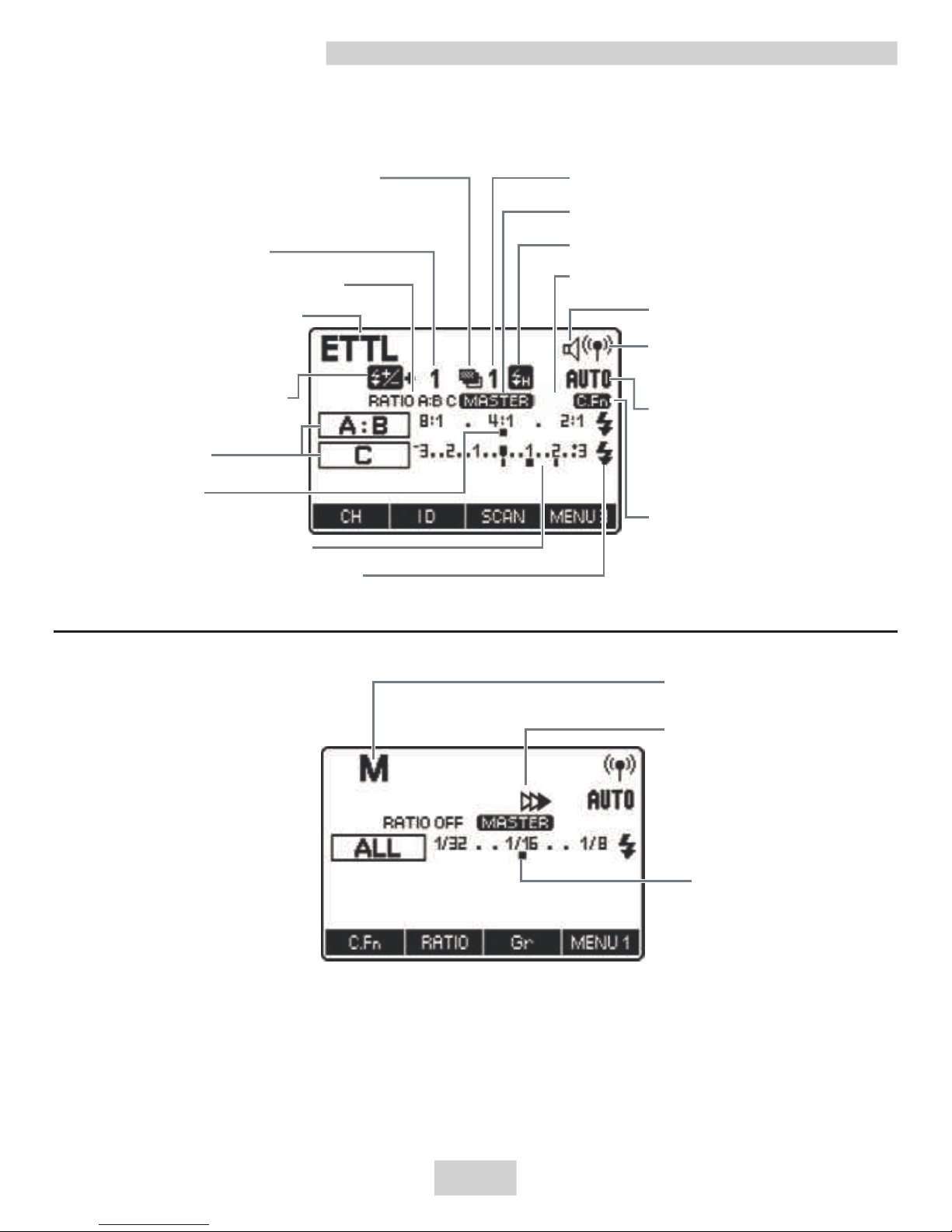
Manual flash
M:Manual Flash
Manual flash
output
E-TTL(II) Autoflash
FEB
FEC amount
ETTL:E-TTL II/E-TTL
autoflash
Flash exposure
compensation(FEC)
Firing group
Flash ratio
Flash exposure level
Slave flash ready
Custom
Functions
Ch:Channel
AUTO: Channel
automatic setting
Radio transmission
wireless shooting
Beep
Personal Functions
High-speed sync
Master
FEB sequence
RATIO:Flash ratio
The display will show only the settings currently applied.
The functions displayed above function buttons 1 to 4,
change according to the setting’s status.
When a button or dial is operated, the LCD panel illuminates.
Manual Flash 2nd
curtain sync
3
Nomenclature
Page 7
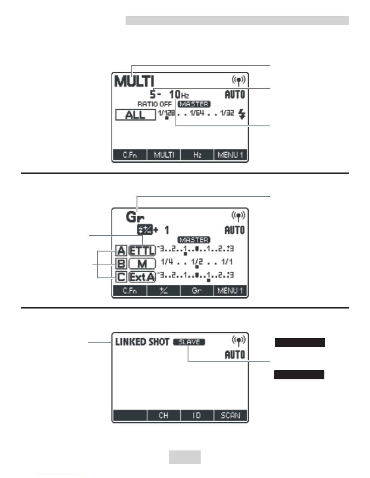
Multi(stroboscopic) flash
Group firing
Linked shooting
MULTI:
Multi flash
Number of flashes
Flash frequency
Gr : Group flash
Flash mode
Firing group
LINKED SHOT:
Linked shooting
SLAVE
MASTER
SLAVE
MASTER
4
Nomenclature
Page 8
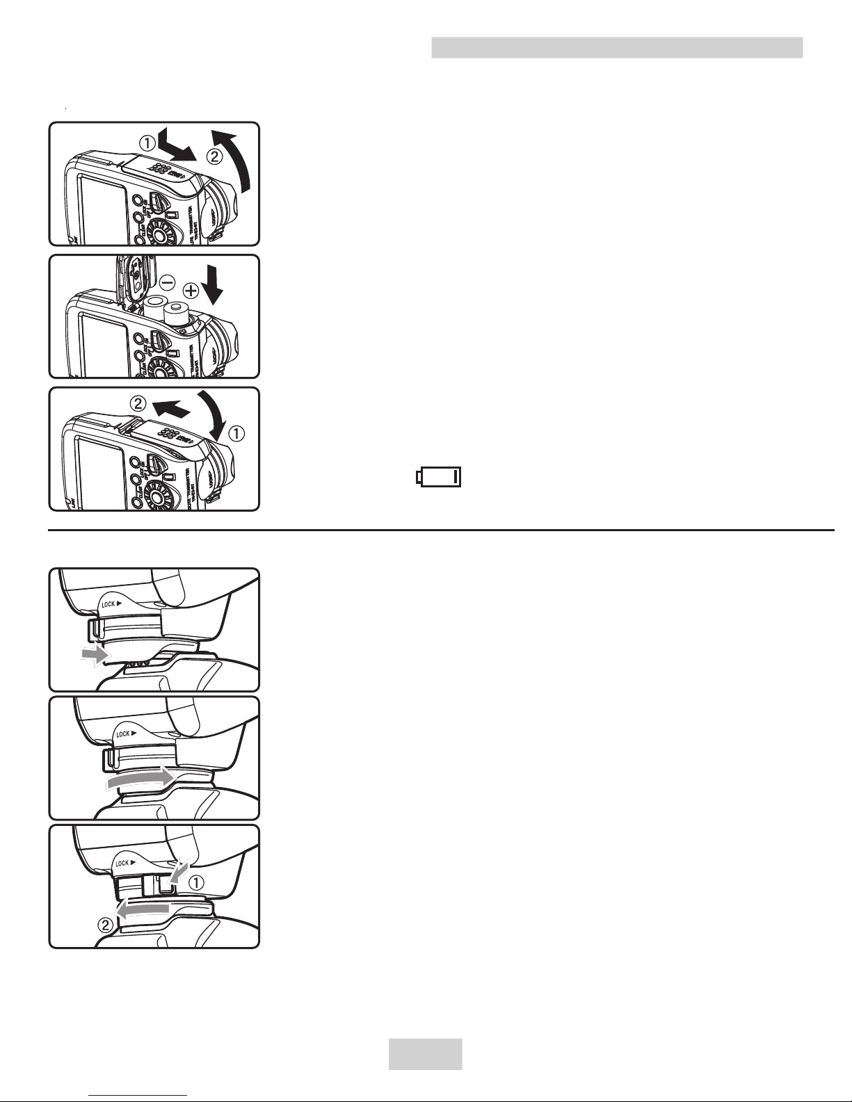
1.Install two AA/LR6 batteries.
1.Open the cover:Slide the cover down as
shown and open the battery compartment
cover.
2.Install two AA batteries: Install two AA
batteries according to the + and - marks,
rechargeable batteries of 1.2V can be used.
3.Close the battery: Close the battery
Compartment cover and slide it up.
Remove the batteries when the product
is not used for long time. Please replace
the both two batteries at the same time.
When < > is displayed, replace the
batteries with new ones.
Preparation Before Use
5
2.Attaching and Detaching the Transmitter
1.Attach the transmitter.
Slip the transmitter’s mounting foot all the
way into the camera’s hot shoe.
2.Secure the transmitter.
On the mounting foot, slide the lock lever to
the right. When the lock lever clicks in place,
it will be locked.
3.Detach the transmitter.
While pressing the lock-release button, slide
the lock lever to the left and detach the
transmitter.
Before attaching or detaching the transmitter, be sure to
turn the transmitter power off.
Page 9
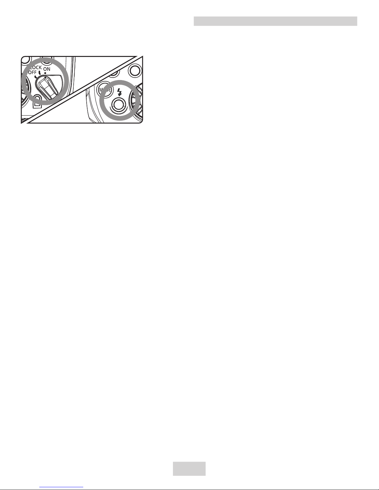
ØThe LCD panel illuminates.
The charge lamp lights when the
wireless shooting (slave) is ready.
During wireless shooting, press the
transmitter’s charge lamp (test flash
button) to fire a test flash.
About Auto Power Off
To save battery power, the power will turn off automatically
after 5 min. of idle use. To turn on the transmitter again, press
the camera’ s shutter button halfway, or press the test flash
button (charge lamp).
About the Lock Function
By setting the power switch to <LOCK>, you can disable flash’ s
button and dial operations. Use this to prevent the transmitter
function settings from being accidentally changed after you set
them.
If you operate a button or dial, <LOCKED> is displayed on the
LCD panel .
About the LCD Panel Illumination
When a button or dial is operated, the LCD panel illuminates in
greenfor 12 sec. When setting a function, the illumination
continues until the setting is complete.
The transmitter settings are stored even when the
power is turned off.
You can fire a test flash even when the power switch is
set to the <LOCK> position. Also, when a button or dial is
operated, the LCD panel illuminates.
3.Turning on the Power:Set the power switch to <ON>.
Preparation Before Use
6
Page 10
C
A
B
MASTER
SLAVE
SLAVE
SLAVE
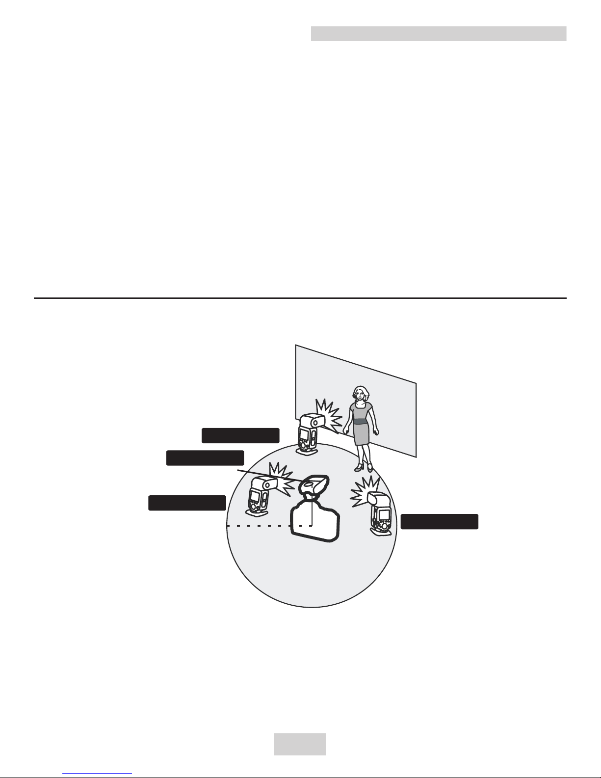
Positioning and Operation Range
(Example of wireless flash shooting)
Transmission distance
Approx. 100 m
Using a transmitter and a Speedlite compatible with radio
transmission wireless shooting makes it easy to shoot with
advanced wireless multiple flash lighting, in the same way as
normal E-TTL II/E-TTL autoflash shooting.
The system is designed so that the settings of the transmitter
attached to the camera (master) are automatically reflected on
the Speedlite that is wirelessly controlled (slave). Therefore, you
do not need to operate the slave unit while shooting.
The basic relative positions and operating range are as shown in
the figure. You can then perform wireless E-TTL II/E-TTL
autoflash shooting just by setting the master unit to <ETTL>.
Wireless Flash Shooting
Before shooting, perform a test flash (p.10) and test
shooting.
The transmission distance may be shorter depending
on the conditions such as the positioning of slave units,
the surrounding environment and weather conditions.
7
Page 11
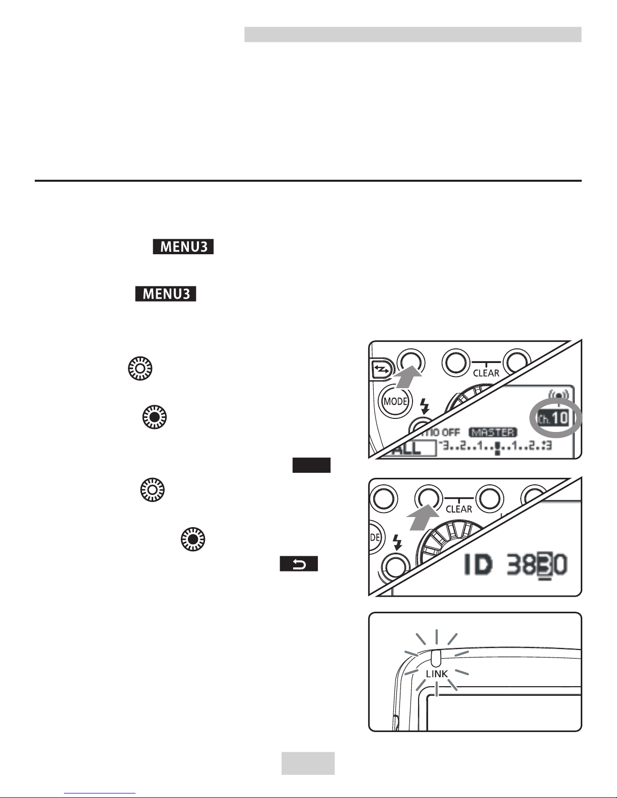
Wireless Settings
1.Display < >.
Press func tio n button 4 t o
displaym < >.
2.Set a channel.
Press function button 1 <CH>.
Turn < > to select “AUTO”
or a channel from Ch. 1 to 15, and
press the < > button.
3.Set a wireless radio ID.
Press function button 2 < >.
Tu r n < > t o s e l e c t t h e
position(digit) or number to set,
and press the < > button.
Press function button 4 < > to
return to the shooting-ready state.
ØWhen transmission between the
master unit and slave unit is
established, the <LINK> lamp is lit
in green.(Refer to page 26)
To avoid interference, Set the same channel and ID
for both the master unit and slave unit.
Set a flash that is compatible with radio transmission
wireless flash shooting as the slave unit. For the slave
unit settings, see the flash’s instruction manual.
ID
8
Setting the Master Unit Transmission Channel /
Wireless Radio ID.
Page 12
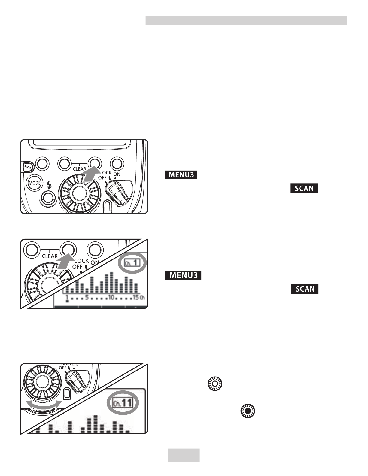
Scanning while “AUTO” is set
Scanning while Ch. 1 to 15 is set
Scanning the Master Unit Transmission Channels to Set
You can scan the radio reception status and set the master unit’s
transmission channel automatically or manually. When the
channel is set to “AUTO”, the channel with the best reception
signal is automatically set. When setting the channel manually,
you can set the transmission channel again while referring to the
scan results.
Wireless Settings
Run the scan.
Press function button 4 to display
< >.
Press function button 3 < >.
ØThe channel is reset to one with a
good reception signal.
2.Set a channel.
Turn< >to select a channel
from Ch1 to 15.
Press the < > button to set
the channel and return to the
shooting ready state.
1.Run the scan.
Press function button 4 to display
< >.
Press function button 3 < >.
T h e r a di o r e c e p t i on s t at u s i s
displayed in a graph.
The higher the peak of the channel in
the graph, the better the radio reception
signal.
9
Page 13
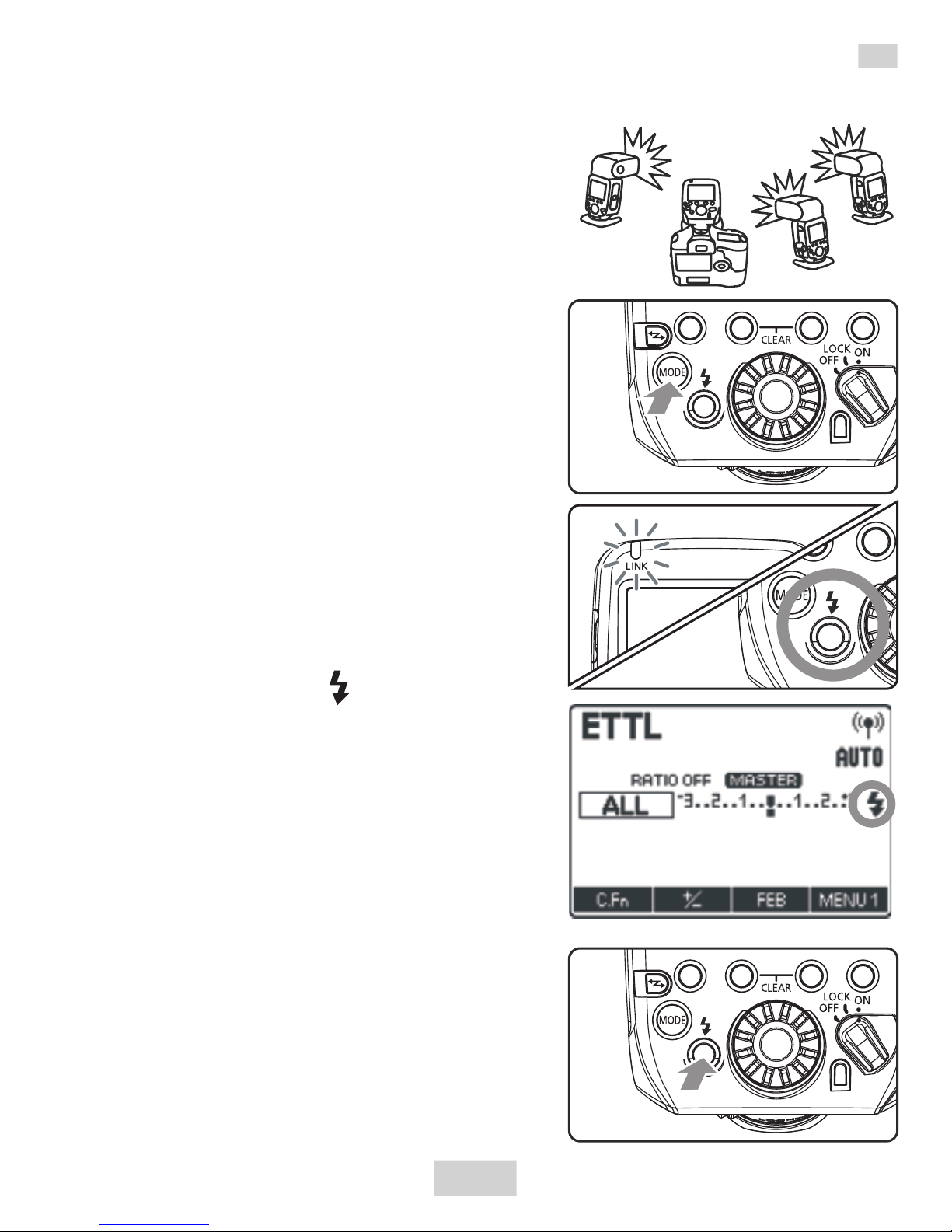
ETTL:Fully Automatic Wireless Flash Shooting
1.Set the flash as the slave unit A,
B or C . The flash will not fire if
it is set to D or E.
2.Set the same channel and ID of
the master unit and slave unit
.(p.8)
3.Position the camera and the
flash.(p.7)
4.Press the <MODE> button on
the master unit and set the
flash mode to <ETTL>.
The slave unit is set automatically
to <ETTL> during shooting via the
control from the master unit.
5.Check the transmission status
and that the flash is ready.
Check that the <LINK> lamp is lit
in green.
Check that the < > slave flash-
ready icon is lit on the master unit’s
LCD panel.
When the recycling of all the flash
units is completed, the master unit's
charge lamp lights.
6.Check the operation.
Press the master unit’s test flash
button (charge lamp). The slave unit
flashes.
7.Take the picture.
If a standard flash exposure was
o b t a i n e d , t h e f l a s h e x p o s u r e
confirmation lamp lights for 3 sec.
10
Page 14
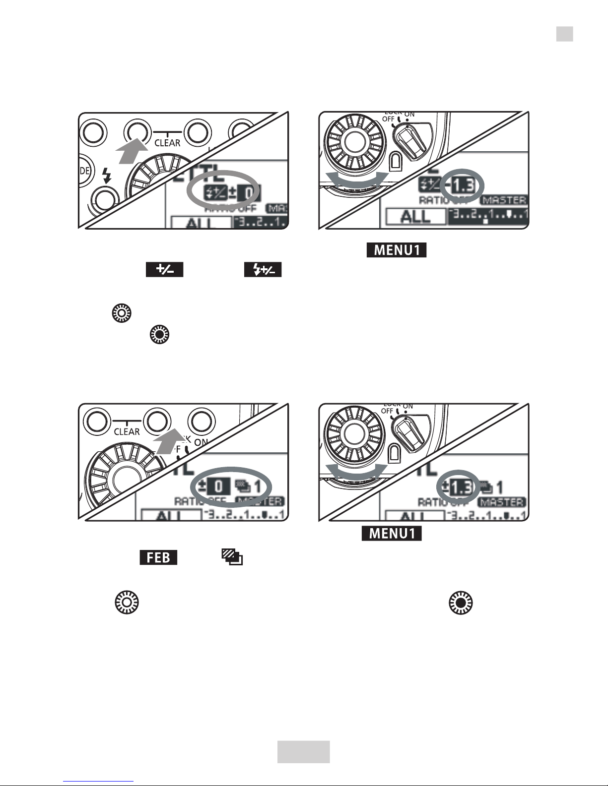
FEC (Flash Exposure Compensation)
FEB (Flash Exposure Bracketing)
1.Press function button 4 to display < >.Press function
button 2 < >. < > is displayed and the FEC amount
is highlighted.
2.Turn < > to set the flash exposure compensation amount,
and press < >. The FEC amount is set.
To cancel FEC, return the amount to “±0”.
Support 1/3-stop increments to set FEC/FEB within ±3.
1.Press function button 4 to display < >. Press function
button 3 < >. < > is displayed and the FEB level display
is highlighted.
2.Turn < > to set the FEB level, and press < >. The FEB
level is set.
W h e n u s e d t o g e t h e r w i t h f l a s h e x p o s u r e
compensation, FEB shooting is performed based on the
flash exposure compensation amount.
ETTL:Fully Automatic Wireless Flash Shooting
11
Page 15
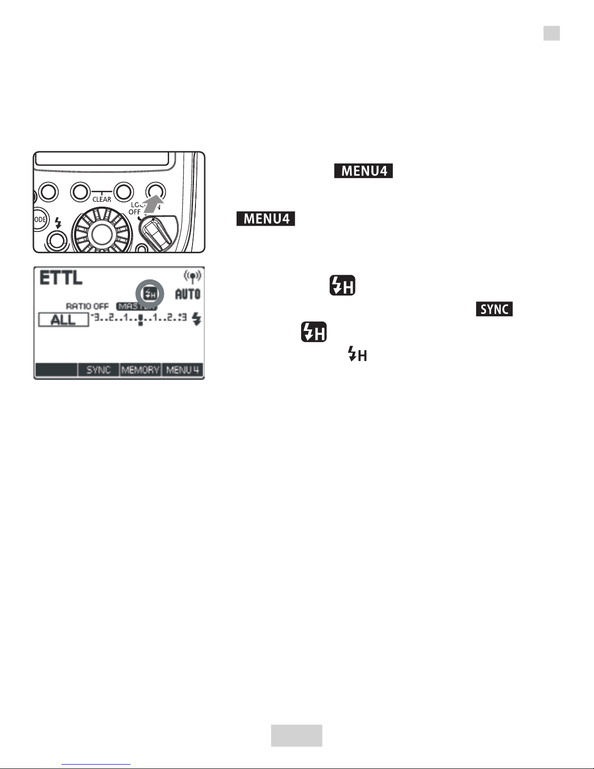
High-speed Sync
With the high-speed sync function, the flash can synchronize
with all shutter speeds. This is convenient when you want to
use aperture-priority AE for fill-flash portraits of a subject.
1.Display < >.
Press function button 4 to display
< >.
2.Display < >.
Press function button 2 < > to
display < >.
Check that < > is lit in the viewfinder.
FEL:FE Lock
FE (Flash Exposure) lock locks the correct flash exposure setting
for any part of the scene.
Perform FE lock by operating the camera. For the operations,
see the camera and flash’s instruction manual.
About Master Units
You can use two or more master units (master units + slave
units =maximum of 16 units). By preparing multiple cameras
with master units attached, you can shoot by changing cameras
while keeping the same lighting (slave units).
Note that when using two or more master units, the color of the
<LINK> lamp varies depending on the order in which the power
was turned on. The first master (main master) is green and the
second and subsequent masters (sub-masters) are orange.
12
ETTL:Fully Automatic Wireless Flash Shooting
Page 16
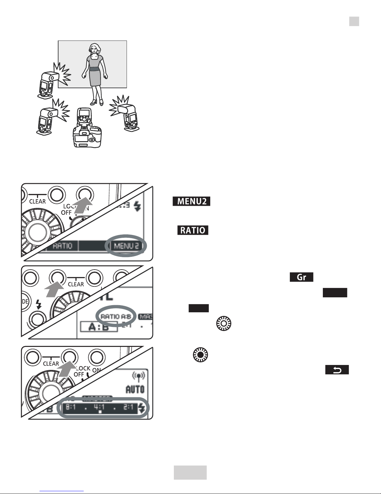
C
A
B
T h e e x p o s u r e i s c o n t r o l l e d
automatically so that the total
fl as h o utput of firing gr ou ps
results in the standard exposure.
1.Set the firing group of the
slave units.
Operate and set the slave units
one by one.
2 . P r e s s t h e m a s t e r u n i t ’ s
function button 4 to display
< >.
3.Press function button 2
< > and set to <A:B> or
A:BC>.
4.Set the flash ratio.P re ss
function button 3 < >.
Press function button 3 < >
or < >.
Turn < > to set the flash ratio
or the flash exposure, and press
the < > button.
Press function button 4 < >
to return to the shooting-ready
state.
5.Take the picture.
The slave units flash at the set
flash ratio.
ETTL: Wireless Multiple Flash Shooting with Flash Ratio
A:B
/
+
-
/
+
-
C
13
Page 17
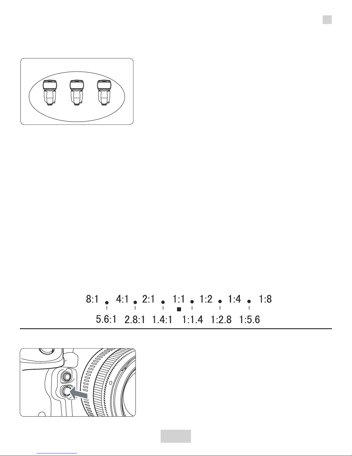
Slave Group Control
Firing group A
If you need more flash output or wish
to perform more sophisticated lighting,
you can increase the number of slave
units.
Simply set an additional slave unit to
the firing group (A, B or C) whose flash
output you want to increase. You can
increase the number of slave units up
to 15 units in total.
For example, if you set a firing group with three slave units to
<A>,the three units are controlled as a single firing group A with
a large flash output.
To fire the three firing groups A, B and C at the same time, set
<A:B:C>. With the < A:B > setting, firing group C does not fire.
If you shoot with firing group C pointing directly toward the
main subject, overexposure may result.
The flash ratio of 8:1 to 1:1 to 1:8 is equivalent to 3:1 to 1:1 to
1:3 (1/2-stop increments) when converted to number of stops.
The details of the flash ratio settings are as follows.
14
Modeling Flash
Modeling Flash from a Master Unit
Press the depth-of-field preview
button on the camera.
The flash fires continuously for 1
sec.
ETTL: Wireless Multiple Flash Shooting with Flash Ratio
Page 18
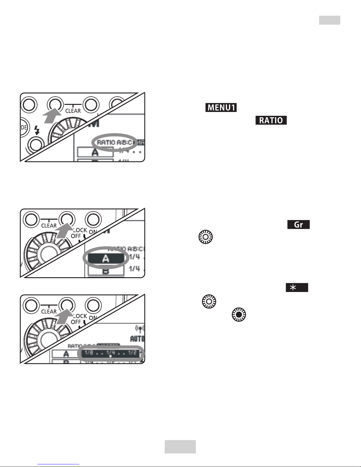
M: Wireless Multiple Flash Shooting with Manual Flash Output
1.Set the flash mode to <M>.
2.Set the number of firing groups.
While < > is displayed, press
function button 2 < > and set
the groups to fire.
The setting changes as follows
each time you press the button:
ALL(RATIO OFF)→
A/B(RATIO A:B)→
A/B/C(RATIO A:B:C)
3.Select a firing group.
Press function button 3< >,
turn < > and select the group for
which you want to set the flash
output.
4.Set the flash output.
Press function button3< >.
Turn < > to set the flash output,
and press the < > button.
Repeat steps 3 and 4 to set the
flash output of all groups.
5.Take the picture.
Each group fires at the set flash
output.
This describes wireless (multiple flash) shooting using manual
flash.You can shoot with a different flash output setting for each
slave unit(firing group). Set all parameters on the master unit.
/
+
-
15
When ALL <RATIO OFF> is set, set A, B or C as the firing group
for the slave units. The flash will not fire if it is set to D or E.
To fire multiple slave units with the same flash output, select
ALL <RATIO OFF> in step 2.
Page 19
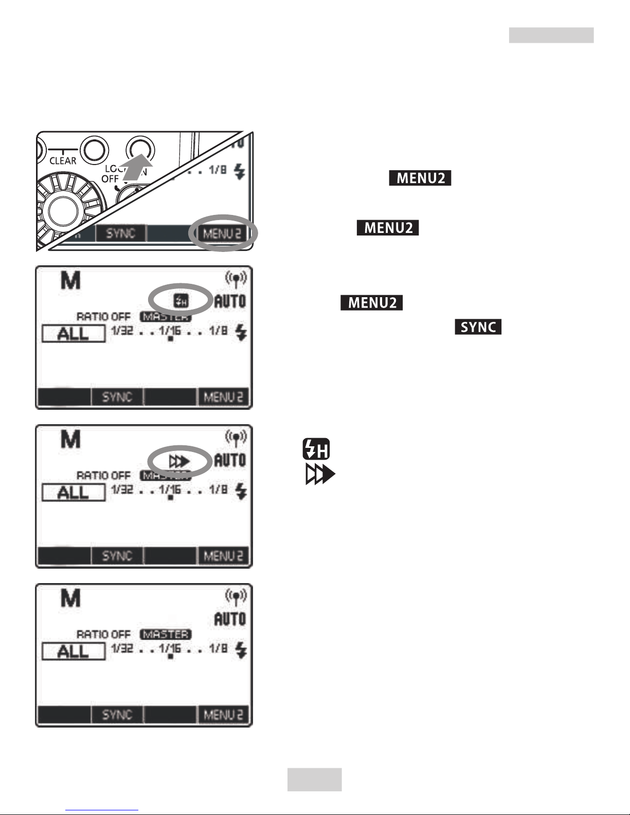
M:The shutter sync of manual flash setting
1.Display < >.
Press fun ction b utton 4 to
display< >.
2.Shutter Sync setting
While < > is displayed, press
function button 2 < > and set
the shutter sync.
The setting changes as follows
each time you press the button:
:High-speed Sync
:2nd Curtain Sync
(no icon):1st Curtain Sync
You can use 1st curtain Sync, high-speed Sync, or 2nd
curtain sync in manual flash.
16
The 2nd curtain sync can be
used in manual flash only.
When using the 2nd curtain
sync , wireless settings and
other parameters recommend
using the speedlite transmitter
settings.
Page 20
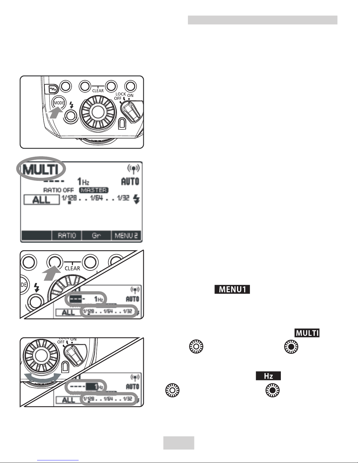
MULTI: Stroboscopic Flash
In stroboscopic flash, set the flash output, number of
flashes, and flash frequency (number of flashes per second
= Hz).
1 . S e t t h e f l a s h m o d e t o
<MULTI>.
Press the <MODE> button on
the
master unit and set to <MULTI>.
2.Set the firing groups and the
flash output.
Set the number of firing groups
and the flash output for each
group by referring to the manual
flash on the preceding page.
3.Set the flash frequency and
thenumber of flashes.
While < > is displayed,
perform the following procedure.
To set the number of flashes,
press function button 2 < >,
turn < > and select < >.
To set the flash frequency, press
function button 3 < >, turn
< > and select < >.
17
Page 21
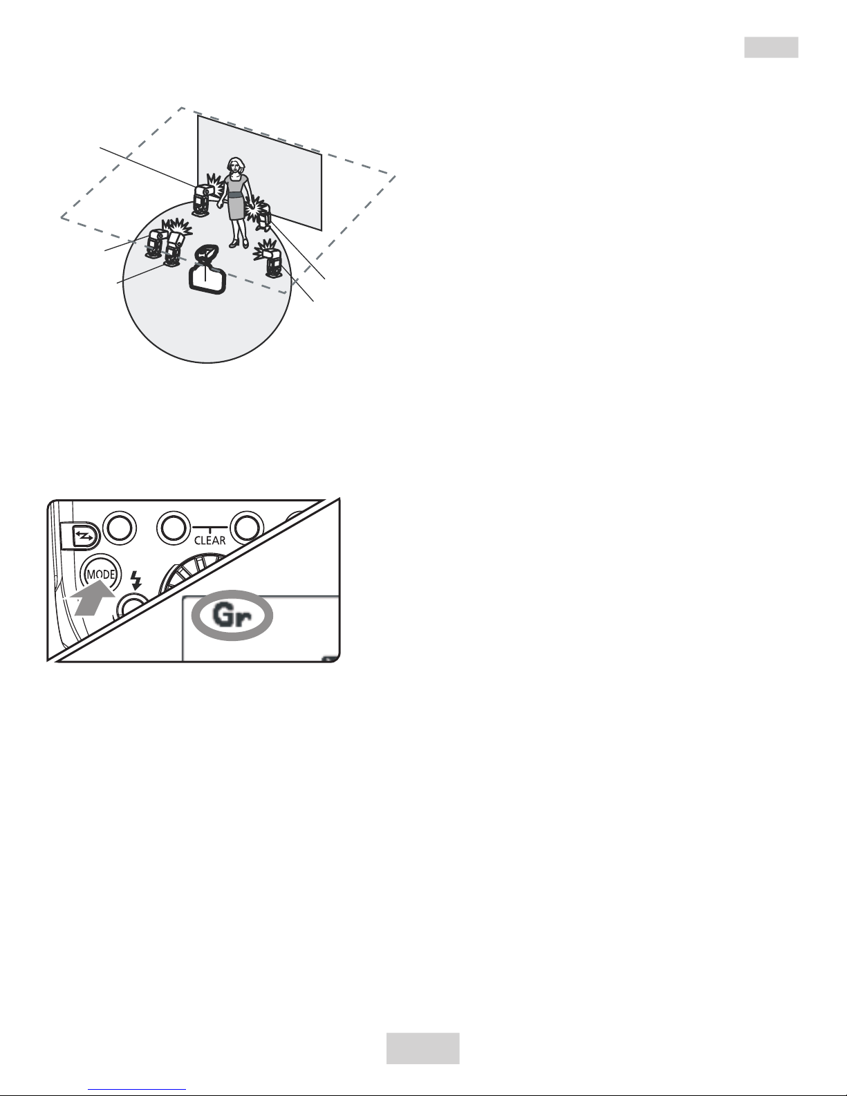
Gr: Shooting with a Different Flash Mode for Each Group
A
B
C
E
D
Ext.A
E-TTL II
Y o u c a n s h o o t w i t h a
different flash mode set for
each firing group, with up to
5groups (A/B/C/D/E).
The flash modes that can be
s e t a r e E - T T L I I / E - T T L
autoflash, Manual flash and
Auto external flash metering.
This function is for advanced
u s e r s w h o a r e v e r y
knowledgeable and experienced
in lighting.
When using the <Gr> flash mode of the camera
released from 2007 to 2011, all the parameters
should be set up through the speedlite transmitter.
1.Set the flash mode to <Gr>.
Press the <mode> button on
the master unit and set the flash
mode to<Gr>.
2.Set the firing group on the
slave units.
Operate and set the slave
units one by one.
Set a firing group (A/B/C/D/E)
for all the slave units.
18
* The flash mode settings
are indicated only as an
example.
Manual
Flash
Manual
Flash
Manual
Flash
Page 22
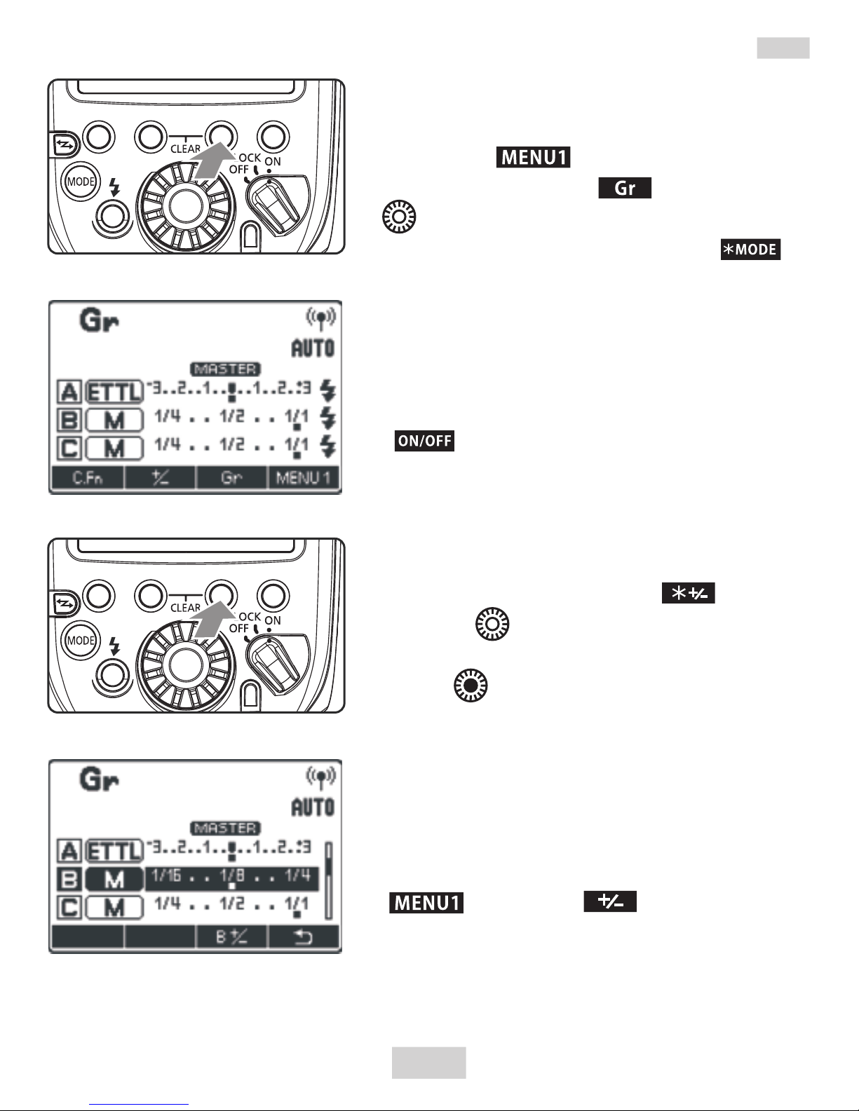
3.Set the flash mode of each firing
group by operating the master unit.
While < > is displayed, press
function button 3 < > and turn
< > to select the group.
Press function button 2 < >
and select the flash mode of the
selected group from < E-TTL>、< M
> and <Ext.A >.
To turn the firing of the selected
group off, press function button 1
< > to set it to <OFF>.
4.Set the flash output or flash
exposure compensation amount.
While a firing group is selected,
press function button 3 < >.
Turn < > to set the flash function
corresponding to the flash mode, and
press < >.
When using the <M> mode, set
the flash output. When using the < ETTL> or <Ext.A> mode, set the flash
exposure compensation amount as
required.
If you press function button 2
< > when < > is displayed,
flash exposure compensation can be
set for all the firing groups.
Gr: Shooting with a Different Flash Mode for Each Group
19
Page 23

You can perform remote release (remote
control shooting) from a flash set as a
slave unit. (see the flash’s instruction
manual).
*When using the function with the cameras released until
2011, it needs the shutter release cable LS-MINIB/C3 or
LS-MINIB/C1(sold separately). As for the EOS digital
cameras(such as EOS-1D X) released after 2012, it does
not need the shutter release cable.
Remote Release from a Slave Unit/Linked Shooting
Remote Release from a Slave Unit*
20
Linked shooting*
Linked shooting is a function that automatically releases the
shutter of a slave unit camera by linking it to a master unit
camera. You can shoot with linked shooting for up to 16
units, including both master units and slave units. This is
convenient when you want to shoot a subject from multiple
angles at the same time.
To shoot with linked shooting, attach a flash that supports
radio transmission wireless shooting or the Speedlite
Transmitter YN-E3-RT to the camera.
Slave unit camera
Transmission
distance
Approx. 100 m
Slave unit camera
Slave unit camera
Slave unit camera
Ma st er u ni t
ca me ra
Page 24

1.Set to linked shooting mode.
Press the < > button continuously until <LINKSHOT> is
displayed on the LCD panel. Linked shooting mode’ s “Slave
unit”is set.
Press the < > button again to set“Master unit” of the
linked shooting mode.
2.Set the channel and ID.
3.Set the camera’s shooting functions.
4.Set all the transmitters or flash.
Repeat steps 1 to 3 and set all the transmitters or flashes to
“Master unit” or “Slave unit” in the linked shooting mode.
When pressing the < > button to change the setting of a
unit from ”Slave unit” to ”Master unit,” the other transmitters (or
Sp eed lit es) th at were se t t o ”Master un it” u ntil t hen
automatically switch to “Slave unit”.
5.Set up the slave unit cameras.
Check that the <LINK> lamp of the slave unit is lit in green.
6.Take the picture.
Check that the <LINK> lamp of the master unit is lit in green
and take the picture.
The slave unit cameras are released in coordination with the
master unit camera.
After shooting with linked shooting, the <LINK> lamp of the
slave unit is briefly lit in orange.
Linked Shooting
21
Page 25

Transmitter Control from Camera’s Menu Screen
When using EOS digital cameras released since 2007, you can
set flash functions, transmitter functions or Custom Functions
from the camera’s menu screen. See the camera’s instruction
manual.
1.S ele ct [ E xt ern al Spe ed l it e
control].
Select [External Speedlite control]
or [Flash control].
2.Select [Flash function settings].
Select [Flash function settings] or
[External flash func. setting].
T h e s c r e e n c h a n g e s t o t h e
(external) flash function settings
screen.
3.Set the function.
T h e s e t t i n g s c r e e n v a r i e s
depending on the camera.
S e lec t a n i t em a n d s e t t he
Settings Available in [Flash function settings]
EOS digital cameras released since 2012
When using the transmitter with cameras such as EOS-1D X,
you can set the functions for “Radio transmission wireless
shooting” in the [Flash function settings] screen.
EOS digital cameras released from 2007 to 2011
When performing “ Radio transmission wireless shooting” ,
set the functions by operating the transmitter.
22
Page 26

E-TTL II flash metering
For normal exposures, set it to [Evaluative]. If [Average] is set,
the flash exposure will be averaged for the entire scene
metered by the camera. Flash exposure compensation may be
necessary depending on the scene. This setting is for
advanced users.
Flash synchronization speed in Av mode
You can set the flash sync speed when performing wireless
flash shooting in aperture-priority AE (AV) mode.
Flash mode
You can select the flash mode from [E-TTL II], [Manual flash],
[MULTI flash] and [Individual group control] to suit your
desired flash shooting.
Shutter synchronization
You can select the flash firing timing/method from [1st
curtain] and [High-speed synchronization]. To perform
normal wireless flash shooting, set it to [1st curtain].
Flash exposure compensation
In the same way as normal exposure compensation, you can
set exposure compensation for flash. The flash exposure
compensation amount can be set up to ±3 stops in 1/3-stop
increments.
FEB
You can take three shots while automatically changing the
flashoutput. The settable range is up to ± 3 stops in 1/3-stop
increments.
Wireless flash functions (setting)
R a dio tr a n s m i ssio n w i r e less f l a s h s h ooti n g i s s e t
automatically.
Clear Speedlite (function) settings
You can return the transmitter settings to their default
settings.
23
Transmitter Control from Camera’s Menu Screen
Page 27

Transmitter Custom Function Settings
The displayed contents var y depending on the camera.
If C.Fn-20 and 22 are not displayed, set them by
operating the transmitter. For the Custom Functions,
see pages 26 to 27.
1.Select [Flash C.Fn settings].
Select [Flash C.Fn settings] or [External flash C.Fn setting].
You can now set the Custom Functions of the transmitter.
2.Set the Custom Function.
Select the Custom Function number and set the function.
To clear all the Custom Function settings, select [Clear all
Speedlite C.Fn’s] or [Clear ext. flash C.Fn set.] in step 1.
24
Page 28

You can customize the transmitter features to suit your shooting
preferences with Custom Functions and Personal Functions.
1.Dis p lay the Custo m Functions
screen.
Press function button 1< >
T h e C u s t om F u n ct i o n s s c r e e n i s
displayed.
2.Select an item to set.
Turn < > to select an item(number)
to set.
3.Change the setting.
Press the < > button, The setting
is displayed. Turn < > to select the
setting that you want, and press the
< > button.
Press function button 4 < > to
return to the shooting-ready state.
Custom Function List
C.Fn
C.Fn: Setting Custom Functions
25
Number Icon Custom Functions Page
C.Fn-01 Auto power off
C.Fn-02 Modeling flash
C.Fn-03 FEB auto cancel
C.Fn-04 FEB sequence
C.Fn-07 Test firing with autoflash
C.Fn-08 AF Assist Beam Emitter
C.Fn-13 Flash exposure metering setting
C.Fn-20 Beep
C.Fn-22 LCD panel illumination
P.26
P.27
Page 29

0: (Enabled (Depth-of-field preview button))
Press the camera’s depth-of-field preview button to fire the
modeling flash.
1: (Enabled (Test firing button))
Press the transmitter’s test flash button to fire the modeling flash.
2: / (Enabled (with both buttons))
Press the camera’s depth-of-field preview button or the
transmitter’s test flash button to fire the modeling flash.
3: OFF (Disabled)
Disables the modeling flash.
When the transmitter is not operated for 5 min., the power turns
off automatically to save energy. You can disable this function.
0: ON (Enabled)
1: OFF (Disabled)
You can set whether or not to cancel FEB automatically after
shooting three shots with FEB.
0: ON (Enabled)
1: OFF (Disabled)
You can change the order of the FEB sequence, 0: Standard
exposure, – :Decreased exposure (darker) and +: Increased
exposure (brighter).
0: 0 → → +
1: - → 0 → +
-
(Auto power off)
C.Fn-01:
C.Fn-02:
(Modeling flash)
C.Fn-03:
(FEB auto cancel)
(FEB sequence)
C.Fn-04:
C.Fn: Setting Custom Functions
26
Page 30

You can change the flash output when firing the test flash in
E-TTL II/E-TTL autoflash mode.
0: 1/32 (1/32)
1: 1/1 (Full output)
C.Fn-07:
(Test firing with autoflash)
C.Fn-08: (AF-assist beam firing)
0: ON (Enabled)
1: OFF(Disabled)The AF-assist beam is not fired from
the speedlite transmitter
C.Fn-13: (Flash exposure metering setting)
0: + (Speedlite button and dial)
1: (Speedlite dial only)
You can perform flash exposure compensation by directly
turning < >, without pressing the < > button.
C.Fn-20: (Beep)
You can enable a beep to sound when the slave units are
fully charged.
0: OFF (Disabled)
1: ON (Enabled)
C.Fn-22: (LCD panel illumination)
When a button or dial is operated, the LCD panel illuminates.
You can change this illumination setting.
0: 12sec (On for 12 sec.)
1: OFF (Disable panel illumination)
2: ON (Illumination always on)
C.Fn: Setting Custom Functions
27
Page 31

Reference
28
About the <LINK> Lamp
The color of the <LINK> lamp changes depending on the
transmission status of the master unit and the slave unit.
If the transmission channels of the master unit and
slave unit are
different, the slave unit does not fire. Set both to the
same number, or set both to ”AUTO”.
Color
Status Description Action
Green Lit
Transmission
OK
–
Lit Not connected Check the channel and ID
Too many units
Master units + slave units =
16 units or less
Error Turn the power off and on again
Blinking
Red
Clearing Transmitter Settings
Press function buttons 2 and 3
simultaneously for 2 seconds or
longer. The transmitter settings
are cleared and the shooting mode
returns to <ETTL> flash mode.
Page 32

It needs using single autofocus for the lens.
Enable or disable the AF assist Beam Emitter
function through the camera menu custom function
(P.24) or speedlite transmitter custom function (P.
25)(C.Fn8).
AF Assist Beam Emitter
When using AF under low-light,
the built-in AF-assist beam emitter
of the speedlite transmitter will
be emitted automatically to make
it easier to autofocus.
29
Reference
Firmware Update
1.Log in the YONGNUO official website (www.hkyongnuo.com)
to download the firmware update software and the latest
firmware.
2.Power off, use USB-MINIB cable connect to PC.
3.Press the <MODE> button and set the power switch to <ON>,
the screen will enter into firmware upgrade interface.
4.Complete the firmware upgrade operation according to the
prompt of software.
Page 33

Troubleshooting Guide
Power does not turn on.
Make sure that the batteries are installed in the correct
orientation.
Insert the mounting foot into the camera’s hot shoe all the
way, slide the lock lever to the right, and secure the transmitter
to the camera .
If the electrical contacts of the transmitter and camera are
dirty, clean the contacts.
The charge lamp lights when the wireless shooting (slave) is
ready.
The power turns off by itself.
The transmitter’ s auto power off function has activated.
Press the shutter button halfway, or press the test flash button .
The slave unit does not fire.
Check that the slave unit supports radio transmission wireless
flash shooting.
Set the slave unit to < > < >.
Set the transmission channels and wireless radio IDs of the
master unit and slave unit to the same numbers.
Check that the slave unit is within the transmission range of
the master unit.
Unable to use the AF assist beam emitter.
Check the custom function C.Fn08.
Firmware update failed or the screen display the
firmware upgrade interface all along.
Disconnect, restart the equipment and try again.
The screen displays "ERROR: 2001"
Try upgrade the firmware again.
30
Page 34

The picture is underexposed or overexposed.
If there was a highly reflective object (glass window, etc.) in
the picture, use FE lock).
If the subject looks very dark or very bright, set flash
exposure compensation.
When high-speed sync is set, the effective flash range is
shorter.
Position the slave unit closer to the subject.
When using autoflash shooting with three firing groups A, B
and C, do not fire with firing group C pointed toward the main
subject.
When shooting with a different flash mode setting for each
firing group, do not fire with multiple firing groups set to
<ETTL> or <Ext.A> pointed toward the main subject .
The picture is very blurred.
When the shooting mode is set to <AV> and the scene is
dark, slow sync is enabled automatically (the shutter speed
becomes slower). Use a tripod, or set the shooting mode to <P>
or fully automatic mode. Note that you can also set the sync
speed in [Flash sync. speed in Av mode]
Cannot release from a slave unit.
When an EOS camera which was released up to 2011, has
remote control terminal and is compatible with E-TTL II/E-TTL
autoflash is used to perform remote release from a slave unit or
when it has been set as the slave unit during linked shooting, the
shutter release cable “ LS-MINIB/C3 “ or “ LS-MINIB/C1 ”
(sold separately) is necessary.
31
Troubleshooting Guide
Page 35

Type: On-camera Speedlite transmitter
Compatible cameras: EOS type-A camera compatible with
E-TTL II/E-TTL autoflash
Exposure control
system: E-TTL II/E-TTL autoflash, manual
f la s h , s t ro b os c o pi c f la s h, a ut o
external flash metering*
*Only when the flash mode is set to
<Gr>
Frequency: 2405 - 2475 MHZ
Modulation system: P r i m a r y m o d u l a t i o n : O Q P S K ,
secondary modulation: DS-SS
Channel: Auto, Ch. 1 - 15
Wireless radio ID: 0000 - 9999
Slave unit control: Up to 5 groups (A/B/C/D/E), up to 15
units
Transmission distance: Approx. 100 m
Flash ratio control: 1:8 - 1:1 - 8:1, 1/2-stop increments
Flash exposure
compensation: ±3 stops in 1/3- increments
FEB: ±3 stops in 1/3- increments (when
u s e d w i t h f l a s h e x p o s u r e
compensation)
FE lock: Press the camera’s <M-Fn>, <FEL>
or <*> button
High-speed sync: Provided
Manual flash: 1 / 1 - 1 / 1 2 8 p o w e r ( 1 / 3 - s t o p
increments)
Stroboscopic flash: Provided (1 - 500 Hz)
32
Specifications
Page 36

33
Specifications
Slave flash battery check: On the master unit’s LCD panel,
the < > icon lights, the slave
unit’s AF-assist beam emitter
bl ink s and t he charg e l amp
lights.
Flash exposure confirmation: F la sh expos ur e c on fi rm at ion
lamp lights
Modeling flash: Fired with camera‘s depth-of-
field preview button
Linked shooting: Provided
Custom Functions: 9
AF assist Beam Emitter: Provided
Firmware update : Provided
Power source: 2 AA/LR6 alkaline batteries Ni-
MH batteries
Wireless flash shooting Approx. time:1 0 c o n t i n u o u s
hours*
time *When using AA/LR6 alkaline
batteries
Power saving: Power off after 5 min. of idle
operation
Dimensions: Approx. 67.7 (W) x 66.7 (H) x
81.3 (D) mm
Weight: Approx. 110 g (transmitter only,
excluding batteries)
The functions of this user manual are based on test conditions
of our company.Further notice will not be given if the design
and specifications change.
The YONGNUO logo in this manual includes the registered
trademark or trademark of Shenzhen Yongnuo Photography
E q u i p m e n t C o . , L t d i n C h i n a o r / a n d o t h e r
countries(regions).All other trademarks are the property of
their respective owners.
Page 37

目录
前言 . . . . . . . . . . . . . . . . . . . . 1
部件名称 . . . . . . . . . . . . . . . . . 2-4
使用前准备 . . . . . . . . . . . . . . . . 5-6
无线闪光拍摄 . . . . . . . . . . . . . . . . 7
无线设置 . . . . . . . . . . . . . . . . . 8-9
ETTL:使用全自动无线闪光拍摄 . . . . . . . . . 10-14
M:使用手动闪光输出的无线多重闪光拍摄. . . . 15-16
Multi:频闪闪光 . . . . . . . . . . . . . . . 17
Gr:为各组设定不同的闪光模式拍摄 . . . . . . 18-19
从从属单元进行遥控释放/联动拍摄 . . . . . . 20-21
从相机的菜单画面进行信号发射器控制 . . . . . 22-23
C.Fn:信号发射器自定义功能设置 . . . . . . . 24-27
参考 . . . . . . . . . . . . . . . . . . 28-29
故障排除 . . . . . . . . . . . . . . . . 30-31
规格 . . . . . . . . . . . . . . . . . . 32-33
阅读本使用说明书的同时还请参阅相机和闪光灯的使用说
明书。
开始使用本信号发射器之前,阅读本使用说明书以及相机
和闪光灯的使用说明书以熟悉操作。
Page 38

前言
首先感谢您选购永诺产品。
永诺闪光灯信号发射器YN-E3-RT是无线闪光拍摄用信号发射
器。最多可以控制5组(15个单元)具有使用无线电传输进行
无线多重 闪光拍摄 功能的闪 光灯。信 号 发射器 还 具有等同 于
EOS-1D系列相机的防尘和防水滴性能。
双 向2.4G无线电通讯,全面兼容原厂ST-E3-RT/600EX-
RT无线信号
15个物理频道,1个自动频道,多达10000个可设置的摄影
师ID,专业场合也无干扰
最远通讯距离超过100米
多个YN-E3-RT可共享使用相同的离机闪光灯
可显示离机闪光灯分组、回电信息
可通过USB口升级固件
高分辨率点阵LCD屏幕,背光按键
防尘防水快速锁定结构
内置辅助对焦灯、蜂鸣器
无线快门控制、联机拍摄*(2012以前上市机身需另购快门
线)
ETTL/M/Multi/GR 4种闪光模式
A/B/C/D/E五个闪光分组
最多可控制15个离机闪光灯
支持前帘同步、后帘同步(M模式)、高速同步
支持ETTL光比、曝光补偿、曝光锁定、曝光包围、造型闪光
9项自定义功能
设置自动保存
1
Page 39

※此处保护薄膜可以撕去。
液晶显示屏
功能按钮1
功能按钮2
功能按钮3
闪光模式按钮
功能按钮4
联动拍摄按钮
选择/设置按钮
选择拨盘
防尘防水滴适配器
固定座锁定杆
锁定释放按钮
ON:打开电源
LOCK:按钮/拨盘锁
(电源打开)
OFF:关闭电源
闪光曝光确认指示灯
电池仓盖
无线电传输
确认指示灯
端子盖
固定座
锁定销
电子触点
USB升级接口/
遥控释放端子
AF辅助对焦灯
:充电指示灯/
测试闪光按钮
部件名称
2
Page 40

手动闪光
M:手动闪光
手动闪光闪光输出
E-TTL(II)自动闪光
闪光包围曝光
闪光曝光补偿量
RATIO:闪光光比
ETTL:E-TTL II/E-TTL
自动闪光
闪光曝光补偿
闪光组
闪光光比
闪光曝光水平
从属闪光就绪
自定义功能
Ch:频道
AUTO:频道自动设置
无线电传输
无线拍摄
提示音
个性化功能
高速同步
主控
闪光包围曝光的顺序
显示屏将只显示当前应用的设置。
在功能按钮1至4上方显示的功能根据设置的状态发生变化。
当操作按钮或拨盘时,液晶显示屏点亮。
手动闪光后帘同步
部件名称
3
Page 41

频闪闪光
组闪光
联动拍摄
MULTI:
频闪闪光
闪光次数
闪光频率
Gr:组闪光
闪光模式
闪光组
LINKED SHOT
联动拍摄
主控
从属
SLAVE
MASTER
部件名称
4
Page 42

1.安装两节AA(LR6)电池
长期不使用产品请将 电池 取出 。更 换电
池时,请两节一起更换。
当屏幕显示< >时,请更换为新电
池。
1.打开 电 池仓:如图所示向下 滑动并 打开电
池仓盖。
2.安装 电 池:根据电池仓正负 极方向 安装两
节AA电池(不含),可以使用两节1.2V充
电电池。
3.关闭电池仓:关闭电池仓盖并向上滑动。
使用前准备
2.安装和取下信号发射器
1.安装信号发射器
将信号发射器固定座完全滑入相机的热靴插
座。
2.固定信号发射器
将固定座上的锁定杆滑动到右侧,在锁定杆
发出咔嚓声的位置,信号发射器将被锁定。
3.取下信号发射器
按住锁定释放按钮的同时向左滑动锁定杆,
取下信号发射器。
安装或取下信号发射器之前,请务必关闭信号发射器电源。
5
Page 43

Ø液晶显示屏点亮。
当无线 拍摄(从属)就绪 时,充电
指示灯点亮。
在无线 拍摄期间,按信号 发射器的
充电指 示灯( 测试闪光按钮) 进行测
试闪光。
关于自动电源关闭
为节省电池电量,电源会在5分钟无操作后自动关闭。要再次打
开信号发 射器,半 按相机的 快 门按钮 , 或者按测 试闪光按 钮
(充电指示灯)。
关于锁定功能
通过将电源开关设为<LOCK>,可以关闭闪光灯的按钮和拨盘
操作。使用此功能以防止设定信号发射器功能设置后意外地将
其 改 变 。 如 果 操 作 按 钮 或 拨 盘 , 会 在 液 晶 显 示 屏 上 显 示
<LOCKED> 。
关于液晶显示屏照明
当操作按钮或拨盘时,液晶显示屏以绿色点亮12秒。当设定功
能时,照明持续到设定结束为止。
即使关闭电源,信号发射器设置也被保存。
即 使 在电源 开 关设在<LOCK>位 置 时,也 可 以进行测 试 闪
光。 此外,当操作按钮或拨盘时,液晶显示屏点亮。
3.打开电源:将电源开关设为(ON)
使用前准备
6
Page 44

C
A
B
主控
MASTER
SLAVE
SLAVE
SLAVE
定位和操作范围(示例)
传输距离约100米
从属
从属
从属
使用兼容无线电传输无线拍摄的信号发射器和闪光灯,可按照与
普通E-TTL II/E-TTL自动闪光拍摄同样的方法,轻松利用高级
无线多重闪光照明进行拍摄。
本系统设计为安装在相机上的信号发射器(主控)的设置会自
动反映在受无线控制的闪光灯(从属)上。因此,在拍摄期间
不需要操作从属单元。
基本相对位置和操作范围如图所示。然后只要将主控单元设定
为<ETTL>就可以进行无线E-TTL II/E-TTL自动闪光拍摄。
无线闪光拍摄
开始拍摄前进行测试闪光(第10页)和试拍。
根据从属单元的位置、周围环境和天气状况等,传输距离可
能更短。
7
Page 45

无线设置
1.显示< >。
按功能按钮4以显示< >。
2.设定频道。
按功能按钮1< >。
转 动 < >选 择 AUTO或 频 道 1-
15,按< >确定。
3.设置无线电ID。
按功能按钮2< >。
转动< >选 择 设 定 的 位置或数
字,按< >确定。
按功能 按钮4< >返 回拍摄状
态。
Ø当主控单 元 和从属单元 之 间建立
传 输 时 , <LINK>指 示 灯 以 绿 色 点
亮 。 关 于 LINK指 示 灯 ,请 参 考 第 26
页。
为避免干扰,为主控单元和从属单元设定相同的频道和ID。
将兼容无线电传输无线闪光拍摄的闪光灯设为从属单元,有关
从属单元设置请参考闪光灯说明书。
设定主控单元传输频道/无线无线电ID
8
Page 46

在设为 “AUTO”期间扫描
在频道设为1至15期间扫描
扫描要设定的主控单元传输频道
可以扫描无线电接收状态并自动或手动设定主控单元的传输频
道。当频道设为“AUTO”时,会自动设定接收信号的频道。
当手动设定频道时,可以在参考扫描结果的同时重新设定传输
无线设置
进行扫描。
按功能按钮4以显示< >。
按功能按钮3< >。
Ø频道被 重 设为信 号接收良 好的频
道。
2.设定频道。
转动< >从频道1至15中选择频
道。
按< >按钮设定频道并返回拍摄
就绪状态。
1.进行扫描。
按功能按钮4以显示< >。
按功能按钮3< >。
以图表显示无线电接收状态。
图表中的 频 道峰值越 高 ,无线电
接收信号越强。
9
Page 47

使用全自动无线闪光ETTL
1.将闪光灯设为从属单元,将闪光组
设为A、B或C,如果设为D或E,闪
光灯不会闪光。
2.将主控单元和从属单元设置为相同
的频道和ID。(第8页)
3.定位相机和闪光灯。(第7页)
4.按主控 单元上 的<MODE>按钮并
将闪光模式设为<ETTL>。
在 经 由 主 控 单 元 控 制 的 拍 摄 期
间,从属单元自动设为<ETTL>。
5.检查传输状态和闪光灯是否已就绪。
检查<LINK>指示灯以绿色点亮。
检查主控单元的液晶显示屏上的
< >从 属 闪 光 灯 就 绪 图 标 是 否 点
亮。
当 所 有 闪 光 灯 单 元 的 回 电 完 毕
时,主控单元的充电指示灯点亮。
6.检查操作(测试闪光)。
按主控单元的 测 试 闪光按钮(充
电指示灯),从属单元闪光。
7.拍摄照片。
如果获得了标 准 的 闪光曝光,闪
光曝光确认指示灯将点亮3秒。
10
Page 48

闪光曝光补偿
闪光包围曝光
可以在±3档间以1/3档为增量设定闪光曝光补偿或包围曝光。
1.按功能按钮4以显示< >。按功能按钮2< > 显示
< >并且闪光曝光补偿量被突出显示。
2.转动< >设定闪光曝光补偿量并按下< >。 闪光曝光补
偿量将被设定。
要取消闪光曝光补偿,将补偿量设回到“±0”。
1.按功能按钮4以显示< >, 按功能按钮3< > , 显示
< >并且FEB水平显示被突出显示。
2.转动< >设定FEB水平并按下< >,FEB水平将被设定。
当与闪 光曝光 补偿 配 合使 用时, 根据闪 光曝光 补偿 量进行
FEB拍摄。
先信号发射器设置。
在信号发射器和相机上均设有闪光曝光补偿时,优
使用全自动无线闪光ETTL
11
Page 49

使用高速同步功能,可以在所有快门速度下同步闪光。高速同
步在想要使用光圈优先自动曝光对人像被摄体进行填充闪光时
较为方便。
1.显示< >。
按功能按钮4以显示< >。
2.显示< >。
按功能按钮2< > 以显示< >。
检查取景器中的< >是否点亮。
FEL:闪光曝光锁
使用FE (闪光曝光)锁,您可以为场景的各个部分锁定正确的
闪光曝光设置。
通过操作相机执行闪光曝光锁。有关操作,请参见相机和闪光
灯的使用说明书。
关于主控单元
可以 使用两个或以上主控单元(主控单元 + 从属 单元 = 最多
16个单元)。通过准备多台装有主控单元的相机,可以在保持
相同照明(从属单元)期间更换相机进行拍摄。
请注意当使用两个或以上主控单元时,<LINK>指示灯的颜色
根据打开电源的顺序而有所不同。第一个主控(主主控)为绿
色,第二个和之后的主控(副主控)为橙色。
使用全自动无线闪光ETTL
12
高速同步
Page 50

C
A
B
自动控制曝光以使闪光组的总闪光输
出达到标准曝光。
1.设定从属单元的闪光组。
逐一操作和设定从属单元。
2.按主控单元的功能按钮4 以显示
< >。
3.按 功 能 按 钮 2< >并 设 为
<RATIO A:B>或<A:BC>。
4.设定闪光光比。
按功能按钮3< >。
按功能按钮3< >或< >。
转动< >设定闪光光比或曝光补
偿并按< >按钮。
按功能 按钮4< >以返 回拍摄
就绪状态。
5.拍摄照片。
从属单元以设定的闪光光比闪光。
ETTL:使用闪光光比的无线多重闪光拍摄
A:B
/
+
-
/
+
-
C
13
Page 51

从属组控制
闪光组A
ETTL:使用闪光光比的无线多重闪光拍摄
例如,如果将具有3个从属单元的闪光组设为<A>,3个单元被
作为具有较大闪光输出的单个闪光组A控制。
要 让 三 个 闪 光 组 A、 B和 C同 时 闪 光 , 设 定 <A:B C>。 在
<A:B>设置下,闪光组C不闪光。
如果在闪光组C直接朝向主被摄体的状态下拍摄,可能会导
致曝光过度。
当换算为档数时,闪光光比8:1至1:1至1:8相当于3:1至1:1至
1:3(1/2档增量)。
闪光光比设置的详细说明如下。
如果需要更大的闪光输出或希望进行
更完善的照明,可以增加从属单元数
量。只需在想要增加闪光输出的闪光
组(A、B或C)中设定更多的从属单
元。可以将从属单元数量增加到最多
合计15个单元。
14
造型闪光
从主控单元进行造型闪光
按相机上的景深预览按钮。
闪光灯连续闪光1秒钟。
Page 52

M:使用手动闪光输出的无线多重闪光拍摄
1. 将闪光模式设为<M>。
2. 设定闪光组数量。
在显示< >期 间,按功能按
钮2< >并设定要闪光的组。
每次按该按钮,设置变化如下:
ALL (RATIO OFF)→
A/B (RATIO A:B)→
A/B/C (RATIO A:B:C)。
3. 选择闪光组
按功能按钮3< >,转动
< >并选择想要设定闪光输出的
组。
4.设定闪光输出。
按功能按钮3< >。转动
< >设 定 闪 光 输 出 并 按< >按
钮。
重复步骤3和4为所 有 组 设定闪光
输出。
5 拍摄照片。
各组以设定的闪光输出闪光。
本节说明使用手动闪光的无线(多重闪光)拍摄。可以为每个
从属单元(闪光组)设定不同的闪光输出进行拍摄。在主控单
元上设定所有参数。
/
+
-
15
当设定了ALL <RATIO OFF >时,将从属单元的闪光组设为
A、B或C。如果设为D或E,闪光灯不会闪光。
要让多个从属单元以相同的 闪光输出闪光时,在步骤2中选
择 ALL <RATIO OFF >。
Page 53

M:设置手动闪光输出的快门同步闪光拍摄
1.显示< >。
按功能按钮4以显示< >
2.设定闪光同步
在显示< >期间,按功能按钮
2< >设定闪光同步模式。
每次按该按钮,设置变化如下:
:高速同步
:后帘同步
(无图标):前帘同步
可以设置手动闪光输出前帘、后帘、高速同步闪光拍摄。
16
后帘同步仅可在手动闪光中使用。
使用后帘同步时,无线设置等参数建议使用信号发射器设置。
Page 54

MULTI:使用频闪闪光
在频闪闪光模式下,设定闪光输出、闪光次数和闪光频率(每
秒的闪光次数 = Hz)。
3.设定闪光频率和闪光次数。
在显示< >期间,执行下列
步骤。
要设定闪光次数,按功能按钮2
< >,转动< >并选择< >。
要设定闪光频率,按功能按钮3
< >,转动< >并选择< >。
2.设定闪光组和闪光输出。
参阅前一页 上 的 手动闪光,设 定
闪光组数量和各组的闪光输出。
1.将闪光模式设为<MULTI>。
按主控单元上的<MODE>按钮并
设为<MULTI>。
17
Page 55

Gr:为各组设定不同的闪光模式拍摄
A
B
C
E
D
手动闪光
手动闪光
自动外部闪光测光
E-TTL II
手动闪光
* 所示的闪光模式设置仅为示例。
可 以 为 各 闪 光 组 ( 最 多
5个组(A/B/C/D/E)设定不
同的闪光模式进行拍摄。
可以设定的闪光模式为E-
TTL II/E-TTL自 动闪光、手
动 闪 光 和 自 动 外 部 闪 光 测
光。
此功能面向对照明非常熟
知和有经验的高级用户。
当2007-2011年发售的相机使用<Gr>闪光模式时,所有参
数需通过信号发射器设置。
1.将闪光模式设为<Gr>。
按主 控单 元上 的<MODE>按钮并
将闪光模式设为<Gr>。
2.在从属单元上设定闪光组。
逐一操作和设定从属单元。
为 所 有 的 从 属 单 元 设 定 闪 光 组
(A/B/C/D/E)。
18
Page 56

Gr:为各组设定不同的闪光模式进行拍摄
3.设定闪光模式。
通过操作主 控 单 元 设定各闪光 组
的闪光模式。
在显示< >期间,按功能按
钮3< >并转动< >以选择闪光
组。
按 功 能 按 钮 2< >并 从 <E-
TTL>、 <M>和 <Ext.A>中 选 择 所
选组的闪光模式。
要关闭所选 组 的 闪 光,按功能 按
钮1< >将其设为<OFF>。
4.设定闪光输出或闪光曝光补偿量。
在选择了闪 光 组 期 间,按功能 按
钮3< >。
转动< >根 据闪光 模式设 定闪
光功能并按< >。
当使 用<M>模式时,设定闪光输
出。
当 使 用<E-TTL>或<Ext.A>模式
时,根据需要设定闪光曝光补偿量。
如果在显示< >时按功能按
钮2< >,可以为所有闪光组设定
闪光曝光补偿。
19
Page 57

联动拍摄*
通过将从属单元相机链接到主控单元相机,从而自动释放从属
单元相机快门的功能。可以对包括主控单元和从属单元在内的
最多16个单元使用联动拍摄进行拍摄。
要使用联动拍摄进行拍摄时,在相机上安装支持无线电传输
无线拍摄的闪光灯或闪光灯信号发射器YN-E3-RT。
可以从 设为从 属单元 的闪光 灯进行遥
控释放(遥控拍摄)。 有关操作,请
参见闪光灯的使用说明书。
从从属单元进行遥控释放/联动拍摄
20
*当使用此功能拍摄时,当使用到2011年为止发售的相机,需
要 “ 快 门 线 LS-MINIB/C3或 LS-MINIB/C1”(另 售 )。 对 于
2012年 以后发 售的EOS数 码相 机 (如EOS-1D X),不需 要快
门线。
从属单元相机
从属单元相机
从属单元相机
从属单元相机
传输距离约100米
主控单元相机
从从属单元进行遥控释放*
Page 58

1.设为联动拍摄模式。
长按< >按钮直到液晶显示屏上显示<LINKED SHOT>,
联动拍摄模式的“从属单元”已设定。
再次按< >按钮设定联动拍摄模式的“主控单元”。
2.设定频道和ID。
3.设定相机的拍摄功能。
4.设定所有信号发射器或闪光灯。
重复步骤1至3并将所有信号发射器或闪光灯在联动拍摄模式
下设为“主控单元”或“从属单元”。
当按< >按钮将一个单元的设置从“从属单元”改变为
“主控单元”时,之前设为“主控单元”的其他设备会自动切
换为“从属单元”。
5.设置从属单元相机。
检查从属单元的<LINK>指示灯以绿色点亮。
6.拍摄照片。
检查主控单元的<LINK>指示灯以绿色点亮并拍摄照片。
与主控单元相机配合释放从属单元相机的快门。
使用联动拍摄进行拍摄后,从属单元的<LINK>指示灯短暂
地以橙色点亮。
联动拍摄
21
Page 59

从相机的菜单画面进行信号发射器控制
当使用2007年以后发售的EOS数码相机时,可以从相机的菜单
画面设定闪光灯功能、信号发射器功能或自定义功能。有关相
机操作,请参见相机的使用说明书。
1.选择[外接闪光灯控制]。
选择[外接闪 光灯控 制]或[闪 光
灯控制]。
2.选择[闪光灯功能设置]。
选择[闪光灯 功能设 置]或[外 接
闪光灯功能设置]。
画面变成(外接 )闪 光灯功能设置
画面。
3.设定功能。
根据相机的不同 ,设 置画面有所不
同。
选择项目并设定功能。
[闪光灯功能设置]中可以利用的设置
从2012年以后发售的EOS数码相机
当与EOS-1D X等相机配合使用信号发射器时,可以在 [闪光
灯功能设置]画面中为“无线电传输无线拍摄”设定功能。
从2007年到2011年期间发售的EOS数码相机
当进行“无线电传输无线拍摄”时,通过操作信号发射器设定
功能。
22
Page 60

E-TTL II闪光测光
对于普通曝光,将其设为[评价]。如果设定了[平均],闪
光曝光将对相机测光的整个场景进行平均测光。 根据场景的不
同,可能需要闪光曝光补偿。此设置面向高级用户。
光圈优先模式下的闪光同步速度
在光圈优先自动曝光(AV)模式下进行无线闪光拍摄时,可以
设定闪光同步速度。
闪光模式
可以从[E-TTL II]、[手动闪光]、[多次闪光]和[个别组
控制]中选择闪光模式以适合所需闪光拍摄。
快门同步
可以从[前帘同步]和[高速同步]中选择闪光灯闪光时机/
方法。要进行普通无线闪光拍摄,将其设为[前帘同步]。
闪光曝光补偿
可以像设定普通曝光补偿一样设定闪光曝光补偿。可以在±3档
间以1/3档为增量设定闪光曝光补偿量。
闪光包围曝光
可以在自动改变闪光输出的同 时拍摄三张照片。以1/3档为增
量,可设置的范围最大为±3档。
无线闪光功能(设置)
自动设定无线电传输无线闪光拍摄。
清除闪光灯(功能)设置
可以将信号发射器设置恢复为其默认设置。
23
从相机的菜单画面进行信号发射器控制
Page 61

信号发射器自定义功能设置
根 据 相 机 的 不 同 , 显 示 的 内 容 有 所 不 同 。 如 果 不 显 示C.Fn20和22, 通过操 作信号 发射器 设定这 些项目 。有关 自定义 功
能,请参见第26至27页。
1.选择[闪光灯自定义功能设置]。
选择[闪光灯自定义功能设置]或[外接闪光灯的自定义功
能设置]。
现在可以设定信号发射器的自定义功能。
2.设定自定义功能。
选择自定义功能编号并设定功能。
要清除所有自定义功能设置,在步骤1中选择[清除所有闪
光灯自定义功能]或[清除外接闪光灯的自定义功能设置]。
24
Page 62

可以使用自定义功能按照您的拍摄喜好自定义信号发射器功能。
1.显示自定义功能画面。
按功能 按 钮1< >显示自定 义
功能画面。
2.选择要设定的项目。
转动< >选择要设定的项目(编
号)。
3.更改设置。
按< >按钮显示设置。转动
< >选择想 要 的设置并按< >按
钮。
按功能 按 钮4< >以返回拍 摄
就绪状态。
C.Fn
自定义功能列表
C.Fn设定自定义功能
25
编号 图标 自定义功能 页码
C.Fn-01 自动关闭电源
C.Fn-02 造型闪光
C.Fn-03 闪光包围曝光自动取消
C.Fn-04 闪光包围曝光顺序
C.Fn-07 用自动闪光测试闪光
C.Fn-08 自动对焦辅助光闪光
C.Fn-13 闪光曝光测光设置
C.Fn-20 提示音
C.Fn-22 液晶显示照明
P.26
P.27
Page 63

可以改变FEB的顺序,0:标准曝光、–:减弱曝光(较暗)和
+:增强曝光(较亮)。
0:0 → – → +
1:– → 0 →+
设定自定义功能
C.Fn-01: (自动关闭电源)
当5分钟没有操作信号发射器时,电源自动关闭以节能。可以关
闭此功能。
0:ON (启用)
1:OFF (关闭)
0: (启用(景深预览按钮))
按相机的景深预览按钮进行造型闪光。
1: (启用(测试闪光按钮))
按信号发射器的测试闪光按钮进行造型闪光。
2: / (启用(两个按钮皆可))
按相机的景深预览按钮或发射器的测试闪光按钮。
3:OFF (关闭)
关闭造型闪光。
C.Fn-02: (造型闪光)
C.Fn-03:
(闪光包围曝光自动取消)
可以设定用FEB拍摄三张照片后是否自动取消FEB。
0:ON (启用)
1:OFF (关闭)
C.Fn-04: (闪光包围曝光顺序)
26
Page 64

设定自定义功能
可以改变在E-TTL II/E-TTL自动闪光模式下进行测试闪光时的
闪光输出。
0:1/32 (1/32)
1:1/1 (全输出)
C.Fn-07: (用自动闪光测试闪光)
C.Fn-08: (自动对焦辅助光闪光)
0:ON( 启用)
1:OFF( 关闭 )信号发射器不发出自动对焦辅助光。
C.Fn-13: (闪光曝光测光设置)
0: + (闪光灯按钮和转盘)
1: (仅闪光灯转盘)
可以通过直接转动< >进行闪光曝光补偿,而无需按
< >按钮。
可以启用当从属单元完全充电时响起的提示音。
0:OFF (关闭)
1:ON (启用)
C.Fn-20: (提示音)
当操作按钮或拨盘时,液晶显示屏点亮。可以改变此照明设置。
0:12sec (照明12秒)
1:OFF (关闭显示屏照明)
2:ON (持续照明)
C.Fn-22: (液晶显示屏照明)
27
Page 65

参考
28
颜色 状态 说明 措施
绿色 点亮 传输正常
–
点亮 未连接
检查频道和 ID
单元过多
主控单元 + 从属单元 =
16个单元或更少
错误 关闭电源后重新打开
红色
闪烁
关于<LINK>指示灯
<LINK>指示灯的颜色根据主控单元和从属单元的传输状态发生
变化。
如果主 控单元 和从属 单元 的传输 频道不 同,从 属单元 不闪
光。将两者设为相同的号码或均设为“AUTO”。
如果主控单元和从属单元的无线无线电ID不同,从属单元不
闪光。
清除信号发射器设置
同时按功能按钮2和3两秒钟或更长。
信号发射器设置被清除,拍摄模式恢
复为<E-TTL>闪光模式。
Page 66

参考
固件升级
1.登录永诺官方网站(www.hkyongnuo.com)下载固件升级程
序及最新固件。
2.关闭电源,使用USB-MINIB连接线与PC进行连接。
3.按住<MODE>按钮的同时将电源开关设置在<ON>开机,屏
幕显示进入固件升级界面。
4.按照软件上的提示完成固件升级操作。
辅助对焦灯
当光线不足以自动对焦时会启动信
号发射器的辅助对焦灯功能。
需使用相机镜头自动对焦模式,对焦模式设置为单次AF。
可在相机菜单自定义功能(第24页)或信号发射器自定义功
能(第25页)中设置辅助对焦功能启用或禁用(C.Fn8)。
29
Page 67

故障排除
无法打开电源。
确保以正确的方向安装电池。
将固定座完全插入相机的热靴插座,将锁定杆滑动到右侧并
将信号发射器固定在相机上。
如果信号发射器和相机的电子触点变脏,请清洁触点。
当无线拍摄(从属)就绪时,充电指示灯点亮。
电源自动关闭。
信号发射器的自动关闭电源功能已激活。半按下快门按钮或
按测试闪光按钮。
从属单元不闪光。
检查从属单元是否支持无线电传输无线闪光拍摄。
将从属单元设为< >< > 。
将主控单元和从属单元的传输频道和无线无线电ID设为相同
的号码。
检查从属单元位于主控单元的传输范围内。
无法使用辅助对焦灯
检查自定义功能C.Fn08是否设置为关闭。
固件升级失败或屏幕一直显示固件升级界面
断开连接,重启设备再重新尝试固件升级。
开机时屏幕显示“ERROR:2001”
重新尝试固件升级。
30
Page 68

故障排除
照片曝光不足或过度。
如果照片中有反光强烈的物体(玻璃窗等),请使用闪光曝
光锁。
如果被摄体显得太暗或太亮,请设定闪光曝光补偿。
当设定了高速同步时,有效闪光范围较短。将从属单元放在
靠近被摄体的位置。
当使用具有三个闪光组A、B和C的自动闪光拍摄时,不要在
闪光组C朝向主被摄体的状态下闪光。
当为各个闪光组使用不同的闪光模式设置拍摄时,不要在设
为<ETTL>或<Ext.A>的多个闪光组朝向主被摄体的状态下闪
光。
照片非常模糊。
当拍摄模式设为<Av>并且场景较暗时,自动启用慢速同步
(快门速度变慢)。使用三脚架或将拍摄模式设为<P>或全自
动模式。 请注意, 还可以在 [ 光圈优 先 模 式下的 闪 光同步 速
度]中设定同步速度。
无法从从属单元释放。
当使用到2011年为止发售的兼容E-TTL II/E-TTL自动闪光并
且配备有遥控端子的EOS相机从从属单元进行遥控释放时或在
联 动 拍 摄 期 间 将 其 设 为 从 属 单 元 时 , 需 要 有 “ 快 门 线 LSMINIB/C1或LS-MINIB/C3”(另售)。
31
Page 69

规格参数
类型: 机载闪光灯信号发射器
兼容相机: 兼容E-TTL II/E-TTL自动闪光的A型EOS相机
曝光控制系统: E-TTL II/E-TTL自动闪光、手动闪光、频闪闪
光、自动外部闪光测光*
*只在闪光模式设为<Gr>时
频率: 2405 - 2475 MHz
调制系统: 主调制:OQPSK,二次调制:DS-SS
频道: 自动,频道1 - 15
无线无线电ID: 0000 - 9999
从属单元控制: 最多5组(A/B/C/D/E),最多15个单元
传输距离: 约100米
闪光光比控制: 1:8 - 1:1 - 8:1,1/2档增量
闪光曝光补偿: 以1/3档为增量±3档
闪光包围曝光: 以1/3档为增量±3档(当与闪光曝光补偿配合
使用时)
闪光曝光锁: 按相机的<M-Fn>, <FEL>或<*>按钮
高速同步: 具备
手动闪光: 1/1 - 1/128功率(1/3档增量)
频闪闪光: 具备(1 - 500 Hz)
从属闪光灯
电池检查: 主控 单元液晶显示屏上的< >图标亮起,从
属单元的自 动对焦辅助 光发射器闪 烁,并且
充电指示灯亮起。
闪光曝光确认: 闪光曝光确认指示灯亮起
32
Page 70

造型闪光: 使用相机的景深预视按钮进行闪光
联动拍摄: 具备
自定义功能: 9
辅助对焦灯功能: 具备
USB固件升级: 具备
电源: 2节5号(AA/LR6)碱性电池或镍氢(Ni-
MH)电池
无线闪光拍摄时间: 连续约10小时(使用5号(AA/LR6)碱 性电
池)
节电: 5分钟无操作后电源关闭
尺寸: 约67.7 (宽)x 66.7 (高)x 81.3 (深)毫米
重量: 约110克(仅信号发射器,不包括电池)
本手册中的功能是依据本公司的测试条件获得。设计和规格如
有变更,恕不另行通知。
本手册中的永诺(YONGNUO)徽标是深圳市永诺摄影器材股份
有限公司在中国或/和其他国家(地区)的注册商标。其他所有商
标均为其各自所有者拥有。
33
规格参数
Page 71

产品保修 卡
Warranty card
用户 名称
Name
联系 电话
Phone
地址
Address
故障 说明
Failure Description
序列 号
SN.
购买 日期
Purchase Date
产品 名称
Product Model
邮编
Zip Code
Page 72

V1.0
 Loading...