

Page 1
User’s
Manual
Oct. 1, 2008
Yokogawa Electric Corporation
YTA Series
Temperature Transmitters
(Hardware)
Please use the attached sheets for the pages listed below in the following manuals.
IM 01C50B01-01E (12th)
Manual Change No. 08-013
Page and Item
Page 2-6, 7-6
ATEX Documentation
Contents of Correction
Change Marking Code for CENELEC ATEX Type of
Protection “n”.
Page 2
IM 01C50B01-01E
2-5
2. NOTES ON HANDLING
Sensor
Sensor
Non-hazardous
Location
Equipment
42 V DC Max.
4 to 20 mA DC
Signal
NON-HAZARDOUS
LOCATIONS
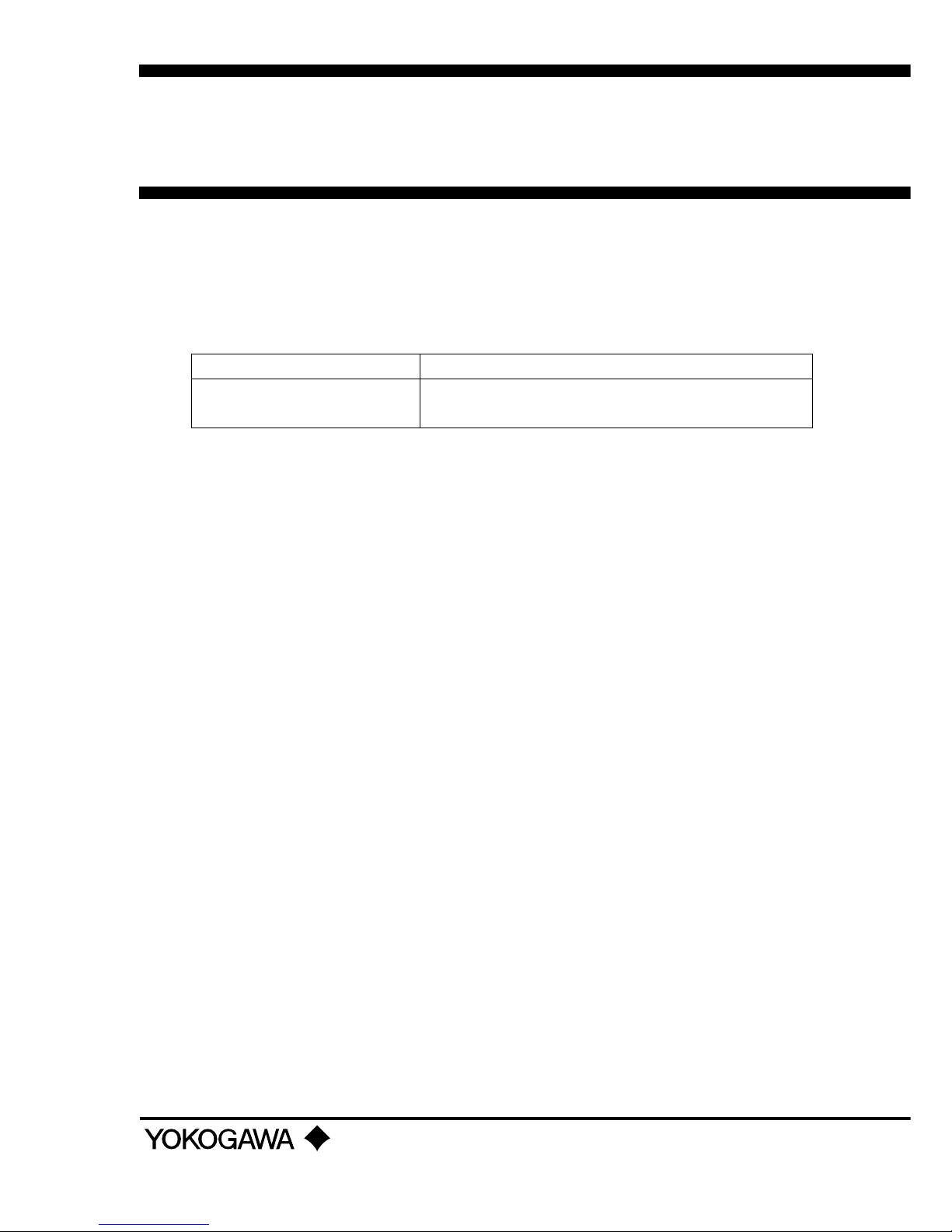
HAZARDOUS LOCATIONS DIVISION 1
50 cm Max.
Sealing Fitting
Conduit
Non-hazardous
Location
Equipment
42 V DC Max.
4 to 20 mA DC
Signal
NON-HAZARDOUS
LOCATIONS
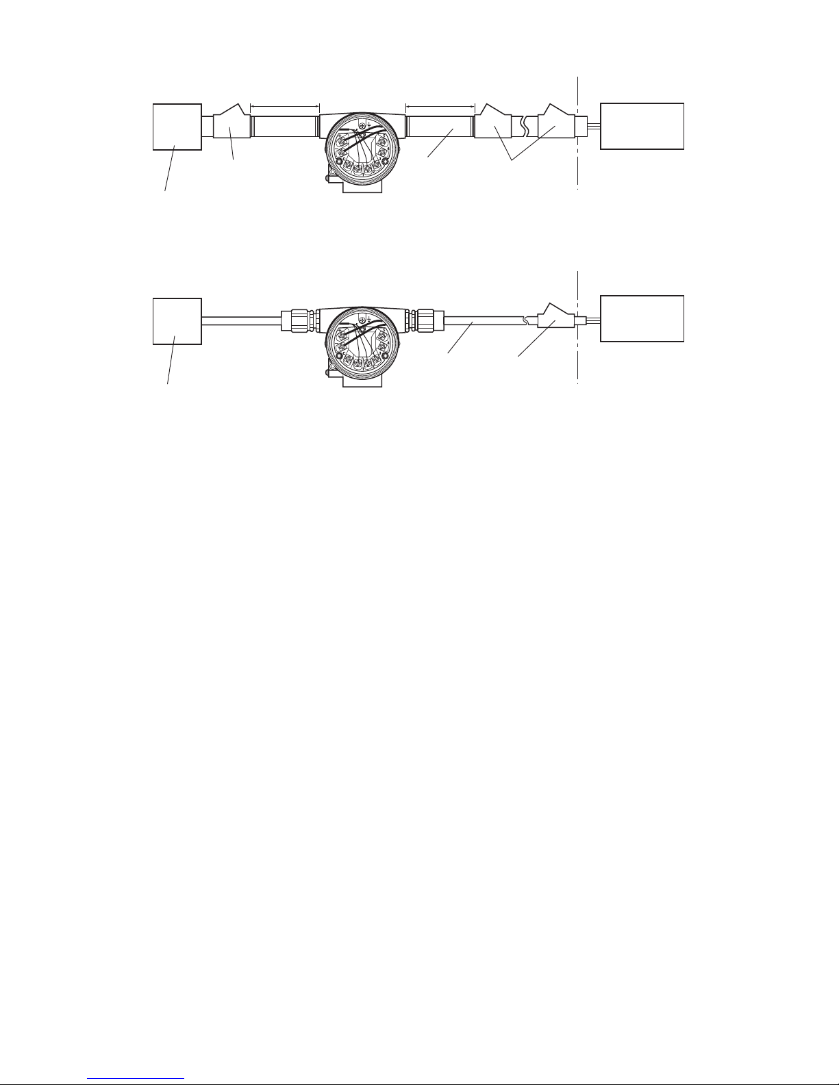
HAZARDOUS LOCATIONS DIVISION 2
Sealing Fitting
Sealing Fitting
50 cm Max.
Certified/Listed Temper ature Sensor
Explosionproof Class I, Groups C and D
Dustignitionproof Class II, Groups E, F and G, Class III
Wiring method shall be suitable for the specified hazardous locations.
YTA Series
YTA Series
Conduit
F0203.EPS
Certified/Listed Temper ature Sensor
Explosionproof Class I, Groups C and D
Dustignitionproof Class II, Groups E, F and G, Class III
Wiring method shall be suitable for the specified hazardous locations.
2.7.2 CENELEC ATEX (KEMA) Certification
Model YTA110/KU2, YTA310/KU2 and YTA320/
KU2 temperature transmitters can be selected the type
of protection (CENELEC ATEX(KEMA) Intrinsically
Safe or CENELEC ATEX(KEMA) Flameproof or
CENELEC ATEX Type of Protection “n”) for use in
hazardous locations.
Note 1. For the installation of this transmitter,
once a particular type of protection is
selected, any other type of protection
cannot be used. The installation must be
in accordance with the description about
the type of protection in this instruction
manual.
Note 2. In order to avoid confusion, unnecessary
marking is crossed out on the label other
than the selected type of protection when
the transmitter is installed.
(1) Technical Data
a) CENELEC ATEX (KEMA) Intrinsically Safe
Type
Caution for CENELEC ATEX (KEMA) Intrinsically
safe type
Note 1. Model YTA110/KU2, YTA310/KU2 and
YTA320/KU2 temperature transmitters for
potentially explosive atmospheres:
• No. KEMA 02ATEX1026X
• Applicable Standard: EN 50014, EN 50020, EN
50284
• Type of Protection and Marking code: II 1G EEx ia
IIC T5, T4
• Temperature Class: T5, T4
• Ambient Temperature: –40 to 70°C for T4, –40 to
50°C for T5
• Enclosure: IP67
Note 2. Electrical Data
• In type of explosion protection intrinsic safety II 1G
EEx ia IIC only for connection to a certified
intrinsically safe circuit with following maximum
values:
• [Supply circuit]
Ui = 30 V Ii = 165 mA
Pi = 900 mW
Effective internal capacitance, Ci = 20 nF
Effective internal inductance, Li = 660 µH
• [Sensor circuit]
Uo = 8.6 V Io = 30 mA
Po = 70 mW
Max. allowed external capacitance, Co = 3 µF
Max. allowed external inductance, Lo = 20 mH
Note 3. Installation
• All wiring shall comply with local installation
requirements. (Refer to the installation diagram)
Note 4. Maintenance and Repair
• The instrument modification or parts replacement by
other than authorized representative of Yokogawa
Electric Corporation is prohibited and will void
KEMA Intrinsically safe Certification.
Page 3

IM 01C50B01-01E
2-6
2. NOTES ON HANDLING
Note 5. Special condition for safe use
•Because the enclosure of the Temperature Transmitter is made of aluminium, if it is mounted in an area
where the use of category 1G apparatus is required,
it must be installed such, that, even in the event of
rare incidents, ignition source due to impact and
friction sparks are excluded.
Tr ansmitter
Supply
Safety Barrier
*1
Hazardous
Location
Nonhazardou
s
Location
+
–
+
–
[Installation Diagram]
F0208.EPS
Sensor
1
2
3
4
5
*1: In any safety barriers used the output current must be limited by
a resistor “R” such that Imaxout-Uz/R.
b) CENELEC ATEX (KEMA) Flameproof Type
and Dust Ignition Proof Type
Caution for CENELEC ATEX (KEMA) Flameproof
Type and Dust Ignition Proof Type
Note 1. Model YTA110/KU2, YTA310/KU2 and
YTA320/KU2 temperature transmitters
are applicable for use in hazardous
locations:
• No. KEMA 07ATEX0130
• Applicable Standard: EN 60079-0, IEC 60079-1,
EN 61241-0, EN 61241-1
• Type of Protection and Marking Code: II 2G Ex d
IIC T6/T5, II 2D Ex tD A21 IP67 T70°C, T90°C
• Ambient Temperature for Gas Atmospheres:
–40 to 75°C (T6), –40 to 80°C (T5)
• Ambient Temperature for Dust Atmospheres:
–40 to 65°C (T70°C), –40 to 80°C (T90°C)
• Enclosure: IP67
Note 2. Electrical Data
• Supply voltage: 42 V dc max.
• Output signal: 4 to 20 mA
Note 3. Installation
• All wiring shall comply with local installation
requirement.
• The cable entry devices shall be of a certified
flameproof type, suitable for the conditions of use.
Note 4. Operation
•Keep strictly the “WARNING” on the label on the
transmitter.
WARNING: AFTER DE-ENERGIZING, DELAY
5 MINUTES BEFORE OPENING.
WHEN THE AMBIENT TEMP. ⭌
70⬚C, USE THE HEATRESISTING
CABLES OF HIGHER THAN 90⬚C.
• Take care not to generate mechanical spark when
access to the instrument and peripheral devices in
hazardous location.
Note 5. Maintenance and Repair
• The instrument modification or parts replacement by
other than authorized representative of Yokogawa
Electric Corporation is prohibited and will void
KEMA Flameproof Certification.
c) CENELEC ATEX Type of Protection “n”
WARNING
When using a power supply not having a nonincendive circuit, please pay attention not to
ignite in the surrounding flammable atmosphere.
In such a case, we recommend using wiring
metal conduit in order to prevent the ignition.
Caution for CENELEC ATEX Type of Protection “n”
Note 1. Model YTA110/KU2, YTA310/KU2 and
YTA320/KU2 temperature transmitters for
potentially explosive atmospheres:
• Applicable standard: EN60079-15:2005
• Referential standard: IEC60079-0:2004,
IEC60079-11:1999
EN60529:1991
• Type of Protection and Marking Code: II 3G Ex nL
IIC T5, T4
• Temperature Class: T5, T4
• Ambient Temperature: –40 to 50°C for T5, –40 to
70°C for T4
• Enclosure: IP67
Note 2. Electrical Data
[Supply circuit]
Ui = 30 V
Effective internal capacitance, Ci = 20 nF
Effective internal inductance, Li = 660 µH
[Sensor circuit]
Uo= 8.6 V Io = 30 mA Po = 70 mW
Max. allowed external capacitance, Co = 3 µF
Max. allowed external inductance, Lo = 20 mH
Note 3. Installation
• All wiring shall comply with local installation
requirements. (refer to the installation diagram)
Page 4

IM 01C50B01-01E
7-5
7. GENERAL SPECIFICATIONS
Factory setting (䉫)
T0705.EPS
Tag No.
Input sensor type
Lower bound of calibration range
Upper bound of calibration range
Unit of calibration range
Damping constant
Sensor burnout
Output when transmitter fails
Left blank if not specified in order
“Pt100, 3-wire” if not specified in order
“0” if not specified in order
“100” if not specified in order
“°C” if not specified in order
2 seconds
High side (110%, 21.6 mA DC)
*1
High side (110%, 21.6 mA DC)
*2
*1: When option code C1 is specified, Low takes effect (–2.5%, 3.6mADC).
*2: When option code C1 is specified, Low takes effect (–5%, 3.2mADC or less).
7.2 Model and Suffix Codes
Model Basic Specification Codes Description
YTA110
YTA310
YTA320
Temperature transmitter (1 input type)
High precision temperature transmitter (1 input type)
High precision temperature transmitter (2 input type)
Output
signal
–D . . . . . . . . . . . . . . . . . . . .
–E . . . . . . . . . . . . . . . . . . . .
–F . . . . . . . . . . . . . . . . . . . .
4 to 20mA DC output, BRAIN communication type
4 to 20mA DC output, HART communication type
FOUNDATION Fieldbus communication type
*1
A . . . . . . . . . . . . . . . . . Always A
Electrical
connection
0 . . . . . . . . . . . . . . .
2 . . . . . . . . . . . . . . .
3 . . . . . . . . . . . . . . .
4 . . . . . . . . . . . . . . .
G1/2 female
1/2 NPT female
Pg13.5 female
M20 female
Built-in indicator
D . . . . . . . . . . . .
N . . . . . . . . . . . .
Digital indicator
None
Mounting bracket
B . . . . . . . . .
SUS304 Stainless steel 2-inch horizontal pipe mounting *2
SUS304 Stainless steel 2-inch vertical pipe mounting *2
None
D . . . . . . . . .
Additional specifications
/ Additional specifications
T0703.EPS
. . . . . . . . . . . . . . . . . . . . . .
. . . . . . . . . . . . . . . . . . . . . .
. . . . . . . . . . . . . . . . . . . . . .
—
*1: Applicable for YTA320 only.
*2: Use bolts for wall mounting.
N . . . . . . . . .
7.3 Optional Specifications
Failure alarm up-scale: output status at CPU failure
and hardware error is 110%, 21.6 mA or more.
Sensor burnout is also set to ‘High’: 110%, 21.6 mA
䊊
C3
Failure alarm down-scale: output status at CPU
failure and hardware error is –5%, 3.2 mA or less.
Sensor burnout is also set to ‘Low’: –2.5%, 3.6 mA
Addition of Degree F and Degree R unit
Output signal low-side: –5 %, 3.2 mA DC or less.
Sensor burnout is also set to ‘Low’: –2.5 %, 3.6 mA DC
Housing Material: SCS14A Stainless steel
䊊
䊊
䊊
䊊
䊊
䊊
䊊
Epoxy resin coating
P7
P1
P2
E1
D2
C2
C1
A
X1
Munsell renotation code: NI1.5 Black
Munsell renotation code: 7.5BG4/1.5, Jade green
䊊
Power supply voltage: 10.5 to 32 V DC
Allowable current: Max. 6000A(1⫻40s),
repeating 1000A(1⫻40s) 100 times
Metallic silver
Munsell renotation code: 7.5R4/14 Red
䊊
⫻
䊊
䊊
Sensor matching function
*2
䊊
RTD Sensor matching function CM1
䊊
䊊
䊊
䊊
PR
䊊
䊊
䊊
䊊
䊊
䊊
NAMUR NE43
compliant
*2
Item Descriptions
Painting
Lightning protector
Code
Output signal low-side in
Transmitter failure
*2
Description into “Descriptor” parameter of HART protocol.
(max. 16 characters)
䊊CA䊊
Data Configuration
*2
Stainless Steel Housing
*1
Calibration Unit
Output signal limits:
3.8 mA to 20.5 mA
Amplifier cover only
Amplifier and Terminal covers
Color change
Coating change
T0704.EPS
YTA110
YTA310
YTA320
*1 : Not applicable with other option codes, except for A, C1, D2 and CM1.
*2 : Not applicable for output signal code F.
Page 5

IM 01C50B01-01E
7-6
7. GENERAL SPECIFICATIONS
[For Explosion Protected Types]
For FOUNDATION Fieldbus explosion protected type, see IM 01C50T02-01E.
CENELEC ATEX (KEMA) Intrinsically safe, Flameproof approval and Type n combination
[Intrinsically safe approval]
Applicable standard: EN 50014, EN 50020, EN 50284 Certificate: KEMA 02ATEX1026X
II 1G EEx ia IIC T4,T5 Ambient Temerature: -40 to 70°C for T4, -40 to 50°C for T5
Supply/Output circuit: Ui=30V, Ii=165mA, Pi=900mW, Ci=20nF, Li=660H
Input circuit: Uo=8.6V, Io=30mA, Po=70mW, Co=3F, Lo=20mH
Electrical Connection: 1/2 NPT female and M20 female*
1
[Flameproof and Dust Ignition Proof Approval]
Applicable Standard: EN 60079-0, IEC 60079-1, EN 61241-0, EN 61241-1
Certificate: KEMA 07ATEX0130
II 2G Ex d IIC T6/T5, II 2D Ex tD A21 IP67 T70°C, T90°C
Ambient Temperature for Gas Atmospheres: -40 to 75°C for T6, -40 to 80°C for T5
Ambient Temperature for Dust Atmospheres: -40 to 65°C for T70°C, -40 to 80°C for T90°C
Enclosure: IP67
Electrical Connection: 1/2 NPT female and M20 female*
1
[Type n approval]
Applicable standard: EN60079-15
Referential standard: IEC60079-0, IEC60079-11, EN60529:1991
II 3G Ex nL llC T4, T5 Ambient Temperature: -40 to 70⬚C for T4, -40 to 50⬚C for T5
Supply/Output circuit: Ui=30V, Ci=20nF, Li=660H
Input circuit: Uo=8.6V, Io=30mA, Po=70mW, Co=3F, Lo=20mH
Electrical Connection: 1/2 NPT female and M20 female*
1
CENELEC ATEX
(KEMA)
Factory Mutual (FM)
Item
Descriptions
Code
KU2
FM Explosionproof approval
Applicable standard: FM 3600, FM 3615, FM 3810, NEMA250
Explosionproof Class I, Division 1, Groups A, B, C and D;
Dust-ignitionproof for Class II/III, Division 1, Groups E, F and G.
“FACTORY SEALED, CONDUIT SEAL NOT REQUIRED.” Enclosure Rating: NEMA 4X
Temperature Class: T6 Ambient Temperature: -40 to 60⬚C (-40 to 140⬚F)
Electrical Connection: 1/2 NPT female*
2
FM Intrinsically safe, non-incendive and Explosionproof approval combination*
3
[Intrinsically safe/non-incendive approval]
Applicable standard: FM 3600, FM 3610, FM 3611, FM 3810
Intrinsically safe for Class I, II, III Division 1 Groups A, B, C, D, E, F and G.
Non-incendive for Class I, II, Division 2 Groups A, B, C, D, E, F and G Class III, Division 1.
Enclosure Type: 4X Temperature Class: T4 Ambient Temperature: -40 to 60⬚C (-40 to 140⬚F)
Supply: Vmax=30V, Imax=165mA, Pmax=0.9W, Ci=18nF, Li=730H
Sensor: Voc=9V, Isc=40mA, Po=90Mw, Ca=1F, La=10mH
[Explosionproof approval]
Applicable standard: FM 3600, FM 3615, FM 3810, NEMA250
Class I, Division 1, Groups A, B, C and D.;
Dust-ignitionproof for Class II/III, Division 1, Groups E, F and G.
"FACTORY SEALD, CONDUIT SEAL NOT REQUIRED." Enclosure Ratings: NEMA4X
Temperature Class: T6 Ambient Temperature: -40 to
60⬚C (-40 to 140⬚F)
Electrical Connection: 1/2NPT female*
2
FF1
FU1
*1 : Applicable for Electrical Connection Code 2 and 4.
*2 : Applicable for Electrical Connection Code 2.
*3 : Not applicable for Output Signal Code F.
T0706-1.EPS
CSA Intrinsically safe, non-incendive and Explosionproof approval combination*
3
[Intrinsically safe/non-incendive approval]
Applicable standard: C22.2 No0, C22.2 No0.4, C22.2 No25, C22.2 No94, C22.2 No142,
C22.2 No157, C22.2 No213 Certificate: 172608-0001053837
Intrinsically safe for Class I, Division 1, Groups A, B, C and D; Class II, Division 1, Groups
E, F and G; Class III, Division 1:
Non-incendive for Class I, Division 2, Groups A, B, C and D; Class II, Division 2, Groups E,
F and G; Class III, Division 1:
Enclosure Type 4X Temperature Class: T4, Ambient Temperature: -40 to 60⬚C,
Supply: Vmax=30V, Imax=165mA, Pmax=0.9W, Ci=18nF, Li=730H
Sensor input: Voc=9V, Isc=40mA, Po=0.09W, Ca=1F, La=10mH
Electrical Connection: 1/2 NPT female*
1
[Explosionproof approval]
Applicable standard: C22.2 No0, C22.2 No0.4, C22.2 No25, C22.2 No30, C22.2 No94,
C22.2 No142, C22.2 No157, C22.2 No213, C22.2 No1010.1 Certificate: 1089576
Explosionproof Class I, Div.1, Groups B, C and D, Class II, Groups E, F and G, Class III. For
Class I, Div.2 Locations “FACTORY SEALED, CONDUIT SEAL NOT REQUIRED”
Enclosure Type 4X Temperature Class: T4 Ambient Temperature: -40 to 60⬚C
Electrical Connection: 1/2 NPT female*
1
Canadian Standards
Association (CSA)
CU1
 Loading...