

Page 1

User ’s
Manual
Model WE430
Hydrazine Analyzer
IM 12Y18A03-01EN
IM 12Y18A03-01EN
1st Edition
Page 2
u Introduction
Thank you for purchasing the WE430 Hydrazine Analyzer.
This Instructor’s Manual contains all essential information for the user to make full use of WE430.
Please read the following respective documents before installing and using the WE430.
The related documents are listed as follows.
General Specications
Contents Document number Note
Model WE430 Hydrazine Analyzer GS 12Y18A03-01EN Online manual
“EN” in the document number is the language code.
User’s Manual
Contents Document number Note
WE410, WE420, WE430, WE440
WET CHEMISTRY ANALYZER
Safety Precautions and Protection of Environment
Model WE430 Hydrazine Analyzer IM 12Y18A03-01EN Online manual (This manual)
“EN” in the document number is the language code.
An exclusive User’s Manual might be attached to the products whose sux codes or option
codes contain the code “Z” (made to customers’ specications). Please read it along with this
manual.
IM 12Y18A00-01EN
i
Attached to the product
(printed manual)
You can download the latest documents from our website. Scan QR code.
http://www.yokogawa.com/an/WE400/download/
Media No. IM 12Y18A03-01EN 1st Edition : Oct. 2019 (YK)
All Rights Reserved Copyright © 2019, Yokogawa Electric Corporation
IM 12Y18A03-01EN 1st Edition : Oct. 04, 2019-00
Page 3

n Notes on Handling User’s Manuals
• Please provide the user’s manuals to your end users so that they can keep the user’s
manuals for convenient reference.
• Please read the information thoroughly before using the product.
• The purpose of these user’s manuals is not to warrant that the product is well suited to any
particular purpose but rather to describe the functional details of the product.
• No part of the user’s manuals may be transferred or reproduced without prior written
consent from YOKOGAWA.
• YOKOGAWA reserves the right to make improvements in the user’s manuals and product at
any time, without notice or obligation.
• If you have any questions, or you nd mistakes or omissions in the user’s manuals, please
contact our sales representative or your local distributor.
n Drawing Conventions
Some drawings may be partially emphasized, simplied, or omitted, for the convenience of
description.
Some screen images depicted in the user’s manual may have dierent display positions or
character types (e.g., the upper / lower case). Also note that some of the images contained in this
user’s manual are display examples.
ii
n Trademark Acknowledgments
• All other company and product names mentioned in this user’s manual are trademarks or
registered trademarks of their respective companies.
• We do not use TM or ® mark to indicate those trademarks or registered trademarks in this
user’s manual.
IM 12Y18A03-01EN 1st Edition : Oct. 04, 2019-00
Page 4
u Safety Precautions
n Safety, Protection, and Modication of the Product
• In order to protect the system controlled by the product and the product itself and ensure
safe operation, observe the safety precautions described in this user’s manual. We assume
no liability for safety if users fail to observe these instructions when operating the product.
• If this instrument is used in a manner not specied in this user’s manual, the protection
provided by this instrument may be impaired.
• If any protection or safety circuit is required for the system controlled by the product or for
the product itself, prepare it separately.
• Be sure to use the spare parts approved by Yokogawa Electric Corporation (hereafter
simply referred to as YOKOGAWA) when replacing parts or consumables.
• Modication of the product is strictly prohibited.
• The following safety symbols are used on the product as well as in this manual.
WARNING
This symbol indicates that an operator must follow the instructions laid out in this manual in order
to avoid the risks, for the human body, of injury, electric shock, or fatalities. The manual describes
what special care the operator must take to avoid such risks.
iii
CAUTION
This symbol indicates that the operator must refer to the instructions in this manual in order to
prevent the instrument (hardware) or software from being damaged, or a system failure from
occurring.
CAUTION
This symbol gives information essential for understanding the operations and functions.
NOTE
This symbol indicates information that complements the present topic.
This symbol indicates Protective Ground Terminal.
n Warning and Disclaimer
The product is provided on an “as is” basis. YOKOGAWA shall have neither liability nor
responsibility to any person or entity with respect to any direct or indirect loss or damage arising
from using the product or any defect of the product that YOKOGAWA can not predict in advance.
IM 12Y18A03-01EN 1st Edition : Oct. 04, 2019-00
Page 5

u CE marking products
n Authorized Representative in EEA
The Authorized Representative for this product in EEA is Yokogawa Europe B.V. (Euroweg 2,
3825 HD Amersfoort, The Netherlands).
n Identication Tag
This manual and the identication tag attached on packing box are essential parts of the product.
Keep them together in a safe place for future reference.
n Users
This product is designed to be used by a person with specialized knowledge.
n How to dispose the batteries:
This is an explanation about the EU Battery Directive. This directive is only valid in the EU.
Batteries are included in this product. Batteries incorporated into this product cannot be removed
by yourself. Dispose them together with this product.
iv
When you dispose this product in the EU, contact your local Yokogawa Europe B.V.oce.
Do not dispose them as domestic household waste.
Battery type: Manganese dioxide lithium battery
Notice: The symbol (see above) means they shall be sorted out and collected as ordained in the
EU Battery Directive.
IM 12Y18A03-01EN 1st Edition : Oct. 04, 2019-00
Page 6

Model WE430
Hydrazine Analyzer
IM 12Y18A03-01EN 1st Edition
CONTENTS
u Introduction ....................................................................................................i
u Safety Precautions ......................................................................................iii
u CE marking products ..................................................................................iv
1. General Information ................................................................................. 1-1
1.1 Principles of Operation .................................................................................... 1-2
1.2 Principles of Calibration ................................................................................... 1-4
1.2.1 Dynamic Two Point Calibration (DYN) ............................................... 1-4
1.2.2 Oine Calibration .............................................................................. 1-4
1.3 Fluidics Diagram ............................................................................................... 1-5
1.4 Glossary ............................................................................................................. 1-5
Toc-1
2. Analyzer Preparation ............................................................................... 2-1
2.1 Mounting and Plumbing Instructions ............................................................. 2-1
2.2 Electrical Wiring ................................................................................................ 2-3
2.3 Wiring the Analyzer ........................................................................................... 2-4
2.3.1 Terminal Assignments ........................................................................ 2-6
2.3.2 Electrode Wiring Assignments ........................................................... 2-6
2.4 Installation of Reagent and Diusion Tubing ................................................2-6
2.5 Installation of New Electrode Cables .............................................................. 2-7
2.6 Installation of a New Iodide Electrode ............................................................ 2-7
2.7 Installation of ATC Probe ................................................................................. 2-8
2.8 Installation of a New Reference Electrode ..................................................... 2-9
3. Analyzer Operation .................................................................................. 3-1
3.1 Use of the Setup Mode .....................................................................................3-3
3.2 Setup Mode Overview ...................................................................................... 3-4
3.3 Shutdown and Start-Up Procedure ............................................................... 3-25
4. Calibration ................................................................................................. 4-1
4.1 Calibration Setup .............................................................................................. 4-1
4.2 Dynamic Calibrator Operation ......................................................................... 4-2
4.3 Dynamic Calibrator and Syringe Setup .......................................................... 4-3
4.4 Performing a DYN Calibration ......................................................................... 4-3
4.5 Calibration Error Codes ................................................................................... 4-5
4.6 Calibration At Custom Concentrations Using DYN ...................................... 4-6
4.7 Dynamic Calibrator Check ............................................................................... 4-7
IM 12Y18A03-01EN 1st Edition : Oct. 04, 2019-00
Page 7

Toc-2
4.8 Oine Calibration Procedure .......................................................................... 4-7
5. Analyzer Maintenance ............................................................................. 5-1
5.1 Maintenance Schedule ..................................................................................... 5-1
5.2 Weekly Maintenance ......................................................................................... 5-1
5.3 Bi-Weekly Maintenance .................................................................................... 5-1
5.4 Monthly Maintenance .......................................................................................5-2
5.4.1 Calibration .......................................................................................... 5-2
5.4.2 Replacement of Sample Inlet Filter .................................................... 5-2
5.4.3 Polish Iodide Electrode ...................................................................... 5-2
5.4.4 Air Pump Check ................................................................................. 5-2
5.4.5 Replacement of Reagent and Diusion Tubing Assembly ................ 5-2
5.5 Yearly Preventive Maintenance ....................................................................... 5-4
5.5.1 Electrodes .......................................................................................... 5-4
5.5.2 O-ring Replacement ........................................................................... 5-4
5.5.3 Replacement of Restrictor Tubing .....................................................5-4
6. Troubleshooting ....................................................................................... 6-1
6.1 Diagnostics Mode .............................................................................................6-1
6.1.1 Calibration Log ................................................................................... 6-1
6.1.2 Error List ............................................................................................. 6-2
6.1.3 Measurement Log .............................................................................. 6-2
6.1.4 Status Log .......................................................................................... 6-3
6.1.5 Software Revision .............................................................................. 6-3
6.1.6 Electronics Serial Number ................................................................. 6-3
6.1.7 mV and Noise Measurements ........................................................... 6-3
6.1.8 mA Output Values .............................................................................. 6-3
6.1.9 Display Test ........................................................................................ 6-3
6.1.10 Keypad Test .......................................................................................6-4
6.2 Slope Problems ................................................................................................. 6-5
6.2.1 Low Slope .......................................................................................... 6-5
6.2.2 High Slope .......................................................................................... 6-5
6.2.3 Troubleshooting Matrix ......................................................................6-6
6.3 Error/Event Codes ............................................................................................6-7
6.4 Resetting the Analyzer ..................................................................................... 6-9
6.4.1 Hard Reset ....................................................................................... 6-10
6.4.2 Serial Number and Software Revision ............................................. 6-10
Revision Record .......................................................................................................i
IM 12Y18A03-01EN 1st Edition : Oct. 04, 2019-00
Page 8

<1. General Information>
1. General Information
This user guide covers the operation, maintenance and troubleshooting for the WE430 Hydrazine
analyzer, which oers unmatched reliability in analyzing oxygen scavengers in feedwater, boiler
water or at the economizer inlet.
n Introduction
Analyzer the oxygen scavenger content at points in the steam/water circuit where dissolved
oxygen control is critical. Residual oxygen scavengers must be carefully monitored to prevent
costly overdosing, yet allow enough of the reductant in the system for metal passivation.
Excess levels of certain oxygen scavengers decompose into ammonia, which increases system
alkalinity. Ecient control of oxygen scavengers depends on maintaining a predetermined safety
zone. The WE430 Hydrazine analyzer optimizes the uidic design with the sensing technology
to provide accurate and precise results with an almost instantaneous indication of oxygen
scavenger concentration changes.
The WE430 Hydrazine analyzer meets all of the criteria for accurate and dependable oxygen
scavenger monitoring and more. The WE430 analyzer incorporates innovative technologies that
include:
• Premium electrodes
• Marquee help screen
• Pump-less reagent addition and dynamic calibration system
1-1
l Markets
• Power
• Pulp and paper
• Chemical / petrochemical
l Applications
• Boiler water
• Feedwater
• Hydrazine
• Carbohydrazide
• DEHA and others
n Features and Benets
The WE430 Hydrazine analyzer is ideal for measuring and monitoring the critical oxygen
scavenger levels in feedwater, boiler water or economizer inlet. With limited maintenance
requirements and low reagent usage, the WE430 analyzer provides the highest level of
performance with easy of use.
• Measurement of oxygen scavenger concentrations in water using premium ion selective
electrode (ISE) technology.
• Accurate and precise measurements in the range of 0 ppb to 200 ppb for hydrazine:
• Reliable measurements and a wide measurement range with selectable resolution.
• Measures oxygen scavenger activity in aqueous solutions quickly, accurately and
economically.
• Premium reference and sensing electrodes:
• Superior accuracy and stability over a wide temperature range.
• Advanced ow cell design:
• Automatic sample handling and contamination control with no moving parts.
• Patented scrolling marquee:
• Intuitive menu-driven, digital user interface.
• Data log of previous measurements and calibration:
• View measurement, calibration and error history.
IM 12Y18A03-01EN 1st Edition : Oct. 04, 2019-00
Page 9

<1. General Information>
• Self diagnostics:
• Ease of maintainability.
• Password protection:
• Security and peace of mind for your operation.
• Auto-ranging electronics with an easy to read backlit LCD display:
• Analyzer determines the best range.
n Application Modes
The versatility of the WE430 Hydrazine analyzer allows the operator to set the analyzer to read
hydrazine, depending on the oxygen scavenger to be measured. Refer to Section 3.1, Use of the
Setup Mode for instructions on how to set the analyzer to read hydrazine.
l Hydrazine Application
Hydrazine Measuring Range: 0 ppb to 200 ppb as hydrazine
In high pressure boiler systems, hydrazine is added to react with dissolved oxygen present in the
system and a small amount of residual hydrazine is left behind. The residual hydrazine ensures
that small amounts of dissolved oxygen that enters the system through leakage will be removed.
Residual hydrazine should be carefully monitored to prevent costly overdosing.
Excess hydrazine may also decompose into ammonia, which increases sample alkalinity and
attacks copper alloy components. Ecient control of hydrazine depends on maintaining a
predetermined safety zone – typically 10 to 50 ppb.
1-2
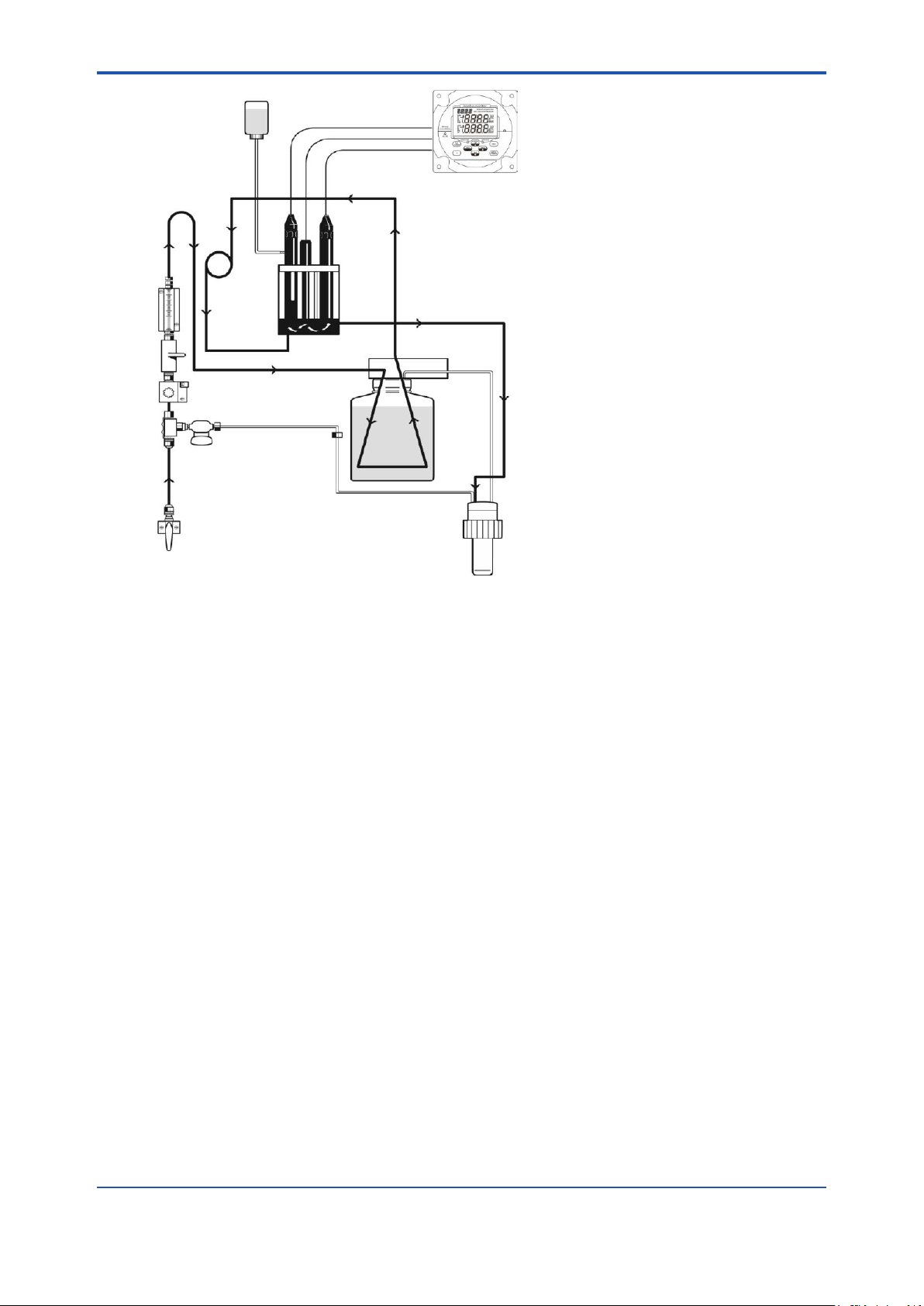
1.1 Principles of Operation
The sample enters the WE430 Hydrazine analyzer and passes through the inlet valve, bypass/
needle valve, inlet lter, pressure regulator, ow meter and into the restrictor tubing. The sample
then passes through the uid connector block into a reagent bottle and through a diusion tubing
assembly where pH adjustment takes place and iodine is added. The pH-adjusted sample then
ows back through the connector block into the reagent mixing loop where the oxygen scavenger
in the sample mixes with iodine reagent to form iodide. The sample then passes the iodide
electrode, reference electrode and temperature probe and ows into an atmospheric drain via the
diverter valve.
IM 12Y18A03-01EN 1st Edition : Oct. 04, 2019-00
Page 10
<1. General Information>
1-3
Figure 1.1 WE430 Schematic
The oxygen scavenger present in the sample reacts with the iodine to form iodide ion:
OS
+ X • I2 → 2X • I- + OS
red
ox
Where:
OS
= oxygen scavenger reduced
red
OSox = oxygen scavenger oxidized
The iodide sensing electrode responds logarithmically to changes in the resulting iodide ion
concentration. This response is described by the Nernst equation:
E = Eo + 2.3 (RT/nF) log (C/C
iso
)
Where:
E = measured electrode potential, mV
Eo = potential, when C equals C
iso
, mV
R = ideal gas constant
T = temperature of sample, degrees K
n = valence of ionic species (-1 for iodide ion)
F = Faraday’s constant
C = eective iodide concentration (activity)
C
= concentration (activity) of iodide ion where potential E is temperature independent
iso
(isopotential point)
E0 default: 44 mV
Low limit of E0: - 50 mV
High limit of E0: + 150 mV
Slope default: - 64.0 mV/decade
Slope range: - 75.0 mV/decade to - 40.0 mV/decade
IM 12Y18A03-01EN 1st Edition : Oct. 04, 2019-00
Page 11

<1. General Information>
The above equation indicates that the measured potential varies with both temperature and
the concentration of the ion of the interest. In order to eliminate error caused by uctuations in
sample temperature, the WE430 microprocessor constantly updates temperature corrections
from data supplied by the ATC probe.
From the Nernst equation, the theoretical response of a iodide ion selective electrode to a tenfold change in concentration at 25 °C is -59.16 mV. This is referred to as the electrode slope (S).
Most electrodes, however, do not exhibit a theoretical slope. Therefore, the analyzer is calibrated
to determine its actual value. Two standards are used to provide information necessary for the
microprocessor to compute the actual slope and E0 for use during sample analysis.
Acid is added to the sample to prevent a competing reaction from occurring:
-
3I2 + H2O → 5I- + IO
Maintaining acidic conditions prevents the release of iodide which would cause high apparent
reductant readings.
The pH adjustment and iodine addition are accomplished by the patented passive-diusion
process wherein the sample passes through a length of tubing in the reagent bottle that contains
the acid reagent and iodine. The reagent and iodine diuse through the tube wall and mix with
the sample. This passive method eliminates sample contamination problems due to reagent
contamination and makes the uid handling apparatus simple and reliable.
3
+ 6H
+
1.2 Principles of Calibration
1-4
Calibration procedures for analytical instruments are important and must be performed carefully.
The WE430 Hydrazine analyzer uses a dynamic two point calibration that utilizes advanced
electrode technology in combination with a dynamic calibrator.
1.2.1 Dynamic Two Point Calibration (DYN)
The dynamic two point calibration procedure provides maximum calibration accuracy and
requires the use of the dynamic calibrator. In addition to calculating the Eo value of the electrode,
as is done in an oine calibration procedure, this procedure determines electrode slope. To
perform a dynamic two point calibration, the WE430 analyzer is rst connected to a reductantfree sample stream. An appropriate diluted standard is prepared and then a syringe is lled
with the diluted standard and mounted on the calibrator. The calibrator is then mounted near
the analyzer and the syringe tubing is connected to the standard injection port. By adjusting the
calibrator pump settings, two dierent ow rates produce two known standards that are diluted
into the sample background. By pressing the appropriate keys on the analyzer when prompted,
the analyzer’s microprocessor completes the calibration. After allowing approximately 30 minutes
for the calibration solution to be ushed from the system, the WE430 analyzer can begin sample
measurement again.
1.2.2 Oine Calibration
In addition to a dynamic two point calibration, an oine calibration can be performed with
some oxygen scavengers. Since the oxygen scavenger concentration in feedwater is normally
controlled over a rather narrow range, usually an oine calibration procedure is sucient to
provide accurate results. The oine calibration procedure has the advantage of being quick and
easy to perform. If sample reductant concentrations are expected to vary widely from day to day
or if online verication of analyzer readings is desired, a dynamic two point calibration should be
performed.
The oine calibration feature of the WE430 analyzer allows the operator to adjust the analyzer to
values determined by alternate methods used in their laboratory such as a standard colorimetric
method.
IM 12Y18A03-01EN 1st Edition : Oct. 04, 2019-00
Page 12
<1. General Information>
The oine calibration is essentially a one point calibration. To perform an oine calibration, a
sample is taken from the bypass of the analyzer; the sample concentration value is stored in
memory; the sample is analyzed by an alternate method of choice; the previously stored reading
is adjusted to the lab method result; and the analyzer is then returned to the analysis mode. The
term “oine calibration” refers only to the fact that a sample from WE430 analyzer bypass is
taken “oine” for laboratory analysis; in fact, no downtime is experienced during the procedure
and the analyzer remains online throughout.
1.3 Fluidics Diagram
1-5
Figure 1.2 Fluidics Diagram
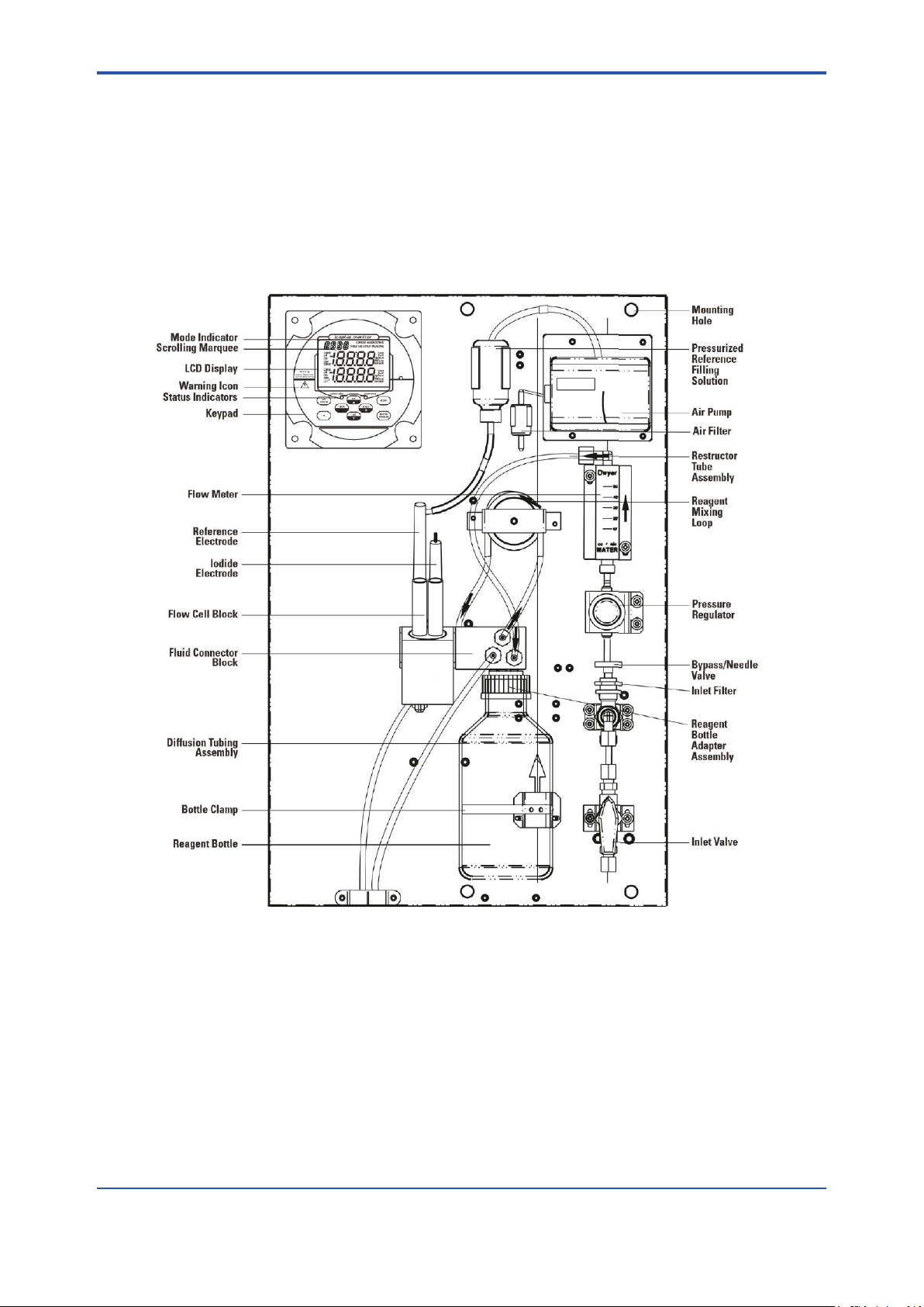
1.4 Glossary
Refer to Figure 1.2.
Inlet Valve
Accepts the sample stream via 1/4 inch NPTF connector. The operator must supply the
sample with a pressure between 8 and 100 psig.
Inlet Filter
60 micron stainless steel lter traps particulate matter in the sample stream.
Bypass/Needle Valve
Used to redirect ow in the bypass system.
IM 12Y18A03-01EN 1st Edition : Oct. 04, 2019-00
Page 13

<1. General Information>
Pressure Regulator
Adjusts ow of the incoming sample stream.
Flow Valve
Used to turn o ow to the ow cell.
Flow Meter
Measures the sample ow rate.
Restrictor Tube Assembly
Used in conjunction with the pressure regulator to maintain a steady sample ow rate.
Fluid Connector Block
Connects the reagent bottle to the sample stream and ow cell assembly.
Diusion Tubing Assembly
Semi-permeable tubing through which the reagent and iodine diuse into the sample.
Reagent Bottle
Contains the iodine solution and acid reagent that adjusts the sample pH.
Thumbscrew
Supports the reagent bottle.
Reagent Bottle Clamp
Holds the reagent bottle securely in place.
Reagent Mixing Loop
Mixes the iodine reagent with the oxygen scavenger in the sample to form iodide, which is
measured by the iodide sensing electrode.
Flow Cell
Contains the iodide sensing electrode, reference electrode and ATC probe.
Iodide Electrode
Senses iodide ions in the sample stream and produces an electrical potential dependent on
the oxygen scavenger concentration.
Reference Electrode
Provides a constant reference potential and completes the measurement circuit.
Pressurized Reference Electrode Filling Solution Bottle
Provides a constant ow of electrolyte solution through the reference electrode for
maximum stability.
Check Valve
Prevents the backow of electrolyte from the pressurized reservoir.
ATC Probe
Measures the sample temperature and inputs the data to the microprocessor for automatic
temperature compensation (ATC).
Standard Injection Port
Allows the connection of the dynamic calibrator tubing to the uid connector block during a
dynamic two point calibration.
Air Pump
Provides air to pressurize the lling solution bottle.
LCD Display
Provides digital readouts of concentration, temperature, millivolts and error codes.
Keypad
Consists of ve mode keys, four prompt indicator lights, two scroll keys and one key for
entering data. Mode and error indicators are also incorporated on keypad.
Status Indicator
Two LED lights that illuminate according to current status of the analyzer.
Green Light: Indicates that system is in correct working condition.
Yellow Light: Indicates a warning, system in hold or that maintenance is required.
Red Light: Indicates that something is seriously wrong.
1-6
NOTE
When either the yellow or red LED is lit, there may be an entry in the diagnostics mode that
indicates the error. The logging feature must be initiated in the setup mode. Refer to Section 3.1,
Use of the Setup Mode for instructions.
IM 12Y18A03-01EN 1st Edition : Oct. 04, 2019-00
Page 14
<2. Analyzer Preparation>
2. Analyzer Preparation
WARNING
The instructions provided in this userguide are recommendations from the manufacturer to
ensure safe and correct operation of the analyzer. If the analyzer is not used as recommended by
the manufacturer this can lead to incorrect operation or injury.
n Unpacking the Analyzer
YOKOGAWA analyzers are assembled, tested and packaged with great care.
1. Open the outer box. Remove the top four foam corner support pieces.
2. Open the inner box. This box should contain the analyzer and accessories. (Refer to IM
12Y18A00-01EN)
3. Remove the cardboard retaining shell by sliding it over the entire mounting board and the
analyzer.
4. Carefully remove the entire mounting board with analyzer from the inner box.
2-1
NOTE
Do not lift or pull the analyzer by the uidics or the electronic components.
Use the back panel to lift the analyzer system.
5. Unbolt the analyzer from the mounting board by removing the four mounting bolts with a
9/16’’ wrench. These bolts may be discarded.
6. Carefully place the analyzer at a convenient location until proper installation can be
completed.
2.1 Mounting and Plumbing Instructions
WARNING
Do not connect power prior to the mounting and plumbing of the analyzer.
IM 12Y18A03-01EN 1st Edition : Oct. 04, 2019-00
Page 15
<2. Analyzer Preparation>
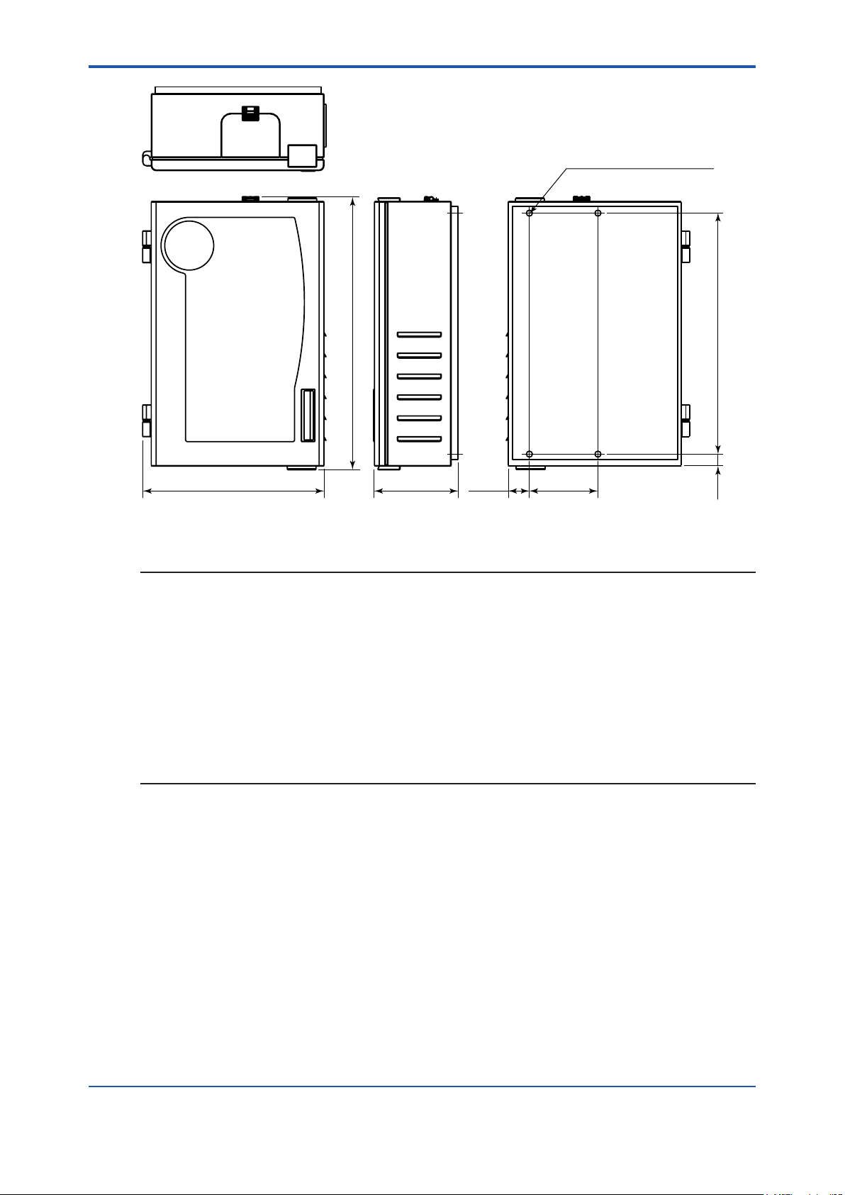
Mounting holes 4-ø12.7 (0.5)
2-2
Unit: mm (inch)
472 (18.6) 218 (8.6)
Figure 2.1 Mounting Dimensions
711
(28)
44 (1.75)
177.8 (7.0)
628.7
(24.75)
17
(0.68)
NOTE
• Select a site for the analyzer that allows it to be permanently bolted with ample height for
atmospheric drain operation. Be sure that there is ready access to the electronic controls,
calibration port and electrodes.
• A clearance of 15 inch (about 40 cm) must be allowed above the ow cell calibration port.
Insert the pipet vertically (not angled) during the calibration.
• The analyzer location must permit connections to a sample line, drain and AC power supply
and any connections for output devices.
• The analyzer should be mounted as close to the sampling point as possible. This ensures
the fastest possible response to a changing sample condition. Refer to the Appendix,
Sample Conditions section.
• For proper ow cell operation, the analyzer must be installed straight and level upon its
mounting location. Failure to level the analyzer may cause poor siphoning in the ow cell.
n Instructions
1. Prepare the mounting holes. Carefully lift the analyzer and bolt it into place. Do not lift the
analyzer by holding on to any of the plumbing or uid handling components.
2. Connect a waste line to the outlet of the analyzer, which is 3⁄4’’ NPT male. The waste
line should be connected to a drain of sucient capacity, 0.5 inch (1.27 cm) OD is
recommended.
3. Connect a sample line to the inlet of the analyzer, which is 1⁄4’’ NPT female. It is
recommended that a shuto valve be installed at the sampling point.
4. The analyzer must be mounted and leveled vertically for proper operation.
IM 12Y18A03-01EN 1st Edition : Oct. 04, 2019-00
Page 16
<2. Analyzer Preparation>
n Sample Requirements
Additional information is listed in the Appendix, Specications section.
Sample inlet connection
1/4” NPTF. If particulate matter is present in the sample, pre-ltration is necessary. The
60 micron stainless steel lter located after inlet valve will remove moderate amounts of
particulates.
Flow rate
40 mL/minute (nominal).
Pressure
8 to 100 psig.
Temperature
Temperature must be between 5 and 45°C.
Oxygen scavenger level
Oxygen scavenger levels are read directly in ppb or ppm, when calibrated with standard.
Sample alkalinity
Sample alkalinity should be less than 50 ppm CaCO3 equivalent.
2.2 Electrical Wiring
The warning icon highlights important information that should be strictly followed when using the
analyzer for your own safety. Failure to follow these instructions may result in injuries.
2-3
WARNING
Read and observe the following safety recommendations.
n Safety Requirements
• Prior to wiring, a switch or circuit breaker for disconnecting the analyzer from power supply
should be installed.
• The switch should be in close proximity to the analyzer and with easy reach of the
user.
• The switch should be marked as the disconnecting device for the analyzer.
• To reduce the risk of shock hazard, disconnect the power prior to opening the analyzer.
• Before connecting the analyzer to the main, make sure that the voltage lies within either
range: 100-120V 200mA / 200-240V 100mA; 50/60 Hz AC.
• Cutting o the power by disconnecting power source will not reset the analyzer. This
analyzer incorporates a non-volatile memory and will maintain calibration and settings after
power failure. Battery power is supplied to the display for the date and time functions.
• If a repair is required, or to arrange Return Material Authorization, call Response Center or
contact your local authorized dealer.
• Installation and wiring of the analyzer may only be carried out in accordance with applicable
local and national codes per this user guide.
• Be sure to observe the technical specications and input ratings.
n Warning Labels and Locations
WARNING
The following section provides important information that should be strictly followed when using
the analyzer for your own safety. Failure to follow these instructions may result in injuries.
IM 12Y18A03-01EN 1st Edition : Oct. 04, 2019-00
Page 17
<2. Analyzer Preparation>
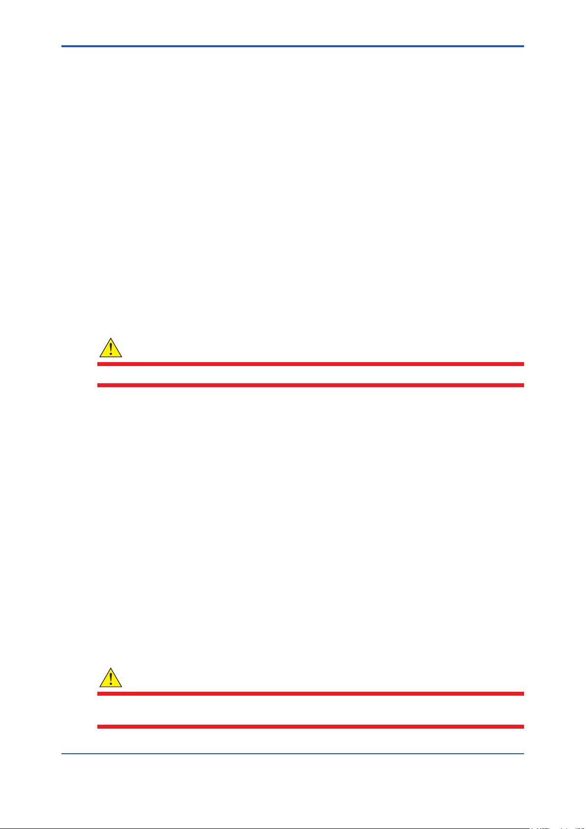
The safety warning icons are used in two locations on the analyzer.
• Faceplate – Refer to Figure 2.2.
Figure 2.2 Faceplate
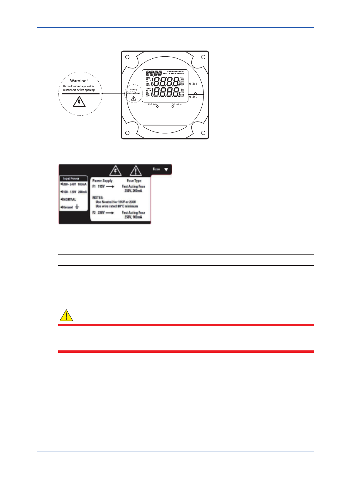
• Power supply – Refer to Figure 2.3.
2-4
Figure 2.3 Power Supply
NOTE
Replace the fuse only with a fuse of same rating.
2.3 Wiring the Analyzer
WARNING
Read and observe the following requirements. If you install the wrong fuse for your system, you
could damage the analyzer. Make sure that you select the correct fuse rating and discard the
additional fuses supplied in the fuse kit.
n Required Tools
• Options kit – includes fuses, cable glands, conduit tting and green screw terminal.
• Phillips head screwdriver.
• 2 mm blade at-head screwdriver.
IM 12Y18A03-01EN 1st Edition : Oct. 04, 2019-00
Page 18
<2. Analyzer Preparation>
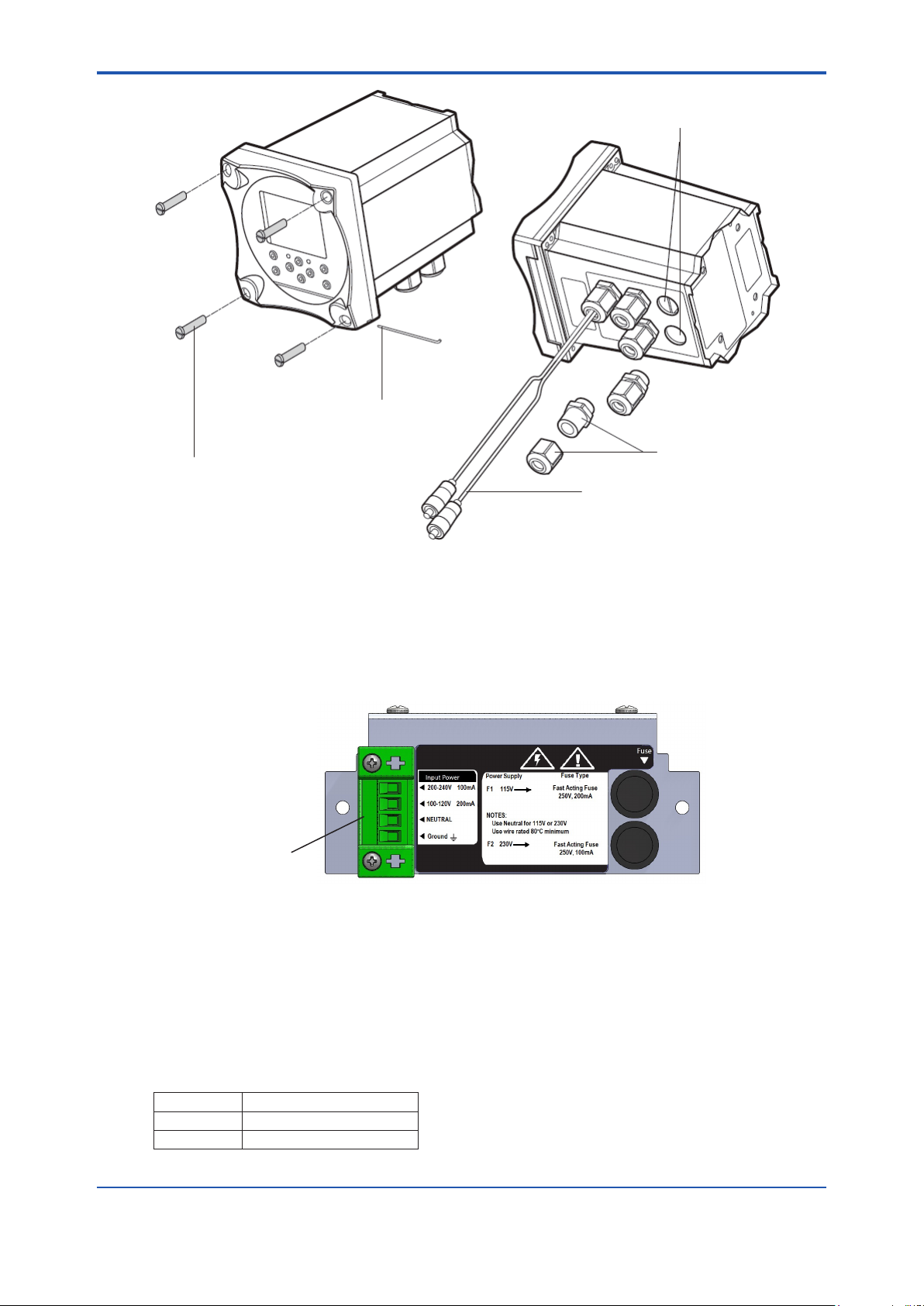
Power Cable
Hole Locations
Hinge Pin
Cable Glands
4 Captive Screws
Electrode Cables
2-5
Figure 2.4 Electronics Enclosure with Cable Glands
1. Open the faceplate – loosen the four screws using a Phillips head screwdriver. The
electronics faceplate will open via the hinge pin connection.
2. Remove one or two of the two unused cable glands as required for wiring power cable or
auxiliary connections. Power cable optional hole locations are shown in Figure 2.4.
3. Select and install the appropriate size cable gland or conduit tting as required.
4. Feed the power cable through the conduit or cable glands as required.
Terminal connector
Figure 2.5 Terminal Connector Location
5. Wire the power cable to the green screw terminal connector from the options kit. Select
correct terminal for hot conductor depending on line voltage, insert ground wire into the
correct terminal and connect the other cable to the neutral terminal. Refer to Figure 2.5 for
terminal connector location.
6. Plug the terminal connector into the power supply. Refer to Figure 2.3.
7. The universal power supply uses both fuses in the fuse kit. Install by inserting the fuse in the
fuse holder and secure it using the twist and lock method. The fuses are clearly labeled with
the appropriate voltages for your system. Refer to Figure 2.3 and Figure 2.5 for the correct
fuse holder positions. Refer to the table below for fuses required.
AC Voltage Fuse Rating
115V 200mA, 250V, Fast Acting
230V 100mA, 250V Fast Acting
IM 12Y18A03-01EN 1st Edition : Oct. 04, 2019-00
Page 19
<2. Analyzer Preparation>
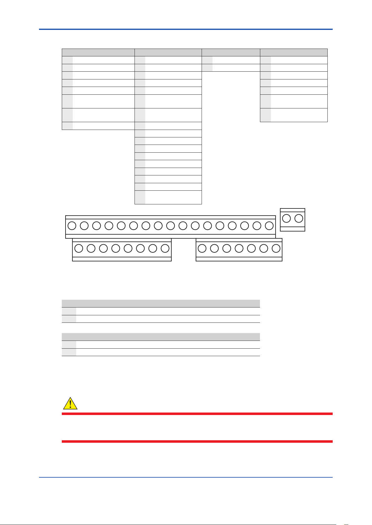
2.3.1 Terminal Assignments
Terminal Layout Terminal Layout Terminal Layout Terminal Layout
1 mA1 output 9 Relay 1 26 Sensing electrode 28 Do not connect
2 GND common ground 10 Relay 1 27 Do not connect 29 Do not connect
3 mA2 output 11 Relay 2 30 Preamp power
4 Air pump (ISE only) 12 Relay 2 31 Preamp ground
5 Air pump (ISE only) 13 Relay 3 32 Shield
6 Shield ground for
conductivity
7 Do not connect 15 Do not connect 34 Jumper to pin 26
8 Do not connect 16 Temperature ground
14 Relay 3 33 Shield
when using preamp
17 Temperature drive
18 Temperature sense
19 Solution ground
20 Conductivity drive +
21 Conductivity sense +
22 Conductivity sense 23 Conductivity drive 24 Reference electrode
25 Jumper to pin 24
when using preamp
2-6
26 27
9 10 11 12 13 14 15 16 17
1 2 3 4 5 6 7 8 28 29 30 31 32 33 34
Figure 2.6 Terminal Assignments
18 19 20 21 22 23 24 25
2.3.2 Electrode Wiring Assignments
Iodide Electrode
26 Sensing electrode Connect clear wire
33 Shield Connect black wire
Reference Electrode
24 Reference electrode Connect clear wire
32 Shield Connect black wire
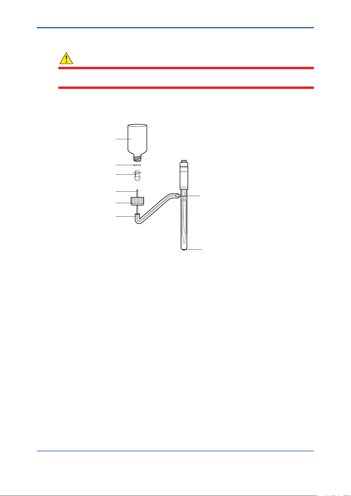
2.4 Installation of Reagent and Diusion Tubing
WARNING
The reagent is hazardous. Use protective glasses and gloves. Refer to the bottle label for
precautions and work in a fume hood or well-ventilated area. Avoid contact with skin or clothes. In
case of skin contact, ush skin immediately with water to prevent burns.
IM 12Y18A03-01EN 1st Edition : Oct. 04, 2019-00
Page 20
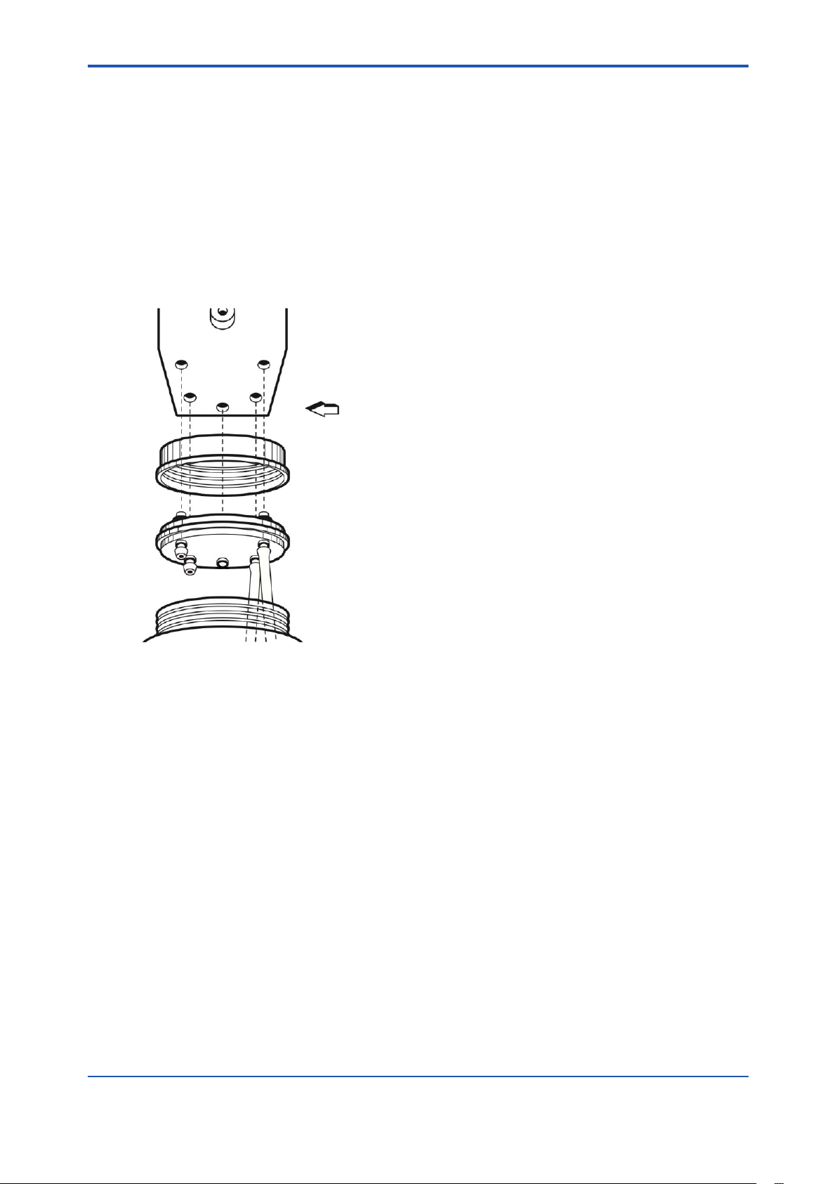
<2. Analyzer Preparation>
1. Support the bottom of the reagent bottle and release the holding clamp with one hand. Turn
the thumbscrew counterclockwise to release the reagent bottle. Unscrew the white bottle
cap and gray tubing connector assembly. The bottle that is supplied with the analyzer can
be used as a spare.
2. Take a new bottle of the reagent (Cat. No. 181811) to a well ventilated area, such as a
laboratory fume hood. Unscrew and remove the white cap on the bottle.
3. Connect the diusion tubing (Cat. No. 181860) to the tubing connector assembly. Place the
tubing assembly and cap into the bottle.
4. Replace the gray cap and screw the white cap on tightly.
5. Insert the four nipples on the top of the reagent bottle into the uid connector block.
6. Support the bottom of the reagent bottle with one hand and tighten the thumbscrew
clockwise.
7. Clamp the bottle to the uidics panel to secure it.
2-7
Figure 2.7 Reagent Bottle Assembly
2.5 Installation of New Electrode Cables
1. Unpack the electrode cables.
2. Feed the tinned wires through the cable gland assemblies with the holes (2 or 1).
3. Follow the terminal assignments shown in Figure 2.6 for the proper electrode cable wiring
location.
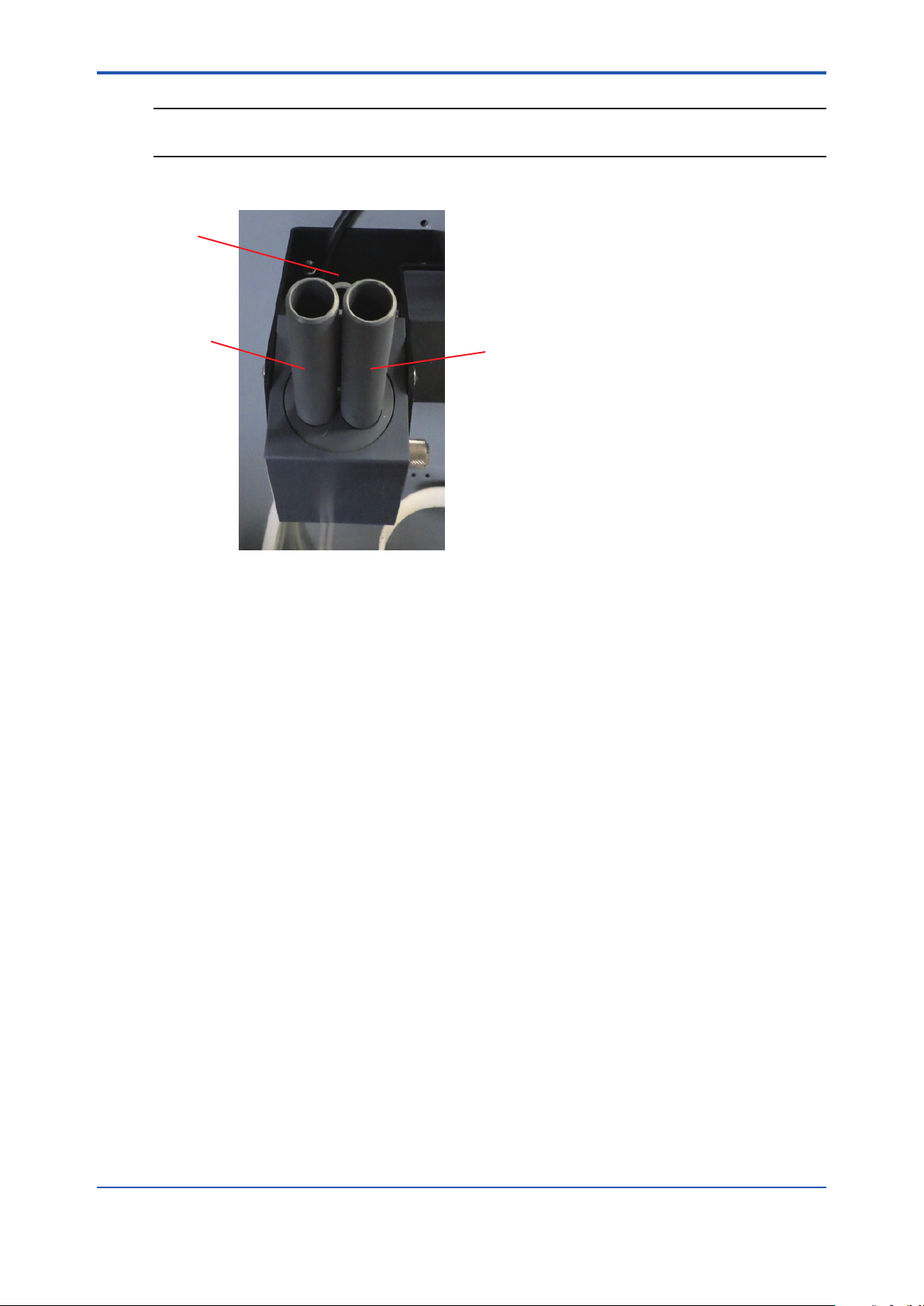
2.6 Installation of a New Iodide Electrode
The Iodide electrode (Part number: K9705CG) must be used in conjunction with the reference
electrode (Part number: K9705CH).
1. Unpack the iodide electrode (Part number: K9705CG) and carefully remove the protective
cap. Save the cap for future storage of the electrode. Use the electrode polishing strip to
gently polish the sensing surface of the iodide electrode for about 30 seconds.
2. Insert the Iodide electrode into its port in the ow cell cap. Refer to Figure 2.8 for the
location. Installation in the incorrect hole will cause calibration issues.
3. Plug the electrode cable marked “Sensing” into the top of the electrode. Be sure to
push back the black cap to verify a secure connection between the male and female pin
connection prior to tightening.
4. Tighten the screw cap connection to the cable.
IM 12Y18A03-01EN 1st Edition : Oct. 04, 2019-00
Page 21
<2. Analyzer Preparation>
NOTE
Do not twist the cable while tightening the connection. Twisting may cause damage requiring
premature replacement of the cable.
5. Wait at least one hour before calibrating the analyzer.
ATC
2-8
Sensor
Figure 2.8 Flow Cell Cap
Reference
2.7 Installation of ATC Probe
The automatic temperature compensation (ATC) probe is already connected to the correct
terminal for temperature upon delivery.
1. Insert the ATC probe into its port in the ow cell cap. Refer to Figure 2.8 for the location.
IM 12Y18A03-01EN 1st Edition : Oct. 04, 2019-00
Page 22
<2. Analyzer Preparation>
2.8 Installation of a New Reference Electrode
WARNING
Turn o the air pump prior to removing the reference electrode lling solution bottle. If the air
pump is left on, it will spatter lling solution as the bottle is removed.
1. Unpack the reference electrode (Part number: K9705CH) from the shipping box.
2. Carefully remove the protective caps from the bottom and sidearm of the reference
electrode. Save the caps for future storage of the electrode.
Reference Electrode
Filling Solutuin
Gasket
Tubing Bottle Adaptor
2-9
Small 1/8” Tubing Inside
Bottle Cap
Large 1/4” Tubing
Figure 2.9 Reference Electrode with Filling Solution
Electrode Sidearm
Ceramic Frit
3. Shake out as much of the ll solution as possible through the sidearm. Drain the ll solution
through the sidearm or use a pipet or syringe.
4. While passing the 1/8 inch tubing into electrode sidearm, slide the 1/4 inch tubing over the
sidearm. The outside tubing should extend 3/8 to 1/2 inches over sidearm. Refer to Figure
2.9.
5. Remove the cap and uid seal from reference electrode ll solution bottle (Cat. No. 181073).
Hold the bottle in an upright position. Check that the rubber gasket is properly aligned, and
then connect the cap end of the tubing assembly to the bottle. The 1/8 inch tubing should
extend into the bottle.
6. Hold the reservoir bottle above the electrode with the bottle cap end down. The electrode
should be horizontal with the sidearm pointing up. Gently shake the electrode to allow any
trapped air bubbles to rise into the bottle as the electrode lls with solution.
7. Dry o the ceramic frit on the base of the electrode with a lint-free wipe. Squeeze the bottle
for a few seconds. A small amount of lling solution should bead up on the frit surface,
indicating good lling solution ow. If no moisture is visible, the electrode is clogged and
should be cleaned or replaced.
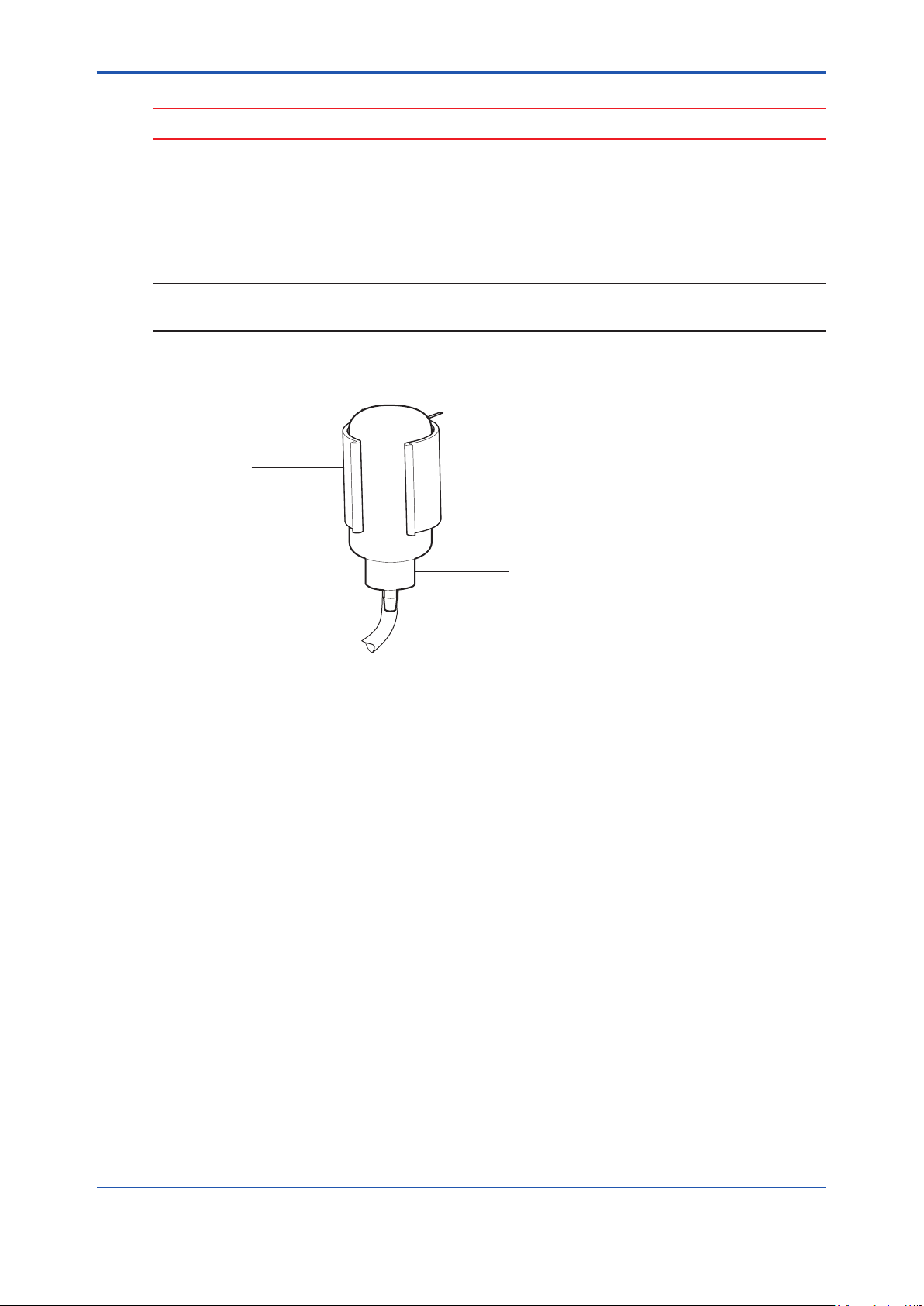
8. Invert the electrolyte bottle and snap it into the clip. Refer to Figure 2.10. Locate the
discharge tube of the air pump on the uidics panel. The end of the tubing has a hollow
push pin for pressurizing the reference reservoir. Puncture the base of the bottle with the
pin and push the pin down until its PVC base abuts the bottle. Mark and date the level of
lling solution in the reservoir. The electrolyte solution will begin to ow into the reference
electrode.
IM 12Y18A03-01EN 1st Edition : Oct. 04, 2019-00
Page 23
<2. Analyzer Preparation>
CAUTION
Failure to pressurize the lling solution bottle will lead to noisy and drifting output signals.
9. Plug the electrode cable marked “Reference” into the top of the electrode, and tighten the
screw cap. Be sure to push back the black cap to verify a secure connection between the
male and female pin connection prior to tightening.
10. Tighten the screw cap connection to the cable.
NOTE
Do not twist the cable while tightening the connection. Twisting may cause damage requiring
premature replacement of the cable.
11. Insert the reference electrode into its port in the ow cell cap. Refer Figure 2.8 for the
location.
Clip (on Panel)
2-10
Figure 2.10 Reference Mounting Clip
Bottle
IM 12Y18A03-01EN 1st Edition : Oct. 04, 2019-00
Page 24
<3. Analyzer Operation>
3. Analyzer Operation
n Description of Basic Controls
A
B
C
D
3-1
E
F
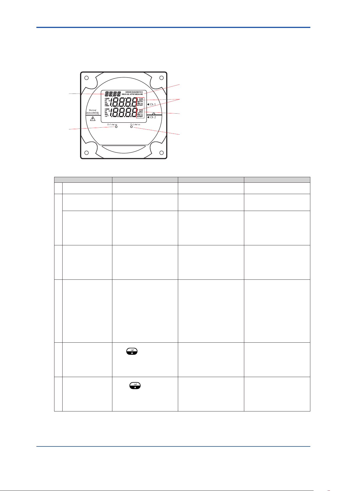
Figure 3.1 Faceplate
Parameter Location on Display Options Default
A Mode Indicator Top right corner of display HOLD, CAL, SETUP,
B Marquee Display Top left corner of display Analyzer provides prompts
Temperature Display Celsius In the measure mode, if an
C Main Data Display Middle line and bottom line
D Measurement Units Left and right side of middle
E Channel 1 Status
Indicator
F Channel 2 Status
Indicator
of display
and bottom display lines
Below display screen, to the
left of
Below display screen, to the
right of
MEASURE, DIAGNOSTIC
for operator using the
scrolling message
ISE board: concentration
pH/mV board: pH or mV
Conductivity board:
conductivity, resistivity,
salinity, concentration or
TDS
ISE board: ppm or ppb,
auto-ranging pH/mV board:
pH or mV
Conductivity board: μS/cm
or mS/cm (conductivity),
MΩ-cm (resistivity), SAL1
or SAL2 in the marquee
(salinity), PCT1 or PCT2 in
the marquee (concentration)
and TDS1 or TDS2 in the
marquee (TDS)
Green LED indicates that
channel is OK
Orange LED indicates a
channel warning
Red LED indicates a
channel failure
Green LED indicates that
channel is OK
Orange LED indicates a
channel warning
Red LED indicates a
channel failure
MEASURE
ATC probe is connected
the default is the actual
measured temperature and
if no ATC probe is connected
the default is 25 °C
Depends on type of board
installed and selected
measurement parameter
Depends on type of board
installed and selected
measurement parameter
At initial installation, the
red LED indicates that the
electrode or probe needs to
be installed and calibrated.
At initial installation, the
red LED indicates that the
electrode or probe needs to
be installed and calibrated.
IM 12Y18A03-01EN 1st Edition : Oct. 04, 2019-00
Page 25
<3. Analyzer Operation>
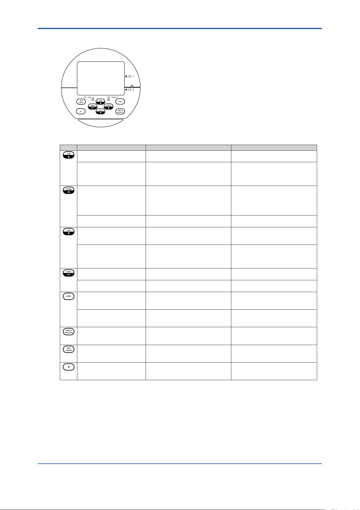
n Description of Keypad Icons
Figure 3.2 Keypad Icons
Key Parameter/Mode Action Operational Selections
Enters calibration mode Calibration mode with operator
Scrolls up digit numbers
Scrolls up through a list of
options in setup and cal
modes
Enters setup mode System setup mode at the last
Moves to the nextdigit Use to edit values When moved to nal digit, the
Enters test mode Use to advance through sequence
Scroll down digit numbers
Scroll down through a list
of options in setup and cal
modes
Enters log view mode Use to view data in calibration,
+/- function Enters negative/positive sign when
Enter function Use to accept value orselection
Enter function
(in test mode only)
Exit to measure function Use to exit setup or cal modes and
Last screen function Use in setup and test modes to
Decimal point function Use to set the decimal point position
prompts
Use to edit numeric values
Use to select available options
parameter used by the operator
of displays DIAGNOSTICS will
appear in top right of screen
Use to edit numeric values
Use to select available options
measure and status logs
editing numbers
displayed on screen and store value
or selection in memory
Use in test mode to
displayadditional information for
selected menus
enter the measure mode
return to the previous screen or
menu
in certain menus with numbers that
require a decimal point
Depends on type of board installed
0 through 9 selectable by digit,
rst digit sometimes selectable 0
through 19
PASS, DATE, TIME, LOG,RSET,
DISP, CH1, CH2, MDL, MEAS,
HOLD, TCMP, TADJ, ALRM, mA1,
mA2, mADJ, TEST, CAL, PH,
COND, DYN
system will wrap around to rst digit
0 through 9 selectable by digit,
rst digit sometimes selectable 0
through 19
Analyzer automatically enters
measure mode when rst turned on
and after calibration
3-2
IM 12Y18A03-01EN 1st Edition : Oct. 04, 2019-00
Page 26

<3. Analyzer Operation>
3.1 Use of the Setup Mode
Before the rst sample measurements can be taken, the setup mode should be programmed
and a successful calibration must be performed by the operator and stored in the memory of the
analyzer.
n Navigating Tips for the Setup Mode
• Press to enter the setup mode.
• SETUP appears in the mode indicator screen.
• HOLD is displayed while in the setup mode.
• The analyzer will enter the setup mode at the last menu that was used by the operator.
• Press and to loop through the menu options.
• Press to select the desired menu option and set the menu option parameters.
• Press and to:
• Scroll between On and OFF for the selected menu option.
• Scroll and set the rst digit value to 0 through 19.
• Scroll and set the remaining digit values to 0 through 9.
• Press to move to the next digit (scroll right) to set each digit value (4 digits maximum).
• Press to save the entered parameter for the selected menu option.
• Press to exit the current screen and return to the previous screen.
• Press to exit the setup mode and return to the measure mode. If is pressed,
will not return the operator to the setup mode. The operator must reenter the setup mode by
pressing .
3-3
n Using Password Protection
The default password is 0000 – indicates password protection has not been activated.
System password:
Management secured password protection of setup mode and calibration process.
Calibration password:
Operator secured password for protection of calibration process only.
If password(s) are activated:
• System prompts operator to enter system password:
• Marquee: ENTER PASSWORD
• Main display top: PASS
• Main display bottom: 0000 (ashing)
• Correct password – Allows operator to enter setup mode for custom programming options.
• Incorrect password – Password incorrect or not entered correctly.
• System password:
• Marquee: SYSTEM PASS INCORRECT
• Main display: E035
• Calibration password:
• Marquee: CAL PASS INCORRECT
• Main display: E034
• Verify password and re-enter it.
If password(s) are de-activated:
• System enters the setup mode at the last setup menu option used by the operator.
• Marquee: Flashes current menu option
• Main display: SEL SCrn
IM 12Y18A03-01EN 1st Edition : Oct. 04, 2019-00
Page 27

<3. Analyzer Operation>
3.2 Setup Mode Overview
The setup mode features programmable menu options. The order of the menu options is
dependent on the direction the operator scrolls by pressing or . The menu options are
listed below by pressing .
n General Setup Mode Menu Options
The following menu options are displayed in the main setup mode of one and two channel
analyzers.
l PASS
Set either of two password options:
• System password – Setup settings protected, accessed by authorized operators only
• Calibration password – Calibration menu data is protected, accessed by authorized
operators only
• Default password is 0000 – Disables both passwords
• Forgot your password? Contact Response Center
l DATE
3-4
Set the date in US or Europe format:
• Enter month, day and year
• Default date – System will continue to keep date and time due to battery back up, operator
must set in accordance to local time zone
• If the battery is removed, the system will show 01/01/2000
l TIME
Set the time:
• Enter hour and minutes in 24 hour format
• Default time – System will continue to keep date and time due to battery back up, operator
must set in accordance to local time zone
• If the battery is removed the system will show 00:01
l LOG
Set the data logging interval for measure log (calibration and error logs are accessed in the test
mode):
• Set the log interval as hour:minute (HH:MM)
• Default log interval is 00:00 – logging disabled
• Minimum log interval is 1 minute, maximum log interval is 99 hours and 59 minutes
l RSET
Reset the analyzer to factory defaults for setup parameters:
• Used to troubleshoot the system (a hard reset can be performed if the keypad and software
are not responding, refer to Section 6.4, Resetting the Analyzer)
WARNING
Resetting the analyzer will lose all stored information including relay, logs and calibration settings.
IM 12Y18A03-01EN 1st Edition : Oct. 04, 2019-00
Page 28

<3. Analyzer Operation>
l DISP
Set the automatic lighting options for the backlit display:
• AUtO – Brightness will change in response to ambient light source
• On – Backlit display is always on
• OFF – Backlit display is always o
• Default display – AUtO
l MDL
Sets the analyzer to the hydrazine application mode.
NOTE
Changing the application mode will reset the analyzer, restore the default parameters and clear
any saved calibration information.
l MEAS
Set the number of signicant digits, mV display option and concentration units displayed when in
the measure mode:
• Set the number of signicant digits displayed measure mode
• Scroll through 2, 3 or 4 signicant digits
• Default signicant digits – 3
• Enable mV values to be displayed on the second line
• Scroll between On or OFF
• Default mV setting – OFF
• Set the displayed concentration units
• Scroll through AUtO (automatically ranges from ppb to ppm), PPb (parts per billion,
ppb), or PP (parts per million, ppm)
• Default displayed concentration units – AUtO
3-5
l HOLD
Set the time that the system will remain on hold before the actual measurements are displayed
after a calibration:
• Once the hold time expires, the system implements any programmed changes to settings in
the setup mode
• After a calibration, the hold function allows the operator to rinse the electrodes prior to
recording actual measurement values
• Default hold time – 30 minutes
l TADJ
Adjust the temperature reading from the ATC probe by ± 5.0 °C:
• Default adjustment – 0.0 °C
IM 12Y18A03-01EN 1st Edition : Oct. 04, 2019-00
Page 29

<3. Analyzer Operation>
l ALRM
Set up to three alarms – high, low and an error signaling contact:
• Relays 1 and 2 (rLY1, rLY2) are normally open dry contacts used to set high and low alarms
for measurement values
• rLY1 and rLY2 options – OFF, HI, LO
• Relay 3 (rLY3) is normally a closed contact that can be dedicated to errors (will close if
power to analyzer is lost), this alarm is inuenced by calibration, errors and oine or hold
status
• rLY3 options – OFF, CAL, HOLD, Err
• Default setting for all alarms – OFF
Setup Menu
Vertsion 5.14
3-6
mA1
mA range
0-20/4-20
Sout Type
LOG/LIN
Sout Lo
select value
Sout Hi
select value
Sout Type
LOG/LIN
Sout Lo
Select value
Sout Hi
Select value
mA2
mA range
0-20/4-20
mA Type
Sensor/Temp
Tout Lo
Select value
Tout Hi
Select value
Back to
Setup
menu
Back to
l mA1
Set the mA1 analog current output:
• Scroll between 4-20 mA or 0-20 mA current signals
• The outputs share a common return, but are isolated from the main circuitry of the
analyzer
• Default output current: 4-20 mA
• Scroll between logarithmic (LOg) and linear (LIn) scale.
• Set the low and high limits for the sensor output (SOUt)
• Default – 1.0 ppb (low) and 100 ppb (high)
Setup
menu
IM 12Y18A03-01EN 1st Edition : Oct. 04, 2019-00
Page 30

<3. Analyzer Operation>
l mA2
Set the mA2 analog current output:
• Scroll between 4-20 mA or 0-20 mA current signals
• The outputs share a common return, but are isolated from the main circuitry of the
analyzer
• Default output current: 4-20 mA
Select Sensor or Temperature for this output (SEnS and tEnP)
If Sense -
• Scroll between logarithmic (LOg) and linear (LIn) scale for SOUt
• Set the low and high limits for the sensor output (SOUt)
• Default – 1.0 ppb (low) and 100 ppb (high)
If Temp -
• Set the low and high limits for the temperature output (tOUt)
• Default – 5.0 °C (low) and 45.0 °C (high)
l mADJ
Set the mA oset adjustment value for the mA1 and mA2 outputs:
• Select the OUT1 or OUT2 output
• Scroll the numeric oset value and positive or negative oset value
• Default mA oset – 00.0 mA
3-7
l TEST
Test relays and analog output lines (DIAGNOSTICS will appear in the mode indicator):
• Method to activate/deactivate relays and outputs to be tested
• Verify the accuracy of the analog outputs when used with an external loop calibrator
• Provides the values and settings for the mA output and relays
• mA output
• 4-20
• The low and high values represented by mA1 and mA2
• Relay status
• Set RLY1, RLY2 and RLY3 status to OFF or On
l CAL
Set calibration frequency in hours:
• High limit is 19999 hours
• Low limit is 00000 hours
• Default setting – 720 hours
l DYN
Set values for customized Dynamic Two Point Calibration (DYN):
• Programmable for the analyzer ow rate; concentration (ppm), percent ow and range of
standard 1 and concentration (ppm), percent ow and range of standard 2
• Default analyzer ow rate: 40 mL/minute
• Default standard concentration: 2 ppm
• Default standard 1 (Std1) percent ow (Hydrazine): 99.9%
• Default standard 1 (Std1) range: x/100
• Default standard 2 (Std2) percent ow (Hydrazine): 52.5%
• Default standard 2 (Std2) range: x/10
IM 12Y18A03-01EN 1st Edition : Oct. 04, 2019-00
Page 31

<3. Analyzer Operation>
3-8
Default Operator Action Scrolling Marquee Main Display Notes
Default Operator Action Scrolling Marquee Main Display Notes
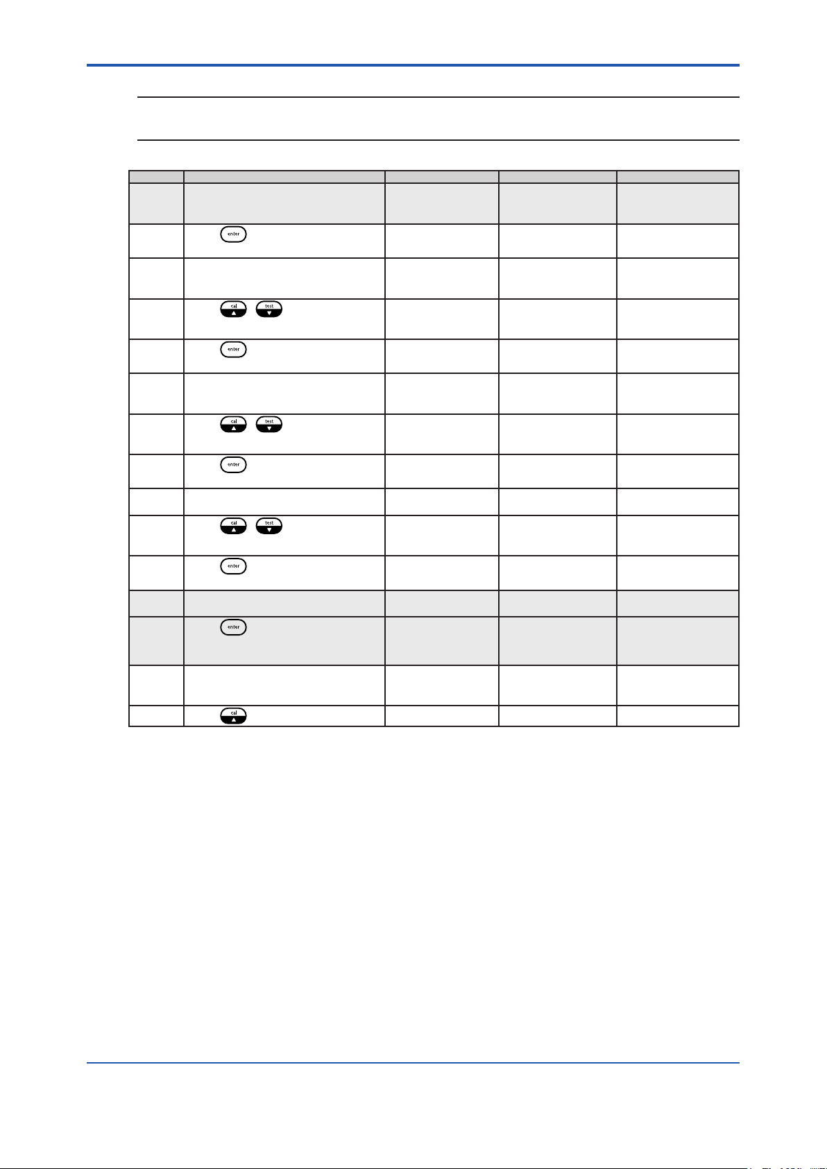
SETUP (One Channel Analyzer)
Press to enter setup mode
• SETUP appears as the mode indicator in
the mode window
• HOLD is displayed while in the setup
mode
• The system will enter the setup mode at
the last saved menu option
Press to loop through the menu options
Press to select the desired menu option
and enter the submenu to customize setup
parameters
SETUP (Two Channel Analyzer)
Press to enter setup mode
• SETUP appears as the mode
indicator in the mode window
• HOLD is displayed while in the
setup mode
• The system will enter the setup
mode at the last saved menu
option
PASS
DATE
TIME
LOG
RSET
DISP
CH1
MEAS
HOLD
TADJ
ALRM
mA1
mA2
mADJ
TEST
CAL
DKA
PASS
DATE
TIME
LOG
RSET
DISP
MEAS
HOLD
TADJ
ALRM
mA1
mA2
mADJ
TEST
CAL
DKA
SEL SCrn The displayed menu
SEL SCrn
SEL SCrn
SEL SCrn
SEL SCrn
SEL SCrn
SEL SCrn
SEL SCrn
SEL CH1
SEL CH1
SEL CH1
SEL CH1
SEL CH1
SEL CH1
SEL CH1
SEL CH1
SEL CH1
SEL CH1
options depend on
the measurement
capability of the
analyzer.
The list of menu
options shown for
CH2 are examples
only. The displayed
menu options for
CH2 depend on
the measurement
capability of the
channel.
If only one board
is installed in the
analyzer, CH1 and
CH2 will not be
shown in the scrolling
marquee and all of the
menu options will be
listed in the main setup
mode.
Press to loop through the menu
options
Press to select the desired
menu option and enter the submenu
to customize setup parameters
CH2
MDL
HOLD
TCMP
TADJ
ALRM
mA1
mA2
mADJ
TEST
CAL
PH
SEL SCrn
SEL CH2
SEL CH2
SEL CH2
SEL CH2
SEL CH2
SEL CH2
SEL CH2
SEL CH2
SEL CH2
SEL CH2
SEL CH2
IM 12Y18A03-01EN 1st Edition : Oct. 04, 2019-00
Page 32

<3. Analyzer Operation>
3-9
Default Operator Action Scrolling Marquee Main Display Notes
0 0 0 0 SET-UP NEW
0 0 0 0 SET-UP NEW
PASS PASS (ashing) SEL
Press to set new passwords
SYSTEM
PASSWORD
Press / to set the rst digit
Press to move to the next digit
Press / to set the values
of the remaining digits and press
to move through the remaining
digits
Press to accept the system
password and advance to the
next screen to set the calibration
password
Press / to set the rst digit
Press to move to the next digit
Press / to set the valuesof
the remaining digits and press
to move through the remaining digits
Press to accept thecalibration
password and return to the main
setup mode
Press to scroll to the next menu
SET-UP NEW
SYSTEM
PASSWORD
CALIBRATION
PASSWORD
SET-UP NEW
CALIBRATION
PASSWORD
PASS (ashing) SEL
SCrn
PASS
# # # #
(rst digit ashing)
PASS
# # # #
(change ashing
digit)
PASS
# # # #
(rst digit ashing)
PASS
# # # #
(change ashing
digit)
SCrn
Do not scroll rst digit
above 9
Do not scroll rst digit
above 9
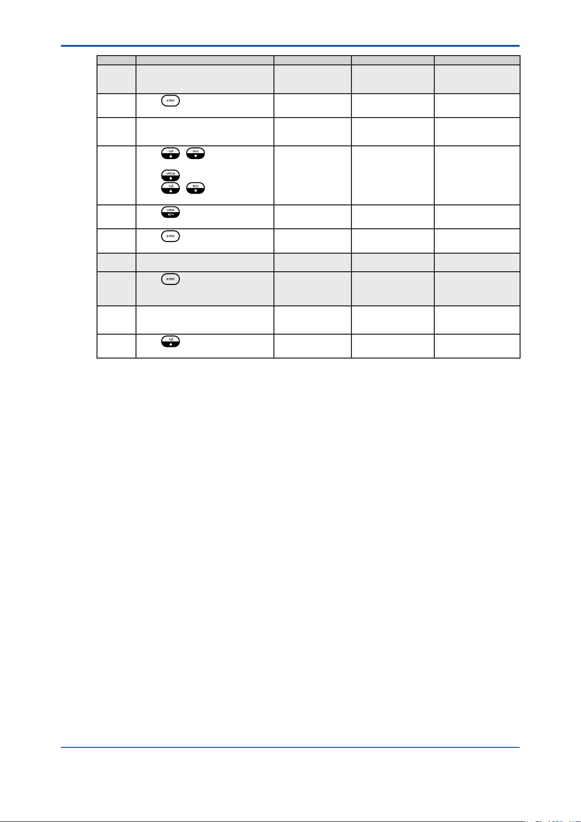
Default Operator Action Scrolling Marquee Main Display Notes
US SET USA OR
01/01/
2000
DATE DATE (ashing) SEL
Press to set the date
EUROPEAN
Press / to scrollbetween
US and EUrO
Press to accept the setting and
advance to the next screen
Press / to set the rst digit
Press to move to the next digit
Press / to set the valuesof
the remaining digits and press
to move through the remaining digits
Press to accept the date
setting and return to the main setup
mode
Press to scroll to the next menu
SET USA OR
EUROPEAN
ENTER DATE MM/
DD/YYYY (US)
or
ENTER DATE DD/
MM/YYYY (EUrO)
ENTER DATE MM/
DD/YYYY (US)
or
ENTER DATE DD/
MM/YYYY (EUrO)
DATE
(ashing)
SCrn
US (ashing)
US or EUrO
(ashing)
##.## (Month. Day)
20## (Year)
or
##.## (Day. Month)
20## (Year)
(rst digit ashing)
##.## (Month. Day)
20## (Year)
or
##.## (Day. Month)
20## (Year)
(change ashing
digit)
SEL
SCrn
IM 12Y18A03-01EN 1st Edition : Oct. 04, 2019-00
Page 33

<3. Analyzer Operation>
3-10
Default Operator Action Scrolling Marquee Main Display Notes
00:01 ENTER 24HR TIME
Default Operator Action Scrolling Marquee Main Display Notes
00:00 SET LOG TIME IN
TIME TIME
Press to set the time
Press / to set the rst digit
Press to move to the next digit
Press / to set the valuesof
the remaining digits and press
to move through the remaining digits
Press to accept the time setting
and return to the main setup mode
Press to scroll to the next menu
LOG LOG
Press to set the log interval
Press / to set the rst digit
Press to move to the next digit
Press / to set the values of
the remaining digits and press
to move through the remaining digits
Press to accept the log setting
and return to the main setup mode
Press to scroll to the next menu
(ashing)
HOUR/MINUTE
ENTER 24HR TIME
HOUR/ MINUTE
TIME
(ashing)
(ashing)
HOUR/ MINUTE
SET LOG TIME IN
HOUR/ MINUTE
LOG
(ashing)
SEL
SCrn
##:## (hour : minute)
(rst digit ashing)
##:## (hour : minute)
(change ashing digit)
SEL
SCrn
##:## (hour : minute)
LOg
(rst digit ashing)
##:## (hour : minute)
LOg
(change ashing
digit)
SEL
SCrn
Set in 24hour time
format
SEL
SCrn
To disable the log
enter 0000 for the log
interval
The minimum log
interval is 1 minute
and the maximum log
interval is 99 hours
and 59 minutes
WARNING
The reset command will erase all operator settings, logs and calibration data. The analyzer will
need to be set up and calibrated again before it can resume operation.
IM 12Y18A03-01EN 1st Edition : Oct. 04, 2019-00
Page 34

<3. Analyzer Operation>
3-11
Default Operator Action Scrolling Marquee Main Display Notes
RSET RSET
Press to reset theanalyzer
To Reset the Analyzer:
Press
Press
Press
When the reset is complete, the system
will return to the measure mode. The
operator will need to re-enter the setup
mode to continue programming the
setup parameters.
Press to return to the setup mode.
To Abort the Reset:
Press to return to the main setup
mode
Press to scroll to the next menu
(ashing)
PUSH TEST
VIEWENTER TO
RESET
PUSH TEST
VIEWENTER TO
RESET
PRESS TEST VIEW
ENTER TO RESET
RSET
(ashing)
SEL
SCrn
rSEt
?
rSEt
?
rSEt
?
SEL
SCrn
This command resets
all previously set
parameters to factory
default values. Use
this command only
to set the analyzer to
original factory setup
values.
WARNING
Resetting the analyzer will erase all stored information including relay, logs and calibration
settings.
Default Operator Action Scrolling Marquee Main Display Notes
AUtO BACK LITE LItE
DISP DISP
Press to set the lighting option for
the backlit display
Press / to scroll through
AUtO, OFF and On settings
Press to accept the display setting
and return to the main setup mode
Press to scroll to the next menu
(ashing)
BACK LITE LItE
DISP
(ashing)
SEL
SCrn
AUtO
(ashing)
AUtO, OFF or On
(ashing)
SEL
SCrn
NOTE
The following menu options are for analyzers with two modules installed only. If two channels
are used, select the channel number in the main setup mode (CH1 or CH2) and additional menu
options will be displayed.
IM 12Y18A03-01EN 1st Edition : Oct. 04, 2019-00
Page 35

<3. Analyzer Operation>
3-12
Default Operator Action Scrolling Marquee Main Display Notes
Default Operator Action Scrolling Marquee Main Display Notes
CH1 CH1
Press to set the channel 1
specic menus in the setup mode
Press to loop through the
channel specic menu options
Press to select a menu option
and customize the parameter (refer
to the menu option displays that are
shown on the following pages for
detailed instructions)
Press to scroll tothe next menu
CH2 CH2
Press to set the channel 2
specic menus in the setup mode
Press to loop through the
channel specic menu options
Press to select a menu option
and customize the parameter (when
a pH/ORP or conductivity board is
installed on channel 2, refer to the
Thermo Scientic Orion 2100 Series
pH/ORP Analyzer and Conductivity
Analyzer User Guide for detailed
instructions on the menu option
displays)
Press to scroll to the next menu
(ashing)
MEAS
(ashing)
CH1
(ashing)
(ashing)
MDL
(ashing)
CH2
(ashing)
SEL
SCrn
SEL CH1
SEL
SCrn
SEL
SCrn
SEL
CH2
SEL
SCrn
CH1 will not be
shown in scrolling
marquee if only one
board is installed
CH2 will not be
shown in scrolling
marquee if only one
board is installed
Default Operator Action Scrolling Marquee Main Display Notes
PH SELECT
MDL MDL
Press to set the measurement
parameter for the analyzer
Press / to scroll between
HYdr and ELI and select the desired
measurement parameter
Press to accept the
measurement setting and return to
the main setup mode
Press to return to the channel
specic menu options in the setup
mode
Press to scroll to the next menu
(ashing)
HYDRAZINE
SELECT
HYDRAZINE
CH1 or CH2
(ashing)
MDL
(ashing)
SEL
SCrn
HYdr
(ashing)
HYdr
(ashing)
SEL
SCrn
SEL
SCrn
IM 12Y18A03-01EN 1st Edition : Oct. 04, 2019-00
SEL CH1 or SEL CH2
on main display of
two channel analyzer
Displayed for two
channel analyzer
Action required for
two channel analyzer
Page 36
<3. Analyzer Operation>
NOTE
Changing the application mode will reset the analyzer, restore the default parameters and clear
any saved calibration information.
3-13
Default Operator Action Scrolling Marquee Main Display Notes
3 SET NUMBER
OFF SHOW MV ON
AUtO SELECT ISE UNIT UnIt AUtO
MEAS MEAS
Press to set measure
parameters
Press / to scroll through
2, 3 and 4
Press to accept the setting and
advance to the next screen
Press / to scroll between
OFF and On
Press to accept the setting and
advance to the next screen
Press / to scroll through
AUtO, PPb and PP
Press to accept the setting and
return to the main setup mode
Press to return to the channel
specic menu options in the setup
mode
Press to scroll to the next menu
(ashing)
OF SIGNIFICANT
DIGITS
SET NUMBER
OF SIGNIFICANT
DIGITS
SINGLE CHANNEL
DISPLAY
SHOW MV ON
SINGLE CHANNEL
DISPLAY
SELECT ISE UNIT UnIt
CH1 or CH2
(ashing)
MEAS
(ashing)
SEL
SCrn
SIg 3
(ashing)
SIg 2, 3 or 4
(ashing)
OFF
(ashing)
OFF or On (ashing)
(ashing)
AUtO, PPb or PP
(ashing)
SEL
SCrn
SEL
SCrn
SEL CH1 or SEL CH2
on main display of
two channel analyzer
PP is used as an
abbreviation for ppm
Displayed for two
channel analyzer
Action required for
two channel analyzer
SEL CH1 or SEL CH2
on main display of
two channel analyzer
IM 12Y18A03-01EN 1st Edition : Oct. 04, 2019-00
Page 37

<3. Analyzer Operation>
3-14
Default Operator Action Scrolling Marquee Main Display Notes
00:30 ENTER HOLD TIME
LASt ENTER HOLD
21.0 ENTER FIXED
OFF HOLD TO 22mA
HOLD HOLD
Press to set the hold time
Press / to set the rst digit
Press to move to the next digit
Press / to set the values
of the remaining digits and press
to move through the remaining
digits
Press to accept the setting and
advance to the next screen
Press / to scroll between
LASt and USEr
Press to accept the setting and
advance to the next screen
Press / to set the rst digit
Press to move to the next digit
Press / to set the values
of the remaining digits and press
to move through the remaining
digits
Press / to set the rst digit
Press to move to the next digit
Press / to set the values
of the remaining digits and press
to move through the remaining
digits
Press to accept the setting and
advance to the next screen
Press / to scroll between
OFF and On
Press to accept the setting and
return to the main setup mode
Press to return to the channel
specic menu options in the setup
mode
Press to scroll to the next menu
(ashing)
HOUR/MINUTE
ENTER HOLD TIME
HOUR/MINUTE
STATELAST OR
USER VALUE
ENTER HOLD
STATELAST OR
USER VALUE
USER VALUE IN mA
ENTER FIXED
USER VALUE IN mA
ENTER FIXED
USER VALUE IN mA
WHEN ERROR
HOLD TO 22mA
WHEN ERROR
CH1 or CH2
(ashing)
HOLD
(ashing)
SEL
SCrn
##:##
(rst digit ashing)
##:##
(change ashing
digit)
LASt
(ashing
LASt or USEr
(ashing)
##.#
(rst digit ashing)
##.#
(change ashing
digit)
##.#
(change ashing
digit)
OFF
(ashing)
OFF or On (ashing)
SEL
SCrn
SEL
SCrn
SEL CH1 or SEL CH2
on main display of
two channel analyzer
Displayed ifUSEr was
selected in previous
screen
Action required if
USEr was selected in
previous screen
Action required if
USEr was selected in
previous screen
Action required if
USEr was selected in
previous screen
Displayed fortwo
channel analyzer
Action required for
two channel analyzer
SEL CH1 or SEL CH2
on main display of
two channel analyzer
IM 12Y18A03-01EN 1st Edition : Oct. 04, 2019-00
Page 38
<3. Analyzer Operation>
3-15
Default Operator Action Scrolling Marquee Main Display Notes
0.0 C TEMPERATURE
TADJ TADJ
Press to set the temperature
adjustment value
Press / to set the rst
digit
Press to move to the next digit
Press / to set the value
of the next digit
Press to set a positive or
negative temperature value
Press to accept the setting
and return to the main setup mode
Press to return to the channel
specic menu options in the setup
mode
Press to scroll to the next
menu
(ashing)
ADJUSTMENT
TEMPERATURE
ADJUSTMENT
TEMPERATURE
ADJUSTMENT
CH1 or CH2
(ashing)
TADJ
(ashing)
SEL
SCrn
AdJ
#.# c
(rst digit ashing)
AdJ
#.# c
(change ashing
digit)
AdJ
- #.# c
SEL
SCrn
SEL
SCrn
SEL CH1 or SEL CH2
on main display of
two channel analyzer
The maximum
temperature
adjustment is ± 5.0 °C
Displayed for two
channel analyzer
Action required for
two channel analyzer
SEL CH1 or SEL CH2
on main display of
two channel analyzer
IM 12Y18A03-01EN 1st Edition : Oct. 04, 2019-00
Page 39

<3. Analyzer Operation>
3-16
Default Operator Action Scrolling Marquee Main Display Notes
OFF SELECT ALARM 1
100 ppb Set the HI or LO value for rLY1:
OFF SELECT ALARM 2
1 ppm Set the HI or LO value for rLY1:
OFF SELECT
ALRM ALRM
Press to set the alarms
Press / to scroll through
OFF, HI and LO
Press to accept the setting and
advance to the next screen
Press to move the decimal point
Press / to set therst digit
Press to move to thenext digit
Press / to set the values of
the remaining digits and press
to move through the remaining digits
Press to accept the setting and
advance to the next screen
Press / to scroll through
OFF, HI and LO
Press to accept the setting and
advance to the next screen
Press to move the decimal point
Press / to set the rst digit
Press to move to the next digit
Press / to set the values of
the remaining digits and press
to move through the remaining digits
Press to accept the setting and
advance to the next screen
Press / to scroll through
OFF, CAL, HOLd and Err
Press to accept the setting and
return to the main setup mode
Press to return to the channel
specic menu options in the setup
mode
Press to scroll to the next menu
(ashing)
HIGH LOW OR OFF
SELECT ALARM 1
HIGH LOW OR OFF
ENTER VALUE rLY1
HIGH LOW OR OFF
SELECT ALARM 2
HIGH LOW OR OFF
ENTER VALUE rLY2
CALIBRATION
HOLD
ERROR OR OFF
SELECT
CALIBRATION
HOLD
ERROR OR OFF
CH1 or CH2
(ashing)
ALRM
(ashing)
SEL
SCrn
rLY1 OFF
(ashing)
rLY1
OFF, HI or LO
(ashing)
##.##
(change ashing
digit)
rLY2 OFF
(ashing)
rLY2
OFF, HI or LO
(ashing)
##.##
(change ashing digit
rLY3 OFF
(ashing)
rLY3
OFF, CAL, HOLd
or Err
(ashing)
SEL
SCrn
SEL
SCrn
SEL CH1 or SEL CH2
on main display of
two channel analyzer
Displayed ifHI or LO
was selected for rLY1
in previous screen
Action required if HI
or LO was selected
for rLY1 in previous
screen
Displayed ifHI or LO
was selected for rLY2
in previous screen
Action required if HI
or LO was selected
for rLY2 in previous
screen
Displayed for two
channel analyzer
Action required for
two channel analyzer
SEL CH1 or SEL
CH2 on main display
of two channel
analyzer
IM 12Y18A03-01EN 1st Edition : Oct. 04, 2019-00
Page 40

<3. Analyzer Operation>
Conguring the analog output mA1
Default Operator Action Scrolling Marquee Main Display Notes
4-20
1 ppb mA SENSOR
100 ppb mA SENSOR
mA1 mA1
Press to set the analog output
1
Press / to scroll between
4-20 and 0-20
Press to accept the setting and
advance to the next screen
Press / to scroll between
LOg and LIn
Press to accept the setting and
advance to the next screen
Press to move the decimal
point
Press / to set the rst digit
Press to move to the next digit
Press / to set the values
of the remaining digits and press
to move through the remaining
digits
Press to accept the setting and
advance to the next screen
Press to move the decimal
point
Press / to set the rst digit
Press to move to the next digit
Press / to set the values
of the remaining digits and press
to move through the remaining
digits
Press to accept the setting and
return to the main setup mode
Press to return to the channel
specic menu options in the setup
mode
Press to scroll to the next menu
(ashing)
SELECT 0-20 OR
4-20
SELECT LOG OR
LINEAR OUTPUT
OUTPUT
LOW VALUE
mA SENSOR
OUTPUT LOW
VALUE
OUTPUT HIGH
VALUE
mA SENSOR
OUTPUT HIGH
VALUE
CH1 or CH2
(ashing)
mA1 (ashing) SEL
SEL
SCrn
4-20 or 0-20
(ashing)
SOUt
LOg or LIn
(ashing)
LO
###.#
(rst digit ashing)
LO
###.#
(change ashing
digit)
HI
###.#
(rst digit ashing)
HI
###.#
(change ashing
digit)
SEL
SCrn
SCrn
3-17
SEL CH1 or SEL
CH2 on main display
of two channel
analyzer
Displayed for two
channel analyzer
Action required for
two channel analyzer
SEL CH1 or SEL
CH2 on main display
of two channel
analyzer
IM 12Y18A03-01EN 1st Edition : Oct. 04, 2019-00
Page 41

<3. Analyzer Operation>
Conguring the analog output mA2
Default Operator Action Scrolling Marquee Main Display Notes
4-20
LOg
1 ppb mA SENSOR
100 ppb mA SENSOR
05.0 C mA TEMP
mA2 mA2 (ashing) SEL
Press to set the analog output 2
Press / to scrollbetween
4-20 and 0-20
Press to accept the setting and
advance to the next screen
If choosing Sensor:
Press / to scroll between
SEnS or tEnP and select SEnS
Press to accept the setting and
advance to the next screen
Press / to scroll between
LOg and LIn
Press to accept the setting and
advance to the next screen
Press to move the decimal point
Press / to set the rst digit
Press to move to the next digit
Press / to set the values of
the remaining digits and press
to move through the remaining digits
Press to accept the setting and
advance to the next screen
Press to move the decimal point
Press / to set the rst digit
Press to move to the next digit
Press / to set the values of
the remaining digits and press
to move through the remaining digits
Press to accept the setting and
advance to the next screen
Press to return to the channel
specic menu options in the setup
mode
Press to scroll to the next menu
If choosing temperature:
Press / to scroll between
SEnS or tEnP and select tEnP
Press to accept the setting and
advance to the next screen
SELECT 0-20 OR
4-20
AOUT 2 SENSOR
OR TEMPERATURE
AOUT 2 SENSOR
OR TEMPERATURE
SELECT LOG OR
LINEAR OUTPUT
OUTPUT LOW
VALUE
mA SENSOR
OUTPUT LOW
VALUE
OUTPUT HIGH
VALUE
mA SENSOR
OUTPUT HIGH
VALUE
CH1 or CH2
(ashing)
mA2 (ashing) SEL
AOUT 2 SENSOR
OR TEMPERATURE
OUTPUT LOW
VALUE
SCrn
4-20 or 0-20
(ashing)
SEnS
(ashing)
SEnS
(ashing)
LOg or LIn (ashing)
LO
###.#
(rst digit ashing)
LO
###.#
(change ashing
digit)
HI
###.#
(rst digit ashing)
HI
###.#
(change ashing
digit)
SEL
SCrn
SCrn
tEnP (ashing)
LO
##.# c
(rst digit ashing)
SEL CH1 or SEL CH2
on main display of
two channel analyzer
Displayed for two
channel analyzer
Action required for
two channel analyzer
SEL CH1 or SEL CH2
on main display of
two channel analyzer
3-18
IM 12Y18A03-01EN 1st Edition : Oct. 04, 2019-00
Page 42

<3. Analyzer Operation>
3-19
Default Operator Action Scrolling Marquee Main Display Notes
Press / to set the rst digit
Press to move to the next digit
Press / to set the values
of the remaining digits and press
to set a positive or negative
temperature value
Press to accept the setting and
advance to the next screen
45.0 C mA TEMP
Press / to set the rst digit
Press to move to the next digit
Press / to set the values
of the remaining digits and press to
move through the remaining digits
Press to accept the setting and
return to the main setup mode
Press to return to the channel
specic menu options in the setup
mode
Press to scroll to the next menu
mA TEMP
OUTPUT LOW
VALUE
OUTPUT HIGH
VALUE
mA TEMP
OUTPUT HIGH
VALUE
CH1 or CH2
(ashing)
mA2 (ashing) SEL
LO
##.# C
(change ashing
digit)
HI
##.# c
(rst digit ashing)
HI
##.# c
(change ashing
digit)
SEL
SCrn
SCrn
Displayed for two
channel analyzer
Action required for
two channel analyzer
SEL CH1 or SEL CH2
on main display of
two channel analyzer
IM 12Y18A03-01EN 1st Edition : Oct. 04, 2019-00
Page 43

<3. Analyzer Operation>
3-20
Default Operator Action Scrolling Marquee Main Display Notes
0.00 mA1 OUTPUT
0.00 mA2 OUTPUT
mADJ mADJ
Press to set the sensor and
temperature mA oset values
Press / to scroll between
OUT1 or OUT2 and select OUT1
Press to accept the setting and
advance to the next screen
Press / to set the sensor
mA oset value
Press to set a positive or
negative sensor mA oset
Press to accept the setting and
return to the main setup mode
Press to return to the channel
specic menu options in the setup
mode
Press to set the sensor and
temperature mA oset values
Press / to scroll between
OUT1 or OUT2 and select OUT2
Press to accept the setting and
advance to the next screen
Press / to set the
temperature mA oset value
Press to set a positive or
negative temperature mA oset
Press to accept the setting and
return to the main setup mode
Press to return to the channel
specic menu options in the setup
mode
Press to scroll to the next menu
(ashing)
SELECT mA1 OR
mA2 OUTPUT
SELECT mA1 OR
mA2 OUTPUT
ADJUSTMENT
mA1 OUTPUT
ADJUSTMENT
CH1 or CH2
(ashing)
mADJ
(ashing)
SELECT mA1 OR
mA2 OUTPUT
SELECT mA1 OR
mA2 OUTPUT
ADJUSTMENT
mA2 OUTPUT
ADJUSTMENT
CH1 or CH2
(ashing)
mADJ
(ashing)
SEL
SCrn
OUT1 or OUT2
(ashing)
OUT1
(ashing)
AdJ
0.0#
(last ashing digit)
AdJ
0.0#
(change ashing
digit)
SEL
SCrn
SEL
SCrn
OUT1 or OUT2
(ashing)
OUT2
(ashing)
AdJ
0.0#
(last ashing digit)
AdJ
0.0#
(change ashing
digit)
SEL
SCrn
SEL
SCrn
SEL CH1 or SEL CH2
on main display of
two channel analyzer
Displayed for two
channel analyzer
Action required for
two channel analyzer
SEL CH1 or SEL CH2
on main display of
two channel analyzer
Displayed for two
channel analyzer
Action required for
two channel analyzer
SEL CH1 or SEL CH2
on main display of
two channel analyzer
IM 12Y18A03-01EN 1st Edition : Oct. 04, 2019-00
Page 44

<3. Analyzer Operation>
3-21
Default Operator Action Scrolling Marquee Main Display Notes
4-20
Actual
low value
displayed
Actual
high value
displayed
4-20
Actual
low value
displayed
Actual
high value
displayed
TEST TEST
Press to test the mA outputs (4-
20) and relays (rLY)
To Test OUT2
Press / to scroll between
4-20 and rLY settings and select 4-20
Press to test 4-20 outputs
Press / to scroll between
OUT1 and OUT2 settings and select
OUT2
Press to display the OUT2 low
Press to display the OUT2 high
Press to accept the test and
return to the main setup mod
Press to return to the channel
specic menu options in the setup
mode
Press to test the mA outputs (4-
20) and relays (rLY)
To Test mA1:
Press / to scroll between
4-20 and rLY settings and select 4-20
Press to test 4-20 outputs
Press / to scroll between
OUT1 and OUT2 settings and select
OUT1
Press to display the mA1 low
value
Press to display the mA1 high
Press to accept the test and
return to the main setup mode
Press to return to the channel
specic menu options in the setup
mode
(ashing)
SELECT mA OR
RELAY
SELECT mA1 OR
mA2 OUTPUT
SELECT mA1 OR
mA2 OUTPUT
mA TEMP OUTPUT
LOW VALUE
mA TEMP OUTPUT
HIGH VALUE
CH1 or CH2
(ashing)
TEST
(ashing)
SELECT mA OR
RELAY
SELECT mA1 OR
mA2 OUTPUT
SELECT mA1 OR
mA2 OUTPUT
mA SENSOR
OUTPUT LOW
VALUE
mA SENSOR
OUTPUT HIGH
VALUE
CH1 or CH2
(ashing)
SEL
SCrn
tESt 4 - 20
(ashing)
4 - 20
OUT1 or OUT2
(ashing)
4 - 20
OUT1 or OUT2
(ashing)
LO
#.# c
HI
#.# c
SEL
SCrn
SEL
SCrn
tESt 4 - 20
(ashing)
4 - 20
OUT1 or OUT2
(ashing)
4 - 20
OUT1
(ashing)
LO
#.#
HI
#.#
SEL
SCrn
SEL CH1 or SEL CH2
on main display of two
channel analyzer
4.0 mA are sourced at
output terminal 11
20 mA are sourced at
output terminal 11
Display for two
channel analyzer only
Action required for two
channel analyzer only
SEL CH1 or SEL CH2
on main display of two
channel analyzer
4.0 mA are sourced at
output terminal 9
20.0 mA are sourced
at output terminal 9
Display for two
channel analyzer only
Action required for two
channel analyzer only
IM 12Y18A03-01EN 1st Edition : Oct. 04, 2019-00
Page 45

<3. Analyzer Operation>
3-22
Default Operator Action Scrolling Marquee Main Display Notes
Press to testthe mA outputs (4-
20) and relays (rLY)
4-20
Actual
rLY1
status
Actual
rLY2
status
Actual
rLY3
status
To Test rLY
Press / to scroll between
4-20 and rLY settings and select rLY
Press to test relay outputs
Press / to set the rLY1
setting OFF or On
Press to accept the rLY1 test and
move to the rLY2 test
Press / to set the rLY2
setting OFF or On
Press to accept the rLY2 test and
move to the rLY3 test
Press / to set the rLY3
setting OFF or On
Press to accept the rLY3 test and
return to the main setup mode
Press to return to the channel
specic menu options in the setup
mode
Press to scroll to the next menu
TEST
(ashing)
SELECT mA OR
RELAY
USE ARROWS TO
TOGGLE RELAY 1
USE ARROWS TO
TOGGLE RELAY 2
USE ARROWS TO
TOGGLE RELAY 3
CH1 or CH2
(ashing)
TEST
(ashing)
SEL
SCrn
tESt rLY
(ashing)
rLY1
OFF or On
rLY2
OFF or On
rLY3
OFF or On
SEL
SCrn
SEL
SCrn
SEL CH1 or SEL CH2
on main display of two
channel analyzer
Relay contact
according to screen
indication
Relay contact
according to screen
indication
Relay contact
according to screen
indication
Display for two
channel analyzer only
Action required for two
channel analyzer only
SEL CH1 or SEL CH2
on main display of two
channel analyzer
IM 12Y18A03-01EN 1st Edition : Oct. 04, 2019-00
Page 46

<3. Analyzer Operation>
3-23
Default Operator Action Scrolling Marquee Main Display Notes
0720 ENTER
CAL CAL
Press to set the required
calibration frequency
Press / to set the rst digit
Press to move to the next digit
Press / to set the values of
the remaining digits and press
to move through the remaining digits
Press to accept the setting and
return to the main setup mode
Press to return to the channel
specic menu options in the setup
mode
Press to scroll to the next menu
(ashing)
CALIBRATION
FREQUENCY IN
HOURS
ENTER
CALIBRATION
FREQUENCY IN
HOURS
CH1 or CH2
(ashing)
CAL
(ashing)
SEL
SCrn
CAL
####
(rst digit ashing)
CAL
####
(change ashing
digit)
SEL
SCrn
SEL
SCrn
SEL CH1 or SEL
CH2 on main display
of two channel
analyzer
To disable the
calibration alarm, set
the value to 0000
Display for two
channel analyzer
only
Action required for
two channel analyzer
SEL CH1 or SEL
CH2 on main display
of two channel
analyzer
IM 12Y18A03-01EN 1st Edition : Oct. 04, 2019-00
Page 47

<3. Analyzer Operation>
3-24
Default Operator Action Scrolling Marquee Main Display Notes
40mL/
minute
2.0 ppm SET STD
99.9 % SET PUMP
100 SET PUMP RANGE
52.5 % SET PUMP
10 SET PUMP RANGE
DYN DYN
Press to set custom DYN
settings for the electrode calibration
Press / to set the rst digit
Press to move to the next digit
Press / to set the values of
the remaining digits and press
to move through the remaining digits
Press to accept the setting and
advance to the next screen
Press / to set the rst digit
Press to move to the next digit
Press / to set the values of
the remaining digits and press
to move through the remaining digits
Press to accept the setting and
advance to the next screen
Press / to set the rst digit
Press to move to the next digit
Press / to set the values of
the remaining digits and press
to move through the remaining digits
Press to accept the setting and
advance to the next screen
Press / to scroll through 1,
10, 100 and 1000
Press to accept the setting and
advance to the next screen
Press / to set the rst digit
Press to move to the next digit
Press / to set the values of
the remaining digits and press
to move through the remaining digits
Press to accept the setting and
advance to the next screen
Press / to scroll through 1,
10, 100 and 1000
(ashing)
SET SAMP FLOW
RATE IN mL/M
SET SAMP FLOW
RATE IN mL/M
CONCENTRATION
SET STD
CONCENTRATION
PERCENT FLOW
FOR STD1
SET PUMP
PERCENT FLOW
FOR STD1
FOR STD1
SET PUMP RANGE
FOR STD1
PERCENT FLOW
FOR STD2
SET PUMP
PERCENT FLOW
FOR STD2
FOR STD2
SET PUMP RANGE
FOR STD2
SEL
SCrn
FLO
###.#
(rst digit ashing)
FLO
###.#
(change ashing
digit)
COnC
###.#
(rst digit ashing)
COnC
###.#
(change ashing
digit)
FLO
###.#
(rst digit ashing)
FLO
###.#
(change ashing
digit)
rAn
100
(ashing)
rAn
1, 10, 100 or 1000
(ashing)
FLO
###.#
(rst digit ashing)
FLO
###.#
(change ashing
digit)
rAn
10
(ashing)
rAn
1, 10, 100 or 1000
(ashing)
SEL CH1 or SEL
CH2 on main display
of two channel
analyzer
IM 12Y18A03-01EN 1st Edition : Oct. 04, 2019-00
Page 48

<3. Analyzer Operation>
Default Operator Action Scrolling Marquee Main Display Notes
Press to accept the setting and
return to the main setup mode
Press to return to the channel
specic menu options in the setup
mode
Press to scroll to the next menu
CH1 or CH2
(ashing)
DYN
(ashing)
SEL
SCrn
SEL
SCrn
3.3 Shutdown and Start-Up Procedure
The following steps should be taken if a loss of sample ow is expected for more than one day.
These procedures will prevent possible build-up of caustic reagent vapors in the analyzer.
n Shutdown
3-25
Display for two
channel analyzer
Action required for
two channel analyzer
SEL CH1 or SEL
CH2 on main display
of two channel
analyzer
WARNING
Be sure to read and observe the following requirements.
l Air Pump Shutdown
WARNING
Turn o the air pump prior to removing the reference electrode lling solution bottle. If the air
pump is left on, it will spatter lling solution as the bottle is removed.
1. To access air pump, press .
2. Press / to scroll though parameters until TEST appears in marquee window.
3. Press to access the TEST menu.
4. Press / to scroll through the TEST menu until AIr appears in the main display.
5. Press .
6. Press / to toggle between On and OFF settings for the air pump power. Select the
OFF setting. Changing the air pump setting to On or OFF will be indicated by a click sound.
7. Press to accept the setting and return to the TEST menu.
8. Press to return to the measure mode.
l Analyzer Shutdown
1. Shut o sample ow prior to the analyzer inlet. Refer to Chapter 4, Flow Cell Operation.
2. Disconnect the power. Refer to Section 2.3, Wiring the Analyzer.
3. Drain the ow cell.
4. Remove the reagent bottle and store it in a well-ventilated area such as a laboratory fume
hood.
5. Carefully pull the iodide and reference electrodes out of the top of the ow cell and let them
hang by their connectors.
IM 12Y18A03-01EN 1st Edition : Oct. 04, 2019-00
Page 49

<3. Analyzer Operation>
6. Locate the protective cap from reference electrode kit and place it on the base of the
reference electrode to prevent it from drying out.
n Start-Up
1. Replace the diusion tubing if the sample ow was o for more than a few days. Tubing
becomes brittle with long-term exposure to the reagent. If the age of the reagent is not
known, replace it and note the date in the maintenance records. Re-install the reagent bottle
on the analyzer.
2. Restore sample ow to the analyzer. If necessary, adjust the pressure and ow rate through
the analyzer to 40 mL/min.
3. Remove the protective cap from the reference electrode. Re-install the electrodes on the
analyzer. Be careful not to disconnect the reservoir tubing from the reference electrode
sidearm.
4. Allow the analyzer to stabilize for approximately 1 hour and then recalibrate. Refer to
Section 4.4, Performing a DYN Calibration.
3-26
IM 12Y18A03-01EN 1st Edition : Oct. 04, 2019-00
Page 50

<4. Calibration>
4. Calibration
4.1 Calibration Setup
The WE430 Hydrazine analyzer provides simple and fast calibration cycles using a dynamic two
point calibration procedure, which requires the use of the dynamic calibrator.
To perform a dynamic two point calibration, the WE430 analyzer is rst connected to a reductantfree sample stream. An appropriate diluted standard is prepared and then a syringe is lled
with the diluted standard and mounted on the calibrator. The calibrator is then mounted near
the analyzer and the syringe tubing is connected to the standard injection port. By adjusting the
calibrator pump settings, two dierent ow rates produce two known standards that are diluted
into the sample background.
Prior to performing a calibration, refer to Section 3.1, Use of the Setup Mode for instructions on
how to properly congure the WE430 analyzer and set the analyzer to the hydrazine application
mode.
n DYN Calibration Recommendations
When the WE430 Hydrazine analyzer is rst commissioned, it is advisable to ush out uidics
system overnight prior to the initial calibration and use. The electronics need not be turned on at
this time. Refer to Chapter 4, Rinsing the Flow Cell.
• Install the sensing electrode, reference electrode and ATC probe in their respective ow cell
holders. Refer to Section 2.6, Installation of a New Iodide Electrode, Section 2.7, Installation
of ATC Probe and Section 2.8, Installation of a New Reference Electrode.
• To ensure the analyzer achieves stability and to minimize interference during calibration, the
operator should minimize activity on the system during calibration.
• Maximum system accuracy is ensured through a fast, easy and accurate calibration
performed in the expected sample range. This calibration procedure uses equipment
supplied in the calibration kit including the dynamic calibrator.
• Wait at least one hour to calibrate the analyzer after changing the reagent.
• Use an oxygen scavenger-free sample during calibration.
• Fill and empty the syringe with standard at least three times before connecting the syringe to
the dynamic calibrator.
• Always use a new syringe for each calibration.
4-1
IM 12Y18A03-01EN 1st Edition : Oct. 04, 2019-00
Page 51
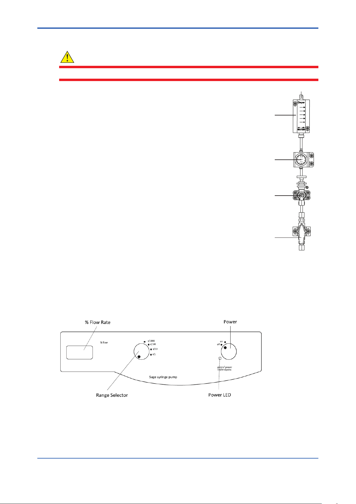
<4. Calibration>
n Rinsing the Flow Cell
WARNING
Be sure to follow the procedure for rinsing the ow cell.
1. Open the sample inlet valve, see A.
• Position the valve with the pointed end facing up for open
position.
2. Open the bypass/needle valve by turning it counterclockwise, see B.
• Check for the appropriate sample ow.
• Adjust the pressure regulator if required. See step 3.
3. Adjust the knob on the pressure regulator, see C, so the ball in the
ow meter indicates the correct ow rate reading, see D. The ow
rate should be adjusted to 40 mL/minute.
• Pull out the knob to unlock the setting and allow adjustment of
the ow rate.
• Turn the knob clockwise to increase the ow rate.
• Turn the knob counterclockwise to decrease the ow rate.
• Push in the knob to lock the setting.
4-2
D
C
B
4.2 Dynamic Calibrator Operation
The dynamic calibrator is used to deliver a standard solution to the WE430 analyzer during
calibration. Place the dynamic calibrator on a support near the analyzer. The calibrator location
should be close enough to allow easy connection of the syringe tubing to the injection port on
analyzer.
Figure 4.2
A
Figure 4.1
Fluidics Components
Dynamic Calibrator must be purchased directly from Thermo Fisher Scientic.inc.
IM 12Y18A03-01EN 1st Edition : Oct. 04, 2019-00
Page 52

<4. Calibration>
4.3 Dynamic Calibrator and Syringe Setup
1. Connect the calibration tubing to the syringe using the luer adapter and the 1/4’’ female
connector. Only hand tighten the components, do not overtighten them.
2. Loosen the blue knob on the dynamic calibrator by turning it approximately 1/4 of a turn
clockwise and pressing up on the bottom, inside part of the blue knob. Lift the blue syringe
holder and turn it away from the syringe cradle. Set the lled syringe in the center syringe
cradle. Rotate the syringe holder back in place across the syringe. Gently tighten the blue
knob by turning it 1/4 of a turn counterclockwise.
3. Lift the black drive carriage straight up. Move the carriage back and re-engage it with the
gears, leaving room for the syringe. Check the alignment of the drive carriage to ensure it is
perfectly straight.
4. Replace the drive carriage on the gears. Advance the carriage to meet the syringe by
momentarily turning the pump on high speed.
NOTE
Do no attempt to push the carriage manually. This may result in damage to the pump
mechanism.
5. Set the blue endpoint limiter midway between the white indicator marks.
4-3
4.4 Performing a DYN Calibration
• To begin a DYN calibration, the system starts from the measure mode.
• The analyzer must be set to the hydrazine application in the setup mode prior to performing
a calibration. Refer to Section 3.1, Use of the Setup Mode.
NOTE
A three-way valve can be installed upstream of the analyzer inlet to allow easy switching to a
oxygen scavenger-free sample such as demineralizer output or condensate pump discharge.
Step Operator Action Scrolling Marquee Main Display Notes
1 Make sure that the analyzer is in the
measure mode.
2
Press to initiate the calibration.
3 If the calibration password is active,
enter the calibration password by
pressing / to set the rst
digit, to move to the next digit,
/ to set the values of the
remaining digits and to move
through the remaining digits.
Press to accept the password.
4 CH1 or CH2
5
Press / to select the channel
that will be calibrated and press to
begin the calibration.
6 DYN or OFFL
7
Press / to select DYN and
press to accept the setting.
Actual temperature
reading
ENTER PASSWORD PASS
(ashing)
CH1 or CH2
(ashing)
(ashing)
DYN
(ashing)
Actual
concentration
reading
# # # #
CAL
CHnL
CAL
CHnL
CAL
tYPE
CAL
tYPE
CAL appears as
mode
Displayed for two
channel analyzer
Action required for
two channel analyzer
IM 12Y18A03-01EN 1st Edition : Oct. 04, 2019-00
Page 53
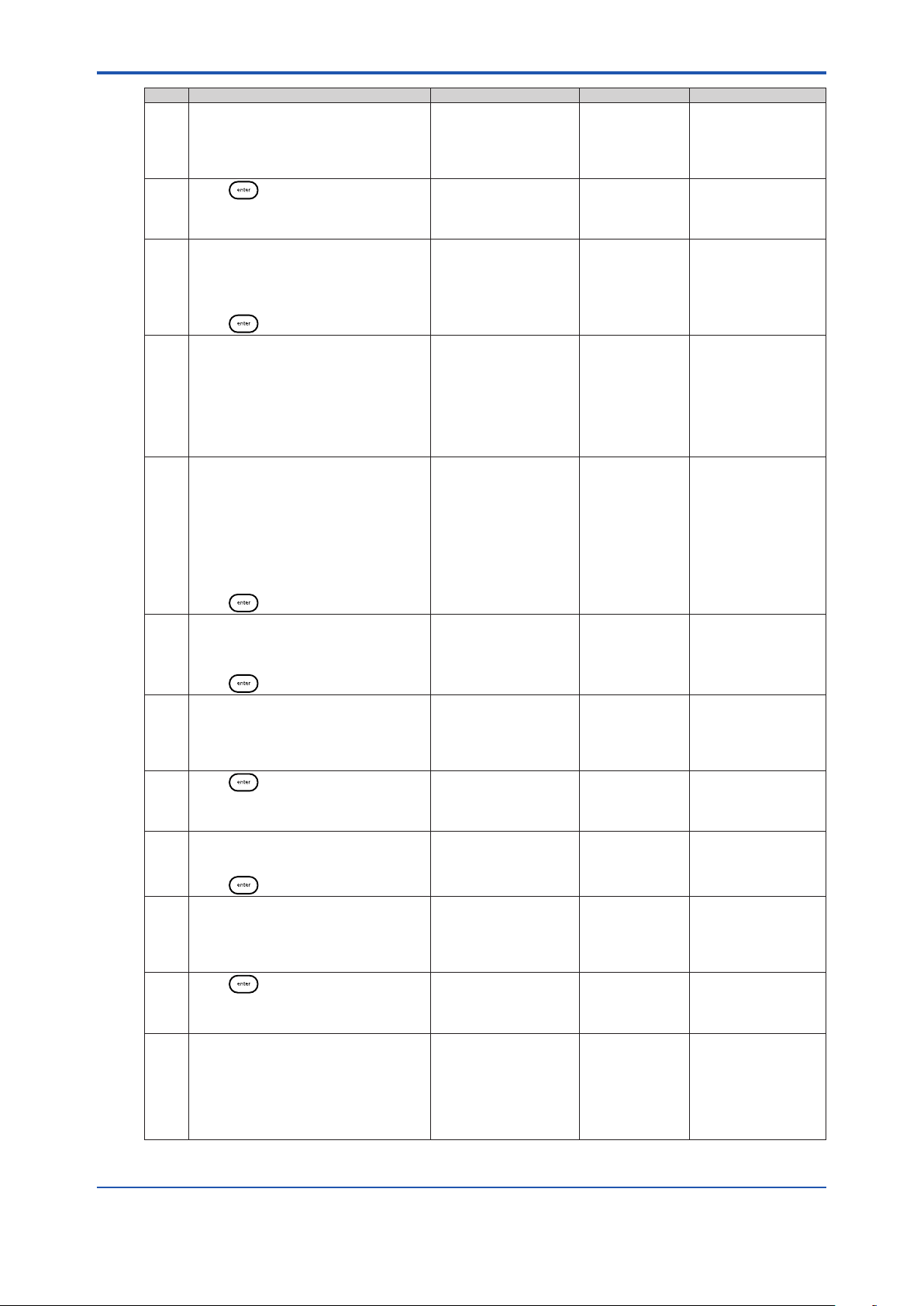
<4. Calibration>
Step Operator Action Scrolling Marquee Main Display Notes
8 Polish the iodide sensing electrode.
Connect the WE430 analyzer to an
oxygen scavenger-free sample.
Run the analyzer at 40 mL/minute for
30 minutes.
9
Press .
10 Verify that the sample ow rate is
actually 40 mL/minute. Adjust the
sample ow rate if required.
Make sure that the sample bypass
valve is o during this step.
Press .
11 Prepare a 2 ppm hydrazine standard
using the 100 ppm hydrazine standard,
Cat. No. 151810.
To prepare a 2 ppm hydrazine standard,
add 20 mL of the 100 ppm hydrazine
standard to a one liter volumetric ask
and dilute to the mark with distilled
water. Mix the solution well.
12 Fill a 20 cc syringe with the 2 ppm
standard solution. Expel any air
bubbles in the syringe.
Connect the syringe tubing to the
standard injection port.
Open the port by turning the
thumbscrew 1/4 of a turn to the right, so
the dot is aligned with the direction of
the ow.
Press .
13 Turn on the dynamic calibrator.
Turn the ow rate dial until the ow rate
reads 999 (99.9% ow).
Turn the range switch to x/100.
Press .
14 Wait 4 minutes. MEASURING STD1
15
Press .
16 Turn the ow rate dial until the ow rate
reads 525 (52.5% ow).
Turn the range switch to x/10.
Press .
17 Wait 3 minutes. MEASURING STD2
18
Press .
19 No action necessary. System calculates
POLISH IODIDE
ELECTRODE
CONNECT TO OX-SCAV FREE SAMPLE
WAIT 30 MINUTES
PRESS ENTER Actual readings
ADJUST SAMPLE
FLOW TO 40 mL/
MINUTE
PRESS ENTER
SETUP PUMP
PURGE AIR AND
CONNECT
SYRINGE TO
INJECTION PORT
OPEN VALVE
DOT TO LEFT
PRESS ENTER
SETUP PUMP
PURGE AIR AND
CONNECT
SYRINGE TO
INJECTION PORT
OPEN VALVE
DOT TO LEFT
PRESS ENTER
SET PUMP TO 999
PERCENT-FLOW AND
X1/100 RANGE
TURN PUMP ON
PRESS ENTER
WAIT 4 MINUTES
PRESS ENTER Actual readings
SET PUMP TO 525
PERCENT-FLOW AND
X1/10 RANGE
PRESS ENTER
WAIT 3 MINUTES
PRESS ENTER Actual readings
Actual readings
ashing
ashing
FLO For the best accuracy,
SEt
dYn
SEt
dYn
Std 1 The 2 ppm standard
Actual readings
ashing
ashing
Std 2 The 2 ppm standard
Actual readings
ashing
ashing
Minutes will be
counted down on the
marquee.
When 30 minutes
have elapsed, the
marquee will display
PRESS ENTER.
measure the ow
at the drain, weigh
the timed discharge
repeatedly and
average the results.
The 2 ppm standard
will produce a 20
ppb and 100 ppb
N2H4 readings on
the analyzer during
calibration.
Refer to Section 4.2,
Dynamic Calibrator
Operation for
instructions on how to
install the syringe and
set up the dynamic
calibrator.
will produce a 20 ppb
N2H4 by the sample
stream.
System circulates
sample.
Minutes will be
counted down on the
marquee.
When 4 minutes have
elapsed, the marquee
will display
PRESS ENTER.
is diluted to 100 ppb
N2H4 by the sample
stream.
System circulates
sample.
Minutes will be
counted down on the
marquee.
When 3 minutes have
elapsed, the marquee
will display
PRESS ENTER.
new E0 and slope and
checks for errors.
If there is a calibration
error, the appropriate
error message will be
displayed.
4-4
IM 12Y18A03-01EN 1st Edition : Oct. 04, 2019-00
Page 54
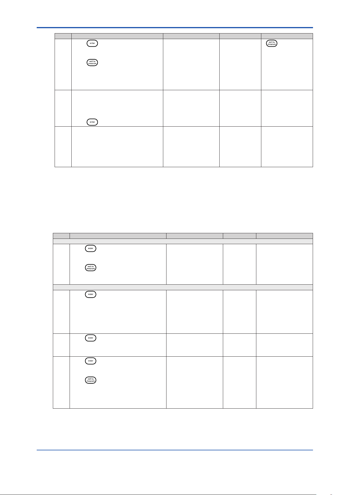
<4. Calibration>
Step Operator Action Scrolling Marquee Main Display Notes
20
Press to accept the new slope
and E0 values
or
Press to abort the calibration.
The new slope and E0 values will not
be saved. The last saved calibration
prior to the aborted calibration will be
used in the measure mode.
21 Turn o the dynamic calibrator.
Close the standard injection port by
turning the thumbscrew 1/4 of a turn to
the left, so the dot is perpendicular with
the direction of the ow.
Press .
22 System will proceed to measure mode. Actual temperature
NEW CALIBRATION
SLOPE AND E
PRESS ENTER TO
ACCEPT OR PRESS
EXIT TO ABORT
WITHOUT SAVING
TURN PUMP OFF
CLOSE INJECTION
VALVE
DOT DOWN
PRESS ENTER
reading
0
Calculated Slope
and E
0
Actual
concentration
reading
If is pressed,
refer to the Calibration
Abort Steps section.
System enters
measure mode, but
will remain on hold
until the hold timer
expires.
Default hold time is
30 minutes.
4-5
4.5 Calibration Error Codes
At any point during a calibration, the appropriate error message will be displayed if there is a
calibration related error.
The following table lists common calibration error codes with their marquee display and required
operator actions.
Step Operator Action Scrolling Marquee Main Display Notes
Stability Time Out Error
Error
Press to continue the calibration
41
despite the reading instability.
or
Press to abort the calibration and
refer to Exit 3. Repeat the calibration or
refer to the troubleshooting section.
Calibration Errors
Error
Press to abort the calibration and
42
refer to Exit 3.
Verify that the correct standards were
used during the calibration, the standard
values were entered correctly and in the
right order and the electrodes are working
properly and then repeat the calibration.
Error
Press to abort the calibration and
107
refer to Exit 3.
Error
Press to continue the calibration
109
despite the bad slope.
or
Press to abort the calibration and
refer to Exit 3.
READINGS WERE
UNSTABLE PRESS
ENTER TO CONTINUE
CALIBRATION OR
PRESS EXIT TO
ABORT
INVALID SLOPE
PRESS ENTER
CALIBRATION
DATA TOO CLOSE
TOGETHER PRESS
ENTER
CH1 BAD SLOPE
PRESS ENTER
E041 The required system
stability was not
reached and a time out
error occurred.
Perform electrode
cleaning, conditioning
and troubleshooting.
E042 The calculated slope
was invalid. Standard
values were likely
entered in the wrong
sequence or wrong
standard values were
entered.
E107 Use new standards.
Perform electrode
cleaning, conditioning
and troubleshooting.
E109 The calculated slope
was outside of the
recommended range.
Perform electrode
cleaning and
conditioning, refer to
the troubleshooting
section and repeat the
calibration.
IM 12Y18A03-01EN 1st Edition : Oct. 04, 2019-00
Page 55

<4. Calibration>
Step Operator Action Scrolling Marquee Main Display Notes
Error
Press to continue the calibration
110
despite the bad slope.
or
Press to abort the calibration and
refer to Exit 3.
Error
Press to abort the calibration and
125
refer to Exit 3.
Verify that the correct standards were
used during the calibration, the standard
values were entered correctly and in the
right order and the electrodes are working
properly and then repeat the calibration.
Error
Press to abort the calibration and
126
refer to Exit 3.
Verify that the correct standards were
used during the calibration, the standard
values were entered correctly and in the
right order and the electrodes are working
properly and then repeat the calibration.
CH2 BAD SLOPE
PRESS ENTER
CH1 BAD
OFFSETPRESS
ENTER
CH2 BAD
OFFSETPRESS
ENTER
E110 The calculated slope
was outside of the
recommended range.
Perform electrode
cleaning and
conditioning, refer to
the troubleshooting
section and repeat the
calibration.
E125 Use new standards.
Perform electrode
cleaning, conditioning
and troubleshooting.
E126 Use new buers or
standards. Perform
electrode cleaning,
conditioning and
troubleshooting.
4-6
4.6 Calibration At Custom Concentrations Using DYN
The WE430 Hydrazine analyzer software has default values to accommodate standards added
using the dynamic calibrator. The operator has the option to use alternate standards by changing,
in the setup mode, the default values.
Hydrazine Default Values
Analyzer Flow Rate = 40 mL/minute
Standard Concentration = 2 ppm
Standard 1 Percent Flow = 99.9%
Standard 1 Range = x/100
Standard 2 Percent Flow = 52.5%
Standard 2 Range = x/10
Dynamic Calibrator Settings
Settings on the dynamic calibrator are based on a 20 cc syringe at 100% (39.7 mL/minute). The
ow rate of the standard (F
the range. Refer to the dynamic calibrator user guide for additional information.
C = [(Cb • Fb) + (C
std
• F
Where:
C = Measured concentration during calibration
Cb = Background concentration (assumed to be zero)
C
= Concentration of standard in the syringe
std
Fb = Background ow rate of analyzer (approximately 40 mL/min).
F
= Flow rate of standard
std
) is the 39.7 mL/minute multiplied by the percent setting, divided by
std
)] / (Fb + F
std
std
)
IM 12Y18A03-01EN 1st Edition : Oct. 04, 2019-00
Page 56

<4. Calibration>
4.7 Dynamic Calibrator Check
1. The normal ow rate from the 20 cc syringe when the dynamic calibrator percent ow dial
is set to 500 (equals 50% ow) and when the range switch is set at x/1 is 20 mL/minute.
Therefore, the ow rate at x/10 is 2 mL/minute and at x/100 is 0.2 mL/minute.
2. Place a 10 mL graduated cylinder so that the calibration tubing will reach the top of the
cylinder.
3. Turn the pump range switch to x/100 and allow the ow to begin and to ll the tubing
completely, purging all air bubbles.
4. Simultaneously, insert the calibration tubing into the mouth of the graduated cylinder and
start a stopwatch.
5. Allow the ow to continue into cylinder for exactly ten minutes. Remove the tubing from the
cylinder and the pump o.
The total volume of the graduated cylinder should be 2.0 ± 0.1 mL.
If the total volume is not 2.0 ± 0.1 mL, the ow rate dial may be adjusted using the following
formula:
adjusted ow rate setting = present setting •
For example, if the actual total ow was 1.8 mL, the new ow rate
setting will equal = (500) • (2.0/1.8) = 555
6. Perform the same ow rate check with the range switch on x/10 using a 50 mL graduated
cylinder. Set the percent ow dial to read 500 (50.0%).
7. Allow the ow to continue into cylinder for exactly ve minutes. Remove the tubing from the
cylinder and turn the pump o.
The total volume of the graduated cylinder should be 10.0 ± 1.0 mL.
Fine adjustment of the ow rate dial may be made if the total ow is dierent from the
specied amount.
For example, if the actual total volume was 11.0 mL, the new ow rate
setting will equal = (500) (10.0/11.0) = 455
expected total volume
actual total value
4-7
NOTE
For the best possible accuracy for the dynamic calibrator check, weigh volumes delivered for use
in calculations.
4.8 Oine Calibration Procedure
The oine calibration feature is simply a one point calibration without slope change. The term
“oine calibration” refers only to the fact that a sample from WE430 bypass is taken “oine”
for laboratory analysis; in fact, no downtime is experienced and the analyzer remains online
throughout the procedure.
Step Operator Action Scrolling Marquee Main Display Notes
1 Open the bypass/needle valve to
redirect the sample ow.
2
Press to initiate the calibration.
3 If the calibration password is active,
enter the calibration password by
pressing / to set the rst
digit, to move to the next digit,
/ to set the values of the
remaining digits and to move
through the remaining digits.
Press to accept the password.
4 CH1 or CH2
Actual temperature
reading
ENTER PASSWORD PASS
(ashing)
Actual concentration
reading
# # # #
CAL CHnL Displayed for two
HOLD and CAL
appear as mode.
channel analyzer
IM 12Y18A03-01EN 1st Edition : Oct. 04, 2019-00
Page 57
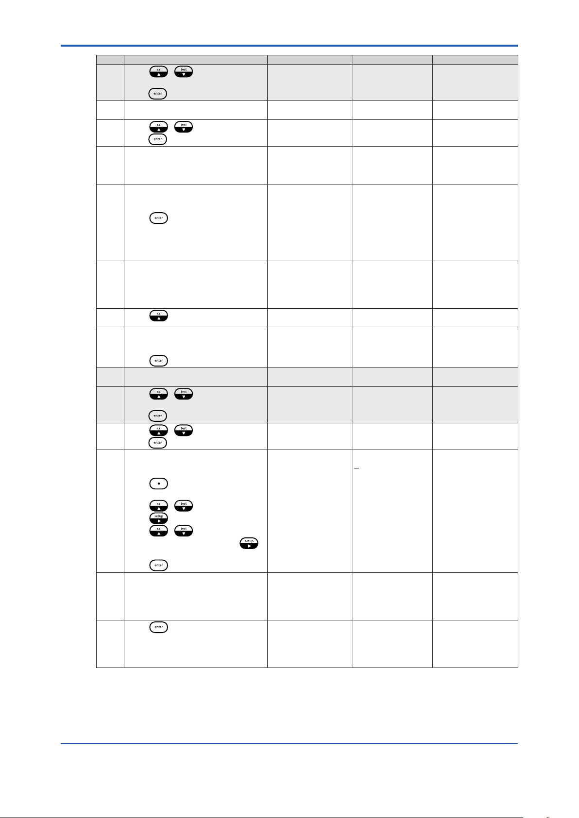
<4. Calibration>
Step Operator Action Scrolling Marquee Main Display Notes
5
Press / to select the
channel that will be calibrated and
press to begin the calibration.
6 DKA or OFFL
7
Press / to select OFFL and
press to accept the setting
8 Wait 1 to 10 minutes. MEASURING
9 Take a QC sample from the 2118XP
analyzer bypass for laboratory
analysis.
Press .
10 Perform laboratory analysis on QC
sample and return with results.
11
Press to resume the calibration.
12 If the calibration password is active,
enter the calibration password as
described in step 3.
Press to accept the password.
13 CH1 or CH2
14
Press / to select the
channel that will be calibrated and
press to begin the calibration.
15
Press / to select OFFL and
press to accept the setting.
16 Enter the concentration value of the
QC sample obtained from laboratory
analysis:
Press to move the decimal point
and set the value as ppm or ppb.
Press / to set the rst digit.
Press to move to the next digit.
Press / to set the values of
the remaining digits and press
to move through the remaining digits.
Press to save the value.
17 NEW CALIBRATION
18
Press .
CH1 or CH2
(ashing)
(ashing)
OFFL
(ashing)
SAMPLE WAIT 1
MINUTE AWAITING
DATA STABILITY
TAKE SAMPLE
FROM BYPASS
DRAIN PRESS
ENTER TO USE
METER THEN
PRESS CAL
TO ENTER LAB
RESULTS
Actual temperature
reading
ENTER PASSWORD PASS
(ashing)
CH1 or CH2
(ashing)
OFFL
(ashing)
LAB ANALYSIS
READY INPUT
CONC VALUE FROM
LAB PRESS ENTER
TO CONTINUE OR
PRESS EXIT TO
ABORT
E0 PRESS ENTER
TO ACCEPT OR
PRESS EXIT TO
ABORT
CAL CHnL Action required for
CAL tYPE
CAL tYPE
Actual readings
ashing
LAb
Actual concentration
reading
# # # #
CAL CHnL Displayed for two
CAL CHnL Action required for
CAL tYPE
COnC
# # # . #
(change ashing
digit)
Actual E0 value The system
two channel analyzer
System continuously
evaluates the
data until a stable
condition is met.
System will return to
measure mode and
operate as normal.
CAL and MEASURE
appear as mode.
HOLD and CAL
appear as mode.
channel analyzer.
two channel analyzer.
will display the
recalculated the E0.
The system willreturn
to the measure mode.
Only MEASURE
should appear as
mode.
4-8
IM 12Y18A03-01EN 1st Edition : Oct. 04, 2019-00
Page 58

<5. Analyzer Maintenance>
5. Analyzer Maintenance
5.1 Maintenance Schedule
The WE430 Hydrazine analyzer is designed for simple maintenance. Follow the instructions in
this section to ensure proper operation of your analyzer.
n Recommendations
To ensure proper maintenance and good analyzer performance, a service logbook should be
kept.
• Record maintenance date and the type of service work completed.
• Mark the date and the uid levels of the reagent and the date when it was replaced.
• Tag each electrode cable with the installation date of the electrode.
5.2 Weekly Maintenance
1. Check that the sample ow rate is 35 to 45 mL/minute. To alter the ow rate, pull out the
locking knob of the pressure regulator, then rotate the black knob to increase (clockwise) or
decrease (counterclockwise) sample ow. Push in the locking knob of the pressure regulator
to lock the ow rate.
2. Inspect the analyzer for leakage. Diusion tubing leakage is indicated by a rise in the level of
reagent.
3. Check that there are no error indications and that the current concentration level is
reasonable.
4. Check that the reference lling solution is adequate.
5. If required, wipe the analyzer with a damp cloth to remove dirt and dust particles.
5-1
5.3 Bi-Weekly Maintenance
Refer to Section 2.8, Installation of a New Reference Electrode.
n Reference Electrode Filling Solution Replacement
WARNING
Turn o the air pump prior to removing the reference electrode lling solution bottle. If the air
pump is left on, it will spatter lling solution as the bottle is removed.
The reference electrode lling solution needs to be replaced approximately every two weeks. If
the reservoir is less than one quarter full, replace the solution. This should be checked every two
weeks to ensure that the electrode does not run dry.
1. Remove the spent electrolyte bottle from the clip. Unscrew the cap and discard the bottle.
2. Remove the cap and seal from the new reference electrode lling solution. Check that the
rubber gasket is properly aligned and then connect the cap and tubing assembly to bottle.
The 1/8’’ tubing should extend into the bottle.
3. Invert the electrolyte bottle and snap it into the clip.
4. Use the special pushpin attached to the pressurized reference assembly on the analyzer to
pierce a hole in the bottom of the bottle and re-pressure the reservoir by the air pump.
5. Dry the frit at the base of the reference electrode. Check the frit to see if a bead of ll
solution forms, which indicates good electrolyte ow.
IM 12Y18A03-01EN 1st Edition : Oct. 04, 2019-00
Page 59

<5. Analyzer Maintenance>
5.4 Monthly Maintenance
Calibration frequency is operator dependent for the most accurate and precise measurements.
5.4.1 Calibration
• Replacement of the reagent requires calibration. Refer to Section 4.4, Performing a DYN
Calibration.
• Calibration intervals can be programmed using the setup mode. This will prompt the
operator to recalibrate after a specic amount of time has passed. Refer to Section 3.1, Use
of the Setup Mode.
5.4.2 Replacement of Sample Inlet Filter
1. If the sample ow can be adjusted with the pressure regulator to 50 mL/minute or more, skip
this procedure.
2. Turn o sample ow by turning the inlet valve to the right.
3. Remove the lter hex cap using a 1 inch open-ended wrench.
4. Separate the lter cap with bypass/needle valve assembly from the lter body, retaining the
ring.
5. Remove the lter element and soft gasket (if necessary).
6. Replace the gasket and press a new sintered element into the lter body.
7. Replace the hex cap and bypass/needle valve assembly and reposition the bypass drain
line into the drain assembly.
8. Retighten the hex cap to approximately 75 pound-inch in torque.
9. Turn on the sample ow by turning the inlet valve left.
10. Check for leaks.
5-2
5.4.3 Polish Iodide Electrode
Refer to Section 2.6, Installation of a New Iodide Electrode.
Polish the iodide electrode according to the instructions that are included with the polishing strips.
Rinse the electrode thoroughly with distilled water, insert the iodide electrode into its holder in the
ow cell and then plug the electrode cable marked “Sensing” into the top of the electrode.
5.4.4 Air Pump Check
The reference electrode ll solution level should drop at least 1/8’’ per month, which indicates
good ow through the electrode frit. If the ow rate is low, the air pump should be tested for
proper operation.
To test the air pump, remove the pushpin and tubing from the reference reservoir. Place the tip of
the pushpin in a beaker of water. Vigorous bubbling should be observed. Normally, the air pump
delivers at least 500 cc/minute of air. Replace the air pump if weak bubbling or no bubbling is
observed. To ensure a tight seal on the reservoir, replace it with a fresh bottle of ll solution (Cat.
No. 181073).
5.4.5 Replacement of Reagent and Diusion Tubing
Assembly
WARNING
The reagent is hazardous. Use protective glasses and gloves and work in a well-ventilated area
or a fume hood. Avoid contact with skin or clothes. In case of skin contact, ush skin immediately
with water to prevent burns. Refer to the bottle label for precautions.
IM 12Y18A03-01EN 1st Edition : Oct. 04, 2019-00
Page 60

<5. Analyzer Maintenance>
1. Support the bottom of the reagent bottle and release the holding clamp with one hand. Turn
the thumbscrew counterclockwise to release the reagent bottle. Unscrew the white bottle
cap and gray tubing connector assembly. Since the reagent contains concentrated acid,
which is very corrosive to skin and eyes, take the reagent to a well ventilated area such as a
laboratory fume hood. Wear rubber gloves and eye goggles. Unscrew the cap and pour the
old reagent into a suitable waste container.
5-3
Figure 5.1 Reagent Bottle Assembly
2. Take a new bottle of the reagent to a well ventilated area, such as a laboratory fume hood.
Unscrew and remove the white cap on the bottle.
3. Connect the diusion tubing (Part number: K9705CJ) to the tubing connector assembly.
Place the tubing assembly and cap into the bottle.
4. Replace the gray cap and screw the white cap on tightly.
5. Insert the ve nipples on the top of the reagent bottle into the uid connector block.
6. Support the bottom of the reagent bottle with one hand and tighten the thumbscrew
clockwise.
7. Clamp the bottle to the uidics panel to secure it.
IM 12Y18A03-01EN 1st Edition : Oct. 04, 2019-00
Page 61

<5. Analyzer Maintenance>
5.5 Yearly Preventive Maintenance
5.5.1 Electrodes
1. Replace the reference electrode (Part number: K9705CH). Refer to Section 2.8, Installation
of a New Reference Electrode for step-by-step instructions.
2. Replace the iodide sensing electrode (Part number: K9705CG). Refer to Section 2.6,
Installation of a New Iodide Electrode for step-by-step instructions.
3. Replace the hydrazine standard solution (Cat. No. 151810).
Dispose of all old solutions according to the SDS instruction. SDS les can be downloaded at
www.thermosher.com/water.
5.5.2 O-ring Replacement
Replace the electrode holder and micro-valve O-rings every year in addition to changing the
reagent and tubing connector assembly barb O-rings every month. Both O-rings are included in
the O-ring kit.
5.5.3 Replacement of Restrictor Tubing
Use the restrictor tube assembly. Refer to Figure 5.2 for the restrictor tubing connections.
Restrictor
tube assembly
Restrictor
adapter
5-4
Fitting
Clamp
Flow
meter
Figure 5.2 Restrictor Tubing
O-ring
To check valve
on flow cell manifold
1. Close the inlet valve to stop sample ow through the analyzer.
2. Loosen the restrictor tube tting connection from the top of the ow meter.
3. Loosen the restrictor tube tting from the left side of the ow cell block.
4. Pull out the restrictor tube assembly at each end.
5. Unscrew the clip behind ow cell that holds the restrictor tube to the panel.
6. Replace with a new restrictor tubing assembly.
7. Be sure all of the ttings are secure, to prevent leaks.
8. Open the inlet valve to start sample ow through the analyzer.
IM 12Y18A03-01EN 1st Edition : Oct. 04, 2019-00
Page 62

<6. Troubleshooting>
6. Troubleshooting
6.1 Diagnostics Mode
• From the measure mode, press to enter the diagnostics mode. The key allows
access to menus used for system diagnostics.
• Each menu is sequential. Press to scroll through the diagnostics menu selections.
• can be pressed at any time to return to the measure mode.
Default Operator Action Scrolling Marquee Main Display Notes
Diagnostics
Press while in the
measure mode to enter
the diagnostics mode.
The system will enter
the diagnostics mode
at the calibration log
menu.
Press to
stepthrough the menu
items.
CH1 CALIBRATION SLOPE AND E
CH2 CALIBRATION CELL CONSTANT
CH1 ERROR LIST PRESS VIEW
CH2 ERROR LIST PRESS VIEW
CH1 – SELECT TIME/DATE TOVIEW
MEASUREMENT LOG
CH2 – SELECT TIME/DATE TO VIEW
MEASUREMENT LOG
SELECT TIME/DATE TO VIEW STATUS LOG
SOFTWARE REV NUMBER
CH1 SERIAL NUMBER
CH2 SERIAL NUMBER
CH1 MODEL NUMBER
CH2 MODEL NUMBER
CH1 MEASURE mV AND NOISE
CH2 MEASURE mV AND NOISE
CH1 mA1 and mA2 OUTPUT VALUES
SENSOR/TEMP
CH2 mA1 and mA2 OUTPUT VALUES
PRESS ENTER FOR THE DISPLAY TEST
PRESS ENTER TO CONTINUE
PRESS ENTER TO CONTINUE
KEYPAD TEST PRESS ALL KEYS ONE AT A
TIME
0
The display
will change
with each
menu.
6-1
If only one board
is installed in the
analyzer, only
one menu option
will be shown
in the scrolling
marquee instead
of CH1 and CH2
menu options.
6.1.1 Calibration Log
• Displays up to the last twelve calibrations using three screens:
1. Slope and E0 (analyzers with a pH module or ISE module installed), mV oset
(analyzers with an ORP module installed) or cell constant (analyzers with a
conductivity module installed)
2. Date and Time
3. Temperature
• Press to scroll between the three information screens for each calibration
• Press / to view the last twelve calibrations
Default Operator Action Scrolling Marquee Main Display Notes
Calibration Log
Press while in the measure
mode to enter the diagnostics mode
Press to display the calibration
time and date
CALIBRATION
SLOPE AND E
or
CALIBRATION
OFFSET
or
CALIBRATION CELL
CONSTANT
CALIBRATION
TIME/DATE
# # . # (Slope)
# # . # (E0)
0
# # # . # (mV oset)
# . # # # (Cell
Constant)
HH:MM
MM/DD or DD/MM
Press / to
scroll through the last
12 calibrations
IM 12Y18A03-01EN 1st Edition : Oct. 04, 2019-00
Page 63

<6. Troubleshooting>
6-2
Default Operator Action Scrolling Marquee Main Display Notes
Press to display the calibration
temperature and electrode
response
Press to proceed to the next
menu
6.1.2 Error List
• Displays a list of system events, warnings, and error codes that cause the yellow or red LED
to light.
• The top line of the main display shows the error code and the bottom line shows the number
of error codes (1-5 indicates that one of ve error codes is being displayed).
• Press / to scroll through the error list.
• Press to display a description of each error code on the marquee.
Default Operator Action Scrolling Marquee Main Display Notes
Error List
Press to display the description
of the error code on the marquee
Press / to scroll through
the error list
Press to proceed to the next
menu
CALIBRATION
TEMP
ERROR LIST
PRESS VIEW
Actual description of error code E###
Actual description of error code E###
# # . # c
(Temperature)
E###
# - #
# - #
# - #
Press / to
scroll through the last
12 calibrations
6.1.3 Measurement Log
• Displays logged measurements according to log interval entered in setup mode.
• Press to toggle between the measurement value and the data and time.
• Press / to scroll through the log entries.
Default Operator Action Scrolling Marquee Main Display Notes
Measurement Log
Press / to scroll through
the log entries
Press to scroll between the
measurement log and the data and
time display
Press to proceed to the next
menu
SELECT TIME/DATE TO VIEW
MEASUREMENT LOG
SELECT TIME/DATE TO VIEW
MEASUREMENT LOG
Actual temperature value for
logged measurement
HH:MM
MM/DD or DD/MM
HH:MM
MM/DD or DD/MM
Concentration and
mV values for logged
measurement
IM 12Y18A03-01EN 1st Edition : Oct. 04, 2019-00
Page 64

<6. Troubleshooting>
6.1.4 Status Log
• Displays a list of system events.
• Press / to scroll through the log entries.
• Press to toggle between the log code and the data and time.
6.1.5 Software Revision
• Displays the software revision numbers of the two processors.
Default Operator Action Scrolling Marquee Main Display Notes
Status Log
Press / to scroll through the
log entries
Press to scroll between the log
code and the data and time
Press to proceed to the next menu
Software Revision
Press to proceed to the next menu
SELECT TIME/DATE TO
VIEW STATUS LOG
SELECT TIME/DATE TO
VIEW STATUS LOG
PRESS UP/DOWN KEY TO
VIEW STATUS LOG
SOFTWARE REV NUMBER r # . # #
HH:MM
MM/DD or DD/MM
HH:MM
MM/DD or DD/MM
Event Code
r # . # #
6-3
6.1.6 Electronics Serial Number
• Displays the serial number of the electronics assembly.
6.1.7 mV and Noise Measurements
• Displays the current mV measurement value and the noise associated with the
measurement.
6.1.8 mA Output Values
• Displays current mA values for mA1 and mA2 outputs.
Default Operator Action Scrolling Marquee Main Display Notes
Electronics Serial Number
SERIAL NUMBER # # #
Press to proceed to the next menu
Model Number
MODEL NUMBER # # # #
Press to proceed to the next menu
mV and Noise Measurements
MEASURE mV AND
NOISE
Press to proceed to the next menu
mA Output Values
mA OUTPUT VALUES
mA1/ mA2
Press to proceed to the next menu
# # #
# # # #
Current mV
measurement and noise
Current mA output
values for mA1 and mA2
6.1.9 Display Test
• Press to start display test.
1. All the display segments will light up and the system will cycle through the LED colors.
2. Verify that all the display segments are on and that the LED colors are functional and press
.
IM 12Y18A03-01EN 1st Edition : Oct. 04, 2019-00
Page 65
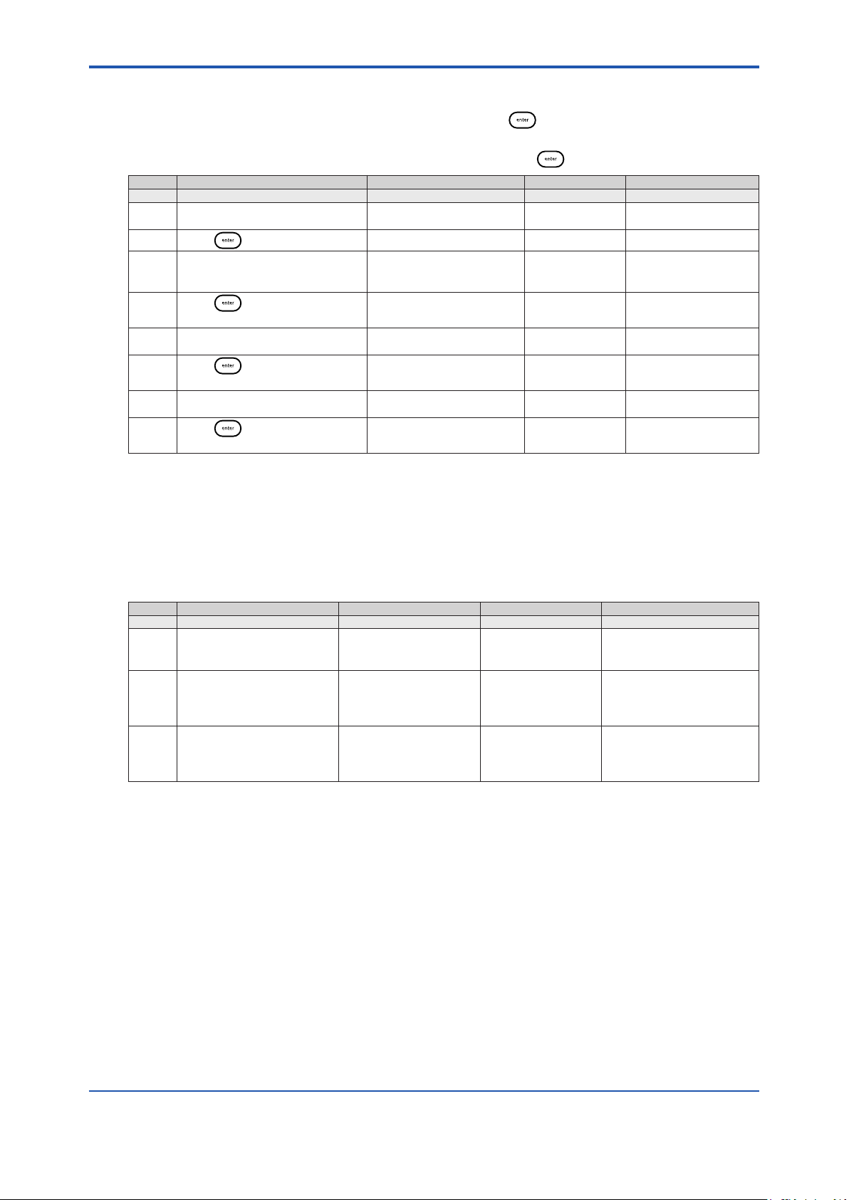
<6. Troubleshooting>
3. All the display segments will turn o except for the marquee display, which should show
PRESS ENTER TO CONTINUE.
4. Verify that all the display segments are o and press .
5. The system will show a counting number pattern on both lines of the main display.
6. Verify that the display segments are functional and press to proceed to the keypad test.
Default Operator Action Scrolling Marquee Main Display Notes
Display Test
Press to start the test
Verify that all of the display
segments are on and that the
LED colors are functional
Press to proceed to the next
part of the test
Verify that all of the display
segments are o
Press to proceed to the next
part of the test
Verify that all of the numeric
display segments are functional
Press to proceed to the next
menu
PRESS ENTER FOR THE
DISPLAY TEST
All segments on All segments on System will cycle
PRESS ENTER TO
CONTINUE
PRESS ENTER TO
CONTINUE
dISP
tESt
through the LED colors
All segments o
Count pattern
Count pattern
6-4
6.1.10 Keypad Test
• The main display will show 0 and the marquee will display KEYPAD TEST PRESS ALL
KEYS ONE AT A TIME.
• Press all eight keys one at a time in any order.
* After the rst key is pressed Error E033 will be displayed if a new key is not pressed within
10 seconds.
Default Operator Action Scrolling Marquee Main Display Notes
Keypad Test
Press all keys one at a time
in any order
No operator action needed
The system will enter the
measure mode if the keypad
test is passed
KEYPAD TEST
PRESS ALL KEYS ONE
AT A TIME
KEYPAD TEST
PRESS ALL KEYS ONE
AT A TIME
0
Display will show
numbers 1 through 8
as keys are pressed
After the rst key is pressed
error E033 will be displayed
if a new key is not pressed
within 10 seconds
IM 12Y18A03-01EN 1st Edition : Oct. 04, 2019-00
Page 66

<6. Troubleshooting>
6.2 Slope Problems
6.2.1 Low Slope
Slope less than -40 mV/decade
• Check the electrode function, clean the electrode, recalibrate the analyzer, and if the
analyzer continues to read low, replace the electrode.
• An oxygen scavenger-free sample must be used for calibration.
• Check electronics to read mV input correctly. Use electronic test kit procedure for checking
electronics function.
Ion-selective electrodes (ISE) can be shown as DC-voltage sources with 50 to 1000 Megohm; a
very high output impedance. ISEs respond to ion concentration changes with a voltage change
of approximately -59 mV/decade for monovalent anions such as iodide. Knowing electrode and
analyzers parameters like oset potential, slope, etc allows testing of various instruments by
applying a known mV voltage.
Input Signal Expected Reading: ± (0.5 mV + 0.1%)
0 mV - 0.5 mV to + 0.5 mV
- 1000 mV -1001.5 mV to – 998.5 mV
+ 1000 mV + 998.5 mV to + 1001.5 mV
• Standards contaminated or incorrectly made – verify calibration with fresh standards.
• Standard 1 and standard 2 values not set correctly – check the percent ow rate setting and
range setting on the dynamic calibrator and in the setup mode of the analyzer. If using a
custom standard, verify the values for the dynamic calibrator.
• Standard 1 and standard 2 added in wrong sequence – check the sequence of the
standards and repeat the calibration.
• pH adjustment is not correct – check the level and ow of the reagent. Replace the reagent
if it is contaminated or the level is less than 50 mL. Refer to Section 2.4, Installation of
Reagent and Diusion Tubing.
6-5
6.2.2 High Slope
Slope greater than -75 mV/decade
• Improper calibration technique – refer to Section 4.4, Performing a DYN Calibration.
• Calibration standards contaminated – repeat the calibration using fresh standards.
• Electronics failure – reset the analyzer. Refer to Section 6.4, Resetting the Analyzer.
• Improper dynamic calibrator settings – refer to Section 4.4, Performing a DYN Calibration.
• An oxygen scavenger-free sample must be used for calibration.
• Cables interchanged – verify wiring of cable connections to terminal strip. Refer to Section
2.3, Wiring the Analyzer.
• Check the connection of the cable markers for the corresponding electrode. Cable markers
are the white tape at the cap connector on the cable.
• “Ref” for the reference electrode.
• “Sensing” for the iodide electrode.
• Sensing electrode coated – clean or replace the sensing electrode.
IM 12Y18A03-01EN 1st Edition : Oct. 04, 2019-00
Page 67

<6. Troubleshooting>
6.2.3 Troubleshooting Matrix
Malfunction Possible Cause Remedy
Noisy Blocked junction on reference electrode Make sure electrolyte is owing properly and the
Iodide or reference electrode failure Check the cable connections and location of
Temperature probe failure Disconnect ATC. Temperature should read 25 °C
Air pump failure Check the air ow for a steady stream of bubbles
Calibration standard carryover Disconnect the air pump intake tube. Rinse the
Faulty electrode cables Replace electrode cables.
Excessive Drift Sample concentration varying Check sample status. Perform a span check and
Blocked junction on reference electrode Make sure electrolyte is owing properly and the
Iodide or reference electrode failure Check the cable connections and location of
Reference electrode lling solution
empty or incorrect solution used
Diusion tubing burst Observe the liquid level in the reagent bottle. If
Temperature probe failure Disconnect ATC. Temperature should read 25 °C
Temperature probe failure Disconnect ATC. Temperature should read 25 °C
Low Flow Rate Sample pressure below 8 psi Check the sample pressure. If it is less than 8 psi,
Pressure regulator set too low Increase the pressure by pulling on the red
Inlet lter clogged Replace or clean the lter.
Restrictor tubing crimped or clogged Replace the restrictor tubing. Refer to Chapter 2.
No Air Bubbles Air line crimped or disconnected Check the air line and repair as required.
Air pump failure Replace if necessary.
Does Not
Calibrate Properly
High Readings Analyzer out of calibration Recalibrate the analyzer. Refer to Chapter 4.
Contaminated standard or syringe Use new standard solutions. Replace the syringe.
Sample used for calibration contains an
oxygen scavenger.
Temperature probe failure Disconnect ATC. Temperature should read 25 °C
Dynamic calibrator technique error Use the correct techniques. Refer to the Chapter
Reagent diluted or contaminated Replace the reagent. Refer to Chapter 2.
Flow cell contaminated Rinse the ow cell with deionized water. Flush the
Electronics failure or bad setup Reset the analyzer. Refer to Chapter 6.
Electronics failure or bad setup Reset the analyzer. Refer to Chapter 4.
Flow cell contaminated Rinse the ow cell with deionized water. Flush the
Inlet lter just replaced Flush the analyzer for one hour. Refer to Chapter
Reagent spent or diluted Replace the reagent. Refer to Chapter 2.
bottle is pressurized by the air pump.
wiring to terminal strip. Refer to Chapter 2.
(E101). Replace if necessary.
and replace if necessary.
ow cell and electrodes with deionized water by
lifting the ow cell cap. Reconnect the air pump.
if span check passes, the analyzer is okay.
bottle is pressurized by the air pump.
wiring to terminal strip. Refer to Chapter 2.
Use Cat. No. 181073 reference electrode lling
solution.
the liquid level rises, replace the reagent and
diusion tubing. The tubing connector may need
replacement. Refer to Chapter 2.
(E101). Replace if necessary.
(E101). Replace if necessary.
increase the pressure. Refer to Chapter 2.
locking ring and turning the black knob clockwise.
Refer to Chapter 2.
Oxygen scavenger-free sample must be used for
calibration. Refer to Chapter 4.
(E101). Replace if necessary.
4.
ow cell overnight at calibration liquid level. Refer
to Chapter 4.
ow cell overnight at calibration liquid level. Refer
to Chapter 4.
4. If an oine calibration was performed, verify
accuracy of alternate method value. Refer to
Chapter 4.
6-6
IM 12Y18A03-01EN 1st Edition : Oct. 04, 2019-00
Page 68

<6. Troubleshooting>
Malfunction Possible Cause Remedy
Over-Range
Readings
Low Readings Analyzer out of calibration Recalibrate the analyzer. Refer to Chapter 4.
Default Battery failure Consult Response Center.
Electrode connections loose or bad Verify the electrode connections to the electrode
cables.
Electrode wiring Electrodes not properly wired to terminal strip.
Refer to Chapter 2.
Blocked junction on reference electrode Make sure electrolyte is owing properly and the
bottle is pressurized by the air pump..
Iodide or reference electrode failure Electrode is shorted, cracked or damaged. Install
a new electrode. Refer to Chapter 2.
Electronics failure or bad setup Reset the analyzer. Refer to Chapter 6.
Analyzer out of calibration Recalibrate the analyzer. Refer to Chapter 4.
Sample is very pure Check sample status. Perform a span check and
if span check passes, the analyzer is okay.
Electronics failure Try resetting the analyzer. Refer to Chapter 6 or
consult Response Center.
Electronics failure Reset the analyzer. Refer to Chapter 6.
6.3 Error/Event Codes
Error/event codes will be in the format “E###”. Some of these are errors, some are warnings, and
some are purely informational. The rst digits identify the type of error or event as identied in the
table below.
6-7
Displayed
Event Code
System Status Codes
A711 ALARM1 CH1 ON Alarm 1 channel 1 engaged (closed)
A712 ALARM2 CH1 ON Alarm 2 channel 1 engaged (closed)
A713 ALARM3 CH1 ON Alarm 3 channel 1 engaged (open)
A714 AIR PUMP ON Air pump engaged
A721 ALARM1 CH2 ON Alarm 1 channel 2 engaged (closed)
A722 ALARM2 CH2 ON Alarm 2 channel 2 engaged (closed)
A723 ALARM3 CH2 ON Alarm 3 channel 2 engaged (open)
A811 ALARM1 CH1 OFF Alarm 1 channel 1 disengaged (open)
A812 ALARM2 CH1 OFF Alarm 2 channel 1 disengaged (open)
A813 ALARM3 CH1 OFF Alarm 3 channel 1 disengaged
A814 AIR PUMP OFF Air pump disengaged
A821 ALARM1 CH2 OFF Alarm 1 channel 2 disengaged (open)
A822 ALARM2 CH2 OFF Alarm 2 channel 2 disengaged (open)
A823 ALARM3 CH2 OFF Alarm 3 channel 2 disengaged
C500 CAL MODE Calibration mode entered
R400 MEAS MODE Measure mode entered
S600 SETUP MODE Setup mode entered
E028 POWER FAIL Brown out or power failure and
E033 KEYPAD FAILURE User did not press the keys during
E034 CAL PASS
E035 SYSTEM PASS
E036 USER VALUE
Description Cause Troubleshooting
(closed)
(closed)
system has stopped processing
a diagnostic mode keypad test or
keypad broken
INCORRECT
INCORRECT
INCORRECT
User entered incorrect calibration
password
User entered incorrect system
password
User entered a value that is out of
range
Verify custom settings
Repeat diagnostic mode keypad test
Verify password
Verify password
Verify value and re-enter
IM 12Y18A03-01EN 1st Edition : Oct. 04, 2019-00
Page 69

<6. Troubleshooting>
6-8
Displayed
Event Code
E037 POWER RETURN System started processing after
E040 BLANK INCORRECT Blank greater than 1ppb Verify scrolled blank value is correct.
E041 CALIBRATION
E042 INVALID SLOPE Invalid slope obtained during
System Event/Error Codes - Yellow LED
E004 DEFAULT VALUES Analyzer has been reset or is new out
E021 HARDWARE FAULT System error Contact Response Center
E101 CH1 TEMP OUT OF
E102 CH2 TEMP OUT OF
E111 CH1 CAL DUE User calibration required on channel
E112 CH2 CAL DUE User calibration required on channel
E127 CH1 mA1 OVER
E128 CH1 mA1 UNDER
E129 CH1 mA2 OVER
E130 CH1 mA2 UNDER
E131 CH2 mA1 OVER
E132 CH2 mA1 UNDER
E133 CH2 mA2 OVER
E134 CH2 mA2 UNDER
System Error Codes - Red LED
E001 HARDWARE FAULT System error Contact Response Center
E002 HARDWARE FAULT System error Contact Response Center
E018 HARDWARE FAULT System error Contact Response Center
E019 HARDWARE FAULT System error Contact Response Center
E020 HARDWARE FAULT System error Contact Response Center
E024 HARDWARE FAULT System error Contact Response Center
E026 HARDWARE FAULT System error Contact Response Center
E027 HARDWARE FAULT System error Contact Response Center
E029 HARDWARE FAULT System error Contact Response Center
E030 HARDWARE FAULT System error Contact Response Center
E038 HARDWARE FAULT System error Contact Response Center
E103 CH1 MEAS OVER
E104 CH2 MEAS OVER
Description Cause Troubleshooting
Verify custom settings
The system code may be due to out
of range measurements or an invalid
previous calibration
Check electrodes, electrode cables
and connectors for defects or shorts.
Replace electrodes, if necessary.
Recalibrate using new standards in
the correct calibration sequence.
Calibrate the analyzer
Check ATC cable and probe
connections. Replace if needed.
Check ATC cable and probe
connections. Replace if needed.
Recalibrate the analyzer.
Recalibrate the analyzer.
Verify user selectable mA1 high limit
value in setup mode.
Verify user selectable mA1 low limit
value in setup mode.
Verify user selectable mA2 high limit
value in setup mode.
Verify user selectable mA2 low limit
value in setup mode.
Verify user selectable mA1 high limit
value in setup mode.
Verify user selectable mA1 low limit
value in setup mode.
Verify user selectable mA2 high limit
value in setup mode.
Verify user selectable mA2 low limit
value in setup mode.
Check if electrode is not connected,
electrode cables are faulty or
electrode junction is fouled
Check if electrode is not connected,
electrode cables are faulty or
electrode junction is fouled
TIMEOUT
RANGE
RANGE
RANGE
RANGE
RANGE
RANGE
RANGE
RANGE
RANGE
RANGE
RANGE
RANGE
brown out or power failure
The electrode has not reach stability
within the specied time
calibration
of box
Temperature sensor on channel 1 out
of range (5 °C to 45 °C) for ISE
Temperature sensor on channel 2 out
of range (5 °C to 45 °C) for ISE
1. No calibration has been performed
in user specied time interval.
2. No calibration has been performed
in user specied time interval.
Measured sensor value above mA1
high limit value on channel 1
Measured sensor value below mA1
low limit value on channel 1
Measured temperature value above
mA2 high limit value on channel 1
Measured temperature value below
mA2 low limit value on channel 1
Measured sensor value above mA1
high limit value on channel 2
Measured sensor value below mA1
low limit value on channel 2
Measured temperature value above
mA2 high limit value on channel 2
Measured temperature value below
mA2 low limit value on channel 2
Measurement is over range on
channel 1, the display should also be
ashing ‘9999’
Measurement is over range on
channel 2, the display should also be
ashing ‘9999’
IM 12Y18A03-01EN 1st Edition : Oct. 04, 2019-00
Page 70

<6. Troubleshooting>
6-9
Displayed
Event Code
E109 CH1 BAD SLOPE Last calibration produced a bad slope
E110 CH2 BAD SLOPE Last calibration produced a bad slope
E113 CH1 CAL OVERDUE Calibration is overdue on channel
E113 CH2 CAL OVERDUE Calibration is overdue on channel
E121 CH1 TEMP BROKEN Temperature sensor on channel 1
E122 CH2 TEMP BROKEN Temperature sensor on channel 2
E125 CH1 BAD OFFSET Last calibration produced a bad E0
E126 CH2 BAD OFFSET Last calibration produced a bad E0
Description Cause Troubleshooting
on channel 1. Slope is less than -40
mV/decade or more than -75 mV/
decade or the calibration standards
may have been interchanged.
on channel 2. Slope is less than -40
mV/decade or more than -75 mV/
decade or the calibration standards
may have been interchanged.
1 by more than 50% of the user
specied time interval
2 by more than 50% of the user
specied time interval
broken or out of range
broken or out of range
oset on channel 1
oset on channel 2
Recalibrate the analyzer using fresh
standards. Recalibrate using the
correct sequence of standards.
Recalibrate the analyzer using fresh
standards. Recalibrate using the
correct sequence of standards.
Recalibrate the analyzer
Recalibrate the analyzer
Check ATC cable connections and
probe for damage. Replace if needed.
Check ATC cable connections and
probe for damage. Replace if needed.
Recalibrate the analyzer using
fresh standards. Check electrode
connections. Replace electrode, if
needed.
Recalibrate the analyzer using
fresh standards. Check electrode
connections. Replace electrode, if
needed.
6.4 Resetting the Analyzer
The WE430 Hydrazine analyzer allows the user to reset the analyzer through the setup mode or
by a hard reset. Resetting the analyzer will restore all settings in the setup mode to factory default
values.
WARNING
Resetting the analyzer will erase all data logs including calibration, and password protection
settings for setup and calibration.
The analyzer will reset setup parameters to factory default settings.
Operator Action Scrolling Marquee Main Display Notes
Press in the measure modeto enter the
setup mode
Last menu used in setup
mode
Press / until RSET appears in the
marquee
RSET
(ashing)
Press to reset the analyzer
PRESS TEST
VIEWENTER TO RESET
SEL
SCrn
SEL
SCrn
rSEt
?
SETUP appears as
mode
IM 12Y18A03-01EN 1st Edition : Oct. 04, 2019-00
Page 71

<6. Troubleshooting>
6-10
Operator Action Scrolling Marquee Main Display Notes
Press
Press
Press
When the reset is complete, the system will
return to the measure mode. The operator will
need to re-enter the setup mode to continue
programming the setup parameters. Press
to returnto the setup mode.
PRESS TEST
VIEWENTER TO RESET
rSEt
?
6.4.1 Hard Reset
A hard reset should be performed if the analyzer becomes unresponsive or the status indicators
are ashing. Perform the following sequence:
• Carefully open the front cover of the electronics case (loosen the four corner screws).
• Press the small button located on the raised portion of the PCB to reset the electronics.
• Close the front cover of the electronics case and tighten the screws.
System settings and calibrations are preserved and analyzer returns to the measure mode. The
actual value for concentration and temperature will be displayed if the electrodes are properly
installed.
6.4.2 Serial Number and Software Revision
In the event you require technical assistance, please have the serial number available when
calling for assistance along with the software version.
• The analyzer serial number is located on the outside of enclosure.
• The software revision is accessed through the diagnostics mode.
This command resets
all previously set
parameters to factory
default values. Use this
command only to set
the analyzer to original
factory setup values.
IM 12Y18A03-01EN 1st Edition : Oct. 04, 2019-00
Page 72

Revision Record
l Manual Title : Model WE430 Hydrazine Analyzer
l Manual No. : IM 12Y18A03-01EN
Oct. 2019/1st Edition
Newly published
i
Yokogawa Electric Corporation
2-9-32 Nakacho, Musashino-shi, Tokyo 180-8750, JAPAN
http://www.yokogawa.com/
IM 12Y18A03-01EN 1st Edition : Oct. 04, 2019-00
Page 73

Blank Page
 Loading...