

Page 1
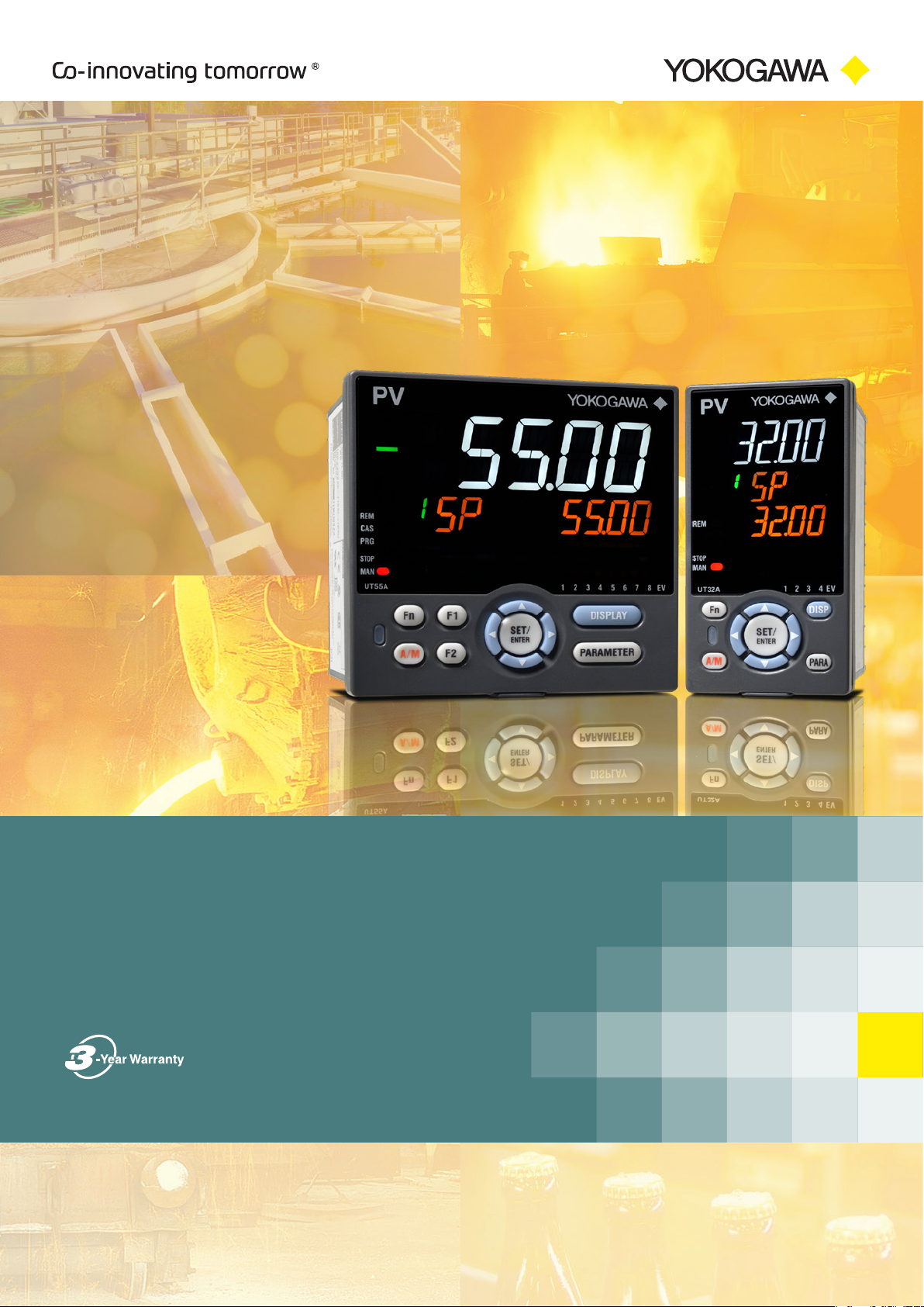
Digital Indicating Controller
UTAdvanced
Digital Indicating Controller UT75A / UT55A / UT52A / UT35A / UT32A
Program Controller UP55A / UP35A / UP32A
Digital Indicator with Alarms UM33A
Bulletin 05P01A02-01EN
Page 2
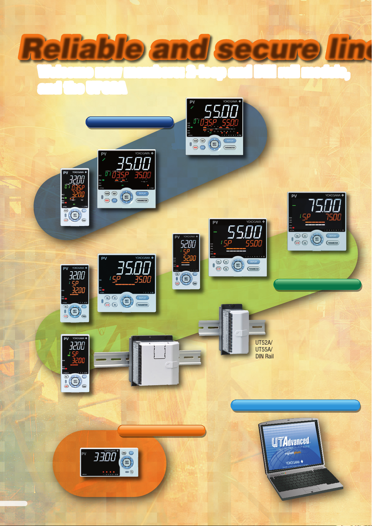
Reliable and secure lineupReliable and secure lineup
Welcome new members: 2-loop and DIN rail models,
Welcome new members: 2-loop and DIN rail models,
and the UP32A
and the UP32A
Program Controller
UP35A
UP32A
UP55A
UT75A
UT55A
UT52A
UT32A-D
(Dual-loop type)
UT35A
UT32A
Digital Controller
UT52A/MDL
UT55A/MDL
DIN Rail Mounting Controller
UT32A/MDL
UT35A/MDL
DIN Rail Mounting Controller
Conguration and Programming Software
LL50A
UM33A
Digital Indicator with Alarms
2
Page 3
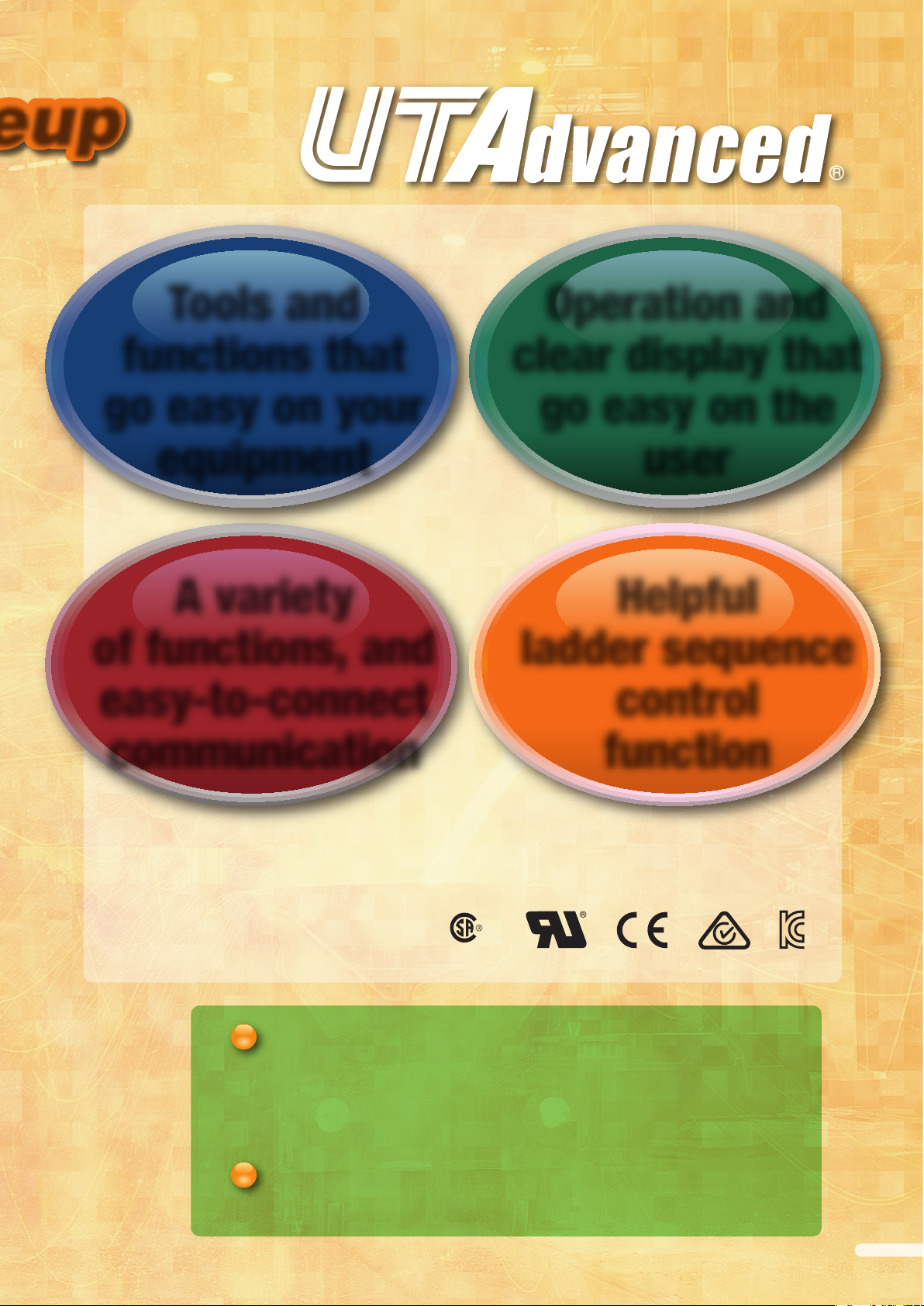
Tools and
Operation and
functions that
go easy on your
equipment
A variety
of functions, and
easy-to-connect
communication
clear display that
go easy on the
user
Helpful
ladder sequence
control
function
Reliability
Space saving options
More UP55A program patterns
• RoHS/WEEE
• NEMA4*/IP66 Front Panel
172608
CSA C22.2 61010-1
• 1/8th DIN 2-loop controller (UT32A-D)
• CC-Link communication available in a 48 x 96 mm (1/8 DIN) size
• 1/8th DIN Program controller (UP32A)
• DIN rail mounting controller (/MDL option)
• 99 program patterns (/AP option)
UL61010-1
* Hose down test only.
3
Page 4
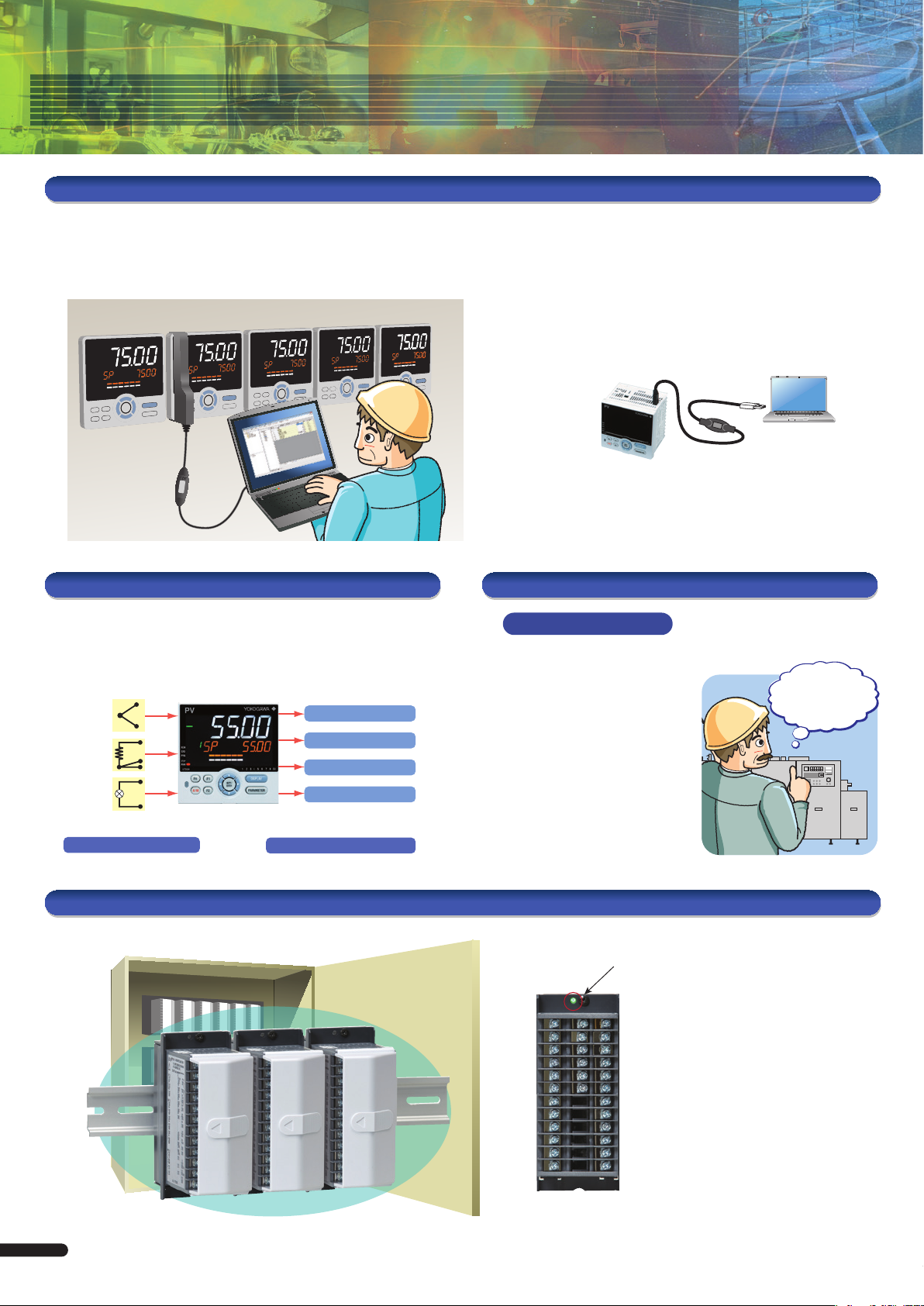
Tools and functions that go easy on your equipment
Setting and managing parameters
Easily edit settings from a PC while the unit is mounted on the controller board.
Settings are accessed through a dedicated adapter on the front panel.
Maintenance of Ethernet-equipped controllers can be handled remotely.
Control board
Optical
communication
adapter and
dedicated cable
(Light loaderTM)
To USB port
(Powered)
Can be supported with a single spare unit
Universal Input and Output
Supports different sensors, heaters,
and actuators
TC
mV
V
mA
RTD
2-wire
transmitter
Universal Inputs
4 to 20 mA current
Voltage pulse
Relay contact
Motor operated valve*
*Select a position proportional model
for motorized valve control output.
Universal Control Outputs
• Set up parameters
• Controller data read/write/compare
• Data management
• Print parameters and data, and create reports
• Congure user defaults
Set up right out of the box
To USB port
No power cable
required
Dedicated cable
With DIN rail mountable controllers (/MDL option), used to perform
maintenance when powered.
Free software now available on the web for converting GREEN series
parameters to UTAdvanced.
LL50A Parameter
Setting Software
Gets you back home. Fast.
Shorter recovery time
User defaults function
The LL50A lets you congure
user default values.
Ever get lost in a maze of
conguration changes? Now you
can restore user-personalized
default parameters. Recover
quickly without disturbing
operations.
Easily
restored by
key operation
Save space on the panel and control board
Side-by-side close mounting on DIN rails in the board
DIN rail
4
Status display (LED)
Green:Normal
Red: Abnormal
• Ambient temperature: -10 to 50 °C
(0 to 50 °C with CC-Link installed)
• 2-loop control in a single unit
(UT32A-D/MDL)
• Displays controller and I/O status
UT32A/MDL
UT52A/MDL
UT32A-D/MDL
Page 5
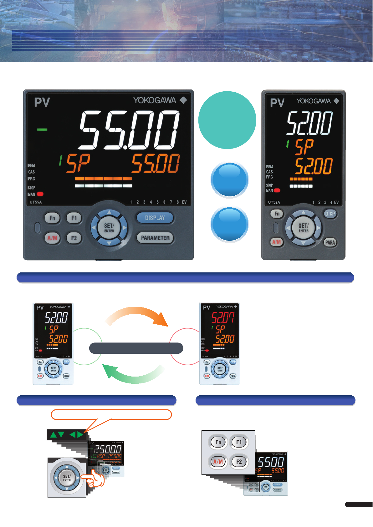
Operation and clear display that go easy on the user
Bright & Easy to Read Active Color LCD Display
Full
size
PV display
(text height: 21.55 mm)
5
digit
display
14
segment
display
UT55A 1/4 DIN (96×96mm)size UT52A 1/8 DIN (48×96mm)size
Active Color PV Display
See the status of your process conditions INSTANTLY!
• Alarms
Normal Alarm
Navigation guides and keys make it easy to operate Fast one-touch operations
Controller will guide the key you press.
Navigation Guide
According to…
Display color changes!
Programmable Function Keys
• Deviation values
• Measured values
• Contact input
• Choice of xed white or red
You can assign frequently used operations
(start/stop, remote/local, etc.) and
parameter entry screens (PID value, etc.)
to function keys for one-touch availability.
Navigation Keys
Move freely (up/down/left/right)
between parameters!
UT series
5
Page 6
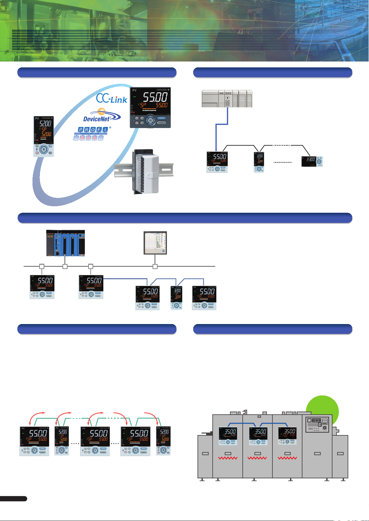
A variety of functions, and easy-to-connect communication
Communication protocol
Connect to PLCs
easily without
programming!
Modbus/TCP
Modbus
RTU/ASCII
Ladder communication
PC-Link
FA-M3V
PLC
Modbus/TCP
SMARTDAC+
GX10/GX20
Ethernet
Open Network
PLC
• Recipe management
• Remote monitoring
DeviceNet
UTAdvanced with RS-485 communication
Space-saving built-in CC-Link models
• UT52A, UT32A, UM33A, UT52A/MDL, UT32A/MDL
Modbus TCP, a protocol that allows the controller to
connect to Ethernet network and have the ability to
exchange data with the computers or devices on that
network.
You can easily set setpoints (SP),
PID, and alarms from a PLC.
Modbus slaveSerial gateway function
Ethernet-serial Gateway Function
UTAdvanced with RS-485 communication
Peer to Peer
The use of the ladder sequence program makes it possible to exchange
analog data and status data between communication-capable UTs.
Example: A UT in which an input error occurs sends a signal to another UT
to enable that UT switch to MAN operation, thus shifting the whole system
into a safe mode. In such a case, the safety mechanism can be built into
the UTAdvanced and is not required in the host system.
* Create ladder sequence programs by the LL50A Parameter Setting software (sold separately).
RS485
RS-485
• Gateway function allows RS-485 Modbus
devices to communicate via Ethernet.
• Physical layer: 10 BASE-T/100 BASE-TX
• Max. number of connection : 2
Coordinated operation
Coordinated operation: This function syncs operation of the slave with that
of the master through Yokogawa's proprietary communication protocol.
• Finely adjust the temperature setting of the slave
with the bias and ratio
• Upstream PLC or other device not needed for tuning
• No programming means fewer engineering manhours
Continuous
furnace
RS-485
Slave UT35A
Slave UT35A Master UP35A
1 2 4 15 32
Up to 4 master units, total 32 units
6
Zone 3
SP is zone 1
SP minus 5 °C
Zone 2
SP is zone 1
SP plus 10 °C
Zone 1
SP is programmed
Page 7

Helpful ladder sequence control function
Flexibly adapts to the customer's requirements
Using the UTAdvanced ladder sequence control function offers a low-cost alternative for applications
typically dependent on compact units such as PLCs, timers, and relays. Plus, it saves wiring labor and
space. The ladder sequence control function supports the customized specications of your customers.
* Requires parameter setting software (sold separately).
Less wiring
PLC
Relay
Timer
Sudden
specication
changes?
Benets
Fewer instruments Less wiring Space-saving
Example: Alarm annunciator
How it works
• Lamp blinks on alarm
• Lights while checking the active alarm
• Goes out while checking stopped alarm
Check alarms with function keys
You can recreate the operation
of timers and relays with the
controller's ladder programs.
Lower cost
Highly customizable
Time Chart Alarm Ladder
Alarm occurs
Alarm
status
(AL1.ST)
Lamp
output
Acknowledgment
button
operation
Blinks Turns off Blinks Turns on
Acknowledgment
Alarm occurs
Acknowledgment
Sequence Program
AL1.ST
Acknowledgment button
M01
1-sec flag Lamp output
AL1.ST
M01
SET M01
RST M01
Example: On delay timer
How it works
• Hold down the F1 key for 5 sec. or longer to turn relay ON
• Release F1 key to turn relay OFF
Time Chart Program
F1 key
Relay
5 s.
F1_KEY
TIM1
TIM1CLK1TIM K01
Y_AL1
7
Page 8

Product Line-up
Model
Size (W x H x D)
Weight
DIN rail mountable (no display/keys)
Input sampling period (control scan period)
Number of analog inputs
PV input indication accuracy
PV input type
Number of analog outputs
Control output type
Retransmission output (aux. output)
Number of digital inputs
Number of digital outputs
Communication
Number of SP groups
Number of PID groups
Number of alarm groups
Number of ladder steps
Number of ladder instructions
Number of program patterns
Total number of segments
Power consumption (at 100 V AC)
Screw terminal size
24 V DC loop power supply
Heater burnout alarm
Dust and waterproof level of front panel
Retransmission output
Power supply
RoHS/WEEE
PV input
Aux. analog input
Control output
Standard
Maximum
Standard
Maximum
Standard
Max. (option)
Standard
Max. (option)
UT75A
96×96×65mm
UT55A UT52A UT35A
48×96×65mm
96×96×65mm
500 g or less
No
1: Standard type
2: Dual-loop type
2 (max.)
50, 100, 200ms
3 (max.)
Yes (option)
1
1 (max.)
200ms
1 (non-isolated)
±0.1 % of F.S.
TC : K, J, T, B, S, R, N, E, L, U, W, PL-2, PR20-40, W97Re3-W75Re25
RTD : JPt100, Pt100
mA : 4 to 20mA, 0 to 20mA
mV, V : 1 to 5V, 0 to 10V, 0 to 2V, 0.4 to 2V, -10 to 20mV, 0 to 100mV
1 (max. 2)
1
1 (only with 1 control output)
Relay output : Contact rating (250VAC, 3A or 30 VDC, 3A)Normally open, 2 point (Heating/cooling output in UT52A/UT32A)
Current output : 4 to 20mA, 0 to 20mA, 20 to 4mA, 20 to 0mA
Voltage pulse output
4 to 20mA, 0 to 20mA, 20 to 4mA, 20 to 0mA
3
14
3
8
RS485
Ethernet
CC-Link
PROFIBUS-DP
DeviceNet
3
9
3
18
3
5
3
5
RS485
CC-Link
2
7
3
8
RS485
Ethernet
CC-Link
PROFIBUS-DP
DeviceNet
20
16
8
4
8
1000
Basic instruction : 15
Application instruction : 111
500
Basic instruction : 13
Application instruction : 73
300
1
None
20
100-240VAC or 24VAC/DC
18VA
15VA
18VA
M3.0
Yes (option)
No
Yes (option) Excludes DIN rail mounting types
NEMA4*/IP66 Front Panel Excludes DIN rail mounting types
Compliant
Safety and EMC standards
GS (General Specications)
8
GS 05P01B41-01EN
172608
CSA C22.2 61010-1
UL61010-1
GS 05P01C31-01EN
GS 05P01C81-01EN
GS 05P01D31-01EN
GS 05P01D81-01EN
Page 9

UT32A
1
48×96×65mm
Yes (option)
200ms
UT32A-D UP55A UP35A UP32A
96×96×65mm
500 g or less
100, 200ms
200ms
2
48×96×65mm
No
1
UM33A
96×48×65mm
50, 100, 200ms
1 (non-isolated)
None
3 (max.)
±0.1 % of F.S.
TC : K, J, T, B, S, R, N, E, L, U, W, PL-2, PR20-40, W97Re3-W75Re25
RTD : JPt100, Pt100
mA : 4 to 20mA, 0 to 20mA
mV, V : 1 to 5V, 0 to 10V, 0 to 2V, 0.4 to 2V, -10 to 20mV, 0 to 100mV
1 (max. 2)
1 (only with 1 control output)
2
None
1
1 (max. 2)
1 (only with 1 control output)
Relay output : Contact rating (250VAC, 3A or 30 VDC, 3A) Normally open (UT32A-D) Normally open, 2 point (Heating/cooling output in UP32A)
Current output : 4 to 20mA, 0 to 20mA, 20 to 4mA, 20 to 0mA
Voltage pulse output
4 to 20mA, 0 to 20mA, 20 to 4mA, 20 to 0mA
2
4
3
5
None
3
3
8
9
8
18
4 to 20mA, 0 to 20 mA, 20 to 4 mA, 20 to 0 mA
3
8
3
8
RS485
RS485
CC-Link
RS485
Ethernet
CC-Link
PROFIBUS-DP
DeviceNet
1
4
2
300
300
4
8
500
Basic instruction : 13
Application instruction : 67
2
4
20
40
None
30
99
300
600
100-240VAC or 24VAC/DC
15VA
18VA
M3.0
No
Yes (option)
Yes (option)
Yes (option)
Yes (option) Excludes
DIN rail mounting types
NEMA4*/IP66 Front Panel Excludes DIN rail mounting types
Compliant
None
3
5
3
5
RS485
CC-Link
None
1
None
2
3
9
RS485
CC-Link
None
8
None
None
None
15VA
Yes (option)
No
GS 05P01D31-01EN
GS 05P01D81-01EN
GS 05P08D31-01EN
GS 05P08D81-01EN
172608
CSA C22.2 61010-1
UL61010-1
GS 05P02C41-01EN
GS 05P02D41-01EN
GS 05P03D21-01EN
9
Page 10

Product Line-up
Digital Indicating Controller UT55A/UT52A (Standard model)
Main Features
• Up to 4 analog inputs available
• 3 alarm relays with independent common
terminals
• 500 steps of ladder logic control
• Simple operation
• Up to 18 DOs (various combinations
available)
External Dimensions
Unit: mm
96
48
96
11
UT55AUT52A
96
65
Bracket
20
91.6
1 to 10 mm (panel thickness)
Bracket
Terminal cover
94.6
105.2
Model Sufx code
UT55A
-0
Type 1:
-1
Basic control
-2
0
1
2
Type 2:Functions
3
4
5
6
7
0
1
Type 3:
2
Open networks
3
4
5
-1
-2
Display language
Case color
Fixed code
Optional sufx codes
*1: When the Type 2 code is “1” or “6”, only “0” can be specied for the Type 3 code.
*2: When the /LP option is specied, the RS-485 communication of the Type 2 code “1” or “2” is 2-wire system.
*3: English, German, French, and Spanish are a vailable for the guide display.
*4: The /DR option can be specied when the Type 2 code is an y of “1”, “2”, “4”, “5”, or “7.”
*5: The /LP option can be specied in the combination of Type 2 code (any of “0”, “2”, “3”, or “4”) and Type 3 code (any of “0” or “1”).
Additionally the /LP option can be specied in the combina tion of Type 2 code “1” and Type 3 code “0”.
*6: The /HA option can be specied only when the Type 1 code is “-0.”
*7: When the /CT option is specied, the UT55A does not conform to the safety standards (UL and CSA) and CE marking (Products with /CT
option are not intended for EEA-market).
(*3)
-3
-4
0
1
-00
/DR
/LP
/HA
/DC
/CT
Model Sufx code
UT52A
-0
Type 1:
-1
Basic control
-2
0
Type 2:
1
Functions
2
3
Type 3:
0
Open networks
3
-1
-2
Display language
Case color
Fixed code
Optional sufx codes
*1: The Type 3 code “3” can be specied only when the Type 1 code is “-0” and the Type 2 code is “0.”
*2: English, German, French, and Spanish are available for the guide display.
*3: The /DR option can be specied only when the Type 2 code is “2” and the Type 3 code is “0.”
*4: The /LP option can be specied only when the Type 1 code is “-0” or “-1.” Furthermore both Type 2 and Type 3 codes should be “0.”
*5: The /HA option can be specied only when the Type 1 code is “-0” and the Type 3 code is “0.”
*6: When the /CT option is specied, the UT52A does not conform to the safety standards (UL and CSA) and CE marking (Products with /CT
option are not intended for EEA-market).
(*2)
-3
-4
0
1
-00
/DR
/LP
/HA
/DC
/CT
Optional
sufx
code
Digital Indicating Controller (Power supply 100-240 V AC)(provided with
retransmission output or 15 V DC loop power supply , 3 DIs, and 3 DOs)
Standard type
Position proportional type
Heating/cooling type
None
Remote (1 additional aux. analog) input, 6 additional DIs, 5 additional DOs,
and RS-485 communication (Max. 19.2 kbps, 2-wire/4-wire)
Remote (1 additional aux. analog) input, 1 additional DI,
and RS-485 communication (Max. 19.2 kbps, 2-wire/4-wire)
5 additional DIs and 5 additional DOs
Remote (1 additional aux. analog) input and 1 additional DI
Remote (1 additional aux. analog) input, 6 additional Dls, and 5 additional DOs
5 additional DIs, and 15 additional DOs
3 additional aux. analog inputs and 3 additional DIs
None
RS-485 communication (Max. 38.4 kbps, 2-wire/4-wire)
Ethernet communication (with serial gateway function)
CC-Link communication (with Modbus master function)
PROFIBUS-DP communication (with Modbus master function)
DeviceNet communication (with Modbus master function)
English (Default. Can be switched to other language by the setting.)
German (Default. Can be switched to other language by the setting.)
French (Default. Can be switched to other language by the setting.)
Spanish (Default. Can be switched to other language by the setting.)
White (Light gray)
Black (Light charcoal gray)
Always “-00”
Additional direct input (TC &, 3-wire/4-wire RTD) and current to Remote
(1 additional aux. analog) input, 1 DI to be deleted
24 V DC loop power supply
Heater break alarm
Power supply 24 V AC/DC
(*7)
Coating
Optional
sufx
code
Digital Indicating Controller (Power supply 100-240 V AC)(provided with
retransmission output or 15 V DC loop power supply , 3 DIs, and 3 DOs)
Standard type
Position proportional type
Heating/cooling type
None
Remote (1 additional aux. analog) input, 1 additional DI,
and RS-485 commuication (Max. 38.4 kbps, 2-wire )
Remote (1 additional aux. analog) input and 1 additional DI
2 additional DIs, and 2 additional DOs
None
CC-Link communication (with Modbus master function)
English (Default. Can be switched to other language by the setting.)
German (Default. Can be switched to other language by the setting.)
French (Default. Can be switched to other language by the setting.)
Spanish (Default. Can be switched to other language by the setting.)
White (Light gray)
Black (Light charcoal gray)
Always “-00”
Additional direct input (TC & 3-wire/4-wire RTD) and current to Remote
(1 additional aux. analog) input, 1 DI to be deleted
24 V DC loop power supply
Heater break alarm
Power supply 24 V AC/DC
(*6)
Coating
Description
(*1)
(*5)
(*6)
Description
(*4)
(*5)
(*4)
(*3)
(*1) (*2)
(*2)
(*1)
Application examples
• Cascade control • Industrial furnace temperature control
Primary PV input
RTD
4 to 20 mA DC
Cooling water
return
10
UT55A
Secondary PV input
Flow meter
Cooling water
Position
proportional control
for actuator motor
Furnace temperature
Position feedback
slide wire
UT52A
Controlling temperature in an
industrial furnaces by modulating an
actuator with a position proportional
output. Either current (4 -20 mA) or
resistance feedback can also be
used for the position signal.
Motor drive On/Off outputs
Control motor
Hot air
Page 11

Digital Indicating Controller UT35A/UT32A (Standard model)
Optional
sufx
code
Digital Indicating Controller (Power supply: 100-240 V AC)(provided
with retransmission output or 15 V DC loop power supply, 2 DIs, and 3 DOs)
Standard type
Position proportional type
Heating/cooling type
None
2 additional DIs, 2 additional DOs
5 additional DIs, 5 additional DOs
None
RS-485 communication (Max.38.4 kbps, 2-wire/4-wire)
Ethernet communication (with serial gateway function)
CC-Link communication (with Modbus master function)
PROFIBUS-DP communication (with Modbus master function)
DeviceNet communication (with Modbus master function)
English (Default. Can be switched to other language by the setting.)
German (Default. Can be switched to other language by the setting.)
French (Default. Can be switched to other language by the setting.)
Spanish (Default. Can be switched to other language by the setting.)
White (Light gray)
Black (Light charcoal gray)
Always "-00"
24 V DC loop power supply
Heater break alarm
Power supply 24 V AC/DC
(*4)
Coating
Terminal cover
Non-isolated remote input
(please see the General Specications GS 05P01D31-81EN.)
Optional
sufx
code
Digital Indicating Controller (Power supply: 100-240 V AC) (provided
with retransmission output or 15 V DC loop power supply, 2 DIs, and 3 DOs)
Standard type
Position proportional type
Heating/cooling type
UT32A Digital Indicating Controller (Entry model)
(please see the General Specication GS 05P01F31-01EN.)
None
RS-485 communication (Max. 38.4 kbps, 2-wire/4-wire)
2 additional DIs and 2 additional DOs
None
CC-Link communication (with Modbus master function)
English (Default. Can be switched to other language by the setting.)
German (Default. Can be switched to other language by the setting.)
French (Default. Can be switched to other language by the setting.)
Spanish (Default. Can be switched to other language by the setting.)
White (Light gray)
Black (Light charcoal gray)
Always "-00"
24 V DC loop power supply
Heater break alarm
Power supply 24 V AC/DC
(*6)
Coating
Terminal cover
Non-isolated remote input
(please see the General Specications GS 05P01D31-81EN.)
Main Features
• 4 target setpoints and PID sets available
• 3 alarm relays with independent common
terminals
• 300 steps of ladder logic control
• Simple operation
• Up to 8 DOs (various combinations
available)
External Dimensions
Unit: mm
96
48
96
11
1 to 10 mm (panel thickness)
UT35AUT32A
96
65
Bracket
Terminal cover (option)
20
91.6
94.6
105.2
Bracket
Model Sufx code
UT35A
-0
Type 1:
-1
Basic control
-2
0
Type 2:Functions
1
2
0
1
Type 3:
2
Open networks
3
4
5
-1
-2
Display language
Case color
Fixed code
Optional sufx codes
*1: English, German, French, and Spanish are available for the guide display.
*2: The /LP option can be specied in the combination of Type 2 code (any of "0" or "1") and Type 3 code (any of "0" or "1".)
*3: The /HA option can be specied only when the Type 1 code is "-0" or "-2."
*4: When the /CT option is specied, the UT35A does not conform to the safety standards (UL and CSA) and CE marking.
(*2)
-3
-4
0
1
-00
/LP
/HA
/DC
/CT
/CV
/RSP
Model Sufx code
UT32A
-0
-1
Type 1:
-2
Basic control
-V
-C
-R
0
Type 2:Functions
1
2
Type 3:
0
Open networks
3
-1
-2
Display language
Case color
Fixed code
Optional sufx codes
*1: When the /LP option is specied, the RS-485 communication of the Type 2 code “1” is 2-wire system.
*2: The type 3 code “3” can be specied only when the Type 1 code is “-0” and the Type 2 code is “0.”
*3: English, German, French, and Spanish are available for the guide display.
*4: The /LP option can be specied in the combination of Type 1 code (any of "-0" or "-1"), Type 2 code (any of "0" or "1") and Type 3 code “0.”
*5: The /HA option can be specied in the combination of Type1 code "-0" or "-2." and Type 3 code “0.”
*6: When the /CT option is specied, the UT32A does not conform to the safety standards (UL and CSA) and CE marking (Products with /CT
option are not intended for EEA-market).
(*3)
-3
-4
0
1
-00
/LP
/HA
/DC
/CT
/CV
/RSP
Description
(*2)
(*3)
Description
(*1)
(*2)
(*4)
(*5)
Application examples
• Electric furnace
Recorder
Electric furnace
Retransmission output
Thermocouple
4 to 20 mA DC
UT32A
SCR
Thyristor
Alarms
• Heating/cooling control
Cooling (relay signal)
Heating
Cooling water
Thermocouple
(4 to 20 mA DC)
UT35A
SCR
Thyristor
Heating unit
11
Page 12

Product Line-up
DIN Rail Mounting Controller
External Dimensions
UT55A/UT35A (with option /MDL)
94.6
91.6
Unit: mm
60
DIN rail
TH35-75A
100
114
Main Features
• DIN rail mounting
• Tidy appearance
• Up to 4 analog inputs available
• 3 alarm relays with independent common terminals
• 500 steps of ladder logic control
• Comes with a wealth of functions
Model Sufx code
UT55A
Type 1:
-0
Basic control
-2
0
2
Type 2:
3
Functions
4
5
7
1
2
Type 3:
3
Open networks
4
5
Fixed code
-1
Case color
1
Fixed code
-00
/MDL
Optional sufx codes
/DC
/LP
*1: When the /LP option is specied, the RS-485 communication of the Type 2 code “2” is 2-wire system.
*2: The /MDL option and /LP option can be specied in the combination of Type 2 code (any of “0”, “2”, “3”, or “4”) and Type 3 code “1”.
*3: When the /CT option is specied, the UT55A does not conform to the safety standards (UL and CSA) and CE marking (Products with /CT
option are not intended for EEA-market).
/CT
Model Sufx code
UT52A
Type 1:
-0
Basic control
0
Type 2:
Functions
1
Type 3:
0
Open networks
3
Fixed code
-1
Case color
1
Fixed code
-00
/MDL
Optional sufx codes
/DC
/CT
*1: When the /MDL option is specied, the model and the sufx codes are as follows:
UT52A-010-11-00/x/MDL
UT52A-003-11-00/x/MDL
*2: When the /CT option is specied, the UT52A does not conform to the safety standards (UL and CSA) and CE marking (Products with /CT
option are not intended for EEA-market).
Optional
sufx
code
Digital Indicating Controller (Power supply 100-240 V AC)
/MDL
(provided with retransmission output or 15 V DC loop power supply ,
(Required)
3 DIs, and 3 DOs) (without the display parts and keys)
Standard type
Heating/cooling type
None
Remote (1 additional aux. analog) input, 1 additional DI, and RS-485
communication (Max.19.2 kpbs, 2-wire or 2-wire/4-wire)
5 additional DIs and 5 additional DOs
Remote (1 additional aux. analog) input and 1 additional DI
Remote (1 additional aux. analog) input, 6 additional Dls, and 5 additional DOs
3 additional aux. analog inputs and 3 additional DIs
RS-485 communication (Max. 38.4 kbps, 2-wire/4-wire)
Ethernet communication (with serial gateway function)
CC-Link communication (with Modbus master function)
PROFIBUS-DP communication (with Modbus master function)
DeviceNet communication (with Modbus master function)
Temperature unit: deg C & deg F
Black (Light charcoal gray)
Always “-00”
Mount on DIN rail (without the display parts and keys)
(Required)
Power supply 24 V AC/DC
24 V DC loop power supply
(*3)
Coating
Optional
sufx
code
Digital Indicating Controller (Power supply 100-240 V AC)
/MDL
(provided with retransmission output or 15 V DC loop power supply ,
(Required)
3 DIs, and 3 DOs) (without the display parts and keys)
Standard type
None
Remote (1 additional aux. analog) input, 1 additional DI,
and RS-485 commuication (Max. 38.4 kbps, 2-wire )
None
CC-Link communication (with Modbus master function)
Temperature unit: deg C & deg F
Black (Light charcoal gray)
Always “-00”
Mount on DIN rail (without the display parts and keys)
(Required)
Power supply 24 V AC/DC
(*2)
Coating
(*2)
Description
(*2)
Description
(*1)
(*1)
96
20
100
4.3
4
UT52A/UT32A (with option /MDL)
60
94.6
91.6
48.2
UT55A/UT52A: terminal cover comes standard
UT35A/UT32A: terminal cover sold separately
Model Sufx code
UT35A
Type 1:
-0
Basic control
-2
Type 2:
0
Functions
2
1
2
Type 3:
3
Open networks
4
5
Fixed code
-1
Case color
1
Fixed code
-00
/LP
Optional sufx codes
/DC
/CT
/CV
*1: The /MDL option and /LP option can be specied in the combination of Type 2 code “0” and Type 3 code “1”.
*2: When the /CT option is specied, the UT35A does not conform to the safety standards (UL and CSA) and CE marking (Products with /CT
option are not intended for EEA-market).
Model Sufx code
UT32A
Type 1:
-0
Basic control
-2
Type 2:
0
Functions
1
Type 3:
0
Open networks
3
Fixed code
-1
Case color
1
Fixed code
-00
/LP
Optional sufx codes
/HA
/DC
/CT
*1: When /LP option is specied, the RS-485 communication of the type 2 code “1” is 2-wire system.
*2: The /MDL option is specied, the model and sufx codes are follows:
UT32A-010-11-00/x/MDL
UT32A-003-11-00/x/MDL
UT32A-210-11-00/x/MDL
*3: When /MDL option and /LP option is combined, “3” can not be specied for Type 3 code.
*4: The /HA option can be specied only in the combination of Type2 code "1" and Type 3 code “0.”
*5: When the /CT option is specied, the UT32A does not conform to the safety standards (UL and CSA) and CE marking (Products with /CT
option are not intended for EEA-market).
/CV
Optional
sufx
code
/MDL
(Required)
/MDL
(Required)
Optional
sufx
code
/MDL
(Required)
/MDL
(Required)
20 100
Digital Indicating Controller (Power supply: 100-240 V AC)
(provided with retransmission output or 15 V DC loop power supply, 2 DIs,
and 3 DOs)(without the display parts and keys)
Standard type
Heating/cooling type
None
5 additional DIs, 5 additional DOs
RS-485 communication (Max.38.4 kbps, 2-wire/4-wire)
Ethernet communication (with serial gateway function)
CC-Link communication (with Modbus master function)
PROFIBUS-DP communication (with Modbus master function)
DeviceNet communication (with Modbus master function)
Temperature unit: deg C & deg F
Black (Light charcoal gray)
Always "-00"
Mount on DIN rail (without the display parts and keys)
24 V DC loop power supply
Power supply 24 V AC/DC
(*2)
Coating
Terminal cover
Digital Indicating Controller (Power supply: 100-240 V AC)
(provided with retransmission output or 15 V DC loop power supply, 2 DIs,
and 3 DOs) (without the display parts and keys)
Standard type
Heating/cooling type
None
RS-485 communication (Max. 38.4 kbps, 2-wire/4-wire)
None
CC-Link communication (with Modbus master function)
Temperature unit: deg C & deg F
Black (Light charcoal gray)
Always "-00"
Mount on DIN rail (without the display parts and keys)
24 V DC loop power supply
Heater break alarm
Power supply 24 V AC/DC
(*5)
Coating
Terminal cover
Description
(*1)
Description
(*3)
(*4)
100
4.3
4
DIN rail
TH35-75A
114
(*1)
(*1)
(*2) (*3)
12
Page 13

Dual-loop Controller UT32A-D
External Dimensions
UT32A-D
48
11
65
Bracket
Terminal cover (option)
20
Unit: mm
Main Features
• Dual-loop control
• Space-saving
UT32A-D (with option /MDL)
• Simple operation
• Ladder sequence programs can be built
• 3 alarms available as standard
48.2
Panel mounting DIN rail mounting
Model Sufx code
UT32A
Type 1:
-D
Basic control
0
Type 2:Functions
1
Type 3:Fixed code
0
-1
-2
Display language
Case color
Fixed code
Optional sufx codes
*1: English, German, French, and Spanish are available for the guide display.
*2: The /HA option can be specied when the Type 2 code is "0."
*3: When the /CT option is specied, the UT32A does not conform to the safety standards (UL and CSA) and CE marking (Products with /CT
option are not intended for EEA-market).
(*1)
-3
-4
0
1
-00
/HA
/DC
/CT
/CV
Optional
sufx
code
Digital Indicating Controller (Power supply: 100-240 V AC)
(provided with 3 DIs and 3 DOs)
Dual-loop type
None
RS-485 communication (Max. 38.4 kbps, 2-wire/4-wire)
None
English (Default. Can be switched to other language by the setting.)
German (Default. Can be switched to other language by the setting.)
French (Default. Can be switched to other language by the setting.)
Spanish (Default. Can be switched to other language by the setting.)
White (Light gray)
Black (Light charcoal gray)
Always "-00"
Heater break alarm
Power supply 24 V AC/DC
(*3)
Coating
Terminal cover
Description
(*2)
Model Sufx code
UT32A
Type 1:
-D
Basic control
Type 2:Functions
1
Type 3:Fixed code
0
Fixed code
-1
Case color
1
Fixed code
-00
Optional sufx codes
/DC
/CT
/CV
*1: When the /CT option is specied, the UT32A does not conform to the safety standards (UL and CSA) and CE marking (Products with /CT
option are not intended for EEA-market).
96
1 to 10 mm (panel thickness)
94.6
91.6
20 100
Optional
sufx
code
Digital Indicating Controller (Power supply: 100-240 V AC)
/MDL
(Required)
(provided with 3 DIs, and 3 DOs) (without the display parts and keys)
Dual-loop type
RS-485 communication (Max. 38.4 kbps, 2-wire/4-wire)
None
Temperature unit: deg C & deg F
Black (Light charcoal gray)
Always "-00"
/MDL
Mount on DIN rail (without the display parts and keys)
(Required)
Power supply 24 V AC/DC
(*1)
Coating
Terminal cover
Bracket
60
Description
91.6
94.6
100
4
105.2
114
4.3
DIN rail
TH35-75A
Application examples
• Incubator control • Control of reow furnaces
Heat source
Chamber
Spray
UT32A-D
Remote SP
Water
Reow furnaces NO.1 Reow furnaces NO.2
RS485
UT32A-DUT32A-D UT32A-DUT32A-D
Hatch eggs right on schedule
by using overall heating control
FA-M3
13
Page 14

Product Line-up
Digital Indicating Controller UT75A
Optional
sufx
code
Digital Indicating Controller (provided with retransmission output
or 15 V DC loop power supply , 3 DIs, and 3 DOs) (Power supply 100-240 V AC)
Standard type
Position proportional type
Dual-loop type
5 additional DIs and 5 additional DOs
Remote (1 additional aux. analog) input, RS485 communication
(Max.19.2 kbps, 2-wire), 1 additional DI, and 5 additional DOs
Remote (2 additional aux. analog) inputs, RS485 communication
(Max.19.2 kbps, 2-wire), 2 additional DIs
Remote (1 additional aux. analog) input, 6 additional DIs, 5 additional DOs
None
RS-485 communication (Max.38.4 kbps, 2-wire/4-wire) and 5 additional DIs
Ethernet communication (with serial gateway function)
CC-Link communication (with Modbus master function)
PROFIBUS-DP communication (with Modbus master function)
DeviceNet communication (with Modbus master function)
English (Default. Can be switched to Spanish by the setting.)
German (Customized order)
French (Customized order)
Spanish (Default. Can be switched to English by the setting.)
White (Light gray)
Black (Light charcoal gray)
Always “-00”
Power supply 24 V AC/DC
Carbon potential calculation function
(*4)
Coating
Description
(*3)
External Dimensions
UT75A
96
96
11
65
20
1 to 10 mm (panel thickness)
Bracket
Bracket
Terminal cover
94.6
91.6
105.2
Unit: mm
Model Sufx code
UT75A
-0
Type 1:
-1
Basic control
-5
0
1
Type 2:Functions
2
3
0
1
Type 3:
2
Open networks
3
4
5
-1
-2
Display language
Case color
Fixed code
Optional sufx codes
*1: When Type 1 code is “-5”, “3” cannot be specied for Type 2 code.
*2: English and Spanish are available for the guide display.
(German and French guide displays are customized. Contact our representatives for inquiries.)
*3: Only when Type 2 code is “1”, “2” or “3”, the /CP option can be specied.
*4: When the /CT option is specied, the UT75A does not conform to the safety standards (UL and CSA) and CE marking (Products with /CT
option are not intended for EEA-market).
(*2)
-3
-4
0
1
-00
/DC
/CP
/CT
Enhancing Productivity by Managing a Variety of Recipes
Switching between 20 Recipes Program pattern operation Easy to switch between recipes with a PLC
Quality
Up
Product A
furnace
Product B
Yield
Thyristor
SCR
■ Program pattern consists of up to 20 segments
UT75A
Up to 20 SPs
(target setpoints)
Up to 16 PID values
Up
Product C
Product D
Product E
Product F
■ 2-loop program pattern can be operated
Loop 1 Loop 2
Temperature
SCR
SCR
Device
patterns can be
Loop 2
program pattern
Loop 1
program pattern
created using
Program
2 loops
■ Since CC-Link, Probus, and DeviceNet are
supported, it is easy to link to a PLC that
manages recipes
Transfer SPs, PID values,
and program patterns
to the UT75A.
Easy
batch setting
A host device (PLC, etc.)
manages multiple recipes
Time
(SPs and program patterns).
A sequence is run according
to the transferred program
pattern.
(*1)
TimeTime
Application examples
2-loop control with a single controller
■ 2-loop synchronous and independent operation
is available
• The start and stop instructions can be run synchronously
or independently.
■ Program pattern operation and constant value
operation are available for 2-loop control
• A sequence can be run by combining the program pattern
operation and xed-point operation.
Temperature/humidity control
Dry-bulb
temperature
14
Wet-bulb
temperature
SCR
Requires arithmetic instruction of ladder programs.
Positioner
Steam
A variety of arithmetic instructions and large capacity ladder programs
15 basic instructions and 111 application
■
instructions
■ Ladder program capacity up to 1,000 steps
CP control
Accomplished by
Furnace
temperature
(TC)
(O2 sensor)
Thermocouple
Partial
pressure
of O
sensor
O
2
2
(mV)
a ladder program
CP
calculation
(CpCalc)
Partial
pressure
of CO
Constant
value
CP
value
(analog transmission)
PID
4-20mA
CP value
4-20mA
relay
voltage pulse
Atmosphere
control
■ Square root, exponential, and logarithmic
calculations are available
■ Temperature/humidity and CP calculations
are available
CP control
O2
UT75A
Reference
air
Control valve
Furnace
wall
O
2
sensor
Carrier gas
Temperature
Temperature
%C
Control valve
Enriched gas
Proportional valve
Dilution air
GX20
recorder
Page 15

Program Controller UP55A
(Standard model)
Model Sufx code
UP55A
-0
Type 1:
-1
Basic control
Main Features
• Up to 99 program patterns
• 8 PV events, 16 time events, and 8 alarms can be monitored
simultaneously
• Ladder sequence programs can be built
• Simple operation
• Up to 9 DIs and 18 DOs (combinations available)
External Dimensions
94.6
Unit: mm
105.2
UP55A
96 (3.78)
11
65
Bracket
Terminal cover
20
96
1 to 10 mm(panel thickness)
91.6
Bracket
-2
0
1
Type 2:Functions
2
3
4
0
1
Type 3:
2
Open networks
3
4
5
-1
-2
Display language
Case color
Fixed code
Optional sufx codes
*1: When the Type 2 code is “3”, only “0” can be specied for the Type 3 code.
*2: English, German, French, and Spanish are available for the guide display.
*3: The /DR option can be specied only when the Type 2 code is “1” or “4.”
*4: The /HA option can be specied only when the Type 1 code is “-0.”
*5: When the /CT option is specied, the UP55A does not conform to the safety standards (UL and CSA) and CE marking (Products with /CT
option are not intended for EEA-market).
(*2)
-3
-4
0
1
-00
/AP
/DR
/HA
/DC
/CT
Program Controller UP35A/UP32A (Standard model)
Model Sufx code
UP35A
Type 1:
-0
Basic
-1
control
-2
Type 2:
0
Functions
1
0
Main Features
• Up to 4 program patterns
• 2 PV events, 4 time events, and 2 alarms can be monitored
simultaneously.
• Ladder sequence programs can be built
• Simple operation
• Up to 8 DIs and 8 DOs (combinations available)
External Dimensions
96
UP35A
96
96
65
11
Bracket
20
Terminal cover (option)
91.6
UP32A
48
Bracket
1 to 10 mm (panel thickness)
*1: English, German, French, and Spanish are available for the guide display.
UP35A
*2: The /HA option can be specied only when the Type 1 code is "-0" or "-2."
*3: When the /CT option is specied, the UP35A does not conform to the safety standards (UL and CSA) and CE marking
(Products with /CT option are not intended for EEA-market).
*1: Type 3 code “3” can be specied only when both Type 1 and Type 2 code are “0”.
UP32A
*2: English, German, French, and Spanish are available for the guide display.
*3: The /HA option can be specied only when the Type 1 code is “-0” or “-2” and Type 3 code is “0”.
*4: When the /CT option is specied, the UP32A does not conform to the safety standards (UL and CSA) and CE marking
(Products with /CT option are not intended for EEA-market).
94.6
Unit: mm
105.2
1
Type 3:
2
Open networks
3
4
5
-1
-2
Display language
Case color
Fixed code
Optional sufx codes
(*1)
-3
-4
0
1
-00
/AP
/HA
/DC
/CT
/CV
Model Sufx code
UP32A
-0
Type 1:
-1
Basic control
-2
0
Type 2:Functions
1
2
Type 3:
0
Open networks
3
-1
-2
Display language
Case color
Fixed code
Optional sufx codes
(*2)
-3
-4
0
1
-00
/AP
/HA
/DC
/CT
/CV
Optional
sufx
code
Program Controller (Power supply: 100-240 V AC) 30 program patterns /
300 program segments (99 program patterns / 600 program segments
when the option /AP is specifed. Max. 99 segments per pattern)(provided
with retransmission output or 15 V DC loop power supply, 8 DIs, and 8 DOs)
Standard type
Position proportional type
Heating/cooling type
None
Remote (1 additional aux. analog) input, 1 additional DI
RS-485 communication (Max.19.2 kpbs, 2-wire/4-wire)
10 additional DOs
3 additional aux. analog inputs, 2 DIs and 5 DOs to be deleted
None
RS-485 communication (Max.38.4 kbps, 2-wire/4-wire)
Ethernet communication (with serial gateway function)
CC-Link communication (with Modbus master function)
PROFIBUS-DP communication (with Modbus master function)
DeviceNet communication (with Modbus master function)
English (Default. Can be switched to other language by the setting.)
German (Default. Can be switched to other language by the setting.)
French (Default. Can be switched to other language by the setting.)
Spanish (Default. Can be switched to other language by the setting.)
White (Light gray)
Black (Light charcoal gray)
Always “-00”
69 additional patterns/300 additional segments
Additional direct input (TC and 3-wire/4-wire RTD) and current input to Remote
(1 additional aux. analog) input, 1 DI to be deleted
Heater break alarm
Power supply 24 V AC/DC
(*5)
Coating
Optional
sufx
code
Program Controller (Power supply: 100-240 V AC) 2 program patterns/
20 program segments (When the /AP option is specied, 4 program patterns/
40 program segments, max. 20 segments per pattern.) (provided with
retransmission output or 15 V DC loop power supply, 3 DIs, and 3 DOs)
Standard type
Position proportional type
Heating/cooling type
None
5 additional DIs, 5 additional DOs
None
RS-485 communication (Max.38.4 kbps, 2-wire/4-wire)
Ethernet communication (with serial gateway function)
CC-Link communication (with Modbus master function)
PROFIBUS-DP communication (with Modbus master function)
DeviceNet communication (with Modbus master function)
English (Default. Can be switched to other language by the setting.)
German (Default. Can be switched to other language by the setting.)
French (Default. Can be switched to other language by the setting.)
Spanish (Default. Can be switched to other language by the setting.)
White (Light gray)
Black (Light charcoal gray)
Always “-00”
2 additional patterns/20 additional segments
Heater break alarm
Power supply 24 V AC/DC
(*3)
Coating
Terminal Cover
Optional
sufx
code
Program Controller (Power supply: 100-240 V AC) 2 program patterns/
20 program segments (When the /AP option is specied, 4 program patterns/
40 program segments, max. 20 segments per pattern.) (provided with
retransmission output or 15 V DC loop power supply, 3 DIs, and 3 DOs)
Standard type
Position proportional type
Heating/cooling type
None
RS-485 communication (Max.38.4 kbps, 2-wire/4-wire)
2 additional DIs, 2 additional DOs
None
CC-Link communication (with Modbus master function)
English (Default. Can be switched to other language by the setting.)
German (Default. Can be switched to other language by the setting.)
French (Default. Can be switched to other language by the setting.)
Spanish (Default. Can be switched to other language by the setting.)
White (Light gray)
Black (Light charcoal gray)
Always “-00”
2 additional patterns/20 additional segments
Heater break alarm
Power supply 24 V AC/DC
(*4)
Coating
Terminal Cover
Description
(*1)
(*4)
Description
(*2)
Description
(*3)
(*3)
(*1)
15
Page 16

Product Line-up
SUPER
SUPER2
Digital Indicator with Alarms UM33A
Main Features
• Up to 9 alarm outputs (including one Fail)
• Input correction function
(PV bias, polygonal line approximation, polygonal line bias)
• 24 VDC sensor power supply available
• Simple operation
• CC-Link communication support
External Dimensions
Terminal cover
Bracket
1 to 10
(panel thickness)
Unit: mm
48
UM33A
105.2
94.6
91.6
96
20
Bracket
65
11
5 digits, 14-segment large LCD display with PV color changing function
You can set the display to change colors during alarms.
Model Sufx code
UM33A
Type 1:Basic
-0
0
Type 2:Functions
2
3
Type 3:
0
Open networks
3
-1
-2
Display language
-3
-4
0
Case color
1
/LP
/DC
Optional sufx codes
/CT
*1: When /LP option is specied, the RS-485 communication of the Type 2 code “1” is 2-wire system.
*2: Type 3 code “3” can be specied only when the Type 2 code is “0” or “2”.
*3: English, German, French, and Spanish are available for the guide display.
*4: The /LP option can be specied only when the code for Type 2 code is any of “0”, “1” or “2”, and the Type 3 code is “0”.
*5: When the /CT option is specied, the UM33A does not conform to the safety standards (UL and CSA) and CE marking (Products with /CT
option are not intended for EEA-market).
/CV
Optional
sufx
code
Digital Indicator with Alarms (Power supply: 100-240 V AC) (provided with
retransmission output or 15 V DC loop power supply, 2 DIs, and 3 DOs)
Standard type
None
1
(*3)
1 additional DO (c-contact relay),
RS-485 communication (Max.38.4 kbps, 2-wire/4-wire)
1 additional DO (c-contact relay)
6 additional DOs (c-contact relay; 1 point and open collector; 5 points)
None
CC-Link communication (with Modbus master function)
English (Default. Can be switched to other language by the setting.)
German (Default. Can be switched to other language by the setting.)
French (Default. Can be switched to other language by the setting.)
Spanish (Default. Can be switched to other language by the setting.)
White (Light gray)
Black (Light charcoal gray)
24 V DC loop power supply
Power supply 24 V AC/DC
(*5)
Coating
Terminal cover
Description
(*1)
(*2)
(*4)
Active Color PV Display
LL50A Parameter Setting Software
Parameter setting display
Ladder program building display
16
Program pattern creating display
Network prole creating display
Normal Alarm
Model Sufx code Description
-00
LL50A
Parameter Setting Software with Ladder Program Building Function
Tuning display
Page 17

Main Features
SUPER
SUPER2
SUPER Function suppresses overshoot
The eld-proven SUPER function utilizes a built-in
operator experience and fuzzy theory to deliver
Temperature
ne control and suppress overshoot.
• When wishing to suppress overshoot
• When wishing to reduce the startup time
• When load changes are signicant
• When setpoint is changed frequently
SUPER2 Function suppresses hunting
The new SUPER2 function utilizes a built-in operator
experience and modern control theory to deliver
ne control and suppress hunting.
Effect 1 : Material change or load change with the same PID.
When SUPER2 function is not used When SUPER2 function is used
PV
SP PV
Operation with load causes
PV hunting
Time Time
PV
SUPERSUPER
SUPER: off
SUPER: on SUPER: on SUPER: on
Startup Program operation
Temperature
TimeTime
Temperature
Time
Disturbance
SUPER2SUPER2
• With frequent load uctuations
• With frequent external disturbances that take time to normalize
• When hunting still occurs after setpoint (SP) changes even if PID constants are set
Effect 2 : Setpoint (SP) change with the same PID.
When SUPER2 function is not used When SUPER2 function is used
PV
Control using SP
with the set PID.
Changing SP causes hunting.
Time Time
PV
Control using SP
with the set PID.
SUPER2 function suppresses
hunting even if SP is changed.
Auto-Tuning (AT) Function Message Function
Autotuning is a function that evaluates process characteristics to automatically set optimal values relative to a
target value that determines a PID constant. To implement
autotuning, you can congure the following conditions.
• Two types of algorithms to calculate PID constants are
available for selection.
Normal: Fast-rising PID constant
Stable: Slow-rising PID constant
• High and low output limits can be set individually for control
output values during AT runtime.
Quick Setting Function
Minimum parameters necessary for operation can be set.
Security Function
The password function can prevent
inadvertent changes to the parameter
settings. If a password is set, the password
is required when moving to the Setup
Parameter Setting Display. When the password is veried,
can be changed to the Setup Parameter Setting Display.
Using the message function and turning the contact input
on/off, the message registered beforehand can be
displayed on PV display by interrupt. The message is
registered using LL50A Parameter Setting Software. The
messages are limited to 20 alphanumeric characters. A
maximum of four messages can be registered.
Operation Display
CLOSE VALVE
When the contact input is
turned on, the scrolling message
registered beforehand is
displayed on PV Display.
Battery Free Memory Backup
Nonvolatile memory is used for memory parameters
backup. Service life is improved because no batteries,
backup capacitors, or other components are used.
17
Page 18

Related Instruments
Temperature Controller TC10
Small Cubic Controller
• Compact size (48 x 48 mm (1/16 DIN), depth 48 mm + 14 mm (terminals))
• Universal Input
• 3 colors active display
• Serial Communication
PV
Over normal PV zone:
Red color figures
displayed
350˚C
Normal PV zone:
Normal PV zone:
Green color
Green color
300˚C
figures displayed
figures displayed
250˚C
Under normal PV
zone: Amber color
figures displayed
SP
Deviation
Deviation
ApplicationApplication
Heating and cooling (two outputs model) Alarm detection with active display Monitoring and setting from external device
Cooling control output
T/C
Chambers
input
Heating
PV
350˚C
300˚C
250˚C
SP
control
Cooling water
output
SSR
Heater
Model Code Sufx codes Description
TC10 -N
Fixed code
Power supply
Fixed code
OUT1-3
IN/OUT4 (Fixed code)
Serial communication
Fixed code
Option code
□
□ □ □
C
-N
L
H
C
R N N
R R R
V N N
V R R
V V R
A R R
Solid state Relay
□
D
D
S
N
□
Temperature Controller with an universal input, one logic input, and one selectable I/O
F /
Always "-N"
24 VAC/DC (Custom order)
100 to 240 VAC
Always "C"
Relay output for On/Off control
Relay output with two alarm relays, or On/Off Heat/Cool control with one alarm
DCV output for SSR
DCV output for SSR with two alarm relays, or DCV and Relay output for Heat/Cool control with one alarm
Two DCV outputs for SSR with one relay (Custom order)
Analog output with two alarm relays, or Analog output and Relay output for Heat/Cool control with one alarm
Always "D"
Selectable I/O (logic input / 12 V SSR drive output / 12 VDC 20 mA transmitter power supply)
RS485 Modbus
None
Always "F"
F
Panel gasket for IP65
/GK
TC10
SMARTDAC+
Recorder
PLC
or
Time
Sensor
Annunciator
Buzzer
RS485
Modbus RTU communication (Option)
Time
General Specications: GS05C01E81-01EN
18
Page 19

Data Logging Software GA10
Monitors and records data from a variety of instruments via networks
Broad support for data loggers, recorders, digital indicating controllers,
signal conditioners, power monitors, and power meters. Even acquires data from Modbus devices.
GA10
Ethernet, serial
GM
MX
MW
DA
GXGPµRDRDX
MV
CX
UT
PR/UPM
JUXTA
WT
Modbus
Devices
Software
DAQLOGGER
DAQ32Plus
MXLOGGER
Specications (Overview)
• Max. connectable units: 100
• Max. recording tags (channels): 2000
• Max. recording MATH tags (channels): 200
Paperless Recorder SMARTDAC+GX10/GX20
Read/write measured data on other instruments via
Modbus protocol.
Cover color (/BC option)
RecorderData Logger Control
Instruments
Power Meter
• Max connectable clients: Unlimited (veried with 32)
• Scan interval: 100 ms or higher (using PC time),
or scan interval of instruments (using instrument time)
Modbus RTU (RS-422A/485 connection)
Modbus master
The data of slave units can be displayed and saved on the
GX/GP using the Modbus RTU function*.
* Communication function option is required.
UTAdvanced series controller
General Specications: GS 04L65B01-01E
RS-485
(Up to 16 slaves can be connected.)
Power meter
General Specications: GS 04L51B01-01E
RS232C/RS485 Converter ML2
The ML2 is a plugin type converter with 2 ports (RS-232C and RS-485) that performs isolation of communication signals,
level conversion, and active control of drivers.
• Built-in RS-485 line termination resistance of 220 Ω (optional)
• Select auto or manual RS-485 driver active control
• Change communication speeds from 300 to 38400 bps in 8 stages with a rotary switch
• Echo-back ON/OFF switch (2-wire types only)
• Switch between 2-wire and 4-wire on the RS-485 side
ML2
General Specications: GS 77J04L02-01E
19
Page 20

Find us on your favorite search engine
UTAdvanced
Search
www.UTAdvanced.com
Download user's manuals and specication documents here
STEP
1
UTAdvanced Y-Link
Search
STEP2
Choose a document type
Find answers to the most frequently asked questions.
FAQ :
UTAdvanced, Light loader and SMARTDAC+ are registered trademarks or trademarks of Yokogawa Electric Corporation.
Microsoft and Windows are registered trademarks or trademarks of Microsoft Corporation in the United States and other countries.
Other company names and product names appearing in this document are registered trademarks or trademarks of their respective holders.
YOKOGAWA ELECTRIC CORPORATION
Control Instruments Business Division http://www.yokogawa.com/
E-mail: ns@cs.jp.yokogawa.com
YOKOGAWA CORPORATION OF AMERICA http://www.yokogawa.com/us/
YOKOGAWA EUROPE B.V. http://www.yokogawa.com/eu/
YOKOGAWA ENGINEERING ASIA PTE. LTD. http://www.yokogawa.com/sg/
Subject to change without notice.
All Rights Reserved. Copyright© 2015, Yokogawa Electric Corporation
http://www.yokogawa.com/ns/utadv/faq/
NOTICE
● Before operating the product, read the user's manual thoroughly for proper and
safe operation.
● If this product is for use with a system requiring safeguards that directly
involve personnel safety, please contact the Yokogawa sales ofces.
Sign up for our free e-mail newsletter
www.yokogawa.com/ns/
KP-S-1E
Printed in Japan, 801(KP)
[Ed : 02/b]
 Loading...