

Page 1
<<Contents>> <<Index>>
General
Specifications
MODEL UP550
Program Controller
GS 05E01C02-01E
■General
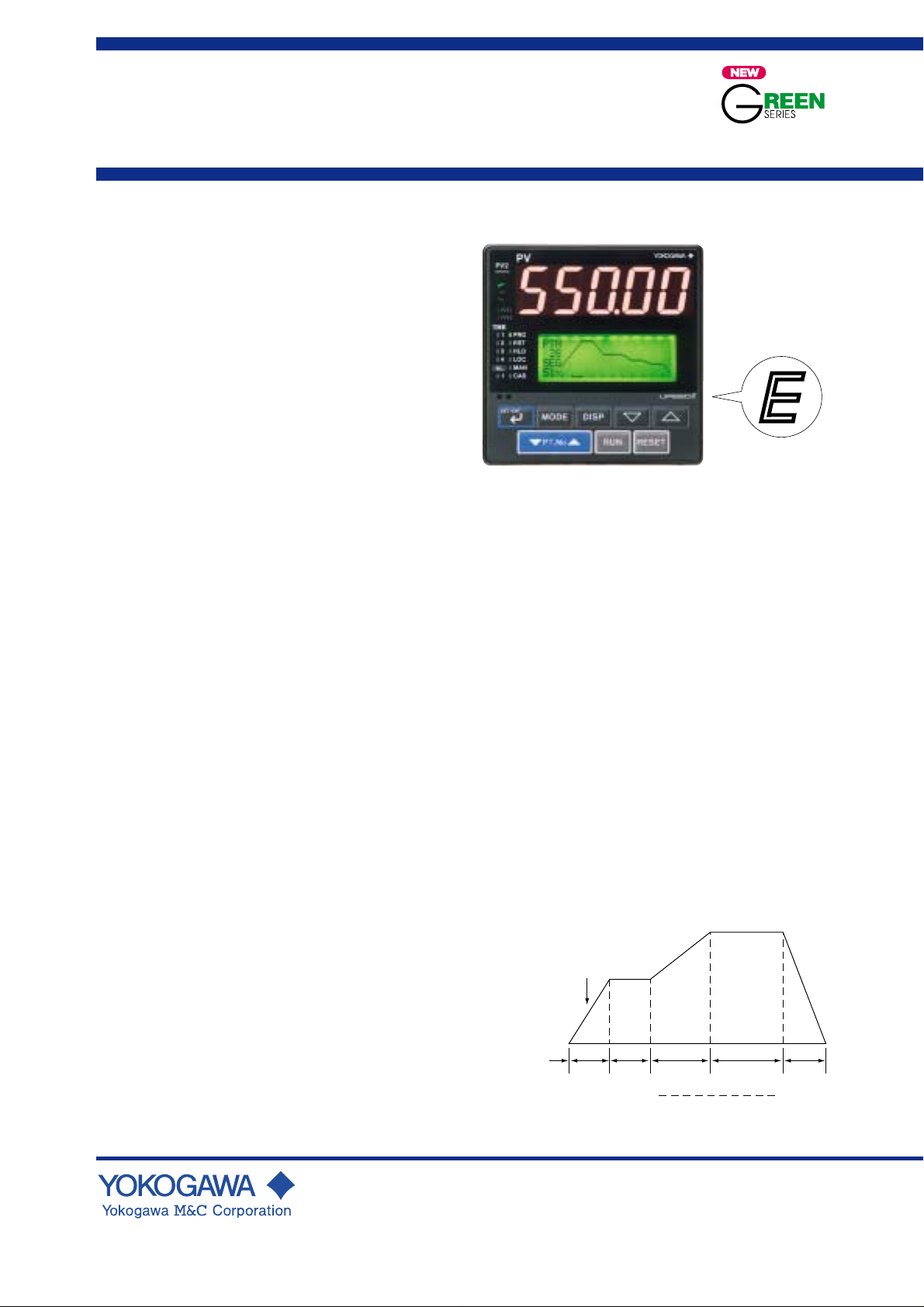
Model UP550 Program Controller can store up to 30
program patterns, and has a powerful control capability and
the user-friendly large numerical display. The UP550 features
as standard many functions which are necessary for various
control applications, and all of these functions such as
program setting function, control function, control computation function, signal computation function, etc. can be
configured by using the keys on the front panel. The
instrument has five types of control strategies, and also an
overshoot suppressing function "SUPER" and a heating
suppressing function "SUPER 2" built in as standard, as
well as an auto-tuning function.
■Main Features
• Extra-large digital display allows the indicated values to be
read even from a long distance. LEDs of 20 mm height are
used for the process variable display.
This is a five-digit display for heigher resolution.
• User-friendly, full-dot LCD display, capable of showing
not only control setpoints (SPs) and parameters but also
program patterns and deviation (DV) trend logs.
• Program setting function with storage capacity for up to 30
program patterns and 300 program segments, allowing the
controller to be used for a wide range of heat-treatment
applications.
• Five types of control function, including single-loop
control, cascade control, loop control with PV autoselector, enabling the operator to start control operation
immediately after simply entering the settings.
• The program pattern-2 retransmission function outputs a
program pattern by way of the retransmission output. This
function is used in combination with retransmission output
setup parameter RET 1 or RET 2, for which program
pattern-2 should selected, and is used for pattern
transmission to another instrument(available for UP made
1, 2, 6 or 7).
• Parameters and program patterns can be easily set using a
personal computer. ("Parameter setting tool (model
LL100)" sold separately is required.)
• Universal input and output enables users to set or change
freely the type of measured inputs, measurement input
range, type of control output, etc. from the front panel.
• Contact inputs (up to 7 points) and contact outputs (up to 7
points) can be employed and functions can be assigned to
each contact (the maximum number of points varies
depending on the specification code), with one additional
contact input available by specifying the appropriate suffix
code. (Contact outputs can be increased up to eight; see
"Number of Event/Alarm Outputs" on page 2 or "Contact
Outputs" on page 7.)
• Various communication function are provided. Communication is possible with personal computer, programable
logic controller, and other controllers.
UP550
UP550E
“E” indicates with the
model with expanded
functions.
■Functional Specifications
● Program Setting Function
The program setting function increases or decreases the value
of a target setpoint (SP) according to a given program pattern
that varies with time. The controller stores two or more
program patterns and the operator can switch between them
according to the operating status. Each program pattern
consists of multiple line segments (program segments). The
operator sets the time interval of each program segment using
the segment time or slope. The operator can also set such
instructions as the number of repeats, start/stop, and status
output (event output) for a given program pattern.
Number of program patterns: 30 maximum
Number of program segments per pattern: 99 maximum
Number of program segments: 300 maximum (sum of
Configurable number of events: 400 maximum (sum of
Number of program repeats:
Segment time: 0 minute 0 s to 59 minute 59 s, o r 0 h 0
Start/stop of program pattern:
Switching between program patterns:
Target setpoint (SP)
Segment time
segments for all program patterns)
events for all program patterns)
999 maximum, or unlimited repeats.
minute to 99 h 59 minute.
Program patterns can be started (RUN),
stopped (RESET), paused (hold) or advanced
by means of contact inputs or from instrument
operation.
Achieved by contact inputs or from instrument
operation.
1 t2 t3 t4 t5
t
Segment
No. 1
Example of Program Pattern
Segment
No. 2
Segment
No. 5
GS 05E01C02-01E
© Copyright Feb. 2000 (YK)
1st Edition Mar. 2000 (YG)
Page 2

<<Contents>> <<Index>>
2
Wait Function
The wait function delays the execution of a program pattern
when a process-variable (PV) input fails to keep track of
changes in the given target SP. The wait function has two
parameters: a wait zone and a wait time. The wait zone is a
margin of deviation that is used to judge how precisely the
PV input is tracking. The wait time is the time to wait for a
PV input to reach the wait zone. If a PV input reaches the
wait zone within the given wait time, the program advances
to the next segment. Even if the PV input fails to reach the
wait zone within the given wait time, the program also
advances to the next segment when the wait time elapses.
Wa it time: OFF, or 0 minute 1 s to 99 minute 59 s or
0 h 1 minute to 99 h 59 minute.
Wait zone: 0 to 10% of measured input range width.
UP Modes and Program Setting Function
The UP modes with a single program setting function are:
Single-loop control, cascade primary-loop
control, loop control with PV switching, loop
control with PV auto-selector, and cascade control.
Note that, in cascade control, the program
setting function acts on the primary-loop only.
Program Setting Function and PID Parameters
Switching
The controller can switch between PID parameter sets as a
program pattern progresses.
Segment PID selection:
PID-parameter numbers being used can be
selected on a segment basis.
Zone PID selection:
PID parameter sets are switched depending on
the value of the applied PV input. Either the
reference point method (reference point: a
setpoint for switching between PID parameter
sets) or the reference deviation method is used
for the switching.
Reference point method:
Divides the measuring input range into as
many as seven zones using a maximum of
six reference points, and switching between
PID parameter sets is done on a zone basis.
Reference deviation method:
Switches between PID parameter sets
depending on whether the control deviation
(DV) is within the given reference deviation
or exceeding the deviation. This method has
priority over the reference point method
during operation.
Time Events
The time event function notifies the progress of a program
pattern, such as the time when the program moves from one
segment to another, by means of an indicator lamp or contact
output.
Configurable number of time events: Max.8 points
Time event setpoint:
Allows the controller to output a time event
ON or OFF after the lapse of a specific time
from when the program switches from one
segment to another. The lapse of time is
configurable between 0 minute 0 s and 99 h 59
minute.
Number of time event indicator lamps: 4 points (TME 1, 2,
3, 4)
PV Events
The PV event is a PV/DV alarm function defined within a
given program pattern.
Configurable number of PV events: 8 points maximum
PV event indicator lamps: 2 points (PVE1 and PVE2)
Event types: PV high limit, PV low limit, Deviation high
limit, Deviation low limit, Deenergized on
deviation high limit, Deenergized on deviation
low limit, Deviation high and low limits, High
and low limits within deviation, Deenergized
on PV high limit, Deenergized on PV low
limit, SP high limit, SP low limit, Output high
limit, Output low limit.
Configurable ranges of PV events:
PV alarm: -100 to 100% of measured input
range
DV alarm: -100 to 100% of measured input
range width
Alarm hysteresis: 0.0 to 100.0% of measured
input range width
Instrument Alarm Functions
The instrument alarm function outputs PV, deviation, SP,
and other alarm without regards to the program pattern.
Controller has four instrument alarm outputs.
Alam types: PV high limit, PV low limit, Deviation high
limit, Deviation low limit, Deenergized on
deviation high limit, Deenergized on deviation
low limit, Deviation high and low limits, High
and low limits within deviation, Deenergized
on PV high limit, Deenergized on PV low
limit, SP high limit, SP low limit, Output high
limit, Output low limit.
Alarm setting range:
PV/SP alarm: -100 to 100 % of measured
input range.
Deviation alarm: -100 to 100 % of measured
input range width.
Output alarm: -5.0 to 105.0 % of output value.
Alarm hysteresis: 0.0 to 100.0 % of measured
input range width.
Stand-by action:
Stand-by action can be set to make PV/
deviation alarm OFF during start-up or after
SP change until SP reaches the normal region.
Other alarm actions:
Sensor grounding alarm: Detects sensor
deterioration and outputs an alarm.
Fault diagnostic alarm:
Input burnout, A/D conversion error, RJC error
FAIL output:
Abnormality in Software, Abnormality in
Hardware
Number of Instrument Alarm Settings: 4 points
Number of Instrument Alarm Outputs: Max. 4 points
One of PV alarm/Deviation alarm, Fault
diagnostic alarm, Sensor grounding alarm and
Fail output can be output with contact output.
(Note): Refer to the later "Contact Outputs" in
Hardware Specifications.
All Rights Reserved. Copyright © 2000, Y okogawa M&C Corporation
GS 05E01C02-01E 1st Edition Mar. 31, 2000-00
Page 3

<<Contents>> <<Index>>
3
Number of Event/Alarm Output
(See "Contact Output," later in this brochure.)
• As many as seven event and instrument alarms in
combination can be output using contact outputs (standard
feature). (Note that a control output relay can be used as
the output device of time event number 5. This increases
the number of contact outputs to eight.)
• Number of contact (relay) outputs:
3 (standard), or 4 (if a control output relay is
used as the output device of time event
number 5)
• Number of contact (open-collector transistor) outputs:
4 (standard)
From the above, up to 8 point outputs can be obtained.
• Any of Time Events, PV Events and Instrument Alarm
function can be assigned to contacts for the above number
of outputs. However, the timer delay alarm can be
assigned to the first alarm output only. Also, the fifth time
event is assignable only to the control output relay. Events
and the alarm status can be read via communication in
addition to output as the above alarm output.
• The controller is shipped from the factory with the
following settings:
Number of time events: 4
Number of PV events: 2
Number of instrument alarms: 1
● Control Functions
UP Mode
The following types of basic control can be set as the UP
mode by the user.
Single-loop control (UP mode 1):
The most simple and basic control function.
Cascade primary-loop control (UP mode 2):
Output tracking function and cascade control
logic are provided. Suitable for primary-loop
cascade control.
Cascade control (UP mode 4):
Dual control function for cascade control in a
single instrument.
Loop control with PV switching (UP mode 6):
Two measured inputs are switched for control
depending on the value of contact input or
measured input.
Loop control with PV auto-selector (UP mode 7):
Two measured inputs are automatically
selected for control with a high, low, average
or temperature-difference selector.
● Control Computation Functions
In each UP mode, the following types of control computation can be selected:
Continuous PID control, Time proportional
PID control, Position proportional PID control
(for UP550-1■), Relay ON/OFF control, and
Heating/Cooling control (for UP550-2■).
Number of PID parameter sets:
Up to eight sets can be set; eight sets each for
the main loop and slave loop in the case of
cascade control.
Auto-tuning: Available as standard. Possible to activate
auto-tuning for both main and slave loops for
cascade control.
"SUPER" function:
Overshoots generated by abrupt changes in the
target setpoint or by disturbances can be
suppressed.
"SUPER 2" function:
This function stabilizes the state of control
that is unstable due to hunting, etc. without
requiring any change in PID constants, when
the load and/or gain varies greatly, or when
there is a difference between the characteristics of temperature zones.
Preset output function:
When the instrument is in Stop mode,
measured input is burnt-out, or an abnormality
is found in an input circuit, a preset setpoint is
output as a control output.
Control cycle time
Each cycle time can be selected under the
following conditions:
100 ms: Available when UP mode is not cascade
control (UP mode 4).
200 ms: Available when UP mode is cascade control
(UP mode 4).
(Set value when shipped from the factory: 200 ms)
Operation Mode Switching
(Note: Communication enables all the following
mode switching to be executed.)
AUTO/MANUAL switching:
Bumpless switching between automatic
operation mode and manual control mode is
available by using instrument operation or
contact input. The contact input has priority
over instrument operation or switching by
communication.
RUN (PRG)/STOP (RESET) switching:
Bumpless switching from Run to Stop mode is
available by using the front key or contact
input. The contact input has priority over the
front key or switching by communication.
Control computation is valid in Run mode but
not in Stop mode. The preset value is output
as a control output. Other functions operate
normally.
CASCADE/Local SP switching:
Switching between the cascade, automatic and
manual operating modes is available by using
instrument operation or contact input when in
Cascade control. The contact input has
priority over instrument operation or switching by communication.
Control Parameters Setting Range
Proportional band: 0.1 to 999.9%
0.0 to 999.9% (for heating/cooling PID
control), 0.0% available for ON/OFF control.
Integral time: 1 to 6,000 s, or OFF (for Manual reset)
Derivative time: 1 to 6,000 s, or OFF
ON/OFF control hysteresis: 0.0 to 100.0% of measured
input range width
Preset output value: -5.0 to 105.0% (0 mA or less cannot
be output)
Output limiter:
Setting range: -5.0 to 105.0% for both high
and low limits
However, "low limit setpoint < high limit
setpoint" must be satisfied.
In case of heating/cooling PID control, upper
limiter for heating and upper limiter for
cooling.
All Rights Reserved. Copyright © 2000, Y okogawa M&C Corporation GS 05E01C02-01E 1st Edition Mar. 31, 2000-00
Page 4
<<Contents>> <<Index>>
4
Shutdown function:
When manual control is carried out with 4 to
20 mA output, control output can be output
down to about 0 mA (shutdown is specified
for -5.0% or less).
Rate-of-change limiter for output: OFF or 0.1 to 100.0%/s
Deadband for heating/cooling control: -100.0 to 50.0% for
output value
Deadband for position-proportional control: 1.0 to 10.0%
for output
● Configuration of Input/Output Signal
Measured Input Computations
Input processing, Square root extraction (voltage input only,
Input low cut 0.0 to 5.0%), Ten-segment linearizer function,
Segment bios, Bias addition (-100.0 to 100.0%), and First
order lag filter (off, time constant 1 to 120 s)
Auxiliary Input Computations
Input processing, Square root extraction (Input low cut 0.0 to
5.0%), Bias addition (-100.0 to 100.0%), Ratio multiplication
(0.001 to 9.999), First order lag filter (OFF, time constant 1
to 120 s)
● Display and Operation Functions
PV Display
The controller display either PV1 or PV2 (only during
cascade control), when switched, on the 5-digit display.
The number of display digits is 4 or 5. For thermocouple or
RTD, data below the decimal point can be set not to display.
The display range is -19999 to 30000 and the display span is
30000 or less. [550.00 appearing in the product photograph
on page 1 cannot actually be displayed.]
LCD Display
Some data are displayed on LCD display unit. Each screen is
called “display”.
Five types of display are provided; Operating display,
Operating parameter setting display, Program parameters
setting display, Setup parameter setting display and SELECT
display.
Operating display:
Necessary data for operation is displayed
according to UP mode.
Such items as Pragram pattern, Setpoint,
Control Ouput, control output bar, deviation
trend is displayed. Time base of deviation
trend is 120 s to 20 h.
Operating parameters setting display:
The Operating paramters, which are mainly
changed during operation, such as PID
constant, are displayed.
Program Parameters Setting display:
Setting of Program pattern, stand-by action,
parameters of Repeat action are displayed.
Setup Parameters Setting display:
The Setup parameters to configure functions
of the instrument before starting operation are
displayed. The explanation of each parameters
is provided.
UT mode is set in this display.
SELECT display:
Up to five displays which are frequently
accessed can be selected from Operating
parameter setting display and Setup parameters setting display.
Status Lamps
Event indicator lamps:
Seven lamps, TME1, TME2, TME3, TME4,
PVE1, PVE2, and AL1
Operation mode indicator lamps:
PRG (program operation), RST (operation at a
stop), HLD (operation hold), LOC (local
setting), MAN (manual operation), CAS
(cascade operation), and PV2 (process
variable 2)
Operation Keys
▲, ▼keys: Increase or decrease setpoints and other
parameters displayed on the LCD display.
DISP key: Switches from one data value to another on
the LCD display.
SET/ENT key: Used for setting or changing set data,
switching the LCD displayed contents, and
switching operation modes except for A/M.
MODE key:Switches between the operating modes.
䉮PT. No 䉭 key:
Selects the pattern number.
RUN key: Initiates the program operation.
RESET key: Stop and reset the program operation.
Security Function
Key-lock from parameter setting and,
operation can be inhibited by a password.
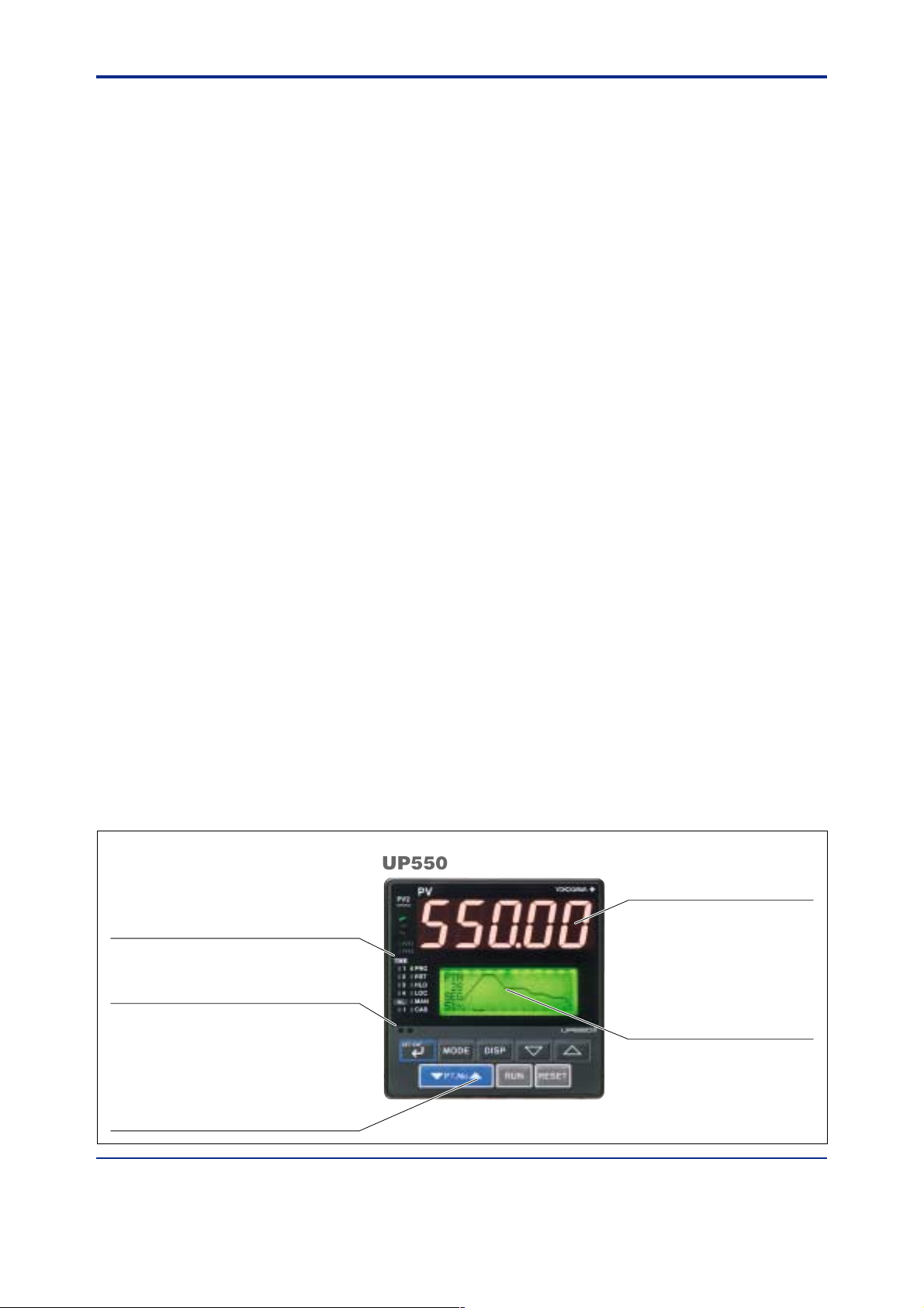
Status lamps
Indicates PV2 reading (PV2), time events (TIME1
to TIME4), PV events (PVE1 and PVE2),
instrument alarm (AL1), program operation (PRG),
stop of program operation (RST), operation hold
(HLD), local operation (LOC), manual operation
(MAN), and cascade operation (CAS).
Communication port for light loader
Parameters and programs are set via
communication from a personal computer.
Operation keys
Increase/decrease the setpoint values (▲, ▼),
switch between displays (DISP), switch between
operation modes (MODE), select between
parameters/set values (SET/ENT), switch between
program patterns (䉭PT. No䉮 ), start program
operation (RUN), and stop program operation
(RESET).
All Rights Reserved. Copyright © 2000, Y okogawa M&C Corporation
Measured value (PV) display unit
Displays PV and error codes when
errors are detected.
LCD display unit
Displays the setpoint value (SP),
program pattern, output value, bar
graph (of deviations), deviation,
deviation trend, valve opening, and
the setting item and setting value of
a parameter, etc.
GS 05E01C02-01E
1st Edition Mar. 31, 2000-00
Page 5
<<Contents>> <<Index>>
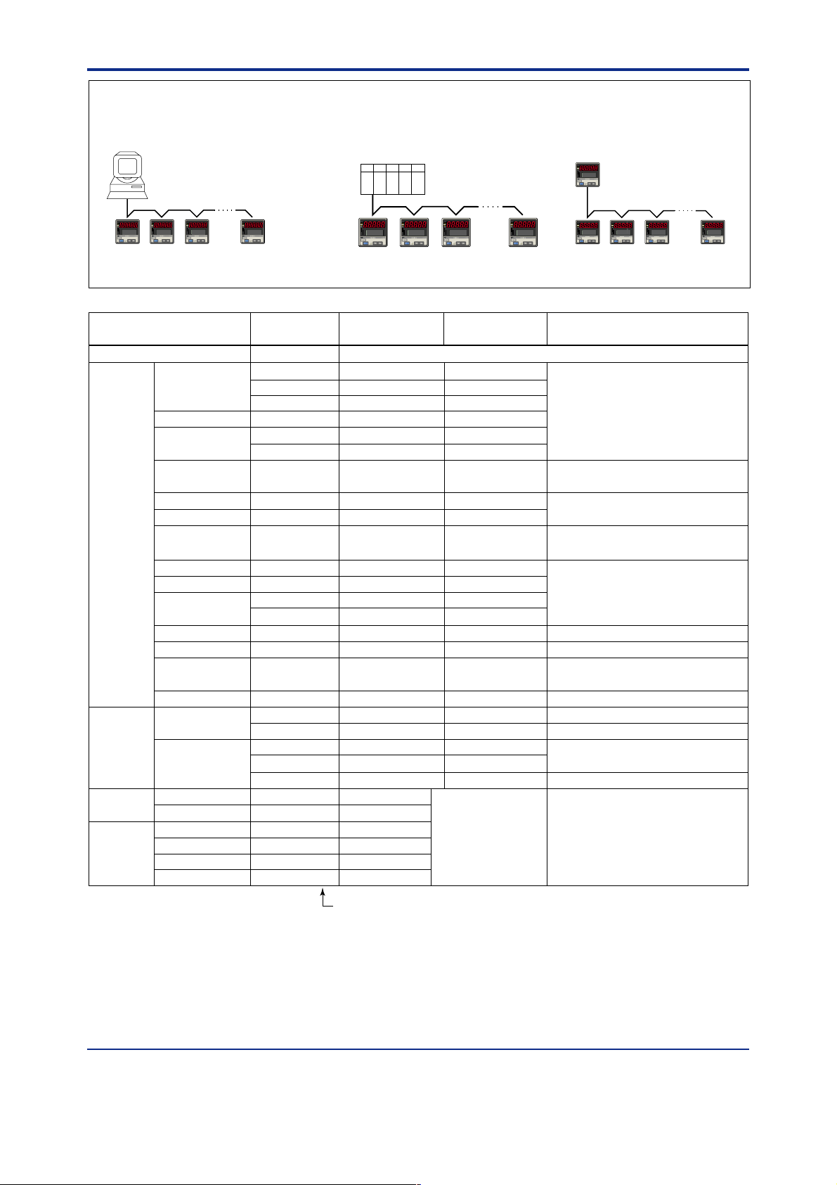
Examples of Communication System Configuration Diagram
(1) Personal computer link communication/
MODBUS communication
Personal computer
PV
PV
PV2
PV2
AL
AL
1
1
2
2
REM
REM
3
3
MAN1
MAN1
4
4
MAN2
MAN2
STP
STP
CAS
CAS
A/M
A/M
DISP
DISP
SET/ENT
SET/ENT
UP550
program controller
PV
PV2
AL
1
2
REM
3
MAN1
4
MAN2
STP
CAS
A/M
DISP
SET/ENT
PV
PV2
AL
1
2
REM
3
MAN1
4
MAN2
STP
CAS
A/M
DISP
SET/ENT
(2) Ladder communication (3) Coordinated operation
MELSEC-A
Programmable
controller
PV
PV2
AL
1
1
2
3
REM
4
MAN1
MAN2
STP
CAS
A/M
UP550
program controller
PV
PV2
AL
1
2
3
REM
4
MAN1
MAN2
STP
CAS
A/M
DISP
SET/ENT
DISP
SET/ENT
5
UP550 (or UP750) program controller
PV
PV2
AL
1
2
REM
3
MAN1
4
MAN2
STP
CAS
A/M
DISP
SET/ENT
PV
PV2
AL
1
2
3
REM
4
MAN1
MAN2
STP
CAS
A/M
DISP
SET/ENT
PV
PV2
AL
1
2
3
REM
4
MAN1
MAN2
STP
CAS
A/M
DISP
SET/ENT
PV
PV
PV2
AL
1
2
REM
3
MAN1
4
MAN2
STP
CAS
A/M
DISP
SET/ENT
PV
PV2
PV2
AL
AL
1
1
2
2
3
REM
REM
3
4
MAN1
MAN1
4
MAN2
MAN2
STP
STP
CAS
CAS
A/M
A/M
DISP
DISP
SET/ENT
SET/ENT
PV
PV2
AL
1
2
3
REM
4
MAN1
MAN2
STP
CAS
A/M
DISP
SET/ENT
UT750, UT550, UT520, UT350 or
UT320 digital indicating controller
Input type
Input range
code
Unspecified (When shipped from the factory)
Thermocouple
K
typeK1 (1)
typeK2 (2)
typeK3 (3)
J
T
typeJ (4)
typeT1 (5)
typeT2 (6)
B
S
R
N
E
L (DIN)
U (DIN)
typeB (7)
typeS (8)
typeR (9)
typeN (10)
typeE (11)
typeL (12)
typeU1 (13)
typeU2 (14)
typeW (15)
plati2 (16)
PR2040 (17)
W97Re3 (18)
JPt1 (30)
RTD
W
Platinel 2
PR20-40
W97Re3-W75Re25
JPt100
JPt2 (31)
Pt100
Pt1 (35)
Pt2 (36)
Pt3 (37)
Standard
signal
DC voltage
0.4 to 2V
1 to 5V
0 to 2V
0 to 10V
-10 to 20mV
0 to100mV
0.4 to 2V (40)
1 to 5V (41)
0 to 2V (50)
0 to 10V (51)
mV1 (55)
mV2 (56)
OFF
Instrument
range (°C)
Instrument
range (°F)
Instrument accuracy
*1
Set the data item PV input type “IN 1” to the OFF option to leave the PV input type undefined.
-270.0 to 1370.0°C
-270.0 to 1000.0°C
-200.0 to 500.0°C
-200.0 to 1200.0°C
-270.0 to 400.0°C
0.0 to 400.0°C
0.0 to 1800.0°C
0.0 to 1700.0°C
0.0 to 1700.0°C
-200.0 to 1300.0°C
-270.0 to 1000.0°C
-200.0 to 900.0°C
-200.0 to 400.0°C
0.0 to 400.0°C
0.0 to 2300.0°C
0.0 to 1390.0°C
0.0 to 1900.0°C
0.0 to 2000.0°C
-200.0 to 500.0°C
-150.00 to 150.00°C
-200.0 to 850.0°C
-200.0 to 500.0°C
-150.00 to 150.00°C
0.400 to 2.000 V
1.000 to 5.000 V
0.000 to 2.000 V
0.00 to 10.00 V
-450.0 to 2500.0°F
-450.0 to 2300.0°F
-200.0 to 1000.0°F
-300.0 to 2300.0°F
-450.0 to 750.0°F
-200.0 to 750.0°F
32 to 3300°F
32 to 3100°F
32 to 3100°F
-300.0 to 2400.0°F
-450.0 to 1800.0°F
-300.0 to 1600.0°F
-300.0 to 750.0°F
-200.0 to 1000.0°F
32 to 4200°F
32.0 to 2500.0°F
32 to 3400°F
32 to 3600°F
-300.0 to 1000.0°F
-200.0 to 300.0°F
-300.0 to 1560.0°F
-300.0 to 1000.0°F
-200.0 to 300.0°F
Display range
-19999 to 30000
Display span 30000 or
less (Decimal point
position changeable)
±0.1% ±1 digit of instrument range at 0°C or more
±0.2% ±1 digit of instrument range at less than 0°C
• However, ±2% ±1 digit of instrument range for type K
at temperatures less than -200°C.
However, ±1% ± 1 digit of instrument range for type T
•
at temperatures less than -200°C.
±0.15% ±1 digit of instrument range at 400°C or more
±5% ±1 digit of instrument range at less than 400°C
±0.15% ± 1 digit of instrument range
±0.1% ± 1 digit of instrument range
±0.25% ±1 digit of instrument range for
temperature at less than 0°C
±0.1% ±1 digit of instrument range at 0°C or more
±0.2% ±1 digit of instrument range at less than 0°C
• However, ±1.5% ±1 digit of instrument range for
type E at temperature less than -200°C.
±0.2% ±1 digit of instrument range
±0.1% ± 1 digit of instrument range
±0.5% ±1 digit of instrument range at 800°C or more
Accuracy not guaranteed for temperature less than
800°C
±0.2% ± 1 digit of instrument range
±0.1% ± 1 digit of instrument range (Note1) (Note2)
±0.2% ± 1 digit of instrument range (Note1)
±0.1% ± 1 digit of instrument range (Note1) (Note2)
±0.2% ± 1 digit of instrument range (Note1)
±0.1% ± 1 digit of instrument range
-10.00 to 20.00 mV
0.0 to 100.0 mV
Numbers in ( ) are the measurement input range codes that
apply when the communication function is used.
*1: Performance in the standard operating conditions (at 23± 2°C, 55± 10% RH, and 50/60 Hz power frequency)
Note 1:The accuracy is ±0.3°C of instrument range ±1 digit for a temperature range from 0 to 100°C
Note 2:The accuracy is ±0.5°C of instrument range ±1 digit for a temperature range from –100 to 200°C.
All Rights Reserved. Copyright © 2000, Y okogawa M&C Corporation GS 05E01C02-01E
1st Edition Mar. 31, 2000-00
Page 6

<<Contents>> <<Index>>
6
● Communications Function
(For UP550-■1 only)
This controller has 4 types of communication protocol with
one communication interface. Communication is possible
with personal computer, programmable logic controller, and
other controllers.
Communication Protocol
Computer link communication:
Communication protocol with a personal
computer.
Ladder communication:
Communication protocol with the ladder
program on some programmable logic
controllers.
MODBUS communication:
Communication protocol with a personal
computer or PLC.
Coordinated operation:
Protocol used to communicate with more than
one UT750, UT550, UT520, UT350 or UT320
controller. The UP550 always serves as the
master station.
RS-485 Communication Interface
The RS-485 communication interface (conforms to EIA RS-
485) can be used for computer link or ladder communication,
or for coordinated operation.
Maximum number of connectable UP550's:
31 (total including other UT, UP, or UM
models)
Maximum communication distance: 1200 m
Communication method:
Two-wire half-duplex or four-wire half-
duplex, start-stop synchronization, and non-
procedural
Communication rate: 600, 1200, 2400, 4800, or 9600 bps
■Hardware Specifications
● Input/Output Signal Specifications
Measured Input Signal
Number of input points: 1 point
Input type, measurement range, and measurment accuracy:
The type of input and measurement range can
be specified using the input range code shown
in the table on page. 5.
Sampling period: 100, 200, or 500 ms (selectable)
Burnout detection: Activated for thermocouple (TC) input,
RTD input, or standard signal of 0.4 to 2 V
DC or 1 to 5 V DC.
Possible to specify a travel of upscale,
downscale, or off.
For standard signal input, set to burn out at
Approx. 0.1V.
Input bias current: 0.05 µA (for TC or RTD b-terminal)
Specified current(RTD): about 0.13 mA
Input resistance: 1 MΩ or more for TC or mV input
About 1 MΩ for DC voltage input
Allowable signal source resistance:
250Ω or less for TC or mV input Signal
source registance effect 0.1 µV/Ω or less
2 kΩ or less for DC voltage input
Allowable signal source resistance effect:
0.01%/100 Ω or less
Allowable leadwire resistance (for RTD input):
Maximum 150 Ω/one wire (Lead resistances
of three wires must be equal.)
However, it must be 10 Ω/one wire for the
range of -150.0 to 150.0˚C.
Effect of wiring resistance: ±0.1˚C/10 Ω
Allowable input voltage:
±10 V DC for TC/mV/RTD input
±20 V DC for DC voltage input
Noise rejection ratio:
Normal mode 40 dB (50/60 Hz) or more
Common mode 120 dB (50/60 Hz) or more
Reference junction compensation error:
±1.0˚C (15 to 35°C), ±1.5˚C (0 to 15°C and
35 to 50°C)
Applicable standards: JIS, IEC, and DIN (ITS-90) for TC
and RTD
Auxiliary Analog Input
(For UP550-■1 only)
Functions: PV input to secondary-loop of cascade
control, etc.
Input type: Settable within the range of voltage input 0 to
2 V DC, 0 to 10 V DC, 0.4 to 2.0 V DC or 1
to 5 V DC.
Number of inputs: 1 point
Sampling period: 100, 200 or 500 ms
auxiliary analog input period is linked with
PV sampling period.
Input resistance: Approx. 1 MΩ
Input accuracy: ±0.3% ±1 digit of F.S. for 0 to 2 V DC
input
±0.2% ±1 digit of F.S. for 0 to 10 V DC input
±0.375%±1 digit of F.S. for 0.4 to 2.0 V DC
input.
±0.3%±1 digit of F.S. for 1 to 5 V DC input.
Performance in the standard operating
conditions (at 23± 2°C, 55± 10% RH, and 50/
60 Hz power frequency)
Feedback Resistance Input
(For UP550-1■ only)
Effective for position proportional PID control only
Slidewire resistance:
Total resistance 100 Ω to 2.5 kΩ (with
detection of slidewire breakage)
Measuring resolution ±0.1% of total
resistance
Retransmission Output
Any of the measured value, target setpoint or control output
is output. This output can be used for the 15 V DC loop
power supply sensor.
Number of output points: 1 or 2 (depend on selection of
control output)
Retransmission output 2 is available only
when “relay” is selected as the control
function.
Output signal: 4 to 20 mA DC, 0 to 20 mA DC, 20 to 4
mA DC or 20 to 0 mA DC (0 mA or less
cannot be output)
Load resistance: 600 Ω or less
Output accuracy: ±0.1% of span (±5% for 1 mA or less)
Performance in the standard operating
conditions (at 23± 2°C, 55± 10% RH, and 50/
60 Hz power frequency)
When using for 15 V DC loop power supply:
All Rights Reserved. Copyright © 2000, Y okogawa M&C Corporation
GS 05E01C02-01E
1st Edition Mar. 31, 2000-00
Page 7

<<Contents>> <<Index>>
7
Supply voltage 14.5 to 18.0 V DC, maximum supply
current about 21 mA (with the protection
circuit at field short-circuit)
■
15 V DC Power Supply Wiring to Two-wire Sensor
External
resistor
(Note)
Two-wire transmitter
4-20mADC
Note: Connecting a 100 Ω resistor to the terminals is optional.
Model: X010-100-2 (resistor with M3.5 crimp-on terminal lugs)
12
100Ω
13
14
15
PV input
0.4 to 2.0 V DC signal
Loop power
supply
14.5 to
18.0 V DC
Control Outputs
Select 1 point (UP550-0■) or 2 points (UP550-2■) from the
following output types depending on the model code. Relay
contact output for position-proportional PID control (UP5501■).
Current output
Number of output points: 1 or 2 (for heating/cooling
type) (switchable to voltage pulse output)
Output signal: 4 to 20 mA DC, 0 to 20 mA DC, 20 to 4
mA DC or 20 to 0 mA DC
Load resistance: 600 Ω or less
Output accuracy: ±0.1% of span (±5% for 1 mA or less)
Performance in the standard operating
conditions (at 23± 2°C, 55± 10% RH, and
50/60 Hz power frequency)
Voltage pulse output
Number of output points: 1 or 2 (for heating/cooling
type) (switchable to current output)
Output signal: On voltage 12 V DC or more (load
resistance 600 Ω or more)
Off voltage 0.1 V DC or less
Resolution: 10 ms or 0.1% of output value, whichever is
greater
Relay contact output
Number of output points: 1 or 2 (for heating/cooling
type)
Output signal: At three terminals of NC, NO and
Common
Contact rating: 250 V AC, 3 A or 30 V DC, 3 A
(resistive load)
Resolution: 10 ms or 0.1% of output value, whichever is
greater
Contact Inputs
Application: Program pattern switching, Local/Remote
switching, PRG/RESET switching, Pause of
operation, Advance of program, Measured
input switching, and display of messages.
Number of input points:
7 (UP550-■0)
8 (UP550-■1)
Input type: Non-voltage contact input or transistor open
collector input
Input contact rating: 12 V DC, 10 mA or more
On/off detection:
For non-voltage contact input,
On contact resistance 1 kΩ or less;
Off contact resistance 20 kΩ or more
For open-collector transistor input,
On 2 V or less;
Off leak current 100 µA or less
Minimum retention time for status detection: PV input
sampling period ×3
Contact Outputs
Application: Time event outputs, PV event outputs, and
instrument alarm outputs
Number of outputs: 7 points (3 relay-contact outputs and 4
transistor outputs), where a control output
relay can be used as a contact-output relay for
time event No. 5 if no relays are in use for
control output. This enables the number of
outputs (seven) to be increased to eight by
adding one more relay output.
Relay contact rating: 240 V AC, 1 A or 30 V DC, 1 A
(Common to COM terminal)
Transistor contact rating: 24 V DC, 50 mA (Common to
COM terminal)
● Display Specifications
Measured value (PV) display:
Data display: 32 × 128 dot-matrix LCD display with back-
Status indicator lamps: LEDs
5 digit seven-segment red color LED display;
height of letters 20 mm
light
● Conformance to Safety and EMC Standards
Safety standard:
EMC Standard:
Conforms to IEC1010-1: 1990 and EN610101: 1992
Certified for CSA1010
The overvoltage category of each input is
CAT II (IEC1010-1)
Certified for UL508 application
To the following EMC standards. During test,
the controller continues to operate with the
measurement accuracy within ±20% of the
range:
EMI (emission), EN55011, Class A Group 1
EMS (immunity), EN50082-2: 1995
● Construction, Installation, and Wiring
Construction: Dust-proof and Drip-proof front panel
Material of the body: ABS resin and polycarbonate
Case color: Black
Weight: Approx. 1 kg or less
External dimensions: 96W × 96H × 100D (from the panel
Mounting: Direct panel mounting; mounting bracket, one
Panel cutout dimensions:
Tilting: Up to 30 degrees from horizontal; Must not
Wiring connection: With M3.5 screw terminals (for signal,
conforming to IP55.
For side-by-side close installation, controller
loses its dust-proof and drip-proof protection.
face) (mm)
each for upper and lower mounting
92
+0.8
0
W ×
92
+0.8
H (mm)
0
face downward.
power and grounding wiring)
All Rights Reserved. Copyright © 2000, Y okogawa M&C Corporation GS 05E01C02-01E
1st Edition Mar. 31, 2000-00
Page 8

<<Contents>> <<Index>>
8
● Power Supply and Isolation
Power supply: Rated voltage 100 to 240 V AC (±10%),
Power consumption: MAX. 20 VA or less (MAX. 8.0 W)
Lithium battery: For memory backup. Service life approx.
Withstanding voltage:
1500 V AC for 1 min.
1500 V AC for 1 min.
1500 V AC for 1 min.
500 V AC for 1 min.
Isolation resistance:
Grounding: Class 3 grounding (grounding registance of
Isolation Specifications
Measured input terminal:
Auxiliary analog input terminal:
Control output (current output or voltage pulse output) and
Relay contact control output terminals:
Contact input terminals:
Relay contact output terminals:
Transistor contact output terminals:
RS-485 communication terminals:
50/60 Hz
10 years
(Note)
between primary terminals and secondary
terminals
(Note)
between primary terminals and ground
terminal
between ground terminal andsecondary
terminals
between secondary terminals
where primary terminals stand for power
and relay output terminals and secondary
terminals stand for analog input or output
signal terminals, voltage pulse output
terminals, and contact input terminals.
Note: The withstanding voltage is specified as
2300 V AC per minute to provide a margin
of safety.
20 MΩ or more for 500 V DC applied
between power terminals and ground terminal
100Ω or less).
Isolated from other input/output terminals, but
not isolated from internal circuits.
Isolated from other input/output terminals and
internal circuits.
retransmission output: Not isolated between
controll output and retransmission output, but
isolated from other input/output terminals and
internal circuits.
Isolated from other input/output terminals and
internal circuits.
Not isolated from other contact input
terminals and communication terminals, but
isolated from other input/output terminals and
internal circuits.
Isolated from other input/output terminals and
internal circuits.
Not isolated from other contact outputs, but
isolated from other input/output terminals and
internal circuits.
Not isolated from contact input terminals, but
isolated from other input/output terminals and
internal circuits.
Feedback slide wire resistance input terminals:
Not isolated from control output (current or
voltage pulse control output) and retransmission output terminals.
Isolted from other input/output terminals and
internal circut.
Power terminals:
Isolated from other input/output terminals and
internal circuits.
Ground terminal:
Isolated from other input/output terminals and
internal circuits.
● Environmental Conditions
Normal operating conditions:
Ambient temperature: 0 to 50°C (40°C or less in close
Temperature change rate: 10°C/h or less
Ambient humidity: 20 to 90% RH (no condensation)
Magnetic field: 400 A/m or less
Continuous vibration (5 to 14 Hz): Peak-to-peak
Continuous vibration (14 to 150 Hz): 4.9 mm/s
Short period vibration: 14.7 µ/s
Shock: 147 m/s
Installation altitude: 2000 m or less above sea level
Warm-up time: 30 minutes or more
Transportation and storage conditions:
Temperature: -25 to 70°C
Temperature change rate: 20°C/h or less
Humidity: 5 to 95% RH (no condensation)
Effect of operating conditions
Effect of ambient temperature:
Effect of voltage fluctuation
(within rated voltage range):
mounting side-by-side)
amplitude 1.2 mm or less
2
2
or less, 11 ms
, 15 s or less
Whichever is greater, ±1 µV/°C or ±0.01%
of F.S./°C for voltage or thermocouple
inputs.
±0.02% of F.S./°C for Auxiliary input
±0.05°C/°C (ambient temperature) or less
for RTD inputs.
±0.05% of F.S./°C or less for analog
outputs.
Whichever is greater, ±1 mV/10 V or
±0.01% of F.S./10 V for analog inputs.
±0.05% of F.S./10 V or less for analog
outputs.
2
or less
All Rights Reserved. Copyright © 2000, Y okogawa M&C Corporation
GS 05E01C02-01E 1st Edition Mar. 31, 2000-00
Page 9

<<Contents>> <<Index>>
■Fuction Block Diagram for Single-loop Control
PV input
terminals , and
12 1311
Contact input
9
INPUT1
Input selection
Unit selection
Analog input range conversion
Analog input bias
Square root extraction
Analog input filter
10-seg. linearizer approx./bias
PV input bias
PV input filter
Manual operation
A/M
Preset output
RUNSTOP
OT1
DI1 DI2 DI3 DI4 DI8 DI7
Start of program operation
when DI changes from OFF to ON
DI6DI5
Stop of program operation
when DI changes from OFF to ON
Program
pattern selection
Program operation
Local
setpoint 1
Program
operation
Local
operation
Control computation
AUTOMAN
Output limiter
STOP/RUN switching
15 V loop
power supply
Retransmission
output
Start of local-mode operation
when DI changes from OFF to ON
Control
output
OUTPUT1 OUTPUT3
Current or pulse
terminals
and
OUTPUT1
Relay
terminals
2 31
, and
*1: Unavailable when control
output is current or pulse.
*2: Unavailable when control
output is relay.
*3: Only available for UP550-2䊐
Legend
RET2 RET1
OUTPUT1
Current*1
terminals
and
Current
terminals
and
1514
17161716
PV event output
Time event output
Instrument alarm output
OUTPUT1
Relay*2
terminals
2 31
, and
Time
event 5
OUTPUT2
Relay*3
terminals
49 5048
, and
Time
event 6
PV
event 1
PV
event 2
Instrument
alarm 1
Time
event 1
Terminal Parameter Function
Analog signal Contact signal
Time
event 2
Time
event 3
DO7DO6DO5DO4DO3DO2DO1
Time
event 4
All Rights Reserved. Copyright © 2000, Y okogawa M&C Corporation GS 05E01C02-01E
1st Edition Mar. 31, 2000-00
Page 10

<<Contents>> <<Index>>
■Fuction Block Diagram for Cascade Control
10
Cascade primary PV
input terminals
12 1311
, and
INPUT1
Input selection
Unit selection
Analog input range conversion
Analog input bias
Square root extraction
Analog input filter
10-seg. linearizer approx./bias
PV input bias
PV input filter
Local setpoint 2
Tracking signal
LSP/CAS
Contact input
DI1 DI2 DI3 DI4 DI5DI8 DI6 DI7
Start of program operation
Program
when DI changes from OFF to ON
pattern selection
Program operation
Local
setpoint 1
Program
operation
Local
operation
Control computation 1
Output limiter
LOCAL
CASCADE
LOCAL (OFF)/CASCADE (ON) switching
Secondary PV
input terminals
2221
and
INPUT3
Stop of program operation
when DI changes from OFF to ON
Input selection
Unit selection
Analog input range conversion
Analog input bias
Square root extraction
Analog input filter
10-seg. linearizer approx./bias
PV input bias
PV input filter
Manual operation
Preset output
RUNSTOP
OT2
Control output
OUTPUT1 OUTPUT1
Current or
pulse terminals
and
Legend
Relay
terminals
1716
2 31
, and
Terminal Parameter Function
Analog signal Contact signal
Control computation 2
MAN
Output limiter
15 V loop
power supply
RET2 RET1
OUTPUT1 OUTPUT3
Current*1
terminals
1716
and
LOCAL ,
CASCADE
Retransmission
output
Current
terminals
and
OUTPUT1 OUTPUT2
1514
Relay*2
Relay*2
terminals
terminals
, and
, and
Time
Time
event 5
event 5
STOP/RUN switching
DO1
PV
event 1
Relay*3
Relay*3
terminals
terminals
49 50482 31
49 50482 31
, and
, and
Time
Time
event 6
event 6
PV event output
Time event output
Instrument alarm output
PV
DO3
Instrument
alarm 1
event 1
DO2
event 2
*1: Unavailable when control output is
current or pulse.
*2: Unavailable when control output is relay.
*3: Only available for UP550-2䊐
DO4
Time
DO5
Time
event 2
DO6
Time
event 3
DO7
Time
event 4
All Rights Reserved. Copyright © 2000, Y okogawa M&C Corporation
GS 05E01C02-01E
1st Edition Mar. 31, 2000-00
Page 11

<<Contents>> <<Index>>
■Fuction Block Diagram for Loop Control with PV Switching
PV input 2
PV input 1
PV input 1
terminals
terminals
12 1311
12 1311
, and
, and
PV input 2
terminals
terminals
and
and
Contact input
2221
2221
Contact input
11
INPUT1
INPUT1
Input selection
Input selection
Unit selection
Unit selection
Analog input range conversion
Analog input range conversion
Analog input bias
Analog input bias
Square root extraction
Square root extraction
Analog input filter
Analog input filter
10-seg. linearizer approx./bias
10-seg. linearizer approx./bias
PV input Switching (Temp. range, Temp. upper limit, or DI)
PV input Switching (Temp. range, Temp. upper limit, or DI)
Burnout occurs when
Burnout occurs when
the burnout of PV
the burnout of PV
input 1 or PV input 2
input 1 or PV input 2
occurs.
occurs.
Preset output Output limiter
Preset output Output limiter
INPUT3
INPUT3
Input selection
Input selection
Unit selection
Unit selection
Analog input range conversion
Analog input range conversion
Analog input bias
Analog input bias
Square root extraction
Square root extraction
Analog input filter
Analog input filter
10-seg. linearizer approx./bias
10-seg. linearizer approx./bias
PV input 1
PV input bias
PV input bias
PV input filter
PV input filter
Control computationManual operation
Control computationManual operation
A/M
A/M
RUNSTOP
RUNSTOP
AUTOMAN
AUTOMAN
PV input 1
PV input 2
PV input 2
DI7
DI7
U3=2
U3=2
DI1 DI2 DI3 DI4 DI5DI8 DI6
DI1 DI2 DI3 DI4 DI5DI8 DI6
Program
Program
pattern selection
pattern selection
Program operation
Program operation
Local
Local
setpoint 1
setpoint 1
(OFF)/
(OFF)/
(ON)
(ON)
Program
Program
operation
operation
STOP/RUN switching
STOP/RUN switching
Local
Local
operation
operation
Start of program operation
when DI changes from OFF to ON
when DI changes from OFF to ON
Stop of program operation
when DI changes from OFF to ON
Start of program operation
Stop of program operation
when DI changes from OFF to ON
OUTPUT1 OUTPUT1 OUTPUT1 OUTPUT3
OUTPUT1 OUTPUT1 OUTPUT1 OUTPUT3
Current or
Current or
pulse terminals
pulse terminals
and
and
OUTPUT1 OUTPUT2
OUTPUT1 OUTPUT2
Relay*2
Relay*2
terminals
terminals
, and
, and
Time
Time
event 5
event 5
Relay*3
Relay*3
terminals
terminals
49 50482 31
49 50482 31
, and
, and
Time
Time
event 6
event 6
OT1
OT1
Control
Control
output
output
1716
1716
, and
, and
Time event output
Time event output
Instrument alarm output
Instrument alarm output
PV
PV
DO2
DO2
PV
PV
event 2
event 2
DO1
DO1
event 1
event 1
Relay
Relay
terminals
terminals
2 31
2 31
PV event output
PV event output
DO3
DO3
Instrument
Instrument
alarm 1
alarm 1
Legend
DO4
DO4
Time
Time
event 1
event 1
15 V loop
15 V loop
power supply
power supply
RET2 RET1
RET2 RET1
Current*1
terminals
and
DO5
DO5
Time
Time
event 2
event 2
Retransmission
Retransmission
terminals
1716
and
DO6
DO6
Time
Time
event 3
event 3
output
output
Current
DO7
DO7
Time
Time
event 4
event 4
1514
*1: Unavailable when control
*1: Unavailable when control
output is current or pulse.
output is current or pulse.
*2: Unavailable when control
*2: Unavailable when control
output is relay.
output is relay.
*3: Only available for UP550-2䊐
*3: Only available for UP550-2䊐
Terminal Parameter Function
Analog signal Contact signal
All Rights Reserved. Copyright © 2000, Y okogawa M&C Corporation GS 05E01C02-01E
1st Edition Mar. 31, 2000-00
Page 12

<<Contents>> <<Index>>
1
2
3
4
5
6
7
8
9
10
41
42
43
44
45
46
47
48
49
50
31
32
33
34
35
36
37
38
39
40
21
22
23
24
25
26
27
28
29
30
11
12
13
14
15
16
17
18
19
20
External contact inputs
Common
Start of local-mode operation when
DI7 changes from OFF to ON
Common
* The functions of a contact input can be varied by changing
the setting of the contact input registration parameter.
*
The functions of a contact output can be varied by changing
the setting of the contact output registration parameter.
Stop of program operation when
DI6 changes from OFF to ON
Start of program operation when
DI5 changes from OFF to ON
ON when using 16 or more of program patterns
DI1
DI2
1234
ON
ON
OFF
OFF
ON
ON
OFF
OFF
5678
ON
ON
OFF
OFF
ON
ON
OFF
OFF
DI3
DI4
OFF
OFF
OFF
OFF
OFF
OFF
ON
OFF
ON
OFF
ON
OFF
ON
OFF
OFF
ON
9101112
ON
ON
OFF
OFF
ON
ON
OFF
OFF
13 14 15
ON
ON
OFF
OFF
ON
ON
OFF
ON
OFF
ON
OFF
ON
ON
ON
ON
ON
ON
ON
ON
ON
Switch between the ON and OFF states of the DI1 to DI4
contact inputs to select from program pattern numbers 1 to 15.
(Select a number during a RESET state.)
1
2
Relay contact output
3
Control output
NC
NO
COM
Contact rating: 250 V AC, 3 A
30 V DC, 3 A (resistance load)
* Time proportional PID relay
contact output is configured
at factory before shipment.
Note: Select this option from
the OT1 parameter.
23
24
RS-485 communication
* Wiring can only be carried out
for controllers with
communication functions.
Maximum baud rate: 9600 bps
25
26
27
SDB(+)
SDA(-)
RDB(+)
RDA(-)
SG
21
22
Auxiliary analog
input
*
Wiring can only be carried out for
controllers with auxiliary analog input.
This input is not used in single-loop
control, however.
Specify in a range of
1-5 V DC, 0-2 V DC,
or 0-10 V DC.
-
+
Default: 1-5 V DC
12
13
TC input
11
12
RTD input
13
12
13
mV/V input
Installation category (overvoltage category): II (IEC1010-1)
A
b
B
NOTE
-
+
-
+
PV input
*
*
Not configured at factory before shipment
12
13
Note: Connecting a 250
Ω resistor to the terminals is
optional.
Model: X010-250-2 (resistor with M3.5 crimp-on terminal
lugs)
* When receiving 4-20 mA DC current signals,
set the PV input type to 1-5 V DC (setpoint 41 ).
䊏
Receiving 4-20 mA DC Current
Signals with the Controller
250 Ω
4-20mA
-
+
* Factory-set to PV retransmission.
* Retransmission output 1 is not available
if a 15 V DC loop power supply is used.
14
15
Retransmission output 1*
4-20 or
0-20 mA DC
14
15
15 V DC loop power supply*
14.5-18.0 V DC
(21 mA DC max.)
Default: 4-20 mA DC
-
+
-
+
Load resistance: 600
Ω or less
16
17
Current/voltage
pulse output
0-20mADC,
4-20mADC
Voltage pulse (12 V)
Control output
* Retransmission output 2 is available only when
relay is selected as the type of control output.
16
17
Retransmission
output 2*
Default: 4-20 mA DC
0-20mADC,
4-20mADC
-
+
-
+
Default: Unspecified
retransmission type
Note: Select this option from the OT1 parameter.
OT1=0 (factory-set default) OT1=1
Correspondence between parameter OT1 and control output types
OT1=2
OT1=3
* OT1 is a setup parameter.
You can change the settings of the parameter OT1 to change the control output type.
Time proportional control
Relay output
(terminals
1
,
2
and
3
)
Time proportional control
Voltage pulse output
(terminals
F
and
G
)
Current output
(terminals
F
and
G
)
On-off control
Relay output
(terminals
1
,
2
and
3
)
19
18
40
39
38
37
20
28
30
DI1
DI2
DI3
DI4
DI5
DI6
COM
COM
DI8
19
18
40
39
38
37
20
28
30
DI1
DI2
DI3
DI4
DI5
DI6
COM
COM
DI8
+5V
+5V
+5V
+5V
+5V
+5V
36
DI7
36
DI7
+5V
+5V
Contact Transistor contact
UP
Contact rating: 12 V DC, 10 mA or more
6
5
External contact outputs
4
7
34
33
DO1
DO2
DO3
COM
DO4
DO5
Relay Transistor
Time event 2
output
PV event 1 output
PV event 2 output
Instrument alarm
1 output
Common
Time event 1
output
32
DO6
31
DO7
35
COM
Time event 3
output
Common
Time event 4
output
Relay contact rating: 240 V AC, 1 A
30 V DC, 1 A (resistance load)
Transistor contact rating: 24 V DC, 50 mA
UP
8
9
Power supply
10
L
N
A
llowable range: 100-240 V AC (
10%)
(free voltage)
50/60 Hz shared
Power supply
CAUTION
Before carrying out wiring, turn off the power
to the controller and check that cables to be
connected are not alive with a tester or the like
because there is a possibility of electric shock.
12
■UP550 Standard Type (Model UP550-0첸), Single-loop Control
All Rights Reserved. Copyright © 2000, Y okogawa M&C Corporation
GS 05E01C02-01E
1st Edition Mar. 31, 2000-00
Page 13

<<Contents>> <<Index>>
1
2
3
4
5
6
7
8
9
10
41
42
43
44
45
46
47
48
49
50
31
32
33
34
35
36
37
38
39
40
21
22
23
24
25
26
27
28
29
30
11
12
13
14
15
16
17
18
19
20
External contact inputs
Common
Start of cascade operation when DI7=ON
Start of secondary-loop local operation when DI7=OFF
Common
* The functions of a contact input can be varied by changing
the setting of the contact input registration parameter.
*
The functions of a contact output can be varied by changing
the setting of the contact output registration parameter.
Stop of program operation when
DI6 changes from OFF to ON
Start of program operation when
DI5 changes from OFF to ON
ON when using 16 or more of program patterns
DI1
DI2
1234
ON
ON
OFF
OFF
ON
ON
OFF
OFF
5678
ON
ON
OFF
OFF
ON
ON
OFF
OFF
DI3
DI4
OFF
OFF
OFF
OFF
OFF
OFF
ON
OFF
ON
OFF
ON
OFF
ON
OFF
OFF
ON
9101112
ON
ON
OFF
OFF
ON
ON
OFF
OFF
13 14 15
ON
ON
OFF
OFF
ON
ON
OFF
ON
OFF
ON
OFF
ON
ON
ON
ON
ON
ON
ON
ON
ON
13
■UP550 Standard Type (Model UP550-0첸), Cascade Control
All Rights Reserved. Copyright © 2000, Y okogawa M&C Corporation GS 05E01C02-01E
Page 14

<<Contents>> <<Index>>
1
2
3
4
5
6
7
8
9
10
41
42
43
44
45
46
47
48
49
50
31
32
33
34
35
36
37
38
39
40
21
22
23
24
25
26
27
28
29
30
11
12
13
14
15
16
17
18
19
20
8
9
Power supply
10
L
N
A
llowable range: 100-240 V AC (
10%)
(free voltage)
50/60 Hz shared
Power supply
12
13
TC input
11
12
RTD input
13
12
13
mV/V input
21
22
Auxiliary input
Specify in a range of
1-5 V DC, 0-2 V DC,
or 0-10 V DC.
23
24
RS-485 communication
* Wiring can only be carried out
for controllers with communication
functions.
Maximum baud rate: 9600 bps
25
26
27
SDB(+)
SDA(-)
RDB(+)
RDA(-)
SG
*
The functions of a contact input can be varied by changing the setting of the contact
input registration parameter.
*
The functions of a contact output can be varied by
changing the setting of the contact output registration
parameter.
* Factory-set to PV retransmission.
* Retransmission output 1 is not available
if a 15 V DC loop power supply is used.
1
2
Relay contact output
3
Control output
NC
NO
COM
Contact rating: 250 V AC, 3 A
30 V DC, 3 A (resistance load)
*Time proportional PID relay contact
output is configured at factory
before shipment.
Note: Select this option from
the OT1 parameter.
CAUTION
Before carrying out wiring, turn off the power
to the controller and check that cables to be
connected are not alive with a tester or the like
because there is a possibility of electric shock.
Installation category (overvoltage category): II (IEC1010-1)
A
b
B
NOTE
-
+
-
+
-
+
Default: 1-5 V DC
OT1=0 (factory-set default) OT1=1
Correspondence between parameter OT1 and control output types
OT1=2
OT1=3
* OT1 is a setup parameter.
You can change the settings of the parameter OT1 to change the control output type.
Time proportional control
Relay output
(terminals
1
,
2
and
3
)
Time proportional control
Voltage pulse output
(terminals
F
and
G
)
Current output
(terminals
F
and
G
)
On-off control
Relay output
(terminals
1
,
2
and
3
)
PV input 1
PV input 2
* Not configured at factory before shipment
Contact rating: 12 V DC, 10 mA or more
NOTE: When operating paramter U3 set to 2 , effective to contact input.
16
17
Current/voltage
pulse output
0-20mADC,
4-20mADC
Voltage pulse (12 V)
Control output
14
15
Retransmission output 1
*
4-20 or
0-20 mA DC
14
15
15 V DC loop power supply
*
14.5-18.0 V DC
(21 mA DC max.)
* Retransmission output 2 is available
only when relay is selected as the
type of control output.
16
17
Retransmission
output 2*
Default: 4-20 mA DC
Default: 4-20 mA DC
0-20mADC,
4-20mADC
-
+
-
+
-
+
-
+
Relay contact rating: 240 V AC, 1 A
30 V DC, 1 A (resistance load)
Transistor contact rating: 24 V DC, 50 mA
Load resistance: 600
Ω or less
12
13
Note: Connecting a 250
Ω resistor to the terminals is
optional.
Model: X010-250-2 (resistor with M3.5 crimp-on terminal
lugs)
*
When receiving 4-20 mA DC current signals,
set the PV input type to 1-5 V DC (setpoint 41 ).
䊏
Receiving 4-20 mA DC Current
Signals with the Controller
250 Ω
4-20mA
-
+
Default: Unspecified
retransmission type
Note: Select this option from the OT1 parameter.
6
5
External contact outputs
4
7
34
33
DO1
DO2
DO3
COM
DO4
DO5
Relay Transistor
Time event 2
output
PV event 1 output
PV event 2 output
Instrument alarm
1 output
Common
Time event 1
output
32
DO6
31
DO7
35
COM
Time event 3
output
Common
Time event 4
output
UP
External contact inputs
Common
PV input 2 when DI7=ON
PV input 1 when DI7=OFF
Common
Stop of program operation when
DI6 changes from OFF to ON
Start of program operation when
DI5 changes from OFF to ON
ON when using 16 or more of program patterns
DI1
DI2
1234
ON
ON
OFF
OFF
ON
ON
OFF
OFF
5678
ON
ON
OFF
OFF
ON
ON
OFF
OFF
DI3
DI4
OFF
OFF
OFF
OFF
OFF
OFF
ON
OFF
ON
OFF
ON
OFF
ON
OFF
OFF
ON
9101112
ON
ON
OFF
OFF
ON
ON
OFF
OFF
13 14 15
ON
ON
OFF
OFF
ON
ON
OFF
ON
OFF
ON
OFF
ON
ON
ON
ON
ON
ON
ON
ON
ON
Switch between the ON and OFF states of the DI1 to DI4
contact inputs to select from program pattern numbers 1 to 15.
(Select a number during a RESET state.)
19
18
40
39
38
37
20
28
30
DI1
DI2
DI3
DI4
DI5
DI6
COM
COM
DI8
19
18
40
39
38
37
20
28
30
DI1
DI2
DI3
DI4
DI5
DI6
COM
COM
DI8
+5V
+5V
+5V
+5V
+5V
+5V
36
DI7
36
DI7
+5V
+5V
Contact Transistor contact
UP
14
■UP550 Standard Type (Model UP550-0첸), Loop Control with PV Switching
All Rights Reserved. Copyright © 2000, Y okogawa M&C Corporation
GS 05E01C02-01E
1st Edition Mar. 31, 2000-00
Page 15

<<Contents>> <<Index>>
■External Dimensions and Panel Cutout Dimension
96
PVE1
PVE2
11
96
1 to 10 mm
100
Large bracket
91.8
Small bracket
(Panel thickness)
15
Unit: mm
112
General installation Side-by-side close installation
+0.8
0
92
(53)
+0.8
0
92
+0.8
[(N-1)96+92]117 min.
0
+0.8
92
145 min.
N stands for the number of controllers to be
installed.
However, the measured value applies if N 5.
0
(25)
■Model and Suffix Codes
Model Suffix Code Description
UP550
Type
Optional functions
Standard accessories: Brackets (mounting hardware), unit label, User’s Manuals, and User’s Manual (reference) (CD-ROM
version).
Specify the suffix code of option 1 depending on the UP mode to be used.
Program controller (provided with retransmission output and 15 V DC loop power supply as standard)
-0 Standard type
-1 Position proportional type
-2 Heating/cooling type
01None
With communication, auxiliary analog input, and 1 additional DIs
Correspondence between UT mode and suffix code
UP mode
Suffix code →
Single-loop control (UP mode 1)
Cascade primary-loop control (UP mode 2)
Cascade control (UP mode 4)
Loop control with PV switching (UP mode 6)
Loop control with PV auto-selector (UP mode 7)
App.: Function available, N/A: Function not available
All Rights Reserved. Copyright © 2000, Y okogawa M&C Corporation GS 05E01C02-01E 1st Edition Mar. 31, 2000-00
00, 20 01, 21 10 11
App.
N/A
N/A
N/A
N/A
App.
App.
App.
App.
App.
App.
N/A
N/A
N/A
N/A
App.
N/A
App.
App.
App.
Remarks
An auxiliary analog input is used as cascade input.
An auxiliary analog input is used as the PV input 2.
An auxiliary analog input is used as the PV input 2.
Page 16

<<Contents>> <<Index>>
■Correspondence between the Model and Suffix Codes, and the Contact Input/Output
Terminals Provided
Check the model ordered and the presence/absence of contact inputs and outputs in the following table.
✓
indicate that the contacts are available.
Model and Suffix
Codes
UP550- 0
UP550- 1
DI1 DI2 DI3 DI4 DI5 DI6 DI7 DO1 DO2 DO3 DO4
✓✓✓
Contact input terminals Contact output terminals
DI8 DO5 DO6 DO7
✓✓✓✓✓
✓✓✓✓✓✓
✓✓✓✓✓
✓
✓✓✓✓✓✓✓✓✓
■Items to Be Specified When Ordering
Model and suffix codes, necessary/unnecessary of User’s Manual or QIC.
16
All Rights Reserved. Copyright © 2000, Y okogawa M&C Corporation
GS 05E01C02-01E 1st Edition Mar. 31, 2000-00
 Loading...