

Page 1
Technical
Information
TI 32S01J10-01E
ProSafe-RS
Installation Guidance
Yokogawa Electric Corporation
2-9-32, Nakacho, Musashino-shi, Tokyo, 180-8750 Japan
Tel.: 81-422-52-5634 Fax.: 81-422-52-9802
©Copyright Mar. 2005 (YK)
TI 32S01J10-01E
22nd Edition Aug. 2015 (YK)
Page 2

Blank Page
Page 3

Introduction
ProSafe-RS is a safety control system aimed at protecting people, environment, and equipment
from unexpected accidents or problems at a plant.
This manual describes the requirements for installation (control room size and power supply
requirements), storage and transportation, and wiring.
Chapter 1 System Installation Requirements
This chapter describes the engineering specications that cover the control room design/
environment, power supply system, grounding, noise prevention, corrosive-gas environment
compatibility and compliance with marine standards for the ProSafe-RS system.
Chapter 2 Transportation, Storage and Installation
This chapter describes precautions for the transport, unpacking and storage of the ProSafe-RS
system. This chapter also describes temperature and humidity changes when temporarily storing
the ProSafe-RS system, and how to install cabinets and rack mounted devices.
Chapter 3 Cabling
i
This chapter describes how to connect power, ground, signal and bus cables to the installed
devices, and how to connect optical ber cables.
Chapter 4 Installation Specications
This chapter covers the power consumption, power dissipation, in-rush current, and fuse and
breaker ratings as well as the parts that need replacement within 10 years. Read this section
when deciding the power supply capacity.
Chapter 5 Post-installation Inspection and Environmental Preservation
This chapter describes items that must be checked before turning on power and the precautions
to be taken to safeguard the environment after installing the system.
All Rights Reserved Copyright © 2005, Yokogawa Electric Corporation
TI 32S01J10-01E
Jun.18,2008-00
Page 4
Safety Precautions
Safety, Protection, and Modication of the Product
• In order to protect the system controlled by the product and the product itself and ensure
safe operation, observe the safety precautions described in this Technical Information
and the User’s Manuals. We assume no liability for safety if users fail to observe these
instructions when operating the product.
• If this product is used in a manner not specied in this Technical Information, the protection
provided by this product may be impaired.
• If any protection or safety circuit is required for the system controlled by the product or for
the product itself, prepare it separately.
• Be sure to use the spare parts approved by Yokogawa Electric Corporation (hereafter
simply referred to as YOKOGAWA) when replacing parts or consumables.
• Do not use the accessories (Power supply cord set, etc.) that came with the product for any
other products.
• Modication of the product is strictly prohibited.
• The following symbols are used in the product and this Technical Information to indicate that
there are precautions for safety:
ii
Indicates that a caution must be given for operation. This symbol is placed on the product
where the user is recommended to refer to the instruction manual in order to protect the
operator and the equipment against dangers such as electrical shocks. In the instruction
manuals you will nd precautions to avoid physical injury or death to the operator,
including electrical shocks.
Indicates that caution is required for hot surface. Note that the devices with this symbol
become hot. The risk of burn injury or some damages exists if the devices are touched or
contacted.
Identies a protective conductor terminal. Ensure to ground the protective conductor
terminal to avoid electric shock before using the product.
Identies a functional grounding terminal. A term “FG” is also used. This terminal is
equipped with the same function and used for purposes other than the protective
grounding. Before using the product, ground the terminal.
Indicates an AC supply.
Indicates a DC supply.
Indicates that the main switch is ON.
Indicates that the main switch is OFF.
TI 32S01J10-01E
Aug. 31, 2015-00
Page 5

Symbol Marks of this Technical Information
CAUTION
Throughout this Technical Information, you will nd several different types of symbols are used to
identify different sections of text. This section describes these icons.
Identies instructions that must be observed in order to avoid physical injury and electric
shock or death to the operator.
IMPORTANT
Identies important information required to understand operations or functions.
TIP
Identies additional information.
SEE
ALSO
iii
Identies a source to be referred to.
TI 32S01J10-01E
Oct.1, 2014-00
Page 6
Cautions for Safely Applying the Device
CAUTION
CAUTION
CAUTION
Wiring Power Cable
Connect the power cables according to the procedure in this document.
Power cables must conform to the safety standards of the country where the device is installed.
SEE
For Wiring Power Cable, refer to 3.2, “Connecting Power.”
ALSO
Earth Wiring
iv
This equipment requires a protective grounding dened by the safety standard.
Ground the device following the procedure in this document to prevent from electric shock and to
minimize the noise.
SEE
For Earth Wiring, refer to 3.3, “Connecting Ground Cable.”
ALSO
Tightening Torque of Screws
The tightening torque that the Product recommends is showed in the following table. However,
if the tightening torque of the screw is specied in the User’s Manuals, follow the instructions
described in the User’s Manuals.
Table Table of Recommended Tightening Torque
Nominal diameter of a screw M2.6 M3 M3.5 M4 M5 M6 M8 M10
Recommended tightening torque
(N•m)
0.35 0.6 0.8 1.2 2.8 3.0 12.0 24.0
TI 32S01J10-01E
Oct.1, 2014-00
Page 7
Battery
CAUTION
CAUTION
CAUTION
CAUTION
• Must use Yokogawa designated batteries.
• Mounting and changing batteries must follow the procedure in the hardware instruction
manual for each device.
• When changing batteries while the power supply is not shutdown, do not put hands inside of
the device since it is danger of electric shock.
Fan Unit
• When changing fan unit while the power supply is not shutdown, be careful not to touch other
parts so as to avoid electric shock.
v
SEE
For Fan Unit, refer to 4, “Installation Specications, Parts Durability.”
ALSO
Wiring I/O Cables
Wiring I/O cables must follow the procedure in this document.
SEE
For Wiring I/O Cables, refer to 3.5, “Connecting Signal Cable.”
ALSO
Connected Devices
To ensure this system’s compliance with the CSA safety standards, all devices connected to this
system shall be CSA certied devices.
TI 32S01J10-01E
Sep. 30, 2013-00
Page 8
Fuse Replacement
CAUTION
CAUTION
• Be sure to use the specied fuses.
• Switch off the power supply before exchanging the fuses.
Maintenance
• The maintenance work for the devices described in this manual should be performed only
by qualied personnel.
• When the device becomes dusty, use a vacuum cleaner or a soft cloth to clean it.
• During maintenance, put up wrist strap, and take other ESD (Electrostatic Discharge)
measures.
vi
• If the existing caution label is dirty and illegible, prepare a new label (part number: T9029BX)
to replace it.
SEE
For Maintenance, refer to 1.5.2, “Countermeasures against Static Electricity.”
ALSO
Drawing Conventions
Some drawings may be partially emphasized, simplied, or omitted, for the convenience of
description.
TI 32S01J10-01E
Sep. 30, 2013-00
Page 9

Trademark
Trademark
• ProSafe, CENTUM, PRM, STARDOM, FAST/TOOLS, Exaopc, FieldMate, and Vnet/IP are
either registered trademarks or trademarks of Yokogawa Electric Corporation.
• Other company and product names appearing in this document are registered trademarks
or trademarks of their respective holders.
• TM or ® mark are not used to indicate trademarks or registered trademarks in this
document.
• Logos and logo marks are not used in this document.
vii
TI 32S01J10-01E
Aug. 31, 2015-00
Page 10

Blank Page
Page 11

ProSafe-RS
Installation Guidance
TI 32S01J10-01E 22nd Edition
CONTENTS
1. System Installation Requirements ......................................................... 1-1
1.1 Control Room Design ....................................................................................... 1-2
1.2 Control Room Environment .............................................................................1-5
1.3 Power Supply System .................................................................................... 1-11
1.4 Grounding ........................................................................................................ 1-16
1.5 Noise Countermeasures ................................................................................ 1-19
1.5.1 Noise Sources and Noise Countermeasures .................................. 1-20
1.5.2 Countermeasures against Static Electricity ..................................... 1-24
1.6 Cabling Requirements .................................................................................... 1-25
1.7 Corrosive-gas Environment Compatibility ..................................................1-27
1.8 Compliance with Marine Standards .............................................................. 1-30
Toc-1
2. Transportation, Storage and Installation ............................................... 2-1
2.1 Precautions for Transportation ....................................................................... 2-2
2.2 Unpacking .......................................................................................................... 2-3
2.3 Storage ............................................................................................................... 2-4
2.4 Servicing Area ................................................................................................... 2-5
2.5 Installation ......................................................................................................... 2-6
2.5.1 Installation on Floor ............................................................................ 2-7
2.5.2 Rack Mounting ................................................................................. 2-11
2.5.3 Installation Guideline for Cabinet ..................................................... 2-17
2.5.4 Desktop Equipment .........................................................................2-23
2.5.5 Installing Control Network Interface Card ........................................ 2-24
3. Cabling....................................................................................................... 3-1
3.1 Cables and Terminals ....................................................................................... 3-2
3.2 Connecting Power ............................................................................................ 3-5
3.3 Connecting Ground Cable ............................................................................. 3-11
3.4 Power and Ground Cabling ........................................................................... 3-12
3.5 Connecting Signal Cable ............................................................................... 3-22
3.6 Connecting Signal Cables to I/O Modules ................................................... 3-30
3.6.1 Combination of I/O Modules and Terminal Blocks ........................... 3-30
3.6.2 Signal Cable Connections ............................................................... 3-31
3.6.3 Connecting Signal Cables to I/O Modules ....................................... 3-33
TI 32S01J10-01E
Aug. 31, 2015-00
Page 12

Toc-2
3.7 Connecting Bus Cable ................................................................................... 3-50
3.7.1 Vnet/IP network ................................................................................ 3-50
3.7.2 V net ................................................................................................. 3-53
3.7.3 ESB Bus ........................................................................................... 3-61
3.7.4 Optical ESB Bus Repeater .............................................................. 3-63
3.8 Connecting Optical Fiber Cable .................................................................... 3-68
4. Installation Specications ....................................................................... 4-1
5. Post-installation Inspection and Environmental Preservation ........... 5-1
TI 32S01J10-01E Oct.1, 2014-00
Page 13

1. System Installation Requirements
1. System Installation Requirements
This section describes installation requirements such as environmental conditions,
required space and layout considerations, power consumption, cabling and grounding.
1-1
TI 32S01J10-01E
Mar.21,2005-00
Page 14

1. System Installation Requirements
1.1 Control Room Design
Control rooms, in which the system control equipment is to be installed, should be
designed in accordance with the following conditions:
General
In designing a control room, ensure adequate oor strength and air conditioning including dustand moisture-proong.
1-2
SEE
ALSO
• 1.1 Control Room Design Air Conditioner
• 1.2 Control Room Environment Air Purity
Applied Standards (Table Installation Environment Specications)
Floor Strength and Space
The oor should have adequate strength, and you should design the layout in accordance with
the weight and size of equipment to be installed.
SEE
ALSO
• For the maintenance space required, refer to 2.4, “Servicing Area.”
• For the weight and dimensions of standard equipment, refer to applicable general specications.
Floor Structure
To prevent damage to cables by operators and maintenance equipment, do not lay cables on the
oor.
Lay cables under the oor as follows:
• Provide an “accessible” oor which also facilitates maintenance work.
• Make cable pits under the oor if it is concrete.
Flooding- & Dust-proof Floor
To protect equipment and cables, design a ooding-proof oor.
After the cabling is completed, seal all cable conduits using putty to prevent intrusion of dust,
moisture, rats, and insects into the equipment.
TI 32S01J10-01E
Mar.21,2005-01
Page 15
1. System Installation Requirements
Current flow Wall
F010101.ai
Filters (outside)
and fans (inside)
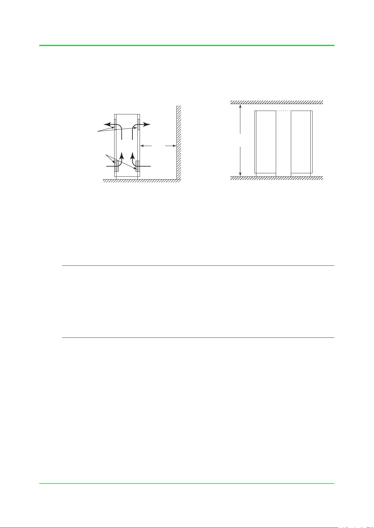
Clearance From The Wall and The Floor Surface
There are ventilation holes on the front and rear doors of the cabinets. To ensure good air
ventilation and easy maintenance, provide a clearance of at least 1000 mm (including the service
areas) from the wall to the front and rear doors of the cabinets. Also make sure the height of the
ceiling is at least 2400 mm from the oor.
Ceiling
Ventilation
holes
Side of
Cabinet
Figure Wall Clearance and Ceiling Height
1000
mm
or
more
2400 mm
or more
Floor surface
Cabinet Cabinet
Illumination
1-3
The illumination level around a display unit should be 700 to 1500 lx (target illumination level:
1000 lx). The illumination level inside the control room should be reasonably uniform.
Select proper light xtures and install them in positions where they don’t cause glare on the CRT
displays and LCDs.
TIP
REFERENCE (Illumination standards):
For ultra-precision work: 1500 to 3000 lx (illumination level: 2000)
For precision work: 700 to 1500 lx (illumination level: 1000)
For ordinary work: 300 to 700 lx (illumination level: 500)
For non-detail work: 150 to 300 lx (illumination level: 200)
Passages, warehouses: 30 to 150 lx (illumination level: 50 to 100)
(Source: JIS Z9110)
Outlets for Maintenance
Outlets (approx. 1.5 kVA) for measurement devices should be provided near the installed
equipment for maintenance.
Telephone
Telephones should be installed for communications with related stations.
TI 32S01J10-01E
Aug. 10, 2011-00
Page 16

1. System Installation Requirements
Air Conditioner
The air conditioner should be operated according to the conditions below to prevent moisture
condensation on the installed equipment.
• Keep changes in temperatures within ±10°C/h.
• Install the air conditioner away from the equipment.
• Install substitute air conditioners to prevent moisture condensation as a result of the
temperature rising or falling if an air conditioner fails.
• Set the air conditioner so that its air outlet is not above the equipment (to avoid water
dropping on the equipment).
Windows
Close the windows of the control room. If a draft comes in around the windows, seal around the
windows.
Opening the window while air conditioning is running may result in condensation forming, or let in
dust or corrosive gas, adversely affecting the installed equipment. Windows on the sea side must
be closed to keep out salt air.
Install blinds, if necessary, to prevent sunlight reecting from CRT displays and LCDs.
1-4
TI 32S01J10-01E
Mar. 21,2005-01
Page 17

1. System Installation Requirements
Acceleration
A: Displacement amplitude (mm)
F010201.ai
1.2 Control Room Environment
This section describes environmental conditions of the control room to operate the
system safely, and stably over a long period of time.
It is recommended that user have the control room environment assessment. For the
assessment, contact Yokogawa if necessary.
Temperature and Humidity Limits
SEE
See “Table of Equipment Installation Specications” in this section, for the temperatures and humidity limits for
ALSO
operating and storing this equipment.
When bringing the equipment into a location where allowable operating temperature is set
from another location where the temperature exceeds the allowable operating range, following
precautions are necessary:
• The equipment should reach the ambient temperature according to the requirements for the
temperature change rate, keeping it unpacked from its case. At that time, be careful not to
let condensation form on the equipment.
1-5
• Once the equipment reaches the allowable operating temperature range, leave it for about
three hours before operation.
Under normal operation, the rate of change of ambient temperatures should be within 10°C/h. All
the equipment should be kept out of direct sunlight.
Condensation
Prevent condensation. If condensation occurs, or its trace is found on the control room, contact
Yokogawa.
SEE
See “Section 2.3 Storage” for more information.
ALSO
Vibration
Vibration in the control room should be limited as follows:
• For vibration frequency up to 8.4 Hz: Limit displacement amplitude to 1.75 mm or less.
• For vibration frequency over 8.4 Hz: Limit acceleration to 4.9 m/s2 or less.
The following is the relationship of the vibration frequency, displacement amplitude, and
acceleration:
(m/s2) = 4π2 • A • F2 • 10
-3
F: Frequency (Hz)
Consult Yokogawa if complex vibrations are involved.
TI 32S01J10-01E
Dec. 1, 2011-00
Page 18

1. System Installation Requirements
E
E : Electric field strength (V/m)
F010202.ai
Air Purity
The dust in the control room should be kept below 0.3 mg/m3. Minimize corrosive gas such as
hydrogen sulde (H
and carbon.
2
S), sulfur dioxide (SO2), chlorine, and conductive dust such as iron powder
1-6
The allowable content of H
2
S, SO2, or any other corrosive gas varies with temperatures, humidity,
or existence of other corrosive gas. Consult Yokogawa if corrosive gas exists.
Magnetic Field
Do not install the CRT near cables with heavy current owing or in the magnetic eld of a power
supply. If installed in such locations, the display may be distorted or its colors may be affected by
the magnetic elds.
Electric Field Strength (Electric Wave Condition)
For the proper and stable operation of this system, the eld electric strength of the location for the
equipment should be controlled as following:
10 V/m or less (26 MHz to 1.0 GHz)
10 V/m or less (1.4 to 2.0 GHz)
1 V/m or less (2.0 to 2.7 GHz)
In case of the usage of wireless equipment such as transceiver nearby this system, note as
following:
• The door of this system should be closed.
• In case of the usage of transceiver with 10 W or less, the distance from this system should
be kept 1 m or more.
• As for the usage of wireless equipment with 1 W or less such as mobile-telephone, PHS,
wireless telephone or LAN equipment, the distance should be kept 1 m or more. Attention
should be paid to the micro wave radiated from mobile-telephone or PHS even out of usage.
Following formula represents the electric eld strength. However, the calculated value requests
ideal environment. Worse conditioned environment should be taken into consideration. In case
some wireless equipment is used nearby this system, this formula would be useless. The value
calculated through this formula should be considered noting other than reference.
k P
=
d
k : Coefficient (0.45 to 3.35; average 3.0)
P : Radiation power (W)
d : Distance (m)
TI 32S01J10-01E
Jan.21,2010-01
Page 19
1. System Installation Requirements
Installation Specication
Installation height: Altitude of up to 2000 m
Installation category based on IEC 61010-1 (*1)
Category I
• For YOKOGAWA products, category I applies to the device that receives the electric power
not more than 33 V AC, 70 V DC.
Category II
• For YOKOGAWA products, category II applies to the device that receives the electric power
exceeding 33 V AC or 70 V DC.
Pollution degree based on IEC 61010-1: 2 (*2)
*1: The installation category, also referred to as an overvoltage category, denes the standard for impulse voltage. The category
number from I to IV applies the devices to determine the clearance required by this standard.
Category I applies to the device intended to be connected to a power supply with impulse voltage reduced to the safe level.
Category II applies to the device intended to be supplied from the building wiring.
*2: Pollution degree indicates the adhesion level of foreign matter in a solid, liquid, or gaseous state that can reduce dielectric
strength. Degree 2 refers to a pollution level equivalent to the general indoor environment.
SEE
See “Installation Environment Specications” at the end of this chapter.
ALSO
1-7
Measurement Categories
Regarding the measurement inputs, the following requirements must be satised to meet the
specications for the device:
The category of the equipment applies to No.1 in the following table.
The rated transient overvoltage is 1500 V.
Note: Do not use the equipment for measurements within measurement categories II, III and IV.
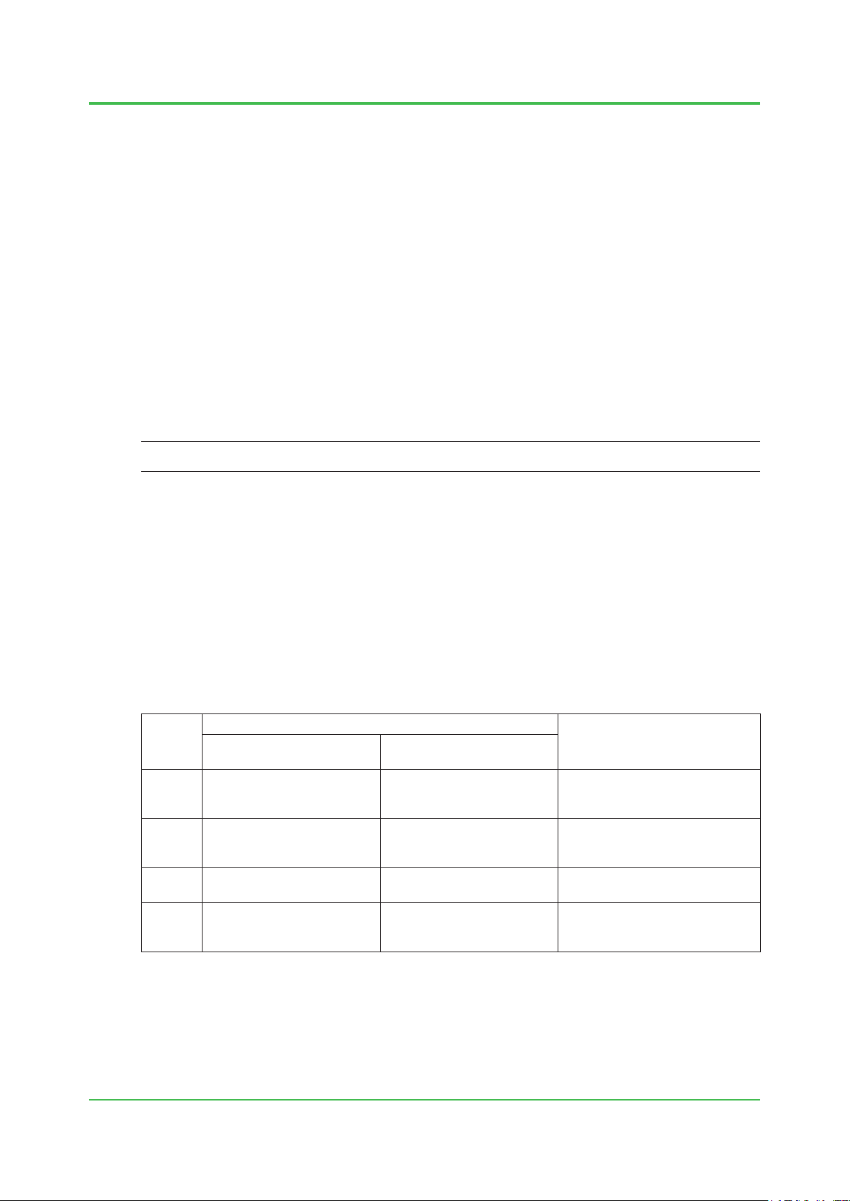
Table Measurement category
Applicable Standard
No.
No.1 Measurement category I O (Other)
No.2 Measurement category II Measurement category II
No.3 Measurement category III Measurement category III
No.4 Measurement category IV Measurement category IV
IEC/EN/CSA
61010-1:2001
EN 61010-2-030
Description
For measurements performed on
circuits not directly connected to
MAINS.
For measurements performed on
circuits directly connected to the
low voltage installation.
For measurements performed in
the building installation.
For measurements performed
at the source of the low-voltage
installation.
TI 32S01J10-01E
Aug. 31, 2015-00
Page 20

1. System Installation Requirements
Applied Standards
The ProSafe-RS complies with the standards shown below.
IMPORTANT
Different standards are applied according to the types of equipment.
For details, refer to the hardware General Specications (GS) for each equipment.
Functional Safety Standards
IEC 61508, IEC 61511-1 and IEC 62061
Standard for Programmable Controllers (*1), (*2), (*3)
IEC 61131-2
Applicable Standards (*1)
1-8
EN 54-2 (*5), EN 298 (*3), (*4), EN 50156-1, NFPA 85, NFPA 72
Safety Standards (*6), (*8), (*9), (*10)
[CSA]
CAN/CSA-C22.2 No.61010-1 (100-120 V AC power supply)
[CE Marking] Low Voltage Directive
EN 61010-1, EN 61010-2-201, EN 61010-2-030, EN 60825-1 (100-120 V AC (*7), 220-240 V AC
and 24 V DC power supply)
[EAC Marking]
CU TR 004
*1: A lightening arrester or the like is required to meet this surge immunity standard.
*2: 24 V DC and 48 V DC eld power cables to DI and DO should be a maximum of 30 m in length.
*3: Where the system power uses 24 V DC (SPW484), use an external uninterruptible power supply (UPS).
*4: 24 V DC and 48 V DC eld power cables to DI and DO should be a maximum of 10 m in length.
*5: A clamp lter (A1193MN) should be connected to the V net cable.
*6: For the rack mountable devices, DIN rail mountable devices, and wall mountable devices to meet the Safety Standards and EMC
Standards, the devices must be installed in a lockable metal cabinet. The cabinet must conform to IEC/EN/CSA 61010-2-201 or
provide degrees of protection IP3X or above and IK09 or above.
*7: SSC10-211 does not comply with CE Marking of 100 V AC.
*8: Measurement inputs of this equipment are applied to Measurement category I for IEC/EN/CSA 61010-1:2001 and O (Other) for
EN 61010-2-030.
*9: For ensuring all the hardware devices to satisfythe safety standards, the dedicated breakers in the power supply distribution
board must conform to the following specications.
[CSA] CSA C22.2 No.5 or UL 489
[CE Marking] EN 60947-1 and EN 60947-3
[EAC Marking] EN 60947-1 and EN 60947-3
*10: The ground suitable for the power distribution system in the country or region has to be used for protective grounding system.
TI 32S01J10-01E
Aug. 31, 2015-00
Page 21

1. System Installation Requirements
EMC Conformity Standards (*2), (*3)
[CE Marking] EMC Directive
EN 55011 Class A Group1 (100-120 V AC (*4), 220-240 V AC and 24 V DC power supply) (*5)
EN 61000-6-2 (100-120 V AC (*4), 220-240 V AC and 24 V DC power supply) (*1)
EN 61000-3-2 (220-240 V AC power supply) (*6)
EN 61000-3-3 (220-240 V AC power supply)
[RCM]
EN 55011 Class A Group1 (220-240 V AC and 24 V DC power supply) (*5)
[KC Marking] (100-120 V AC (*4), 220-240 V AC and 24 V DC power supply)
Korea Electromagnetic Conformity Standard
[EAC Marking]
CU TR 020
[Functional Safety]
IEC 61326-3-1
*1: A lightening arrester or the like is required to meet this surge immunity standard.
*2: 24 V DC and 48 V DC eld power cables to DI and DO should be a maximum of 30 m in length.
*3: For the rack mountable devices, DIN rail mountable devices, and wall mountable devices to meet the Safety Standards and EMC
Standards, the devices must be installed in a lockable metal cabinet. The cabinet must conform to IEC/EN/CSA 61010-2-201 or
provide degrees of protection IP3X or above and IK09 or above.
*4: SSC10-211 does not comply with CE Marking and KC Marking of 100 V AC.
*5: The analog inputs of this system fall into Measurement Category I of IEC 61010-1.
*6: A Class A hardware device is designed for use in the industrial environment. Please use this device in the industrial environment
only.
1-9
Standard for Hazardous (Classied) Locations
[FM Non-Incendive]
[Type “n”]
SEE
For more information about Standard for Hazardous Locations, refer to TI 32S01J30-01E “Explosion Protection
ALSO
(for ProSafe-RS).”
Marine Standards
ABS (American Bureau of Shipping)
BV (Bureau Veritas)
Lloyd’s Register
SEE
For more information about the components which comply with the marine standards and how to install those
ALSO
components, refer to 1.8, “Compliance with Marine Standards.”
In relation to the CE Marking, the manufacturer and the authorised representative for ProSafeRS in the EEA are indicated below:
Manufacturer: YOKOGAWA Electric Corporation
(2-9-32 Nakacho, Musashino-shi, Tokyo 180-8750, Japan.)
Authorised representative in the EEA: Yokogawa Europe B.V.
(Euroweg 2, 3825 HD Amersfoort, The Netherlands.)
TI 32S01J10-01E
Aug. 31, 2015-00
Page 22

1. System Installation Requirements
1-10
Installation Environment Specications
The following table lists environmental requirements for the installation of the ProSafe-RS
System.
SEE
For details on each equipment, refer to the ProSafe-RS general specications (GS).
ALSO
Table Installation Environment Specications
Item Specications Remarks
–20 to 50°C (basic safety control unit for V net)
–20 to 40°C (basic safety control unit for Vnet/IP)
–20 to 70°C (temperature-adaptive safety control
Temperature
Normal operation
unit and safety node unit)
Transportation/storage –40 to 85°C
Normal operation 5 to 95% RH (non-condensing)
Humidity
Temperature
change
Transportation/storage 5 to 95% RH (non-condensing)
During operation Within ± 10ºC/h
Transportation/storage Within ± 20ºC/h
100 to 120 V AC –15%, +10%
Voltage range
220 to 240 V AC –15%, +10%
24 V DC: –10% to +20%
Frequency 50/60 Hz ± 3Hz
Power supply
Distortion factor 10% or less
Crest factor
100 V system: 118 V or larger
220 V system : 258 V or larger
Momentary failure 20 ms or less (when receiving the rated AC voltage)
DC power supply ripple rate 1% p-p maximum
1500 V AC for 1 minute
Withstanding voltage
(for 100-120/220-240 V AC)
500 V AC for 1 minute
(for 24 V DC)
Insulation resistance 20 M ohms at 500 V DC
Apply the grounding system which is dened
Grounding
by the rules and standards of the country or the
region.
Dust Maximum of 0.3 mg/m
3
Corrosive gas ANSI/ISA S71.04 G3 (standard)
Electric eld 10 V/m maximum (80 MHz to 1 GHz)
Noise
Static electricity
Continuous vibration
Vibration
Non-continuous vibration
Seismic Acceleration: 4.9 m/s
Transportation
Impact 147 m/s
4 kV or less (direct discharge)
8 kV or less (aerial discharge)
Amplitude: 1.75 mm (5 Hz to 9 Hz)
Acceleration: 4.9 m/s
Amplitude: 3.5 mm (5 Hz to 9 Hz)
Acceleration: 9.8 m/s
Horizontal: 4.9 m/s
vertical: 9.8 m/s
2
, 11 ms
2
(9 Hz to 150 Hz)
2
(9 Hz to 150 Hz)
2
or less
2
or less
2
or less
Altitude 2000 m above sea level or less
*1: When ALR111-S1/ALR121-S1 is installed, the ambient temperature should range from 0 to 60 °C. In case of ALR121-SB, it should
range from 0 to 70 °C. When ALE111-S1 is installed, the ambient temperature should range from 0 to 60 °C. ALE111 supported in
R3.02.00 or later can be mounted on SSC60, SSC50 or SSC57.
(*1)
5 to 85 % RH when
the SRM53D/RM54D/
SBM54D is mounted.
Between power &
ground terminals
Between power &
ground terminals
Excluding SRM53D/
SRM54D/SBM54D
When packaged
SEE
For the level of corrosive gases permitted in an ordinary ofce, refer to TI 33Q01J20-01E “Guidelines for
ALSO
Installation Environment.”
TI 32S01J10-01E
Oct. 1, 2014-00
Page 23
1. System Installation Requirements
Peak A
F010301.ai
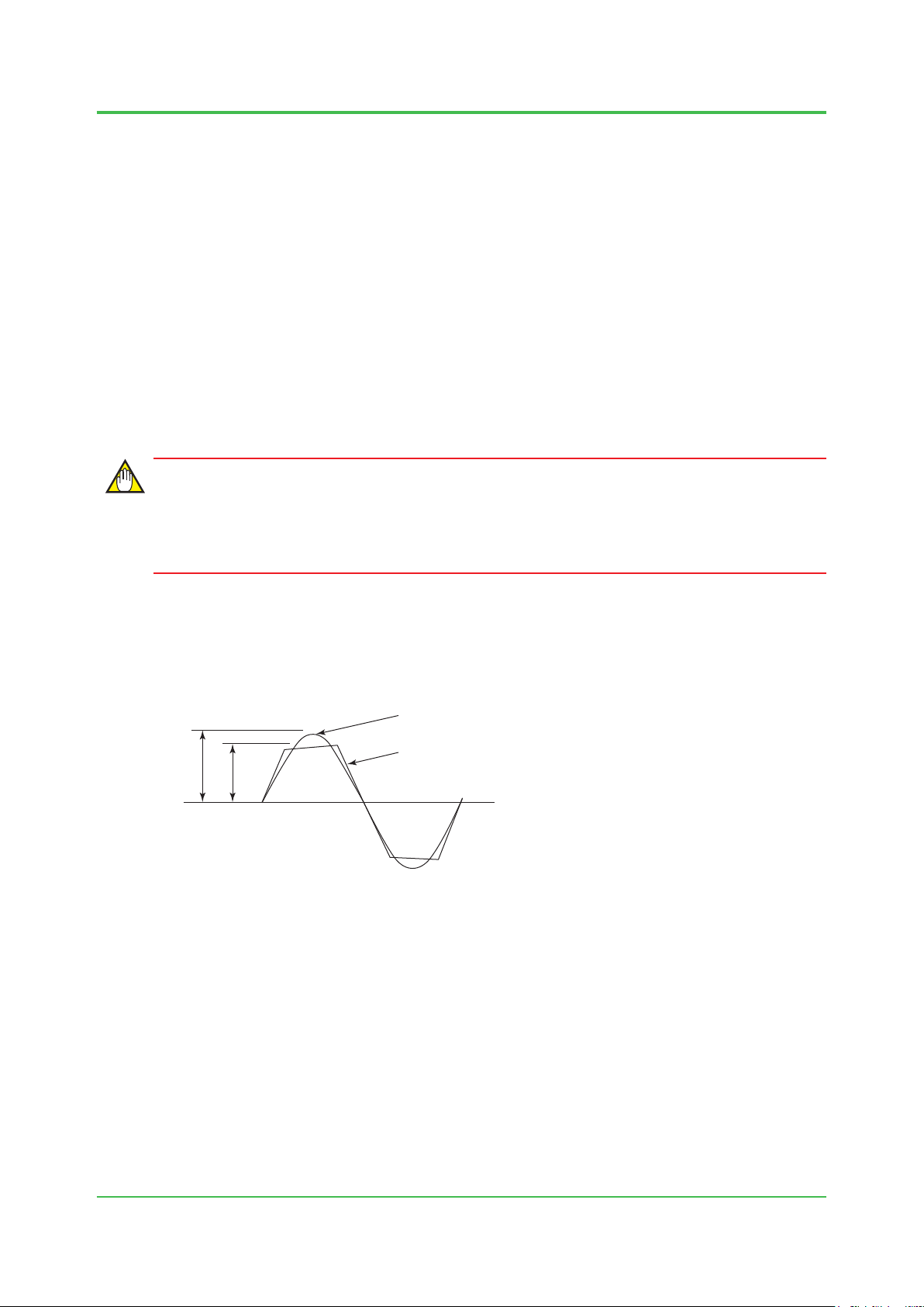
A: Ideal, non-distorted input voltage wave
1.3 Power Supply System
The following conditions should be met:
• Voltage and frequency uctuations are within the limits specied for each system
component.
• Waveform distortion is within limits.
• High-frequency noise is not at a level that affects system operation.
• Use an UPS (uninterruptible power supply) if necessary.
AC Power Specication
AC power used for the system must be within the specied rated voltage and the peak value
must be greater than the minimum specied (see below). DC power must be within 24 V DC
-10%/+20% at the power supply terminals.
IMPORTANT
If the power unit has high output impedance or high wiring impedance, the resulting voltage drop
attens the input voltage wave, forming a distorted waveform with a low peak value (“B” in the
chart below).
1-11
Even if the effective value of the distorted input voltage wave is the same as that specied for a
non-distorted input voltage wave, the voltage across the terminals of the smoothing capacitor
in the power circuit may be so low that the system detects power failure. Even if input voltage
waves A and B shown below have the same effective value of 100 V AC, wave B will have a
lower smoothing capacitor terminal voltage.
B: Distorted input voltage wave
Peak B
Figure Distorted Input Voltage Waveform
TI 32S01J10-01E
Jun. 30, 2011-01
Page 24
1. System Installation Requirements
V
V
V
Effective
F010302.ai
F010303.ai
Power/failure
Smoothing capacitor
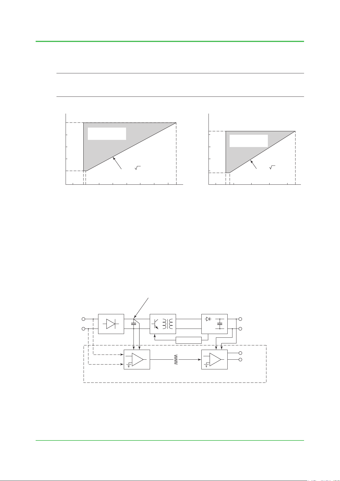
The system operating voltage range is shown below based on the relationship between effective
and peak values at the power input terminal of each system. Apply AC power within these ranges
to operate the system.
TIP
Average-value rectifying measuring instruments such as general type digital voltmeters and testers cannot
measure effective values accurately. Use Yokogawa’s digital oscilloscope DL series, power analyzer WT series or
equivalent device, which can measure effective values, peak values, and waveform distortion.
132
value
(V rms)
120
110
100
85
System operating
voltage range
Effective
V op= 2 V rms
value
(V rms)
264
240
220
200
187
System operating
voltage range
1-12
V op= 2 V rms
110
118 120
130 140 150 170
Peak value (V op)
160
180
187
V
258 264
240 330 360
270 300
Peak value (V op)
374
Figure System Operating Voltage Range
The DC stabilized power supply for the ProSafe-RS (except PCs) uses a compact and efcient
switching regulator circuit. In this circuit, output voltage cannot be maintained if the energy
(terminal potential) of the smoothing capacitor falls below a predetermined value. The circuit
monitors the capacitor terminal voltage and regards it as power failure if the voltage falls in the
danger zone, causing the system to enter power fail mode (non-detected momentary power
failure: up to 20 ms).
Current ows to the capacitor in this circuit when AC input voltage is higher than the capacitor
terminal voltage. Since the capacitor is charged by the peak value of the input waveform, it is
required that both the effective voltage value and the peak value conform to the specication
requirements.
Rectification, smoothing,
power factor correction
Input
(AC)
control
(Waveform
monitoring)
Figure Power Circuit Diagram of Safety Control Unit
Input voltage
monitoring
terminal voltage
DC/AC Rectification
PWM
Insulation
Output voltage
monitoring
ACRDY
DCRDY
Output
(DC)
System
control
signal
TI 32S01J10-01E
Jun. 30, 2011-00
Page 25

1. System Installation Requirements
Selecting a Power System
The ProSafe-RS system requires a power supply that satises power requirements in
accordance with EMC regulations. It is recommended that an external power supply unit be
used in order to prevent disruptions due to momentary or extended power failure, line noise, or
lightening surges, as well as to suppress harmonic current from various devices.
For selection of the power supply unit, consult with a power unit manufacturer taking the following
points into consideration.
Source Output Capacity
Take the following items into consideration when consulting with a power unit manufacturer to
determine the output capacity.
Power consumption: Both volt-ampere and watt data should be studied.
Device crest factor: Ratio of the peak value to the effective value of the device input
current.
Device in-rush current: The method of turning on the power should also be studied.
Backup ready time after failure: Time period required to backup the devices when power fails.
Reserve capacity: An extra power capacity should be determined as reserve to
meet any device additions.
1-13
SEE
ALSO
• Electrical Specications Table for power consumption in Chapter 4
• In-rush Current of Each Component in Chapter 4
TI 32S01J10-01E
Jun.18,2008-01
Page 26
1. System Installation Requirements
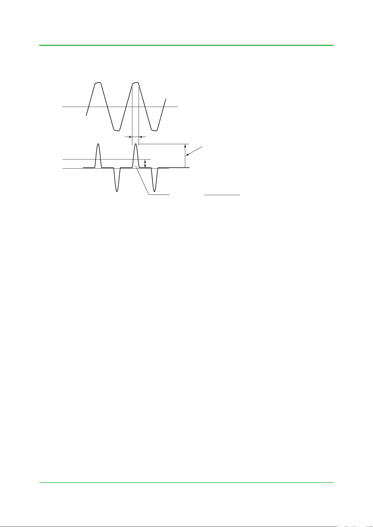
F010304.ai
Input voltage waveform
Crest factor
The crest factor is the ratio of the peak value to the effective value of the device input current.
1-14
Input current waveform
Figure Input Voltage and Input Current Waveforms
Approx. 5 ms
Effective value
Crest factor =
Peak value
Peak value
Effective value
Crest factor = Peak value of device input current / Effective value of device input current
The crest factor must be considered for the input current supplied to every device connected to
the system when estimating the power output capacity in selecting the power unit.
Approximate device crest factors should be as follows:
100-120 V supply voltage: Crest factor About 3.
220-240 V supply voltage: Crest factor About 6.
Common Method to Determine Power Unit Capacity
The following shows the commonly used method used to determine the power unit capacity
taking the crest factor into consideration - the nal determination should be made in consultation
with a power unit manufacturer:
• If the specication of power unit crest factor (the peak current value allowable for the
effective current value) is larger than the above device crest factor, the power unit can be
used for up to full rated capacity. However, in-rush current, backup time, reserve capacity,
etc., must be separately taken into consideration.
• If the power unit crest factor is smaller than the device crest factor, the power unit capacity
needs to be calculated in the expression shown below. In-rush current, backup time, reserve
capacity, etc., must be separately taken into consideration.
Power unit output capacity = Total device power consumption x Capacity coefcient
Capacity coefcient = Device crest factor / Power unit crest factor specication
TI 32S01J10-01E
Jun.18,2008-01
Page 27

1. System Installation Requirements
In-Rush Current
When the equipment is turned on, a large in-rush current ows as the capacitor is
instantaneously charged and the transformer is excited. When any equipment is turned on, this
should not cause any voltage uctuation that could adversely affect other equipment. Do not turn
on all equipment at the same time. Start equipment one by one.
Power may be switched to backup or AC line power if in-rush current activates the overload
protection circuit on power-up. After such an overload, select an uninterruptible power unit, with
automatic-recovery.
Suppressing Harmonic Current
In order to suppress harmonic current supplied to a low-voltage distribution system, it is
necessary to install a power unit or an active harmonic suppressor, such as indicated below,
between a device and the distribution system:
• Power unit equipped with the harmonic suppression function (a high power-factor inverter-
type uninterruptible power unit, etc.)
• Active harmonic suppressor
In Europe, a power unit should be selected so that harmonic current emissions are within the
limits specied by EMC regulations.
The capacity of the harmonic suppression unit should be determined in consultation with a power
unit manufacturer in the same manner as the selection of power unit’s output capacity previously
discussed.
1-15
Cabling
Observe the following when cabling the power unit to the ProSafe-RS system equipment:
• Protect signal cables from induced noise.
• Protect signal cables from induction from high-voltage power lines.
• Separate the ProSafe-RS system power supply from other equipment power supplies.
• Provide a dedicated breaker for each power supply.
• Install breakers and devices in the same room.
• Label the breakers with the name of the connected equipment.
• Install the breakers where they can be easily operated.
• The breaker, must not interrupt connection by wiring to protective grounding system.
• As far as possible install power supply cables and high-voltage power lines in metallic
• Use shielded cables if metallic conduits cannot be provided.
Use a separate power distribution board.
conduits.
TI 32S01J10-01E
Aug. 31, 2015-00
Page 28

1. System Installation Requirements
1.4 Grounding
To avoid electric shocks and minimize the inuences of external noise, the installed
devices must be grounded to the protective grounding system which complies with the
safety standards, the electrical installations standard, and the power distribution system
of the country or the region.
As for the protective grounding systems, the meshed grounding systems described in
IEC 60364, IEC 62305 and IEC 61000-5-2 can be applied.
A protective device is to be installed in compliance with the rules and regulations, in order
to prevent electric shocks caused by a ground fault.
A plug type power cable has to be connected to the receptacle connected to the protective
grounding system.
1-16
TI 32S01J10-01E
Oct. 1, 2014-00
Page 29
1. System Installation Requirements
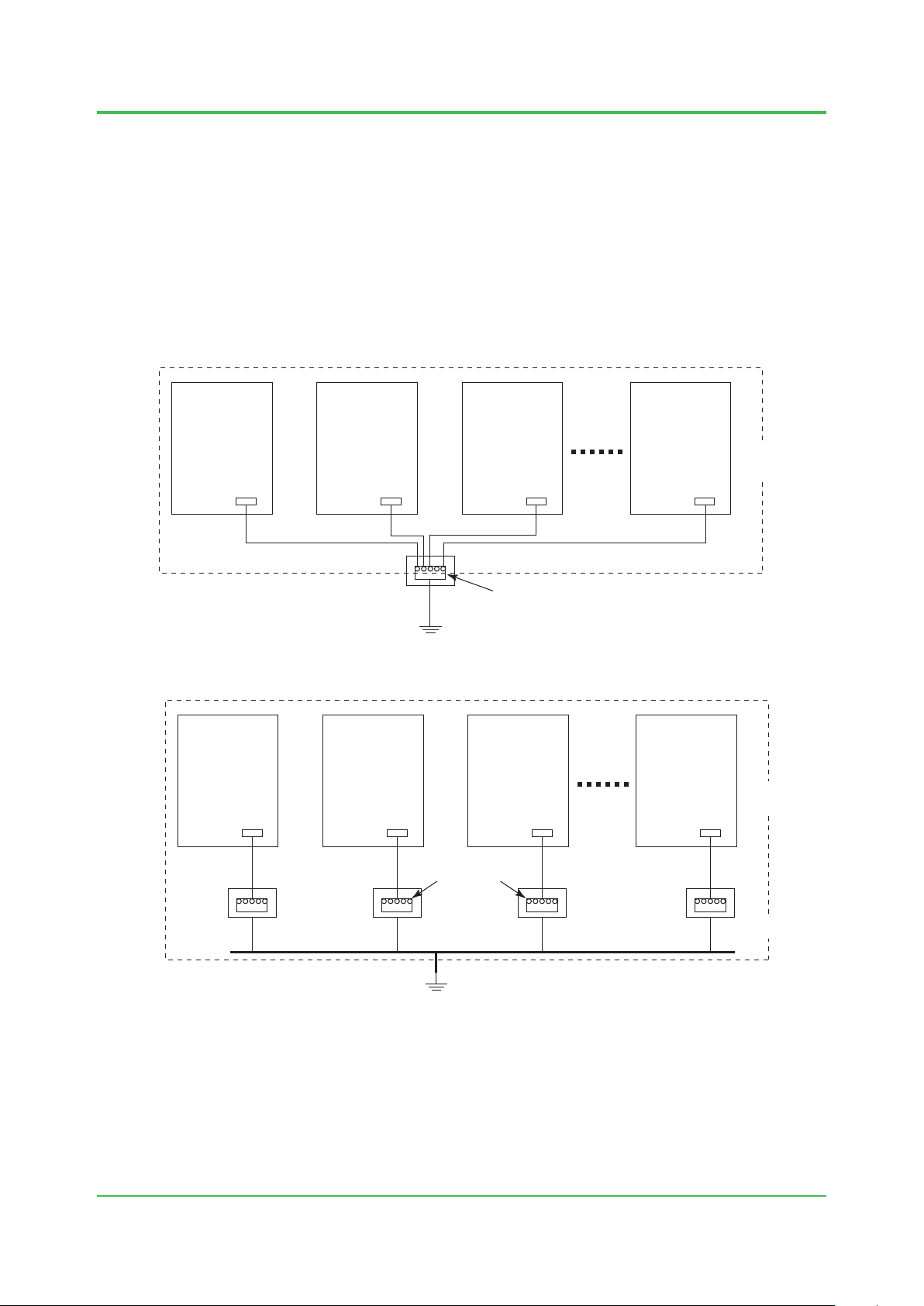
Grounding Circuit
Grounding examples are given below.
If ProSafe-RS systems are housed in a cabinet, the cabinet must be grounded according to the
grounding network topology of the building or plant for installation.
In order to connect a cabinet with a protective grounding system, the grounding topology shown
in the gures “Grounding connected to a single grounding bus inlet” or “Grounding connected to
each grounding bus inlet” can be used.
When providing lightning arresters on power and signal lines, those arresters need to be
grounded to the same bus. For details, see Section 1.5, “Noise Countermeasures.”
Cabinet Cabinet Cabinet Cabinet
G G G G
1-17
In same
control room
Grounding bus inlet
G: Grounding Bar
Protective grounding system
Figure Grounding connected to a single grounding bus inlet
Cabinet Cabinet Cabinet Cabinet
G G G G
Grounding bus inlet
Protective grounding
system
G: Grounding Bar Protective grounding system
Protective grounding
system
Protective grounding
system
Figure Grounding connected to each grounding bus inlet
F010401.ai
In same
control room
Protective grounding
system
F010402.ai
TI 32S01J10-01E
Oct. 1, 2014-00
Page 30
1. System Installation Requirements
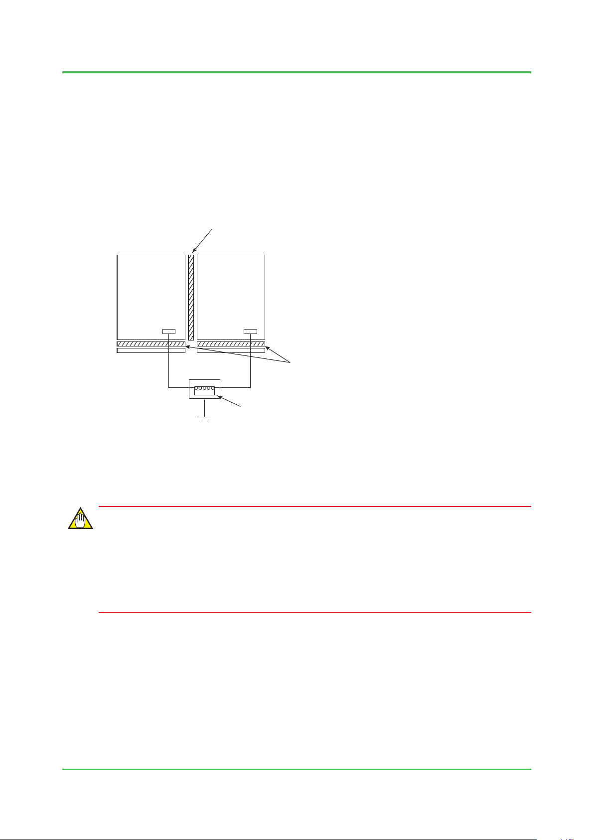
Grounding with Other System
Do not connect ProSafe-RS’s cabinet with other system cabinets or consoles electrically using
bolts or other connection mechanism in order to avoid unexpected electrical connection or
interference.
When ProSafe-RS is joining side by side with other system cabinets or consoles, ensure to insert
insulating sheets.
The cabinets or consoles other than ProSafe-RS must be insulated from a oor and connect it to
a protective grounding system using a different grounding cable.
CENTUM VP can be treated as the ProSafe-RS system in this page.
Insulating sheet
1-18
ProSafe-RS
Cabinet Cabinet
G
G: Grounding Bar
Figure Grounding Using Insulating Sheets
Other system
Equipmment
/Console Type
G
Grounding bus inlte
Protective grounding system
IMPORTANT
Insulating sheet material:
Thickness:
Insulating sheet
PVC or
PL-PEV, PL-PEM Bakelite
5-10 mm
F010404.ai
Do not install the following systems side-by-side with ProSafe-RS:
• Systems using power supply voltages over 300 V AC.
• Systems with current consumption over 50 A.
• System containing high frequency sources.
TI 32S01J10-01E
Oct. 1, 2014-00
Page 31

1. System Installation Requirements
1.5 Noise Countermeasures
Noise may be induced by electromagnetic induction, electrostatic induction, or come
from radio waves, lightning, inductive loads, static electricity and ground potential
differences.
It can be picked up by power, signal and ground cables, and devices. With computerized
control systems, noise-induced errors in A/D conversion or in an instruction word may
lead to malfunction. Therefore, it is necessary to prevent the noise from being generated
or coming too much from the outside.
To prevent noise and electrostatic buildup, take the measures described in this section
when deciding cable type, cable routing, and grounding.
1-19
TI 32S01J10-01E
Oct. 1, 2014-00
Page 32

1. System Installation Requirements
1.5.1 Noise Sources and Noise Countermeasures
It is not easy to identify the cause of any noise-triggered errors or failures due to their lack of
reproducibility.
To prevent noise generation, it is necessary to consider the installation environments such as the
external cable routing, cable types, and grounding.
The following table lists typical noise sources, symptoms of noise problems, and preventive
countermeasures:
Table Noise Sources & Countermeasures
Noise sources Effects Countermeasures
• Maintain separation from magnetic-eld
source.
• Shield power cables with metallic conduits.
• Shield magnetic eld using ferromagnetic
substance (e.g. Permalloy). Or use LCD.
• Use twisted-pair cables.
• Use shielded signal cables.
• Electrically separate power and signal cables
using metallic conduits and separators.
• Lay power and signal cables which intersect at
right angles.
• Lay cables underground.
• Use optical ber cables.
• Lay cables as close to ground as possible if the
cables cannot be laid underground.
• Install and ground arresters on eld and
system.
• Discharge static electricity from operators.
• Provide proper humidity.
• Ground equipment properly.
• Use antistatic oor material and clothing.
• Add spark-killer to noise source.
• Separate laying of cables.
• Keep at least 1 m away from devices to use
a transceiver or a PHS or a cellular phone
(max. output is 1W).
• Avoid multipoint grounding of signal cable.
Electromagnetic induction
(magnetic eld)
Electrostatic induction
Lightning
Electrostatic discharge
Inductive load open/close
Radio (electric eld)
Ground potential difference
• CRT display instability, distortion,
color shift, color fringing.
• Destroys magnetic/exible disk data.
• Equipment maloperation.
• Interference with signals.
• Interference with signals.
• Equipment maloperation.
• Component damage.
• Equipment maloperation.
• Electronic component deterioration,
damage.
• Paper jam.
• Spike noise interference to power
andsignal lines.
• CRT display disruption.
• Equipment maloperation.
• Interference with signals.
• Equipment Maloperation
(noise imposed on signal lines)
1-20
TI 32S01J10-01E
Oct. 1, 2014-00
Page 33

1. System Installation Requirements
Grounding with Lightning Arresters
Connect the protective conductor terminals of arresters and ProSare-RS equipment to the
grounding pole as shown in the diagram below.
The grounding method must comply with the grounding system dened by rules and standards of
the country or the region.
Concatenation grounding a lightning arrester and other equipment may cause high-tension in
each equipment by the product of lightning current from arrester and grounding resistance. To
prevent from electrication, overall connection should be equipotential including the oor and the
case of other equipment.
Shield the cable
Cabinet internal shield ground bar
(with an insulated board)
Connection to grounding bar
Grounding bar for connecting
grounding conductor
1-21
Arrester
To cabinet grounding bar
Apply the grounding system which is defined by
the rules and standards of the country or the region.
Figure Grounding with Lightning Arresters
Cabinet
F010501.ai
TI 32S01J10-01E
Dec. 26, 2014-00
Page 34

1. System Installation Requirements
Examples of Arrester
The following shows how to install an arrester as a countermeasure against lightning-Induced
noise.
1-22
2-wire transmitter
+
2-wire
transmitter
Resistance temperature detector
A
B
B
AR AR
-
Field wiring
AR
Field wiring
Figure Examples of Arrester Installation
AR
System side
Input
module
GND
System side
Input
module
GND
Thermocouple
+
-
Field wiring
Power supply
Field wiring
: Induced lightning strike point
AR: Arrester
AR
AR
Input
module
GND
System side
System
F010502E.ai
モ
ジ
ュ
ー
ル
GND
TI 32S01J10-01E
Oct. 1, 2014-00
Page 35

1. System Installation Requirements
F010503.ai
Examples of Spark-killer Installation
The following shows how to install a spark-killer as a countermeasure against inductive
load-caused noise:
1-23
Relay contact
The spark killer protects relay
contacts from noise occurring when
inductive loads working under AC
operation are turned off.
*1: A diode, which protects the output transistor from noise occurring during
on-to off transition of the relay, is incorporated in the output module except SDV526.
Power supply
The spark killer prevents noisecaused equipment failure when
a fluorescent lamp or fan is
turned on or off.
Example
R: 120 ohms
C: 0.1 to 0.3 μF
Fluorescent
lamp or fan
Example
R: 120 ohms
C: 0.1 μF
Relay
Spark
killer
Spark
killer
Relay
100 V AC
24 V DC
Output
Module
Tr
Controller
control signal
Diode (*1)
ProSafe-RS
Figure Examples of Spark-killer Installation
TI 32S01J10-01E
Oct. 1, 2014-00
Page 36

1. System Installation Requirements
F010504.ai
1 M ohm
Wrist strap
1 M ohm
1.5.2 Countermeasures against Static Electricity
Take countermeasures against electrostatic damage when handling cards with semi-conductor
IC components, for maintenance or to change settings.
Observe the following to prevent electrostatic damage:
• When storing or carrying maintenance parts, keep them in a conductive bag (when
delivered from the factory, they are packed in such bags with labels warning about static
electricity).
• When doing maintenance work, wear a wrist strap connected to a ground wire with a
grounding resistance of 1 M ohm. Be sure to ground the wrist strap.
Conductive sheet
1-24
Grounding resistance
of 1 M ohm
Wrist strap
Connect to earth terminal
or unpainted part of frame
(grounded)
Figure Example of Use of A Wrist Strap and Conductive Sheet
When working with a card with battery
(power supply unit) on a conductive sheet,
set the BATTERY ON/OFF switch to the OFF
position or remove the battery.
• When working on cards: keep conductive sheets, grounded via a resistance of 1 M ohm, on
the work bench. Wear a grounded wrist strap. Remove electrostatic plastics from the work
bench.
• Be sure to wear a wrist strap and use a conductive sheet when handling maintenance parts.
• Wrist straps and conductive sheets are available from Yokogawa.
TI 32S01J10-01E
Oct. 1, 2014-00
Page 37

1. System Installation Requirements
Separator (steel plate)
separate from ProSafe-RS system grounding
F010601.ai
F010602.ai
Signal cables
1.6 Cabling Requirements
The following requirements must be fullled to prevent an equipment malfunction when
laying power and signal cables (these are shielded cables unless specied).
Signal cables used for high-voltage, high-frequency signals (inductive load ON/OFF) must
be separated from other signal cables.
Separator
To prevent an equipment malfunction, provide a separator between power and signal cables as
illustrated below:
1-25
Signal
cables
Figure Separator Used in Duct/Pit
Power
cables
Protective grounding system
Distance between Cables
If a separator cannot be used, keep a distance between signal cables and power cables.
The distances between cables due to operating voltages and currents are shown below.
Table Required Distance between Power & Shielded Signal Cables
Operating voltage Operating current Distance
240 V AC max
240 V AC min
10 A max 150 mm min
10 A min 600 mm min
10 A max 600 mm min
10 A min Cannot be laid together
Figure Distance between Cables under Pit/Free-access Floor
150 mm
or more
Power cables
Signal cables Power cables
150 mm
or more
TI 32S01J10-01E
Oct. 1, 2014-00
Page 38

1. System Installation Requirements
Signal cables
Steel plate (1.6 mm or thicker, grounded)
F010603.ai
Intersecting Cables
With unshielded power cables, place a grounded steel plate with a thickness of at least 1.6 mm
over the cables where they intersect with signal cables.
1-26
Protective grounding system
Figure Intersecting Cables under Pit/Free-access Floor
Ambient Temperature
The ambient temperature where signal and bus cables are laid must be within the limits specied
for each cable.
Measures against EMI
As a rule, avoid laying the cables on the oor. However, lay them on the oor only if there are no
duct and no pit. In that case, it is required to cover them with shield plates or take other measures
to suit the EMC Directive.
Unshielded power cables
TI 32S01J10-01E
Oct. 1, 2014-00
Page 39

1. System Installation Requirements
1.7 Corrosive-gas Environment Compatibility
The ProSafe-RS system complies with the ANSI/ISA G3 environment requirements,
allowing use in a corrosive gas-susceptible environment.
G3 Environment-compatible Products
Table G3 Environment-compatible Products (1/2)
No. Product Model Description
Safety control unit (rack mountable type, for Vnet/IP)
Safety control unit (rack mountable type, for Vnet/IP)
Safety control unit (rack mountable type, for Vnet/IP-Upstream)
Safety control unit (rack mountable type)
1 Node unit
SSC60
SSC50
SSC57
SSC10
SNB10D Safety node unit (rack mountable type)
SAI143-S Analog input module (4 to 20 mA, 16-channel, Module isolation)
1-27
2 Input/output module
ESB Bus Interface
3
Module
Unit for Optical Bus
4
Repeater Module
Optical ESB Bus
5
Repeater Module
SAI143-H
SAV144 Analog input module (1 to 5 V/1 to 10 V, 16-channel, Module isolation)
SAI533
SAT145
SAR145
SDV144
SDV521 Digital output module (24 V DC/2 A, 4-channel, Module isolation)
SDV526 Digital output module (100-120 V AC, 4-channel, Module isolation)
SDV531 Digital output module (24 V DC, 8-channel, Module isolation)
SDV53A Digital output module (48 V DC, 8-channel, Module isolation)
SDV541 Digital output module (24 V DC, 16-channel, Module isolation)
SEC402
SEC401 ESB Bus Coupler Module
SNT10D Unit for Optical Bus Repeater Module
SNT401 Optical ESB Bus Repeater Master Module
SNT501 Optical ESB Bus Repeater Slave Module
SNT411
SNT511
Analog input module (4 to 20 mA, 16-channel, Module isolation,
HART Communication)
Analog output module (4 to 20 mA, 8-channel, Module isolation,
HART Communication)
TC/mV Input Module (16-channel, Isolated Channels)
RTD Input Module (16-channel, Isolated Channels)
Digital input module (no-voltage contact, 16-channel, Module isolation)
ESB Bus Coupler Module (for SSC60, 2-port)
Optical ESB Bus Repeater Master Module 5 km - 50 km
(for SSC60, SSC50, SSC57)
Optical ESB Bus Repeater Slave Module 5 km - 50 km
(for SSC60, SSC50, SSC57)
TI 32S01J10-01E
Oct. 1, 2014-00
Page 40

1. System Installation Requirements
Table G3 Environment-compatible Products (2/2)
No. Product Model Description
ALR111-1
Serial communication module (RS-232C, 2-port)
ALR121-1
Communication
6
module
7 Wiring check adapter
8 Power supply bus unit
ALR121-B
ALR121-3
ALE111-1
ALE111-3
SCB10
AEPV7D-6
AEPV7D-F
AEP7D-6
AEP7D-F
Serial communication module (RS-422/RS-485, 2-port)
Ethernet communication module (*1)
Wiring check adapter for digital input module
Power Supply Bus Unit, Vetical Type
Primary power supply bus unit
SEA4D Analog terminal board (Single and Dual-redundant, 16-channel x 2)
SBA4D
SBT4D
SBR4D
Terminal board for Analog: DIN rail mount type
(Single and Dual-redundant, 16-channel x 1)
Terminal board for TC/mV: DIN rail mount type
(Single and Dual-redundant, 16-channel x 1)
Terminal board for RTD input: DIN rail mount type
(Single and Dual-redundant, 16-channel x 1)
SED2D Digital terminal board (Single and Dual-redundant, 4-channel x 4)
9 Terminal Board
10 Router
*1: ALE111 supported in R3.02.00 or later can be mounted on SSC60, SSC50 or SSC57.
SED3D Digital terminal board (Single and Dual-redundant, 8-channel x 4)
SED4D Digital terminal board (Single and Dual-redundant, 16-channel x 2)
SWD2D
SBD2D
SBD3D
SBD4D
AVR10D-
1
Digital terminal board
(Single and Dual-redundant, 100 to 120 V AC, 4-channel x 4)
Terminal board for Digital output: DIN rail mount type
(Single and Dual-redundant, 4-channel x 1, for SDV521)
Terminal board for Digital output: DIN rail mount type
(Single and Dual-redundant, 8-channel x 1, for SDV53)
Terminal board for Digital: DIN rail mount type
(Single and Dual-redundant, 16-channel x 1, for SDV144/SDV541)
Duplexed V net router
1-28
TI 32S01J10-01E
Dec. 26, 2014-00
Page 41

1. System Installation Requirements
Outline of G3 Environment Compatibility
The classication of the environment in which the process control equipment is installed is
determined by the ANSI/ISA S71.04 “Environmental Conditions for Process Control Systems”
standard. The environment having an atmosphere which contains steams and mists (liquids,
coded L), dusts (solids, coded S), or corrosive gases (gases, coded G) is classied into four
categories according the levels of these substances determined.
The four categories of the corrosive gas environment are dened as follows:
G1 (Mild): A well-controlled environment in which corrosive gas is not the major cause
adversely affecting the reliability of plant equipment. The corrosion level on the
copper test piece is below 0.03 µm (see note below).
G2 (Moderate): An environment in which corrosive gas can be detected and it could be
determined that the gas is the major cause adversely affecting the reliability of
plant equipment. The corrosion level on the copper test piece is below 0.1 µm
(see note below).
G3 (Harsh): An environment in which corrosive gas is frequently generated to cause
corrosion and that it is necessary to provide special measures or employ
specially designed or packaged plant equipment. The corrosion level on the
copper test piece is below 0.2 µm (see note below).
GX (Severe): A corrosive gas-polluted environment that demands special protective chassis
for the plant equipment, specications of which should be seriously determined
by the user and a power unit manufacturer. The corrosion level on the copper
test piece is 0.2 µm or more (see note below).
Note: Copper test pieces are used to determine the level of corrosion for the classication of the plant environment.
The test piece is an oxygen-free copper sheet, which is 15 cm
piece is placed in the plant site for one month and checked for any change before and after the test to determine the degree of
corrosion (see table below). If the test period is shorter than one month, the result is calculated to obtain equivalent data using a
expression dened by the standard.
Table Classication of Corrosive-gas Corrosion Levels
Environment category
Copper corrosion level
G1
(Mild)
< 300
(< 0.03)
2
in area, 0.635 mm in thickness, 1/2 to 3/4H in hardness. The test
G2
(Moderate)
< 1000
(< 0.1)
G3
(Harsh)
< 2000
(< 0.2)
GX
(Severe)
≥ 2000
(≥ 0.2)
1-29
[Å]
( [µm] )
Group A H
Group B HF < 1 < 2 < 10 ≥ 10
Note: The gas density data indicated in the table are for reference only, with the relative humidity of 50% RH or less.
The category goes up one rank higher every time the humidity increases 10% exceeding the 50% RH or over 6% per hour.
S < 3 < 10 < 50 ≥ 50 [mm3/m3]
2
, SO3 < 10 < 100 < 300 ≥ 300
SO
2
< 1 < 2 < 10 ≥ 10
Cl
2
NOx < 50 < 125 < 1250 ≥ 1250
< 500 < 10000 < 25000 ≥ 25000
NH
3
< 2 < 25 < 100 ≥ 100
O
3
The Group-A gases shown in the table may coexist and cause inter-reaction. Inter-reaction
factors are not known for the Group-B gases.
Yokogawa Service Division will carry out environmental diagnosis in accordance with this
standard.
TI 32S01J10-01E
Oct. 1, 2014-00
Page 42

1. System Installation Requirements
1.8 Compliance with Marine Standards
The ProSafe-RS offers compliance with the following marine standards:
• American Bureau of Shipping (ABS)
• Bureau Veritas (BV)
• Lloyd’s Register
This Section introduces the components of systems which comply with the marine
standards, and precautions for installing those components.
Marine Standard-compliant ProSafe-RS Components
The table below shows the ProSafe-RS components which comply with the marine standards.
Table Marine Standard-compliant ProSafe-RS Components (1/3)
Product Model Module Type Description
Including SCP461, SPW481, SPW482
and SPW484.
SSC60S-S and SSC60D-S do not
comply.
Including SCP451, SPW481, SPW482
and SPW484.
Including SCP401, SPW481, SPW482
and SPW484.
Including SSB401, SPW481, SPW482
and SPW484.
(*1)
SAI143-HC does not comply.
Including SCCC01, STB4D, STB4S and
STK4A.
(*1)
(*2)
SDV144-SC does not comply.
SDV521-S3C does not comply.
(*2)
SDV531-L complies with Marine
Standards from style code S3.
SDV531-LC does not comply.
(*2)
SDV541-SC does not comply.
Including SPW481, SPW482 and
SPW484.
Node Unit
Input/Output Module
Wiring Check Adapter
Unit for Optical Bus
Repeater Module
*1: Including SCCC01, STA4D, STA4S and STK4A.
*2: Including SCCC01,SCCC02, STB4D, STB4S and STD4A.
SSC60S-F
SSC60D-F
SSC50S
SSC50D
SSC57S
SSC57D
SSC10S
SSC10D
SNB10D
SAI143
SAV144
SAT145
SAR145
SAI533
SDV144
SDV521
SDV531
SDV53A
SDV541
SDCV01 Dummy cover (for I/O modules)
SCB100
SCB110
SNT10D
Safety control unit
(19 inch rack mountable)
Safety control unit
(19 inch rack mountable)
Safety control unit
(19 inch rack mountable)
Node unit for dual-redundant ESB
bus (19 inch rack mountable)
Analog input module (4 to 20 mA,
16-channel, and module isolation)
Analog input module (1 to 5 V/1 to
10 V and module isolation)
TC/mV Input Module (16-channel,
Isolated Channels)
RTD Input Module (16-channel,
Isolated Channels)
Analog output module (4 to 20 mA,
8-channel and module isolation)
Digital input module (16-channel,
contact input and module isolation)
Digital output module (4-channel,
24 V DC/2A, and module isolation)
Digital output module (8-channel,
24 V DC, and module isolation)
Digital output module (8-channel,
48 V DC, and module isolation)
Digital output module (16-channel,
24 V DC, and module isolation)
Wiring check adapter for digital
input
Unit for optical bus repeater
module
1-30
TI 32S01J10-01E
Oct. 1, 2014-00
Page 43

1. System Installation Requirements
Table Marine Standard-compliant ProSafe-RS Components (2/3)
Product Model Module Type Description
Optical ESB bus repeater master
module
Optical ESB bus repeater master
module 5 km to 50 km
Optical ESB bus repeater slave
module
Optical ESB bus repeater slave
module 5 km to 50 km
ESB bus coupler module
Serial communications module
(RS-232C, 2-port)
Serial communications module
(RS-422/RS-485, 2-port)
(*3)
(*3)
ALR121-SB does not comply.
Optical ESB bus repeater
module
ESB Bus Interface
Module
Communication Module
SNT401
SNT411
SNT501
SNT511
SEC402
SEC401
ALR111
ALR121
ALE111 Ethernet comunication module
SEA4D
SED2D
SED3D
SED4D
Analog terminal board (single and
dual-redundant, 16-channel x 2)
Digital terminal board (single and
dual-redundant, 4-channel x 4)
Digital terminal board (single and
dual-redundant, 8-channel x 4)
Digital terminal board (single and
dual-redundant, 16-channel x 2)
Terminal board for TC/mV: DIN
SBT4D
rail mount type (Single and Dual-
redundant, 16-channel x 1)
Terminal board for RTD input: DIN
SBR4D
rail mount type (Single and Dual-
redundant, 16-channel x 1)
Terminal Board
SBA4D
Terminal board for Analog: DIN
rail mount type (Single and Dual-
redundant, 16-channel x 1)
Terminal board for Digital output:
SBD2D
DIN rail mount type (Single and
Dual-redundant, 4-channel x 1, for
SDV521)
Terminal board for Digital output:
SBD3D
DIN rail mount type (Single and
Dual-redundant, 8-channel x 1, for
SDV53)
Terminal board for Digital: DIN rail
SBD4D
mount type (Single and Dual-
redundant, 16-channel x 1, for
SDV144/SDV541)
SRM53D
SRM54D
Relay Board
SBM54D
8 × 2 dry contact output
(safety relay built-in, M4 terminals)
16 × 1 dry contact output
(safety relay built-in, M4 terminals)
Relay board for Digital output:
DIN rail mount type (Single and
Dual-redundant, 16-channel x 1,
for SDV541)
Control Bus Interface
VI702
VF702 (*4)
VI701
Control bus interface card
(*4)
VF701
Vnet Router AVR10D Duplexed V net router
*3: Only style code S1 complies with Marine Standards.
*4: Noisecut transformer shall be attached in the power-line cable of SENG.
1-31
TI 32S01J10-01E
Dec. 26, 2014-00
Page 44

1. System Installation Requirements
Table Marine Standard-compliant ProSafe-RS Components (3/3)
Product Model Module Type Description
YCB301 ESB bus cable
YCB141 V net cable (10BASE-2)
YCB111 V net cable (10BASE-5)
Cable, etc.
AKB651
AKB331 Signal Cable (50 - 50 pins)
AKB136
AKB161 RS-422/RS-485 cable
AKB611
KS1 Signal cable (40 - 40 pins)
YCB148 V net terminator
YCB146 T-shaped control bus connector
YCB128 Terminator for IRIG (GPS)
Signal Cable (50 - 50 pins) (for
connections between SDV521 and
Terminal Board)
RS-232C null modem cable (9 - 25
pins)
Signal cable (for connections
between SAR145 and Terminal
Board)
When AKB651 is connected to
SDV531-L, SDV53A or SDV541,
it does not comply.
Precaution on Selecting System Components
1-32
When building a system, use components which have already obtained type approval for marine
standards. For the SENG and HISs too, use generic computers (including monitors, keyboards,
mice, and other peripheral devices) which are accredited by the required marine standards.
Precaution on Installing Components
Each component shall be installed in accordance with its installation guidance. In addition, all
components related with SSC60-F, SSC50, SSC57, SSC10, SNB10D, SNT10D and
SENG shall be installed in a metal cabinet.
• The cabinets including their doors and side panels must be made of a metal.
• Securely connect the cabinet frames and ground bosses on doors and side panels to each
other to ensure electric contacts.
• Attach noise suppression devices, such as noise lters and ferrite cores, to the cables
connecting each component.
Installation of Power-line Noise Filter
Attach a noise lter on the power line for the following components:
• Safety Control Unit (SSC60-F, SSC50,SSC57, SSC10)
• Safety Node Unit (SNB10D)
• Unit for Optical Bus Repeater Module (SNT10D)
• Safety Control PC (SENG) installed control bus interface (VI702, VF702)
TI 32S01J10-01E
Oct. 1, 2014-00
Page 45

1. System Installation Requirements
F010805.ai
Allowed Not allowed
Power-line for SSC60-F, SSC50, SSC57, SSC10, SNB10D and SNT10D
Attach a noise lter in each power line of SPW48, FAN and external power supply unit.
Alternatively, other devices such as noisecut transformer and insulating transformer can be used
if its characteristic of noise-reducing effects is same as the following equipment.
Noise lter and external power supply unit shall be installed in the same cabinet of the connecting
terminal board for them.
If digital Input/output modules such as SDV144, SDV521, SDV531, SDV53A and SDV541 are
used, power line for an external power shall be separated from the power line of SPW48 and
FAN.
This means that two AC power cables are out from the cabinet.
It is possible to use power tap outside of the cabinet. Please refer to the following gure.
SSC60
/SSC50
SSC60/SSC50
/SSC57/SSC10
/SSC57/SSC10
1-33
External PSU External PSU
Tap
Noise Filter Noise Filter
AC power feed
Tap
Tap
Figure Wiring for AC power cables
The following table shows example of a noise lter.
Category Manufacturer Model no. Power Source
Noise lter
OKAYA Electric Industries Co., LTD SUPH-EX10-ER-6
COSEL Co., LTD NBH-20-432 24 V DC (*1)
AC/DC
SNB10D SNB10D
AC/DC AC/DC AC/DC
Tap
Tap
Noise Filter
AC power feed
Tap
100 - 120 V AC
220 - 240 V AC
*1: For expansion or modication of unit, the existing TDK Lambda PSHN-2020 can also be used.
IMPORTANT
Lay the incoming wires to a noise lter separately from its outgoing wires.
Minimize the wiring to the ground terminals of the noise lters to minimize the impedance.
TI 32S01J10-01E
Oct. 1, 2014-00
Page 46

1. System Installation Requirements
Power-line for SENG
Noisecut transformer shall be installed in the cabinet and attached in the power-line cable of
SENG in case of using VI702, VF702.
The following table shows applicable noisecut transformer.
Table Applicable noisecut transformer
Description Manufacturer Model
Noisecut Transformer DENKENSEIKI
Research Institute CO., Ltd
TAMURA Corporation NRPT-TB0.5 (*2)
*1: Purchase it through distributer.
*2: Sales was terminated. Use NCT-I1 when purchase noisecut transformer newly.
NCT-I1 (*1)
IMPORTANT
Lay the incoming wires to a noisecut transformer separately from its outgoing wires.
Minimize the wiring to the ground terminal of the noisecut transformer to minimize the
impedance.
1-34
Installation of Ferrite Cores for Vnet/IP
Attach ferrite cores on the power cables, the communication cables and the signal cables.
The following table shows the cables to which ferrite cores are to be attached, the models and
quantities of the ferrite cores to be attached, and the locations at which they are to be attached.
Ferrite core is not required if the component is not listed below. See also the gure following the
table for the locations of installation.
Table Cables that Need Ferrite Cores to be Attached to, and Ferrite Core Models and Quantities for
Vnet/IP (1/2)
Component Description
Power supply
Fan
External power
supply (Input side)
SSC60
-F Power module
Power module
SSC50
Power module
SSC57
SNB10D Power module AC/DC power cable ZCAT3035-1330 4 (2)
SNT10D Power module AC/DC power cable ZCAT3035-1330 2 (3)
AVR10D Power module AC/DC power cable ZCAT3035-1330 4 (4)
SSC60
-F Fan unit
-F Fan unit
SSC50
-F Fan unit
SSC57
Power Supply
(SDV531, SDV541)
AC/DC power cable ZCAT3035-1330 3 (1)
AC/DC power cable ZCAT3035-1330 2 –
AC/DC power cable ZCAT3035-1330 2 –
AC/DC power cable ZCAT3035-1330 3 (5)
AC/DC power cable ZCAT3035-1330 2 –
AC/DC power cable ZCAT3035-1330 2 –
AC power cable
(Input side)
Ferrite Core
Model (*1)
ZCAT3035-1330 1 (6)
ZCAT2032-0930 1
Quantity
Location
(See the
Figures)
*1: The part number of ZCAT3035-1330 is A1179MN, and ZCAT2032-0930 is A1193MN.
Models ZCAT3035-1330 and ZCAT2032-0930 are from TDK Corporation.
TI 32S01J10-01E
Aug. 31, 2015-00
Page 47

1. System Installation Requirements
Table Cables that Need Ferrite Cores to be Attached to, and Ferrite Core Models and Quantities for
Vnet/IP (2/2)
External power
supply (output
side)
Noise lter
(Input side)
Component Description
Power Supply
(SDV531, SDV541)
Power Supply
(SDV521, SDV53A)
DC power cable
(Output side)
DC power cable
(Output side)
Ferrite Core
Model (*1)
ZCAT3035-1330 3 (7)
ZCAT2032-0930 1
ZCAT3035-1330 1
AC power-line lter AC power cable ZCAT3035-1330 1 (8)
ZCAT2032-0930 3
Quantity
ZCAT3035-1330 1 (9)
ESB bus coupler
module
SEC402 ESB bus cable ZCAT3035-1330 5 (10)
SEC401 ESB bus cable ZCAT3035-1330 5 (10)
ZCAT3035-1330 1 (11)
ESB bus interface
module
Optical ESB bus
repeater module
SSB401 ESB bus cable ZCAT3035-1330 4 (12)
ZCAT3035-1330 1 (13)
SNT401 ESB bus cable ZCAT3035-1330 1 (14)
SNT501 ESB bus cable ZCAT3035-1330 1 (15)
CPU SCP461 Vnet/IP cable ZCAT3035-1330 1 (16)
SCP451 Vnet/IP cable ZCAT3035-1330 3 -
Fan unit
SSC60
SSC50
SSC57
-F Fan unit
-F Fan unit
-F Fan unit
Flat cable ZCAT3035-1330 1 - (*2)
Flat cable ZCAT3035-1330 1 - (*2)
Flat cable ZCAT3035-1330 1 - (*2)
Analog module SAI143 KS1 cable ZCAT3035-1330 4 (17)
SAV144
SAI533
Digital module SDV144 AKB331 cable ZCAT3035-1330 3 (18)
SDV521 AKB651 cable ZCAT3035-1330 4
SDV531 AKB331 cable ZCAT3035-1330 3
SDV53A AKB331 cable
ZCAT3035-1330 3
SDV541 AKB331 cable ZCAT3035-1330 3
Terminal board SEA4D KS1 cable ZCAT3035-1330 1 (19)
SED4D AKB331 cable ZCAT3035-1330 1 (20)
Relay board SRM53D AKB331 cable ZCAT3035-1330 3 -
SRM54D
Bus converter VC401 V net cable ZCAT3035-1330 4 (21)
VI451 Vnet/IP cable ZCAT3035-1330 4 (22)
1-35
Location
(See the
Figures)
*1: The part number of ZCAT3035-1330 is A1179MN, and ZCAT2032-0930 is A1193MN.
Models ZCAT3035-1330 and ZCAT2032-0930 are from TDK Corporation.
*2: The component is mounted on the standard model.
TI 32S01J10-01E
Oct. 1, 2014-00
Page 48

1. System Installation Requirements
for HUB
SSC60D-F
(11)
(14)
(14)
SNT401
IOM
IOM
IOM
IOM
SNT401
(11)
(*1) (*1)
(16)
CP U
(16)
CP U
SPW48
SPW48
1-36
(10) (10)
FAN FAN
for SNT501
Cabinet
*1: SEC401/SEC402 ESB Bus Coupler Module
Note: IOM is abbreviation of Input/Output Modules.
Note: Figures in ( ) show the locations listed in "Table Cables that Need Ferrite Cores to be
Attached to, and Ferrite Core Models and Quantities". It is NOT a number of ferrite core.
for SSB401
(5)
(5)
Figure Locations of Ferrite Core Installation for SSC60D-F
(1) (1)
Noise
Filter
(8)
F010809.ai
TI 32S01J10-01E
Oct. 1, 2014-00
Page 49

1. System Installation Requirements
for SEC402/SEC401for SNT401
SNB10D
(12)(12)
1-37
IOM
SNB10D
IOM
IOM
IOM
IOM
IOM
IOM
IOM
IOM
IOM
IOM
for SNT401
IOM
SNT501
SNT501
SNT501
for SSB401
(13)(15)(15)
SNT501
SSB401
(13)
SSB401
SSB401
SSB401
SPW48
(2)(2)
SPW48
(2) (2)
SPW48 SPW48
for SSB401
for SNT401
SNT10D
SPW48
SNT401
SNT401
SNT501
---
Cabinet
- : Empty slot
Note: IOM is abbreviation of Input/Output Modules.
Note: Figures in ( ) show the locations listed in "Table Cables that Need Ferrite Cores to be
Attached to, and Ferrite Core Models and Quantities". It is NOT a number of ferrite core.
---
for SSB401
SNT501
(3)
SPW48
(3)
Figure Locations of Ferrite Core Installation for SNB10D and SNT10D
Noise
Filter
(8)
F010810.ai
TI 32S01J10-01E
Oct. 1, 2014-00
Page 50

1. System Installation Requirements
for SEC402/SEC401
1-38
SNB10D
Field
Device 1
I/O
(20)
Digital
Digital
I/O
(20)
Device 2
Analog
Analog
I/O
I/O
IOM
IOM
IOM
(17)(17)(18)(18)
Terminal Board for Digital I/O / Relay Board
(7)
Field
External
Power
Supply
(12)(12)
SPW48
SPW48
SSB401
SSB401
IOM
(2)(2)
(6)
(19)
(19)
Terminal Board for Analog I/O
Field
Device 3
Field
Device 4
Noise
Filter
Noise
Filter
(8)(9)
Cabinet
Note: IOM is abbreviation of Input/Output Modules.
Note: Figures in ( ) show the locations listed in “Table Cables that Need Ferrite Cores to be
Attached to, and Ferrite Core Models and Quantities”. It is NOT a number of ferrite core.
F010811.ai
Figure Locations of Ferrite Core Installation for Input/Output Modules, Terminal Boards and Relay
Boards
TI 32S01J10-01E
Oct. 1, 2014-00
Page 51

1. System Installation Requirements
for HUB
AVR10D
(22)(22)
1-39
VC401
VI451
VC401
for AIP451
Cabinet
Note: Figures in ( ) show the locations listed in "Table Cables that Need Ferrite Cores to be
Attached to, and Ferrite Core Models and Quantities". It is NOT a number of ferrite core.
VI451
Figure Locations of Ferrite Core Installation for AVR10D
PW44
(4)(21)(21)
PW44
(4)
PDU
Noise
Filter
(8)
F010812.ai
TI 32S01J10-01E
Oct. 1, 2014-00
Page 52

1. System Installation Requirements
Installation of Ferrite Cores for V net
Attach ferrite cores on the power cables, the communication cables and the signal cables.
The following table shows the cables to which ferrite cores are to be attached, the models and
quantities of the ferrite cores to be attached, and the locations at which they are to be attached.
Ferrite core is not required if the component is not listed below. See also the gure following the
table for the locations of installation.
1-40
Table Cables that Need Ferrite Cores to be Attached to, and Ferrite Core Models and Quantities
*1: The part number of ZCAT3035-1330 is A1179MN, and ZCAT2032-0930 is A1193MN.
for V net
Component Description
SSC10 Power Module
Power Supply
Fan
External
power supply
(Input side)
External
power supply
(Output side)
Noise lter
(Input side)
ESB bus
coupler
module
ESB bus
interface
module
ESB bus
interface
module
CPU SCP401 V net coupler cable ZCAT3035-1330 5 (15)
V net coupler
unit
Fan unit
Analog
module
Digital module
Terminal
board
Relay board
Models ZCAT3035-1330 and ZCAT2032-0930 are from TDK Corporation, and the E04SF360270127 is from SEIWA Electric
Mfg. Co., Ltd.
SNB10D Power Module AC/DC power cable ZCAT3035-1330 4 (2)
SNT10D Power Module AC/DC power cable ZCAT3035-1330 2 (3)
SSC10 Fan unit
Power Supply
(SDV531, SDV541)
Power Supply
(SDV531, SDV541)
Power Supply
(SDV521, SDV53A)
AC power-line lter AC power cable
SEC401 ESB bus cable
SSB401 ESB bus cable
SNT401 ESB bus cable ZCAT3035-1330 1 (13)
SNT501 ESB bus cable ZCAT3035-1330 1 (14)
AIP504
SSC10-F Fan unit
Back of SSC10-F
SAI143
SAI533
SDV144 AKB331 cable
SDV521 AKB651 cable 4
SDV531 AKB331 cable 3
SDV53A AKB331 cable 3
SDV541 AKB331 cable 3
SEA4D KS1 cable ZCAT3035-1330 1 (22)
SED4D AKB331 cable ZCAT3035-1330 1 (23)
SRM53D
SRM54D
AC/DC power cable ZCAT3035-1330 2 (1)
AC/DC power cable ZCAT3035-1330 2 (4)
AC power cable
(Input side)
DC power cable
(Output side)
DC power cable
(Output side)
V net coupler cable ZCAT2032-0930 4 (16)
V net cable ZCAT3035-1330 4 (17)
Flat cable ZCAT3035-1330
Flat cable E04SF360270127 1 (19)
KS1 cable ZCAT3035-1330 4 (20)SAV144
AKB331 cable ZCAT3035-1330 3 (23)
Ferrite Core Model
(*1)
ZCAT3035-1330 1
ZCAT2032-0930 1
ZCAT3035-1330 3
ZCAT2032-0930 1
ZCAT3035-1330 1
ZCAT3035-1330 1
ZCAT2032-0930 3
ZCAT3035-1330 1 (8)
ZCAT3035-1330 5 (9)
ZCAT3035-1330 1 (10)
ZCAT3035-1330 4 (11)
ZCAT3035-1330 1 (12)
ZCAT3035-1330
Quantity
1 (18)
3
Location
(5)
(6)
(7)
(21)
(See
Figure)
TI 32S01J10-01E
Oct. 1, 2014-00
Page 53

1. System Installation Requirements
SSC10D-F
(13)(13)
SNT401
SNT401
IOM
IOM
IOM
IOM
(10)(10)
SEC401
(9)
SEC401
(9)
SPW48
CP U
CP U
(15)(15)
SPW48
(1)
(1)
1-41
(16)(16)
AIP504
(17)(17)(17)
(17)
for SSB401
for SNT501
for V net
coupler unit,
VF702,
AVR10D,
etc.
AIP504
Cabinet
Note: IOM is abbreviation of Input/Output modules.
Note: Figures in ( ) show the locations listed in “Table Cables that Need Ferrite Cores
to be Attached to, and Ferrite Core Models and Quantities”. It is NOT a number of
ferrite core.
Figure Locations of Ferrite Core Installation for SSC10D-F
FAN FAN
(4)
(4)
(18)
(19)
Fan Unit
Noise
Filter
(7)
F010806.ai
TI 32S01J10-01E
Oct. 1, 2014-00
Page 54

1. System Installation Requirements
for SEC401for SNT401
SNB10D
(11)(11)
1-42
IOM
SNB10D
IOM
IOM
IOM
IOM
IOM
IOM
IOM
IOM
IOM
IOM
for SNT401
IOM
SNT501
SNT501
SNT501
for SSB401
(12)(14)(14)
SNT501
SSB401
SSB401
(12)
SSB401
SSB401
SPW48
(2)(2)
SPW48
(2) (2)
SPW48 SPW48
for SSB401
for SNT401
SNT10D
SPW48
SNT401
SNT401
SNT501
---
Cabinet
- : Empty slot
Note: IOM is abbreviation of Input/Output modules.
Note: Figures in ( ) show the locations listed in “Table Cables that Need Ferrite Cores
to be Attached to, and Ferrite Core Models and Quantities”. It is NOT a number of
ferrite core.
---
for SSB401
SNT501
(3)
SPW48
(3)
Noise
Filter
(7)
F010807.ai
Figure Locations of Ferrite Core Installation for SNB10D and SNT10D
TI 32S01J10-01E
Oct. 1, 2014-00
Page 55

1. System Installation Requirements
F010808.ai
for SEC401
1-43
SNB10D
Field
device 1
I/O
(23)
(11)(11)
SSB401
Digital
I/O
(23)
I/O
I/O
(20) (20)(21) (21)
IOM
IOM
IOM
Analog
Analog
Digital
SSB401
IOM
SPW48
SPW48
(2)(2)
Terminal Board for Digital I/O
/ Relay Board
(6)
Field
device 2
External
Power
Supply
(5)
(22)
(22)
Terminal Board for Analog I/O
Field
device 3
Field
device 4
Noise
Filter
(8) (7)
Noise
Filter
Cabinet
-: Empty slot
Note:
IOM is abbreviation of Input/Output modules.
Note: Figures in ( ) show the locations listed in “Table Cables that Need Ferrite Cores
to be Attached to, and Ferrite Core Models and Quantities”. It is NOT a number of
ferrite core.
Figure Locations of Ferrite Core Installation for Input/Output Modules, Terminal Boards and Relay
Boards
TI 32S01J10-01E
Oct. 1, 2014-00
Page 56

1. System Installation Requirements
Location of Ferrite Cores for Cables
For the following cables, be careful about the locations at which you install ferrite cores:
Power-line cables:
Install ferrite cores on each cable at the nearest possible place to each connector.
In order to prevent the load at the connectors, secure the power-line cables to the cabinet
frame or dummy plate using cable ties at the nearest possible place to each ferrite core.
ESB bus cables:
Install ferrite cores on each cable at the nearest possible place to each connector.
In order to prevent the load at the connectors, secure the ESB bus cables to the cabinet
frame or dummy plate using cable ties at the nearest possible place to each ferrite core.
Vnet/IP and V net cables:
Install ferrite cores on each cable at the nearest possible place to each connector.
In order to prevent the load at the connectors, secure the Vnet/IP or V net cables to the
cabinet frame or dummy plate using cable ties at the nearest possible place to each ferrite
core.
V net coupler cables:
Install ferrite cores on each cable at the nearest possible place to each connector.
In order to prevent the load at the connectors, secure the V net coupler cables to the cabinet
frame or dummy plate using cable ties at the nearest possible place to each ferrite core.
1-44
Flat cable connecting SSC10-F to its fan unit:
Install ferrite cores on the at cable connecting each SSC10-F to its fan unit. The at cable
needs not be secured.
Cables connected to analog input/output modules and digital input/output modules:
• Cables Connecting to terminal boards or relay boards
Install ferrite cores on each cable at the nearest possible place to each connector.
In order to prevent the load at the connectors, secure the cables to the cabinet frame or
dummy plate using cable ties at the nearest possible place to each ferrite core.
• Vinyl insulated cables used with pressure clamp terminals
Install ferrite cores for all cables. Refer to “Table Cables that Need Ferrite Cores to be
Attached to, and Ferrite Core Models and Quantities” for the number of cores.
It is possible to consolidate multiple cables as per the cable diameter if same ferrite cores
are used for both plus (+) and minus (-) lines.
Signal cables connected to terminal boards or relay boards:
Install ferrite cores on each cable at the nearest possible place to each connector.
In order to prevent the load at the connectors, secure the cables to the cabinet frame or
dummy plate using cable ties at the nearest possible place to each ferrite core.
TI 32S01J10-01E
Oct. 1, 2014-00
Page 57

1. System Installation Requirements
Where a unit component is installed immediately
Top surface
F010802.ai
Installing Unit Components in Cabinet
Unit components here indicate the SSC60-F, SSC50, SSC57, SSC10 and SNB10D node
units and SNT10D unit for optical bus repeater modules. When installing these unit components
in a cabinet, dummy plates may have to be installed and a gasket may have to be attached to the
dummy plates in the following cases:
• There is a large space between unit components.
• There is no space between unit components.
• Unit components are installed unevenly inside the cabinet.
When Leaving a Large Space between Unit Components
When leaving a large space between unit components, install the following dummy plates to
board up the spaces. A UNIT equals 44.45 mm high. Depending on the location of the dummy
plate, attach an EMI shielding gasket to the dummy plate.
Table Space Sizes and Part Numbers of Dummy Plates
Space Size (UNITs in Height) Dummy Plate 1 UNIT = 44.45 mm
1 T9082EX
2 T9933VF
3 T9082EY
6 T9082EZ
1-45
Part number of EMI shielding gasket: G9312AD (1 meter long)
Location to attach EMI shielding gasket:
Attach an EMI shielding gasket onto the bottom surface of the lower bend of a dummy plate as
shown below. Where a unit component is installed immediately above a dummy plate, attach an
EMI shielding gasket also onto the top surface of the upper bend of the plate. However, for the
dummy plate installed at the bottom of the component mounting area, no EMI shielding gasket
needs to be attached onto its lower bend.
above a dummy plate, attach an EMI shielding gasket
also onto the top surface of the upper bend of the plate.
Figure Examples of Installing EMI Shielding Gasket to Dummy Plate
Dummy plate
EMI shielding gasket
Attach onto the bottom surface of the lower bend
of a dummy plate.
TI 32S01J10-01E
Oct. 1, 2014-00
Page 58

1. System Installation Requirements
F010803.ai
F010804.ai
When Installing Unit Components with No Space between Them
When installing two unit components with no space between them, attach an EMI shielding
gasket onto the bottom surface of the lower bend of the upper unit. However, for the unit installed
at the bottom of the component mounting area, no EMI shielding gasket needs to be attached
onto its lower bend.
For the EMI shielding gaskets, use the model introduced in the paragraph under “When Leaving
a Large Space between Unit Components.”
(1)
1-46
EMI shielding gasket
EMI shielding gasket is unnecessary because it is
attached to the unit (1) above.
(2)
EMI shielding gasket
Unnecessary where a dummy plate or unit component is not installed beneath (2).
Figure Examples of Installing EMI Shielding Gasket to Unit Component
When Installing Unit Components Unevenly Inside Cabinet
When installing unit components unevenly and gathering them to the upper or lower part of
a cabinet, leaving a large space in the cabinet, install dummy plates. Attach an EMI shielding
gasket to the dummy plates.
For the EMI shielding gaskets, use the model introduced in the paragraph under “When Leaving
a Large Space between Unit Components.”
SEE
For how to attach EMI shielding gaskets, refer to “When Leaving a Large Space between Unit Components.”
ALSO
(1)
(2)
Dummy plate
Dummy plate
Unit component
Dummy plate
Unit component
Dummy plate
Dummy plate
EMI
shielding
gasket
EMI
shielding
gasket
Dummy plate
Dummy plate
Dummy plate
Dummy plate
Dummy plate
Unit component
Unit component
EMI
shielding
gasket
Figure Example of Installing Dummy Plates and EMI Shielding Gaskets in Cabinet
TI 32S01J10-01E
Unit component
Unit component
Dummy plate
Dummy plate
Dummy plate
Dummy plate
Dummy plate
Oct. 1, 2014-00
Page 59

2. Transportation, Storage and Installation
2. Transportation, Storage and
Installation
This chapter describes the precautions in transporting, storing, and installing the
ProSafe-RS system.
SEE
See Section 1.2, “Control Room Environment” for the environmental requirement for each piece of equipment.
ALSO
2-1
TI 32S01J10-01E
Mar.21,2005-00
Page 60

2. Transportation, Storage and Installation
2.1 Precautions for Transportation
This section describes the precautions required to prevent accidents and damage
when transporting ProSafe-RS system equipment. These precautions apply when the
equipment is contained in our original packing.
Transportation
SEE
For ambient temperature, humidity, vibration and impact, see Section 1.2, “Control Room Environment.”
ALSO
Loading
• Do not load crates on top of others or turn them on their sides.
• Keep all crates upright.
• Secure loaded crates using ropes, and cover them completely with waterproof coverings.
• Do not load crates outdoors when it is raining.
2-2
Don’t Stack Outdoors
Be sure to store cargoes inside a warehouse if they must be stored for some time.
Transportation
Cargoes contain precision instruments. Select a company specializing in the transportation of
computers and precision instruments.
Keep all products upright during air transport, freightage, or truck transport. When transporting by
track, drive at low speed to avoid vibration and impact. Also, slow down to the limit on a bad road.
Others
Do not transport equipment through areas where there may be corrosive gas, intense electric or
magnetic elds.
TI 32S01J10-01E
Mar.21,2005-01
Page 61

2. Transportation, Storage and Installation
2.2 Unpacking
In unpacking the received cargoes and equipment, inspect them according to inspection
list below. It is recommended to unpack by Yokogawa engineers or in their presence.
Table Inspection List
Inspection Items Result Measures Required
• Environment of unpacking location
(temperature, humidity, dust)
Exterior
Interior
*1: Condensation symptoms are as follows:
• Dew patterns on PCBs.
• Printed circuit copper trace is oating off the board.
• Label characters on PCBs are smudged.
• Connectors on PCBs are smudged.
• Dew patterns or traces of droplets are found on cabinet panels.
• Rapid temperature uctuation
(should be within ±10 °C/h)
• Damage to equipment exterior
• Condensation or its trace on
equipment exterior. (*1)
• Loose parts inside equipment.
• Damage to equipment interior.
• Condensation or its trace on
equipment interior. (*1)
Suitable
No
No
No
No
No
No
Unsuitable
Yes
Yes
Yes
Yes
Yes
Yes
If unsuitable, select proper location
according to specied environmental
requirements.
If yes, do not unpack and wait until the
uctuation remains within ± 10 °C/h.
If damaged badly, inform Yokogawa.
If yes, inform Yokogawa.
If yes, remove them and check the
surrounding.
If damaged badly, inform Yokogawa.
If yes, inform Yokogawa.
2-3
IMPORTANT
Condensation may cause a fatal system failure in the ProSafe-RS system. Be sure to unpack
the equipment indoor under the specied environmental conditions. Strictly observe the
allowable temperature uctuation range of ±10 °C/h. Do not bring the equipment into a heated
room straight from the outside in winter. Our warranty does not cover any damage caused by
condensation. Proper treatment may be able to minimize the damage caused by condensation.
Contact Yokogawa in case of condensation.
TI 32S01J10-01E
Mar.21,2005-00
Page 62

2. Transportation, Storage and Installation
2.3 Storage
The delivery date should be determined in accordance with your installation schedule.
Avoid storing products more than three months. If long-term storage more than three
months cannot be avoided, consult Yokogawa in advance because it is necessary to
provide waterproong, condensation prevention, and dustproong measures as well as
periodical inspections.
Storage Condition
Store products without unpacking. Be sure to conrm that the crate is not damaged. To store
them after unpacking, be sure to take the precautions described below.
Location of Storage
Store products in a warehouse or indoor facilities - never in an open-air location.
Storage Environment
• Ambient Temperature for storage: 5 to 40 °C.
2-4
• Avoid direct sunlight.
• Prevent condensation.
• Do not store products where corrosive gas or salty air may be present.
SEE
See “Section 1.2 Control Room Environment” for permissible temperature, humidity and temperature uctuation
ALSO
of storage area.
Storage of Packed Equipment
• Place squared pieces of lumber with a height of 100 mm or higher on the oor. The lumber
should be long enough so that more than 100 mm remains outside of the crate on every
side.
• Securely place unopened crates on the lumber platform.
• Do not stack crates in piles.
• Make sure to provide good air circulation in the storage area and periodically inspect the
crates to keep them under proper conditions.
Storage of Unpacked Equipment
To store unpacked products without power connection, follow the specied environmental
requirements. If stored in a non-air-conditioned room, cover them with polyethylene or other
sheets for protection against dust and moisture. For moisture-proong, place a sufcient amount
of Silica gel or other desiccating agent inside the covering and inspect its effectiveness from time
to time.
TI 32S01J10-01E
Aug. 31, 2015-00
Page 63

2. Transportation, Storage and Installation
2.4 Servicing Area
Take enough space around equipment for its operation and maintenance service.
This servicing area is indicated for each equipment.
The servicing area should be considered in determining the size of installation location.
When installing a number of equipment side by side, take the largest service - area
between them if different dimensions are indicated for different side of equipment, as
indicated below.
Unit: mm
2-5
Good example
800800
800
Figure Servicing Area when Installing Units Side-by-side
SEE
For equipment servicing areas, refer to “External Dimensions” (SD).
ALSO
A
600
Placing another unit on this side
Bad example
800
800
800800
800800
A
600A800
800
600
800800
A
800800
A
600
600
F020401.ai
TI 32S01J10-01E
Oct.1, 2014-00
Page 64

2. Transportation, Storage and Installation
2.5 Installation
Before installation, be sure that anchor bolts, pedestals, and cable holes are provided
according to the customer’s system conguration plans. Check that the positions of
holes on the oor t the anchor bolt holes in the channel base of each piece of equipment.
2-6
TI 32S01J10-01E
Mar.21,2005-00
Page 65

2. Transportation, Storage and Installation
Anchor bolts
F020501.ai
F020502.ai
2.5.1 Installation on Floor
The installation method varies with the type of the oor and building.
• After unpacked, be careful not to put any impact until the equipment is xed to the oor to
prevent it from falling to the oor.
• Install devices as specied in the plans. Check the position of front and back panels of the
cabinet.
Avoid physical shock. Never use hammers.
• Fix each equipment to the oor.
The explanation below shows how to x devices on different types of oors.
Concrete Floor
Clamp the equipment to the oor using anchor bolts. It is recommended to use M12 bolts and
3200 N•cm (320 kgf•cm) tightening torque.
Equipment
2-7
Figure Using Anchor Bolts
Steel Floor
Clamp the equipment to the oor using clamp bolts.
After cabling through the riser duct, ll the duct with rubber sponges and seal the top with putty.
Equipment
Duct
Figure Using Clamp Bolts
Clamp bolt
Steel floor
Riser
TI 32S01J10-01E
Jun.18,2008-01
Page 66

2. Transportation, Storage and Installation
Free-access floor
F020503.ai
Free-access floor supports
F020504.ai
“Free-access” Floor
Clamp the equipment to pedestals that are anchored to the base oor.
Equipment
Pedestal
Base floor
Figure Using Pedestal
In the “free-access” oor, make holes for riser cables to connect to each piece of equipment as
follows:
2-8
• If one oor tile is removed, be sure to reinforce the opening with an angle frame for oor
stability.
Angle frame
Figure Removing One Floor Tile
• Do not make a holes near the oor supports.
• Do not cut away more than 1/3 of a oor tile.
TI 32S01J10-01E
Mar.21,2005-01
Page 67

2. Transportation, Storage and Installation
F020505.ai
IMPORTANT
If a number of neighboring oor tiles are removed, be sure to provide angle frames or pedestals
for reinforcement.
Bad example Good example
Figure Partially Cutting Floor Tile
2-9
TI 32S01J10-01E
Mar.21,2005-00
Page 68

2. Transportation, Storage and Installation
Sealed with putty
F020506.ai
Distribution
F020507.ai
Distribution
Size of Cabling Holes in Floor
For ease of cabling, and for separating power cables from signal cables, it is recommended
that you make holes in the oor for cabling that are the maximum size indicated in the oor
plans. If the specied maximum size hole cannot be provided due to the oor construction or
pit dimensions, the size may be smaller within the range indicated in the plans. If you use the
specied minimum size of hole, use exible cables that can bend inside the channel base.
board
Cabinet
Cabling to rear
Cabling hole
Cabling to front
2-10
Figure Cabling through Maximum Size Hole
board
Cabinet
Sealed with putty
Cabling to rear
Cabling hole
Cabling to front
Figure Cabling through Minimum Size Hole
TI 32S01J10-01E
Mar.21,2005-01
Page 69

2. Transportation, Storage and Installation
2.5.2 Rack Mounting
Rack-mount devices include:
SSC60S, SSC60D, SSC50S and SSC50D Safety Control Units (for Vnet/IP);
SSC57S and SSC57D Safety Control Unit (for Vnet/IP-Upstream)
SSC10S and SSC10D Safety Control Units (for V net);
SNB10D Safety Node Unit;
SNT10D Unit for Optical Bus Repeater Module;
YNT511D, and YNT522D Optical Bus Repeaters;
YNT512D Bus Repeaters;
SEA4D, SED2D, SED3D, SED4D and SWD2D Terminal Board;
SBA4D, SBD2D, SBD3D, and SBD4D Terminal Board (*1);
SRM53D and SRM54D Relay Board;
SBM54D Relay Board (*1);
AEPV7D Power Supply Bus Unit Vertical Type (*2)
AEP7D Primary Power Supply Bus Unit; and
AVR10D Duplexed V net router.
*1: DIN Rail Mount Type
*2: AEPV7D can not be installed to 19-inch Rack.
IMPORTANT
2-11
• To meet the Safety Standards and EMC Standards, the devices must be installed in a
lockable metal cabinet. The cabinet must conform to IEC/EN/CSA 61010-2-201 or provide
degrees of protection IP3X or above and IK09 or above.
• When installing rack mount devices on the same rack, keep 3-unit spacing (1 unit: 44.45 mm)
under a safety control unit. Other units can be installed next to each other with specied
condition.
For more details, see “Providing Space for Heat Radiation”.
Figure Mounting SNB10D Safety Node Unit
TI 32S01J10-01E
F020508.ai
Aug. 31, 2015-00
Page 70

2. Transportation, Storage and Installation
F020509.ai
Notes on Installation
IMPORTANT
For safety during installation, secure an ample working space and work in a team. Be sure to
observe the following when installing on a rack or on an instrumentation panel:
Insulation from Rack
The safety control unit or safety node unit or Unit for Optical Bus Repeater Module must be
insulated from the rack using insulating bushing to prevent direct contact. Place the bushing on
both sides of the plate, as shown in the gure below. Make sure that the rack-mounted equipment
is electrically insulated from the rack. Insulating bushing is supplied as an accessory.
When you mount a device with insulating bushing to a rack, please do not leave it in an unstable
condition where it is only hooked with loose screws. It may add unnecessary force to an
insulating bushing to cause breakage.
Installation Procedure
2-12
1. Fasten a pair of insulating bushings together to each of the screw holes on the plate or the
bracket on the device. The tapering end of the insulating bushings must come to the front
side where a screw enters.
2. Using eight M5 screws to x the device onto the rack or the panel.
How to install insulating bushings
Using functional grounding
terminal to connect the
base unit to ground.
Make the grounding cable
to pass through the tray and
pull it down along the right
side of the racks.
I/O module slot
Processor
modules
Power supply
modules
Insulating
bushing
(with a tapering)
M5 screws
Attach isolation to both
sides of the plate.
Plate
Insulating bush (8 positions)
Insulating
bushing
Rack
Plate
(front)
Cable tray
Mounting screw
Figure Mounting SSC10D on Rack
Rack
TI 32S01J10-01E
Oct. 1, 2014-00
Page 71

2. Transportation, Storage and Installation
IMPORTANT
• The safety control unit or safety node unit or Unit for Optical Bus Repeater Module has no
power supply switch. It is recommended that an external switch or breaker be provided to
turn the power on and off.
• If multiple node units are present, connect individual ground wires to terminals on the base
units.
Installation Direction
Install the device in the rack with the screws in the vertically correct direction.
Check the installation direction by referring to SD (External Dimensions).
TIP
When the device is supplied with power even if it is temporary, the device must be installed on the rack.
Placing the device on a desk etc. and laying it on its side should be avoided.
The device may become malfunction if the heat radiated from the device cannot be cooled smoothly.
2-13
TI 32S01J10-01E
Oct. 1, 2014-00
Page 72

2. Transportation, Storage and Installation
Providing Space for Heat Radiation
Leave space at the top and bottom of rack-mount equipment to permit heat radiation.
• Separate the top of the instrumentation board at least 100 mm away from the ceiling, and
cut a ventilation hole of 200 cm2 or larger in the ceiling or install a ventilation fan.
• Keep at least 50 mm between the back of the equipment and the instrumentation panel or
wall.
• When installing an 19-inch rack mount devices on the same rack, maintain a 3-unit spacing
(1 unit: 44.45 mm) between devices. Above the installed devices, there are a number of
openings for ventilation purposes on the trays.
• When putting cables on the trays, make sure that the openings are not blocked so as to
ensure the airow through the ventilation openings.
Providing Area for Servicing
When mounting devices in the 19-inch rack, the mounting plate cut out of instrumentation panel,
and so on, leave an area for servicing.
Leave an area for servicing.
• All the work to connect cables to 19-inch rack mountable devices and I/O modules will be
performed from the front.
2-14
• The work to conrm indicator lamps, congure card settings, and remove/insert cards will be
performed from the front.
• The front is the area for wiring and servicing. Leave at least 1000 mm of space at the front.
Ventilation fan
Ceiling
100 mm or more
Do not install side by side.
Front
3 UNIT or more
50 mm or more
Servicing area
1000 mm or more
Figure Space Required for Rack-mount Equipment
19-inch rack, or mounting plate
cut out of the instrumentation panel
F020510.ai
TI 32S01J10-01E
Aug. 31, 2015-00
Page 73

2. Transportation, Storage and Installation
Unit: mm
110
2-M4 screw holes
Terminal Board and Relay Board Mounting Directions
Mount a terminal board and a relay board in the directions as shown in the below gure.
When mounting SBD2D in the direction of b or c, the following conditions must be met.
• When the ambient temperature is 60 °C or lower, the total load current of the SBD2D must
be kept within the specied value of 8 A or lower.
• When the ambient temperature is at 70 °C, the total load current must be 6 A or lower.
• In case the ambient temperature is in between 60 and 70 °C, reduce the total load current
from 8 A maximum by the rate of 0.2 A/°C.
DIN rail
2-15
Direction a Direction b Direction c
F020516.ai
Remarks for Mounting on a Wall Surface
The following gure shows the screw installation dimensions for a DIN rail mountable terminal
board. Installation screws for the terminal board are not supplied and should be purchased
separately. You need two installation screws. If you are using binding heads, use M4 screws
with a length of at least 10 mm. If you are using screws with washers, use M4 screws with a
length of at least 12 mm. The screw tightening torque is approximately 0.8 N·m.
±0.5
5
Figure Screw Installation Dimensions for the SBA4D
5
100
Device Mounting Area
2-M4 screw holes
150
±0.5
140
(40.5)
(93.5)
F020517E.ai
Unit: mm
Figure Screw Installation Dimensions for the SBD2D, SBD3D, and SBD4D
Device Mounting Area
(40.5)
(93.5)
F020518E.ai
TI 32S01J10-01E
Oct. 1, 2014-00
Page 74

2. Transportation, Storage and Installation
F020519E.ai
Remarks for Installating to a DIN Rail
On the back of DIN rail mountable terminal board, there are two bumps (projections) for xing
screws on the wall. Be sure not to let mechanical interference happen between these bumps
and screw tops from the DIN rail. The height of the shaded areas in the below gures must be
kept as 2.5 mm or shorter than the DIN rail surface.
2-16
2.5 mm max
Bumps (projections)
45
DIN rail
5
Terminal board side view
Figure Mounting SBA4D to DIN rail for terminal board
2.5 mm max
Bumps (projections)
Unit: mm
2 - Ø10
Terminal board outline
DIN rail
100 ± 0.5
Unit: mm
2 - Ø10
Terminal board outline
DIN rail
45
DIN rail
5
Terminal board side view
140 ± 0.5
F020520E.ai
Figure Mounting SBD2D, SBD3D, and SBD4D to DIN rail for terminal board
Cautions of the Power Source for the Loads of SBM54D
In the case of using multiple power sources for the loads of SBM54D, there are cautions of the
load voltage.
When the load voltage is different between loads.
All of the load voltages must be in either the range below.
• Load voltages ≤ 100 V
• 50 V < Load voltages ≤ 150 V
Cautions of the Digital Output Module when SBM54D is Used
The functions of disconnection diagnosis, ON pulse diagnosis and OFF pulse diagnosis for
SDV541 must be disabled when SBM54D is used.
TI 32S01J10-01E
Oct. 1, 2014-00
Page 75

2. Transportation, Storage and Installation
F020521.ai
SNB10D/SNT10D:5 units maximum
SNB10D/SNT10D:5 units maximum
A≥12U
2.5.3 Installation Guideline for Cabinet
Installation Guideline for Rittal Cabinet (Up to 11 Nodes)
The following shows examples and notes for installing a safety control unit and up to 10 safety
node units in the Rittal TS8 cabinet.
Applicable Cabinet
Rittal TS8 cabinet (W: 800 mm D: 800 mm H: 2000 mm)
Temperature Conditions
· If a safety control unit is equipped with a fan unit, the ambient temperature of the cabinet
must be 50°C or lower. If it is not equipped with a fan unit, the ambient temperature of the
cabinet must be 30°C or lower.
·
Ambient temperature of the safety control unit and safety node units in the cabinet must
satisfy the temperature values specied in GS (General Specications).
Installation Conditions
2-17
· Applicable units
Safety Control Unit SSC60/SSC50/SSC57: 1 unit
Safety Node Unit SNB10D and Unit for Optical ESB Bus Repeater Module SNT10D:
Up to 10 units
Primary Power Supply Bus Unit AEP7D and AEPV7D: Up to 2 units
Other heat-generating devices must not be installed in the cabinet.
· Fan conguration
Conguration of door fans, node fans, and roof vent
Roof vent
Node 1
(SSC60-F)
Fan unit
Node 2
Node 3
Node 4
Node 5
≧3U
1U
≧1U
Primary power
supply bus unit
Roof vent
Node 7
Node 8
Node 9
Node 10
Cabinet size:
W:800 mm D:800 mm H:2000 mm
A
1U = 1UNIT = 44.45 mm
Node 6
Front
SSC60-F/SSC50-F/SSC57-F:1 unit
Figure Installation of SSC60/SSC50/SSC57 for Rittal cabinet (with Fan Unit)
Node 11
Door fan
Rear
A≥5U
SNB10D/SNT10D:4 units maximum
TI 32S01J10-01E
Apr. 30, 2015-00
Page 76

2. Transportation, Storage and Installation
2-18
Roof vent
Node 1
(SSC60-S)
Node 2
Node 3
Node 4
Node 5
Node 6
Front Rear
SSC60-S/SSC50-S/SSC57-S:1 unit
SNB10D/SNT10D:5 units maximum
Figure Installation of SSC60/SSC50/SSC57 for Rittal cabinet (without Fan Unit)
≧3U
≧3U
Primary power
supply bus unit
Door fan
Roof vent
Node 7
Node 8
Node 9
Node 10
Node 11
SNB10D/SNT10D:5 units maximum
Cabinet size
W:800 mm D:800 mm H:2000 mm
≧5U
1U = 1UNIT = 44.45 mm
F020522.ai
· Fan specications
Door fan (on one side): Maximum air ow rate 230 m3/h or more
The roof vent must be larger than the opening area of the door fan.
· I/O module installation restrictions
Refer to and follow the installation restrictions specied in “ NODE UNIT MOUNTING
RESTRICTIONS” in the “ProSafe-RS Outline of I/O Modules” (GS 32Q06K20-31E).
Installation Guideline for Rittal Cabinet (Up to 14 Nodes)
The following shows examples and notes for installing a safety control unit and up to 13 safety
node units in the Rittal TS8 cabinet. If the units are installed under the following conditions, the
temperature rise in the cabinet compared to the ambient temperature of the cabinet is 10°C or
lower.
Applicable Cabinet
Rittal TS8 cabinet (W: 800 mm D: 800 mm H: 2000 mm)
Temperature Conditions
· Ambient temperature of the cabinet must be 50°C or lower.
· Ambient temperature of the safety control unit and safety node units in the cabinet must
satisfy the temperature values specied in GS (General Specications).
TI 32S01J10-01E
Apr. 30, 2015-00
Page 77

2. Transportation, Storage and Installation
Installation Conditions
· Applicable units
Safety Control Unit SSC60-F: 1 unit
Safety Node Unit SNB10D and Unit for Optical ESB Bus Repeater Module SNT10D:
Up to 13 units
Primary Power Supply Bus Unit AEP7D and AEPV7D: Up to 2 units
Other heat-generating devices must not be installed in the cabinet.
· Fan conguration
There are the following two types of fan congurations.
Type 1: Conguration of door fans, node fans, and door vents
Type 2: Conguration of door fans, node fans, and roof vent
2-19
42
41
40
(SSC60-F)
39
38
37
36
35
34
33
32
31
30
29
28
27
26
25
24
23
22
21
20
19
18
17
16
15
14
13
12
11
10
Space for 1U
Fan(SSC60-F)
Node 2
Node fan 1
9
8
7
6
5
4
3
2
Space for 2U
1
Front
Node 1
Node 3
Node 4
Node 5
Node 6
Node 7
A
E
P
V
7
D
Door vent
Door fan
Door vent
Door fan
Door vent
Door fan
42
41
40
39
38
37
36
35
34
33
32
31
30
29
28
27
26
25
24
23
22
21
20
19
18
17
16
15
14
13
12
11
10
9
8
7
6
5
4
3
2
1
Rear
Node 8
Space for 1U
Node fan 2
Space for 1U
Node 9
Node 10
Node fan 3
Node 11
Node 12
Node 13
Node 14
Space for 3U
Door vent
A
E
P
V
7
D
Door fan
Example of a Single Door on the Front Example of Double Doors on the Rear
Figure Fan Conguration of Type 1 and Installation Positions in the Cabinet
TI 32S01J10-01E
F020523.ai
Apr. 30, 2015-00
Page 78

2. Transportation, Storage and Installation
2-20
42
41
40
39
(SSC60-F)
38
37
36
35
Fan(SSC60-F)
34
33
32
31
30
29
28
27
26
25
24
23
22
21
20
19
18
17
16
15
14
13
12
11
10
9
8
7
6
5
4
3
2
Space for 2U
1
Front
Node 1
Space for 1U
Node 2
Node 3
Node fan 1
Node 4
Node 5
Node 6
Node 7
Roof vent
A
E
P
V
7
D
Door fan
Door fan
Door fan
42
41
40
39
38
37
36
35
34
33
32
31
30
29
28
27
26
25
24
23
22
21
20
19
18
17
16
15
14
13
12
11
10
9
8
7
6
5
4
3
2
1
Rear
Node 8
Space for 1U
Node fan 2
Space for 1U
Node 9
Node 10
Node fan 3
Node 11
Node 12
Node 13
Node 14
Space for 3U
Roof vent
A
E
P
V
7
D
Door fan
Example of a Single Door on the Front
Example of Double Doors on the Rear
Figure Fan Conguration of Type 2 and Installation Positions in the Cabinet
F020524.ai
TI 32S01J10-01E
Apr. 30, 2015-00
Page 79

2. Transportation, Storage and Installation
The required number of node fans varies depending on the number of nodes to be installed.
Table Number of Nodes to Be Installed and Need to Install Fans
2-21
Front
Rear
Location No.
(*1)
37-42
34-35
29-33 Node 2 Node 2 Node 2 Node 2
24-28 Node 3 Node 3 Node 3 Node 3
23 Node Fan 1 Node Fan 1 — —
18-22 Node 4 Node 4 Node 4 Node 4
13-17 Node 5 Node 5 Node 5 —
8-12 Node 6 Node 6 — —
3-7 Node 7 — — —
38-42 Node 8 Node 8 Node 8 Node 8
36 Node Fan 3 Node Fan 2 Node Fan 2 —
30-34 Node 9 Node 9 Node 9 Node 9
25-29 Node 10 Node 10 Node 10 Node 10
24 Node Fan 3 Node Fan 3 — —
19-23 Node 11 Node 11 Node11 Node 11
14-18 Node 12 Node 12 Node 12 —
9-13 Node 13 Node 13 — —
4-8 Node 14 — — —
7 units on one
side
Node 1
(SSC60-F)
Fan (SSC60-F) Fan (SSC60-F) Fan (SSC60-F) Fan (SSC60-F)
6 units on one
side
Node 1
(SSC60-F)
5 units on one
side
Node 1
(SSC60-F)
4 units on one
Node 1
(SSC60-F)
side
—: Not installed
*1: Location numbers correspond to the installation positions in the gure above.
· Fan specications
Door fan (on one side): Maximum air ow rate 210 m3/h or more
Node fan: Maximum air ow rate 480 m3/h or more
The door vent and roof vent must be larger than the opening area of the door fan.
· I/O module installation restrictions
Refer to and follow the installation restrictions specied in “ NODE UNIT MOUNTING
RESTRICTIONS” in the “ProSafe-RS Outline of I/O Modules” (GS 32Q06K20-31E).
· Detecting a fan failure
It is recommended to monitor the rotation of the fans or the temperature in the cabinet
to detect a fan failure.
TI 32S01J10-01E
Apr. 30, 2015-00
Page 80

2. Transportation, Storage and Installation
Notes on Installation
Depth of Cabinet
The following table shows the depth from the blunt curb of the signal cable to the edge of the
rack, when the signal cable is connected with the I/O module in a cabinet.
Table Depth of cabinet
I/O Module Depth from the cable blunt curb to the edge of the rack (mm)
SDV144 230
SDV521 290
SDV526 250
SDV531 230
SDV53A 260
SDV541 230
2-22
Depth from the blunt curb of the signal cable to the edge of the rack
Location
Unit: mm
Location for mounting
Front Rear
330
330
800
side view
F020525.ai
TI 32S01J10-01E
Apr. 30, 2015-00
Page 81

2. Transportation, Storage and Installation
2.5.4 Desktop Equipment
There are SENG (PCs), general-purpose printers, etc. as the devices used on the desks.
When installing any devices on the desks, take care about the following:
• It should provide a level horizontal surface for the PC or printer.
• A work space should be preserved to connect the cables.
• Support rising cables to prevent their weight from being applied to connectors directly. Keep
a space of 100 mm radius or more around the connectors.
• Do not place the desk such as to expose the PC to direct sunlight or high humidity.
2-23
TI 32S01J10-01E
Apr. 30, 2015-00
Page 82

2. Transportation, Storage and Installation
2.5.5 Installing Control Network Interface Card
This section describes how to install VI702 or VF702 Control Network interface card. The card is
installed in a PCI Express slot of an SENG PC to connect it to the Control Network.
2-24
SEE
ALSO
• The steps described below are based on general-purpose PC/AT compatible machines. For details, refer to
the manual for the specic PC.
• For the station address setting, refer to the Safety Control Stations (Hardware), IM 32Q06C10-31E,
IM 32S06C10-21E or IM 32S06C10-01E.
Card Installation Procedure
1. Set the station address for the control bus interface card.
2. Turn off the computer and unplug the power cord for safety.
3. Remove the PC cover.
4. Remove the slot cover.
5. Insert the control bus interface card in the slot. Make certain that the card is properly set in
the slot.
6. Attach the computer cover.
7. Write the station address on a seal (sticker) and attach it to the front of the PC or in another
similarly easy-to-view place.
SEE
ALSO
• For the electrostatic protection, refer to 1.5.2, “Countermeasures against Static Electricity.”
• For the control bus connections, refer to 3.7, “Connecting Bus Cable.”
TI 32S01J10-01E
Apr. 30, 2015-00
Page 83

3. Cabling
3. Cabling
This section describes how to cable the installed system equipment.
Connecting terminals for power, grounding, and signal cables are shown in gures.
The gures also show how to connect the SENG to eld control units, and optical ber
cables to the optical bus repeaters.
3-1
TI 32S01J10-01E
Aug. 10, 2011-00
Page 84

3. Cabling
3.1 Cables and Terminals
It is recommended that you use exible, thin, easy-to-bend, twisted-pair cables to
connect the terminals of the system equipment. Use solderless (crimp-on) terminals with
insulating cover, which have low contact resistance little aging.
Rigid cables make cabling work difcult and exert unnecessary force on the terminals,
which may result in system failures.
Cables with the temperature rating of an ambient temperature plus 10 °C or more must be
used.
As for the following models, cables with the temperature rating as shown in the below
Table must be used.
Table Rating temperature of Cables
Models Cables Temperature rating of Cables
SBD2D,SBD3D,SBD4D Signal Cables
(including READY terminal)
Input Power Cables An ambient temperature plus 30 °C or more
SBM54D Signal Cables
(excluding READY terminal)
Input Power Cables
Signal Cables
(READY terminal)
SYEPD4D Input Power Cables An ambient temperature plus 30 °C or more
SYEPD5D Input Power Cables 90 °C or more
AEP7D (100-120 / 220-240 V AC) Input Power Cables An ambient temperature plus 30 °C or more
AEP7D (24 VDC) Input Power Cables An ambient temperature plus 50 °C or more
AEPV7D (100-120 / 220-240 V AC) Input Power Cables An ambient temperature plus 30 °C or more
AEPV7D (24 VDC) Input Power Cables An ambient temperature plus 40 °C or more
An ambient temperature plus 20 °C or more
An ambient temperature plus 40 °C or more
An ambient temperature plus 20 °C or more
3-2
Signal Cables
Nominal conductor cross-sectional area: 0.75 to 2.00 mm
Example of suitable cables:
600 V polyvinyl chloride insulated wires (IV); IEC 60227-3/JIS C 3307
Polyvinyl chloride insulated wires for electrical apparatus (KIV); IEC 60227-3/JIS C 3316
600 V Grade heat-resistant polyvinyl chloride insulated wires (HIV); IEC 60227-3/JIS C
3317
Heat-resistant PVC wire (UL1015/UL1007)
PVC insulated and PVC sheathed control cables (CVV); JIS C 3401
Solderless (crimp-on) terminal lugs: Circular solderless terminal lugs for M4 screw terminal
2
For SED2D 0.75 to 5.5 mm
TI 32S01J10-01E
2
Aug. 1, 2013-00
Page 85

3. Cabling
Alarm and Control Circuit Cables
Nominal conductor cross-sectional area: 0.5 to 1.25 mm
Example of suitable cables:
600 V polyvinyl chloride insulated wires (IV); EC 60227-3/JIS C 3307
Polyvinyl chloride insulated wires for electrical apparatus (KIV); IEC 60227-3/JIS C 3316
Heat-resistant PVC wire (UL1007)
Solderless (crimp-on) terminal lugs: Circular solderless terminal lugs for M4 screw terminal
2
Power Cables
Nominal conductor cross-sectional area
For rack-mounted 100-120 V AC /220-240 V AC-driven equipment: 1.25 to 2.0 mm2
For rack-mounted 24 V DC-driven equipment: Minimum 2.0 mm2
For cabinets: Minimum 8.0 mm
Example of suitable cables:
600 V polyvinyl chloride insulated wires (IV); IEC 60227-3/JIS C 3307
Polyvinyl chloride insulated wires for electrical apparatus (KIV); IEC 60227-3/JIS C 3316
Solderless (crimp-on) terminal lugs: Circular solderless terminal lugs for M4 or M6 screw
terminal
3-3
2
Note: Use cables capable of supplying current required by respective pieces of equipment with low voltage drop.
Grounding Cables
SEE
See Section 1.4, “Grounding,” for wiring of grounding cables connecting grounding bars of different cabinets
ALSO
and/or panels to each other.
Nominal conductor cross-sectional area: Minimum 2.0 mm
Example of suitable cables:
600 V polyvinyl chloride insulated wires (IV); EC 60227-3/JIS C 3307
Polyvinyl chloride insulated wires for electrical apparatus (KIV); IEC 60227-3/JIS C 3316
Solderless (crimp-on) terminal lugs: Circular solderless terminal lugs for M4 screw terminal
2
TI 32S01J10-01E
Aug. 1,2013-00
Page 86

3. Cabling
F030101.ai
Without sleeve With sleeve
Sleeve without isolation
F030102.ai
Cable Terminals
Use the specied solderless terminals and sleeves for pressure clamp terminal on the end of
terminal-connected cables, providing low contact resistance, high durability, and low aging.
Solderless Lug
IMPORTANT
• Be sure to use solderless terminals with insulating sheath.
• Use solderless terminals and crimp tools from the same manufacturer.
• Use appropriate crimp tools meeting the cable size.
3-4
Figure Solderless Terminal with Insulating Sheath
Sleeve for pressure clamp terminal
When connecting the process I/O signal to the pressure clamp terminal of the I/O module, strip
the cable coating (without a sleeve) or attach a sleeve to the cable.
Signal cable Signal cable
Sleeve with isolation
cover
Figure Sleeve for Pressure Clamp Terminal
cover
IMPORTANT
• Use a sleeve for pressure clamp terminal and a clamp tool from the same manufacturer.
• Use a sleeve for pressure clamp terminal and a clamp tool which suit the cable size.
Bending radius of the cable
When connecting a cable to a system instrument, ensure to secure the minimum bending radius
of the cable.
The minimum bending radius is either the value shown in the cable manufacturer’s specications
or six-fold of the cable conductor diameter, whichever is bigger should be applied.
TI 32S01J10-01E
Aug. 31, 2015-00
Page 87

3. Cabling
AC wiring (100 V AC, 220 V AC)
DC wiring (24 V DC)
if the load were turned on and off.
F030201.ai
3.2 Connecting Power
Power is connected either by using a grounding bipolar three-prong plug or by wiring to
terminals.
The safety control unit and safety node unit in the ProSafe-RS have no power switch. So,
it is recommended that a breaker be installed for each piece of equipment in the same
room, for maintenance and safety requirements.
CAUTION
• Lay power cables 1 cm or more away from signal cables.
• Use power and ground cables conforming to the safety standards of each country.
Type and Maximum Length of Power Cables
Formulas are given below for determining the type and the maximum length (m) of branch cables
from an indoor low-voltage main line.
3-5
Equivalent voltage drop (referred to 100 V
supply) of 2 V or less in the main line, viewed
from the indoor power distribution board
• The standard type of cable used (nominal cross sectional area) is equivalent to JIS C 3312.
• Calculate the maximum power cable length from the following conditions as shown in the
gure.
However, the power cable must meet the conditions described as “AC Power Specication”
in Section 1.3. The conditions in Section 1.3 always take top priority.
L (m)
High-voltage
wiring
Low-voltage
wiring
Power
distribution
board
Voltage drop of 2 V or less
across this section of wiring
Power distribution
board
L (m)
24 V DC±10 %
Voltage drop of 1.2 V or lower
across this section of wiring
Equipment
Equipment
Note:
A voltage drop is thought of as the
voltage fluctuation that would result
Figure Maximum Cable Length Calculation Conditions
TI 32S01J10-01E
Nov. 28, 2012-00
Page 88

3. Cabling
F030202.ai
L (m)=
Voltage drop across wiring
x 1000
F030203.ai
L (m)=
Voltage drop across wiring
x 1000
[Maximum power cable length calculation]
Use the following formula to calculate the maximum power cable length:
(a) 100 V AC and 220 V AC models
Conductor resistance (ohm/km) x (Number of cores) x Equipment current consumption
(b) 24 V DC model
Conductor resistance (ohm/km) x (Number of cores) x Equipment current consumption
Note: In the formulas above, the voltage drop across wiring is assumed to be 2 V for AC power supplies and 1.2 V for DC power
supplies; the number of cores is two; and the conductor resistance is as specied in the table below.
Table Wire Nominal Cross Sectional Areas and Resistances
Wire nominal cross sectional area 5.5 mm2 8 mm2 14 mm2 22 mm2
Wire conductor resistance 3.37 ohm/km 2.39 ohm/km 1.36 ohm/km 0.82 ohm/km
3-6
TI 32S01J10-01E
Mar.21,2005-00
Page 89

3. Cabling
F030204.ai
Insulation covering
Hole diameter
Power Cable Termination
Cable Termination
Use solderless lugs for power cables (see Figure).
inside diameter
3-7
Lug outside
diameter
Figure Solderless (crimp-on) Lug
Lug length
Solderless (crimp-on) Lug Specications
The solderless lug to use must have the dimensions given in table according to the nominal cross
sectional area of the power cable for which the lug is to be used.
Table Solderless Lug Dimensions
Nominal cross
sectional area
1.25 4 4.3 or more 8.2 or less approx.21 3.6 or more
2.0 4 4.3 or more 8.7 or less approx.21 4.3 or more
8.0 6 6.3 or more 12.2 or less approx.41 7.0 or more
5.5 5 5.3 or more 9.7 or less approx.29 5.9 or more
22.0
(mm
2
)
Screw used
(mm)
8
(hexagon head bolt)
Hole
diameter
(mm)
8.3 or more 16.8 or less approx.50 11.0 or more
Lug outside
diameter
(mm)
Lug length
(mm)
Insulation
covering inside
diameter
(mm)
IMPORTANT
• Always use solderless lugs with insulating covering.
• Always use solderless lugs and crimp-on tool manufactured by the same manufacturer.
• The crimp-on tool must be matched to the wire thickness.
TI 32S01J10-01E
Mar.21,2005-01
Page 90

3. Cabling
Power Distribution Boards
Power distribution boards are normally provided by the customer. Figures show examples of AC
and DC power distribution boards.
AC Power Distribution Board
The power cables is branched to each unit by way of a circuit breaker.
Each power system uses three terminals (AC and ground: ISO M4 to M6 screws).
Power distribution board
100-120 V AC or
220-240 V AC
Unit
Unit
Unit
F030205.ai
Figure AC Power Distribution Board
3-8
24 V DC Power Distribution Board
Power distribution board
24 V DC
Unit
Unit
Unit
F030206.ai
Figure 24 V DC Power Distribution Board
SEE
For equipment grounding, see Section 3.4, “Power and Ground Cabling.”
ALSO
TI 32S01J10-01E
Aug. 31, 2015-00
Page 91

3. Cabling
Terminal Connection
The power supply and grounding of the following devices are connected to the three terminals
with M4 screws.
Functional ground
• SSC60S, SSC60D, SSC50S, SSC50D, SSC57S, SSC57D, SSC10S and SSC10D
Safety Control Units
• SNB10D Safety node Unit
• SNT10D Unit for Optical Bus Repeater Module
• AVR10D Duplexed V net router
Protective ground
• YNT511D, and YNT522D Optical Bus Repeaters
• YNT512D Bus Repeaters
• AEPV7D Power Supply Bus Unit, Vertical Type
• AEP7D Primary Power Supply Bus Unit
3-9
TI 32S01J10-01E
Oct. 1, 2014-00
Page 92

3. Cabling
Conduit Power-cabling
Conduit cabling using cable glands is recommended to lay a power cable at the entrance of the
cabinet for the following reasons:
To prevent the power cable from making contact with metallic plates or putting its weight on the
power connection terminal.
Blank plate (not needed after cabling)
Conduit hole
Bottom plate
Cable gland
(clamps cable to tighten it)
Power cable
F030207.ai
Figure Conduit Hole & Cable Gland
3-10
Channel base
Figure Conduit Cabling
Power input terminal box
Cable gland
Bottom plate
Bottom plate Grounding bar
for protective grounding
F030208.ai
TI 32S01J10-01E
Oct. 1, 2014-00
Page 93

3. Cabling
3.3 Connecting Ground Cable
Connect ground cables for the ProSafe-RS as follows:
CAUTION
• Connect the terminal connection type device to the protective conductor terminal.
• Connect a power cable of the plug-in device to a grounded socket. The equipment case is
grounded when the power cable is plugged in.
3-11
TI 32S01J10-01E
Oct. 1, 2014-00
Page 94

3. Cabling
F030401.ai
Power supply module
3.4 Power and Ground Cabling
The following gures illustrate how to connect power and grounding cables for ProSafeRS hardware equipment.
SSC60S/SSC60D Safety Control Unit
Power supply module
L
N
Functional grounding terminal
(Terminal screw: M4)
(When using insulating bushing)
Note: The same cable connections can be applied to SSC50S/SSC50D/SSC57S/SSC57D.
3-12
Power supply
input terminal
Functional grounding
terminal
(Terminal screw: M4)
F030407.ai
Figure SSC60S/SSC60D Cable Connections
SSC10S/SSC10D Safety Control Unit
CN2
CN3
(CPU-L)
(CPU-R)
CN1
ENBL
DSBL
Functional grounding terminal
(Terminal screw: M4)
(When using insulating bushing)
CN2
CN3
(CPU-L)
(CPU-R)
CN1
ENBL
DSBL
Power supply
L
input terminal
N
Functional grounding
terminal
(Terminal screw: M4)
Figure SSC10S/SSC10D Cable Connections
TI 32S01J10-01E
Apr. 30, 2015-00
Page 95

3. Cabling
F030402.ai
Functional grounding terminal
SNB10D Safety Node Unit
ESB bus connection
3-13
Functional grounding terminal
(Terminal screw: M4)
(When using insulating bushing)
Figure SNB10D Power Cable Connection
Cover
Power supply module
Power supply
L
input terminal
N
(Terminal screw: M4)
TI 32S01J10-01E
Oct. 1, 2014-00
Page 96

3. Cabling
An example of installing a node unit in a general-purpose cabinet along with an AEPV7D Power
Supply Bus Unit is shown.
General-purpose Cabinet
3-14
SNB10D
SNB10D
AEPV7D
Functional grounding Protective grounding system
F030403.ai
Figure Example of Installing AEPV7D in a General-purpose Cabinet (Dual AC Power Supply Line)
TI 32S01J10-01E
Oct. 1, 2014-00
Page 97

3. Cabling
An example of installing a node unit in a general-purpose cabinet along with an AEP7D Primary
Power Supply Bus Unit is shown.
General-purpose Cabinet
SNB10D
SNB10D
3-15
AEP7D
TM2
100-120V AC,
L
N
L
TM1
100-120V AC,
N
Functional grounding
Protective grounding
system
Figure Example of Installing AEP7D in a General-purpose Cabinet (Dual AC Power Supply Line)
F030410.ai
TI 32S01J10-01E
Oct. 1, 2014-00
Page 98

3. Cabling
SNT10D Unit for Optical Bus Repeater Module
IO1 IO2 IO3 IO4 IO5 IO6 IO7 IO8 B1 B2
3-16
Functional grounding terminal
(Terminal screw: M4)
(When using insulating bushing)
Figure SNT10D Power Cable Connection
Cover
Power supply module
L
N
Power supply
input terminal
Functional grounding
terminal
(Terminal screw: M4)
F030406.ai
TI 32S01J10-01E
Oct. 1, 2014-00
Page 99

3. Cabling
AVR10D Duplexed V net Router
3-17
Power supply modules Communication modules V net coupler modules
Non-connect
Cabling for Power Supply
The gure below shows the connection terminals for power supply cables.
Power supply modules Distribution module
Distribution modules
F030407.ai
Power input terminal
L
(AC power source)
N
(Terminal screw: M4)
Functional grounding terminal
(Terminal screw: M4)
+
-
(24 V DC)
F030408.ai
Power Cable Connection
IMPORTANT
When power to the V net router is turned off, communications with the areas within the coverage
of the V net service are disabled. The service coverage area needs to be taken into consideration
when designing a system to supply power to the V net router (e.g. providing an independent
power source for the V net router).
TI 32S01J10-01E
Aug. 31, 2015-00
Page 100

3. Cabling
YNT511D/YNT522D Optical Bus Repeater
3-18
RDY
RCV
SND
CN1
CN2
RDY
RCV
SND
2
E
R
1
R
0
POWER
FUSE
100-120VAC
250V 1A
L N
OUT
OPTICAL
LINK
IN
RCV
SND
RDY
RDY
RCV
SND
2
E
CN1
R
1
R
0
CN2
Figure Optical Bus Repeater Power Cable Connection
POWER
FUSE
100-120VAC
250V 1A
L N
OUT
OPTICAL
LINK
IN
L N
Power input
terminals
Protective conductor
terminal
(Connected with M4 screws)
F030404E.ai
YNT512D Bus Repeater
Figure Bus Repeater Power Cable Connection
L N
Power input
terminals
Protective conductor
terminal
(Connected with M4 screws)
F030405.ai
TI 32S01J10-01E
Oct. 1, 2014-00
 Loading...