

Page 1

User's
Manual
Plant Resource Manager
Reference
IM 33Y05Q10-11E
IM 33Y05Q10-11E
7th Edition
Page 2

Introduction
This manual consists of the following parts:
• Part A: About PRM
This part provides general information about PRM.
• Part B: Configuring PRM
This part describes the tools and settings for configuring PRM.
• Part C: Working with the PRM Client
This part describes the basic features and operations of the PRM Client.
• Part D: Managing devices
This part describes device-related management tasks in PRM.
• Part E: Monitoring and diagnosing devices
This part describes device monitoring, diagnosing, and maintenance-related tasks in
PRM.
• Part F: Configuring device parameters
This part describes device parameter configuration tasks in PRM.
• Part G: Maintaining PRM
This part describes how to maintain the PRM system using the backup tools and the Database Maintenance Tool.
i
• Part H: Performing an advanced diagnosis
This part describes concepts and procedures on how to perform an advanced diagnosis
using the PRM Advanced Diagnostic Application (PAA).
• Part I: Working with the PST Scheduler
This part describes how to configure the PST Scheduler and then use it to schedule, perform, and monitor partial stroke tests.
• Part J: Connecting PRM to a CMMS
This part describes about CMMS, and the settings required to connect PRM to a CMMS.
• Part K: Integrating a third-party system
This part describes the procedures to integrate PRM with a third-party system.
Media No. IM 33Y05Q10-11E (CD) 7th Edition : Feb. 2012 (YK)
All Rights Reserved Copyright © 2006-2012, Yokogawa Electric Corporation
IM 33Y05Q10-11E 7th Edition : Feb.08,2012-00
Page 3
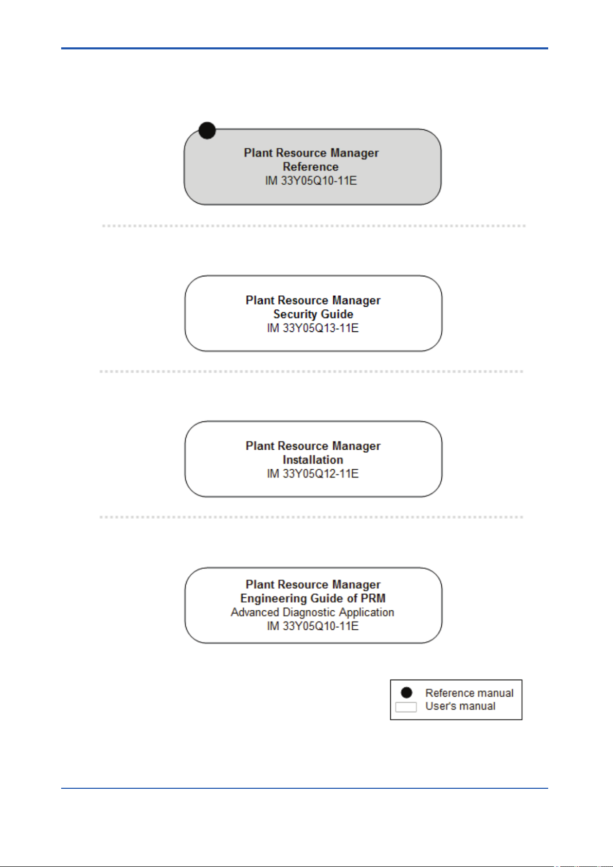
Plant Resource Manager Document Map
Reference
n
Security Guide
n
ii
Installation
n
PRM Advanced Diagnostic Application
n
IM 33Y05Q10-11E 7th Edition : Feb.08,2012-00
Page 4

Safety precautions
Safety, protection, and modification of the product
n
• To protect the system controlled by the product and the product itself and ensure safe operation, observe the safety precautions described in this user's manual . Yokogawa Electric Corporation (hereinafter referred to as YOKOGAWA) assumes no liability for safety if
users fail to observe the safety precautions and instructions when operating the product.
• If this product is used in a manner not specified in this user's manual, the protection provided by this product may be impaired.
• If any protection or safety circuit is required for the system controlled by the product or for
the product itself, install it externally.
• Use only spare parts that are approved by YOKOGAWA when replacing parts or consumables of the product.
• Do not use the product and accessories of the product such as power cords on devices
that are not approved by YOKOGAWA. Do not use the product and its accessories for
other purposes.
• Modification of the product is strictly prohibited.
• The following symbols are used in the product and user's manual to indicate the accompanying safety precautions:
iii
Indicates that caution is required for operation. This symbol is placed on the product to
refer the user to the user's manual to protect the operator and the equipment. In the
user's manual, you will find precautions to avoid physical injury and/or death, which
may be caused by accidents, such as electrical shocks resulting from operation mistakes.
Identifies a protective grounding terminal. Before using the product, ground the terminal.
Identifies a functional grounding terminal.
Indicates an AC supply.
Indicates a DC supply.
Indicates that the power supply switch is ON.
Indicates that the power supply switch is OFF.
Notes on handling user's manuals
n
• Hand over the user's manuals to your end users so that they can keep the user's manuals
on hand for reference.
• Read and understand the information in the user's manual thoroughly before using the
product.
• For the avoidance of any doubt, the purpose of these user's manuals is not to warrant
that the product is suitable for any particular purpose but to describe the functional details
of the product.
• YOKOGAWA reserves the right to make improvements in the user's manuals and product
at any time, without notice or obligation.
• Every effort has been made in the preparation of this manual to ensure the accuracy of its
contents. However, should you have any questions or find any errors, contact our sales
IM 33Y05Q10-11E 7th Edition : Feb.08,2012-00
Page 5

representative or your local distributor. Manuals with incorrectly ordered pages or missing
pages will be replaced.
Warning and disclaimer
n
• The product is provided on an "as is" basis.
• YOKOGAWA shall have neither liability nor responsibility to any person or entity with respect to any direct or indirect loss or damage arising from using the product or any defect
of the product that YOKOGAWA can not predict in advance.
Notes on software
n
• YOKOGAWA makes no warranties, either expressed or implied, with respect to the software’s merchantability or suitability for any particular purpose, except as strictly provided
in the terms of warranty.
• The software may be used only on the specified computer. If you need to use the software on another computer, you must purchase another software.
• It is strictly prohibited and an infringement of YOKOGAWA's Intellectual Property rights to
reproduce the software except for the purpose of backup.
• Store all the original media that comes with the product in a safe place.
iv
• It is strictly prohibited and an infringement of YOKOGAWA's Intellectual Property rights to
reverse engineer, reverse compile, reverse assemble, or reduce the software to humanreadable form.
• No part of the software may be transferred, converted, or sublet for use by any third-party,
without prior written consent from YOKOGAWA, failing which any warranty statements
provided for the product and/or software shall be rendered void.
IM 33Y05Q10-11E 7th Edition : Feb.08,2012-00
Page 6

Documentation conventions
Symbol marks
n
The following symbols identify various sections of text in this user's manual.
Identifies instructions that must be observed to avoid physical
injury, electric shock, or death.
Identifies instructions that must be observed to prevent damages to the software or hardware, or defects to the system.
Identifies important information required to understand operations or functions.
Identifies additional information.
Identifies referenced content.
You can view the referenced content by clicking the green text.
v
Typographical conventions
n
The following typographical conventions are used throughout the user's manuals.
Commonly used conventions throughout user's manuals
l
• Character string to be entered
The characters that must be entered are shown in monospace font as follows:
Example:
FIC100.SV=50.0
"∆" mark indicates a space between character strings that must be entered.
Example:
AL∆PIC010∆-SC
• Character string enclosed by brackets ({ })
Indicates an option that can be omitted.
Example:
.PR∆TAG{∆.sheet name}
This action does not apply to the black text.
Conventions used to show key or button operations
l
Characters enclosed by brackets ([ ])
In descriptions of key or button operations, words enclosed in brackets indicate either a key
on the HIS (Human Interface Station) keyboard, a key on the operation keyboard, a button
name in a window, or an item on a list box displayed in a window.
Example:
To alter the function, press the [ESC] key.
IM 33Y05Q10-11E 7th Edition : Feb.08,2012-00
Page 7

Conventions used in command syntax or program statements
l
The following conventions are used within a command syntax or program statement format.
• Characters enclosed by angle-brackets
Indicate character strings that user can specify freely according to certain guidelines.
Example:
#define <Identifier><Character string>
"..." mark
Indicates that the previous command or argument may be repeated
Example:
Imax (arg1, arg2, ...)
• Characters enclosed by brackets ([ ])
Indicate those character strings that can be omitted.
Example:
sysalarm format_string[output_value ...]
• Characters enclosed by separators (| |)
vi
Indicate those character strings that can be selected from more than one option.
Example:
opeguide <format_character_string> [, <output_value> ...]
Drawing conventions
n
Some drawings may be partially emphasized, simplified, or omitted for the convenience of description.
In the user's manual, the parts in some drawings may be placed in different positions or have
different font settings. Note that some of the images in user's manuals are display examples.
OG,<element number>
IM 33Y05Q10-11E 7th Edition : Feb.08,2012-00
Page 8

Copyright and trademark notices
All rights reserved
n
The copyright of the programs and online manuals contained in the software media shall remain with YOKOGAWA.
You are allowed to print the required pages of the online manuals for the purposes of using
and/or operating the product. However, you are not allowed to print or reproduce the entire
document. You can purchase the printed manual from YOKOGAWA.
Except as stated above, no part of the online manual may be reproduced, either in electronic
or written form, registered, recorded, transferred, sold, or distributed (in any manner including
without limitation, in the forms of paper documents, electronic media, films, or transmission
via the network). Any in-action and/or silence by YOKOGAWA with regard to any breach of
the above shall not be taken as any waiver of its rights whatsoever and YOKOGAWA reserves all its rights until expressly waived by written notification and no other occasions.
Trademark acknowledgments
n
• PRM is a registered trademark of Yokogawa Electric Corporation in the United States and
Japan.
vii
• CENTUM, Vnet/IP, and ProSafe are registered trademarks of YOKOGAWA.
• STARDOM is a trademark.
• Microsoft, Windows, Windows Vista, Visual Basic, Visual C++, and Visual Studio are either registered trademarks or trademarks of Microsoft Corporation in the United States
and/or other countries.
• Pentium is a registered trademark of Intel Corporation.
• Adobe and Acrobat are either registered trademarks or trademarks of Adobe Systems Incorporated in the United States and/or other countries.
• Oracle is a registered trademark of ORACLE Corporation.
• Maximo is a registered trademark of IBM.
• System 1, Bently Nevada, and Trendmaster are trademarks of General Electric Company.
• Ethernet is a registered trademark of XEROX Corporation.
• Java is a registered trademark of Sun Microsystems,Inc.
•
• HART is a registered trademark of HART Communication Foundation.
• All other company and product names mentioned in this manual are trademarks or registered trademarks of their respective companies.
• TM or ® mark are not used to indicate trademarks or registered trademarks in this manual.
in fieldbus is a registered trademark of Fieldbus Foundation.
• We do not use logos and logo marks in this manual.
IM 33Y05Q10-11E 7th Edition : Feb.08,2012-00
Page 9

TocA-1
Plant Resource Manager Reference
IM 33Y05Q10-11E 7th Edition
CONTENTS
PART-A About PRM.......................................................A-1
A1. The Plant Resource Manager............................................................A1-1
A2. PRM packages....................................................................................A2-1
A3. How PRM works.................................................................................A3-1
A3.1 Device connection methods.....................................................................A3-3
A4. Features..............................................................................................A4-1
IM 33Y05Q10-11E 7th Edition : Feb.08,2012-00
Page 10

TocB-1
Plant Resource Manager Reference
IM 33Y05Q10-11E 7th Edition
CONTENTS
PART-B Configuring PRM.............................................B-1
B1. Tasks after new installation..............................................................B1-1
B2. PRM Server.........................................................................................B2-1
B2.1 Server sets..................................................................................................B2-3
B3. Field Communications Server..........................................................B3-1
B3.1 Device path.................................................................................................B3-2
B3.1.1 Configuring device paths.............................................................B3-8
B3.1.2 Devices connected to CENTUM................................................B3-16
B3.1.3 Devices connected to STARDOM..............................................B3-22
B3.1.4 Devices connected to ProSafe-RS............................................B3-25
B3.1.5 Devices connected locally..........................................................B3-26
B3.2 FDT projects.............................................................................................B3-28
B3.2.1 Managing FDT projects..............................................................B3-32
B3.2.2 Configuring FDT projects...........................................................B3-36
B3.3 DD files......................................................................................................B3-51
B3.3.1 Installing DD files of other manufacturers..................................B3-53
B3.3.2 DD Copy Tool.............................................................................B3-54
B4. PRM Client..........................................................................................B4-1
B4.1 PRM Client connection settings...............................................................B4-2
B4.2 Customizing the appearance....................................................................B4-5
B4.3 Label customization...................................................................................B4-6
B4.4 DTM Setup..................................................................................................B4-7
B4.5 Copying DD files......................................................................................B4-10
B4.6 Fast Device Patrol settings for HART devices......................................B4-11
B5. Managing accounts and device security.........................................B5-1
B5.1 Group and user accounts..........................................................................B5-2
B5.1.1 PRM groups.................................................................................B5-3
B5.1.2 PRM user accounts......................................................................B5-8
B5.2 Managing device security.......................................................................B5-15
B5.2.1 Configuring device security........................................................B5-17
B5.2.2 Device security configuration examples.....................................B5-19
B6. Managing master data.......................................................................B6-1
IM 33Y05Q10-11E 7th Edition : Feb.08,2012-00
Page 11

TocB-2
B6.1 Importing and exporting master data.......................................................B6-3
B6.2 Device icons...............................................................................................B6-5
B6.2.1 Device icon assignment...............................................................B6-9
IM 33Y05Q10-11E 7th Edition : Feb.08,2012-00
Page 12

TocC-1
Plant Resource Manager Reference
IM 33Y05Q10-11E 7th Edition
CONTENTS
PART-C Working with the PRM Client..........................C-1
C1. Getting started with the PRM Client.................................................C1-1
C1.1 Accessing the PRM Client.........................................................................C1-2
C1.2 Using the PRM window..............................................................................C1-4
C1.2.1 Using the Device Navigator.........................................................C1-6
C1.2.2 Using the function pane...............................................................C1-8
C1.3 Changing server sets in the PRM Client................................................C1-13
C1.4 Using context search...............................................................................C1-14
C1.5 Viewing online manuals..........................................................................C1-16
C2. Working with the Device Navigator..................................................C2-1
C2.1 Plant view....................................................................................................C2-2
C2.1.1 Plant view structure.....................................................................C2-3
C2.1.2 Plant view operations...................................................................C2-5
C2.2 Network view..............................................................................................C2-8
C2.2.1 Network view structure................................................................C2-9
C2.2.2 Network view operations............................................................C2-14
C2.3 Class view.................................................................................................C2-19
C2.3.1 Class view structure...................................................................C2-20
C2.3.2 Class view operations................................................................C2-23
C2.4 Custom view.............................................................................................C2-25
C2.4.1 Custom view structure...............................................................C2-26
C2.4.2 Custom view operations............................................................C2-27
C3. Printing reports using the Self Document feature..........................C3-1
C3.1 Printing reports..........................................................................................C3-2
C3.2 Report structures.......................................................................................C3-9
C4. Searching using the Facility & Inspection Browser.......................C4-1
C4.1 Searching for information.........................................................................C4-4
C4.2 Searching for parameter data...................................................................C4-6
C4.3 Working with search results.....................................................................C4-9
IM 33Y05Q10-11E 7th Edition : Feb.08,2012-00
Page 13

TocD-1
Plant Resource Manager Reference
IM 33Y05Q10-11E 7th Edition
CONTENTS
PART-D Managing devices............................................D-1
D1. Registering devices...........................................................................D1-1
D1.1 Device registration methods.....................................................................D1-2
D1.2 Device registration.....................................................................................D1-3
D1.2.1 Plug & Play..................................................................................D1-4
D1.2.2 Host file set import.......................................................................D1-9
D1.2.3 Manual registration....................................................................D1-12
D1.2.4 Maintenance information import................................................D1-15
D1.2.5 FieldMate synchronization.........................................................D1-16
D1.2.6 Detecting HART devices connected to a multiplexer.................D1-17
D1.3 Replacing devices....................................................................................D1-19
D1.3.1 Updating device information in PRM after replacing devices..............
...................................................................................................D1-22
D1.3.2 Device information inheritance function.....................................D1-23
D1.4 Updating device details...........................................................................D1-25
D1.5 Changing the network location of devices............................................D1-27
D1.6 Deleting devices.......................................................................................D1-33
D2. Viewing and modifying device details.............................................D2-1
D2.1 Device tag display extension....................................................................D2-2
D2.1.1 Device tag display extension for HART devices..........................D2-3
D2.1.2 Device tag display extension for devices in STARDOM upstream
projects........................................................................................D2-4
D2.1.3 Configuring the device tag display extension in PRM..................D2-5
D2.1.4 Device tag display extension specifications.................................D2-7
D2.2 Viewing the device list in the Device List window..................................D2-9
D2.3 Viewing device details in the Device Details window...........................D2-11
D2.4 Modifying or updating devices...............................................................D2-17
D2.5 Exporting and importing the device list.................................................D2-18
D2.6 Customizing user-definable fields..........................................................D2-22
D3. Validating HART device ranges........................................................D3-1
D3.1 Validating HART device ranges................................................................D3-3
D3.1.1 Acquiring CENTUM HART range information..............................D3-4
D3.1.2 Acquiring PRM HART range information.....................................D3-6
IM 33Y05Q10-11E 7th Edition : Feb.08,2012-00
Page 14

TocD-2
D3.1.3 Comparing HART range information............................................D3-7
D3.2 HART device range validation procedure..............................................D3-13
D3.2.1 Validation operation flow of HART device ranges......................D3-14
D3.2.2 Acquiring CENTUM HART range information............................D3-16
D3.2.3 Acquiring PRM range information..............................................D3-17
D3.2.4 Acquiring HART range comparison result..................................D3-18
D3.3 Handling errors........................................................................................D3-19
D4. Using device templates.....................................................................D4-1
D4.1 Device classes............................................................................................D4-2
D4.2 Registering devices during plant commissioning..................................D4-3
D4.2.1 Using device templates................................................................D4-4
D4.2.2 Without using device templates...................................................D4-6
D4.3 Device template contents..........................................................................D4-8
D4.4 When to apply device templates...............................................................D4-9
D4.5 Working with device templates...............................................................D4-14
D5. Managing parts..................................................................................D5-1
D5.1 Parts code...................................................................................................D5-2
D5.2 Parts list......................................................................................................D5-5
D6. Managing document links.................................................................D6-1
D6.1 Registering documents in PRM................................................................D6-2
D6.2 Using document links................................................................................D6-5
D7. Importing and exporting maintenance information........................D7-1
IM 33Y05Q10-11E 7th Edition : Feb.08,2012-00
Page 15

TocE-1
Plant Resource Manager Reference
IM 33Y05Q10-11E 7th Edition
CONTENTS
PART-E Monitoring and diagnosing devices..............E-1
E1. Handling maintenance alarms..........................................................E1-1
E1.1 Contents of maintenance alarms..............................................................E1-5
E1.2 Configuring maintenance alarms.............................................................E1-8
E1.2.1 Configuring initial system settings..............................................E1-10
E1.2.2 Device settings...........................................................................E1-15
E1.2.3 Alarm management rules...........................................................E1-17
E1.2.4 Notification rules........................................................................E1-28
E1.3 Maintenance alarm messages.................................................................E1-36
E2. Using the Diagnosis window............................................................E2-1
E2.1 Device status integration...........................................................................E2-5
E2.2 Configuring Status Override...................................................................E2-12
E3. Viewing the status of a device..........................................................E3-1
E3.1 Device status icon......................................................................................E3-2
E3.1.1 Status colors................................................................................E3-3
E3.1.2 Status display...............................................................................E3-4
E3.1.3 Managing device status...............................................................E3-6
E3.2 Unacknowledged alarm icon.....................................................................E3-8
E3.3 Usage states.............................................................................................E3-10
E4. Diagnosing devices using DeviceViewer.........................................E4-1
E4.1 DeviceViewer window................................................................................E4-3
E4.1.1 Periodic mode..............................................................................E4-4
E4.1.2 Diagnostic Information tab...........................................................E4-5
E4.1.3 Trend Information tab...................................................................E4-8
E5. Working with maintenance marks....................................................E5-1
E5.1 Managing MTMK definitions......................................................................E5-6
E5.2 Configuring synchronization with CENTUM operation marks.............E5-11
E5.2.1 Configuring MTMK settings in the PRM Setup Tool...................E5-15
E5.2.2 Mapping CENTUM function blocks to PRM devices..................E5-17
E5.2.3 Configuring device-level synchronization settings.....................E5-18
E5.3 Configuring MTMK-related notifications................................................E5-19
E5.4 Setting and removing MTMKs in the PRM Client..................................E5-20
IM 33Y05Q10-11E 7th Edition : Feb.08,2012-00
Page 16

TocE-2
E5.5 Triggering synchronization in the Device Navigator............................E5-24
E5.6 Examples of synchronization with CENTUM.........................................E5-25
E5.6.1 Example: Unidirectional synchronization initiated from CENTUM.......
...................................................................................................E5-26
E5.6.2 Example: Bidirectional synchronization initiated from both PRM and
CENTUM....................................................................................E5-30
E6. Inspecting devices.............................................................................E6-1
E6.1 Managing service codes............................................................................E6-3
E6.2 Managing inspection schedules...............................................................E6-6
E6.3 Managing inspection memos..................................................................E6-11
E6.4 Reference codes.......................................................................................E6-21
E7. Working with history records...........................................................E7-1
E7.1 History window...........................................................................................E7-5
IM 33Y05Q10-11E 7th Edition : Feb.08,2012-00
Page 17

TocF-1
Plant Resource Manager Reference
IM 33Y05Q10-11E 7th Edition
CONTENTS
PART-F Configuring device parameters......................F-1
F1. Adjusting device parameters............................................................F1-1
F1.1 Adjusting parameters.................................................................................F1-5
F1.2 Using Parameter Manager.......................................................................F1-16
F1.3 Using DTM Works.....................................................................................F1-27
F1.4 Using DD Menu for FF-H1 devices..........................................................F1-36
F1.5 Connecting to FieldMate..........................................................................F1-39
F2. Managing calibration data.................................................................F2-1
F2.1 Workflow for managing calibration data..................................................F2-5
F2.1.1 Using a conventional device........................................................F2-6
F2.1.2 Using a Documenting Calibrator..................................................F2-9
F2.2 Working with calibration data.................................................................F2-13
F2.3 Viewing and modifying calibration data details....................................F2-17
F2.4 Managing calibration groups..................................................................F2-28
F2.5 Downloading and uploading calibration data........................................F2-31
F2.6 Approving calibration data......................................................................F2-34
F2.7 Printing documents related to calibration.............................................F2-37
F2.8 Exporting and importing of calibration data..........................................F2-39
F3. Using PLUG-IN applications..............................................................F3-1
F3.1 Working with PLUG-IN applications.........................................................F3-2
IM 33Y05Q10-11E 7th Edition : Feb.08,2012-00
Page 18

TocG-1
Plant Resource Manager Reference
IM 33Y05Q10-11E 7th Edition
CONTENTS
PART-G Maintaining PRM.............................................G-1
G1. Backing up and restoring PRM data................................................G1-1
G1.1 Using the Fast Backup tool.......................................................................G1-2
G1.2 Using the PRM System Backup Script.....................................................G1-6
G2. Maintaining PRM databases.............................................................G2-1
G2.1 Archiving, retrieving, and deleting data..................................................G2-5
G2.1.1 Procedures..................................................................................G2-7
G2.2 Cleaning up the PRM database..............................................................G2-13
G2.3 Cleaning up the Historian database.......................................................G2-15
IM 33Y05Q10-11E 7th Edition : Feb.08,2012-00
Page 19

TocH-1
Plant Resource Manager Reference
IM 33Y05Q10-11E 7th Edition
CONTENTS
PART-H Performing an advanced diagnosis...............H-1
H1. Advanced diagnosis..........................................................................H1-1
H1.1 Software packages.....................................................................................H1-2
H1.2 How it works...............................................................................................H1-4
H1.3 Data acquisition.........................................................................................H1-9
H1.4 Device Diagnosis Data Historian............................................................H1-12
H1.5 Replacing, renaming, and deleting devices..........................................H1-14
H2. Preparing for an advanced diagnosis..............................................H2-1
H2.1 Deciding on the system configuration.....................................................H2-2
H2.2 Configuration settings...............................................................................H2-4
H2.3 Acquiring and storing device diagnostic parameters............................H2-6
H3. Starting the advanced diagnosis using the Diagnosis Navigator.........
.............................................................................................................H3-1
H3.1 Opening and closing Diagnosis Navigator..............................................H3-3
H3.2 Managing PAAs..........................................................................................H3-6
H3.3 Managing diagnosis modules...................................................................H3-9
H3.4 Monitoring diagnosis modules...............................................................H3-17
H3.5 Importing and exporting diagnosis module information.....................H3-20
H4. Monitoring an advanced diagnosis..................................................H4-1
H5. Displaying graphical results using the General-purpose Diagnostic
Tool......................................................................................................H5-1
H5.1 Using GDT...................................................................................................H5-3
H5.2 Trend graphs............................................................................................H5-10
H5.3 Correlation graphs...................................................................................H5-13
H5.4 Exporting data..........................................................................................H5-16
IM 33Y05Q10-11E 7th Edition : Feb.08,2012-00
Page 20

TocI-1
Plant Resource Manager Reference
IM 33Y05Q10-11E 7th Edition
CONTENTS
PART-I Working with the PST Scheduler.....................I-1
I1. About the PST Scheduler...................................................................I1-1
I2. Getting started with the PST Scheduler Client.................................I2-1
I3. Configuring the PST Scheduler.........................................................I3-1
I3.1 Managing users...........................................................................................I3-2
I3.1.1 Managing user roles......................................................................I3-4
I3.1.2 Managing user teams....................................................................I3-7
I3.1.3 Managing user accounts...............................................................I3-9
I3.2 Managing devices and groups.................................................................I3-12
I3.2.1 Importing device information.......................................................I3-14
I3.2.2 Managing PST groups.................................................................I3-19
I3.2.3 Managing hierarchy.....................................................................I3-26
I3.3 Configuring alarm and notification rules................................................I3-28
I3.4 Customizing the PST Scheduler Client interface...................................I3-30
I4. Operating the PST Scheduler.............................................................I4-1
I4.1 Scheduling a PST........................................................................................I4-2
I4.2 Manually performing PSTs........................................................................I4-12
I4.3 Registering test results and assigning PST schedules.........................I4-15
I5. Monitoring PSTs..................................................................................I5-1
I5.1 Viewing PST schedules and status............................................................I5-2
I5.2 Viewing group and device details............................................................I5-11
I6. Backing up and restoring PST Scheduler data................................I6-1
I6.1 Backing up PST Scheduler data.................................................................I6-2
I6.2 Restoring PST Scheduler data...................................................................I6-4
IM 33Y05Q10-11E 7th Edition : Feb.08,2012-00
Page 21

TocJ-1
Plant Resource Manager Reference
IM 33Y05Q10-11E 7th Edition
CONTENTS
PART-J Connecting PRM to a CMMS...........................J-1
J1. About CMMS.......................................................................................J1-1
J2. Connecting PRM to Maximo..............................................................J2-1
J2.1 Configuring PRM and Maximo...................................................................J2-2
J2.1.1 Configuring PRM..........................................................................J2-3
J2.1.2 Configuring Maximo......................................................................J2-6
J2.1.3 Synchronizing hierarchical structure and device information.....J2-14
J2.1.4 Managing work orders................................................................J2-20
J2.1.5 Device management after connecting to Maximo......................J2-22
IM 33Y05Q10-11E 7th Edition : Feb.08,2012-00
Page 22

TocK-1
Plant Resource Manager Reference
IM 33Y05Q10-11E 7th Edition
CONTENTS
PART-K Integrating a third-party system.....................K-1
K1. PRM and System 1 integration.........................................................K1-1
K1.1 How it works...............................................................................................K1-6
K1.2 Requirements.............................................................................................K1-7
K1.3 Engineering procedure to connect System 1........................................K1-10
IM 33Y05Q10-11E 7th Edition : Feb.08,2012-00
Page 23

TocApp.-1
Plant Resource Manager Reference
IM 33Y05Q10-11E 7th Edition
CONTENTS
Appendix
Appendix 1. Help codes.......................................................................App.1-1
Appendix 2. Error codes......................................................................App.2-1
Appendix 3. History messages stored in the PRM database...........App.3-1
Appendix 4. Glossary...........................................................................App.4-1
IM 33Y05Q10-11E 7th Edition : Feb.08,2012-00
Page 24

A. About PRM
This part provides general information about PRM.
Overview
n
This part consists of the following sections:
• The Plant Resource Manager
Briefly describes PRM.
• PRM packages
Identifies the basic and optional packages.
• How PRM works
Describes how PRM works and identifies the supported device communication types and
connection methods.
• Features
Describes the key PRM features and explains their availability.
<A. About PRM> A-1
IM 33Y05Q10-11E 7th Edition : Feb.08,2012-00
Page 25

<A1. The Plant Resource Manager>
A1. The Plant Resource Manager
Plant Resource Manager (PRM), a key component of the YOKOGAWA VigilantPlant Asset
Excellence initiative, is a centralized asset management system that helps to reduce plant
downtime and maintenance costs.
PRM enables you to:
• Manage device information within the plant
• Monitor device status and alarms
• Manage device inspection activities
• Configure device parameters and settings
• Manage calibration information
• Perform advanced diagnostic analysis
PRM can be configured to manage assets used for a variety of systems within a plant, including:
• CENTUM
• ProSafe-RS
A1-1
• STARDOM
PRM can also connect to the following systems and applications from third-party vendors to
expand its asset maintenance management coverage:
• IBM Maximo Asset Management
• GE Energy's System 1
• PLUG-IN applications from device vendors
IM 33Y05Q10-11E 7th Edition : Feb.08,2012-00
Page 26

A2. PRM packages
PRM includes basic and optional packages. Each package requires a license.
Basic packages
n
A PRM installation requires the following basic packages:
PRM Server
l
The PRM Server collects device information and saves it to the database. This information includes messages, device parameters, inspection data, and other related information used in
device management.
PRM Client
l
PRM Client is a graphical user interface application used to view device information, monitor
device status, and perform various operations related to device management.
Field Communications Server
l
The Field Communications Server acts as the gateway between PRM and apparatuses to
which devices are connected. The following are examples of apparatuses:
<A2. PRM packages>
A2-1
• CENTUM Field Control Station (FCS)
• ProSafe-RS Safety Control Station (SCS)
• STARDOM Field Control Node (FCN)
• STARDOM Field Control Junction (FCJ)
• HART multiplexer
PRM can connect to multiple apparatuses simultaneously. To establish the connection, the
apparatus and the computer on which the Field Communications Server is installed must be
on the same network. Multiplexers, on the other hand, must be connected directly to the COM
port of the Field Communications Server computer.
Optional packages
n
The following packages provide additional functionality to PRM:
PRM Advanced Diagnostic Server
l
PRM Advanced Diagnostic Server enables you to perform advanced device diagnosis using
algorithmic logic called PRM Advanced Diagnostic Applications (PAA). It comprises two major
components, the Advanced Diagnosis and the Device Diagnosis Data Historian.
PRM Advanced Diagnostic Application Development Kit
l
PRM Advanced Diagnostic Application Development Kit is used to develop or customize PRM
Advanced Diagnostic Applications (PAA).
Documenting Calibrator Interface
l
Documenting Calibrator Interface is used as an interface to documenting calibrators such as
FLUKE.
Interface for CMMS
l
The Interface for CMMS is used to connect PRM to a Computerized Maintenance Management System (CMMS).
IM 33Y05Q10-11E 7th Edition : Feb.08,2012-00
Page 27

<A2. PRM packages> A2-2
Interface for GE Energy's System 1
l
Interface for GE Energy's System 1 is used to connect PRM to GE Energy's System 1 and
monitor the status of rotating machinery connected to System 1.
PST Scheduler
l
PST Scheduler is used to schedule, conduct, and monitor partial stroke tests for emergency
shutdown (ESD) valves.
IM 33Y05Q10-11E 7th Edition : Feb.08,2012-00
Page 28

A3. How PRM works
PRM provides a convenient way of obtaining the health condition of instrumentation equipment throughout the plant from a single location. PRM does this by periodically communicating with devices and displaying the device status represented by color-coded icons in the
PRM Client. You can also initiate a request to obtain the device status in real time.
To communicate with devices, the Field Communications Server of PRM needs to be connected to the apparatuses to which field devices are connected. The following are examples of
apparatuses:
• CENTUM Field Control Station (FCS)
• ProSafe-RS Safety Control Station (SCS)
• STARDOM Field Control Node (FCN)
• STARDOM Field Control Junction (FCJ)
• HART multiplexer
PRM can connect to multiple apparatuses simultaneously.
PRM works most effectively with smart devices such as flow meters, control valves, rotating
machinery, among other devices commonly found in plants. These are devices that have the
capability to communicate with PRM digitally. You can use information from smart devices to
perform device diagnosis. You can also utilize advanced PRM capabilities for diagnostic analysis through the use of logical algorithms called PRM Advanced Diagnostic Application (PAA).
However, you can also register static devices or other plant assets considered as important
components in your plant processes. If there are alarms or abnormalities, you can use several
tools in PRM to configure device parameters and settings remotely without going to the actual
location of the device.
<A3. How PRM works>
A3-1
PRM can be customized to match the existing operations and procedures you conduct in your
plant. For example, you can create rule sets to define how alarms and messages will be processed. This gives you the capability to add necessary information about the issue, cause, or
recommended action in the message so that the intended recipient understands clearly how
to handle the message. You can also define notification rules to determine if PRM should
block or relay the information to an engineer or another computer station in the network.
IM 33Y05Q10-11E 7th Edition : Feb.08,2012-00
Page 29
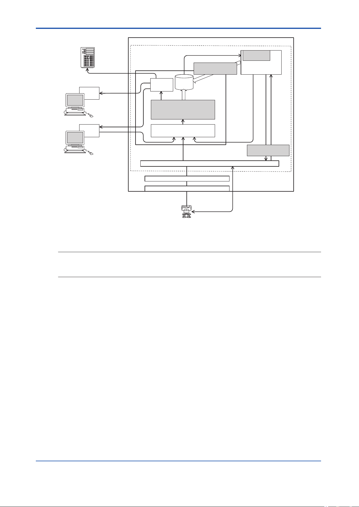
PRM
database
OPC
server
Basic PRM system
Field Communications Server
Control bus, Field network
Field devices
Device
parameter
PRM Server
Acquiring device parameters
(device diagnosis information)
· Device management
· Audit trail
Online device
parameter adjustment
Saving maintenance
alarm message
Operator guide
notification
Acquiring
alarm notification
Manual
alarm input
SMTP Server
(E-mail Server)
HIS or other systems
(System 1, OPC interface)
Alarm
notification
E-mail
notification
- Alarm management
- Basic diagnosis
CAMS
for HIS
HIS
Hardware (Control bus, Communication port)
Communication driver
PRM Client
Device status
display
Message and data
acquisition
Message
notification
<A3. How PRM works>
A3-2
SEE
ALSO
GUID-A5C69D43-5993-4602-987A-53753DD51CD0-default-pdf.pdf
Figure A3-1 PRM in a plant
For more information about PRM installation and configuration procedures, refer to:
Plant Resource Manager Installation (IM 33Y05Q12-11E)
IM 33Y05Q10-11E 7th Edition : Feb.08,2012-00
Page 30
PRM
Server
PRM
Client
Field
Communications
Server
PROFIBUS
DP/PA
coupler
Ethernet/
PROFIBUS
converter
V net
Ethernet
multiplexer
Field
Wireless
integrated
gateway
FF-H1/HSE
linking device
PROFIBUS
PROFIBUS PA
device
PROFIBUS DP
device
HART
device
FF-H1
device
HART
device
FF-H1
device
Device path configuration
FDT project configuration
ISA100
wireless device
HART
device
PROFIBUS
I/O module
Other FDT-
compliant
devices
ALE111
Ethernet
Layer-3
switch
RS-485/Ethernet
converter
FF-H1
I/O module
HART
I/O module
Other
FDT-compliant
communication
devices
PROFIBUS/
HART
converter
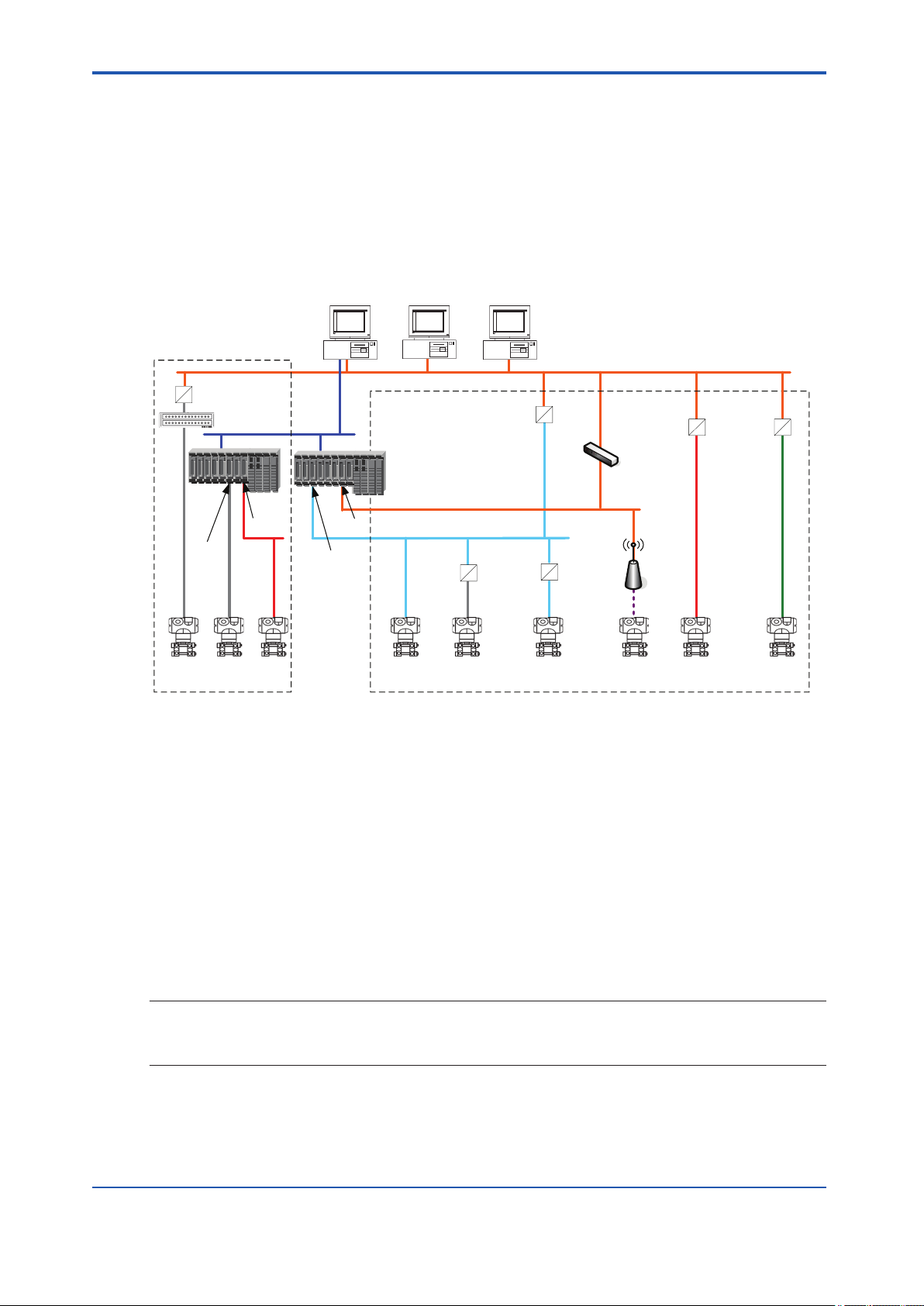
<A3.1 Device connection methods>
A3.1 Device connection methods
PRM can communicate with devices that use different communication types and connection
methods. To connect to a particular device, you must either configure a device path or a Field
Device Tool (FDT) project. The following diagram shows the connection methods that PRM
supports and classifies them into these categories:
• Device path configuration
• FDT project configuration
A3-3
GUID-75FFEA0F-3C37-4C11-B4DA-D301E0222992-default-pdf.pdf
Figure A3.1-1 Device connection methods
Device path configuration
n
A device path is a communication path to the location on the physical network to which a device is connected. You must configure device paths to enable PRM to communicate with the
following devices:
• FF-H1 and HART devices connected to an I/O module on CENTUM or STARDOM
• HART devices connected to an I/O module on ProSafe-RS
• FF-H1 devices connected to the Field Communications Server through an NI-FBUS card
• HART devices connected to the Field Communications Server through a multiplexer or
modem
SEE
For more information about configuring device paths, refer to:
ALSO
n
B3.1, “Device path” on page B3-2
FDT project configuration
A Field Device Tool (FDT) project defines a network topology comprising of communication,
gateway, and device DTMs, and stores the configuration settings of all the DTMs in the topol-
IM 33Y05Q10-11E 7th Edition : Feb.08,2012-00
Page 31

<A3.1 Device connection methods> A3-4
ogy. You must configure FDT projects to enable PRM to communicate with the following devices:
• FF-H1 devices connected to an FF-H1/HSE linking device
• PROFIBUS PA and DP devices connected to an Ethernet/PROFIBUS converter
• HART devices connected to a PROFIBUS network through a PROFIBUS/HART converter
• ISA100 devices connected to a ISA100 wireless gateway
• FDT-compliant devices connected to other FDT-compliant communication devices
When PRM communicates with a device defined on an FDT project, PRM Client contacts the
Field Communications Server. The Field Communications Server then runs the required communication and gateway DTMs.
SEE
For more information about PROFIBUS DP and PA, refer to:
ALSO
“n PROFIBUS” on page App.4-6
For more information about configuring FDT projects, refer to:
B3.2, “FDT projects” on page B3-28
For more information about the definitions of FDT and DTM, refer to:
Appendix 4., “Glossary” on page App.4-1
IM 33Y05Q10-11E 7th Edition : Feb.08,2012-00
Page 32

<A4. Features>
A4. Features
This section describes the key PRM features. It also explains feature availability for each
combination of device communication type and connection method.
Store device maintenance information in a central location
n
PRM acts as the central database for device maintenance information. This information can
include details about device parts, links to device documents, device description files, details
about device inspection activities, device parameter history, and device messages. You can
also use PRM to manage the information acquired from device calibration tools and applications by downloading or synchronization.
Record all activities, events, and messages
n
PRM tracks and records all activities, events, messages, and system transactions as history
information in the PRM database.
SEE
For more information about history information, refer to:
ALSO
E7.1, “History window” on page E7-5
A4-1
Support multiple server architecture
n
PRM supports a multiserver configuration. Multiple servers are necessary to distribute the
load and stabilize the computing performance in a plant that has many devices. A single PRM
Client can connect to different servers, one at a time, to monitor the status of devices registered in each server.
Monitor device status and alarm messages
n
From PRM, you can monitor real-time device status and alarm messages for devices being
used in the plant. Performing this activity from a central location gives you the capability to
react faster and maintain the reliability of the plant.
SEE
For more information about monitoring device status, refer to:
ALSO
E3., “Viewing the status of a device” on page E3-1
Display devices organized in different views
n
PRM can display devices in different views. Each view is organized in a different structure.
The structure can be based on the plant hierarchy, network, classification, or a customized
structure.
SEE
For more information about the different views, refer to:
ALSO
C2., “Working with the Device Navigator” on page C2-1
By plant hierarchy
l
You can view devices according to the plant hierarchy prescribed by the ISA 88.01 standard.
The plant hierarchy provides a clear view about your plant setup.
IM 33Y05Q10-11E 7th Edition : Feb.08,2012-00
Page 33

<A4. Features>
By network
l
You can view devices based on the network they belong. In this view, you will see how a device is physically connected to the network. You can also filter the devices that appear in the
view based on their communication type.
By class
l
You can view devices based on classes such as communication type, vendor, model, and release version.
Custom
l
You can create a customized structure for devices in the Custom view. This view enables you
to organize devices based on the unique requirements in your plant.
Manage devices used within different kinds of plant control systems
n
PRM can be used to manage and receive messages from devices being used in different
kinds of plant control systems.
SEE
For more information about the requirements for connecting with different plant control systems, refer to:
ALSO
Plant Resource Manager Installation (IM 33Y05Q12-11E)
A4-2
CENTUM
l
PRM can manage devices connected to CENTUM, an integrated production control system.
To use PRM to determine the device status and perform device parameter adjustment for devices connected to CENTUM, the computer on which the PRM Field Communications Server
is installed needs to be in the same network as the CENTUM Field Control Station (FCS).
TIP
A single PRM Server cannot be connected to multiple CENTUM systems. To connect to multiple CENTUM
systems, multiple PRM server sets are required.
ProSafe-RS
l
PRM can manage devices connected to ProSafe-RS, a safety-instrumented system. To establish the connection, the Field Communications Server of PRM needs to be in the same
network as the Safety Control Station (SCS) of ProSafe-RS.
As part of plant safety measures, you can use PRM, ProSafe-RS, and PLUG-IN ValVue ESD
to conduct a Partial Stroke Test (PST). ProSafe-RS shuts down the plant process when a failure occurs. PST is a proof test conducted to periodically test valves to ensure that they will
respond in case a shutdown event occurs.
TIP
• PRM can communicate with HART devices in a ProSafe-RS system, making it unnecessary to install additional wiring and multiplexers.
• When PRM is connected to ProSafe-RS and CENTUM systems, alarm messages of these systems are
acquired through the CENTUM OPC Server.
IM 33Y05Q10-11E 7th Edition : Feb.08,2012-00
Page 34

Control Bus
FCS
Device
Viewer
PRM
OPC
server
HIS
Exaopc OPC
Interface Package
(for HIS)
Control Bus Interface Card
Control Bus Driver
Field Communications Server
PRM Server
PRM
Acquisition/setting of
device parameters
Acquisition
messages
of alarm
Notification
of operator
guide
messages
PRM
Client
PLUG-IN
Application
Device
Viewer
PRM
CAMS
for HIS
HIS
SENG
CPUCPU
HART I/O
Module
HART devices
SCS
Notification of alarm messages
CENTUMProSafe-RS
IMPORTANT
<A4. Features> A4-3
GUID-73564E22-049B-46FC-A1F4-41337A37671E-default-pdf.pdf
Figure A4-1 System configuration when connected with ProSafe-RS
STARDOM
l
You can connect PRM to a STARDOM system in order to manage and monitor the devices
connected to STARDOM. When connected, PRM functions as an OPC client and acquires
messages from the STARDOM OPC Server (FCN/FCJ OPC Server for Windows).
STARDOM is a YOKOGAWA network-based control system that consists of the following:
• Versatile Data Server (VDS), a high-performance Supervisory Control And Data Acquisition (SCADA) software
• Autonomous controllers, which are of two types: the Field Control Node (FCN) and the
Field Control Junction (FCJ)
• You cannot install PRM packages on a computer installed with STARDOM Versatile Data
Server (VDS).
• We recommend that you install FCN/FCJ OPC Server for Windows on a computer where
PRM is not installed.
If you want to install FCN/FCJ OPC Server for Windows on a computer installed with PRM,
use the revision combinations mentioned in the following table. For other combinations, FCN/
FCJ OPC Server for Windows must be installed on a separate computer.
Table A4-1 Revision combinations for installing FCN/FCJ OPC Server for Windows and PRM on the
same computer
Revision of FCN/FCJ OPC Server for Windows Revision of PRM
R1.90 R3.02
R2.20 R3.03, R3.04
IM 33Y05Q10-11E 7th Edition : Feb.08,2012-00
Page 35

FCN/FCJ
OPC server for Windows
Control network
FCN
PRM Client
PRM Server
FF-H1 FF-H1
Controller
DA server
A&E server
HDA server
(HMI client)
HMI server
Data server
PRM Client
PRM
CPU PSU
FCJ
(Foundation
Fieldbus-enabled
model)
HMI
VDS
HMI client
VDS/HMI
Information network
Logic designer
Resource Configurator
(PRM Client)
PRM Server
Field Communications Server
FF-H1 I/O
MODULE
<A4. Features>
A4-4
Revision of FCN/FCJ OPC Server for Windows Revision of PRM
R3.01 R3.05
The following figures are system configuration examples where PRM is connected to a STARDOM system with FF-H1 and HART devices.
GUID-0F41CE73-B8C1-46AF-A8D2-456BFC82AA25-default-pdf.pdf
Figure A4-2 Example of connection to a STARDOM system with FF-H1 devices
IM 33Y05Q10-11E 7th Edition : Feb.08,2012-00
Page 36

HMI
HART I/O module
HART devices configurator
HART device
Control Network
Information network
FCN
Logic designer
Resource Configurator
Controller
VDS/HMI
PRM
PSU CPU
(PRM Client)
PRM Server
Field Communications Server
PRM Client
HMI client
PRM Client
PRM Server
DA Server
A&E Server
HDA Server
(
HMI client
)
HMI server
Data server
VDS
FCN/FCJ
OPC server for Windows
<A4. Features>
A4-5
n
SEE
ALSO
n
GUID-07FCFD30-F5E7-4E16-A771-FB9E5921E64C-default-pdf.pdf
Figure A4-3 Example of connection to a STARDOM system with HART devices
HART multiplexers
l
You can directly connect PRM to HART devices through a HART multiplexer by using a converter. This converter must be connected to the COM port of the computer on which the Field
Communications Server is installed.
Set maintenance marks on devices
PRM enables you to set maintenance marks (MTMKs) on a device to indicate the maintenance status of a device. You can synchronize MTMKs of devices with operation marks of the
corresponding function blocks in CENTUM. This enables PRM and CENTUM users to exchange information about the status of devices and function blocks. You can also notify other
plant personnel about MTMK-related changes by means of operator guides or e-mail messages.
For more information about maintenance marks, refer to:
E5., “Working with maintenance marks” on page E5-1
Adjust device parameters using a variety of tools
Upon installation, PRM is equipped with various tools that can help you to adjust device parameters online. Device parameter adjustment tools include Parameter Manager, DTM Works,
and DD Menu. PRM can also work with third-party applications to perform device parameter
adjustment. PRM enables you to define which tool to use for each type of device.
IM 33Y05Q10-11E 7th Edition : Feb.08,2012-00
Page 37

SEE
For more information about adjusting device parameters, refer to:
ALSO
F., “Configuring device parameters” on page F-1
Perform advanced device diagnosis
n
PRM enables you to conduct advanced diagnostic analysis for devices by using algorithms
called PRM Advanced Diagnostic Application (PAA). When diagnosis is started, PRM periodically acquires data from the devices, analyzes them, and depending on your configuration, it
can raise maintenance alarms if an abnormality is detected. You can choose to store the acquired data in a database, enabling you to view the data in the form of graphs.
SEE
For more information about performing an advanced device diagnosis, refer to:
ALSO
H., “Performing an advanced diagnosis” on page H-1
Manage partial stroke test for safety devices
n
PRM enables you to manage partial stroke tests for safety devices. Instead of scheduling
PSTs individually for each safety device using different tools, you can plan, conduct, and monitor PSTs for all registered safety devices using the PST Scheduler. You can also use PST
Scheduler as a repository of PST results that are conducted without the use of the PST
Scheduler Client.
<A4. Features>
A4-6
SEE
For more information about partial stroke tests, refer to:
ALSO
I1., “About the PST Scheduler” on page I1-1
Integrate with other systems and applications
n
A typical plant utilizes several systems and multiple applications from different vendors. PRM
was developed with the capability to be used with these systems and applications.
FieldMate
l
FieldMate, a YOKOGAWA product, is used to configure field devices and record device information for maintenance activity. FieldMate includes the PRM Synchronization tool, which enables you to transfer device information between PRM and FieldMate.
IBM Maximo Asset Management
l
IBM Maximo Asset Management is a Computerized Maintenance Management System
(CMMS), which is an enterprise application used to improve the administrative tasks of managing, planning, maintenance, and purchasing activities of plant equipment and all the other
assets. With this integration, you can view the PRM device information in Maximo, initiate the
creation of work orders, and check work order progress from PRM.
GE Energy's System 1
l
GE Energy's System 1 performs condition monitoring and diagnosis for rotating machinery.
After integrating it with PRM, the PRM Client can display System 1 reports, such as display
status and guidance messages generated from devices.
PLUG-IN applications
l
PLUG-INs are applications developed by vendors for their devices, which can have additional
functionality that is not available on generic tools.
IM 33Y05Q10-11E 7th Edition : Feb.08,2012-00
Page 38

<A4. Features> A4-7
TIP
Aside from device applications, PRM also classifies systems from third-party vendors as PLUG-INs.
PRM PLUG-IN ValveNavi
l
PRM PLUG-IN ValveNavi is a PLUG-IN application used to calibrate and operate the YOKOGAWA Advanced Valve Positioner (YVP110). When installed, you can directly access and
open ValveNavi from the PRM Client.
Consolidated Alarm Management Software (CAMS for HIS)
l
Consolidated Alarm Management Software (CAMS for HIS) is an application installed on a
CENTUM HIS computer that integrates the acquisition of all alarms and event data. You can
configure CAMS for HIS to receive maintenance alarm messages from PRM.
SEE
For more information about configuring CAMS for HIS to receive maintenance messages from PRM, refer to:
ALSO
Plant Resource Manager Installation (IM 33Y05Q12-11E)
For more information about CAMS for HIS , refer to:
CENTUM VP Installation (IM 33K01C10-50E)
Feature availability by communication type and connection method
n
The availability of some PRM features depends on the communication type and the connection method of the target device.
The following table describes the features available for each combination of communication
type and connection method:
Table A4-2 Feature availability by communication type and connection method
Configuration
type
Communication
type and con-
nection method
Retrieve and store device information
Device details,
excluding parameter information
Plug & Play registration
Monitor and diagnose devices
Periodic or manual device status
updates using
Basic Diagnosis
Alarm event notification from
CENTUM
Device status update triggered by
alarm event notification from
CENTUM
DeviceViewer Yes Yes Yes Yes No No No No No
Device path con-
figuration
FF-H1
(*1)
Yes Yes Yes Yes Yes Yes Yes Yes Partial
Yes Yes Yes Yes Partial
Yes Yes (*7) Yes Yes No Yes Yes Yes No
Yes No No No Yes Yes Yes No No
Yes No No No No Yes Yes No No
HART
(*2)
FF-H1
on link-
ing de-
vice
HART
on
PROFI-
BUS
(*3)
FDT project configuration
PROFIBUS DP
(non-PA
Profile)
(*6)
PROFIBUS
DP (PA
Profile)
Yes Yes Yes Partial
PROFI-
BUS PA
ISA100 Others
(*4)
(*5)
(*6)
IM 33Y05Q10-11E 7th Edition : Feb.08,2012-00
Page 39

<A4. Features> A4-8
Configuration
type
Communication
type and con-
nection method
Serve as a data
acquisition target
for Advanced Diagnosis and InsightSuiteAE Diagnosis
Configure devices
DTM Works Yes Yes Yes Yes Yes Yes Yes Yes Yes
DD Menu Yes No Yes No No No No No No
Parameter Manager
Communication
with PLUG-IN applications, such
as Valve Navi
and ValVue
Others
FieldMate Synchronization
Device path con-
figuration
FF-H1
(*1)
Yes Yes Yes Yes No No No No No
Yes Yes Yes Yes No No No No No
Yes Yes Yes Yes No No No No No
Yes Yes Yes Yes Yes Yes Yes No No
HART
(*2)
FF-H1
on link-
ing de-
vice
HART
on
PROFI-
BUS
(*3)
FDT project configuration
PROFIBUS DP
(non-PA
Profile)
PROFIBUS
DP (PA
Profile)
PROFI-
BUS PA
ISA100 Others
(*4)
*1: Connected to an NI-FBUS card or to an I/O module on CENTUM or STARDOM
*2: Connected to a multiplexer or an I/O module on CENTUM, STARDOM, or ProSafe-RS
*3: HART on PROFIBUS means HART devices connected to a PROFIBUS network using a PROFIBUS/HART converter
*4: This refers to devices defined in an FDT project using all other communication types and connection methods
*5: Supports only the standard set of fields available to a static device
*6: Needs to be manually added to a FDT project before Plug & Play.
*7: Supports Fast Device Patrol.
Additional requirements for PROFIBUS devices
l
For PROFIBUS devices, the availability of some PRM features depends on the following additional factors:
• The PROFIBUS network versions that the device supports
• The device application profile
• The availability and revision of the GSD file for the device
Table A4-3 Additional requirements for PROFIBUS devices
Feature Requirements
Display error codes and their corresponding messages in device-related maintenance alarm messages from CENTUM
DTM Works The device must support both DP V0 and DP V1.
Retrieve device details from the device
during Plug & Play
A GSD file must be available for the device.
The device must:
• Support both DP V0 and DP V1
• Conform to PA Profile V3.0 or later
For devices that do not satisfy these conditions, you need to enter device details manually when adding them to the FDT
project.
IM 33Y05Q10-11E 7th Edition : Feb.08,2012-00
Page 40

Feature Requirements
Device status updates using Basic Diagnosis
The device must:
• Support both DP V0 and DP V1
• Conform to PA Profile V3.0 or later
For devices that do not satisfy these conditions, Basic Diagnosis
always display the Uncertain status, color-coded in white.
Display device-specific diagnosis information in maintenance alarm messages
The device must:
• Support both DP V0 and DP V1
• Conform to PA Profile V3.02 or later
In addition, a GSD file of revision 3 or later must be available for
the device.
SEE
For more information about PROFIBUS DP and PA, refer to:
ALSO
“n PROFIBUS” on page App.4-6
For more information about basic diagnosis, refer to:
“n Basic Diagnosis” on page E2-5
For more information about Maintenance alarm messages, refer to:
E1.3, “Maintenance alarm messages” on page E1-36
<A4. Features> A4-9
IM 33Y05Q10-11E 7th Edition : Feb.08,2012-00
Page 41

B. Configuring PRM
This part describes the tools and settings for configuring PRM.
Overview
n
This part consists of the following sections:
• Tasks after installing PRM for the first time
Describes the tasks that you must perform after installing PRM for the first time.
• PRM Server
Describes the contents of the PRM Server and the procedure for configuring server sets.
• Field Communications Server
Describes the workflows for configuring device paths and FDT projects to enable connection to devices. This section also describes the installation of DD files.
• PRM Client
Describes the procedures for customizing the PRM Client appearance and user-definable
labels, connecting to the PRM Server, setting up DTMs, and copying DD files.
• Managing accounts and device security
Describes settings required to manage PRM accounts and device security.
<B. Configuring PRM>
B-1
• Managing master data
Describes the procedures for importing and exporting master data and explains device
icons.
IM 33Y05Q10-11E 7th Edition : Feb.08,2012-00
Page 42

<B1. Tasks after new installation>
B1. Tasks after new installation
After you install PRM for the first time, you must use the PRM Setup Tool to perform the following tasks:
• For the PRM Server
• Configure server sets
• Configure Device Patrol settings
• Configure Message Acquisition settings
• For the Field Communications Server
• Configure device paths
• Configure FDT projects
• Install DD files
• For the PRM Client
• Configure connection settings
• Associate DTM files to device classes
B1-1
If you are using devices manufactured by vendors other than YOKOGAWA, then you must install the vendor-provided DTMs and the corresponding DD files. If you intend to use PLUG-IN
applications, install them on the PRM Client.
After configuring the settings in the PRM Setup Tool, you must use Plug & Play in the PRM
Client to detect and register the devices. Registered devices are displayed in the PRM Client.
SEE
For more information about using Plug & Play to detect and register devices, refer to:
ALSO
D1.2.1, “Plug & Play” on page D1-4
PRM Setup Tool
n
The PRM Setup Tool enables you to configure the settings for the following PRM packages:
• PRM Server
• PRM Client
• Field Communications Server
• PRM Advanced Diagnostic Server
This tool is also included with FieldMate and DeviceViewer installed on CENTUM HIS. When
you start the tool from FieldMate or CENTUM, you can configure the settings to communicate
with PRM.
IM 33Y05Q10-11E 7th Edition : Feb.08,2012-00
Page 43

<B1. Tasks after new installation>
Table B1-1 Functions of the PRM Setup Tool
Package or system Settings Description
PRM Server Server set Define a server set by specifying the computer names
or IP addresses of the following:
• Field Communications Server
• Advanced Diagnosis Server
• Diagnosis Historian Server
Device Patrol Configure the patrol period for each object criticality lev-
el.
Message acquisition Specify the message acquisition source and message
categories to acquire.
Maintenance mark Specify if maintenance marks need to be synchronized
with CENTUM operation marks. If you choose to synchronize maintenance marks with CENTUM, you need
to provide the user name and password for connecting
to CENTUM.
Alarm management Start the Alarm Management Tool to set the alarm man-
agement rules. These rules define how maintenance
alarm messages are processed in the PRM Server.
Notification configuration
Third-party system Define the settings to enable PRM to connect to third-
PRM Client Connection Define the server sets to which the PRM Client is con-
Appearance Specify details on the icon and font sizes used in the
DTM Setup Start DTM Setup to assign vendor-provided DTMs to a
Field Communications
Server
PRM Advanced Diagnosis
Device path Configure device paths.
FDT Project Management
DD Copy Tool Start DD copy tools to import vendor-provided DD files.
Server set Include details about the server set to which Advanced
PAA message Configure notification settings for PAAs.
Start the Notification Configuration Tool to define the
notification rules. These rules define how to forward
alarm messages.
party systems.
nected. You can configure the client to connect to single
or multiple server sets.
PRM Client.
particular device model
Configure FDT projects.
Diagnosis Server and/or Device Diagnosis Data Historian belong.
This function is available only if PRM is upgraded from
version R3.01 onwards, and the alarm notification settings are configured before upgrading.
For the new installations, PAA settings must be configured using the Notification Configuration Tool.
B1-2
SEE
For more information about using the PRM Setup Tool after installing PRM, refer to:
ALSO
Plant Resource Manager Installation (IM 33Y05Q12-11E)
Starting the PRM Setup Tool
l
You can use the PRM Setup Tool to configure the PRM settings.
IM 33Y05Q10-11E 7th Edition : Feb.08,2012-00
Page 44

IMPORTANT
<B1. Tasks after new installation>
To run the PRM Setup Tool, you must log on to Windows as a user with administrative rights.
If you applied the Standard model on PRM by using the IT Security Tool, you must also be a
member of any of the following Windows user groups:
• PRM_MAINTENANCE
• PRM_MAINTENANCE_LCL
• PRM_ENGINEER
• PRM_ENGINEER_LCL
From your desktop, select [Start] > [All Programs] > [YOKOGAWA PRM] > [Tool] > [PRM Setup Tool].
The PRM Setup Tool appears. The left pane displays a tree view with various categories.
These categories depend on the packages installed on the local computer. The right pane displays the settings for the category you select in the left pane.
TIP
If you are working on a computer that is running Windows Vista, Windows Server 2008, Windows Server
2008 R2, or Windows 7, the User Account Control dialog box appears, asking you if you want to allow the
program to run. Click one of the following options depending on your operating system:
• [Continue] for Windows Vista or Windows Server 2008
• [Yes] for Windows Server 2008 R2 or Windows 7
B1-3
SEE
For more information about PRM-related Windows user groups, refer to:
ALSO
Plant Resource Manager Installation (IM 33Y05Q12-11E)
IM 33Y05Q10-11E 7th Edition : Feb.08,2012-00
Page 45

B2. PRM Server
When you set up the PRM Server, you need to configure the following:
• Server set
• Message acquisition
• Maintenance mark synchronization with CENTUM operation marks
• Device Patrol
• Alarm management
• Notification configuration
• Third-party systems (if any)
TIP
We recommend that you install the Field Communications Server on a separate computer when the number
of connected devices exceeds 1000.
SEE
For more information about alarm management, refer to:
ALSO
“n Alarm Management Tool” on page E1-17
<B2. PRM Server>
B2-1
For more information about notification configuration, refer to:
“n Notification Configuration Tool” on page E1-28
For more information about integrating with third-party systems, refer to:
K., “Integrating a third-party system” on page K-1
For more information about maintenance mark synchronization with CENTUM operation marks, refer to:
E5., “Working with maintenance marks” on page E5-1
For more information about Device Patrol settings, refer to:
“n Device Patrol settings” on page E1-10
For more information about message acquisition settings, refer to:
“n Message acquisition settings” on page E1-11
Time synchronization between PRM computers
n
When PRM is connected to a CENTUM system, the computer installed with the Field Communications Server automatically synchronizes its own system time to the time master station on
the V net or Vnet/IP network.
In a CENTUM system, an HIS is assigned with the role of time master station. If this time
master station goes offline, another HIS takes over as the new time master station. The computer on which the Field Communications Server runs never becomes the time master station.
If PRM Server and PRM Client are installed on a separate computer from that of the Field
Communications Server, you must manually adjust the system time of the PRM Server and
PRM Client computers to match that of the Field Communications Server. You can perform
this by either using the Windows Control Panel or the SNTP command from the Field Communications Server.
TIP
If the system time is not synchronized, HIS fails to receive messages, such as device alarms from PRM.
IM 33Y05Q10-11E 7th Edition : Feb.08,2012-00
Page 46

SEE
For more information about synchronizing time between PRM computers, refer to:
ALSO
Before Using Plant Resource Manager (IM 33Y05Q12-93E)
<B2. PRM Server> B2-2
IM 33Y05Q10-11E 7th Edition : Feb.08,2012-00
Page 47

B2.1 Server sets
IMPORTANT
IMPORTANT
Large plants can be divided into geographically separated plant sites that are connected
through a wide area network. You can manage such a plant structure using multiple PRM
projects, where each project is dedicated to a set of plant devices.
The collection of computers that makes up a PRM project is called a server set. It includes:
• PRM Server (Required)
• Field Communications Server (Required)
• Advanced Diagnosis Server (Optional)
• Device Diagnosis Data Historian Server (Optional)
TIP
The server set components start and stop automatically when the computer installed with these components
is started or shut down.
To define a server set in the PRM Setup Tool, you must specify the names or IP addresses of
computers where the servers are installed. To enable PRM Client to switch between multiple
server sets, you must add the PRM Server computer name or IP address for each server set
that you want to connect.
<B2.1 Server sets>
B2-3
• You cannot use Advanced Diagnosis Server and Device Diagnosis Data Historian in more
than one server set at the same time. For example, if you have an Advanced Diagnosis
Server already registered with PRM Server A, you cannot register it with PRM Server B
without unregistering it from PRM Server A.
• If Advanced Diagnosis Server or Device Diagnosis Data Historian is installed on a computer that has PRM Server, then you can only register them to the local PRM Server.
Configuring a server set
n
When specifying an IP address in PRM, do not use leading zeros. For example, use
10.131.8.9 and not 10.131.08.09.
Using IP addresses with leading zeros leads to client-server connection failure in operating
systems such as Windows Vista and Windows 7. This is because such IP addresses are considered invalid in these operating systems.
Follow these steps to configure a server set in the PRM Server:
1. Start the PRM Setup Tool.
2. On the left pane of the PRM Setup Tool, expand PRM Server and select [Server Set].
The details of the server set appear on the right pane.
IM 33Y05Q10-11E 7th Edition : Feb.08,2012-00
Page 48

GUID-B4BCACF8-1E95-4ECE-975C-F04EEB0BFF0E-default-pdf.pdf
Figure B2.1-1 Server set settings
<B2.1 Server sets>
B2-4
3. In the Field Communication Server box, type the name or IP address of the Field Communications Server computer.
If you are using PRM Advanced Diagnostic Server, type the computer names or IP addresses of the Advanced Diagnosis Server and Device Diagnosis Data Historian in the
corresponding boxes.
TIP
The Advanced Diagnosis Server refers to the computer running PRM Advanced Diagnosis Applications, and
the Historian refers to the computer handling the Historian database. If these components are installed on two
different computers, you must type both the computer names or IP addresses in the corresponding boxes.
Otherwise, type the same computer name or IP address for both.
4. Click [Apply] to save the changes.
To establish connection, the PRM Setup Tool also registers the name or IP address of the
computer installed with the PRM Server to the computers installed with the Field Communications Server, Advanced Diagnosis Server, and Device Diagnosis Data Historian. After
a successful registration, you will not be able to modify the server names or IP addresses.
TIP
• An “x” icon appears next to the server name or IP address if its registration fails. Place the cursor over
the icon to view the reason. To correct the error, check the network connection, type the correct computer name or IP address, and then click [Apply]. Click [Refresh] to reflect the changes.
• An “i” icon appears next to the server computer name or IP address if a diagnostic process is running.
Place the cursor over the icon to view the details. You cannot modify the server computer name or IP
address when a diagnostic process is running.
• If you want to modify the server set, check the following settings:
• For the Field Communications Server, there is no diagnostic process running, and the Patrol settings
for all devices are set to OFF in the Device List window.
• For the Advanced Diagnosis Server, all diagnosis modules are stopped in the Diagnosis Navigator.
• For the Device Diagnosis Data Historian Server, the Historian settings for all devices are set to OFF in
the Device List window.
SEE
For more information about starting the PRM Setup Tool, refer to:
ALSO
“l Starting the PRM Setup Tool” on page B1-2
IM 33Y05Q10-11E 7th Edition : Feb.08,2012-00
Page 49

Errors and troubleshooting tips
n
The following table lists the common errors with the corresponding reasons and solutions if
the computer name or IP address of the PRM Server fails to register:
Table B2.1-1 Errors and troubleshooting tips
Error displayed Reason/solution
PRM Server has not been registered to Advanced
Diagnosis Server or Historian Server yet. PRM system will continue trying to register it.
There are PAA installed in the Server Set. The Advanced Diagnosis Server is not able to be changed.
Data Acquisition is still running in the Server Set.
The Historian Server is not able to be changed.
Or
Data Acquisition is still running in the Server Set.
The Field Communications Server cannot be
changed.
PRM Server package is installed on <computer
name>. <computer name> cannot be set as a member of this server set.
Another PRM Server is already assigned <computer
name> as a Server Set member. <computer name>
cannot be set as a member of this server set.
<B2.1 Server sets> B2-5
Ensure that the Advanced Diagnosis Server or Device Diagnosis Data Historian is running and connected to the network.
• Stop and delete all diagnosis modules.
• Uninstall all PAA on the Advanced Diagnosis
Server.
Stop data acquisition. To do so:
• Stop and delete all diagnosis modules on the Advanced Diagnosis Server.
• Set Diagnosis Historian and Device Patrol to OFF
for all devices.
• Stop and delete all user-defined acquisition, if
any.
The specified Advanced Diagnosis Server or Device
Diagnosis Data Historian is installed on a computer
that is running another PRM Server. You cannot use
it on this server set.
The specified Advanced Diagnosis Server or Device
Diagnosis Data Historian is already used on another
server set. You need to remove it from its current
server set before you can use it with this PRM Server.
IM 33Y05Q10-11E 7th Edition : Feb.08,2012-00
Page 50

<B3. Field Communications Server>
B3. Field Communications Server
The Field Communications Server collects information from the field devices. The collected information is stored in the PRM Server.
After installing the Field Communications Server, you must configure it by defining device
paths and FDT projects, and copying DD files.
You need to configure device paths to enable PRM to communicate with the following devices:
• FF-H1 and HART devices connected to an I/O module on CENTUM or STARDOM
• HART devices connected to an I/O module on ProSafe-RS
• FF-H1 devices connected to the Field Communications Server through an NI-FBUS card
• HART devices connected to the Field Communications Server through a multiplexer or
modem
You need to configure FDT projects to enable PRM to communicate with the following devices:
• FF-H1 devices connected to an FF-H1/HSE linking device
• PROFIBUS PA and DP devices connected to an Ethernet/PROFIBUS converter
B3-1
• HART devices connected to a PROFIBUS network through a PROFIBUS/HART converter
• ISA100 devices connected to a Field Wireless integrated gateway
• FDT-compliant devices connected to other FDT-compliant communication devices
SEE
For more information about configuring device paths, refer to:
ALSO
B3.1, “Device path” on page B3-2
For more information about configuring FDT projects, refer to:
B3.2, “FDT projects” on page B3-28
IM 33Y05Q10-11E 7th Edition : Feb.08,2012-00
Page 51

B3.1 Device path
PRM Ser ver
Field
Communic ation
Server
Control bus
FF-H1
FF-H1
FF-H1
PRM Client
Ethernet
HIS
Field Control Unit
Field Control Unit
A device path is a character string that describes the communication path from the Field Communications Server to a device or set of devices. It identifies the hardware to which the devices are connected, such as the Field Control Station, Input/Output (I/O) module, modem, and
multiplexer.
You must define a device path to enable the Field Communications Server to recognize your
hardware configurations and communicate with field devices. You can configure device paths
either in the Field Communications Server, or remotely from a PRM Client computer using the
PRM Setup Tool.
TIP
• If a PRM system consists of multiple server sets, then you can define the device paths of all the Field
Communications Servers from a single PRM Client computer.
• A single Field Communications Server can support a total of 100 FCS, FCN/FCJ, and SCS.
Connection to FF-H1 devices
n
The following figure shows an example, where three FF-H1 devices are connected to the
Field Communications Server through the Input/Output modules on two separate Field Control Stations. In this example, each device is located on a separate device path, as the devices are connected through different I/O modules and Field Control Stations.
<B3.1 Device path>
B3-2
GUID-2D4DBBB9-3F16-490A-9472-25F8D6BE016F-default-pdf.pdf
Figure B3.1-1 Connection to FF-H1 devices
Connection to HART devices
n
The following describes how PRM can be connected to HART devices:
Using HART I/O modules
l
The following figure shows an example, where PRM is connected to HART devices through
HART I/O modules in the Field Control Station.
IM 33Y05Q10-11E 7th Edition : Feb.08,2012-00
Page 52

HIS/ENG/
SENG
PRM Client
Field
Communications
Server
PRM Client PRM Server
Vnet/IP Bus2 (Open Communication)
Vnet/IP Bus1 (Control Communication)
FCS
SB401 (dual-redundant)
EB401 (dual-redundant)
HART I/O module (stand-by)
HART I/O module (in service)
SCS
HART I/O module (stand-by)
HART I/O module (in service)
EB501 (dual-redundant)
DEV1
DEV2
DEV1
DEV2
HART devices
Local Node
Remote Node
ESB bus
ER bus
SB401: ESB bus interface (in Local Node)
EB401: ER bus interface (in Local Node)
EB501: ER bus interface (in Remote Node)
HART devices
<B3.1 Device path>
B3-3
GUID-99A96569-4877-4F8F-9C24-AA951058E07E-default-pdf.pdf
Figure B3.1-2 Connection to HART devices using HART I/O modules
Using multiplexers and a HART modem
l
The following figure shows an example, where PRM is directly connected to HART devices
through multiplexers and a HART modem:
IM 33Y05Q10-11E 7th Edition : Feb.08,2012-00
Page 53

Multiplexer Multiplexer Multiplexer
Field Communications
Server computer
Ethernet
HART
HART HART HART
COM
RS-232C
RS-485/
Ethernet converter
Modem
COM
PRM Server computerPRM Client computer
<B3.1 Device path>
B3-4
GUID-3F0EE931-6713-47F7-9ADA-1D1A2D47255C-default-pdf.pdf
Figure B3.1-3 Connection to HART devices using multiplexers and a HART modem
TIP
If a HART device is connected through a multiplexer or HART modem while printing the device path, the connection method is automatically printed out as a comment next to the device. This comment also appears in
the Network view.
Workflow for configuring device paths
n
The following diagram describes the workflow for configuring device paths to enable a Field
Communications Server to communicate with devices that are connected to a single system,
such as CENTUM, STARDOM, LOCAL, and ProSafe-RS.
TIP
If PRM is connected to more than one system, you must repeat the procedure for each connected system.
IM 33Y05Q10-11E 7th Edition : Feb.08,2012-00
Page 54

Yes
Use device path file
import feature?
Update CENTUM project
in the system view, and
then export device paths
Import device paths into
PRM
Configure device paths
manually
Restart the Field
Communications Service
Detect the new device
paths using the
PRM Client
Configuring
device path for
CENTUM?
Start engineering
End
Yes
No
No
IMPORTANT
<B3.1 Device path>
B3-5
GUID-8D3552C6-C37C-459E-AF9D-4F5402D470EE-default-pdf.pdf
Figure B3.1-4 Workflow for configuring device paths
If PRM is connected to CENTUM, you can import or export device paths. You must manually
configure the device paths for all other types of systems.
If you need to configure device paths for multiple systems including CENTUM, you must configure CENTUM first. This is because all existing device paths are overwritten when you import device paths for CENTUM.
IM 33Y05Q10-11E 7th Edition : Feb.08,2012-00
Page 55

SEE
IMPORTANT
For more information about exporting device paths from CENTUM, refer to:
ALSO
“n Exporting device paths from CENTUM” on page B3-16
For more information about importing a device path configuration file from CENTUM, refer to:
“n Importing a device path configuration file from CENTUM” on page B3-16
For more information about restarting Field Communications Service, refer to:
“n Restarting the Field Communications Service” on page B3-13
Device path configuration file
n
A device path configuration file is a text file that contains a list of device paths for the Field
Communications Server.
TIP
You can import a predefined device path configuration file for CENTUM systems.
The device path configuration file, DevicePath.txt, is stored in the following location on the
Field Communications Server computer:
<PRM installation folder>\FBCom\Config
The following example shows a sample device configuration file. Note that the first two lines
are comments and the remaining four lines are device paths:
<B3.1 Device path>
B3-6
; Device paths for domain 1 station 2
; Location: Factory 11
FF-H1,MYPJT,0102,10111,01,IOM=ALF111
FF-H1,MYPJT,0102,10111,02,IOM=ALF111
FF-H1,MYPJT,0102,10111,03,IOM=ALF111
FF-H1,MYPJT,0102,10111,04,IOM=ALF111
Each line in the device path configuration file defines a separate device path. A typical device
path consists of different entries, separated by commas. A semicolon (;) at the beginning of
each line denotes a comment. These lines are ignored by the Field Communications Server.
The default device path configuration file includes multiple comments that explain the format
of device paths for each supported hardware. You can refer to these comments while modifying the file manually.
• User-defined comments are not supported and are deleted after you save the file.
• The
<PRM installation folder>\FBCom\Config
folder that contains the device path configuration file is automatically shared on the network when the Field Communications Server is
installed. Do not disable sharing or change the default access permissions as it disrupts
the functionality of certain features.
Modifying the device path configuration file
l
You can use one of the following methods to create or modify the device path configuration
file:
• Using the PRM Setup Tool
The PRM Setup Tool displays device paths in the form of a tree view. You can use the
PRM Setup Tool either on the computer installed with the Field Communications Server,
IM 33Y05Q10-11E 7th Edition : Feb.08,2012-00
Page 56

<B3.1 Device path>
or on a computer installed with the PRM Client that is configured to access a server set
that includes the Field Communications Server.
• Using a text editor
You must use the text editor on a computer installed with the Field Communications Server.
TIP
It is recommended that you use the PRM Setup Tool to configure the device path configuration file.
After you create or modify the device path configuration file, you must restart the Field Communications Service for the changes to take effect.
Troubleshooting errors in the device path configuration file
l
PRM checks the device path configuration file for errors when you restart the Field Communications Server.
The following list describes various errors and ways to rectify them:
• "Device path configuration file reading error" or "File format error"
This error message is displayed when there are format errors in the device path configuration file. Check the name and format of the device path configuration file.
• "Undefined device path name"
This error message is displayed when the device path name of the PRM Client has not
been specified correctly in the device path configuration file. Check the specification of
the device path configuration file.
B3-7
• "Communication error"
This error message is displayed when the Input/Output module corresponding to the device path has not been installed, or its communication function has been disabled. If the
device path specification is correct, check the status of the corresponding Field Control
Station and Input/Output modules.
If you need to modify the device path configuration file for correcting these errors, do so only
after closing the PRM Client.
TIP
If an error is detected in the device path configuration file that has been created for HART devices, the status
area or a message box displays an error message.
IM 33Y05Q10-11E 7th Edition : Feb.08,2012-00
Page 57

B3.1.1 Configuring device paths
The PRM Setup Tool enables you to view and modify device paths for the Field Communications Server. It also helps you import a device path configuration file and restart the Field
Communications Service.
You can run the PRM Setup Tool from a computer running one of the following packages:
• Field Communications Server
• PRM Client, which is configured to use a server set that includes the Field Communications Server
Viewing device paths
n
Follow these steps to view device paths using the PRM Setup Tool:
1. Start the PRM Setup Tool.
2. On the left pane, expand Field Communication and select [Device Path].
• If you are working on the Field Communications Server, the right pane displays a single icon labeled with the local computer name. The text "Local" in the label indicates
that the Field Communications Server is running on the local computer.
• If you are working on a PRM Client configured to use a single server set, the right
pane displays a single icon labeled with the computer name of the Field Communications Server.
<B3.1 Device path>
B3-8
• If you are working on a PRM Client configured to use multiple server sets, the right
pane displays icons to represent the Field Communications Server of each server
set. The icons are labeled as "<computer name><server set name>."
3. On the right pane, double-click the host computer name.
The right pane displays the device path configurations for the selected Field Communications Server, as shown in the following figure:
IM 33Y05Q10-11E 7th Edition : Feb.08,2012-00
Page 58

IMPORTANT
<B3.1 Device path>
B3-9
GUID-5EF1614E-6CA0-4289-8F55-4FD405BC6443-default-pdf.pdf
Figure B3.1.1-1 Device path configurations
The computer name of the selected Field Communications Server appears at the top of
the pane. The left side of the pane displays a tree view representation of the device
paths, while the right side of the pane displays list of device paths.
Some sample device paths are always predefined in a new installation of PRM. You must delete these sample device paths and define new device paths according to your hardware configuration.
SEE
For more information about starting the PRM Setup Tool, refer to:
ALSO
“l Starting the PRM Setup Tool” on page B1-2
For more information about troubleshooting errors while configuring device paths, refer to:
“n Troubleshooting errors while configuring device paths” on page B3-14
Tree view in the Device Path window
n
In the tree view, you can configure device paths by adding, modifying, and removing nodes.
To reflect the changes in the tree view, you must restart the Field Communications Service.
A row of buttons located at the top of the tree view enables you to add, delete, and modify
nodes. The availability of these buttons may vary depending on the node selected on the tree
view.
IM 33Y05Q10-11E 7th Edition : Feb.08,2012-00
Page 59

Table B3.1.1-1 Types of nodes in the Tree view
Nodes Description
System nodes A system node represents a system that is connected to the Field Communications
Project nodes A project node corresponds to a system project and appears directly below a system
System-specific
nodes
Device path list
n
The device path list displays the device paths for the node selected in the tree view. For example, selecting an Input/Output module in the tree view displays only the device paths related to it, while selecting the topmost parent node displays the device paths for all systems.
<B3.1 Device path>
Server. You can add only one system node for each of the following supported systems:
• CENTUM
Contains nodes for the CENTUM system.
• STARDOM
Contains nodes for the STARDOM system.
• LOCAL
Contains nodes for components connected directly to the Field Communications
Server through USB or COM ports. For example, NI-FBUS, HART modems, and
HART multiplexers.
• ProSafe-RS
Contains nodes for the ProSafe-RS system.
node. You can rename the project nodes.
The system-specific nodes represent various components and ports of a system. The
types of nodes available may vary for different systems. For example, the Field Control
Station, Node, Slot, Port, and Channel nodes.
B3-10
TIP
You can only view the device path list. To add, modify, or delete device paths, you need to make corresponding changes in the tree view.
The device path list displays the following columns:
• DevicePath
Represents the device path
• Detail
Describes the properties of a device path
The following example shows a device path that describes port 1 of an ALF111 module, which
is connected to slot 01 of node 01 of an AF****(FIO) type Field Control Station (FCS) at domain 1, station 2, in project MYPJT:
• Device path
MYPJT-0102-10111-1
• Details
IOM Type=ALF111, FCS Type=AF****(FIO)
SEE
For more information about modifying the device path configuration file, refer to:
ALSO
“l Modifying the device path configuration file” on page B3-6
Adding nodes
n
Follow these steps to add a node to the tree view:
1. Right-click the node to which you want to add a node and select [New].
Alternatively, click [New] at the top of the tree view.
The Create dialog box appears, displaying a list of properties that you need to define for
the new node.
IM 33Y05Q10-11E 7th Edition : Feb.08,2012-00
Page 60

<B3.1 Device path>
TIP
The New menu option is not available for ports and channels nodes.
2. Add the properties for the new node.
3. Click [OK].
The newly created node appears in the tree view.
4. At the lower-right corner of the window, click [Apply] to save the changes to the device
path configuration file.
TIP
When you create certain types of nodes, the child nodes are automatically created. For example, a set of
channel nodes automatically appears within a newly created Input/Output module node. You can delete unnecessary child nodes by right-clicking them and selecting [Delete].
Example of adding nodes for a CENTUM system
l
Follow these steps to create a CENTUM Field Control Station with an attached ALF111 I/O
module:
1. Create the CENTUM system node by performing these steps:
a. Right-click the [Device Path] node and select [New].
The Create dialog box appears.
B3-11
b. From the System drop-down list, select [CENTUM].
The Project Name box displays the default project name, MYPJT. If necessary, you
can type a new name.
c. Click [OK].
A new system node that contains an initial project appears below the Device Path
node.
2. Add a new Field Control Station by performing these steps:
a. Right-click the new project below the CENTUM node and select [New].
The Create dialog box appears.
b. From the FCS Type drop-down list, select the Field Control Station.
c. In the Domain No. box, type the domain number of the Field Control Station.
d. In the Station No. box, type the station number of the Field Control Station.
e. Click [OK].
The new Field Control Station appears below the project that you created in step 1.
3. Add a new node in the new Field Control Station by performing these steps:
a. Right-click a Field Control Station and select [New].
The Create dialog box appears.
b. In the Node No. box, type a node number.
c. Click [OK].
A new node is created below the Field Control Station.
4. Add a new Input/Output module in the new node by performing these steps:
a. Right-click the node and select [New].
b. From the IOM Type drop-down list, select [ALF111].
c. In the Slot No. box, type the slot number of ALF111.
d. Click [OK].
An ALF111 I/O module with four channels appears below the node.
5. Click [Apply] to save the changes to the device path configuration file.
IM 33Y05Q10-11E 7th Edition : Feb.08,2012-00
Page 61

<B3.1 Device path>
The following figure shows the resulting tree view:
GUID-997D0750-8329-4C86-B25B-18210AE50434-default-pdf.pdf
Figure B3.1.1-2 Example of device path nodes for CENTUM
Example of adding nodes for a LOCAL system
l
Follow these steps to create device paths for the NI-FBUS card installed in the Field Communications Server:
B3-12
1. Create the LOCAL system node by performing these steps:
a. Right-click the [Device Path] node and select [New].
The Create dialog box appears.
b. From the System drop-down list, select [LOCAL].
The Project Name box displays the default project name, MYPJT. If necessary, you
can type a new name.
c. Click [OK].
The new LOCAL node containing a project appears below the Device Path node.
2. Add a node for the NI-FBUS card by performing these steps:
a. Right-click the project below LOCAL and select [New].
b. From the IOM Type drop-down list, select [DIRECT].
c. In the NI-FBUS Port No. box, type the port number.
d. Click [OK].
A new NI-FBUS node appears below the project node.
3. Click [Apply] to save the changes to the device path configuration file.
The following figure shows the resulting tree view:
GUID-0220AF4E-6E21-4E3E-85E8-E8ADB5CF7C20-default-pdf.pdf
Figure B3.1.1-3 Example of device path nodes for LOCAL
IM 33Y05Q10-11E 7th Edition : Feb.08,2012-00
Page 62

Modifying node properties
IMPORTANT
n
Follow these steps to modify the properties of a node:
1. Right-click the node that you want to modify and select [Properties].
Alternatively, click [Properties] at the top of the tree view.
The Properties dialog box appears, displaying the properties of the node.
TIP
The Properties menu option is not available for nodes that do not contain any properties that can be modified,
for example, channel node, port node, and the top-level Device Path node.
2. Modify the properties as necessary.
3. Click [OK].
The tree view and the device path list reflect the changes that you have made to the
node.
4. Click [Apply] to save changes to the device path configuration file.
Deleting nodes
n
Follow these steps to delete a node:
<B3.1 Device path>
B3-13
1. Right-click the node that you want to delete and select [Delete].
Alternatively, click [Delete] at the top of the tree view.
The node is removed from the tree view, and the affected device paths are removed from
the device path list.
2. Click [Apply] to save changes to the device path configuration file.
• To delete a system or project node, you must delete all its child nodes first.
• You cannot delete the top-level Device Path node.
Restarting the Field Communications Service
n
After configuring device paths, follow these steps to restart the Field Communications Service:
1. Start the PRM Setup Tool.
2. In the PRM Setup Tool, select the Field Communications Server for which you want to restart the Field Communications Service.
3. Click [Restart Field Comm. Service].
A dialog box appears, asking you to confirm the restart.
4. Click [Yes].
5. Click [OK] to close the dialog box.
A dialog box appears, notifying that the Field Communications Service has been restarted.
The Field Communications Server reflects the new device paths. You can run Plug & Play
in the PRM Client to detect the new device paths and display them in the Network view.
IM 33Y05Q10-11E 7th Edition : Feb.08,2012-00
Page 63

IMPORTANT
<B3.1 Device path>
SEE
For more information about starting the PRM Setup Tool, refer to:
ALSO
“l Starting the PRM Setup Tool” on page B1-2
For more information about troubleshooting errors while restarting the Field Communications Server, refer to:
“n Troubleshooting errors while configuring device paths” on page B3-14
Displaying or updating device paths in Network view
n
To display or update device paths in the Network view of the PRM Client, it is necessary to
read the device path information from the Field Communications Server.
In the Network view, perform one of the following actions to display or update device paths:
• From the Plant drop-down list, select the required communication type, and then select
[Register] > [Read Device Path] from the menu bar.
PRM reads the device paths specified in the device path configuration file, registers them
in the database, and then displays them in the Network view.
The Read Device Path function only updates device paths without detecting devices.
• From the Plant drop-down list, select the required communication type, and then select
[Register] > [Plug & Play] from the menu bar.
PRM reads the device paths that use the selected communication type while running the
Plug & Play function. The device paths are displayed in the Network view after the Plug &
Play function finishes reading the device paths.
The Plug & Play function updates device paths and detects connected devices.
B3-14
If Plug & Play reports communication errors for some device paths, check the following:
• Verify that the device paths reflect the correct hardware configuration.
• Ensure that the necessary hardware are installed and turned on.
TIP
You can also display device paths in the Network view by entering the device paths manually while registering
devices. After registration, the devices are read and displayed in the Network view.
SEE
For more information about running Plug & Play, refer to:
ALSO
“n Running Plug & Play” on page D1-4
For more information about reading device paths, refer to:
“n Reading device paths” on page C2-16
Troubleshooting errors while configuring device paths
n
The following table describes solutions to common errors that may occur while configuring device paths using the PRM Setup Tool:
IM 33Y05Q10-11E 7th Edition : Feb.08,2012-00
Page 64

Table B3.1.1-2 Troubleshooting errors
Error Reason/Solution
A Format Error dialog box appears when you select
a Field Communications Server below the Device
Path node on the left pane of the PRM Setup Tool.
An error message appears, stating that the device
path configuration file cannot be opened when you
select a Field Communications Server under the Device Path node.
An error message appears when you try to restart a
Field Communication Service.
An error message appears when you import a device
path configuration file.
<B3.1 Device path> B3-15
The device configuration file on the selected Field
Communications Server contains syntax errors. A
possible reason could be a typographical error made
in the device path configuration file.
• To correct the erroneous device paths, note the
list of errors displayed in the Format Error dialog
box and close the PRM Setup Tool without saving
changes. Open the device path configuration file
in a text editor and correct the device paths.
• To discard the erroneous device paths, proceed to
configuring the device paths using the PRM Setup
Tool and save your changes when you are done.
The erroneous device paths are automatically removed upon saving.
This error occurs if the device path configuration file
cannot be found or if it is not accessible. To rectify
this:
• Ensure that the device path configuration file is
named as "DevicePath.txt," and is saved in text
format in the
Config
• Ensure that the folder
>\FBCom\Config
<PRM installation folder>\FBCom\
folder.
<PRM installation folder
is shared on the network, and
Full Control is granted to Everyone.
The Field Communication Service is not accessible.
To rectify, ensure that the computer installed with the
Field Communications Server is turned on and connected to the network.
The imported file contains syntax errors due to a typographical error made in the device path configuration file.
• To correct the erroneous device paths, note the
errors displayed and close the PRM Setup Tool
without saving. Open the file with a text editor,
correct the syntax errors, and import the file again.
• To discard the erroneous device paths, click [Apply] to save changes. Only correct device paths
are imported.
IM 33Y05Q10-11E 7th Edition : Feb.08,2012-00
Page 65

B3.1.2 Devices connected to CENTUM
IMPORTANT
This section contains the device path settings for devices connected to CENTUM.
Exporting device paths from CENTUM
n
Follow these steps to export device paths from a CENTUM system:
1. Ensure that the CENTUM project is updated to reflect the current hardware configuration.
2. Run the following file on the CENTUM HIS or ENG station:
<CENTUM installation folder>\ENG\TOOL\BKEngDataExportForPRM.exe
The Export to PRM dialog box appears.
3. In the Project Name box, type the name of the CENTUM project from which you want to
export device paths.
4. Click the [...] button to select a location of the export file.
A file selection dialog box appears.
5. Select a folder to which you want to export the file.
You can use the file name, DevicePath.txt, or type a new file name.
6. Click [Save].
The device paths of the selected CENTUM project are exported to a file in the specified
location.
<B3.1 Device path>
B3-16
SEE
For more information about modifying the device path configuration file using PRM Setup Tool and text editor,
ALSO
refer to:
“l Modifying the device path configuration file” on page B3-6
For more information about creating and modifying projects on the CENTUM system, refer to:
CENTUM VP Reference (IM 33M01A30-40E)
Importing a device path configuration file from CENTUM
n
You can import a device path configuration file that has been exported from the CENTUM HIS
or ENG station.
Import the device paths into PRM:
• If the Field Communications Server does not have any device paths defined, you can import the device paths using the PRM Setup Tool.
• If the Field Communications Server has some device paths defined already, then you
need to manually append the contents of the exported file to the device path configuration
file in the Field Communications Server using a text editor.
To import a device path configuration file into PRM, the CENTUM project name must contain
only alphanumeric characters.
Importing a device path configuration file automatically overwrites all existing device paths in
the selected Field Communications Server. Before importing, if necessary, create a backup of
your existing device path configuration file that is available in the
om\Config\DevicePath.txt
Follow these steps to import a device path configuration file:
1. Start the PRM Setup Tool.
<PRM installation folder>\FBC
file.
IM 33Y05Q10-11E 7th Edition : Feb.08,2012-00
Page 66

<B3.1 Device path> B3-17
2. In the PRM Setup Tool, select the Field Communications Server to which you want to import the device path configuration file.
The device path configuration details for the selected Field Communications Server appear on the right pane.
3. Click [Import].
4. In the file selection dialog box, select the device configuration file to import.
5. Click [Open].
The tree view and device path list displays the device paths imported from the file.
6. Click [Apply] to save the imported device paths.
SEE
For more information about starting the PRM Setup Tool, refer to:
ALSO
“l Starting the PRM Setup Tool” on page B1-2
For more information about the PRM Setup Tool, refer to:
“n PRM Setup Tool” on page B1-1
Device path format and entries for FF-H1 devices connected to CEN-
n
TUM or NI-FBUS
This section explains the device path configuration file format and entries for FF-H1 devices
connected to CENTUM or NI-FBUS. This information is necessary if you intend to configure
device paths by directly modifying the device path configuration file.
The following is the device path format for FF-H1 devices connected to CENTUM and NIFBUS. Note that the entries within [ ] are optional.
com_type,ProjectName,device_path_info1,device_path_info2
[,device_path_info3][,FCS=fcstype][,IOM=iomtype]
Some examples of device paths:
• Slot 2 of unit 3 of node 4 of line 1 of an AF****(RIO)-typed Field Control Station located at
domain 2, station 1 in project PJT01:
FF-H1,PJT01,0201,10432,FCS=AF****(RIO)
• Port 3 of an ALF111 I/O module on slot 4 of node 5 on an AF****(FIO)-typed Field Control
Station located at domain 1, station 2 in project PJT02:
FF-H1,PJT02,0102,10514,03,IOM=ALF111
Table B3.1.2-1 Device path entries for FF-H1 devices connected to CENTUM or NI-FBUS
Element CENTUM NI-FBUS
A fixed character string indicating the communi-
com_type
ProjectName
device_path_info1
device_path_info2
cation type. Specify "FF-H1" for FF-H1 I/O
modules.
A user-defined project name. You can use single-byte alpha-numeric characters and doublequotes in the project name. You can specify the
project name up to 8 characters.
A string in the form of "ddss," where "dd" is the
domain number and "ss" is the station number.
A string in the form of "knnus," where "k" is the
segment number, "nn" is the node number, "u"
is the unit number, and "s" is the slot number.
Specify 1 for both segment and unit number for
the case of ALF111 I/O modules.
Same as in for CENTUM.
Same as in for CENTUM.
Specify 9999 .
Specify 10111 .
IM 33Y05Q10-11E 7th Edition : Feb.08,2012-00
Page 67

<B3.1 Device path> B3-18
Element CENTUM NI-FBUS
A string in the form of "pp" where "p" is the
device_path_info3
fcstype
iomtype
Table B3.1.2-2 Device-path-info values for FF-H1 devices
Communication
type
Field Control Station domain number
Field Control Station station number
Segment number 1 to 2 1 1 1
Node number 01 to 08 1 01 to 15 01 to 04 (*5) (*6)
Unit number 1 to 5 1 to 5 1 1
Slot number 1 to 2 1 to 2 1 to 8 1 to 8
Channel number None None 1 to 4 1 to 4
channel number. This is only applicable for
ALF111 I/O modules.
Specify the type of Field Control Station. This
entry enables the Field Communications Server
to determine the communication bandwidth of
the Field Control Station. "AF****(FIO)" is the
default value if no value is entered.
Specify the I/O module type, such as ACF11
and ALF111. "ACF11" is the default value if no
value is entered.
FF-H1
ACF11 ALF111
LFCS (*1) PFCS/SFCS (*2) KFCS (*3) FFCS (*4)
01 to 16 01 to 16 01 to 16 01 to 16
01 to 64 01 to 64 (*4) 01 to 64 01 to 64
Same as in for CENTUM.
Omitted
Specify "DIRECT".
*1: LFCS: Generic term for AFS10*, AFS20*, AFS71*, AFS72*, AFG10*, AFG20*, AFG71*, and AFG72* (* is S or D)
*2: PFCS/SFCS: PFCS-H/PFCD-H
*3: KFCS: Generic term for AFS30*, AFS40*, AFS81*, AFS82*, AFS83*, AFS84* AFG30*, AFG40*, AFG81*, AFG82*, and
AFG84* (* is S or D)
*4: FFCS: AFF50*, AFV10*, AFV30*, and AFV40* (* is S or D)
*5: For AFV10*, the node number is 15.
*6: For AFV30* and AFV40*, the node number is 14.
Device path format and entries for HART devices connected to CEN-
n
TUM
This section explains the device path configuration file format and entries for HART devices
connected to CENTUM. This information is necessary if you intend to configure device paths
by directly modifying the device path configuration file.
The following is the device path format for HART devices connected to CENTUM. Note that
the entries within [ ] are optional.
com_type,ProjectName,device_path_info1,device_path_info2
[,device_path_info3][,FCS=fcstype][,IOM=iomtype][,PRE=numpre]
[,POLL=max_poll_addr]
Table B3.1.2-3 Device path entries for HART devices connected to CENTUM
Element Description
com_type
ProjectName
A fixed character string indicating the communication type. Specify HART for
HART I/O modules.
A user-defined project name that identifies a collection of HART devices. You
can specify up to eight single-byte alphanumeric characters.
IM 33Y05Q10-11E 7th Edition : Feb.08,2012-00
Page 68

Element Description
device_path_info1
device_path_info2
device_path_info3
fcstype
iomtype
numpre
max_poll_addr
<B3.1 Device path> B3-19
Through Vnet : ddss
Same as FF-H1 version
Through multiplexer or HART modem : cc
cc : Port number
Through Vnet : knnus
Same as FF-H1 version
Through multiplexer or HART modem : mmss
mm : Master ID number
When using P+F multiplexer : 0 to 30
When using MTL multiplexer : 1 to 31
When using PF ELCON multiplexer : 1 to 31
When using STAHL I.S.1 type 9440 multiplexer : 0 to 31
When using STAHL ISpac type 9192 multiplexer : 0 to 31
ss : Slave ID number
When using P+F multiplexer : 0 to 15
When using MTL multiplexer : 1 to 16
When using P+F ELCON multiplexer : 0
When using STAHL I.S.1 type 9440 multiplexer : 1 to 16
When using STAHL ISpac type 9192 multiplexer : 0
mmss == 9999, it indicates using HART modem.
mm == 00 && ss == 00, it indicates master direct connection.
(when using P+F multiplexer)
pp : Port number
Used only when routing through Vnet. Different from FF-H1 version, two digits
can be used.
For example, 1 or 01 represents the same.
Specify the type of the Field Control Station. This entry enables the Field Communications Server to determine the communication bandwidth of the Field
Control Station.
FIO type: AF****(FIO).
FIO type running on Vnet/IP: AF****(FIO/VnetIP)
RIO type: AF****(RIO)
Compact type: AF****(Compact)
AF****(FIO) is the default value if no value is entered.
I/O module type
Through Vnet and HART (*1) : AAI141-H, AAI841-H, AAI135-H, AAI835-H,
AAI143-H, AAI543-H, ASI133-H, ASI533-H, AAB141-H, AAB842-H
Through P+F multiplexer : KFD2
Through MTL multiplexer : MTL4840
Through ELCON multiplexer : ELCON2700
Through STAHL I.S.1 type 9440 multiplexer : STAHL9440(9k6)
Through STAHL ISpac type 9192 multiplexer (19200bps) : STAHL9192(19k2)
Through STAHL ISpac type 9192 multiplexer (9600bps) : STAHL9192(9k6)
Through HART modem : MODEM
The numpre parameter applies only to HART device paths. It specifies, in bytes,
the length of the preamble that is added to the start of data packets sent to
HART devices.
You must specify a value between 5 and 20. If you specify a number smaller
than 5, it automatically becomes 5. If this parameter is omitted, it automatically
becomes 20.
Different HART devices may require different lengths for the preamble. When
two or more HART devices are connected on the same device path using the
multidrop configuration, you must ensure that the numpre value for the device
path is higher than the largest required preamble length of the connected devices. If the value specified is not large enough, PRM may not be able to communicate properly with the devices.
If there are multiple settings for a specific COM port, the setting with the greatest number of preambles takes effect and is applied to all devices connected to
the port.
Valid only when routing through Vnet; ranges between 0 to 15.
If this is omitted, or if 0 is set, the polling is performed to addr-0.
If 15 is set, polling starts from 1 to 15. However, if a device is addressed at 0,
the polling addresses 1 to 15 is not be polled according to HART specification.
IM 33Y05Q10-11E 7th Edition : Feb.08,2012-00
Page 69

<B3.1 Device path> B3-20
*1: AAI143-H, AAI543-H, ASI133-H, and ASI533-H are supported from software release number R3.03 of CS 3000 or later.
Table B3.1.2-4 Device-path-info values for HART devices
HART
Communication type
FCS domain number 01 to 31 01 to 16 01 to 31
FCS station number 01 to 64 01 to 64 01 to 64
Segment number 1 1 1
Node number 01 to 15 1 to 15 1 to 14
Unit number 1 1 1
Slot number 1 to 8 1 to 8 1 to 8
Port number 1 to 16, or 1 to 8 1 to 16, or 1 to 8 1 to 16, or 1 to 8
*1: KFCS is a generic term for AFS30*, AFS40*, AFS81*, AFS82*, AFS83*, AFS84*, AFG30*, and AFG40*.
*2: FFCS is a generic term for AFF50*, AFV10*, AFV30*, and AFV40*.
*3: SCS is a generic term for SSC10*, SSC50*, and SSC60*.
Connection of HART devices through FIO modules
l
AAIxxx AAIxxx, ASIxxx ASIxxx
KFCS (*1) FFCS (*2) SCS (*3)
When PRM is connected to a HART system through a Field Control Station HART module,
the device path is specified according to the following format:
xxxxxxxx-ddss-knnus-pp
Where, xxxxxxxx: Project name
dd: Domain number
ss: Station number
k: Segment number
nn: Node number
u: Unit number (fixed to 1)
s: Slot number
p: Port number (1 to 16)
Example:
PJT01-0101-10111-01
HART modules supported by CENTUM
l
The following table lists the HART modules supported by CENTUM:
Table B3.1.2-5 List of HART modules supported by CENTUM
Module name Model Basic function
Analog input module AAI141-H 4 to 20 mA, 16-Channel, Non-Isolated
Analog I/O module AAI841-H 4 to 20 mA Input, 4 to 20 mA Output, 8-Channel Input/
8-Channel Output, Non-Isolated
Analog input module AAI135-H 4 to 20 mA, 8-Channel, Isolated Channels
Analog I/O module AAI835-H 4 to 20 mA, 4-Channel Input/4-Channel Output, Isola-
ted Channels
Analog input module AAI143-H 4 to 20 mA, 16-Channel, Isolated
Analog output module AAI543-H 4 to 20 mA, 16-Channel, Isolated
Analog input module ASI133-H 4 to 20 mA, 8-Channel Input, Isolated, intrinsically safe
IM 33Y05Q10-11E 7th Edition : Feb.08,2012-00
Page 70

<B3.1 Device path> B3-21
Module name Model Basic function
Analog output module ASI533-H 4 to 20 mA, 8-Channel Output, Isolated, intrinsically
safe
Analog input module AAB141-H 4 to 20 mA, 16-Channel Input, Non-Isolated
Analog I/O module AAB842-H 4 to 20 mA, 8-Channel Input/8-Channel Output, Non-
Isolated
IM 33Y05Q10-11E 7th Edition : Feb.08,2012-00
Page 71

<B3.1 Device path> B3-22
B3.1.3 Devices connected to STARDOM
This section contains information for devices connected to STARDOM.
SEE
For more information about the device path configuration text file, refer to:
ALSO
“n Device path configuration file” on page B3-6
Device path format and entries for FF-H1 devices connected to
n
STARDOM
This section explains the device path configuration file format and entries for FF-H1 devices
connected to STARDOM. This information is necessary if you intend to configure device paths
by directly modifying the device path configuration file.
The following is the device path format for FF-H1 devices connected to STARDOM. Note that
the entries within [ ] are optional.
com_type,ProjectName,device_path_info 1,device_path_info 2,
device_path_info 3[,CPU=cputype][,IOM=iomtype][,SYSTEM=systemtype]
Some examples of device paths for STARDOM:
• Port 3 of a NFLF111-typed communication module located in slot 5 of unit 1 of a
NFCP100-S-typed controller with an IP address of 192.168.0.1 in project PJT01.
FF-H1,PJT01,192.168.0.1,105,3,CPU=NFCP100-S,IOM=NFLF111,SYSTEM=STARDOM
• Port 2 on a NFJT100-H controller with an IP address of 192.168.0.2 in project PJT01.
Note that the unit number is fixed at 1, and the slot number is fixed at 3 for an FCJ.
FF-H1,PJT01,192.168.0.2,103,2,CPU=NFJT100-H,IOM=NFJT100-H,SYSTEM=STARDOM
Table B3.1.3-1 Device path entries for FF-H1 devices connected to STARDOM
Element Specification
com_type
ProjectName A user-defined project name that identifies a collection of FF-H1 segments.
device_path_info1
device_path_info
device_path_info
cputype
iomtype
systemtype
A fixed character string. It indicates the communication type. Specify FF-H1 for
FF-H1 I/O modules.
The host name of the FCN or FCJ. You can specify either an IP address or a computer name. A computer name can contain up to 16 single-byte alphanumeric characters.
A string in the form of "uss," where:
• u: Unit number
• ss: Slot number
The valid ranges for unit and slot numbers vary for different I/O modules.
A single digit "p," where "p" is the Port number.
The valid range for the port number varies for different I/O modules.
The type of controller. This entry is used by the Field Communications Server to
determine the available communication bandwidth.
Specify NFCP100-S, NFCP050, or NFJT100-H.
If you do not type any value or specify an unrecognized controller type, NFCP100S is added by default.
The type of the I/O module. Specify either NFLF111 or NFJT100-H.
A type must be specified for STARDOM.
A fixed character string indicating the system type.
Specify STARDOM for the STARDOM system.
IM 33Y05Q10-11E 7th Edition : Feb.08,2012-00
Page 72

IMPORTANT
<B3.1 Device path>
Device path format and entries for HART devices connected to
n
STARDOM
This section explains the device path configuration file format and entries for HART devices
connected to STARDOM. This information is necessary if you intend to configure device paths
by directly modifying the device path configuration file.
The following is the device path format for HART devices connected to STARDOM. Note that
the entries within [ ] are optional.
com_type,ProjectName,device_path_info1,device_path_info2,
device_path_info3[,CPU=cputype][,IOM=iomtype][,PRE=numpre]
[,POLL=max_poll_addr][,SYSTEM=systemtype]
Table B3.1.3-2 Device path entries for HART devices connected to STARDOM
Element Specification
A fixed character string indicating the communication type. Specify HART for HART I/
com_type
ProjectName
device_path_info1
device_path_info2
device_path_info3
cputype
iomtype
systemtype
O modules.
If you are handling specific multiple HART devices, then you need to add a character
string of project name in the scripts.
A user-defined project name that identifies a collection of HART devices. You can
specify up to eight single-byte alphanumeric characters.
The host name of the FCN. You can specify either an IP address or a computer
name. A computer name can contain up to 16 single-byte alphanumeric characters.
A string in the form of "uss," where:
• u: Unit number
• ss: Slot number
The valid ranges for unit and slot numbers vary for different I/O modules.
A double digit "pp," where "pp" is the Port number.
The valid range for the port number varies for different I/O modules.
The type of controller. This entry is used by the Field Communications Server to determine the communication bandwidth available.
Specify NFCP100-S or NFCP050.
NFCP100-S is the default value if no value is entered or if an unrecognized controller
type is specified.
The type of the I/O module. Specify one of the following types: NFAI141-H, NFAI841H, NFAI143-H, NFAI543-H, NFAI135-H, or NFAI835-H.
A type must be specified for STARDOM.
A fixed character string indicating the system type.
Specify STARDOM for the STARDOM system. Specify COMPORT for connecting
through a communication port. When omitted, the paths are regarded as the CENTUM system, or as the HART modem and multiplexers of communication port.
B3-23
You must not use the cputype setting to connect with the existing CENTUM systems, or with
HART modem or multiplexers.
Valid ranges of device-path-info values for STARDOM
l
The following table lists the valid ranges of device-path-info values for STARDOM.
IM 33Y05Q10-11E 7th Edition : Feb.08,2012-00
Page 73

<B3.1 Device path>
Table B3.1.3-3 Valid ranges of device-path-info values for STARDOM
Communica-
tion type FF-H1 HART
Controller
type NFCP100-S NFCP050 NFJT100-H NFCP100-S NFCP050
I/O module
type NFLF111 NFLF111 Built-in port NFAIxxx-H NFAIxxx-H
Unit number 1 to 3 Fixed at 1 Fixed at 1 1 to 3 Fixed at 1
Slot number 01 to 10 (*1) 03 to 05 Fixed at 03 01 to 10 (*1) 03 to 05
Port number 1 to 4 1 to 4 1 to 2 1 to 16 (*2) 1 to 16 (*2)
*1: For more information about the slot number for this controller and I/O module, refer to STARDOM FCN/FCJ Guide (IM
34P02Q01-01).
*2: For the case of NFAI135-H or NFAI835-H, specify a port number between 1 and 8.
Connection of HART devices through STARDOM
l
When PRM is connected to a HART system through a STARDOM HART module, the device
path is specified according to the following format:
xxxxxxxx-hhhhhhhhhhh-uss-pp
or
xxxxxxxx-ddd.ddd.ddd.ddd-uss-pp
B3-24
xxxxxxxx: Project Name
The project name can contain up to 8 alphanumeric characters, including an underscore.
The group of the HART devices to be handled needs to be identified. Here, the HART device
project name is used.
hhhhhhhhhhh: Host name
The host name can contain up to 16 alphanumeric characters, including an underscore.
ddd.ddd.ddd.ddd: IP Address
u: Unit number
ss: Slot number
pp: Port number
Example:
PJT01-192.168.0.1-105-03 (In the case for NFAI141-H)
PJT01: project No.
192.168.0.1: IP address
105: unit number, slot number
03: port number
IM 33Y05Q10-11E 7th Edition : Feb.08,2012-00
Page 74

<B3.1 Device path> B3-25
B3.1.4 Devices connected to ProSafe-RS
This section contains information for devices connected to ProSafe-RS.
The device path format for the devices connected to a ProSafe-RS system is similar to CENTUM. However, the ProSafe-RS system requires an additional "systemtype" element. "systemtype" is a fixed character string that represents the system type in the device path configuration file.
Device path format for HART devices connected to ProSafe-RS
n
The following is the device path format for HART devices connected to ProSafe-RS:
com_type,ProjectName,device_path_info1,device_path_info2,
device_path_info3,SCS=scstype,IOM=iomtype,PRE=numpre,
POLL=max_poll_addr,SYSTEM=systemtype
Table B3.1.4-1 Device path entries for HART devices connected to ProSafe-RS
Element Specification
com_type
ProjectName
device_path_info1
device_path_info2
device_path_info3 A double digit "pp," where "pp" is the Port number.
iomtype The type of the I/O module. Specify "SAI143-H" or "SAI533-H".
scstype Specify "SSC10*", "SSC50*", or "SSC60*".
systemtype
numpre Same as in CENTUM.
max_poll_addr Same as in CENTUM.
A fixed character string indicating the communication type. Specify HART for HART I/
O modules.
A user-defined project name that identifies a collection of HART devices. You can
specify up to eight single-byte alphanumeric characters.
A string in the form of "ddss," where "dd" is the SCS domain number and "ss" is the
station number.
A string in the form of "mnnss," where m is the segment number, n is the node number, and s is the slot number.
A fixed character string indicating the system type.
Specify ProSafe-RS for the ProSafe-RS system.
SEE
For more information about device path format and entries for HART devices connected to CENTUM or NIF-
ALSO
BUS, refer to:
“n Device path format and entries for HART devices connected to CENTUM” on page B3-18
HART modules supported by ProSafe-RS
n
The following table lists the HART modules supported by ProSafe-RS:
Table B3.1.4-2 List of HART modules supported by ProSafe-RS
Module name Model Basic function
Analog input module SAI143-H 4 to 20 mA, 16-channel, module
Analog output module SAI533-H 4 to 20 mA, 8-channel, module
isolation
isolation
IM 33Y05Q10-11E 7th Edition : Feb.08,2012-00
Page 75

<B3.1 Device path>
B3.1.5 Devices connected locally
This section contains information for devices connected directly connected to the Field Communications Server. These devices appear as LOCAL in the Device Path window.
Direct connection of HART devices through HART modems
n
When HART devices are connected to PRM through HART modems, the device paths are
specified in the same way when you connect to HART devices through multiplexers. You must
specify "mmss" = 9999 in this case. PRM is directly connected to the COM ports of the modems without routing through the multiplexers. The device path is specified according to the
following format:
xxxxxxxx-cc-mmss
Where, xxxxxxxx: Project name
cc: Port number
mm: Master number
ss: Slave number
mmss = 9999
Example:
B3-26
PJT01-01-9999
Direct connection of HART devices through multiplexers manufac-
n
tured by P+F
When HART devices are connected to PRM through multiplexers manufactured by P+F, the
device path is specified using the following format:
xxxxxxxx-cc-mmss
Where, xxxxxxxx: Project name
cc: Port number
mm: Master number
ss: Slave number
Example:
PJT01-01-0102
• Multiplexers of P+F (KFD2 Model).
"mm" must be a number between the range of 0 to 30, and "ss" must be a number between the range of 0 to 15. Moreover, a specification of "mm" = 00 and "ss" = 00 indicates
a direct connection between the HART master and PRM.
• Multiplexers of P+F ELCON (ELECON 2700 Model)
"mm" must be a number between the range of 1 to 31, and "ss" is 0.
• Multiplexers of MTL Instrument Group (MTL 4840 Model)
"mm" must be a number between the range of 1 to 31, and "ss" must be a number between the range of 1 to 16.
• Multiplexers of STAHL I.S1 (type 9440 multiplexer)
"mm" must be a number between the range of 0 to 31, and "ss" is 0.
• Multiplexers of STAHL ISpac (type 9192 multiplexer)
"mm" must be a number between the range of 0 to 31, and "ss" is 0.
IM 33Y05Q10-11E 7th Edition : Feb.08,2012-00
Page 76

IMPORTANT
The baud rate of a HART Multiplexer must be set to 19200 bps.
Connections on multiple COM ports
n
You can connect a computer installed with the Field Communications Server, HART modem,
and HART multiplexers to multiple COM ports at the same time.
The maximum number of connections depends on the number of the ports in the computer.
You can send the communication requests sequentially, but not simultaneously to the same
COM ports.
<B3.1 Device path> B3-27
IM 33Y05Q10-11E 7th Edition : Feb.08,2012-00
Page 77

B3.2 FDT projects
Field Communications
Server
FF-H1/HSE linking device
Field Wireless integrated
gateway
ABC D E
Field device A
Field device B
Field device C
Field device D
Field device E
PRM Server
Ethernet
PRM Client
FDT project
FF-H1/HSE linking
device
Field Wireless
integrated gateway
You must define Field Device Tool (FDT) projects to enable PRM to communicate with devices that are connected using FDT. Devices defined in FDT projects are detected and displayed in the PRM Client when you perform Plug & Play.
This section describes FDT projects and how you can configure them to match your hardware
configuration.
SEE
For more information about FDT, refer to:
ALSO
“n Field Device Tool (FDT)” on page App.4-4
About FDT projects
n
A Field Device Tool (FDT) project defines a network topology comprising of communication,
gateway, and device DTMs, and stores the configuration settings of all the DTMs in the topology.
The following diagram shows an example of a network topology, where the Field Communications Server is connected to the following communication devices:
• An FF-H1/HSE linking device, which is connected to three FF-H1 devices
• A Field Wireless integrated gateway, which is connected to two ISA100 devices
<B3.2 FDT projects>
B3-28
GUID-8E3E4B29-A829-4C45-815C-276747893722-default-pdf.pdf
Figure B3.2-1 Example of an FDT project
To enable the Field Communications Server to access the devices in this network topology,
you must define an FDT project that contains the following:
• Two communication device nodes at the top level, one representing the FF-H1/HSE linking device and the other representing the Field Wireless integrated gateway.
• Three field devices nodes, nested below the communication device node representing
the FF-H1/HSE linking device.
• Two field device nodes, nested below the communication device node representing the
Field Wireless integrated gateway.
IM 33Y05Q10-11E 7th Edition : Feb.08,2012-00
Page 78

Start
Configure the FDT project.
Save the FDT project.
Perform Plug & Play to register
devices defined in the FDT
projects.
End
Install all required communication,
gateway, and device DTMs in the
Field Communications Server.*
Create an FDT project.
* This is performed during the PRM installation.
Restart the Field Communications
Service.
More projects
required?
No
Yes
<B3.2 FDT projects>
SEE
For more information about communication, gateway, and device DTM, refer to:
ALSO
“n Device Type Manager (DTM)” on page App.4-3
Connecting devices using FDT projects
l
The following diagram describes the workflow for connecting devices using FDT projects:
B3-29
GUID-D4C92FCA-84AE-4D2E-A380-1EBE0DD73B63-default-pdf.pdf
Figure B3.2-2 Connecting devices using FDT projects
SEE
For more information about performing Plug & Play, refer to:
ALSO
“n Running Plug & Play” on page D1-4
For more information about configuring an FDT project, refer to:
B3.2.2, “Configuring FDT projects” on page B3-36
For more information about creating an FDT project, refer to:
“n Creating FDT projects” on page B3-32
For more information about saving an FDT project, refer to:
“n Saving FDT projects” on page B3-50
For more information about restarting the Field Communications Service, refer to:
“n Restarting the Field Communications Service” on page B3-35
IM 33Y05Q10-11E 7th Edition : Feb.08,2012-00
Page 79

<B3.2 FDT projects>
Prerequisites for defining FDT projects
l
Before you can define FDT projects, you must perform the following tasks:
• Ensure that DTMs of all required communication and gateway devices have been installed on the Field Communications Server.
• Ensure that communication drivers of all required communication devices have been installed on the Field Communications Server.
TIP
For some communication devices, the communication driver is included in the communication DTM and does
not need to be separately installed. If you are not sure, check with the device vendor.
• If you are using third-party field devices, you need to ensure that:
• The device DTMs provided by the device vendors are installed on every PRM Client.
• The device DTMs have been associated with the corresponding device classes using
DTM Setup on every PRM Client.
• If you are using field devices that do not belong to the following communication types,
you need to ensure that their device DTMs are installed on the Field Communications
Server:
• FF-H1
B3-30
• HART
• PROFIBUS
• ISA100
SEE
For more information about associating a DTM with a device class, refer to:
ALSO
B4.4, “DTM Setup” on page B4-7
Rules for defining FDT projects
l
The following rules apply to FDT projects:
• One PRM system can contain up to a maximum of five FDT projects.
• Each FDT project can contain up to 3000 nodes, including communication, gateway, and
field devices.
• You can add multiple communication devices to a single FDT project. Communication devices added to an FDT project need to be reachable directly from the Field Communications Server.
• You can add gateway devices only under a communication device or under another gateway device.
• You can add field devices under a gateway device. It can also be added under some
communication devices that support direct connection to devices without an intermediate
gateway device.
• The field device is the lowermost level in any FDT project topology.
• You can nest nodes in an FDT project up to a maximum of five levels, with a communication device at the top level, a field device at the lowest level, and up to three gateway devices in between.
• A device must not be defined in more than one FDT project.
The following figure shows a valid FDT project topology:
IM 33Y05Q10-11E 7th Edition : Feb.08,2012-00
Page 80

Communication device 1
Communication device 2
FDT project
Gateway device 1
Field device 1
Field device 2
Field device 3
Gateway device 2
Gateway device 3
Gateway device 4
Field device 4
Communication device
Gateway device
Field device
Legend
IMPORTANT
<B3.2 FDT projects>
B3-31
GUID-892F1052-4854-4D66-BA85-4F7FFCF48609-default-pdf.pdf
Figure B3.2-3 Example of FDT project topology
You should not define the same communication or gateway device in more than one FDT
project, because some third-party communication and gateway DTMs restrict the number of
concurrent connections.
The number of devices that you can register in PRM by using Plug & Play will depend on the
number of device license that you purchased.
The number of devices you can add to a particular communication device or gateway device
may be further restricted by the vendor, depending on the vendor's licensing model.
Device path format for devices added to an FDT project
l
PRM automatically assigns device paths to field devices added to an FDT project. The device
path of such devices starts with the characters "FDT_" and includes unique numbers to identify the location of the device on the network topology. You can view the device path of a device
in the Device Details window of the PRM Client after you have registered it using Plug & Play.
IM 33Y05Q10-11E 7th Edition : Feb.08,2012-00
Page 81

B3.2.1 Managing FDT projects
This section describes how to create, open, rename, duplicate, import, export, delete, and
split FDT projects. It also describes how to restart the Field Communications Service in order
to apply the changes to the Field Communications Server.
TIP
If a project is already open in DTM Works, you need to close it before you can create, open, rename, duplicate, import, export, or delete another project.
Creating FDT projects
n
TIP
You can create up to five FDT projects.
Follow these steps to create a new project:
1. On the FDT Project Management pane, click the [New] button.
The Properties dialog box appears.
2. In the Project Name box, type a project name.
3. Click [OK].
SEE
For more information about defining the topology of an FDT project using DTM Works, refer to:
ALSO
B3.2.2, “Configuring FDT projects” on page B3-36
<B3.2 FDT projects>
B3-32
Opening FDT projects
n
Follow these steps to open an existing FDT project:
1. On the FDT Project Management pane, select the project that you want to open.
2. Right-click the selected project and select [Open].
Alternatively, click the [Open] button on the FDT Project Management pane.
The DTM Works window appears, displaying the selected project.
Renaming FDT projects
n
Follow these steps to rename an FDT project:
TIP
Specify a unique name for the FDT project.
1. On the FDT Project Management pane, select the FDT project that you want to rename.
2. Right-click the selected FDT project and select [Rename].
Alternatively, click the [Rename] button on the FDT Project Management pane.
The Properties dialog box appears.
3. In the Project Name box, type a new project name.
4. Click [OK].
Copying FDT projects
n
You can create a copy of an existing FDT project. This is useful when you want to split a large
project into smaller projects.
IM 33Y05Q10-11E 7th Edition : Feb.08,2012-00
Page 82

IMPORTANT
After creating a copy of a project, you must edit both the original and new projects to ensure
IMPORTANT
that the same communication, gateway, or field device is not referenced in both projects. Otherwise, errors may occur when performing Plug & Play.
Follow these steps to create a copy of an FDT project:
1. On the FDT Project Management pane, select the project that you want to copy.
2. Right-click the selected project and select [Duplicate].
Alternatively, click the [Duplicate] button on the FDT Project Management pane.
The Properties dialog box appears.
3. In the Project Name box, type a project name.
4. Click [OK].
Exporting FDT projects
n
You can export an FDT project to a FieldMate Project file to back up the project or import the
exported project to a different Field Communications Server.
<B3.2 FDT projects>
B3-33
Follow these steps to export an FDT project:
1. On the FDT Project Management pane, select the project that you want to export.
2. Right-click the project and select [Export].
Alternatively, click the [Export] button on the FDT Project Management pane.
The Save As dialog box appears.
3. Navigate to the folder where you want to export the file.
4. In the File name box, modify the file name, if necessary.
5. Click [Save].
Importing FDT projects
n
You can import a FieldMate Project file that is exported from a different Field Communications
Server.
• Before importing the project, you must ensure that all communication, gateway, and device DTMs defined in the project are installed on the target Field Communications Server.
• You cannot import a project if its name is the same as that of an existing project in the
target Field Communications Server.
Follow these steps to import an FDT project:
1. On the FDT Project Management pane, click the [Import] button.
2. Select the file that you want to import.
3. Click [Open].
The Open dialog box appears.
IM 33Y05Q10-11E 7th Edition : Feb.08,2012-00
Page 83

Deleting FDT projects
Gateway 1
Project-000
Gateway 2 Gateway 1
Project-001
Gateway 2
Duplicate
Gateway 1
Project-000
Gateway 2 Gateway 1
Project-001
Gateway 2
Remove unwanted nodes
Remove unwanted nodess
1
2
3
n
If you delete an FDT project, you will no longer be able to connect to devices defined in the
project. However, the nodes defined in the deleted project still appear in the PRM Client if
Plug & Play was performed before the deletion. You can remove these nodes from the PRM
Client if they are no longer required.
Follow these steps to delete an existing FDT project:
1. On the FDT Project Management pane, select the project that you want to delete.
2. Right-click the selected project and select [Delete].
Alternatively, click the [Delete] button on the FDT Project Management pane.
A dialog box appears, asking you to confirm the deletion.
3. Click [Yes].
Splitting FDT projects
n
You can split an existing FDT project into two smaller projects by duplicating the project, and
then removing nodes from the original and duplicate projects to ensure that nodes are not repeated.
The following figure illustrates an example of splitting projects, where part of the contents of
project Project-000 is being moved to a new project named Project-001.
<B3.2 FDT projects>
B3-34
GUID-246557B6-C531-467D-8B2E-DB4A37E7DB1B-default-pdf.pdf
Figure B3.2.1-1 Example of splitting an FDT project
Follow these steps to split an existing FDT project into two smaller projects:
1. In the FDT Project Management pane, create a new project by duplicating the project you
2. Modify the original FDT project to remove the nodes that you want to move to the new
3. Modify the new FDT project to remove the nodes that are to remain in the original project.
4. Restart the Field Communications Service.
want to split.
project.
IM 33Y05Q10-11E 7th Edition : Feb.08,2012-00
Page 84

5. In the PRM Client, run Plug & Play.
The Network view shows the updated topology.
SEE
For more information about performing Plug & Play, refer to:
ALSO
“n Running Plug & Play” on page D1-4
For more information about duplicating an FDT project, refer to:
“n Copying FDT projects” on page B3-32
Restarting the Field Communications Service
n
After making changes to FDT projects, you must restart the Field Communications Service for
the changes to take effect.
Follow these steps to restart the Field Communications Service:
1. On the FDT Project Management pane, click [Restart Field Comm. Service].
A dialog box appears, asking you to confirm the restart.
2. Click [Yes].
A dialog box appears, indicating that the Field Communications Service is restarted.
3. Click [OK] to close the dialog box.
<B3.2 FDT projects> B3-35
TIP
To view the changes in the PRM Client, you must run Plug & Play.
IM 33Y05Q10-11E 7th Edition : Feb.08,2012-00
Page 85

<B3.2 FDT projects>
B3.2.2 Configuring FDT projects
This section explains how to configure an FDT project.
About DTM assignment during FDT project configuration
n
When configuring an FDT project, you need to select a DTM for each communication device,
gateway device, and field device.
Communication and gateway DTMs selected in an FDT project are used to establish connection to the field devices during engineering and normal plant operations.
For FF-H1, HART, PROFIBUS, and ISA100 field devices:
• Device DTMs selected in an FDT project are used only for testing connections to field devices using DTM Works in engineering mode. When DTM Works is opened from the PRM
Client during normal device configuration, it displays the device DTM that has been specified using DTM Setup.
• If the device DTM of a particular field device is not installed on the Field Communications
Server, you can select one of the following generic DTMs:
• FF-H1 Generic Device
• HART Generic Device
B3-36
• PROFIBUS Generic Device
• ISA100 Generic Device
TIP
A generic DTM is not a DTM and does not provide any DTM functions. You cannot test connection to a field
device while engineering if a generic DTM is assigned to it.
For field devices using other communication types, the DTM selected in the FDT project is
used for testing connection in engineering mode and for normal device configuration when
DTM Works is opened from the PRM Client. Therefore, ensure that the correct DTM is selected for such devices.
Workflow for configuring FDT projects
n
The following diagram describes the workflow for configuring an FDT project:
IM 33Y05Q10-11E 7th Edition : Feb.08,2012-00
Page 86

Start
Add gateway and field devices:
•
•
Rename labels of communication
devices and gateway devices, if
necessary.
End
Add communication devices.
Save the project.
Update the DTM Catalog.
Register maintenance information
for gateway devices and field
devices, if necessary.
Test device connection, if
necessary.
Use the Scan & Build Network
Segment function to add devices
that can be scanned.
Manually add devices that cannot
be scanned.
<B3.2 FDT projects>
B3-37
GUID-ED2A3B0C-303B-41D9-A6C2-8A985FF9CF01-default-pdf.pdf
Figure B3.2.2-1 Workflow for configuring FDT projects
SEE
For more information about viewing and updating the DTM Catalog, refer to:
ALSO
For more information about adding devices automatically using the Scan & Build Network Segment function,
refer to:
For more information about adding a communication device, refer to:
For more information about adding gateway devices and field device DTMs manually, refer to:
For more information about registering maintenance information, refer to:
For more information about renaming labels of communication devices and gateway devices, refer to:
For more information about testing device connection, refer to:
“n DTM Catalog” on page B3-39
“n Using the Scan & Build Network Segment function” on page B3-41
“n Adding communication devices” on page B3-40
“n Adding gateway or field devices manually” on page B3-44
“l Registering device maintenance information” on page B3-48
“n Renaming communication or gateway devices” on page B3-49
“n Testing device connection” on page B3-46
IM 33Y05Q10-11E 7th Edition : Feb.08,2012-00
Page 87

DTM Works window in engineering mode
n
When you open an FDT project from the FDT Project Management pane of the PRM Setup
Tool, DTM Works is displayed in engineering mode. This mode enables you to define the topology of FDT projects and test device connections.
The following figure shows the various components of the DTM Works window when it is in
engineering mode:
<B3.2 FDT projects>
B3-38
GUID-21512AA0-ED2F-4011-ABCE-724C5A33F596-default-pdf.pdf
Figure B3.2.2-2 DTM Works window when opened in engineering mode
The window has the following main areas:
• FDT Topology pane
Displays a tree view representing the topology of the open FDT project. For a new
project, this pane shows only a root node.
• Work area
Displays windows that you open, such as DTM windows, the DTM Catalog window, the
Device DTM List, and so on.
TIP
You cannot download or upload device parameters, or save and load DTM data using DTM Works when it is
in engineering mode. To adjust device parameters, open DTM Works from the PRM Client.
SEE
For more information about using DTM Works to adjust device parameters, refer to:
ALSO
F1.3, “Using DTM Works” on page F1-27
Nodes in the FDT Topology pane
l
The FDT Topology pane displays a tree view containing nodes that represent communication
devices, gateway devices, and field devices.
The following table describes these nodes:
IM 33Y05Q10-11E 7th Edition : Feb.08,2012-00
Page 88

<B3.2 FDT projects>
Table B3.2.2-1 Nodes in the FDT Topology pane
Node Icon Remarks
FDT project node Displays the name of the project. Appears at the top lev-
el of the tree view.
B3-39
Communication device Varies, depending on
Gateway device Varies, depending on
Field device Varies, depending on
By default, a node label displays the addressing information, such as the channel number, enclosed by brackets, followed by the name of the DTM. You can rename the label of communication and gateway devices.
DTM Catalog
n
The DTM Catalog displays a list of communication DTMs, gateway DTMs, and device DTMs
that are installed on the Field Communications Server and available for use in FDT projects.
After installing new DTMs on the Field Communications Server, you need to update the DTM
Catalog to make them available for use.
Viewing the DTM Catalog window
l
vendor
vendor
vendor
Can only be added directly under the project node. The
default label can be renamed.
Can be added under a communication device or another
gateway device. The default label can be renamed.
A palm icon appears at the lower edge of the gateway
device icon if maintenance information has been manually registered for the gateway device.
Can be added under a communication DTM or another
gateway DTM. The default label cannot be renamed.
A palm icon appears at the lower edge of the device icon
if maintenance information has been manually registered
for the device.
From the menu bar of the DTM Works window, select [View] > [DTM Catalog].
The DTM Catalog window appears.
GUID-C294EC17-1AF2-4D4D-9B30-7AA789A1E832-default-pdf.pdf
Figure B3.2.2-3 DTM Catalog window
The box on the left displays DTM categories in the form of a tree view. Click a category to
view a list of DTMs that belongs to it.
To customize how the categories are displayed in the tree view, select one of the following
values from the drop-down list:
• Vendor:
The tree view categorizes DTMs by vendor, with a subcategory for each DTM type
• Protocol:
IM 33Y05Q10-11E 7th Edition : Feb.08,2012-00
Page 89

The tree view categorizes DTMs by communication type, with a subcategory for each
DTM type
• Type:
The tree view categorizes DTMs by DTM type
Updating the DTM Catalog
l
1. In the DTM Catalog window, click [Update DTM Catalog].
A dialog box appears, asking you to confirm the update.
2. Click [Yes].
The DTM Catalog is updated. Any newly installed DTMs are visible in the list of DTMs,
and become available for use in FDT projects.
Adding communication devices
n
You must add a communication device to the FDT project before you can add gateway devices and field devices. Use one of the following methods to add a communication device.
Using the shortcut menu
l
Follow these steps to add communication devices by using the shortcut menu:
1. On the FDT Topology pane, right-click the project node and select [Add Device].
A dialog box appears, displaying a list of communication DTMs that are installed on the
Field Communications Server.
<B3.2 FDT projects>
B3-40
2. Double-click the communication DTM corresponding to the communication device that
you want to add.
Alternatively, select the DTM and click [Add].
The communication device appears on the FDT Topology pane.
3. On the FDT Topology pane, double-click the newly added communication device.
A pane appears in the work area, displaying vendor-specific settings, such as the IP address and license key.
4. Modify the vendor-specific settings as necessary.
SEE
For more information about the settings that need to be modified, refer to:
ALSO
Instruction manual provided by the DTM vendor
Using the DTM Catalog
l
Follow these steps to add communication devices using the DTM Catalog:
1. On the FDT Topology pane, click the project node.
2. From the menu bar, select [View] > [DTM Catalog] to open the DTM Catalog window if it
is not yet open.
The DTM Catalog window appears in the work area. The left side of the DTM Catalog
window displays a tree view with DTM categories.
TIP
You can sort the categories by selecting an option from the drop-down list at the top-left corner of the window.
3. In the tree view of the DTM Catalog window, select [Communication].
A list of communication DTMs appears in the right pane.
4. On the right pane of the DTM Catalog window, select the communication DTM that corresponds to the communication device you want to add.
5. Click [Add].
IM 33Y05Q10-11E 7th Edition : Feb.08,2012-00
Page 90

<B3.2 FDT projects>
The communication device appears on the FDT Topology pane.
6. On the FDT Topology pane, double-click the newly added communication device.
A pane appears in the work area, displaying vendor-specific settings, such as the IP address and license key.
7. Modify the vendor-specific settings as necessary.
SEE
For more information about the settings that need to be modified, refer to:
ALSO
Instruction manual provided by the DTM vendor
Using the Scan & Build Network Segment function
n
The Scan & Build Network Segment function can be used to scan a communication, gateway,
or field device.
• When you run the scan function on a communication device or gateway device, it scans
all its channels and displays a list of gateway devices and field devices that are directly
connected to it. You can choose to add newly detected gateway devices and field devices
to the FDT project. For gateway devices and field devices that already exist in the FDT
project, you can choose to update their information.
The scan function also automatically retrieves maintenance information for the following:
B3-41
• FF-H1 devices
• HART devices
• PROFIBUS devices that conforms to PA Profile V3.0 and later
• ISA100 devices
For other devices, you need to manually register maintenance information after performing the scan.
TIP
The Scan & Build Network Segment function only detects devices that are directly connected to the selected
communication or gateway device. If a child gateway device is detected, you need to separately run the Scan
& Build Network Segment function on the child gateway to detect devices connected to it.
• When you use the function to scan a single field device, it reads the updated information
for the device and updates the FDT project.
Requirements for performing a scan
l
To scan a particular communication device or gateway device, you must ensure the following:
• The communication DTM or gateway DTM supports the scan function.
• The communication device or gateway device is connected and turned on.
Automatic DTM assignment during scan
l
When you use the Scan & Build Network Segment function, DTM Works assigns the most appropriate DTM for each device that is detected.
• For devices that are identified as gateway devices, the vendor-provided gateway DTM is
assigned if it can be found. If not, you need to manually select it.
• For devices that are identified as field devices, the following rules apply:
• The vendor-provided DTM is assigned if it is installed on the Field Communications
Server.
• For FF-H1 or HART devices that do not have vendor-provided DTMs, but have DD
files, the built-in DTM is assigned if it is installed on the PRM Client.
IM 33Y05Q10-11E 7th Edition : Feb.08,2012-00
Page 91

<B3.2 FDT projects>
• In all other cases, a generic DTM is assigned. You can manually change this to a
proper DTM, or leave it unchanged if you do not want to test device connection using
DTM works in engineering mode.
• If a device cannot be identified as either a gateway or field device, you need to manually
select a DTM for it.
Scanning communication or gateway devices
l
Follow these steps to scan a communication or gateway device:
1. On the FDT Topology pane, select the communication or gateway device that you want to
scan.
2. Right-click the selected device and select [Scan & Build Network Segment].
Alternatively, select [Device] > [Scan & Build Network Segment] from the menu bar.
TIP
If the selected device is not yet connected, a dialog box appears, prompting you to connect to the device.
Click [Yes] to connect.
A progress indicator bar appears when the device scan is in progress. After the scan is
complete, the Scan & Build Network Segment dialog box appears.
B3-42
GUID-6BD44ABA-E3D3-4A6F-A832-46CF513F362F-default-pdf.pdf
Figure B3.2.2-4 Scan & Build Network Segment dialog box
The tree view in the dialog box displays the following nodes:
Table B3.2.2-2 Nodes displayed in the tree view
Node Description
Top-level node Represents the communication or gateway device that was scanned.
Second-level nodes Represents the channels of the communication or gateway device.
Third-level nodes Represents gateway or field devices that have been detected. These devices are
nested below the channel nodes.
3. In the tree view, select a device to view its information.
The right side of the dialog box displays the device information and the DTM that has
been assigned to it.
TIP
If a device cannot be identified or its DTM cannot be found, no DTM information is displayed, and the check
box next to the device is unavailable. You must manually select a DTM for such a device before the check
box becomes available.
IM 33Y05Q10-11E 7th Edition : Feb.08,2012-00
Page 92

<B3.2 FDT projects>
4. If you prefer to use a different DTM for a detected device, change the DTM by performing
these steps:
a. In the tree view, select the device represented by one of the third-level nodes.
b. Click [Select DTM].
The DTM Catalog window appears, displaying a list of DTMs that are installed on the
Field Communications Server.
c. Double-click the DTM that you want to assign to the device.
Alternatively, select the DTM that you want to assign to the device and click [OK].
5. Add devices to the project topology or update existing devices by performing these steps:
a. In the tree view, select the check boxes corresponding to the devices that you want
to add or update.
TIP
• To select all devices in the tree view, select the check box next to the top-level node.
• To select all devices connected to a particular channel, select the check box next to the channel.
b. Click [Add Selected Devices].
A dialog box appears, notifying that the selected devices have been added or updated.
c. Click [OK] to close the dialog box.
B3-43
TIP
When you perform a scan, maintenance information is automatically retrieved for the following:
• FF-H1 devices
• HART devices
• PROFIBUS devices that conforms to PA Profile V3.0 and later
• ISA100 devices
You need to manually register maintenance information for field devices that use all other communication
types.
6. Click [Close] to close the Scan & Build Network Segment dialog box.
SEE
For more information about registering maintenance information, refer to:
ALSO
“l Registering device maintenance information” on page B3-48
Scanning field devices
l
Follow these steps to scan a field device:
1. On the FDT Topology pane, select the field device that you want to scan.
2. Right-click the selected device and select [Scan & Build Network Segment].
Alternatively, select [Device] > [Scan & Build Network Segment] from the menu bar.
TIP
If the selected device is not yet connected, a dialog box appears, prompting you to connect to the device.
Click [Yes] to connect.
A progress indicator bar appears when the device scan is in progress. After the scan is
complete, the Scan & Build Network Segment dialog box appears, displaying the updated
information for the scanned device.
3. Click [Close] to close the Scan & Build Network Segment dialog box.
IM 33Y05Q10-11E 7th Edition : Feb.08,2012-00
Page 93

<B3.2 FDT projects>
Detecting devices connected to a communication or gateway device
n
You can use the Scan List function to view a list of devices connected to a communication
device or gateway device.
To scan a particular communication device or gateway device, you must ensure the following:
• The communication DTM or gateway DTM supports the scan function.
• The communication device or gateway device is connected and turned on.
Follow these steps to use the Scan List function:
TIP
Unlike the Scan & Build Network Segment function, the Scan List function only scans one channel at a time,
and does not modify the FDT project.
1. On the FDT Topology pane, select the communication device or gateway device to scan.
2. Right-click the selected device and select [Scan List].
Alternatively, select [Device] > [Scan List] from the menu bar.
The Scan List dialog box appears in the work area, prompting you to select the channel
to be scanned.
B3-44
GUID-FE4401B8-2850-4796-904C-D7C02E39178F-default-pdf.pdf
Figure B3.2.2-5 Scan List dialog box
3. From the Channel drop-down list, select the channel that you want to scan.
4. Click [Scan].
TIP
If the selected device is not already connected, a dialog box appears, prompting you to connect to the device.
Click [Yes] to connect.
A list of detected devices appears on the left. You can click a device in the list to view
more information, such as its address and device type.
Adding gateway or field devices manually
n
You need to add a gateway or field device manually in the following situations:
• The device to be added is not connected yet. That is, you want to perform offline engineering.
IM 33Y05Q10-11E 7th Edition : Feb.08,2012-00
Page 94

<B3.2 FDT projects>
• The device to be added is connected to a parent communication device or gateway device that does not support the Scan & Build Network Segment function.
You can add the gateway or field device by using the shortcut menu or the DTM Catalog. After adding a device, you may need to configure its settings and register maintenance information for it.
SEE
For more information about the types of devices that require maintenance information registration, refer to:
ALSO
“n Working with maintenance information” on page B3-48
Using the shortcut menu
l
Follow these steps to add gateways or field devices by using the shortcut menu:
1. On the FDT Topology pane, select the parent communication device or gateway device to
which the device to be added is connected.
2. Right-click the selected device and select [Add Device].
A dialog box appears, displaying a list of available DTMs.
3. Double-click the gateway or device DTM that corresponds to the device that you want to
add.
The Channel Selection dialog box appears if the parent communication or gateway device supports multiple channels.
B3-45
4. In the Channel Selection dialog box, select the channel to which the device is connected
and click [OK].
The added device appears on the FDT Topology pane.
Using the DTM Catalog
l
Follow these steps to add gateways or field devices by using the DTM Catalog:
1. On the FDT Topology pane, select the parent communication or gateway device to which
the device to be added is connected.
2. From the menu bar, select [View] > [DTM Catalog] to open the DTM Catalog window.
The DTM Catalog window appears in the work area. The left side of the DTM Catalog
window displays a tree view with DTM categories.
TIP
You can sort the categories by selecting an option from the drop-down list at the top-left corner of the window.
3. In the tree view of the DTM Catalog window, select [Gateway] or [Device].
TIP
You can customize how the categories are displayed in the tree view by selecting an option in the drop-down
list on the top of the tree view.
A list of gateway or device DTMs appears on the right pane, depending on the category
you selected in the tree view.
4. On the right pane of the DTM Catalog window, select the DTM that corresponds to the
gateway or field device that you want to add.
5. Click [Add].
The Channel Selection dialog box appears if the parent communication device or gateway device supports multiple channels.
TIP
The Add button is not available if you select a DTM that is not compatible with the parent device.
6. In the Channel Selection dialog box, select the channel to which the device is connected
and click [OK].
IM 33Y05Q10-11E 7th Edition : Feb.08,2012-00
Page 95

The gateway or field device appears on the FDT Topology pane.
Configuring gateways or field devices
l
You may need to configure additional settings for newly added gateways or field devices. For
example, you need to specify an address if the parent communication device or gateway device allows multiple devices to connect to the same channel.
Follow these steps to configure the settings for newly-added gateway or field devices:
1. On the FDT Topology pane, double-click the newly added device.
A window appears in the work area, displaying the available settings for the device.
2. Modify the settings as necessary.
SEE
For more information about the settings that need to be modified, refer to:
ALSO
Instruction manual provided by the DTM vendor
Testing device connection
n
You can test connection to a device that is added to an FDT project if a non-generic DTM is
assigned to the device.
Follow these steps to test the device connection:
<B3.2 FDT projects>
B3-46
1. On the FDT Topology pane, select the device that you want to test.
2. Right-click the selected device and select [Connect].
Alternatively, select [Device] > [Connect] from the menu bar.
DTM Works attempts to connect to the device. The status bar displays the word Connected if the connection is established successfully.
TIP
• When the device is connected, you can view online parameters by selecting [Device] > [Parameter] >
[Online Parameter] from the menu bar.
• If connection cannot be established, ensure that the device is defined correctly in the FDT project, and
that the device is connected and turned on.
3. Right-click the device and select [Disconnect] to disconnect from the device.
Viewing DTM information of nodes in the FDT project
n
When configuring an FDT project, you can use one of the following methods to view the DTM
information of the nodes that have been added to the project:
Viewing DTM properties
l
Follow these steps to view the DTM properties of a device:
1. On the FDT Topology pane, select the device that you want to view.
2. Right-click the selected device and select [Property].
Alternatively, select [Device] > [Property] from the menu bar.
SEE
For more information about the properties that are displayed, refer to:
ALSO
“l DTM information” on page B3-47
IM 33Y05Q10-11E 7th Edition : Feb.08,2012-00
Page 96

<B3.2 FDT projects>
Viewing the device DTM list
l
You can view the DTM information of all field devices that are added to the FDT project in a
list.
From the menu bar, select [View] > [Device DTM List].
The Device DTM List window appears in the work area.
SEE
For more information about the properties that are displayed, refer to:
ALSO
“l DTM information” on page B3-47
DTM information
l
The following table explains the information displayed in the Property dialog box and the device DTM list:
Table B3.2.2-3 Information displayed in the Property dialog box and the device DTM list
Item Appears in Description
Name Property dialog box Displays the DTM name.
Version Property dialog box Displays the DTM version.
Vendor Property dialog box Displays the DTM vendor.
DTM Device DTM list Displays the name of the device DTM assigned to the device.
Communication
Type
Device Tag (*1) Property dialog box
Device ID (*2) Property dialog box
Device Tag Comment
Device DTM list Displays the communication type of the device.
Displays the device tag if it was specified during maintenance in-
and device DTM list
and device DTM list
Property dialog box
and device DTM list
formation registration.
Displays Auto Registration if maintenance information was not
registered.
• Displays the device ID if it was specified during maintenance
information registration.
• Displays (Auto Assigned) if maintenance information was registered but the device ID was not specified.
• Displays (Auto Registration) if maintenance information was
not registered.
Displays No Registration. It can be ignored when defining the
FDT project.
B3-47
*1: Only applicable for field devices. The device tag is read from the device when you perform Plug & Play for the following devi-
ces:
• FF-H1 devices
• HART devices
• PROFIBUS devices that conforms to PA Profile V3.0 and later
• ISA100 devices
For all other devices, you need to specify a device tag by registering maintenance information before they can be detected
during Plug & Play.
*2: Only applicable for field devices. The device ID is read from the device when you perform Plug & Play for the following devi-
ces:
• FF-H1 devices
• HART devices
• PROFIBUS devices that conforms to PA Profile V3.0 and later
• ISA100 devices
When you perform Plug & Play for all other devices, PRM assigns the device ID specified during maintenance information
registration. If a device ID is not specified, PRM generates a unique device ID.
Removing devices from FDT projects
n
You can remove a communication, gateway, or field device from an FDT project. When you
remove a communication or gateway device, the devices under the FDT project are also removed.
IM 33Y05Q10-11E 7th Edition : Feb.08,2012-00
Page 97

TIP
If the removed devices are already registered in PRM Client, they still appear in the PRM Client although you
cannot communicate with them. You can remove these device in the PRM Client if they are no longer required.
Follow these steps to remove a device from the FDT project topology:
1. On the FDT Topology pane, select the device you want to remove.
2. Right-click the selected device and select [Remove Device].
Alternatively, select [Device] > [Remove Device] from the menu bar.
Working with maintenance information
n
Maintenance information consists of information such as vendor, model, device tag. You can
specify maintenance information for field devices and gateway devices in an FDT project by
performing maintenance information registration.
• For field devices:
You do not need to register maintenance information for the following field devices because the maintenance information is automatically retrieved during Plug & Play:
• FF-H1 devices
• HART devices
<B3.2 FDT projects>
B3-48
• PROFIBUS devices that conforms to PA Profile V3.0 and later
• ISA100 devices
Maintenance information must be manually registered for all other field devices.
• For gateway devices:
You can specify maintenance information for a gateway device if you want the gateway
device to appear in the PRM Client. Doing so enables you to use DTM Works to monitor
its status. If you do not specify maintenance information for a gateway device, it is only
represented as an FDT Topology folder in the PRM Client, and you cannot monitor its
status.
Registering device maintenance information
l
Follow these steps to register maintenance information for a gateway or field device:
1. On the FDT Topology pane, select the device for which you want to register maintenance
information.
2. Right-click the selected device and select [Register Device Maintenance Info].
Alternatively, select [Device] > [Register Device Maintenance Info] from the menu bar.
The Register Device Maintenance Information dialog box appears.
3. From the Vendor drop-down list, select the vendor of the device. If the required vendor
does not appear in the drop-down list, follow these steps to add it:
a. Click [Add] next to the Vendor drop-down list.
A dialog box appears, prompting you to provide information for the vendor.
b. In the Vendor box, type the name of the vendor.
c. For FF-H1, HART, and ISA100 devices, type the manufacturer ID in the Manufacturer
ID box.
For devices using other communication types, no other information needs to be
specified.
d. Click [OK].
The newly added vendor is selected.
IM 33Y05Q10-11E 7th Edition : Feb.08,2012-00
Page 98

<B3.2 FDT projects>
4. From the Model drop-down list, select the model of the device. If the required model does
not appear in the drop-down list, follow these steps to add it:
a. Click [Add] next to the Model drop-down list.
A dialog box appears, prompting you to provide information for the model.
b. In the Model box, type the name of the model.
c. For FF-H1, HART, and ISA100 devices, type the device type in the Device Type box.
For a PROFIBUS device, type the IDENT number in the IDENT Number box.
For devices using other communication types, no other information needs to be
specified.
d. Click [OK].
The newly added model is selected.
5. From the Device Revision drop-down list, select the revision of the device.
This box is only available for FF-H1, HART, and ISA100 devices.
6. In the Device Tag box, type the device tag.
7. In the Device ID box, type a unique value if you want to specify a device ID.
TIP
• If the device is not yet registered in the PRM Client, you can leave this box blank to let the system generate a unique ID for the device when Plug & Play is performed.
• If you are changing the maintenance information for a device that is already registered in PRM, you must
type the device ID that is assigned to it, as displayed on the PRM Client.
B3-49
8. Click [Next].
The Register Device Maintenance Information dialog box displays the information that
you have entered.
9. Verify the information and click [Finish].
Click [Back] to re-enter the information if there are mistakes.
A palm icon appears at the lower edge of the device icon on the FDT Topology pane, indicating that maintenance information has been registered.
Unregistering device maintenance information
l
You need to unregister maintenance information for a device if you want to modify fields entered during maintenance information registration.
TIP
Unregistering maintenance information results in the removal of all information entered during the previous
registration. This information will need to be re-registered before the device can be detected during Plug &
Play.
1. On the FDT Topology pane, select the device for which you want to unregister maintenance information.
2. Right-click the device and select [Unregister Device Maintenance Info].
Alternatively, select [Device] > [Unregister Device Maintenance Info] from the menu bar.
The Unregister Device Maintenance Information dialog box appears, displaying the maintenance information for the selected device and prompting for confirmation.
3. Click [Unregister].
The palm icon disappears from the lower edge of the device icon on the FDT Topology
pane, indicating that maintenance information has been unregistered.
Renaming communication or gateway devices
n
By default, communication and gateway devices in the FDT project topology are labeled with
the name of the assigned DTM. These labels appear as the names of FDT Topology folders in
IM 33Y05Q10-11E 7th Edition : Feb.08,2012-00
Page 99

the Network view of the PRM Client when Plug & Play is performed. To have a different name
for a particular FDT Topology folder, you need to rename the corresponding communication or
gateway device in the FDT project before running Plug & Play.
TIP
When renaming a communication or gateway device, you cannot specify a name that is already in use for
another node under the same parent node.
Follow these steps to rename a communication or gateway device:
1. On the FDT Topology pane, select the communication or gateway device node that you
want to rename.
2. Right-click the selected device and select [Rename].
Alternatively, select [Device] > [Rename] from the menu bar.
The name of the selected node becomes editable.
3. Type a new name and press [Enter] on your keyboard.
Saving FDT projects
n
Follow these steps to save an FDT project:
1. From the menu bar, select [File] > [Save FDT Project].
A confirmation dialog box appears, asking you if you want to save the FDT project.
<B3.2 FDT projects> B3-50
2. Click [Yes].
IM 33Y05Q10-11E 7th Edition : Feb.08,2012-00
Page 100

B3.3 DD files
A Device Description (DD) file contains the calibration, diagnosis, and other control procedures defined by the device vendor specifically for the device.
You need to install the DD files for FF-H1 and HART devices on the Field Communications
Server so that you can use the parameter adjustment tools for the devices. If the DD files for
a device are not installed, error messages appear when you try to read the device information
or device details.
The Device Files Software Medium (SSSSM03) contains the following DD files for YOKOGAWA devices and devices of some selected vendors:
• DD files for FF-H1 devices from the Fieldbus Foundation
• DD libraries from the HART Communication Foundation (HCF)
The DD files for FF-H1 and HART devices manufactured by YOKOGAWA are automatically
installed during PRM installation, whereas the DD files from other manufacturers are installed
only if you explicitly select them during the installation. You can also install the DD files from
other manufacturers after PRM installation.
You can install FF-H1 and HART DD files not included in the Device Files Software Medium
using the DD Copy Tool. This tool is installed with the PRM Client and the Field Communications Server.
<B3.3 DD files>
B3-51
TIP
You can install the latest version of DD files from the Yokogawa Web site. The DD files are updated twice a
year on the Web site.
DD files folder structure
n
The following figure shows the folder structure of DD files in the PRM installation folder:
IM 33Y05Q10-11E 7th Edition : Feb.08,2012-00
 Loading...