

Page 1
<<Contents>> <<Index>>
General
Specifications
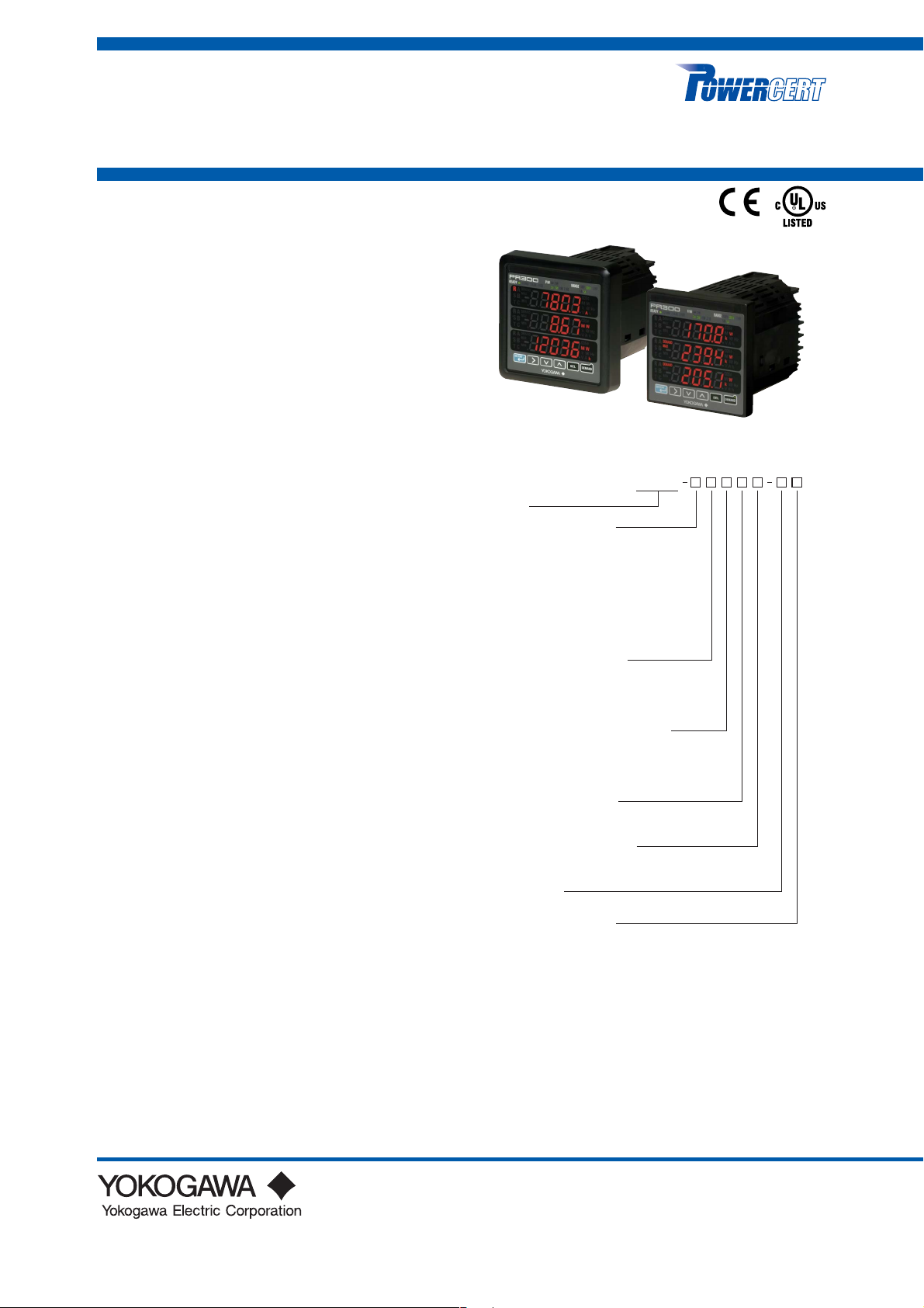
Model PR300
Power and Energy Meter
GS 77C01E01-01E
■ Overview
This panel-mounted power and energy meter with a
large, three-row LED display integrates all the measuring functions required for power management in
locations such as factories and buildings into a single
unit.
With the objective of working toward the preservation
of the global environment by saving energy and
performing equipment maintenance, the PR300 is
designed to display and output the energy of various
types of electrical equipment.
■ Features
• Saves on cost, wiring, and space
Integrates a wide selection of functions for measuring things
like energy (active, regenerative, reactive, and apparent),
power (active, regenerative, reactive, and apparent),
voltage, current, frequency, and power factor into a single
unit.
• Employs a large, three-row LED display
Capable of displaying three-phase current and voltage
simultaneously, and the measurement items you assign.
• Analog output function
Equipped with a transducer function for power (active,
regenerative, reactive, and apparent), voltage, current,
frequency, and power factor (4 to 20 mA DC).
• Demand measurement
Measures the average power and current within a specified
period. It also allows you to set up alarm points to output
alarms.
• Equipped with a multitude of functions
Enables measurement of the maximum and minimum
values of voltage and the maximum value of current, as well
as, for example, the use of external digital input to measure
energy at arbitrary times.
• Pulse output
Capable of outputting pulses proportional to energy (one
measurement item from active, regenerative, reactive, and
apparent energy).
• Converts the phase and wire system of an AC power
system and an input voltage circuit to a universal
format
The PR300 can handle from the single-phase two-wire
system and single-phase three-wire system to the threephase three-wire system and three-phase four-wire system,
and also universally cope with input voltage circuits up to
600 V AC.
• Compatible with ANSI 4-inch round form size and
DIN 96-square instrument size
The ability to attach and detach JIS/ANSI-mounting kit
makes the PR300 compatible with panel cutouts of ANSI 4inch round form, JIS 110-square instrument size, and DIN
96-square instrument size.
•Standard equipped with an RS-485 communication
function and capable of Ethernet communication
• Compatible with overseas requirements
Power line indications A, B, and C provided for overseas
use, in addition to R, S, and T
ANSI 4-inch round form size
DIN 96-square instrument size
The ability to attach and detach JIS/ANSI-mounting kit
ensures compatibility with two sizes.
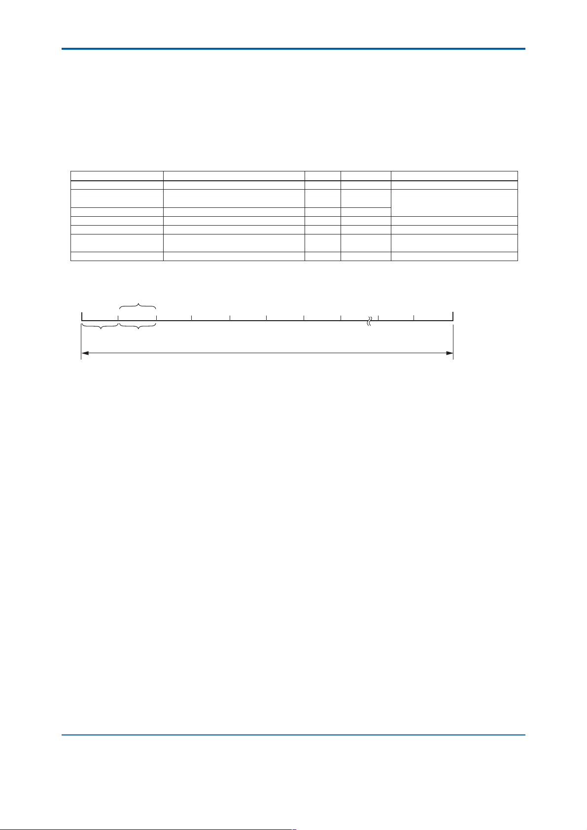
■ Model and Suffix Codes
PR300
Model
Phase and wire system
3:
Universal three-phase three-wire system
(single-phase two-wire, single-phase three-wire,
and three-phase three-wire systems)
4:
Universal three-phase four-wire system
(single-phase two-wire, single-phase
three-wire, three-phase three-wire, and
three-phase four-wire systems)
5: Three-phase four-wire system
(2.5 element)*
Input voltage/input current
1: Universal voltage input*2
(150 V, 300V, 600 V) / 1 A AC
2: Universal voltage input*2
(150 V, 300 V, 600 V) / 5 A AC
Additional input and output function
0: 1 digital input
1: 1 digital input, 1 analog output
2: 1 digital input, 1 pulse output
3:
1 digital input, 1 analog output, 1 pulse output
Communication function
0: RS-485 communication
3:
RS-485 communication, Ethernet communication
Optional measuring function
0: None
3: Demand measurement (1 demand alarm output)
Power supply
6:
100-240 V AC 10% (50/60 Hz) or 130-300 V DC 15%
Phase indication format
A: A, B, and C indications
R: R, S, and T indications
1 In cases where
*
specified, the input current specification of 1 A AC is not applicable.
(PR300-51xxx-xx-0 cannot be ordered.)
Can be used only when the voltage is in a state of equilibrium.
The phase and wire system cannot be changed.
2 Set the voltage range (150 V, 300 V, or 600 V) according to the
*
rated input voltage to be measured.
Voltage” of the Input Specifications on page 6.)
3 For Ethernet communication, the RS-485 communication interface
*
is exclusively for the Ethernet-serial gateway function.
1
“Three-phase four-wire system (2.5 element)” is
3
*
(Refer to “Rated Input
■Ordering Information
Specify the model and suffix codes.
Example: PR300-31000-6A-0
-0
GS 77C01E01-01E
©Copyright Apr. 2006 (KP)
5th Edition Dec. 10, 2008 (KP)
Page 2

<<Contents>> <<Index>>
■Measuring Functions
Measurement item
Active energy () *1 ✔ ✔ ✔ ✔ ✔ kWh, MWh
Active energy () *
Reactive energy () *
Reactive energy () *
Apparent energy *
Optional active energy *
Instantaneous
Single-phase
two-wire
system
1
✔ ✔ ✔ ✔ ✔ kWh, MWh Regenerative energy
1
✔ ✔ ✔ ✔
1
✔ ✔ ✔ ✔
1
✔ ✔ ✔ ✔
1
✔ ✔ ✔ ✔ ✔ Wh
Single-phase
three-wire
system
Three-phase
three-wire
system
Three-phase
four-wire
system
Active power Maximum ✔ ✔ ✔ ✔ ✔ W, kW, MW
Minimum
Instantaneous
Reactive power Maximum ✔ ✔ ✔ ✔
Minimum
Apparent power
Instantaneous
Maximum ✔ ✔ ✔ ✔
Minimum
Instantaneous
Voltage-1 Maximum ✔ ✔ ✔ ✔ ✔ V, kV
Minimum
Instantaneous
Voltage-2 Maximum ✔ ✔ V, kV
Minimum
Instantaneous
Voltage-3 Maximum ✔ ✔ ✔ V, kV
Minimum
Instantaneous
Instantaneous
Instantaneous
Instantaneous
✔ ✔ ✔ ✔
✔ ✔ A, kA
✔ ✔
Current-1
Maximum
Current-2
Maximum
Current-3
Maximum
Frequency Maximum ✔ ✔ ✔ ✔ ✔ Hz
Minimum
Instantaneous
Power factor Maximum ✔ ✔ ✔ ✔
Minimum
2
*
Demand current-1
Maximum ✔ ✔ ✔ ✔
Demand current-2
Maximum ✔ ✔ A, kA
Demand current-3
Maximum ✔ ✔
Demand current
Demand power
*1 Integrated low-cut power can be set for each energy.
Integrated low-cut power: This is a function for not integrating power less than a set value as energy.
The setting range of integrated low-cut power is 0.05 to 20.00% of the rated power (initial value: 0.05%).
*2 Either demand power or demand current can be set as a measurement item.
*3 Can be used only when the voltage is in a state of equilibrium.
*4 Can be measured only when the current is in a state of equilibrium.
Demand
✔ ✔ ✔ ✔
Demand
✔ ✔ A, kA
Demand
✔ ✔
2
Demand
*
Maximum ✔ ✔ ✔ ✔ ✔ W, kW, MW
✔ ✔ ✔ ✔ ✔ W, kW, MW
Three-phase
four-wire system
(2.5 element)
4
*
4
*
4
*
4
*
4
*
4
*
4
*
4
*
4
*
4
*
4
*
4
*
Unit and
symbol
3
*
kvarh, Mvarh LAG:
kvarh, Mvarh LEAD:
kVAh, MVAh
var, kvar, Mvar
VA, kVA, MVA
A, kA
A, kA
COS
A, kA
A, kA
A, kA
A, kA
Remarks
Calculated from the
voltage-1
LAG:
LEAD:
2
✔: Effective
: Ineffective
All Rights Reserved. Copyright © 2006, Yokogawa Electric Corporation
GS 77C01E01-01E 5th Edition Dec. 10, 2008-00
Page 3
<<Contents>> <<Index>>
● Optional integrating function
Power is integrated while a control signal for optional integration is on.
When the control signal is switched from off to on, the optional integrated value indication is reset and integration
starts. (The integrated value prior to the reset is held in a register.) The integrated value cannot be guaranteed in
the event of a power failure occurring during integration.
● Demand measurement (when demand measurement is specified)
The PR300 measures average power or average current within a set demand period.
The maximum demand value for the demand measuring time is held until the power is turned off, remote reset is
executed, or the next demand measurement is started.
Item Setting Range
Demand power/current
Demand period
Demand alarm mask time* 1 minute to length of demand period 1 minute 1 minute
Demand power alarm point
Demand current alarm point
Alarm release function
Data update interval
* This is the time from the start of the demand period to the set time in which no judgment is made for the alarm (alarm masked). During the
alarm mask time, no maximum demand value is updated and no alarm is output.
Active power, current Active power
10 seconds
1 to 60 minutes
(Demand
1 to 1000 kW 1 kW 100 kW When demand power is selected
1 to 1000 A 1 A 100 A When demand current is selected
Automatic release and manual release
alarm mask time to 60 minutes)
Resolution
1 minute 30 minutes
Automatic
Initial Value Remarks
Demand alarm mask time ⬉ Demand period
release
3
Start
demand
measurement
Average power
(current) update
Demand period (1 period)
Average power
(current) update
Demand measuring time
The maximum demand value for this time is held.
Stop
demand
measurement
All Rights Reserved. Copyright © 2006, Yokogawa Electric Corporation GS 77C01E01-01E 5th Edition Dec. 10, 2008-00
Page 4
<<Contents>> <<Index>>
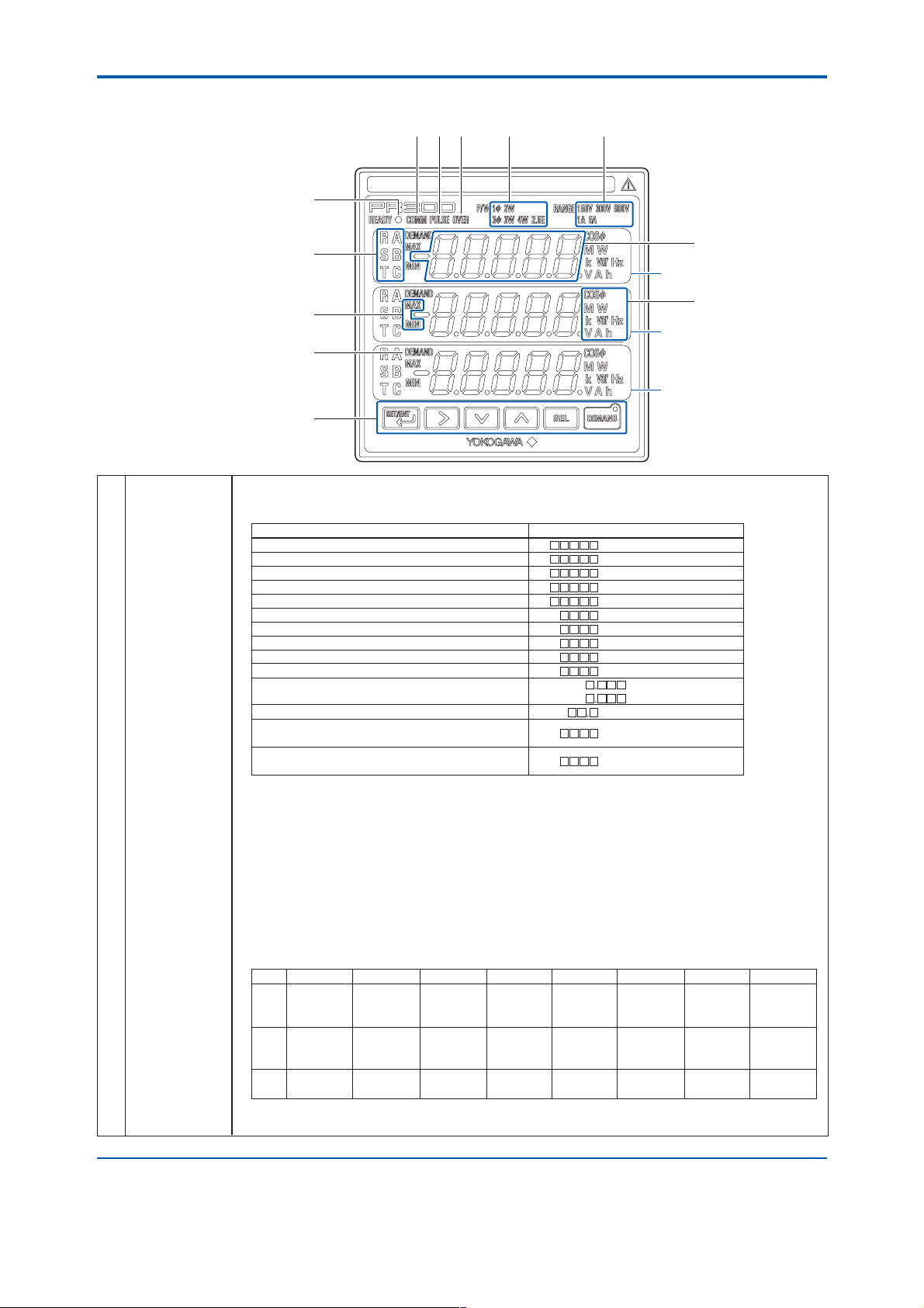
■ Display and Operation Specifications
(7)(6) (8) (9) (10)
(5)
4
Measured
(1)
Value Display
<Continued on the
following page>
(4)
(1)
Upper display
(2)
(3)
Middle display
(11)
Lower display
(12)
5-digit, 3-row, 7-segment LED display
Display color: red
Measured Value display:
Measurement Item Display
Active energy [kWh, MWh] *1
Reactive energy [kvarh, Mvarh] *2
Apparent energy [kVAh, MVAh] *1
Regenerative energy [kWh, MWh] *2
Optional active energy [Wh]
Active/regenerative power (instantaneous, maximum, and minimum values)
Reactive power (instantaneous, maximum, and minimum values)
Apparent power (instantaneous, maximum, and minimum values)
Voltage (instantaneous, maximum, and minimum values)
Current (instantaneous and maximum values) [A, kA] *2, *4
Power factor (instantaneous, maximum,
and minimum values)
Frequency (instantaneous, maximum, and minimum values)
Demand power
Maximum demand power
Demand current
Maximum demand current
*1: Without sign, but with a decimal point
*2:
With a sign and a decimal point ("+" is not indicated). Regenerative power (energy) always shows "−" negative
indication.
*3: "MAX" lights up for the maximum value and "MIN" lights up for the minimum value.
*4: "MAX" lights up for the maximum value.
Measured Value screen:
Display pattern: The measurement items you want to display are assigned to each of the upper, middle, and lower displays
Number of display patterns: Can be set in the range of 1 to 8. Pressing the SET/ENT key switches the display from
Display Pattern-1 Display Pattern-2 Display Pattern-3 Display Pattern-4 Display Pattern-5 Display Pattern-6 Display Pattern-7 Display Pattern-
Upper
display
Middle
display
Lower
display
* The display of current (phase switch indication) is switched between current-1, current-2, and current-3 each time the SEL key is
Current
(Phase switch
indication)*
Voltage
(Phase switch
indication)*
Active power
pressed. The display of voltage (phase switch indication) is switched between voltage-1, voltage-2, and voltage-3 each time the SEL key
is pressed.
LAG: G [COS]
The position of a decimal point differs depending on the primary rated power, VT ratio, and CT ratio.
to provide indications using three display rows as one pattern. Up to eight display patterns can be set.
The initial values are as shown in the following table. (Combinations other than those shown in the
following table are also available if the parameters are set.)
"display pattern-1," "display pattern-2," and so on in order according to the number of patterns set. The
initial value is "1" and only display pattern-1 is displayed when this value is set.
Active power
Reactive
power
Power factor
LEAD: d [COS]
Active energy
LEAD reactive
energy
Apparent
energy
[W, kW, MW] *2, *3
[var, kvar, Mvar] *2, *3
[VA, kVA, MVA] *1, *3
[V, kV] *1, *3
*3
[Hz] *3
[W, kW, MW] [DEMAND] *4
[A, kA] [DEMAND] *4
Current-1
Current-2
Current-3
Voltage-1
Voltage-2
Voltage-3
Current
(Phase switch
indication)*
Voltage
(Phase switch
indication)*
Frequency
Current
(Phase switch
indication)*
Active power
Power factor
8
Active power
Maximum
demand value
Demand
value
All Rights Reserved. Copyright © 2006, Yokogawa Electric Corporation
GS 77C01E01-01E 5th Edition Dec. 10, 2008-00
Page 5
<<Contents>> <<Index>>
VT ratio/CT ratio:
If the VT ratio and CT ratio are set, input to the PR300 is displayed after converting it to the primary input value before VT
or CT. The VT and CT ratios can be set via communication or using the operation keys.
VT ratio setting range: 1 to 6000*
CT ratio setting range: 0.05 to 32000*
* Set the VT ratio and CT ratio so that [secondary rated power] [VT ratio] [CT ratio] is smaller than 10 GW.
(2) Unit Lamps The relevant unit lamp lights up according to a measurement item and measured value.
Display color: red
(3)
MAX and MIN Lamps
(4)
Phase Indication Lamps
should be specified in accordance with the suffix code.)
Display color: red
* Can be measured only when the current is in a state of equilibrium.
(5) Power Lamp Lights up when power is supplied.
Blinks (4 times/sec) until it returns to normal when the communication error occurs.
(6)
Communication Lamp
Display color: green
(7) Pulse Output Lamp
Display color: green
(8)
Demand Alarm Lamp
lights up to indicate the occurrence of an alarm.
Display color: red
(9) Phase and Wire The lamps of the phase and wire system that have been set light up.
System Lamps Display color: green
(10) Input Range Lamps The input voltage range (150 V, 300 V, or 600 V) and input current range (1 A or 5 A) that have been set light up.
Display color: green
(11) DEMAND Lamp Lights up when a demand value is displayed.
Display color: red
(12) Operation Keys
Indicator-out Mode Setting
The ON/OFF setting of the indicator-out mode function and the wait time before entering the indicator-out mode can
be set using the operation keys. (Cannot be set via communication.)
Indicator-out mode: ON/OFF (
Indicator-out mode wait time: 1 to 60 minutes (resolution: 1 minute) (
A/D Sampling Rate,
A/D sampling rate: 4.8 kHz
Data Update Interval
Internal measurement data: display/communication data is updated at an interval of 1 second or less
Either the MAX or MIN lamp lights up when a maximum or minimum measured value is displayed.
Display color: red
Indicate the phase to which the measured value corresponds. (The A, B, and C indications or R, S, and T indications
Phase and Wire System Voltage-1 Voltage-2 Voltage-3 Current-1 Current-2 Current-3
Single-phase two-wire system A (R) − − A (R) − −
Single-phase three-wire system
Three-phase three-wire system
Three-phase four-wire system A (R) B (S) C (T) A (R) B (S) C (T)
Three-phase four-wire system
(2.5 element)
Display color: green
Blinks during communication (RS-485 or Ethernet).
Lights up when output is produced during pulse output, and goes out when no output is produced.
If a demand value exceeds the demand alarm point at a time other than during the alarm mask time, the OVER lamp
Used to switch measured value display patterns.
This key is also used for setting parameters.
Used to move the display digit during energy indication.
This key is also used for setting parameters.
Used to display the maximum or minimum measured value.
These keys are also used for setting parameters.
Used to switch phase indications when the PR300 displays a voltage or current for which phase indication can be
changed. (Phase switch indication is not available for single-phase two-wire system.)
This key is also used for setting parameters.
Used to start/stop demand measurement.
The lamp in the key lights up during demand measurement. Display color: green
This function turns off LEDs after a certain time elapses, with the exception of the power lamp (LED).
A, B (R, S) B, C (S, T) − A (R) C (T) −
A, B (R, S) − B, C (S, T) A (R) − C (T)
A (R) − C (T) A (R)* − C (T)*
initial value: OFF)
initial value: 10 minutes)
5
All Rights Reserved. Copyright © 2006, Yokogawa Electric Corporation GS 77C01E01-01E 5th Edition Dec. 10, 2008-00
Page 6

<<Contents>> <<Index>>
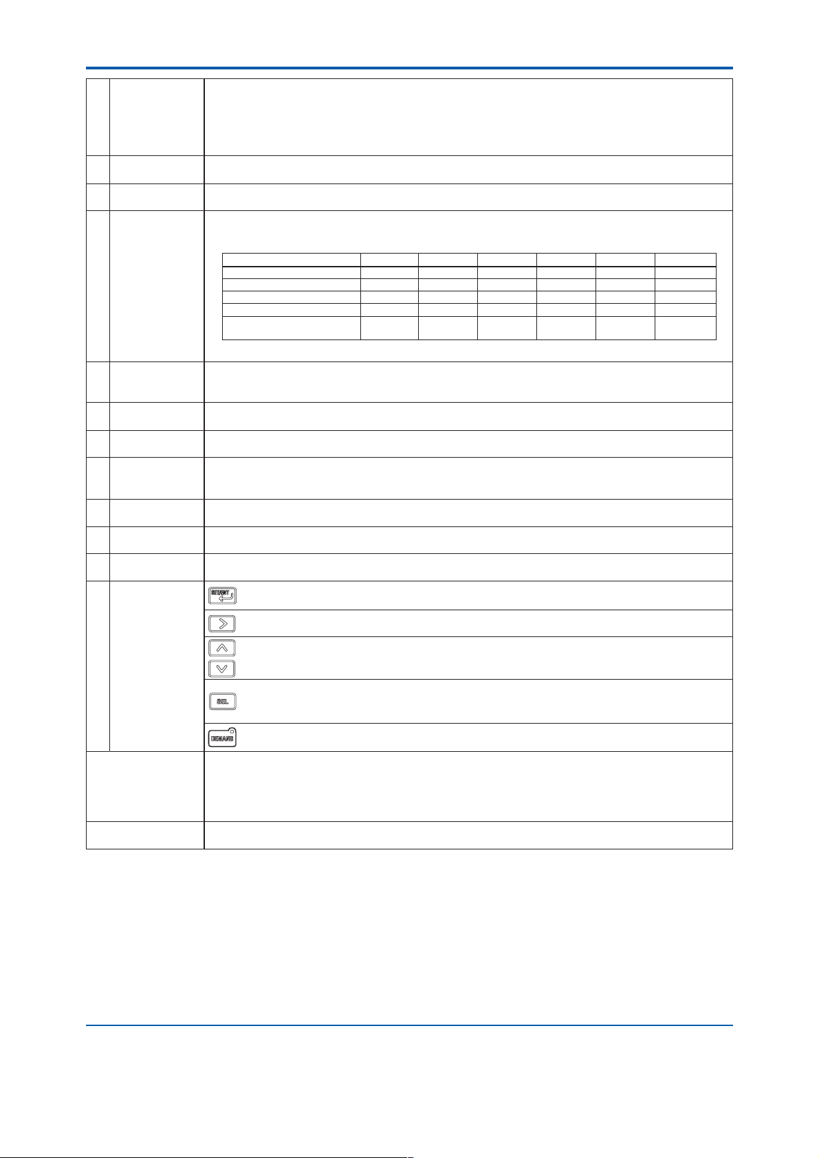
■ Input Specifications
Phase and Wire
System
Frequency
Rated Input Voltage
Rated Input Current
Rated Input Power
and Measuring Range
(When VT and CT are
used, their respective
secondary values)
• Universal three-phase three-wire system (switch the setting from single-phase two-wire system, single-phase three-wire
system, or three-phase three-wire system)
• Universal three-phase four-wire system (switch the setting from single-phase two-wire system, single-phase three-wire
system, three-phase three-wire system, or three-phase four-wire system)
• Three-phase four-wire system (2.5 element)
45 to 65 Hz
Rated V oltage Voltage Range (Variable)
120 V 150 V
240 V 300 V
480 V 600 V
Rated Current Current Range (Fixed)
1 A 1 A
5 A 5 A
• Single-phase two-wire system
Input (AC)
120V/1A
120V/5A
240V/1A
240V/5A
480V/1A
480V/5A
• Three-phase three-wire system
Input (AC)
120V/1A
120V/5A
240V/1A
240V/5A
480V/1A
480V/5A
• Input measuring range when VT and CT are used
The primary input power (Secondary rated power 1.2 VT ratio CT ratio) is smaller than 10 GW and the
value calculated by the following equation is within the input measuring range mentioned above.
Input
Rated
Power
100 W
500 W
200 W
1000 W
400 W
2000 W
Rated
Power
200 W
1000 W
400 W
2000 W
800 W
4000 W
Measuring
Range
120 to 120 W
600 to 600 W
240 to 240 W
1200 to 1200 W
480 to 480 W
2400 to 2400 W
Input
Measuring
Range
240 to 240 W
1200 to 1200 W
480 to 480 W
2400 to 2400 W
960 to 960 W
4800 to 4800 W
Input measuring range (W) =
The primary voltage of VT
900 kV
1800 kV
3600 kV
The primary current of CT
32 kA
160 kA
• Single-phase three-wire system
Approximate
Consumed VA
Voltage Current
0.2 VA
0.4 VA
0.2 VA
0.8 VA
Approximate
Consumed VA
Voltage Current
0.2 VA/
phase
0.4 VA/
phase
0.8 VA/
phase
0.2 VA/
phase
*
*
*
*Input specification of 1 A AC is not available for 2.5 element.
Primary input power (W)
VT ratio CT ratio
Allowable Input Voltage
Allowable Input Current
1.2 times the current range (continuous)
Twice the current range (10 seconds) or
10 times the current range (3 seconds)
Input (AC)
240V / 1A
240V / 5A
Rated
Power
200 W
1000 W
Input
Measuring
Range
240 to 240 W
1200 to 1200 W
• Three-phase four-wire system
Input (AC)
120V / 1A
120V / 5A
240V / 1A
240V / 5A
480V / 1A
480V / 5A
Rated
Power
300 W
1500 W
600 W
3000 W
1200 W
6000 W
Input
Measuring
Range
360 to 360 W
1800 to 1800 W
720 to 720 W
3600 to 3600 W
1440 to 1440 W
7200 to 7200 W
150 V
300 V
600 V
Approximate
Consumed VA
Voltage Current
0.2 VA/
phase
Approximate
Consumed VA
Voltage Current
0.2 VA/
phase
0.4 VA/
phase
0.8 VA/
phase
0.2 VA/
phase
0.2 VA/
phase
6
■ Digital Input Specifications
For digital input, either the optional integration start/stop or the demand alarm release can be used.
If demand measurement is specified for an optional measuring function, digital input enters demand alarm release
status. In this case, the optional integration start/stop cannot be used.
● Control signal for optional integration
Starts or stops optional integration.
Function
Number of Inputs
Input Signal
ON signal: 4.5 to 25 V DC
OFF signal: within 1 V DC
Minimum ON time 50 ms
* A special order can be placed for no-voltage contact.
Note: Optional integration control is also possible via communication.
Once control is performed by digital input, only digital input-based control is available. Communication-based control is no longer
possible until the power is turned off/on or remote reset is executed.
● Demand alarm release (when demand measurement is specified)
Function Cancels demand alarm.
Number of Inputs
Input Signal
ON signal:4.5 to 25 V DC
OFF signal: within 1 V DC
Minimum ON time 50 ms
* A special order can be placed for no-voltage contact.
All Rights Reserved. Copyright © 2006, Yokogawa Electric Corporation
1
Voltage signal*
1
Voltage signal*
GS 77C01E01-01E 5th Edition Dec. 10, 2008-00
Page 7

<<Contents>> <<Index>>
■ Analog Output Specifications (When Analog Output is Specified)
Function Converts measurement data into DC current for output.
Measurement Item for Output
power factor, and frequency
Output Signal 4 to 20 mA DC
Output Accuracy Measurement accuracy of measurement item for output (0.5% of F.S.)
Allowable Load Resistance
Response speed 2 seconds or less (until 1% of the final value is reached)
Setting Item Measurement item for output and the lower and upper limits of scaling.
Active power rated power (W) to rated power (W)
Setting Range of
Reactive power
Lower/Upper Limits
Apparent power 0 to rated power (VA)
of Scaling According to
Voltage (1 to 3) 0 to voltage range (V)
Measurement Item
Current (1 to 3) 0 to current range (A)
for Output
Power factor (LEAD)0.5 to 1 to (LAG)0.5
Frequency 45 to 65 (Hz)
One item selected from active power, reactive power, apparent power, voltage (1 to 3), current (1 to 3),
0 to 600
Initial value: active power (W), lower limit of scaling: 50% (0 W), upper limit of scaling: 100% (maximum value of
Scaling setting condition: upper limit of scaling lower limit of scaling ⭌ 50%
the input measuring range W)
rated power (var) to rated power (var)
■ Pulse Output Specifications (When Pulse Output is Specified)
Function Outputs pulses proportional to energy.
Measurement Item for Output
Number of Outputs 1
Output Signal Open collector
Contact Capacity 30 V DC at 200 mA
Pulse Unit 0.1 to 5000.0 kWh/pulse* (set in 100 Wh increments)
Setting Item Measurement item for output, pulse unit, and ON pulse width
ON Pulse Width Represents the ON time of pulses to be output. (Set the pulse width so that the maximum ON pulse width obtained
by the following equation is not exceeded.)
Within the range of 10 to 1270 ms (set in 10 ms increments)
* The units are kvarh/pulse for reactive energy and kVAh/pulse for apparent energy.
One item selected from active energy, regenerative energy, reactive energy (LEAD, LAG), and apparent energy
Initial value: active energy (kWh), pulse unit: 1 kWh/pulse, and ON pulse width: 50 ms
Maximum ON pulse width (ms) =
Secondary rated power [W] VT ratio CT ratio 1.2 2
Pulse unit [kWh/pulse]* 3600 1000
2
7
■ Demand Alarm Output Specifications (When Demand Measurement is
Specified)
Function
Output Signal
Contact Capacity
Alarm Release Function
* Refer to “Demand alarm release” of the Digital Input Specifications.
Outputs an alarm if the measured demand value exceeds the set demand alarm point.
Open collector
30 V DC at 200 mA
Automatic release: Cancels the alarm if demand falls below the demand alarm point when the next measurement is
performed.
Manual release*: Holds the status of an alarm that occurred once. Cancels the alarm by digital input or the operation
key, or via communication.
All Rights Reserved. Copyright © 2006, Yokogawa Electric Corporation GS 77C01E01-01E 5th Edition Dec. 10, 2008-00
Page 8

<<Contents>> <<Index>>
■ Communication Specifications
● RS-485 communication
Example:
PC
Maximum communication distance: 1200 m
Maximum number of slave stations to be connected: 31
Station number 01 Station number 02 Station number 31
Function RS-485 communication enables you to use the command/response method to read a variety of measurements and
write various settings.
Protocol PC link (with checksum, without checksum), Modbus (RTU, ASCII), PR201 original
Transmission Distance Approx. 1200 m maximum (when 24 AWG twisted-pair cable is used)
Connection Method Multi-drop connection (a maximum of 32 units [including a higher-level device])
Station Number 01 to 99 (maximum number of units to be connected: 31 [number of units that can be connected to a PC etc.])
(Setting range: 01 to 31 is recommended)
Transmission Method Half-duplex communication
Synchronization Method Start-stop synchronization
Baud Rate 19200, 9600, and 2400 bps
Xon/Xoff Control None
Data Format Data length 8 bits, 7 bits
Parity None, even, odd
Stop bit 1 bit, 2 bits
For details, refer to the user’s manual for communications of each device to be connected.
(Note 1) The settings cannot be written.
(Note 1)
8
Example of Connection Diagram
RS-232C
straight
cable
PC
120 Ω (external resistor)
*
Use the external resistor
without using the built-in
resistor of ML2.
Notes:
The PR300 employs a two-wire system for RS-485 communication.
SG: The SG terminal is connected to match the signal level of the RS-485 communication line.
FG: All shielded wires must be connected and then grounded at one place to provide noise protection for
RS-485 communication lines.
All Rights Reserved. Copyright © 2006, Yokogawa Electric Corporation
ML2
RS-232C/RS-485
Converter
(Yokogawa)
(A)
(B)
(SG)
*
PR300 PR300 PR300
Approx. 1200 m maximum (31 units maximum)
(B)(A)(B)(A)
(SG)(SG)
(FG)
GS 77C01E01-01E 5th Edition Dec. 10, 2008-00
120⍀ (built-in)
(A)
(TERM)
(B)
RS-485RS-485RS-485
(SG)
Terminator
Page 9

<<Contents>> <<Index>>
● Ethernet communication (when the Ethernet communication function is specified)
Example:
PC
IP address: 192.168.1.1
HUB
LAN
connection
Ethernet
9
Station number 01
IP address: 192.168.1.2
Function
Ethernet communication enables you to use the command/response method to read
a variety of measurements and write various settings.
The PR300 can be connected to IEEE802.3-compliant networks
(10BASE-T/100BASE-TX).
Communication
Specifications
Protocol Modbus/TCP
Access Control CSMA/CD
Station number 01
IP address: 192.168.1.3
Station number 01
IP address: 192.168.1.4
Station number 01
IP address: 192.168.1.5
Application layer
Transport layer
Network layer
Data link layer
Physical layer
Higher-level device (PC etc.)
MODBUS/TCP
TCP, UDP
IP, ICMP, ARP
Ethernet
10BASE-T/100BASE-TX
Baud Rate 10 Mbps/100 Mbps
Maximum Segment Length 100 m (distance between the hub and module)
Maximum Connecting
Configuration
Maximum of 4 levels of cascading (for 10BASE-T) or maximum of 2 levels of cascading (for 100BASE-TX)
(Number of hubs that can be cascade connected)
IP Address IP addresses can be set using the operation keys on the front of the PR300.
Modbus/TCP
03
Function
06
08
16
Overview of
Modbus/TCP
The structure of Modbus/TCP protocol is as follows:
Protocol
Code
Reads data from multiple D registers
Writes data into D register
Performs loopback test
Writes data into multiple D registers
MBAP Header
Function
Function code Data
Capable of reading data from up to 64 registers continuously.
Capable of writing data into one register.
Capable of performing a communication test.
Capable of writing data into up to 32 registers continuously.
PDU
The Modbus Application Protocol Header(MBAP Header) is made of the following seven bytes:
Description
The Simple Protocol Data Unit (PDU) is
the same as Modbus/RTU (Modbus
protocol via serial communication).
Byte No 0 1 2 3 4 5 6
Description Transaction ID Protocol ID Number of bytes Unit ID
Transaction ID:
Set any value for identifying the transaction. The PR300 returns a value received from a higher-level device as a response.
Protocol ID: Specify "0" for the Modbus/TCP protocol.
Number of bytes: Number of bytes after the unit ID (byte number 6)
Unit ID: The PR300 returns a value received from a higher-level device as a response.
Ethernet-
Serial Gateway
Function
The PR300 has an RS-485 communication terminal in
addition to an Ethernet communication connector.
Modbus/TCP commands received by Ethernet are relayed
to the RS-485 terminal. This enables the PR300 to connect
to a device with an RS-485 communication function
(Modbus/RTU protocol) via a network.
Example:
Higher-level device
IP address: 192.168.1.1 (arbitrary)
Ethernet
10BASE-T/100BASE-TX
RS-485 communication
Protocol Modbus/RTU
Baud Rate
9600 bps
Parity Even, odd, or none
Stop Bit 1 bit
(with Ethernet communication
PR300
function)
RS-485 connection
Station number 01 (fixed)
IP address: 192.168.1.2
(arbitrary)
Data Length 8 bits
RS-485 serial
communication device
Power monitor of POWERCERT Series
Digital indicating controller of
GREEN Series
Signal conditioner of JUXTA Series
Station number 02
(arbitrary)
Station number 10
For details, refer to the user’s manual for communications of each device to be connected.
Note: If Ethernet communication is used, the RS-485 communication interface is used specifically for the Ethernet-serial gateway function.
Therefore, it is not possible for a higher-level device such as a PC to access the PR300 via the RS-485 communication interface.
(arbitrary)
All Rights Reserved. Copyright © 2006, Yokogawa Electric Corporation GS 77C01E01-01E 5th Edition Dec. 10, 2008-00
Page 10

<<Contents>> <<Index>>
■ Standard Performance
Accuracy Rating
Calculation Accuracy
Backup upon Power Failure
Insulation Resistance
Withstand Voltage
Impulse Withstand Voltage
Effects of Magnetic Field
Effects of Changes in Ambient
Temperature
Effects of Power Supply Voltage
Variations
Effects of Input Frequency
Power Supply
Power Consumption
Active energy/optional active energy (Wh)
Active power (W)
Voltage (V)
Current (A)
Frequency (Hz)
Demand
The value is calculated to an accuracy of ±1 digit from the measured value for reactive energy, apparent energy,
reactive power, apparent power, power factor or current*.
* Current is only for the 2.5 element measurement.
The last integrated values obtained immediately before the power failure are held for active energy,
regenerative energy, reactive energy, and apparent energy.
Between each of the voltage input, current input, power,
ground, digital input, pulse output, analog output, RS485
communication output, Ethernet communication output, and
alarm output terminals
Between each of the voltage input, current input, power, and
ground terminals:
Between (the voltage input, current input, power and ground
terminals) and the digital input, pulse output, analog output,
alarm output, RS-485 communication output, and Ethernet
communication output terminals:
Between each of the digital input, pulse output, analog output,
alarm output, and (RS-485 communication output, Ethernet
communication output) terminals:
Between the RS-485 communication output, and Ethernet
communication output terminals:
Between all of the voltage input, current input, and power terminals and the ground terminal:
Between all of the output and ground terminals and all of the voltage input and current input terminals:
6 kV (1.2/50s), 10 times for positive and negative
400 A/m or less Active power: ±0.5% of F.S. Voltage/Current: ±0.25% of F.S.
0.03%/°C for a temperature change rate of 10°C/h or less (when 0.05 In ≤ I ≤ I max, power factor = 1)
0.05%/°C for a temperature change rate of 10°C/h or less (when 0.1 In ≤ I ≤ I max, power factor = LAG 0.5)
In: rated current, I: present current input
Active power: ±0.25%, Voltage/Current: ±0.125%
(for variations within the power supply operating range (when 0.01 In and power factor = 1)) In: rated current
Active power: ±0.25%, Voltage/Current: ±0.125% (for variation of 45 to 65 Hz)
100-240 V AC ±10% (50/60 Hz) or 130-300 V DC ±15%
AC drive: 10 VA maximum, DC drive: 5 W maximum
(EN60687 accuracy: class 0.5 or equivalent)
±0.5%
±0.5% of F.S.
±0.25% of F.S. (voltage rms)
±0.25% of F.S. (current rms)
±0.5 Hz
±0.5%
100 M⍀ or more (at 500 V DC)
2500 V AC for 1 minute
2500 V AC for 1 minute
1000 V AC for 1 minute
500 V AC for 1 minute
10
■ Safety and EMC Standards
Safety Standards
Measurement category
Installation category
Rated measurement input
EMC-compliant Standards
All Rights Reserved. Copyright © 2006, Yokogawa Electric Corporation
Compliant with
IEC/EN61010-1
UL61010-1
CAN/CSA C22.2 No.61010-1-04 (C-UL Listed)
600V CAT. III
Measurement Category
CAT.I
CAT.II
CAT.III
CAT.IV
CAT. II
Pollution degree: 2 (IEC/EN61010-1)
Voltage input:
Current input:
Compliant with EN61326
During testing, the instrument continues to operate at a measurement accuracy within the range of 20%.
600V AC (between terminals)
600V AC (across ground)
Circuits not directly connected to main power supply
Circuits directly connected to low-voltage facility
Circuits in building facilities
Supply sources to low-voltage facilities
Description
Remarks
Home-use equipment, portable tools, etc.
Switchboards, circuit breakers, etc.
Overhead lines, cable systems, etc.
GS 77C01E01-01E 5th Edition Dec. 10, 2008-00
Page 11

<<Contents>> <<Index>>
11
■ Environmental Conditions
Normal Operating Conditions
Warm-up time
Ambient temperature
Temperature change
Ambient humidity
Magnetic field
Continuous vibration
Short-time vibration
Shock
Installation
Mounting position
Installation altitude
Effects on Operating Conditions
Effects of ambient
temperature
Effects on supply
voltage variations
Transport and Storage Conditions
Temperature
Humidity
Shock and dropping of
package
At least 30 minutes
0 to 50°C (reference temperature: 23 2°C)
10°C/h or less
20 to 90% RH (no condensation)
400 A/m or less
10 to 60 Hz, 0.035 mm, 75 minutes
60 to 150 Hz, 4.9 m/s
2
for 15 seconds or less
14.7 m/s
2
or less (for shock time of 11 ms)
98 m/s
Indoor installation only
Vertical surface mounting only
2000 m or less
Analog output: 0.05% of F.S./°C or less
Analog output: 0.05% of F.S./°C or less
20 to 70°C
5 to 95% RH (no condensation)
90 cm (provided that an external packing
box is used)
2
, 75 minutes
■ Initial Settings (Time of Shipment)
The PR300 has the following initial settings at the
time of shipment. Settings can be modified after
delivery.
Setting Item
Phase and wire system
Voltage range
Input
VT ratio
CT ratio
Integrated low-cut power
Station number
Protocol
Baud rate
Parity
Stop bit
Data length
IP address *
Communication
Port number *
Subnet mask *
Default gateway *
2
Measurement item for pulse output
Pulse unit
Pulse
Output *
ON pulse width
Measurement item for analog output
3
Lower limit of scaling
Upper limit of scaling
Analog
Output *
4
Demand power/current
*
Demand period
Demand alarm mask time
Demand power alarm point
Demand current alarm point
Demand
Measurement
Alarm release function
Indicator-out mode/indicator-out
Other
mode wait time
*1 When the Ethernet communication function is specified
*2 When pulse output is specified
*3 When analog output is specified
*4 When demand measurement is specified
1
1
1
1
Initial Value
Three-phase three-wire system
(for three-phase three-wire system)
Three-phase four-wire system
(for three-phase four-wire system)
300 V
1
1.00
0.05 %
01
PC link with checksum
9600 bps
None
1 bit
8 bits
192.168.1.1
502
255.255.255.0
0.0.0.0
Active energy (kWh)
1 kWh/pulse
50 ms
Active power (W)
50% (0 W)
100% (maximum value of the
input measuring range W)
Active power
30 minutes
1 minute
100 kW
100 A
Automatic release
Off/10 minutes
■ Power Items and Equations
Phase and Wire
Syatem
Single-phase
two-wire system
Single-phase
three-wire
system
Three-phase
three-wire
system
Three-phase
four-wire system
Three-phase
four-wire system
(2.5 element)
* For distorted wave input, there may be differences between the PR300 and a
measuring instrument that uses a different measurement principle.
Apparent Power
VA= VA
VAi= ViAi
i=1, 2
⌺VA= VA1+VA2
VAi= ViAi
i= 1, 3
⌺VA= 3 /2(VA1+VA3)
VAi= ViAi
i=1, 2, 3
⌺VA= VA1+VA2+VA3
VAi= ViAi
i= 1, 3
⌺VA= 3 /2(VA1+VA3)
Reactive Power
(without using reactive
power meter method)
Q= ((VA)
Qi= ((VAi)2Pi2)
⌺Q = Q1+Q2
Qi= ((VAi)2Pi2)
⌺Q = Q1+Q3
Qi= ((VAi)2Pi2)
⌺Q = Q1+Q2+Q3
Qi= ( 3 /2(VAi)2Pi2)
⌺Q = Q1+Q3
(V and A are rms values)
2P2
i= 1, 2
i= 1, 3
i= 1, 2, 3
i= 1, 3
Power Factor
)
⌺P/⌺VA
(without using
reactive
power meter
method)
■ Mounting and Shape
Materials
Mounting Method
Connection Method
External Dimensions
(including a terminal cover)
Weight
Casing: polycarbonate resin (PC), UL94 V-0
Terminal block: polybutylene terephthalate (PBT),
Terminal cover: polyamide resin (PA6), UL94 V-2
Panel mounting (refer to Panel Cutout
Dimensions)
M3 screws for terminal connections:
analog output, pulse output, demand alarm output,
digital input, and RS-485 communication
M4 screws for terminal connections:
voltage/current input and power supply
RJ45 connection: Ethernet communication
110(H) 110(W) 128(D) mm or
96(H) 96(W) 126(D) mm
Approx. 600 g (when the accessories such as
mounting bracket are attached)
UL94 V-0
■ Accessories
JIS/ANSI-mounting kit
DIN-mounting bracket
Dust cover (with a screw)
Terminal cover (with screws)
Shorting bar (for RS-485 communication termination)
Tag number label
1 set
2
1
1
1
2
All Rights Reserved. Copyright © 2006, Yokogawa Electric Corporation GS 77C01E01-01E 5th Edition Dec. 10, 2008-00
Page 12

<<Contents>> <<Index>>
■ Connection Diagrams
A phase and wire system can be selected by specifying the parameters.
If measurement input does not exceed 600 V AC or 5A AC, direct input without using a VT or CT is possible. Do not
ground the input circuit when a VT or CT is not used. Perform wiring for the voltage and current in the same circuit.
● Single-phase two-wire system
12
Power-source side
12
k
K
CT
L
l
Load side
Fuse
UVu
VT
Pulse output
13
14
v
Contact capacity:
30V DC, 200mA
1S
1L
P1
P2
1
23
45
6
7
9
8
10
Analog output
11
12
17
11
18
12
19
13
20
14
21
15
22
16
Demand alarm output
ALM
15
CAUTION
Screws marked with ● are an essential part
of the structure. For safety reasons, do not
touch them.
*1: If Ethernet communication is used, the RS-485 communication
interface is used specifically for the Ethernet-serial gateway function.
*2: If demand measurement is specified, the demand alarm release is selected.
16
ALM
Output signal:
4 to 20mA DC
23
24
25
LED
LED
Contact capacity:
30V DC, 200mA
(resistive load)
RS-485 communication*
TERM
17
R: 120⍀ (built-in)
R
A
18
19
20
When terminating on wiring,
short-circuit terminals and .
B
SG
RS-485
1
18
17
Power supply
L
23
Power supply
N
24
PE
25
Operating range:
100-240V AC 10% or
130-300V DC 15%
Optional integration control signal
or demand alarm release
DI
21
DI
22
Voltage signal
ON signal: 4.5 to 25V DC
OFF signal: within
1V DC
2
*
Ethernet communication
RJ45 connector
10BASE-T/100BASE-TX
Link LED (top)
Color Description
Off Stopped
Orange
10Mbps
Green 100Mbps
Switching between 10BASE-T and 100BASE-TX takes place automatically.
Switching between half duplex and full duplex takes place automatically.
Active LED (bottom)
Color
Description
Off Stopped
Orange Half duplex
Green
Full duplex
All Rights Reserved. Copyright © 2006, Yokogawa Electric Corporation
GS 77C01E01-01E 5th Edition Dec. 10, 2008-00
Page 13

<<Contents>> <<Index>>
● Single-phase three-wire system
13
Power-source side
1N2
k
K
CT
L
l
k
K
CT
L
l
Load side
Pulse output
13
14
Contact capacity:
30V DC, 200mA
Analog output
11
12
17
1
23
45
6
7
9
8
10
Fuse
1S
1L
2S
2L
U
u
P1
V
V
U
VT
P0
v
P2
v
u
CAUTION
Screws marked with ● are an essential part
of the structure. For safety reasons, do not
touch them.
*1: If Ethernet communication is used, the RS-485 communication
interface is used specifically for the Ethernet-serial gateway function.
*2: If demand measurement is specified, the demand alarm release is selected.
11
18
12
19
13
20
14
21
15
22
16
Demand alarm output
ALM
15
ALM
16
Output signal:
4 to 20mA DC
23
24
25
LED
LED
Contact capacity:
30V DC, 200mA
(resistive load)
RS-485 communication*
TERM
17
R: 120⍀ (built-in)
R
A
18
19
20
When terminating on wiring,
short-circuit terminals and .
B
SG
RS-485
1
18
17
Power supply
L
23
Power supply
N
24
PE
25
Operating range:
100-240V AC 10% or
130-300V DC 15%
Optional integration control signal
or demand alarm release
DI
21
DI
22
Voltage signal
ON signal: 4.5 to 25V DC
OFF signal: within
1V DC
2
*
Ethernet communication
RJ45 connector
10BASE-T/100BASE-TX
Link LED (top)
Color Description
Off Stopped
Orange
10Mbps
Green 100Mbps
Switching between 10BASE-T and 100BASE-TX takes place automatically.
Switching between half duplex and full duplex takes place automatically.
Active LED (bottom)
Color
Description
Off Stopped
Orange Half duplex
Green
Full duplex
● Three-phase three-wire system
U
V
V
U
VT
Pulse output
13
14
u
v
v
u
1S
1L
3S
3L
P1
P2
P3
Contact capacity:
30V DC, 200mA
Power-source side
123
A
(R)B(S)C(T)
K
k
CT
L
l
k
K
CT
L
l
Fuse
Load side
CAUTION
Screws marked with ● are an essential part
of the structure. For safety reasons, do not
touch them.
*1: If Ethernet communication is used, the RS-485 communication
interface is used specifically for the Ethernet-serial gateway function.
*2: If demand measurement is specified, the demand alarm release is selected.
1
23
45
6
7
9
8
10
Analog output
11
12
17
11
18
12
19
13
20
14
21
15
22
16
Output signal:
4 to 20mA DC
23
24
25
LED
LED
Demand alarm output
ALM
15
16
ALM
Contact capacity:
30V DC, 200mA
(resistive load)
RS-485 communication*
TERM
17
R: 120⍀ (built-in)
R
A
18
19
20
When terminating on wiring,
short-circuit terminals and .
B
SG
RS-485
1
18
17
Power supply
L
23
Power supply
N
24
PE
25
Operating range:
100-240V AC 10% or
130-300V DC 15%
Optional integration control signal
or demand alarm release
DI
21
DI
22
Voltage signal
ON signal: 4.5 to 25V DC
OFF signal: within
1V DC
2
*
Ethernet communication
RJ45 connector
10BASE-T/100BASE-TX
Link LED (top)
Color Description
Off Stopped
Orange
10Mbps
Green 100Mbps
Switching between 10BASE-T and 100BASE-TX takes place automatically.
Switching between half duplex and full duplex takes place automatically.
Active LED (bottom)
Color
Description
Off Stopped
Orange Half duplex
Green
Full duplex
All Rights Reserved. Copyright © 2006, Yokogawa Electric Corporation GS 77C01E01-01E 5th Edition Dec. 10, 2008-00
Page 14

<<Contents>> <<Index>>
● Three-phase four-wire system
14
Power-source side
N1
23
A
(R)B(S)C(T)
K
k
CT
L
lk
K
CT
L
l
K
L
Load side
Pulse output
13
14
Contact capacity:
30V DC, 200mA
Analog output
11
12
17
1
23
45
6
7
9
8
10
CT
Fuse
1S
1L
2S
2L
k
l
U
V
U
V
U
V
VT
3S
3L
P1
u
P0
v
P2
u
v
P3
u
v
CAUTION
Screws marked with ● are an essential part
of the structure. For safety reasons, do not
touch them.
*1: If Ethernet communication is used, the RS-485 communication
interface is used specifically for the Ethernet-serial gateway function.
*2: If demand measurement is specified, the demand alarm release is selected.
11
18
12
19
13
20
14
21
15
22
16
Demand alarm output
ALM
15
ALM
16
Output signal:
4 to 20mA DC
23
24
25
LED
LED
Contact capacity:
30V DC, 200mA
(resistive load)
RS-485 communication*
TERM
17
R: 120⍀ (built-in)
R
A
18
19
20
When terminating on wiring,
short-circuit terminals and .
B
SG
RS-485
1
18
17
Power supply
L
23
Power supply
N
24
PE
25
Operating range:
100-240V AC 10% or
130-300V DC 15%
Optional integration control signal
or demand alarm release
DI
21
DI
22
Voltage signal
ON signal: 4.5 to 25V DC
OFF signal: within
1V DC
2
*
Ethernet communication
RJ45 connector
10BASE-T/100BASE-TX
Link LED (top)
Color Description
Off Stopped
Orange
10Mbps
Green 100Mbps
Switching between 10BASE-T and 100BASE-TX takes place automatically.
Switching between half duplex and full duplex takes place automatically.
Active LED (bottom)
Color
Description
Off Stopped
Orange Half duplex
Green
Full duplex
● Three-phase four-wire system (2.5 element)
Power-source side
N1
23
A
(R)B(S)C(T)
K
k
CT
L
lk
K
CT
L
l
K
L
Load side
k
CT
l
Fuse
*1: If Ethernet communication is used, the RS-485 communication
interface is used specifically for the Ethernet-serial gateway function.
*2: If demand measurement is specified, the demand alarm release is selected.
Pulse output
13
14
Contact capacity:
30V DC, 200mA
1S
1L
2S
2L
3S
3L
UVu
V
U
P1
P0
v
P3
v
u
VT
CAUTION
Screws marked with ● are an essential part
of the structure. For safety reasons, do not
touch them.
1
23
45
6
7
9
8
10
Analog output
11
12
17
11
18
12
19
13
20
14
21
15
22
16
Output signal:
4 to 20mA DC
23
24
25
LED
LED
Demand alarm output
ALM
15
16
ALM
Contact capacity:
30V DC, 200mA
(resistive load)
RS-485 communication*
TERM
17
R: 120⍀ (built-in)
R
A
18
19
20
When terminating on wiring,
short-circuit terminals and .
B
SG
RS-485
1
18
17
Power supply
L
23
Power supply
N
24
PE
25
Operating range:
100-240V AC 10% or
130-300V DC 15%
Optional integration control signal
or demand alarm release
DI
21
DI
22
Voltage signal
ON signal: 4.5 to 25V DC
OFF signal: within
1V DC
2
*
Ethernet communication
RJ45 connector
10BASE-T/100BASE-TX
Link LED (top)
Color Description
Off Stopped
Orange
10Mbps
Green 100Mbps
Switching between 10BASE-T and 100BASE-TX takes place automatically.
Switching between half duplex and full duplex takes place automatically.
Active LED (bottom)
Color
Description
Off Stopped
Orange Half duplex
Green
Full duplex
All Rights Reserved. Copyright © 2006, Yokogawa Electric Corporation
GS 77C01E01-01E 5th Edition Dec. 10, 2008-00
Page 15

<<Contents>> <<Index>>
■ External Dimensions
● ANSI 4-inch round form size (when a bezel is attached)
15
110
110 109
Bezel
(for ANSI-mounting)
22
2
(126.5) (109)
104.5
Dust cover
2-M5
1 to 10
23
(Acceptable panel thickness for mounting)
1.5
Terminal cover
<Panel Cutout Dimensions>
ANSI
42.9±0.4
(1.688±0.015)
42.9±0.4
(1.688±0.015)
42.9±0.4
(1.688±0.015)
ø101.6
(ø4.000)
Unit: mm
(approx. inch)
Unit: mm
42.9±0.4
(1.688±0.015)
Multiple Mounting
ø7.9
(ø0.312)
160 min.
(6.299 min.)
160 min.
(6.299 min.)
Normal Allowable Deviation= ±(Value of JIS B 0401-1999 tolerance grade IT18)/2
All Rights Reserved. Copyright © 2006, Yokogawa Electric Corporation GS 77C01E01-01E 5th Edition Dec. 10, 2008-00
Page 16

<<Contents>> <<Index>>
● DIN 96-square instrument size
16
110
96
96
<Panel Cutout Dimensions>
+0.8
92 (68)
0
(124.5) (109)
12.3
1 to 10
(Acceptable panel
thickness for mounting)
112.2
Dust cover
1.5
Terminal cover
Mounting bracket
2 places
Unit: mm
Unit: mm
109
92
(68)
+0.8
0
Min. 160
Min. 160
Normal Allowable Deviation= ±(Value of JIS B 0401-1999 tolerance grade IT18)/2
All Rights Reserved. Copyright © 2006, Yokogawa Electric Corporation
Subject to change without notice.
GS 77C01E01-01E 5th Edition Dec. 10, 2008-00
 Loading...