

Page 1
User
Manual
Model PR20
Retractable fitting for
combined pH/redox electrodes
IM 12B6K3-E-E
9th Edition
Page 2

IM 12B6K3-E-E
Page 3

CONTENTS
1. GENERAL 2
1-1.Description 2
1-2.Features 2
1-3.Safety precautions 2
2. UNPACKING AND CHECKING 3
2-1.Unpacking and inspection 3
2-2.Mounting location 3
2-3.Specifications 4
2-4.Model and codes 5
2-5.Dimensions 8
3. INSTALLATION AND WIRING 9
3-1.General 9
3-2.Accessories 10
3-3.Preparing the electrode for use 10
3-4.Mounting the electrode 10
3-5.Probe insertion 12
3-6.Adjusting the iinsersion depth 13
3-7.Wiring 13
4. MAINTENANCE 14
4-1.General 14
4-2.Cleaning 14
4-3.Calibration 15
4-4.Replacing the electrode 16
4-5.Replacing the O-rings 16
4-6.Replacing the cable 17
4-7.Flush port connections 17
5. EXPLODED VIEW 19
6. SPARE PARTS LIST 20
IM 12B6K3-E-E
Page 4

2
1. GENERAL
1-1. Description
The retractable fitting with ball-valve
allows a safe insertion and retraction of a combined pH/reference
electrode while the process is
under pressure. It can be mounted
in a variety of positions as long as
the electrode is in an almost vertical
position with the tip pointing downward (see fig. 2-1).
The insertion depth can be selected
on site. A minimum insertion depth
of 0.2 mtr. into the process liquid is
advised to have a fast temperature
response. A special 'memory' ring
is provided to remember the position of the electrode after retraction.
To protect any loss of process
liquid the mechanism for releasing
the probe is designed to operate
only when the ball-valve is closed.
The combined pH/reference electrode can be replaced or calibrated
easily. The especially designed
cable has integrated leads for the
temperature sensor, shielding and
liquid earth. The end is pre-finished
with cable endings for easy mounting to industrial transmitters.
1-2. Features
- A safe "through the valve" insertion and retraction design.
- Additional safety though a special
designed 'T-bar' locking mechanism.
- Maintenance, replacement and
calibration of the electrode without
interruption of the process.
- Adjustable insertion depth for
optimal measuring position in the
process.
- Easy replacement of the electrode.
- Improved sealing and damping by
addition O-rings.
- Integrated liquid earth and temperature sensor (Pt100 or Pt1000 to
IEC 751 or DIN 43760).
- Simplified installation by optional
ball-valves with flanged or tapered
connections.
- Available in two different materials
and two different lengths (0.5 mtr.
and 1 mtr.)
1-3. Safety precautions
The PR20 has been designed to
give maximum safety in operation.
For optimum safety a flanged ballvalve is recommended.
Yokogawa does not accept any
claims or penalties on possible
damages or accidents which occurred by operation of the PR20 fitting.
The installation of the probe is to be
implemented under the local safety
regulations for pressurised vessels
or pipe-lines for retraction or insertion. The instructions given in this
manual must be followed exactly.
IM 12B6K3-E-E
Page 5
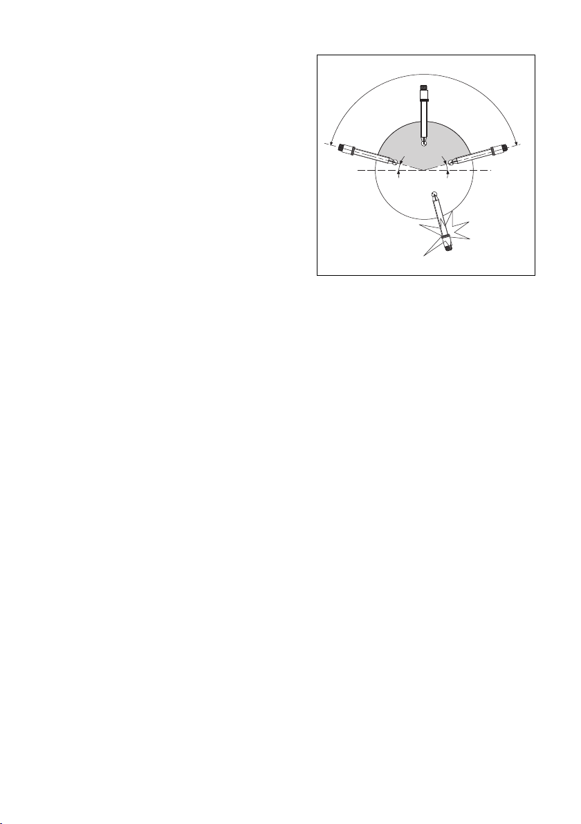
INCORRECT
15º
15º
HORIZONTAL
CORRECT
CORRECT
2. UNPACKING AND CHECKING
2-1. Unpacking and inspection
When you receive the PR20 retractable fitting it is packed in a cardboard box. Open the box and
check that the model code on the
fitting is the same as on the packing list (see §2-4). The model code
with serial number of the fitting are
on an identification plate fixed on
the protection ring.
Also check that the options you
ordered are supplied. These options
are delivered in separate bags.
If you have any problems or
questions, please contact the
nearest Yokogawa service centre or
sales organisation for assistance.
2-2. Mounting location
The PR20 fitting is intended to be
used for in-line pH measurement.
When it is delivered with an optional
ball-valve or when it is used in combination with a locally purchased 1
inch ball-valve, the process does
not need to be interrupted for maintenance of the sensor. The location
can be in a large diameter pipeline
or a vessel. The angle of the fitting
with the horizon should not be less
than 15 degrees (see fig. 2-1).
The pressure- and temperature
ratings of the electrode inside the
fitting determine the maximum
rating of the measurement point.
3
Fig. 2.1. Angle of fitting
Warranty
Yokogawa Europe B.V. warrants
that the goods delivered are made
from new materials to the best
workmanship available. Malfunction
of any of the delivered goods or
parts, can only lead to replacement
of the damaged parts. No claims
can be made to damages or accidents resulting from the use of the
goods. No claims can be made to
the expected or promised performance of the goods under any circumstances.
Damaged goods or parts should be
sent to the local Service organisation for warranty claim purposes.
Yokogawa has the right to deny
warranty claims after investigation
of the data and the materials.
IM 12B6K3-E-E
Page 6

4
2-3. Specifications
Materials (wetted parts)
Probe
Model PR20-S : Stainless steel AISI 316
Model PR20-T : Titanium
O-ring seals : Viton 70° shore
Silicone rubber 50° shore
Non-wetted : Stainless steel (AISI 316) and
parts polyphenylene sulphide (PPS)
1
/
Process conn. : 1
" BSP-female (see modelcode for other connections)
4
Insertion length :The dimensional drawing indicates the maximum
insertion length for both specified probe lengths.
Pressure/temperature ratings
Static conditions : 2 MPa at 20°C, 500 kPa at 125°C
Operating
conditions : max. 500 kPa, max. 100°C
Weight : Approx. 2.5 kg. (SS316 version without ball-valve)
Specification of the optional senors
SC21-AAP26 : 1 to 500 kPa at 0 to 110°C, (pH/ref electrode)
SC21-AGP26 : 1 to 500 kPa at 0 to 110°C, (pH/ref electrode)
SC21-ALP26 : 1 to 500 kPa at 0 to 110°C, (pH/ref electrode)
SC21-AGP24 : 1 to 500 kPa at 0 to 80°C, (pH/ref electrode)
SC29-PTP29 : 1 to 500 kPa at 0 to 110°C, (Redox/ref electrode)
IM 12B6K3-E-E
Page 7

2-4. Model and codes
Model Suffix code Description
PR20 Retractable fitting
Material -S Stainless steel AISI 316
-T Titanium
Probe length*) -05 0.5 mtr.
-10 1 mtr.
Cable length -05 5 mtr.
-10 10 mtr.
Temp. sensor -T1 Pt1000
-T2 Pt100
Style *B Style code
Adapters /YYY See separate table
Certificates /M Material certificate 3.1B according to
EN-10-024 (DIN 50049) on wetted partsa
/T Test certificate for hydrostatic pressure
test (2 MPa at ambient temperature)
Combined /EB SC21-AAP26
electrode /EG SC21-AGP24
/EH SC21-AGP25
* Note: The insertion depth of the probe is given in the dimensional drawing.
5
IM 12B6K3-E-E
Page 8
6
ISO 228/1-G 1
ISO 229/1-G 1 1/4
20 (0.78)
45 (1.77)
ISO 229/1-G 1 1/4
63 (2.55)
65 (2.56)
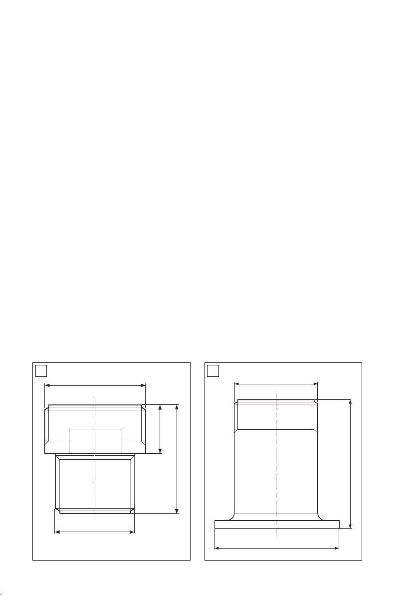
Options
Adapter Option code Drawing
Model PR20-S PR20-T
Adapter only
1" BSP-male /SBS /TBS A
1" NPT-male /SNS /TNS A
DIN flange DN25 PN16 /SDS /TDS B, C
ANSI flange 1" 150 lbs /SUS /TUS B, C
Adapters and ball-valve
1" BSP-female /SBB /TBB A, D
1" NPT-female /SNN /TNN A, D
DIN flange DN25 PN16 /SDD /TDD B, C, E
ANSI flange 1" 150 lbs /SUU /TUU B, C, E
Adapter with flush ports
DIN flange DN25 PN16 /SES /TES F,C
ANSI flange 1" 150 lbs /SVS /TVS
Adapter with flush ports and ball-valve
DIN flange DN25 PN16 /SED /TED F, C, E
ANSI flange 1" 150 lbs /SVU /TVU F, C, E
Weld in adapters
Straight welding /SWR
Angled at 15 degrees /SWA
A B
DR 1 - 11 1/2 NPT acc. ANSI B 1.20.1
IM 12B6K3-E-E
Page 9

l
k
d
D
NW25
D
d
k
l
ø115
ø42.5
ø85
ø14
ø108
ø42.5
ø79.2
ø15.7
1 inch
95 (3.75)
125 (4.9)
65 (2.56)
23 (0.90)
ISO 229/1-G 1 1/4
63 (2.55)
DC
Internal thread (both sides)
ISO 228/1-G 1 OR
1 - 11 1/2 NPT ACC. ANSI B 1201
7
Glanges (both sides)
DN25-PN10 acc. DIN 2642 or
1”-150Lbs acc. ANSI B 16.5
FE
1/8 - 27 NPT vlg. ANSI G 1.20.1
IM 12B6K3-E-E
Page 10

8
ø
48
(ø 1.9)
ø 34
(ø 1.3)
ø 55
(
ø 2.16)
240
(
9.45)
ø 23
(ø 0.90)
390 or 890 (15.35 or 35)
550 or 1050 (21.65 or 41.35)
200 or 700
(7.9 or 27.5)
DIN 85 (3.35)
ANSI: 79.4 (3.125)
125
(4.95)
BSP: 275 or 775 max. (10.85 or 30.5)
NPT: 265 or 765 max. (10.45 or 30.1)
95 (3.75)
ø 48
(ø 1.9)
ø 21
(
ø 0.83)
2-5. Dimensions
mm (inch)
IM 12B6K3-E-E
Page 11

3. INSTALLATION AND WIRING
3-1. General
It is important to have the point of
measurement in a location that is
representing the process composition. Check whether the specifications of the electrode fulfil the maximum occurring process conditions.
The fitting has several optional connection possibilities. Check that you
received the correct size and type.
Install the fitting at a convenient
location for maintenance and calibration. For maintenance or calibration the probe will need a space of
about 2 mtr. for total retraction
(depending on probe length and
optional process adapters and/or
ball-valves). The position of the fitting must be within 15 degrees of
the horizon with the tip pointing
downward (see fig. 2-1). Installation
in a bend of a pipe-line is a good
measurement position.
When inserting the PR20 retractable fitting in a perpendicular position
to the process flow, the flow velocity will put a mechanical force on the
probe. Take care that this force is
not too large. It is recommended to
have the PR20 retractable fitting
positioned at a 45° angle into the
process stream.
9
Fig. 3-1a. Pipe mounting
Fig. 3-1b. Tank mounting
IM 12B6K3-E-E
Page 12

10
ATTENTION
Do not insert the fitting into the process without the electrode mounted! Prevent liquid to come into
contact with the connector plug.
Start with the assembly of the electrode into the probe and follow the
instructions for the preparation of a
new electrode (see §3-3).
3-2. Accessories
Optional accessories are delivered
separately. When a ball-valve is
ordered as an option, this should
be mounted to the measuring position first. When the ball-valve in
place, the process line is secure.
If the ball-valve has a tapered connection, it needs to be locked with
the supplied glue. Next the adapter
at the other side of the ball-valve
needs to be mounted. This adapter
1
has 1
/
" BSPP-male thread at one
4
side and matching connection for
the ball-valve at the other side.
Mount the adapter on the ball-valve
and lock it with the supplied glue.
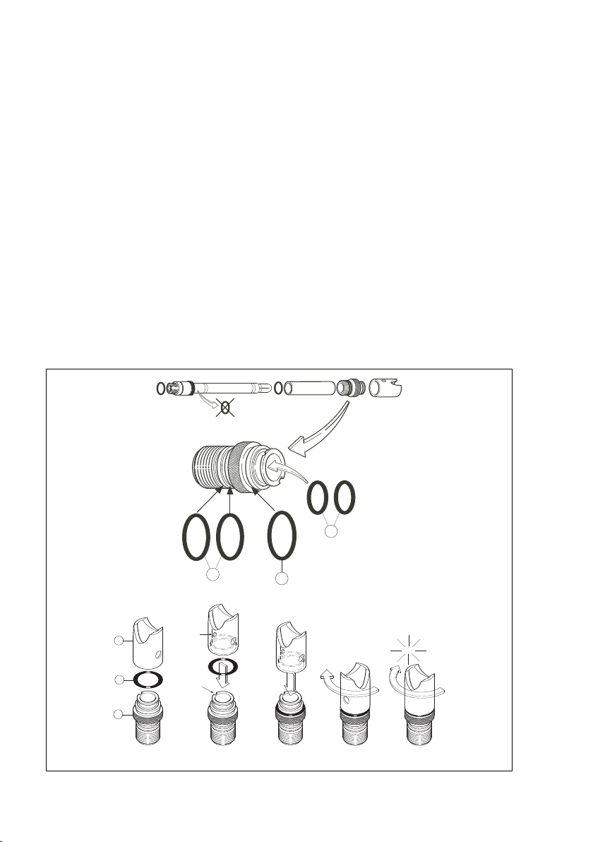
3-3. Preparing the electrode
1.
Romove the “wet” pocket.
Squeeze it to let in air
Remark:
The electrode used with the
retractable fitting if supplied
separately or as an option with
the fitting. The electrode is ready
for immediate use because it is
shipped in a 'wet' pocket.
2.
Remove the two O-rings (not
used). These O-rings are supplied with the electrode and NOT
used in the PR20 retractable fitting.
3.
Mount the separately delivered
O-ring on the connector plug.
Push the spacer and the O-ring
over the electrode. This is a plastic tube + O-ring delivered with
the PR20.
3-4. Mounting the electrode
1.
Push the cage onto the electrode
(see fig. 3-4.)
2.
Press the assembly into the
probe.
3.
Tighten it by turning clock-wise.
Note:
The cage fits firmly on the electrode, caused by the O-rings inside the cage. The assembly of
electrode and cage can be tightened until it stops. No tools are
necessary.
IMPORTANT NOTICES
Before the electrode is inserted into
the process, the electrode needs to
be cleaned and calibrated. The calibration procedure is normally
described in the instruction manual
of the pH transmitter. Before the
cage is pushed onto the electrode,
the stopper should be removed
(see Nr. 30 in the exploded view).
IM 12B6K3-E-E
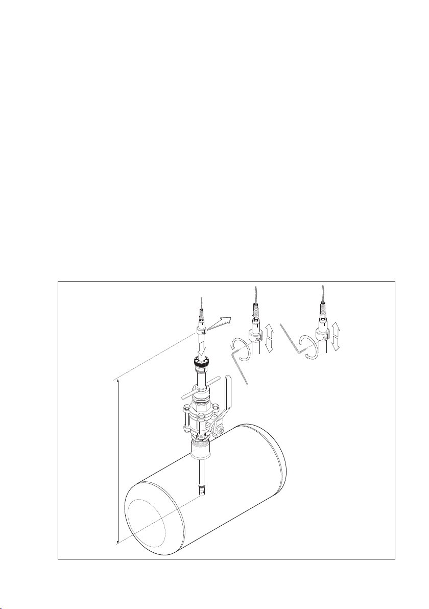
Page 13

11
Unscrew
the pigtail.
One will
hear clicking.
Move the
pigtail
Move the
plug-in
connector
Move
the cable
Turn thight
Press
figure 3.3 preparing the
electode for use
figure 3.4 Mounting the electrode in the PR20
fitting
IM 12B6K3-E-E
Page 14

12
FIXING SCREW
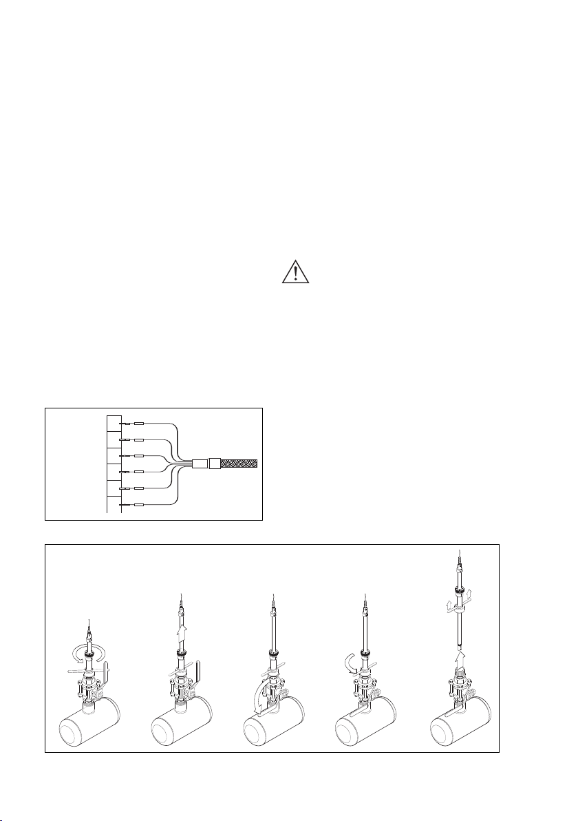
3-5. Probe insertion
Insert the probe according to next
procedure (see also fig. 3-5):
1.
Position the probe for insertion.
2.
Turn the T-bar key clockwise
3.
Open the ball-valve.
4.
Push the probe into the process.
5.
Fix the probe by turning the
fixing screw clockwise.
Remarks:
1.
Turning the T-bar key can
ONLY be done when the valve is
closed. Make sure the probe is
firmly fixed.
1
2.
Pushing the probe into the process needs a force to overcome
the pressure of the system and
the friction of the damping rings
in the fitting.
3. The locking mechanism can be
turned until the probe is firmly
fixed at the measuring position.
4. The memory ring can be fixed at
the actual insertion position. See
§3-6 on adjusting the insertion
depth.
4
Fig. 3-5. Probe insertion
IM 12B6K3-E-E
2
5
3
Page 15
13
3-6. Adjusting the insertion
depth
The insertion depth of the electrode
can be adjusted to your preference
(see fig. 3-6). An insertion depth of
at least 0.2 m is recommended for
a fast response of the temperature
sensor. This sensor is located
above the combined electrode.
When the probe is inserted for 0.2
m or more the temperature sensor
will follow the process temperature
accurate.
The 'memory'ring can be positioned at the actual insertion position
of the probe. The "Allan"key, supplied with the fitting is used to fix
the 'memory'ring at the desired
position. The maximum insertion
depth is related to the probe length
mentioned in the model code of the
fitting.
3-7. Wiring
The cable used in the PR20
retractable fitting is prepared for
easy connection to pH transmitters.
The numbering of the wires is
accordingly to the standard numbering of Yokogawa transmitters.
Remark:
To make full use of the capabilities
of the combined pH/Reference
electrode, the cooperation with
Yokogawa pH transmitters is
preferred.
fig. 3-6 variable insertion depht
IM 12B6K3-E-E
Page 16
14
Temperature 11
Temperature 12
Reference 13
Liquid Earth 14
Glass electrode 15
Shield 16
Transparent
Yellow
Red
Black
Black
Blue
4. MAINTENANCE
4-1. General
Before the combined electrode can
be serviced, the probe with the
electrode should be physically
separated from the process. The
PR20 retractable fitting can be
retracted from the measuring position in the maintenance position by
following the procedure described
in §4-2.
When (optional) flush ports are available, it is not necessary to disassemble the probe as indicated in
items [4] and [5] of fig. 4-2. The
flush ports enable you to clean
and/or calibrate the electrode in the
position shown in [3] of fig. 4-2.
For replacement of the electrode
the probe has to be disassembled.
Fig. 4.1. Cable markers
4-2. Cleaning
Retract the probe from the process
for cleaning the electrode (see also
fig. 4-2):
1.
Release the fixing screw.
2.
Pull out the probe.
3.
Close the ball-valve (*).
4.
Unlock the probe.
5.
Take out the probe.
* If flush ports are available the sensor can be flushed with cleaning
liquid.
ATTENTION:
1. Stand clear when releasing
the fixing screw! Due to the
process pressure the probe
can be pressed out.
2. The T-bar can only be operated when the ball-valve is closed. Make sure it is closed
completely.
3. The friction of the O-rings will
slow down the probe when it is
retracted.
4. When the sensitivity of the electrode has decreased or the
response has slowed down, the
electrode should be cleaned.
12345
Fig. 4.2. Exsertion of the probe
IM 12B6K3-E-E
Page 17

15
If cleaning with hot water is not
water is not sufficient, more aggressive water based agents should be
used.
- Deposits of limes, hydroxides or
carbonates can be removed by
immersing the electrode in a solution containing diluted hydrochloric acid. Afterwards rinse the electrode with water.
- Deposits of oil and fat can be
removed with hot water in conjunction with a detergent. When
the results are unsatisfactory a
mild (carbonate based) abrasive
can be used.
- Protein (albuminous) deposits
should be removed with a protein
enzymatic solution. For instance a
solution containing 8.5 ml concentrated hydrochloric acid and
10 gr pepsin in 1 litre water.
ATTENTION
Avoid using non-polar solvents like
tri-chloro ethylene, toluene or hexane. Even cleaning with ethanol or
acetone is not recommended.
These solvents will break up the
gel-layer on the glass bulb and
afterwards needs to remain soaked
in water for at least 12 hours before
functioning normal.
The PTFE diaphragm of the combined electrode can sometimes be
regenerated by putting it in hot (60
to 80°C) 1 molar Potassium chloride (KCl) solution and letting it cool
to room temperature.
After cleaning the probe is re-inser
ted into the process by following
the reverse procedure (see §3-5).
4-3. Calibration
It is recommended to start calibration with a clean electrode. Always
calibrate a new electrode.
With the electrode connected to the
transmitter a calibration can take
place. Check the appropriate chapters in the instruction manual of the
pH transmitter for details.
To take out the probe for cleaning
the electrode, follow the procedure
described in §4-2.
General procedure for calibration
To calibrate a pH transmitter two
buffer solutions with known pH
value are required. It is recommended that one buffer solution has a
value near pH 7.
Depending on the liquid to be
measured the second buffer solution should either be in the acidic or
base area. Normally the buffers pH
4.01 or 9.22 are used.
Generally the procedure for calibration is as follows:
- Clean the electrode
- Rinse the electrode with water
- Immerse the electrode in the first
buffer solution (pH 7)
- Adjust the asymmetry setting of
the transmitter for reading a
known value
- Rinse the electrode with water
- Immerse the electrode in the
second buffer (pH 4 or pH 9)
- Adjust the slope setting of the
-
transmitter for reading a known
value
- Rinse the electrode with water.
IM 12B6K3-E-E
Page 18
16
1
2
3
click
123
4
180º
pin
slot
27
26
28
During calibration the temperature
compensation should be active. It is
advised to, calibrate with buffer
solutions at a temperature near the
process temperature.
After calibration the probe with
electrode is replaced following the
procedure in §3-5.
4-4. Replacing the electrode
Start with removing the probe by
following the procedure described
in §4-2.
1
Turn the cage anti-clockwise
2
Pull out the assembly.
3
Take off the cage, spacer
and O-ring.
Now the electrode can be exchanged for a new one. See §3-3 for
preparation of the new electrode.
4-5. Replacing the O-rings
The drawing (see fig. 4-3) shows
the position of the sealing O-rings
on the outside and the inside of the
cage. Exchange them when renewing the electrode.
The O-rings are available as spare
parts. Refer to the exploded view
for the numbers.
The protection cage can be split
into two parts. The threaded part
[24] contains five O-rings. Three
O-rings on the outside [26 and 27]
Fig. 4-3. Replacing the O-rings
IM 12B6K3-E-E
Page 19

17
can be replaced by new ones easily.
Two O-rings [28] are located inside
the protection cage and need to be
taken out, using a pointed tweezers
or needle. This will damage the
material, so the rings cannot be
used again.
Put in new O-rings without using
mechanical tools, preferably with
your fingers. Fold the O-ring before
inserting it into the cage. It will pop
into place easily.
The single O-ring [14] at the connector is delivered with the fitting
and seals the plug for moisture.
Replace it when it is damaged or
when you think it is necessary.
4-6. Replacing the cable
Follow the procedures for retraction
and disassembling from the previous chapters (see §4-1 to 4-5).
After removing the electrode the
cable can be removed by disassembling the cable gland [2] as
indicated in the exploded view in
chapter 5.
Then the cable [1] can be removed
and a new one can be inserted.
Reassemble the cable gland onto
the cable and tighten it.
4-7. Flush port connections
The PR20 retractable fitting can be
equipped with (optional) flush ports
on the flanged adapters. This enables you to flush the electrode with
water or cleaning agent when the
probe is in the fully retracted position (see fig. 4-4).
There are four (4) flush ports available. They can be used according to
your preferences. The flush ports
are tapered 1/8" NPT-female for
small diameter connectors.
It is also possible to make buffer
solution flow through and calibrate
the combined electrode without
dismounting the probe.
Fig. 4-4. Flush ports
IM 12B6K3-E-E
Page 20
18
IM 12B6K3-E-E
Page 21

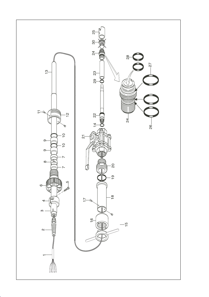
5. EXPLODED VIEW
1 Cable with plug-in connector
2 Cable gland
3 Outer tube
4 Positioning ring
5 "Allan" screw
6 Main fixing screw
7 Squeezing ring (2pcs)
8 Clamping ring
9 Bushing (2pcs)
10 O-rings (2pcs), Viton 70° shore (20.2x3.5)
11 Fixing screws (2 pcs)
12 Protection ring
13 Inner tube
14 O-ring Viton 70° shore (12x1)
15 T-bar with key
16 Nut
17 Fixing screws (2 pcs)
18 Chamber
19 O-ring Viton 70° shore (29.7 x 3.5)
20 Adapter (optional)
21 Ball-valve (optional)
22 Combined pH/reference electrode
23 Spacer
24 Electrode holder
25 Protection sleeve
26 O-rings (2 pcs), Viton 70° shore (15.6 x 1.78)
27 O-ring, Viton 70° shore (17.12 x 2.62)
28 O-rings (2 pcs), Viton 70° shore (11 x 3)
29 O-ring EPDM 70° shore (11.92 x 2.62)
30 Stopper (remove)
19
IM 12B6K3-E-E
Page 22

20
6. SPARE PARTS LIST
K1520AX O-ring set 1 26, 27, 28, 14
K1520AY O-ring set 2 10, 19
K1520KA Holder set (AISI 316) 24, 25, 26, 27, 28
K1520KE Holder set (titanium) 24, 25, 26, 27, 28
K1520AW Gland set 2
K1520LP Cable 5 m (Pt100) 1
K1520LQ Cable 5 m (Pt1000) 1
K1520LS Cable 10 m (Pt100) 1
K1520LT Cable 10 m (Pt1000) 1
K1520AZ Spacer 23
K1520KD Clamp ring 8
K1520KC Fixing screw 6
K1520KF Positioning ring 4, 5
K1520TA Clamping set 7, 8, 9
K1520TF Nut 16
K1520TK Key 15
K1520TN Outer tube 3
K1520UB Clamping set (Titanium) 7, 8, 9
K1520UH Outer tube 1.0 m (SS) 3
K1520UF Outer tube 0.5 m (Ti) 3
K1520UJ Outer tube 1.0 m (Ti) 3
IM 12B6K3-E-E
Page 23

21
IM 12B6K3-E-E
Page 24

YOKOGAWA HEADQUARTERS
9-32, Nakacho 2-chome,
Musashinoshi
Tokyo 180
Japan
Tel. (81)-422-52-5535
Fax (81)-422-55-1202
E-mail: webinfo@mls.yokogawa.co.jp
www.yokogawa.co.jp
YOKOGAWA CORPORATION OF AMERICA
2 Dart Road
Newnan GA 30265
United States
Tel. (1)-770-253-7000
Fax (1)-770-251-2088
E-mail: info@yca.com
www.yokogawa.com/us
Yokogawa has an
extensive sales and
distribution network.
Please refer to one of our
web-sites to contact your
nearest representative.
YOKOGAWA EUROPE B.V.
Databankweg 20
3821 AL AMERSFOORT
The Netherlands
Tel. +31-33-4641 611
Fax +31-33-4641 610
E-mail: info@nl.yokogawa.com
www.yokogawa.com/eu
YOKOGAWA ELECTRIC ASIA Pte. Ltd.
5 Bedok South Road
Singapore 469270
Singapore
Tel. (65)-241-9933
Fax (65)-241-2606
E-mail: webinfo@yas.com.sg
www.yokogawa.com.sg
IM 12B6K3-E-E 09-510 (A) Q
Subject to change without notice
Copyright
©
Printed in The Netherlands
 Loading...