

Page 1
Instruction
YOKOGAWA
Manual
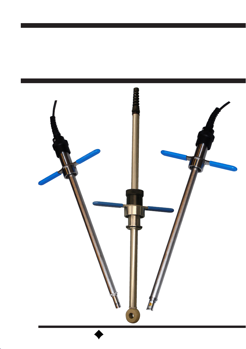
Model PR10
Manual Retractable Fitting
IM 12B6K3-01E-E
4th edition
Page 2

2
(BG)
Всички улътвания за продукти от серията
ATEX Ex ce лредлагат на английски
език. Ако се нуждаете oт улътвания за
продукти oт серията Ex на родния ви
eзик, ce свържете c най-близкия oфис или
представителство на фирма Yokogawa.
(CZ)
Všechny uživatelské příručky pro výrobky, na
něž se vztahuje nevýbušné schváleni ATEX
Ex, jsou dostupné v angličtině. Požadujete-li
pokyny týkající se výrobků s nevýbušným
schválením ve vašem lokálním jazyku,
kontaktujte prosím vaši nejbližší reprezentačni
kancelář Yokogawa.
(E)
Todos los manuales de instrucciones para
los productos antiexplosivos de ATEX están
disponibles en inglés. Si desea solicitar las
instrucciones de estos artículos antiexplosivos
en su idioma local, deberá ponerse en contacto
con la oficina o el representante de Yokogawa
más cercano.
(F)
Tous les manuels d’instruction des produits
ATEX Ex sont disponibles en langue anglaise.
Si vous nécessitez des instructions relatives
aux produits Ex dans votre langue, veuillez
bien contacter votre représentant Yokogawa le
plus proche.
(D)
Alle Betriebsanleitungen für ATEX Ex
bezogene Produkte stehen in den Sprachen
Englisch. Sollten Sie die Betriebs- anleitungen
für Ex-Produkte in Ihrer Landessprache
benötigen, setzen Sie sich bitte mit Ihrem
örtlichem Yokogawa-Vertreter in Verbindung.
(DK)
Alle brugervejledninger for produkter relateret
til CE er tilgængelige på engelsk. Skulle De
ønske yderligere oplysninger om håndtering
af CE produkter på eget sprog, kan De
rette henvendelse herom til den nærmeste
Yokogawa afdeling eller forhandler.
(EST)
Kõik ATEX Ex toodete kasutamisjuhendid on
esitatud inglise keeles. Ex seadmete muukeelse
dokumentatsiooni saamiseks pöörduge lähima
lokagava (Yokogawa) kontori või esindaja
poole.
(GB)
All instruction manuals for ATEX Ex related
products are available in English. Should you
require Ex related instructions in your local
language, you are to contact your nearest
Yokogawa office or representative.
(GR)
Ολα τα εγχειριδια λειτουργιας των
προιοντων με ATEX Ex διατιθενται στα
Αγγλικα. Σε περιπτωση πον χρειαζεοτε
οδηγιεξ σχετικα με Ex στην τοπικη
γλωσσα παρακαλονμε επικοινωνηστε με
το πλησιεστερο γραφειο τηζ Yokogawa η
αντιπροσωπο τηξ.
(H)
Az ATEX Ex mûszerek gépkönyveit angol
nyelven adjuk ki. Amennyiben helyi nyelven
kérik az Ex eszközök leírásait, kérjük keressék
fel a legközelebbi Yokogawa irodát, vagy
képviseletet.
(I)
Tutti i manuali operativi di prodotti ATEX
contrassegnati con Ex sono disponibili in
inglese. Se si desidera ricevere i manuali
operativi di prodotti Ex in lingua locale,
mettersi in contatto con l’ufficio Yokogawa
più vicino o con un rappresentante.
IM 12B6K3-01E-E
Page 3

(LV)
Visas ATEX Ex kategorijas izstrâdâjumu
Lietoðanas instrukcijas tiek piegâdâtas
angïu valodâs. Ja vçlaties saòemt Ex ierîèu
dokumentâciju citâ valodâ, Jums ir jâsazinâs
ar firmas Jokogava (Yokogawa) tuvâko ofisu
vai pârstâvi.
(LT)
Visos gaminiø ATEX Ex kategorijos
Eksploatavimo instrukcijos teikiami anglø
kalbomis. Norëdami gauti priestaisø Ex
dokumentacijà kitomis kalbomis susisiekite su
artimiausiu bendrovës Yokogawa biuru arba
atstovu.
3
(PL)
Wszystkie instrukcje obsługi dla urządzeń
w wykonaniu przeciwwybuchowym Ex,
zgodnych z wymaganiami ATEX, dostępne
są w języku angielskim. Jeżeli wymagana
jest instrukcja obsługi w Państwa lokalnym ję
zyku, prosimy o kontakt z najbliższym biurem
Yokogawy.
(RO)
Toate manualele de instructiuni pentru
produsele ATEX Ex sunt in limba engleza.
In cazul in care doriti instructiunile in limba
locala, trebuie sa contactati cel mai apropiat
birou sau reprezentant Yokogawa.
(M)
Il-manwali kollha ta’ l-istruzzjonijiet għal
prodotti marbuta ma’ ATEX Ex huma
disponibbli bl-Ingliż. Jekk tkun teħtieģ
struzzjonijiet marbuta ma’ Ex fil-lingwa
lokali tiegħek, għandek tikkuntattja lill-eqreb
rappreżentan jew uffiććju ta’ Yokogawa.
(NL)
Alle handleidingen voor producten die te
maken hebben met ATEX explosiebeveiliging
(Ex) zijn verkrijgbaar in het Engels. Neem,
indien u aanwijzingen op het gebied van
explosiebeveiliging nodig hebt in uw eigen
taal, contact op met de dichtstbijzijnde
vestiging van Yokogawa of met een
vertegenwoordiger.
(P)
Todos os manuals de instruções referentes
aos produtos Ex da ATEX estão disponíveis
em Inglês. Se necessitar de instruções na
sua língua relacionadas com produtos Ex,
deverá entrar em contacto com a delegação
mais próxima ou com um representante da
Yokogawa.
(S)
Alla instruktionsböcker för ATEX Ex
(explosionssäkra) produkter är tillgängliga
på engelska. Om Ni behöver instruktioner
för dessa explosionssäkra produkter på
annat språk, skall Ni kontakta närmaste
Yokogawakontor eller representant.
(SF)
Kaikkien ATEX Ex-tyyppisten tuotteiden
käyttöhjeet ovat saatavilla englannin-. Mikäli
tarvitsette Ex-tyyppisten tuotteiden ohjeita
omalla paikallisella kielellännne, ottakaa
yhteyttä lähimpään Yokogawa-toimistoon tai
-edustajaan.
(SK)
Všetky návody na obsluhu pre prístroje s
ATEX Ex sú k dispozícii v jazyku anglickom.
V prípade potreby návodu pre Ex-prístroje vo
Vašom národnom jazyku, skontaktujte prosím
miestnu kanceláriu firmy Yokogawa.
(SLO)
Vsi predpisi in navodila za AEX Ex sorodni
pridelki so pri roki v anglišèini. Èe so Ex
sorodna navodila potrebna v vašem tukejnjem
jeziku, kontaktirajte vaš najbliši Yokogawa
office ili predstaunika.
IM 12B6K3-01E-E
Page 4

4
Contents
1. INTRODUCTION 5
1.1 Description 5
1.2 Features 5
1.3 Warranty 5
2. SPECIFICATIONS 5
2.1 General 5
2.2 Model- and Suffix Codes 6
3. INSTALLATION 7
3.1 Unpacking and checking 7
3.2 Installation site 7
3.3 Safety precautions 7
3.4 Installation method 7
3.5 Assembly of accessories 7
3.6 Dimensions 8
3.6.1 Dimensional drawing PR10...-D32 with mounted pH sensor 8
3.6.2 Dimensional drawing PR10...-D32 with mounted SC4A sensor 9
3.6.3 Dimensional drawing PR10...-D50 with mounted SC4A sensor 10
3.6.4 Dimensional drawing PR10...-D50 with mounted ISC40 sensor 11
3.7 Options PR10 12
3.8 Sensor mounting 14
3.8.1 Mounting a 12mm sensor 14
3.8.2 Mounting a 12mm PG13.5 sensor in pH13 14
3.8.3 Mounting the SC4A 15
3.8.4 Mounting the ISC40 15
4. MAINTENANCE 17
4.1 General 17
4.2 Probe insertion 17
4.3 Taking out the sensor 17
4.4 Replacing the sensor 17
4.5 Replacing the sealings 17
4.6 Drain ports connection 17
5. EXPLODED VIEW 18
6 SPAREPARTS 20
IM 12B6K3-01E-E
Page 5
1. INTRODUCTION
5
2. SPECIFICATIONS
1.1 Description
The retractable fitting with ball valve allows
a safe insertion and retraction of a sensor
while the process is under pressure. It
can be mounted in a variety of positions.
The insertion depth can be selected on
site. An insertion stop is provided to set
the position of the sensor in the process.
The mechanism for releasing the probe
is designed to operate only when the ball
valve is closed, thus ensuring an effective
safety precaution and avoiding production
loss. The sensor can be replaced or
calibrated easily.
1.2 Features
• One model for pH, conductivity
and inductive conductivity sensors
• Integrated protection cage
• Build-in scraper to avoid contamination
of the fitting
• Usable for wide range of sensors
• A safe “through the valve” insertion
and retraction design
• Simplified installation by optional
ball valves with flanged or tapered
connections
• Optional flush port for keeping moist,
cleaning and calibration
• Available in Stainless Steel and with
Titanium shaft cage and adapters for
more harsh applications
1.3 Warranty
Yokogawa warrants that the goods
delivered are made from new materials to
the best workmanship available. Malfunction
of any of the delivered goods or parts of
it, can only lead to replacement of the
damaged parts. No claims can be made
to damages or accidents resulting from the
use of the goods. No claims can be made
to the expected or promised performance
of the goods under any circumstances.
Damaged goods or parts should be sent to
the local service organization for warranty
claim purposes. Yokogawa has the right to
deny warranty claims after investigation of
the data and materials.
2.1 General
A. Wetted materials
- For sensor check Instruction Manual
- Stainless steel AISI 316L / Titanium
- O-ring seals: Viton 70° shore
B. Non-wetted materials
- For sensor check Instruction Manual
- Stainless steel AISI 316, 304
- Polypropylene glass filled
C. Insertion length
- Ref. mechanical drawing Fig. 2 - 5
on page 6 - 9.
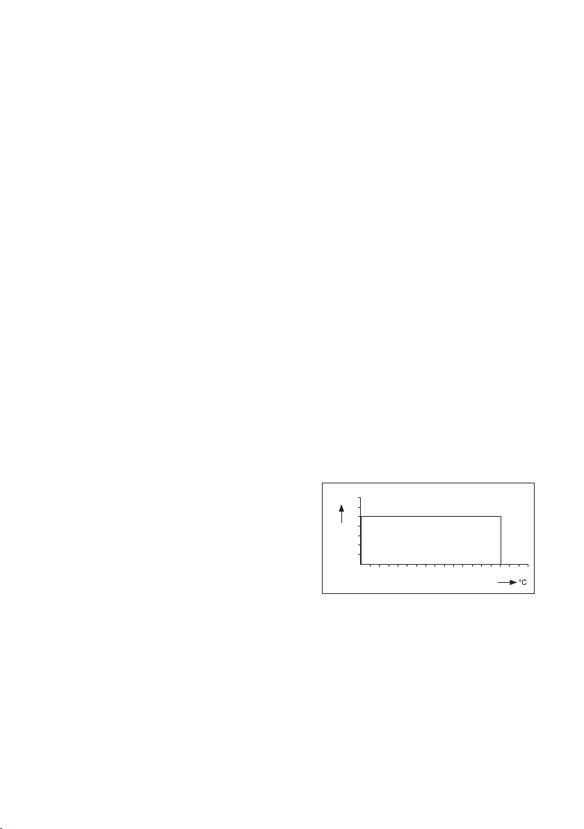
D. Pressure/temperature ratings
- Static conditions: see Fig. 1.
- Operating conditions during
extraction and insertion max.
500kPa, max. 100°C
E. Flange ratings:
- DIN flange DN32 PN10
- ANSI flange 1¼“ 150 lbs
- DIN flange DN50 PN10
- ANSI flange 2“ 150 lbs
F. Specifications of the sensor used
- Please check sensor specifications
G. Weight
- Approx 2.5 kg excl. ball valve
bar
12
10
8
6
4
2
0 10 20 30 40 50 60 70 80 100 120 140 160
FIG. 1 Pressure / Temperature graphic
AISI 316
IM 12B6K3-01E-E
Page 6

6
2.2 Model- and Suffix Codes
Model Suffix Options Description
PR10 Retractable fitting general purpose
Material fitting -S Stainless steel
-T Titanium (tube and sensor holder only)
Material O-rings -V Viton
Tube length -L5 Tube length 0.5 meter
Connection -D32 DN32 / 1¼”
-D50 DN50 / 2”
Measuring sensor -PH12 For 12mm pH sensors Y-cap
-PH13 For 12mm pH sensors PG13.5 cap
-SC4A For SC4A
-ISC4 For ISC40
-NNNN No parameter specification
Adapter screw-in /SA125 ISO 228/1 G1¼ to 1¼” M-NPT
/SA200 ISO 228/1 G2 to 2” M-NPT
Flange adapter /FA125 Flange adapter drain 1¼” 150 Lbs
/FN125 Flange adapter no drain 1¼” 150 Lbs
/FA200 Flange adapter drain 2” 150 Lbs
/FN200 Flange adapter no drain 2” 150 Lbs
/FAD32 Flange adapter drain DN32 PN10
/FND32 Flange adapter no drain DN32 PN10
/FAD50 Flange adapter drain DN50 PN10
/FND50 Flange adapter no drain DN50 PN10
Adapter weld-in /WA125 Straight weld-in adapter ISO 228/1 G1¼
/WA200 Straight weld-in adapter ISO 228/1 G2
Ball-valves /BF125 Ball-valve flanged 1¼” 150 Lbs*
/BF200 Ball-valve flanged 2” 150 Lbs*
/BFD32 Ball-valve flanged DN32 PN10*
/BFD50 Ball-valve flanged DN50 PN10*
/BS125 Ball-valve screw-in 1¼” F-NPT*
/BS200 Ball-valve screw-in 2” F-NPT*
Certificates /M Material certificate 3.1 according to EN-10-
024 (DIN50-049) (on wetted parts).
*With Ball-valves flange adapters or screw-in adapters are necessary.
IM 12B6K3-01E-E
Page 7

3. INSTALLATION
7
3.1 Unpacking and checking
When you receive the PR10 retractable
fitting it is packed in a cardboard box. Open
the box and check that the model code on
the fitting is the same as the one on the
packing list. Refer to paragraph 2.2 for the
model code. Also check that it is supplied
with the options you ordered. The options
can be delivered in separate boxes. If you
have any problems or questions, contact
your nearest Yokogawa service centre or
sales organization for support. The PR10
retractable fitting has an identification plate
on the protection ring with the full model
code and a serial number.
3.2 Installation site
The PR10 fitting is intended to be used for
in-line measurement. When it is delivered
with an optional ball valve or when it is used
in combination with a locally purchased
ball valve, the process does not need
to be interrupted for maintenance of the
sensor. Mounting location can be in a large
diameter pipeline or a vessel.
3.3 Safety precautions
The PR10 fitting is designed for maximum
safety in operation. For optimum safety
a flanged ball valve is recommended.
Yokogawa does not accept any claims
or penalties on possible damages or
accidents that occur in operation of the
PR10 fitting. The installation of the probe
is to be implemented under the local
safety regulations for pressurized vessels
or pipelines for retraction or insertion. The
instructions given in this manual must be
followed exactly.
3.4 Installation method
It is important to have the point of
measurement in a location that is truly
representing the process composition.
Check whether the specifications of the
sensor fulfill the maximum occurring
process conditions. The fitting has several
optional connection possibilities. Check
that you received the correct size and
type. Install the fitting in a convenient
location for maintenance and calibration.
For maintenance or calibration the probe
will need a space of about 2m for total
retraction (depending on probe length
and optional adapters and/or ball valves).
Installation in a bend of a pipe line is a good
measurement position. When inserting the
PR10 retractable fitting in a perpendicular
position to the process flow, the flow
velocity will put a mechanical force on the
probe. Take care that this force is not too
large. It is recommended to have the PR10
retractable fitting positioned at a 90° angle
into the process stream.
Note: Do not insert the fitting into the
process without the sensor mounted!
The sensor is delivered separately in
a box. Start with the assembly of the
sensor into the probe and follow the
instructions for the preparation of a
new sensor. Refer to paragraph 3.8.
3.5 Assembly of accessories
Optional accessories are (often) delivered in
separate boxes. When an optional ball valve
is ordered, it should be mounted to the
measuring position first. When the ball valve
is in place, the process line is secure.
IM 12B6K3-01E-E
Page 8

8
Dimensional drawing PR10...-D32 with
mounted pH sensor
3.6 Dimensions
3.6.1 Dimensional drawing PR10...-D32 with mounted pH sensor
unit mm (inches)
381 (15")
110
PR10-..-..-....-D32.-PH...../SA125/BS125
414 (16.3")
54
PR10-..-..-....-D32-PH...../F..125/BF125
PR10-..-..-....-D32-PH...../F..D32/BFD32
520 (20.5")
PR10- .. -V-L5-D32-PH12
PR10- .. -V-L5-D32-PH13
FIG. 2 Dimensional drawing PR10...-D32 with mounted pH sensor
IM 12B6K3-01E-E
Page 9

Dimensional drawing PR10...-D32 with
mounted SC4A sensor
3.6.2 Dimensional drawing PR10...-D32 with mounted SC4A sensor
unit mm (inches)
390 (15.35")
9
110 (4.35”)
PR10-..-..-....-D32-SC4A/SA125/BS125
54 (2.15”)
PR10-..-..-....-D32-SC4A/F..125/BF125
PR10-..-..-....-D32-SC4A/F..D32/BFD32
779 (30.7")
PR10- .. -V-L5-D32-SC4A
423 (16.7")
529 (20.8")
FIG. 3 Dimensional drawing PR10...-D32 with mounted SC4A sensor
IM 12B6K3-01E-E
Page 10

10
3.6.3 Dimensional drawing PR10...-D50 with mounted SC4A sensor
unit mm (inches)
362 (14.25")
PR10-..-..-....-D50-SC4A/SA200/BS200
142 (5.6”)
390 (15.4")
PR10-..-..-....-D50-SC4A/F..200/BF200
82 (3.25”)
PR10-..-..-....-D50-SC4A/F..D50/BFD50
779 (30.7")
529 (20.8")
PR10- .. -V-L5-D50-SC4A
FIG. 4 Dimensional drawing PR10...-D50 with mounted SC4A sensor
IM 12B6K3-01E-E
Page 11

11
3.6.4 Dimensional drawing PR10...-D50 with mounted ISC40 sensor
unit mm (inches)
366 (14.4")
PR10-..-..-....-D50-ISC4/SA200/BS200
142 (5.6”)
394 (15.5")
PR10-..-..-....-D50-ISC4/F..200/BF200
82 (3.25”)
PR10-..-..-....-D50-ISC4/F..D50/BFD50
783 (30.8")
533 (21")
PR10- .. -V-L5-D50-ISC4
FIG. 5 Dimensional drawing PR10...-D50 with mounted ISC40 sensor
IM 12B6K3-01E-E
Page 12

12
C
D
A
L
C
A
L
E
D
A
C
A
L
B
E
D
L
A B
C
D
A
L
C
A
L
B
A
L
E
A B
C
D
F
G
A
L
B
A
B
L
C
A
L
B
Bb
L
Di
L
C
D
A
A
E
A B
C
D
F
G
A
L
B
A
B
L
C
A
L
B
A
L
B
3.7 Options PR10
A
L
B
C
FIG. 6 Dimensions of the PR10 options
Table 1 Dimensions options in mm (inches)
Option Description Fig. A B L C Bb D E Di Dg K
/SA125 ISO 228/1 G1¼ to 1¼” M-NPT A ISO 228/1 - G1¼ 1¼” NPT 60 (2.4)
/SA200 ISO 228/1 G2 to 2” M-NPT A ISO 228/1 - G2 2” NPT 58 (2.3)
/FA125 Flange adapter drain 1¼” 150 Lbs D , G ISO 228/1 - G1¼ 69.5 (2.7) 66 (2.6) 29 (1.1) 15.7 (0.6) 117.3 (4.6) 1/8” NPT 47 (1.9) 15.7 (0.6) 88.9 (3.5)
/FN125 Flange adapter no drain 1¼” 150 Lbs C , G ISO 228/1 - G1¼ 69.5 (2.7) 66 (2.6) 29 (1.1) 15.7 (0.6) 117.3 (4.6) 47 (1.9) 15.7 (0.6) 88.9 (3.5)
/FA200 Flange adapter drain 2” 150 Lbs D , G ISO 228/1 - G2 101 (4) 77 (3) 32 (1.3) 25 (1) 165 (6.5) 1/8” NPT 73 (2.9) 19 (0.7) 120-125 (4.7)-(4.9)
/FN200 Flange adapter no drain 2” 150 Lbs C , G ISO 228/1 - G2 101 (4) 54 (2.1) 32 (1.3) 25 (1) 165 (6.5) 73 (2.9) 19 (0.7) 120-125 (4.7)-(4.9)
/FAD32 Flange adapter drain DN32 PN10 D , G ISO 228/1 - G1¼ 69.5 (2.7) 66 (2.6) 29 (1.1) 16 (0.6) 140 (5.5) 1/8” NPT 47 (1.9) 18 (0.7) 100 (3.9)
/FND32 Flange adapter no drain DN32 PN10 C , G ISO 228/1 - G1¼ 69.5 (2.7) 66 (2.6) 29 (1.1) 16 (0.6) 140 (5.5) 47 (1.9) 18 (0.7) 100 (3.9)
/FAD50 Flange adapter drain DN50 PN10 D , G ISO 228/1 - G2 101 (4) 77 (3) 32 (1.3) 25 (1) 165 (6.5) 1/8” NPT 73 (2.9) 19 (0.7) 120-125 (4.7)-(4.9)
/FND50 Flange adapter no drain DN50 PN10 C , G ISO 228/1 - G2 101 (4) 54 (2.1) 32 (1.3) 25 (1) 165 (6.5) 73 (2.9) 19 (0.7) 120-125 (4.7)-(4.9)
/WA125 Straight weld-in adapter ISO 228/1 G1¼ B ISO 228/1 - G1¼ 42 (1.7) 45 (1.8)
/WA200 Straight weld-in adapter ISO 228/1 G2 B ISO 228/1 - G2 49 (1.9) 45 (1.8)
/BF125 Ball-valve flanged 1¼” 150 Lbs F 54 (2.1) 118 (4.6) 32 (1.3) M14 89 (3.5)
/BF200 Ball-valve flanged 2” 150 Lbs F 82 (3.2) 150 (5.9) 50 (2) M16 121 (4.8)
/BFD32 Ball-valve flanged DN32 PN10 F 54 (2.1) 140 (5.5) 32 (1.3) M16 100 (3.9)
/BFD50 Ball-valve flanged DN50 PN10 F 82 (3.2) 165 (6.5) 50 (2) M16 125 (4.9)
/BS125 Ball-valve screw-in 1¼” F-NPT E 1¼” NPT 110 (4.3) 32 (1.3)
/BS200 Ball-valve screw-in 2” F-NPT E 2” NPT 142 (5.6) 50 (2 )
IM 12B6K3-01E-E
A
L
B
A
E
B
L
B
A
Di
L
Page 13

C
D
F
G
A
L
B
C
Dg
A
L
B
E
13
L
Di
K
D
Dg
Bb
Di
K
D
IM 12B6K3-01E-E
Page 14

14
3.8 Sensor mounting
3.8.1 Mounting a 12mm sensor
in pH12
1. Take the cable out of the box and cut off
the cable tie.
2. Tape the separate wires of the cable
together.
3. Take the fitting out of the box and
remove the sensor holder and Y-cap
adapter.
4. Slide the Y-cap adapter over the cable.
5. Release the pigtail (cable gland) com-
pletely. Do not undo the part in the metal
tube!
6. Lead the sensor cable through the tube
of the fitting, from the side where the
sensor holder has been removed.
7. Take the sensor out of the box.
8. Slide the O-ring (12x1) over the connec-
tor.
9. Connect the sensor to the cable.
10. Slide the sensor holder over the sensor.
11. Screw the Y-cap adapter onto the sensor
holder.
12. Hold the sensor still and turn the metal
tube onto the sensor holder. Don’t rotate
the sensor, but rotate the tube of the
fitting, because the cable can be disconnected from the sensor, when rotating it
13. Lead the loose part of the pigtail onto the
cable and screw it onto the fixed part.
14. Remove the tape.
3.8.2 Mounting a 12mm PG13.5
sensor in pH13
.
1. Take the cable out of the box and cut
off the cable tie
2. Tape the separate wires of the cable
together.
3. Take the fitting out of the box and
remove the sensor holder.
4. Release the pigtail (cable gland)
completely. Do not undo the part in the
metal tube!
5. Lead the sensor cable through the tube
of the fitting, from the side where the
sensor holder has been removed.
6. Take the sensor out of the box.
7. Screw the sensor in the sensor holder.
8. Connect the sensor to the cable.
9. Hold the sensor still and turn the metal
tube onto the sensor holder. Don’t
rotate the sensor, but rotate the tube
of the fitting, because the cable can be
disconnected from the sensor, when
rotating it
10. Lead the loose part of the pigtail onto
the cable and screw it onto the fixed
part.
11. Remove the tape.
Y CAP adapter
FIG. 7 Mounting pH sensor with pH12
FIG. 8 Mounting pH sensor with pH13
IM 12B6K3-01E-E
sensor holder
sensor holder
Page 15

15
3.8.3 Mounting the SC4A
1 Take the sensor out of the box and cut
off the cable tie
2 Bind the separate wires of the cable
together with a piece of tape.
3 Take the fitting out of the box and
remove the option(s), if necessary.
4 Release the pigtail (cable gland)
completely. Do not undo the part in the
metal tube!
5 Lead the sensor cable through the tube
of the fitting, from the side where the
knurled knob has been removed.
6 Hold the sensor still and turn the metal
tube onto the sensor. Don’t rotate the
cell, but rotate the tube of the fitting,
because the cable can be disconnected
from the cell, when rotating it
7 Lead the loose part of the pigtail onto
the cable and screw it onto the fixed
part.
8 Remove the tape.
3.8.4 Mounting the ISC40
1 Take the sensor out of the box and
remove the cable tie carefully
2 Bind the separate wires of the cable
together with a piece of tape
3 Take the fitting out of the box and
remove the option(s), if necessary
4 Release the pigtail (cable gland)
completely. Do not undo the part in the
metal tube!
5 Lead the sensor cable through the tube
of the fitting, from the side where the
knurled knob has been removed
6 Hold the sensor still and turn the metal
tube onto the sensor. Don’t rotate the
cell, but rotate the tube of the fitting,
because the cable can be disconnected
from the cell, when rotating it
7 Lead the loose part of the pigtail onto
the cable and screw it onto the fixed
part
8 Remove the tape
5
5
FIG. 10 Mounting the ISC40FIG. 9 Mounting the SC4A
IM 12B6K3-01E-E
Page 16

16
FIXING
SCREW
Remarks:
• Turning the T-bar key can only be done
when the valve is closed.
• Pushing the probe into the process needs
a force to overcome the pressure of the
system and the friction of the dampening
rings in the fitting.
• The locking mechanism can be tightened
until the probe is firmly fixed in the
measuring position.
• The insertion stop can be fixed in
the actual insertion position. Refer to
paragraph 4.5
for adjusting the insertion depth.
FIG. 11 Probe insertion
IM 12B6K3-01E-E
Page 17

4. MAINTENANCE
CAUTION
Retract/ insert at P < 5 Bar. Do not stand
behind immersion tube while retracting/
inserting
17
• The T-bar key can only be operated when
the ball valve is closed. Make sure it is closed
completely.
• The friction of the O-rings will slow down
the probe when it is retracted.
4.1 General
Before the sensor can be serviced, the probe
with the sensor inside should be physically separated from the process. The PR10
retractable fitting can be retracted from its
measuring position in the maintenance position by following the five step procedure mentioned in paragraph 4.2 in reverse order.
4.2 Probe insertion
1 Position the probe for insertion.
2 Turn the T-bar key clockwise.
3 Open the ball valve.
4 Push the probe into the process.
5 Fix the probe by turning the fixing screw
clockwise.
4.3 Taking out the sensor
Retract the probe from the process
according to the following procedure:
• Release the fixing screw.
• Pull out the probe.
• Close the ball valve (*).
• Turn the T-bar counter clockwise
• Take out the probe.
* If the option provides a drain port, the
process pressure can be relieved before
removing the sensor.
• Stand clear when releasing the fixing
screw! Due to the process pressure the
probe can be pressed out.
4.4 Replacing the sensor
Refer to paragraph 3.8
4.5 Replacing the sealings
For prevention of leakage due to aging
of the seals, the O-ring seals may need
replacement. Hereto, follow the procedure
below.
Procedure:
Remove the probe from the process. Follow
the procedure described in paragraph 4.2
Dismount the sensor. Follow the procedure
described in paragraph 3.8 in reverse order:
• Disassemble the housing of the insertion
tube.
• Replace the o-rings with the proper tools
(like K1525AF).
4.6 Drain ports connection
The PR10 retractable fitting can be
equipped with optional drain (or flush) ports
on the flanged adapter. The drain ports are
tapered 1/8” NPT female for small diameter
connectors.
Adjusting the insertion depth
The insertion depth of the sensor can be
adjusted to your preference. The insertion
stop can be set for the desired insertion
depth, using the key supplied with the fitting.
FIG. 12 Drain Port Connection FIG. 13 Flush Port Connection
IM 12B6K3-01E-E
Page 18

18
131415 161718
PR10- .. -V-L5-D32-....
13 25
27
161726
PR10- .. -V-L5 -D50-....
36 34
36 35
5. EXPLODED VIEW
2
1
3
31
37
36
5
6
4
7
33 43
8 9 10 / 10a
OR
PR10- .. -V-L5-D..-....
* Note: For sparepart numbers see Tabel 2
36
Spare part set
FIG. 14 Exploded view
PR10-S-V-L5-D32-PH12
PR10-S-V-L5-D32-PH13
PR10-S-V-L5-D32-SC4A
PR10-S-V-L5-D50-ISC4
PR10-S-V-L5-D50-SC4A
K1525AG Adapter Y-cap 30
K1525AB Sensor holder PG13.5 31
K1525AP Adapter SC4A - ISC40 32
K1525AA Outer tube 33
K1525BA O-ring set PR10-S-V-L5-D32 34
K1525BB O-ring set PR10-S-V-L5-D50 35
K1525BC Key set 36
K1525BD Squeezing set; 37
37
IM 12B6K3-01E-E
Page 19

36 34
131415 161718
PR10- .. -V-L5-D32-....
36 35
13 25
PR10- .. -V-L5 -D50-....
27
161726
34
303430
22 28 21/21a 20 19
OR
PR10- .. -V-L5-D32- PH13
PR10- .. -V-L5-D32- PH12
35
34
32
42
32
23
42
24/24a
PR10- .. -V-L5-D..- SC4A
PR10- .. -V-L5-D50- ISC4
31
35
34
32
42
30
34
41 41
31
19
34
30
PR10-T-V-L5-D32-PH12
PR10-T-V-L5-D32-PH13
PR10-T-V-L5-D32-SC4A
PR10-T-V-L5-D50-ISC4
PR10-T-V-L5-D50-SC4A
K1525AG Adapter Y-cap 30/40
K1525CB Sensor holder PG13.5 Titanium 41
K1525CP Adapter SC4A - ISC40 Titanium 42
K1525CA Outer tube Titanium 43
K1525BA O-ring set PR10-S-V-L5-D32 34
K1525BB O-ring set PR10-S-V-L5-D50 35
K1525BC Key set 36
K1525BD Squeezing set; 37
IM 12B6K3-01E-E
Page 20

6 Spareparts
Part no. Description
K1520LS Cable retractable fitting 10M PT100
K1520LT Cable retractable fitting 10M PT1000
K1525BZ Cable gland (5 pcs) 1
K1525AA Outer tube 33
K1525AB Sensor holder PG13.5 31
K1525AF O-ring pick up tool
K1525AG Adapter Y-cap 30
K1525BA O-ring set PR10-S-V-L5-D32 34
K1525BB O-ring set PR10-S-V-L5-D50 35
K1525BC Key set 36
K1525BD Squeezing set 37
K1525BE Set M16 bolt & washer (8 pcs)
K1525BF Set M14 bolt & washer (8 pcs)
K1525BG Gaskets ball valves - D50
K1525BH Gaskets ball valves - D32 + 1¼”
K1525BJ Gaskets ball valves - 2”
K1525BK Gaskets ball valves - 1¼”
K1525CA Outer tube titanium 43
K1525CB Sensor holder PG13.5 Titanium 41
K1525CP Sensor holder SC4a Titanium 42
K1525YA PR10/SA125
K1525YB PR10/FA125
K1525YC PR10/FN125
K1525YD PR10/FR200 - FAD50
K1525YE PR10/FN200 - FND50
K1525YF PR10/FAD32
K1525YG PR10/FND32
K1525YH PR10/WA125
K1525YJ PR10/WA200
K1525YK PR10/BF125
K1525YL PR10/BF200
K1525YM PR10/BFD32
K1525YN PR10/BF50
K1525YP PR10/BS125
K1541EM Adapter 2” NPT - G2SS
Table 2 Spare Parts
YOKOGAWA ELECTRIC CORPORATION
World Headquarters
9-32, Nakacho 2-chome, Musashino-shi
Tokyo 180-8750
Japan
www.yokogawa.com
YOKOGAWA CORPORATION OF AMERICA
2 Dart Road
Newnan GA 30265
USA
www.yokogawa.com/us
YOKOGAWA EUROPE BV
Euroweg 2
3825 HD AMERSFOORT
The Netherlands
www.yokogawa.com/eu
YOKOGAWA ELECTRIC ASIA Pte. LTD.
5 Bedok South Road
Singapore 469270
Singapore
www.yokogawa.com/sg
YOKOGAWA CHINA CO. LTD.
3F Tower D Cartelo Crocodile Building
No.568 West Tianshan Road Changing District
Shanghai, China
www.yokogawa.com/cn
YOKOGAWA MIDDLE EAST B.S.C.(c)
P.O. Box 10070, Manama
Building 577, Road 2516, Busaiteen 225
Muharraq, Bahrain
www.yokogawa.com/bh
Yokogawa has an extensive sales and
distribution network.
Please refer to the European website
(www.yokogawa.com/eu) to contact your
nearest representative.
IM 12B6K3-01E-E 04-1303 (A) I
Subject to change without notice Printed in The Netherlands
Copyright ®
 Loading...