

Page 1

User ’s
Manual
Chemical Cleaning
pH Measuring System
IM 12B07W01-04EN
IM 12B07W01-04EN
1st Edition
Page 2
u Introduction
n Chemical Cleaning pH Measuring System
Thank you for purchasing Chemical Cleaning pH Measuring System.
To have the system deliver its full capabilities, read this instruction manual thoroughly before you
use it. For safety reasons or to avoid possible damage to your equipment, strictly adhere to every
cautionary note that appears in this manual.
Chemical Cleaning pH Measuring System features automatic chemical cleaning of the pH sensor
without removing pH sensor, while maintaining its performance in pH measurement.
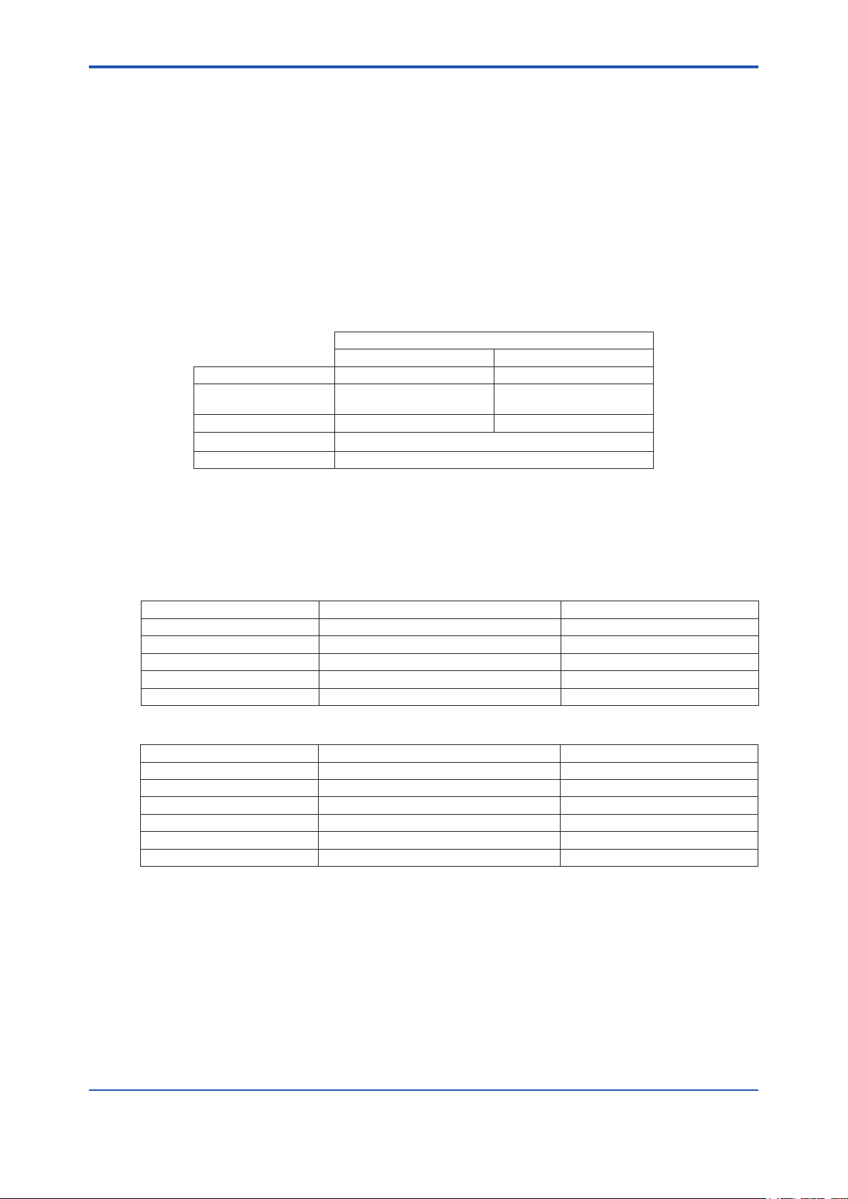
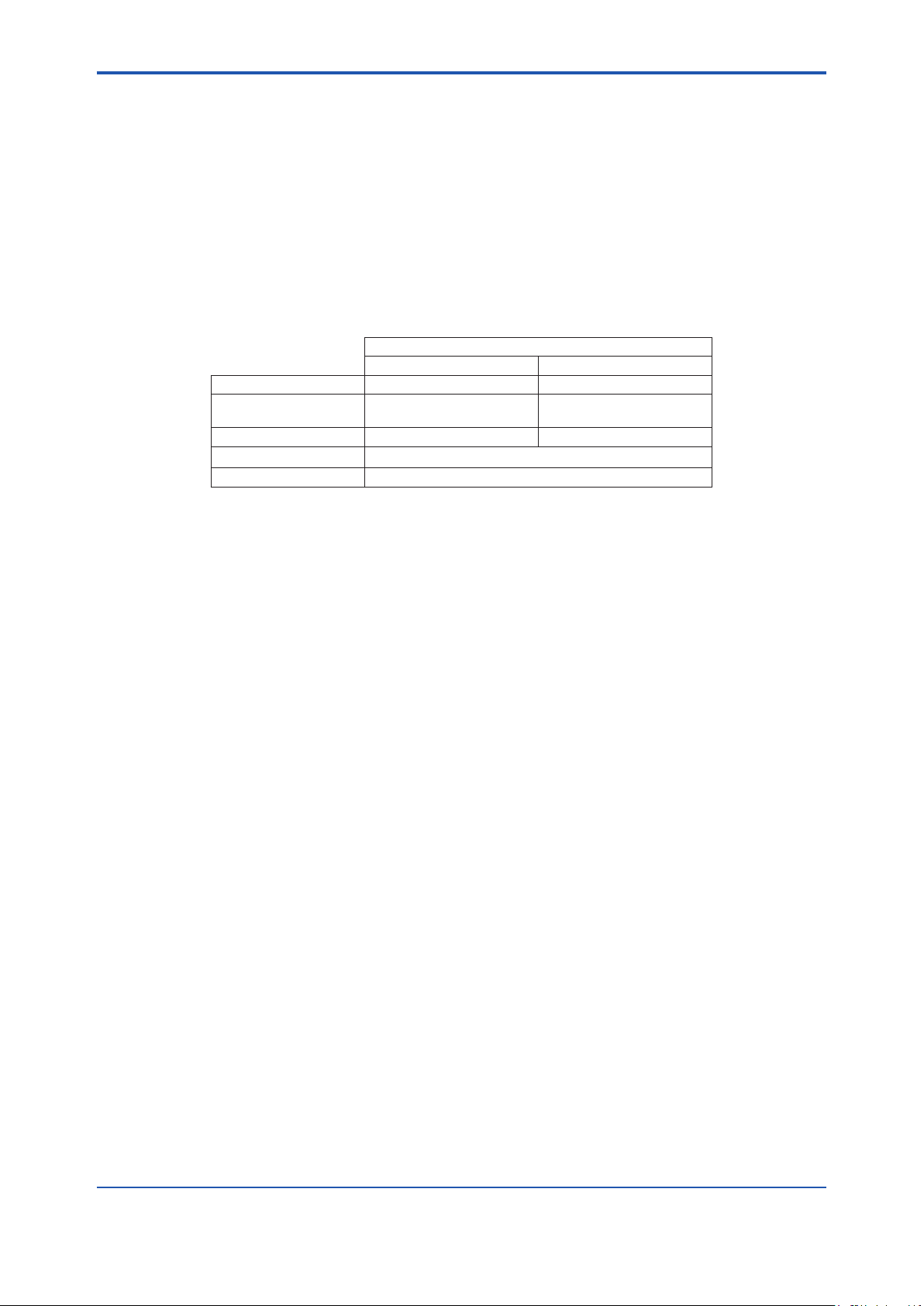
System Conguration of Chemical Cleaning pH Measuring System is as below;
Chemical Cleaning pH Measuring System
pH/ORP Converter 2-wire Analyzer
Chemical Cleaning unit PH8SM3-E PH8SM3-G or PH8SM3-F
pH analyzer PH450G FLXA202 or FLXA21
Distributor ― PH201G
pH sensor
Holder PH8HS3
(Note) You can select WTB10 Terminal Box, if necessary.
PH8EFP-□-TT2 (Note)
i
This document describes mainly PH8SM3 unit of the system and PH8HS3 Holder. For further
information on other products, please read corresponding manual attached to each product.
The related documents to each product:
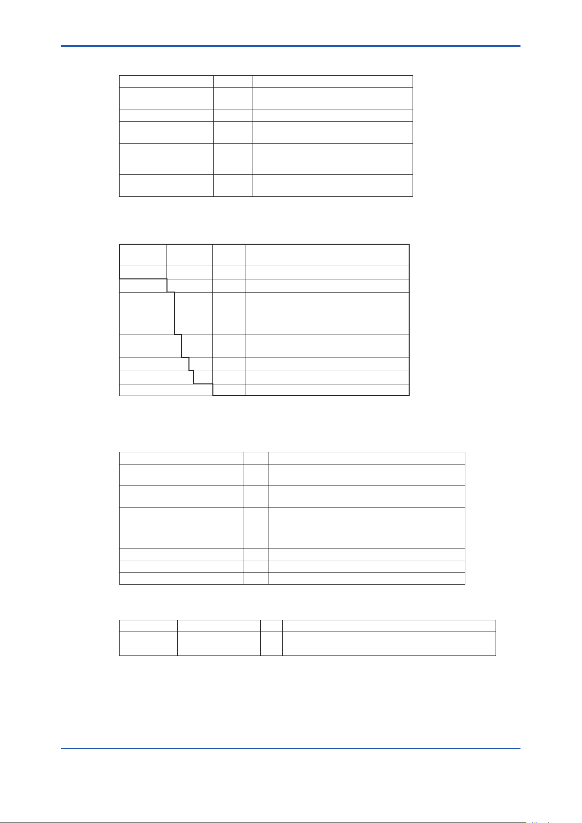
General Specications
Product Model Document Name Document number
PH8SM3, PH8HS3, PH201G Chemical Cleaning pH measuring System GS 12B7A1-E
PH450G PH450G pH and Redox (ORP ) Converter GS 12B07C05-01E
FLXA202 FLXA202 2-Wire Analyzer GS 12A01A03-01EN
FLXA21 FLXA21 2-Wire Analyzer GS 12A01A02-01E
PH8EFP, WTB10 pH and ORP Sensors GS 12B07B02-E
* the “E” or “EN” in the document number is a language code.
User’s Manual
Product Model Document Name Document number
PH8SM3, PH8HS3 Chemical Cleaning pH measuring System
PH450G PH450G pH and ORP Converter IM 12B07C05-01E
FLXA202, FLXA21 FLXA202/FLXA21 2-Wire Analyzer IM 12A01A02-01E
PH201G PH201G Distributor IM 19B01E04-02E
PH8EFP, PH8EFP, KCI Filling type pH sensor IM 12B7J1-01E
WTB10 WTB10-PH□ Terminal Box IM 19D01B01-01E
* the “E” in the document number is the language code.
n Notes on Handling User’s Manuals
IM 12B07W01-04EN(this document)
• Please hand over the user’s manuals to your end users so that they can keep the user’s
manuals on hand for convenient reference.
• Please read the information thoroughly before using the product.
• The purpose of these user’s manuals is not to warrant that the product is well suited to any
particular purpose but rather to describe the functional details of the product.
Media No. IM 12B07W01-04EN 1st Edition : Nov. 2016 (YK)
All Rights Reserved Copyright © 2016, Yokogawa Electric Corporation
IM 12B07W01-04EN 1st Edition : Nov. 11, 2016-00
Page 3

• No part of the user’s manuals may be transferred or reproduced without prior written
consent from YOKOGAWA.
• YOKOGAWA reserves the right to make improvements in the user’s manuals and product at
any time, without notice or obligation.
• If you have any questions, or you nd mistakes or omissions in the user’s manuals, please
contact our sales representative or your local distributor.
n Drawing Conventions
Some drawings may be partially emphasized, simplied, or omitted, for the convenience of
description.
Some screen images depicted in the user’s manual may have different display positions or
character types (e.g., the upper / lower case). Also note that some of the images contained in this
user’s manual are display examples.
n Inspection on delivery
Each component of Chemical Cleaning pH Measuring Systems comes in a separate package.
However, PH450G pH/ORP Converters (or FLXA202/FLXA21 2-Wire Analyzer ) are delivered
with factory-installed in PH8SM3 Chemical Cleaning pH Measuring Unit ,
After the delivery, open the package carefully and inspect for damages caused during transport.
Should there be any damage or breakage on the product, please contact YOKOGAWA
immediately and keep all the packing materials, containers and boxes that came with the
product.
ii
After the unpacking, make sure the delivered products include all of the component equipment
you ordered.
After completing the unpacking, make sure that the delivered component covers all of the
required specications. When conrming the specications, refer to the model and sufx codes
indicated on the nameplate on the instrument. The models are indicated on the name plates.
Check also those of accessories. For further information on PH8SM3 or PH8HS3, please read
subsection 1.2 of this document.
l Unpacking and handling
When unpacking, place the instrument on a level surface in the position in which the instrument
will actually be installed, (Do not allow the package to undergo any intense mechanical shock by
turning it over on its side.) Avoid applying any excess force to the pipes and cables. Otherwise, a
defective pipe and / or cable connection may result
PH8SM3 Chemical Cleaning pH Measuring Unit weighs approximately 50 kg. It is recommended
that the product be unpacked as near your installation location as possible.
IM 12B07W01-04EN 1st Edition : Nov.11, 2016-00
Page 4
u Safety Precautions
n Safety, Protection, and Modication of the Product
• In order to protect the system controlled by the product and the product itself and ensure
safe operation, observe the safety precautions described in this user’s manual. We assume
no liability for safety if users fail to observe these instructions when operating the product.
• If this instrument is used in a manner not specied in this user’s manual, the protection
provided by this instrument may be impaired.
• If any protection or safety circuit is required for the system controlled by the product or for
the product itself, prepare it separately.
• Be sure to use the spare parts approved by Yokogawa Electric Corporation (hereafter
simply referred to as YOKOGAWA) when replacing parts or consumables.
• Modication of the product is strictly prohibited.
• The following safety symbols are used on the product as well as in this manual.
WARNING
This symbol indicates that an operator must follow the instructions laid out in this manual in
order to avoid the risks for the human body and health including risk of injury, electric shock, or
fatalities. or the damages to instruments. The manual describes what special care the operator
must take to avoid such risks.
iii
CAUTION
This symbol indicates that the operator must refer to the instructions in this manual in order to
prevent the instrument (hardware) or software from being damaged, or a system failure from
occurring.
The following are signal words to be found only in our instruction manuals.
CAUTION
This symbol gives information essential for understanding the operations and functions.
NOTE
This symbol indicates information that complements the present topic.
n Warning and Disclaimer
The product is provided on an “as is” basis. YOKOGAWA shall have neither liability nor
responsibility to any person or entity with respect to any direct or indirect loss or damage arising
from using the product or any defect of the product that YOKOGAWA can not predict in advance.
n Trademark policy
FLEXA, FLXA, SENCOM are the registered trade marks and trade names of Yokogawa’s
products. All other company and product and product names mentioned in this document are
trade names, trademarks or registered trademarks of their representative companies. In this
document, trademarks or trade names are not indicated with TM or ® as trademark symbols.
IM 12B07W01-04EN 1st Edition : Nov. 11, 2016-00
Page 5

u After-sales Warranty
n Do not modify the product.
n During the warranty period, for repair under warranty, carry or send the product
to the local sales representative or service ofce. Yokogawa will replace or
repair any damaged parts and return the product to you. Before returning a
product for repair under warranty, provide us with the model name and serial
number and a description of the problem. Any diagrams or data explaining the
problem would also be appreciated.
• If we replace the product with a new one, we won’t provide you with a repair report.
• Yokogawa warrants the product for the period stated in the pre-purchase quotation
Yokogawa shall conduct dened warranty service based on its standard. When the
customer site is located outside of the service area, a fee for dispatching the maintenance
engineer will be charged to the customer.
n In the following cases, customer will be charged repair fee regardless of
warranty period.
• Failure of components which are out of scope of warranty stated in instruction manual.
• Failure caused by usage of software, hardware or auxiliary equipment, which Yokogawa
Electric did not supply.
• Failure due to improper or insufcient maintenance by user.
• Failure due to modication, misuse or outside-of-specications operation which Yokogawa
does not authorize.
• Failure due to power supply (voltage, frequency) being outside specications or abnormal.
• Failure caused by any usage out of scope of recommended usage.
• Any damage from re, earthquake, storms and oods, lightning, disturbances, riots, warfare,
radiation and other natural changes.
iv
n Yokogawa does not warrant conformance with the specic application at the
user site. Yokogawa will not bear direct/indirect responsibility for damage due
to a specic application.
n Yokogawa Electric will not bear responsibility when the user congures the
product into systems or resells the product.
n Maintenance service and supplying repair parts will be covered for ve years
after the production ends. For repair for this product, please contact the
nearest sales ofce described in this instruction manual.
IM 12B07W01-04EN 1st Edition : Nov.11, 2016-00
Page 6

Chemical Cleaning
pH Measuring System
IM 12B07W01-04EN 1st Edition
CONTENTS
u Introduction ....................................................................................................i
u Safety Precautions ......................................................................................iii
1. General ...................................................................................................... 1-1
1.1 Standard Specications ................................................................................... 1-1
1.2 Model and Sufx Codes ................................................................................... 1-4
1.3 External Dimensions ........................................................................................ 1-6
2. Installation ................................................................................................. 2-1
2.1 Installing the PH8SM3 Chemical Cleaning Unit for a Chemical Cleaning Sys-
tem ...................................................................................................................... 2-1
2.1.1 Where to install the unit ...................................................................... 2-1
2.1.2 Installation Facilities ........................................................................... 2-2
2.1.3 Installing Chemical Cleaning Unit ...................................................... 2-2
2.2 Installing the PH8HS3 Holder .......................................................................... 2-3
2.2.1 Where to install the holder ................................................................. 2-3
2.2.2 Installation Facilities ........................................................................... 2-3
2.2.3 Installing the PH8HS3 Holder ............................................................ 2-4
Toc-1
3. Piping and Wiring ..................................................................................... 3-1
3.1 Piping ................................................................................................................. 3-1
3.1.1 Line for Connecting Air Source .......................................................... 3-2
3.1.2 Line for Actuating Cylinder to Drive Sensor Pneumatically (Upward) 3-2
3.1.3 Line for Actuating Cylinder to Drive Sensor Pneumatically (Downward) 3-2
3.1.4 Line for Forced Feeding of Chemical Solution and Air-bubbling ....... 3-2
3.1.5 Line for Pressurizing KCl Reserve Tank ............................................ 3-2
3.2 Wiring ................................................................................................................. 3-3
3.2.1 Wiring for Intelligent Two-wire pH Transmitter System ......................3-4
3.2.2 Wiring system with 2-Wire Analyzer .................................................. 3-6
4. Operation ................................................................................................... 4-1
4.1 Names and Functions of Components ........................................................... 4-1
4.2 How the Chemical Cleaning pH Measuring System Works ......................... 4-3
4.2.1 Operating Modes ............................................................................... 4-3
4.2.2 WASH (Cleaning) Command .............................................................4-3
4.2.3 Wash Sequence .................................................................................4-4
4.3 Startup ................................................................................................................ 4-5
4.3.1 Inspection of Piping and Wiring ......................................................... 4-5
IM 12B07W01-04EN
1st Edition : Nov. 11, 2016-00
Page 7

Toc-2
4.3.2 Supplying Chemical Solution to Holding Tank ................................... 4-5
4.3.3 Supplying KCl Solution to Reserve Tank ........................................... 4-6
4.3.4 Adjustment of Pneumatic Pressure ................................................... 4-6
4.3.5 Setting Duration of Forced Feeding of Chemical Solution and Output of
CYLINDER FAIL Signal ..................................................................... 4-7
4.3.6 Supplying Power ................................................................................ 4-7
4.3.7 Entering Data Related to WASH Operation .......................................4-7
4.3.8 Verifying WASH Operation ................................................................ 4-8
4.3.9 Calibration with Standard Solution .................................................... 4-8
4.4 Regular Operation ............................................................................................. 4-8
4.4.1 Data Acquisition in Early Stages of Operation ................................... 4-8
4.4.2 Inspections During Regular Operation .............................................. 4-9
4.4.3 Behaviour During Power Failure/Restart ........................................... 4-9
4.4.4 Operation When Shutting Down the System ..................................... 4-9
4.4.5 Procedure When Restarting System Operation .............................. 4-10
5. Inspection and Maintenance ................................................................... 5-1
5.1 Inspection and Maintenance of Operating Unit for PH8SM3 Chemical Cleaning
System ............................................................................................................... 5-1
5.1.1 Inspection of Piping (between chemical cleaning chamber and holder) 5-1
5.1.2 Inspection of Solenoid Valves ............................................................ 5-1
5.1.3 Replacement of Fuses in the Power Supply Box .............................. 5-2
5.2 Inspection and Maintenance of PH8HS3 Holder ........................................... 5-2
5.2.1 Removing Foreign Matter from Wetted Part of Sensor Holder ......... 5-2
5.2.2 Inspecting Gasket on the Bottom Plate of Cleaning Chamber .......... 5-2
5.2.3 Cleaning and Lubricating Pneumatic Cylinder for Driving the Sensor
Holder ................................................................................................. 5-3
5.2.4 Inspecting O-rings on Sensor Holder ................................................ 5-4
5.2.5 Inspecting Terminal Block for Limit Switch .........................................5-4
6. Troubleshooting ....................................................................................... 6-1
6.1 More Than 100 ml of Chemical Solution at a Time Is Being Fed to Holder 6-1
6.2 A Smaller Quantity of Chemical Solution Is Fed to Holder .......................... 6-2
6.3 CYLINDER FAIL Signal Appears .....................................................................6-2
6.4 When Liquid keeps leaking from bottom plate of Cleaning Chamber ........ 6-2
6.5 Chemical Solution Cannot Be Fed into Cleaning Chamber ......................... 6-3
Customer Maintenance Parts List (PH8SM3).................. CMPL 12B07W01-13E
Customer Maintenance Parts List (PH8HS3)....................CMPL 12B07W01-23E
Revision Record .......................................................................................................i
IM 12B07W01-04EN 1st Edition : Nov. 11, 2016-00
Page 8
<1. General>
1. General
Chemical Cleaning pH Measuring System is designed to automatically clean pH electrodes
with a chemical solution while they remain in the system. The system is especially effective in
restoring the performance of a pH electrode which has been deteriorated through repeated
pH measurements of highly alkaline solutions. It is also effective in cleaning pH electrodes
contaminated with calcium sulfate (CaSO
1.1 Standard Specications
Chemical Cleaning pH Measuring System are congured as the table shown below.
pH/ORP Converter 2-wire Analyzer
Chemical Cleaning unit PH8SM3-E PH8SM3-G or PH8SM3-F
pH analyzer PH450G FLXA202 or FLXA21
Distributor ― PH201G
pH sensor
Holder PH8HS3
Note You can select WTB10 Terminal Box, if necessary.
The following are specication describing on PH8SM3 Chemical Cleaning Unit and PH8HS3
Holder. For more information on other products, please read corresponding instruction manuals
attached to each product.
) scale or calcium carbonate (CaCO3) scale.
4
Chemical Cleaning pH Measuring System
PH8EFP-□-TT2 (Note)
1-1
n PH8SM3 Chemical Cleaning Unit
Cleaning Method:
Automatic chemical cleaning by air bubbling
Interval Time:
0.1 to 36.0 hours (To be set in the pH converter)
Wash Time:
0.1 to 10 min (factory setting: 4 min)(To be set in the pH converter)
Relaxation Time:
0.1 to 10 min. (factory setting: 0.5 min.)(To be set in the pH converter)
Bubbling (SV1: On) Time:
0 to 10 min. (factory setting: Approx. 2 min.)
Cylinder Failure Time:
0 to 1 min. (factory setting: Approx. 0.5 min.)
Structure:
Freestanding rack for indoor installation.(For the uv protection,when you install the unit
outdoors, specify tank cover and select Fluoropolymer (PTFE) tube, or specify hood if
necessary.
Main Components:
Chemical solution tank, control box, air-pressure regulator, and power supply unit (for pH/
ORP Converter only)
IM 12B07W01-04EN 1st Edition : Nov. 11, 2016-00
Page 9

<1. General>
Chemicals for Cleaning:
Acid solution (e.g., hydrochloric acid or diluted sulfuric acid), or alkali solution. Organic
solvents are not allowed.
Note: Select appropriate solution for effective cleaning.
Material, Finish, and Color of Main Components:
Control Box (K9729AN)
Material: Aluminum alloy casting
Colors:
Deep sea moss green (Munsell 0.6GY3.1/2.0) and frosty white (Munsell 2.5Y8.4/1.2)
Finish: Baked polyurethane resin coating
Power Supply Unit (for pH/ORP converter only)
Material: Carbon steel (body)
Color: Deep sea moss green (Munsell 0.6GY3.1/2.0 or equivalent)
Finish: Baked polyurethane resin coating
Mounting Rack
Material: Carbon steel
Color: Deep sea moss green (Munsell 0.6GY3.1/2.0)
Finish: Baked polyurethane resin coating
Chemical Solution Tank (20 L, 2 to 10 % diluted hydrochloric acid or diluted sulfuric acid.
Effective capacity; approximately 17 L, approximately 100 ml is used for each cleaning)
Material: Polyethylene resin (for solution tank), and hard PVC resin (for internal tank)
Tubing for Solution, Air, or KCl
Material of tubes: Polyethylene or Fluoropolymer (PTFE)
Mateirial of tting (joint): polypropylene resin or Fluoropolymer (PTFE)
Ambient Temperature: 0 to 45°C (Note ; Freezing protection is required if necessary.)
1-2
Power Supply: 100 V AC ±10%, 50/60Hz ±5%
Power Consumption: Approx. 60 VA
2
Air Supply: 300 to 950 kPa {3 to 9.5 kg/cm
}
Max. Air Consumption: Approx. 10 Nl/min.
External Dimensions:
500 (W) x 600 (D) x 1630 mm (H)
Weight: Approx. 50 kg (when the chemical tank is empty)
Output Contact Signal: Cylinder failure
Contact State: Normally open (close on error )
Contact Capacity: 24 V DC, 1 A, 110 V AC 0.3 A (resistance load)
Output:
pH/ORP Converter : 4 to 20 mA DC 2 points (isolated transmission output; maximum load of
600 Ω)
2-Wire Analyzer : 1 to 5 V DC (minimum resistive load of 2 kΩ)
Cable Connection: G 1/2 gland packing is supplied.
Terminal Size: M4
Outside Cable Diameter: Φ9 to Φ12 mm
Piping Connection: Air for Instrumentation: Rc 1/4 female thread
Note 1: Install the KCl reserve tank in an appropriate place at the job site or attached to the stand for the
chemical cleaning unit.
IM 12B07W01-04EN 1st Edition : Nov 11, 2016-00
Page 10

<1. General>
1-3
Note 2: The wiring and piping between the chemical cleaning unit, sensor, KCl reserve tank, and holder are to
Note 3: The wiring between the switch in the holder and the chemical cleaning unit is to be done by the user.
be done by the user.
The terminal size is M4.
EMC Compliance: Korea Electromagnetic Conformity Standard Class A
A급 기기 (업무용 방송통신기자재)
이 기기는 업무용(A급) 전자파적합기기로서 판매자 또는
사용자는 이 점을 주의하시기 바라며, 가정외의 지역에서
사용하는 것을 목적으로 합니다.
n PH8SM3 Holder
Functions:
Moves the pH sensor up or down using a pneumatic cylinder (air cylinder), and provides
chemical cleaning.
Structure: Constructed for indoor use (
Max. External Dimensions:
190 (W) x 170 (D) x Approx. 830 to 2030 mm (H) (when the sensor is raised)
Mounting:
Mounted on a 2-inch (50A) vertical pipe (outside diameter: 60.5 mm). Two mounting
brackets are supplied.
pH Sensor Up/Down Movement (nominal):
한국 전자파적합성 기준
For outdoor installation, select Cylinder cover /SC as Option.)
300 mm, 600 mm, 1000 mm, 1500 mm
Weight:
Approx. 8 kg (holder with 300 mm movement)
Approx. 10 kg (holder with 600 mm movement)
Approx. 12 kg (holder with 1000 mm movement)
Approx. 15 kg (holder with 1500 mm movement)
Materials
Frame: Baking nish over staineless steel
Color: Deep sea moss green (Munsell 0.6GY3.1/2.0 or equivalent)
Bottom Cover Pull-up Mechanism: Rod (PPS resin) and screws (PEEK)
Mounting bracket: staineless steel
Holder: Polypropylene and hard PVC (for part of a holder)
Solution Chamber: Hard PVC
O-ring: Fluororubber
Gasket: EPDM
Solution Temperature Range: -5 to 80°C
Ambient Temperature: 0 to 45°C
Flow Speed: 2 m/s or less
Provide an adequate ventilation when using chemicals.
IM 12B07W01-04EN 1st Edition : Nov. 11, 2016-00
Page 11
<1. General>
1.2 Model and Sufx Codes
The name plate on product describes each specication of the product. The following are Model
and Sufx Code and their details on PH8SM3 and PH8HS3.
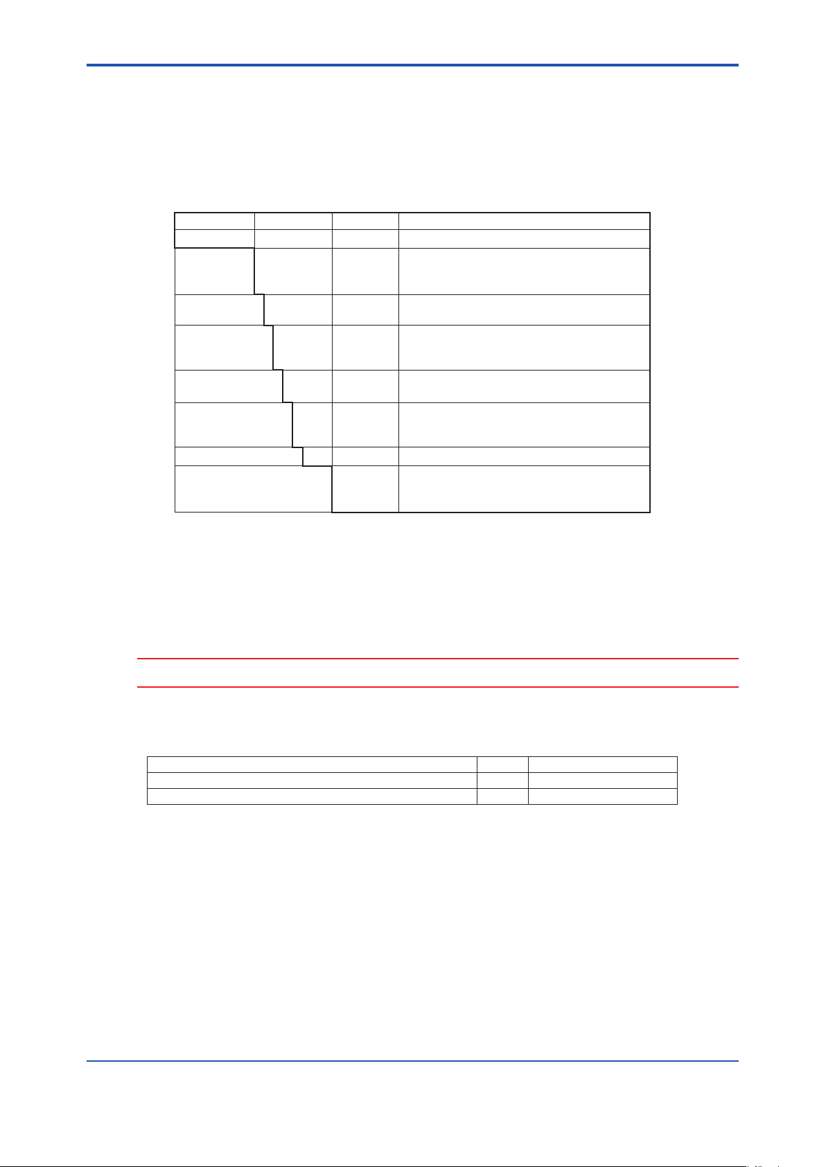
n PH8SM3 Chemical Cleaning Unit
●Model and Sufx Codes
Model Sufx code
PH8SM3 - - - - - - - - - - - - - - - - - - Operating Unit for Chemical Cleaning System
(*1)
-E
-F
-G
-TT2 - - - - - - - - Medium-pressure reserve tank *2
-NN
-PR
-NP
pH
measuring
system
KCl reserve
tank
Pressure
regulator for KCl
tank
Air connection -JP
Tubing for cleaning
chemicals
Style code *C - - - - - - - - Style C
Option /H
*1: The pH/ORP converter or 2-wire analyzer is attached to the chemical cleaning operating unit when shipped.
*2: For PH8EFP sensor, select KCl reserve tank (sufx code “-TT2”) with a medium-pressure.
*3: Polyethylene is susceptible to degradation upon UV radiation. Specify the Fluoropolymer (PTFE) (-T10) as tube
material, when you install PH8SM3 outdoors. Specify the Fluoropolymer (PTFE) when using PH8HS3 holder
outdoors, even though you install PH8SM3 unit indoors.
*4: Specied at the outdoor installation. Hood is made of precoated SEHC.
*5: Specied at the outdoor installation. The cover is made of non-coated stainless steel.
*6: For FLXA21 or FLXA202 with the sufx code -F, or -G, specify the type -AG (for general purpose for KC
-L10
-T10
Option code
- - - - - - - -
- - - - - - - -
- - - - - - - -
- - - - - - - -
- - - - - - - -
- - - - - - - -
- - - - - - - -
- - - - - - - -
- - - - - - - -
/TC
/KC
Specications
pH/ORP converter (PH450G)
2-wire Analyzer(FLXA21)
2-wire Analyzer(FLXA202)
None
Attached to the stand
Rc1/4
1/4 NPT female thread
Polyethylene (Connections: Polypropylene)
Fluoropolymer (PTFE)
(Connections: Fluoropolymer (PTFE))
With hood *4
With tank cover *5
for Korean Certicate *6
*3
1-4
).
CAUTION
The system must undergo start-up service when the chemical cleaning pH measuring system is installed.
l Accessories
Description Qt'y Remarks
6 (OD) x 4 (ID) polyethylene
Fitting (polyethylene resin or Fluoropolymer (PTFE)) 6 3 for joint, 3 for spare parts *2
*1: 1 tube for the control box-the chemical tank assembly
3 tubes for the PH8SM3-Ph8HS3
1 tube for the pressure valve-KCI reserve tank, if the operating unit has the pressure reducing valve for KCI.
Cut the tube into an approriate length to use.
*2: If the operating unit has a pressure-reducing valve that lowers the pressure on the KCl reserve tank, one of
these spare ttings is to be used for the piping port of the valve.
resin or Fluoropolymer (PTFE) tube
40 m
For tubing *1
IM 12B07W01-04EN 1st Edition : Nov 11, 2016-00
Page 12
<1. General>
l Spare Parts
Description P/N Remarks
Fuse for power supply
box
Polyethylene tubing
Fluoropolymer (PTFE)
tubing
Polypropylene tting
Fluoropolymer (PTFE)
tting
A1109EF Rating: 1A (for pH/ORP converter only)
L9901CA
L9901LG
L9831NA
L9831NE
L9831JE
L9831TS
L9831TT
Specied length by meters
Specied length by meters
L-shape tting (R1/8)
L-shape tting (R1/4)f
I-shape tting (R1/4)
L-shape tting (R1/8)
L-shape tting (R1/4)
n PH8HS3 Holder
●Model and Sufx Codes
Model Sufx
PH8HS3 - - - - - - - - - - - - - Holder for Chemical Cleaning
Material -PP - - - - - Polypropylene
Movement -03
pH measuring
system
Cleaning system -YP - - - - - Acid or alkali solutions can be used.
Style code *C - - - - - Style C
Option /SC Cylinder cover for outdoor use *1
*1: For outdoor installation, select Cylinder cover /SC as Option.
code
-06
-10
-15
-C
-T
Option
code
- - - - -
- - - - -
- - - - -
- - - - -
- - - - -
- - - - -
Specications
300 mm (with 2 mounting brackets)
600 mm (with 2 mounting brackets)
1000 mm (with 2 mounting brackets)
1500 mm (with 2 mounting brackets)
pH/ORP Converter
2-wire Analyzer
1-5
l Accessories
(other than mounting brackets and sensor holder)
Description Qt'y Remarks
M8 x 16 mm bolts and nut
Washers
U bolts (M8)
Washers and nuts
Rubber sheet (19 x 40 mm)
Plate
Clamp
M4, 16mm screw
Piping tting (polypropylene) 3 Parts for PH8SM3 holder (used for piping port)
Cable tie 5 For KCl supply tube/sensor cable
Spare gaskets (P/N: K9729WJ) 1 Parts for cleaning chamber of PH8HS3 holder
4/pkg
Parts for mounting brackets (used to mount to the
8
holder)
Parts for mounting brackets
2
(used to mount to 2-inch pipe)
4/pkg
1
Parts for sensor holder (used to x sensor cable)
1
1
1
l Spare Parts
Description P/N
Gasket K9729WJ
O-rings K9729YK
Qt'y
1
2
Remarks
Material : EPDM
1p/pkg. Replace both of the two rings at the same time.
IM 12B07W01-04EN 1st Edition : Nov. 11, 2016-00
Page 13
<1. General>
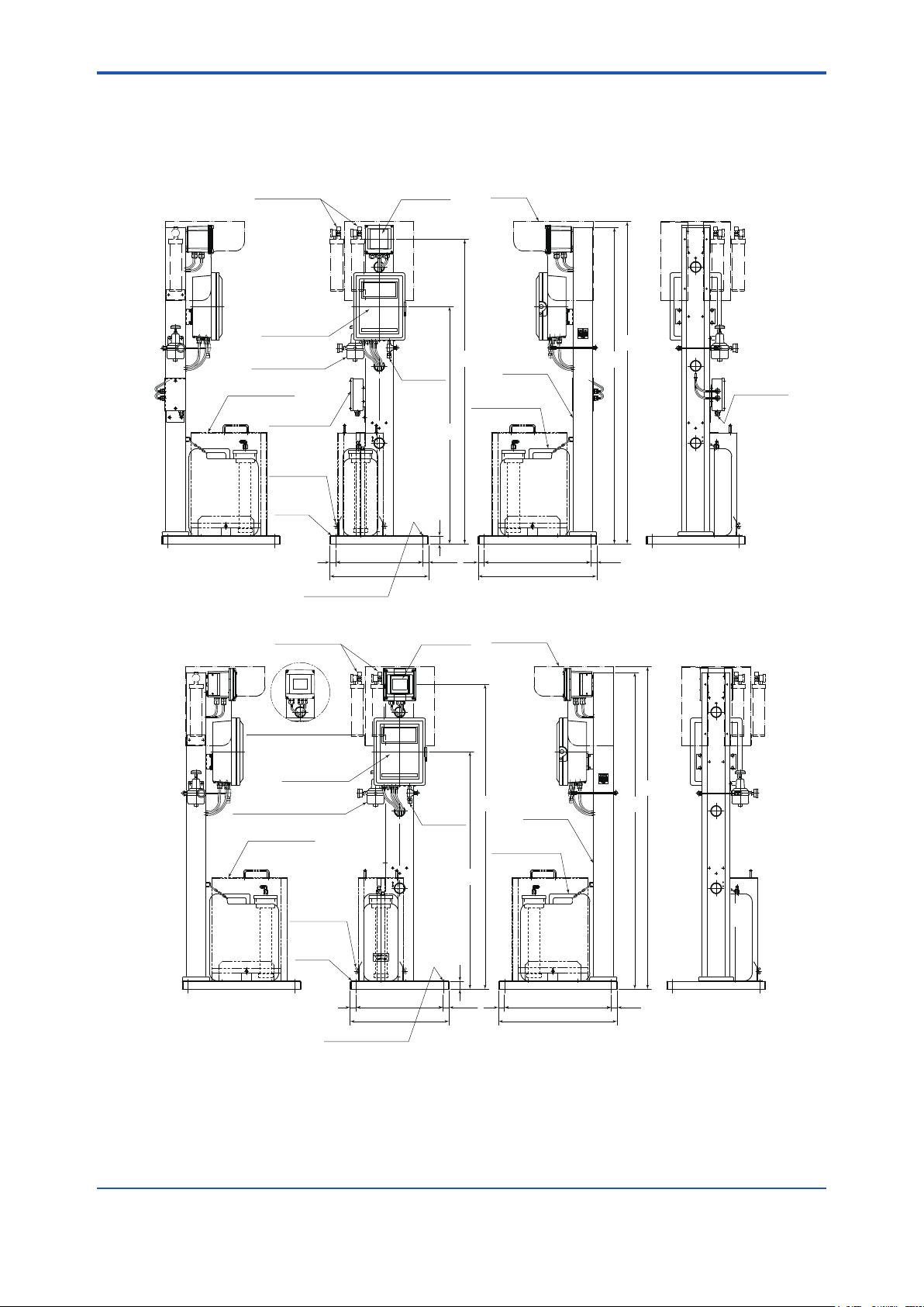
1.3 External Dimensions
n PH8SM3 Chemical Cleaning Unit
l pH/ORP Converter (PH8SM3-E)
)
Option
(
Hood
)
KCl reserve tank *1
an be installed
c
(
)
PH450G
Separated Order
(
1-6
unit:mm
Control Box
*2 Pressure Regulator
for KCI reserve tank
Tank Cover
Option
(
(AS3)
)
Power
Supply Unit
Air Inlet *3
(Rc1/4 or
1/4NPT)
Tank cover
fixing screws
option
(
)
PVC plate
30 440
500 600
4-Φ15fixing holes
l 2-Wire Analyzer (PH8SM3-G, -F)
KCI reserve tank *1
(Can be installed)
(Separated Order
FLXA21
Control Box
*2 Pressure Regulator AS3
for KCI reserve tank
(
Tank Cover
(Option)
fixing screws
)
)
Tank cover
(Option)
(1540)
(1200)
40
(30)
30 540
FLXA202
(Separated order)
Air Inlet *3
Rc1/4
(
or 1/4NPT
)
(1200)
Stand
SEHC
(
Chemical Solution
tank (20 L)
Hood(Option)
(1540)
SEHC
(
Chemical Solution
Tank (20 L)
)
Stand
1630
1600
Power Cable Inlet
Cable O.D.
(Φ9 ~ 11)
(30)
unit:mm
1630
1600
)
PVC plate
40
30 440
(30)
30 540
(30)
500 600
4-Φ15Fixing holes
*1: Mount the KCl solution reserve tank when necessary after installation. If the hood is specied, (Option code /H
is specied) mount the tank on the hood.
*2: This is a pressure valve to regulate the air that increases the pressure in the reserve tank for the KCl solution.
This valve is added only when specied.
*3: If no pressure valve is specied, there is no tube tting. Air inlet connects directly to piping port of the control
box.
IM 12B07W01-04EN 1st Edition : Nov 11, 2016-00
Page 14
<1. General>
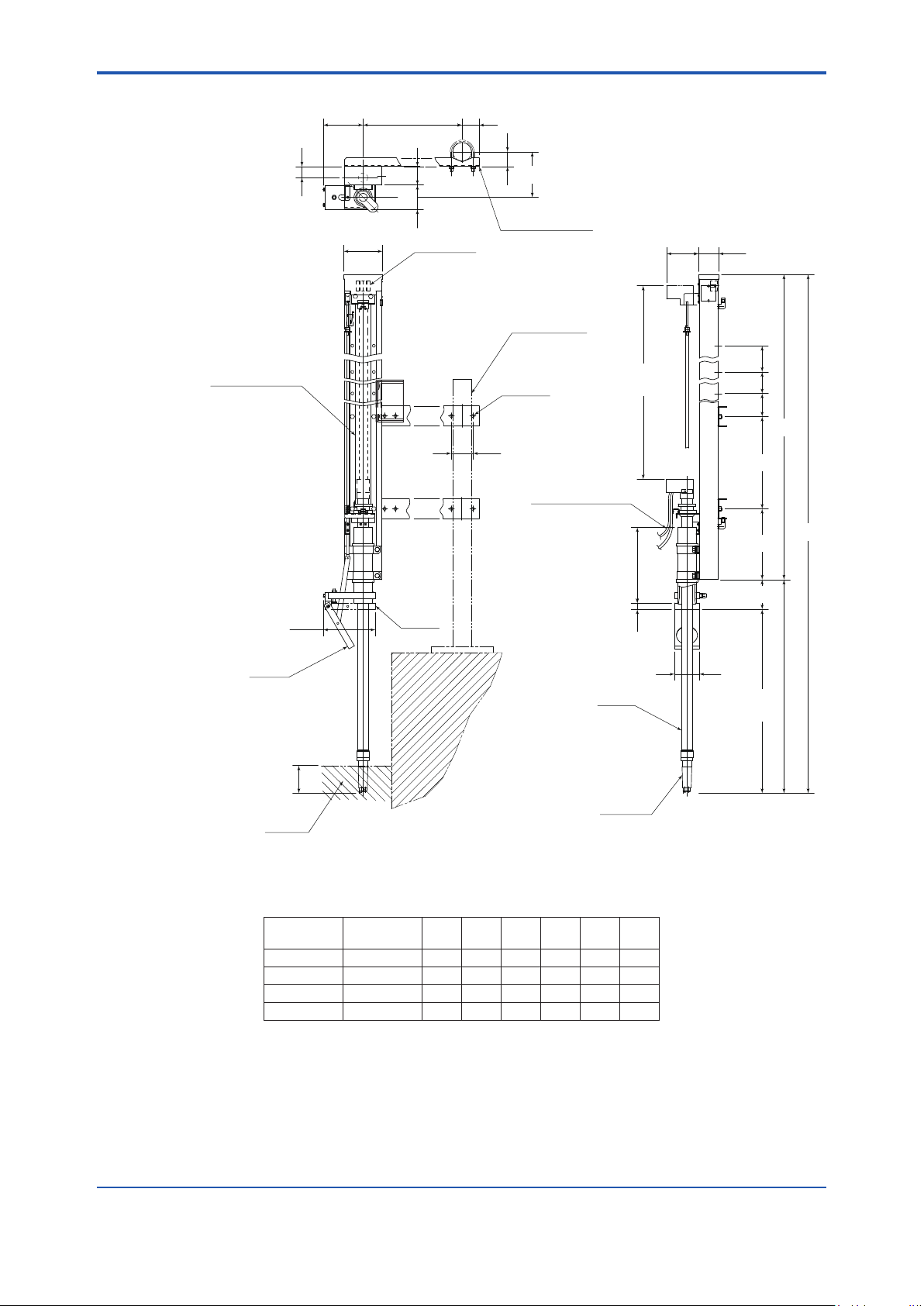
n PH8HS3 Holder
1-7
36
Cylinder Cover
(Option)
(130)
(126)
35 pitch
60
80
Grommet for
external wiring
55485 max.
48
(
70
Approx.150
Mounting bracket
with U-bolts
50A Pipe
provided by customer
2-Φ9 holes
Sensor cable
and KCI tube
Approx.110
)
Cylinder
Movement
247
(65)
C
B
L6
L5
L4
300
230
Unit: mm
L2
136
L1
(95)
A
80
L3
nominal movement
(170)
During
measurement
30mm or longer
Solution being measured
During
Cleaning
30379
During
measurement
pH electrode
20
Tubing Connections
A : Chemical solution inlet (Ø6/Ø4 tube joint)
B : Lower air inlet of cylinder (Ø6/Ø4 tube joint)
C : Upper air inlet of cylinder (Ø6/Ø4 tube joint)
Nominal
movement
300mm 340mm 1107 712 395 – – –
600mm 640mm 1707 1012 695 300 – –
1000mm 1040mm 2507 1412 1095 300 300 –
1500mm 1540mm 3507 1912 1595 300 300 300
Specify the nominal movement when ordering. L4, L5, and L6 designate the movable position for the pipe mounting bracket.
Note: ● Mounting bracket for holder will be shipped separately.
● Joint nipple will be attached with PH8SM3 Chemical Cleaning unit.
● For the outdoor installation, select /SC option of cylinder cover
Actual
movement
L1 L2 L3 L4 L5 L6
IM 12B07W01-04EN 1st Edition : Nov. 11, 2016-00
Page 15

Blank Page
Page 16
<2. Installation>
2. Installation
The chemical cleaning pH measuring system can be installed indoor/outdoors. Choose an
appropriate location (free from dust, sunlight, rain) for easy maintenance. Note that since the
system uses water for washing and a chemical solution, care must be taken to ensure that these
liquids are protected from freezing in winter.
Note: Install the PH201G distributor, which is required when using the 2-Wire Analyzer, in an
indoor location such as an instrument room.
This chapter explains the procedure for installing the component equipment, highlighting the
PH8SM3 Chemical Cleaning Unit for the chemical cleaning system and the PH8HS3 holder.
2.1 Installing the PH8SM3 Chemical Cleaning Unit for a Chemical Cleaning System
2.1.1 Where to install the unit
Install the PH8SM3 operating unit for a chemical cleaning system in a location which meets the
following requirements.
(1) Close to the pH measurement point (location where the PH8HS3 holder is installed)
2-1
The operating unit for the chemical cleaning system and the holder are connected via
electrical wiring as well as the piping through which the chemical solution is supplied. Keep
the length of the tubing for supplying the chemical solution to a minimum (less than 10 m) in
order to reduce piping resistance.
(2) The maximum tube length between the cleaning unit and the sensor holder is 10 m.
It is preferable to install the stand at the same level as the sensor holder. If this is impossible,
the stand can be installed a maximum of 2 m below the holder level. Installation above the
holder level causes no problem.
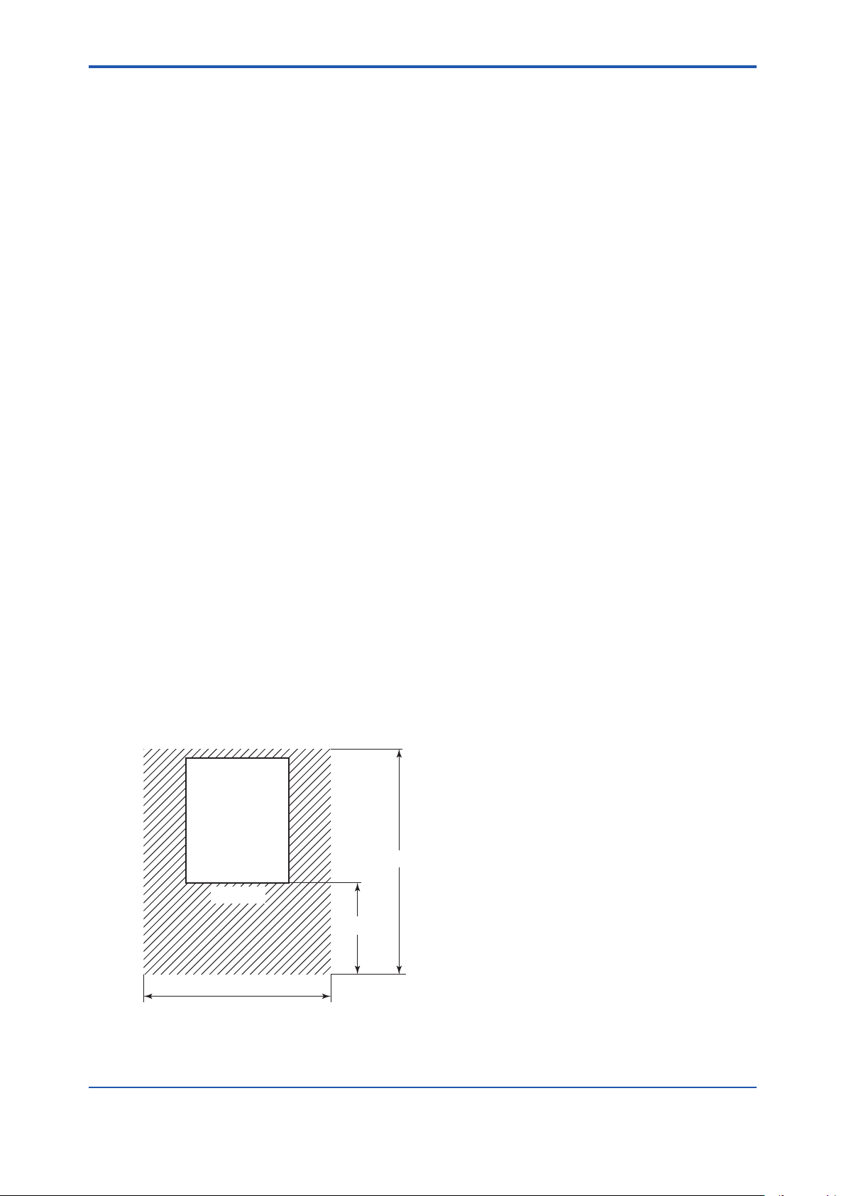
(3) Easy access for maintenance work
The location must allow users to have an easy view of the display on the PH450G pH/ORP
Converter or 2-wire Analyzer FLXA202/FLXA21, and to operate the control box with ease
to set the pressure. Also, consider the ease of work required when relling the holding tank
with the chemical solution. Furthermore, secure the clearance for maintenance access
shown in Figure 2.1.
Unit: mm
PH8SM3
Approx. 1150
Front view
Approx. 500
More than 900
Figure 2.1 Clearance for Maintenance Access
F2.1.ai
IM 12B07W01-04EN 1st Edition : Nov. 11, 2016-00
Page 17

<2. Installation>
(4) Ambient temperature is always maintained in the range of 0 to 45˚C
Check if there is any possibility that the cleaning chemical solution can freeze in winter or
if the pH/ORP Converter (or 2-Wire Analyzer) or the control box are subject to abnormal
temperature rises from direct sunlight. A location exposed to constant high humidity is not
desirable either.
(5) Free from vibration
The location must be free from such vibrations that might loosen piping connections.
(6) Free from corrosive gases
It is desirable that the location be free from any corrosive gas which may adversely affect
the components within the pH/ORP converter (or 2-Wire Analyzer) or the control box.
2.1.2 Installation Facilities
The PH8SM3 operating unit for the chemical cleaning system has a stand-alone construction
and can be securely attached with nuts to anchor bolts set in a concrete base.
l Construction of concrete base to install operating unit for chemical cleaning system
The PH8SM3 operating unit of the chemical cleaning system weighs approximately 60 kg when
the tank is lled with the chemical solution. Consequently, the facilities must be strong enough to
hold the weight of the entire unit. The facilities must also provide good drainage, Prepare anchor
bolts with M10 threads to secure the unit. Figure 2.2 shows how to set these anchor bolts in the
installation site.
2-2
Unit: mm
Dimensions of vat for operating unit of
M10 thread
Concrete base
Note: The holes (four) for the anchor bolts on the operating unit of the chemical cleaning system are 15 mm in diameter.
Figure 2.2 Setup of Anchor Bolts for Attaching Operating Unit of Chemical Cleaning System
chemical cleaning system
25
Approx. 60
540 600
Position of anchor bolt
Front view
440
500
F2.2.ai
2.1.3 Installing Chemical Cleaning Unit
After completing construction of the installation facilities, install the operating unit of the chemical
cleaning system. Tighten the nut securely (with nuts in all four locations.).
IM 12B07W01-04EN 1st Edition : Nov 11, 2016-00
Page 18

<2. Installation>
2.2 Installing the PH8HS3 Holder
2.2.1 Where to install the holder
The PH8HS3 holder must be installed in a location which is appropriate for pH measurement and
control and satises the following requirements.
(1) Safe and easy access for maintenance work.
This requirement must be satised since the holder is raised and removed when attaching/
detaching the pH sensor.
(2) Even in winter, the temperature must remain above that temperature at which the
chemical solution freezes.
Also, any condensation on the moving parts of the PH8HS3 holder cannot be allowed to
freeze.
(3) Protected from excessive dust in the air.
The presence of excessive dust may lead to an increased need to clean (removal of dust
from the cylinder).
2.2.2 Installation Facilities
The PH8HS3 holder is mounted on a 50A (OD: 60.5 mm) pipe installed in an upright position.
Provide the installation location with facilities to set the pipes and inserting sensors Special
attention must be paid to the following points when constructing these facilities:
2-3
l Position of pH measurement point (position of pH sensor) in relation to the
mounting pipe
Mounting pipe
pH sensor
Approx. 150
pH sensor
485 maximum
(Can be shorted in length of 205 mm by 35 mm pitch)
Figure 2.3 Position of pH Sensor in Relation to Mounting Pipe with Dimensions of Opening for
Inserting pH sensor
110 or more
160 or more
Machining of opening for inserting pH sensor
(for tanks with a covering)
60 or more
l Height (length) of mounting pipe
Position of upper mounting bracket
(Pitch: 300 mm)
Position of lower mounting bracket
More than 310
Covering (machined
to provide an opening)
Measured solution
Figure 2.4 Length (Height) of Mounting Pipe
P L
H
Ground
Mounting pipe
(OD: 60.5 mm)
Note: When employing a covering to prevent
the chemical solution from spattering,
refer to the dimensions of the opening
for inserting the pH sensor shown in
Figure 2.3.
Nominal Stroke L P H
300 mm 400 minimum 300 500 to 590
600 mm 700 minimum 300x2 500 to 890
1000 mm 1000 minimum 300x3 500 to 1290
1500 mm 1000 minimum 300x4 500 to 1790
Unit: mm
F2.3.ai
Unit: mm
F2.4.ai
IM 12B07W01-04EN 1st Edition : Nov. 11, 2016-00
Page 19

<2. Installation>
2.2.3 Installing the PH8HS3 Holder
Follow the procedure below to mount the PH8HS3 holder onto the pipe.
(1) Attach the mounting brackets (two pairs) to the holder by adjusting the position of the pH
sensor to satisfy the required distance to the pipe. To attach brackets, use the bolts (two
each), washers (four each) and nuts (two each) that with the holder.
(2) Assemble the U bolts, washers and nuts into the brackets (see Figure 2.5).
Nut
(Pipe)
U bolt
Figure 2.5 Parts for Mounting Bracket (Included)
Washer
Mounting bracket
Washer
Nut
Bolt (M8)
Washer
Chassis
F2.5.ai
2-4
(3) Assemble the PH8EFP pH sensor onto the sensor holder.
a. First remove the rubber cap on the top end of the sensor holder. Then thread the cable of
the pH sensor and the KCI supply tube from the bottom end of the sensor holder and then
pull them out from the top end.
b. Insert the pH sensor into the sensor holder so the sensor ange contacts the bottom end of
the sensor holder.
Note: Two O-rings are used to seal the openings of the sensor holder to prevent the
measured solution from leaking into the holder.
c. Using the supplied parts (plate, clamp, screw and rubber sheet), attach the given latch
mechanism to the sensor cable to prevent the sensor and sensor holder from coming apart
(see Figure 2.6).
KCl supply tube
Plate
Note:
·Fasten only the sensor cable with the clamp.
·Make sure that there is no slack in the sensor
cable inside the sensor holder.
Sensor cable
Rubber sheet (19 x 40 mm) [P/N K9729WE]
Attach the rubber sheet around the sensor cable
with the 40 mm length parallel with the cable.
Clamp
Screw
Sensor holder
Figure 2.6 Treatment to Prevent the pH Sensor from Coming Apart
d. Replace the rubber cap on the sensor holder.
e. Using the cable tie (included), securely fasten the sensor cable and the KCl supply tube to
the sensor holder. ( Figure 2.7)
IM 12B07W01-04EN 1st Edition : Nov 11, 2016-00
Page 20

<2. Installation>
Rubber cap
Sensor holder
Cable tie
Pass the cable tie through the
opening of the metal fitting
and then fasten the sensor cable
and, the KCI supply tube together.
KCl supply tube
Figure 2.7 Fixing the Sensor Cable and KCI Supply Tube
Metal fitting
Sensor cable
F2.7.ai
(4) Fix the PH8HS3 holder to the pipe
CAUTION
When installing the holder, avoid any contamination or moist/wet on the tip of the sensor cable.
2-5
When xing the holder, make sure both of the following requirements are completely satised:
• During measurement, the tip of the pH sensor must be submerged in the measured
solution.
Carefully observe any changes in the liquid level.
• The bottom plate of the holder’s cleaning chamber must not become wet with the
measured solution.
Contamination of the gasket on the bottom plate by the solution will lead to a decrease in the
gasket’s sealing capability.
CAUTION
When the bottom plate of the holder’s cleaning chamber is open, good ventilation must attend its use
to prevent the holder from corrosive gas.
Figure 2.8 illustrates the PH8HS3 holder when it is installed.
IM 12B07W01-04EN 1st Edition : Nov. 11, 2016-00
Page 21

<2. Installation>
Install the holder so the tip of the pH
sensor drops into the measured
solution to a depth of 30 to 90 mm.
2-6
Do not allow the bottom
plate of the cleaning
chamber to become
submerged in the
measured solution.
Measured
solution
Figure 2.8 Installed PHSHS3 Holder
Tank
Measured
solution
F2.8.ai
l Installing the medium-pressure KCl reserve tank
The KCl reserve tank supplied with the PH8EFP KCl-lling type pH sensor can be installed in the
operating unit for the chemical cleaning system (see Figure 1.1).
Note: Use an appropriate length of KCI supply tube for PH8EFP KCI supply PH sensor.
If installing the KCl reserve tank in other locations, choose a location which is higher than where
the cleaning chamber of the PH8HS3 holder is positioned.
Note This is important to maintain the normal position of liquid junction even when the supply of the pressurizing
air stops.
After completing installation of the KCl reserve tank, connect the KCl supply tube of the pH
sensor to the outlet of the KCI reserve tank.
l Submersion of pH sensor when the measured solution ows fast.
Rapid and continuous ow of measured solution can give the sensor holder distortion, which
hampers the ascent/descent motion of the holder, therefore the result of the measurement may
be affected. Appropriate installation must be guaranteed without distortion of the sensor holder.
If the ow of measured solution gives the sensor holder distortion, install the holder so the tip of
the pH sensor drops in to the solution to a depth of 30 to 90 mm. If this method is not available,
reduce the ow speed so that the distortion never occurs. For the stability of the measurement
result as well, the ow speed must be 2 m/sec or less at a measuring point.
IM 12B07W01-04EN 1st Edition : Nov 11, 2016-00
Page 22

<3. Piping and Wiring>
3. Piping and Wiring
3.1 Piping
The following lines must be provided to the chemical cleaning pH measuring system.
Lines (2) through (4) are polyethylene resin tubing or joints supplied with the system. Always
make sure that the length of each line is kept to a minimum (less than 10 m).
(1) Line for connecting air source
(2) Line for actuating cylinder to drive sensor pneumatically (upward)
(3) Line for actuating cylinder to drive sensor pneumatically (downward)
(4) Line for forced feeding of chemical solution and air-bubbling
(5) Line for pressurizing KCl reserve tank
Note: If you specify, polyethylene tube or Fluoropolymer (PTFE) tube of 40 m in length come with PH8SM3
with their corresponding tting.
If you do not use the piping materials that came with your system, refer to the notes given in
Subsection 5.1.1. Figure 3.1 shows the pipe lines in the system.
PH8SM3 Operating unit for chemical cleaning system
3-1
AS3
Internal tank
PG3
AS2
AS1
A
Air
Control box
PG2
PG1
SV1
B C D E
F G
Chemical solution
Tank (20 l)
SV2
Purge
(purge air outlet)
KCl tank (medium pressure)
(The KCl tank of the pH
sensor is used)
Dedicated tube
K
J
H
Process
liquid bath
PH8HS3
Holder
pH sensor
Pressure reduction valve
AS1:
for forced feeding of
chemical solution
Pressure reduction valve
AS2:
foe actuating cylinder
AS3:
Pressure reduction valve
(optional) for pressurizing
the KCl tank
PG1:
PG2:
PG3:
SV1:
SV2:
Figure 3.1 Piping Diagram
Pressure gauge
Pressure gauge
Pressure gauge (optional)
2-way solenoid valve
(N, C)
4-way solenoid valve
<Piping>
Air source connection
A:
Rc1/4 or 1/4NPT
Pneumatic line
B - F:
for forced feeding of
chemical solution
Pneumatic line raise
C - J:
the sensor holder
Pneumatic line to lower
D - K:
the sensor holder
Line for forced feeding
G - H:
of chemical solution
IM 12B07W01-04EN 1st Edition : Nov. 11, 2016-00
Page 23

<3. Piping and Wiring>
3.1.1 Line for Connecting Air Source
Air with a pressure of 300 to 950 kPa (3 to 9.5 kg/cm2) is supplied to the operating unit of the
chemical cleaning system. Use a steel or stainless steel line with an inner diameter greater than
6 mm to connect the air source to piping port “A” (air) in the control box.
Note : The piping port is Rc1/4 thread or 1/4 NPT female-thread (as specied when ordering).
The maximum air consumption is approximately 10 normal litter/min.
3.1.2 Line for Actuating Cylinder to Drive Sensor
Pneumatically (Upward)
This line is provided to allow the pH sensor to be withdrawn from the measured solution during
cleaning and then housed in the cleaning chamber. This line connects the holder (the piping
port labelled “J”) with the control box (piping port “C” [the lower section of the cylinder] ). Use the
tubing supplied with the system when connecting these ports.
3.1.3 Line for Actuating Cylinder to Drive Sensor
Pneumatically (Downward)
This line is provided to allow the pH sensor once housed in the cleaning chamber to be returned
to a measurement position after cleaning. This line connects the holder (the piping port labelled
“K”) with the control box (piping port “D” [the upper section of the cylinder]), Follow the same
piping procedure as that discussed in Subsection 3.1.2.
3-2
3.1.4 Line for Forced Feeding of Chemical Solution and Air-
bubbling
This line is provided to supply air for forced feeding of approximately 100 ml of the chemical
solution into the cleaning chamber during cleaning and then to bubble the chemical solution in
the chamber. During piping, connect the control box (piping port “B” [forced feeding of chemical
solution]) with the metering tank (piping port “F” [IN]) built in the holding tank for the chemical
solution, Also, connect the metering tank (piping port “G” [OUT]) with the holder (piping port “H”).
If the holding tank is positioned above the holder, always connect the tubing so at least a part
of the tubing is positioned above the cleaning chamber. Failure to observe this instruction may
result in the chemical solution fed to the cleaning chamber owing back into the holding tank after
air bubbling.
Follow the same piping procedure as that discussed in Subsection 3.1.2.
3.1.5 Line for Pressurizing KCl Reserve Tank
An air pressure of approximately 10 kPa (0.1 kg/cm2) is applied to the KCI reserve tank for the
pH sensor. Connect the outlet of the pressure reduction valve with the pneumatic connection
port of the KCI reserve tank. If so specied, the operating unit of the chemical cleaning system is
supplied with an “AS3” pressure reduction valve along with a polyethylene tube (10 m long) for
piping
IM 12B07W01-04EN 1st Edition : Nov 11, 2016-00
Page 24

<3. Piping and Wiring>
3.2 Wiring
The following six electrical connections must be provided to the chemical cleaning pH measuring
system. Note that slightly different wiring procedures are used depending on the system
conguration, either the intelligent two-wire pH transmitter system or the intelligent four-wire pH
converter system.
(1) Connection for pH sensor cable
Connect the pH sensor cable assembled in the PH8HS3 holder with the terminals of the
PH450G pH/ORP converter or 2-wire analyzers’ (FLXA202/FLXA212) terminals.
NOTE
The standard pH sensor cable is 3 m or 20 m long. If the PH8HS3 holder is located away from
the PH8SM3 operating unit at a distance greater than either of these lengths, it may become
necessary for you to use the PH8TBG/WTB10 terminal box through which this connection is
made.
(2) Connection for DETECT UPPER LIMIT signal (signal for detecting the upper limit of the
sensor holder’s position)
Connect the terminals of the PH8HS3 holder with the terminals of the control box in the
PH8SM3 operating unit.
3-3
(3) Connection for power supply and ground
For the intelligent four-wire pH converter system, set up power-supply connections with the
power supply box in the PH8SM3 operating unit. For the two-wire pH transmitter system, set
up power-supply connections with the terminals of the control box in the PH8SM3 operating
unit, Supply power to the PH201G distributor.
Note: The methods of power-supply connection (either a plug or terminal connection) differ
depending on the specications of the PH201G distributor. For further details, see the
IM19B01E04-02E user’s manual.
(4) Connection for pH signal
For the intelligent four-wire pH converter system, set up wiring for signal output on the
PH450G pH/ORP converter.
For the two-wire pH transmitter system, set up connection (for a transmission signal)
between the PH202G intelligent pH transmitter and the PH201G distributor, with the wiring
for an output signal provided to the PH201G distributor.
(5) Connection for contact output of CYLINDER FAIL signal
Set up this connection with the control box in the PH8HS3 operating unit.
(6) Connection for contact input of WASH (cleaning) signal
This connection is essential for the two-wire pH transmitter system. Set up the connection
between the control box and the PH201G distributor.
Note: For the four-wire pH converter system, connect the control box with the PH450G pH /
ORP converter (this connection is already made before shipment).
IM 12B07W01-04EN 1st Edition : Nov. 11, 2016-00
Page 25

<3. Piping and Wiring>
3.2.1 pH/ORP Converter System
Figure 3.2 illustrates electrical connections for pH/ORP converter system.
PH450G
Output signal
(4 to 20 mA DC, HART)
Output signal
(4 to 20 mA DC)
Remote
Contact input
Air Cylinder
21
22
Jumper
mA1
mA2
CONTACT
IMP.LOW
13
11
12
14
15
16
POWER
S1
S2
S3
S4
(Failsafe)
NC
NO
NC
NO
NC
NO
NC
NO
1
2
C
C
C
C
3-4
pH
Holder
1
2
pH Sensor
Position signal
PH8SM3
Control Box
8
9
Ground to earth
4
5
6
7
1
2
3
Cleaning signal
A1 A2
L1
L1
L2
L2
Power
supply unit
Cylinder failure signal
wiring by customer
100V AC
Figure 3.2 Wiring for pH/ORP Converter (PH8SM3-E)
(1) Connection for pH sensor cable
Connect the sensor cable so that the code on each core wire matches the corresponding
code on the PH450G pH/ORP Converter. For more information about sensor cable
connection, see the user’s manual “PH450G pH/ORP Converter.” Also refer to “WTB10
Relay Terminal Box” user’s manual if your system uses a relay terminal box.
CAUTION
The sensor cable and the KCI supply tube move up and down in synchronization with the sensor
holder along the PH8HS3 holder. No slack in cable or tube is allowed. Provide an installation
location to ensure that a smooth up-and-down motion takes place. The cable or tube may be
damaged if, during the up-and-down motion, it comes into accidental contact with the PH8HS3
holder or other structures.
(2) Connection for DETECT UPPER LIMIT signal (signal for detecting the upper limit of
sensor holder’s position)
Use a two-core cable with an outer diameter of 9 to 12 mm for this connection. Treat both
ends of each cable core so they t M4 threads. Connect terminal 1 of the terminal block for
the limit switch of the PH8HS3 holder to terminal 8 of the control box, and terminal 2 with
terminal 9.
Note: There will not be a problem if you connect terminal 1 with terminal 9 and terminal 2 with
terminal 8.
The cable inlet of the PH8HS3 holder is located on the right-hand side of the chassis’s upper
section. When wiring the cable, loosen the two screws and remove the cover (for protection
against drips). After the completion of wiring, always make sure the cover is reinstalled in
place.
IM 12B07W01-04EN 1st Edition : Nov 11, 2016-00
Page 26

<3. Piping and Wiring>
(3) Connection for power supply and ground
<Connection for power supply>
A power supply voltage of 100 V AC ±10%, 50/60 Hz is applied to the power supply unit of
the chemical cleaning pH measuring system.
CAUTION
Chemical Cleaning pH Measuring System has no power switch. To avoid the possible hazard of
electrical shock or damage to the instrument, always install a power switch (double-pole) in the
power line.
NOTE
The fuse (1 A) in the power supply unit is installed for the pH/ORP converter. (The pH/ORP
converter itself contains an additional power-line fuse (0.1 A)).
Use a two-core cable with an outer diameter of 9 to 12 mm for this connection. Treat both
ends of each core wire of the cable extending from the power supply so they t M-4 thread
and then connect them with terminals L1 and L2 of power supply unit.
3-5
<Connection for ground>
The control box and pH/ORP Converter of the system must be grounded with a grounding
resistance of less than 100Ω). The grounding terminal of the control box can be found in the
bottom of the control box casing. The grounding terminal of the pH/ORP Converter can be
found in the bottom of the control box casing.
(4) Connection for contact output of CYLINDER FAIL signal
PH8SM3 Chemical Cleaning System outputs a CYLINDER FAIL contact signal. This
contact signal is output to let the operator know that a failure has occurred in the upward
movement of the pneumatic cylinder of the PH8HS3 holder. The system uses the DETECT
UPPER LIMIT signal (the signal for detecting the upper limit of the sensor holder’s position)
discussed in step 2 above for this purpose.
The CYLINDER FAIL contact signal is given if the DETECT UPPER LIMIT signal is not
present even if the setting for timer T1 in the control box is reached. This connection is
applied when the above function is used. Use a two-core cable with an outer diameter of 9
to 12 mm for this connection. Treat both ends of each core wire of the cable so they t M4
threads and then connect terminals 6 and 7 of the control box with the instrument being
used, such as an annunciator. For the contact capacity and other details, see subsection
1.1.
(5) Connection for pH signal
PH450G pH/ORP Converter sends two 4 to 20 mA signal (pH, temperature) and receives
the contact input for cleaning start. Use a two-core cable with a nished outer diameter
of 9 to 12 mm for this connection. For the output signal from pH/ORP Converter, connect
the terminals “mA1 +” or “mA1 -” to those corresponding terminals at the receiving
instrument. For the second output signal, connect the terminals “mA2 +” or “mA2 -” to those
corresponding terminals at the receiving instrument.The terminal CONTACT on a pH/ORP
Converter is for connection of remote contact input. For cable shield, connect a cable to the
terminal SHLD.
CAUTION
Connect the cable shield to the grounding at pH/ORP converter.
IM 12B07W01-04EN 1st Edition : Nov. 11, 2016-00
Page 27

<3. Piping and Wiring>
(6) Connection for contact input of WASH (cleaning) signal
It is already been wired.
3.2.2 Wiring system with 2-Wire Analyzer
Figure 3.3 illustrates wiring the system with 2-Wire Analyzer.
3-6
PH201G
Distributor
A(+)
(+)C
B(
(
-)
-)D
e
f
Output signal
(1-5V DC)
100V AC
pH
Holder
1
2
pH sensor
Air Cylinder
Position signal
FLXA202 or FLXA21
13
+
12
-
11
14
15
16
PH8SM3
Control box
4
5
6
8
7
9
1
2
3
Cleaning Signal
Cylinder failure signal
Wiring by customer
100V AC
Figure 3.3 wiring for 2-Wire Analyzer (PH8SM3-G, -F)
(1) Connection for pH sensor cable
Connect the sensor cable so that the code on each core wire matches the corresponding
code on 2-Wire Analyzer; FLXA202 or FLXA21. For more information about sensor cable
connection, see the user’s manual on “FLXA 202/FLXA21 ” Also refer to “WTB10 Relay
Terminal Box” user’s manual if your system uses a relay terminal box.
CAUTION
The sensor cable and the KCI supply tube move up and down in synchronization with the sensor
holder along the PH8HS3 holder. Give adequate consideration to any slack in the cable or tube
and to the installation location to ensure that a smooth up-and-down motion takes place. The
cable or tube may be damaged if, during the up-and-down motion, it comes into accidental
contact with the PH8HS3 holder or other structures.
(2) Connection for DETECT UPPER LIMIT signal
Use a two-core cable with an outer diameter of 9 to 12 mm for this connection. Treat both
ends of each core wire of the cable so they t M4 threads and then connect terminal 1 of the
terminal block for the limit switch of the PH8HS3 holder with terminal 8 of the control box,
terminal 2 with terminal 9.
Note: There will not be a problem if you connect terminal 1 with terminal 9 and terminal 2 with
terminal 8.
The cable inlet of the PH8HS3 holder is located on the right-hand side of the chassis’s upper
section. When wiring the cable, loosen the two screws and remove the cover (for protection
against drips). After the completion of wiring, always make sure the cover is reinstalled in
place.
IM 12B07W01-04EN 1st Edition : Nov 11, 2016-00
Page 28

<3. Piping and Wiring>
(3) Connection for power supply and ground
<Connection for power supply>
A power supply voltage of 100V AC ±10%, 50/60 Hz is box of the PH8HS3 operating unit of
the chemical cleaning system.
CAUTION
The chemical cleaning pH measuring system has no power switch. To avoid the possible hazard
of electrical shock or damage to the instrument, always install a power switch (double-pole) in the
power line.
Use a two-core cable with an outer diameter of 9 to 12 mm for this connection. Treat both
ends of each core wire of the cable extending from the power supply so they t M4 thread
and then connect them with terminal1 and 2 on the control box. For information on the
distributor power supply, refer to the user’s manual “PH201G Distributor”.
Note Power voltage or connection varies depending on the specication of distributors.
<Connection for ground>
The control box and pH transmitter of the chemical cleaning pH measuring system must
be grounded with a grounding resistance of less than 100Ω. The grounding terminal of
the control box can be found in the bottom of the control box casing. As for the grounding
terminal of the 2-Wire Analyzer, refer to the corresponding instruction manual.
3-7
(4) Connection for contact output of CYLINDER FAIL signal
The chemical cleaning system outputs the CYLINDER FAIL contact signal. The contact
signal is output to let the operator know that a failure has occurred in the upward movement
of the pneumatic cylinder of the PH8HS3 holder. The system uses the DETECT UPPER
LIMIT signal discussed in step 2 above for this purpose.
The CYLINDER FAIL contact signal is given when DETECT UPPER LIMIT is not signaled
even if the setting for timer T1 in the control box is reached. This connection is applied
when the above function is used. Follow the same procedure as for the two-wire pH
transmitter system. Use a two-core cable with a nished outer diameter of 9 to 12 mm for
this connection. Treat both ends of each core wire of the cable so they t M4 threads and
then connect terminals 6 and 7 of the control box with the instrument being used, such as an
annunciator.
Note: For the contact capacity and other details, see Subsection 1.1.
(5) Connection for pH signal
To PH201G distributor, 2-Wire Analyzer FLXA202 or FLXA21 sends a 4 to 20 mA output
signal and 2 mAp-p <WASH> signal which is superimposed on the 4 to 20 mA DC signal.
The distributor outputs 1 to 5 V DC signal. Use a double-core shielded cable with a nished
outer diameter of 9 to 12 mm for this connection. For wiring between 2-Wire Analyzer and
the distributor, connect + terminal of 2-Wire Analyzer to terminal A of the distributor, and
connect a minus terminal to terminal B. Shiled of cables must be connected to the ground
terminal G of the 2-Wire Analyzer.
Connect output cables to each corresponding terminal on the distributor or receptor, such as
terminal C, or D. Shield of cables must be grounded on each receptor side.
(6) Connection for contact input of WASH (cleaning) signal
Use a double-core shielded cable with a nished outer diameter of 9 to 12 mm for this
connection. Treat both ends of each core wire of the cable so they t M4 threads and then
connect terminals 4 and 5 of the control box with the distributor terminal e and terminal f.
IM 12B07W01-04EN 1st Edition : Nov. 11, 2016-00
Page 29

Blank Page
Page 30

<4. Operation>
4. Operation
This chapter gives an overview of the functions and operations of the components the system
along with their names and explains the start-up procedure required implement optimum cleaning
4.1 Names and Functions of Components
n PH8SM3 Chemical Cleaning Unit
(Reserver tank for KCl solution)
4-1
(pH/ORP converter)
(2-Wire Analyzer)
Pressure reduction valve AS3
Sets the pressure of the air that
pressurizes the KCl reserve tank.
(Supplied when specified accordingly.)
Power supply box
(Supplied with the pH/ORP
converter system for outdoor use.)
Holding tank for chemical solution
A tank (with an effective capacity
of approximately 17 liters) to contain
a chemical cleaning solution.
Awning hood
Protects against an abnormal
temperature rise in the pH converter
(or the pH transmitter) or the control box
due to direct sunlight (Supplied when
specified accordingly.)
Control box
Controls the operation sequence of
the chemical cleaning pH measuring system.
Tank cover
Optional for outdoor use,
to protect against UV rays.
Pressure gauge (PG1)
Indicates the air pressure for forced
feeding of the chemical solution.
Pressure reduction valve (AS1)
Sets the air pressure for forced
feeding of the chemical solution.
Timer (T2)
Sets the time required to air-bubble
the chemical solution within the
cleaning chamber during cleaning.
Control Box
Pressure gauge (PG2)
Indicates the air pressure for
actuating the pneumatic cylinder.
Pressure reduction valve (AS2)
Sets the air pressure for actuating
the pneumatic cylinder.
Manuel cleaning commend switch
When turned on, this switch initiates
the cleaning sequence; when turned off,
it shuts down the sequence.
Figure 4.1 Names and Functions of Components in PH8SM3 Chemical Cleaning System
IM 12B07W01-04EN 1st Edition : Nov. 11, 2016-00
Page 31

<4. Operation>
n PH8SM3 Holder
4-2
Terminal block
for limit switch
Limit switch
Senses that the
upper limit of the
sensor holder's
position is reached.
Spring
helps the bottom plate
of cleaning chamber
to tightly close during
cleaning.
Drip-proof cover protects against rain or dust.
Cable inlet
Allows the cable (for the signal
which detects the upper limit of
the sensor holder's position)
to get through to the terminal
block for the limit switch.
Optional pneumatic cylinder cover,
to protect against dust.
Arm to support sensor holder
The sensor holder is installed
by simply inserting it into this arm.
Air connection part for
actuating pneumatic
cylinder (downward)
Mounting bracket
Used to mount the PH8HS3
holder to a two-inch pipe.
Pneumatic cylinder
Slider of pneumatic
cylinder
Goes up or down
pneumatically.
Air connection part for
actuating pneumatic
cylinder (upward)
Bottom plate of
cleaning chamber
Closes during cleaning
to hold the chemical
solution supplied from the
tank within the cleaning
chamber.
Cleaning chamber
Accommodates the
pH sensor during cleaning
and allows the sensor
electrodes to be cleaned.
(pH sensor)
Piping port for forced
feeding of chemical solution
Sensor holder
Holds the pH sensor.
The sensor holder goes up
or down along with the slider
of the pneumatic cylinder.
O-ring
Protects the holder from
precipitation of solutions
Figure 4.2 Names and Functions of Components in PH8HS3 Holder
(Note) When you remove the sensor holder out of the unit during calibration or for some reasons,
take off the cover on the upper chassis. However, put the cover back to where it was to maintain
the isolation of limit switch terminals and prevent operation errors.
l How the slider of air cylinder moves
The slider of air cylinder moves up and down by the strength of magnet inside the pneumatic
cylinder. Stain or dust around the air cylinder hampers a smooth sliding of the cylinder. We highly
recommend the installation of cylinder be guaranteed in a clean environment.
IM 12B07W01-04EN 1st Edition : Nov 11, 2016-00
Page 32

<4. Operation>
4.2 How the Chemical Cleaning pH Measuring System Works
4.2.1 Operating Modes
There are two operating modes in the chemical cleaning pH measuring system: the
measurement mode and cleaning mode.
l Measurement mode
The system performs pH measurement. The sensor holder is in its lowest position, submerging
the pH electrodes in the chemical solution.
l WASH (Cleaning)mode
The sensor holder begins rising from its lowest position by way of the wash command, performs
cleaning of the pH electrodes and then goes into the measurement mode again. The cleaning
mode includes the relaxation interval required after the washing sequence. In the wash mode, it
is possible to hold the output signal as a certain value, such as the last value before the WASH
mode starts.
4.2.2 WASH (Cleaning) Command
4-3
WASH command in normal operation is issued from the pH/ORP converter or the 2-Wire
analyzers at the intervals set in these instruments. For the pH measuring system for outdoor use,
the WASH command can be issued on demand using a remote contact input. A WASH command
sent from the pH/ORP converter or 2-wire analyzers consists of two time elements, i.e., the
washing time and the relaxation interval.
Chemical cleaning can also be implemented using the MANUAL Wash (cleaning) switch in the
control box. Turning on this switch causes the chemical cleaning pH measuring system to enter
the wash mode; turning off causes the system to exit from the wash sequence. Note that, when
washing is carried out using the MANUAL WASH switch, neither the pH/ORP converter nor the
2-Wire analyzer performs the functions (such as a holding of the output signal) available in the
wash mode.
If there is a conict between a WASH command sent from the pH/ORP converter or 2-wire
analyzer and the same command issued with the MANUAL WASH switch in the control box, the
sensor holder behaves according to the timing diagram shown in Figure 4.3.
pH/ORP Converter or 2-Wire
Analyzer
WASH signal (automatic cleaning)
MANUAL WASH switch on
Sensor holder
Highest position
Lowest position
Power on
Washing time
Interval between wash
Relaxation interval
Interval between wash
Holding of pH output signal
(WASH mode)
Note:
The interval between wash, washing cycle(time) and relaxation interval are set on the pH/ORP Converter or
2-Wire Analyzer. Hold of the pH output signal is implemented only in the washing sequence
(WASH mode) initiated by a command issued from the pH/ORP converter or 2-Wire Analyzer.
Hold can be off, too. Forced air feeding / Air bubbling of chemical solution continues for a determined length of time ( set in Timer T2) only after
the sensor holder moves from Lowest position to Highest position.
Figure 4.3 Behaviour of the Sensor Holder If There Is a Conict Between the Automatic-
WASH Command and Manual-WASH Command
Air for forced feeding of chemical solution
IM 12B07W01-04EN 1st Edition : Nov. 11, 2016-00
Page 33

<4. Operation>
4.2.3 Wash Sequence
Figure 4.4 shows the actions that the system implements to clean the electrodes when
it receives a WASH (cleaning) command from either PH450G or FLXA202/FLXA21.
Holding of pH output signal
WASH
Chemical cleaning system
SV2 solenoid valve for
actuating cylinder
Sensor holder
Bottom plate of
cleaning chamber
DETECT UPPER LIMIT
signal
CYLINDER FAIL signal
SV1 solenoid valve for
forced feeding of chemical
solution and air bubbling
pH meter
Highest position
Lowest position
Closes
Opens
(Measurement mode) (Measurement mode)
Contact signal
for WASH
Air is injected to raise the cylinder
t1≥
t1<
(WASH mode)
WASH
When can not reach
the highest position.
Open (air is fed to the metering tank.)
t2
Relaxation
4-4
t1: Setting of timer T1 t2: Setting of timer T2
Figure 4.4 WASH Sequence
l Output of WASH (cleaning) signal
When the setting the interval between WASH (in pH/ORP Converter or 2-Wire Analyzer ) times
out, the system enters the WASH sequence. The WASH signal is then output to the control box
of the operating unit in the chemical cleaning system for the period equivalent to the value set in
the timer.
l Actuation of SV2 solenoid valve
The SV2 solenoid valve in the control box is active while it is receiving the WASH signal. This
causes a pneumatic pressure to be applied to the port that raises the cylinder on the PH8HS3
holder. Consequently, the sensor holder goes up in conjunction with the cylinder slider.
l Output of DETECT UPPER LIMIT signal and CYLINDER FAIL signal
When the sensor holder reaches the upper limit, the bottom plate of the cleaning chamber closes
and the limit switch is turned on. The ON signal from the limit switch then starts timer T2 in the
control box, causing solenoid valve SV1 to be actuated (the valve is opened). Solenoid valve
SV1, when opened, causes a pneumatic pressure to be applied to the interior of the metering
tank, resulting in an approximately 100 ml of the chemical solution being forced into the cleaning
chamber of the holder. The air is kept supplied until timer T2 times out, bubbling the chemical
solution within the cleaning chamber to enhance the cleaning of the pH sensor electrodes.
Note that if the sensor holder does not reach the upper limit when timer T1, which starts at the
same time the WASH signal is output, is timed out, the CYLINDER FAIL signal is given. This
signal stops (the contact opens) when the WASH contact signal is no longer present.
IM 12B07W01-04EN 1st Edition : Nov 11, 2016-00
Page 34

<4. Operation>
l End of WASH sequence
When the WASH time elapses, the WASH contact signal stops. The air circuit for solenoid valve
SV2 switches to apply a pneumatic pressure to the port that lowers the cylinder. The sensor
holder goes down and the bottom plate of the cleaning chamber opens, causing the chemical
solution within the cleaning chamber to drain out. The pH/ORP Converter (or 2-Wire Analyzer)
then enters a relaxation interval after the WASH time has elapsed. The pH/ORP Converter
or 2-Wire ajayzer still holds the output signal during that period (if HOLD OUTPUT SIGNAL
is selected). The display indicates *WASH (blinking) meaning that the system is in the WASH
sequence.
The sensor holder is in the lowest position, allowing the electrodes of the pH sensor to be
submerged in the chemical solution and waiting for the relaxation interval to elapse so the system
enters the measurement mode.
4.3 Startup
The following procedures must be observed before the chemical cleaning pH measuring system
is put into regular operation.
4.3.1 Inspection of Piping and Wiring
Verify that all of the lines and cables are connected correctly (refer to Section 3, “Piping and
Wiring.” Also make sure that there is no slack in piping couplings and that terminal covers in the
control box are in place.
4-5
4.3.2 Supplying Chemical Solution to Holding Tank
The system uses a chemical solution, such as a 2 to 10 % solution of diluted hydrochloric acid or
diluted sulfuric acid, that can remove contaminants adhering to the pH sensor. The holding tank
for the solution has an effective capacity of approximately 17 litters. Fill the tank with this amount
of solution. When preparing a solution using concentrated hydrochloric acid (e.g., commercially
available hydrochloric acid with a concentration of 37 %) or concentrated sulfuric acid (e.g.,
commercially available sulfuric acid with a concentration of 96 %), prepare the solution in a
separate container and then transfer it to the tank.
WARNING
Hydrochloric and sulfuric acids are physically hazardous to the human body. In addition, these
acids can corrode metallic parts if the acids come into contact with equipment. When using either
of these acids in high concentrations to prepare a chemical solution, exercise the utmost care to
avoid possible hazards. Follow proper handling procedures when diluting these acids.
When lling the holding tank with the chemical solution remove the metering tank.
After lling the tank, replace the metering tank.
l How the metering tank works
A certain volume (100 ml) of a chemical solution is measured by using the difference in height
between two tubes: pressurized tube F and force-feeding tube G. A solution is introduced from
the holding tank (TK) to the metering tank through the check valve (seat) at the bottom of the
metering tank. The air in the tank is vented to the atmosphere through the air vent (bleed) on the
top of tube F until the solution level reaches the bottom of tube F. When the instrument enters
the WASH mode, force-feeding air pressure is added to tube F, the check valve closes, and the
volume for one wash is approximately 100 ml, which is metered based on the difference in height
between the two tubes’ bottoms in the metering tank.
IM 12B07W01-04EN 1st Edition : Nov. 11, 2016-00
Page 35

<4. Operation>
Cap
Bleed
O-ring
Level of chemical
solution in holding tank
Pressurized Tube (F)
Force-feeding Tube (G)
Level of solution
in metering tank
(Volume: approx. 100 ml)
Bottom
Bottom
Gasket
Check Valve
(Seat)
4-6
Gasket
Figure 4.5 Metering Tank for constant quantity of chemical solution
Check
Valve
(Seat)
Chemical Solution Inlet
4.3.3 Supplying KCl Solution to Reserve Tank
Fill the KCl reserve tank for the pH sensor with a KCl solution. After lling the tank, follow the
necessary procedures, such as removal of air from inside the sensor unit. Refer to user’s
manual, “PH8EFP KCl Filling type pH Sensor” to do the necessary work.
4.3.4 Adjustment of Pneumatic Pressure
(1) Rotate the knobs on the pressure reduction valves (two) in the control box fully counter
clockwise. Pull the red ring around the knob toward you to turn the knob. If the operating unit
is equipped with an AS3 pressure reduction valve, also rotate the knob on this valve fully
counter clockwise.
(2) Supply air (pressure: 300 to 950 kPa {3 to 9.5 kg/cm
valve located in the line for connecting the air source.
(3) Adjust the pressure of the air for forced feeding of the chemical solution (the air is also used
to purge the interior of the control box). Slowly rotate the knob on pressure reduction valve
AS1 clockwise until pressure gauge PG1 in the control box indicates a reading of 20 to 50
kPa {0.2 to 0.5 kg/cm
2
}.
2
}) to the control box. Open the stop
F4.5.ai
(4) Adjust the pressure of the air for actuating the cylinder. Slowly rotate the knob on pressure
reduction valve AS2 clockwise until pressure gauge PG2 in the control box indicates a
reading of 300 kPa {3 kg/cm
2
}. A pneumatic pressure is then applied to the “Down” port of
the cylinder in the PH8HS3 holder and forces the sensor holder to move down to the lower
end together with the cylinder slider.
(5) Apply a pneumatic pressure of approximately 10 kPa {0.1 kg/cm
2
} to the KCl reserve tank.
If the PH8HS3 holder is equipped with an AS3 pressure reduction valve, use the valve to do
this. Slowly rotate the knob clockwise while observing the reading of the pressure gauge on
the valve.
IM 12B07W01-04EN 1st Edition : Nov 11, 2016-00
Page 36

<4. Operation>
4.3.5 Setting Duration of Forced Feeding of Chemical
Solution and Output of CYLINDER FAIL Signal
The timers in the control box are used to set the time for forced feeding of the chemical solution
and output of the CYLINDER FAIL signal. Use timer T2 (setting range: 0 to 10 minutes) to set the
time for forced feeding of the chemical solution; use timer T1 (setting range: 0 to 2 minutes) to set
the time for output of the CYLINDER FAIL signal.
Note: The adjustment screw on timer T1 is hidden under the terminal cover.
Upon shipment, the time for forced feeding length of the chemical solution is set to approximately
two minutes. Similarly, the time for output of the CYLINDER FAIL signal is set to approximately
30 seconds. Conrm these settings and change them, if necessary.
Note: Always make sure that the value set on timer T2 for forced feeding length of the chemical
solution is smaller than that for the WASH time (output of the WASH contact signal).
Note: that both of these timers have graduations which divide an angle of approximately 270°
(corresponding to the setting range) into ve identical segments as shown in Figure 4.6. Use
a at-blade screwdriver to rotate the adjustment screw so the end of the slot on the screw
head (on the side painted in white) points to the desired time setting.
4-7
L
Slot on the head of
the adjustment screw
More time Less time
Figure 4.6 Graduations on Timer
S
When completing the verication and resetting of timer settings, close the door on the control
box. The interior of the control box is air purged. Keep the door closed as much as possible.
CAUTION
Conrm that the MANUAL WASH switch inside of the control box is OFF.
4.3.6 Supplying Power
Turn on power to the chemical cleaning pH measuring system.
pH/ORP converter system has the power on switch installed on the power line to the power
supply box of Chemical Cleaning pH measuring unit. Startup the entire system can be put into
operation simply by turning on this switch. If your system is the 2-Wire Analyzer system, turn on
the switch installed on the power line to the control box and turn on the power to the distributor.
Turn the screw to the side
painted in white is set at the
desired time setting.
F4.6.ai
4.3.7 Entering Data Related to WASH Operation
Parameters related to WASH operation include, besides the data items discussed in Subsection
4.3.5, the interval between WASHs, WASH time and relaxation interval,
These parameters are set on the PH450G or FLXA202/FLXA21.
Upon shipment, these data settings are provided as shown in Table 4.1. Conrm these settings
before operation and change them as necessary.
For operation required to verify or change these settings, see the instruction manuals of PH450G
or FLXA202/FLXA21.
IM 12B07W01-04EN 1st Edition : Nov. 11, 2016-00
Page 37

<4. Operation>
Table 4.1 Parameters Related to WASH Operation
4-8
Parameter
Interval between WASHs 8 hours
(setting range: 0.1 to 36.0 hours)
WASH time 4 minutes
(setting range: 0.1 to 10 minutes)
Relaxation time 30 seconds
(setting range: 0.1 to 10 minutes)
Output signal Hold (the value immediately before) Hold (the value immediately before)
PH450G FLXA202 or FLXA21
4.3.8 Verifying WASH Operation
First conrm that the PH8HS3 holder is properly installed to ensure that:
(1) The tip of the pH sensor is always submerged in the measured solution in the measurement
mode even if the liquid level varies.
(2) The bottom plate of the cleaning chamber does not become submerged in the measured
solution.
Next turn on the MANUAL WASH switch in the control box and conrm that the chemical
cleaning system operates normally to ensure that:
(3) The sensor holder rises at the same time the switch is turned on and reaches the upper limit
smoothly without delay (before the CYLINDER FAIL signal is output).
Setting up on Shipment
8 hours
(setting range: 0.1 to 36.0 hours)
4 minutes
(setting range: 0.1 to 10 minutes)
30 seconds
(setting range: 0.1 to 10 minutes)
Note: When the sensor holder reaches the upper limit, the DETECT UPPER LIMIT signal is
output.
(4) No chemical solution leaks from the gasket on the bottom plate of the cleaning chamber.
(5) The sensor holder descends smoothly without delay at the same time the switch is turned
off.
After completing verication of these operations, have the PH450G or the FLXA202/FLXA21
output the WASH contact signal to make sure that the WASH operation of the chemical cleaning
pH measuring system is carried out properly.
Note: Shorten the preset interval between WASHs to approximately 30 minutes when
performing the WASH operation. Note that the pH converter system for outdoor use can
also be put into the WASH operation by using a remote contact-input signal.
4.3.9 Calibration with Standard Solution
Before starting regular operation, apply calibration with a standard solution. Refer to the
instruction manual supplied with PH450G or FLXA202/FLXA21.
4.4 Regular Operation
After completion of required startup procedures, you can put your system into regular operation.
This section deals with items for routine inspection during regular operation and precautions that
must be observed when shutting down the system.
4.4.1 Data Acquisition in Early Stages of Operation
Implementing WASH too often will lead to a waste of the chemical solution, making your system
uneconomical. It is, therefore, often advantageous for the number of cleanings to be reduced,
provided that this ensures that the measurement error always falls within the specied range,
The settings for the parameters related to the cleaning operation are provided upon shipment,
assuming that the system is used for a process under standard conditions. Consequently, it is
possible for you to perform more efcient cleaning depending on your process condition.
IM 12B07W01-04EN 1st Edition : Nov 11, 2016-00
Page 38

<4. Operation>
The manufacturer recommends that, in the early stages of operation, you choose from the
following parameters that can be changed and then change them at regular intervals to verify the
cleaning effect so you can nd the optimum conditions for cleaning.
• Concentration of chemical solution (No data is required to change.)
• Interval between WASHs
• WASH time
• Bubbling time
4.4.2 Inspections During Regular Operation
Routine inspection must be made according to the items shown in Table 4.2 to ensure that
the chemical cleaning system is free from faults during regular operation. For inspection and
maintenance implemented during a system shutdown to maintain system performance, see
Chapter 5. For details on the items of inspection for the FLXA202/FLXA21, PH450G pH/ORP
converter or PH8EFP pH sensor, refer to those corresponding manuals.
Table 4.2 Inspection During Regular Operation
4-9
Inspection Item
Amount of chemical solution
remaining in holding tank
Amount of contaminants
on the cylinder of PHSHS3
holder
Pneumatic pressure setting
of pressure reduction valves
in control box
Amount of contaminants on
the wetted part of sensor
holder
If your system requires immediate corrective actions as a result of inspection, perform the
necessary maintenance work while observing safety precautions.
WARNING
There is a possibility of personal injury or equipment damage during maintenance of the holder.
Exercise utmost care to ensure that no cleaning takes place during maintenance work.
(Corrective Action When Criterion Is Not Met)
Acceptance Criterion
The tank must holds not less than the required amount (the
level indicated on the tank). (Rell the tank if the liquid is below
the specied level.)
The cylinder must be free of contaminants that would prevent it
sliding properly. In addition, any applied lubricating grease must
provide good 1ttbrication (the cylinder starts moving smoothly).
The PG1 and PG2 pressure gauges en the AS1 and AS2
pressure reduction valves must indicate their preset readings,
respectively. (If they fail to indicate the preset readings, adjust
them.)
The wetted part must be free of any contaminants that could
get into the cleaning chamber while the sensor holder was
rising or descending.
Recommended
Frequency of
Inspection
Approximately once a
month
(100 ml per rell)
Approximately once a
month
Approximately once a
month
Approximately once a
month
4.4.3 Behaviour During Power Failure/Restart
The sensor holder moves to its lowest position and stays there, whether the system is in the
measurement mode or the WASH mode, if a power interruption lasts longer than the allowable
time for a momentary power failure in which the system is able to maintain normal operation. The
system resets to the measurement mode when restarted. It goes into the WASH mode, however,
if the MANUAL WASH switch in the control box is left turned on.
4.4.4 Operation When Shutting Down the System
It is fundamental to system operation that the pH sensor be maintained in excellent working
condition and that the system be able to resume normal pH measurement when it is restarted.
Follow the instructions given here before cutting off the power supply.
IM 12B07W01-04EN 1st Edition : Nov. 11, 2016-00
Page 39

<4. Operation>
(1) Turn on the MANUAL WASH switch in the control box to execute the WASH operation.
(2) Remove the sensor holder after the air bubbling in step 1 is completed.
Submerge the pH sensor in water. Leave the sensor in the water until the system is
restarted in order to prevent the glass lm on the sensor electrodes from drying out.
CAUTION
Always reinstall the cover which you have removed in order to remove the sensor holder from the
chassis. Particular caution must be taken if the system is installed in a location exposed to rain. A
wet terminal block of the limit switch will result in corroded cables.
(3) Turn off the MANUAL WASH switch and cut off the power supply.
(4) To prevent loss of the chemical solution in the KCl reserve tank during a system shutdown
over a prolonged period, close the pressure reduction valve for air that pressurizes the tank.
lf you are also shutting down the air supply, you need not close the valve.
4.4.5 Procedure When Restarting System Operation
Follow the instructions below when restarting system operation. If the system is restarted after a
prolonged shutdown, conrm that the chemical cleaning system is free from problems.
(1) If the air supply has been cut off, supply air at the specied pressure,
4-10
(2) Conrm the settings of each pressure reduction valve. Adjust them if they fail to indicate the
required readings.
(3) Attach the sensor holder to the cylinder of the PH8HS3 holder.
(4) Supply power to the chemical cleaning system.
(5) Turn on the MANUAL CLEANING switch in the control box to verify that the system
performs cleaning normally. Turn off the switch when you have completed verication.
(6) Calibrate the pH converter or the pH transmitter with a standard solution.
IM 12B07W01-04EN 1st Edition : Nov 11, 2016-00
Page 40

<5. Inspection and Maintenance>
5. Inspection and Maintenance
We recommend product inspection and maintenance be implemented once a year regularly.
Annual inspection and maintenance requires system operation shut down , still it is highly
valuable for the sustainable system performance. Refer to sub section 4.4.2 to check the
itemised inspection and maintenance, such as relling the tank with chemical solution, required
to maintain normal system operation. For inspection and maintenance of PH450G pH/ORP
Converter, FLXA202/FLXA21, and PH8EFP pH sensor, refer to the corresponding user’s
manuals supplied with each of these instrument.
5.1 Inspection and Maintenance of Operating Unit for PH8SM3 Chemical Cleaning System
5.1.1 Inspection of Piping (between chemical cleaning
chamber and holder)
Inspect the lines running from the chemical cleaning unit to the holder to ensure that they have
no physical damage or no loosening in the couplings. If any defect, such as physical damage, is
found, replace these lines. In addition, if the tubing for forced feeding of the chemical solution is
contaminated with dirt which may affect the ow of uid, replace the tubing.
Always use tubing Ø6 x Ø 4 mm in size for the tubing. Use same length of tubing even after
the tube is replaced. For piping procedures to pipe between chemical solution tank and holder
cleaning chamber, you need tubes with chemical resistance. For further information, see
Subsection 3.1.
5-1
l Replacement and material of tubings.
Chemical Cleaning pH measuring system uses polyethylene or Fluoropolymer((PTFE)) tubing
because thet have excellent chemical resistance and provide easy piping. These materials,
however, show limited weather resistance. It is, therefore, recommended that you replace the
tubing including ttings, once every year or two even if you do not observe any anomaly (for
example, extensive deterioration in the material). If polyethylene tubing seems to be easily
deteriorated due to its outdoor use, other material tubing such as Fluoropolymer((PTFE)) may be
appropriate.
When piping your system with using materials other than polyethylene tubing, take note of the
following:
• Use metal tubing with the size 6 (OD) x 4 (ID) mm even when installing a dedicated
pneumatic line (between the control box and air cylinder). In that case, use a tting for metal
tubing (Rc l/4 connection).
• For piping for the forced feeding of a chemical solution, choose a resistant material such as
Fluoropolymer (PTFE). When using Fluoropolymer (PTFE) tubing, select dedicated tting
(Rc 1/4 connection). Using regular ttings may cause piping disconnected.
5.1.2 Inspection of Solenoid Valves
Conrm that air is not getting into the holding tank for the chemical solution while the SV1
solenoid valve in the control box for forced feeding of the solution remains closed.
The valve must be replaced if there is any air leakage.
IM 12B07W01-04EN 1st Edition : Nov. 11, 2016-00
Page 41

<5. Inspection and Maintenance>
5-2
5.1.3 Replacement of Fuses in the Power Supply Box
This procedure applies only when your system is a pH/ORP Converter. The power supply box of
the operating unit contains a fuse (1 A rating) for the power supply circuit of the pH converter. No
pH measurement is possible if this fuse blows. It is, therefore, recommended that you replace the
fuse once every two years even if you do not observe any anomaly with it.
Note: The PH450G pH/converter also contains a 0.1 A fuse. Refer to the maintenance parts list
of PH450G.
5.2 Inspection and Maintenance of PH8HS3 Holder
5.2.1 Removing Foreign Matter from Wetted Part of Sensor
Holder
Chemical cleaning can remove only such dirt that is on the pH sensor unit. If the sensor holder
itself is also wetted with the measured solution, manually remove dirt if the dirt cannot be cleared
by chemical cleaning function. An excessive amount of dirt on the holder may lead to anomaly
of performance because the cleaning chamber or pneumatic cylinder are affected by their
contamination which is made while the sensor holder is rising.
5.2.2 Inspecting Gasket on the Bottom Plate of Cleaning
Chamber
Put the PH8HS3 holder into the WASH mode (turn on the MANUAL WASH switch in the control
box) to inspect the gasket for leaks. If there is any leaking of chemical solution, the following are
the possible major causes:
• The sealing surface of the gasket is dirty.
• The gasket is slightly out of shape, resulting in its failure to maintain a proper seal with an
even force.
• The gasket is damaged due to deterioration of the material.
If solution is leaking from the seal because of a deteriorated gasket, replace the gasket. If an
unevenness in the pressure applied to the seal is responsible for leakage (or if the gasket has
been replaced), follow the procedure below to adjust the height of the stopper.
Make this adjustment with the system set in the cleaning mode.
(1) Loosen the locknut on the stopper.
(2) Adjust the height of the stopper so the solution stops leaking from the seal. (Adjust the
stopper to a height which ensures that the sealing surface of the gasket is level with the
bottom surface of the cleaning chamber and the entire sealing surface comes into contact
with the bottom of the chamber with an even pressure.) If the chamber is empty, ll it with
approximately 100 ml of water to make this adjustment.
If the solution leaks signicantly even after you have adjusted the height of the stopper,
adjust (increase) the force of the spring that produces the pressure around the gasket.
a. Loosen the spring locknut above the spring (turn the locknut counter clockwise).
b. Turn the Spring-adjustment nut clockwise until the solution stops leaking.
Note: The typical force of the spring is 45 N {4.5 kgf} (where the spring contracts approximately
10 mm). If the solution does not stop leaking even when a pressure close to this value is
applied, there may be another cause of the leak.
IM 12B07W01-04EN 1st Edition : Nov 11, 2016-00
Page 42

<5. Inspection and Maintenance>
<Standard position of spring-adjustment nut>
The standard position of the spring-adjustment nut is where it is when the spring contracts
9mm from the position of its upper end (free length) which is given when the gasket surface
comes into slight contact with the bottom surface of the cleaning chamber.
c. Tighten the spring locknut.
(3) Tighten the locknut.
Spring locknut
Spring-adjustment nut
Spring
Cleaning chamber
Locknut
5-3
Stopper
Figure 5.1 Construction of PH8HS3 Holder
Gasket
Bottom plate
F5.1.ai
WARNING
When highly concentrated sulfuric acid or hydrochloric acid are used, remove those remaining
solutions in the cleaning chamber before starting cleaning.
Sulfuric acid or hydrochloric acid at high-concentration level causes serious damage to human
health and corrosive characteristics to metals. Use proper care to handle these solutions.
5.2.3 Cleaning and Lubricating Pneumatic Cylinder for
Driving the Sensor Holder
The slider on the pneumatic cylinder for driving the sensor holder slides along the cylinder
barrel. Inspect the barrel to make sure that it is free from any foreign matter or dirt. If the barrel
is contaminated with dust which will prevent the slider from moving properly, use a clean cloth to
remove the dust. The slider may stay at its lowest position for a prolonged period depending on
the interval between cleanings. If the slider has been in this position for a long time, it may fail to
start moving smoothly at a preset pneumatic pressure. Wipe off any dust on the cylinder, if any.
If your system has the air cylinder cover, remove the cover to inspect and clean. How to remove
the cover is as follows. When you restore the cover again go backward the procedure.
(1) Keep the sensor holder at the lowest position ( measuring position ).
(2) Remove all 4 screws that x the cover(up and down , 2 screws for each.)
(3) Slide the cover upward to take off.
IM 12B07W01-04EN 1st Edition : Nov. 11, 2016-00
Page 43

<5. Inspection and Maintenance>
5.2.4 Inspecting O-rings on Sensor Holder
There are two O-rings attached where the pH sensor is installed in the sensor holder to prevent
the measured solution from getting inside the sensor holder (see Figure 4.2). Remove the pH
sensor from the holder and conrm that the chemical solution is not leaking into the holder. If the
solution is leaking into the holder, replace both of these O-rings.
When replacing the O-rings, completely wipe off any solution that has leaked into the sensor
holder. Exercise extra care to remove dirt, which may impair the sealing capability of the O-rings,
from where the O-rings are installed.
5.2.5 Inspecting Terminal Block for Limit Switch
Remove the cover at the upper section of the chassis. Make sure the terminal block for the limit
switch is clean. If the terminal block is contaminated with dust or dirt, clean it.
Also check the conductors and terminals of the cable to ensure that there is no anomaly (such as
corrosion) which may lead to broken wires. If there is any possibility of problems, eliminate such
possibilities by restoring the terminal block to its normal state.
5-4
IM 12B07W01-04EN 1st Edition : Nov 11, 2016-00
Page 44

<6. Troubleshooting>
6-1
6. Troubleshooting
This chapter deals with the corrective actions taken when the system fails to operate normally
due to, for example, a failure in components. For malfunctions regarding the PH450G pH/
ORP Converter or FLXA202/FLXA21 2-Wire Analyzer and PH8EFP pH sensor, refer to the
correspondng user’s manual supplied with these instruments.
6.1 More Than 100 ml of Chemical Solution at a Time Is Being Fed to Holder
The primary reason is that air may be leaking from the O-ring in the metering tank. Since an
excessive air leak allows the chemical solution to enter the metering tank up to the level of the
surface of the liquid in the holding tank, more than the required quantity (approximately 100 ml) of
the chemical solution is supplied.
l Corrective action
Tighten the cap fully. If the air leak still persists, check the cylinder barrel for possible cracks and
the O-ring for possible defects. Replace defective components, if necessary.
O-ring
Level of liquid
in holding tank
Pneumatic
pressurizing tube
Tube for
forced feeding
Gasket
Figure 6.1 Normal Level of Liquid in Metering Tank
If the holding tank is positioned below the cleaning chamber of the holder conrm that at least a
part of the tubing is positioned above the cleaning chamber. Failure to observe this instruction
may result in the chemical solution fed to the cleaning chamber owing back into the holding tank
after the air bubbling.
Note: If the chemical solution in the cleaning chamber ows back into the holding tank, clean
Cap
Bleed valve
Metering tank
Level of liquid in metering tank
(capacity: approximately 100 ml)
Check
Valve
(Seat)
Fluid inlet
the bleed valve to prevent it from being clogged.
Holding tank for chemical solution
IM 12B07W01-04EN 1st Edition : Nov. 11, 2016-00
Page 45

<6. Troubleshooting>
6-2
6.2 A Smaller Quantity of Chemical Solution Is Fed to Holder
One of the reasons for this is that the thin covering in the bottom of the metering tank does not
serve as a check valve. Normally, the covering shuts off the uid inlet when the appropriate
pneumatic pressure is applied to the metering tank, resulting in the liquid inside owing only into
the holder. If the covering fails to shut off the uid inlet due to deterioration or damage, the liquid
inside ows back into the holding tank, thus allowing a smaller quantity of the liquid to be sent to
the holder.
l Corrective action
Inspect the thin covering and replace it if deteriorated or damaged.
NOTE
lf no defects are found in the thin covering, check for possible leakage around the SV1 solenoid
valve used for forced feeding of the chemical solution which is located in the control box. If air
ows through the valve while it remains closed, replace it with a new valve. Also, check the
chemical solution in the cleaning chamber for traces that shows the chemical solution owed
back into the chemical tank. If the bleed valve (see Figure 6.1) has become clogged due to a
reverse ow of the solution, the system is no longer able to measure the specied quantity of
solution. If the bleed valve is clogged, clean it.
6.3 CYLINDER FAIL Signal Appears
Possible causes are:
• There is slack in the connections of the line for driving the cylinder.
• The specied pneumatic pressure is not possible.
• The cylinder barrel of the PH8HS3 is dirty.
• The capability of the lubricating grease applied to the cylinder barrel has degraded.
• Limit switch circuits have anomaly.
First conrm that the PG2 pressure gauge in the control box indicates the preset value (with
the system set in the cleaning mode). If the gauge reads smaller than the preset value, readjust
it after conrming that the connections are not loosened. When the slide of the cylinder is in a
upper position, refer to 6.5 and proceed along with it.
Next remove dirt from the cylinder barrel and then apply a thin lm of grease to the barrel.
6.4 When Liquid keeps leaking from bottom
plate of Cleaning Chamber
THe continuous leakage even after replacement of the gasket and adjustment of the height of
the stopper (see Subsection 5.2.2) may be caused by the reduced pressure of the spring due to
deterioration (corrosion) of its material. Inspect the spring visually and replace it if it is defective.
l How to replace spring
(1) Remove the two screws which secure the guide plate to the chassis.
(2) Remove the screw set at the tip of the rod.
(3) Remove the assembled components, such as the guide plate, from the rod.
IM 12B07W01-04EN 1st Edition : Nov 11, 2016-00
Page 46

<6. Troubleshooting>
(4) Put a new spring in place. Also replace the washer, spring-adjustment nut, locknut and
guide plate removed in step (3) as well as the screw removed in step (2).
(5) Taking precautions against problems in vertical movement of the rod, secure the guide plate
to the chassis (with screws).
(6) Adjust the pressure of the spring.
First, x the bottom plate of the cleaning chamber (temporarily with tape) to where the
gasket makes slight contact with the bottom edge of the chamber.
Next, screw the spring-adjustment nut into the rod so the spring tightens as it contracts by
approximately 9 mm (pressure of spring: approximately 40 N {4 kgf}).
(7) Tighten the locknut.
Screw
Rod
Guide plate
Locknut
Spring-adjustment nut
Washer
Spring
6-3
Chassis
F6.2.ai
Figure 6.2 Assembly for Adjusting Pressure of Spring in Holder
6.5 Chemical Solution Cannot Be Fed into Cleaning Chamber
Timer T2 may fail to come into action although the slider on the cylinder has reached the top end
of the cylinder barrel. Consequently, none of the chemical solution is forcibly fed into the cleaning
chamber (i.e., solenoid valve SV1 does not open). One of the reasons is an erroneous DETECT
UPPER LIMIT signal (or the signal is not present).
If this failure occurs, always proceed as follows: First make sure cleaning sequence is nished
and the slider on the cylinder is positioned at the bottom end. Then check the cable wired to the
terminal block for the limit switch.
WARNING
Electrical shock hazards:
Short-circuited cable between terminal 1 and 2 on the terminal box for the limit switch, an
electrical current of 24 VDC, 50 mA maximum passes.
lf any abnormality, such as a broken wire, is found, remedy it. lf you cannot point out any
abnormality in the wiring or localize the cause of failure, contact our sales ofce.
IM 12B07W01-04EN 1st Edition : Nov. 11, 2016-00
Page 47

Blank Page
Page 48

Customer
Maintenance
Parts List
Automatic Cleaning Type pH Metering System
PH8SM3
Operational Unit (Style C)
2 3
1
7
6
4
5
Item Part No. Qty Description
1 A1109EF 1 Fuse (1A) (Only PH8SM3-E)
2 K9729DB 1 Solenoid Valve Assembly (SV1)
3 K9729DC 1 Solenoid Valve Assembly (SV2)
4 K9731MA 1 Tank Assembly for polyethylene (Sufx Code : -L10)
K9731MB 1 Tank Assembly for PTFE (Sufx Code : -T10)
5 K9729BN 1 Tank
6 K9729CT 1 Cap
7 K9731MC 1 Metering Tank Assembly (Material: polyethylene)
K9731MD 1 Metering Tank Assembly (Material: PTFE)
8 L9831NE 2 Connector (Material: polyethylene)
8
9
10
11
12
13
14
15
16
17
L9831TT 2 Connector (Material: PTFE)
9 K9729BL 1 Cap Assembly
10 K9729YL 1 O-Ring
11 L9831JE 2 Connector (Material: polyethylene)
12 K9729BV 1 Pipe
13 K9729BX 1 Tube
14 K9729BY 1 Tube
15 K9729GA 1 Check Valve (Seat)
16 K9729GB 1 Gasket
17 K9729GC 1 Bottom
All Rights Reserved. Copyright © 1999 Yokogawa Electric Corporation.
Subject to change without notice.
CMPL 12B07W01-13E
1st Edition: 1999 (YK)
4th Edition: Oct. 2016 (YK)
Page 49

Page 50

Customer
Maintenance
Parts List
Automatic Cleaning Type pH Metering System
PH8HS3
Holder (Style C)
2
Item Part No. Qty Description
1 K9729YK 2 O-Ring
2 K9729WJ 1 Gasket
All Rights Reserved. Copyright © 1999 Yokogawa Electric Corporation.
Subject to change without notice.
1
CMPL 12B07W01-23E
1st Edition: 1999 (YK)
3rd Edition: Oct. 2016 (YK)
Page 51

Page 52

Revision Record
l Manual Title : Chemical Cleaning pH Measuring System
l Manual No. : IM 12B07W01-04EN
Nov. 2016/1st Edition
Newly published. (IM 12B7W1-03E’s order is discontinued. Newly published for PH8SM3-E, -F, -G.)
i
Yokogawa Electric Corporation
2-9-32 Nakacho, Musashino-shi, Tokyo 180-8750, JAPAN
http://www.yokogawa.com/
IM 12B07W01-04EN1st Edition : Non. 11, 2016-00
Page 53

Blank Page
 Loading...