

Page 1
YOKOGAWA
Instruction
Manual
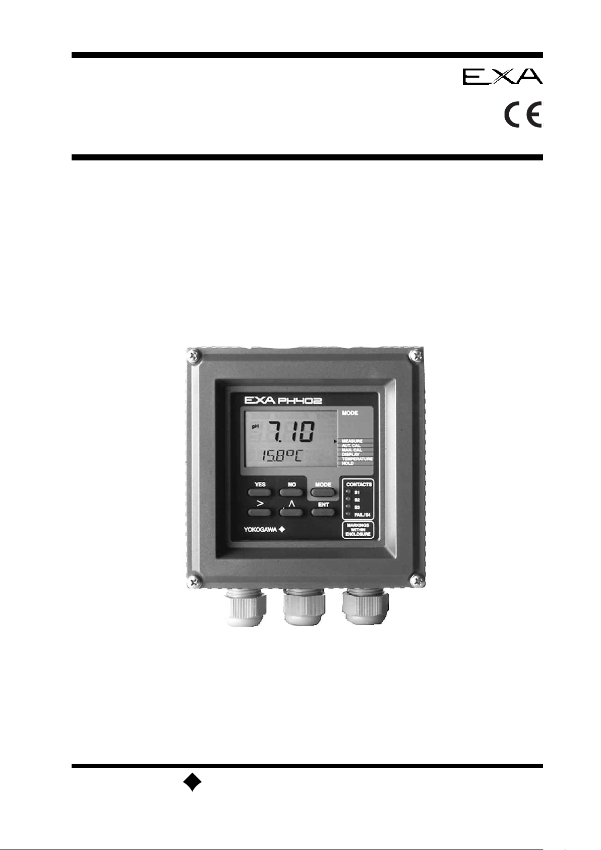
Model PH402G
pH Converter
IM 12B6B3-E-E
8th Edition
Page 2

TABLE OF CONTENTS
PREFACE
1. INTRODUCTION AND GENERAL DESCRIPTION . . . . . . . . . . . . . . . . . . . . . . . . . . . . . . . . . . . 1-1
-1. Instrument check . . . . . . . . . . . . . . . . . . . . . . . . . . . . . . . . . . . . . . . . . . . . . . . . . . . . . . . . .1-1
1
1-2. Application . . . . . . . . . . . . . . . . . . . . . . . . . . . . . . . . . . . . . . . . . . . . . . . . . . . . . . . . . .1-2
2. PH402 SPECIFICATIONS . . . . . . . . . . . . . . . . . . . . . . . . . . . . . . . . . . . . . . . . . . . . . . . . . . . . . . .2-1
-1. General . . . . . . . . . . . . . . . . . . . . . . . . . . . . . . . . . . . . . . . . . . . . . . . . . . . . . . . . . .2-1
2
2-2. Operating specifications . . . . . . . . . . . . . . . . . . . . . . . . . . . . . . . . . . . . . . . . . . . . . . . . . . . . . .2-2
2-3. Model and suffix codes . . . . . . . . . . . . . . . . . . . . . . . . . . . . . . . . . . . . . . . . . . . . . . . . . . . . . .2-2
3. INSTALLATION AND WIRING . . . . . . . . . . . . . . . . . . . . . . . . . . . . . . . . . . . . . . . . . . . . . . . . . . .3-1
3-1. Installation and dimensions . . . . . . . . . . . . . . . . . . . . . . . . . . . . . . . . . . . . . . . . . . . . . . . . . . .3-1
3-1-1. Installation site . . . . . . . . . . . . . . . . . . . . . . . . . . . . . . . . . . . . . . . . . . . . . . . . . . . . . . . . .3-1
3-1-2. Mounting methods . . . . . . . . . . . . . . . . . . . . . . . . . . . . . . . . . . . . . . . . . . . . . . . . . . . . .3-1
3-2. Preparation . . . . . . . . . . . . . . . . . . . . . . . . . . . . . . . . . . . . . . . . . . . . . . . . . . . . . . . . . .3-3
3-3. Wiring the power supply . . . . . . . . . . . . . . . . . . . . . . . . . . . . . . . . . . . . . . . . . . . . . . . . . . . . .3-4
3-3-1. General precautions . . . . . . . . . . . . . . . . . . . . . . . . . . . . . . . . . . . . . . . . . . . . . . . . . . . .3-4
3-3-2. Access to terminal and cable entry . . . . . . . . . . . . . . . . . . . . . . . . . . . . . . . . . . . . . . . . .3-4
3-3-3. AC power . . . . . . . . . . . . . . . . . . . . . . . . . . . . . . . . . . . . . . . . . . . . . . . . . . . . . . . . . .3-5
3-3-4. DC power . . . . . . . . . . . . . . . . . . . . . . . . . . . . . . . . . . . . . . . . . . . . . . . . . . . . . . . . . .3-5
3-3-5. Grounding the housing . . . . . . . . . . . . . . . . . . . . . . . . . . . . . . . . . . . . . . . . . . . . . . . . . .3-5
3-3-6. Switching on the instrument . . . . . . . . . . . . . . . . . . . . . . . . . . . . . . . . . . . . . . . . . . . . . .3-5
3-4. Wiring the contact signals . . . . . . . . . . . . . . . . . . . . . . . . . . . . . . . . . . . . . . . . . . . . . . . . . . . .3-6
3-4-1. General precautions . . . . . . . . . . . . . . . . . . . . . . . . . . . . . . . . . . . . . . . . . . . . . . . . . . . .3-6
3-4-2. Contact outputs . . . . . . . . . . . . . . . . . . . . . . . . . . . . . . . . . . . . . . . . . . . . . . . . . . . . . . .3-6
3-5. Wiring the analog output signals . . . . . . . . . . . . . . . . . . . . . . . . . . . . . . . . . . . . . . . . . . . . . . .3-6
3-5-1. General precautions . . . . . . . . . . . . . . . . . . . . . . . . . . . . . . . . . . . . . . . . . . . . . . . . . . . .3-6
3-5-2. Analog output signals . . . . . . . . . . . . . . . . . . . . . . . . . . . . . . . . . . . . . . . . . . . . . . . . . . .3-6
3-6. Wiring the sensor system . . . . . . . . . . . . . . . . . . . . . . . . . . . . . . . . . . . . . . . . . . . . . . . . . . . . .3-7
3-6-1. Impedance measurement jumper settings . . . . . . . . . . . . . . . . . . . . . . . . . . . . . . . . . . . .3-7
3-7. Sensor wiring . . . . . . . . . . . . . . . . . . . . . . . . . . . . . . . . . . . . . . . . . . . . . . . . . . . . . . . . .3-10
3-7-1. Connection cable . . . . . . . . . . . . . . . . . . . . . . . . . . . . . . . . . . . . . . . . . . . . . . . . . . . . .3-11
3-7-2. Sensor cable connection with special grommet . . . . . . . . . . . . . . . . . . . . . . . . . . . . . .3-12
3-13
3-7-3. Sensor cable connections using junction box (BA10) and extension cable (WF10)
. . . .
3-8. Tag plate mounting . . . . . . . . . . . . . . . . . . . . . . . . . . . . . . . . . . . . . . . . . . . . . . . . . . . . . . . .3-15
4.
OPERA
TION; DISPLA
Y FUNCTIONS AND SETTING
. . . . . . . . . . . . . . . . . . . . . . . . . . . . . . . . .
4-1
4-1. Operator interface . . . . . . . . . . . . . . . . . . . . . . . . . . . . . . . . . . . . . . . . . . . . . . . . . . . . . . . . . .4-1
4-2. Explanation of operating keys . . . . . . . . . . . . . . . . . . . . . . . . . . . . . . . . . . . . . . . . . . . . . . . . .4-2
4-3. Setting passcodes
. . . . . . . . . . . . . . . . . . . . . . . . . . . . . . . . . . . . . . . . . . . . . . . . . . . . . . . . . .
4-3
4-3-1. Passcode protection . . . . . . . . . . . . . . . . . . . . . . . . . . . . . . . . . . . . . . . . . . . . . . . . . . . .4-3
4-4. Display examples . . . . . . . . . . . . . . . . . . . . . . . . . . . . . . . . . . . . . . . . . . . . . . . . . . . . . . . . . .4-3
4-5. Display functions
4-5-1. Display functions pH (default) . . . . . . . . . . . . . . . . . . . . . . . . . . . . . . . . . . . . . . . . . . . . .
. . . . . . . . . . . . . . . . . . . . . . . . . . . . . . . . . . . . . . . . . . . . . . . . . . . . . . . . . .4-4
4-4
4-5-2. Display functions pH (ORP) . . . . . . . . . . . . . . . . . . . . . . . . . . . . . . . . . . . . . . . . . . . . . . .4-5
4-5-3. Display functions pH (rH) . . . . . . . . . . . . . . . . . . . . . . . . . . . . . . . . . . . . . . . . . . . . . . . . .4-6
5. PARAMETER SETTING . . . . . . . . . . . . . . . . . . . . . . . . . . . . . . . . . . . . . . . . . . . . . . . . . . . . . . . .5-1
5-1. Maintenance mode . . . . . . . . . . . . . . . . . . . . . . . . . . . . . . . . . . . . . . . . . . . . . . . . . . . . . . . . .5-2
5-1-1. Manual temperatur
e selection and adjustment . . . . . . . . . . . . . . . . . . . . . . . . . . . . . . . .5-3
5-1-2. Process temperature measuring in ORP mode . . . . . . . . . . . . . . . . . . . . . . . . . . . . . . . .5-4
5-1-3. Manual activation of HOLD . . . . . . . . . . . . . . . . . . . . . . . . . . . . . . . . . . . . . . . . . . . . . . .5-4
5-1-4. Manual wash start/stop . . . . . . . . . . . . . . . . . . . . . . . . . . . . . . . . . . . . . . . . . . . . . . . . . .5-5
IM 12B6B3-E-E
Page 3

5-1-5. Setpoint adjustment . . . . . . . . . . . . . . . . . . . . . . . . . . . . . . . . . . . . . . . . . . . . . . . . . . . .5-6
5-1-6. Manual impedance check . . . . . . . . . . . . . . . . . . . . . . . . . . . . . . . . . . . . . . . . . . . . . . . .5-7
5-2. Commissioning mode . . . . . . . . . . . . . . . . . . . . . . . . . . . . . . . . . . . . . . . . . . . . . . . . . . . . . . . . . .5-8
-2-1. Setpoints . . . . . . . . . . . . . . . . . . . . . . . . . . . . . . . . . . . . . . . . . . . . . . . . . . . . . . . . . .5-9
5
5-2-2. Range . . . . . . . . . . . . . . . . . . . . . . . . . . . . . . . . . . . . . . . . . . . . . . . . . . . . . . . . .5-11
5-2-3. Hold . . . . . . . . . . . . . . . . . . . . . . . . . . . . . . . . . . . . . . . . . . . . . . . . . . . . . . . . .5-13
5-2-4. Wash . . . . . . . . . . . . . . . . . . . . . . . . . . . . . . . . . . . . . . . . . . . . . . . . . . . . . . . . .5-15
-2-5. Service . . . . . . . . . . . . . . . . . . . . . . . . . . . . . . . . . . . . . . . . . . . . . . . . . . . . . . . . .5-16
5
-3. Notes for guidance in the use of service coded settings . . . . . . . . . . . . . . . . . . . . . . . . . . . . . . .5-17
5
5-3-1. Parameter specific functions . . . . . . . . . . . . . . . . . . . . . . . . . . . . . . . . . . . . . . . . . . . . .5-18
5-3-2. Temperature compensation and measuring functions . . . . . . . . . . . . . . . . . . . . . . . . . .5-20
5-3-3. Calibration functions . . . . . . . . . . . . . . . . . . . . . . . . . . . . . . . . . . . . . . . . . . . . . . . . . . .5-22
5-3-4. mA Output functions . . . . . . . . . . . . . . . . . . . . . . . . . . . . . . . . . . . . . . . . . . . . . . . . . . .5-24
5-3-5. Contact outputs . . . . . . . . . . . . . . . . . . . . . . . . . . . . . . . . . . . . . . . . . . . . . . . . . . . . . .5-26
5-3-6. User interface . . . . . . . . . . . . . . . . . . . . . . . . . . . . . . . . . . . . . . . . . . . . . . . . . . . . . . . .5-30
5-3-7. Communication setup . . . . . . . . . . . . . . . . . . . . . . . . . . . . . . . . . . . . . . . . . . . . . . . . . .5-32
5-3-8. General . . . . . . . . . . . . . . . . . . . . . . . . . . . . . . . . . . . . . . . . . . . . . . . . . . . . . . . . .5-32
5-3-9. Test and setup mode . . . . . . . . . . . . . . . . . . . . . . . . . . . . . . . . . . . . . . . . . . . . . . . . . .5-34
6. CALIBRATION . . . . . . . . . . . . . . . . . . . . . . . . . . . . . . . . . . . . . . . . . . . . . . . . . . . . . . . . . .6-1
6-1. Automatic calibration . . . . . . . . . . . . . . . . . . . . . . . . . . . . . . . . . . . . . . . . . . . . . . . . . . . . . . . .6-1
6-2. Manual calibration
. . . . . . . . . . . . . . . . . . . . . . . . . . . . . . . . . . . . . . . . . . . . . . . . . . . . . . . . . .6-1
6-3. Sample calibration . . . . . . . . . . . . . . . . . . . . . . . . . . . . . . . . . . . . . . . . . . . . . . . . . . . . . . . . . .6-1
6-4. Data entry . . . . . . . . . . . . . . . . . . . . . . . . . . . . . . . . . . . . . . . . . . . . . . . . . . . . . . . . . .6-1
6-5. Calibration procedures . . . . . . . . . . . . . . . . . . . . . . . . . . . . . . . . . . . . . . . . . . . . . . . . . . . . . . .6-2
6-5-1. Automatic calibration . . . . . . . . . . . . . . . . . . . . . . . . . . . . . . . . . . . . . . . . . . . . . . . . . . . .6-2
6-5-2. Automatic calibration with HOLD active . . . . . . . . . . . . . . . . . . . . . . . . . . . . . . . . . . . . . .6-3
6-5-3. Manual calibration (2nd parameter calibration) . . . . . . . . . . . . . . . . . . . . . . . . . . . . . . . . .6-4
6-5-4. Sample calibration . . . . . . . . . . . . . . . . . . . . . . . . . . . . . . . . . . . . . . . . . . . . . . . . . . . . . .6-6
7. MAINTENANCE . . . . . . . . . . . . . . . . . . . . . . . . . . . . . . . . . . . . . . . . . . . . . . . . . . . . . . . . . .7-1
7-1. Periodic maintenance for the EXA PH402 converter . . . . . . . . . . . . . . . . . . . . . . . . . . . . . . . .7-1
7-2. Periodic maintenance for the sensor system . . . . . . . . . . . . . . . . . . . . . . . . . . . . . . . . . . . . . .7-1
8. TROUBLESHOOTING . . . . . . . . . . . . . . . . . . . . . . . . . . . . . . . . . . . . . . . . . . . . . . . . . . . . . . . . . .8-1
8-1. Diagnostics . . . . . . . . . . . . . . . . . . . . . . . . . . . . . . . . . . . . . . . . . . . . . . . . . . . . . . . . . .8-2
8-1-1. Off-line calibration checks . . . . . . . . . . . . . . . . . . . . . . . . . . . . . . . . . . . . . . . . . . . . . . . .8-2
8-1-2. On-line impedance checks . . . . . . . . . . . . . . . . . . . . . . . . . . . . . . . . . . . . . . . . . . . . . . .8-2
9. SPARE PARTS . . . . . . . . . . . . . . . . . . . . . . . . . . . . . . . . . . . . . . . . . . . . . . . . . . . . . . . . . .9-1
10. APPENDIX . . . . . . . . . . . . . . . . . . . . . . . . . . . . . . . . . . . . . . . . . . . . . . . . . . . . . . . . .10-1
10-1. User setting table . . . . . . . . . . . . . . . . . . . . . . . . . . . . . . . . . . . . . . . . . . . . . . . . . . . . . . . . .10-1
10-2. Configuration checklist for PH402G . . . . . . . . . . . . . . . . . . . . . . . . . . . . . . . . . . . . . . . . . . .10-3
10-3. Setup for sensor compatibility . . . . . . . . . . . . . . . . . . . . . . . . . . . . . . . . . . . . . . . . . . . . . . .10-4
10-3-1. General
. . . . . . . . . . . . . . . . . . . . . . . . . . . . . . . . . . . . . . . . . . . . . . . . . . . . . . . . .
10-4
10-3-2. Selection of measurement and reference electrode . . . . . . . . . . . . . . . . . . . . . . . . . . .10-4
10-3-3. Selecting a temperature sensor . . . . . . . . . . . . . . . . . . . . . . . . . . . . . . . . . . . . . . . . . .10-4
10-4. Setup for other functions
. . . . . . . . . . . . . . . . . . . . . . . . . . . . . . . . . . . . . . . . . . . . . . . . . . .
10-5
10-5. Set up for Pfaudler Type 18 sensor . . . . . . . . . . . . . . . . . . . . . . . . . . . . . . . . . . . . . . . . . . .10-6
10-5-1. General set up . . . . . . . . . . . . . . . . . . . . . . . . . . . . . . . . . . . . . . . . . . . . . . . . . . . . . . .10-6
10-5-2. Calibration set up
10-6. Softwar
GLOSSAR
e histor
Y
. . . . . . . . . . . . . . . . . . . . . . . . . . . . . . . . . . . . . . . . . . . . . . . . . . . .
. . . . . . . . . . . . . . . . . . . . . . . . . . . . . . . . . . . . . . . . . . . . . . . . . . . . . . . . .
y
10-6
10-7
ERROR CODES
QUALITY INSPECTION STANDARD & CERTIFICATE
IM 12B6B3-E-E
Page 4

CAUTION
PREFACE
WARNING
Electric discharge
The EXA analyzer contains devices that can be damaged by electrostatic discharge. When servicing this
equipment, please observe proper procedures to prevent such damage. Replacement components should
be shipped in conductive packaging. Repair work should be done at grounded workstations using
rounded soldering irons and wrist straps to avoid electrostatic discharge.
g
Installation and wiring
The EXA analyzer should only be used with equipment that meets the relevant IEC, American or Canadian
standards. Yokogawa accepts no responsibility for the misuse of this unit.
The Instr
ument is packed carefully with shock absorbing materials, nevertheless, the instrument may be
damaged or broken if subjected to strong shock, such as if the instrument is dropped. Handle with care.
Although the instr
ument has a weatherproof construction, the transmitter can be harmed if it becomes
submerged in water or becomes excessively wet.
Do not use an abrasive or solvent in cleaning the instrument.
Notice
Contents of this manual are subject to change without notice. Yokogawa is not responsible for damage to
the instrument, poor performance of the instrument or losses resulting from such, if the problems are
caused by:
l Improper operation by the user.
l Use of the instrument in improper applications
l Use of the instrument in an improper environment or improper utility program
l Repair or modification of the related instrument by an engineer not authorized by Yokogawa.
Warranty and service
Yokogawa products and parts are guaranteed free from defects in workmanship and material under normal
use and service for a period of (typically) 12 months fr
om the date of shipment from the manufactur
er.
Individual sales organisations can deviate from the typical warranty period, and the conditions of sale
elating to the original purchase order should be consulted. Damage caused by wear and tear, inadequate
r
maintenance, cor
osion, or by the ef
r
fects of chemical pr
ocesses ar
e excluded fr
om this war
ranty coverage.
In the event of warranty claim, the defective goods should be sent (freight paid) to the service department of
elevant sales or
the r
ganisation for r
epair or r
eplacement (at Y
okogawa discr
etion). The following information
must be included in the letter accompanying the returned goods:
l Part number
l Original pur
l Length of time in service and a description of the process
l Description of the fault, and the cir
ocess/envir
l Pr
l A statement whether warranty or non-warranty service is requested
l Complete shipping and billing instructions for return of material, plus the name and phone number of a
contact person who can be r
ned goods that have been in contact with process fluids must be decontaminated/disinfected before
Retur
shipment. Goods should car
, model code and serial number
chase or
der and date
cumstances of failur
onmental conditions that may be r
eached for further information.
tificate to this ef
y a cer
r
e
elated to the installation failur
e of the device
fect, for the health and safety of our employees. Material
safety data sheets should also be included for all components of the processes to which the equipment has
been exposed.
IM 12B6B3-E-E
Page 5
Introduction 1-1
MODEL
SERIAL NO.
SUPPLY
PH402G-E-1-E
FD 020 034
110-120 VAC, 50/60 Hz, 10 VA
N200
1. INTRODUCTION AND GENERAL DESCRIPTION
The Yokogawa EXA 402 is a 4-wire transmitter designed for industrial process monitoring, measurement
and control applications. This instruction manual contains the information needed to install, set up, operate
and maintain the unit correctly. This manual also includes a basic troubleshooting guide to answer typical
user questions.
Yokogawa can not be responsible for the performance of the EXA analyzer if these instructions are not
followed.
1-1. Instrument Check
Upon delivery, unpack the instrument carefully and inspect it to ensure that it was not damaged during
shipment. If damage is found, retain the original packing materials (including the outer box) and then
immediately notify the carrier and the relevant Yokogawa sales office.
Make sure the model number on the nameplate affixed to the top of the display board of the instrument
agrees with your order.
NOTE:
The nameplate will also contain the serial number and power supply selection.
Be sure to apply correct power to the unit.
Figure 1-1. Nameplate
Check that all the parts are present, including mounting hardware, as specified in the option codes at the
end of the model number. For a description of the model codes, refer to Chapter 2 of this manual under
General Specifications.
Basic Parts List: Converter EXA 402
Instruction Manual (See model code for language)
Packet with special cable gr
ommet and blanking pieces
Packet with 4 screws for mounting on a panel (M6x8mm)
Optional mounting hardware when specified (See model code)
IM 12B6B3-E-E
Page 6

1-2 Introduction
1-2. Application
he EXA converter is intended to be used for continuous on-line measurement in industrial installations. The
T
unit combines simple operation and microprocessor-based performance with advanced self-diagnostics and
enhanced communications capability to meet the most advanced requirements. The measurement can be
used as part of an automated process control system. It can also be used to indicate dangerous limits of a
process, to monitor product quality, or to function as a simple controller for a dosing/neutralisation system.
Yokogawa designed the EXA analyzer to withstand harsh environments. The converter may be installed
either indoors or outside because the IP65 (NEMA4X) housing and cabling glands ensure the unit is
adequately protected. The flexible polycarbonate window on the front door of the EXA allows pushbutton
access to the keypad, thus preserving the water and dust protection of the unit even during routine
maintenance operations.
A variety of EXA hardware is optionally available to allow wall, pipe, or panel mounting. Selecting a proper
installation site will permit ease of operation. Sensors should normally be mounted close to the converter in
order to ensure easy calibration and peak performance. If the unit must be mounted remotely from the
sensors, WF10 extension cable can be used up to a maximum of 50 metres (150 feet) with a BA10 junction
box. Except installations with dual high impedance sensors, where the maximum cable length is 20
metres using integral cable only (no junction box).
The EXA is delivered with a general purpose default setting for programmable items. (Default settings are
listed in Chapter 5 and again in Chapter 10). While this initial configuration allows easy start-up, the
configuration should be adjusted to suit each par
ticular application. An example of an adjustable item is the
type of temperature sensor used. The EXA can be adjusted for any one of five different types of temperature
sensors.
To record such configuration adjustments, write changes in the space provided in Chapter 10 of this
manual. Because the EXA is suitable for use as a monitor, a controller or an alarm instrument, program
configuration possibilities are numerous.
Details provided in this instruction manual are sufficient to operate the EXA with all Yokogawa sensor
systems and a wide range of third-party commercially available probes. For best results, read this manual in
conjunction with the corresponding sensor instruction manual.
Yokogawa designed and built the EXA to meet the CE regulatory standards. The unit meets or exceeds
stringent requirements of EN 55082-2, EN55022 Class A and low voltage safety directive IEC1010 without
mance in even the most demanding industrial
omise, to assur
compr
e the user of continued accurate per
for
installations.
IM 12B6B3-E-E
Page 7

Specification 2-1
2. PH402 SPECIFICATIONS
-1. General
2
A. Input specifications
: Dual high impedance inputs
(2 x 10¹³Ω) with provision for
liquid earth connection.
uitable for inputs from glass
S
or enamel pH & reference
sensors and ORP metal
electrodes.
B. Input ranges
- pH : -2 to 16 pH
- ORP : -1500 to 1500 mV
- rH : 0 to 55 rH
- Temperature : -30 to 140 ºC
(-20 -to 300 ºF)
(for 8k55 sensor -10 to
120 ºC (10 to 250 ºF);
for 10kPTC sensor -20 to
140 ºC (0 to 300 ºF))
C. Span
- pH : min 1 max 20 pH
- ORP : min 100 max 2000 mV
- rH : min 2 max 55 rH
- Temperature : min 25 ºC max 200 0C
min 50 ºF max 400 0F
(for 8k55 sensor max 100 ºC
(250 ºF))
D. Transmission Signals
: Two isolated outputs of 0/4-
20 mA DC with common
negative.
Maximum load 600 Ω.
Auxiliary output can be
chosen from pH, temperature,
ORP or rH (with suitable
sensor), P.I. control. burn up
(22 mA) or burn down
(0/3.5 mA) to signal failure.
E. Temperature compensation
- Range : Automatic or manual
compensation to Nernst
equation.
Process compensation by
configurable temperature
coefficient.
Adjustable ITP (Isothermal
point of intersection).
F. Calibration : Semi-automatic using
preconfigured NIST buffer
tables 4, 7 & 9, or with user
defined buffer tables, with
automatic stability check.
anual adjustment to grab
M
sample.
Slope and Asymmetry
Potential setting.
Zero point can be selected for
alibration and display instead
c
of As. Pot. (IEC746-2)
G. Serial Communication
: Bi-directional according to the
EIA-485 standard using HART
protocol and PC402 software.
H. Logbook : Software record of important
events and diagnostic data.
Available through RS485, with
key diagnostic information
available in the display.
I. Display : Custom liquid crystal display,
1
2
with a main display of 3
/
digits 12.5 mm high. Message
display of 6 alphanumeric
characters, 7 mm high.
Warning flags and units (pH
and mV) as appropriate.
J. Contact outputs
- General : Four (4) SPDT relay contacts
with LED indicators. For S1,
S2, and S3, the LED is on
when relay is powered.
NOTE: For S4 (FAIL) LED
lights when power is
removed (Fail safe).
Contact outputs configurable
for hysteresis and delay time.
- Switch capacity : Maximum values 100 VA,
250 VAC, 5 Amps.
Maximum values 50 Watts,
250 VDC, 5 Amps.
- Status : High/Low process alarms,
selected from pH, ORP, rH
and temperature.
Contact output is also
available to signal “Hold
Active”
- Control function : On / Off
PI pulsed Proportional duty cycle
control with integral term.
PI frequency Proportional frequency control
with integral term. In addition
wash cleaning control signal on
S3, and FAIL alarm for system
and diagnostic errors on S4
IM 12B6B3-E-E
Page 8

2-2 Specifications
K. Contact input : Remote wash cycle start.
L. Power supply : 230 VAC ±15%, 50/60 Hz.
Max. consumption 10 VA.
115 VAC ±15%, 50/60 Hz.
Max. consumption 10 VA.
00 VAC ± 15% 50/60 Hz.
1
Max. consumption 10 VA.
24 VDC -20% / +30%
Max. consumption 10 Watts.
M. Input isolation : 1000 VDC
N. Shipping details: Package size w x h x d
290 x 225 x 170 mm.
11.5 x 8.9 x 6.7 in.
Packed weight approx.
2.5 kg (5lb).
2-2. Operating specifications
A. Performance : pH
- Linearity : ≤0.01 pH ± 0.02 mA
- Repeatability : ≤0.01 pH ± 0.02 mA
- Accuracy : ≤0.01 pH ± 0.02 mA
Performance : ORP
- Linearity : ≤1 mV ± 0.02 mA
- Repeatability : ≤1 mV ± 0.02 mA
- Accuracy : ≤1 mV ± 0.02 mA
Performance : Temperature with Pt1000
Ω, 3 kΩ Balco, 5 k1Ω and
10k PTC
- Linearity : ≤0.2 oC ± 0.02 mA
- Repeatability : ≤0.1 oC ± 0.02 mA
- Accuracy : ≤0.3 oC ± 0.02mA
Performance : Temperature with Pt100 Ω
& 8k55
Ω
- Linearity : ≤0.3 oC ± 0.02 mA
- Repeatability : ≤0.1 oC ± 0.02 mA
- Accuracy
: ≤0.4
± 0.02 mA
C
o
B. Ambient operating temperature
-30 to +70
:
o
C (-20 to 160 ºF)
for mA output.
-10 to +70 oC (10 to 160 ºF)
for LCD
C. Storage temperature
: -30 to +70 oC (-20 to 160 ºF)
D. Humidity : 10 to 90% RH non-
condensing
E. Housing
Case : Cast aluminium with
chemically resistant coating
Cover : flexible polycarbonate window.
ase color : off-white and
C
Cover color : moss green.
Cable entry : via six 1/2” polyamide glands.
Cable terminals : are provided for up to 2.5
mm2finished wires.
rotection : weather resistant to IP65 and
P
NEMA 4X standards.
Mounting : Pipe wall or panel, using
optional hardware.
F. Data protection : EEPROM for configuration and
logbook, and lithium battery
for clock.
G. Watchdog timer: Checks microprocessor
H. Automatic safeguard
: Return to measuring mode
when no keystroke is made
for 10 min.
I. Power interruption
: Less than 50 milliseconds no
effect. More than 50
milliseconds reset to
measurement.
J. Operation protection
: 3-digit programmable
password.
K. Regulatory compliance
- EMC : meets council directive
89/336/EEC
- Emmission : meets EN 55022 Class A
- Immunity
: meets EN 50082-2
- Low voltage : meets council directive
73/23/EEC
- Installation
: Designed for installation
conforming to IEC 1010-1.
Category II.
2-3. Model and suffix codes
Model Suffix Option Description
PH402G .................................... pH/ORP transmitter
Supply -1 ........................... 115 Volts 50/60 Hz
voltage
Instr
Options /U......... Pipe and wall mounting
* For other languages contact local sales of
-E ................................ Always E
...........................
-2
-4........................... 24 Volts DC
-5
uction manual -E
........................... 100 Volts 50/60 Hz
code
olts 50/60 Hz
230 V
.................... English language *
e
dwar
/PM...... Panel mounting hardware
/Q
/SCT
har
........ Quality certificate
Stainless steel tag
....
fice
IM 12B6B3-E-E
Page 9
Installation and wiring 3-1
min.185 (7.25)
min.195 (7.75)
1
3
8 (5.
43)
138
M6
M6
M5
cut - out = 138 x 138 (5.43 x 5.43)
3. INSTALLATION AND WIRING
3-1. Installation and dimensions
-1-1. Installation site
3
The EXA converter is weatherproof and can be installed inside or outside. It should, however, be installed as
lose as possible to the sensor to avoid long cable runs between sensor and converter. In any case, the
c
cable length should not exceed 50 meters (162 feet). Select an installation site where:
l Mechanical vibrations and shocks are negligible
l No relay/power switches are in the direct environment
l Access is possible to the cable glands (see figure 3-1)
l The transmitter is not mounted in direct sunlight or severe weather conditions
l Maintenance procedures are possible (avoiding corrosive environments)
The ambient temperature and humidity of the installation environment must be within the limits of the
instrument specifications. (See chapter 2).
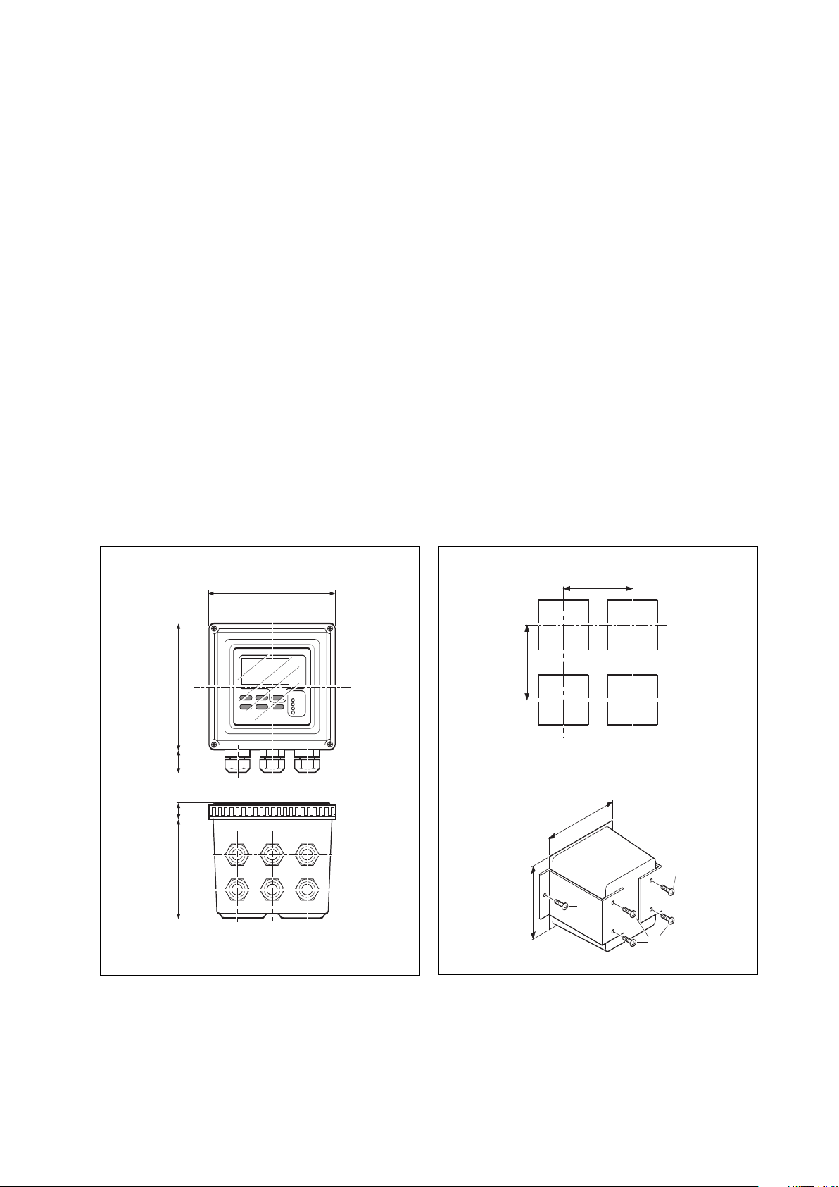
3-1-2. Mounting methods
Refer to figures 3-2 and 3-3. Note that the EXA converter has universal mounting capabilities:
l Panel mounting using optional brackets
l Surface mounting on a plate (using bolts from the back)
l Wall mounting on a bracket (for example, on a solid wall)
l Pipe mounting using a bracket on a horizontal or vertical pipe (maximum pipe diameter 50 mm)
144(5.67)
24(1)
16.5
(0.65)
115.5(4.55)
Figure 3-1. Housing dimensions and layout of
glands
144(5.67)
Figure 3-2. Panel mounting diagram
IM 12B6B3-E-E
Page 10
3-2 Installation and wiring
wall mounting pipe mounting
80
(3.15)
2x ø6.5
(0.26)
200
(7.87)
70
(2.75)
4x ø10
(0.4)
145
(5.70)
Figure 3-3. Wall and pipe mounting diagram
pipe mounting
(vertical)
(horizontal)
2” ND. pipe
OPTION/U: Universal pipe/wall mounting kit
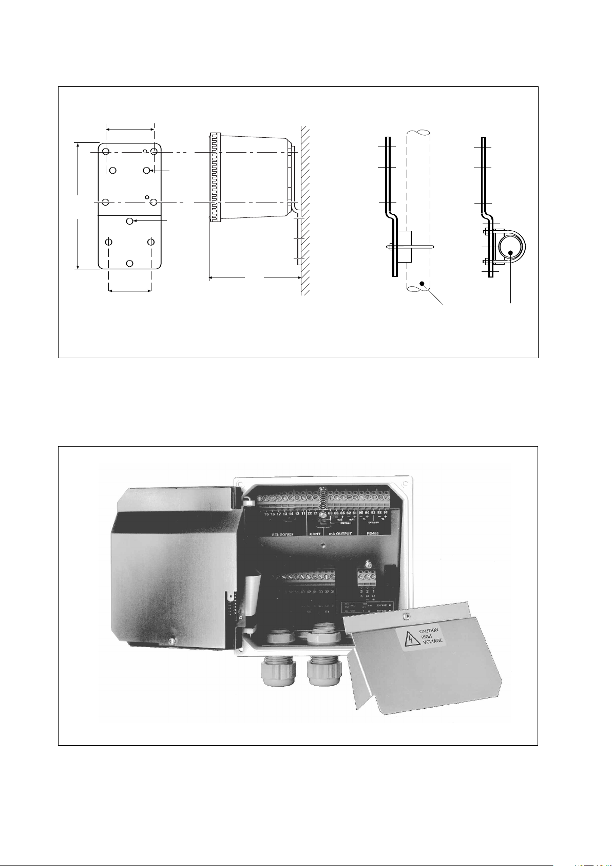
e 3-4. Internal view of EXA wiring compartment
Figur
IM 12B6B3-E-E
Page 11
Installation and wiring 3-3
12D7C3-04
GLANDS TO BE
USED FOR CABLING
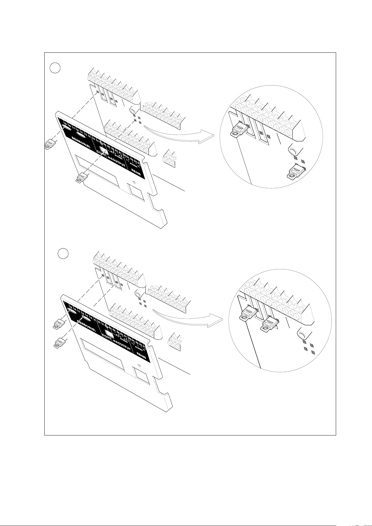
3-2. Preparation
efer to figure 3-4. The relay contact terminals and power supply connections are under the screening
R
(shielding) plate. These should be connected first. Connect the sensor, outputs and data communication
connections last.
To open the EXA 402 for wiring:
. Loosen the four frontplate screws and remove the cover.
1
2. Use the rubber knob in the lower righthand corner and swing open the display board to the left.
3. The upper terminal strip is now visible.
4. Remove the screen (shield) plate covering the lower terminal strip.
5. Connect the power supply and contact outputs. Use the three glands at the back for these cables.
6. Replace the screen (shield) plate over the lower terminals.
WARNING
Always replace the screen plate over the power and contact outputs for safety and avoid
interference.
7. Connect the analog output(s), the sensor input, and, if necessary, the RS485 serial bus.
8. Use the front three glands for analog output, sensor input, contact input and communication cabling
(see figur
e 3-5).
9. Close the display board and switch on the power. Commission the instrument as required or use the
default settings.
Replace the cover and secure frontplate with the four screws.
10.
High voltage section
Contact
(S3,S4,FAIL)
output
cables
Sensor
cables
Contact
(S1,S2)
output
cables
Analog
output
cables
Power
cable
Communi-
cation,
contact
input
Suitable for cables with an outside diameter between 7 - 12 mm (9/32-15/32in.)
Figure 3-5. Glands to be used for cabling
IM 12B6B3-E-E
Page 12
3-4 Installation and wiring
S1
S2
S4/FAIL
S3/WASH
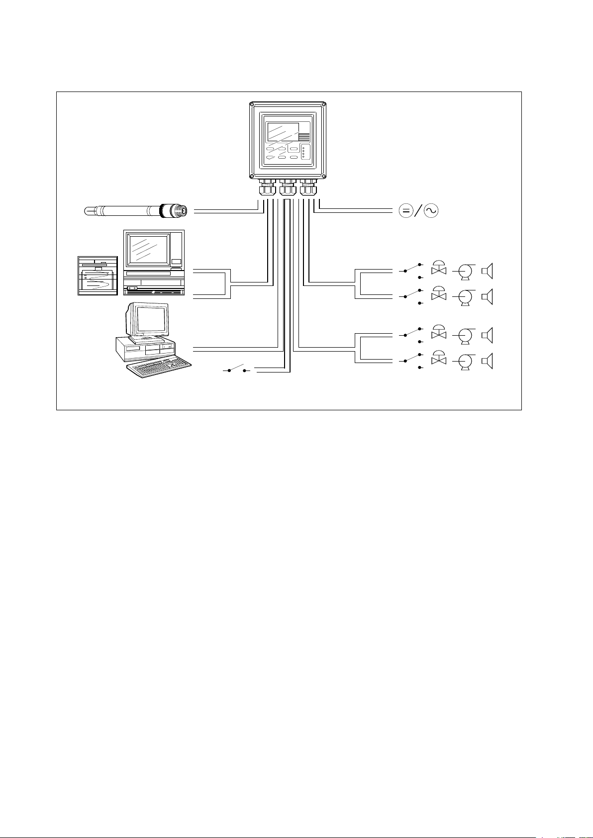
SYSTEM CONFIGURATION
1
SYSTEM CONFIGURATION
FRONT GLANDS
0/4-20 mA
0/4-20 mA
Figure 3-6. System configuration
Sensor
Output
signals
RS485
Contact input
REAR GLANDS
Power
Contact
output
ontact
C
output
3-3. Wiring the power supply
3-3-1. General pr
ecautions
Make sure the power supply is switched off. Also, make sure that the power supply is correct for the
specifications of the EXA and that the supply agrees with the voltage specified on the nameplate. Remove
the front cover by unscrewing the four screws to check this nameplate on the top of the display board.
Local health and safety r
protected internally by a fuse. The fuse rating is dependent on the supply to the instrument. The 250 VAC
fuses should be of the “time-lag” type, conforming to IEC127.
Fuse ratings are 230 VAC - 50 mA; 100 VAC - 100 mA; 115 VAC - 100 mA; 24 VDC - 1.0 A.
The inter
nal fuse is located next to the power ter
3-3-2. Access to terminal and cable entry
Terminals 1, 2 and 3 on the bottom terminal strip are used for the power supply. Guide the power cables
through the gland closest to the power supply terminals. The terminals will accept wires of 2.5 mm2(14
AWG). Use cable finishings if possible.
Connect the wires as indicated in the wiring diagram (refer to figure 3-6).
egulations may r
e an external circuit breaker to be installed. The instrument is
equir
minals (in the lower righthand corner).
IM 12B6B3-E-E
Page 13
Installation and wiring 3-5
1
41317
1
1
1
2 22 21 63 66 65 62 61 95 94 93 9291
SCREEN
mA2
mA1
SCREEN
TL TL
161
5
7
1
S4
S3
S2
S1
C NC N
O
7
2 73 51 52 53 41 43 31 334232
250V AC
5A
100V A
2
50VDC
5A
50W
F
USE
1
00
115
2
30
24
250VAC; T
3
12
C NC NO C NC NO C NC NO
V
AC
VAC
V
AC
VDC
100 mA
100 mA
50 mA
1 A
S
ensor Inputs
Contact
Input
m
A Outputs
Digital
Communications
Relay Contacts
P
ower Supply
p
H/ORP
ref.
l
iquid
earth
t
emp.
sens.
High voltage compartment
S
ENSOR(S) CONT mA OUTPUT RS485
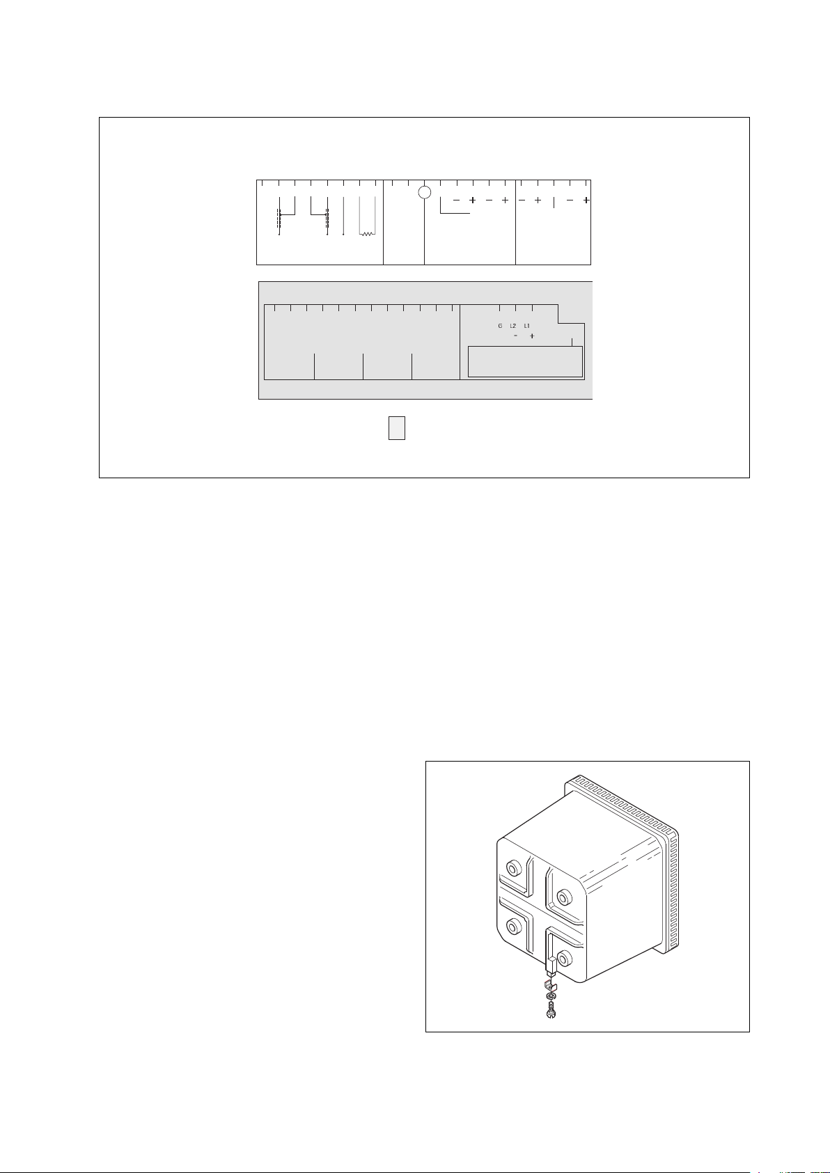
Figure 3-7. Input and output connections
3-3-3. AC power
Connect terminal 1 to the phase line of the AC power and terminal 2 to the zero line. Terminal 3 is for the
power ground. This is separated from input ground by a galvanic isolation.
3-3-4. DC power
Connect terminal 1 to the positive outlet and terminal 2 to the negative outlet. Terminal 3 is for the power
ground. This is separated from input ground by a galvanic isolation. A 2-core screened cable should be
used with the screen connected to terminal 3. The size of conductors should be at least 1.25 mm2. The
overall cable diameter should be between 7 & 12 mm.
3-3-5. Grounding the housing
ea
otect the instrument against inter
o pr
T
ence, the housing should be connected to gr
fer
ound by a lar
ge ar
conductor. This cable can be fixed to the rear of the housing using a braided wire cable. See figure 3-8.
3-3-6. Switching on the instrument
After all connections ar
e made and checked, the
power can be switched on from the power supply.
Make sure the LCD display comes on. All segments
will illuminate, then the instr
ument will momentarily
display its unique serial number. After a brief interval,
the display will change to the measured value. If
e displayed or a valid measured value is not
ors ar
r
er
shown, consult the troubleshooting section (Chapter
8) before calling Yokogawa.
Figure 3-8. Grounding the housing
IM 12B6B3-E-E
Page 14

3-6 Installation and wiring
3-4. Wiring the contact signals
3-4-1. General precautions
The contact output signals consist of voltage-free relay contacts for switching electrical appliances (SPDT).
They can also be used as digital outputs to signal processing equipment (such as a controller or PLC). It is
possible to use multi-core cables for the contact in and output signals and shielded multi-core cable for the
nalog signals.
a
3-4-2. Contact outputs
The EXA unit’s four contact outputs can be wired to suit your own custom requirements (Figure 3-6).
In the Non-Alarm or Power Off states, contacts S1, S2 and S3 are OFF, Common (C) and Normally Closed
(NC) are in contact.
In the “Fail” or Power Off states, contact S4 is ON, Common (C) and Normally Closed (NC) are in contact.
You can either use them to switch AC power, or switch a DC Voltage for digital interfacing.
Default settings
l The contact S1 is pre-programmed for high alarm function.
l The contact S2 is pre-programmed for a low alarm function.
l The contact S3 is not activated as an alarm (off).
l The contact S4 is pre-programmed for FAIL.
The three control contacts (S1 to S3) can be used for simple process control by programming their function
(Chapter 5). The FAIL contact is programmed to signal a fault in the measuring loop. Always connect the
FAIL contact to an alarm device such as a warning light, sound annunciator, or alarm panel to make full use
of the fault detection possibilities (self diagnostics) of the EXA converter.
3-5. Wiring the analog output signals
3-5-1. General precautions
The analog output signals of the EXA transmit low power standard industry signals to peripherals like control
systems or strip-chart recorders (Figure 3-6).
3-5-2. Analog output signals
The output signals consist of active current signals of either 0-20 mA or 4-20 mA. The maximum load can
be 600 ohms on each.
It is necessary to use screening/shielding on the output signal cables. Terminal 63 is used to connect the
shielding.
IM 12B6B3-E-E
Page 15

Installation and wiring 3-7
3-6. Wiring the sensor system
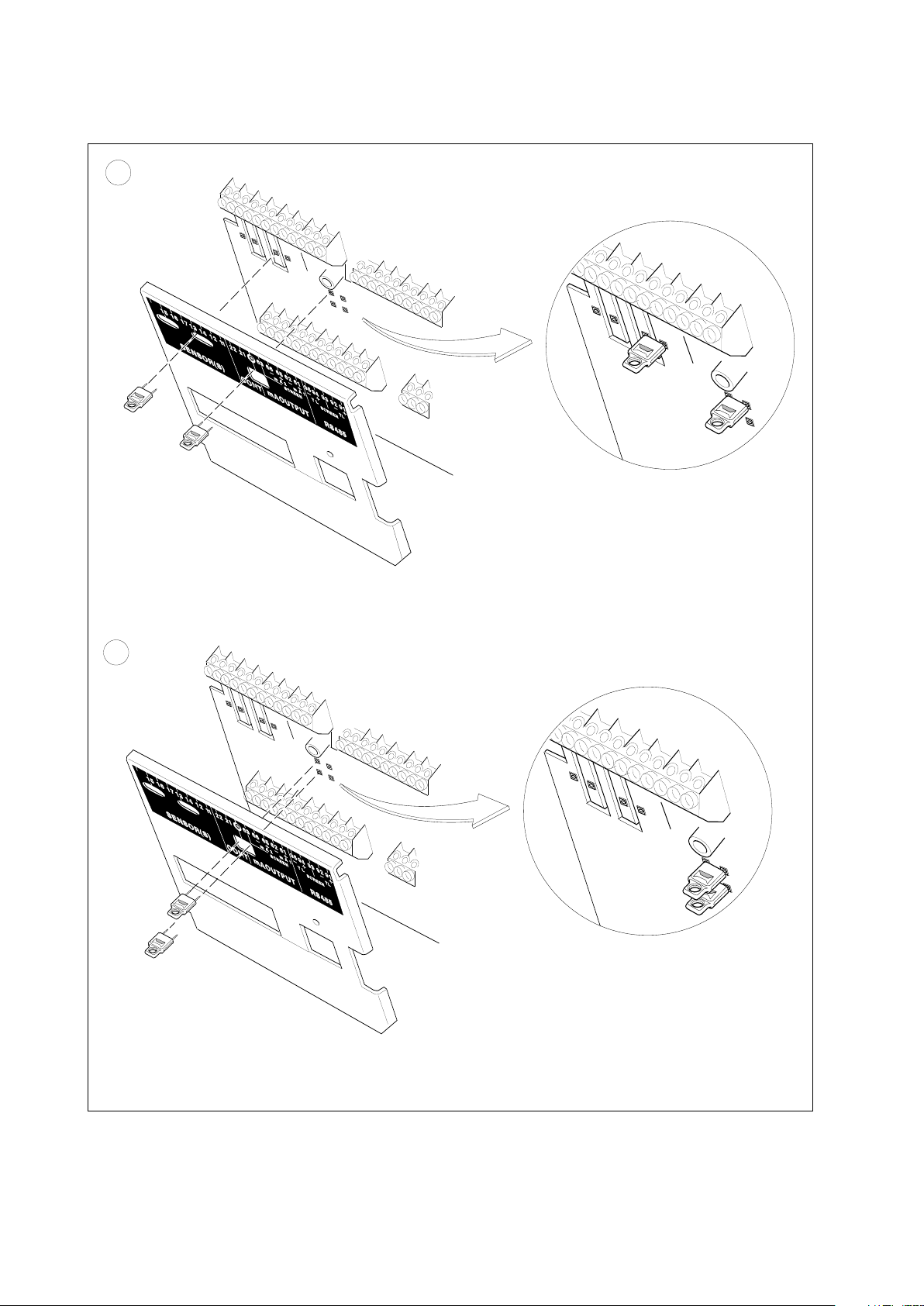
3-6-1. Impedance measurement jumper settings
NOTE:
It is important to decide first which application and which settings are appropriate for the installation. This
decision is best done before the jumpers are installed, because the cables will rest on top of the jumpers in
their installed positions.
able 3-1. Impedance measuring jumpers
T
Figure no. Jumper Settings Jumper Settings Application & Sensor Connections
Input #1 Input #2
1 High Impedance Low Impedance Normal pH sensors
Glass sensor on Input #1
Reference sensor on Input #2
2 High Impedance High Impedance Special electrodes using
2 glass sensors
(e.g. Pfaudler 18)
3 Low Impedance High Impedance ORP (pH compensated) and/or rH
metal sensor on Input #1
pH glass (as reference) on Input #2
4 Low Impedance Low Impedance ORP (Redox measurement)
metal sensor on Input #1
Normal reference on Input #2
The following four jumper figure illustrations (figure 3-9) show the jumper positions related to the figure
numbers in the above table.
IM 12B6B3-E-E
Page 16
3-8 Installation wiring
2
1
1
2D8B2-02
J
UMPERS 1&2
Default jumper connections for :
- Input 1, High impedance
- Input 2, Low impedance
Service code 03 = 1.1.1
- Input 1, High impedance, Temp. comp., Check on
Service code 04 = 0.0.1
- Input 2, Low impedance, Temp. comp. off, Check on
Jumper connections for :
- Input 1, High impedance
- Input 2, High impedance
Service code 03 = 1.0.1
- Input 1, High impedance, Temp. comp. off, Check on
vice code 04 = 1.0.1
Figure 3-9a. Impedance measurement jumper setting
IM 12B6B3-E-E
Ser
- Input 2, Low impedance, T
emp. comp. of
f, Check on
Page 17
Installation and wiring 3-9
4
3
Jumper connections for :
- Input 1, Low impedance
- Input 2, High impedance
Service code 03 = 0.0.1
- Input 1, Low impedance, Temp. comp. off, Check on
Service code 04 = 1.1.1
- Input 2, High impedance, Temp. comp. on, Check on
Jumper connections for :
- Input 1, Low impedance
- Input 2, Low impedance
vice code 03 = 0.0.1
Ser
- Input 1, Low impedance, Temp. comp. off, Check on
Figure 3-9b. Impedance measurement jumper setting
Service code 04 = 0.0.1
- Input 2, Low impedance, T
emp. comp. of
f, Check on
IM 12B6B3-E-E
Page 18

3-10 Installation and wiring
71
S4
S3
S2
S1
C NC NO
72 73 51 52 53 41 43 31 334232
250V AC
5A
100V A
250VDC
5A
50W
100
115
230
24
250VAC; T
312
C NC NO C NC NO C NC NO
VAC
VAC
VAC
V
DC
100 mA
100 mA
50 mA
1 A
SCREEN
mA2
mA1 TL
RS485
15 16 17 13
1
4
12
11 22 21 63 66 65
6
2
61
9
5
94 93 92 91
SCREEN
TL
INPUT 1
L
OW IMP
INPUT 2
L
OW IMP
I
NPUT 2
H
IGH IMP
INPUT 1
H
IGH IMP
Sensor inputs
Sensor(s)
Contact
input
Cont
mA
outputs
mA output
Relay contacts Power supply
e 3-10. Terminal identification labels
Figur
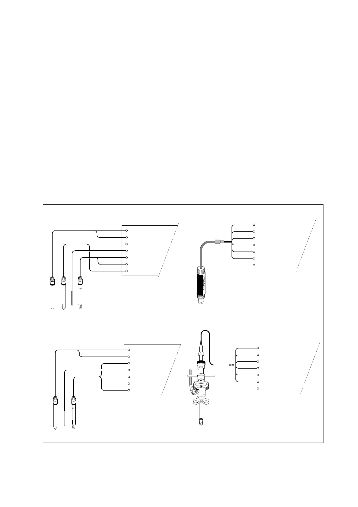
3-7. Sensor wiring
Refer to figure 3-11, which includes drawings that outline sensor wiring.
Digital
communications
Fuse
The EXA PH402 can be used with a wide range of commercially available sensor types, both from
Yokogawa and other manufacturers. The sensor systems from Yokogawa fall into two categories; the ones
that use a fixed cable and the ones with separate cables.
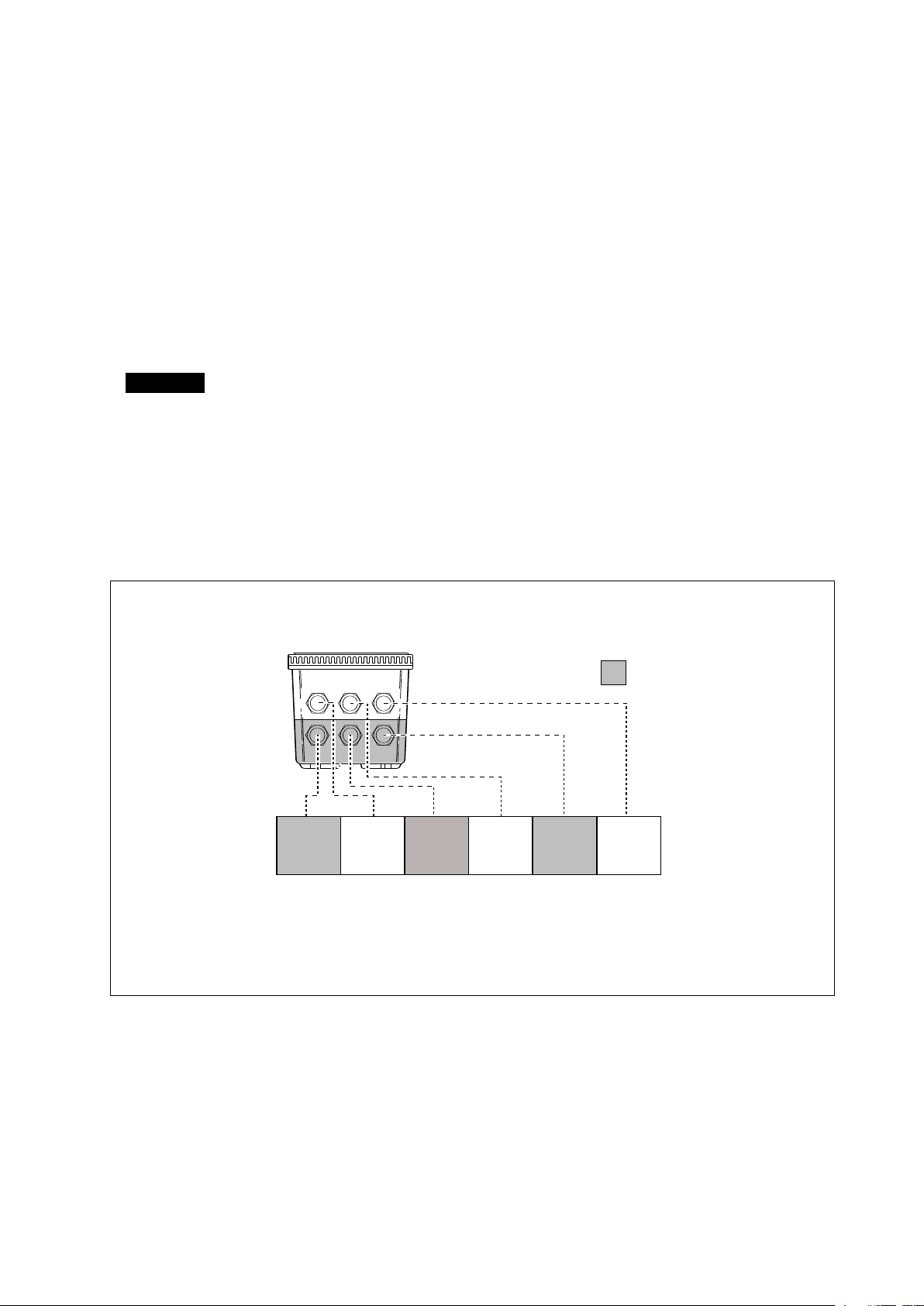
To connect sensors with fixed cables, simply match the terminal numbers in the instrument with the
identification numbers in the instrument on the cable ends.
The separate sensors and cables are not numbered, but instead use a color-coding system. The electrodes
have a colored band incorporated in the label on the connection cap:
l Red for measuring electrodes (both pH and ORP)
l Yellow for reference electrodes
l Blue for combined sensors with both measuring and reference elements in the same body
l Green for temperature sensors
The recommended procedure is to color-code each end of the cables to match the sensors with the color
strips provided with each cable. This provides a quick way to identify the ends of the cables belonging to a
particular sensor when they are installed. (The procedure for fixing the identification labels is described in
detail in the instruction sheet provided with the cable.)
IM 12B6B3-E-E
Page 19
Installation and wiring 3-11
*
*
*
*
1
2B6B3-03/1
12B6B3-03/3
*
*
*
12B6B3-03/2
3-7-1. Connection cable
here are two types of connection cable, one for single sensors and one for combined sensors. The former
T
is a coaxial cable and has only two connections.
l Red to measuring element
l Blue to screen (shield)
he latter is a triaxial cable with three connections, (it has an extra white wire termination) these wires are
T
connected:
l Red to measuring element
l Blue to reference
l White to screen (shield)
To connect the other sensor systems, follow the general pattern of the terminal connections as listed below:
11 & 12 Temperature compensation resistor input (Pt100, Pt1000, 3k, 5k1, 8k55 and 10k PTC )
13 Input no. 2 (normally the reference element)
17 Screen (shield) for input no. 2
14 Liquid earth (solution ground) connection
15 Input no. 1 (normally the measuring element)
16
Screen (shield) for input no. 1
Green
Yellow
Red
Red
Blue
Red
Black
Red
Blue
Blue
Cable markers
pH transmitter
11 Temperature
12 Temperature
13 Reference
14 Solution ground
15 Glass (measure)
16 Shield
17 Shield
FU20/FU25 4-in one sensor
11 Temperature
12 Temperature
13 Reference
14 Solution ground
15 Glass (measure)
16 Shield
17
Note: Connect cables to similarly marked
terminals: 11 to 11, 12 to 12, etc.
een
Gr
Blue
Red
Blue
Blue
Black
Red
White
11 Temperature
12 T
13 Reference
14 Solution gr
15 Glass (measure)
16 Shield
17 Shield
emperature
ound
11 Temperature
12 Temperature
ence
13 Refer
14 Solution ground
15 Glass (measur
16 Shield
17 Shield
e)
Cable markers
Combined pH/r
ef sensors
Figure 3-11a. Sensor wiring
Retractable sensor assembly PR20
(Also PD20, PF20 & PS20)
NOTE:
Connect cables to similarly marked ter
to 11, 12 to 12, etc.
minals: 11
IM 12B6B3-E-E
Page 20
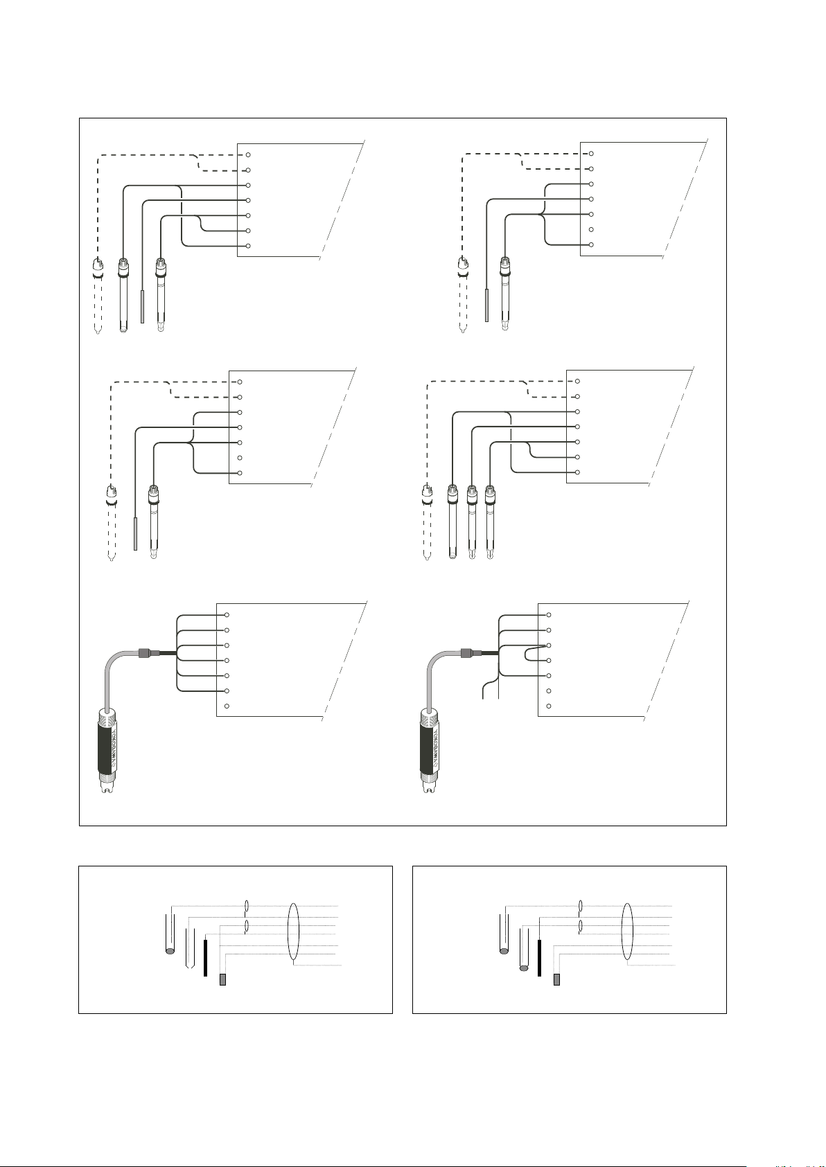
3-12 Installation and wiring
11 TEMPERATURE
1
2 TEMPERATURE
13 REFERENCE
14 SOLUTION GROUND (ORP)
15 pH
16 SHIELD
17
"All in one" pH & ORP (or rH)
Service code 01 set to pH
Service code 02 set to ORP (or rH)
S
eparate sensors ORP
Temp. sensors optional for indication
o
nly, not for compensation
Service code 01 set to ORP
*
Cable Markers
R
ED
BLUE
RED
B
LACK
RED
BLUE
BLUE
Red
*
Yellow
*
Green
*
11 TEMPERATURE
1
2 TEMPERATURE
1
3 REFERENCE
1
4 SOLUTION GROUND
15 GLASS (MEASURE)
16 SHIELD
17 SHIELD
11 TEMPERATURE
1
2 TEMPERATURE
13 REFERENCE
1
4 SOLUTION GROUND
15 GLASS (MEASURE)
1
6 SHIELD
17 SHIELD
Separate sensors ORP/ref sensor
Temp. sensors optional for indication
only, not for compensation
Service code 01 set to ORP
*
C
able Markers
R
ED
BLUE
BLUE
B
LACK
R
ED
W
HITE
Blue
*
G
reen
*
Separate sensors pH & ORP (or rH)
Temp. sensors optional for indication
only, not for compensation
Service code 01 set to pH
Service code 02 set to ORP (or rH)
*
Cable Markers
RED
BLUE
R
ED
BLACK
R
ED
B
LUE
B
LUE
R
ed
*
Yellow
*
Green
*
1
1 TEMPERATURE
1
2 TEMPERATURE
1
3 REFERENCE
14 METAL ORP SENSOR
15 GLASS (MEASURE)
16 SHIELD
17 SHIELD
1
1 TEMPERATURE
12 TEMPERATURE
13 REFERENCE
14 SOLUTION GROUND
1
5 GLASS (MEASURE)
16 SHIELD
17 SHIELD
Combined pH/ORP sensor
Temp. sensors optional for indication
only, not for compensation
Service code 01 set to ORP
*
Cable Markers
R
ED
BLUE
BLUE
BLACK
RED
WHITE
B
lue
*
Green
*
"All in one" ORP
Service code 01 set to ORP
Service code 03 set to off
Service code 04 set to off
11 TEMPERATURE
1
2 TEMPERATURE
13 REFERENCE
14 SOLUTION GROUND (ORP)
15 pH
16 SHIELD
17
11
12
1
3
14
16
15
>
Connections normal pH
A-15
B-13
CD-14
E-11
F-12
S-3 or 63
pH
ref
LE
temp
>
Conn ecti ons differen tial pH
A-15
B-14
C-13
D-17
E-11
F-12
S-3 or 63
pH
pH ref
LE
temp
Figure 3-11b. Sensor wiring
IM 12B6B3-E-E
Page 21
17 Overall Screen
11
12
12
13
14
14
16
15
13
14141615
17
11
17
11 Red
12 Blue
15 Core 16 Screen
White Co-axial cable
13 Core 14 Screen
Brown Co-axial Cable
14 (screen)
17 (overall screen)
12 (blue)
11 (red)
13 (core)
16 (screen)
15 (core)
Co-axial cable
(white)
Co-axial cable
(brown)
WF10 Cable
EXA pH TRANSMITTER / CONVERTER
11
12
13
14
15
16
17
11
12
13
17
15
16
14
Note that cables 14 & 17 connect to
terminals 17 & 14 respectively.
Installation and wiring 3-13
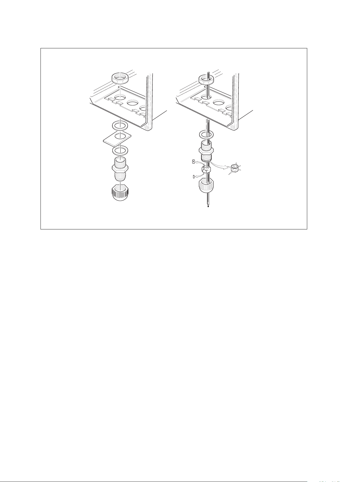
3-7-2. Sensor cable connection with special grommet
In order to seal multiple sensor cables into EXA PH402, a special grommet is provided that is designed to
accommodate one, two or three sensor cables (5 mm dia.) plus a liquid earth cable (2.5 mm dia.). In the
ack with the grommet are blanking pieces to close any unused holes. When correctly assembled, the
p
grommet maintains the IP65 (NEMA 4X) rating of the EXA PH402 housing.
Refer to figure 3-12 to assemble the grommet connections:
1. First remove the nut and standard rubber seal from the selected gland
. Discard the seal. This will be replaced later by the special grommet
2
3. Thread the cables through the nut and the gland
4. Connect the cables to their designated terminals
5. Arrange the cables to avoid tangles and insert the grommet between the gland and the nut
6. The grommet is split to permit the cables to be mounted after connection.
(This also ensures even length adjustment.)
7. Ensure that any unused holes are filled with the blanking pieces
8. Tighten the nut to form a firm seal. (Hand-tight is sufficient.)
Note: The special gland is intended to be used to seal the multiple cables from the Yokogawa flow fittings
such as FF20 and FP20. The designated cables are WU20 sensor cables, which are approximately
5 mm (0.2 “) in diameter, and 82895002 liquid earth cables, which are approximately 2.5 mm (0.1 “)
in diameter.
For sensor systems using a single cable, like the FU20 (FU25) and the PR20, PD20, PF20 and PS20, the
standard gland will accommodate the cable adequately. Single cables between approximately 7 mm and 12
mm (0.28 “ and 0.47 “) can be sealed properly with these glands.
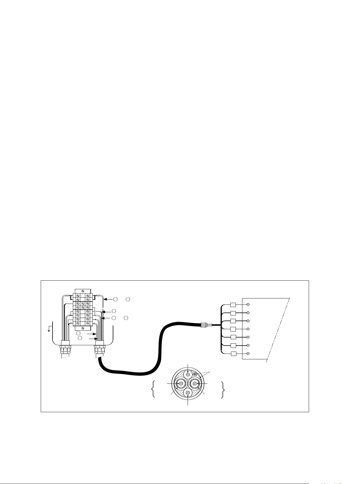
3-7-3. Sensor cable connections using junction box (BA10) and extension cable (WF10)
Where a convenient installation is not possible using the standard cables between sensors and converter, a
junction box and extension cable may be used. The Yokogawa BA10 junction box and the WF10 extension
cable should be used. These items are manufactured to a very high standard and are necessary to ensure
that the specifications of the system can be met. The total cable length should not exceed 50 metres
(e.g. 5 m fixed cable and 45 m extension cable). In the case of systems using dual high impedance sensors
(e.g. Pfaudler 18), then the cable length is restricted to 20 metres (fixed cable only, no extension with F10).
Fig. 3-12. Connection of WF10 extension cable and BA10/BP10 junction box
IM 12B6B3-E-E
Page 22
3 cm
heat shrink
9
cm
remove insulation
3 cm
cotton threads
11
12
17
15
16
13
14
3-14 Installation and wiring
Extension cable may be purchased in bulk quantities or in pre-finished lengths. In the case of bulk quantities
ut to length, then it is necessary to terminate the cable as shown below.
c
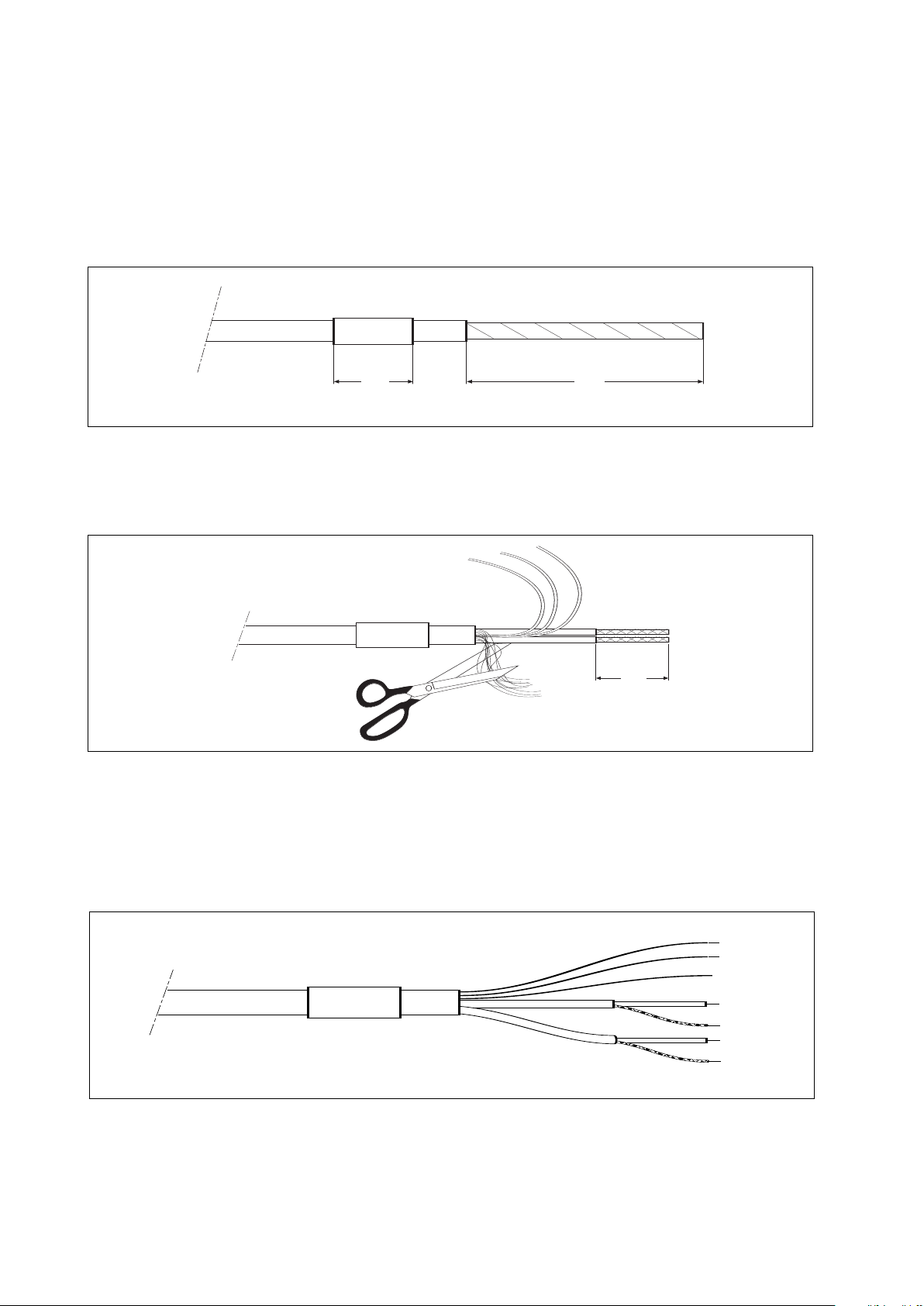
Termination procedure for WF10 cable.
1. Slide 3 cm of heat shrink tube (9 x 1.5) over the cable end to be terminated.
2. Strip 9 cm of the outer (black) insulating material, taking care not to cut or damage internal cores.
Fig. 3-13a.
3. Remove loose copper screening, and cut off the cotton packing threads as short as possible.
4. Strip insulation from the last 3 cm of the brown, and the white coaxial cores.
Fig. 3-13b.
5. Extract the coaxial cores from the braid, and trim off the black (low-noise) screening material as short as
possible.
6. Insulate the overall screen and the 2 coaxial screens with suitable plastic tubing.
7. Strip and terminate all ends with suitable (crimp) terminals and identify with numbers as shown.
Fig. 3-13.c
8. Finally shrink the overall heat shrink tube into position.
IM 12B6B3-E-E
Page 23
Installation and wiring 3-15
Figure 3-14. Sensor cable connections with special grommet
3-8. Tag plate mounting
When option /SCT is specified, a stainless steel tagplate is supplied with the designated Tag No. stamped
or engraved. It is mounted as shown in figure 3-14 using one of the cable glands.
IM 12B6B3-E-E
Page 24

IM 12B6B3-E-E
Page 25

Operation 4-1
4. OPERATION; DISPLAY FUNCTIONS AND SETTING
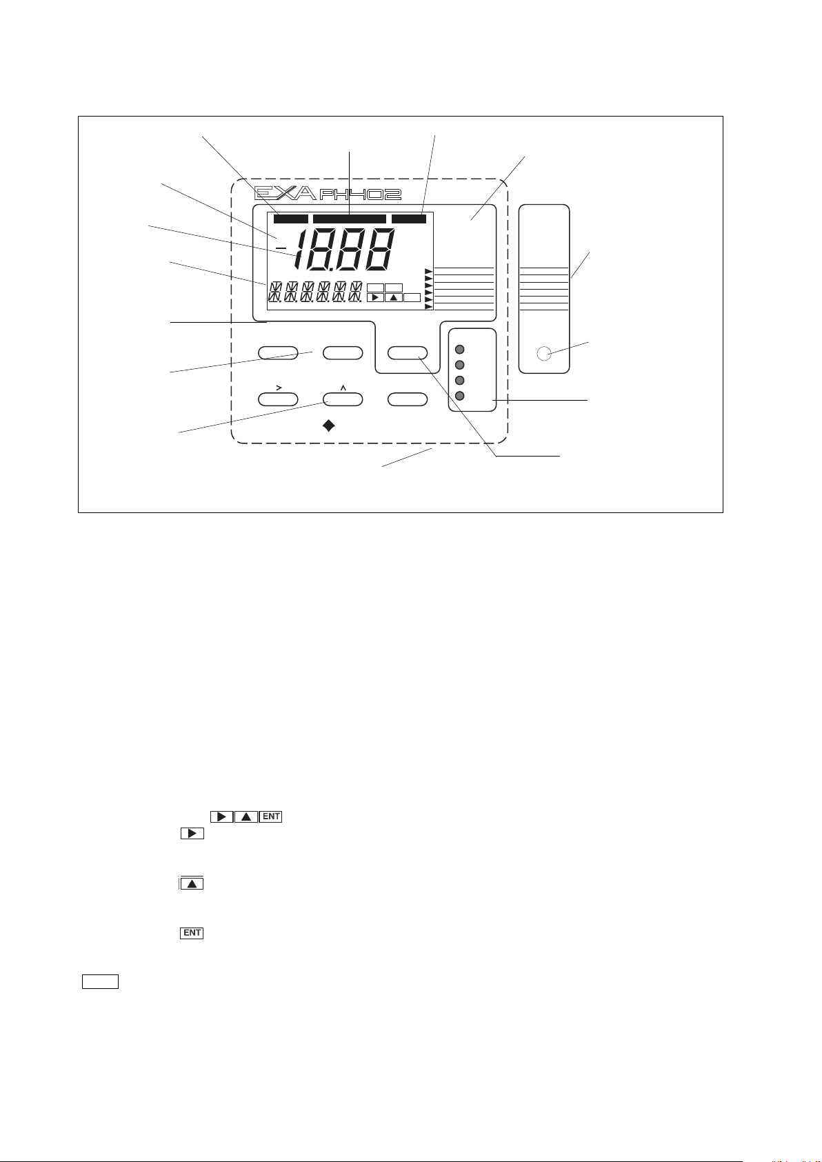
4-1. Operator interface
This section provides an overview of the operation of the EXA operator interface. The basic procedures for
obtaining access to the three levels of operation are described briefly. For a step-by-step guide to data
entry, refer to the relevant section of this instruction manual. Figure 4-1 shows the EXA operator interface.
LEVEL 1: Maintenance
These functions are accessible by pushbutton through a flexible front cover window. The functions make up
the normal day-to-day operations that an operator may be required to complete. Adjustment of the display
and routine calibration are among the features accessible in this way. (See table 4-1).
LEVEL 2: Commissioning
A second menu is exposed when the EXA front cover is removed and the display board is revealed. Users
gain access to this menu by pressing the button marked *in the lower right of the display board. This menu
is used to set such values as the output ranges and hold and wash features. It also gives access to the
service menu. (See table 4-1).
LEVEL 3: Service
For more advanced configuration selections, press the button marked *, then press “NO” repeatedly until
you reach SERVICE. Now push the “YES” button. Selecting and entering “Service Code” numbers in the
commissioning menu provide access to the more advanced functions. An explanation of the Service Codes
is listed in chapter 5 and an overview table is shown in chapter 10.
Table 4-1. Operations overview
Routine Function Chapter
Maintenance AUT CAL Calibration with programmed buffer solutions 6
MAN CAL Calibration with other buffer solutions 6
SAMPLE Grab sample calibration 6
DISPLAY Read auxiliary data or set message display 4
SETPOINTS Adjust alarm setpoints (when activated) 5
WASH Manual wash start (when activated) 5
MAN.IMP Manual start of impedance check 5
TEMPERATURE Select automatic or manual compensation 5
HOLD Switch hold on/off (when activated) 5
Commissioning SETPOINTS Adjust alarm setpoints 5
RANGE Adjust the output range 5
SET HOLD Activate the hold function 5
WASH Activate and configure the wash timer 5
Service SERVICE Fine tune the specialized functions of the 5
(Access to coded entries converter
from the commissioning
level)
NOTE:
All three levels may be separately protected by a password. See Service Code 52 in chapter 5 Service
Code table for details on setting passwords.
IM 12B6B3-E-E
Page 26
4-2 Operation
HOLD FAIL
YES NO
ENT
SETPOINTS
RANGE
SET HOLD
SERVIC
E
*
MEASURE
MAN.CAL
DISPLAY
HOLD
NO MODEYES
ENT
YOKOGAWA
M
ODE
TEMPERATURE
AUT.CAL
WASH
TEMP.MAN.
pH
mV
C
ONTACTS
S
1
S2
WASH/S3
FAIL/S4
Output hold flag
Units
Main display
Message display
Key prompt flags
Selection keys
YES : Accept setting
NO : Change setting
Adjustment keys
> : Choose digit to
adjust
^ : Adjust digit
ENT : Confirm change
Manual temperature
compensation flag
Figure 4-1. PH402 operator interface
Fail flag
Broken line indicates area
that can be seen through
front cover
Menu pointer flags
ommissioning
C
function menu
Commissioning
ode access key
m
Relay contact
status indicators
Measure/Maintenance
mode key
4-2. Explanation of operating keys
MODE key
This key toggles between the measuring and maintenance modes. Press once to obtain
access to the maintenance function menu.
Press again to return to the measuring mode (press twice when hold is activated).
YES/NO keys These ar
YES is used to accept a menu selection.
NO is used to reject a selection, or to move ahead to the next option.
DA
T
A ENTRY keys ( )
is used as a “cursor” key. Each press on this key moves the cursor or flashing digit
one place to the right. This is used to select the digit to be changed when entering
numerical data.
is used to change the value of a selected digit. Each pr
value by one unit.The value can not be decr
incr
key This is the commissioning mode key
*
IM 12B6B3-E-E
When the r
data entr
the ENT key is pressed.
menu. This can only be done with the cover r
been used to initiate the commissioning menu, follow the pr
as described above.
AUTO CAL
MAN CAL
DISPLAY
SETPOINT
WASH
MAN.IMP
TEMPERA
TURE
HOLD
e used to select choices fr
ease past nine to zer
o, then incr
equired value has been set using the > & ^ keys, press ENT to confirm the
. Please note that the EXA 402 does not r
y
om the menu.
ess on this key increases the
eased, so in order to obtain a lower value,
ease to the r
equir
ed number
.
egister any change of data until
. It is used to obtain access to the commissioning
emoved or opened. Once this button has
ompts and use the other keys
Page 27

Operation 4-3
4-3. Setting passcodes
4-3-1. Passcode protection
In Service Code 52, EXA users can set passcode protection for each one of the three operating levels, or
for any one or two of the three levels. This procedure should be completed after the initial commissioning
(setup) of the instrument. The passcodes should then be recorded safely for future reference.
When passcodes have been set, the following additional steps are introduced to the configuration and
programming operations:
Maintenance
Press MODE key. The display shows 000 and *PASS*
Enter a 3-digit passcode as set in Service Code 52 to obtain access to the Maintenance Mode
Commissioning
Press *key. The display shows 000 and *PASS*
Enter a 3-digit passcode as set in Service Code 52 to obtain access to the Commissioning Mode.
Service
From the commissioning menu, select *Service by pressing YES key. The display shows 000 and *PASS*
Enter a 3-digit passcode as set in Service Code 52 to obtain access to the Service Mode.
NOTE:
See Service Code 52 for the setting of passcodes.
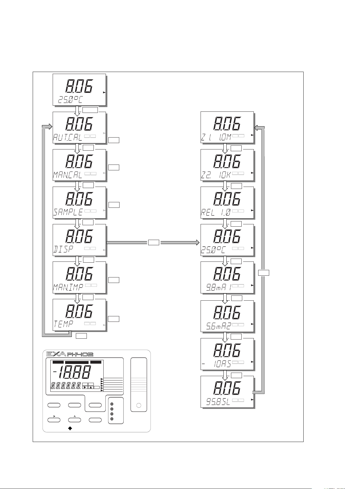
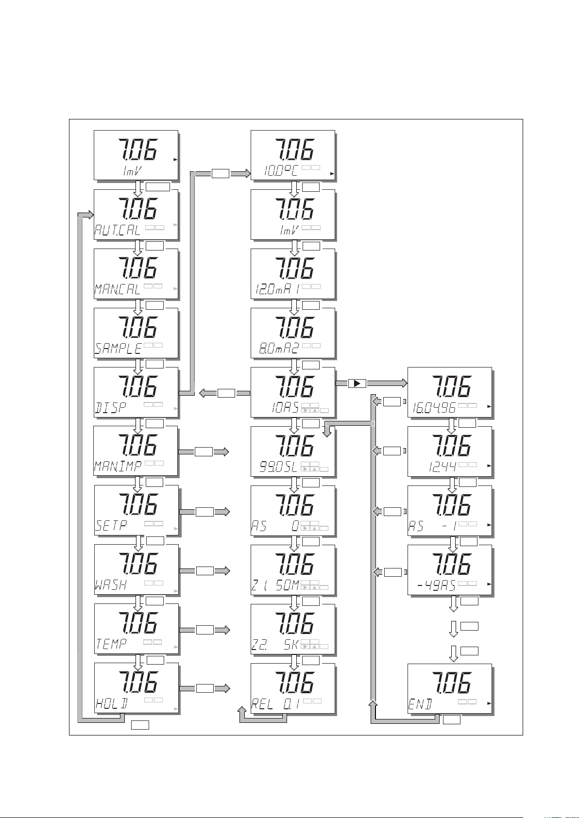
4-4. Display examples
The following pages show the sequence of button presses and screens displayed when working in some
standard configurations.
More or less options will be made available by the configuration of some service codes. For instance the
impedance measurement screens do not appear when impedance checking is switched off in service codes
03 and 04.
IM 12B6B3-E-E
Page 28
NO
Y
ES
pH
p
H
pH
YES
pH
YES
NO
pH
pH
pH
YES
(See Temp
menu
Chapter 5)
Y
ES NO
TEMP.
M
ODE
N
O
YES
YES
NO
NO
NO
(See Auto
calibration
Chapter 6)
(See Manual
calibration
Chapter 6)
Y
ES
N
O
YES NO
Y
ES NO
MEASURE
MAN.CAL
DISPLAY
HOLD
TEMP.
AUT.CAL
MAN.CAL
DISPLAY
AUT.CAL
MAN.CAL
(See Sample
calibration
Chapter 6)
SETPOINTS
RANGE
SET HOLD
SERVICE
*
WASH
HOLD FAIL
YES NO
ENT
MEASURE
MAN.CAL
DISPLAY
HOLD
NO MODEYES
ENT
YOKOGAWA
MODE
TEMPERATURE
AUT.CAL
TEMP.MAN.
pH
mV
CONTACTS
S1
S2
WASH/S3
FAIL/S4
pH
pH
pH
pH
pH
pH
pH
pH
NO
NO
NO
NO
NO
NO
NO
NO
Display Access
Impedance of input 1
Impedance of input 2
Process temperature
Current output 1
Current output 2
Software release number
Offset
(as. pot. or
zero point)
Efficiency
(slope)
Press YES to fix
the selected second
line of display
YES
YES
NO
Y
ES
N
O
YES
NO
Y
ES
N
O
Y
ES
NO
Y
ES
NO
YES
NO
YES
NO
DISPLAY
DISPLAY
DISPLAY
DISPLAY
DISPLAY
DISPLAY
DISPLAY
DISPLAY
12B6B3-21
D
isplay Functions pH (Default)
NO
YES
(See Manual
Impedance
check Chapter 5)
NO
4-4 Operation
4-5. Display functions
4-5-1. Display functions pH (default)
IM 12B6B3-E-E
Page 29
pH
pH
1
2B6B3-19
p
H
pH
T
EMP.
See Setpoint
Menu
chapter 5.5
See Wash
Menu
chapter 5.4
pH
NO
NO
NO
YES
YES
pH
pH
YES
NO
YES
NO
TEMP.
HOLD
HOLD
YES
NO
YES
NO
NO
DATE
pH
pH
pH
TIME
CAL -1
VALUE
Display Fuctions pH (ORP)
Service Code 01 Set for pH.
Service Code 02 Set for ORP
on parameter 2.
DISPLAY
D
ISPLAY
D
ISPLAY
D
ISPLAY
D
ISPLAY
"Logbook Scrolling"
The display can give information
about calibrations performed
with date and time.
The example below shows
A
symmetry Potential.
S
crolling of Data is also
available on Slope.
As Pot ORP
Impedance Input 1
Impedance Input 2
When these functions
are enabled in Service
Codes.
Measuring
Mode
As Pot
Display 2
Back to
the Top
p
H
Y
ES
NO
D
ISPLAY
DISPLAY
DISPLAY
DISPLAY
DISPLAY
DISPLAY
DISPLAY
D
ISPLAY
DISPLAY
D
ISPLAY
YES
NO
NO
NO
NO
NO
NO
NO
NO
N
O
p
H
NO
MODE
NO
NO
Y
ES
YES
YES
YES
YES
YES
YES
YES
NO
NO
NO
NO
pH
p
H
pH
pH
Y
ES
NO
Y
ES
NO
YES
NO
YES
NO
Y
ES
NO
YES
NO
YES
NO
pH
p
H
pH
pH
pH
pH
pH
pH
pH
MAN.CAL
MEASURE
M
AN.CAL
D
ISPLAY
HOLD
T
EMP.
A
UT.CAL
A
UT.CAL
D
ISPLAY
YES
NO
YES
NO
YES
N
O
YES
NO
YES
NO
YES
NO
YES NO
ENT
YES NO
ENT
Y
ES NO
E
NT
Y
ES NO
ENT
YES NO
ENT
NO
NO
YES
p
H
NO
YES
YES
See Temp
Menu
chapter 5
See Hold
Menu
chapter 5
YES
See Man.
Imp. Check
chapter 5
4-5-2. Display functions pH (ORP)
Operation 4-5
IM 12B6B3-E-E
Page 30

p
H
YES
NO
D
ISPLAY
YES NO
pH
TEMP.
YES NO
pH
HOLD
NO
TEMP.
HOLD
NO
YES
YES
NO
NO
See Setpoints Menu
Chapter 5
YES NO
See Hold Menu
Chapter 5
See Temp Menu
Chapter 5
See Wash Menu
Chapter 5
YES
YES NO
YES
pH
pH
MAN.CAL
NO
NO
YES
pH
MEASURE
MAN.CAL
D
ISPLAY
HOLD
TEMP.
A
UT.CAL
NO
YES
AUT.CAL
NO
MODE
DISPLAY
NO
DISPLAY
DISPLAY
DISPLAY
mV
D
ISPLAY
DISPLAY
DISPLAY
DISPLAY
D
ISPLAY
DISPLAY
NO
NO
NO
NO
NO
NO
NO
NO
mV
YES
NO
p
H Display
Current
Output 1
Current
O
utput 2
As Pot ORP
Impedance
Input 1
Impedance
Input 2
Software
Release
Version
NO
Slope
pH Sensor
As Pot
pH Sensor
YES
NO
YES
NO
YES
N
O
YES
NO
YES
NO
YES
NO
YES
NO
YES
NO
pH
pH
pH
pH
pH
pH
pH
pH
pH
12B6B3-20
See Auto Cal
C
hapter 6
S
ee Man Cal
Chapter 6
See Man Cal
Chapter 6
YES
YES NO
YES NO
YES
YES
YES
pH
pH
pH
pH
D
isplay Functions pH (rH)
Service Code 01 Set for pH.
Service Code 02 Set to rH
on parameter 2.
NO
T
emp Display
NO
NO
YES
pH
NO
YES
See Man. Imp.
check Chapter 5
4-6 Operation
4-5-3. Display functions pH (rH)
IM 12B6B3-E-E
Page 31

Parameter setting 5-1
5. PARAMETER SETTING
5-1. Maintenance mode
tandard operation of the EXA instrument involves use of the maintenance (or operating) mode to set up
S
some of the parameters.
Access to the maintenance mode is available via the six keys that can be pressed through the flexible
window in the instrument cover. Press the MODE-key once to enter this dialog mode.
OTE:
N
At this stage the user will be prompted for pass code where this has been previously set up in service code
52 in chapter 5.
Automatic calibration See “calibration” section 6.
Manual calibration See “calibration” section 6.
Sample calibration See “calibration” section 6.
Display setting See “operation” section 4.
Manual impedance check See “operation” section 5.
Setpoint Select and adjust setpoint (when enabled in service menu section 5,
service code 51). See adjustment procedure in §5-1-5 and §5-2-1.
Wash Manually start/stop wash cleaning (when enabled in service menu section
5, service code 51). See adjustment procedure in §5-1-4 and §5-2-4.
Temperature Set automatic or manual compensation and adjust manual reading (when
pH is set in section 5 service code 01). See adjustment procedure in
§5-1-1.
Hold Manually switch on/off HOLD (when enabled in commissioning menu
section). See adjustment procedure in §5-2-3..
IM 12B6B3-E-E
Page 32

T
EMP.MAN.
ENT
M
EASURE
NO MODEYES
ENT
YO
KOGAWA
MODE
CONTACTS
S1
S2
WASH/S3
FAIL/S4
S
ETPOINTS
R
ANGE
SET HOLD
SERVICE
*
W
ASH
NO
YES
p
H
AUT.CAL
YES
NO
pH
T
EMP.
pH
MODE
NO
NO
NO
NO
YES
NO
YES
pH
NO
YES
pH
NO
YES
5.1 Manual Temperature Selection & Adjustment.
(
pH Selected in Service Code 01)
Use
keys to
adjust and enter manual temperature setting
5-2 Parameter setting
5-1-1. Manual temperature selection and adjustment
H selected in service code 01.
p
IM 12B6B3-E-E
Page 33

5-1-2. Process temperature measuring in ORP mode
MEASURE
MODE
mV
NO MODEYES
ENT
YOKOGAWA
CONTACTS
S
1
S2
W
ASH/S3
FAIL/S4
S
ETPOINTS
RANGE
SET HOLD
SERVICE
*
WASH
N
O
Y
ES
mV
M
AN.CAL
YES NO
TEMP.
mV
MODE
NO
NO
NO
NO
YES
NO
YE
S
mV
NO
YES
mV
NO
YES
MEASURE
YES NO
mV
YES
5.2 Process Temperature Measuring in ORP mode.
(
ORP selected in Code 01)
Display return to
measuring mode with
temperature reading.
RP selected in service code 01.
O
Parameter setting 5-3
IM 12B6B3-E-E
Page 34

M
EASURE
N
O MODEYES
ENT
Y
OKOGAWA
M
ODE
CONTACTS
S1
S2
WASH/S3
FAIL/S4
SETPOINTS
RANGE
S
ET HOLD
SERVICE
*
WASH
12B6B3-27
pH
A
UT.CAL
YES
NO
p
H
pH
MODE
NO
NO
NO
YES
NO
YES
p
H
p
H
H
OLD
YES
NO
5.3 Manual Activation of Hold.
Note: The HOLD feature must first be activated in the commissioning mode section 5-2-3.
YES
NO
M
EASURE
NO
YES
pH
NO
YES
NO
HOLD
5-4 Parameter setting
5-1-3. Manual activation of HOLD
IM 12B6B3-E-E
Page 35

5-1-4. Manual wash start/stop
M
EASURE
NO MODEYES
ENT
Y
OKOGAWA
MODE
CONTACTS
S
1
S2
WASH/S3
F
AIL/S4
S
ETPOINTS
RANGE
SET HOLD
S
ERVICE
*
WASH
1
2B6B3-28
NO
YES
p
H
AUT.CAL
Y
ES
N
O
p
H
pH
M
ODE
NO
NO
NO
N
O
Y
ES
p
H
N
O
Y
ES
p
H
YES
MODE
YES
NO
5.4 Manual Wash Start/Stop.
Note: Wash must first be switched on in commissioning mode section 5-2-4,
and set for adjustment in the maintenance mode, by service code 51.
WASH ACTIVE press YES
to stop.
Parameter setting 5-5
IM 12B6B3-E-E
Page 36

M
EASURE
NO MODEYES
ENT
YOKOGAWA
MODE
CONTACTS
S1
S2
WASH/3
FAIL/S4
SETPOINTS
R
ANGE
S
ET HOLD
S
ERVICE
*
WASH
N
O
Y
ES
pH
A
UT.CAL
Y
ES
NO
pH
pH
M
ODE
NO
NO
NO
NO
Y
ES
pH
YES
NO
YES
N
O
Y
ES
pH
NO
YES
pH
YES
For adjustments,
follow procedures
as in section 5-2-1.
5.5 Setpoint Adjustment
For adjustments,
follow procedures
as in section 5-2-1.
Setpoint 3 and 4
when enabled in
service codes
42 and 43
Setpoint analogue
control output (mA2)
when enabled in code 31
Note: To enable adjustment of setpoints in
maintenance mode, Service Code 51
must be set to "ON".
Setpoints available will depend on their
configuration in the Service Code.
1
2B6B3-29/a
5-6 Parameter setting
5-1-5. Setpoint adjustment
IM 12B6B3-E-E
Page 37

5-1-6. Manual impedance check
MEASURE
NO MODEYES
ENT
YOKOGAWA
MODE
CONTACTS
S1
S2
WASH/3
FAIL/S4
S
ETPOINTS
RANGE
SET HOLD
SERVICE
*
W
ASH
12B6B3-29/b
NO
YES
pH
A
UT.CAL
YES
N
O
p
H
p
H
MODE
NO
NO
NO
N
O
YES
p
H
YES
NO
NO
YES
pH
5.6 Manual Impedance Check
Return to measuring
mode after updating
impedance check
Note: The manual impedance start
is available when the sensor impedance
m
easurement is enabled in Service
Code 3 and 4.
This enables the impedance data to be
updated immediately after a maintenance
event (e.g. replacing an electrode).
YES
Parameter setting 5-7
IM 12B6B3-E-E
Page 38

5-8 Parameter setting
5-2. Commissioning mode
n order to obtain peak performance from the EXA, you must set it up for each custom application.
I
Setpoints Alarms are set by default S1 - high process alarm
S2 - low process alarm
S3 - WASH
4 - FAIL
S
The setpoints are at arbitrary default value. Therefore, you must set these to
meaningful values, or set them to off. (See service codes 40 to 49 and user
interface codes 50 to 59).
Output ranges mA output 1 is set as default to 0 - 14 pH
mA output 2 is set as default to 0 - 100 °C
For enhanced resolution in more stable measuring processes, it may be desirable
to select 5 - 10 pH range, for example, and maybe 0 - 25 °C temperature range.
Service codes 30 to 39 can be used to choose other output parameters on mA
output 2. Choose from ORP, temperature, rH or PI control.
Hold The EXA converter has the ability to “hold” the output during maintenance periods.
This parameter should be set up to hold the last measured value, or a fixed value
to suit the pr
ocess.
Wash cleaner The EXA can be set up to control a wash cleaner. When using this function, the
timings must be configured for interval, wash and recovery periods.
Service This selection provides access to the service menu.
What follows are pictorial descriptions of typical frontplate pushbutton sequences for each parameter
setting function. By following the simple YES/NO prompts and arrow keys, users can navigate through the
process of setting range, setpoints, hold, wash and service functions.
IM 12B6B3-E-E
Page 39

ENT
pH
pH
pH
pH
pH
pH
pH
pH
ENT
ENT
ENT ENT
ENT
ENT
ENT
repeated
keystrokes
YES
NO
NO
NO
NO
NO
NO
NO
YES
NO
YES
NO
YES
SETPOINTS
RANGE
SET HOLD
SERVIC
E
*
MEASURE
MAN.CAL
DISPLAY
HOLD
MODE
TEMPERATURE
AUT.CAL
WASH
pH
Setpoints
YES
NO
YES
NO
YES
N
O
YES
N
O
YES
NO
5-2-1. Setpoints
Parameter setting 5-9
IM 12B6B3-E-E
Page 40

p
H
E
NT
Adjust setpoint value
using > ENT keys
as shown for setpoint 1.
>
Y
ES
N
O
Y
ES
N
O
Y
ES
N
O
NO
N
O
NO
Process Alarms on
S.3 and S.4 are
only available when
enabled in Service
Codes 40-49
Analogue control setpoint
is only available when
enabled in Service Code 31
pH
pH
pH
pH
ENT
Y
ES
NO
ENT
E
NT
ENT
ENT
Setpoint confirmedreturn to commissioning
menu.
YES
5-10 Parameter setting
IM 12B6B3-E-E
Page 41

YES
NO
YES
NO
NO
NO
NO
NO
NO
pH
YES
pH
pH
p
H
pH
pH
pH
SETPOINTS
RANGE
SET HOLD
SERVIC
E
*
MEASURE
MAN.CAL
DISPLAY
HOLD
MODE
TEMPERATURE
AUT.CAL
WASH
p
H
YES
NO
YES
ENT
YES
NO
pH
See facing
page
ENT
ENT
ENT
ENT
ENT
ENT
ENT
ENT
YES
NO
YES
NO
YES
NO
YES
NO
Parameter setting 5-11
5-2-2. Range
IM 12B6B3-E-E
Page 42

YES
N
O
NO
pH
E
NT
pH
YES
ENT
YES
ENT ENT
ENT
N
ote: Range 2 does not
a
ppear when P1 control
s
et on mA2
R
ange Selection Options
are determined
by Service Code 31
ENT
ENT
C
hoose Range to adjust, then set begin scale (0%)
and end scale (100%) of the mA output signal, using
t
he >, ,and ENT keys. Selection of mA output
(0-20 / 4-20 mA) is in Service Code 30.
>
E
NT
Range values set, return
to commission mode.
Y
ES
NO
Y
ES
NO
YES
NO
YES
NO
YES
N
O
OR
YES
5-12 Parameter setting
Note: Range 2 does not
appear when PI control
set on mA2
IM 12B6B3-E-E
Page 43

YES
NO
YES NO
YES
NO
YES
NO
YES
NO
YES
NO
YES
NO
NO
NO
NO
NO
NO
SETPOINTS
RANGE
SET HOLD
SERVIC
E
*
MEASURE
MAN.CAL
DISPLAY
HOLD
MODE
TEMPERATURE
AUT.CAL
WASH
p
H
YES
YES
NO
YES
NO
YES
NO
YES
NO
YES
YES
NO
H
old
HOLD active
last measured
value.
HOLD deactivated, return
to commissioning menu.
HOLD
YES
HOLD
Parameter setting 5-13
-2-3. Hold
5
IM 12B6B3-E-E
Page 44

YES
NO
ENT
HOLD
HOLD
H
OLD
H
OLD
HOLD
ENT
H
OLD
ENT
ENT
ENT
HOLD values set,
return to commissioning
menu.
E
NT
ENT
Set HOLD "fixed value"
for mA2.
YES
Set HOLD "fixed value"
for mA1.
5-14 Parameter setting
IM 12B6B3-E-E
Page 45
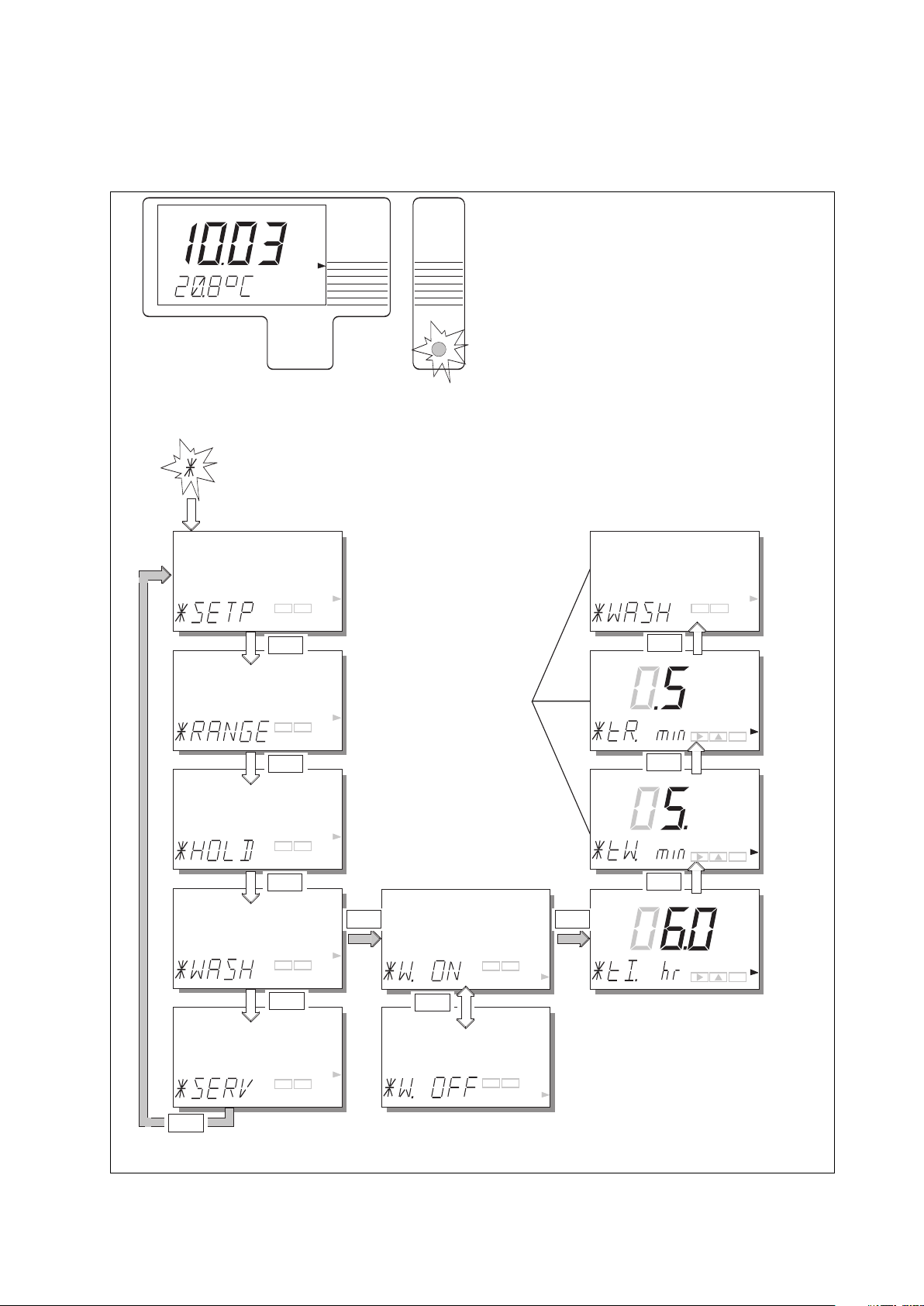
YES
NO
YES
NO
YES
NO
YES
NO
Y
ES
NO
YES
NO
YES
NO
NO
NO
NO
NO
NO
SETPOINTS
R
ANGE
S
ET HOLD
S
ERVICE
*
M
EASURE
M
AN.CAL
DISPLAY
H
OLD
MODE
T
EMPERATURE
AUT.CAL
W
ASH
pH
YES YES
W
ash
(NOTE: The menu item "WASH"
w
ill not appear unless selected in
Service Code 42)
NO
YES
NO
Wash system timings
are set with the >, ,
and ENT keys in the
setpoint menu
>
ENT
ENT
ENT
ENT
ENT
ENT
-2-4. Wash
5
Parameter setting 5-15
IM 12B6B3-E-E
Page 46

E
NT
YES
NO
YES
NO
YES
N
O
YES
NO
YES
NO
NO
NO
NO
NO
NO
S
ETPOINTS
RANGE
SET HOLD
SERVICE
*
MEASURE
MAN.CAL
DISPLAY
HOLD
MODE
TEMPERATURE
A
UT.CAL
WASH
pH
Service
ENT
ENT
ENT
YES
ENT
ENT
Example: Service Code 01
Select main parameter
for pH
for ORP
With the >, ,ENT keys
>
ENT
5-16 Parameter setting
-2-5. Service
5
IM 12B6B3-E-E
Page 47

5-3. Notes for guidance in the use of service coded settings
Parameter setting 5-17
IM 12B6B3-E-E
Page 48

5-18 Parameter setting
5-3-1. Parameter specific functions
Code 1 pH/ORP Choose the main measuring parameter. The option of the ORP input is used with
an inert metal electrode as measuring sensor which gives a reading directly in
millivolts. This signal can then be interpreted to give information about the
oxidation state of the process solution, and derived information like the absence
f a compound (like Cyanide for example which is destroyed in oxidizing
o
solutions).
Code 2 PRM.2 Enable the use of a second measuring parameter simultaneously with pH (the
main parameter).
With the correct sensor (e.g. FU20), ORP measurement is possible as parameter 2.
With the same sensor, rH measurement is possible as parameter 2, this is
calculated from pH and ORP and is a value which gives the oxidizing power of
the solution while compensating for the effect of pH.
This function is particularly useful for applications where both the pH and
oxidation-reduction potential of the process need to be controlled. The availability
of both measurements in a single system is much more convenient, (and more
economical) than two separate systems.
Note that in both cases a suitable sensor combination is needed to make this
possible. The Yokogawa FU20 (4-in-1) sensor can be used for this purpose, or a
combination of individual sensors. Contact your local Y
okogawa sales office for
advice regarding applications and sensor selection.
Code 3 & 4 Z1.CHK & The EXA PH402 has an impedance check capable of monitoring the impedance
Z2.CHK of all sorts of sensor systems. In order to "fine tune" this diagnostic tool it is
necessary to set it up to match the sensors used. The default settings give a
good setup for a conventional system comprising pH glass sensor and a
reference electrode, either as individual electrodes or as a combination style
sensor. The impedance limits will need to be adjusted to get the best from
systems using heavy duty, or fast response electrodes.
The impedance measuring system has a very wide span requirement. As it can
9
measure in kΩ and also in GΩ (10
) there are hardware switches to set high
range (1MΩ to 2 GΩ) or low range (1kΩ to 1MΩ) measuring. As a default the
system is set to measure high impedances on input 1 (the one normally used for
the pH glass sensor input) and low impedances on input 2 (the one nor
used for the r
ence input). Examples of wher
efer
e these settings need to be
mally
changed from the default, are Pfaudler enamel sensors which need two high
impedance settings, and Platinum sensors with a standard r
eference, which need
two low impedance settings.
In applications that have a tendency to leave deposits on the electrodes, and to
clog the reference sensor junction ther
ence sensor to initiate the wash cleaning pr
check on the r
efer
e is the possibility to use the impedance
ocess. This
provides an excellent way of handling variable processes and intermittent batch
operations.
The temperatur
e compensation of the impedance measur
ement is for conven-
tional pH glass sensors. When other sensors are used, switch this feature off.
Code 5
CAL.CK
The calibration checking featur
e, when enabled, gives security against entering
wrong calibration data. For example when aged sensors are due for
eplacement, the EXA flags an error message and prevents a calibration being
r
completed wher
e the subsequent measurement can only exhibit err
ors and drift.
Limits are set for the maximum permissible Asymmetry potential, and Slope.
IM 12B6B3-E-E
Page 49

Parameter setting 5-19
Code Display Function Function detail X Y Z Default values
Parameter specific functions
01 *PH.ORP Select main parameter pH 0 0 pH
ORP 1
02 *PRM.2 Enable 2nd parameter Off 0 0 Off
ORP 1
rH 2
03 *Z1.CHK Impedance check 1 Low 0 1.1.1
High 1 High
Temp comp off 0
Temp comp on 1 On
Imp check off 0
Imp check on 1 On
*Z.L.xΩ Low impedance limit Press NO to step through choice of units, 1 MΩ
x = None, K, M or G press YES to select units, then use the
>, ^ ENT keys to set the value
*Z.H.xΩ High impedance limit Press NO to step through choice of units, 1 GΩ
press YES to select units, then use the
>, ^ ENT keys to set the value
04 *Z2.CHK Low 0 0.0.1 Low
High 1
Temp comp off 0Off
Temp comp on 1
Imp check off 0
Imp check on 1 On
Imp check on with wash start high imp. 2
*Z.L.xΩ Low impedance limit Press NO to step through choice of units, 100 Ω
x = None, K, M or G press YES to select units, then use the
>, ^ ENT keys to set the value
*Z.H.xΩ High impedance limit Press NO to step through choice of units, 200 kΩ
press YES to select units, then use the
>, ^ ENT keys to set the value
05 *CAL.CK Calibration check Asymmetry check off 0 1.1
Asymmetry check on 1 On
Slope check of
Slope check on 1 On
06-09 Not used
f
0
IM 12B6B3-E-E
Page 50

5-20 Parameter setting
-3-2. Temperature compensation and measuring functions.
5
Code 10 T.SENS Selection of the temperature compensation sensor. The default selection is the
Pt1000 Ohm sensor, which gives excellent precision with the two wire
connections used. The other options give the flexibility to use a very wide range
f other pH sensors.
o
Code 11 T.UNIT Celsius or Fahrenheit temperature scales can be selected to suit user preference.
Code 12 T.ADJ With the process temperature sensor at a stable known temperature, the
temperature reading is adjusted in the main display to correspond. The calibration
is a zero adjustment to allow for the cable resistance, which will obviously vary
with length.
The normal method is to immerse the sensor in a vessel with water in it, measure
the temperature with an accurate thermometer, and adjust the reading for
agreement.
Code 13 T.COMP Process compensation automatically allows for changes in the pH of the process
with temperature. The characteristic of each process will be different, and the
user should determine if this feature is to be activated, and what compensation
figure to choose.
The compensation is given in pH per 10 °C.
Example:- For pure water with an alkali dose, (e.g. boiler feed water) a coefficient
of approx. 0.35pH can be expected. However, applications vary and a
simple test will determine what if any coefficient is suitable for the
process.
IM 12B6B3-E-E
Page 51

Parameter setting 5-21
Code Display Function Function detail X Y Z Default values
Temperature measuring and compensation functions
10 *T.SENS Temperature sensor Pt1000 0 0 Pt1000
Pt100 1
3kBalco 2
5k1 3
8k55 4
10kPTC 7
11 *T.UNIT Display in °C or °F °C 0 0 °C
°F 1
12 *T.ADJ Calibrate temperature Adjust to allow for cable resistance None
13 *T.COMP Set temp comp Compensation for process changes off 0 0 Off
Compensation for process changes on 1
*T.COEF Adjust process TC Set for TC in pH per 10 °C - 0.0 pH per
10 °C
14-19 Not used
IM 12B6B3-E-E
Page 52

5-22 Parameter setting
-3-3. Calibration Functions
5
Code 20 ∆t.SEC & These functions are used to determine the stability level demanded by the EXA as
∆pH acceptance criteria for the automatic calibration. The default settings give a good
calibration for general purpose electrode systems with a fast response. Where
eavy duty electrodes are used, or when low temperatures are concerned, these
h
values should be adjusted.
When adjusting these settings, the longer the time interval and the smaller the pH
change, the more stable will be the reading. However, it is important to bear in
mind that the time taken to reach stability is an exponential function, and too
ambitious a setting will cause the instrument to wait for a very long time before
accepting a calibration.
Code 21 AS.LOW & Limit values for the drift of an electrode system before an error is signalled when
AS.HI a calibration is done. These default values should be adjusted to suit the
application, this will be especially important will enamel or Antimony probes.
Code 22 SL.LOW & Limit values for acceptable slope (sensitivity) calibrations.
SL.HI
Code 23 ITP, SLOPE Values can be entered directly in this section. These data can be provided by the
& ASPOT manufacturer of the probe, or by the users laboratory etc. They are determined
independently of the measuring loop.
NOTE: it is not necessary to enter this data in most cases as the EXA
automatically does this while performing a calibration. The feature is used
in the case of special electrode systems and where calibration in the
process environment is not possible.
Code 24, Buffer tables The following buffer calibration tables are programmed into the EXA. They are the
25, & 26 primary buffer standards according to NIST (formerly NBS) and various other
national standards. We strongly recommend the use of these buffer solutions as
they give the best buffer capacity, reliability and accuracy when calibrating.
Table 5-1.
pH 4 pH 7 pH 9 pH 4 pH 7 pH 9
0 °C 4.00 6.98 9.46 45 °C 4.05 6.83 9.04
5 °C 4.00 6.95 9.40 50 °C 4.06 6.83 9.01
10 °C4.00 6.92
15 °C 4.00 6.90 9.28 60 °C 4.09 6.84 8.96
20 °C 4.00 6.88 9.23 65 °C 4.11 6.84 8.94
C
°
25
30
35 °C 4.02 6.84 9.10 80 °C 4.16 6.86 8.89
40 °C 4.04 6.84 9.07
4.01
C
°
4.02
6.87
6.85
9.33
9.18
9.14
55 °
70
75
C
C
°
C
°
4.08 6.83
4.13
4.15
6.85
6.85
8.99
8.92
8.90
These tables may be adjusted in the case that the user wishes to use other
.ID
Code 27
calibration solutions. The "name" of the buf
ompt. The other values can then be adjusted in sequence.
pr
fer can be changed at the *BUF
Zero Point As an alternative to Asymmetry Potential, the Zero point can be used to define
and calibrate the EXA pH unit.
Note that this method conforms to the DIN standard for instruments
No. IEC 746-2.
IM 12B6B3-E-E
Page 53

pH
mV
ITP
As pot
0 mV
0 ºC
10 ºC
25 ºC
12B6B3-12
ASYMMETRY POTENTIAL
mV
500
0
- 200
14
pH
ITP
Zero Point
0
7
Parameter setting 5-23
Code Display Function Function detail X Y Z Default values
Calibration functions
20 *∆t.SEC Stability check time 5 sec.
*∆PH Stability check pH 0.02 pH
21 *AS.LOW As Pot low limit -120 mV
*AS.HI As Pot high limit 120 mV
22 *SL.LOW Slope low limit 70 %
*SL.HI Slope high limit 110 %
23 *ITP Set ITP Preset calibration data from manufacturer 7.00 pH
(pH) *SLOPE Set slope or from laboratory determinations. 100 %
*ASP.1D Set As Pot For the main parameter 0.0 mV
Press YES to confirm 0.1 mV resolution,
then set value with >, ^, ENT keys.
Press NO to change to *ASP.
*ASP Set As Pot For the main parameter
Press YES to confirm 1 mV resolution,
then set value with >, ^, ENT keys.
*ASPmV Set As Pot ORP For parameter 2 (when activated in
service code 02)
23 *ASP.1D Set As Pot (ORP) For the main parameter
(ORP) Press YES to confirm 0.1 mV resolution,
then set value with >, ^, ENT keys.
Press NO to change to *ASP.
*ASP Set As Pot For the main parameter
Press YES to confirm 1 mV resolution,
then set value with >, ^, ENT keys.
24 *BUF.ID Buffer table 4 Buffer tables to NIST (formerly NBS)
25 *BUF.ID Buffer table 7 (see section 10 for table details)
26 *BUF.ID Buffer table 9 User adjustable for special requirements
27 *ZERO.P Enable zero point in Disable zero point (enable As Pot) 0 0 Disabled
pH units Enable zero point (disable As Pot) 1
28-29
Not used
Fig. 5-1.
IM 12B6B3-E-E
Page 54

5-24 Parameter setting
5-3-4. mA Output functions
ode 30 *mA Select required output signal. 0-20 or 4-20mA to suit associated
C
equipment (Recorders, controllers etc.).
Code 31 OUTP.F Select the parameters to transmit on the two mA output signals mA1 &
mA2.
ote: The available choices are affected by the selection of primary parameter (pH/ORP) in
N
service code 01, and the selection of secondary parameter (off/ORP/rH) in service code 02.
With pH selected as parameter 1, the default configuration is with mA1
as linear pH output, and mA2 as temperature.
The choices for mA1 (on terminals 61 & 62) are: linear pH, pH table output
(21pt curve), linear parameter 2 (ORP/rH).
The choices for mA2 (a terminal 64 & 65) are: linear pH, pH table, linear
temperature, pH control (PI), parameter 2 control (PI).
Note: To transmit pH (parameter 1) and ORP/rH (parameter 2) simultaneously, set mA1 for
ORP/rH (parameter 2) and mA2 for pH (parameter 1). Service code 31 set to 2.0.
P.I. Control When PI control is selected for mA2 (choice 3 or 4) a further configuration
step is needed.
*D/R
This sets the direction of the control action. Direct is a rising output with
rising signal. Reverse is a falling output with rising signal.
With ORP selected as parameter 1, the default configuration is with
mA1 as linear ORP output and mA2 as temperature. The choices for mA1
(on terminals 61 & 62) are: linear ORP, ORP table output (21pt curve).
The choices for mA2 (a terminal 64 & 65) are: linear ORP, ORP table, linear
temperature, ORP control (PI).
P.I. Control When PI control is selected for mA2 (choice 3) a further configuration
step is needed.
*D/R This sets the direction of the control action. Direct is a rising output with
rising signal. Reverse is a falling output with rising signal.
Code 32 BURN Diagnostic error messages can signal a problem by sending the output
signals upscale or downscale (22mA or 0/3.5mA). This is called upscale or
downscale bur
nout, fr
om the analogy with ther
mocouple failur
e signalling of
a burned-out or open circuit sensor. In the case of the EXA the diagnostics
are extensive and cover the whole range of possible sensor faults.
Code 33
RG.mA2
This function sets the pr
tional range for the mA output contr
opor
ol signal
Code 34 tI.mA2 This function sets the integral time for the mA output control signal
Code 35 T
& 36
ABLE
The table function allows the configuration of an output curve by 21 steps
vals of 5%)
(inter
Table 5-2.
0%
5% 1 mA 4.8 mA 55% 11 mA 12.8 mA
10% 2 mA 5.6 mA 60% 12 mA 13.6 mA
15% 3 mA 6.4 mA 65% 13 mA 14.4 mA
20% 4 mA 7.2 mA 70% 14 mA 15.2 mA
25% 5 mA
30% 6 mA 8.8 mA 80% 16 mA 16.8 mA
35% 7 mA 9.6 mA 85% 17 mA 17.6 mA
40% 8 mA
45% 9 mA
0-20 mA
0 mA
4-20 mA
4.0 mA
8.0 mA
10.4 mA
11.2 mA
50% 10 mA
75% 15 mA
90% 18 mA
95% 19 mA
100% 20 mA 20.0 mA
0-20 mA
4-20 mA
12.0 mA
16.0 mA
18.4 mA
19.2 mA
IM 12B6B3-E-E
Page 55

Parameter setting 5-25
Code Display Function Function detail X Y Z Default Values
mA Outputs
30 *mA output signal 0-20 mA on mA1 0 1.1
4-20 mA on mA1 1 mA1 4-20
0-20 mA on mA2 0
4-20 mA on mA2 1 mA2 4-20
31 The choices below appear when pH was selected in service code 01
pH *OUTP.F Output Parameter pH on mA1 0 0.2 pH on
mA1
pH (table) on mA1 1
Parameter 2 (ORP or rH) on mA1 2
pH on mA2 0
pH (table) on mA2 1
Temperature on mA2 2 Temp. on
mA2
pH PI control on mA2 3
Parameter PI control on mA2 4
*D/R Direct or reverse For rising signal, set 0 0 Reverse
acting PI control for decreasing mA output
For rising signal, set 1
for increasing mA output
31 The choices below appear when ORP was selected in service code 01
ORP *OUTPUT.F Output parameter ORP on mA1 0 0.2 ORP on
ORP (table) in mA1 1 mA1
ORP on mA2 0
ORP (table) on mA2 1
Temperature on mA2 2 Temp on
ORP PI control on mA2 3 mA2
*D/R Direct or reverse For rising signal, set 0 0 Reverse
acting PI control for decreasing mA output
For rising signal, set 1
for increasing mA output
32 *BURN Burn function mA 1 No burnout 0 0.0 No Burn.
mA 1 Burnout downscale 1
mA 1 Burnout upscale 2
mA 2 No burnout 0 No Burn.
mA 2 Burnout downscale 1
mA 2 Burnout upscale 2
33 *RG.mA2 PI range Proportional range for mA control signal
*pH.mA2
*mV.mA2 parameter selected 2.0 rH
*rH.mA2 in code 31 50 mV
34 *tI.mA2 Integral time 100 sec.
35 *TABL1 Output table for mA1
*0% Linearisation table for mA1 in 5% steps.
*5% The measured value is set in the main
*10% display using the >, ^, ENT keys, for
...
...
*90% be skipped, and a linear interpolation will
*100% take place.
ABL2
36
37-39 Not used
*T
*0% Linearisation table for mA2 in 5% steps.
*5% The measured value is set in the main
*10% display using the >, ^, ENT keys, for
... each of the 5% interval steps.
... Where a value is not known, that value may
*90%
*100% take place.
Display depends on
(for PI contr
Output table for mA2
ol)
(use >, ^, ENT keys to adjust value) 1.0 pH
each of the 5% interval steps.
e a value is not known, that value may
Wher
be skipped, and a linear interpolation will
IM 12B6B3-E-E
Page 56

5-26 Parameter setting
5-3-5. Contact outputs
Code 40 *S1 & *S2 Process relays can be set for a variety of alarm and control function.
& 41
Digit "X" sets the type of trigger:
Off means that the relay is not active
ow setpoint means that the relay is triggered by a decreasing measurement.
L
High setpoint means that the relay is triggered by an increasing measurement
"HOLD" active means that there is maintenance activity in progress so the
measurement is not live.
For *S3 There is the extra possibility to set up for a wash controller.
For *S4 There is the extra possibility to set up for "FAIL" indication.
Digit "Y" sets the control action:
Process alarm is a simple On/Off trip controlled by the high/low setpoint.
Proportional duty cycle control has a pulse width modulation for proportional
dosing with solenoid valves.
Proportional frequency control is used for controlling electrically positioned valves.
emperature alarm is an On/Off trip on the measured temperature.
T
Digit "Z" sets the control parameter:
m on main process
Alar
Control on main process
(Main process means pH/ORP depending on the setting of service code #1)
Alarm on rH
Control on rH
(Available only when pH set in service code #1 & parameter 2 is set to rH in
service code #2.
IM 12B6B3-E-E
Page 57

Parameter setting 5-27
Code Display Function Function detail X Y Z Default values
Contacts
40 *S1 Relay 1 settings Off 0 2.0.0
Low setpoint 1
High setpoint 2 High
Note: Main process “HOLD” active 3
means pH or ORP Process alarm 0 Alarm
whichever is set in Proportional duty cycle control 1
code #1 Proportional frequency control 2
Temperature alarm 3
Alarm on main process 0 Main
PI control on main process 1
Alarm on rH 2
PI control on rH 3
41 *S2 Relay 2 settings Off 0 1.0.0
Low setpoint 1 Low
High setpoint 2
Note: “HOLD” active “HOLD” active 3
relay contact is used Process alarm 0 Alarm
to indicate when the Proportional duty cycle control 1
measuring mode is Proportional frequency control 2
interrupted Temperature alarm 3
Alarm on main process 0 Main
PI control on main process 1
Alarm on rH 2
PI control on rH 3
42 *S3 Relay 3 settings Off 0 4.0.0
Low setpoint 1
High setpoint 2
“HOLD” active 3
Note: “WASH” relay Wash control 4 WASH
contact is used to Process alarm 0 Alarm
control the flow of Proportional duty cycle control 1
cleaner to a sensor Proportional frequency control 2
e alarm 3
ol on main process 1
m on rH
1
2
m 4 FAIL
m
equency control 2
tional fr
m
e alar
ol on main pr
m on rH
ocess
2
0
3
1
2
Alar
m
43
emperatur
wash nozzle
*S4 Relay 4 settings Off 0 4.0.0
elay
AIL” r
Note: “F
contact is used to
indicate when the Proportional duty cycle control 1
diagnostics detect a
oblem
pr
T
Alarm on main process 0 Main
PI contr
Alar
PI control on rH 3
Low setpoint
High setpoint
“HOLD” active 3
Fail alar
ocess alar
Pr
opor
Pr
emperatur
T
Alarm on main process 0 Main
PI contr
Alar
PI control on rH 3
IM 12B6B3-E-E
Page 58

5-28 Parameter setting
Code 44 *D.TIME The delay time sets the minimum relay switching time. This function can be
adjusted to give a good alarm function in a noisy process, preventing the relay
from "chattering" or repeatedly switching when the signal is close to the setpoint.
*PH.HYS The hysteris is the value beyond the setpoint that the measured value must
*mV.HYS exceed before the control function will start working.
*rH.HYS
*T.HYS
Code 45 *RANGE Proportional range is the value above (or below) the setpoint that generates full
output in proportional control. This is in the units of the main parameter (pH or
mV).
*rH.RNG This is the proportional range in rH and is only enabled when the converter is set
up for rH measurement.
*PER. The time period of the overall pulse control cycle (one ON and one OFF period).
See fig. 5-3.
*FREQ. The maximum frequency for the pulse frequency control. See fig 5-4.
Code 46 *tI.CNT The integral time for the PI control settings.
Code 47 *EXPIR When a system is set up to control on the relay outputs, the expiry time can be
enabled to warn of an ineffective control. In other words, when the setpoint is
exceeded for more than 15 minutes an error message is generated. This can
mean, for example, that the reagent tank is empty.
IM 12B6B3-E-E
Page 59

90%
100
50
0
on
t
t
of
f
10%
50%
50%
10%
90%
100
50
0
SC
0.3 s
12D7C21-13
PULSE FREQUENCY CONTROL
Parameter setting 5-29
Code Display Function Function detail X Y Z Default values
Contacts (continued)
44 *D.TIME Delay time Minimum relay switching time 0.2 sec.
*PH.HYS Hysteresis pH Minimum pH/ORP change for relay reset 0.1 pH
*mV.HYS Hysteresis ORP after switching 10 mV
*rH.HYS Hysteresis rH Minimum rH change for relay reset 0.2 rH
after switching
*T.HYS Hysteresis temp. Minimum temperature change for relay 1 °C
reset after switching (fig. 5-2)
45 *RANGE Proportional range When proportional control selected 1 pH
in code 40, 41, 42 or 43 (10 mV)
*rH.RNG Proportional range rH When rH proportional control selected in 2 rH
code 40, 41, 42 or 43
*PER. Duty cycle period Pulse control On time + Off time (fig. 5-3) 10 sec.
*FREQ. Maximum frequency 100% value for frequency control (fig. 5-4) 70 p/m
46 *tI.CNT Integral time Integral time for relay controls when 100 sec.
PI is set
47 *EXPIR Expiry time Warning of ineffective control action On 0 0 Off
Warning of ineffective control action Off 1
*tE min Set expiry time 15 min
48-49 Not used
pH/mV
Setpoint
Fig. 5-2.
% duty cycle control
LED off
Hys.
LED on
Delay time Delay time
LED off
t (sec)
% controller output
Maximum pulse frequency
50 % pulse frequency
Proportional
range
Setpoint
Fig. 5-3.
pH
% of setpoint value
ime
T
Setpoint
Proportional
range
pH
% of setpoint value
No pulses
Time
Fig. 5-4.
IM 12B6B3-E-E
Page 60

5-30 Parameter setting
5-3-6. User interface
Code 50 *RET. When Auto return is enabled, the converter reverts to the measuring mode from
anywhere in the configuration menus, when no button is pressed during the set
time interval of 10 minutes.
ode 51 *MODE The adjustment of the contact setpoints, the manual operation of the wash
C
system and a manual impedance check (on demand) can be setup for operation
in the maintenance mode. (Through the closed front cover).
Code 52 *PASS Passcodes can be set on any or all of the access levels, to restrict access to the
instrument configuration.
Code 53 *Err.4.1 Error message configuration. Two different types of failure mode can be set.
Hard fail gives a steady FAIL flag in the display, and a continuous contact closure.
All the other contacts (controls) are inhibited (except HOLD contacts), and a Fail
signal is transmitted on the outputs when enabled in code 32.
Soft fail gives a flashing FAIL flag in the display, and the relay contacts are pulsed.
The other contacts (controls) are still functional, and the controller continues to
work nor
mally. The call for maintenance is a good example of where a SOFT fail is
useful. A warning that the regular maintenance is due, should not be used to shut
down the whole measurement.
*SOFT If soft set to 1, Soft fail only gives a flashing FAIL flag in the display and no
pulsing contact
Code 54 Not used
Code 55 *CALL.M Call for maintenance is a contact trigger to signal that the system has been in
service for longer than the set time without calibration. The user can set up to
250 days as a routine service interval.
Code 56 *DISP The display resolution can be set to either 0.01pH or 0.1pH. Not applicable to the
ORP (mV) display
.
IM 12B6B3-E-E
Page 61

Parameter setting 5-31
Code Display Function Function detail X Y Z Default values
User interface
50 *RET Auto return Auto return to measuring mode Off 0
Auto return to measuring mode On 1 1 On
51 *MODE Mode setup Setpoints in maintenance mode Off 0 0.0.0 Off
Setpoints in maintenance mode On 1
Wash in maintenance mode Off 0 Off
Wash in maintenance mode On 1
Manual impedance check Off 0 Off
Manual impedance check On 1
52 *PASS Passcode Maintenance passcode Off 0 0.0.0 Off
Note # = 0 - 9, where Maintenance passcode On #
0 = no passcode Commissioning passcode Off 0 Off
1=111, 2=333, 3=777 Commissioning passcode On #
4=888, 5=123, 6=957 Service passcode Off 0 Off
7=331, 8=546, 9=847 Service passcode On #
53 *Err.4.1 Error setting Impedance low (input 1) Soft fail 0
Impedance low (input 1) Hard fail 1 1 Hard
*Err.5.1 Impedance high (input 1) Soft fail 0
Impedance high (input 1) Hard fail 1 1 Hard
*Err.4.2 Impedance low (input 2) Soft fail 0
Impedance low (input 2) Hard fail 1 1 Hard
*Err.5.2 Impedance high (input 2) Soft fail 0
Impedance high (input 2) Hard fail 1 1 Hard
*Err.07 Temperature too high Soft fail 0
Temperature too high Hard fail 1 1 Hard
*Err.08 Temperature too low Soft fail 0
Temperature too low Hard fail 1 1 Hard
*Err.09 pH out of range Soft fail 0
pH out of range Hard fail 1 1 Hard
*Err.11 Response (half-time fail) Soft fail 0 0 Soft
Response (half-time fail) Hard fail 1
*Err.16 Call for maintenance Soft fail 0 0 Soft
Call for maintenance Hard fail 1
.22
r
*Er
*SOFT
54 Not used
55
56
57-59
*CALL.M Call for maintenance Set time limit for calibration Off 0 0 Off
esolution
*DISP
Display r
Control time-out Soft fail 0 0 Soft
Control time-out Hard fail 1
LCD + Fail contact 0 0 LCD/Fail
LCD only
Set time limit for calibration On
Set pH decimal display
Set pH decimal display 0.01pH 1 1 0.01 pH
Not used
0.1 pH
1
1
0
IM 12B6B3-E-E
Page 62

5-32 Parameter setting
5-3-7. Communication setup
Code 60 *COMM. The settings should be adjusted to suit the communicating device connected to
the RS485 port.
*SET.
*ADDR.
or the Yokogawa PC402 software package, the default settings match the
F
software as shipped.
Code 61 *HOUR The clock/calendar for the logbook is set for current date and time as reference.
*MINUT
*SECND
*YEAR
*MONTH
*DAY
Code 62 *ERASE Erase logbook function to clear the recorded data for a fresh start. This may be
desirable when re-commissioning an instrument that has been out of service for a
while.
5-3-8. General
Code 70 *LOAD The load defaults code allows the instrument to be returned to the default set up
with a single operation. This can be useful when wanting to change from one
application to another.
Code 71 *tH.CHK The wash cleaner can be used to test the response of the electrode system, see
fig. 5-5.
The online response check gives a very good indication of the condition of the
electrode system. The first sign of deterioration of the sensors is usually the
increase in response time.
Code 72 *W. REV Wash reverse is used for very difficult applications where the process rapidly
attacks the sensors, or coats them, or otherwise spoils the measurement. The
wash is then operational most of the time, and is switched of
f to measure. This
technique gives an output which is updated on a sample and hold basis. To
obtain continuity of output is important therefore to set the hold to ON in the
commissioning menu.
Code 79 *CUST.D Load customer defaults. This code allows the instrument to be returned to the
y default set, except that buf
factor
fer tables (code 24,25,26) ar
e unchanged.
IM 12B6B3-E-E
Page 63

pH
GOOD SENSOR
AGED SENSOR
Fault E11
DYNAMIC RESPONSE CHECK AFTER WASH
t
w
t
R
t
half
Time
7.0
4.5
2.0
Parameter setting 5-33
Code Display Function Function detail X Y Z Default values
Communication
60 *COMM. Communication Set communication Off 0 0.1 Off
Set communication On 1
Communication write enable 0 write
Communication write protect 1 protect
*SET. Baud rate & parity Baud rate 1200 0 3.1
2400 1
4800 2
9600 3 9600
Parity Off 0
Odd 1 Odd
Even 2
*ADDR. Network address Set address 00 to 15 00
61 *HOUR Clock setup Adjust to current date and time using
*MINUT >, ^ and ENT keys
*SECND
*YEAR
*MONTH
*DAY
62 *ERASE Erase logbook Press YES to clear logbook data
63-69 Not used
Code Display Function Function detail X Y Z Default values
General
70 *LOAD Load defaults Reset configuration to default values
71 *tH.CHK Half-time check Response check when washing Off 0 0 Off
Response check when washing On 1
72 *W. REV Wash reverse Long wash, short measuring time Off 0
Long wash, short measuring time On 1
73-78 Not used
79 *CUST.D Load Customer Reset configuration to default values
Defaults except buffer tables
Contact S3 is used to control the wash cycle.
- Adjustable parameters :
Cleaning time or washing time (tw)Recovery
time after washing (tr)
Interval time for wash cycle
An on-line dynamic response test of the
ode can be activated after cleaning.
electr
In the example shown, within the “halftime” the pH should recover to more than
4.5. Otherwise an error message E11 will
occur.
Fig 5-5. Chemical cleaning of sensors
IM 12B6B3-E-E
Page 64

5-34 Parameter setting
5-3-9. Test and setup mode
Code 80 *TEST The test mode is used to confirm the instrument setup. It is based on the factory
setup procedure and can be used to check the QIC (factory generated test
certificate). To use this test feature it is necessary to have the detail provided only
in the QIS (Quality Inspection Standard) or the Service manual.
NOTE: attempting to change data in service code 80 and above without the proper instructions and
equipment, can result in corruption of the instrument setup, and will impair the performance of the
unit.
Code Display Function Function detail X Y Z Default values
Test and setup mode
80 *TEST Test and setup Built in test functions as detailed in QIS
and Service Manual
IM 12B6B3-E-E
Page 65

Calibration 6-1
6. CALIBRATION
The EXA PH402 can be calibrated in three distinct ways.
6-1. Automatic calibration
This method uses internally programmed buffer tables, from Service Codes 24, 25 and 26, to calculate the
uffer value at the actual temperature during the calibration. In addition, the stability of the reading is
b
automatically calculated, and when the reading has stabilized fully automatic adjustments of slope and
asymmetry are made. This eliminates the question of how long the operator should allow prior to
adjustment. A menu driven prompt system conducts the operator through the simple, foolproof routine.
Default settings for the buffer solutions are the standard NIST (formerly NBS) recognised solutions “4”, “7”
and “9”. These are known as primary buffers. They have a much better buffer capacity than the
“commercial” or adjusted buffers. Yokogawa strongly recommends the use of these buffers to provide the
best pH calibration.
6-2. Manual calibration
In this method, the operator decides on the actual value to enter. Manual calibration is most often used for
single-point adjustment of the asymmetry potential, by comparison method.
Manual calibration can also be used to perform a full 2-point calibration with solutions other than the NIST
buffers that are listed in the calibration tables. In this case, the solutions are applied sequentially as in the
AUT CAL method, but the user determines the adjustment of reading and stability.
NOTE:
During manual calibration the temperature coefficient is still active. This means that the readings are referred
to 25 °C. This makes grab sample calibration easy and accurate. However, if the manual calibration
technique is used for buffer calibration, the temperature coefficient must be set to zero in maintenance
mode in the “TEMP”routine (see chapter 5).
6-3. Sample calibration
The operator activates the “SAMPLE” calibration routine, at the same time as taking a representative
process sample. After determining the pH of this sample by independent methods, (in the lab for example)
the reading can be adjusted. While the sample is being analyzed, EXA holds the sample data in memory,
while continuing to control and read pH normally.
6-4. Data entry
In special circumstances, users can directly enter the calibration data in the service code menu (see chapter
5). This is appr
sensors) or where electr
opriate where the manufacturer provides calibration data for each probe (as with the Pfaudler
odes ar
e laborator
y calibrated for subsequent installation on the plant.
Service Code 23 allows the values of ITP, asymmetry potential (or zero point) and slope to be entered.
IM 12B6B3-E-E
Page 66

6-2 Calibration
pH
pH
YES NO
Y
ES NO
Y
ES
N
O
pH
Y
ES NO
pH
NO
pH
YES
Press YES for single point
(As Pot) adjustment.
Press NO to proceed to calibrate Slope.
The instruments waits for
the reading to stabilize.
(The pH display flashes)
When reading Is stable,
the CAL END message
appears.
Transfer to second buffer (pH4) and press YES.
After briefly displaying WAIT, the display
returns to the normal readout.
The display now flashes the
pH value. The instrument
waits for the reading to stabilize.
NO
Y
ES
pH
N
O
YES
p
H
YES
MEASURE
MAN.CAL
D
ISPLAY
H
OLD
NO MODEYES
ENT
YOKOGAWA
MODE
TEMPERATURE
AUT.CAL
p
H
CONTACTS
S1
S
2
WASH/S3
FAIL/S4
12B6B3-22
N
O
YES
pH
Automatic Calibration Press the MODE key. AUT.CAL appears in the display, and the
YES/NO key prompt flags flash. Press YES.
NEW.SNS: Display flashes YES/NO
answer YES if new sensor fitted or NO if not.
Care! YES resets logbook calibration data.
Insert the sensors in pH 7 buffer solution.
Press YES to start calibration.
N
O
Note: To start calibration with another solution, press NO to cycle through the other options.
"CAL 7" NO "CAL 4" NO "CAL 9" NO "CAL 7"
Y
ES
When the reading is stable, the CAL END
message appears. Press YES.
After briefly displaying WAIT, the display returns to
the normal readout.
6-5. Calibration procedures
6-5-1. Automatic calibration
IM 12B6B3-E-E
Page 67

pH
HOLD
NO
Y
ES
pH
Y
ES
pH
HOLD
Y
ES NO
pH
HOLD
pH
HOLD
HOLD
p
H
NO
YES
MEASURE
M
AN.CAL
DISPLAY
HOLD
N
O MODEYES
ENT
YOKOGAWA
MODE
TEMPERATURE
A
UT.CAL
p
H
CONTACTS
S1
S2
W
ASH/S3
F
AIL/S4
12B6B3-23
N
O
Y
ES
pH
H
OLD
pH
Y
ES NO
HOLD
pH
pH
HOLD
N
O
Y
ES
NO
YES
N
O
Y
ES
N
O
YES
Automatic Calibration With Hold Active
Note: To start calibration with another solution, press NO to cycle through the other options.
"CAL 7" NO "CAL 4" NO "CAL 9" NO "CAL 7"
The singlepoint
calibration
is now
complete.
put sensors
back in the
process and
press NO to
switch off
HOLD and
return to
measuring
mode.
Transfer to pH 4
buffer and press YES.
The instrument then waits for the reading
to stabilize. (The pH display flashes).
When the reading is stable, the CAL END
message appears. Press YES.
WAIT flashes briefly then HOLD
The calibration is now complete. Put the sensors back in the process
and press NO to turn off HOLD and return to the measuring mode.
NO
Press YES for single point
(As Pot) adjustment.
Press NO to proceed to calibrate Slope.
The instruments waits for
the reading to stabilize.
(The pH display flashes)
When reading Is stable,
the CAL END message
appears.
YES
Press the MODE key. AUT.CAL appears in the display, and the
YES/NO key prompt flags flash. Press YES.
NEW.SNS: Display flashes YES/NO
answer YES if new sensor fitted or NO if not.
Care! YES resets logbook calibration data.
I
nsert the sensors in pH 7 buffer solution.
Press YES to start calibration.
6-5-2. Automatic calibration with HOLD active
Calibration 6-3
IM 12B6B3-E-E
Page 68
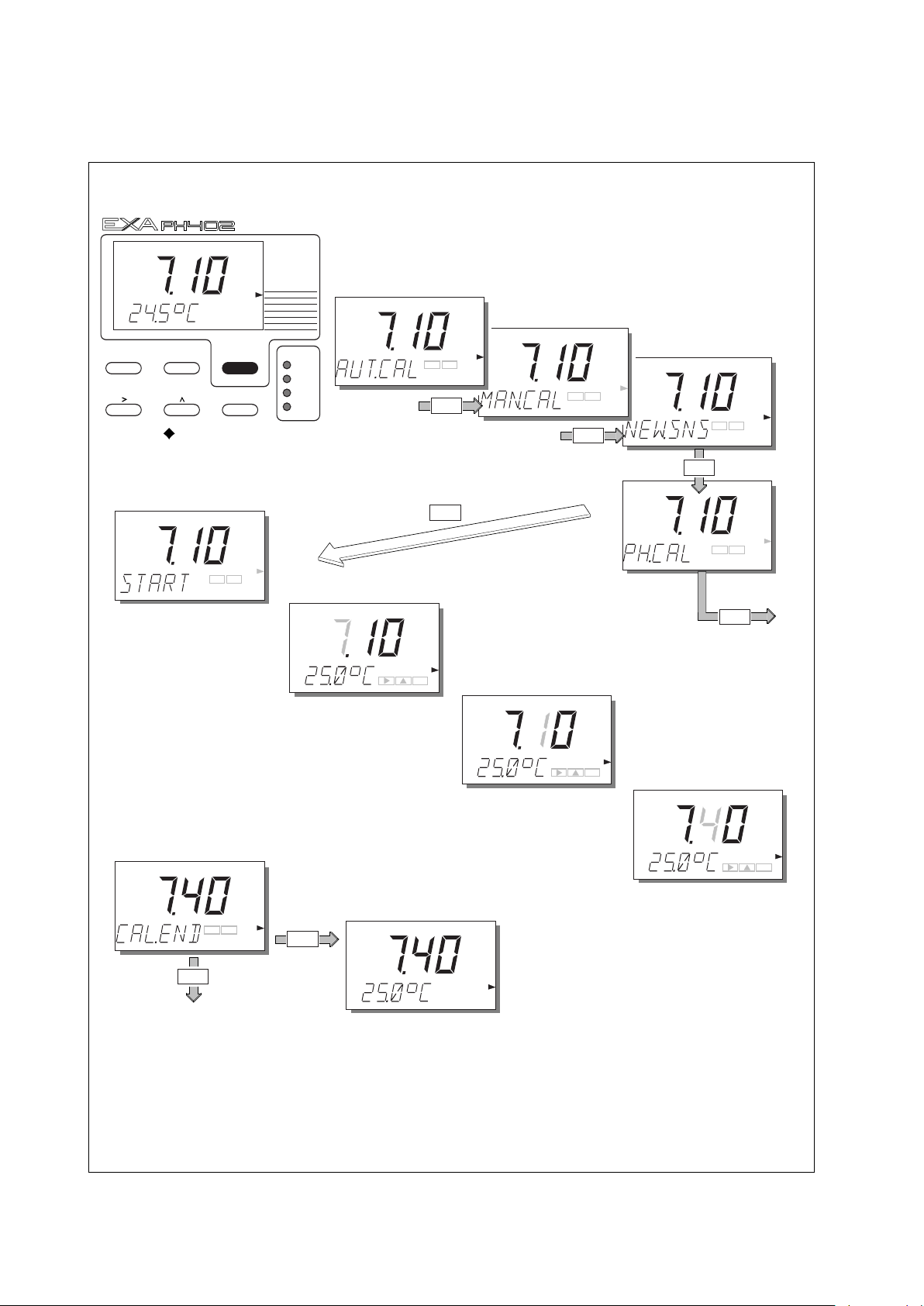
6-4 Calibration
p
H
N
O
Y
ES
p
H
N
O
Y
ES
Y
ES
NO
N
O
YES
pH
Y
ES
pH
pH
NO
Y
ES
E
NT
pH
pH
pH
pH
N
O
Y
ES
Put sensors in buffer
solution. Press YES.
Set the value
using the >, , ENT key.
Select the flashing digit with the > key.
Increase its value by pressing the key.
When the correct value is displayed, press ENT to enter the change.
>
>
MEASURE
MAN.CAL
DISPLAY
HOLD
NO MODEYES
ENT
YOKOGAWA
MODE
TEMPERATURE
A
UT.CAL
pH
C
ONTACTS
S1
S2
WASH/S3
FAIL/S4
12B6B3-24/a
pH
N
O
YES
Manual Calibration. (2nd parameter calibration) Press the MODE key. The legend AUT.CAL appears,
and the YES/NO key prompt flags flash. Press NO.
The display MAN.CAL appears.
Press YES to start calibration.
Press YES or NO at NEW.SNS prompt.
YES
NO
For 2 point (As Pot and Slope)
Adjustment select second buffer
solution and adjust as for pH7 buffer.
N
O
ENT
E
NT
YES
WAIT is displayed
briefly then EXA returns
to measuring mode.
6-5-3. Manual calibration (2nd parameter calibration)
IM 12B6B3-E-E
Page 69

YES
NO
YES
NO
Y
ES
N
O
pH
pH
ENT
YES
NO
pH
Y
ES
N
O
pH
NO
YES
Y
ES
N
O
ENT
YES
Adjust value
with >, , ENT Keys
>
YES
YES
Return to
measuring mode.
YES
YES
Return to
measuring mode.
Adjust value
with >, , ENT Keys
>
12B6B3-24/b
NO
Manual Calibration of
z
ero point according
to IEC 746-2
Manual Calibration of mV
o
ffset for ORP (2nd parameter).
Where both pH and ORP (or rH)
are measured, the offset (Asymmetry
potential) of the second parameter
i
s calibrated as shown below.
Calibration 6-5
IM 12B6B3-E-E
Page 70

6-6 Calibration
pH
N
O
Y
ES
N
O
Y
ES
pH
pH
pH
NO
Y
ES
MEASURE
MAN.CAL
D
ISPLAY
H
OLD
NO MODEYES
ENT
YOKOGAWA
MODE
TEMPERATURE
AUT.CAL
pH
C
ONTACTS
S1
S
2
W
ASH/S3
FAIL/S4
12B6B3-16
pH
N
O
Y
ES
Sample Calibration.
Press the MODE key. The legend AUT.CAL appears, and the YES/NO
key prompt flags flash. Press NO.
The display MAN.CAL appears.
Press YES to start calibration.
NO
Y
ES
N
O
YES
(Note: Press NO to start
calibration of zero point when
enabled in Service Mode).
Press YES at the same time as taking
sample for analysis.
PH402 now continues to measure/control,
as before. SAMPLE flashes to indicate that
data is stored waiting for input of analyzed
value.
6-5-4. Sample calibration
IM 12B6B3-E-E
Page 71

Calibration 6-7
pH
NO
Y
ES
pH
N
O
Y
ES
M
AN.CAL
YES
E
NT
pH
pH
N
O
Y
ES
YES
pH
NO
Y
ES
YES
MAN.CAL
pH
NO
YES
pH
Set the value
using the >, , ENT key.
Select the flashing digit with the > key.
Increase its value by pressing the key.
When the correct value is displayed,
press ENT to enter the change.
>
>
Press YES to return
to the measuring mode.
M
ODE
NO
pH
When the laboratory analysis is completed
the data is entered by first pressing MODE
Note: Display now
shows the same value
as at the time of taking
the sample.
Put sensors in buffer
solution. Press YES
.
ENT
YES
IM 12B6B3-E-E
Page 72

7-1 Maintenance
7. MAINTENANCE
7-1. Periodic maintenance for the EXA PH402 converter
The PH402 transmitter requires very little periodic maintenance. The housing is sealed to IP65 (NEMA 4X)
standards, and remains closed in normal operation. Users are required only to make sure the front window
is kept clean in order to permit a clear view of the display and allow proper operation of the pushbuttons. If
he window becomes soiled, clean it using a soft damp cloth or soft tissue. To deal with more stubborn
t
stains, a neutral detergent may be used.
NOTE:
Never used harsh chemicals or solvents . In the event that the window becomes heavily stained or
scratched, refer to the parts list (Chapter 9) for replacement part numbers.
When you must open the front cover and/or glands, make sure that the seals are clean and correctly fitted
when the unit is reassembled in order to maintain the housing’s weatherproof integrity against water and
water vapor
. The pH measurement uses high impedance sensors and may otherwise be prone to problems
caused by exposure of the circuitry to condensation.
The EXA instr
ument contains a lithium cell to support the clock function when the power is switched off.
This cell needs to be replaced at 5 yearly intervals (or when discharged). Contact your nearest Yokogawa
service centre for spare parts and instructions.
7-2. Periodic maintenance for the sensor system
NOTE:
Maintenance advice listed here is intentionally general in nature. Sensor maintenance is highly application
specific.
The sensor system must be kept clean to function well. This may require regular cleaning of the electrodes.
(The effect of dirty electrodes will be to slow the system response and perhaps corrupt the measuring loop
entirely). The frequency of cleaning and the method of cleaning will depend entirely on the process.
Where a refillable (flowing electrolyte) reference system is employed, make sure that the reservoir is kept
topped up. The rate of electrolyte consumption will again be process dependent, so experience will show
how often you must r
efill.
The periodic recalibration of the sensor system is necessary to ensure best accuracy. This takes into
account the aging of the sensors, and the nonr
ecoverable changes that take place. These processes are
slow, however. If frequent recalibration is needed, it is usually because the cleaning process is not effective,
the calibration is not well executed or the pH readings are temperature dependent. Monthly calibrations
should be sufficient for most applications.
If a film remains on the pH sensor after cleaning, or if the reference junction is partly plugged, then
measuring errors can be interpreted as a need for recalibration. Because these changes are reversible with
correct cleaning and/or proper selection or adjustment of the electrolyte flow through the junction, make
sure that these items are correct before recalibrating the system.
IM 12B6B3-E-E
Page 73

Maintenance 7-2
Calibration procedures are described in step-by-step detail in chapter 6. However, follow these guidelines.
1. Before starting a calibration, make sure the electrode system is properly cleaned so that electrodes are
fully functional. They must then be rinsed with clean water to avoid contamination of the calibration
solution.
2. Always use fresh buffer solutions to avoid the possibility of introducing errors from contaminated or aged
olutions. Buffers supplied as liquids have a limited shelf life, especially alkaline buffers which absorb
s
CO2 from the air.
3. Yokogawa strongly recommends NIST (primary) buffer standards in order to ensure the best accuracy
and best buffer capacity is available. Commercially adjusted buffers (e.g. 7.00, 9.00 or 10.00pH) are a
compromise as a standard, and are often supplied without the temperature dependency curve. Their
stability will be much worse than for NIST solutions.
NOTE:
NIST (formerly NBS) buffers are available as consumable items from any Yokogawa sales office under the
following part numbers:
6C232 4.01 pH at 25°C}
6C237 6.87 pH at 25°C} A box contains 5 packets of powder. Each makes a 200 ml solution.
6C236
9.18 pH at 25°C}
6C231 6C232 6C234 6C236 6C237
IM 12B6B3-E-E
Page 74

8-1 Troubleshooting
8. TROUBLESHOOTING
The EXA PH402 is a microprocessor-based analyzer that performs continuous self-diagnostics to verify that
it is working correctly. Error messages resulting from faults in the microprocessor systems itself are few.
Incorrect programming by the user can be corrected according to the limits set in the following text.
n addition, the EXA PH402 also checks the electrodes to establish whether they are still functioning within
I
specified limits. The transmitter checks the glass-electrode impedance for a low value to determine if it is
broken or cracked, and for a high impedance to check for internal breakage or disconnection.
The reference system is prone to more faults than the glass electrode in general. The unit measures the
impedance value and compares it to the programmed value in memory to determine acceptance during
testing. A high impedance signals pollution or poisoning of the reference electrode diaphragm.
Also, the EXA PH402 checks the electrodes during calibration to determine if the reaction time is suitable for
pH measurement. A specially timed check can be activated following each cleaning cycle. After calibration,
the unit checks the calculated asymmetry potential and the slope to determine if they are still within limits
specified by the software.
The slow shift of asymmetry potential could signal a poisoning of the reference electrode system by the
process. The decrease of slope equals a decrease of sensitivity of the glass electrode or can show a
coating buildup at the electr
ode.
The EXA PH402 makes a distinction among diagnostic findings. All errors are signaled by the FAIL area in
the display. Only faults in the measuring circuits activate the FAIL contact switching.
What follows is a brief outline of some of the EXA PH402 troubleshooting procedures, followed by a
detailed table of error codes with possible causes and remedies.
NOTE:
The diagnostic function of the PH402 gives a variable time interval between impedance checks, up to 5
minutes. When trouble shooting, a manual impedance check can be initiated by following the procedure in
section 5-1-6.
IM 12B6B3-E-E
Page 75

Troubleshooting 8-2
8-1. Diagnostics
8-1-1. Off-line calibration checks
The EXA PH402 transmitter incorporates a diagnostic check of the asymmetry potential after a calibration
has been completed. This is a valid check for both manual and automatic calibration routines.
he actual value can be called up from the DISPLAY routine in the maintenance menu. A large value often
T
indicates a poisoning or pollution of the reference system used. If the asymmetry potential exceeds
programmable limits, the EXA PH402 generates an error (E2).
The EXA PH402 also performs diagnostics to check for the slope of the pH electrode after automatic
calibration is completed. The actual value of the slope can be called up on the DISPLAY routine in the
maintenance menu (SL). This value is an indication of the age of the electrode. If the value stays within the
limits of 70 to 110 percent of the theoretical value (59.16 mV/pH at 25°C), it is accepted. Otherwise, the
unit generates an error (E3).
Activation or deactivation of the asymmetry diagnostic check and slope check is made from the Service
Codes. See Chapter 5 or Chapter 10 (Appendix).
8-1-2. On-line impedance checks
The EXA PH402 has a sophisticated impedance checking system. The sensors can be checked for their
impedance over a very wide range, which makes the tool equally useful for glass, enamel, reference and
metal (ORP) sensors. The measurement is temperature compensated for the characteristic of the pH glass
sensor.
In order to measure accurately over such a wide range, it is necessary to split the range into two. This is
done by a pair of jumper settings, high range and low range can be set on either input, making the system
extremely flexible.
The following error message table gives a list of problems that are indicated when the high or low
impedance limits are exceeded for a sensor. Such things as fouling, breakage and cable faults are readily
detected. The non-immersion of the sensors in the process fluid is also signalled.
IM 12B6B3-E-E
Page 76

-1 Spare parts
1
2
3
4
5
6
7
12
10
11
8
9
13
9
9. SPARE PARTS
able 9-1. Itemized parts list
T
Item No. Description Part no.
1 Cover assembly including gasket and 4 fixing screws (M4 x 20) K1541JG
2 * Digital / display board K1543DB
3 EPROM (programmed memory chip) + latest software K1543BK
4 Protective cover for power terminal complete with fixing screw K1541JH
5 * Input and power board (230 VAC) K1543PE
Input and power board (115 VAC) K1543PG
Input and power board (100 VAC) K1543PN
Input and power board (24 VDC) K1543PL
6 Fuse holder K1543AA
7 EXA 402 case K1541JJ
8 Fuse (box of 10 pieces) for 230 V AC (250 V AC, 50 mA, T) K1543AK
Fuse (box of 10 pieces) for 115 V AC and 100V AC (250 V AC, 100 mA, T) K1543AL
Fuse (box of 10 pieces) for 24 V DC (250 V AC, 1 A, T) K1543AM
9 Cable gland set (one gland including seal and backing nut) K1500AU
10 Flat cable K1543AB
11 Securing screw set K1543AC
12 Hingepin K1543KS
13 Lithium cell (battery) K1543AJ
14 RS485/232 Converter for communication to PC K1543WM
Options
/U Pipe and wall mounting hardware K1542KW
/PM Panel mounting hardware K1541KR
/SCT Stainless steel tag plate K1543ST
* NOTE: Contact your nearest Yokogawa service centre for the procedure for changing items 2 and 5.
(Re-initialisation of the instrument).
Fig. 9-1. Exploded view
IM 12B6B3-E-E
Page 77

10. APPENDIX
0-1. User setting table
1
FUNCTION SETTING DEFAULTS USER SETTINGS
Parameter specific functions
01 *PH.ORP 0 pH
02 *PRM2 0 Off
03 *Z1.CHK 1.1.1 High range, TC on
check on
04 *Z2.CHK 0.0.1 Low range, TC off
check on
05 *CAL.CK 1.1 AP on, Slope on
Temperature functions
10 *T.SENS 0 Pt1000
11 *T.UNIT 0 °C
12 *T.ADJ None
13 *T.COMP 0 Off
*T.COEF - 0.0 pH/10°C
Calibration functions
20 *∆t.SEC 5 Sec
*∆pH 0.02 pH
21 *AP.LOW -120 mV
*AP.HI 120 mV
22 *SL.LOW 70 %
*SL.HI 110 %
23 *ITP 7.00 pH
*SLOPE 100.0 %
*ASP.1D 0.0 mV
*ASP.mV mV
24 *BUF.ID 4 NIST 4
25 *BUF.ID 7 NIST 7
26 *BUF.ID 9 NIST 9
27 *ZERO,P 0 disabled
mA outputs
30 *mA 1.1 both 4-20mA
*OUTP.F 0.2 pH (ORP) & Temp.
31
*D/R 0 Reverse (control)
32 *BURN 0.0 both off
33 *RG.mA2 prop band only for PI control
*tI.mA2
34
35 *TABL1 21 pt table see code 31
36 *TABL2 21 pt table see code 31
integ. time
only for PI contr
ol
Appendix 10-1
IM 12B6B3-E-E
Page 78

10-2 Appendix
FUNCTION SETTING DEFAULTS USER SETTINGS
Contacts
40 *S1 2.0.0
41 *S2 1.0.0
42 *S3 4.0.0
43 *S4 4.0.0
44 *D.TIME 0.2 sec.
*PH.HYS 0.1 pH
45 *RANGE 1 pH
*PER 10 sec
*FREQ 70 p/min
46 *tI.CNT 100 sec
47 *EXPIR 0 off
*tE
User inter
50 *RET 1 on
51
52
53 *Err.4.1 1 hard fail
55 *CALL.M 0 250 days
56 *DISP 1 0.01 pH
Communication
60 *COMM. 0.1 off/write prot.
61
62 *PASS 0.0.0 all off
General
70
71 *tH.CHK 0 off
72
79
Test and setup mode
80
face
*MODE 0.0 both off
*PASS 0.0.0 all off
r.5.1 1 hard fail
*Er
r.4.2 1 hard fail
*Er
*Err.5.2 1 hard fail
*Err.07 1 hard fail
*Err.08 1 hard fail
*Err.09 1 hard fail
*Err.11 0 hard fail
*Err.16 0 hard fail
*Err.22 0 soft fail
*SOFT 0 LCD + Fail contact
*SET. 3.1 9600/odd
*ADDR. 00 00
*HOUR
*LOAD
. REV
*W
.D
*CUST
*TEST
15 min
set time
eset
r
0off
and date
defaults
IM 12B6B3-E-E
Page 79

Appendix 10-3
10-2. Configuration checklist for PH402G
Standard Configuration Options Reference for
change
Measured Variable(s)
primary inputs pH, ORP and Temp
pH range 0-14 pH any span within -2-16 pH "range"
pH range linearized disabled 21 point table codes 31& 35
ORP range -500 to 500 mV spans up to 3000mV between "range"
-1500 to 1500mV
Temperature range -30-140°C any span over 25°C "range"
Temperature unit Celsius Fahrenheit code 11
mA Outputs
analog output 4- 20 mA for pH 0- 20 mA or 4- 20 mA code 30
second output 4- 20 mA for Temp 0- 20 mA or 4- 20 mA code 30
output allocation pH and Temp pH, ORP, Temp, Table, PI cont code 31
output linearization disabled pH/ORP codes 35 & 36
Contact outputs
contact outputs
contact allocation pH & FAIL pH, temp, ORP, rH, code 40- 43
contact variables dead time= 0.2 s; hyst= 0.1pH time: 0- 200 s; hyst 0- 16 pH code 44
add. contact functions none time out alarm code 47
control functions none PI on contacts or mA output code 45, 46, 34, 33
digital Outputs none RS485 code 60
Communication
digital interface disabled RS485 code 60
communication software external PC402 contact factory
variables on display pH and temp pH, ORP, rH mA1, mA2, "display"
burn out disabled burn low (3.5)/ high (22) on mA1/ mA2 code 32
password protection disabled for maint/ comm./ serv level code 52
eturn return to measure in 10 min. enable or disable code 50
autor
add. functions in MAINT disabled wash start/ setpoints/ Imp. chk. start code 51
Diagnostics
impedance checking
check on calibration data active enable or disable code 05
check on stability 0.02 pH per 5 s choose stability level code 20
response check disabled enable or disable code 71
man. imp. check enabled manual start “maint”
Compatibility
pH or ORP glass sensor/metal electrode pH or ORP code 01
temperature sensor Pt 1000Ω Pt1000; Pt100, etc code 10
other sensors
2nd parameter disabled pH & ORP/ pH &rH code 02
manual temp. comp. disabled disable or enable "temp"
Special Features
fer table configuration
buf
temperature calibration none adjustment +/- 20 °C code 12
o point calibration
zer
sensor washing disabled interval 0.1 - 36 hours/time 0.1 - 10 min “wash”
call for maintenance set time interval 1 - 250 days code 55
HOLD during maintenance
contact during HOLD possible on S1, S2 or S3 code 40 - 42
process temp. compensation disabled set temperature coefficient code 13
soft fail alarm disabled possible for E1 .. E9, E12, E22 code 53
logbook
S1= high at 14 pH (4) freely programmable "setpoint"
S2= low at 0 pH code 40. 41, 42, 43
S3= WASH S4= FAIL
wash, PI control, HOLD, FAIL
SL, AP, Z1, Z2 etc.
active enable or disable code 03 & 04
enamel sensors (Pfaudler)
NIST standar
disabled disable or enable code 27
disabled
d
impedance check setup
fully configurable codes 24, 25 & 26
hold last or hold fix
2 x 50 events
codes 03 & 04
“hold”
code 61, 62
IM 12B6B3-E-E
Page 80

10-4 Appendix
10-3. Setup for sensor compatibility
10-3-1. General
The inputs of the EXA transmitter are freely programmable for ease of installation. Standard glass pH
electrodes, Ag/AgCl reference electrodes and Pt100 and Pt1000 temperature sensors need no special
programming. The EXA indicates a fault with a signal in the display field if there is a mismatch of sensors in
he connection.
t
10-3-2. Selection of measurement and reference electrode
The EXA PH402 is pre/programmed to accept industry standard glass electrodes and reference electrodes.
The unit initiates checks for asymmetry and slope during calibration. The on-line impedance checking
function has been upgraded in this most recent EXA release.
The EXA is universally compatible with all types of electrodes, such as enamel and antimony. In such
systems, however, the specific isothermal point of intersection (ITP), slope (pH/mV) and asymmetry potential
can be set for the type of electrode.
10-3-3. Selecting a temperature sensor
The EXA PH402 reaches its highest accuracy when used with the Pt1000 temperature sensor. This element
offers a 10-fold increase in resistance dependence over the Pt100 sensor. Choice of temperature sensor is
made in the Service Codes found in Chapter 5 and Chapter 10 (Appendix) of this manual.
l ITP
Most Yokogawa sensor systems use an Iso-thermal point (ITP) of pH7 and a zero point at pH7. This is
the default condition for which the transmitter is set. It is only necessary to consider this adjustment
when installing a system with a different ITP. Antimony systems and Pfaudler probes are good examples
of systems with different ITP values. Service code 23 is used. This also permits the setting of calibration
data for precalibrated sensors.
l Temperature sensor
The Pt 1000Ω RTD sensor is now becoming the most commonly used for temperature compensation.
The transmitter accepts inputs from several different temperature sensors to suit most sensor systems.
Service code 10-19 are used to set the temperature parameters and the process temperature
coefficient.
l Temperature calibration
For best accuracy, the temperature sensor should be calibrated to compensate for connection cable
ors. See Service code 12.
r
er
l pH Calibration
Traditionally, users select buffer solutions to suit the chosen output range. This is merely a continuation of
the days of analog instruments that used indicators driven by the mA output. With digital technology, it is
better to choose good buf
fer solutions and make an effective calibration than to use commercial
(adjusted) buffers which may have round number values, but are less effective buffers with lower buffer
capacity. It is for this reason that Yokogawa recommends that the NIST 4, 7 and 9 standard buffers be
used to calibrate solutions. The temperatur
24, 25, and 26 in the EXA PH402. Wher
e responses of these are pre-programmed into Service codes
e used with the semi-automatic calibration
e other buf
fers ar
function, their temperature response should be programmed into the relevant code.
IM 12B6B3-E-E
Page 81

Appendix 10-5
10-4. Setup for other functions
ontact Outputs
l C
Alarms, trips, and proportional control are all possible with the relay outputs, and configuration is by
Service codes 40-49. In addition, FAIL alarm and wash cycle controller are available.
l Current outputs
ransmission signals for the measured parameters and control signals can be set up in service codes 30
T
to 39.
l Wash cleaning
When used with the correct hardware, the EXA can control a wash cleaning system. Refer to service
codes 40, 71 and 72.
l Diagnostic Checks
Impedance checks, response time and stability checks are all included in the PH402. In order to get the
best performance from each of these features, the converter should be fine tuned according to
experience in the installation, and for the particular sensors selected. Service codes 3, 4, 5, 20 & 71 all
contribute to the diagnostics. Please note that the default settings provide an excellent starting point and
ovide most valuable information about the performance of the electrode system.
pr
l Communications
oprietary HART RS485 communication link allows remote configuration and data retrieval through
The pr
the PC402 communication package. This is an excellent tool for the maintenance engineer, quality
engineer or plant manager. Service codes 60-69 are used to set up the communications.
l Logbook
In combination with the communications link, a “logbook” is available to keep an electronic record of
events such as error messages, calibrations and programmed data changes. By reference to this log,
users can easily evaluate diagnostic information to determine predictive maintenance schedules. For
example, by monitoring the deterioration in the slope of the pH sensor, it can be changed before a failure
(or process shutdown) occurs.
IM 12B6B3-E-E
Page 82

10-6 Appendix
10-5. Set up for Pfaudler Type 18 sensor
The PH402 is intended to measure with all sorts of pH sensors, including the Pfaudler Type 18 sensor. The
Pfaudler design of dual membrane system uses two enamels of differing sensitivity. The first a pH sensitive
membrane, and the second one that responds to Na+and K+and acts as a reference.
he analyzer has dual high impedance inputs which measure perfectly even with very high impedance
T
sensors. However, the impedance measuring system (diagnostics) needs to be set up for best performance.
10-5-1. General set up
1. Set impedance measuring hardware. This is done by the use of links on the terminals adjacent to the
input terminals. For the Pfaudler system, this means that the terminals should have the links
disconnected in order to set for HIGH/HIGH impedance measuring.
2. Set the impedance check in software. Use codes 03 & 04 to enable the measurement and set for high
impedance and configure appropriate limits.
Code 03 set to 1.0.1 Iow limit 1 Megaohm
high limit 1 Gigaohm
Code 04 set to 1.0.1 Iowlimit 1 Megaohm
high limit 1 Gigaohm
3. Set the temperature compensation sensor as 100 Ohm Platinum RTD with service code 10.
Code 10 set to 1 100 Ohms Pt.
The system will now respond properly to the Pfaudler type 18 sensor, and the other functions of the EXA
analyzer will need to be set in the normal way to suit the use to which the loop is being put. Output ranges,
control functions and alarms should all be set as described elsewhere in this manual.
10-5-2. Calibration set up
The alter
4.
native Zero point (calibration and display) accor
ding to IEC 746-2 may be enabled in service
code 27, and set in the MAN.CAL routine. A value of 10.5 pH is a good starting point for the Pfaudler 18
sensor.
5. Where lab test data are available for the sensor, service code 23 can be used to set values for ITP &
Slope (and As pot for parameter 2 when enabled).
(This method can be useful for the type 18 sensor, as it is not usual to perform regular calibrations on this
system as with normal sensors. This is because the system may well respond differently, to ordinary buffers,
than with the process solutions. The procedure is to determine the temperature response (ITP) and the
sensitivity (Slope) of the sensor, and enter these values in code 23.)
Because this is a rather complex procedure, it is recommended instead to use the default settings of ITP =
7.00, and Slope = 100 %, and make a single point (MAN.CAL) calibration in the process at the working
temperature, and at the normal operating (control setpoint) pH. This ensures that the desired control point
will be measured accurately, even if there may be small deviations when there is a big deviation from the
setpoint. This of course has no effect on the accuracy of a control loop. The special construction of the
Pfaudler sensor ensures that there is practically no drift in the calibration. All that is necessary is to keep the
sensor membranes clean. This is best done by cleaning with low pressure steam, which restores the original
condition of the sensor, including the original calibration values.
IM 12B6B3-E-E
Page 83

Appendix 10-7
0-6. Software history
1
Software changes of the PH402
• Changes made by software release 1.1
- In the PH402 the limits for the impedance measurement can be set-up in service-code 3 and 4. When the
measured impedance value goes beyond these limits, an impedance to low/high error is generated and
he
t
Set-up limit value is displayed. More convenient is to measure beyond these limits and show the measured
value all the time.
• Changes made by software release 1.2
- When was function is started automatically, at the end of the wash function the question HOLD yes/no
was displayed and the instrument was waiting 10 minutes in HOLD. In release 1.2 the HOLD is
automatically switched off after the wash function is completed.
When the hardware limits for the impedance measurements are reached, the text Z1/2.LOW/HIGH is
displayed instead of displaying the limit value.
Reset problem during 3rd pH-buffer programming (SC26) is solved.
In case of pH device with second parameter ORP-measurement enabled (SC02), the instrument returned
with an inverted ORP value. Calculation updated in this release.
New temperature sensors are added (in combination with a future new analog board). Hence the
initialization procedure for PH402 is changed starting with software 1.2
• Changes made by software release 1.3
- Normally an E20 error indicates that programmed data is lost and no longer valid.
In software versions 1.0, 1.1 and 1.2 an E20 error might occur wrongly; the contents of the EEprom
is still correct.This error happened arbitrary just after starting up the PH402. The reason is a software
bug which is solved in version 1.3 .
The next features are added concerning mA1/2 output and contacts 1..4:
-mA2: PI control is now also available on ORP of 2nd parameter; this used to be available only for
rH.
-mA1: linear output on 2nd parameter is transferred from the menu of mA2 output to the menu of
mA1 output.
-Contacts 1..4:
alar
m is now also available on ORP of 2nd parameter; this used to be available only for rH.
PI control is now also available on ORP of 2nd parameter; this used to be available only for
rH.
After every wash cycle an impedance measurement will be performed now.
• Changes made by software release 1.4
- If something goes wrong during autocalibration or manual calibration, an E0, E1, E2 or E3 error will be
elease 1.3 and below, the error was set as a soft fail error which could only be
generated. In softwar
e r
cleared by a new, correct calibration. In version 1.4 the error is displayed as a message only; after
pressing the YES,NO or MODE key, the error message will be erased.
The rH calculation was wrong in version 1.3 and below, because of a polarity fault. In release 1.4 it has
been corrected.
- An E12 error indicates that the second process value (ORP/rH) exceeds its limits. In version 1.3 and
, the E12 er
below
In release 1.4, no E12 err
ror could be generated even when the second process value was disabled.
or will occur anymor
e if the second parameter is disabled.
- In release version 1.3 and below, scrolling through logbook was only available when pincode was
installed. In r
Upgrading of communication softwar
-
elease 1.4 logbook scrolling is always available, independent of pincode.
e.
IM 12B6B3-E-E
Page 84

10-8 Appendix
• Changes made by software release 1.5
n release 1.3 sometimes a spike on the current output occurs. The repetition rate is very low (each week
I
once or twice) and irregular. In release 1.5 this problem is solved.
REMARK: this new version is based on release 1.3 and therefore does not have the functionality of release
1.4.
• Changes made by software release 1.6
- In version 1.6 the new functions of 1.4 and 1.5 are combined.
• Changes made by software release 1.7
- The software version 1.7 for the PH402 is functional identical to the software version 1.6, only small
software changes for production improvement have been done.
• Changes made by software release 1.8
- The rH calculation was incorrect. There was a sign-error in the calculation formula. Also a 304mV offset
voltage has been added in the calculation to make it right for a modern sensor. The rH calculation is
correct now for a pH sensor with a buffer solution of pH 7 and an Ag/AgCl/KCl reference system. The
old calculation was based on a sensor with a buffer solution of pH 1 (with HCl reference system).
- The instrument locked up when entering a wrong password.
- When manual temperature is active and HIF is entered, the manual value is showed for all temperature
sensors.
- To improve EEPROM integrity the PEN (Program Enable) Pin is only enabled when there is an writecommand to the EEPROM
- Sample calibration is not correct when the Temp. Comp. <> 0. The offset due to the T.C. is wrongly
processed as a calibration correction.
• Changes made by software release 1.9
- Sensor check is switched OFF now during the start of CAL to prevent an unclear situation for the
customer.
• Changes made by software release 2.0
- Service code 79 added for loading all defaults except pH buffer tables.
- No longer PIN needed for PI, communication and logbook scrolling.
- Select in service code 53 to do/don’t toggle the failcontact periodically in case of a softfail.
- Default *T.COEFF changed from 0.00 into -0.00.
- 10k PTC added
elease 2.1
• Changes made by softwar
Bug fixed in configuring contact S4 as control contact.
-
Changes made by software release 2.2
•
e r
- E20 is cleared after the programmed data was recovered.
• Changes made by software release 2.3
- Prevent incorrect values in case open temperature input and manual temperature setting.
• Changes made by softwar
The maximum ORP span is set to 3000mV (was 2000mV).
-
• Changes made by software r
e release 3.0
elease 3.1
- Communication is enable as a factory default setting.
• Changes made by software release 3.2
- Added manual impedance check setting through HART command S1.
- Maximum value for high impedance setting raised to 2 GΩ.
IM 12B6B3-E-E
Page 85

Glossary
pH
mV
ITP
As pot
0 mV
0 ºC
10 ºC
25 ºC
12B6B3-12
ASYMMETRY POTENTIAL
mV
500
0
- 200
14
pH
ITP
Zero Point
0
7
GLOSSARY
pH (-log [H+] ) This is a logarithmic function of the Hydrogen ion activity (concentration). This
provides a quick indication of the acidic or alkaline behavior of a dilute solution.
Normally measured on a scale of 0-14 pH where low numerical values are acidic (0
is approximately 1 Normal acid) and high numbers are alkaline (14 is approximately
1 Normal NaOH). The neutral point is pH 7.
Defined by Nernst in the following equation: E = Eo + RT/nF x Ln [H+]
E
= measured potential
R = gas constant
T = absolute temperature
n = valence
F = Faraday number
Ln = Napierian logarithm
[H+] = activity of the Hydrogen ion
Eo = Reference potential
ORP Oxidation reduction potential is a measure of oxidizing power of a solution. The
greater the milliVolt value with a negative polarity, the greater the oxidizing power.
Reducing power is indicated by positive values of mV.
rH This is a composite value that indicates the oxidizing power of a solution
compensating for the influence of the acid or alkaline components. The scale is 055 rH, where oxidizing solutions provide the highest readings.
Asymmetry potential This is the difference between the isothermal point of intersection and the zero
point.
Slope This is the sensitivity of the pH electrode (mV/pH) usually expressed as a % of the
theoretical value (Nernst).
ITP This is the isothermal point of intersection. This is the value in pH at which the
temperature response of the system is at a null point. In other words, the point of
intersection of the temperature lines on a graph of millivolts vs pH. This point is
critical to the correct operation of the temperature compensation circuitry.
Zero point This is the value of pH at which the electrode combination yields 0 mV as an
output.
IM 12B6B3-E-E
Page 86

Error Codes
Code Error description Possible cause Suggested remedy
E0 Buffer solution temperature Buffer solution too hot or too cold Adjust buffer temperature
outside the range 0- 50°C Check cabling
E1 Measurement failed to stabilize . Sensors fouled Clean sensors
during the calibration Sensors too slow (aged sensor) Replace sensors
E2 Asymmetry potential too high. Sensors are aged or polluted Check buffer solution
(Limits set in service code 21.) Mistake in calibration Recalibrate at pH7
Replace sensor
E3 Slope (sensitivity) is outside limits. Measuring sensor aged Replace measuring sensor
(Limits set in service code 22.) Poor insulation at the connector Replace or dry cables
E4.1 Impedance of input 1 too low. Measuring sensor broken Replace measuring sensor
(Limits set in service code 03.) Damaged or damp connections Replace or dry cable
E4.2 Impedance of input 2 too low. Reference sensor broken Replace reference sensor
(Limits set in service code 04.) Damaged connections Replace cables
E5.1 Impedance of input 1 too high. Measuring sensor disconnected Check connections
(Limits set in service code 03.) Sensors not immersed in process Check process
Liquid earth disconnected Check connections
E5.2 Impedance of input 2 too high. Reference sensor fouled Clean or replace sensor
(Limits set in service code 04.) Liquid earth disconnected Check sensor immersion
Insuffiicent electrolyte Check electrolyte reservoir
E7 Measured temperature too high>140 °C Process too hot Check process
Wrong temperature sensor setting Check sensor & setting
Temperature sensor damaged Check connections
E8 Measured temperature too low <-30 °C Process too cold Check process
Wrong temperature sensor used Check sensor & setting
Temperature sensor damaged Check connections
E9 Measurement out of range (-2 to 16 pH) Sensors disconnected Check cabling
Sensor wrongly connected Check cabling
Sensor(s) defective Replace sensor(s)
E10 EEPROM write failure Fault in electronics Try again, if unsuccessful
contact Yokogawa
E11 Wash response time check failure. Measuring sensor aged Replace measuring sensor
Half-value recovery time too long. Sensor still coated after washing Check cleaning system
Defective wash system
E12 ORP / rH outside of preset limits Sensors disconnected or wrongly Check cabling
connected
No valid calibration data.
E14
esistance to temperature Cable resistance too high Use Pt1000Ω
Cable r
E15
sensor exceeds limits.
Call for maintenance interval time exceeded. System not maintained in Perform maintenance
E16
E17 Output span too small <1pH or <50 °C/°F Incorrect configuration by user Reprogram
Table values make no sense
E18
ogrammed values outside acceptable limits
Pr
E19
E20 All programmed data lost Fault in electronics Contact Yokogawa
or
Checksum er
E21
E22 Alarm activation time exceeded Process control not effective Check control equipment
opoint outside limits
Zer
E23
r
Data lost after switching fr
pH to ORP
oded contacts
r
Cor
Wrong sensor programmed Reprogram
eset time period
pr
ect configuration by user Reprogram
r
Incor
ery severe interference
V
Software problem Contact Yokogawa
within set time. Adjust value in code 47
Sensors ar
Mistake in calibration Recalibrate at pH7
e aged or polluted Check buffer solution
om
if needed adjust timings
Recalibrate
Clean and r
Reset inter
Replace sensor
eterminate
val
IM 12B6B3-E-E
Page 87

Radiumweg
Y
OKOGAW
A
Databankweg 20
3821 AL Amersfoort
The Netherlands
QIS 12B6B3-E
1st Edition May 1996
1. Introduction
This inspection procedure applies to the model PH402 microprocessor based converter. There is a serial
number, unique to the instrument which is stored in non-volatile memory. Each time the converter is powered
up, the serial number is shown in the display. An example is shown below:
Unique Number
025
F70.00
Line Number
ATE (automatic test equipment no.)
Month code
Year code
2. General
Final testing begins with a visual inspection of the unit to ensure that all the relevant parts are present and
correctly fitted.
3. Insulation Test
During the production testing procedures, the insulation is tested between terminal 3, the supply earth, and
power terminals 1 and 2. The test used applies the following criteria:
AC instruments - 2.1 kV DC, <1 mA, for >1 min.
DC instruments - 0.7 kV DC, <1 mA, for >1 min.
The outputs are also tested for isolation from earth
≥
10 MΩ.
4. Accuracy Testing
The automated checks in service code 80 are used in this procedure. This automatically sets the output
ranges to 0-14 pH and switches off the process temperature compensation. Temperature measurement is set
to display in °C. Calibration data are also reset to 100% slope and 0 mV As. Pot. (Note: all setting are restored
when the test mode 80 is completed.)
The test equipment needed is :
1. A resistance box of 0.1 Ω -100kΩ, accuracy 0.1% for temperature sensor simulation.
2. A 300 Ω resistor, accuracy 1% for mA output load resistor.
3. A millivolt source ranging from -1500 to +1500 mV with an accuracy of 0.1%.
4. A power supply to suit the converter (100 VAC, 115 /230 VAC or 24 VDC)
5. A mA meter with a range of 25 mA and an accuracy of 0.1% and a resolution of 1 µA.
6. A multimeter capable of measuring megohm ranges to check insulation impedance.
7. Screened cable to connect the input signals.
8. Single core flexible cable for liquid earth connection.
Quality
Inspection
Standard
EXA Series
Model PH402G
Converter for pH / ORP
IM 12B6B3-E-E
Page 88

Page 2 of 5
QIS 12B6B3-E
Connect the PH402 as shown in Fig. 1. The resistance decade box to terminals 11 with the screen to terminal
1
2 to simulate the temperature input. Set decade box to simulate 25 °C, see tables below for the value for the
selected sensor.
Connect the mV source to the input terminals, + (positive) to 15 with screen to 16, - (negative) to 13 with
screen to 17, link terminal 14 to the negative terminal of the mV source.
Connect the output terminals through the 300 Ω load resistor to the mA meter. (Note: current outputs may be
measured in turn with the same meter, or simultaneously if two meters and load resistors are available).
4.1 Power On
After switching on the power to the unit, 5 minutes should be allowed for warm-up, and to stabilise the
instrument completely before taking measurements.
4.2 Test Mode Entry
It is now necessary to proceed to ‘code 80’ in the service menu in order to check the calibration. See section 6
in the instruction manual
Press the button marked * (*SETP) appears in the lower display
Press NO (*RANGE) appears in the lower display
Press NO (*HOLD) appears in the lower display
Press NO (*WASH) appears in the lower display
Press NO (*SERV) appears in the lower display
Press YES (*CODE) appears in the lower display
Select code 80 and press ENT (*TEST) appears in the lower display
Press YES Go to test 4.3
4.3 Accuracy Test (ORP Display)
First set the mV source to the values listed below to simulate the ORP (mV) input and check the readings on
the display.
millivolt
s
ource
PH402
12
1
1
17
1
3
14
1
5
16
Resistance Box
mA
Meter
300 Ω
6
162636565
mA
Meter
300 Ω
1
2
3
AC DC
live
neutral
earth
Fig 1.
IM 12B6B3-E-E
Page 89

Page 3 of 5
QIS 12B6B3-E
Input Display Tolerance
Actual Display
*
1500 mV 1500 mV ± 1 mV 1501 mV
750 mV 750 mV ± 1 mV 750 mV
0mV 0mV ±1mV 0mV
-750 mV -750 mV ± 1 mV -749 mV
-1500 mV -1500 mV ± 1 mV -1500 mV
* figures in italics are typical values shown for example only.
Next vary the settings on the resistor decade box as listed below and check the temperature readings on the
second row of the display.
4.3.1 Accuracy Test (Temperature Display with Pt 100ΩΩΩΩ RTD)
Resistance Temperature Tolerance
Actual Display
*
92.2 Ω -20 °C±0.4°C -20.0°C
109.7 Ω 25 °C±0.4°C 25.1°C
129.0 Ω 75 °C±0.4°C 75.1°C
149.8 Ω 130 °C±0.4°C 130.0°C
4.3.2 Accuracy Test (Temperature Display with Pt1000 RTD)
Resistance Temperature Tolerance
Actual Display
*
921.6 Ω -20 °C±0.3°C -20.0°C
1097.4 Ω 25 °C±0.3°C 25.1°C
1290.0 Ω 75 °C±0.3°C 75.1°C
1498.3 Ω 130 °C±0.3°C 130.0°C
4.3.3 Accuracy Test (Temperature Display with 3kΩΩΩΩ Balco Sensor)
Resistance Temperature Tolerance
Actual Display
*
2406 Ω -20 °C±0.3°C -20.0°C
3000 Ω 25 °C±0.3°C 25.1°C
3660 Ω 75 °C±0.3°C 75.1°C
4386 Ω 130 °C±0.3°C 130.0°C
IM 12B6B3-E-E
Page 90

Page 4 of 5
QIS 12B6B3-E
4.3.4 Accuracy Test (Temperature Display with 5k1ΩΩΩΩ Sensor)
Resistance Temperature Tolerance
Actual Display
*
4273.8 Ω -20 °C±0.3°C -20.0°C
5100.0 Ω 25 °C±0.3°C 25.1°C
6018.0 Ω 75 °C±0.3°C 75.1°C
7027.8 Ω 130 °C±0.3°C 130.0°C
4.3.5 Accuracy Test (Temperature Display with 8k55Ω
Ω
Ω
Ω Sensor)
Resistance Temperature Tolerance
Actual Display
*
47000 Ω -10 °C±0.3°C -10.0°C
8550.0 Ω 25 °C±0.3°C 25.1°C
1263.0 Ω 75 °C±0.3°C 75.1°C
343.0 Ω 120 °C±0.3°C 119.9°C
4.3.6 Overall Accuracy Test
Still with the equipment setup as before, measure the current outputs with the following settings and confirm
agreement with the table below.
Input Display Tolerance Actual
Reading
*
Nominal mA
0-20 or 4-20
TolerancemAActual
mA1
*
Actual
mA2
*
414.1 mV 0.00 pH ± 0.01 pH 0.01 pH 0.00 4.00 ± 0.06 4.00 4.00
177.5 mV 4.00 pH ± 0.01 pH 4.01 pH 5.71 8.57 ± 0.06 5.72 8.58
0 mV 7.00 pH ± 0.01 pH 7.00 pH 10.00 12.00 ± 0.06 12.01 12.00
-177.5 mV 10.00 pH ± 0.01 pH 9.99 pH 14.29 15.43 ± 0.06 14.28 15.42
-414.1 mV 14.00 pH ± 0.01 pH 14.00 pH 20.00 20.00 ± 0.06 20.00 20.00
The tolerances specified relate to the performance of the PH402G in the controlled environment of the testing
facility. Production testing is carried out in combination with specially calibrated automatic test equipment
(ATE). In the field, the accuracy and linearity of the test equipment affects the error in the reading. As much as
an additional 0.1 mA may be seen in the mA output readings.
After completing these tests Press ENTER. This automatically starts the next test.
IM 12B6B3-E-E
Page 91

Page 5 of 5
QIS 12B6B3-E
5
. Accuracy & Linearity Check mA output circuits
This test is automatically generated in service code 80. Step through this test by repeatedly pressing ENTER.
Simulated Output
Tolerance
mA
Actual Output 1
mA
*
Actual output 2
mA
*
0.0 ± 0.02 0.00 0.00
4.0 ± 0.02 4.01 4.00
8.0 ± 0.02 8.01 8.01
12.0 ± 0.02 11.99 12.01
16.0 ± 0.02 16.01 15.99
20.0 ± 0.02 20.00 20.01
22.0 ± 0.02 22.01 21.99
This test is completed when the Display reads (*S1).
6. Relay Operation Check
This test is also automatically generated in service code 80.
> Key is used to select the relay to be tested. S1, S2, S3 or S4.
^ Key is used to toggle between ON /OFF states of the relay chosen.
ENT Key is used to exit this test mode.
Relay Number
Actual
*
S1 OK
S2 OK
S3 OK
S4 OK
7. Communication Check
Press ENT (*COMM) is displayed.
The PH402G generates a message to confirm function of the RS485 communication. Specialised equipment
is needed for this test. This test is not normally performed in the field.
Note
The testing of the PH402G is carried out under controlled environmental conditions. The end user may well find
that his ambient conditions vary considerably from the ones noted in this certificate. In this case it is necessary
to refer to the General Specification sheet for the details of ambient temperature drift etc.
*
Values in italics are shown for example only.
IM 12B6B3-E-E
Page 92

IM 12B6B3-E-E
Page 93
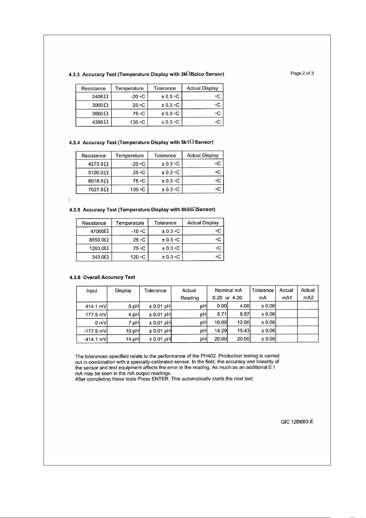
IM 12B6B3-E-E
Page 94

IM 12B6B3-E-E
Page 95

IM 12B6B3-E-E
Page 96

Y O KOGA WA
A HEADQUAR
W
YOKOGA
9-32, Nakacho 2-chome,
Musashinoshi
okyo 180
T
Japan
Tel. (81)-422-52-5535
Fax (81)-422-55-1202
E-mail: webinfo@mls.yokogawa.co.jp
www.yokogawa.com.jp
TERS
A CORPORA
W
YOKOGA
t Road
2 Dar
Newnan GA 30265
United States
el. (1)-770-253-7000
T
Fax (1)-770-251-2088
E-mail: info@yca.com
.yokogawa.com/us
www
TION OF AMERICA
okogawa has an extensive sales and
Y
distribution network.
Please refer to the European website
(www.yokogawa.com/eu) to contact your
esentative.
epr
est r
near
A EUROPE B.V
W
YOKOGA
Databankweg 20
3821 AL Amersfoor
The Netherlands
Tel. +31-33-4641 611
Fax +31-33-4641 610
E-mail: info@nl.yokogawa.com
www.yokogawa.com/eu
.
t
YOKOGAWA ELECTRIC ASIA Pte. Ltd.
5 Bedok South Road
Singapore 469270
Singapore
Tel. (65)-241-9933
Fax (65)-241-2606
E-mail: webinfo@yas.com.sg
www.yokogawa.com.sg
IM 12B6B3-E-E
Subject to change without notice Printed in The Netherlands, 08-504 (A) Q
Copyright ©
 Loading...