

Page 1
IM 12B6C2-E-H
6th edition
Instruction
Manual
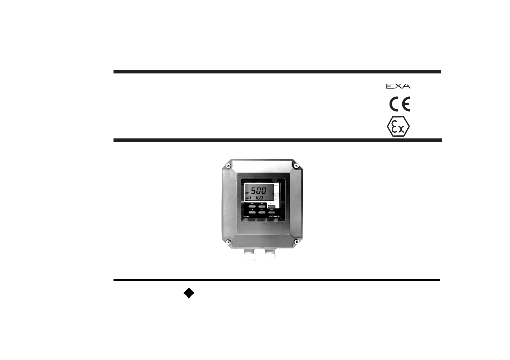
Model PH200
2-wire pH transmitter
YOKOGAWA
Page 2
FAIL
HOLD
MEASURE
AUT.CAL
MAN.CAL
DISPLAY
TEMP.
YES
NO
ENT
OUTPUT
SET HOLD
SERVICE
*
NO MODEYES
>
ENT>
MODE
TEMP.MAN
HOLD
pH
mV
OUTPUT HOLD
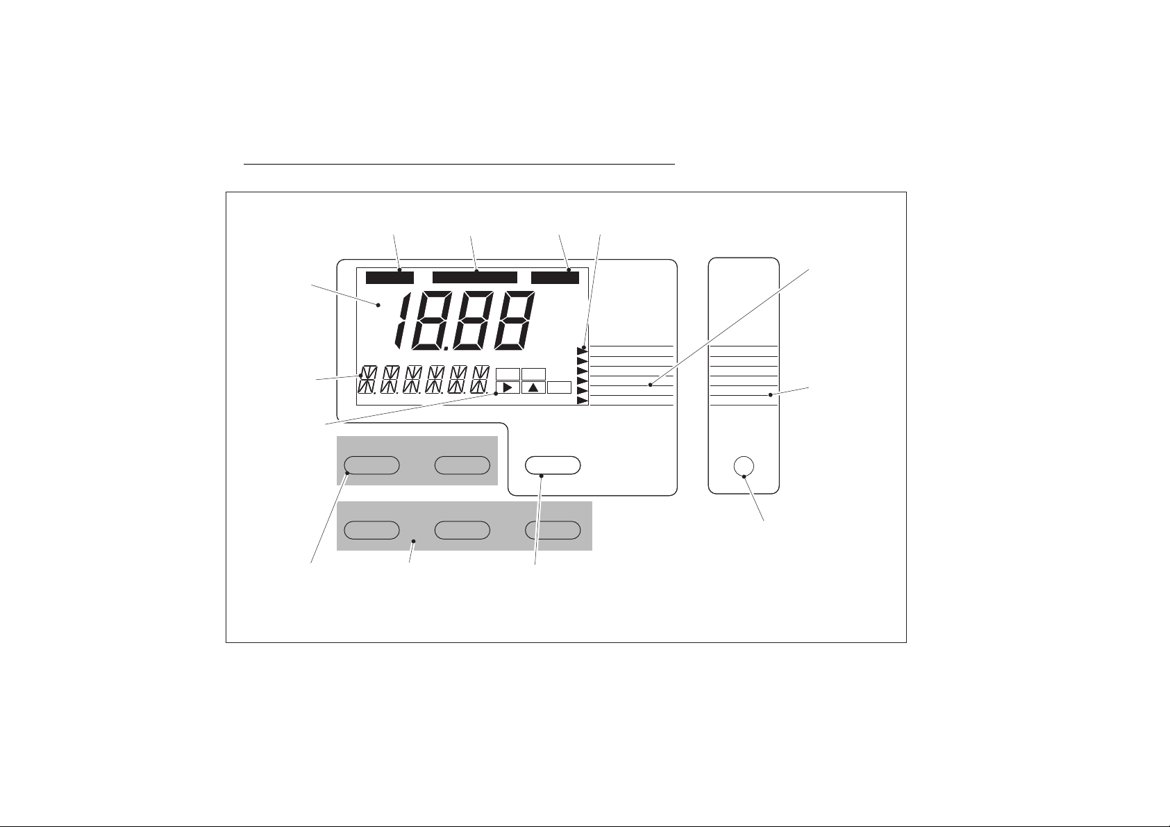
FLAG
MEASURED
VALUE DISPLAY
MESSAGE DISPLAY
KEY PROMPT FLAGS
SELECTION KEYS
YES : Accept setting
NO : Change to new setting
ADJUSTMENT KEYS
> : Choose digit for adjustment
^ : Adjust digit (to decrease pass
through zero)
ENT : Enter new value
NOTE: The first digit changes from 1, -1, - to blank
SELECT MODE
MEASURE/MAINTENANCE
Can be used to escape program at any
time
MANUAL TEMPERATURE
COMPENSATION FLAG
FAIL FLAG
MENU POINTER FLAGS
MENU FOR MAINTENANCE FUNCTIONS
(see chapter 5)
MENU FOR COMMISSIONING FUNCTIONS
(see chapter 4)
SELECT MODE
MEASURE/COMMISSIONING
IM 12B6C2-E-H
HOLD
pH
mV
TEMP.MAN
NO MODEYES
>
YES
FAIL
NO
ENT
MODE
MEASURE
AUT.CAL
MAN.CAL
DISPLAY
TEMP.
HOLD
ENT>
OUTPUT
SET HOLD
SERVICE
*
Page 3

IM 12B6C2-H-H
CONTENTS
1. INTRODUCTION..................................................................1
1-1. Application......................................................................1
1-2. Required components for pH measurement...................1
1-3. Identification ...................................................................1
2. TECHNICAL SPECIFICATIONS...........................................2
2-1. General specifications .....................................................2
2-2. Functional description .....................................................3
3. INSTALLATION AND WIRING .............................................4
3-1. Installation and dimensions.............................................4
3-1-1. Installation site ...................................................4
3-1-2. Mounting methods.............................................4
3-2. Wiring of sensors............................................................6
3-2-1. General precautions...........................................6
3-2-2. Additional precautions for installations in
hazardous areas ................................................6
3-2-3. Liquid earth........................................................6
3-2-4. Access to terminal and cable entry....................6
3-2-5. Connection diagram for sensors........................7
3-3. Wiring of power supply...................................................8
3-3-1. General precautions...........................................8
3-3-2. Additional precautions for installations in
hazardous areas ................................................8
3-3-3. Connection of the power supply........................8
3-3-4. Switching the instrument on...............................8
4. COMMISSIONING..............................................................11
4-1. Operations overview .....................................................11
4-2. Output range adjustment.....................OUTPUT...........12
4-3. Set up the HOLD function ...................SET HOLD ........14
4-4. Sensor selection and diagnostics..................................16
4-4-1. Selection of measurement and reference
electrode..........................................................16
4-4-2. Selecting a temperature sensor .......................16
4-4-3. Off-line calibration checks................................16
4-4-4. On-line impedance chacks ..............................16
5. MAINTENANCE..................................................................17
5-1. Automatic calibration...........................AUT.CAL...........18
5-2. Manual calibration ...............................MAN.CAL .........20
5-3. Selecting a value to display .................DISPLAY ...........22
5-4. Temperature compensation.................TEMP ...............24
5-5. Hold output function.....................................................26
6. TROUBLE SHOOTING .......................................................28
6-1. Introduction ..................................................................28
6-2. Error messages and explanation...................................29
Page 4

IM 12B6C2-E-H
7. SERVICE MODE.................................................................30
7-1. Introduction.................................................................30
7-2. Access to service settings...........................................31
7-3. Temperature function...................................................32
7-4. Temperature sensors...................................................32
7-5. Sensor checking..........................................................33
7-6. Display resolution ........................................................34
7-7. Signalling of fail condition ............................................34
7-8. Stabilization check .......................................................34
7-9. Auto return ..................................................................35
7-10.Buffer tables................................................................35
7-11.Temperature adjustment..............................................36
7-12. Manual adjustment of ITP, slope and
asymmetry potential....................................................36
7-13. Passwordprotection by three digit code......................37
7-14. Restore default settings ..............................................37
8. CLASSIFICATION...............................................................38
8-1. Cenelec........................................................................38
8-2. FM................................................................................39
9. CHANGE FROM PH TO ORP MEASUREMENT ..............40
9-1. How to change from pH measurement to
ORP measurement.......................................................40
9-2. Commissioning the transmitter .....................................40
9-3. Maintenance of the transmitter .....................................40
9-4. Special features............................................................40
9-5. Wiring diagram .............................................................41
9-6. Buffer values .................................................................41
APPENDIX A............................................................................42
Page 5

IM 12B6C2-E-H
1-1. Application
The EXA PH200 transmitter is a 2-wire pH
instrument intended to be used in industrial
installations in the field. For easy maintenance and operation it should be located close
to the sensors. It is powered from a remote
low voltage DC power supply through the 2wire connection. The EXA PH200 is compatible with most commercial available pH sensors and fitting systems.
The instrument is available in two versions:
- A general purpose version for use in safe
areas.
- An intrinsically safe version for use in
hazardous areas. The instrument can then
be installed in Zone 1 with the sensors in
Zone 1 or Zone 0.
The micro-processor is used in this instrument for continuous sensor diagnostics,
flexible on site commissioning and fine tuning by advanced functions.
In general a pH loop can be set up for different purposes:
- To be part of a total process control system
- To indicate dangerous limits of a process.
- To monitor product quality.
1-2. Required components for pH
measurement
1. A pH electrode and a reference electrode
or a combined pH-reference electrode.
2. A temperature sensor Pt100 (according
to IEC 751 or DIN) or Pt1000
3. A fitting for the above electrodes with
accessories
4. Signal cables with or without extension
boxes, etc.
5. The EXA PH200 2-wire transmitter with
mounting accessories for wall or pipe
mounting
6. A DC power supply (nominal 24 V DC)
with cabling and optional zener barriers
or an intrinsic safe power supply
7. Peripherals: e.g. strip-chart recorder,
panel indicator, PID-controller.
1-3. Identification
The instrument has an identification label,
which is fixed to the front plate.
This serves as a reference for the full model
code, power supply voltage and serial number. This label also carries authorised marks
to certify compliance with the current regulatory norms.
1
1. INTRODUCTION
MODEL
SERIAL NO.
SUPPLY
Page 6

2-1. General specifications
A. Intrinsic safety
– BASEEFA : Certified by and meets the require-
ments of EEx [ia] ib IIC T4 of CENELEC
Certificate nr. : 89C2379)
– FM : For IS CL1, DIV1, GP ABCD
T3B for TA-30 to 70 °C
T4 for TA-30 to 40 °C
Approval report: J.I. 1Y1A7.AX
– CSA : For Ex[ia] Class 1, Div. 1, Groups C
and D, T4A
Approval file: LR 102851-1
B. Indicating range :-1 to +15 pH.
C. Transmission signal : 4 - 20 mA DC; max. load 550 Ω
D. Transmission range : 0 - 14 pH.
User programmable to any range
with a minimum span of 1 unit.
E. Power supply
– Model PH200G : 17 - 40 V DC,
dependent on load
– Model PH200S : 17 - 31,5 V DC,
dependent on load
F. Climatic conditions
– Ambient temperature : -10 to +55 °C
– Storage temperature : -30 to +70 °C
– Relative humidity : 10 to 90%
– Weather protection : Rain and dust-tight IP65 (NEMA 4X)
G. Housing
– Material : Cast aluminium with chemical resi-
stant coating
– Window : Flexible poly-carbonate
– Colours : Moss green/off-white
– Cable glands : Polyamide
– Cable entries : Two
h
” glands
Hose connection optional
– Earth connection : For external ground
H. Mounting possibilities
– Surface mounting : Two M6 bolts, 9 mm length
– Wall/Pipe mounting : With optional mounting kit
– Sunlight protection : With optional hood
– Panel mounting : 154 x 172 octagonal with
30 mm corners (fixing with self-tap-
ping screws
I. Shipping details
– Dimensions : 162 x 178 x 115 mm
– Package : 225 x 225 x 220 mm
– Weight : ca. 2,5 kg
J. Safety and security
– Data protection : EEPROM memory
– Interference test : According IEC 801
– Power down : No affect, reset to measurement
2. TECHNICAL SPECIFICATIONS
IM 12B6C2-E-H
2
Page 7

IM 12B6C2-E-H
2-2. Functional description
The EXA PH200 is a real time micro-controller operated pH analysing system. It uses a
dedicated micro-controller with exclusively
developed software to control all functions
necessary in such a system. The input and
output functions are concentrated in the
analogue section of the instrument. Even
these functions are operated through special
interfaces designed to give a minimum of
interference problems to the digital functions. The digital and logic functions are
designed to operate securely. The unique
FAIL-function can give a warning when the
micro-controller has found a fault in the
measuring loop. This is accomplished by
sending a discrete 22 mA signal on the output. The micro-controller checks the working
of the analogue to digital input converter circuit and watches over the conversion to the
output signals. By using non-volatile memory
(EEPROM) for the essential in formation the
operating parameters are fixed in memory
without the need for a battery. The software
is designed with the user in mind. It uses a
simple step by step, question and answer
style to communicate with the operator by
giving messages on the second line of the
display and indicating which keys are to be
pressed in the display too.
The user-interface is limited to a basic set of
6 keys accessible through the flexible window cover. The keys are scanned continuously and actions are taken immediately.
An extensive system of checking va lues and
parameters is implemented in the software .
The 2-wire design gives maximum flexibility
of operation with other industrial instruments
and controlling systems. An intrinsically safe
version is available for hazardous areas. The
rugged housing is designed for outdoor use
(IP65). In addition it is shaped in a way that
indoor panel mounting is also possible. The
optional universal mounting kit includes
brackets for all mounting methods. The
commissioning of the instrument can be
performed on site or in advance. A three
level operating system keeps the approach
clear and distinguishes between every day
operation and maintenance against one time
operations like commissioning or fine-tuning.
All this makes the EXA PH200 operate like a
normal analogue transmitter with a number
of additional functions.
These extra functions are only possible by
using a micro-controller at the heart of the
system:
• Sensor checking durig measurement (1)
• Simplified calibration through a semiautomatic sequence.
• Additional process temperature compensation can be activated.
• Simple range adaptation making it a versatile instrument.
• Wide selection of temperature sensors.
• A HOLD-function for the output.
• Three buffer tables can be programmed.
• Programmable isothermal point of intersection.
• Protection against unauthorized access
by a passcode.
(1) European patent No. 0241601
US patent No. 4777444
3
Page 8
3. INSTALLATION AND WIRING
IM 12B6C2-E-H
3-1. Installation and dimensions
3-1-1. Installation site
As the transmitter is a rain-tight type it can
be installed outdoors as well as indoors. It
should, however, be installed as close as
possible to the sensors avoiding long cable
lengths between sensors and transmitter.
The certified version can be installed in
Zone 1.
Select an installation site where:
- mechanical vibrations and shocks are
negligible;
- no relay/power switches are in the direct
environment;
- the transmitter is not mounted in direct
sunlight and severe weather conditions;
- maintenance activities are possible (no
corrosive atmospheres).
The ambient temperature and humidity
should be within the limits of the specifications .
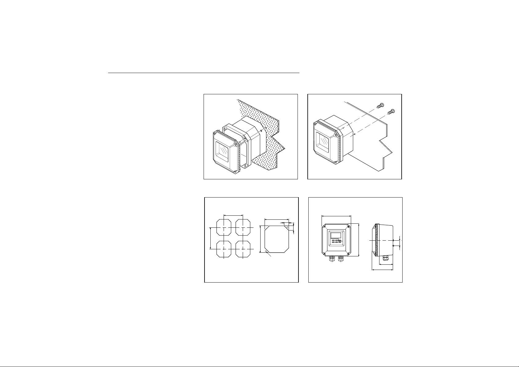
3-1-2. Mounting methods
The EXA PH200 transmitter has universal
mounting possibilities:
- panel mounting using selftapping screws
- surface mounting on a plate (by bolts
from the back)
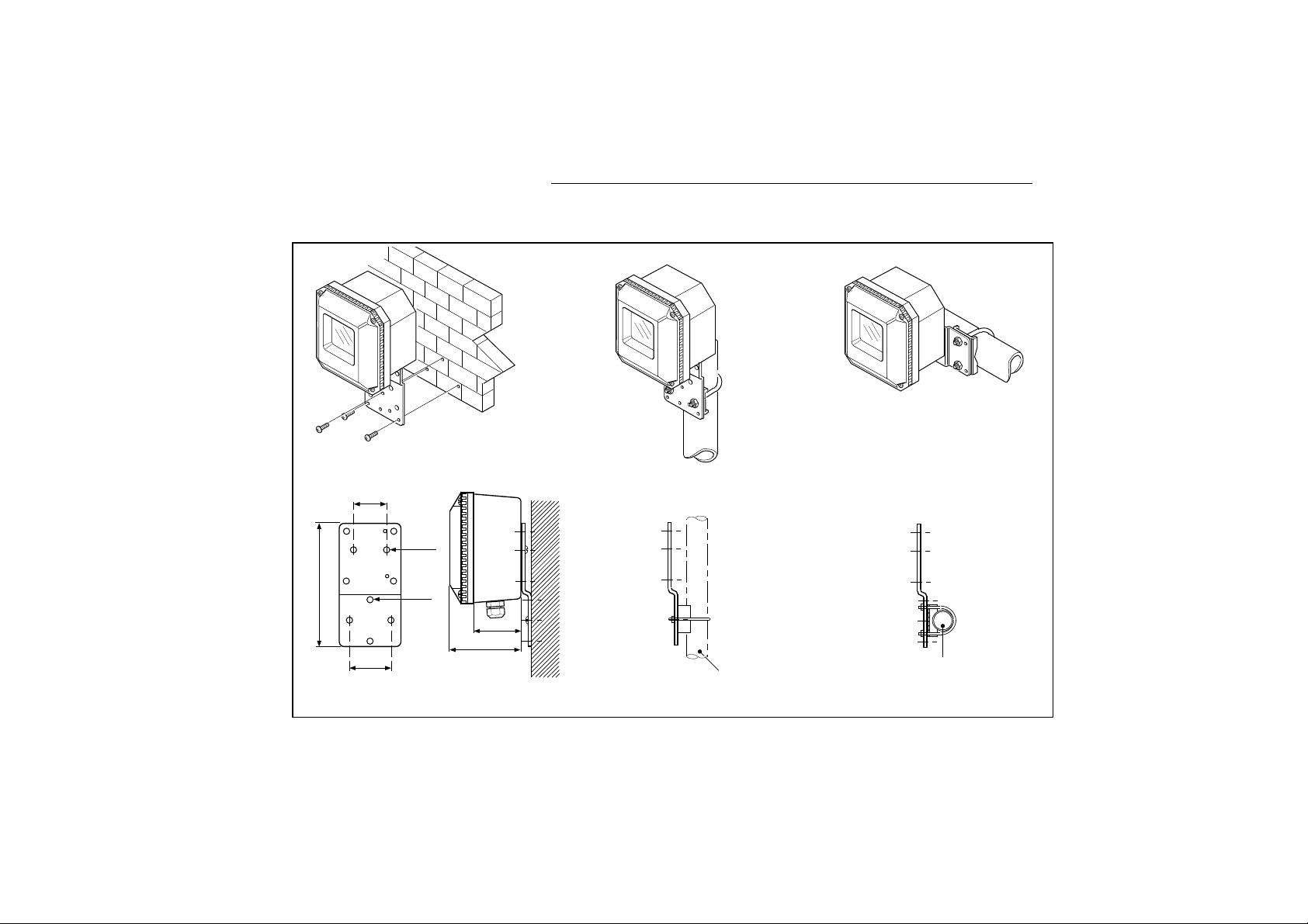
- wall mounting on a bracket (e.g. thick
brick wall);
- pipe mounting using a bracket on a horizontal or vertical pipe (maximum diameter 50 mm).
4
Panel mounting
Surface mounting
DimensionsCut-outs for panel mounting
2 x M6 (Screws)
Unit: mm (“)Unit: mm (“)
154 (6.06`)
162 (6.4)
180 (7)
77
115 (4.5)
30 1.2)
30 (1.18)
172(6.77)
2x ø4
min. 203 (8)
min. 229 (9)
Page 9
IM 12B6C2-E-H
5
Option /M: Universal wall/pipe mounting kit
Pipe mounting
(vertical)
Pipe mounting
(horizontal)
2” Pipe
2” Pipe
Wall mounting
115
(4.53)
70 (2.75)
56 (2.2)
200
(7.87)
2x ø6.6
(0.26)
4x ø10
(0.4)
77 (3.03)
Page 10

IM 12B6C2-E-H
3-2. Wiring of sensors
3-2-1. General precautions
Generally, transmission of signals from pH
sensors is at a very low voltage and high
impedance level. Thus a lot of care must be
taken to avoid interference. Before connecting sensor cables to the transmitter make
sure that next conditions are met:
– the sensor cables are not mounted in
tracks together with high voltage and or
power switching cables
– only standard coaxial electrode cables or
extension cable are used
– the transmitter is mounted within the dis-
tance of the sensor cables (max. 10 m)
– the setup is kept flexible for easy inser-
tion and retraction of the sensors in the
fitting.
3-2-2. Additional precautions for instal-
lations in hazardous areas
Make sure that the total of capacitances and
inductances connected to the input terminals of the EXA PH200 do not exceed the
limits given in the certificate.
This sets a limit to the cable and extensions
used.
– Grounding:
• If the sensors are mounted in a grounded
fitting, the external earth connection on
the left hand side of the transmitter must
be connected to "protective" earth.
• If the sensors are mounted in a fitting isolated to ground, it is recommended (not
required) to connect the earth connection
on the left hand side of the transmitter to
"protective" earth.
– The intrinsic safe version of the EXA
PH200 instrument can be erected in
Zone 1.
– The sensors can be installed in Zone 0 or
Zone 1 if a safety barrier according to the
limits given in the system certificate is
used.
3-2-3. Liquid earth
In all circumstances, the sensor side of the
measuring loop must be grounded to the
measuring liquid. The EXA PH200 uses
advanced differential high impedance input
circuits. This technique calls for a grounding
to the liquid. In addition to that the sensor
checking circuits also use the liquid earth for
measurement of impedance of the sensors.
All Yokogawa fittings have provisions for this
connection. It is usually called liquid earth in
all our manuals.
A separate connection should be made to
the terminal numbered 14 in all cases to get
a proper and stable measuring loop.
3-2-4. Access to terminal and cable
entry
1. To access terminals remove the front
cover of the EXA PH200 by releasing the
4 captive screws.
2. Thread the sensor cables into the connection space and connect the cables to
the terminals as indicated in the wiring
diagram. Make sure all connections are
firm and do not touch each other.
3. Screw the gland securely and tighten it to
keep out moisture. DO NOT use a
wrench to tighten the nut.
4. The optional hose connection is used to
guide the cables coming from an immersion fitting through a protective plastic
tubing to the transmitter.
6
Page 11
IM 12B6C2-E-H
7
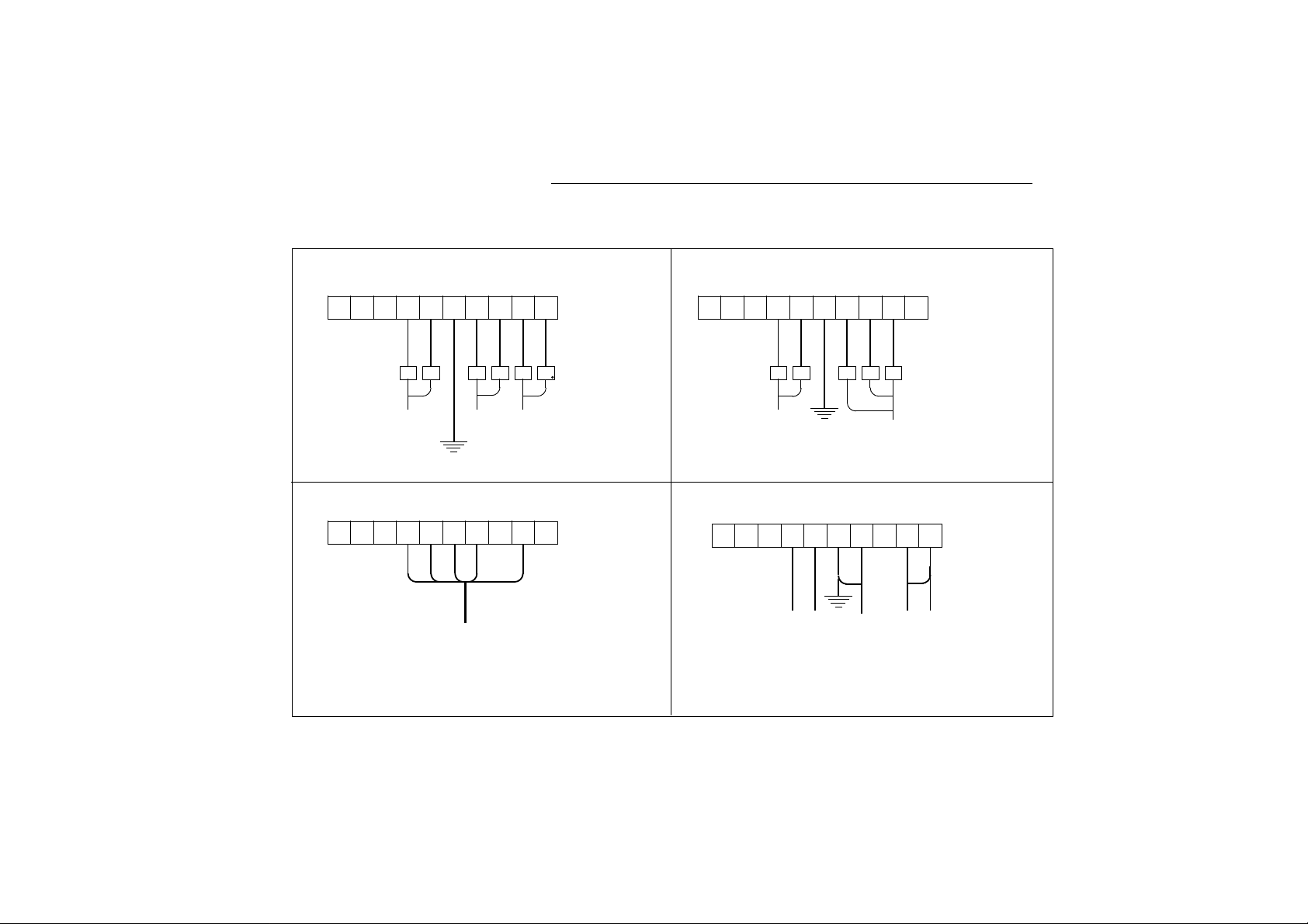
3-2-5. Connection diagram for sensors
+
-
G 11 12 14 13 17 15
16
Rd Bl Rd Bl Rd
Bl
+
-
G 11 12 14 13 17 15
16
Rd Bl Wt RdBl
+
-
G 11 12 14 13 17 15
16
+
-
G 11 12 14 13 17 15
16
T
1
T
2
SE RE GE S
Rd=Red, Bl=Blue, Wt=White,
Single electrodes
Temperature Combined
Liquid earth
Temperature - Reference pH
Pt 100 AgCl glass
(Pt 1000) (other) (other)
EXA compact and retractable electrodes
pH∑ Combined electrode
Combined electrodes
Liquid earth
Connect the numbered cable leads to the
corresponding terminals
Page 12

IM 12B6C2-E-H
3-3. Wiring of power supply
3-3-1. General precautions
Do not activate the power supply yet. First
make sure that the DC-power supply is
according to the specifications given.
WARNING: DO NOT USE ALTERNATING
CURRENT OR MAINS POWER SUPPLY! !
The cable leading to the distributor (power
supply) or safety barrier transports power to
and output signal from the transmitter. Use a
two conductor shielded cable with a size of
at least l.25 mm
2
and an outside diameter of
9 to 15 mm. The cable gland supplied with
the instrument accepts these diameters. The
maximum length of the cable is 2000 metre.
This ensures the minimum operating voltage
for the instrument.
3-3-2. Additional precautions for instal-
lation in hazardous areas
1. Ensure that the total of capacitances and
inductances connected to the terminals
of the EXA PH200 do not exceed the
limits given in the certificate of the safety
barrier or distributor.
2. The cable used should preferably have a
BLUE colour or marking on the outside.
3. Grounding:
• If the transmitter is mounted on a
grounded surface (e.g. a metal frame
fixed in the soil) the shield of the 2-wire
cable may NOT be connected to
ground at the distributor.
• If the transmitter is mounted on a non-
conducting surface (e.g. a brick wall) it
is recommended to ground the shield
of the 2-wire cable at the distributor
end.
4. Installation for EEx ia (sensors in Zone 0
or 1):
Generally, the distributor with input/output isolation has no external earth connection. If there is an earth connection on
the distributor and the external connection of the transmitter is connected to
"protective" earth, the shield of the 2-wire
cable may NOT be connected to "protective" earth at the distributor too.
3-3-3. Connection of the power supply
The terminal strip is accessed as was
described in § 3-2-4. Use the left-hand
gland to insert the 2-wire cable to the transmitter. Connect the supply to the terminals
mar ked +, - and G as is indicated in the
figures on pages 9 & 10.
3-3-4. Switching the instrument on
After all connections are made and checked,
the power can be switched on from the distributor. Observe the correct activation of the
instrument at the display. If for any reason
the display does not indicate a value, consult the trouble shooting section.
8
Page 13
IM 12B6C2-E-H
Dependance of load to supply voltage
9
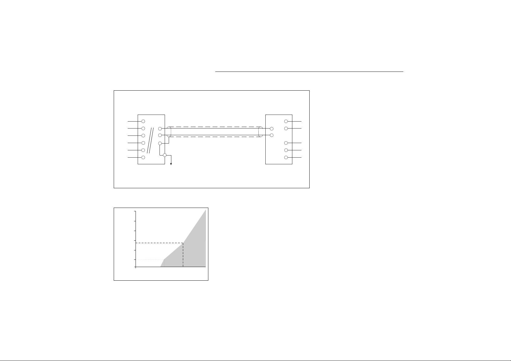
Wiring diagrams for power supply
General purpose design
pH-transmitter
EXA PH200G
Sensor
Distributor
Output
Supply
NOTE:
The outside earth terminal should be connected to site ground by a large area conductor (e.g. a flat earth strip) for
best protection against interference.
1200
1000
800
600
400
200
0
1718 20 24 40
Ohm
550
Supply voltage (V)
Load resistance (Ω)
+
–
+
–
G
Page 14
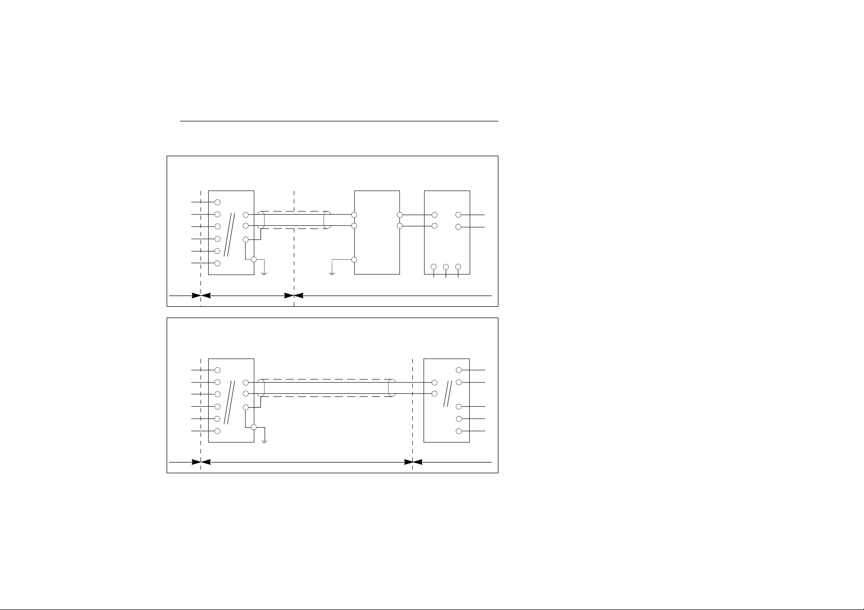
Wiring diagrams for hazardous areas
IM 12B6C2-E-H
10
Intrinsically safe design
(CELENEC standard EEX ib [ia] IIC T4)
pH-transmitter
EXA PH200S
Intrinsically safe design
(CELENEC standard EEX ib [ia] IIC T4)
pH-transmitter
EXA PH200S
EEx ib
Certified safety barrier
EEx ib
Certified distributor with
input/output isolation
Electronic current
limiting barrier
Vmax: 31.5 V
lmax: 35 mA
Pmax: 1,1 W
Zenerbarrier with
resistor
Vmax: 28 V
lmax: 93.3 mA
Pmax: 0.66 W
Shunt zener barrier or
supply unit or
isolated repeater
Vmax: 22 V
Imax: 85 mA
Sensor
Distributor
Output
Supply
Sensor
Output
Supply
Protective earthProtective earth
Protective earth
Hazardous area Safe area
Zone 0 or 1 Zone 1
Hazardous area Safe area
Zone 0 or 1 Zone 1
+
–
+
–
G
+
–
+
–
G
Page 15

IM 12B6C2-E-H
4-1. Operations overview
NOTE: All 3 levels can be separately protected by a password (see §7-13).
11
4. COMMISSIONING
Routine Use Chapter
MAINTENANCE AUT.CAL Calibration with buffer solutions 5-1
Operation by keys through MAN.CAL Calibration in process 5-2
closed cover DISPLAY Show or fix additional values 5-3
TEMP Select automatic or manual
temperature compensation 5-4
HOLD Switch HOLD-function on/off 5-5
COMMISSIONING OUTPUT Adjusting the output function 4-2
Operation by *-key when SET HOLD Activating the HOLD-function 4-3
cover is removed
SERVICE SERVICE Finetuning the performance 7
Operation by coded entry
from commissioning
Page 16

1. Access output
Remove cover by releasing 4 screws.
Access to commissioning menu
Select output function
Select OUTP
Confirm selection
2. Adjust low span value
Display will show *4 mA
Adjust value for low span
Select digit to adjust
Adjust digit
Confirm adjusted value
3. Adjust high span value
Display will show *20 mA
Adjust value for high span
Select digit to adjust
Adjust digit
Confirm adjusted value
Return to measurement
4-2. Output range adjustment
YES
ENT
>
^
ENT
MODE
>
^
NO
IM 12B6C2-E-H
12
ESCAPE TO MEASURE can be used at any stage to abort operation.
WARNING: If the HOLD function is activated the instrument returns with the question HOLD (flashing); answer YES or NO or
MODE again to return to measurement.
x
MODE
OUTPUT
SET HOLD
SERVICE
YES
NO
YES
NO
MODE
*
YES
NO
MODE
pH
OUTPUT
SET HOLD
SERVICE
ENT
YES
NO
MODE
OUTPUT
SET HOLD
SERVICE
ENT
Page 17

IM 12B6C2-E-H
1. What is the Output-range?
The display will always show the actual value
between -1 and 15 pH.
The output range is a linear function of mA
versus pH and is fixed by two points.
As the output is fixed to 4..20 mA the two
points of the linear function have to be programmed to set the range.
The factory setting is a full range of 0..14pH.
Any value between -1.. + 15 pH is acceptable for both points. A minimum span of 1
unit must be kept.
An error E19 will point to not acceptable
values.
NOTE:
1. The linear output signal is limited to 3.9 to
20.5 mA giving a safety area of 2.5% at
both ends.
2. Values below 3.9 or above 20.5 mA are
not related to input values and signal a
malfunction.
2. How to adjust?
EXAMPLE:
The EXA PH200 has to be programmed for
a range of 2 ... 12 pH.
Adjust 4 mA to 2.00 pH
Adjust 20 mA to 12.00 pH
The instrument will now correct its calculation for the output signal accordingly.
3. Calculation example
The current to be set at the output is calculated as follows:
pH - pH
min
mA = x 16 + 4
pH
max - pHmin
pH = actual value
pH
min
= value at 4 mA
pH
max
= value at 20 mA
pH
max
- pHmin = span (≥ 1 pH)
It is advisable to choose a span devisable by
10, 5 or 2 for easy reading on scales.
4. Other possibilities
Set a 22 mA signal on the output, when
FAIL is on (see §7-7).
13
4-2. Output range adjustment
Page 18

4-3. Set up the HOLD-function
IM 12B6C2-E-H
1. Access to HOLD-function
Remove cover by releasing 4 screws.
Push this key to select
Commissioning mode
Select HOLD
Move pointer to SET HOLD
HOLD = HOLD-function
Confirm selection
2. Activate HOLD-function
Display shows actual status
*H.OFF = HOLD not active
*H.ON = HOLD activated
Activate (deactivate) HOLD
Changing setting
Confirm setting
*H.FIX = HOLD fixed value
*H.LST = HOLD last value
Select HOLD fixed or last
Change selection
Confirm selection
3. Select value to hold
Display shows current setting
Adjust fixed value
Select digit to adjust
Adjust value of digit
Confirm setting
Return to measurement
14
OUTPUT
SET HOLD
SERVICE
YES
NO
YES
NO
MODE
*
.
YES
ENT
>
^
NO
YES
NO
YES
NO
x
ESCAPE TO MEASURE can be used at any stage to abort operation.
WARNING: If the HOLD function is activated the instrument returns with the question HOLD (flashing); answer YES or NO or
MODE again to return to measurement.
MODE
MODE
YES
NO
YES
NO
MODE
OUTPUT
SET HOLD
SERVICE
*
.
YES
NO
MODE
OUTPUT
SET HOLD
SERVICE
ENT
Page 19

IM 12B6C2-E-H
1. What is HOLD?
HOLD is a function freezing the output signal
temporary, during normal maintenance, preventing all sorts of alarming situations to
occur.
Two possibilities are generally used:
a. Keeping the output at the LAST value
just before the start of maintenance. This
should be used when recording and not
controlling instruments are connected to
the output signal.
b. Keep the output at a preset FIXED value
which will not cause any of the alarms to
go off or any controlling action to be
taken. This is the preferred situation
when dealing with pH-control systems.
2. How does it work?
The HOLD-function has to be activated from
the commissioning menu before it can be
used.
The EXA PH200 will keep the output frozen
during the following events:
a. Access to the commissioning menu.
b. Access to either of the calibration modes.
c. Switching it from the maintenance menu.
HOLD is signalled in the display by a special
flag.
The operator is prompted to switch HOLD
on or off before returning to nor mal measurement.
3. Example
In a neutralization set-up with both acid and
base dosing systems the neutral value is pH
7.00.
Activate the HOLD function and choose the
FlXed output value.
The span was set for 2-12 pH (see §4-2).
Thus pH 7.00 = 12 mA. Adjust the preset
value for the output at 12 mA.
During maintenance the output will be at 12
mA = pH 7.00 and no acid or base will be
pumped.
4. Auto return
Hold can be de-activated after 10 minutes if
no key is pressed. To cancel this function
(see §7-9).
15
4-3. Set up the HOLD-function
Page 20

IM 12B6C2-E-H
4-4. Sensor selection and diagnostics
The inputs of the EXA PH200 transmitter are
free programmable for ease of retrofit on
existing installation. Standard glass pH-electrodes, Ag/AgCI reference electrodes and
Pt100 sensor need no programming. If there
is a mismatch of the sensors connected a
fault will be indicated with a signal field on
the display and if activated by a 22 mA
signal.
4-4-1. Selection of measurement and
reference electrode
The EXA PH200 is preprogramed to ac-cept
industry standard glass electrodes and reference electrodes. Checks for asymmetrypotential and slope are implemented during
calibration. The on-line impedance check on
both sensors is not initialized unless activated from the service level §7-5. The EXA is
suitable for all type of electrodes (e.g.
Enamel, Antimony). In §7-3 the specific
Isothermal point of intersection (ITP), slope
(pH/mV) and asymmetry potential can be set
for each type of electrode.
4-4-2. Selecting a temperature sensor
The EXA PH200 has been factory set for a
Pt100 temperature sensor to DIN standards.
This will give satisfactory results when the
normal electrode cable length is used. To
correct for cable resistance it is possible to
calibrate the sensor from the service level
(zie §7-11).
The highest accuracy is obtained by using a
Pt1000 element with the EXA PH200 transmitter. This element gives a ten-fold increase
in resistance dependance over a Pt100 sensor. Setting the instrument for Pt1000 is
from the service level at §7-4.
4-4-3. Off-line calibration checks
The EXA PH200 transmitter incorporates a
checking of the asymmetry-potential after a
calibration has been performed. This is valid
for both manual or automatic calibration.
The actual value can be called up from the
display routine in the maintenance menu
(AS). A large value can indicate a poisoning
of the reference system used. If the asymmetry-potential exceeds + 120 mV or
-120 mV an error E2 will be generated.
To disable this checking see §7-5.
The EXA PH200 also checks for the slope of
the pH sensor after automatic calibration
has been performed. The actual value of the
slope can be called up from the display routine in the maintenance menu (SL). The
value is an indication for the "ageing" of the
sensor. If the value stays within the limits of
70 to 110 % of the theoretical value of
59.16 mV/pH at 25°C it is accepted.
Otherwise an error E3 is generated. Disable
this testing from the service level §7-5.
16
Page 21

IM 12B6C2-E-H
4-4-4. On-line impedance checks
The EXA PH200 transmitter is delivered from
the factory with an impedance check disabled. To activate this impedance checking
refer to §7-5. The impedance check works
on both measuring and reference electrode,
but not in the same way. The measuring
electrode is checked for presence of a high
impedance on the input side. An open circuit is signalled by an error E5. A short circuit is signalled by an error E4. The impedance of the reference electrode is measured (RZ). The actual value (in kilo Ohm) can
be called up from the display routine in the
maintenance menu. When pH is measured
in high purity water it is necessary to adjust
the reference impedance for the low conductivity of the solution. In general a high
impedance value can be related to a diaphragm clogging, fouling or non-immersion
of the sensors. If the value exceeds the limit
set an error E6 is generated. Activation and
limit setting (*IM.LMT) is done from the service level §7-5.
17
Page 22

1.Access automatic calibration
AUT.CAL = Automatic calibration
Access to maintenance mode
Select automatic calibration
Move pointer to AUT.CAL
Confirm selection
2. First buffer calibration
CAL 7 = Calibrate at pH 7
Select pH value for first buffer solution
Accept displayed buffer
Select other value
Calibration can be ended *
Continue calibration with second
buffer solution
End calibration with on buffer only
(asymmetry potential only)
3. Second buffer calibration
CAL 4 = Calibrate at pH 4.
Select pH value for second buffer solution
Accept displayed buffer
Select other value
Calibration can be ended *
End calibration
Repeat calibration with first buffer
solution
5. MAINTENANCE 5-1. Automatic calibration
IM 12B6C2-E-H
18
MEASURE
AUT.CAL
MAN.CAL
DISPLAY
TEMP.
HOLD
YES NO
YES NO
pH
MODE
ESCAPE TO MEASURE can be used at any stage to abort operation.
WARNING: If the HOLD function is activated the instrument returns with the question HOLD (flashing); answer YES or NO or
MODE again to return to measurement.
MODE
MODE
NO
YES
NO
YES
NO
YES
NO
YES
NO
YES
Insert electrodes in buffer solution. Display shows CAL and
flashes while instrument searches for stable measurement.
Display show CAL.END. Measurement is now stable.
*) The value shown on the display can deviate from the buffer value. This is fixed after calib-
ration is completed.
Insert electrodes in buffer solution. Display shows CAL and
flashes while instrument searches for stable measurement.
Display show CAL.END. Measurement is now stable.
YES NO
YES NO
MODE
MEASURE
AUT.CAL
MAN.CAL
DISPLAY
TEMP.
HOLD
YES NO
YES NO
MODE
MEASURE
AUT.CAL
MAN.CAL
DISPLAY
TEMP.
HOLD
Page 23

IM 12B6C2-E-H
1. What is automatic calibration?
Automatic calibration is the usual process of
calibrating a pH measuring loop with the aid
of two buffer solutions.
The first calibration is usually at pH 7; this is
to correct the asymmetry potential of sensors (zero).
The second calibration is most commonly
made at pH 4. This corrects the slope of the
sensors (sensitivity) . After this two point calibration the instrument is accurate to the
buffers used.
The EXA PH200 gives you the freedom to
use up to three buffer-solutions you want in
any sequence you like. The buffer solutions
can be programed in memory tables.
In the automatic calibration mode the instrument prompts the operator for the re quired
buffer solution, checks the signal for stable
conditions and then calibrates. The new calibration is then checked and a warning is
given if values are unacceptable.
During calibration the output will be frozen if
HOLD was activated.
2. How does it work?
A. The instrument asks for a buffer. Accept
or change
B. The sensor is immersed and checked for
stability
C. CAL.END, Stop or move on the second
calibration
D. Values acceptable or rejected.
E. After second calibration give YES to end
session.
NOTES:
1. It is not necessary to have the calibration
points within the measuring range of the
instrument, it is however advisable to do
so.
2. If no keys are pressed for 10 minutes
and the calibration was not finished the
instrument will return to measurement
with the old calibration values.
3. If HOLD was activated the instrument will
return to measurement after another 10
minutes.
Press YES to start the calibration. After sta-
bilization CAL.END will show. Press NO to
move on to pH 4.
3. Example
Standard calibration procedure.
Select AUT.CAL routine using MODE and
YES keys (enter pass code if necessary).
Select buffer pH 7using YES key.
Insert the rinsed sensors from the process
into a solution of pH 7.00 at 25°C.
CAL.END display on stable reading. Press
YES to end or NO to go on to next buffer.
Clean the sensor with water and insert into
buffer solution of pH 4.00 at 25°C.
CAL.END display on stable reading. Press
YES to end.
The whole process will not take more than
15 minutes and should be repeated at least
once every 2 months or whenever the EXA
PH200 signals a malfunction with an
ERROR-message .
4. Further possibilities
- Other buffer solutions than after 4, 7, 9.
- Using Special buffer tables for temperature
compensation (e.g. calibration in warm
buffers) §7-10.
19
5-1. Automatic calibration
Page 24

5-2. Manual calibration
IM 12B6C2-E-H
1. Access to manual calibration
MAN.CAL = Manual calibration
Access to maintenance mode
Select manual calibration
Move pointer to MAN.CAL
Confirm selection
2. Adjust value manually
Display shows measured value
START = Start manual calibration
Confirm start of adjustment (display frozen, ready for adjustment
to new value)
Adjust new value.
Adjust process value to previously determined value (e.g. from hand-held pH-meter)
Select digit to adjust
Adjust value
Confirm adjusted value
3. End calibration
CAL.END = End of calibration
End calibration
End calibration and return to
measurement
Continue routine to calibrate
second point when using buffer
solution (repeat step 2)
Error E02 or E19 indicate manual calibration
is not acceptable
20
MEASURE
AUT.CAL
MAN.CAL
DISPLAY
TEMP.
HOLD
YES NO
YES NO
MODE
E
ESCAPE TO MEASURE can be used at any stage to abort operation.
WARNING: If the HOLD function is activated the instrument returns with the question HOLD (flashing); answer YES or NO or
MODE again to return to measurement.
MODE
MODE
NO
YES
YES
ENT
>
^
YES
NO
YES NO
YES NO
MODE
MEASURE
AUT.CAL
MAN.CAL
DISPLAY
TEMP.
HOLD
MEASUR
AUT.CAL
MAN.CAL
DISPLAY
TEMP.
HOLD
YES
YES
NO
.
NO
MODE
Page 25

IM 12B6C2-E-H
1. What is manual calibration?
Manual calibration or process calibration is
the calibration executed with a freshly taken
sample from the process.
This sample is then measured with an off
line instrument and the value obtained is
programmed into the EXA PH200 transmitter.
Manual calibration can be used for calibrating the sensors with a buffer solution specially made for this purpose.
NOTE:
This routine can also be used to calibrate
with two points as an alternative to automatic calibration e.g. for occasional use of not
programed buffers.
2. How does it work?
1. Take a sample from the process.
2. Measure the pH with an off-line pH meter
which has been previously calibrated with
standard buffers and is equiped with an
automatic temperature compensation.
3. Adjust the value of the in-line EXA PH200
transmitter to the measured value.
4. Any values outside the normal operating
range of the instrument are signal led by
Error 19.
3. Example
The EXA PH200 indicates a process value of
pH 6.54 at 50°C.
A freshly calibrated portable pH-meter inserted into a hot sample reads 6.62 pH at
50°C.
The value is adjusted to the process value at
manual calibration to bring the values in
agreement.
A laboratory check of the same sample
shows the value to be pH 6.612 at 25°C.
The difference is due to the change of pH of
this particular sample with temperature.
21
5-2. Manual calibration
Page 26

1. Access display routine
DISP = Display routine
Access to maintenance mode
Select display
Move pointer to DISPLAY
Confirm selection
2. Read data
The second line of the display will show the
possibilities
Parameter Unit
Temperature °C
Output signal mA
Potential mV
AS Asymmetry mV
SL Slope %
RZ Impedance Ref. electrode kΩ
REL Software release
3. Reprogram data display
Move to desired value for diaplay
Confirm selection
Return to measurement
IM 12B6C2-E-H
22
5-3. Selecting a value to display
MEASURE
AUT.CAL
MAN.CAL
DISPLAY
TEMP.
HOLD
YES NO
YES NO
MODE
MODE
NO
YES
NO
YES
ESCAPE TO MEASURE can be used at any stage to abort operation.
WARNING: If the HOLD function is activated the instrument returns with the question HOLD (flashing); answer YES or NO or
MODE again to return to measurement.
MODE
MODE
YES NO
YES NO
MODE
MEASURE
AUT.CAL
MAN.CAL
DISPLAY
TEMP.
HOLD
YES NO
YES NO
MODE
MEASURE
AUT.CAL
MAN.CAL
DISPLAY
TEMP.
HOLD
Page 27

IM 12B6C2-E-H
1. What is the display routine?
The second line in the display is intended to
be used to:
– show actual status
– show messages
– show errors
When delivered from the factory the EXA
PH200 shows the temperature on the
second line.
You can make the instrument show a different parameter on the second line by selecting it from the list at the right.
2. What can you read?
Temperature actual value
Output signal actual value
Potential actual value
Asymmetry measured value
Slope measured value
Impedance actual value
Reference impedance is an actual value.
The choice of temperature units is done
from the Service level.
Reference impendance is shown to indicate
the status of the diaphragm of the reference
electrode. Glass electrode impedance is also
checked but not shown.
The release version is an indication for the
servicing of the instrument and cannot be
fixed in the display.
3. Example
To check the value of the output signal
(4...20 mA) it is displayed on the second
line.
Measuring range 2 - 12 pH
Ouptut signal 4 - 20 mA
Process value 8.5 pH
Output value 4.4 mA
When the second line is changed to display
output the current signal is visible all the
time.
Whenever HOLD is activated the value on
the display is frozen to the programmed
value (using the FIXED setting).
Pressing MODE will take you back to
measuring and the temperature will show
again.
4. Further possibilities
0.01 pH/0.1 pH display resolution.
(See §7-6).
23
5-3. Selecting a value to display
Page 28

5-4. Temperature compensation
IM 12B6C2-E-H
1. Access temperature compensation
TEMP = Temperature compensation
Access to maintenance mode
Select temperature compensation
Move pointer to TEMP
Confirm selection
2. Select automatic or manual temperature compensation
T.AUTO = Automatic temperature compen-
sation
T.MAN = Manual temperature compensa-
tion
Select automatic/manual compensation
Change displayed selection
Confirm selection
Adjustment of temperature
Only when manual is selected
Select digit to adjust
Adjust value
Confirm adjusted value
3. Setting the temperature coefficient *
COEFF = Temperature coefficient
pH change per 10°C
When the additional process compensation
has been commissioned from the service
level this menu will show.
Adjust solution temperature compensation
Select digit to adjust
Adjust value
Confirm adjusted value
* (only when process compensation was
activated in §7-3)
24
MEASURE
AUT.CAL
MAN.CAL
DISPLAY
TEMP.
HOLD
YES NO
YES NO
MODE
MODE
NO
YES
NO
YES
ENT
>
^
ENT
>
^
ESCAPE TO MEASURE can be used at any stage to abort operation.
WARNING: If the HOLD function is activated the instrument returns with the question HOLD (flashing); answer YES or NO or
MODE again to return to measurement.
MODE
YES NO
YES NO
MODE
MEASURE
AUT.CAL
MAN.CAL
DISPLAY
TEMP.
HOLD
MEASURE
AUT.CAL
MAN.CAL
DISPLAY
TEMP.
ENT
HOLD
YES NO
MODE
Page 29

IM 12B6C2-E-H
1. What is compensated for?
Temperature influences the sensitivity of the
glass electrode.
To nullify this effect the EXA PH200 has to
compensate the pH value with the formula
derived by Nernst.
To be able to do this the temperature has to
be measured as well. Either by a seperate
sensor or a temperature setting.
Temperature compensation can be set to
manual if the process is near pH 7 or at
fixed temperature.
2. How is it compensated?
The process temperature is measured with a
separate circuit connected to the temperature sensor (e.g. Pt1000 resis tor).
The resistance value of the temperature sensor is calculated into the temperature value.
This value is used to calculate the compensated value for the pH on the display.
3. Example
Setting the manual temperature compen
sation to a fixed setting of 30°C.
Press NO to change from default automatic
compensation to manual compensation.
The display will show TEMP °C and the
value can be adjusted to 30°C. Press ENT
to confirm the setting.
The display will show TEMP.MAN at the top
to indicate your choice.
4. Further Options
- Process temperature compensation (see
Service settings §7-3).
- Calibrating the temperature circuit (see
Service settings § 7-11).
25
5-4. Temperature compensation
Page 30

5-5. Hold output function
IM 12B6C2-E-H
1. Access HOLD
NOTE:
This function can only be used if activated
during commissioning (see §4-3).
Access to maintenance mode
Select HOLD function
Move pointer to HOLD
Select HOLD
2. Switch HOLD on/off
Display will blink HOLD and YES/NO
Switch off HOLD function
Switch on HOLD function
HOLD in left top of display is switched
26
MEASURE
AUT.CAL
MAN.CAL
DISPLAY
TEMP.
HOLD
YES NO
YES NO
MODE
ESCAPE TO MEASURE can be used at any stage to abort operation.
WARNING: If the HOLD function is activated the instrument returns with the question HOLD (flashing); answer YES or NO or
MODE again to return to measurement.
MODE
MODE
NO
YES
NO
YES
MEASURE
AUT.CAL
MAN.CAL
DISPLAY
TEMP.
HOLD
YES NO
YES NO
MODE
Page 31

IM 12B6C2-E-H
1. What is HOLD?
Hold is a function which freezes the output
signal temporarily, it is normally used during
maintenance when the sensor is removed
from the measured solution to prevent
unwanted controller reaction.
The HOLD function must be commissioned
from the programming menu before it can
be switched on or off. See setup the hold
function for more details (§4-3).
2. How does it work?
From this level the HOLD function can only
be switched ON or OFF.
HOLD is switched on when you press YES
and HOLD blinks. When you press NO
HOLD is switched OFF.
A flag is kept in memory and an indication is
made in the upper left corner of the display
field.
The HOLD function only influences the output signal, no other functions are influenced.
The operator is prompted to switch HOLD
on or off after having performed a maintenance function.
3. Example
During the transfer of cleaning liquid into a
batch reactor with a pH-control system
dosing acid or alkali, the HOLD function is
switched ON to prevent the controlling instruments from running wild.
After cleaning has ceased and the new
batch has been started HOLD is switched
OFF again and pH control resumes.
27
5-5. Hold output function
Page 32

6. TROUBLE SHOOTING
IM 12B6C2-E-H
6-1. Introduction
As the EXA PH200 is a micro-processor
analyzing instrument, it performs continuous
self-checks to verify its correct working.
The error messages resulting from faults in
the working of the micro-processor system
are few. Incorrect programming by the user
can be fixed through programming with corrected values. See the limits given in the
respective paragraphs.
In addition to that the EXA PH200 also
checks the electrodes to establish whether
these are still functioning within the limits
implemented through the service settings.
The EXA PH200 checks the glass electrode
impedance for a low value to know if it
hasn't broken or cracked.
The reference system is prone to more disturbances than the glass electrode in general. The impedance is measured and compared to the programmed value in memory.
A high impedance signals a pollution of the
diaphragm.
Furthermore the sensors are checked at
calibration to see whether they still are reacting fast enough to changes in pH.
After calibration the calculated asymmetry
potential and slope are checked to see if
these are still within the limits specified in the
software. The slow shift of the asymmetry
potential could signal a poisoning of the
reference system by the process.
The decrease of slope indicates a deterioration of the sensitivity of the glass electrode
or can show a coating building up at the
electrode.
The remedy for each fault is given very
shortly. Process conditions determine what
action can be taken to correct errors. As the
actual situation may vary, it is not possible
for us to give you a full solution for all cases.
If you have any problems or questions please consult your nearest Yokogawa sales or
service organisation for assistance.
There is a distinction made in the weight of
errors. All errors are signalled by the FAIL
area in the display. Only errors due to faults
in the measuring circuits also result in the
activation of the FAIL function switching the
22 mA signal §7-7. These are indicated by
an asterisk (*) in the error list.
28
Page 33

Code Error description Possible cause Suggested remedy
E0 Temperature of the buffer liquids is Buffer liquid is too hot Cool buffer liquid
out of range of 0 to 50 °C Bufer liquid is too cold Warm buffer liquid
E1 Measurement has not stabilized Electrodes are fouled Clean electrodes
during calibration Glass electrode too slow Use other type (faster)
Wrong type of glass electrode Use other type
E2 Calculated asymmetry potential out Calibration at pH 7 incorrect Recalibrate at pH 7
of range of -120 to +120 mV Check if buffer solution is fresh
E3 Calculated slope is out of range of Glass electrode has aged Replace glass electrode
70 to 110 % theoretical value Bad isolation on input Dry or replace cable
E4* Impedance of glass electrode too low Glass electrode cracked or broken Replace glass electrode
E5* Impedance of glass electrode too high Glass electrode coated or fouled Clean or replace glass electrode
Open circuit on measurement Check connections and cables
E6* Impedance of reference electrode too high Reference electrode fouled or clogged Clean or replace glass electrode
Liquid earth disconnected Clean or replace glass electrode
Sensors not fully immersed Check installation
E7* Measured temperature too high Process temperature too high Cool process or use sample loop
i.e. above 130 °C Wrong temperature sensor used Correct setting (§7-4)
Temperature sensor damaged Check connections and sensor
E8* Measured temperature too low Process temperature too low Warm process or use sample loop
i.e. below -10 °C Wrong temperature sensor used Correct setting (§7-4)
Short circuit in temperature input Check connections and sensor
E9* Measured value is out of pH range Temperature element broken Replace temperature sensor
of -1 to 15 pH Temperature sensor disconnected Set temperature to manual
E10* EEPROM write error Fault in electronics Try again, if not succesful call your nearest
Yokogawa office
E15 Cable resistance to temperature sensor Cable resistance too high Use Pt1000 for accurate results
exceeds 5Ω Corroded contacts Clean contacts and tighten
E17 Output inside minimum span < 1pH Incorrect programming by user Correct programming
E19 Programmed values are not accepted Incorrect programming by user Correct programming of last function
E20 All programmed values are lost Fault in electronics Call nearest Yokogawa office
Severe interference
When errors appear that are not mentionbed in this list, please consult the Yokogawa service organization. A maximum of 2 errors can be
indicated at the same time. *See §6-1.
IM 12B6C2-E-H
29
6-2. Error messages and explanation
Page 34

IM 12B6C2-E-H
30
7. SERVICE MODE
7-1. Introduction
Generally speaking their is no necessity to
adjust the settings of the service section. All
parameters are pre-programmed to values
(so-called defaults) enabling you to start
working immediately.
The advanced functions available through
this section are only needed in some specific
applications. This fine-tuning of the in strument gives a superior performance over
analogue 2-wire instruments.
If a function has to be adjusted it is called up
with the code mentioned. Having selected
the code then give you the possibility to either activate or adjust the values for this
function. After this you will return to the entry
point to make other adjustments or go back
to the measuring status.
If errors are made during the programming
process, these will be indicated, no action
will be taken and you can start the programming again
Code Routine Use Chapter
01 Temperature compensation Process comp. on/off
and units Select °C or °F 7-3
02 Temperature sensors Select sensor type 7-4
03 Sensor checking Choose impedance, asymmetry
or slope 7-5
04 Display resolution Select 0,1 of 0,01 pH 7-6
05 Signalling of fail condition Switch burn-out signal 7-7
06 Stabilisation check Adjust parameters 7-8
07 Auto return function Switch on or off 7-9
08 Buffer table (7) Program user tables 7-10
09 Buffer table (4) Program user tables 7-10
10 Buffer table (9) Program user tables 7-10
11 Temperature adjustment Correct cable sensor 7-11
12 Manual adjustment ITP, slope Settings for non-standard
and asymmetry potential electrodes 7-12
33 Password activation Protecting operation levels 7-13
55 Restore default values Erase all user programmed values 7-14
Page 35

IM 12B6C2-E-H
31
1. Access service
*SERV = Service settings
Access to commissioning mode
Select service function
Move pointer to SERVICE
Confirm selection
2. Enter code to slect required function
Display will show *CODE
Enter access code to select
routine
Select digit to adjust
Adjust code for entry
Confirm selection
3. Adjust setting
(see individual routines)
Select digit to adjust
Adjust value
Confirm adjusted value
Return to step 1 or
Return to measurement
7-2. Access to service settings
OUTPUT
SET HOLD
SERVICE
YES
NO
MODE
ENT
ESCAPE TO MEASURE can be used at any stage to abort operation.
WARNING: If the HOLD function is activated the instrument returns with the question HOLD (flashing); answer YES or NO or
MODE again to return to measurement.
MODE
x
NO
YES
>
ENT
^
>
^
ENT
YES
MODE
YES
YES
NO
NO
MODE
OUTPUT
SET HOLD
SERVICE
*
.
. .
YES
NO
ENT
MODE
OUTPUT
SET HOLD
SERVICE
Page 36

IM 12B6C2-E-H
32
ACCESS CODE : 01 (see §7-2)
DISPLAY : *T.CODE
Adjustment : (X.X)
Explanation:
The default setting of 000 gives only Nernst
linear compensation for the sensitivity of the
sensors and an indication of temperature in
°C. The choice of automatic or manual temperature compensation has no influence.
Setting the code to 01 will give a temperature indication in degrees Fahrenheit (°F) on
the display only. Setting the code to 10 will
activate the extra process compensation
calculation. The coefficient has to be adjusted from the maintenance level. Setting the
code to 11 will do the same for indication of
°F.
Default: 0.0 = European model
0.1 = US model
Process compensation factor
In general the automatic temperature compensation according to the Nernst equation
will be sufficient for most pH measurements.
In cases where the accuracy is critical an
extra process compensation can be activated. The compensation is expressed by a
factor (
a) which can be programmed
between -1.00 to + pH per 10°C (or -0.100
to +0.100 pH per °C). To establish the correct factor for your application, proceed as
follows:
1. Take a representative sample of your pro-
cess composition.
2. Measure the pH (with automatic tempe-
rature compensation to Nernst) at the
minimum actual temperature of the process. Call this pH
low
.
3. Heat the sample to the maximum tempe-
rature of the process.
4. Measure the pH. Call this pH
high
.
5. Calculate the correct factor (a) from::
(pH
high
- pH
low
)
a = – x 10
T
high
- T
low
Example : pH
high
= 8.92 at 30°C
pH
low
= 9.20 at 20°C
(8.92 – 9.20)
a = – x 10 = + 0,28
30 – 20
6. Enter this factor with the correct sign in
the temperature compensations routine
§5-4.
ACCESS CODE : 02 (see §7-2)
DISPLAY : *T.SENS
Adjustment : (X)
Explanation:
The indication here determines which temperature sensor is connected to the instrument. Check what sensor will be used in
your plant and set the correct number for it.
Yokogawa sensors are available with Pt100
or Pt1000 resistance elements. The SIGMA
PH8-ERG or PH8-EFG use the 5k1NTCsensor.
Default : 1 = Pt100 DIN
X.X
0.X Process compensation inactive
1.X Process compensation active
X.0 Temperature in °C
X.1 Temperature in °F
X
0 Pt1000
1 Pt100 DIN
2 Japanese version
3 SIGMA Combi-electrode 5k1
4 NTC resistor 3k (Balco)
7-3. Temperature function 7-4. Temperature sensors
Page 37

IM 12B6C2-E-H
33
ACCESS CODE : 03 (see §7-2)
DISPLAY : *CHECK
Adjustment : (X.X.X)
Impedance checking is for both sensors
*IM.LMT = Impedance limit in kΩ
Explanation:
The default setting of 110 has one function
disabled. Each digit controls one function;
0 = OFF; 1 = ON.
The first (left hand) digit controls the asymmetry potential checking function. This
checks whether the calculated asymmetry
after calibration is within the -120 to +120
mV range of the instrument. If not error E02
is generated.
The second (middle) digit controls the slope
checking function. This checks whether the
calculated slope after calibration is within the
limits of 70 to 110 % of the theoretical value
of 59.16 mV/pH at 25°C. If not error E03 will
be generated.
The third (right hand) digit controls the sensor impedance checking function. The reference electrode or the reference system of a
combined electrode is checked for a high
impedance value pointing to a problem in
the measurement. Also the glass electrode
checking is switched on.
This check only indicates a broken sensor or
a wrong glass electrode type. When connecting other than normal glass electrodes
this checking function can be switched off. If
the third digit is set to 1, the next step is to
adjust the maximum value which will trip the
error E06.
The default value of 100 kΩ is sufficient for
most sensors. The display will show
*IM.LMT meaning the impedance limit setting value in kΩ. Adjust to a significant value
for the reference system used and suitable
in your process.
NOTE:
See §7-12 for ITP settings out of limits
Default :1.1.0 = European model
1.1.1 = US model
Limits : Impedance
50.0 to 999.0 kΩ
X.X.X
0.X.X Asymmetry checking inactive
1.X.X Asymmetry checking active
X.0.X Slope checking inactive
X.1.X Slope checking active
X.X.0 Impedance checking inactive
X.X.1 Impedance checking active
7-5. Sensor check
Page 38

IM 12B6C2-E-H
34
7-6. Display resolution
ACCESS CODE : 04 (see §7-2)
DISPLAY : *DISP
Adjustment : (X)
Explanation:
The default setting of 1 gives an indication of
0.01 pH unit on the display which is the
maximum accuracy of the instrument when
normal industrial buffer solutions are used. In
some processes the indication of the last
digit can be suppressed to give an indication
of 0.1 pH units only. The instrument will
maintain its accuracy at the same level as
before only the indication is changed!!
Default : 1 = 0.01 pH
7-7. Signalling of fail condition
ACCESS CODE : 05 (see §7-2)
DISPLAY : *BURN
Adjustment : (X)
Explanation:
Besides an indication at the display in the
field, sometimes an indication of errors in the
control room is also necessary. This is possible by sending a special signal over the 2wire connection to the receiving instrument.
A singal of 22 mA is used, because it is
outside the normal analogue range of 4 to
20 mA. If at the receiving end an alarm is set
to the value represented by 22 mA, it is
obvious that the proper action can be taken
from the control room too . The signal uses
the same convention as used in thermocouple indication named as burn-out detection.
Default : 0 = OFF
7-8. Stabilization check
ACCESS CODE : 06 (see §7-2)
DISPLAY : *iT.SEC en *iPH
Adjustment : Criteria for automatic
calibration stabilization
time and pH.
Explanation:
The criteria for deciding whether a value has
stabilized during calibration is set to a rate of
0.02 pH during 5 seconds. Depending on
the specific needs of your sensor system
this parameter can be changed.
Please keep in mind that changing both
values will not always change the criteria i.e.
0.02 pH/5 s=0.04 pH/10 s=0.10 pH/25 s
etc. If the system has not stabilized an error
E02 will be generated.
Default : 0.02 pH/5 seconds.
X
0 0.1 pH displayed
1 0.01 pH displayed
X
0 UIT
1 AAN 22 mA steady signal on fault.
2 AAN 22 mA pulse during 30 s at start
of fault then normal output.
Page 39

IM 12B6C2-E-H
35
7-9. Auto return
ACCESS CODE : 07 (see §7-2)
DISPLAY : *RET
Adjustment : (X)
Automatic return to measu ring when no
keys were pus hed for 10 minutes.
Explanation:
As a safeguard against long maintenance
jobs or inadvertently pushing a button it is
possible to let the system return to its normal function of measurement when no keys
are pushed for 10 minutes. When you have
activated Hold and entered a routine the
system will return to measurement after 2x
10 minutes.
Default : 1 = ON
7-10. Buffer tables
ACCESSCODE : 08, 09, 10 (see §7-2)
DISPLAY : *BUF.ID
The following tables can be changed by the
user.
Explanation:
There are 3 separate buffer tables in memo-
ry. All three tables work in the same way. As
a default all buffer tables are set to the nomi-
nal values of 7.00, 4.00 and 9.00 for all tem-
peratures between 0 and 50°C. The first
thing to do if you want to use your own
buffer tables is to program the values of
these tables. The first thing you will see is
*BUF.ID: buffer identity number. As a default
it is set to the same value as the pH used in
the table. You can change it to indicate a
change you made. After pushing ENT you
will be prompted with the first buffer value at
0°C. By choosing NO you will skip to the
next value.
By choosing YES you can adjust the value
to your wishes. The next value is 5 °C and
then on to 50 °C in 5 ° steps. Examples of
commercially available buffer solutions are
mentioned in the literature.
NOTES:
1. It is not necessary to program every single value of the table.
2. By pushing NO, values are skipped; the
system will use interpolation between
values.
3. The two digit number entered as BUF.ID
is shown in the calibration routine after
CAL....
X
0 OFF
1 ON
Servicecode 08 09 10
BUF.ID 07 04 09
0 °C 6.98 4.01 9.46
5 °C 6.95 4.01 9.39
10 °C 6.92 4.00 9.33
15 °C 6.90 4.00 9.27
20 °C 6.88 4.00 9.22
25 °C 6.86 4.01 9.18
30 °C 6.85 4.01 9.14
35 °C 6.84 4.02 9.10
40 °C 6.84 4.03 9.07
45 °C 6.83 4.04 9.04
50 °C 6.83 4.06 9.01
Page 40

IM 12B6C2-E-H
36
7-11. Temperature adjustment
ACCESS CODE : 11 (see §7-2)
DISPLAY : *T.ADJ
Adjustment : Correction for cable
resistance
Explanation:
The temperature measurement is a two wire
resistance measurement. In this kind of
measurement the length of the connecting
cable can influence the accuracy of the temperature indication. To compensate for the
extra resistance of the cable up to 551 can
be calibrated. Connect the correct temperature sensor to the EXA instrument and insert
it in a stable temperature bath of a known
value. Check the temperature indicated at
this setting in °C and adjust the value if
necessary. Now the EXA transmitter has
been calibrated to compensate for the cable
resistance.
7-12. Manual adjustment of ITP, slope
and asymmetry potential
ACCESS CODE : 12 (see §7-2)
DISPLAY : *ITP, *SLOPE, *ASPOT
Adjustment : Set the value of the
isothermal point of
intersection (ITP),
slope and asymmetrypotential.
Explanation:
The EXA PH200 can be programmed for pH
electrodes that do not have a standard ITP
(0 mV point) at pH 7.
In some applications special pH electrodes
are used (e.g. Emamel, Antimony, etc.)
which have a different construction and principle than standard electrodes. The basic
parameters of these electrodes can be programmed in this section The isothermal
point of intersection (ITP) is the pH-value
where the electrode gives 0 mV. The slope is
the sensitivity of the electrode in percent of
theoretical value (59.10 mV/pH at 25°C).
The asymmetry potential is the offset in mV
of the reference system used.
Defaults : ITP = 7.00 pH
SLOPE = 100%
ASPOT = 0 mV
Limits : ITP :-1 to 15 pH
SLOPE : 70 to 110%
ASPOT : -120 to
+120 mV
With checks off:
SLOPE : 25 to 199%
ASPOT : -199 to
+199 mV
Page 41

IM 12B6C2-E-H
37
7-13. Pasword protection by three digit
code
ACCESS CODE : 33 (see §7-2)
DISPLAY : *PASS
Adjustment : (X.X.X)
Explanation:
In some cases a protection of operation
levels is wanted. In this way unauthorized
access to any of the 3 levels can be blocked
by a simple password. When a password is
selected for an operation level, access to
that level can only be obtained after entering
the password. The display will show a message *PASS* to indicate the entry of the
password.
NOTE:
# can be a digit from 1 to 9, and it will give a
protection according to the schematic below
of the programmed level.
0 = No password
1 = Password is 111
2 = Password is 333
3 = Password is 777
4 = Password is 888
5 = Password is 123
6 = Password is 957
7 = Password is 331
8 = Password is 546
9 = Password is 847
NOTE:
For the Maintenance and Commissioning
level the password entry is always requested
when entering from the measure mode.
– For the Service level the password entry
is requested after pushing the YES-key
– When the Service level protection is acti-
vated, the password cannot be changed
by unauthorized persons.
Default : 0.0.0 No password protection
7-14. Restore default settings
ACCESS CODE : 55 (see §7-2)
DISPLAY : ERASE
Adjustment:
YES = Erase all programmed values and
replace them by defaults.
NO = Keep all programmed values as
before
Explanation:
This entry is provided to make it possible to
start from the default values given by
Yokogawa and thus erase all previously programmed information.
X.X.X
0.X.X Protection on Maintenance level
inactive
X.0.X. Protection on Commissioning
level inactive
X.X.0 Protection on Service level
inactive
#.X.X Protection on Maintenance level
active
X.#.X Protection on Commissioning
level active
X.X.# Protection on Service level
active
WARNING
1. Do not use this code without proper authority as all settings and
programmed functions will be lost!!
2. Do not enter service codes that are
not mentioned in this booklet.
Page 42

IM 12B6C2-E-H
38
8. CLASSIFICATION 8-1. Cenelec
Any shunt zenerdiode safety barrier or supply unit or isolated repeater certified by BASEEFA or any EEC approved certification body to
[EEx ia] IIC or [EEx ib] IIC where the output current is limited in a different way and not exceeding the follwoing characteristics:
Vmax.out = 22 V en Imax.out = 85 mA
such as (but not limited to): Type : Camille Bauer Sineax 84-2B1-511
Sineax 89-2B1-511 (P.T.B. Cert. Ex-81/2044X)
of
SYSTEM CERTIFICATE
EXA200 INSTRUMENTS
BASEEFA NR Ex 892380
A) 1 ORP-sensor,
such as (but not limited to) SM29-PT8
or
A) 1 PH-glass sensor, SM21-AG4
such as (but not limited to) SM21-AG6
plus SM21-TL4
B) 1 reference sensor SR20-AC22
such as (but not limited to) SR20-AP24
or SR20-AL32
AB) 1 combined sensor SC21-AGP24
such as (but not limited to) SC21-ASP24
plus
C) 1 temperature sensor SM60-Pt100
such as (but not limited to) SM60-Pt1000
These are all passive sensors to be regarded as “simple appara-
tus” i.e. devices which comply with clause 1.3 van EN 50014.
Ex-classification: EEx ib [ia] IIC T4
Zone 0 or 1 Zone 1
ZONE 1
OR
ZONE 2
Connecting cables
such as (but not limited to):
WU20-PC5 WU20-PC2
WU20-PC10 K1220 EM
WU-LT2
pH 200 S
Vout = 14.4 V max.
Iout = 3.6 mA max.
C ext = 1300 nF max
L ext = 1000 mH max.
BASEEFA Nr. Ex 89C2379
SC 200 S
Vout = 14.4 V max.
Iout = 72.8 mA max.
C ext = 1300 nF max
L ext = 8.0 mH max.
BASEEFA Nr. Ex 89C2379
NON HAZARDOUS AREA
Certified Barrier with electronic current limitation and the following characteristics:
Vmax.out = 31.5 V, Imax.out = 35 mA, Pmax.out = 1.1 W
Type: Yokogawa Bard 400 (BASEEFA Cert. Ex 84B2257X)
Any shunt zenerdiode safety barrier certified by BASEEFA or any EEC approved certification body to [EEx ia] IIC or [EEx ib] IIC where the
output current is limited by a resistor “R” directly in the output line such that Imax.out = Vmax.out / R and not exceeding the follwoing
characteristics:
Vmax.out = 28 V; Imax.out = 93.3 mA Pmax.out = 8.66 W.
such as (but not limited to):
Type: MTL 728
MTL 788 (BASEEFA Cert. Ex 832452)
MTL 788 R
Stahl 8981/31-280/085/00 (P.T.B. Cert. Ex-78/2007X)
of
1 conductivity sensor with SC41-SP34
integral temperature sensor SC49-FP08
such as (but not limited to) SC41-SP24
SC41-EP14
SC41-EP04
These are all passive sensors to be regarded as “simple apparatus” i.e. devices which comply with clause 1.3 van EN 50014.
Connecting cables
such as (but not limited to):
WU40-LH18 WU40-LH2
WU40-LH5
11 12 14 13 17 15 16
11 12 14 13 17 15 16
G - +
G - +
Page 43

IM 12B6C2-E-H
39
Class I, Division I, Groups ABCD
Vmax = 31.5 V
Imax = 93.3 mA
Ci = 5 µF
Li = 16.5 mH
8-2. FM
A) 1 ORP-sensor,
such as (but not limited to) SM29-PT8
or
A) 1 PH-galss sensor, SM21-AG4
such as (but not limited to) SM21-AG6
plus SM21-TL4
B) 1 reference sensor SR20-AC22
such as (but not limited to) SR20-AP24
or SR20-AL32
AB) 1 combined sensor SC21-AGP24
such as (but not limited to) SC21-ASP24
plus
C) 1 temperature sensor SM60-Pt100
such as (but not limited to) SM60-Pt1000
These are all passive sensors to be regarded as “simple appara-
tus”, i.e. devices which do neither store nor generate voltages
over 1.2 V, currents over 0.1 A, power over 25 W or energy over
20 mJ .
pH 200 S
V
out
= 14.4 V max.
I
out
= 26 mA max.
C ext = 1 µF max
L ext = 58 mH max.
SC 200 S
V
out
= 14.4 V max.
I
out
= 129 mA max.
C ext = 1 µF max
L ext = 2.3 mH max.
NON HAZARDOUS LOCATION
31.5 Vmax
4-20 mA
CONTROL DRAWING FOR EXA 200 INSTRUMENTS
HAZARDOUS LOCATION
1 conductivity sensor with SC41-SP34
integral temperature sensor SC49-FP08
such as (but not limited to) SC41-SP24
SC41-EP14
SC41-EP04
These are all passive sensors to be regarded as “simple apparatus”, i.e. devices which do neither store nor generate voltages
over 1.2 V, currents over 0.1 A, power over 25 W or energy over
20 mJ .
Connecting cables
such as (but not limited to):
WU20-PC5 WU20-PC2
WU20-PC10 K1220 EM
WU-LT2
10 meters maximum
Connecting cables
such as (but not limited to):
WU40-LH18 WU40-LH2
WU40-LH5
10 meters maximum
FMRC-approved barrier
To be installed in accordance with ANSI/RP 12.6 and NEC requirements
Maximum safe area voltage should not exceed 250 Vrms
+
+
–
–
•
•
•
11 12 14 13 17 15 16
11 12 14 13 17 15 16
Page 44

IM 12B6C2-E-H
40
9. CHANGE FROM PH TO ORP MEASUREMENT
The PH200 transmitter can be used for pH
measurement and tor ORP measurement.
The factory delivers the instnument in the pH
configuration with the possibility to change
easily to ORP.
9-1. How to change pH measurement to
ORP measurement
Remove the cover after loosening the 4
screws. Now you have access to the electronics. Loosen the 4 screws that hold the
boards in place and remove them from the
enclosure. On the upper back-side of the
DlSPLAY-board there is a blue jumper
switch. Change the springjumper from the
upper contact to the lower contact and
make sure that the spring is in its locked
position to ensure good contact (see figure).
The PH200 transmitter can be reassembled
now, following the opposite sequence as de
scribed above. The next step is to reset the
memory of the transmitter. The following
simple procedure must be followed:
1. Push the key marked with *, push the NO
key 2 times till *SERV appears in the message display, push YES.
2. The display shows *CODE 00; Change
the code 00 to 55 with the arrow keys.
Confirm selection with the ENT-key.
3. The display shows ERASE and now the
YES key must be pushed.
4. The display shows *SERV. Pushing the
MODE key finishes the procedure to
measure ORP.
9-2. Commissioning the transmitter
As ORP transmitter, the PH200 has basically
the same functions as explained earlier in
this manual. While commissioning, the
microprocessor will skip its relevant settings.
Instead of pH all values and limits are
expressed in mV.
9-3. Maintenance of the transmitter
Calibration of the ORP transmitter is a one
point calibration only. Although there are
several ORP buffers available, mostly the
unit is calibrated with grab sample, analysed
on the laboratory with reference method.
Automatic temperature compensation for
ORP is not possible, so the menus AUT.CAL
and TEMP are skipped during maintenance
menu after pushing the MODE key.
9-4. Special features
In many applications the ORP readings are
dependent on the pH of the process liquid.
In many applications we can eliminate this
influence by using a pH electrode as a reference electrode. Due to the high impedance
of the glass electrodes, the electrodes are
connected reverse, resulting in “ - “ readings
where nor mally “ + “ readings are expected.
This does not necessarily influence the ORP
control, since the output range is freely
selectable.
pH
ORP
Page 45

IM 12B6C2-E-H
41
11
12
13
14
15
16
17
11
12
13
14
15
16
17
Reference Calomel Ag/AgCl (1 m) Ag/AgCl (3m) Ag/AgCl (verz.) pH glass
ORP BUFFER MEDIUM
Saturated in 1.68 pH 356 364 393 401 ± 50
Chinhydron in 4.0 pH 218 226 255 263 ± 50
in 6.86 pH 49 57 86 94 ± 50
in 9.18 pH -87 -79 -50 -42 ± 50
Saturated
Hydrochinon in 6.86 pH -50 -42 -13 -5 ± -50
ZoBell
solution 187 195 225 232
NOTE: all values at 25 °C and tolerance +/- 20 mV
9-6. Buffer values
11
12
13
14
15
16
17
11
12
13
14
15
16
17
11
12
13
14
15
16
17
Temperature
Temperature
Reference
Liquid earth
Metal (measure)
Shield
Shield
Cable marker
T1 Temperature
T2 Temperature
RE Reference
SE Liquid earth
GE (Measure)
T1 Temperature
T2 Temperature
RE Reference
SE Liquid earth
GE (Measureg)
Red
Black
Red
Blue
Blue
Blue
Red
White
Green
Yellow
Black
Red
ORP/PH-WIRING
ORP/REF-WIRING
Green
Yellow
Red
Transp.
Blue
Yellow
Red
ORP-TRANSMITTER
Combined
ORP/pH-electrode
Separate electrodes
ORP/REF Elektroden
NOTE: reverse mV reading
9-5. Wiring diagram
Page 46

IM 12B6C2-E-H
42
APPENDIX A
Software version 3.0 compared to versions 1 and 2*.
In 1994 the software of EXA PH200 has
undergone a major update as result of user
feed back. New features are made accessible by additional Service Codes to avoid
programming conflicts with users of previous
versions.
The new features are:
9-1. Call for maintenance
CODE : 13
DISPLAY : *CALL.M
Adjustment: (X)
If “1” is selected, the period can be adjusted in
days between 1 and 250.
Default: 60
Explanation:
Company policy may require scheduled
maintenance for pH transmitters. This func
tion will alert the user that the time has
come to perform the scheduled maintenance. This becomes visible on the display by
E16 FAIL message. This is one of the advanced diagnostic features of the pH200 transmitter.
Default: 0
2. Setting limits of asymmetry
CODE : 14
DISPLAY : *ASLOW
Adjustment : Set the maximum de-
viation from theoretical
zero point. Both
deviations AS.LOW(-)
and AS.HIG(+) are set
in dependently.
Adjustment can be
achieved after activating in access-code
03.
Explanation:
Most sensors have theoretical 0 mV at 7 pH.
Actually these sensors have some off set
voltage which is called 'asymmetry potential'. During calibration EXA corrects this
asymmetry potential. The value of the asymmetry potential is an indicator of the condition of the sensor. Therefore EXA allows the
user to finetune this important diagnostic
tool. Exceeding the programmed value gives
E2 immediately after calibration.
Default : -1 20mV
+120 mV
3. Setting limits of slope
CODE : 15
DISPLAY : *SL.LOW
Adjustment : The user is prompted
to adjust the maximum deviation from
the theoretical sensitivity of a sensor (59.16
mV at 25 °C.
Both deviations
SL.LOW (-) and
SL.HIG (+) are set in
dependently.
Adjustment can be
achieved after activating in access-code
03.
Explanation:
pH sensors follow the Nernst equation. How
ever, aged or contaminated sensors will
show a loss of sensitivity. This sensitivity can
be expressed in % of the theoretical value
and is then called 'slope'. To prevent the
user from calibrating a bad sensor, EXA will
display E3 immediately after calibration if the
calculated slope exceeds these limits.
Default : 70% low
110% high
X
0 Not active
1 Active
Page 47

IM 12B6C2-E-H
43
4. Selection of "soft" or "hard" FAIL
signalling
CODE : 16
DISPLAY : *ERR.01
Adjustment:
NO : Error 01 is skipped. Next error is
shown
YES : 0 = “soft” alarm
1 = “hard” alarm
Pressing “ENT" confirms the selection.
Explanation:
The self-diagnostics monitor the condition of
sensor and transmitter. Some troubles are
less severe than other. EXA allows the user
to choose between a "call for maintenance”
and a "system failure”. If soft alarm action is
selected, the FAIL message flag is flashing.
The output functions will not go into “BURNOUT” position.
If hard alarm function is selected the output
goes into *BURN-OUT* signal. If programmed that way in service code 30. The FAIL
flag is shown in the display and the contact
functions are no longer active.
Defaults:
See "Error messages and explanation
(Chapter 6-2).
5. New defaults
CODE : 03
Adjustment : 1.1.1
CODE : 08, 09, 10
Adjustment : NIST Buffers
(formerly NBS)
6. New display messages
E14 : No valid calibration
The transmitter has
been switched from
pH to ORP. Reset
memory with code 55.
E16 : Call for maintenance
The MTBM is expired;
cali bration is needed.
Page 48

IM 12B6C2-E-H
Subject to change without notice
Copyright ©
Printed in The Netherlands, 06-707 (A) Q
YOKOGA WA
EUROPEAN HEADQUARTERS
Yokogawa Europe B.V.
Radiumweg 30,
3812 RA AMERSFOORT
The Netherlands
Tel. +31-33-4641 611
Fax +31-33-4641 610
E-mail: info@yokogawa.nl
THE NETHERLANDS
Yokogawa Nederland B.V.
Computerweg 1,
3606 AV MAARSSEN
Tel. +31-346-59 12 11
Fax +31-346-56 61 96
BELGIUM
Yokogawa Belgium N.V./S.A.
Minervastraat 16
1930 ZAVENTEM
Tel. +32-2-719 55 11
Fax +32-2-725 34 99
AUSTRALIA
Yokogawa Australia Pty Ltd.
Private mail bag 24
Centre Court D3
25-27 Paul Street North
NORTH RYDE, N.S.W. 2113
Tel. +61-2-805 0699
Fax +61-2-888 1844
SINGAPORE
Yokogawa Engineering Asia Pte. Ltd.
11, Tampines Street 92
SINGAPORE, 528872
Tel. +65-783 9537
Fax +65-786 2606
JAPAN
Yokogawa Electric Corporation
2-9-32, Nakacho, Musashino-shi
TOKYO, 180
Tel. +81-422 52 5617
Fax +81-422 52 0622
CENTRAL/EAST REGION
Austria, Czechia, Slovakia,
Hungary, Poland, Croatia,
Slovenia, Jugoslavia, Bulgaria,
Romania, Macedonia, Bosnia &
Herzegovina
AUSTRIA
Yokogawa Austria Ges.m.b.H.
Franzensbrückenstrasse 26
A-1020 WIEN
Tel. +43-1-216 50 43 17
Fax +43-1-216 50 43 33
FRANCE
Yokogawa Contrôle Bailey S.A.
Vélizy Valley
18-20 Rue Grange Dame Rose
78140 VELIZY VILLACOUBLAY
Tel. +33-1-39 26 10 00
Fax +33-1-39 26 10 30
GERMANY
Yokogawa Deutschland GmbH
Berliner Strasse 101-103
D-40880 RATINGEN
Tel. +49-2102-4983 0
Fax +49-2102-4983 22
ITALY
Yokogawa Italia S.r.l.
Vicolo D. Pantaleoni, 4
20161 MILANO
Tel. +39-2-66 24 11
Fax +39-2-645 57 02
SPAIN
Yokogawa España S.A.
C/Francisco Remiro, N°2, Edif. H
28028 MADRID
Tel. +34-1-355 15 25
Fax +34-1-355 31 40
UNITED KINGDOM
Yokogawa United Kingdom Ltd.
Stuart Road, Manor Park,
RUNCORN
Cheshire WA7 1TR
Tel. +44-1-928 597100
Fax +44-1-928 597101
UNITED STATES OF AMERICA
Johnson Yokogawa Corporation
4 Dart Road
NEWNAN, GA 30265-1040
Tel. +1-770-254 0400
Fax +1-770-254 0928
Distributors in:
Denmark, Finland, Greece,
Norway, Portugal, Russian
Federation, Sweden,
Switzerland, South Africa and
Turkey.
Block 02,07-97
ISO 9001
CERTIFICATED
FIRM
 Loading...