

Page 1

Instruction
Manual
IM 12B6J4-E-A
Model PH18
Differential pH sensor
Yokogawa Corporation of America
2 Dart Road, Newnan, Georgia U.S.A. 30265
Tel: 1-800-258-2552 Fax: 1-770-254-0928
IM 12B6J4-E-A
2nd Edition
Page 2

2
TABLE OF CONTENTS
PREFACE ...................................................................................................................................................... 1
1 INTRODUCTION .......................................................................................................................................... 3
2 GENERAL SPECIFICATIONS ...................................................................................................................... 5
2.1 Model PH18 differential pH sensor ........................................................................................................5
2.2 Model WU18 cable for PH18 sensor .....................................................................................................6
2.2 Dimensions of the PH18SA .................................................................................................................... 7
3 THE TYPE 18 PH PROBE ............................................................................................................................ 8
3.1 Typical applications ................................................................................................................................ 8
3.2 Handling information for the glass lined pH probe................................................................................. 8
3.3 Storage and hydration ............................................................................................................................ 8
3.4 Installation .............................................................................................................................................. 8
3.5 PH18 Installation examples .................................................................................................................... 9
4 PH202/PH402 and FLXA21/PH450 Instrument........................................................................................ 10
4.1 Set-up ................................................................................................................................................... 10
5 CALIBRATION ............................................................................................................................................ 11
5.1 Calibration set-up ................................................................................................................................. 11
5.2 Isopotential pH value ............................................................................................................................ 11
5.3 SLOPE .................................................................................................................................................. 11
5.4 ASY ....................................................................................................................................................... 11
5-5 Process Temperature compensation ................................................................................................... 11
6 CLEANING/STERILIZATION ...................................................................................................................... 12
6.1 Acceptable CIP cleaning processes ..................................................................................................... 12
6.2 Sterilization methods ............................................................................................................................ 12
7 MAINTENANCE .......................................................................................................................................... 12
8 POSITION OF THE O-RINGS .................................................................................................................... 13
9 ACCESSORIES ........................................................................................................................................... 13
APPLICATION DATA SHEET PH DIFFERENTIAL PH SENSOR ...............................................................14
IM 12B6J4-E-A
Page 3

3
IM 12B6J4-E-A
Page 4

4
Caution - Inappropriate handling can cause
damage.
Striking or scratching the sensor against hard
surfaces such as steel, stone, glass or ceramic,
may cause damage to the enamel. Such damage
may not affect the sensor performance immediately,
but after prolonged exposure to the process, aking
of the enamel may occur.
Note - Enable impedance checks in the
PH202/FLXA21 or PH402/PH450
The sensor impedance checking can give
early warning of damage to the enamel
layers. If the transmitter signals an
impedance failure of the PH18, the sensor
should be removed from the process, as
soon as possible (within 24 hours). The
loss of signicant amounts of enamel may
thus be avoided.
IM 12B6J4-E-A
Page 5

PREFACE
5
The PH18 should only be used with equipment
that meets the relevant IEC, American or Canadian
standards. Yokogawa accepts no responsibility for the
misuse of this unit.
The PH18 is packed carefully with shock absorbing
materials, nevertheless, it may be damaged or broken
if subjected to strong shock, such as if the package is
dropped. Handle with care. Although the PH18 has a
weatherproof construction, the connections can be
harmed if it becomes submerged in water or becomes
excessively wet. Do not use an abrasive in cleaning
the PH18.
Notice
Contents of this manual are subject to change without
notice. Yokogawa is not responsible for damage to
the sensor, poor performance, or losses resulting from
such, if the problems are caused by:
1. Incorrect operation by this user.
2. Use of the sensor in the wrong applications.
3. Use of the sensor in an adverse environment or
incorrect utility program
4. Repair or modication of the sensor by an engineer
not authorized by Yokogawa.
Warranty and service
Yokogawa products and parts are guaranteed free
from defects in workmanship and material under
normal use and service for a period of (typically) 12
months from the date of shipment from the
manufacturer. Individual sales organisations can
deviate from the typical warranty period, and the
conditions of sale relating to the original purchase
order should be consulted. Damage caused by wear
and tear, inadequate maintenance, corrosion, or by the
effects of chemical processes are excluded from this
warranty coverage. In the event of warranty claim, the
defective goods should be sent ( freight paid) to the
service department of the relative sales organisation for
repair or replacement (at Yokogawa discretion).
The following information must be included in the letter
accompanying the returned goods:
1. Part number, model code and serial number.
2. Original purchase order and date.
3. Length of time in service and a description of the
process.
4. Description of the fault, and the circumstances of
failure.
5. Process/environmental conditions that may be related
to the installation failure of the device.
6. A statement whether warranty or nonwarranty service
is requested.
7. Complete shipping and billing instructions for return of
material , plus the name and phone number of a
contact person who can be reached for further
information.
Returned goods that have been in contact with process
uids must be decontaminated/ disinfected before
shipment. Goods should carry a certicate to this
effect, for the health and safety of our employees.
Material safety data sheets should be included for all
components of the processes to which the equipment
has been exposed.
Unpacking and checking
Upon receipt of the goods, carefully inspect the shipping
package for any evidence of damage. If the carton is
damaged, notify the shipping agent and the sales
organisation immediately. If the shipping package is not
damaged, remove the products and parts. Conrm
that all items shown on the packing list are available
and that the package does not contain any parts or
accessories llers. Notify the sales organisation if items
are missing.
PH18 sensor
The box of the PH18 sensor contains the
following items:
Sensor complete, possible options (check part number
for possible options), instruction manual, material
certicate and quality inspection certicate. The WU18
cable is packed separately.
IM 12B6J4-E-A
Page 6

6
1. INTRODUCTION
The PH18 is not a conventional electrode. It relies on
two dissimilar ion sensitive enamel membranes to
generate the signal. The measuring element is like a pH
electrode, and the reference like a Sodium ion
electrode.
Therefore the PH18 can only be used in
combination with pH meters that feature:
1 Dual high impedance inputs
2 Adjustable setting for Isothermal Point
3 Adjustable temperature coefcient
The Yokogawa models PH202 and
PH402 satisfy these requirements.
In both cases the membrane enamels are bonded
directly to the metal substrate with no lling solution.
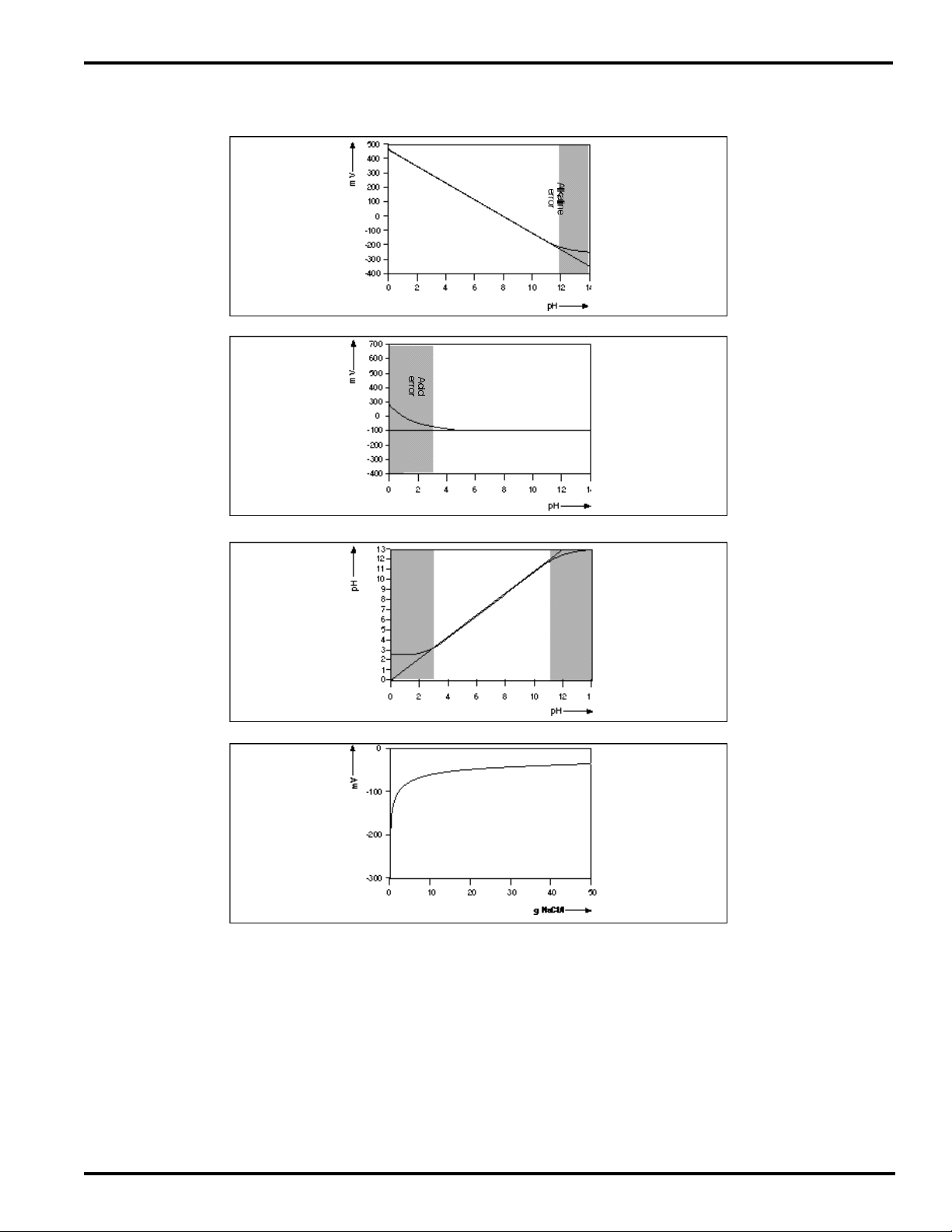
The response curves Fig. 1 (pH), Fig. 2 (reference) and
Fig. 3 (application range) show the way in which the
potential is generated at each element and combined
in the output of the sensor.
Fig. 1 Above pH11 the effect of sodium on the pH
membrane starts to cause non-linearity (Sodium
error)
Fig. 2 Below pH3 the high Hydrogen ion content
causes a change in the reference response
Fig. 3 A linear response to pH is obtained between 3
and 11 pH
Fig. 4 A plot of reference voltage against Sodium
content.
The revolutionary measuring principle has some big
advantages. The absence of lling solutions and
reference junctions virtually eliminates the problems
caused by aging and pollution of the reference sensor.
Regular cleaning of the sensor virtually eliminates drift,
and the sensor benets from a very long working life. It
is vital, however, to t the sensor to the application
correctly. The special nature of the reference element
dictates that there must be a certain Sodium level in
the process.
Fig. 4 shows a plot of reference voltage against
Sodium content.
Because of the exponential nature of the response, it
is plain that above about 0.5 N Na+ (30 g NaCl/l) in the
solution, the reference output remains virtually constant.
Of course when the Sodium concentration remains
constant in a process the reference voltage will also be
constant at much lower levels of Sodium.
It is because of the need to evaluate the chemistry
of the process, that it is necessary to have an
Application Data Sheet (page 16) completed before
approval for this sensor can be made.
The mechanical construction of the sensor also means
that it may be used in processes involving both high
temperatures and pressures. By eliminating the lling
solutions, the sensor is truly robust and can even
withstand severe thermal shocks that would ruin most
systems.
The stainless steel mounting adapter forms the liquid
earth (solution ground) connection needed to ensure
best stability of measurement. EXA also uses this
connection in the diagnostic circuit.
The PH18 is a differential pH sensor. It does not
measure absolute pH except in limited applications.
It does, however, measure a single control
point accurately, repeatably and with minimum
maintenance.
IM 12B6J4-E-A
Page 7
7
4
Measuring Enamel mV vs.
pH in solution containing
+
0.1N Na
Operating range
pH of sample
Fig. 1
Reference Enamel mV vs
pH in solution containing
+
0.1N Na
Operating range
pH of sample
Fig. 2
Fig. 3
Fig. 4
PH18 system output
pH reading vs. pH in
solution containing
+
0.1N Na
Operating range
pH of sample
Reference Enamel mV vs Na+content
IM 12B6J4-E-A
Page 8

8
2. GENERAL SPECIFICATIONS
2-1. Model PH18 differential pH sensor
Temperature sensor
: Pt1000 W RTD
Wetted parts
- pH sensor : pH sensitive enamel
- Reference sensor : Na+ sensitive enamel
- Liquid earth : via SS adapter
- O-rings : EPDM
- Adapters : SS 316
Max. measuring range
: 3 to 11 pH
(The actual range will be advised with reference to the completed application data sheet)
Temperature range : 0 to 140 ºC (284 ºF)
Pressure range : -1 to 15 Bar (214 psi)
NOTE:
The use of this sensor is highly application specic. Your local Yokogawa sales ofce will be
pleased to advise on the suitability of your application, on receipt of the completed
application data sheet. Any and all information received by Yokogawa will be treated in the
strictest condence. To maintain traceability, the completed application data sheet will form
part of the contract of sale.
Yokogawa offers no function guarantee for applications where the attached data sheet
(page 16) has not been satisfactorily completed. This does not affect the normal Yokogawa
warranty covering defects in materials or workmanship.
MODEL AND SUFFIX CODE
Model Sufx
code
PH18 ............ ................ Model PH18 Differential pH sensor
Sensor
mounting
O-ring
material
Instruction
manual
Options SA K1520EK Angled weld-in adapter (SS316)
-SA...... ................ Compatible with 25mm process connection
-E... ................ Ethylene-propylene (EPDM)
-E... ................ English language
Option
Description
code
K1520EJ STRAIGHT WELD-IN ADAPTER (SS316)
M1289BA ADAPTER 1” NPT (SS316)
237230 BLIND PLUG SS316
Note:
The sensor is supplied with
cable connector. For rst
installation cable must be
specied as well. (see par.2-2)
Note:
The material certicate 3.1.B is
supplied with the sensor and
the options.
IM 12B6J4-E-A
Page 9
2-2. Model WU18 cable for model PH18
differential pH sensor
Max. temperature :110 ºC (230 ºF)
Material :Thermoplastic Rubber (T.P.R.)
Colour :Blue.
Shipping details sensor and adapter
- Package :wxhxd 350 x 220 x 110 mm
- Weight :approx. 1.4 kg
Shipping details cable
- Package :wxhxd 350 x 220 x 110 mm
- Weight :2 m. approx. 0.6 kg
:5 m. approx. 0.9 kg
:10 m. approx. 1.4 kg
MODEL AND SUFFIX CODE
9
Model Sufx
code
WU18 ............ ................ Cable for Differential pH Sensor
-02......
-05......
-10......
Option
Description
code
................ 02 meter connection cable
................ 05 meter connection cable
................ 10 meter connection cable
IM 12B6J4-E-A
Page 10

10
4
DIMENSIONS PH18-SA
Fig. 7. PH18-SA and the adapters
Fig. 8. External dimensions of the PH18-SA
237574
237202
237230
PH18SA
in mm (inches)
M1289BA
K1520EJ
K1520EK
7
2-3. Dimensions of the PH18-SA
in mm (inches)
Fig. 5 PH18-SA and the adapters Fig. 6 External dimensions of the
44
(1.73)
K1520EJ
242574
51
(2.09)
PH18-SA
55
(2.17)
26
(1.02)
1”
237202
K1520EK
M1289BA
M1289BA 237230
237230
22.5
(0.89)
IM 12B6J4-E-A
Page 11

11
3. THE TYPE 18 PH PROBE
3-1. Typical applications
• Fermentation
• Continuous reactions
• Production of diary products
• Product monitoring
3-2. Handling information for the glass
lined pH probe.
The differential pH probes are pressure and thermal
shock resistant due to the fused steel/enamel
construction. The probes have a very high mechanical
stability and are extremely strong.
Inappropriate handling, e.g. hitting and scratching the
probe on steel, ceramics, glass or stone may cause
damage to the probe. Depending on the scope of the
damage, the probe may not fail immediately but
rather when the temperature changes. If a defective
measuring probe remains in aqueous solutions for
prolonged periods of time enamel may ake.
2. Fasten probe with union nut
3. Connect cable. For this purpose, loosen the heavy
gauge conduit connection at the protective plastic
cover, push out the connector, put the connector in
the proper position, and rmly press it into the
female connector of the probe (water- tight
interlock). Push the protective cover and O ring
sealing onto the probe until the stop and tighten the
heavy gauge conduit connection again manually.
4. The cable with high temperature stability (blue) must
be fastened vibration free. The cable must not be
laid together with power cables.
Only suitable transmitters with symmetrical
high impedance inputs may be used. The
following units are approved:
• Yokogawa EXA PH 202
• Yokogawa EXA PH 402w
Enable the EXA impedance monitoring. If sensor
damage is indicated, the measuring probe must be
immediately removed (within 24h) after an alarm
message. All probes for use in the food sector are
tested with a voltage of 12 kV and conditioned for 5
hours in steam at a temperature of 134 °C.
3-3. Storage and hydration
The PH18 Probe can be stored dry for an indenite
period of time at temperatures between -30 and +80
ºC. After prolonged storage or if this is a new probe
from the factory a simple steam sterilization should
be performed for 15-30 minutes prior to calibration.
This procedure revitalizes the probes giving it a stable
reference potential. If steaming is not possible soak
the PH 18 for 45-60 minutes in hot water (65 to 85 ºC).
If steaming or a hot soak can not be done, place the
Probe in a standard pH7 Buffer solution for 24 hours
prior to installation. The probe must be immersed
so that both measuring elements are covered with
buffer.
3-4. Installation
Procedure:
1. Remove the probe from the packaging, remove the
protective plastic hose and carefully introduce the
probe into the nozzle.
IM 12B6J4-E-A
Page 12

12
9
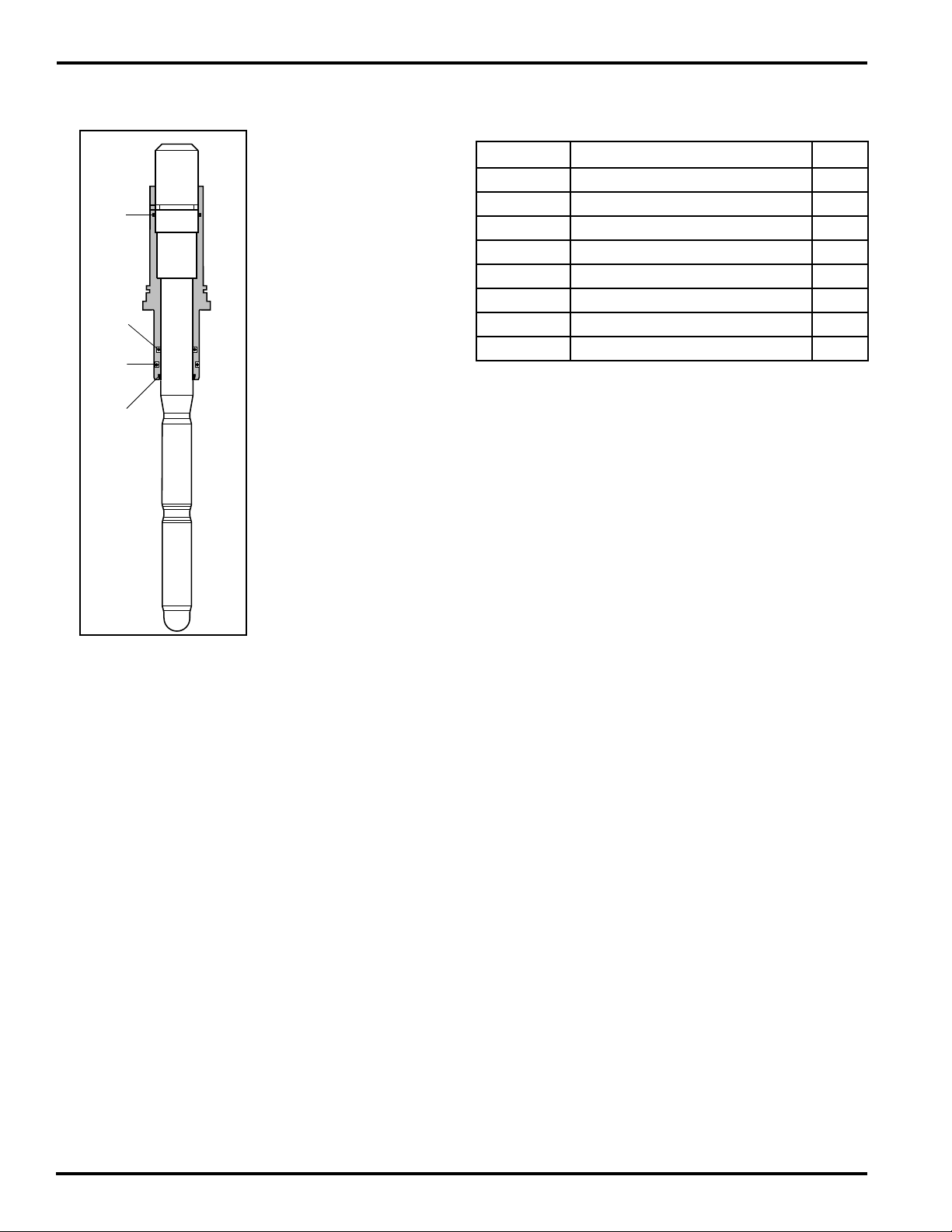
3-5. PH18 Installation examples
3-5. PH18 Installation examples
Socket for connection
cable
Primary adapter
pH enamel
Fig. 11 The primary adapter is used to make a
connection to the process used by the transmitter as
the liquid earth (solution ground). This is needed for
optimum stability of the measurement and is used in
the impedance checking circuit.
Example A. Straight weld-in adapter through a vessel
wall.
Example B. 1” Screw-in adapter with existing pipe
nipple through a vessel wall.
Example C. Angled weld-in adapter in large bore pipe.
Example D. Angled weld-in adapter mounted in a
bend
Example E. Screw or weld-in adapter mounted in a
large bore pipe.
Example F. Screw or weld-in adapter mounted on top
Reference enamel
Fig. 12. Model 18 elements
Note 1:
When measuring in plastic tanks or pipes, ensure that the adapter is
wetted by the process. Avoid installations where an air pocket can
be created (see g 12 F). This isolates the adapter, and hence loses
the liquid earth connection.
Note 2:
Flow rate from the side of the sensor (Fig 11) should not exceed 2
meters/second in low viscosity uids. In high viscosity uids (> 5cP)
use only installation as
shown in Fig. 12 (D).
IM 12B6J4-E-A
Page 13

13
ENGLISH
11
4-1. Set-up
The EXA PH202 and PH402 are both
designed with dual matched high
impedance inputs which are necessary
when using a pH probe like the Model PH
18 with both a measuring and a reference
electrode that are high impedance. To
prepare the EXA instrument to work with
the PH18 make sure the input impedance
jumpers are placed in the correct positions:
PH202: See table 3-1 and fig. 3-8 on
page 3-7 in the PH202 Instruction
Manual (IM 12B6C3-E-H) for
jumper positions.
PH402: See figure 3-9a on page 3-8 in the
PH402 Instruction Manual
(IM 12B6B3-E-H) for jumper
positions.
Since the Model PH18 has high impedan-
ces for both the measuring and the
reference elements, the high impedance
check functions (Service Codes 03 & 04)
must be set up according to the procedures
outlined in Section 5.3.1 in either the PH202
or the PH402 Manual.
The Calibration check also needs to be
changed. Here you are instructed to set:
Service Code 03:
Change settings from 1.1.1 to 1.0.1 by
using the ^ and > keys.
Low limit 1Megohm. High limit 1 Gigaohm.
Service Code 04:
Change settings from 0.0.1 to 1.0.1 by
using the ^ and > keys.
Low limit 1Megohm. High limit 1 Gigaohm.
Service Code 05:
Change settings from 1.1 to 0.1 by using
the ^ and > keys. This disables the As.
Pot. check which is not appropriate for the
PH18 system.
Once the jumpers and impedance Service
Codes (03 & 04), Calibration Check (05)
and Temperature element have been set
correctly, wire the probe cable to the
instrument as shown in Fig. 13. Power
wiring instructions are located in the
respective instrument manuals:
PH202: See section 3-4-3 on page 3-6 in
the PH202 Instruction Manual
(IM 12B6C3-E-H).
PH402: See section 3-3-3 on page 3-5 in
the PH402 Instruction Manual
(IM 12B6B3-E-H).
4. EXA PH202 OR PH402 INSTRUMENT
0 1 2 4 6 8 10 12 14
60
140
120
100
80
60
40
20
0
NOT RESISTANT
RESISTANT
1
pH of sample
Measuring range
ENGLISH
11
Service Code 03:
Change settings from 1.1.1 to 1.0.1 by
using the ^ and > keys.
Low limit 1Megohm. High limit 1 Gigaohm.
Service Code 04:
Change settings from 0.0.1 to 1.0.1 by
using the ^ and > keys.
Low limit 1Megohm. High limit 1 Gigaohm.
Service Code 05:
Change settings from 1.1 to 0.1 by using
the ^ and > keys. This disables the As.
Pot. check which is not appropriate for the
PH18 system.
Once the jumpers and impedance Service
Codes (03 & 04), Calibration Check (05)
and Temperature element have been set
correctly, wire the probe cable to the
instrument as shown in Fig. 13. Power
wiring instructions are located in the
respective instrument manuals:
PH202: See section 3-4-3 on page 3-6 in
the PH202 Instruction Manual
(IM 12B6C3-E-H).
PH402: See section 3-3-3 on page 3-5 in
the PH402 Instruction Manual
(IM 12B6B3-E-H).
4. EXA PH202/FLXA21 or PH402/
PH450 INSTRUMENT
4-1. Set-up PH202/PH402
The EXA PH202/FLXA21 and PH402/PH450 are all
designed with dual matched high impedance inputs
which are necessary when using a pH probe like the
Model PH18 with both a measuring and a reference
electrode that are high impedance. To prepare the
Yokogawa instruments to work with the PH18 make
sure the input impedance jumpers are placed in the
correct positions:
PH202: See table 3-1 and g. 3-8 on page
3-7 in the PH202 Instruction Manual
(IM 12B6C3-E-H) for jumper positions.
FLXA21: See g. 3.11 on page 3-8 in the FLXA21
Instruction Manual (IM 12A01A02-01E) for
jumper positions.
PH402: See gure 3-9a on page 3-8 in the
Instruction Manual (IM 12B6B3-E-H) for
jumper positions.
PH450: See table 3-1 and gure 3-9a on page 12 in
the PH450 Instruction Manual
(IM 12B07C05-01E) for jumper positions.
4-2. Set-up PH202 and PH402
Since the Model PH18 has high impedances for both
the measuring and the reference elements, the high
impedance check functions (Service Codes 03 & 04)
must be set up according to the procedures outlined
in Section 5.3.1 in either the PH202 or the PH402
Manual. The Calibration check also needs to be
changed. Here you are instructed to set: The
Calibration check also needs to be changed. Here you
are instructed to set:
Service Code 03:
Change settings from 1.1.1 to 1.0.1 by using the ^ and
> keys. Low limit 1 Megohm. High limit 1 Gigaohm.
1
15
8
9
2
5
&34 6
Model PH18
sensor
FIG.13 Connection diagram WU18 for
PH202/FLXA21 and PH402/PH450
measure
16
screen
17
screen
13
reference
14
liquid
12
temperature
11
temperature 2
Service Code 04:
Change settings from 0.0.1 to 1.0.1 by using the ^ and
> keys. Low limit 1 Megohm. High limit 1 Gigaohm.
Service Code 05:
Change settings from 1.1 to 0.1 by using the ^ and
> keys. This disables the As. Pot. check which is not
appropriate for the PH18 system.
Once the jumpers and impedance Service Codes (03
& 04), Calibration Check (05) and Temperature element
have been set correctly, wire the probe cable to the
instrument as shown in Fig. 13.
For the FLXA21/PH450
Since the Model PH18 has high impedances for
both the measuring and the reference elements, the
impedance setting must be set up to reect dual high
impedance according to the procedures outlined in
Section 5-6 in the PH450 or in Section 5.2.5in the
FLXA21 Manual. The Calibration check also needs to
be changed. Here you are instructions to set:
Impedance Settings:
Select the Execute Wrench from the Main Display.
Select Commissioning Measurement Setup
Impedance Settings
Ensure that Input 1 and Input 2 are set to High
Press the Home key to return to measuring mode.
Once the jumpers and impedance Settings have
been changed correctly, wire the probe cable to the
instrument as shown in Fig. 13.
Power wiring instructions are located in the respective
instrument manuals:
PH202: See section 3-4-3 on page 3-6 in the PH202
Instruction Manual (IM 12B6C3-E-H).
FLXA21: See section 3.3 on page 3-4 in the FLXA21
Instruction Manual (IM 12A01A02-01E).
PH402: See section 3-3-3 on page 3-5 in the PH402
Instruction Manual (IM 12B6B3-E-H).
PH450: See section 3-3-3 on page 10 in the PH450
Instruction Manual (IM 12B07C05-01E).
60
1
140
120
100
80
earth
1
60
40
20
0
0 1 2 4 6 8 10 12 14
pH of sample
FIG.14 Corrosion curve of the Model
PH18 Enamel
Measuring range
NOT RESISTANT
RESISTANT
IM 12B6J4-E-A
Page 14

14
12
5. CALIBRATION
5-1. Calibration set-up
All pH sensors are characterized by
Isopotential (ITP), Asymmetry Potential
(ASY) and SLOPE (SL). Typically the ITP is
set by the factory for specific sensor types
and the ASY and the SL are adjusted by the
user during his buffer calibrations.
Calibration of the PH18 is slightly different
from calibration of conventional pH
sensors due to the differential nature of
the measurement. The ITP and SL are set
during commissioning and ASY is adjusted
by the user during his Grab Sample
calibrations.
5-2. Isopotential pH value
to perform a regular SLOPE check to verify
proper functioning of the sensor.
5-4. ASYMMETRY Potential
The default setting for Asymmetry potential
is 0 mV at Isopotential pH value. This value
is always wrong for the PH18 sensor and
therefore the Asymmetry Potential must
be calibrated always. This cannot be done
with conventional pH buffer solutions,
since these buffer solutions will have salt
compositions, which differ from the actual
process. Therefore the calibration is done
using the grab sampling method: During
the most important stage of the pH control
application a sample is drawn and the pH
of the sample is measured with a calibrated
conventional pH meter. The analyzer is
adjusted to this value using the MAN.CAL
mode.
Notes: This adjustment should be done
at the normal working temperature at the
most important stage of the process (the
control setpoint, or the critical part of the
pH profile). This avoids the need for process
temperature compensation for constant
temperature processes.
ITP as function of Conductivity for Na Cl
5. CALIBRATION
5-1. Calibration set-up
All pH sensors are characterized by Isopotential (ITP),
Asymmetry Potential (ASY) and SLOPE (SL). Typically
the ITP is set by the factory for specic sensor types
and the ASY and the SL are adjusted by the
user during his buffer calibrations. Calibration of
the PH18 is slightly different from calibration of
conventional pH sensors due to the differential nature
of the measurement. The ITP and SL are set during
commissioning and ASY is adjusted by the user during
his Grab Sample calibrations.
5-2. Isopotential pH value
8
6
4
pH
2
0
0,01 0,1 1 10 100
mS/cm
Fig. 15 ITP Curve
The default setting for the Isopotential point is 0 mV
at 7.00 pH, because most manufacturers of Glass
electrodes use 7 pH as internal ll solution. The PH18
differential sensor has two measuring elements: one
pH element which has an Isopotential pH value of 1 pH
and one pNa element, which has an Isopotential pNa
value of –2. The Isopotential pH value of the differential
sensor depends on the Salt concentration. It is
recommended to set the ITP as a function of the
Conductivity according to the graph.
5-3. SLOPE
The default setting for SLOPE is 100% of theoretical
value, which is 59,16 mV/pH@25°C. It is only possible
to calibrate the SLOPE, if pH buffers are used with
identical salt concentration. These buffers are not
commercially available, so it is recommended not to
perform a SLOPE calibration, but leave the analyzer
in its default settings. It is however recommended
to perform a regular SLOPE check to verify proper
functioning of the sensor.
5-4. ASYMMETRY Potential
The default setting for Asymmetry potential is 0 mV
at Isopotential pH value. This value is always wrong
for the PH18 sensor and therefore the Asymmetry
Potential must be calibrated always. This cannot be
done with conventional pH buffer solutions, since
these buffer solutions will have salt compositions,
which differ from the actual process. Therefore the
calibration is done using the grab sampling method:
During the most important stage of the pH control
application a sample is drawn and the pH of the
sample is measured with a calibrated conventional pH
meter. The analyzer is adjusted to this value using the
MAN.CAL mode.
Notes: This adjustment should be done at the normal
working temperature at the most important stage of
the process (the control setpoint, or the critical part of
the pH prole). This avoids the need for process
temperature compensation for constant temperature
processes.
5-5. Process Temperature
Compensation
This setting is needed only when the temperature of
the process is not (reasonably) constant. When setting
process TC, it should be done before step 5-4. to
avoid inuencing the Asymmetry potential calibration.
The procedure is as follows: -Allow sensor to stabilize
fully in the process. Note down the temperature and
pH readings (t1 & pH1). Allow sample and sensor to
cool (together) to room temperature, and stabilize.
Again note down the temperature and pH readings (t2
& pH2) T.C. = (pH1-pH2)x10/(t1-t2) pH/10°C
NOTE: to calculate TC from temperature readings in
Fahrenheit, TC = (pH1-pH2)x18/(t1-t2) of a large bore
pipe
IM 12B6J4-E-A
Page 15

6. CLEANING/STERILIZATION 7. MAINTENANCE
15
The probe can be cleaned/sterilized inside the
reactor. For CIP cleaning it must be ensured that the
admissible alkali and acid concentration as well as the
maximum temperature or cleaning time are not
exceeded. Otherwise, the enamel of the electrode
would be subject to increased corrosion.
NOTE: With alkali cleaning, corrosion is doubled with
every temperature jump of 10 ºC. The use of
oxidizing acids, such as HNO3, is limited to
solutions of 1.5% at a maximum of 50 °C.
6-1. Acceptable CIP cleaning processes
1. 1.5 - 2% alkaline solution, max 85 ºC, max 1 hour.
2. 1.5% acid (HNO3), 50 ºC, max. 15 min.
3. Steam 134 ºC, max. 2 hours
After cleaning with alkaline solution without acid and
steam sterilization, a transitional measuring error may
occur if the wetting time is too short.
6-2. Sterilization methods
The probe is resistant to the following sterilization
methods:
• with product
• with steam
• with alcoholic solutions
• with antiseptic solutions
The PH18 does not normally require maintenance, as
long as it is kept clean. Buffer checks may be done if it
is suspected that the sensor performance has
drifted appreciably. It is best, however, simply to do
a single point “Manual” calibration against a grab
sample taken at the process temperature and normal
pH value.
For cleaning or removal of residues dilute acids may
be used for a short time at room temperature only.
Limescale may be removed with commercially
available “antiliming” agents. The non-abrasive
material intended for ceramic cookers may be used to
remove sticky coatings from the PH18 - Do not use
any metallic or abrasive substances!
IM 12B6J4-E-A
Page 16
16
9. ACCESSORIESl
PH18 differential pH sensor
A
C
D
A
B
C
E
Number Description Q’ty
K1500BJ Set O-rings 20.3 x 5
2.62 (EPDM) unit
K1500BK O-ring 20.3 x 2.62 1
(KALREZ) unit
K1500BQ Set O-rings 17.12 x 1
2.62 (KALREZ) unit
K1500BR Set O-rings 17.12 x 2.62 5
(EPDM) unit
K1500BS Set O-rings 25.12 x 1.78 1
(EPDM) unit
K1522FK Set O-rings 17.04 x 3.53 5
(EPDM) unit
K1522FL Set O-rings17.04 x 3.53 1
(KALREZ) unit
K1500BT Nut 1
K1522ER /SWR Straight 1
weld-in adapter
K1522EQ /SWA Angled 1
weld-in adapter
K1522ET /SBS Adapter 1
ISO 7/1-R1, JIS 1”
K1522ES /SNS Adapter 1
1” NPT
PH18-SE
8. POSITION OF THE O-RINGS
PH18-SA
9. ACCESSORIES
PH18 differential pH sensor
Number Description Q’ty
M1263YB O-ring 20.0 x 2.5 (EPDM) unit 1
M1263YC O-ring 17.0 x 2.5 (EPDM) unit 1
M1263XZ O-ring 25.0 x 1.5 (Viton A) unit 1
K1500BT Nut 1
K1520EJ Straight weld-in adapter 1
K1520EK Angled weld-in adapter 1
M1289BA Adapter 1” NPT 1
237230 Blind plug 1
Size of the O-ring Materials
A= 17.0 x 2.5 EPDM-FDA Approved
B= 20.0 x 2.5 EPDM-FDA Approved
C= 25.0 x 1.5 Viton A
D= 17.0 x 3.0 EPDM
Fig. 16 Location of the O-rings
IM 12B6J4-E-A
Page 17
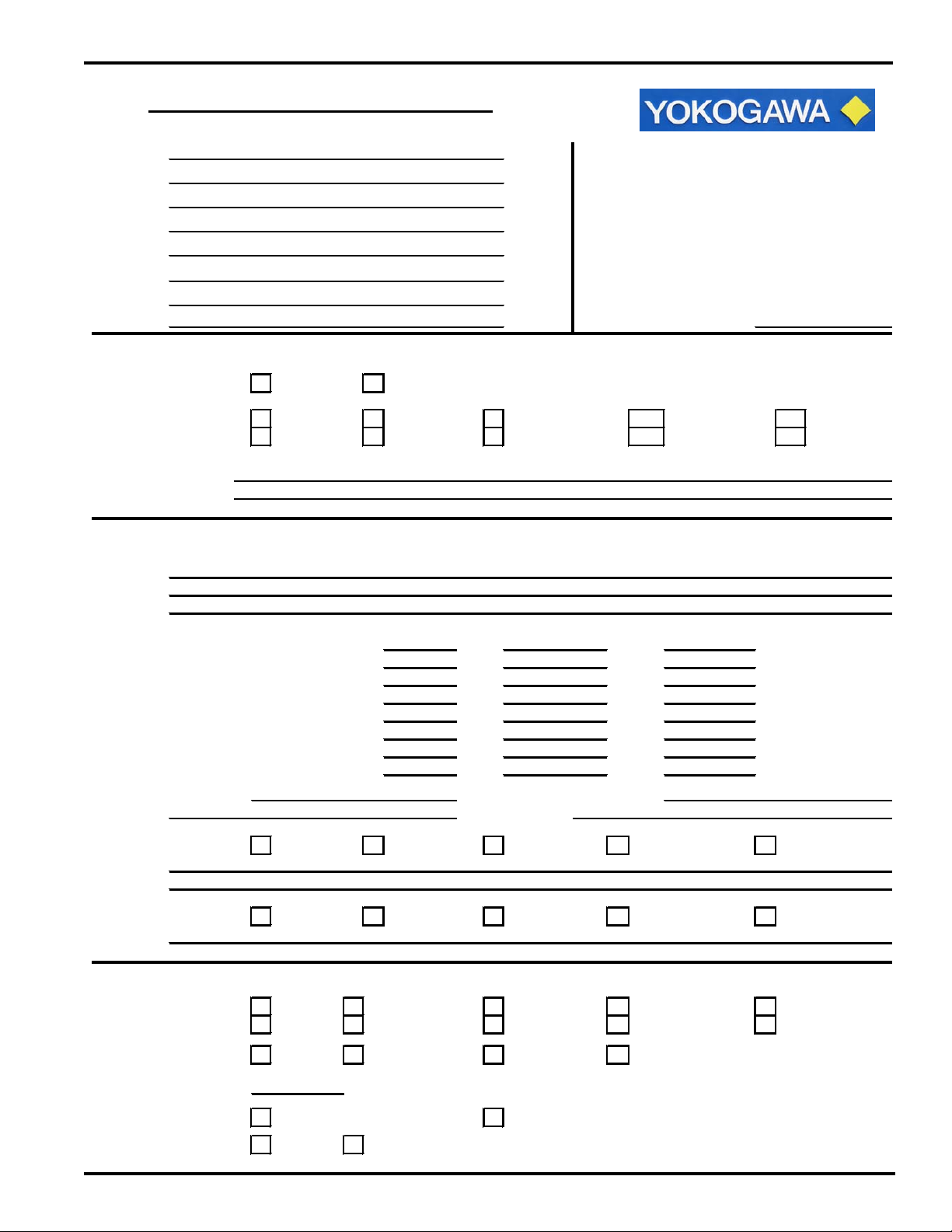
SC24V or PH18 Application Data Sheet
Address:
Contact:
Rep Name: Authorization No.
1. PROCESS DATA:
2. PROCESS CONDITIONS:
3. INSTALLATION DATA:
Customer: Please complete a seperate form for each process
Tag No: stream to be analyzed and return to the attention of:
Yokogawa Corporation of America
Analytical Business Unit
2 Dart Road
Telephone: Newnan, Georgia 30265 - 1040
Email: FAX - (770) 304-1613
17
Sensor Selection:
Application: Chemical Power Pharmaceutical Pulp & Paper Other
Operation Batch Control Continous Monitor Other
Type of Solution:
Descrition:
pH Value Max
Conductivity Value Max
Sodium Concentration Max
Temperature (°C/°F) Max
Pressure (psig) Max
Flow Rate (ft/sec) Max
Concentration of Solids: Concentration of Organics:
Type(s): Type(s):
PH18 SC24V
Min
Min Norm
Min
Min
Min
Min Norm
NormMin
Norm
Norm
Norm
Norm
NormMin
Max
Max
Problems: Fouling Abrasion Coating Poisoning Other
Describe:
Cleaning/Sterilization: w/ Product Caustic Steam Hot Water Other
Describe:
Mounting: Insertion Flow Through Retractable Immersion Other
Off Line On Line Pipe On Line tank Sample Line Flanged
Wetted Materials: 316SS EPDM Kynar Kalrez
Distance to Converter:
Instrument: General Purpose Intrinsic Safe
Power Supply: 115 VAC 24 VDC
ft
IM 12B6J4-E-A
Page 18

Yokogawa Corporation of America
North America
2 Dart Road, Newnan, GA 30265-1094, USA
Phone: 800-258-2552 Fax: 770-254-0928
12530 West Airport Blvd., Sugar Land, TX 77478
Phone: 281-340-3800 Fax: 281-340-3838
Mexico
Melchor Ocampo 193, Torre C, Ocina 3”B”
Veronica Anzures D.F., C.P. 11300
Phone: (55) 5260-0019, (55) 5260-0042
Yokogawa Canada, Inc.
Bay 4, 11133 40th Street SE, Calgary, AB Canada T2C2Z4
Phone: 403-258-2681 Fax: 403-258-0182
Yokogawa has an extensive sales and
distribution network.
Please refer to the website
(www.yokogawa.com/us) to contact your
nearest representative.
IM 12B6J4-E-A 02-1207 (A) I
Subject to change without notice Printed in The USA
Copyright ®
 Loading...