

Page 1

User’s
Manual
Model PH100
Panel Mount pH Converter
IM 12B11A01-01E
IM 12B11A01-01E
1st Edition
Page 2

r Introduction
This manual covers the specifications, installation, operation and maintenance of the
panel-mount version of the PH100 pH converter. Please read this before using the PH100.
There are manuals for the related EXA100 series as follows:
Refer to them as required.
Model code Manual Name IM No.
PH100 Panel Mount pH Converter IM 12 B11A01-01E
OR100 Panel Mount ORP Converter IM 12 C11A01-01E
SC100 Panel Mount Conductivity Converter IM 12 D11A01-01E
PH10FP KCl Refillable pH Sensor IM 12 B11C01-01E
PH10RP KCl Replenish-free pH Sensor IM 12 B11C02-01E
OR10FP KCl Refillable ORP Sensor IM 12 C11C01-01E
OR10RP KCl Replenish-free ORP Sensor IM 12 C11C02-01E
SC10XB Conductivity Sensor for SC100 IM 12 D11C01-01E
WTB100 Terminal Box for EXA100 IM 12 B11E01-01E
WF100 Extension Cable for EXA100 IM 12 B11F01-01E
PH10HLD Immersion Holder for EXA100 IM 12 B11D01-01E
PH10HG Guide-pipe Holder for EXA100 IM 12 B11D02-01E
T000.eps
Safety Precautions
IM 12B11A01-01E
1st Edition: Apr. 2003 (YK)
All Rights Reserved, Copyright © 2003, Yokogawa Electric Corporation
IM 12B11A01-01E
i
Page 3
r For the safe use of this equipment
(1) About This Manual
• This manual should be passed on to the end user.
• The contents of this manual are subject to change without prior notice.
• The contents of this manual shall not be reproduced or copied, in part or in whole,
without permission.
• This manual explains the functions contained in this product, but does not warrant that
they will suit the particular purpose of the user.
• Every effort has been made to ensure accuracy in the preparation of this manual.
However, should any errors or omissions come to the attention of the user, please
contact the nearest Yokogawa Electric representative or sales office.
• This manual does not cover the special specifications. This manual may be left
unchanged on any change of specification, construction or parts when the change does
not affect the functions or performance of the product.
• If the product is used in a manner not specified in this manual, the safety of this
product may be impaired.
(2) Safety and Modification Precautions
• Follow the safety precautions in this manual when using the product to ensure protection and safety of personnel, product and system containing the product.
(3) The following safety symbols are used on the product as well as in this manual.
DANGER
This symbol indicates that the operator must follow the instructions laid out in this
manual in order to avoid the risk of personnel injury, electric shock, or fatalities. The
manual describes what special care the operator must exercise to avoid such risk.
WARNING
This symbol indicates that the operator must refer to the instructions in this manual in
order to prevent the instrument (hardware) or software from being damaged, or a system
failure from occurring.
CAUTION
This symbol draws attention to information essential for understanding the operation and
functions.
Tip
This symbol gives information that complements the current topic.
SEE ALSO
This symbol identifies a source to which to refer.
Protective Ground Terminal
Function Ground Terminal (Do not use this terminal as the protective ground
terminal.)
Alternating current
ii
IM 12B11A01-01E
Page 4
r NOTICE and Cautions
• Check specifications
When the instrument arrives, unpack the package with care and check that the
instrument has not been damaged during transportation. In addition, please check that
the specification matches the order, and required accessories are not missing. Specifications can be checked by the model codes on the nameplate. Refer to Chapter 1.2
Specifications for the list of model codes.
• Details on operation parameters
When the PH100 panel mount pH Converter at the user site, it will operate based on
the operation parameters (initial data Table 5.1 to 5.5) set before shipping from the
factory.
Ensure that the initial data is suitable for the operation conditions before conducting
analysis. Where necessary, set the instrument parameters for appropriate operation.
For details of setting data, refer to chapters 4 to 5.
When user changes the operation parameters, it is recommended to note down the
changed setting data.
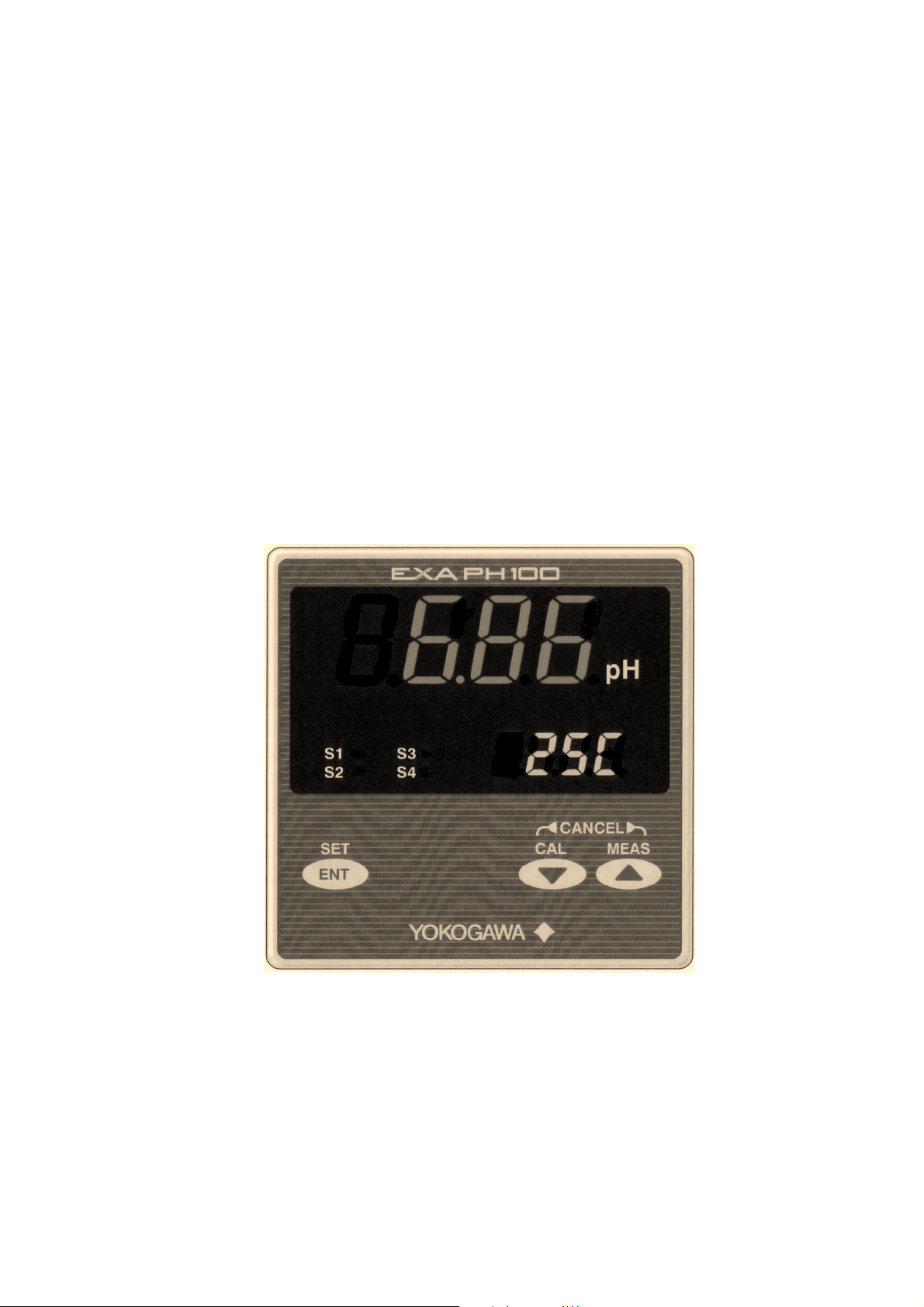
Safety Precautions
Front Panel of PH100
IM 12B11A01-01E
iii
Page 5

LED Display Symbols
• Alphanumerics are represented as follows on the LED display
Alphanumerics Alphanumerics AlphanumericsLED Display LED Display LED Display
A
B
C
D
E
F
G
H
I
J
K
L
N
O
P
Q
R
S
T
U
V
W
0
1
2
3
4
5
6
7
8
9
X
Y
M
Z
iv
IM 12B11A01-01E
Page 6

r After-sales Warranty
d During the warranty period, for repair under warranty carry or send the product to the
local sales representative or service office. Yokogawa will replace or repair any
damaged parts and return the product to you.
d Before returning a product for repair under warranty, provide us with the model
name and serial number and a description of the problem. Any diagrams or data
explaining the prpoblem would also be appreciated.
d If we replace the product with a new one, we won’t provide you with a repair report.
d Yokogawa warrants the product for the period stated in the pre-purchase quotation.
Yokogawa shall conduct defined warranty service based on its standard. When the
customer site is located outside of the service area, a fee for dispatching the maintenance engineer will be charged to the customer.
d In the following cases, customer will be charged repair fee regardless of warranty
period.
• Failure of components which are out of scope of warranty stated in instruction
manual.
Safety Precautions
• Failure caused by usage of software, hardware or auxiliary equipment, which
Yokogawa Electric did not supply.
• Failure due to improper or insufficient maintenance by user.
• Failure due to modification, misuse or outside-of-specifications operation which
Yokogawa does not authorize.
• Failure due to power supply (voltage, frequency) being outside specifications or
abnormal.
• Failure caused by any usage out of scope of recommended usage.
• Any damage from fire, earthquake, storms and floods, lightning, disturbances, riots,
warfare, radiation and other natural changes.
d Yokogawa does not warrant conformance with the specific application at the user
site. Yokogawa will not bear direct/indirect responsibility for damage due to a specific
application.
d Yokogawa Electric will not bear responsibility when the user configures the product
into systems or resells the product.
d Maintenance service and supplying repair parts will be covered for five years after
the production ends. For repair for this product, please contact the nearest sales office
described in this instruction manual.
IM 12B11A01-01E
v
Page 7

vi
IM 12B11A01-01E
Page 8

Contents
r Introduction ...................................................................................................................... i
r For the safe use of this equipment ................................................................................ ii
r NOTICE and Cautions ..................................................................................................iii
r After-sales Warranty ...................................................................................................... v
1. Overview .....................................................................................................................1-1
1.1 EXA PH100 pH converter .............................................................................. 1-1
1.2 Check the specifications ................................................................................. 1-1
1.3 Features of the EXA PH100 pH converter..................................................... 1-2
1.4 Standard Specifications ................................................................................... 1-2
2. Preparation for Operation ........................................................................................2-1
2.1 Unpacking ....................................................................................................... 2-1
2.2 Choosing an Installation Location .................................................................. 2-1
2.3 External Dimensions ....................................................................................... 2-2
2.4 Panel Cutout Dimensions................................................................................ 2-3
2.5 Mounting ......................................................................................................... 2-4
3. Wiring..........................................................................................................................3-1
3.1 Pulling in Wiring............................................................................................. 3-2
3.2 Noise prevention ............................................................................................. 3-3
3.3 Wiring Terminal Diagram............................................................................... 3-4
3.4 pH detector wiring .......................................................................................... 3-7
3.5 Wiring cable to intermediate terminal box..................................................... 3-9
3.6 Output Signal Cable Wiring ........................................................................... 3-9
3.7 Contact output wiring. .................................................................................... 3-9
3.7.1 Wiring when S1 is used .......................................................................... 3-9
3.7.2 Wiring for S2 (for two-contact-output case) or S2,
S3 and S4 (four-contact output case).................................................... 3-11
3.8 Power and Ground Wiring ............................................................................ 3-12
4. Overview of Operation Panel ................................................................................... 4-1
4.1 Overviews of names and functions of operation panel keys ......................... 4-1
4.2 Key Operation ................................................................................................. 4-2
4.3 Switching display screens ............................................................................... 4-3
4.4 Display screen examples ................................................................................. 4-4
4.4.1 Initial display ........................................................................................... 4-4
4.4.2 Measurement screen ................................................................................ 4-5
4.4.3 Calibration screen .................................................................................... 4-6
4.4.4 Setting screen........................................................................................... 4-7
IM 12B11A01-01E
vii
Page 9

5. Operation .................................................................................................................... 5-1
5.1 Start up ............................................................................................................ 5-1
5.1.1 Check wiring ........................................................................................... 5-1
5.1.2 Start up pH converter .............................................................................. 5-1
5.1.3 Data setting .............................................................................................. 5-1
5.1.4 Temperature Calibration........................................................................ 5-10
5.1.5 Calibration with Standard Liquid.......................................................... 5-10
5.2 Test Operation ............................................................................................... 5-11
5.3 Normal operation .......................................................................................... 5-11
5.4 Stopping and Restarting Operation............................................................... 5-11
6. Calibration with standard solution .......................................................................... 6-1
6.1 Important issues relating to calibration with standard solution ..................... 6-1
6.2 Calculations involved in Calibration with Standard Solution........................ 6-2
6.3 Preparation ....................................................................................................... 6-5
6.4 Auto calibration with standard solution .......................................................... 6-8
6.4.1 Setting parameters for auto calibration ................................................... 6-8
6.4.2 Procedure for auto calibration ................................................................. 6-8
6.5 Manual Calibration with Standard Solution ................................................. 6-12
6.5.1 Manual Calibration Parameter Settings ................................................ 6-12
6.5.2 Procedure for Manual Calibration......................................................... 6-12
6.6 Canceling Calibration .................................................................................... 6-14
6.7 Error during Calibration................................................................................ 6-14
6.7.1 Recovering from an Error ..................................................................... 6-14
6.7.2 Quitting calibration................................................................................ 6-14
7. Maintenance and Cleaning ....................................................................................... 7-1
7.1 Periodic Maintenance...................................................................................... 7-1
7.1.1 Electrode cleaning ................................................................................... 7-1
7.1.2 Calibration with Standard Liquid............................................................ 7-1
7.1.3 Checking the KCl in the Detector........................................................... 7-1
7.2 Preventative Maintenance ............................................................................... 7-2
7.2.1 PH Converter Terminal Isolation ............................................................ 7-2
7.2.2 Check the Display of the pH Converter ................................................. 7-2
8. Troubleshooting .......................................................................................................... 8-1
8.1 Unexpected value displayed
(narrowing down problem to converter or sensor) ........................................ 8-1
8.2 Error Display ................................................................................................... 8-4
8.3 Fixing Error Status .......................................................................................... 8-4
8.3.1 Error 1 pH Measurement Out of Range ................................................ 8-4
8.3.2 Error 2 Temperature Measurement Out of Range................................. 8-4
8.3.3 Error 3 Temperature Sensor Abnormal ................................................. 8-5
8.3.4 Converter Abnormal ................................................................................ 8-5
8.3.5 Calibration Error...................................................................................... 8-5
8.3.6 Asymmetry Potential Abnormal.............................................................. 8-6
8.3.7 Abnormal Slope of sensor emf characteristic ......................................... 8-6
8.3.8 Unstable Sensor Reading ......................................................................... 8-6
Revision Record .................................................................................................................... i
viii
IM 12B11A01-01E
Page 10
1. Overview
1.1 EXA PH100 pH converter
The EXA PH100 pH converter is a panel-mount unit with built-in general-purpose
preamp, large 4-digit LED display for measured value and 4-digit LED display for
settings.
1.2 Check the specifications
The model number and suffix codes are shown below. Check that what you were
supplied is the same as what you ordered.
1. Overview
Model
PH100
Label language
Contact output
Temperature
sensor
Option
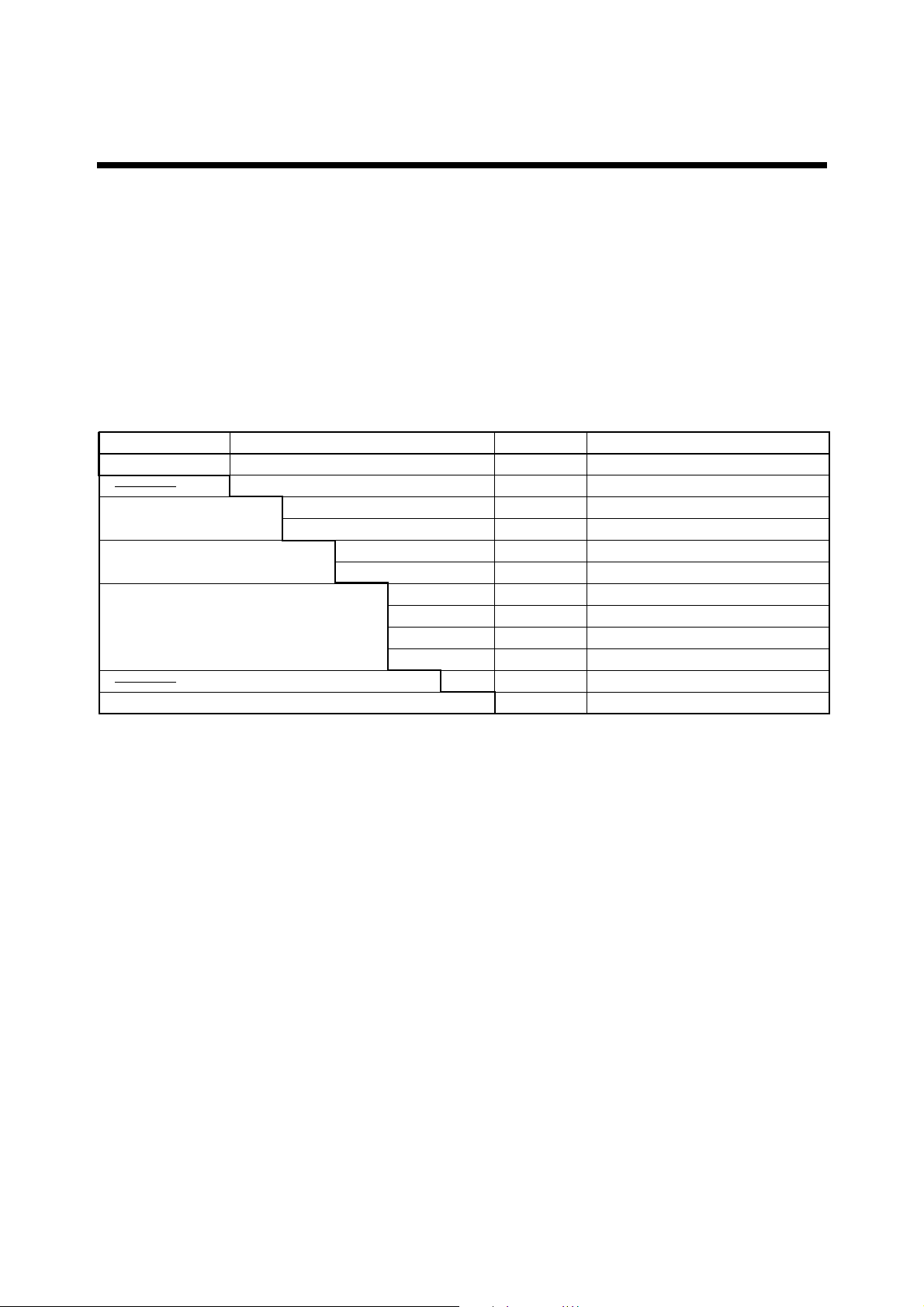
Suffix code Option code Description
Panel mounted pH converter
-A
-E
-J
-21
-41
-T1
-T2
-T3
-T4
-NN
Construction
Always -A
English
Japanese
2 contact outputs
4 contact outputs
Pt1000/Pt100
Pt1000/500 Ω
Pt1000/10 kΩ
Pt1000/6.8 kΩ
Always -NN
IP65/65
T1.2E.EPS
IM 12B11A01-01E
1-1
Page 11

1.3 Features of the EXA PH100 pH converter
(1) Large 4-digit display. Both measured pH value and temperature can be displayed at
the same time.
(2) You can easily calibrate the unit with pH4, pH7 or pH9 standard solution.
(3) You can select either two output contacts or four ; and you can select each contact
output type from : high, low, high high, low low, and high high / low low.
(4) Isolated 4 to 20 mA analog output of measured value.
(5) Calibration values and measured values can be read to 0.01 pH, making high accuracy
measurement and calibration possible.
(6) The operation panel is rated for operation in an IP55. IP65 is optional.
(7) 96 mm x 96 mm DIN size panel mount instrument. Depth is 120 mm and weight is
600 g.
(8) Full set of self-diagnostic functions with indication of errors such as measurement
out of range, converter abnormal, calibration-time error.
1.4 Standard Specifications
Measurement : Hydrogen ion concentration (pH) of a solution
Measuring range : -2.00 to 14.00 pH Indication
Display
Display : Digital (LED)
Range : -2.00 to 16.00 pH
Resolution : 0.01 pH (pH reading), 1 8C (temperature reading)
Indication items : pH reading, setting, status, temperature *
*1: Indication “enabled/disabled” selectable
Input signal
pH input range : -2 to 16 pH
pH input impedance : 1012 V or more
Temperature input *2 : Pt1000/Pt100, Pt1000/500 V, Pt1000/10 kV, Pt1000/6.8 kV
*2 : Must be specified when ordering.
Temperature input range : -10 to 110 8C
Transmission signal output
Number of output points : 1 output, pH reading only
Output signal : 4 to 20 mA DC, isolated
Load resistance : 600V or less
Transmission signal range : Configurable within pH-2.0 to pH 16.0 (Detault : pH0.0 to
pH 14.0)
Minimum span : 2 pH
Maintenance output signal : Output hold “enabled/disabled” selectable
Hold output value : Last measured value/preset value (2.0 to 20.8 mA) selectable
Fail output signal : Downscale burnout (2 mA) “enabled/disabled” selectable
1
1-2
IM 12B11A01-01E
Page 12
Contact output
Contact type : Relay contact output
Number of contacts : 2 or 4 outputs (must be specified when ordering)
Contact action : On/Off action
Contact functions : Selectable; High, low, high-high, low-low, high-high/low-low limit
alarms, FAIL
Contact output hysteresis : 0.0 to 4.0 pH (configurable)
Contact output delay time : 0 to 200 seconds (configurable)
Contact rating : When 2 contact outputs specified
S1 : 240 VAC 3A or 30 V DC 3A (resistance load), Form C (NC/NO/COM, 3
terminals)
S2 : 240 VAC 3A or 30 V DC 3A (resistance load), Form A
When 4 contact outputs specified
S1 : 240 VAC 3A or 30 V DC 3A (resistance load), Form C (NC/NO/COM, 3
terminals)
S2, S3, S4 : 240 V AC 3A or 30 V DC 3A (resistanceload), Form A, shared common
Maximum load current on common is 3A.
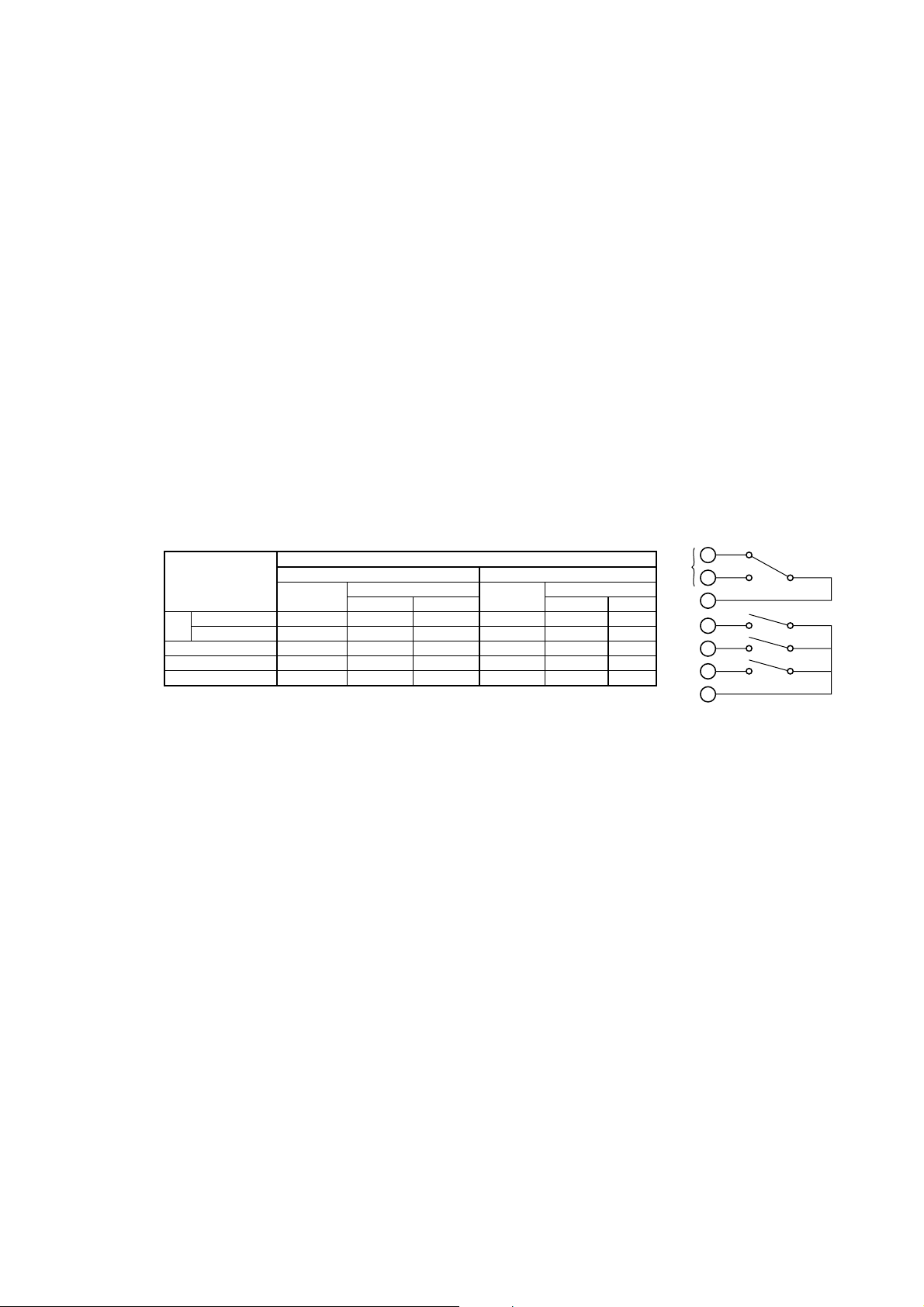
Contact status:
Table 1.1
Contact
S1 NO-COM Open Open Closed Open Closed Open
NC-COM Closed Closed Open Closed Open Closed
S2 Open Open Closed Open Closed Open
S3 when specified Open Open Closed Open Closed Open
S4 when specified Open Open Closed Open Closed Open
Note: When a contact is activated, the LED on display panel turns on.
Function selected
H, L, HH, LL, HH/LL limit alarms FAIL
Power off
Power on
No alarm Alarm No alarm Alarm
Power off
Power on
Terminal
1
S1
2
COM
3
4
S2
5
S3
6
S4
COM
7
1. Overview
NC
NO
Ambient temperature : -5 to 45 8C
Storage temperature : -25 to 70 8C
Ambient humidity : 10 to 90% RH, non-condensing
Installation altitude : 2000 m or less above sea level
Construction : Front panel : Dust-proof and drip-proof construction IP55,
IP65 (when “/65” option specified)
Materials : ABS resin and polycarbonate
Power supply : Rated voltage 100 to 240 V AC (610%), 50/60 Hz
Power consumption : Max. 9 VA
Weight : Approx. 600g
Dimensions : 96 (W) 3 96 (H) 3 120 (D) mm
Mounting : Panel mount
Panel cutout dimensions : 92 (W) 3 92 (H) mm
Wiring : M3.5 screw terminal
Grounding : grounding resistance 100 V or less
Functional specifications
Asymmetry potential adjustment range : 762 pH
Slope adjustment range : 70 to 110% of theoretical value
Automatic temperature compensation range : -10 to 110 8C, manual temperature
compensation available (setting range : -10 to 110 8C)
Temperature correction function (cable length correction by one-point temperature
calibration)
IM 12B11A01-01E
1-3
Page 13

Calibration function
One touch automatic calibration (one or two point calibration)
Standard solution table : Selectable : JIS • NIST Table (4, 7, 9 pH)
DIN 19267 Table (4, 7, 9 pH)
US Technical Buffer Table (4, 7, 10 pH)
Standard solution temperature range : 0 to 95 8C for JIS • NIST Table
0 to 90 8C for DIN 19267 Table
0 to 60 8C for US Technical Buffer Table
Manual calibration (one or two point calibration at specified setpoint(s))
Self-diagnostics function
FAIL output : pH measurement range failure, temperature measurement range failure,
temperature detection element failure, and converter failure
Detection during calibration, error indication :
Standard solution temperature range failure, asymmetry potential failure,
electromotive force slope failure, stability failure
Converter performance : under normal operating conditions
Linearity : 60.03 pH
Repeatability : 60.02 pH
Transmission output accuracy : 60.3% of span
Sensors connectable with PH100 : PH10FP, PH10RP, PH8EFP, PH8ERP, FU20 (no
ORP measurement available)
Sensors conditionally connectable : PH8ERG, PH8EFG, other companies’ sensors (no
temperature compensation available, manual temperature compensation
required)
Maximum total connection cable length : 50 m (sensor cable length included)
1-4
IM 12B11A01-01E
Page 14
2. Preparation for Operation
2.1 Unpacking
When the instrument arrives, unpack the package with care and check that the instrument has not been damaged during transportation. In addition, please check that the
specification matches the order, and required accessories are not missing.
2.2 Choosing an Installation Location
WARNING
To minimize the danger of shock, the converter should be mounted on the converter
panel before power is applied.
2. Preparation for Operation
When choosing a mounting location: Mounting Cautions
CAUTION
(1) Mount the converter in a location which allows adequate space for access from the
rear for wiring and the like,
(2) Ideally the converter should be on the rear of a panel, so that unauthorized personnel
will not have access to the terminals,
(3) It should be a place with minimal vibration,
(4) It should not be exposed to corrosive gas atmospheres,
(5) Temperature should be near normal (23 8C) with minimal change,
(6) Humidity should be between 10% and 90% RH,
(7) The converter should not be exposed to direct heat radiation,
(8) The converter should not be exposed to strong magnetic fields,
(9) The converter should not be exposed to moisture,
(10) The converter should not be mounted near flammable materials,
(11) The converter should not be exposed to strong UV light.
The case of the converter is made of flammable polycarbonate resin, and the bezel is
flammable ABS resin, so the converter should not be mounted above flammable materials.
IM 12B11A01-01E
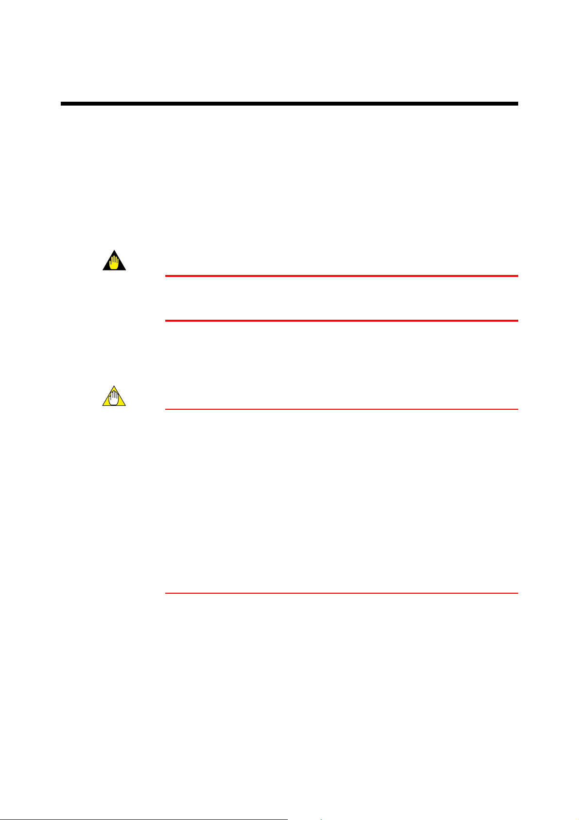
If there will be flammable materials in the vicinity, they should be separated from the
converter top, bottom, left and right sides by a clearance of at least 150 mm, and the
converter covered by a plated steel plate at least 1.43 mm thick, or an uncoated steel
plate of thickness 1.6 mm.
2-1
Page 15
150 mm
Fig. 2.1
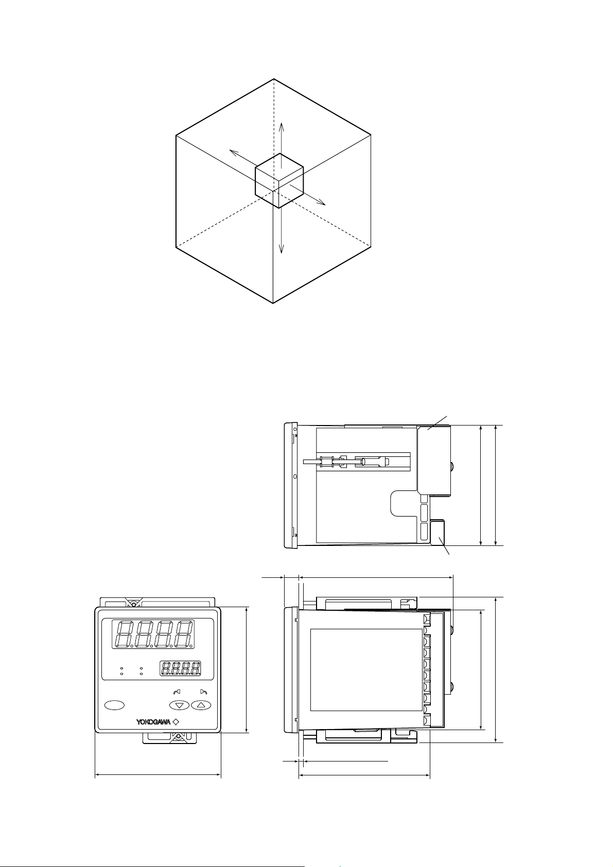
2.3 External Dimensions
• pH Converter
150 mm
150 mm
150 mm
F2.1.EPS
Unit : mm
Shield cover
EXA PH100
pH
S1S2S3
S4
SET CAL MEAS
ENT
CANCEL
96
96
11
118
Panel depth : 1 to 10
100
1-10 4151-60
Terminal cover
91.6
91.6
F003.EPS
92
111
2-2
Fig. 2.2
IM 12B11A01-01E
Page 16

2.4 Panel Cutout Dimensions
2. Preparation for Operation
145 Min.
Fig. 2.3
125 Min.
92
+0.8
0
Unit : mm
+0.8
0
92
IM 12B11A01-01E
2-3
Page 17
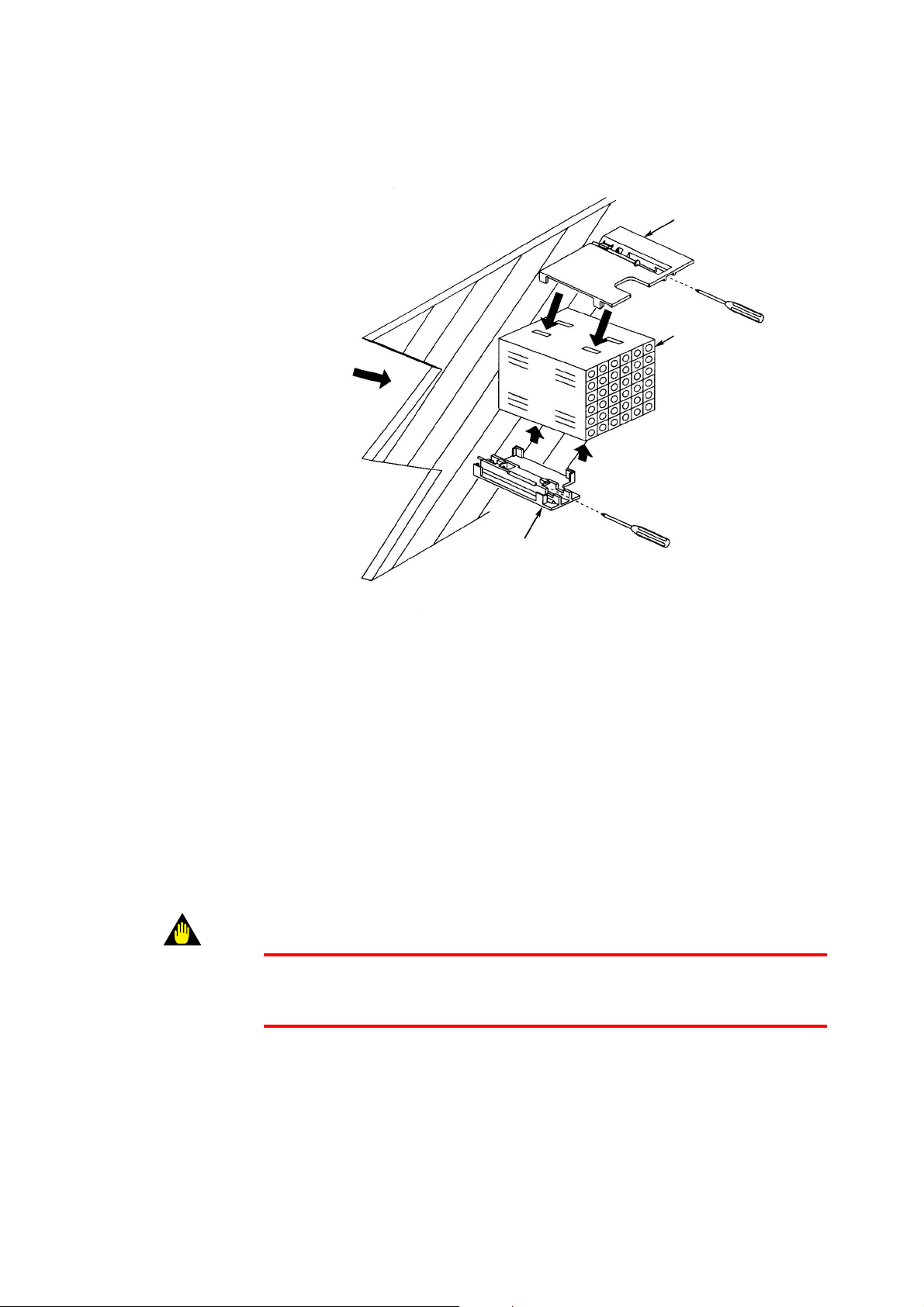
2.5 Mounting
Insert from this
Side of panel
Large brackct (mount at top)
Panel
Terminal board
Insert driver as shown
to tighten bracket
Small bracket (mount at bottom)
Fig. 2.4
Procedure 1
Cut out panel to mount instrument, cut out dimensions are shown on previous page.
Procedure 2
Insert rear of instrument (terminal block side) in panel cutout.
Procedure 3
Mount top and bottom brackets (see figure) to fix instrument to panel.
*When detector output is to be prewired, refer to Sec. 3.4(2)
WARNING
If instrument is a tight fit in cutout, do not force it as case or mounting brackets may be
damaged.
2-4
IM 12B11A01-01E
Page 18
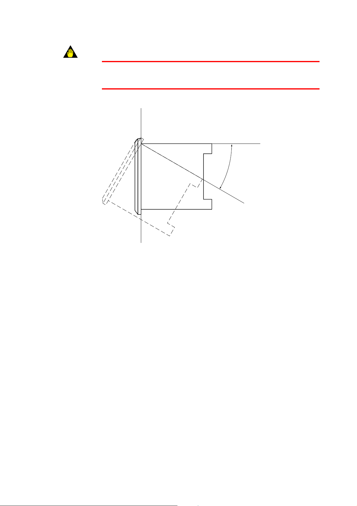
WARNING
The instrument may be installed with the rear inclined at an angle up to 308 below front.
Do not incline with front below rear.
2. Preparation for Operation
Up to 308
Fig. 2.5
F2.5.EPS
IM 12B11A01-01E
2-5
Page 19

2-6
IM 12B11A01-01E
Page 20
3. Wiring
This section explains wiring of the EXA PH100 pH converter.
WARNING
Be sure to turn off power supply, and check with a tester or the like that connected cables
do not have dangerous voltages applied. Do not touch terminals if power may be
applied.
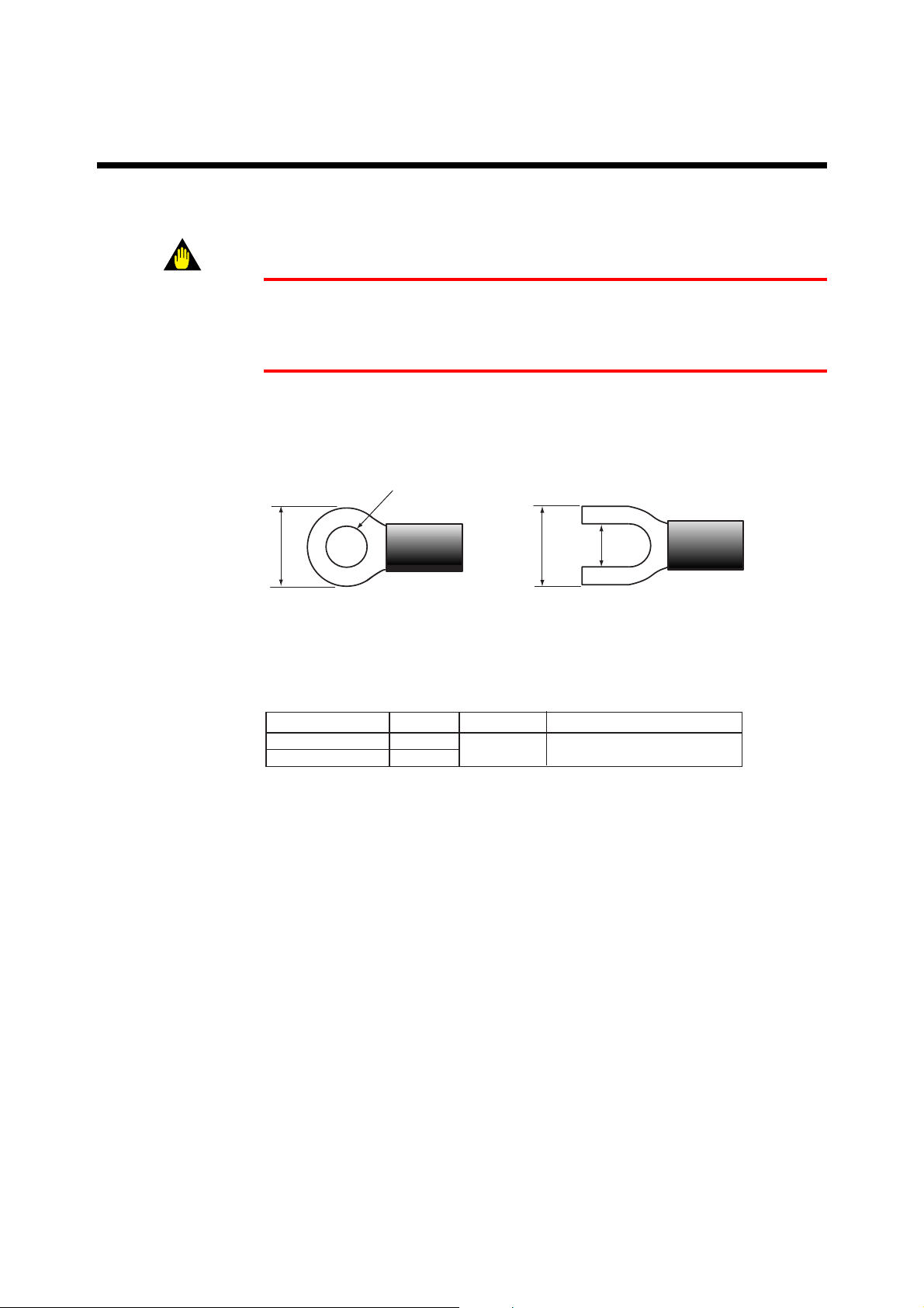
The recommended specifications for wiring terminals are shown below.
Use crimp-on terminals, designed to fit an ISO M3.5 screw, with an insulating sleeve.
3. Wiring
3.7mm\
Up to 7mm
Fig. 3.1
d Recommended terminals
Table 3.1
Maker
Japan AMP Co., Ltd
JST Co., Ltd
model
1.25-YS3A
YD1.25-3.5
For wire size:
0.3~1.65mm
Up to 7mm
3.7mm
Tightening torque
0.8N . m (8 kgf . cm) Up to or Iess
F3.1.EPS
T3.1.EPS
IM 12B11A01-01E
3-1
Page 21
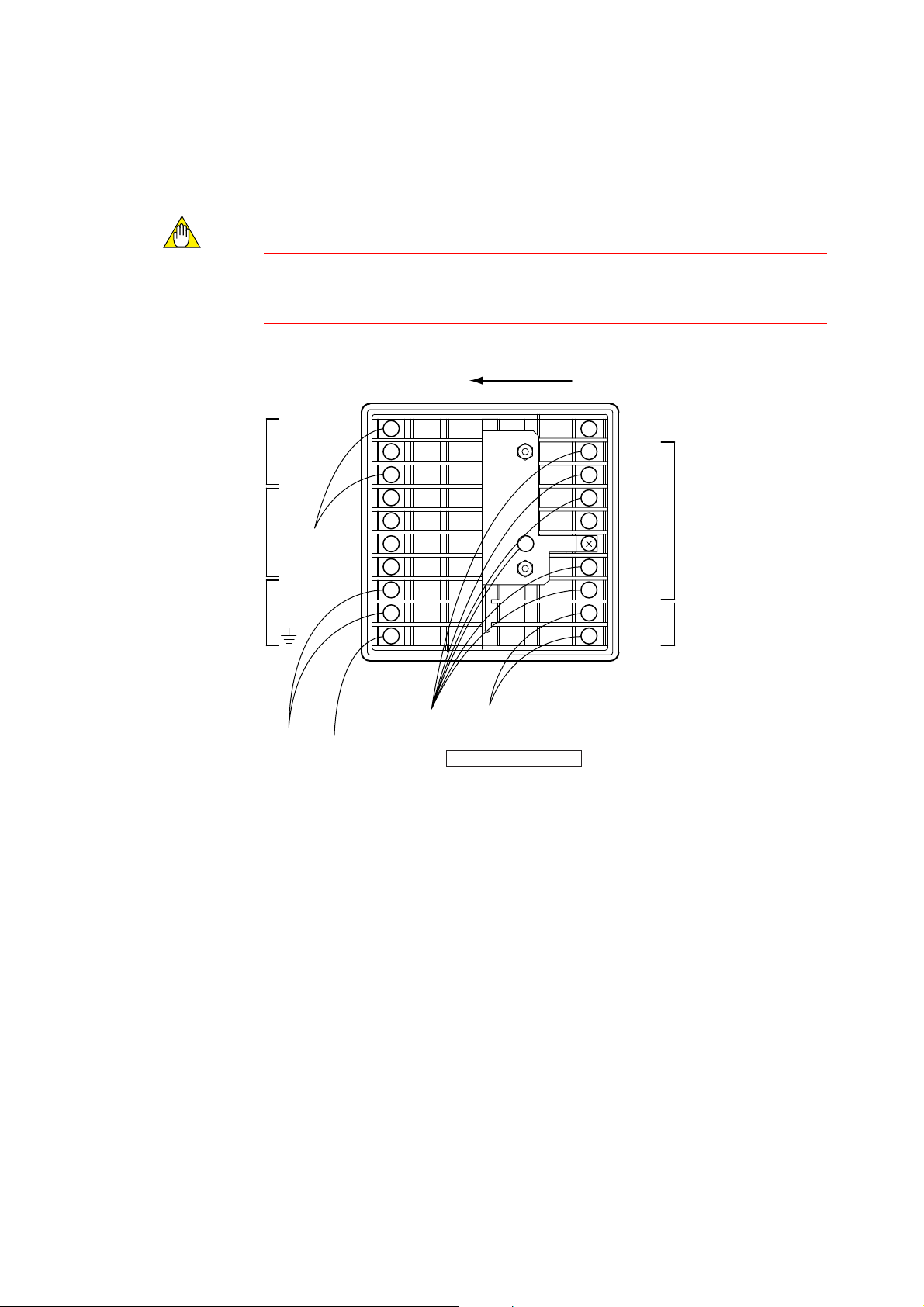
3.1 Pulling in Wiring
When wiring cables to terminals on the rear of the instrument, pull the cables into the
instrument in the direction shown in Fig. 3.2
CAUTION
There’s a terminal wiring diagram on the instrument nameplate on the side of the
instrument.
Pull in cable from left side
Terminal name Terminal name
S1(NC)
S1(NO)
COM1
S2
S3
S4
COM2
L
N
10
1
2
3
4
5
6
7
8
9
16
11
12
13
14
15
17
18
19
20
GE
S
RE
RES
SE
T1
T2
mA (1)
mA (2)
Analog output
cable
Converter rear panel
Power
wiring
Ground
wire
pH sensor
cable
Fig. 3.2 Direction to pull in wiring
F3.2.EPS
3-2
IM 12B11A01-01E
Page 22

3.2 Noise prevention
d Noise sources
The following are typical sources of electrical noise
* Relays and contacts
* Solenoid coil, solenoid valve
* Power lines
* Inductive loads
* Inverters
* Motor commutators
* SCRs used for phase-angle control
* Wireless transmitters
* Welding equipment
* High-voltage ignition systems
d Noise prevention
When wiring, take the following precautions to minimize the effects of noise:
* Keep input circuit wiring as far as possible from power or ground wiring.
* Shielded wires, with single-point grounding, are effective for minimizing pickup of
static electric fields.
* Twisted pair wire is effective in minimizing inductive noise pickup.
3. Wiring
IM 12B11A01-01E
3-3
Page 23
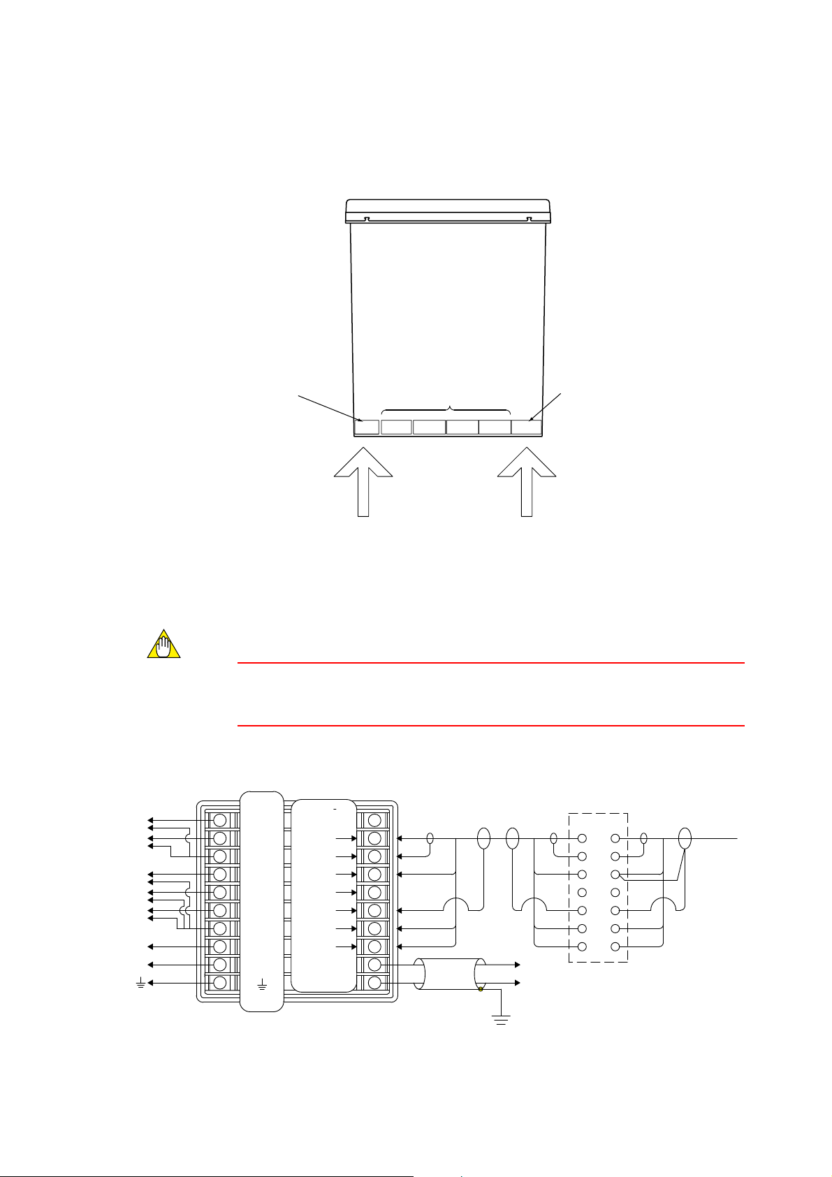
3.3 Wiring Terminal Diagram
There are wiring terminals on the rear of the PH100 converter. Wire to terminals 1 to 10
and terminals 11 to 20 as shown in Fig. 3.3. The terminal block cannot be removed.
Row of terminals
numbered 1 to 10
from top to bottom
Fig. 3.3 Cable wiring position
(1) When intermediate terminal box is used
CAUTION
Terminal size is ISO M3.5. There’s a terminal wiring diagram on the instrument
nameplate on the side of the instrument.
Row of terminals
numbered 11 to 20
Not used
1-10
Contact output and power wiring pH sensor and Analog output cable
31-40 21-30
PH100 Top view
11-2051-61 41-50
from top to bottom
F3.3.EPS
Contact
output 1(NC)
Contact
output 1(NO)
Contact
output 2
Contact
*3)
output 3
Contact
*3)
output 4
Power
supply
L
N
Ground to earth
(grounding resistance
100V or less)
Note : Terminal numbers are indicated on the label side of the converter.
3-4
Converter Rear View
10
1
2
3
4
5
6
7
8
9
Terminal
name
S1(NC)
S1(NO)
COM1
S2
S3
S4
COM2
L
N
Terminal
name
GE
S
RE
RES
SE
T1
T2
mA(1)
mA(2)
11
12
13
14
15
16
17
18
19
20
Extension cable
WF100-PH *2)
Output signal
Shield
Ground to earth (grounding resistance 100V or less)
Fig. 3.4 Wiring diagram when intermediate terminal box is used
Terminal box
WTB100-PH *1)
GE
S
RE
RES
SE
T1
T2
pH sensor
F3.4E.EPS
IM 12B11A01-01E
Page 24

Contact output (NC)
Contact output (NC)
Contact output 2
*3)
Contact output 3
*3)
Contact output 4
Power
supply
Ground to earth
L
N
(grounding resistance
100V or less)
(2) When intermediate terminal box is not used
CAUTION
Terminal size is ISO M3.5. There’s a terminal wiring diagram on the instrument
nameplate on the side of the instrument.
1
2
3
4
5
6
7
8
9
10
Terminal
(contact)
S1(NC)
S1(NO)
COM1
S2
S3
S4
COM2
L
N
Converter rear view
Terminal
name
GE
S
RE
RES
SE
T1
T2
mA (1)
mA (2)
3. Wiring
11
12
13
14
15
16
17
18
19
Output signal
20
Shield
Ground to earth
(grounding resistance 100V or less)
pH Sensor
F3.5.EPS
Fig. 3.5 Wiring diagram when intermediate terminal box is not used
*1) Intermediate terminal box WTB100 is used when pH converter and pH sensor
are far apart.
*2) Extension cable WF100 is used when pH converter and pH sensor are far apart.
*3) When only two contact outputs are specified, contact outputs 3 and 4 (S3 and S4)
are not used. When four contact outputs are used, S3 and S4 share the same
common lead (COM2).
IM 12B11A01-01E
3-5
Page 25

Table 3.2 Terminal wiring example
Terminal no. Signal name Signal description
1
2
3
4
5
6
7
8
9
10
11
12
13
14
15
16
17
S1(NC)
S1(NO)
COM1
S2
S3
S4
COM2
L
N
2
GE
S
RE
RES
SE
T1
Contact output 1 (relay contact) NC
Contact output 1 (relay contact) NO
Contact output 1 (common)
Contact output 2 (relay contact)NO
Contact output 3 (relay contact) NO
Contact output 4 (relay contact) NO
Contact output 2 (common) (shared by S2,S3 & S4)
Power line L
Power line N
Ground
Reserved
Glass electrode input terminal
Glass electrode shield terminal
Reference electrode input terminal
Reference electrode shield terminal
Ground electrode (cable shield) terminal
Temperature input terminal
18
19
20
CAUTION
Figures 3.4 and 3.5 seem to indicate that cable can be pulled in from right hand side, but
in fact cable can only be pulled in from left hand side as described in Sec. 3.1
T2
mA(1)
mA(2)
Temperature input terminal
Analog output terminal (1)
Analog output terminal (2)
T3.2.EPS
3-6
IM 12B11A01-01E
Page 26

3.4 pH detector wiring
This section describes connection of the Model PH10FP KCl Refillable pH sensor or the
Model PH10RP KCl Replenish-free pH sensor to the EXA PH100 pH converter.
CAUTION
For a description of how to connect these sensors via extension cable and intermediate
terminal box, refer to IM 12B11E01-01E for the EXA WTB100 intermediate terminal
box, and refer to IM 12B11F01-01E for the EXA WF100 extension cable.
The procedure for connecting a sensor to the EXA PH100 pH converter is as follows:
(1) Loosen the two holding screws to remove the shielding cover (which covers the
terminals used for connecting a pH detector) from the rear of the EXA PH100 pH
sensor.
(2) Connect the pH sensor (detector) by cable to the terminals. The color coding of the
wires in the cable and the corresponding terminals that they are connected to are
listed below:
3. Wiring
pH converter terminal no. Cable core color code for
1
PH10FP and PH10RP pH sensors
11 Do not use
12 Red (GE)
13 Yellow (S)
14 Brown (RE) two wires
15 Do not use
16 Green (SE)
17 White (T1)
18 Black (T2)
pH converter terminal no. Cable core color code for
2
PH8EFP and PH8ERP pH detectors
11 Do not use
12 Red (GE)
13 Yellow (S)
14 Brown (RE)
15 Do not use
IM 12B11A01-01E
16 Green (SE)
17 White (T1)
18 Black (T2)
CAUTION
When using the PH8EFP or PH8ERP which have pin terminals, be sure to replace the
SE pin terminal with a forked terminal, as if you use the pin terminal is prone to pulling
out, resulting in unreliable measurements.
3-7
Page 27

pH converter terminal no. Cable core color code for
3
CAUTION
When using the PH8EFG or PH8ERG which have pin terminals, be sure to replace the
SE pin terminal with a forked terminal, as if you use the pin terminal is prone to pulling
out, resulting in unreliable measurements. You can’t measure temperature by connecting
… to T1, T2 -- use manual temperature compensation.
PH8EFG and PH8ERG pH detectors
11 Do not use
12 Red (GE)
13 Yellow (S)
14 Brown (RE)
15 Do not use
16 Green (SE)
17 White (T1)
18 Black (T2)
pH converter terminal no. Cable core code for FU20 pH detectors
4
CAUTION
FU20 cable core numbers do not agree with converter terminal numbers, so care is
required.
(3) Use wiring clips to hold the pH sensor cable in place.
(4) Replace the shielding cover removed instep (1) above. Be careful not to pinch the
sensor wiring with the cover when replacing it.
11 Do not use
12 15 (GE)
13 16 (S)
14 13 (RE)
15 Do not use
16 14 (SE)
17 11 (T1)
18 12 (T2)
3-8
IM 12B11A01-01E
Page 28

3.5 Wiring cable to intermediate terminal box
When the EXA PH100 pH converter is separated by a distance from the pH detector,
use the EXA WTB100 terminal box and EXA WF100 extension cable to connect them.
3.6 Output Signal Cable Wiring
DANGER
To minimize the danger of shock, before connecting or disconnecting wires be sure to
confirm that the pH converter power is OFF.
The output signal wiring from the PH100 converter connects to recorders or the like.
Use two-core shielded cable for this wiring.
(1) Connect connecting cable to the terminals. Be sure to use the recommended termi-
nals and be sure that they are the correct size for the cable copper core diameter.
(2) As shown in Figures 3.4 and 3.5 of Section 3.3, ground to earth and ground connec-
tion at one point only.
3. Wiring
3.7 Contact output wiring.
3.7.1 Wiring when S1 is used
A terminal cover is fitted to reduce the risk of electric shock when power is applied.
When connecting contact output wiring, you need to loosen the two cover screws to
remove the cover. After completing the wiring, take care not to forget to replace the
cover.
Load
Load
Fig. 3.6 Relay contact output wiring
* If you want to connect a load which exceeds the contact rating (voltage rating 240 V
AC, current rating 3A resistive load, 30 VDC 3A resistive load) then you need to use
a slave relay.
* If you connect an inductive load like a solenoid valve or slave relay then in parallel
with the contacts you should connect a CR filter (when switching AC) or a diode
(when switching DC), or contact live may be affected.
Terminal no.
NC
1
NO
2
COM
3
F3.6.EPS
IM 12B11A01-01E
3-9
Page 29

WARNING
* Be sure to disconnect power before removing the terminal cover. Since there is the
danger of shock, turn off power and confirm that terminals are not live before wiring.
Under no circumstances should terminals be touched when power is applied.
Recommended CR filters
Table 3.3
Maker Models
MATSUO Electric co.,Ltd
SHIZUKI Electric co.,Ltd
RUBYCON Corporation
• For an DC relay
Instrument
Fig. 3.7
CR UNIT 953, 955 etc.
SKV, SKVB etc.
CR-CFS, CR-U etc.
Relay (coil rating
must not exceed converter contact rating)
T3.3.EPS
External DC source
R
Diode (mount directly on
relay coil terminals or socket)
F3.7.EPS
3-10
• For an AC relay
Instrument
Fig. 3.8
External AC source
R
CR filter (mount directly on
relay coil terminals or socket)
Relay (coil rating
must not exceed con
veter contact rating)
F3.8.EPS
IM 12B11A01-01E
Page 30

3. Wiring
3.7.2 Wiring for S2 (for two-contact-output case) or S2, S3 and S4 (four-contact output case)
A terminal cover is fitted to reduce the risk of electric shock when power is applied.
When connecting contact output wiring, you need to loosen the two cover screws to
remove the cover. After completing the wiring, take care not to forget to replace the
cover.
(1) If you want to connect a load which exceeds the contact rating (voltage rating 240 V
AC, current rating 3A resistive load, 30 VDC 3A resistive load) then you need to use
a slave relay as shown in Sec. 3.7.1.
(2) If switching a very small current, then -- if possible – connecting a bleeder resistor in
parallel with the relay (or the like) that is the load, can improve contact reliability.
(3) If you connect an inductive load like a solenoid valve or slave relay then in parallel
with the contacts you should connect a CR filter (when switching AC) or a diode
(when switching DC), or contact life may be affected. Contact life is typically at
least 10,000 switching operations with a resistive load.
(4) Use the recommended terminals to terminate connecting cables, and make sure that
they are the correct size to match the cable core diameter.
Terminal no.
S2
4
Load
Fig. 3.9
Load
S3
S4
Load
COM
5
6
7
F3.9.EPS
IM 12B11A01-01E
3-11
Page 31

3.8 Power and Ground Wiring
* Power: This wiring should connect a power source of the correct voltage and fre-
quency to the EXA PH100 pH Converter. The power wiring should be heavy vinyl
sheath cable rated at 600V (specifications equivalent to JIS C 3307).
* Ground: Ground to earth (ground resistance 100 ohms or less). Use a sufficiently
heavy cable (cross sectional area of 2 mm2 or greater).
* Use the recommended terminals to terminate connecting cables, and make sure that
they are the correct size to match the cable core diameter.
A terminal cover is fitted to reduce the risk of electric shock when power is applied.
When connecting contact output wiring, you need to loosen the two cover screws to
remove the cover. After completing the wiring, take care not to forget to replace the
cover.
WARNING
* Be sure to disconnect power before removing the terminal cover. Since there is the
danger of shock, turn off power and confirm that terminals are not live before wiring.
Under no circumstances should terminals be touched when power is applied.
CAUTION
The EXA PH100 pH converter does not have a power switch built in. You should add
an on-off switch with two poles (to disconnect both sides of the power line).
3-12
IM 12B11A01-01E
Page 32

WARNING
Any errors in power and ground wiring may damage the converter. Before applying
power to the converter, be sure to check the wiring.
EXA PH100 pH converter
Terminal no.
1
2
3
4
5
6
1
S1(NC)
S1(NO)
COM1
S2
S3
S4
~
10
3. Wiring
Power
Fig. 3.10
Switch (provided by user)
Power wiring
10
COM2
7
L
8
N
9
F3.10.EPS
IM 12B11A01-01E
3-13
Page 33

3-14
IM 12B11A01-01E
Page 34

4. Overview of Operation Panel
4. Overview of Operation Panel
4.1 Overviews of names and functions of operation panel
keys
1
Measured value display
4-digit display
When measuring: pH value is displayed
When measuring or calibrating: numerical
data and alphanumerics
Set/Ent key
m key. key
4
Status display
Four LEDs (When 2 contact outputs specified : two LEDs)
*Display contact output status (lit when operated)
Fig. 4.1
2
Auxiliary display
4-digit display
When measuring: temperature display
(selectable)
When setting: parameters
3
Keypad area
Three keys:
*SET/ENT key
* m key
* . key
F4.1.EPS
IM 12B11A01-01E
4-1
Page 35

4.2 Key Operation
On the EXA PH100 front panel there are three keys for screen/mode switching and data
entry.
CANCEL
(A) (B) (C)
SET CAL MEAS
ENT
key
F4.2.EPF
Fig. 4.2 Layout of three keys on front panel
Main uses of these keys are as follows:
(A) SET/ENT key: used to confirm mode changes and data settings
* From the measurement panel, if you press it continuously for at least three seconds
then the data setting screen is displayed.
SET
Press for 3 sec. and
ENT
Fig. 4.3
(B) ( ) key: Use to select different menu item or reduce data setting value.
* Pressing this key for at least three seconds switches to the calibration screen.
SET (data entry screen) is displayed.
F4.3.EPS
CAL
Press for 3 sec. and CAL
(calibration screen) is displayed.
F4.4.EPS
Fig. 4.4
(C) ( ) key: Use to select different menu item or increase data setting value.
* Pressing this key for at least three seconds from calibration or data setting top
screen switches back to the measurement screen.
MEAS
Press for 3 sec. and MEAS
(measurement screen) is displayed.
F4.5.EPS
Fig. 4.5
(B) + (C) Pressing both ( ) and ( )) screen simultaneously cancels operations
4-2
IM 12B11A01-01E
Page 36

4.3 Switching display screens
EXA PH100 has three menu screens: measurement, calibration and data setting screens.
The screen transition diagram is shown below.
Power ON
Initial display (4?4?1)
4. Overview of Operation Panel
Measurement screen
Press SET/ENT key
for three seconds
Data setting screen
Fig. 4.6
(4?4?2)
(4?4?4)
Press ( ) key for 3 seconds
Press ( ) key for 3 seconds
Press ( ) key for 3 sec.
Calibration screen
(4?4?3)
F4.6.EPS
IM 12B11A01-01E
4-3
Page 37

4.4 Display screen examples
4.4.1 Initial display
Display when converter is normal.
(1) All LEDs are lit when converter is powered on.
Fig. 4.7 All LEDs lit
(2) Then all LEDs turn off.
4-4
Fig. 4.8 All LEDs off
IM 12B11A01-01E
Page 38

(3) Measurement screen is displayed
4. Overview of Operation Panel
Fig. 4.9 Measurement screen with temperature display
4.4.2 Measurement screen
1) Measurement screen
* Measurement display: Displays pH value.
Decimal point is fixed; two digits below the decimal point.
* Auxiliary display:
When temperature display functions are provided, the temperature and units (C
for 8C, F for 8F) are displayed. When temperature display functions are not
provided, nothing is displayed. (The initial setting is for no temperature display).
pH display - up to 2 digits below decimal point
When temperature display is provided
IM 12B11A01-01E
F4.7.EPS
Fig. 4.10
4-5
Page 39

4.4.3 Calibration screen
(1) From Measurement screen
Press ( ) key for 3 sec. to transfer to Calibration screen
Press for at less 3 sec.
Fig. 4.11 Measurement screen
(2) Calibration screen
4-6
Fig. 4.12 Calibration screen (for Autocalibration case)
Press ( ) for at less 3 sec. to return to Measurement screen
IM 12B11A01-01E
Page 40

4.4.4 Setting screen
4. Overview of Operation Panel
(1) Measurement screen display
Press SET/ENT screen for at least 3 sec. to transfer to Setting screen.
Press for at less 3 sec.
Fig. 4.13 Measurement screen
(2) Setting screen
IM 12B11A01-01E
Fig. 4.14 Setting screen
Press ( ) for at less 3 sec. to return to Measurement screen
4-7
Page 41

4-8
IM 12B11A01-01E
Page 42

5. Operation
5.1 Start up
5.1.1 Check wiring
Check that all wiring is correct (refer to Sec. 3.3)
5.1.2 Start up pH converter
Apply power (100 to 240V AC 6 10% 50/60Hz) to EXA PH100 pH converter.
5.1.3 Data setting
Set the following parameters -- (1) analog output parameter, (2) calibration parameters,
(3) alarm settings, and (4) other parameters -- in the order listed, to enable desired
operation for process pH control:
(1) Analog output parameters
This screen is for user setting of analog-output-related settings
5. Operation
(2) Calibration parameters
This screen is for user setting of calibration-related settings
(3) Alarm parameters
This screen is for user setting of alarm-related settings
(4) Other parameters
This screen is for user setting of parameter settings other than (1) to (3) above.
Note
See Sec. 4 “Overview of Operation Manual” and table of LED display symbols in
preface to this manual.
IM 12B11A01-01E
5-1
Page 43

(1) Analog output parameter setting screen (Ao.PA displayed at top of screen)
This screen is for user setting of analog-output-related settings. A list of menu
options on this screen is shown below:
Table 5.1
Name Parameter Setting range Initial value Note
Ao.PA Menu Title NA (not applicable) NA
RL
Range low
limit
22.0 ~ 16.0pH
0.0pH
High & low at
least pH2 apart
RH
M.HLd
H.Ao
F.HLd
Range high
limit
Hold during
Maintenance
Hold output
setting
Hold if
abnormal
22.0 ~ 16.0pH
0 : No Hold
1 : Hold
2 : Set value
2.0 ~ 20.8mA
0 : No Hold
1 : Burn out down scale (2mA)
14.0pH
1 : Hold
2.0
1 : Burn out down scale (2mA)
High & low at
least pH2 apart
T5.1E.EPS
5-2
IM 12B11A01-01E
Page 44

OR100EXA
mV
S1S2S3
S4
SET
ENT
CANCEL
MEASCAL
Measurement screen
5. Operation
Example flow chart for analog output parameter setting is shown below
Press mkey
for 3 esc
Low range limit
High range limit
Press SET/ENT
for 3 sec.
S1S2S3
EXA OR100
S4
Ao.PA flashing
mV
Analog output parameter setting screen
SET/ENT key
Change value with m and . keys
EXA OR100
S1S2S3
mV
S4
SET/ENT key
Change value with m and . keys
EXA OR100
S1S2S3
mV
S4
SET/ENT key
S1S2S3
S1S2S3
EXA OR100
S4
EXA OR100
S4
mV
SET/ENT key
rewrites data
mV
SET/ENT key
rewrites data
S1S2S3
Hold during
maintenance
S1S2S3
Hold output
setting
S1S2S3
Hold if
abnormal
Change value with m and . keys
EXA OR100
mV
S4
SET/ENT key
Change value with m and . keys
EXA OR100
mV
S4
SET/ENT key
Change value with m and . keys
EXA OR100
mV
S4
SET/ENT key
S1S2S3
S1S2S3
S1S2S3
EXA OR100
S4
EXA OR100
S4
EXA OR100
S4
mV
SET/ENT key
rewrites data
mV
SET/ENT key
rewrites data
mV
SET/ENT key
rewrites data
Fig. 5.1 Example flow chart for analog output parameter setting
* Note: To cancel, press both ( ) and ( ) simultaneously.
F5.1.EPS
IM 12B11A01-01E
5-3
Page 45

Hame
(2) Calibration parameter setting screen (CAL displayed at top of screen)
This screen is for user setting of calibration-related settings. A list of menu options
on this screen is shown below:
Table 5.2
Parameter Setting range Initial value Note
CAL Menu Title
CL.md Calibration
CL.Po Calibration
CL.2P
CL.1P
CL.tb
method
points
Two-point CAL
std. liquid
One-point CAL
std. liquid
Std. liquid
cal.table
NA (not applicable)
0 : Autocalibration
1 : Manual calibration
0 : One-point
1 : Two-point calibration
0 : pH7, pH4
1 : pH9, pH7 (US: pH 10, pH7)
2 : pH9, pH4 (US: pH 10, pH4)
0 : pH7
1 : pH4
2 : pH9 (US: pH 10)
0 : JIS, NIST
1 : US
2 : DIN
NA
0 : Autocalibration
1 : Two-point calibration
0 : pH7, pH4
0 : pH7
0 : JIS, NIST
T5.2.EPS
5-4
IM 12B11A01-01E
Page 46

Example flow chart for calibration parameter setting is shown below
pH
EXA PH100
S1S2S3
S4
pH
EXA PH100
ENT
S1S2S3
S4
SET CAL MEAS
CANCEL
pH
EXA PH100
S1S2S3
S4
pH
EXA PH100
S1S2S3
S4
pH
EXA PH100
S1S2S3
S4
pH
EXA PH100
S1S2S3
S4
pH
EXA PH100
S1S2S3
S4
pH
EXA PH100
S1S2S3
S4
S4S3S2
S1
PH100EXA
pH
pH
EXA PH100
S1S2S3
S4
pH
EXA PH100
S1S2S3
S4
pH
EXA PH100
S1S2S3
S4
pH
EXA PH100
S1S2S3
S4
F5.2.EPS
Measurement screen
Perss m key
for 3sec.
Press SET/ENT
for 3 sec.
Perss m key
for 3sec.
Perss . key Perss m key
CAL flashing
Calibration parameter setting screen
SET/ENT key
Change value with m and . keys
SET/ENT key
SET/ENT key
CAL method
setting
CAL points
setting
SET/ENT key
rewrites data
Change value with m and . keys
Change value with m and . keys
SET/ENT key
rewrites data
SET/ENT key
Std. liquid
for 2- point CAL
Change value with m and . keys
Std. liquid
for 1- point CAL SET/ENT key
SET/ENT key
rewrites data
Change value with m and . keys
Table type
for Std.liquid CAL SET/ENT key
SET/ENT key
rewrites data
SET/ENT key
rewrites data
5. Operation
IM 12B11A01-01E
Fig. 5.2 Example flow chart for calibration parameter setting
* Note: To cancel, press both ( ) and ( ) simultaneously.
5-5
Page 47

(3) Alarm parameter setting screen (Alrm displayed at top of screen)
This screen is for user setting of alarm data. A list of menu options on this screen is
shown below:
Table 5.3
Hame Parameter Setting range Initial value Note
Alrm top menu NA (not applicable) NA
S1 S1 0: high limit alarm
HY1
dLY1 S1 delay time 0-200 seconds 0
S2 S2
HY2
dLY2
S3
HY3 S3 hysteresis 0.0-4.0 pH 0.1 pH
dLY3 S3 delay time 0-200 seconds 0
S4 S4 0: high limit alarm
HY4 S4 hysteresis 0.0-4.0 pH
dLY4 S4 delay time 0-200 seconds 0
H.A
S1 hysteresis 0.0-4.0 pH 0.1 pH
S2 hysteresis 0.0-4.0 pH
S2 delay time
S3
high limit alarm
1: low limit alarm
2: high high limit alarm
4: high high limit/low low limited alarm
5: abnormal
0: high limit alarm
1: low limit alarm
2: high high limit alarm
4: high high limit/low low limited alarm
5: abnormal
0-200 seconds 0
0: high limit alarm
1: low limit alarm
2: high high limit alarm
4: high high limit/low low limited alarm
5: abnormal
1: low limit alarm
2: high high limit alarm
3: low low limit alarm
4: high high limit/low low limited alarm
5: abnormal
-2.0-16.0pH
0: high limit alarm
1: low limit alarm
0.1 pH
2: high high limit alarm when suffix
3: low low limit alarm
0.1 pH
14.0pH
code is -21,
S3 does not
appear
when suffix
code is -21,
HY3 does not
appear
when suffix
code is -21,
dLY3 does not
appear
when suffix
code is -21,
S4 does not
appear
when suffix
code is -21,
HY4 does not
appear
when suffix
code is -21,
dLY4 does not
appear
L.A
HH.A high high limit alarm
LL.A low low limit alarm
low limit alarm 0.0 pH
5-6
-2.0-16.0pH
-2.0-16.0pH
-2.0-16.0pH
14.0pH
0.0 pH
T5.3.EPS
IM 12B11A01-01E
Page 48

Example flow chart for setting alarm parameters is shown below
EXA PH100
S1S2S3
SET CAL MEAS
ENT
Measurement screen
pH
S4
CANCEL
5. Operation
Press m key
for 3 sec.
Press m key
for 3 sec.
Press . key
for 2 times.
S1 hysteresis
S1 delay time
S2 hysteresis
S2 delay time
S3 hysteresis
Press SET/ENT key
for 3 sec.
EXA PH100
pH
S1S2S3
S4
Press m key
for 2 times.
PH100EXA
pH
S1
S4S3S2
SET/ENT key
Change value with m and . keys
EXA PH100
pH
S1S2S3
S4
S1
SET/ENT key
Change value with m and . keys
EXA PH100
pH
S1S2S3
S4
SET/ENT key
Change value with m and . keys
EXA PH100
pH
S1S2S3
S4
SET/ENT key
Change value with m and . keys
EXA PH100
pH
S1S2S3
S4
S2
SET/ENT key
Change value with m and . keys
EXA PH100
pH
S1S2S3
S4
SET/ENT key
Change value with m and . keys
EXA PH100
pH
S1
S2S3S4
SET/ENT key
Change value with m and . keys
EXA PH100
pH
S1S2S3
S4
S3
SET/ENT key
Change value with m and . keys
EXA PH100
pH
S1S2S3
S4
SET/ENT key
Ao.PA flashing
ALrm flashing
Alarm parameter setting screen
EXA PH100
S1
S2S3S4
SET/ENT key
rewrites data
EXA PH100
S1S2S3
S4
SET/ENT key
rewrites data
EXA PH100
S1S2S3
S4
SET/ENT key
rewrites data
EXA PH100
S1S2S3
S4
SET/ENT key
rewrites data
EXA PH100
S1
S2S3S4
SET/ENT key
rewrites data
EXA PH100
S1S2S3
S4
SET/ENT key
rewrites data
EXA PH100
S1S2S3
S4
SET/ENT key
rewrites data
EXA PH100
S1
S2S3S4
SET/ENT key
rewrites data
Change value with m and . keys
S3 delay time
S4
S4 hysteresis
EXA PH100
pH
S1S2S3
S4
SET/ENT key
Change value with m and . keys
EXA PH100
pH
S1S2S3
S4
SET/ENT key
Change value with m and . keys
EXA PH100
pH
S1S2S3
S4
SET/ENT key
Change value with m and . keys
EXA PH100
pH
S1
S2S3S4
SET/ENT key
Change value with m and . keys
EXA PH100
pH
S1S2S3
S4
SET/ENT key
Change value with m and . keys
EXA PH100
pH
S1
S2S3S4
SET/ENT key
Change value with m and . keys
EXA PH100
pH
S1S2S3
S4
SET/ENT key
Change value with m and . keys
EXA PH100
pH
S1
S2S3S4
SET/ENT key
pH
pH
pH
pH
S4 delay time
pH
High limit alarm
pH
Low limit alarm
pH
High high limit alarm
pH
Low low limit alarm
EXA PH100
S1S2S3
S4
EXA PH100
S1S2S3
S4
EXA PH100
S1
S2S3S4
EXA PH100
S1S2S3
S4
EXA PH100
S1
S2S3S4
EXA PH100
S1S2S3
S4
EXA PH100
S1
S2S3S4
EXA PH100
S1
S2S3S4
pH
SET/ENT key
rewrites data
pH
SET/ENT key
rewrites data
pH
SET/ENT key
rewrites data
pH
SET/ENT key
rewrites data
pH
SET/ENT key
rewrites data
pH
SET/ENT key
rewrites data
pH
SET/ENT key
rewrites data
pH
SET/ENT key
rewrites data
IM 12B11A01-01E
F5.3.EPS
Fig. 5.3 Example flow chart for setting alarm parameters when four contacts
output specified
Note: To cancel, press both ( ) and ( ) simultaneously.
5-7
Page 49

(4) Other parameter setting screen (otHr displayed at top of screen)
This screen is for user setting of parameters for other measurements. A list of menu
options on this screen is shown below
Table 5.4
Name Parameter Setting range Initial value Note
otHr
dsP.t
UnIt
t.SnS
SEL.t
SEt.t
t.CAl
Menu Title
temperature in display
Temperature unit
RTD type
temperature compensation
temperature setting
temperature calibration
(1-point calibration)
NA (not applicable) NA
0: OFF
1: ON
0: 8C
1: 8F
0: Pt1000
1: Other
0: automatic (temperature sensor)
1: manual (setting)
-10.0~110.08C
(14.0~230.08F)
-15.0~115.08C
(5.0~239.08F)
0: OFF
0: 8C
0: Pt1000
0: automatic (temperature sensor)
25.08C
(77.08F)
For reference.
temperature is displayed when this
parameteris displayed.
The temperature is not updated
automatically
Other depends on the
suffix code
Effective when
SEL.t is 1
Please input the actual
temperature of the
measurement liquid
Effective when SEL.t
is 0.
d.InS
InSP menu display
fliag setting
0: no display
1: display
0: no display Alwaus set 0
When the power is turned
off, the setting become
0
T5.4.EPS
5-8
IM 12B11A01-01E
Page 50

EXA PH100
S1S2S3
S4
SET CAL MEAS
ENT
CANCEL
Measurement screen
5. Operation
Example flow chart for setting other measurement parameters is shown below
pH
Press m key
for 3 sec.
Press m key
for 3 sec.
Press . key
for 3 times
S1S2S3
S1S2S3
S1
Temperature display setting
S1
Temperature unit setting
S1
Temperature RTD type setting
EXA PH100
S4
EXA PH100
S4
SET/ENT key
PH100EXA
S4S3S2
SET/ENT key
PH100EXA
S4S3S2
SET/ENT key
PH100EXA
S4S3S2
SET/ENT key
Press SET/ENT
for 3 sec.
pH
Ao.PA flashing
Press m key
for 3 times.
otHr flashing
pH
Other parameter setting screen
Change value with m and . keys
pH
Change value with m and . keys
pH
Change value with m and . keys
pH
Change value with m and . keys
PH100EXA
S4S3S2
SET/ENT key
rewrites data
pH
Temperature
compensation
S1
PH100EXA
S4S3S2
pH
SET/ENT key
rewrites data
Temperature setting
S1
PH100EXA
S4S3S2
pH
SET/ENT key
rewrites data
Temperature
calibration
InSP menu dispisplay
on/off Flag setting
S1
PH100EXA
S1
pH
S4S3S2
SET/ENT key
Change value with m and . keys
PH100EXA
S1
pH
S4S3S2
SET/ENT key
Change value with m and . keys
PH100EXA
S1
pH
S4S3S2
SET/ENT key
Change value with m and . keys
PH100EXA
S1
pH
S4S3S2
PH100EXA
S4S3S2
pH
SET/ENT key
rewrites data
S1
PH100EXA
S4S3S2
pH
SET/ENT key
rewrites data
S1
PH100EXA
S4S3S2
pH
SET/ENT key
rewrites data
S1
PH100EXA
S1
pH
S4S3S2
SET/ENT key
SET/ENT key
rewrites data
IM 12B11A01-01E
F5.4.EPS
Fig. 5.4 Example flow chart for setting other measurement parameters
Note: To cancel, press both ( ) and ( ) simultaneously.
5-9
Page 51

5.1.4 Temperature Calibration
The EXA PH100 PH converter is used with a pH sensor, and the resistance of the
cabling between them will vary depending on the length of the cable. When Yokogawa’s
PH10FP or PH10RP are used, the cable length is selectable – it may be any of 3 m, 5 m,
or 10 m. When the WTB100 intermediate terminal box is used with the special WF100
extension cable, the cable length may be increased up to 50 m. For accurate temperature
compensation, one time temperature calibration (to compensate for the resistance of the
cable between converter and detector) after installation is recom- mended.
Procedure for Temperature Compensation
Temperature compensation should be performed with the measured solution as near as
possible to the normal temperature of measurement. To minimize temperature change
during measurement, you should prepare at least 4 liters of solution. You also need a
thermometer to measure the temperature of the solution. Temperature calibration uses
the t.CL (Temperature Calibration) setting screen described in Section 5.1.3 (4) Other
Parameters.
The pH detector (immersed up to the liquid junction) and thermometer should be placed
in the solution to be used for temperature calibration. For best accuracy, leave the
detector until its temperature has stabilized (this usually takes about two minutes) before
reading the thermometer, setting that temperature into the conductivity converter, and
calibrating.
Temperature calibration can be performed in the range -15˚C to +115˚C, and the
compensation value (pH detector measured temperature minus thermometer measured
temperature) should be within the range -20˚C to +5˚C.
5.1.5 Calibration with Standard Liquid
The emf of the glass electrode varies a little between electrodes. Before stareting normal
operation, calibrate with standard solution.
The emf of the electrode will also vary if it gets dirty or as the electrode ages, so
recalibration needs to be performed periodically at frequent enough intervals to keep
error within rated tolerance.
The procedure for calibration with standard liquid is described in Sec. 6.
5-10
IM 12B11A01-01E
Page 52

5.2 Test Operation
To check if operation of the EXA PH100 pH converter is normal, monitor it in test
operation mode for a while.
5.3 Normal operation
From the parameter setting screen, press the ( ) key for at least 3 seconds to return to
the measurement screen.
Apart from when changing settings or calibrating with standard solution, during normal
operation there should be no need for operating this machine.
If an error message is displayed or the output scales out, refer to Sec. 8 for troubleshooting. please make the cause be clear by following the on and treat immediately.
Also, please be sure to perform the daily checks and maintenance described in Sec. 7 in
order to maintain reliable operation.
5.4 Stopping and Restarting Operation
5. Operation
After changing settings, be sure to wait at least 2 seconds before turning off the power.
In other cases, no special precautions are required.
To stop operation, simply turn off the power supply.
To restart operation, simply restore power and parameter values remain the same as
before the power failed.
IM 12B11A01-01E
5-11
Page 53

5-12
IM 12B11A01-01E
Page 54

6. Calibration with standard solution
6. Calibration with standard solution
The emf characteristics of pH electrodes vary between electrodes, and vary with electrode aging The variability of pH detectors that are used only for short periods can be
particularly high. The variability of pH detectors that are used only occasionally for
short periods can be particularly high. So there is a need for electronic circuitry to
perform automatic compensation of pH.
Calibration with standard solution involves measuring the pH of standard solution of
known pH, and adjusting the pH meter to show the correct pH value.
Calibration with standard solution of the EXA PH100 pH converter can be either
automatic calibration using standard solutions of two predetermined pH values chosen
from pH 4, 7, and 9 (JIS), and manual calibration using arbitrary standard solution.
6.1 Important issues relating to calibration with standard
solution
Standard solution/
temperature 8C
pH4
pH7
pH9
(1) Be careful to use the standard solution marked with the correct pH.
If the pH standard solution has deteriorated and its pH changed, calibration will not
be accurate.
Note: when automatic calibration is used, choose two standard solutions from those
(pH4, pH7and pH9) shown in Table 6.1.
(2) If the temperature of the standard solution is changing, the measured pH value will
not stabilize. At calibration time, keep the standard solution at constant temperature.
(3) During auto calibration, do not touch ENT or ( ), ( ) keys as calibration values
may be affected.
Table 6.1 JIS Z8802 standard solution
0 5 10 15 20 25 30 35 40 45 50 55 60 70 80 90 95
4.01
4.01
4.00
4.00
4.00
4.01
4.01
4.02
4.03
4.04
4.06
4.08
4.10
4.12
4.16
4.20
6.98
6.95
6.92
6.90
6.88
6.86
6.85
6.84
6.84
6.83
6.83
6.84
6.84
6.85
6.86
6.88
9.46
9.39
9.33
9.27
9.22
9.18
9.14
9.10
9.07
9.04
9.01
8.99
8.96
8.93
8.89
8.85
4.23
6.89
8.83
T6.1.EPS
IM 12B11A01-01E
6-1
Page 55

6.2 Calculations involved in Calibration with Standard
Solution
(1) When performing auto one-point calibration of the EXA PH100 pH converter using
one type of standard solution, use one of the standard solutions (pH4, pH7 or pH9)
and adjust the asymmetry potential so that the calibration curve passes through the
calibration point (see Fig. 6.1).
Calibration curve
pH0
Calibration point for
one-point calibration at pH7
Calibration curve
+mV
-mV
Theoretical value
pH7, 0mV
pH14
Asymmetry potential
Calibration point for
one-point calibration at pH4
pH0
+mV
-mV
Theoretical value
pH7, 0mV
pH14
Asymmetry potential
Fig. 6.1
*) When you measure the pH of solutions that have nearly the same pH as a standard
solution, you can use auto one-point calibration, a simple method of calibration that
gives sufficient accuracy in this case.
2) When using two kinds of standard solution for two-point automatic calibration of the
EXA PH100 pH converter, choose two standard solutions pH4, pH7 or pH9 and
adjust the asymmetry potential and slope so that the calibration curve passes through
the first and second calibration points (Fig. 6.2)
Second calibration point (pH4)
F6.1.EPS
Second calibration point (pH4)
m
pH0
First calibration point (pH7)
Fig. 6.2
+mV
-mV
Theoretical value
pH7, 0mV
pH14
Asymmetry potential
Calibration curve (slope)
F6.2.EPS
6-2
IM 12B11A01-01E
Page 56

6. Calibration with standard solution
3) When using one kind of standard solution for manual calibration of the EXA PH100
pH converter, choose any of the standard solutions and draw the calibration curve
through the calibration point (Fig. 6.3).
calibration curve
+mV
Theoretical value
pH7, 0mV
Theoretical value
calibration point when using arbitrary standard liquid
Fig. 6.3
CAUTION
Calibration point represents the electrode emf corresponding to the pH value of the
standard solution used.
pH0
-mV
pH14
Asymmetry potential
F6.3.EPS
IM 12B11A01-01E
6-3
Page 57

4) When using two kinds of standard solution for manual calibration of the EXA PH100
pH converter, choose two arbitrary standard solutions and adjust the asymmetry
potential and slope so that the calibration chart passes through the first and second
calibration points (Fig. 6.4)
CAUTION
It will need more than a pH difference of at least 2 between pH values of the two kinds
of standard solution.
Second calibration point
+mV
Theoretical value
pH7, 0mV
pH0
Fig. 6.4
pH14
asymmetry potential
first calibration point
-mV
calibration curve (slope)
F6.4.eps
6-4
IM 12B11A01-01E
Page 58

6.3 Preparation
(1) Selection the calibration method
* On the calibration parameter setting screen, select the calibration method: automatic
calibration or manual calibration.
* On the calibration parameter setting screen, select one-point calibration or two-point
calibration. Usually, we recommend two-point calibration.
1) Two-point calibration
Select combination of standard solutions from the following:
* pH7 and pH4
pH9 (pH10*) and pH7
pH9 (pH10*) and pH4
*: if US technical standard solution table selected.
2) One-point calibration
Select standard solution from the following:
pH7
pH4
pH9 (pH10*)
*: if US technical standard solution table selected
* On the calibration parameter setting screen, select the kind of standard solution
calibration table from JIS • NIST standard solution table, US technical standard table,
or DIN standard solution table.
6. Calibration with standard solution
IM 12B11A01-01E
6-5
Page 59

Press m key
for 3 sec.
Press m key
for 3 sec.
Example flow chart for setting of auto calibration (two-point calibration) at pH9 and pH7,
using JIS standard calibration table.
PH100EXA
S1
S4S3S2
ENT
Measurement screen
PH100EXA
S1
S4S3S2
pH
CANCEL
MEASCALSET
Press SET/ENT
for 3 sec.
pH
Ao.PA flashing
m key key
EXA PH100
S1S2S3
S4
Calibreation screen
S1
Calibration method setting
S4S3S2
S1
S4S3S2
Calibration points
m
CAL flashing
pH
SET/ENT key
PH100EXA
Meaning of the parameter
Auto calibration: 0 (initial value)
pH
Manual calibration: 1
SET/ENT key
PH100EXA
*Meaning of the parameter
One-point calibration: 0
pH
Two-point calibration: 1(initial value)
Change value with m and . keys
PH100EXA
pH
S1
S4S3S2
Two-point calibration with standard solution
SET/ENT key
rewrites data
PH100EXA
pH
S1
One-point calibration
with standard solution
S4S3S2
S1
Note: only applies for one-point
calibration, so can leave as is.
PH100EXA
*Meaning of the parameter
pH7 and pH4: 0 (initial value)
pH
pH9 and pH7: 1 <- chande to this setting
S4S3S2
pH9 and pH4: 2
6-6
SET/ENT key
Fig. 6.5
S1
Standard solution calibration
table type
PH100EXA
*Meaning of the parameter
JIS: 0 (initial value)
pH
DIN: 1
S4S3S2
US: 2
F6.5.EPS
IM 12B11A01-01E
Page 60

(2) Preparation for auto calibration
* For two-point calibration, select two types of standard solution from among pH4, pH7
and pH9.
CAUTION
In the US, select two from among pH4, pH7, and pH10.
* For one point calibration, select one type of standard solution from among pH4, pH7
and pH9.
CAUTION
In the US, select one from among pH4, pH7, and pH10.
* Prepare two clean containers of size about 200ml, and water (e.g. pure water) for
washing the pH electrode.
6. Calibration with standard solution
(3) Preparation for manual calibration
* For two-point calibration, select any two of the pH standard solutions. But the two
selected need to differ in pH by at least pH2.
* For one-point calibration, use any one of the pH standard solutions.
Prepare two clean containers of size about 200ml, and water (e.g. pure water) for
washing the pH electrode.
CAUTION
When manual temperature compensation is to be performed, provide a thermometer for
measuring the temperature of the standard solutions.
IM 12B11A01-01E
6-7
Page 61

6.4 Auto calibration with standard solution
6.4.1 Setting parameters for auto calibration
Set parameter for auto calibration as per Fig. 5.2, before starting auto calibration.
6.4.2 Procedure for auto calibration
This section describes, as an example, two-point auto calibration using standard liquids
of pH7 and pH4.
1) On the measurement screen, press ( ) key for 3 seconds to switch to the auto
calibration screen.
Measured value display shows current measured value. For example: “6.86”
Auxiliary display shows “A.CAL”.
2) Wash the pH electrode thoroughly with pure water.
3) Dip the detector head in the first standard solution.
4) Press SET/ENT key.
Auxiliary display: displays types of standard solutions that are set at present, e.g. "4-7".
5) Press SET/ENT key. The auxiliary display will show “CAL7” blinking quickly.
(meaning “beginning pH7 calibration).
*note: you can select the other standard solution first (e.g.: CAL4) by pressing ( ) key,
then second solution will be pH7.
6) press SET/ENT key after selecting the standard solution pH to be measured.
7) if “temperature compensation” setting is “manual” then manually measure and set the
measured temperature of the standard solution.
The measurement display shows measured temperature. The auxiliary display shows
“25C” (18C unit), and the least significant digit blinks. For manual temperature
compensation, set the temperature on the auxiliary display with ( ) and ( ) keys.
8) When you press the SET/ENT key, the measurement display value blinks.
The auxiliary display shows “CAL7”.
9) The converter waits until the measured electrode emf, representing the pH value,
stabilizes, performs temperature compensation and calibrates the first pH value.
The blinking of the measurement display value stops.
”Ent7” is displayed, blinking, in the auxiliary display.
*Note: if you want to repeat calibration with the same standard solution, press ( ) and
( ) keys at the same time (for “cancel”).
10) Press SET/ENT key.
The results of calibration at the first calibration point are displayed.
*Note: until you have finished the calibration (both points, in this case), calibration
results are not reflected in any measurement values.
11) Auxiliary display shows “CAL4”, blinking.
(meaning “start pH4 calibration”)
PH value of standard solution to be clibrated will be display due to setted parameter.
12) wash the pH electrode thoroughly with pure water and dip the detector into the
second standard solution.
13) Press SET/ENT key
For manual temperature compensation (manually set temperature), set the temperature of the standard solution.
Measured value display shows the measured value.
Auxiliary display shows the temperature (in 18C units) used for first calibration
point, with the least significant digit blinking.
14) Use ( ) and ( ) keys to set the temperature on the auxiliary display.
15) Pressing SET/ENT key causes the measurement value on the measurement to blink.
The Auxiliary display shows “CAL4”.
6-8
IM 12B11A01-01E
Page 62

Measurement screen
Press m key
for 3 sec.
SET/ENT key
Temperature
compensation by
Temperature sensor
16) The converter waits until the measured electrode emf, representing the pH value,
stabilizes, performs temperature compensation and calibrates the first pH value.
Measurement value on measurement display stops blinking.
“Ent4” blinks on Auxiliary display.
Note: if you want to repeat calibration with the same standard solution, press ( ) and
( ) keys at the same time (for “cancel”).
17) Press SET/ENT again to start the calibration calculation.
If the calibration results are normal, the auxiliary display shows “Good” (blinking).
If results are abnormal, the auxiliary display shows an error code.
18) Pressing SET/ENT key again reverts to original “ACAL” display. If data is abnormal then the calibration data is updated.
19) To revert the detector to online measurement of the process, press ( ) key for at
least 3 seconds, and the measurement screen reappears.
PH100EXA
pH
S1
S4S3S2
CANCEL
MEASCALSET
ENT
To EXA OH100
Press . key
for 3 sec.
PH100EXA
pH
S1
S4S3S2
SET/ENT key
EXA PH100
pH
S1
S2S3S4
SET/ENT key
You can select pH4 with m key
EXA PH100
pH
S1S2S3
S4
Temperature compensation user setting
EXA PH100
Converter judges the
pH
stability of the emf
S1
S2S3S4
Afer temperature compensation, calibrates pH
Thermoneter
Provide thermoneter
when temperature compen
sation is user setting
You can select pH7 with . key
pH electrode
Wash thoroughly before
placing in standard soln.
EXA PH100
pH
S1S2S3
S4
EXA PH100
pH
S1S2S3
S4
Enter reading of thermometer in
standard solution using m or . keys
EXA PH100
pH
S1
S2S3S4
SET/ENT key
pH7 standard
solution.
SET/ENT key
Temperature
compensation by
Temperature sensor
6. Calibration with standard solution
EXA PH100
Thermometer
Provide thermometer
EXA PH100
S1S2S3
S4
Temperature compensation
user setting
EXA PH100
S1S2S3
S4
After temperature compensation, calibrates pH
EXA PH100
S1S2S3
S4
SET/ENT key
EXA PH100
S1S2S3
S4
SET/ENT key
Press m and . keys together to repeat this calibration step
when temperature compensation is user setting
pH
Measurement value
blinking stops
Auxiliary display blinks
EXA PH100
pH
S1S2S3
S4
Enter reading of thermometer in standard
solution using m or . keys
EXA PH100
pH
S1S2S3
S4
Converter judges the stability of the emf
pH
Measurement value blinking stops
pH
Auxiliary display blinks
Second calibration point result stored in the converter
pH
SET/ENT key
pH electrode
Wash thoroughly before
placing in standard soln.
pH4 standard solution.
EXA PH100
S1S2S3
S4
IM 12B11A01-01E
pH
First calibration point result stored in the converter
Measurement value blinking stops Auxiliary display blinks
SET/ENT key
Pressing m and . key together reverts to the top screen
Fig. 6.6 Two-point auto calibration using standard solution of pH7 and pH4
PH100EXA
pH
S1
S4S3S2
Press m key for 3 sec. to revert to process measurement
PH100EXA
pH
S1
S4S3S2
CANCEL
MEASCALSET
ENT
Measurement screen
F6.6.EPS
6-9
Page 63

Here we describe an example of one-point auto calibration method using a standard
solution of pH7
1) On the Measurement screen, press the ( ) key for three seconds to switch to the
autocalibration screen. The current measurement value is displayed, for example 6.86
The Auxiliary display changes to “A.CAL”
2) Clean the pH electrode with an adequate amount of pure water.
3) Dip the sensor in standard solution.
4) Press the SET/ENT key. The Auxiliary display shows pH of the standard liquid to be
used for calibration, e.g. “7”.
5) Press the SET/ENT key. The Auxiliary display shows “CAL7” blinking, meaning
“started pH 7 calibration”.
6) Check that the correct standard solution is being used, then press the SET/ENT key.
The measured pH value is displayed, and if temperature compensation is set to
Manual (user entry) you then need to set the standard solution temperature: the
Auxiliary display shows 25°C with the 5 blinking; you can change this setting using
the ( ) keys.
7) Press the SET/ENT key, and the measured value is displayed, flashing. The Auxiliary
display shows “CAL7”.
8) The converter waits until the measured electrode emf, representing the pH value,
stabilizes, performs temperature compensation and calibrates the first pH value.
The blinking of the measurement display value stops.
”Ent7” is displayed, blinking, in the auxiliary display.
*Note: if you want to repeat calibration with the same standard solution, press ( ) and
( ) keys at the same time (for “cancel”).
9) Press the SET/ENT key again. The calibration (correction) calculation is performed;
if normal, then “Good” is displayed, blinking, on the Auxiliary display. If there is
any abnormality, then an error code is displayed. For details of the meaning of error
codes, see Sec. 8.2.
10) Press the SET/ENT key again to update the calibration data. (If there is any abnormality, the data won’t be updated).
11) To return the sensor to online process measurement, press the ( ) key for at least 3
sec. to return to the measurement screen.
6-10
IM 12B11A01-01E
Page 64

6. Calibration with standard solution
Measurement screen
m key
Press
for 3 sec.
SET/ENT key
Temperature
compensation by
Temperature sensor
EXA PH100
S4
EXA PH100
S4
pH
CANCEL
Press . key
for 3 sec.
pH
S1S2S3
SET CAL MEAS
ENT
S1S2S3
SET/ENT key
PH100EXA
S1
pH
S4S3S2
SET/ENT key
PH100EXA
S1
pH
S4S3S2
Temperature compensation user setting
To EXA PH100
Thermometer
Provide thermometer
PH100EXA
S1
S1
pH
S4S3S2
reading of thermometer
in standard solution using
m or . keys
PH100EXA
pH
S4S3S2
SET/ENT key
pH electrode
Wash thoroughly
pH7 standard
solution.
S1
S1
S1
PH100EXA
S4S3S2
After temperature
compensation,
calibrates pH
PH100EXA
S4S3S2
SET/ENT key
PH100EXA
S4S3S2
SET/ENT key
S1S2S3
SET CAL MEAS
ENT
Measurement screen
m key
Press
for 3 sec.
S1S2S3
Converter judges
the stability of
pH
the emf
Measurement
value blinking
pH
stops Auxiliary
display blinks
Second
calibration
pH
point result
stored in the
converter
EXA PH100
S4
EXA PH100
S4
pH
CANCEL
pH
IM 12B11A01-01E
Pressing m and . key together reverts to the top screen
Fig. 6.7 One-point auto calibration using standard solution pH7
F6.7.EPS
6-11
Page 65

6.5 Manual Calibration with Standard Solution
6.5.1 Manual Calibration Parameter Settings
Before starting calibration, set the parameters relating to manual calibration.
6.5.2 Procedure for Manual Calibration
1) On the measurement screen, press ( ) key for 3 seconds to switch to manual
calibration screen
“M.CAL” is shown on the auxiliary display
2) Wash the pH electrode in pure water
3) Dip the detector in the standard solution (arbitrarily-selected) for the first calibration
point.
4) Press SET/ENT key
“CAL1” on the auxiliary display blinks.
( meaning “beginning first point calibration)
5) Press SET/ENT key. If temperature compensation is set to Manual (user entry) you
then need to set the standard solution temperature: the Auxiliary display shows 25°C
with the 5 blinking; you can change this setting using the ( ) keys.
6) Press the SET/ENT key, and the measured value is displayed, flashing. The Auxiliary
display shows “CAL1”.
7) Wait for the reading to stabilize, then press the SET/ENT key. The first digit of the
measured value blinks, and the Auxiliary display shows the temperature.
8) Press the ( ) keys to adjust the displayed pH to the value after temperature
compensation.
9) Press the SET/ENT key again to update the calibration data. The measured value
blinking stops, and the Auxiliary display shows “Ent1” blinking.
Note: To repeat the measurement and calibration at this point, press ( ) keys
simultaneously.
10) Press SET/ENT key.
The results of calibration at the first calibration point are displayed.
*Note: until you have finished the calibration (both points, in this case), calibration
results are not reflected in any measurement values.
Auxiliary display shows “CAL2”, blinking (meaning “start 2nd point calibration”)
The (measured) pH of the standard solution is displayed.
11) Wash the pH electrode thoroughly with pure water and dip the detector into the
second standard solution.
12) Arbitrarily select the standard solution to be used for 2nd point calibration.
13) Press SET/ENT key
For manual temperature compensation (manually set temperature), set the temperature of the standard solution.
Measured value display shows the measured value.
Auxiliary display shows the temperature (in 18C units) used for first calibration
point, with the least significant digit blinking.
14) Use ( ) keys to set the temperature on the auxiliary display.
15) Pressing SET/ENT key causes the measurement value on the measurement to blink.
The Auxiliary display shows “CAL2”.
16) Waits for the measured pH value to stabilize, then press the SET/ENT key. The
first digit of the measured value blinks, and the Auxiliary display shows the temperature.
17) Press the ( ) keys to adjust the displayed pH to the value after temperature
compensation.
6-12
IM 12B11A01-01E
Page 66

6. Calibration with standard solution
18) Press the SET/ENT key again to update the calibration data. The measured value
blinking stops, and the Auxiliary display shows “Ent2” blinking.
Note: To repeat the measurement and calibration at this point, press ( ) keys
simultaneously.
19) Press SET/ENT key.
If calibration results were normal, then “Good” (blinking) is displayed on the Auxiliary
display. If results are abnormal, the auxiliary display shows an error code. For details
of the meaning of error codes, see Sec. 8.2.
20) Press the SET/ENT key again to update the calibration data. The “M.CAL” display
in 1) above reappears. If data is abnormal then the calibration data is not updated.
21) To revert the detector to online measurement of the process, press ( ) key for at
least 3 seconds, and the measurement screen reappears.
IM 12B11A01-01E
6-13
Page 67

6.6 Canceling Calibration
To cancel calibration
1) Press ( ) keys simultaneously several times until you revert to the top calibration screen (Auxiliary display shows A.CAL or M. CAL).
2) To revert to measurement of the process, press ( ) key for at least 3 sec. to revert to
the measurement screen.
6.7 Error during Calibration
If slope is outside the range 70% to 110% or asymmetry potential is outside the range
–120 mV to 120 mV then a calibration error results. The measured display is displayed
but the Auxiliary display shows a blinking error code. No updating is performed in the
case of such an error. For details of error codes, refer to Sec. 8.2.
CAUTION
If an error occurs, the only key entry that is accepted on either Autocalibration screen or
Manual calibration screen is to press ( ) keys simultaneously to abort calibration.
6.7.1 Recovering from an Error
To repeat calibration:
1) Press ( ) keys simultaneously several times to revert to top calibration screen.
2) Press SET/ENT key and repeat calibration procedure from beginning.
6.7.2 Quitting calibration
1) Press ( ) keys simultaneously several times to revert to top calibration screen.
2) Press ( ) key for at least 3 sec. to revert to Measurement mode.
CAUTION
Replace the sensor in the process before operate keys.
6-14
IM 12B11A01-01E
Page 68

7. Maintenance and Cleaning
7.1 Periodic Maintenance
7.1.1 Electrode cleaning
When the glass electrode and liquid junction of the pH sensor become dirty, the measured value may become unstable or drift and response may become very slow. Clean
the electrode periodically,
CAUTION
For details of the procedure for washing the pH electrode, refer to the instruction manual
for the sensor you are using.
7.1.2 Calibration with Standard Liquid
7. Maintenance and Cleaning
The emf of a sensor electrode changes as the electrode ages. Dirt adhering to the
electrode will also affect the electrode emf. Since this will otherwise cause measurement errors, you should recalibrate the sensor periodically. You might start by calibrating it weekly and recording the data, and using this data as a basis for determining the
optimum calibration interval. Refer to Sec. 6 for the calibration procedure.
7.1.3 Checking the KCl in the Detector
If you use a refillable sensor, you should periodically top up the KCl.
CAUTION
For the procedure for topping up the sensor, refer to the instruction manual for the
sensor you are using.
IM 12B11A01-01E
7-1
Page 69

7.2 Preventative Maintenance
7.2.1 PH Converter Terminal Isolation
There needs to be a high resistance between the input terminals of the pH converter.
Check the converter terminals once or twice a year to confirm that they are not dirty,
and have not been affected by condensation or frost.
7.2.2 Check the Display of the pH Converter
Use soft cloth or tissue paper to clean off any dirt on the display of the EXA PH100 pH
converter. If required, you may use neutral detergent to remove dirt – but avoid using
organiz solvents.
7-2
IM 12B11A01-01E
Page 70

8. T r oubleshooting
8. T roubleshooting
8.1 Unexpected value displayed (narrowing down problem
to converter or sensor)
CAUTION
If you request Yokogawa to narrow down the problem to converter or sensor as follows
then expenses such as travel to site will be incurred.
A. If you think the displayed value is incorrect
STEP 1.
• Check the KCl level in the sensor
(1) For PH10FP: If low, top up with KCl
(2) For PH10RP: See STEP 2 below
STEP 2.
• Check if sensor electrode is dirty.
If dirty, clean the electrode as follows:
(1) Remove protective cover on tip of sensor
(2) Use clean water to wash glass electrode, reference electrode, and junction.
(3) If the stains don’t wash off, use cotton wadding
(4) Chemical (metallic) stains may be removed by dipping for several minutes in dilute
hydrochloric then washing.
(5) If stains on the ceramic junction do no wash off, you may clean the surface with
sandpaper.
<Wash periodically> <If there are metallic stains>
water
Use cotton wad
Temperature sensor
Glass electrode
Dilute hydrochloric acid
After a few minutes
Wash in water STEP
IM 12B11A01-01E
8-1
Page 71

STEP 3.
• Use standard solution or special solution and calibrate
Case 1: If calibration ends normally but displayed value is still abnormal, then electrode
life is over.
Case 2: If there are no errors but calibration does not end normally, refer to B. Below.
Case 3: If there are calibration-time errors, refer to C. Below.
B. If you think calibration is not being performed normally
(1) Use a new batch of (standard) calibration solution.
(2) Perform Step 1 and Step 2 in A above.
(3) If things don’t proceed normally even if calibration is repeated.
The electrode life is over. Get a new one.
If there are calibration-time errors:
Follow the procedure shown in the flow chart below.
Refer to Sec. 8.2 for error details.
If any of standard calibration errors C-01, C-02,
C-03 or C-04 occur
Has standard solution
deteriorated?
NO
Is electrode dirty?
NO
Has glass electrode dried out?
NO
Has KCl in sensor run out
NO
Bubbles inside tip of electrode?
NO
YES
YES
YES
Prepare a new batch of standard
solution
Clean electrode as per Sec. 8.1
Step 2
Rehydrate glass electrode.
(Note) Leave about 12 hours in
YES
YES
standard soln.
Refill electrode with KCl.
(Note) When using PH10RP KCl
replenish-free type sensor, replace sensor.
Swish electrode in solution to dislodge
bubbles
8-2
Electrode life is over. Replace
sensor
Note 1: Refer to sensor IM 12B11C0h-01E
for sensor replacement procedure.
IM 12B11A01-01E
Page 72

C. If there are measurement-time errors
Follow the procedure shown in the flow chart below.
Refer to Sec. 8.2 for error details.
If any of measurement errors E-01, E-02,
E-03 or E-04 occur.
8. T r oubleshooting
Is electrode dirty?
NO
Wrong cable connection?
NO
Temperature detector wiring
broken or short circuited
NO
Has KCl in sensor run out
NO
Electrode life is over.
Replace detector.
YES
YES
YES
Clean electrode as per Sec. 8.1 Step 2
Refer to Sec. 3 for wiring details
Replace detector
YES
Refill electrode with KCl.
(Note) When using PH10RP KCl
replenish-free type sensor, replace sensor.
(Note 1) Refer to sensor IM 12B11C0h-01E
for sensor replacement procedure.
D. If replacing sensor does not return things to normal
• It must be a converter abnormality
CAUTION
For a new pH electrode, the error code E-01 may be displayed. This does not indicate a
defective sensor; the electrode may need to be soaked in water for a day before it is
ready for use.
E. When error E-04 occurs
• Converter is abnormal. Cycle power OFF then ON again, and if the problem persists
then send it in for servicing.
CAUTION
If you request Yokogawa to remove or replace the converter then expenses such as
travel to site will be incurred.
IM 12B11A01-01E
8-3
Page 73

8.2 Error Display
If any abnormality is detected in the EXA PH100 pH converter, a blinking error code is
displayed. FAIL contact output may also be set, and any pH converter abnormality is
also displayed. If analog output hold is set then burnout downscale (2 mA). The meaning of the different error numbers is as follows:
Table 8.1
Error no.
Table 8.2
Error no. Aux. display Error detail
Aux. display Error detail
1
2
3
4
1
2
3
4
E-01
E-02
E-03
E-04
C-01
C-02
C-03
C-04
pH measurement out of range
Temperature measurement out of range
Temperature detector abnormal
Converter abnormal
T8.1E.eps
Standard solution temperature out of range
Asymmetry potential abnormal
Sensor emf characteristic slope abnormal
Sensor reading unstable
T8.2E.eps
Details of error codes are described below.
8.3 Fixing Error Status
The action you should take when a particular error code is displayed is described below.
The error code will not go away unless the error condition is fixed.
8.3.1 Error 1 pH Measurement Out of Range
Aux. display: E-01
[ Cause ]
The pH measurement is outside the range -2 to 16.
[ Cure ]
* Check connection between pH sensor and converter
* Check the insulation of the cable terminals, and check for corrosion of the electrode.
* If there is corrosion of the electrode , replace the sensor.
8.3.2 Error 2 Temperature Measurement Out of Range
Aux. display: E-02
8-4
[ Cause ]
The temperature measurement is outside the range –15 to 115°C.
[ Cure ]
* Make sure that the measurement liquid is within the above temperature range.(-10 to
1108C)
* Check the connection between the sensor and converter.
* If the measurement liquid is within the above temperature range but this error occurs,
then the temperature sensor is bad and the pH sensor should be replaced.
IM 12B11A01-01E
Page 74

8.3.3 Error 3 Temperature Sensor Abnormal
Aux. display: E-03
Note that if the wiring is broken then E-02 is displayed. The display alternates between
E-02 and E-03.
[ Cause ]
May occur if sensor used and converter sensor setting do not agree.
[ Cure ]
* Remove temperature sensor from measured liquid, so that it is at room temperature;
disconnect cable from converter and measure resistance between terminals of RTD
sensor. Check the resistance against that indicated in table 8.3 to check if it’s normal.
* Check that sensor setting in converter agrees with actual temperature sensor used.
* If connections of pH sensor are normal but reading is still abnormal, the temperature
sensor in the pH sensor is probably bad. Replace the pH sensor.
Table 8.3 Resistance of temperature sensor at 25°C
Temperature sensor
Pt1000
Pt100
500V
10kV
6.8kV
Resistance
Approx. 1100V
Approx. 110V
Approx. 500V
Approx. 10kV
Approx. 6.8kV
T8.3.EPS
8. T r oubleshooting
8.3.4 Converter Abnormal
Aux. display: E-04
[ Cause ]
Converter problem.
[ Cure ]
Turn power OFF then ON again. If this doesn’t cure the problem, have Yokogawa
service the converter.
8.3.5 Calibration Error
Aux. display: C-01
[ Cause ]
Temperature of standard solution used for autocalibration is out of range.
For JIS or NIST table, permitted range is 0 to 95°C.
For DIN 19267, permitted range is 0 to 90°C.
For US Technical Buffer Table, permitted range is 0 to 60°C.
For manual calibration, permitted range is -10°C to 110°C.
[ Cure ]
Make sure that standard solution is within appropriate temperature range above.
IM 12B11A01-01E
8-5
Page 75

8.3.6 Asymmetry Potential Abnormal
Aux. display: C-02
[ Cause ]
For one-point or two-point calibration, the asymmetry potential is checked and if it is
outside the range +/-2pH (+/-120mV) then this alarm occurs.
[ Cure ]
* Check if sensor is dirty, clean the electrode if it is.
* Check that correct standard solution is being used for calibration.
* If performing calibration manually, maybe a wrong value was entered. Try
recalibration.
* If the above steps do not cure the problem, the sensor is probably at the end of its life,
replace it.
8.3.7 Abnormal Slope of sensor emf characteristic
Aux. display: C-03
[ Cause ]
For two-point calibration, the slope of the sensor characteristic is checked to confirm
that it is between 70% and 110%.
[ Cure ]
* Check if sensor is dirty, clean the electrode if it is.
* Check that correct standard solution is being used for calibration.
* If performing calibration manually, maybe a wrong value was entered. Try
recalibration.
* If the above steps do not cure the problem, the sensor is probably at the end of its life,
replace it.
8.3.8 Unstable Sensor Reading
Aux. display: C-04
[ Cause ]
The sensor reading failed to stabilize within five minutes.
[ Cure]
* Check if sensor is dirty, clean the electrode if it is.
* If the above step does not cure the problem, the sensor is probably at the end of its
life, replace it.
8-6
IM 12B11A01-01E
Page 76

Revision Record
Manual Title : Model PH100 Panel Mount pH Converter
Manual Number : IM 12B11A01-01E
Edition Date Remark (s)
1st Apr. 2003 Newly published
 Loading...