


User ’s
Manual
PG400
Pulse Generator for Clean Unit
IM 19C01B05-01EN
IM 19C01B05-01EN
1st Edition
u Introduction
Thank you for purchasing the PG400 Pulse Generator for Clean Unit.
This Instructor’s Manual contains all essential information for the user to make full use of PG400.
Used in combination with an ultrasonic oscillator, the PG400 composes an ultrasonic cleaning
device, supplying the operating power to the oscillator via cabling.
The ultrasonic oscillator combined with PG400 is a piezoelectric ceramic-type vibrator mainly
composed of lead zirconate titanate.
The ultrasonic oscillator is built into sensor holders and detectors of the following instruments.
PH8HS, PH8HF:
TB820D: Right Angle Scattered Light Turbidity Analyzer
TB810D *: Scattered Light Turbidity Analyzer
TB750G: Right Angle Scattered Light Turbidimeter
TB700G *: Scattered Light Turbidimeter
* : TB810D and TB700G are sold only in Japan.
For further information on the holders and detectors/sensors, refer to the respective
specications.
An exclusive User’s Manual might be attached to the products whose sux codes or option
codes contain the code “Z” (made to customers’ specications). Please read it along with this
manual.
sensor holders with ultrasonic cleane
2
r
For PG400 General Specications, read GS 19C01B05-01EN.
You can download the latest documents from our website.
https://www.yokogawa.com/an/pg400/
n Notes on Handling User’s Manuals
• Please hand over the user’s manuals to your end users so that they can keep the user’s
manuals on hand for convenient reference.
• Please read the information thoroughly before using the product.
• The purpose of these user’s manuals is not to warrant that the product is well suited to any
particular purpose but rather to describe the functional details of the product.
• No part of the user’s manuals may be transferred or reproduced without prior written
consent from YOKOGAWA.
• YOKOGAWA reserves the right to make improvements in the user’s manuals and product at
any time, without notice or obligation.
• If you have any questions, or you nd mistakes or omissions in the user’s manuals, please
contact our sales representative or your local distributor.
n Trademark Notices
All other company and product names mentioned in this user’s manual are trademarks or
registered trademarks of their respective companies.
We do not use TM or ® mark to indicate those trademarks or registered trademarks in this user’s
manual.
n Product Disposal
The instrument should be disposed of in accordance with local and national legislation/
regulations.
Media No. IM 19C01B05-01EN 1st Edition : Feb. 2021 (YK)
All Rights Reserved Copyright © 2021, Yokogawa Electric Corporation
IM 19C01B05-01EN 1st Edition : Feb. 18, 2021-00
u Safety Precautions
WARNING
Installation and wiring
The PG400 should only be used with equipment that meets the relevant IEC, American or
Canadian standards. Yokogawa accepts no responsibility for the misuse of this unit.
Don’t install “general purpose type” instruments in the hazardous area.
Do not use an abrasive or organic solvent in cleaning the instrument.
Electrostatic discharge
The PG400 contains devices that can be damaged by electrostatic discharge. When servicing this
equipment, please observe proper procedures to prevent such damage. Replacement components
should be shipped in conductive packaging. Repair work should be done at grounded workstations
using grounded soldering irons and wrist straps to avoid electrostatic discharge.
CAUTION
The Instrument is packed carefully with shock absorbing materials, nevertheless, the instrument
may be damaged or broken if subjected to strong shock, such as if the instrument is dropped.
Handle with care.
This instrument is EN61326-1 Class A product, and it is designed for use in the industrial
environment. Please use this instrument in the industrial environment only. When you open the
front cover, make sure the screws are completely out of the screw holes, and then open the front
cover slowly in order not to damage the threaded parts on the housing. If the threaded parts are
damaged and the screws cannot be tightened, the waterproof performance will deteriorate.
3
n Safety,Protection,andModicationoftheProduct
• In order to protect the system controlled by the product and the product itself and ensure
safe operation, observe the safety precautions described in this user’s manual. We assume
no liability for safety if users fail to observe these instructions when operating the product.
• If this instrument is used in a manner not specied in this user’s manual, the protection
provided by this instrument may be impaired.
• If any protection or safety circuit is required for the system controlled by the product or for
the product itself, prepare it separately.
• Be sure to use the spare parts approved by Yokogawa Electric Corporation (hereafter
simply referred to as YOKOGAWA) when replacing parts or consumables.
• Modication of the product is strictly prohibited.
• The following safety symbols are used on the product as well as in this manual.
WARNING
This symbol indicates that an operator must follow the instructions laid out in this manual in order
to avoid the risks, for the human body, of injury, electric shock, or fatalities. The manual describes
what special care the operator must take to avoid such risks.
CAUTION
This symbol indicates that the operator must refer to the instructions in this manual in order to
prevent the instrument (hardware) or software from being damaged, or a system failure from
occurring.
CAUTION
This symbol gives information essential for understanding the operations and functions.
IM 19C01B05-01EN 1st Edition : Feb. 18, 2021-00

NOTE
This symbol indicates information that complements the present topic.
This symbol indicates Protective Ground Terminal.
n Warning and Disclaimer
The product is provided on an “as is” basis. YOKOGAWA shall have neither liability nor
responsibility to any person or entity with respect to any direct or indirect loss or damage arising
from using the product or any defect of the product that YOKOGAWA can not predict in advance.
u Compliant Standards
Safety: UL 61010-1
CAN/CSA-C22.2 No.61010-1
EN 61010-1
GB30439
Installation altitude: 2000 m or less
Category based on IEC 61010: II (Note 1)
Pollution degree based on IEC 61010: 2 (Note 2)
Note 1: Installation category, called over-voltage category,species impulse withstand voltage.
Category II is energy-consuming equipment to be supplied from the xed installation.
Note 2: Pollution degree indicates the degree of existence of solid, liquid, gas or other inclusions which may reduce
dielectric strength. Degree 2 is the normal indoor environment.
EMC: EN 61326-1 Class A,Table 2 (For use in industrial locations)
EN61000-3-2
EN61000-3-3
RCM: EN 61326-1 Class A,Table 2
Korea Electromagnetic Conformity Standard Class A
A급 기기 (업무용 방송통신기자재)
이 기기는 업무용(A급) 전자파적합기기로서 판매자 또는
사용자는 이 점을 주의하시기 바라며, 가정외의 지역에서
Information of the WEEE Directive
This product is purposely designed to be used in a large scale xed installations only and,
RoHS: EN IEC 63000
REACH: Regulation EC 1907/2006
사용하는 것을 목적으로 합니다.
therefore, is out of scope of the WEEE Directive. The WEEE Directive does not apply.
The WEEE Directive is only valid in the EU
4
한국 전자파적합성 기준
u CE marking products
n Authorized Representative in EEA
The Authorized Representative for this product in EEA is Yokogawa Europe B.V. (Euroweg 2,
3825 HD Amersfoort, The Netherlands).
n IdenticationTag
This manual and the identication tag attached on packing box are essential parts of the product.
Keep them together in a safe place for future reference.
n Users
This product is designed to be used by a person with specialized knowledge.
IM 19C01B05-01EN 1st Edition : Feb. 18, 2021-00
n Information of the WEEE Directive
This product is purposely designed to be used in a large scale xed installations only and,
therefore, is out of scope of the WEEE Directive. The WEEE Directive does not apply.
This product should be disposed in accordance with local and national legislation/regulations.
The WEEE Directive is only valid in the EU.
5
u
Control of Pollution Caused by the Product
This is an explanation for the product based on “Control of Pollution caused by Electronic
Information Products” in the People’s Republic of China.
产品中有害物质的名称及含量
有害物质
部件名称
外壳(金属) × × × × ○ ○
外壳(塑料) × × × × ○ ○
印刷电路板组件 × × × × ○ ○
电缆 ○ ○ ○ ○ ○ ○
○: 表示该有害物质在该部件中所有均质材料中的含有量都在GB/T26572所规定的限量要求以下。
×: 表示该有害物质至少在该部件的某一均质材料中的含有量超出GB/T26572所规定的限量要求。
环保使用期限: 这个标志是基于SJ/T11364,在中国(不包括台湾,香港,澳门)贩售的电子电
器产品所适用的环保使用期限。
只要遵守产品上关于安全及使用上的注意事项,从制造之日起计算在该年限
内,不会发生制品内的有害物质外泄,突然变异,对环境或人体以及财产产生
重大影响的情况。
(注) 该年限是《环境保护使用期限》,不是产品的保质期限。
铅
(Pb)
汞
(Hg)
镉
(Cd)
六价铬
(Cr (VI))
多溴联苯
(PBB)
另外,关于替换部件的推荐替换周期,请阅读使用说明书。
多溴二苯醚
(PBDE)
IM 19C01B05-01EN 1st Edition : Feb. 18, 2021-00

<PG400 Pulse Generator for Clean Unit>
1. Overview
Upon delivery, unpack the instrument carefully and inspect it to ensure that it was not damaged
during shipment. If damage is found, retain the original packing materials (including the outer
box) and then immediately notify the carrier and the relevant Yokogawa sales oce.
Verify the items on the name plate including Model, Sux code, axed to the left side of the
instrument, are correct and same as your order. Check whether all accessories are supplied.
n GeneralSpecications
See the latest PG400 specications GS 19C01B05-01EN.
6
n Model&SuxCodes
Model Suxcode
PG400 ······························ ··············· Pulse generator for clean unit
Power supply
Housing
(*1)
Type -AB
Output -PU
— -00 ··············· Always -00
Country (*5) -N
Assembled in stanchion -NN
Option /UM
*1: For high anti-corrosion coating, urethane coating and epoxy coating which is for alkali resistance are applied.
*2: “-AJ” is recommended for use in Japan.
*3: Oscillator cables are supplied with PH8HS or PH8HF when a code for ultrasonic cleaning is specied.
*4: When connecting to TB820D or TB810D with “-NN”, a dedicated oscillator cable is required separately.
*5: When using in Japan, be sure to select “-J”
*6: Select “-TU”. In addition, order a TB810D with the specic sux code for ultrasonic cleaning. /UM, /U, /U1, /PM,/PM1, /
*7: Universal mounting kit includes the pipe, wall mounting bracket (/U) and panel mounting bracket (/PM).
-A ···············
-B
-D
-AD
-AG
-AJ
-TU
-J
When replacing from a PUS400G, use the existing cable.
Refer to the “Oscillator cable” table.
When connecting to TB810D with “-ST”, an arrangement of the oscillator cable is not required.
When connecting to a TB700G or TB750G (when replacing from a TUS400G), use the existing cable. Also, since the
existing cable is not compatible with the safety standards, select “-AJ” or “-AG”.
H6, /H7 cannot be selected.
-ST
Option code
···············
···············
···············
···············
···············
···············
···············
···············
···············
···············
···············
···············
/U
/U1
/PM
/PM1
/H6
/H7
/SCT
/CB
/CD
/CF
Description
AC power supply
Aluminum alloy cast + urethane coating
Aluminum alloy cast + high anti-corrosion coating
General purpose for CE, China standard
General purpose for CSA
General purpose for KC, RCM
General purpose (*2)
for PH8HS,PH8HF (*3)
for TB820D,TB810D TB750G,TB700G (*4)
Global except Japan
Japan
Not assembled in stanchion
Assembled in stanchion (*6)
Universal mounting kit (stainless steel) (*7)
Pipe and wall mounting hardware (stainless steel)
Wall mounting hardware for replace (from PUS400G/TUS400G)
Panel mounting hardware (stainless steel)
Panel mounting hardware for replace (from PUS400G/TUS400G)
Hood, stainless steel
Hood, stainless steel + urethane coating
Stainless steel tag plate
Conduit adapter (G1/2 x 2 pcs)
Conduit adapter (1/2NPT x 2 pcs)
Conduit adapter (M20 x 1.5 x 2 pcs)
IM 19C01B05-01EN 1st Edition : Feb. 18, 2021-00

<PG400 Pulse Generator for Clean Unit>
Accessories
Name Q’ ty Remarks
Cable gland 3 pieces
1 rubber plug is attached.(Part No. of the set K8008EN)
Plate 1 piece For cable gland connection (Part No. K8008ET)
Option Mounting bracket 1 set Option / UM, /U, /U1, /PM, /PM1
Hood 1 set Option /H6, /H7
Stainless steel tag plate 1 set Option /SCT, tag plate, wire.
Tag plate 1 sheet Other than /SCT, TAG No.is specied
Conduit adapter setting 1 set (2 pack/1 set) Option /CB, /CD, /CF
User’s Manual 1 book (This manual)
Oscillator cable
Required for connection to TB820D, TB810D.
Part No. Cable Length
K8008AW 1 m
K8008AX 5 m
K8008AY 10 m
K8008AZ 15 m
Option parts
Rubber plug K9703ZN for cable gland
Fuse A1109EF 250V/1.0A (minimum 5 pcs)
Conduit
adapter
Hardware Pipe and wall mounting
Hood Stainless steel K9698WK same as Option code /H6
Name Part No. Remarks
G1/2 K8008GF for Option code /CB
1/2NPT K8008GG for Option code /CD
M20×1.5 K8008GH for Option code /CF
K9703SS same as Option code /U
hardware
Panel mounting hardware K9703ZD same as Option code /PM
Wall mounting hardware for
K8008GN same as Option code /U1
replace
Panel mounting hardware
K8008GA same as Option code /PM1
for replace
Stainless steel with
K9698WL same as Option code /H7
urethane coating
7
n Names and description
LED Display
Front cover
Front view
Figure 1 PG400 Parts names
Power cable inlet Oscillator cable inlet
Ground terminal
Fuse case
Protect cover
POWER LED
OUTPUT LED
Volume
OUTPUT switch
(Not used)
Plate
When Front cover is open
Shield terminal (S)
Power terminal (L, N)
When Front cover is open and Protect cover is removed.
Output terminal (U1, U2, U3)
IM 19C01B05-01EN 1st Edition : Feb. 18, 2021-00

<PG400 Pulse Generator for Clean Unit>
n Dimensions
8
165
For power supply
165
40
For Oscillator cable
(not used)
146 9
137
Unit: mm
80
80
4-M6 depth 8
137
l Conduit Adapter (Option code: /CB, /CD, /CF)
Unit: mm(inch)
Case
Plate
Approx.
55(2.2")
Adapter
49
(1.93")
Packing
Tab
G1/2 female thread (/CB)
1/2 NPT female thread (/CD)
M20x1.5 (/CF)
l Stainless steel hood (Option code: /H6, /H7)
199
184
165
165
220
9
57
72
Unit: mm
(50)
(70)
(100)
IM 19C01B05-01EN 1st Edition : Feb. 18, 2021-00

<PG400 Pulse Generator for Clean Unit>
(Note)
The universal mounting kit (/UM) contains the pipe and wall mounting hardware (/U) and the panel mounting hardware (/PM).
l Panel mounting hardware (Option code: /PM, /UM)
1 to 12
9
Unit: mm
Panel thickness
2-M5 length 35
4-M6 *
121
+1
0
138
138
+1
0
100
185
Spacing panel cutout
178
l
Panel mounting hardware for replace (from PUS400G/TUS400G) (Option code: /PM1)
*: Tighten the four screws to a torque of 2 N•m.
Unit: mm
195
+1.1
156
0
121
+1.1
0
138
173
121
Panel cutout dimensions
180
Part for
replacement
138
180
IM 19C01B05-01EN 1st Edition : Feb. 18, 2021-00

<PG400 Pulse Generator for Clean Unit>
l Wall mounting hardware (Option code: /U, /UM)
10
165
168
4-M6 *
13
165
234.5
For wall mounting
3-ø10 holes
200
50
15
70
*: Tighten the four screws to a torque of 2 N•m.
l
Wall mounting hardware for replace (from PUS400G/TUS400G) (Option code: /U1)
4-M6 *
Unit: mm
100
Unit: mm
185
42
15
For wall mounting
3-ø10 holes
70
100
*: Tighten the four screws to a torque of 2 N•m.
l Pipe mounting hardware (Option code: /U, /UM)
155
50 184.5
Pipe mounting (Horizontal)
*: Tighten the four screws to a torque of 2 N•m.
(209)
Pipe mounting (Vertical)
Pipe 50A
(ø60.5)
4-M6 *
M8 U-bolt
200
165
100
Unit: mm
IM 19C01B05-01EN 1st Edition : Feb. 18, 2021-00

<PG400 Pulse Generator for Clean Unit>
2. Installation and Wiring
This chapter describes wiring and installation.
2.1 Installation
The PG400 is weatherproof and can be installed both indoors and outdoors. It should, however,
be installed as close as possible to the holders for pH meters or turbidity detectors. Avoid long
cable runs of oscillator cables between the instrument and detectors.
Select an installation site where the ambient temperature and humidity are within the limits of the
instrument specications as below. If the instrument is installed outdoors and exposed to direct
sunlight, a sun shade hood should be used.
Ambient Operating Temperature: -15 to +55 ºC
Storage Temperature: -30 to +70 ºC
Humidity: 10 to 90% RH at 40ºC (Non-condensing)
Select an installation site that meets the following conditions.
• Mechanical vibrations and shocks are negligible.
• No relay switch and power switch are installed close to the converter.
• There is space for cable connection beneath the cable glands.
• Not exposed to direct sunlight or severe weather conditions.
• Maintenance is possible.
• No corrosive atmosphere.
The PG400 has following mounting possibilities. See Dimensions for information on the hardware
for mounting.
• Panel mounting using optional mounting hardware (/PM or /UM)
• Wall mounting using optional mounting hardware (/U or /UM)
• Pipe mounting using optional mounting hardware (/U or /UM) on a horizontal or vertical
pipes (Nominal size: 50A)
When replacing PUS400G or TUS400G with PG400, you can continue to use the existing panel
holes or installation holes by using the hardware for replacement.
• Panel mounting using optional mounting hardware (/PM1)
• Wall mounting using optional mounting hardware (/U1)
The universal mounting kit (/UM) contains the pipe and wall mounting hardware (/U) and the
panel mounting hardware (/PM). Some can be left unused.
11
2.2 Wiring
Loosen the screws at the four corners of the front cover and open the front cover to the left.
For replacement, screws (Part No. K9699PL : M5 screw + spring) are required.
Before you remove the protect cover to wire output terminals and power cable, be sure to shut down
the power supply.
Do not allow cables to cover the LED light.
WARNING
Always place the protect cover over the terminals to avoid electric shock.
CAUTION
To install the front cover, tighten each screw evenly until every four of them is completely
fastened. For example turn each screw in two times and repeat it until all of the screws are
evenly tightened up.
Do not use an electric screwdriver with high revolutions such as 1000 rpm. The revolutions
of the electric screwdriver should be less than 400 rpm.
Tighten the four front cover screws to the torque of 1.5 to 1.6 N·m. for complying with IP66 or Type4X)
IM 19C01B05-01EN 1st Edition : Feb. 18, 2021-00

<PG400 Pulse Generator for Clean Unit>
2.2.1 Removing/Installation protect cover
The protect cover (Part No. K8008EF) covers high-voltage power supply terminals and output terminals.
WARNING
To ensure your safety, before you remove the protect cover, be sure to shut down the power
supply and wait for 15 seconds after LED light turns o.
To remove the protect cover, loosen the two screws at Δ (triangle) (Figure 2, left). Pull out the
protect cover by holding the marked point :○ (circle) (Figure 2, left). Do not lose the setscrews for
the cover.
To install the protect cover, hold the marked point :○ (circle) (Figure 2, right) and push the top of
the protect cover along with the shaded part (Figure2, right).
Protect cover
12
Figure 2 Protect cover
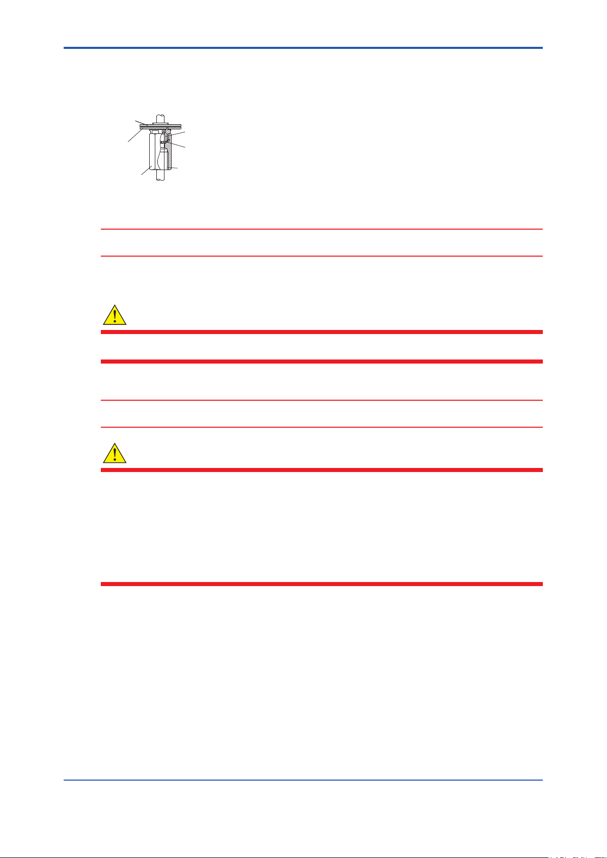
2.2.2 Installation cable gland
Follow the next procedure to install the supplied cable gland. (Figure 3)
The supplied cable glands are for cables with an outside diameter of 6 to 12 mm (0.24 to 0.47 inches).
(1) Push the plate along with the metal plate to help indicate the position.
(2) Conrm that the cable gland has gasket and washer attached. Screw lightly the three cable
glands from the bottom of the case while keeping the setscrews settled properly.
(3) Tighten the cable glands to the torque of 2 N•m.
Unused cable entry holes must be sealed with cable glands including the supplied rubber plugs.
CAUTION
● Be careful not to be injured by the sharp hole edges on the housing.
● Tighten the cable glands to the torque of 2 N•m. (rating IP66 or higher)
Power cable inlet
Plate
Washer
Oscillator cable inlet
(unused)
Plate for positioning
Gasket
Cable gland
Figure 3 Cable glands
Rubber plug
IM 19C01B05-01EN 1st Edition : Feb. 18, 2021-00
<PG400 Pulse Generator for Clean Unit>
l Conduit adapter
When protecting the cable with a conduit, use an adapter. (option codes: /CB, /CD, /CF)
Apply the supplied cable gland for adapter (white) to the holes which conduit adapters connect to
instead of using supplied-accessory cable gland (dark gray). Caps of cable glands are not used.
Plate
Case
Adapter
Figure 4 Conduit adapter (option)
Packing
Tab
G1/2 female thread (/CB)
1/2 NPT female thread (/CD)
M20x1.5 (/CF)
CAUTION
When using a cable conduit, use a exible conduit to avoid stress on the conduit adapter.
The excessive stress on the conduit adapter may damage the housing.
2.2.3 Wiring power supply
WARNING
13
Use wiring cables with heat resistance above 75°C.
For power supply, wire cables with a ammability rating of UL 2556 VW-1 or equivalent.
CAUTION
Turn o power supply to PG400 before wiring. Power rating must comply with PG400
specication. Power voltage must match with the one indicated on the name plate.
WARNING
● You must install external power supply switch or circuit breaker for power supply.
● The external power supply switch or a circuit breaker must comply with a current rating of
5A, IEC60947-1 or IEC60947-3.
● Yokogawa recommend installing the external power supply switch, circuit breaker and
PG400 all in the same location.
● Install the external power supply switch or circuit breaker to the place where operators
access easily. To alert users, put a label on the external power switch.
● Wire cables of power supply or contact output securely with cable rack, conduit and vinyl
band. Unplugged cables are dangerous and may cause an electric shock.
Some regions where the instrument is used may require the installation of an external circuit
breaker.
When TB810D or TB820 supplies power, no installation of an external circuit breaker is needed.
To prepare for wiring cables, open the front cover and remove the protect cover so that you can
access terminals easily.
The size of power supply cable is 2.0 mm2 (14 AWG) or larger. Use the crimp terminals of 7.2 mm
or less width. The terminals use M4 screw.
l Power supply
Connect cables to the power terminals L, N. See Figure 1. Use crimp terminals.(ring or fork type)
IM 19C01B05-01EN 1st Edition : Feb. 18, 2021-00

<PG400 Pulse Generator for Clean Unit>
l Grounding
WARNING
Use the protective earth conductors whose minimum size of the cross-sectional area is 0.75 mm2.
For CSA compliance (Type: -AD), use ones with cross-section area of 0.75 mm2 to 2.1 mm2.
CAUTION
Connect PG400 to ground (Class D ground: 100 ohm or less) for interference avoidance and
safety reasons.
Use ground cables with larger cross - sectional area. Connect the ground cable to the internal/
external grounding terminal. (Figure 5) Use ring terminals for wiring terminals.
14
(M4 screw) (M4 screw)
Figure5 External(rear)grounding,Internalgrounding
2.2.4 Wiring to output terminal
The type of oscillator cables to connect to output terminals or shield terminals varies depending
on the instrument to connect.
l -PU (Connect to PH8HS, PH8HF)
Wire the oscillator cable to terminal U1, U2, and S. Oscillator cables are supplied to PH8HS or
PH8HF with ultrasonic cleaning specied. The terminal U3 is not used.
l -TU (Connect to TB810D, TB820D/TB700G, TB750G)
When connecting to TB810D or TB820D, wire the oscillator cable to terminal U1, U2 and S. You
need to purchase the oscillator cable separately.
When connecting to TB700G or TB750G, wire the oscillator cable to terminal U1, U2, U3 and
S.You can continue to use the existing oscillator cables.
To connect to TB810D- with -ST, or for its replacement, use the cable as shown in note *4 on
“Model and Sux Codes” table.
3. Operation
After every wiring completes and the cover is installed, turn on the power and conrm the green
POWER LED is lit. To start the cleaning, turn on the output switch inside the instrument and
conrm the red OUTPUT LED is lit. Make an adjustment of ultrasonic power then shut the front
cover.
WARNING
To avoid electric shock, do not insert thin or exible wires or the like from the opening of the
instrument.
IM 19C01B05-01EN 1st Edition : Feb. 18, 2021-00

<PG400 Pulse Generator for Clean Unit>
CAUTION
● When the oscillator does not contact uid, turn o the output switch to avoid damages to
instrument.
● Tighten the four front cover screws to the torque of 1.5 to 1.6 N·m.
n Adjusting ultrasonic power
In ultrasonic cleaning, cavitation caused by the application of ultrasonic waves contributes to the
cleaning eect. The more cavities are produced, the more the cleaning eect is enhanced.
In turbidity measurement using an optical system or pH measurement, however, measured
values are more largely inuenced with increase in the number of cavities produced.
PG400 can adjust the ultrasonic power so that the inuence on measurements is controlled to
within an allowable range and provide the most ecient cleaning.
Adjusting the ultrasonic power is recommended, when using for the rst-time, replacing the
ultrasonic oscillator, or changing the process ow rate.
l Adjusting Procedure
Adjust the ultrasonic power by turning the volume adjuster. Adjust it so that the measurement
dierence of turbidity detector or pH sensor can fall within an allowable range between when the
ultrasonic cleeaning is on and o.
(1) Turn OFF the output switch of PG400. Then, feed a sample water into the turbidity detector
or pH sensor at the same ow rate as in a steady-state operation. Actuate the turbidimeter
or pH analyzer.
Note: Even if the ultrasonic power is the same, the inuence of ultrasonic waves on measured values varies depending
on the properties (velocity of ow and amount of suspended solids) of uid in the sample cell.
(2) Keep the output switch turned OFF. Wait until the turbidity or pH measurement becomes
stable then record the measurement value.
(3) Turn ON the output switch of PG400. Wait until the turbidity or pH measurement becomes
stable then record the measurement value.
(4) Compare the result from (2) and (3). If the dierence between the two measurement
is within an allowable range, the adjustment is complete. If not, you need to adjust the
ultrasonic power. Insert a athead screwdriver into the slot of the volume adjuster and turn it
counterclockwise to reduce the ultrasonic power. (Figure.3.1) Then, return to (3).
Note:In case the power seems to have lowered excessively, turn it clockwise to increase the power.
Then, return to (3).
15
4. Maintenance
The PG400 requires very little periodic maintenance, except to make sure the front window is
kept clean in order to permit a clear view of the LED.
If the window becomes soiled, clean it using a soft damp cloth or soft tissue. To deal with more
stubborn stains, a neutral detergent may be used.
When you must open the front cover and/or remove cable glands, make sure that the seals
are clean and correctly tted when the unit is re-assembled in order to maintain the housing’s
weatherproof integrity against water and water vapor.
CAUTION
Never use harsh chemicals or solvents. If the window does become heavily stained or scratched,
parts replacement might be required.
Contact Yokogawa service when replacing the front cover. Part numbers are
coating), or K8008DF (Code of Housing “-D”, High anti-corrosion coating).
K8008DC (Code of Housing “-B”, Urethane
IM 19C01B05-01EN 1st Edition : Feb. 18, 2021-00

<PG400 Pulse Generator for Clean Unit>
Check sometimes whether POWER LED, OUTPUT LED is lit. If they are not lit on, refer to the
following procedure.
● POWERLEDiso.
PG400 is protected by fuse which provides overcurrent protection of inner circuit.
POWER LED is o because the fuse may be blown out. To replace the fuse with a new
one(A1109EF), shut o the power supply rst then remove the protect cover. If the POWER
LED stays o even after the fuse is replaced, contact Yokogawa service center. For
replacement, use the fuse with a rating specied on page 7 the table “Option parts”.
WARNING
Fuse replacement should be performed only by a qualied service personnel.
● OUTPUTLEDiso.
If OUTPUT LED is o, even when POWER LED is lit on and the output switch is on, contact
Yokogawa service.
n Nocleaningeectbyultrasoniccleaning
Ultrasonic cleaning is considered to be working eectively, when no visible contamination is
found on the surface of glass electrode/junction of pH sensors, or the window of ultrasonic
oscillator of turbidity detectors. However, if you found no or little eect even after the cleaning-
power adjustment, the possible reasons would be as follows.
● Ultrasonicoscillatorerror
Check whether there is a hole made by a surface corrosion of the oscillator. If there is the
corrosion and uid enters the instrument, other parts may need to be replaced.
● Oscillatorcableerror
Shut o the power supply then check whether there is wire disconnection or short circuit.
16
NOTE
Adhesive substances in sample may aect the junction of the ultrasonic oscillator. The
contamination of the wetted surface, especially on the surface of the vibrating part should be
removed. The contamination may impair the cleaning eect. If the sample contains adhesive
contaminants, keep the surface from the xation of contaminations when the operation is
paused. Refer to each detector’s user’s manual for cleaning those contaminants including
chemicals or substances which ultrasonic cleaning may not be eective to.
Revision Record
Feb. 2021/1st Edition
Newly published
Yokogawa Electric Corporation
2-9-32 Nakacho, Musashino-shi, Tokyo 180-8750, JAPAN
http://www.yokogawa.com/
IM 19C01B05-01EN 1st Edition : Feb. 18, 2021-00
 Loading...