

Page 1
Instruction
Manual
This User's Manual contains useful information about the functions and operating procedures as well as the handling precautions for the
MT10 mini manometer. To ensure correct use of the MT10 mini manometer, please read this manual thoroughly before use.
● The contents of this manual are subject to change without prior notice.
● All rights reserved. No part of this manual may be reproduced or transmitted in any form or by any means without the written
permission of Yokogawa.
● Every effort has been made in the preparation of this document to ensure the accuracy of its contents. However, should you have any
questions or find any errors, please contact your nearest Yokogawa representative as listed on the back cover of this manual.
Trademarks
IBM PC/AT is a registered trademark of International Business Machines Corporation.
Disk No. BA02
5th Edition : April 2010 (YK)
All Rights Reserved, Copyright © 1997, Yokogawa Electric Corporation
MT10
Mini Manometer
IM 265301-01E
5th Edition
When Product Is Delivered to You
Please check the contents of the package. If the wrong instrument or accessories have been delivered, if some accessories are
missing, or if they appear abnormal, contact the dealer from whom you purchased them. At that time, please give the dealer the
model name, suffix code, and serial number found on the name plate attached at the rear of the product.
1. Safety Precautions
Be sure to follow the instructions and requirements on safety described in this manual when handling the product. If this
instrument is used in a manner not specified in this manual, the protection provided by this instrument may be impaired.
Yokogawa Electric Corporation assumes no liability for the customer's failure to comply with those instructions and require-
ments.
WARNING Describes precautions that should be observed to prevent the danger of serious injury or death to the
CAUTION Describes precautions that should be observed to prevent the danger of minor or moderate injury to the
<Note> Provides information that is important for proper operation of the instrument.
The following symbols are used on this instrument.
WARNING 1. Precautions Against Explosion
CAUTION 1. Do not apply a pressure exceeding the specified maximum allowable input. It may damage the
user.
user, or the damage to the property.
To avoid injury, death of personnel or damage to the instrument, the operator must refer to an explanation in the
Instruction Manual.
Direct current
Do not operate the instrument in the presence of flammable or explosive gases or vapors since this
instrument is not explosion-proof. Operation of the instrument in such an environment constitutes
a safety hazard.
2. High-pressure Gases
• Use a measuring tube and pressure connector rigid enough to withstand the pressure being
measured.
• Check the measuring tube, pressure connector and their joints to ensure that there is no leaking
of the fluid being measured or separation in the joints. Any such leakage or separation can be
hazardous to personnel or equipment near the instrument because of the pressure. Exercise due
care since the greater the pressure is, the greater the risk will be.
3. Connection of AC Power
Confirm that the POWER switch is off before plugging in the power cord.
4. Protective Grounding for AC Power Supply
To prevent electrical shock, use only the power cord supplied by YOKOGAWA. Connect the
power cord to a grounded AC outlet. Use a power cord whose rated voltage complies to the rated
voltage of the instrument. Do not use an extension cord that does not have protective grounding.
5. Do not use any AC power supply other than the power supply kit(model 366969) manufactured by
YOKOGAWA.
instrument. (For the maximum allowable input, see Chapter 7, "Specifications.")
2. Avoid measuring the pressure of a corrosive gas, hot fluid (50 °C or higher), liquid, or mixture of a
gas and liquid.
3. Internal condensation may occur if the instrument is moved to another place where both ambient
temperature and humidity are higher, or if the room temperature changes rapidly. In such cases
acclimatize the instrument to the new environment for at least one hour before starting operation.
4. If exposed to direct sunlight, the instrument heats up to temperatures higher than the surrounding
air. Do not use the instrument in a location exposed to direct sunlight.
5. When tightening the connector to the input port, do not place only one spanner on the connector.
It may damage the internal piping of the instrument. Use two spanners: one to hold onto the
flattened portion of the input port and another to hold the connector. Then, tighten the connector to
the input port.
6. Remove the batteries when they have run out or when not using the instrument for a long time.
Leaving them installed may result in a failure due to leakage of battery acid.
7. Keep the instrument away from volatile chemicals and do not allow a rubber or vinyl product to
come into contact with the case or operation panel. It may result in discoloration.
8. Do not remove the cover from the instrument. When the instrument needs internal inspection or
adjustment, contact your dealer or the nearest Yokogawa representative as listed on the back
cover of this manual.
9. If you notice smoke or unusual odors coming from the instrument, immediately stop using it. Contact your dealer or the nearest Yokogawa representative.
3. Before Starting Measurement
■ Ambient Temperature and Humidity (See CAUTION 3 and 4)
● The instrument must be used only where the following conditions are met:
• Ambient temperature: 5 to 40 °C•Ambient humidity: 20 to 80 % RH No condensation is allowed.
● Do NOT use the instrument in the following places:
• Near heat sources • Where an excessive amount of soot, steam, or dust is present
• Where corrosive gases may be present • Near strong magnetic field sources
• Near high-voltage equipment or power lines
■ Power (See WARNINGS 3 and 4)
This instrument can be driven by either AA-size batteries or AC power through the dedicated AC adapter. When the batteries
have nearly run out, the battery alarm LED lights up.
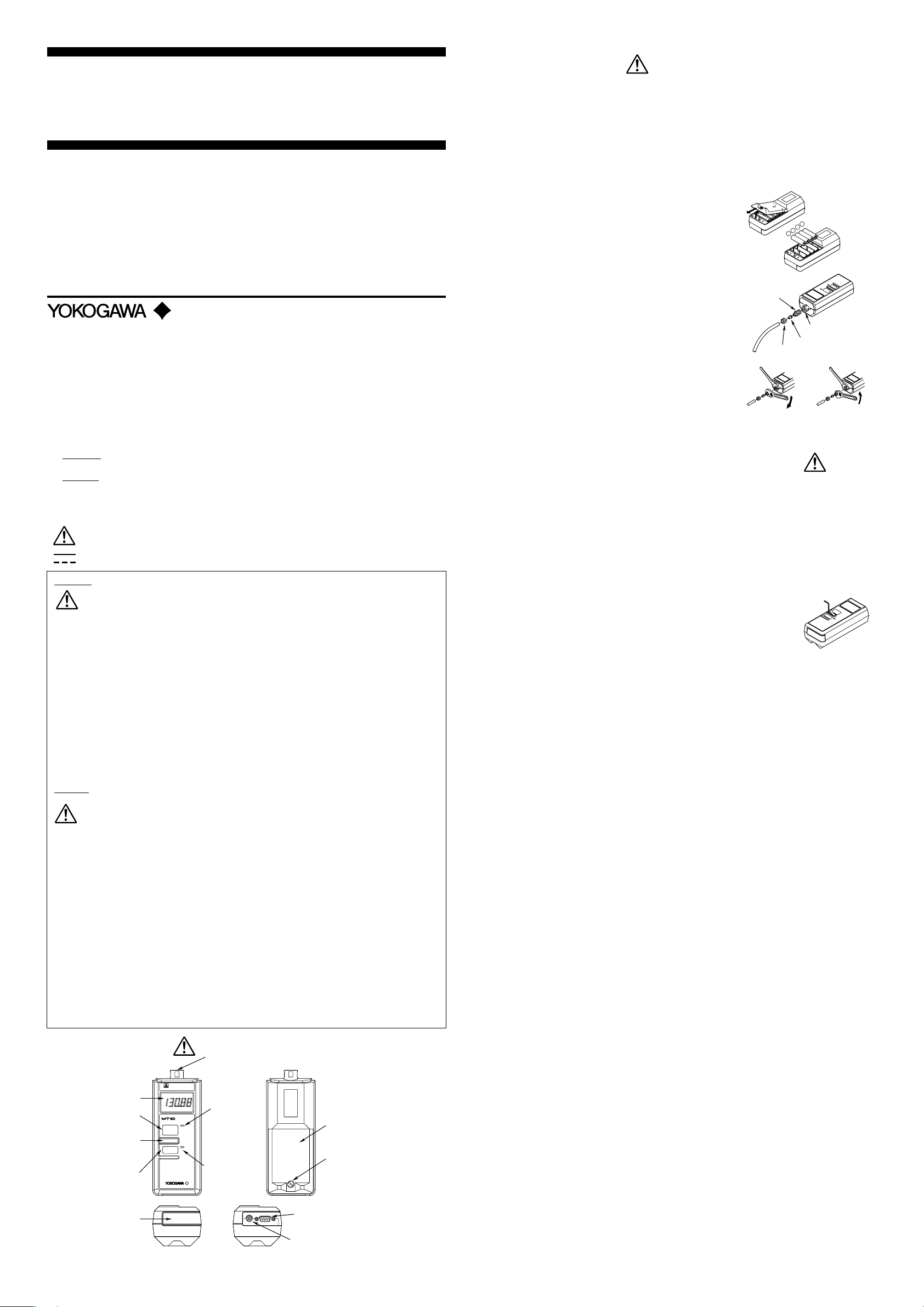
● Installing the batteries
(1) Turn off the power.
(2) Use a coin or a tool with a screwdriver-like tip to loosen the screw
holding battery cover and detach the cover.
(3) Replace all four batteries with new ones. Note the polarity of each
–
+
–
+
battery when installing the new ones. Make sure that they are all in-
stalled correctly, as shown on the holder.
(4) Put the cover back in its original position and tighten the screw.
● Connecting the AC adapter (See CAUTION 10)
(1) Turn off the power.
Connector
(2) Plug the AC adapter cable into the connector of the instrument.
(3) Plug the power cord into the AC adapter and then plug the other end of
the cord into an AC outlet.
■ Input Connection Procedure (See CAUTION 5)
This item takes the optional connector assembly (B9310RR) as an example
in explaining how to connect a pressure-leading tube to the input port.
Nut
Fixed Fixed
Input port
(Rc1/4 or NPT1/4)
Sleeve
(1) Wind duct tape tightly around the connector to prevent leakage.
(2) Tighten the connector firmly to the input port (Rc1/4 female) to pre-
vent leakage.
(3) Insert the tip of the pressure leading tube through the opening of the
nut and then insert the sleeve at the tip of the tube. Firmly fix the
For screwing
For loosening
sleeve to the tube with the nut. Finally screw the nut into the connec-
tor.
4. Measuring the Pressure (See WARNINGS 1 and 2 and CAUTIONS 1 and 2)
■ Power On/Off and Behavior at Power-on
Pressing the POWER key on the front panel turns on the power. Pressing it again turns the power off. Immediately after the
power is turned on, all display elements appear on the LCD panel and the instrument is then ready for measurement.
<Note> Sometimes the display may enter the hold mode at power-on. If this occurs, press the HOLD key to cancel the mode
before you begin operating the instrument.
■ Zero Calibration (Zero CAL)
Compensation for effects resulting from variations in temperature and/or the installation environment in order to carry out
precision pressure measurements is called "zero calibration" (zero CAL). This feature may not be necessary in regular mea-
surements (measurements in a horizontal position). It is advisable, however, that you use the zero-CAL function to measure
pressure with better accuracy. Also activate the zero-CAL function, once in a while, if your operating environment is likely to
vary during continuous measurement.
● Implementing Zero Calibration Manually
1) Set the input to open atmosphere.
2) Lift the left end of the zero-CAL cover.
3) Using the supplied Allen wrench, adjust the zero-CAL control so the display reads 0.
The reading increases as you turn the control clockwise, and decreases as you turn it counterclockwise.
● Implementing Zero Calibration Via Communication
1) Set the input to open atmosphere.
2) Send a zero-calibration command from a personal computer (see "Programming" in Chapter 5, "Communication Func-
tions," for details on commands).
■ Holding a Measurement
Use the HOLD key to hold an indicated measurement. The indication will not be updated until the HOLD mode is released.
Pressing the HOLD key stops updating an indicated measurement and the LED beside the HOLD key lights up. Pressing the
HOLD key again restarts updating and the LED turns off.
■ Behavior Upon Error
An error code (Er.xx) corresponding to the cause of an error is displayed on the LCD panel. (For error codes, see "Trouble-
shooting" in Chapter 6, "Maintenance and Calibration.")
5. Communication Function
■ Communication Data
Transmission: measured data
reception: zero calibration
■ RS-232-C Interface Specifications
Electric characteristic : Conforms to EIA RS-232-C
Connection : Point-to-point
Communications : Half-duplex
Synchronization : Start-stop system (asynchronous)
Baud rate : 1200 bps
Start bit : 1 (fixed)
Data length : 8 bits
Parity : No (off)
Stop bit : 1 bit
Connector : DELC-J9PAF-13L6 from JAE (or the equivalent)
Hardware and software handshaking: None
Receive buffer size : 37 bytes
2. Parts and Their Functions
Display
HOLD (measurement
holding) key
Zero-adjuster screw
(use the hexagon
wrench included
in the accessories)
POWER switch
Rubber cover
(one end attached
to the case)
When rubber cover is closed When rubber cover is open
INPUT
HOLD
POWER
RANGE 130kPa
500kPa Max
kPa
MINI MANOMETER
BATTERY
ALARM
Pressure input port
HOLD status
LED
Battery alarm
LED
Battery cover
Battery cover screw
RS-232-C interface
connector
Connector for AC adapter
Page 2
■ Connecting the RS-232-C Interface Cable
When connecting this instrument to a personal computer, see the following descriptions and make sure that the setups (data
transmission speed, data format, etc.) between the instrument and computer match. Also, make sure that the correct interface
cable meeting the specifications for this instrument is used.
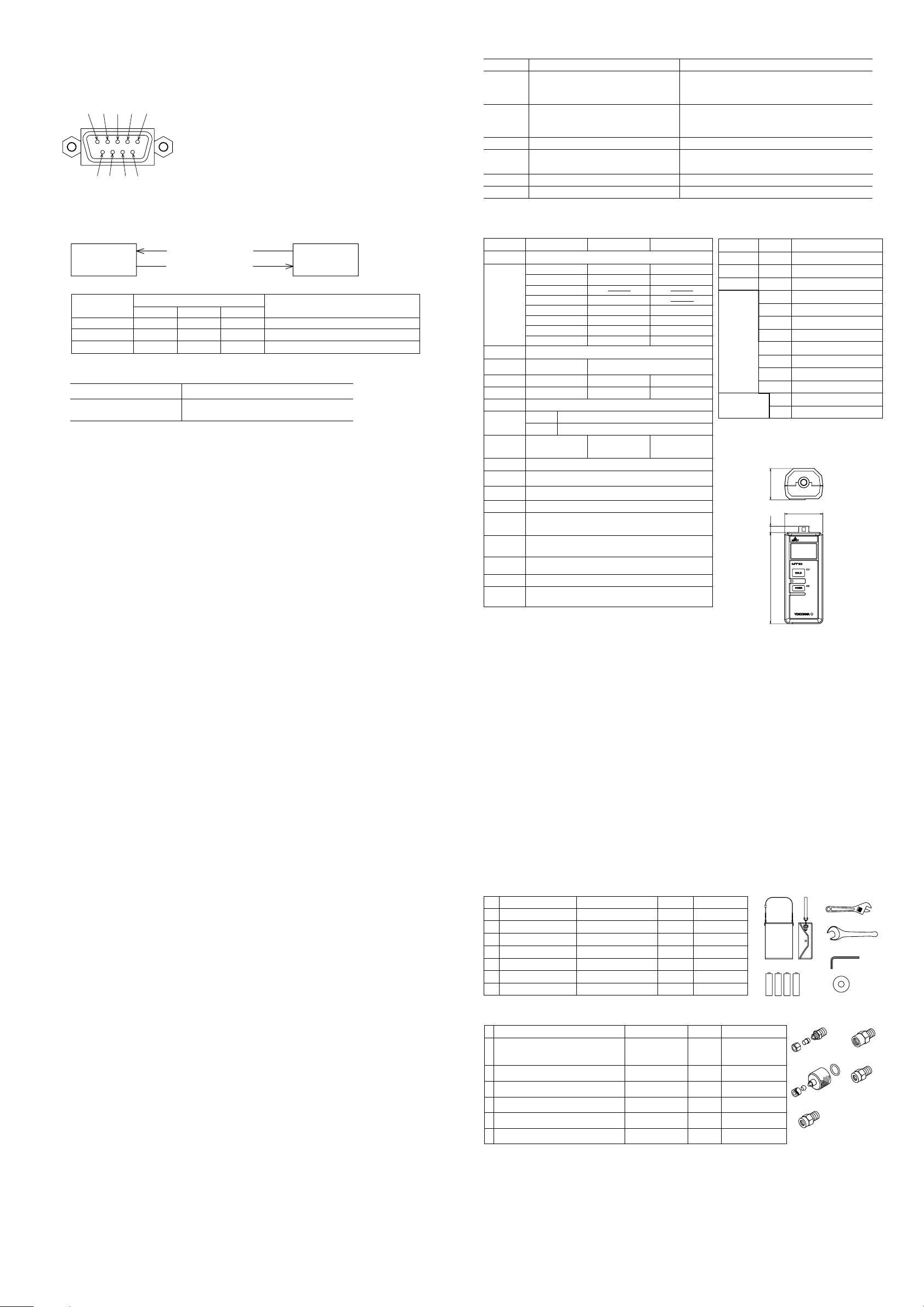
● Connector Pin Assignment
2 1 3 4 5
6 7 8 9
2 BB(RXD; Received Data) : Data received from personal computer
3 BA(TXD; Transmitted Data) : Data transmitted to personal computer
5 AB(GND; Signal Ground) : Ground for signals
Pins 1, 4, and 6 through 9 are not used.
Signal direction : Input
Signal direction : Output
RS-232-C Connector (DELC-J9PAF-13L6)
(D-Sub 9-pin male connector on the instrument)
● Directions of Signals
The figure below shows the directions of the signals used by the RS-232-C interface.
Personal
computer
SD (transmitted data)
RD (received data)
3
MT10
2
● Table of RS-232-C Standard Signals and Their CCITT and JIS Abbreviations
Pin No.
(9-pin connector)
5
3
2
RS-232-C CCITT JIS
AB(GND)
BA(TXD)
BB(RXD)
Abbreviation
102
103
104
SG
Signal ground
SD
Transmitted data (output)
RD
Received data (input)
Signal
■ Programming
● Commands Corresponding to Functions
Function Command Data
Zero calibration
Measured-data transmission
● Format of Output When Receiving Measured-data Transmission Command
Request to MT10 : Computer converts command data to characters and sends them.
Reply from MT10 : Computer reads measured values sent.
******** (8 bytes) (8 bytes) (8 bytes) *
Name Data Aux. data
Name : INPUT (The space is filled with blanks.)
Data : Measurement (The space is filled with blanks.)
Aux. data : Pressure unit (The space is filled with blanks.)
Asterisk (*): Each denotes a one-byte character (which is meaningless to the user-to be ignored).
<Note> The carriage return (CR) or linefeed (LF) code is not output.
● Sample Programs (Quick Basic Version 4.5)
Computer : IBM PC/AT and compatible system with serial port
1. Execute Zero Calibration
1000 ‘************************************
1010 ‘ EXECUTE ZERO CALIBRATION
1020 ‘
1030 ‘ SAVE “MT10ZCL2.BAS”,A
1040 ‘************************************
1050 INPUT “EXECUTE ZERO CALIBRATION. (Y/N) >> “,Q$
1060 IF Q$=”N” OR Q$=”n” THEN 1160
1070 IF Q$<>”Y” AND Q$<>”y” THEN 1050
1080 ‘
1090 TX$=CHR$(0)+CHR$(0)+CHR$(18)+CHR$(12)+CHR$(64)+CHR$(10)+CHR$(10)+CHR$(0)
1100 TX$=TX$+CHR$(32)+CHR$(32)+CHR$(32)+CHR$(32)+CHR$(32)+CHR$(48)+CHR$(46)+CHR$(48)+CHR$(160)
1110 ‘
1120 OPEN “COM1:1200,N,8,1,DS0,CS0,LF” AS #1
1130 PRINT #1,TX$;
1140 CLOSE #1
1150 PRINT “COMPLETED.”
1160 END
2. Read Measured Data 100 Times
1000 ‘************************************
1010 ‘ READ MEASURED DATA 100 TIMES
1020 ‘
1030 ‘ SAVE “MT10MES2.BAS”,A
1040 ‘************************************
1050 INPUT “READ MEASURED DATA 100 TIMES. (Y/N) >> “,Q$
1060 IF Q$=”N” OR Q$=”n” THEN 1200
1070 IF Q$<>”Y” AND Q$<>”y” THEN 1050
1080 ‘
1090 TX$=CHR$(0)+CHR$(0)+CHR$(18)+CHR$(4)+CHR$(128)+CHR$(1)+CHR$(40)+CHR$(0)+CHR$(191)
1100 ‘
1110 OPEN “COM1:1200,N,8,1,DS0,CS0,LF” AS #1
1120 FOR J=1 TO 100
1130 PRINT #1,TX$;
1140 A$=INPUT$(33,#1)
1150 B$=MID$(A$,9,24)
1160 PRINT B$
1170 FOR I=1 TO 10000 : NEXT I
1180 NEXT J
1190 CLOSE #1
1200 END
0,0,18,12,64,10,10,0,32,32,32,32,32,48,46,48,160
0,0,18,4,128,1,40,0,191
6. Maintenance and Calibration (See CAUTIONS 6 through 9)
■ Storage Conditions
● The following conditions must be met when storing this instrument:
Ambient temperature: -20 to 70 °C; ambient humidity: 5 to 95 % RH or less
● Avoid storing this instrument in any of the following locations:
Damp places; in direct sunlight; near heat sources; where the level of mechanical vibration is high; where an excessive
amount of dirt, dust or salinity is present; where corrosive gases may be present
■ Cleaning the Instrument
Cleaning the instrument with a volatile solvent such as a thinner or benzene may cause discoloration. Use a damp cloth
moistened with water or alcohol to wipe the instrument carefully.
■ Calibration
The calibration guarantee period of this instrument is one year. Periodic calibration is recommended for correct use of the
instrument. For calibration, please contact your nearest Yokogawa representative, listed on the back cover of this manual.
■ Blank Display at Power-on (When Operating on Batteries or AC Power Supply)
Replace all four batteries with new ones at the same time, and then switch the manometer on.
If the problem still persists, contact your nearest Yokogawa representative, listed on the back cover of this manual.
■ Troubleshooting
Error Code Cause of Error Countermeasure
Needs repair. Immediately turn off the power and
Er.01 Sensor failure
contact your nearest Yokogawa representative, listed on
the back cover of this manual.
Needs repair. Immediately turn off the power and
Er.02 Circuit failure
contact your nearest Yokogawa representative, listed on
the back cover of this manual.
Er.03 Input exceeds measuring range Check the input value.
Er.07
Input exceeds measurment display range
Turning the wrench clockwise, adjust the display reads
0.
Er.08 Measured value exceeds high/low limits Check the input value.
Er.12 Zero point shifting widely Readjust the zero point.
*If the other error codes are displayed, please contact your YOKOGAWA sales representative.
7. Specifications
■ General Specifications ■ Model Specification
Model
Pressure Type Gauge pressure
Measuring
Range (with
guranteed
accuracy)
Measurement
Display Range
Accuracy*
Resolution
Maximum
Allowable Input
Internal Capacity
Temperature
Coefficient
Effect of
Mounting
Direction
Gas Leakage 10-5 cm3/s max
Measurement
Fluid
Measurement
Fluid Temperature
Pressure Sensor
Pressure
Sensing
Element
Pressure
Display
*2
Unit
Calibration
Interval
Input Connection
Material of
measurement
section
*1: Reference conditions: positioned horizontally, temperature 23°±3°C,
and immediately after zero calibration.
265302 265303 265304
0 to 130 kPa 0 to 700 kPa 0 to 3000 kPa
0 to 1.3256 kgf/cm
0 to 13256 mmH2O
0 to 975.1mmHg 0 to 5250 mmHg
0 to 521.9 inH
0 to 38.39 inHg 0 to 206.7 inHg 0 to 885.9 inHg
0 to 18.86 psi 0 to 101.5 psi 0 to 435.1 psi
0 to 1300 mbar 0 to 7000 mbar 0 to 30 bar
1
±(0.04% of rdg +
0.03% of FS)
0.01kPa
500kPa 1000kPa 4500kPa
Zero drift ±0.02% of FS/10°C
Span drift ±0.02% of FS/10°C
±0.1% of FS ±0.02% of FS ±0.01% of FS
Gases only (non-flammable, non-explosive, non-toxic, and non-corrosive gases)
kPa, kgf/cm
Japanese Industrial Standard SUS316 stainless steel; Hastelloy C276
2
0 to 7.138 kgf/cm20 to 30.59 kgf/cm
2
O0 to 2810 inH2O0 to 12044 inH2O
-2.5 to 110% of measuring range
±0.1% of FS
0.1kPa 1kPa
Approx. 2 cm
Silicon resonant sensor
2
, mmH2O, mmHg, inH2O, inHg, psi or mbar
(one specified upon shipment)
Rc1/4 female or NPT1/4 female
3
5° to 50°C
Diaphragm
1 year
■ Complying Standard
General Safety EN61010-1: 1993/A2: 1995
SEMKO Certified
EMC: EN55011(1991), EN55022(1994), EN50082-1(1992), EN61000-4-2(1995)
SEMKO Verified
The influence under the immunity environment is +/-30% of FS.
■ Common Specifications
Power Supply: AA-size batteries; four 1.5-V primary batteries or four 1. 2-V secondary batteries (will last for approximately 100 continuous
hours if alkaline batteries are used), AC adapter (100-120/220-240 V AC, 50/60 Hz, with 15 V/1.33 A output); optional
Communication: RS-232-C
Transmission: half-duplex "brain" protocol
Baud rate: 1200 bps
Display: 4.5 digits, LCD
Display Update Interval: approximately 0.5 second
Response: approximately 4 seconds (before the reading falls within the given accuracy)
Other Functions: Hold function that retains the on-display pressure reading, Zero-point adjustment
Warm-up Time: one minute maximum
Insulation Resistance: 500 V DC, 20 MΩ MIN. (between the AC power line and case), when the dedicated AC adapter is used
Withstanding Voltage: 1500 V AC/one minute (between the AC power line and case), when the dedicated AC adapter is used
Operating Temperature/Humidity Range: 5 to 40 °C, 20 to 80 % RH (non-condensing)
Storage Temperature/Humidity Range: -25 to 70 °C, 5 to 95 % RH
External Dimensions/Weight: approximately 72 (W) x 174 (H) x 60 (D)(mm), excluding the input connection/approximately 700 g
■ Standard Accessories
Accessory Part or Model No.
1 Carrying case B9926CZ
2 Alkaline AA-size A1070EB*
3 Monkey spanner B9926CX
4 Single-ended wrench B9926CW
5 Hexagon wrench B9926CY
6 Duct tape X9910DG
- User's manual IM 265301-01E
Quantity
1
4
1
1
1
1
1
Specification(s)
1.5 V DC
150 mm
H19
H2.5
-
This manual
*: Part no. A1070EB specifies only one AA battery.
■ Optional Accessories
Accessory
AC power supply kit
-
Connector assembly (for a vinyl tube with inner
7
diameter of 4 mm and outer diameter of 6 mm)
Simple connector assembly (for a vinyl tube with
8
inner diameter of 4 mm and outer diameter of 6 mm)
Adapting connector (JIS, R1/4-to-Rc1/8)
9
Adapting connector (ANSI, R1/4-to-1/4NPT
10
female thread)
Adapting connector (ANSI, R1/4-to-1/8NPT
11
female thread)
Part or Model No.
366969
B9310RR
B9310ZH
G9612BG
G9612BJ
G9612BW
Quantity
Model
Suffix Code
265302
265302
· · · · · · · · · ·
265303
265304
2
· · · · · · · · · ·
· · · · · · · · · ·
-U1 kPa
-U2 kgf/cm
-U3 mmH2O
-U4 mmHg
-U5
-U6
-U7
-U8
-P1 Rc1/4 female
-P2 NPT1/4 female
2
Pressure
Display
Unit *
Input Connection
*2: The specification U3 is not available for Model 265303.
For Model 265304, the specifications U3 and U4 are
not available.
*3: For Model 265304 only
Specification(s)
Mini manometer (130 kPa)
Mini manometer (700 kPa)
Mini manometer (3000 kPa)
2
2
O
inH
inHg
psi
mbar (bar *3)
■ External Dimensions
6012174
72
1
3
4
5
2
6
Specification Code
-D: UL/CSA Standard
-F: VDE Standard
(1)
-R: SAA Standard
-Q: BS Standard
1
1
1
1
1
7
8
9
10
11
 Loading...