

Page 1

GS200
DC Voltage/Current Source
IM GS210-01EN
3rd Edition
Page 2

Product Registration
Thank you for purchasing YOKOGAWA products.
YOKOGAWA provides registered users with a variety of information and
services.
Please allow us to serve you best by completing the product registration
form accessible from our homepage.
http://tmi.yokogawa.com/
PIM 103-03E
Page 3

Notes
Trademarks
Thank you for purchasing the GS200 DC voltage/current source.
This user’s manual explains the features, operating procedures, and handling
precautions of the GS200. To ensure correct use, please read this manual thoroughly
before beginning operation. Keep this manual in a safe place for quick reference in the
event a question arises.
• The contents of this manual are subject to change without prior notice as a result
of continuing improvements to the instrument’s performance and functionality. The
figures given in this manual may differ from those that actually appear on your screen.
•
Every effort has been made in the preparation of this manual t
o ensure the accuracy
of its contents. However, should you have any questions or find any errors, please
contact your nearest YOKOGAWA dealer.
• Copying or reproducing all or any part of the contents of this manual without
YOKOGA
• The TCP/IP
WA’s permission is strictly prohibited.
software of this product and the document concerning the TCP/IP
software have been developed/created by YOKOGAWA based on the BSD Networking
Software, Release 1 that has been licensed from University of California.
• Microsoft, Internet Explorer, MS-DOS, Windows, and Windows XP are either
registered trademarks or trademarks of Microsoft Corporation in the United States
and/or other countries.
•
Adobe and Acrobat are trademarks of
• In this manual, the TM and
® symbols do not accompany their respective registered
Adobe Systems Incorporated.
trademark or trademark names.
• Other company and product names are registered trademarks or trademarks of their
respective holders.
Revisions
• 1st Edition : December 2009
• 2nd Edition: July 2012
• 3rd Edition: September 2013
3rd Edition: September 2013 (YMI)
All Rights Reserved, Copyright ©2009, Yokogawa Electric Corporation
All Rights Reserved, Copyright ©2012, Yokogawa Meters & Instruments Corporation
IM GS210-01EN
i
Page 4
Checking the Contents of the Package
MODEL
SUFFIX
Made in Japan
NO
MODEL
SUFFIX
Made in Japan
NO
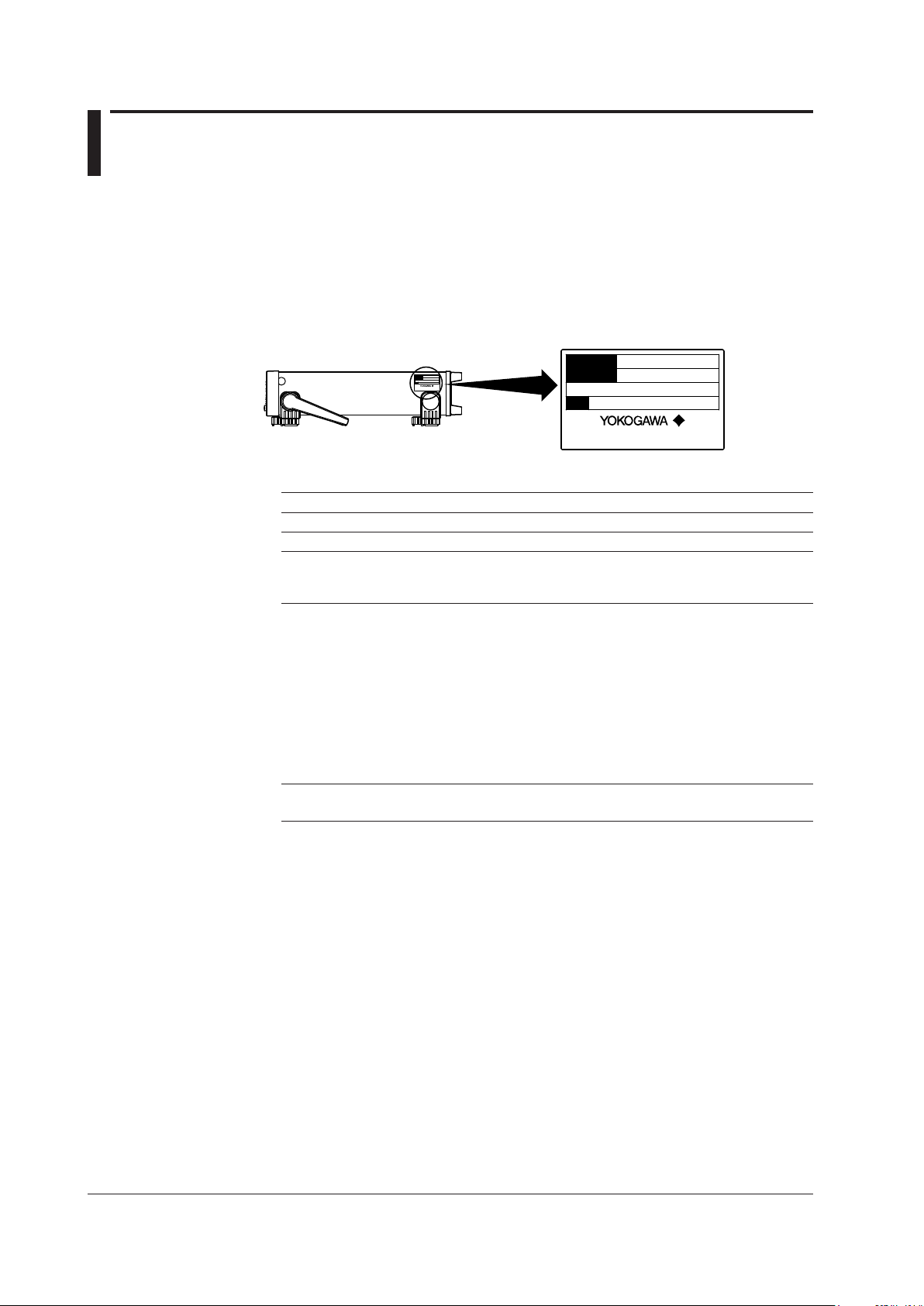
After receiving the product and opening the package, check the items described below.
If the wrong items have been delivered, if items are missing, or if there is a problem with
the appearance of the items, contact your nearest YOKOGAWA dealer.
GS200
Check that the model name and suffix code given on the name plate on the side panel
are the same as those on your order.
MODEL and SUFFIX Codes
Model Suffix Code Description
GS210 DC voltage/current source (front panel output terminals)
GS211 DC voltage/current source (rear panel output terminals)
Supply voltage -1 100 VAC, 50/60 Hz
-4 120 VAC, 50/60 Hz
-7 230 VAC, 50/60 Hz
Power cord
[Maximum rated voltage: 125 V; Maximum rated current: 7A]
-F VDE Standard Power Cord (Part No.: A1009WD)
[Maximum rated voltage: 250 V; Maximum rated current: 10 A]
-Q BS Standard Power Cord (Part No.: A1054WD)
[Maximum rated voltage: 250 V; Maximum rated current: 10 A]
-R AS Standard Power Cord (Part No.: A1024WD)
[Maximum rated voltage: 250 V; Maximum rated current: 10 A]
-H GB Standard Power Cord (Part No.: A1064WD)
[Maximum rated voltage: 250 V; Maximum rated current: 10 A]
Options /MON Voltage and current monitoring
/C10 Ethernet interface
1
-D UL/CSA Standard Power Cord (Part No.: A1006WD)
1 Make sure that the attached power cord meets the designated standards of the country and
area that you are using it in.
NO. (Instrument Number)
When contacting the dealer from which you purchased the instrument, please tell them
the instrument number.
ii
IM GS210-01EN
Page 5
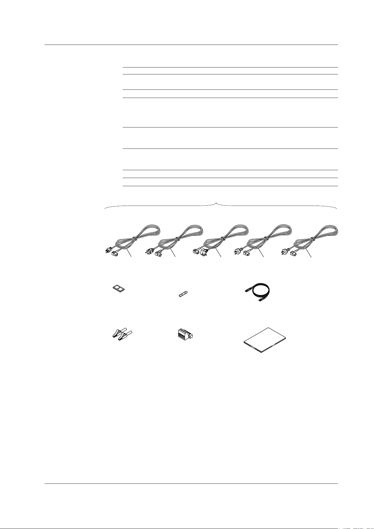
Standard Accessories
Rubber feet
A9088ZM
User’s manual (this manual)
IMGS210-01EN
Measurement lead
2
758933
Alligator clip adaptor set
2
758922
Spare power supply fuse
A1109EF or A1108EF
Terminal plug
3
A2006JT
UL, CSA Standard
A1006WD
VDE Standard
A1009WD
BS Standard
A1054WD
AS Standard
A1024WD
D
F
R
Q
One of these power cords1 is supplied according to the suffix code.
H
GB Standard
A1064WD
The standard accessories below are supplied with the instrument.
Name Model or Part No. Quantity Note
Power cord
page
Rubber feet A9088ZM 1 Two rubber feet in one set.
Spare power supply fuse
Power cord suffix code
-1 or -4
-7 A1108EF 1 250 V, 0.5 A, time lag.
Measurement lead 758933 1 set Safety terminal cable. Red and black, 1
Only included wi
Alligator clip adapter 758922 1 set Safety terminal-to-alligator clip adapter.
Only included wi
Terminal plug A2006JT 1 Only included with the GS211.
User’s manual IMGS210-01EN 1 This manual.
Checking the Contents of the Package
1
See the previous 1
A1109EF 1 250 V, 1 A, time lag.
pc each.
th the GS210.
Red and black, 1 pc each.
th the GS210.
IM GS210-01EN
1 Make sure that the attached power cord meets the designated standards of the country and
area that you are using it in.
2 Only included with the GS210.
3 Only included with the GS211.
iii
Page 6

Checking the Contents of the Package
Optional Accessories (Sold separately)
The optional accessories below are available for purchase separately.
Name Model or Minimum Note
Part No. Q’ty.
Measurement lead 758933 1 Safety terminal cable. Length: 1 m.
Red and black, 1 pc. each.
Measurement lead 758917 1 Safety terminal cable. Length: 0.75 m.
Red and black, 1 pc. each.
Banana plug set 758919 1 set
Small alligator clip adapter 758922
Large alligator clip adapter 758929
Fork terminal adapter 758921
Conversion adapter 758924
Conversion adapter 751512 1 Banana plug-to-binding post adapter.
BNC cable 366924 1 BNC-BNC, length: 1 m.
BNC cable 366925 1 BNC-BNC, length: 2 m.
Safety terminal adapter 758923 1 set Spring clamp type. Red and black, 1
Safety terminal adapter 758931
Terminal plug
Synchronous operation cable 758960
A2006JT 1 For use with the GS211 rear panel
4 mm plug/φ4 mm socket adapter. Red
φ
and black, 1 pc. each.
1 set Safety terminal-to-alligator clip adapter.
Red and black, 1 pc each.
1 set Safety terminal-to-alligator clip adapter.
Red and black, 1 pc each.
1 set Safety terminal-to-fork terminal adapter.
Red and black, 1 pc each.
1 BNC-to-safety terminal adapter.
pc. each.
1 set Screw-in type. Red and black, 1 pc.
each.
terminals.
1 RJ-11 cable, 6 pins, length: 1 m.
iv
IM GS210-01EN
Page 7

Safety Precautions
This instrument is an IEC safety class I instrument (provided with a terminal for protective
earth grounding).
The general safety precautions described herein must be observed during all phases
of operation. If the instrument is used in a manner not specified in this manual, the
protection provided by the instrument may be impaired. Yokogawa Electric Corporation
assumes no liability for the customer’s failure to comply with these requirements.
The following symbols are used on this instrument.
Warning: handle with care. Refer to the user’s manual or service manual.
This symbol appears on dangerous locations on the instrument which require
special instructions for proper handling or use. The same symbol appears in the
corresponding place in the manual to identify those instructions.
Ground (earth) or functional ground terminal (do not use this terminal as a
protective ground terminal).
Alternating current
ON (power)
OFF (power)
In-position of a bi-stable push control
Out-position of a bi-stable push control
Be sure to comply with the precautions below. Not complying might result in
injury or death.
WARNING
Use the Instrument Only for Its Intended Purpose
The GS200 is a generator that can generate DC voltage and current. Do not use
this instrument for anything other than as a DC voltage and current generator.
Check the Physical Appearance
Do not use the instrument if there is a problem with its physical appearance.
Use the Correct Power Supply
Before connecting the power cord, ensure that the source voltage matches the
rated supply voltage of the instrument and that it is within the maximum rated
voltage of the provided power cord.
IM GS210-01EN
Use the Correct Power Cord and Plug
To prevent the possibility of electric shock or fire, be sure to use the power cord
supplied by YOKOGAWA. The main power plug must be plugged into an outlet with
a protective earth terminal. Do not disable this protection by using an extension
cord without protective earth grounding. Additionally, do not use the power cord
supplied with this instrument with another instrument.
v
Page 8

Safety Precautions
Do not use the power cord in a bundled condition. If you use a power plug with
foreign substance on it, insulation may be compromised by humidity or other
factors and may cause a fire. Clean the power plug regularly.
Connect the Protective Grounding Terminal
Be sure to connect the protective earth to prevent electric shock before turning ON
the power. The power cord that comes with the instrument is a three-prong type
power cord. Connect the power cord to a properly grounded three-prong outlet.
Do Not Impair the Protective Grounding
Never cut off the internal or external protective earth wire or disconnect the wiring
of the protective earth terminal. Doing so poses a potential shock hazard.
Do Not Operate with Defective Protective Grounding or Fuse
Do not operate the instrument if the protective earth or fuse might be defective.
Also, make sure to check them before operation.
Do Not Operate in an Explosive Atmosphere
Do not operate the instrument in the presence of flammable gasses or vapors.
Operation in such an environment constitutes a safety hazard.
Do Not Remove the Covers or Disassemble or Alter the Instrument
Only qualified YOKOGAWA personnel may remove the covers and disassemble or
alter the instrument. The inside of the instrument is dangerous because parts of it
have high voltages.
Ground the Instrument before Making External Connections
Securely connect the protective grounding before connecting to the item under
measurement or to an external control unit.
If you are going to touch the circuit, make sure to turn OFF the circuit and check
that no voltage is present.
Measurement Category
The measurement category of the GS200 signal input terminals is Other (O). Do
not use it to measure the main power supply or for Measurement Categories II, III,
and IV.
Installation Location
•
This instrument is designed to be used indoors. Do not install or use it outdoors.
Install the instrument so that you can immediately remove the power cord if an
•
abnormal or dangerous condition occurs.
CAUTION
Operating Environment Limitations
This product is a Class A (for industrial environment) product. Operation of this
product in a residential area may cause radio interference in which case the user is
required to correct the interference.
vi
IM GS210-01EN
Page 9
Waste Electrical and Electronic Equipment
Waste Electrical and Electronic Equipment (WEEE), Directive 2002/96/EC
(This directive is valid only in the EU.)
This product complies with the WEEE Directive (2002/96/EC) marking
requirement. This marking indicates that you must not discard this electrical/
electronic product in domestic household waste.
Product Category
With reference to the equipment types in the WEEE directive
product is classified as a “Monitoring and Control instrumentation” product.
Annex 1, this
Do not dispose
contact your local Yokogawa Europe B. V. office.
in domestic household waste. When disposing products in the EU,
New EU Battery Directive
New EU Battery Directive, DIRECTIVE 2006/66/EC
(This directive is valid only in the EU.)
Batteries are included in this product.
out and collected as ordained in ANNEX II in DIRECTIVE 2006/66/EC.
Battery type
Lithium battery
You cannot replace batteries by yourself. When you need to replace batteries,
contact your local Yokogawa Europe B.V.office.
This marking indicates they shall be sorted
IM GS210-01EN
vii
Page 10
Symbols and Notations Used in This Manual
Safety Markings
The following markings are used in this manual.
Improper handling or use can lead to injury to the user or damage
to the instrument. This symbol appears on the instrument to indicate
that the user must refer to the user’s manual for special instructions.
The same symbol appears in the corresponding place in the user’
s manual to identify those instructions. In the manual, the symbol is
used in conjunction with the word
“
WARNING” or “CAUTION.”
WARNING
CAUTION
Calls attention to information that is important for proper operation of
Note
Calls attention to actions or conditions that could cause serious or
fatal injury to the user, and precautions that can be taken to prevent
such occurrences.
Calls attention to actions or conditions that could cause light injury to
the user or damage to the instrument or user’s data, and precautions
that can be taken to prevent such occurrences.
the instrument.
Notations Used in the Procedural Explanations
On pages that describe the operating procedures in chapters 3 through 15 and the
appendix, the following symbols are used to distinguish the procedures from their
explanations.
Procedure
Explanation
Carry out the procedure according to the step numbers. All
procedures are written under the assumption that you are starting
operation at the beginning of the procedure, so you may not need
to carry out all the steps in a procedure when you are changing the
settings.
This section describes the setup items and the limitations regarding
the procedures. It may not give a detailed explanation of the feature.
For a detailed explanation of the feature, see chapter 2.
<<Corresponding Command Mnemonic>>
Indicates a communication command that corresponds to the feature described on the
procedural explanation page.
Characters and Terminology Used in Procedural Explanations
Keys
Bold characters used in the procedural explanations indicate characters that are marked
on the panel keys.
NUM LOCK + or
This means the following: press the NUM LOCK key to make it illuminate, and then press
the
or key. When the instrument is in this state, you can use the and keys to
directly access the items that are marked above and below these keys (numbers 0 to 9,
period, and BS).
viii
IM GS210-01EN
Page 11

Contents
3
2
1
4
5
6
7
8
9
10
11
12
13
14
15
App
Index
Checking the Contents of the Package.............................................................................................ii
Safety Precautions ............................................................................................................................v
Waste Electrical and Electronic Equipment .................................................................................... vii
New EU Battery Directive ...............................................................................................................vii
Symbols and Notations Used in This Manual ................................................................................ viii
Chapter 1 Component Names and Functions
1.1 Front Panel ....................................................................................................................... 1-1
1.2 Rear Panel ....................................................................................................................... 1-2
1.3 Display Mode and Displayed Contents ............................................................................ 1-3
1.4 Keys
................................................................................................................................. 1-5
Chapter 2 Features
2.1 SystemConguration ....................................................................................................... 2-1
ProductFeaturesandSystemConguration ................................................................ 2-1
2.2 Source Feature and Measurement Feature (Monitoring fe
2.3 Source .............................................................................................................................. 2-6
Source Range ...............................................................................................................
Source Function ............................................................................................................
Source Action ................................................................................................................
Output ON/OFF .............................................................................................................
DUT Protection Using Limiters ...................................................................................... 2-8
Local Sense and Remote Sense .................................................................................. 2-9
Guard Terminal Feature .............................................................................................. 2-10
2.4
Programs
Program Feature .......................................................................................................
Program Interval Time ..................................................................................................2-11
Program Slope Time ....................................................................................................2-11
Repeating Programs ................................................................................................... 2-12
Program Triggers ......................................................................................................
Program Files ..............................................................................................................
Executing Programs .................................................................................................... 2-14
2.5 Measurement (Monitoring feature; /MON option) ........................................................... 2-16
Measurement Function and Measurement Range ......................................................
Measurement ON/OFF ............................................................................................... 2-16
Measurement Operation ............................................................................................. 2-16
Measurement Delay .................................................................................................... 2-17
Highly Accurate Measurement and High-Speed Measurement .................................. 2-17
NULL Computation ...................................................................................................... 2-17
Store/Recall (Statistical Computation Value Display).................................................. 2-18
2.6
riggering ....................................................................................................................... 2-20
T
Overview ......................................................................................................
Program Triggers ........................................................................................................
Measurement Triggers (/MON option) ........................................................................ 2-21
Trigger Block Diagram ................................................................................................ 2-22
Trigger Output ......................................................................................................
Trigger Hold ................................................................................................................
Sampling Error ............................................................................................................
.........................................................................................................................2-11
ature; /MON option) ............... 2-3
2-6
2-7
2-7
2-8
2-11
...
2-12
..
2-13
2-16
.......
2-20
2-20
2-23
2-23
2-23
...............
IM GS210-01EN
ix
Page 12

Contents
2.7 Synchronization .............................................................................................................. 2-24
Synchronization ..........................................................................................................
External I/O .................................................................................................................
2.8 Other Features ............................................................................................................... 2-25
USB Storage Feature .................................................................................................. 2-25
USB Communication (USB-TMC command control) .................................................. 2-26
Ethernet Communications (/C10 option) ..................................................................... 2-27
GP-IB Communications .............................................................................................. 2-27
Saving, Loading, and Deleting Setup Data ................................................................. 2-27
Selecting the Settings Applied at Power-On ............................................................... 2-27
Chapter 3 Instrument Preparation and Common Operations
3.1 Handling Precautions ....................................................................................................... 3-1
3.2 Installation ........................................................................................................................ 3-3
3.3 Connecting the Power Supply .......................................................................................... 3-6
3.4 Turning the Power Switch On and Off .............................................................................. 3-7
3.5 Wiring Precautions ........................................................................................................... 3-8
3.6 Wiring the GS211 Rear Panel Terminal Plug .................................................................... 3-9
3.7 Setting the Date,
Time, and the Time Difference from GMT (Greenwich Mean Time) ... 3-10
Chapter 4 Common Settings
4.1 Basic Key Operations and How to Enter Values .............................................................. 4-1
4.2 Selecting the Wiring System (Remote Sense or Local Sense) ........................................ 4-3
4.3 Setting the Guard Terminal ............................................................................................... 4-5
4.4 USB Storage Feature ......................................................................................................
2-24
2-24
. 4-7
Chapter 5 Source
5.1 Setting the Source Function ............................................................................................. 5-1
5.2 Setting the Source Range ................................................................................................ 5-2
5.3 Setting the Source Level .................................................................................................. 5-3
5.4 Setting the Limiter ......................................................................................................
5.5 T
urning the Output On and Off ......................................................................................... 5-5
Chapter 6 Programs
6.1 Turning Program Repetition Mode On and Off ................................................................. 6-1
6.2 Setting the Program Interval Time .................................................................................... 6-2
6.3 Setting the Program Slope
6.4 Setting the Program
6.5 Creating and Editing Programs ........................................................................................ 6-5
6.6 Saving and Loading Programs ......................................................................................... 6-8
6.7 Executing Programs ......................................................................................................
Trigger (/MON option) ...................................................................... 6-4
Chapter 7 Measurement (Option)
7.1 Turning Measurement On and Off .................................................................................... 7-1
7.2 Setting the Integration Time ............................................................................................. 7-2
7.3 Setting the Measurement Delay ....................................................................................... 7-3
7.4 Selecting the Measurement
7.5 Setting the Measurement
7.6 T
7.7 Zero Calibration (Zero reference measurement) .............................................................. 7-7
7.8 Storing Measured Results ................................................................................................ 7-8
7.9 Performing Statistical Computations on Measured V
urning the NULL Computation On and Off ..................................................................... 7-6
...... 5-4
Time ...................................................................................... 6-3
. 6-12
Trigger ................................................................................. 7-4
Timer ....................................................................................... 7-5
alues (Recall) ............................... 7-10
x
IM GS210-01EN
Page 13

Contents
3
2
1
4
5
6
7
8
9
10
11
12
13
14
15
App
Index
Chapter 8 Synchronous Operation
8.1 Synchronous Operation Using the BNC I/O Terminals (IN and OUT) .............................. 8-1
8.2 Using the RJ-11 Connectors (SYNC IN and SYNC OUT) to Perform Synchronous
Operation ..........................................................................................................................
8-4
Chapter 9 Other Features
9.1 Initializing Setup Data ....................................................................................................... 9-1
9.2 Saving, Loading, and Deleting Setup Data ...................................................................... 9-2
9.3 Selecting the Settings
9.4 Selecting the Display Brightness,
Sound On and Off
9.5 Selecting the CSV File Format ......................................................................................... 9-6
9.6 Error Log Display .......................................................................................................
Applied at Power-On ..................................................................... 9-4
Turning the Display Off, and Turning the Beep
............................................................................................................. 9-5
....... 9-7
Chapter 10 USB Interface
10.1 USBInterfaceFeaturesandSpecications .................................................................... 10-1
10.2 Setting the USB Interface Mode ..................................................................................... 10-2
10.3 V
iewing the VISA Setup Information............................................................................... 10-3
Chapter 11 Ethernet Interface (Option)
11.1 EthernetInterfaceFeaturesandSpecications ..............................................................11-1
11.2 Connecting to a Network .................................................................................................11-2
11.3
11.4
11.5
ConguringNetworkSettings(TCP/IP) ...........................................................................11-3
Viewing the Network Settings ..........................................................................................11-6
Web Server Feature ........................................................................................................11-7
Chapter 12 GP-IB Interface
12.1 GP-IBInterfaceFeaturesandSpecications ................................................................. 12-1
12.2 Connecting the GP-IB Cable .......................................................................................... 12-2
12.3 Setting the GP-IB
12.4 7651-Compatible Mode .................................................................................................. 12-4
12.5 Responses to Interface Messages ................................................................................. 12-5
12.6 About the IEEE 488.2-1992 Standard ............................................................................ 12-7
Address and Command Mode ........................................................... 12-3
Chapter 13 Communication Commands
13.1 Program Format ............................................................................................................. 13-1
13.1.1 Symbols Used in the Syntax ............................................................................ 13-1
13.1.2 Messages ........................................................................................................ 13-1
13.1.3 Commands ...................................................................................................... 13-3
13.1.4 Responses ....................................................................................................... 13-5
13.1.5 Data
13.2 Commands ......................................................................................................
13.2.1 List of Commands ............................................................................................ 13-7
13.2.2 Output Commands (OUTPut group) .............................................................. 13-10
13.2.3 Source Commands (SOURce group) .............................................................13-1
13.2.4 Program Commands (PROGram group) ....................................................... 13-13
13.2.5 Measurement Commands (SENSe group) .................................................... 13-15
13.2.6 Measured V
groups)
13.2.7 Store/Recall Commands (TRACe group) ...................................................... 13-18
13.2.8 External I/O Commands (ROUT
13.2.9 System Commands (SYST
................................................................................................................. 13-5
alue Read Commands (INITiate, FETCh, READ, and MEASure
........................................................................................................... 13-17
............... 13-7
1
e group) ....................................................... 13-20
em group) ............................................................ 13-21
IM GS210-01EN
xi
Page 14

Contents
13.2.10 Status Commands (STATus group) ............................................................... 13-23
13.2.11 Common Commands ..................................................................................... 13-24
13.3 Status Reports
13.3.1 Status Reports
13.3.2 Status Byte
13.3.3 Standard Event Register................................................................................
13.3.4 Extended Event Register ............................................................................... 13-30
13.3.5 Output Queue and Error Queue .................................................................... 13-31
.............................................................................................................. 13-26
............................................................................................... 13-26
.................................................................................................... 13-28
Chapter 14 Troubleshooting and Maintenance
14.1 Troubleshooting .............................................................................................................. 14-1
14.2 Error Code Descriptions and Corrective Actions ............................................................ 14-3
14.3 Self-T
14.4 V
14.5 Updating the System Firmware ...................................................................................... 14-9
14.6 Changing the Power Fuse .............................................................................................14-11
14.7 Recommended Replacement Parts and Maintenance ................................................. 14-12
est ......................................................................................................................... 14-6
iewing the Product Information..................................................................................... 14-8
Chapter 15 Specications
15.1 Source Section ............................................................................................................... 15-1
15.2 Measurement Section (On models with the /MON option) ............................................. 15-3
15.3 Features
15.4 External I/O Section (BNC (IN/OUT) and I/O for synchronous operation
(SYNC IN/OUT))
15.5 Interface
15.6 General
15.7 External Dimensions ...................................................................................................... 15-8
......................................................................................................................... 15-3
.............................................................................................................
......................................................................................................................... 15-5
Specications ................................................................................................... 15-6
13-29
15-4
Appendix
Index
Appendix 1 Factory Default Settings .....................................................................................App-1
Appendix 2 Block Diagram ....................................................................................................App-2
xii
IM GS210-01EN
Page 15
1
GS200
DC VOLTAGE/CURRENT SOURCE
SAMPLE
ERROR
REPEAT
STORE
REMOTE
ERROR
LOCAL
ESC
POWER
NUM
LOCK
1 2 3 4 5BSRANGE
6 7 8 9 0
UTILITY
SETUP
LIMIT
MEASURE
PROGRAM
END
DEL
HOLD
STEP
RUN
PROGRAM
OUTPUT
V
mV
mA
SRQ
ENTER
SENSE OUTPUT
32V
MAX
0.5V
MAX
32V
200mA
MAX
Hi
Lo
42V
10mA
PEAK
G
G TERM 250 V PEAK TO
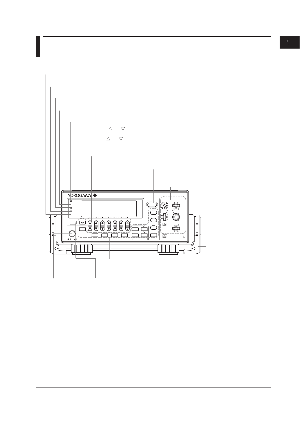
Power switch
→ Section 3.4
Handle
Used to carry the GS200.
→ Section 3.2
Output terminals (only on the GS210)
Used to connect the included measurement leads.
→ Sections 3.5, 4.2, and 4.3
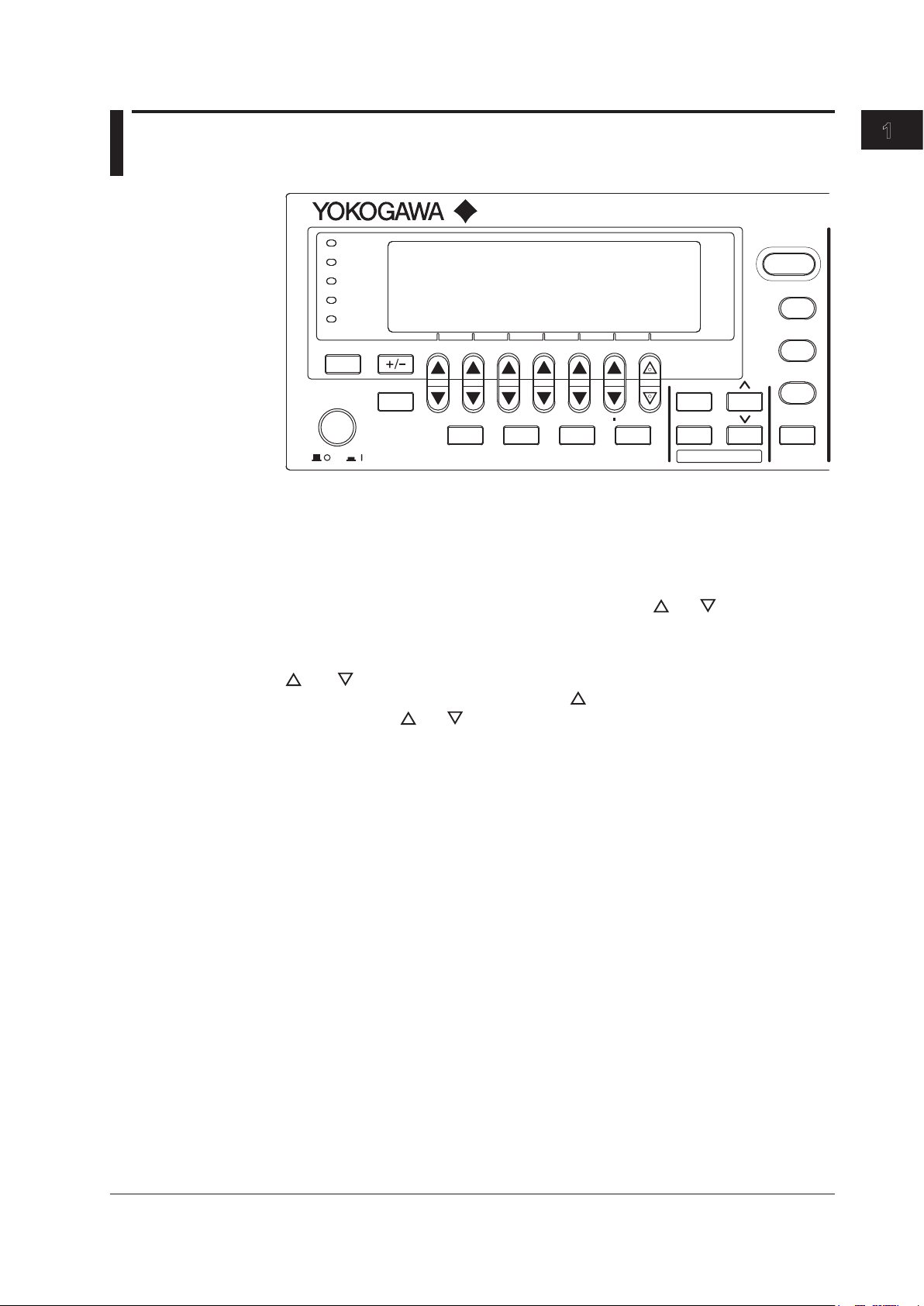
Soft keys, and
keys, and the keypad
• Use the soft keys to select items on the soft key menus that appear during configuration.
• Use the and keys to increase and decrease each digit of the displayed value during numeric
input.
• Use the keypad to specify a value directly during numeric input.
→ Section 4.1
ESC (LOCAL) key
Switches the display or clears a soft key menu → Section 4.1
Setup and execution keys
These keys are used to change settings or execute operations.
Press a setup key to show the respective setup item. → Sections 1.4 and 4.1
Remote indicator
Illuminates when the GS200 is in remote mode (controlled through communications) → Section 12.1
Store indicator
Illuminates when store mode is turned on → Section 7.8
Sampling error indicator
Illuminates when a sampling error occurs in a program or measurement trigger → Sections 6.4 and 7.4
Repeat indicator
Illuminates when the program’s repeat mode is turned on → Section 6.1
Output control key
Press to turn the source on and off. → Section 5.5
Error indicator
Illuminates when there are errors in the error log → Section 14.2
Chapter 1 Component Names and Functions
1.1 Front Panel
Component Names and Functions
IM GS210-01EN
1-1
Page 16
1.2 Rear Panel
LINK
ACT
ETHERNET
100BASE-TX
IN
OUT USB
SYNC
IN
OUT
100V AC
80 VA MAX
50/60 Hz
FUSE 250 V T 1A
GP-IB(IEEE 488
)
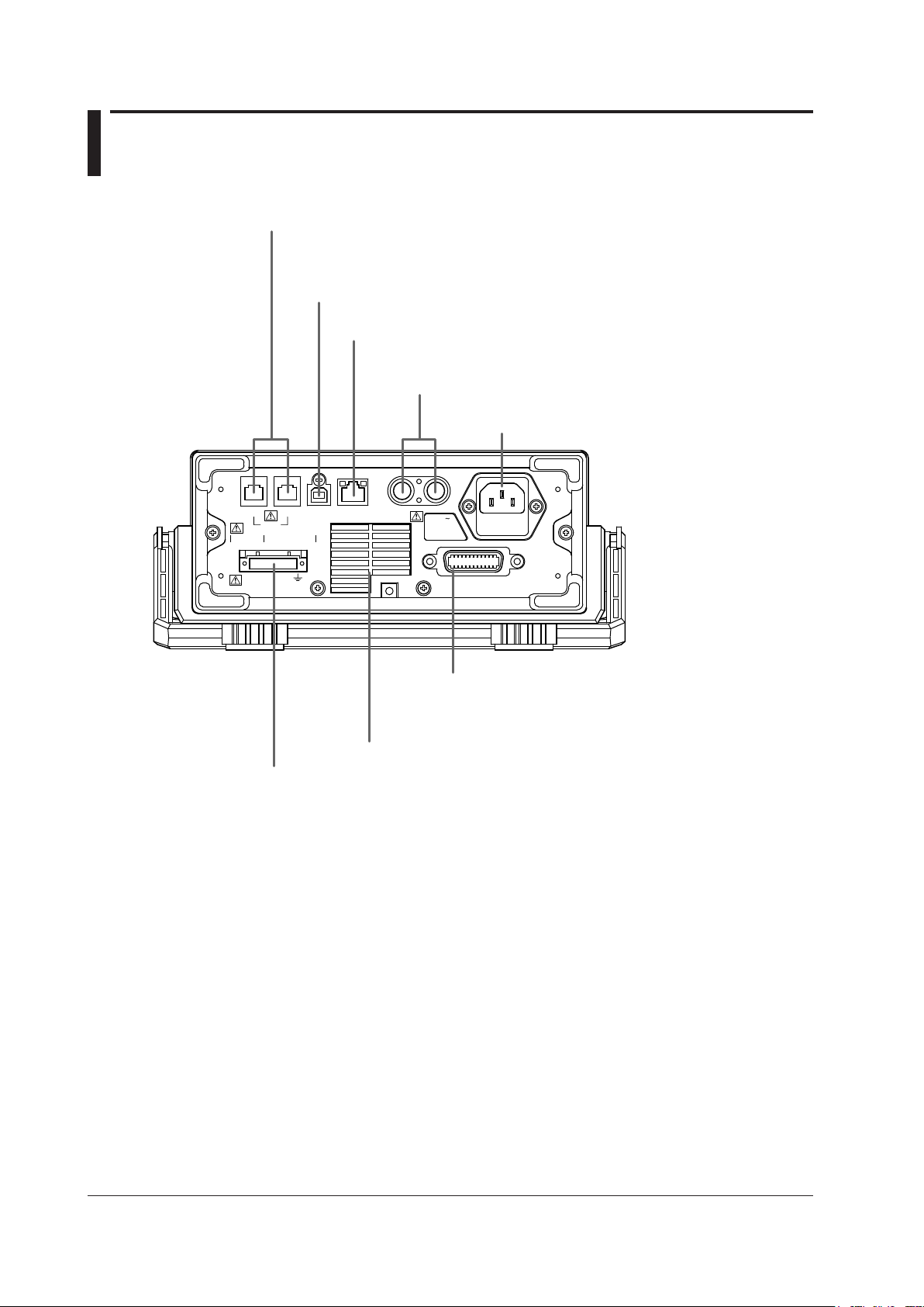
Cooling fan → Section 3.2
USB port
Used to connect the GS200 to a PC that has a USB interface and to access the GS200
as USB storage or to control the GS200 through USB-TMC commands.
→ Sections 4.4 and 10.2
I/O terminals for synchronous operation
Used to connect multiple GS200s and perform synchronous operation. → Section 8.2
Ethernet port
Used to connect the GS200 to a network. → Section 11.2
BNC I/O terminals
Used to receive and transmit trigger, output state, and source
change completion signals. → Section 8.1
Power inlet
Connects to a power supply → Section 3.3
GP-IB connector
Used when controlling the GS200 with commands
through the GP-IB interface. → Section 12.2
Output terminal (only on the GS211)
Used to connect the DUT cable. → Sections 3.5, 3.6, 4.2, and 4.3
*
1-2
IM GS210-01EN
* Only on models with the Ethernet option (/C10).
Page 17
1
1.3 Display Mode and Displayed Contents
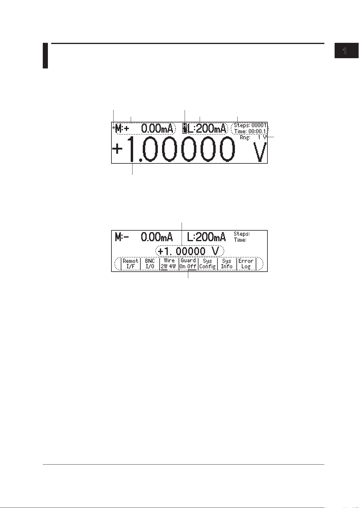
Limiter indicators
H: High limiter
L: Low limiter
Limit
Measured value
1
Source level
Source range
Program execution status
Measurement sample
indicator
1
Source level
Menu items
Display Mode
Main Screen
1 This is displayed on models with the monitoring (/MON) option.
Menu Screen
Component Names and Functions
Displayed Contents
Source Level
The source level that is being produced is displayed here.
Measurement Sample Indicator (On models with the /MON option)
During measurement, an asterisk illuminates. When the measurement completes, the
asterisk turns off. If you are performing sequential measurements that have a short
integration time, the asterisk illuminates and turns off once every 100 ms.
Measured Value (On models with the /MON option)
When the source function is set to voltage, this displays the measured current. When the
source function is set to current, this displays the measured voltage. When there is no
measured value, “-------” is displayed. When the source range is set to 10 mV or 100 mV,
you cannot use the measurement (monitoring) feature. In these situations, the message
“Cannot measure in mV source range” is displayed. When the measurement feature is
turned off, “Off” is displayed.
On models without the monitoring (/MON) option, nothing is displayed in the measured
value area.
IM GS210-01EN
1-3
Page 18
1-4
IM GS210-01EN
1.3 Display Mode and Displayed Contents
Limits
When the source function is set to voltage, this displays the current limit. When the
source function is set to current, this displays the voltage limit. When the source range
is set to 10 mV or 100 mV, the limit is fixed to 200 mA (you cannot change this value). In
these situations, “------mA” is displayed for the limit.
Note
In voltage source mode’s 10 mV and 100 mV ranges, the output resistance is approximately 2
. Therefore, these ranges are not suitable when the GS200 is connected to a load that allows
Ω
current to flow (a low-impedance load). Connect a load that allows as little current to flow as
possible (a high-impedance load).
Limiter Indicators
•
is displayed when the high limiter is activated.
•
is displayed when the low limiter is activated.
Program Execution Status
When a program is running, the following items are displayed.
•
Steps:
• Time: The remaining interval time (minutes:seconds.tenths of seconds).
The step number that is currently being executed.
Source Range
The source range that is currently in use is displayed here.
Page 19
1
1.4 Keys
GS200
DC VOLTAGE/CURRENT SOURCE
SAMPLE
ERROR
REPEAT
STORE
REMOTE
ERROR
LOCAL
ESC
POWER
NUM
LOCK
1 2 3 4 5
BS
RANGE
6 7 8 9 0
UTILITY
SETUP
LIMIT
MEASURE
PROGRAM
END
DEL
HOLD
STEP
RUN
PROGRAM
OUTPUT
V
mV
mA
SRQ
ENTER
General-Purpose Keys
+/- Key (Section 4.1)
This key is used when you enter numeric values or change a value’s sign.
NUM LOCK Key (Section 4.1)
When you press the NUM LOCK key, the NUM LOCK key’s indicator illuminates, and the
GS200 enters keypad mode. In this mode, you can use the
access the items that are marked above and below these keys (numbers 0 to 9, period,
and BS).
and keys to directly
Component Names and Functions
and Keys (Section 4.1)
When a soft key menu is displayed, press the keys to make selections and perform
actions. Press the
mode.
ENTER Key (Section 4.1)
When the GS200 is in keypad mode, press this key to enter the setting that you have
specified.
ESC (LOCAL) Key (Section 4.1)
When a menu is displayed, press this key to display the previous menu (to move up one
level in the menu hierarchy). If you press this key when you are entering a value with
the GS200 in up/down key mode, the GS200 returns to one screen before the numeric
value input screen. When the GS200 is displaying the top menu, you can press this key
to switch between the top menu and the main screen. This is also the LOCAL key. When
the GS200 is in remote mode, you can press this key to return it to local mode.
and keys to enter values in up/down key mode and keypad
IM GS210-01EN
1-5
Page 20
1-6
IM GS210-01EN
1.4 Keys
Source Keys
V Key (Sections 5.2 and 5.3)
If you press this key when the GS200 is in up/down key mode and is displaying the main
screen, the source function is set to voltage, and the source range is set to 1 V. If you
press this key when the GS200 is in keypad mode and is displaying the main screen, the
voltage source level that you specified is fixed, the source function is set to voltage, and
the source range is set to the most appropriate range greater than or equal to the 1 V
range.
mV Key (Sections 5.2 and 5.3)
If you press this key when the GS200 is in up/down key mode and is displaying the
main screen, the source function is set to voltage, and the source range is set to 10 mV
(the circuit that produces the 10 mV range uses the voltage divider). If you press this
key when the GS200 is in keypad mode and is displaying the main screen, the voltage
source level that you specified is fixed, the source function is set to voltage, and the
source range is set to the most appropriate range.
mA Key (Sections 5.2 and 5.3)
If you press this key when the GS200 is in upd/down key mode and is displaying the
main screen, the source function is set to current and the source range is set to 1 mA. If
you press this key when the GS200 is in keypad mode and is displaying the main screen,
the current source level that you specified is fixed, the source function is set to current,
and the source range is set to the most appropriate range.
RANGE Keys (Section 5.2)
Press these keys to change the source range. Press the
range by one. Press the
displayed, you can use the
range continuously by holding these keys down.
Depending on the operation menu, these keys may be used to scroll the screen. In these
situations, you can scroll the screen by holding these keys down.
key to decrease the source range by one. When a menu is
key as a menu selection soft key. You cannot change the
key to increase the source
LIMIT Key (Section 5.4)
Press this key to display the limit input screen. If you press this key in keypad mode
when you are entering a limit, the limit that you specified is discarded, and the GS200
returns to the main screen.
OUTPUT Key (Section 5.5)
Output turns on and off each time that you press the OUTPUT key. When output is
turned on, this key illuminates in red. When output is turned off, this key turns off. When
you turn output on, the display switches to the main screen.
Page 21

1
Program Keys
PROGRAM Key (Chapter 6)
Press this key to display the program menu. If you press this key while you are editing a
program, program editing finishes.
RUN Key (Section 6.7)
Press this key to execute the program from its first step.
STEP Key (Section 6.7)
Press this key to execute just one of the program’s steps.
HOLD Key (Section 6.7)
Press this key to pause the program that is running. If you press this key while the
program execution is paused, the program resumes executing.
If you execute a program by pressing the RUN, STEP, or HOLD key, the display switches
to the main screen.
Measurement (Monitoring) Key (Option)
MEASURE Key (Chapter 7)
Press this key to display the measurement setup menu. On models without the
monitoring (/MON) option, if you press the MEASURE key, “Not Available” appears.
1.4 Keys
Component Names and Functions
Setup Information Key
SETUP Key (Sections 9.1, 9.2, and 9.3)
Press this key to list setup files and display the SETUP menu.
Communication, System Setup, and Other Keys
UTILITY Key
Press this key to display the UTILITY menu. Use the UTILITY menu to access the
following settings and features:
• Communication settings (section 4.4 and chapters 10, 1
• Terminal settings (sections 4.2, 4.3, and 8.1).
• System settings (section 3.7, 4.4, and 15.5 and chapter 9).
• Self-test (section 15.3).
• Product information (section 15.4).
• Error log (section 9.6).
1, and 12).
IM GS210-01EN
1-7
Page 22

Chapter 2
2
1
Features
2.1 System Configuration
Product Features and System Configuration
GS200 Features
• The GS200 uses dual D/A conversion to produce voltage and current with high
accuracy and resolution. It can produce stable current or voltage whether it is used for
a short or long period of time and maintains superb linearity over all the ranges. You
can also use the GS200 to produce voltage and current that has low noise.
•
The GS200 can perform four-quadrant operation by operating
current sink in the range of ±32 V and ±200 mA.
• The GS200 has an optional voltage and current measurement
feature). The GS200 can measure current in voltage source mode and measure
voltage in current source mode. The display resolution is 4½ digits.
• By using the program feature, you can specify up to 10000 ste
controls the generation of voltage or current. You can also generate ramp waveforms
by using the slope setting.
• Y
ou can use the external I/O BNC connector on the rear panel to control multiple
GS200s or other measuring instruments by synchronizing them to actions such as the
source action and the output action.
• The I/O terminals for synchronous operation (SYNC IN/OUT) o
be connected in a daisy chain to allow synchronization of output control and triggers.
This increases the number of channels that can be controlled.
• The GS200 has a built-in 4 MB non-volatile storage disk (GS2
various settings and a 16 MB volatile storage disk (GS200RAM) for storing data such
as measurement results. If you use USB to connect the GS200 to a PC, you can
access these storage disks as the PC’s external drives. Because settings and results
are saved to general text files or .CSV files, you can use software such as a text editor
or a general-purpose spreadsheet application to edit these files or use them to display
graphs on your PC.
In addition to the storage feature, the USB interface can be us
control by way of the USB-TMC protocol. Furthermore, command control can be
performed by way of other communication interfaces such as GP-IB, and Ethernet
(VXI-1
1 protocol/7655 command socket).
Y
ou can also use the Ethernet interface to access the GS200’
FTP (the FTP server feature) and to display the GS200’s information and control
it from a Web browser by accessing the GS200 through HTTP (the HTTP server
feature).
Features
as a current source or a
feature (monitoring
ps, each of which
f multiple GS200s can
00ROM) for storing
ed to perform command
s internal disks through
IM GS210-01EN
2-1
Page 23
GP-IB
USB
(
USB-TMC
)
Ether
(
VXI-11
)
GS200
RAM
GS200
ROM
Internal storage
High
GS200
Low
TRIG
OUTPUT
TRIG
OUTPUT
Use the USB storage
feature to connect the
GS200 to a PC as the
PC’s external disk.
PC
Command
control
Communication
line
SYNC OUT
Analog
I/O
SYNC IN
OUTPUT
High Low
SENSE
DUT
BNC OUT
BNC IN
TRIG
OUTPUT
TRIG
OUTPUT
READY
READY
GS200 GS200 GS200
SYNC
IN OUT
SYNC
IN OUT
SYNC
IN OUT
2.1 System Configuration
2-2
IM GS210-01EN
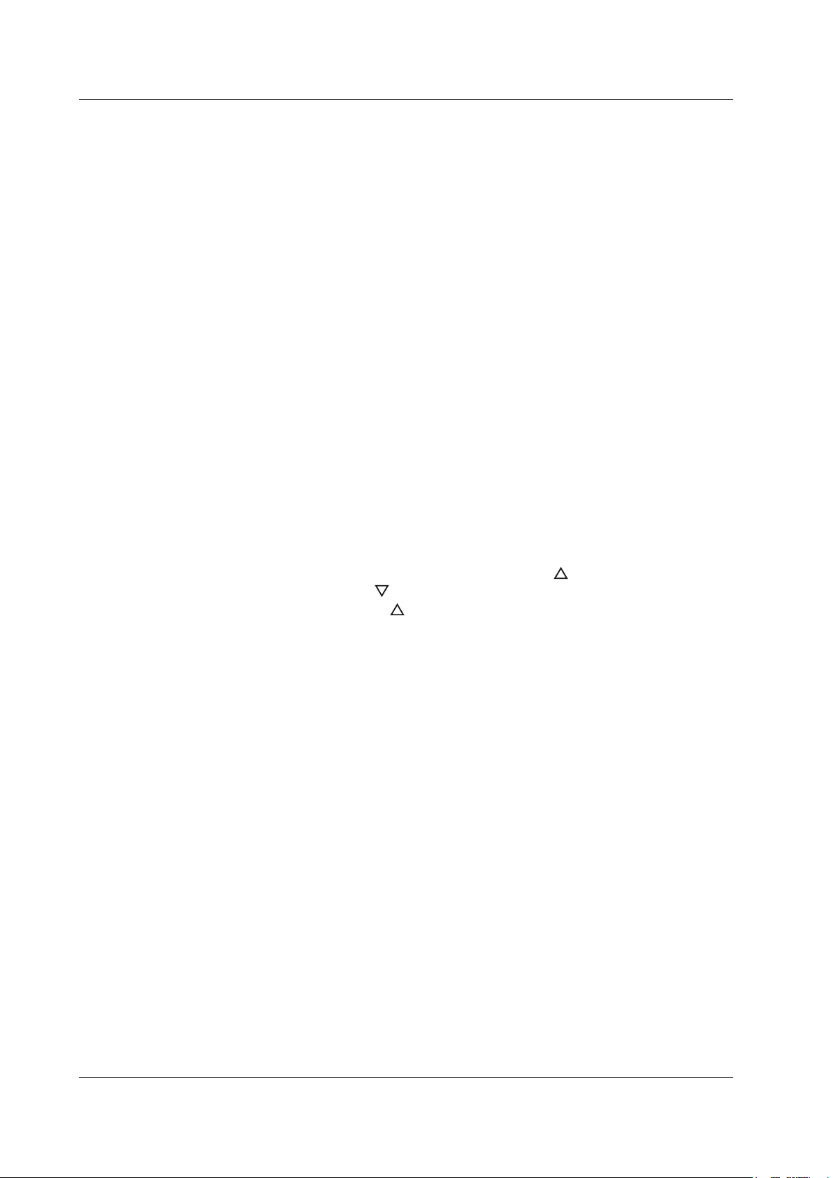
System Configuration Diagram
Synchronous Operation by Connecting the I/O Terminals for Synchronous
Operation (SYNC IN/OUT)
Page 24
2.2 Source Feature and Measurement Feature
+
-
+
-
1
n
+
V, mA V, mA
mV mV
V, mV
mA
Voltage divider
Power amplifier
Dual D/A converter
Hi
Lo
Shunt resistor
Most
significant bits
D/A
Least
significant bits
D/A
2
1
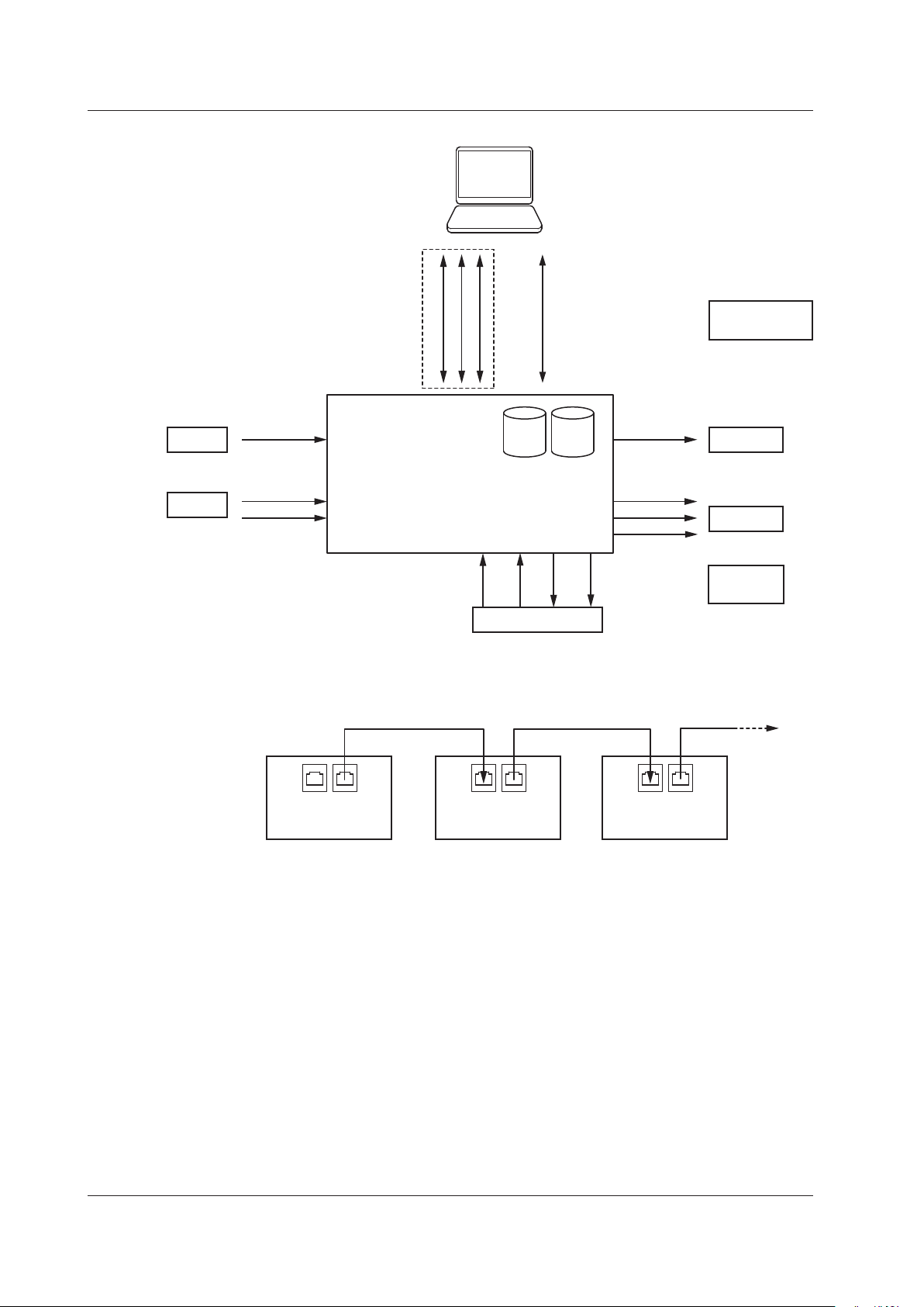
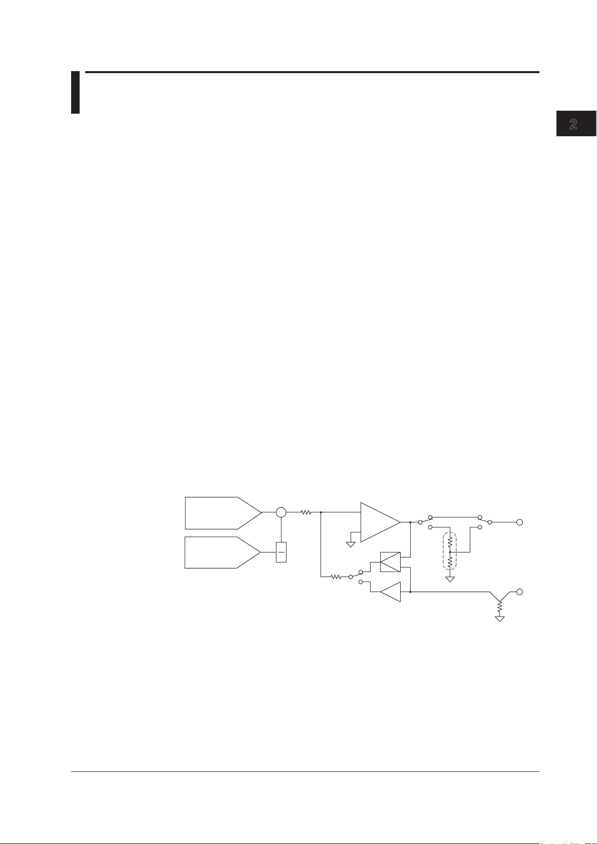
(Monitoring feature; /MON option)
This section explains the basic features of the GS200: the source feature and the
measurement feature (monitoring feature).
Generating Voltage and Current
The GS200 uses dual D/A conversion and a highly accurate power amplifier. This
enables you to set the voltage and current at a resolution of 5½ digits.
Voltage Source
The GS200 has 10 mV, 100 mV, 1 V, 10 V, and 30 V ranges. You can specify and
generate a positive or negative voltage of up to 32 V.
Current Source
The GS200 has 1 mA, 10 mA, 100 mA, and 200 mA ranges. You can specify and
generate a positive or negative current of up to 200 mA.
The 1 V, 10 V, and 30 V voltage source ranges enable you to generate a positive or
negative output current of up to 200 mA with a low output resistance. These ranges are
well-suited to situations such as the evaluation of devices that require current.
When you select the 10 mV or 100 mV range, the GS200 uses a voltage divider that
consists of a pair of resistors. This enables you to use the GS200 to generate low
voltages at resolutions as low as 100 nV or as a 3 μVp-p*, low-noise voltage signal
source. These ranges are well-suited to providing simulated signals to instruments such
as sensors.
In current source mode, you can generate a positive or negative output voltage of 30 V
on all of the current ranges. Current source mode is well-suited to evaluating the charge/
discharge characteristics of rechargeable batteries and other devices.
* 10 mV range, DC to 10 Hz
Features
IM GS210-01EN
2-3
Page 25
200 mA
–32 V 32 V
–200 mA
Current
Voltage
Source
Sink
Sink
Source
Voltage
source
GS200
Load
Source Operation Example
I
Current
source
GS200
Battery
Sink Operation Example
I
2.2 Source Feature and Measurement Feature (Monitoring feature; /MON option)
2-4
IM GS210-01EN
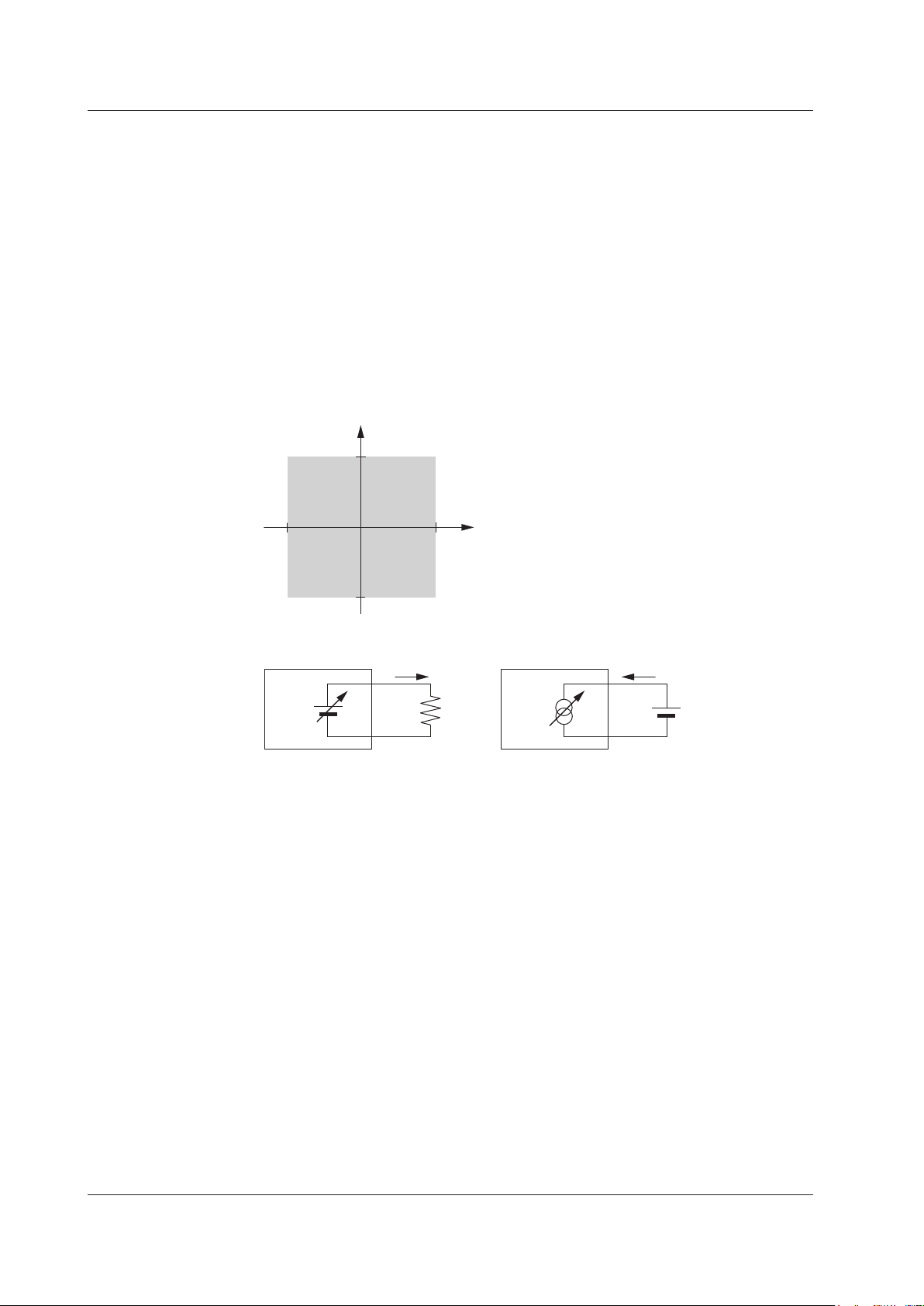
Source and Sink Operations
The GS200 can perform four-quadrant operation by operating as a current source or a
current sink in the range of ±32 V and ±200 mA.
During sink operation, the GS200 operates in the same quadrants as it does during
source operation, so you can use it not just as a true constant voltage source but also as
a highly accurate electronic load.
V
oltage ranges:
1 V, 10 V, and 30 V
Maximum output current: ±200 mA (at 1 V, 10 V, and 30 V ranges)
Current ranges: 1 mA, 10 mA, 100 mA, and 200 mA
Maximum output voltage: ±30 V
Voltage and Current Generation Region
Bipolar Output
Because the GS200 inverts the signal polarity and produces the signal without the use
of a mechanical contact, no abnormal voltage (or current) is generated when the polarity
is inverted. Therefore, the GS200 can generate continuous, variable output ranging
from the maximum negative value to the maximum positive value. This is effective when
you want to invert the polarity to generate program output or evaluate zero-crossing
comparators. Additionally, when you change settings within the same range, glitches are
not generated.
Page 26
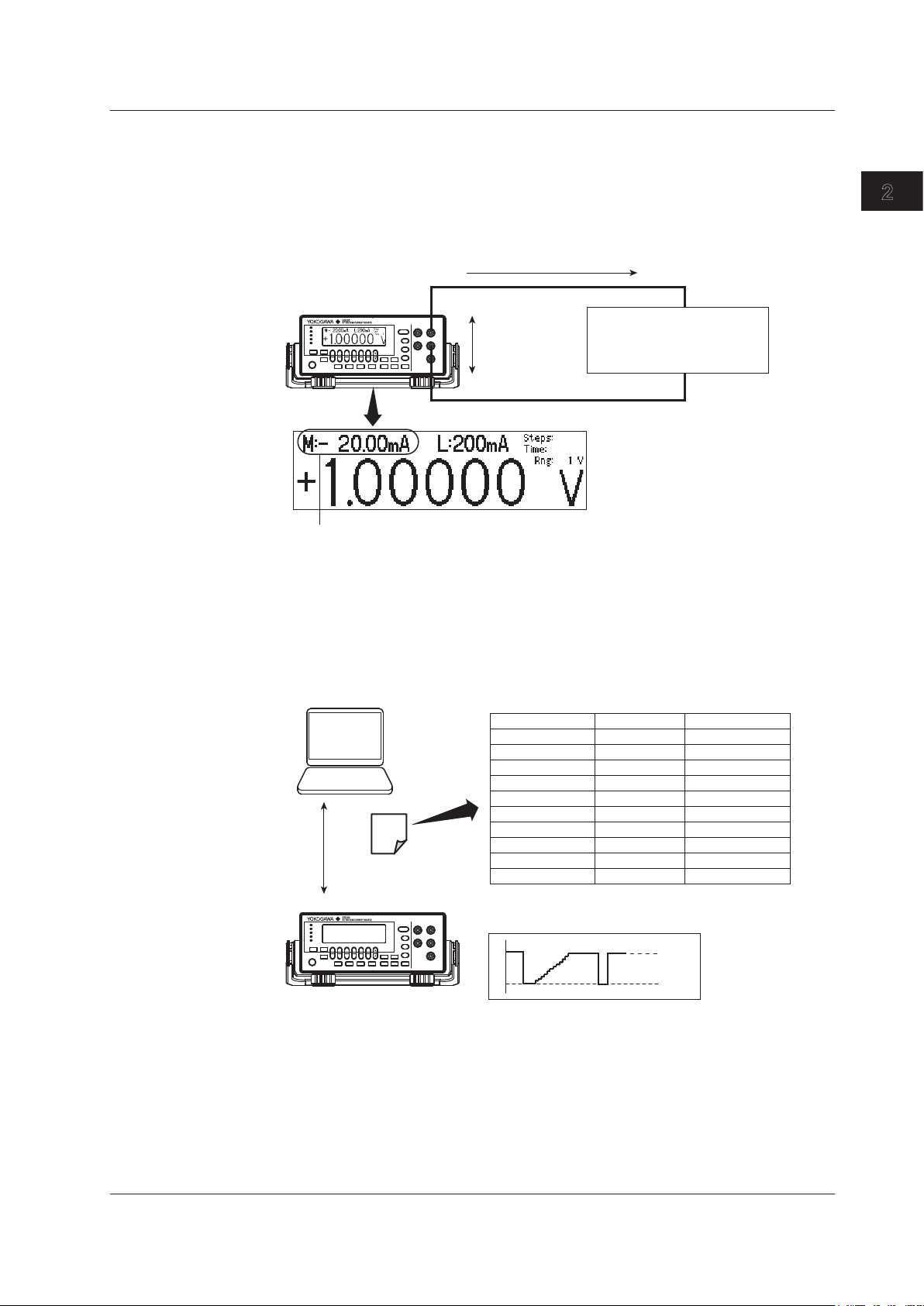
The monitoring feature can be used to:
• Check that current is flowing.
• Check and inspect current consumption.
• Log fluctuations in the load current.
• Record V-I characteristics.
DUT
• Resistance
• Diodes and transistors
• Other electronic parts
Load current measurement
GS200
Vcc application
Edit the output pattern on a spreadsheet, and copy
the data to the internal memory.
GS200
USB
PC
Program file
(CSV format)
Up to 10000 steps
Source Value (V)
1.00
1.01
1.02
1.03
1.04
1.05
1.06
1.07
1.08
1.09
Source Range
10
10
10
10
10
10
10
10
10
10
Source Function
V
V
V
V
V
V
V
V
V
V
2
1
2.2 Source Feature and Measurement Feature (Monitoring feature; /MON option)
Voltage and Current Measurement Feature (Monitoring feature; /MON option)
The GS200 can measure voltage or current while it generates voltage or current. In
voltage source mode, you can measure current with a display resolution of 4½ digits. In
current source mode, you can measure voltage with a display resolution of 4½ digits. You
can use the store feature to save the measured value together with the source value to
the internal RAM disk.
Features
Using up to 10000 Steps to Program the Output
IM GS210-01EN
You can use the program feature to specify up to 10000 output steps. You can edit
programs from the GS200 or create program files in CSV format on a PC and use the
USB storage feature to load the files on the GS200.
For details on programs, see section 2.4, “Programs.”
2-5
Page 27

2.3 Source
200 mA
–32 V 32 V
–200 mA
Current
Voltage
V
I
30 V/200 mA
range
10 V/200 mA
range
1 V/200 mA
range
Range Source Range Resolution Max. Load Current
10 mV ±12.0000 mV 100 nV --------
*
100 mV ±120.000 mV 1 µV --------
*
1 V ±1.20000 V 10 µV ±200 mA
10 V ±12.0000 V 100 µV ±200 mA
30 V ±32.000 V 1 mV ±200 mA
2-6
IM GS210-01EN
Source Range
Source Range
The following figure indicates the range that the GS200 can generate.
Voltage Source Range (See section 5.2 for the procedure)
The following voltage source ranges are available.
* In voltage source mode’s 10 mV and 100 mV ranges, because the GS200 uses a voltage
divider, the output resistance is approximately 2 Ω. Therefore, these ranges are not suitable
when the GS200 is connected to a load that allows current to flow (a low-impedance
load). Depending on the load current, the output voltage may decrease. Also, four-terminal
connection does not function for these voltage ranges. You must use the two-terminal
connection instead. Connect a high-impedance load, a load that is sufficiently larger than the
output resistance.
Page 28
V
I
100 mA/30 V range
10 mA/30 V range
1 mA/30 V range
Range Source Range Resolution Max. Load Current
1 mA ±1.20000 mA 10 nA ±30 V
10 mA ±12.0000 mA 100 nA ±30 V
100 mA ±120.000 mA 1 µA ±30 V
200 mA ±200.000 mA 1 µA ±30 V
200 mA/30 V range
Source setting change caused by front panel
operation or communication command control
Trigger busy
(TrigBusy)
Source change
completion
(Ready)
Source level
Previous
setting
Next setting
10 ms
10 µs
2
1
2.3 Source
Current Source Range (See section 5.2 for the procedure)
The following current source ranges are available.
Features
Source Function (See section 5.1 for the procedure)
Source Action
The source function can be set to either voltage (V or mV) or current (mA).
Voltage (V): Operates as a constant voltage source. The current limiter is enabled.
Voltage (mV): Operates as a voltage source that uses a voltage divider.
Current (A): Operates as a constant current source. The voltage limiter is enabled.
Source action refers to the setting of the source level and the way that the source level
changes to the new value. In source actions, various control signals change as shown
below.
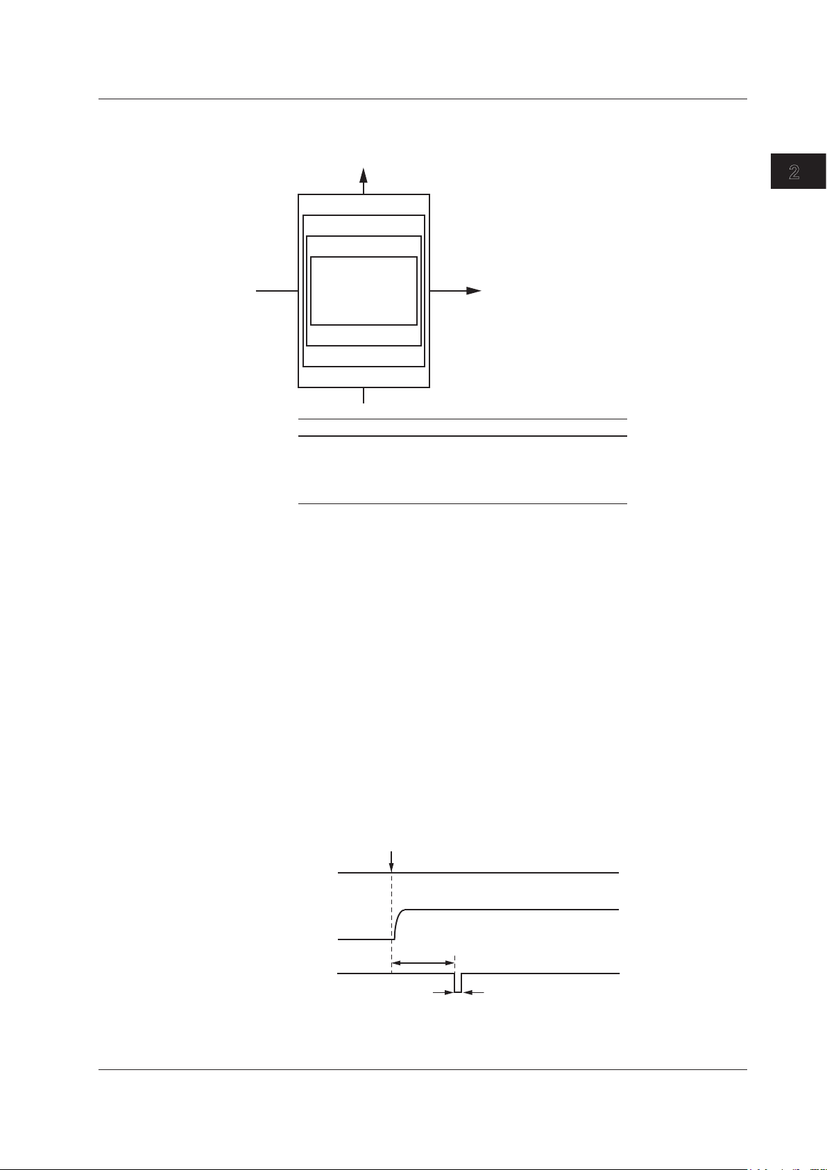
During DC Source Operation (When a program is not running)
The actual source level will change at the time the setting change is instructed from a
panel operation or communication command. The source change completion (Ready)
signal, which is a low-level pulse signal with a width of 10 μs, is generated 10 ms after
the source level changes. Additionally, the trigger busy (TrigBusy) signal, which indicates
the program execution status, remains at high level and does not change.
IM GS210-01EN
2-7
Page 29
RUN key
Trigger busy
(TrigBusy)
Source change
completion
(Ready)
Source level
Ti
Ti
Ti: Program interval time
10 ms
2.3 Source
2-8
IM GS210-01EN
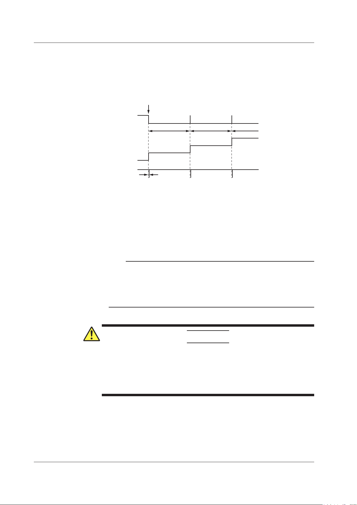
During Program Execution
When you execute a program, the trigger busy signal is set to low level, and the source
level changes. The source change completion (Ready) signal, which is a low-level pulse
signal, is generated 10 ms after the source level changes. When each program interval
time completes, the trigger busy signal is set to high level. The program proceeds from
step to step by repeating this pattern.
Output ON/OFF (See section 5.5 for the procedure)
There are two output modes: OFF or ON.
OFF: The output is disconnected, and the specified source level is not generated. In
this mode, program and measurement functions are disabled.
The output is connected, and the specified source level is generated. In this
ON:
mode, program and measurement functions are enabled.
Note
A mechanical relay operates when the GS200 switches between output on and output off. Note
the following points when using the GS200.
• It takes approximately 20 ms for the relay to stabilize.
• As the number of on/off operations increases, effects begin to appear such as the relay
taking longer to stabilize. Though dependent on the load, the electrical life of the relay is
around 100,000 operations.
DUT Protection Using Limiters (See section 5.4 for the procedure)
CAUTION
If a current source that exceeds the current limiter setting is connected in voltage
source mode; if a voltage source that exceeds the voltage limiter setting is
connected in current source mode; or if a load that exceeds the source range listed
above is connected, an abnormal load is detected, and the output is turned off (the
output trips). Do not connect these types of loads to the GS200. Doing so may
damage the instrument.
Voltage Limiter and Current Limiter
If a limiter is set, an additional limit can be placed within the source range. This limit can
prevent damage to the connected device due to overcurrent or overvoltage. In voltage
source mode, the current limiter is enabled. In current source mode, the voltage limiter is
enabled.
Page 30
I
V
Source voltage level
High limit value
Low limit value
Operating
range
I
V
High limit value
Low limit value
Operating
range
Source current level
2
1
2.3 Source
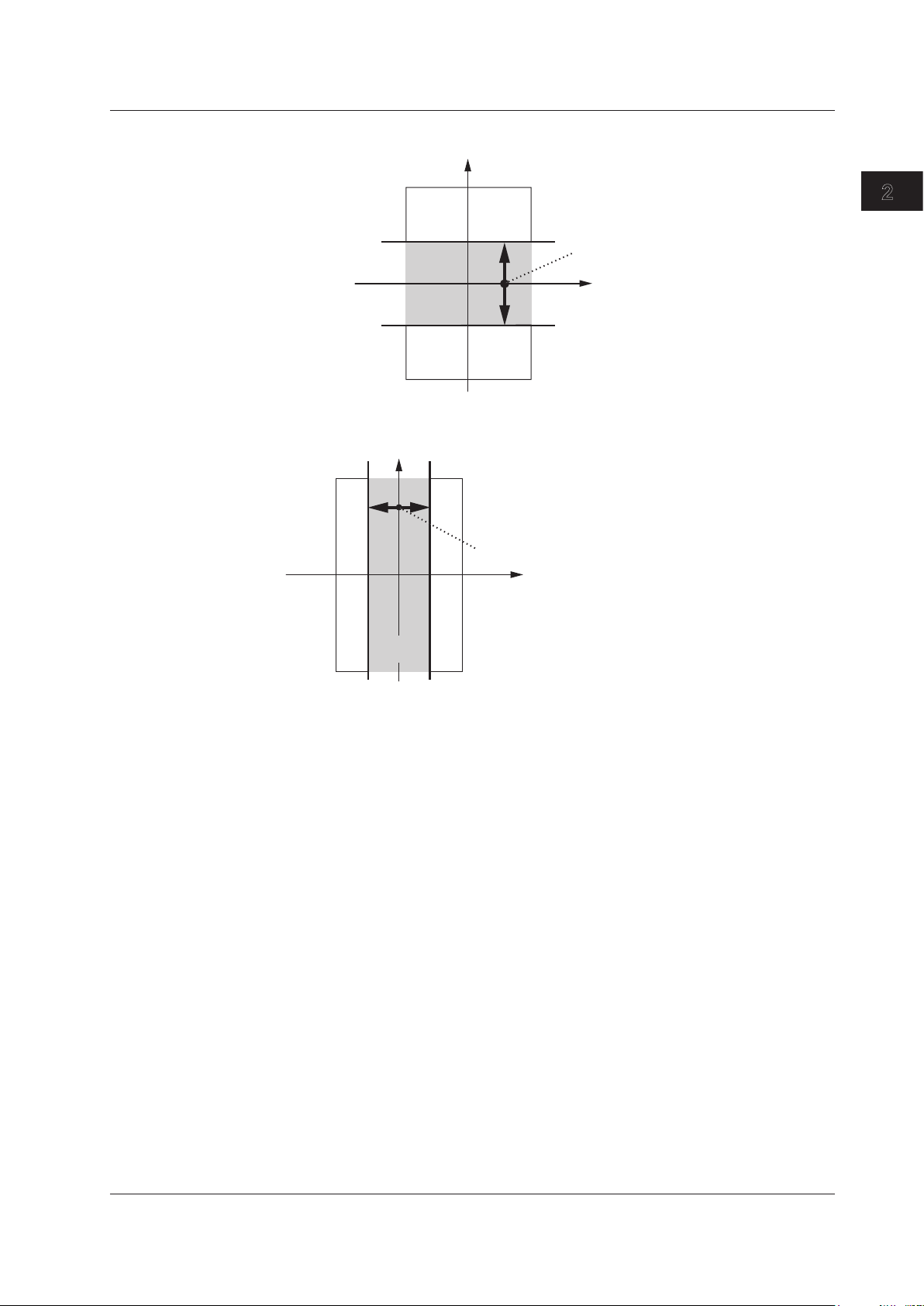
Limiter Operation in Voltage Source Mode
Features
Limiter Operation in Current Source Mode
A limiter has an operating range which is defined by a positive value and a negative
value in relation to 0. The positive value is the high limit. The negative value is the low
limit.
If the high limiter is activated, the high limiter indicator (H) is displayed. If the low limiter is
activated, the low limiter indicator (L) is displayed.
Tripping the Output
If the GS200’s output exceeds the high limiter or falls below the low limiter, the output
is automatically turned off. If this occurs, the error indicator illuminates, and the event is
written to the error log.
Local Sense and Remote Sense (See section 4.2 for the procedure)
Two wiring systems, 2W (two-terminal connection or local sense) and 4W (four-terminal
connection or remote sense) are available. In voltage source mode, when the current
flowing through the load becomes large, the voltage drop in the lead wire can no longer
be ignored. If this occurs, you can select the four-terminal connection and connect the
SENSE terminal near the DUT so that the voltage at the connected location is adjusted
to the specified voltage. This alleviates the effects from lead wire resistance, and the
desired voltage can be applied to the DUT.
IM GS210-01EN
2-9
Page 31

2.3 Source
2-10
IM GS210-01EN
Guard Terminal Feature (See section 4.3 for the procedure)
If the GS200 and the DUT are far apart or if the GS200 shares its power source with
electric motors, common mode noise may be superimposed on the power source signal
supplied to the DUT. If common mode noise is superimposed on the signal between the
GS200’s Hi and Lo terminals, the noise current enters the internal source circuit from
the output terminals and changes the generated signal. To reduce this effect, a shield
for the source circuit is connected to the guard terminal of the GS200. If you connect the
noise source to the guard terminal, the noise current passes through the guard and is
grounded, bypassing the internal source circuit. This reduces the amount of noise that
enters the circuit from the connected power source. Use the guard terminal when a large
amount of common mode noise is superimposed on the power source signal.
Page 32

2.4 Programs
1 V
4 V
2 V
1 V
5 V
7 V
Ti
Ti: Program interval time
Ti
Ti
Ti
Ti
Ti
Program slope time
Next step’s source level – current step’s source level
2
1
Program Feature (See section 6.1 for the procedure)
The program feature enables you generate the source data pattern that you specified
as a program in advance. Each step in the program is executed in order, and each step
has a fixed execution time. You can also set the slope time, so you can generate step
responses, ramp responses, and various waveforms such as triangular waveforms.
To create and load programs you can:
•
Create and edit programs from the GS200 screen.
•
Create programs on a PC, save them to the GS200’s internal memory (GS200ROM)
as program files in CSV format, and load them from the internal disk.
Source data that programs can contain:
• The source level.
•
The source range.
• The source function.
Programs can contain up to 10000 steps. If the number of steps exceeds 10000, only the
first 10000 steps are loaded.
Program Interval Time (See section 6.2 for the procedure)
The program interval time specifies the execution interval for each step in the program.
Features
Program Slope Time (See section 6.3 for the procedure)
The program slope time specifies the amount of time that the GS200 takes to linearly
change (increase or decrease) the current step’s source level to the next step’s source
level from the beginning of the step. The slope of this linear line is calculated as follows:
IM GS210-01EN
2-11
Page 33

Ts: Program slope time
Ti: Program interval time
* The TrigBusy signal’s state transitions shown here assume that the program
trigger is set to Norm.
Ti
Ti
Ts < Ti
Ti
Ti
Ts = 0
Ti
Ti
Ts > Ti
Ti
Ti
Ts = Ti
Ts
Ts
RUN key
TrigBusy
Ready
TrigBusy
Ready
RUN key
RUN key RUN key
2.4 Programs
2-12
IM GS210-01EN
When Ts is greater than Ti, the situation shown in the bottom right section of the figure
above occurs, so be sure to make Ts less than or equal to Ti.
Repeating Programs (See section 6.1 for the procedure)
If you specify to repeat programs, after the last step in a program finishes, the first step in
the program begins executing.
Program Triggers (See section 6.4 for the procedure)
Depending on the program trigger setting, there are the following two types of program
operation.
When Program Triggers Are Set to Normal (Norm)
You can use the RUN, STEP, and HOLD keys and external triggers to control the
program execution.
RUN key: Executes the program from step 1.
STEP
HOLD key: Pauses the program execution or resumes execution of a paused program.
The program interval time specifies the execution interval for each step in the program.
When Program Triggers Are Set to Measurement End (M.End; only on
models with the /MON option)
The program executes the source and measurement operations of each step in the
minimum time required. The RUN, STEP, and HOLD keys and external triggers are
disabled. Additionally, the program interval setting is ignored.
key: Executes only one program step.
Page 34

Program Files
1 V
4 V
2 V
1 V
5 V
7 V
1,10,V
4,10,V
2,10,V
1,10,V
5,10,V
7,10,V
Program file
Source level, source range, source function
Ti
Ti: Program interval time
Ti
Ti
Ti
Ti
Ti
2
1
2.4 Programs
You can use the USB storage feature (see page 2-22) to store programs in the
PROGRAM folder in the GS200’s non-volatile disk (GS200ROM).
Prgm01.csv and Prgm02.csv that are stored in the PROGRAM folder when the GS200
is sent from the factory or when you format its disk are program file samples. You can
check the contents of program files on the display.
Program File Contents (See section 6.5 for the procedure)
Program files are text files that have been created and edited in spreadsheet applications
or text editors. Each file contains multiple lines, and each line represents one step in the
program.
Features
Line
A line is a string of text that is delimited with line-feed codes (LF or CR+LF). Each line
defines the following items (from left to right).
•
The source level:
Defined with an integer or a real number. Examples: 1, 0.485,
–12E–3
• The source range:
Defined with an integer or a real number. Examples: The same
as the examples given above.
• The source function:
Defined with a character (V or I).
Make the program file a .CSV file by using a separator (choose either a comma or
a semicolon) to separate each item. You can also include white space (space or tab
characters) before and after each item.
You can omit the source range and source function. If any items are omitted, the same
item from the previous step is used. If the source function is not defined in the program’s
first step, the source function that the GS200 was using when the program file was
loaded is used. If the source range is not defined in the program’s first step, the source
range is set to the most appropriate range for the source level that is defined in the
program’s first step.
Comments
You can include comments in program files. A comment consists of any text between “//”
and a line-feed code or the end of the file. The GS200 ignores comments when it loads
program files.
IM GS210-01EN
2-13
Page 35

Ts: Program slope time
Ti: Program interval time
Ti
Ti
RUN key
TrigBusy
Ready
HOLD key STEP key
HOLD key
Ts Ts Ts Ts
Ti Ti
Executing Paused
Step
execution
Paused Executing
End
Step
completion
State
Key
0 V
1 V
2 V
3 V
The low pulse that indicates source change completion (Ready) is generated 10 ms after Ts elapses.
2.4 Programs
2-14
IM GS210-01EN
Executing Programs (See section 6.7 for the procedure)
Operations When the Program Trigger Is Set to Norm
You can use the RUN, STEP, and HOLD keys and external triggers to control the
program execution. The program interval time specifies the execution interval for each
step in the program.
When you press the HOLD or STEP key, the trigger busy (TrigBusy) and source change
completion (Ready) signals change as shown in the following example.
Program Setup Example
Step 1: 1 V
Step 2: 2 V
Step 3: 3 V
Program Conditions
•
Repeat mode is of
• Program interval time is 5 s.
• Program slope time is 3 s.
f.
HOLD and STEP
When you press the HOLD key to pause program execution, the paused step is said
to be in the “mid-execution” state. If you press the STEP key while the GS200 is in this
state, the current step that was in the mid-execution state is re-executed. When this step
completes, the GS200 pauses the program again. If, on the other hand, you press the
HOLD key while the GS200 is in this state, the GS200 continues program execution from
the point that it was paused in the step that was in the mid-execution state.
For example, assume that we have a program that begins at 0 V and ends at 10 V. Each
step specifies an increase of 1 V, and a step is executed each second. Now assume that
we execute the program and press HOLD when 4 V has been generated for only 0.5
seconds.
•
If the STEP
The GS200 does not generate 5 V as specified by the next step, but rather generates
4 V for 1 second as specified by the step that was in the mid-execution state, and then
pauses execution again. If you press the STEP key once more, 5 V is generated for 1
Key Is Pressed
second, and then the program execution is paused again.
Page 36

Ts: Program slope time
M.End
TrigBusy
Ready
Ts
M.End
Ts
The low pulse that indicates source change completion (Ready) is generated
10 ms after Ts elapses.
2.4 Programs
2
1
• If the HOLD Key Is Pressed
The GS200 generates 4 V for the remaining 0.5 seconds as specified by the step
that was in the mid-execution state, generates 5 V for 1 second, and then continues
executing the rest of the program.
Operations When the Program Trigger Is Set to M.End (/MON option)
When measurement completes, the GS200 proceeds to the next step in the program and
changes the source level. If you set the program trigger to measurement end (M.End),
and the measurement trigger to source change completion (Ready), the program
executes the source and measurement operations of each step in the minimum time
required.
The RUN, STEP, and HOLD keys and external triggers are disabled. Additionally, the
program interval setting is ignored.
Changes to the Control Signals
The trigger busy (TrigBusy) and source change completion (Ready) signals change as
shown in the following example.
Features
IM GS210-01EN
2-15
Page 37

2.5 Measurement (Monitoring feature; /MON
Measurement
trigger
Measurement
delay
Displays the measured value
Stores to the storage
memory
NULL
computation
Integration time
and software
processing time
Measurement
Zero reference
measurement
Integration time
and software
processing time
Only when the NULL computation
is turned on
2-16
IM GS210-01EN
option)
Measurement Function and Measurement Range
Measurement Function
In voltage source mode, the GS200 measures (monitors) current. In current source
mode, the GS200 measures (monitors) voltage.
Measurement Range
When Measuring Voltage
Range Measurement Range Resolution
30 V ±31.000 V 1 mV
When Measuring Current
Range Measurement Range Resolution
200 mA ±210.00 mA 10
Measurement ON/OFF (See section 7.1 for the procedure)
Measurement OFF (Off)
Measurement is not performed. Select this mode if you only intend to use the GS200
source features.
Measurement ON (On)
Measurement is performed. The measured value is displayed in the upper-left section of
the screen.
A
μ
Note
When you turn measurements on, noise may be superimposed on the source output depending
on the operation of the GS200 internal measurement circuit. To reduce noise in the source
output, turn measurements off.
Measurement Operation
Measurement operation refers to a sequence of measurements that is carried out as a
result of a measurement trigger. Measurement begins after a measurement trigger is
received and the specified measurement delay elapses. For information on triggers, see
section 2.6. For information on measurement delay, see the next page.
The overall process of the measurement operation is described in steps 1 to 3 below.
1.
Measurement
The GS200 performs the target measurement.
the sum of the integration time and the software processing time.
2. Zero Reference Measurement
The GS200 performs the zero reference measurement. The time required for the zero
erence measurement is the sum of the integration time and the software processing
ref
time.
3. NULL
The GS200 subtracts the NULL reference value from the mea
the difference the result. If NULL computation is OFF, nothing is performed.
The time required for measurement is
Computation (See the next page)
sured value and makes
Page 38

2.5 Measurement (Monitoring feature; /MON option)
2
1
Note
• If you change GS200 settings while measurements are being performed, those
measurements are invalid. The measured result display shows “-----,” and you cannot store
the results.
• Software processing time is less than 1 ms.
Measurement Delay (See section 7.3 for the procedure)
Measurement delay is the wait time from when a measurement trigger is applied to
when the measurement operation is carried out. You can adjust the timing between
the measurement trigger and the measurement operation by changing this setting. For
example, you can set the time needed for the DUT to stabilize after source change
completion to the measurement trigger, so that measurement is performed when the
DUT has stabilized.
Highly Accurate Measurement and High-Speed Measurement
Depending on the settings, the following measurement conditions enable you to perform
highly accurate measurements or high-speed measurements.
Local Sense and Remote Sense (See section 4.2 for the procedure)
Two wiring systems, 2W (two-terminal connection or local sense) and 4W (four-terminal
connection or remote sense) are available (see page 2-9). When the DUT allows a large
output current to flow, the voltage drops due to wire resistance. 4W is effective in this
kind of situation. In voltage source mode, you can minimize the effect of wire resistance
and measure the voltage that is applied to the DUT. In current source mode, you can
minimize the effect of wire resistance and measure the voltage that the DUT generates.
Features
Integration Time (See section 7.2 for the procedure)
An integrating A/D converter is used for measurements. If you set a long integration time,
the measurement takes longer, but the stability of the measured values increases.
Offset Calibration Feature
Zero Calibration (Manual Zero) Feature (See section 7.7 for the procedure)
If zero calibration is executed from the GS200’s operation menu, output is automatically
turned off, the zero reference is measured, and the zero reference is applied to
subsequent measured results. The zero point may change due to the passage of time,
the GS200 being in an environment where the temperature changes drastically, or due to
other factors. By executing zero calibration, the zero point is calibrated, and this enables
the GS200 to generate more accurate output.
NULL Computation (See section 7.6 for the procedure)
In NULL computation, the GS200 can display a difference from a given measured
value. When you turn NULL computation on, the next measured value is taken to be the
NULL value. For subsequent measured values, the measured results are obtained by
subtracting this NULL value.
Measured result = measured value – NULL
value
IM GS210-01EN
2-17
Page 39

Maximum – minimum
Mean value
Standard deviation
Minimum value
Maximum value
Storage count
Timestamp
Source function
Source level
Measurement function
Measured value
2.5 Measurement (Monitoring feature; /MON option)
2-18
IM GS210-01EN
Store/Recall (Statistical Computation Value Display)
Storing Measured Results (See section 7.8 for the procedure)
This feature enables you to save the specified number of measured results to storage
memory. You can specify a storage count in the range of 1 to 10000. If the storage
operation is aborted before the specified storage count is met, the measured results
up to that point are stored. If the stored result file generation feature is turned on, the
stored results are saved to a result file (Result.csv) in the built-in GS200RAM (see
“USB Storage Feature” on page 2-25) when storage completes. If the stored result file
generation feature is off, the stored results are not saved to a file. In this case, use the
communication feature to read the measured results.
Performing Statistical Computations on Measured Values (Recall; see
section 7.9 for the procedure)
The statistical computation results of the most recent measured values in the storage
memory can be displayed. The statistical computation parameters are the storage count,
maximum value, minimum value, maximum value – minimum value, mean value, and
standard deviation.
Result File (See section 7.8 for the procedure)
The result file (Result.csv) contains the measured results that have been stored in
storage memory. It is generated by the stored result file generation feature and is saved
to the internal GS200RAM. Each entry in the result file contains the elapsed time from
the start of the first measurement operation (a timestamp), the source function, the
measurement function, the source level, and the measured value.
Example of a Result File
The name of the most recent result file is always Result.csv. Up to 33 result files are
stored on the GS200RAM. Less files are stored if their size exceeds the memory limit
(16 MB). When the storage operation is repeated, the names of existing result files are
changed automatically. For example, if two storage operations are completed, the most
recent file will be Result.csv, and the previous result file will be changed to Result.01.csv.
If the storage operation is repeated further, the name of a result file will be changed as
follows: Result.csv, Result.01.csv, Result.02.csv, Result.03.csv, and so on. If the number
of result files exceeds 33, the files are deleted in order from the oldest file. However,
if deleting the oldest file does not clear sufficient space to make room in the internal
GS200RAM for the new result file, multiple result files may be deleted.
Page 40

Newest result file
Third newest result file
Second newest result file
Result.csv
Result.01.csv
Result.csv
Result.01.csv
Result.csv
Result.02.csv
Newest result file
The file names are automatically
updated.
The file names are automatically
updated.
When the first storage
operation completes
When the second storage
operation completes
When the third storage
operation completes
Past
Current
Result files stored in the GS200RAM
2
1
2.5 Measurement (Monitoring feature; /MON option)
GS200RAM Containing Result Files
Features
Result File Numbering
Reading the Storage Result through Communications (See section 7.9 for
the procedure)
You can use the communication feature to read the storage result directly. You can set
the format used to read the data to ASCII or binary.
In addition, statistical computation values can also be read using the communication
feature.
IM GS210-01EN
2-19
Page 41

2.6 Triggering
2-20
IM GS210-01EN
Overview
The GS200 uses program triggers, which are used to start and pause programs, and
measurement triggers, which are used to start measurements.
Program Triggers (See section 6.4 for the procedure)
This trigger is used to drive programs (see section 2.4). On models with the monitoring
(/MON) option, you can select the normal (Norm) or measurement end (M.End) trigger
source. On models without the monitoring (/MON) option, only the normal (Norm) trigger
source is available.
Normal (Norm)
You can use the following four triggers to execute programs.
• RUN key
Press this key to begin program execution from step 1. The program proceeds one
step each time the program interval time elapses.
• STEP
Press this key to execute only the current step. When the program interval time
• HOLD key
Press this key to pause the program that is running. If you pre
• External triggers (External)
The falling edge of a signal applied to TRIG IN of the input term
key
elapses, program execution stops.
ss this key when a
program is paused, program execution begins again from the exact point in the step
that it was previously paused.
inal for synchronous
operation (SYNC IN, see section 8.2) or TRIG IN of the BNC I/O terminal (see section
8.1) on the rear panel is used as a trigger. This trigger performs the same function as
the STEP key on the front panel.
Measurement End (M.End; only on models with the /MON option)
When the trigger source is set to measurement end, program execution proceeds from
one step to the next as soon as the current step’s measurement completes, regardless of
the program interval time. You can execute programs at their optimal speed, but program
execution always requires the specified integration time (measurement time). However,
you have to set the measurement trigger to source change completion (Ready).
When the program trigger is M.End, the RUN, STEP, and HOLD keys are disabled, and
the program interval time is ignored.
Page 42

2.6 Triggering
2
1
Measurement Triggers (/MON option; see section 7.4 for the procedure)
This trigger is used to start a measurement operation (see section 2.5). Select any of the
following trigger sources.
• Measurement timer (
can set the constant period timer to a period from 0.1 seconds to 3600.0 seconds.
You
The timer is reset when you turn the output on.
• Measurement completion (immediate;
The end of one measurement triggers the beginning of the next measurement.
used in situations such as when you need to repeat measurements at high speeds.
• Source change completion (
This is generated 10 ms after the source level is changed.
• Communication commands (Comm)
You can use the communication command
Timer)
Ready)
Immed)
"*TRG"
to start measurements.
Features
This is
IM GS210-01EN
2-21
Page 43

Meas Trig
Meas Busy
MEASURE
PROGRAM
TrigIn
TrigOut
ProgramTrig
TrigBusy
P.Interval
External
Step
M.End
Immed
Timer
Ready
Meas.Timer
P.Interval Timer
STEP
HOLD
RUN
Ready
Comm
“*TRG”
2.6 Triggering
2-22
IM GS210-01EN
Trigger Block Diagram
Page 44

Trigger Output (See sections 8.1 and 8.2 for the procedures)
2
1
The GS200 can output the program trigger signal from the SYNC OUT terminal (I/O
terminals for synchronous operation) or the BNC output terminal to the subsequent
GS200s that are connected.
TrigOut
TrigOut transmits the trigger busy signal.
•
When program triggers are set to normal (Norm)
When a program trigger is generated, this signal is set to low l
interval time elapses, this signal is set to high level.
• When program triggers are set to measurement end (M.End)
When a program trigger is generated, this signal is set to low l
program interval time, this signal is immediately set back to high level.
Trigger Hold
You can pause program execution by pressing the HOLD key on the front panel or by
transmitting the communication command “:PROGram:HOLD” or “:PROGram:PAUSe.”To
resume program execution, press the HOLD key again, or transmit the communication
command “:PROGram:HOLD” or “:PROGram:CONTinue.”
Sampling Error
If one of the following invalid triggers occurs, the sampling error indicator on the front
panel illuminates.
• A
new measurement trigger occurred while a measurement operation was in progress.
• The RUN or STEP key was pressed or an external trigger signal was received while a
program was running.
2.6 Triggering
Features
evel. When the program
evel. Regardless of the
Note
If sampling errors occur, the trigger generation timing may be too fast. If the sampling error
indicator illuminates, check settings such as the selected trigger source and timer period.
IM GS210-01EN
2-23
Page 45

2.7 Synchronization
2-24
IM GS210-01EN
Synchronization
You can connect multiple GS200s and synchronize switching of the output between on
and off and their program execution.
External I/O
There are two types of external I/O terminals on the GS200: the I/O terminals for
synchronous operation (SYNC In/OUT) and the BNC I/O terminals (IN and OUT).
RJ-11 Connector (I/O terminals for synchronous operation; SYNC IN/OUT;
see section 8.2 for the procedure)
By using the I/O terminals for synchronous operation (SYNC IN/OUT) on the rear panel,
you can synchronize the operation of multiple connected GS200s. Use synchronous
operation cables (758960) that are sold separately to connect the GS200s in a daisy
chain. The first unit is connected to the second unit, the second unit is connected to the
third unit, and so on. You can synchronize the operation of program triggers and the
output state (output on and off).
BNC I/O (IN and OUT; see section 8.1 for the procedure)
You can use the BNC connectors at the top of the rear panel to apply and transmit any of
the following signals as external signals. You can use these connectors for synchronous
operation and other purposes.
•
Output state (output on and of
• Program trigger I/O
• Source change completion (Ready) output
f) I/O
Page 46

2.8 Other Features
2
1
USB Storage Feature (See section 4.4 for the procedure)
The GS200’s internal memory consists of a 4 MB non-volatile disk (GS200ROM) and
a 16 MB volatile disk (GS200RAM). If you use a USB cable to connect the GS200 to
a PC, you can access these disks from the PC as removable disks. You can store the
program files that you have created using a general-purpose spreadsheet application to
the GS200ROM non-volatile disk simply by dragging the files from the location they are
stored on the PC.
The volatile disk (GS200RAM) stores measured results. If you load the measured result
file on your PC, you can use a general-purpose spreadsheet application to edit the data
or display the data as graphs. The system file that is used to update the GS200 system
is also stored on this disk.
Features
Non-Volatile Disk (GS200ROM)
The GS200ROM is a non-volatile disk. Even if you turn the GS200 off, the contents of
this disk are not lost. Two folders are stored on this disk: PROGRAM and SETUP.
IM GS210-01EN
2-25
Page 47

2.8 Other Features
2-26
IM GS210-01EN
PROGRAM
This folder contains all the program output pattern files. All the files in this folder can be
used as program files.
When the GS200 is sent from the factory, two sample program files are stored in this
folder. These sample program files are also created when you format the disk.
SETUP
This folder contains all the panel setup files. Any of the files in this folder can be selected
as a setup file.
When the GS200 is sent from the factory, a sample setup file is stored in this folder. This
sample setup file is also created when you format the disk.
Volatile Disk (GS200RAM)
The GS200RAM is a volatile disk. When you turn the GS200 on, this disk is automatically
formatted. During storage, the result file (Result.csv) is created on this disk.
This disk is normally used to transfer files that the GS200 generates to your PC.
However, a system file is transferred from your PC to this disk when you update the
system firmware. For details, see section 14.5, “Updating the System Firmware.”
Note
You can create files and folders on the GS200RAM, but be sure that the disk does not become
full. The data on this disk is lost when the GS200 is turned off.
Formatting the Disk
You can format the disk if you want to reset the GS200ROM to the factory default
conditions, if the non-volatile or volatile disk cannot be detected by your PC, or if you
believe the data on the disk is corrupt.
USB Communication (USB-TMC command control; see chapter 10 for the procedures)
The GS200 has a USB2.0 device interface. This interface allows access to the USB
storage feature as well as allows command control from a VISA (Virtual Instrument
Software Architecture) library using a VISA USB-TMC device driver as defined by the VXI
Plug&Play System Alliance.
Page 48

2.8 Other Features
2
1
Ethernet Communications (/C10 option; see chapter 11 for the procedures)
The GS200 has a LAN interface with auto switching between 10 Mbps and 100 Mbps.
You can assign a static IP address or obtain an address dynamically from a DHCP
server. The following four features are available.
Command Control Using VXI-11
The GS200 has an Ethernet VXI-11 device driver. This allows command control from a
VISA library.
Panel Control Using a Browser (see section 11.5 for the procedure)
The GS200 has a Web server feature. This allows you to display the front panel image
of the GS200 on a PC’s Web browser and remotely control the GS200 from the Web
browser.
File Transfer with FTP Clients
Up to five clients can establish FTP connections by way of the anonymous FTP server
function. The non-volatile disk (GS200ROM) and volatile disk (GS200RAM) can
be handled as a PC file server. Files such as program files can be transferred, and
measured result data can be loaded onto a PC through the use of the FTP protocol.
For information on the GS200ROM and GS200RAM, see “USB Storage Feature,” on
page 2-25.
Command Control Using Port 7655
The GS200 has a command mnemonic stream parsing server that can connect up to five
clients. The terminator (CR, LF, or CR+LF) can be specified.
Features
Because each server feature is independent, you can for example, control the GS200
using commands while it is transferring files using FTP.
GP-IB Communications (See chapter 12 for the procedures)
The GS200 has an interface that is used to control the GS200 using commands. You
can specify the same settings as you would using the front panel keys of the GS200 and
output setup data and measured data. Because the command control of the GS200 is
mutually independent, other communication features can be used while you are using
GP-IB to control the GS200.
Saving, Loading, and Deleting Setup Data (See section 9.2 for the procedure)
The current settings can be saved to a setup file (Setup01.txt to Setup04.txt) on the nonvolatile disk (GS200ROM). The saved setup data can be loaded to restore the settings.
The setup file is a text file that contains communication commands. This file can be
edited later on your PC.
For information on the GS200ROM and GS200RAM, see “USB Storage Feature,” on
page 2-25.
Selecting the Settings Applied at Power-On (See section 9.3 for the procedure)
The GS200 settings at power-on can be changed from the default settings to the settings
selected by the user.
If the selected file is deleted or renamed, the GS200 will start with its default settings.
IM GS210-01EN
2-27
Page 49

Chapter 3
3
2
1
Instrument Preparation and Common Operation
3.1 Handling Precautions
Read the Safety Precautions
Safety Precautions
If you are using the GS200 for the first time, make sure to read “Safety Precautions,” on
pages v and vi.
Do Not Remove the Case
Do not remove the case from the instrument. Some sections inside the instrument have
high voltages that are extremely dangerous. For internal inspection and adjustment,
contact your nearest YOKOGAWA dealer.
Unplug If Abnormal Behavior Occurs
If you notice smoke or unusual odors coming from the instrument, immediately turn off
the power and unplug the power cord. If these symptoms occur, contact your nearest
YOKOGAWA dealer.
Correct the Problem If Output Is Forcibly Turned Off
If the GS200 detects an internal circuit error due to an excessive external input or
electrical oscillation, the output is forcibly turned off, the ERROR indicator illuminates,
and the error message “An abnormal load is connected” is displayed. If this happens,
remove the cause of the problem, such as the external load, and turn the output on
again. If the output still turns off after you have corrected the problem, the GS200 may be
malfunctioning. Contact your nearest YOKOGAWA dealer. Note that even if the GS200 is
returned to normal, the error display remains until you manually clear it (see section 9.6,
“Error Log Display”) or use communication commands to read the error information.
s
Instrument Preparation and Common Operations
Turn the Power Switch Off If Overheat is Detected
If the GS200 detects an overheat condition such as when the inlet or vent holes for the
cooling fan are obstructed or the fan is stopped, the GS200 forcibly turns the output off,
displays an “Abnormal Temperature” warning, and produces intermittent beeps. If this
happens, immediately turn the power switch off. Check that there is adequate space
around the GS200, and check for and remove any foreign objects that are caught in the
cooling fan on the rear panel. If the same warning appears when you turn the power
switch on after waiting a sufficient amount of time, the GS200 may be malfunctioning.
Contact your nearest YOKOGAWA dealer.
Handle the Power Cord with Care
Nothing should be placed on top of the power cord. The power cord should also be kept
away from any heat sources. When unplugging the power cord from the outlet, never
pull by the cord itself. Be sure to hold and pull by the plug. If the power cord is damaged,
purchase a replacement with the same part number as the one indicated on page iii.
IM GS210-01EN
3-1
Page 50

3.1 Handling Precautions
3-2
IM GS210-01EN
General Handling Precautions
Do Not Place Objects on Top of the Instrument
Never place objects such as those that contain water on top of the instrument. Doing so
may damage the instrument.
Do Not Apply Shock or Vibration
Do not apply shock or vibration. Doing so may damage the instrument. In addition,
applying shock to the input/output terminal or the connected cables can cause electrical
noise to enter or be generated from the instrument.
Keep Electrically Charged Objects Away from the Instrument
Keep electrically charged objects away from the input and output connectors. They may
damage the internal circuitry.
During Extended Periods of Non-Use
Turn off the power switch, and remove the power cord from the outlet.
When Carrying the Instrument
First, remove the power cord and connection cables. The instrument weighs
approximately 5 kg. To carry the instrument, use the handle as shown in the figure below,
and move the instrument carefully.
When Cleaning the Instrument
When cleaning the case or the operation panel, turn off the power switch, and remove
the power cord from the outlet. Then, wipe the instrument lightly with a clean dry cloth.
Do not use volatile chemicals such as benzene or thinner for cleaning, as they may lead
to discoloration or deformation.
Page 51

3.2 Installation
Rotary axis
Handle Stop Positions (We recommend that you use positions 1, 3, 5, and 8. Do
not place a heavy load on the GS200 when the handle is in stop position 2 or 4.)
Pull this out approximately
2 mm to 3 mm, and rotate
the handle.
1
2
3
4
5
6
7
8
3
1
3
2
1
Installation Orientation
WARNING
• To prevent fire, never use the instrument with the rear panel facing down. There
are vent holes for the cooling fan on the rear panel. Placing the instrument with
the rear panel facing down may cause a fire when the instrument malfunctions.
•
This instrument is designed to be used indoors. Do not install or use it outdoors.
Install the instrument so that you can immediately remove the power cord if an
•
abnormal or dangerous condition occurs.
CAUTION
If you block the inlet or outlet holes on the GS200, the GS200 will become hot and
may break down.
• Place the instrument in a horizontal position as shown in the left section of the figure
below or in an inclined position using the handle as shown in the center section of the
figure below
• To use the handle as a stand to tile the instrument, first check
in place, and then position the instrument. To rotate the handle, first pull the handle’s
rotary axis out approximately 2 mm to 3 mm on both the left and right sides of the
instrument, and then rotate it to one of its stop positions.
Instrument Preparation and Common Operations
.
that the handle is fixed
IM GS210-01EN
WARNING
• When adjusting the handle, be careful not to injure your hand with the edges of
the handle.
• When you put away the handle, be careful not to get your hand caught between
the handle or movable legs and the instrument.
3-3
Page 52

10 cm or
more
5 cm or more5 cm or more
10 cm or more
Provide adequate space around the GS200.
3.2 Installation
3-4
IM GS210-01EN
Installation Location
• Handling the handle without firmly supporting the instrument can be dangerous.
Please take the following precautions.
• Only handle the handle when the instrument is on a stable s
urface.
• Do not handle the handle when the instrument is tilted.
• Do not place the instrument in any position other than those shown in the above
figures.
Install the instrument in a place that meets the following conditions.
Ambient Temperature and Humidity
Use the instrument in the following environment.
• Ambient temperature: 5°C to 40°C
However, when you want to generate output with high accuracy, operate the
instrument in the 23 °C ± 5°C temperature range.
• Ambient humidity: 20% RH to 80% RH
No condensation should be present.
Note
Condensation may form when moving the GS200 from a low temperature or humidity
environment to a high temperature or humidity environment, or when there is a sudden change
in temperature. In these kinds of circumstances, wait for at least an hour before using the
GS200, to acclimate it to the surrounding environment.
Flat and Even Location
Place the instrument on a flat, even surface. Do not place the instrument on an unstable
or sloped surface.
Well-Ventilated Location
There are inlet holes on the bottom side of the instrument. In addition, there are vent
holes for the cooling fan on the rear panel. To prevent internal overheating, allow for
enough space around the instrument (see the figure below), and do not block the inlet
and vent holes.
Page 53

Storage Location
3
2
1
3.2 Installation
Do Not Install the Instrument in the Following Places
• Outdoors
• In direct sunlight or near sources of heat
• Where the instrument is exposed to water or other liquids
• Where an excessive amount of soot, steam, dust, or corrosive gas is present
• Near sources of strong magnetic fields
• Near high-voltage equipment or power lines
• In an environment that is subject to large levels of mechanical vibration
• On an unstable surface
When storing the instrument, avoid the following places.
• Where the relative humidity is 80% or higher
• In direct sunlight
• Where the temperature is 60°C or higher
• Near a strong source of heat or moisture
• Where the level of mechanical vibration is high
• Where there are corrosive or explosive gasses
• Where an excessive amount of soot, dust, salt, or iron is present
• Where water, oil, or chemicals may splash
We recommend that the instrument be stored in an environment where the temperature
is between 5°C and 40°C and the relative humidity is between 20% RH and 80% RH.
Instrument Preparation and Common Operations
Rack Mount
To mount the instrument in a rack, use the separately sold rack mount kit. For the
procedure to rack mount the GS200, see the instructions that are included with the rack
mount kit.
Name Model Note
Rack mount kit 751533-E2 For EIA single mount
Rack mount kit 751534-E2 For EIA dual mount
Rack mount kit 751533-J2 For JIS single mount
Rack mount kit 751534-J2 For JIS dual mount
IM GS210-01EN
3-5
Page 54

3.3 Connecting the Power Supply
Three-prong outlet
Power cord
(standard accessory)
3-6
IM GS210-01EN
Before Connecting the Power Supply
To prevent electric shock and damage to the instrument, follow the warnings below.
WARNING
• Before connecting the power cord, ensure that the source voltage matches the
rated supply voltage of the instrument and that it is within the maximum rated
voltage of the provided power cord.
•
Connect the power cord after checking that the power switch o
turned OFF.
o prevent electric shock or fire, be sure to use the power cord for the instrument
• T
that is supplied by YOKOGAWA.
• Make sure to connect protective earth grounding to prevent el
Connect the power cord to a three-prong power outlet with a protective earth
terminal.
•
Do not use an extension cord without protective earth ground. The protective
features of the instrument will be rendered ineffective.
•
Use an
connect the protective grounding. If such an AC outlet is unavailable and
protective grounding cannot be furnished, do not use the instrument.
AC outlet that complies with the power cord provided and securely
f the instrument is
ectric shock.
Connecting the Power Cord
Check that the instrument’s power switch is off.
1.
Connect the instrument’s power cord to the power inlet on the rear panel.
2.
Connect the other end of the cord to an outlet that meets the conditions below.
3.
The AC outlet must be of a three-prong type with a protective earth ground
terminal.
Item Specifications
Suffix Code -1 -4 -7
Rated power supply voltage 100 VAC 120 VAC 230 VAC
Permitted power supply voltage range
Rated power supply frequency 50/60 Hz
Permitted power supply 48 Hz to 63 Hz
frequency range
Maximum power consumption Approx. 80 V
* The supply voltage that the GS200 can use differs depending on its suffix code. Before you use the
instrument, check that the voltage supplied to it is less than or equal to the maximum rated voltage of
the power cord provided with it (see page iii for the maximum voltage rating).
90 VAC to 110 VAC 108 VAC to 132 VAC 207 VAC to 253 VAC
A
Page 55

3.4 Turning the Power Switch On and Off
Off On
3
2
1
Before Turning On the Power, Check That:
• The instrument is installed properly (see section 3.2, “Installation”).
• The power cord is connected properly (see section 3.3, “Connecting the Power
Supply”).
Location of the Power Switch and On/Off Operation
The power switch is located in the lower left of the front panel. The power switch is a
push button. Press the button once to turn the instrument on, and press it again to turn
the instrument off.
Operations Performed When the Power Is Turned On
When the power switch is turned on, the GS200 logo appears on the screen, and a selftest starts automatically. If the test completes successfully, the GS200 is configured
according to the setup file selected in section 9.3, “Selecting the Settings Applied at
Power-On.” Check that the GS200 has started normally before you use it.
Instrument Preparation and Common Operations
Note
• Wait at least 5 seconds after you turn the GS200 off before you turn it back on.
When the Power-on Operation Does Not Finish Normally
Turn off the power switch, and check the following items.
• The power cord is securely connected.
• The voltage supplied from the power outlet is correct (see section 3.3).
• You can initialize the settings of the GS210 (see section 9.1).
If, after checking these items, the GS200 still fails to start when you turn the power switch
on, it may be malfunctioning. Contact your nearest YOKOGAWA dealer for repairs.
To Generate Accurate Output and Make Accurate Measurements
With the GS200 installed in a location that complies with the guidelines given in section 3.2,
allow the instrument to warm up for at least 60 minutes after the power switch is turned
on.
Turn the output off during warm-up. After the warm-up time elapses, turn the output on.
Operations Performed When the Power Is Turned Off
The setup data and measured results immediately before the power switch is turned off
are not retained. The same is true when the power cord is disconnected from the outlet.
We recommend that you save important setup data to the SETUP folder on the nonvolatile disk (GS200ROM). See sections 2.8, “USB Storage Feature” and 9.2.
Note
• If you turn the power off while output is on, the GS200 may produce a momentary beeping
sound, but this sound does not indicate an error.
IM GS210-01EN
3-7
Page 56

3.5 Wiring Precautions
Measure against noise when handling minute currents
GS200
OUTPUT Hi
OUTPUT Lo
DUT
Shield the lead wire of the high end
at ground potential.
3-8
IM GS210-01EN
WARNING
• Be sure to turn the GS200 output off before you connect the device that you are
generating output for.
• Do not connect a voltage source in voltage source mode or a
current source mode. An incorrect connection may damage the GS200.
• Do not connect a load that exceeds ±32 V or ±200 mA
and OUTPUT Lo terminals or across the SENSE Hi and SENSE Lo terminals.
• The maximum allowable voltage between the case and each t
Vpeak. Applying a voltage that exceeds this value may damage the GS200.
• Keep the voltage that is generated across OUTPUT
across OUTPUT Lo and SENSE Lo to less than or equal to ±0.5 Vpeak.
• When making a four-terminal connection, be careful that the c
the SENSE terminals does not get cut. If the voltage is not sensed correctly,
abnormal voltage may be generated across the OUTPUT Hi and OUTPUT Lo
terminals.
•
When making a two-terminal connection, use the OUTPUT
SENSE terminals are used, the current flows through the SENSE line. This
prohibits the GS200 from generating correct output and can damage the GS200.
current source in
across the OUTPUT Hi
erminal is ±250
Hi and SENSE Hi and
onnection to
terminals. If the
CAUTION
• Use conducting wires that have adequate margins of withstand voltage and
current capacity with respect to the voltage or current to be used.
• T
o prevent oscillations due to stray capacitance and lead inductance, use
twisted-pair lead wires to connect to the OUTPUT Hi and OUTPUT Lo terminals.
Likewise, use twisted-pair lead wires to connect to the SENSE Hi and SENSE Lo
terminals. In particular, wire the lead wires short in the case of a high-capacity
load in a four-terminal connection in voltage source mode.
Note
Susceptibility to the effects of noise increases when sourcing or measuring minute currents.
Take measures such as using shielded wires. Grounding shielded wires is an effective measure
to reduce the effect of noise.
Page 57

3.6 Wiring the GS211 Rear Panel Terminal Plug
Screw (2)
Screw used to fix the cable in place
Cable
SENSE
Hi
SENSE
Lo
OUTPUT
Lo
G
OUTPUT
Hi
Terminal plug pinout
3
2
1
Follow the procedure below to wire the rear panel terminal plug on a GS211, which has
rear panel output terminals. To prevent electric shock and damage to the instrument,
follow the warnings given in section 3.5, “Wiring Precautions.”
Unscrew the screws on the left and right of the terminal plug, and remove the
1.
terminal plug from the GS211.
Loosen the screws on the top of the terminal plug (these screws are used to fix
2.
cables in place), and insert stripped cables into the holes.
Instrument Preparation and Common Operations
• Length of stripped cable: 7 mm
• Rated connecting capacity
Single wire: 0.2 mm
Twisted wire: 0.2 mm2 to 2.5 mm
AWG: 24 to 12
Tighten the screws to fix the cables in place (screw tightening torque: 0.5 N•m to 0.6
3.
N•m).
Tighten the screws on the left and right of the terminal plug to attach it to the
4.
GS211 (screw tightening torque: 0.2 N•m to 0.3 N•m).
IM GS210-01EN
2
to 2.5 mm
2
2
3-9
Page 58

3.7 Setting the Date, Time, and the Time Difference
3-10
IM GS210-01EN
from GMT (Greenwich Mean Time)
Procedure
Press UTILITY to display the following menu.
1.
Setting the Date and Time
Press the Sys Config soft key to display the following menu.
2.
Press the Adjust Time soft key.
3.
Press the Clock soft key to display the date/time setup screen.
4.
Press the Edit soft key.
5.
6.
7.
8.
Synchronizing the Clock
9.
Press a soft key from Year to Second that corresponds to the setting that you
want to set.
In up/down key mode, press the and keys to set the date and time. In
keypad mode, press NUM LOCK +
4.1).
Press the Set soft key to set the value.
Press the Adjust Zero soft key to synchronize the clock by resetting the seconds
to zero.
If the seconds value is greater than or equal to 30 seconds, the minutes value increases by
1 minute, and the seconds value is set to 0.
or to set the date and time (see section
Page 59

3.7 Setting the Date, Time, and the Time Difference from GMT (Greenwich Mean Time)
3
2
1
Setting the Time Difference from GMT (Greenwich Mean Time)
Press the Time Zone soft key.
4.
Explanation
Setting the Date and Time
• Date (Year/Month/Day)
The year is displayed according to the Gregorian calendar.
• Time (Hour/Minute/Second)
The hour can be set to a value from 0 to 23.
Press the Edit soft key.
5.
Press the Hour or Minute soft key to set the corresponding setting.
6.
In up/down key mode, press the and keys to set the date and time. In
7.
keypad mode, press NUM LOCK +
Press the Set soft key to set the value.
8.
or to set the date and time.
Instrument Preparation and Common Operations
Note
• The date and time settings are backed up with the internal lithium battery when the power is
turned off.
• The instrument has leap-year information.
Setting the Time Difference from GMT (Greenwich Mean Time)
Set the time difference in the range of –12 hours 00 minutes to 13 hours 00 minutes.
For example, Japan standard time is ahead of GMT by 9 hours. In this case, set Hour to
9 and Minute to 00.
Checking the Standard Time
Using one of the methods below, check the standard time of the region where you are
using the GS200.
• Check the date and time setting on your PC.
•
Check the website at the following URL:http://www.worldtimeserver.com/
Note
The GS200 does not support Daylight Saving Time. To set the time to Daylight Saving Time,
reset the time difference from Greenwich Mean Time.
<<Corresponding Command Mnemonic>>
:SYSTem:CLOCk:DATE
:SYSTem:CLOCk:TIME
:SYSTem:CLOCk:TZONe
:SYSTem:CLOCk:ADJust
<character string>
<character string>
<character string>
IM GS210-01EN
3-11
Page 60

3
2
1
4
Soft keys
GS200
DC VOLTAGE/CURRENT SOURCE
SAMPLE
ERROR
REPEAT
STORE
REMOTE
ERROR
LOCAL
ESC
POWER
NUM
LOCK
1 2 3 4 5BSRANGE
6 7 8 9 0
UTILITY
SETUP
LIMIT
MEASURE
PROGRAM
END
DEL
HOLD
STEP
RUN
PROGRAM
OUTPUT
V
mV
mA
SRQ
ENTER
SENSE OUTPUT
32V
MAX
0.5V
MAX
32V
200mA
MAX
Hi
Lo
42V
10mA
PEAK
G
G TERM 250 V PEAK TO
Increases the corresponding digit
Press the +/– key to change the value’s sign.
Decreases the corresponding digit
The NUM LOCK key is off in up/down key mode.
NUM
LOCK
1 2 3 4 5
BS
6 7 8 9 0
Press the +/– key to change the value’s sign.
The NUM LOCK key illuminates in keypad mode.
1
2
3
4
5
Deletes one character
6
7
8
9
0
. (decimal point)
NUM
LOCK
1 2 3 4 5
BS
6 7 8 9 0
Chapter 4 Common Settings
4.1 Basic Key Operations and How to Enter Values
Basic Key Operations
Setting Keys
Press a setting key such as UTILITY or MEASURE to display a soft key menu at the
bottom of the screen.
Soft Keys
Press a soft key to make a choice on the soft key menu or to execute an operation.
Common Settings
How to Enter Values
There are two modes for entering values: up/down key mode and keypad mode.
Entering Values in Up/Down Key Mode
Entering Values in Keypad Mode
Press the and keys below each digit that is shown on the display to enter
1.
the value.
Press NUM LOCK. The NUM LOCK key illuminates.
1.
Press the and keys below the display to enter numbers 0 to 9 and the
2.
period.
IM GS210-01EN
4-1
Page 61

This part of the display blinks.
B
A
C
4.1 Basic Key Operations and How to Enter Values
4-2
IM GS210-01EN
In keypad mode, the value that you are entering blinks.
Example: Entering “4.5”
Press ENTER to enter the value that you have specified.
3.
How to Operate Setup Menus
Press a key to display a corresponding setup menu.
1.
Press a soft key corresponding to an item.
2.
A: The selected setting switches each time you press the soft key. The currently selected
setting is underlined.
B:
A numeric setting screen appears when you press the soft key. Enter the value in
up/down key mode or keypad mode.
A selection menu appears when you press the soft key. Press the soft key that
C:
corresponds to the selection you want to make.
How to Clear Setup Menus
Press ESC (LOCAL) to clear the setup menu. If the menu that is shown is under multiple
menu levels, press ESC (LOCAL) to move up a level in the menu hierarchy.
Note
Procedures in this manual do not include steps for clearing the setup menu.
Page 62

3
2
1
4
4.2 Selecting the Wiring System (Remote Sense or Local Sense)
Procedure
Press UTILITY to display the following menu.
1.
Explanation
There are two methods for connecting the GS200: 2W and 4W.
2W: Two-terminal connection (local sense)
4W:
The connection diagrams are given on the next page.
WARNING
Press the Wire soft key to select 4W or 2W.
2.
Four-terminal connection (remote sense)
Note
The four-terminal connection does not function for the 10 mV and 100 mV ranges in voltage
source mode. You must use the two-terminal connection instead.
• When making a four-terminal connection, be careful that the connection to
the SENSE terminals does not get cut. If the voltage is not sensed correctly,
abnormal voltage may appear across the OUTPUT Hi and OUTPUT Lo
terminals.
•
When making a two-terminal connection, use the OUTPUT
SENSE terminals are used, the GS200 will be prohibited from generating the
correct output, and it may be damaged.
terminals. If the
Common Settings
When the GS200 is measuring voltage in current source mode and the current becomes
large, the voltage drop in the lead wire can no longer be ignored. In such a case, you
can measure the voltage with reduced effects of the lead wire resistance by selecting the
four-terminal connection (4W) and connecting the SENSE terminals near the DUT. The
effects of the lead wires also appear in voltage source mode. In this case as well, using
the four-terminal connection (4W) enables the GS200 to apply the specified voltage to
the DUT with reduced effects of the lead wire resistance.
IM GS210-01EN
4-3
Page 63

Two-terminal connection
Four-terminal connection
GS200
ADC
Source
DAC
R1 R2
Power Amp
Vsns
Current
Sense
Rs
Voltage
Sense
OUTPUT Hi
SENSE Hi
SENSE Lo
OUTPUT Lo
r2
r1
DUT
Vd Id
-
+
-
+
-
+
ADC
Source
DAC
R1 R2
Power Amp
Vsns
Current
Sense
Rs
22
22
Voltage
Sense
OUTPUT Hi
SENSE Hi
SENSE Lo
OUTPUT Lo
r2
r1
DUTVd Id
-
+
-
+
-
+
r3
r4
GS200
1 MΩ
1 MΩ
r1 to r4: Lead wire resistance
Id: Current flowing through the DUT
Vd: Voltage applied to the DUT
Vsns: Voltage sensed by the GS200
(= voltage source level and measured current value)
A difference of Id × (r1 + r2) appears across Vd and Vsns.
This difference cannot be ignored if Id is large even if r1
and r2 are small.
A difference of
appears across Vd and Vsns, but this difference can be ignored
if r1 to r4 are small.
Id ×
+
r1 . (r3 + 22 Ω)
1 MΩ + r3 + 22 Ω + r1
r2 . (r4 + 22 Ω)
1 MΩ + r4 + 22 Ω + r2
4.2 Selecting the Wiring System (Remote Sense or Local Sense)
4-4
IM GS210-01EN
Note
• If 4W (four-terminal connection) is used, the source voltage across the OUTPUT Hi and
OUTPUT Lo terminals will be larger than the voltage generated on the load. If the voltage
across the OUTPUT-SENSE terminals exceeds 0.5 V, the GS200 will not be able to
generate the voltage correctly, and abnormal load detection may be activated and cause the
output to turn off. Be sure that the voltage across the OUTPUT-SENSE terminals does not
exceed 0.5 V.
• The four-terminal connection does not function for the 10 mV and 100 mV ranges in voltage
source mode. You must use the two-terminal connection instead. Because the output
resistance is approximately 2
GS200 is connected to a load that allows current to flow (a low-impedance load). Connect a
high-impedance load, a load that is sufficiently larger than the output resistance.
•
o prevent oscillations due to stray capacitance and lead inductance, use twisted-pair lead
T
wires to connect to the OUTPUT Hi and OUTPUT Lo terminals. Likewise, use twisted-pair
lead wires to connect to the SENSE Hi and SENSE Lo terminals. In particular, wire the
lead wires short in the case of a high-capacity load in a four-terminal connection in voltage
source mode.
<<Corresponding Command Mnemonic>>
:SENSe:REMote 1|0|ON|OFF
for these voltage ranges, they are not suitable when the
Ω
Page 64

3
2
1
4
4.3 Setting the Guard Terminal
Procedure
Press UTILITY to display the following menu.
1.
Press the Guard soft key to select On or Off.
2.
Common Settings
IM GS210-01EN
4-5
Page 65

Source
circuit
GS200
C
Chassis
R
DUT
Hi
Common noise
(a)
(b)
Lo
Noise current
Source
circuit
GS200
Chassis
DUT
Hi
Common noise
Lo
Noise current
Guard
G
Guard is on
C: Stray capacitance
R: Insulation resistance
(c)
Source
circuit
GS200
Chassis
DUT
Hi
Common noise
Lo
Noise current
Guard
G
Guard is off
Circuit
4.3 Setting the Guard Terminal
4-6
IM GS210-01EN
Explanation
If common mode noise is superimposed on the signal passing through the GS200’s
output terminals, the noise current enters the internal source circuit from the output
terminals and changes the generated signal, as shown in figure (a).
To reduce this effect, a guard is furnished on the GS200’s source circuit and is connected
to the guard terminal, as shown in figure (b). If you connect the noise source to the guard
terminal, the noise current passes through the guard and is grounded, bypassing the
internal source circuit. In this way, you can reduce the amount of noise that enters the
circuit from the connected power source.
When the GS200 is connected to the DUT (it is directly connected to the noise source),
you can reduce the effect of common mode noise by turning the guard feature on. When
you do so, the connection becomes like the connection shown in figure (b). When the
GS200 is not connected to the DUT, as shown in figure (c), you can reduce the effect of
common mode noise by turning the guard feature off and directly connecting the DUT’s
ground (noise source) to the guard terminal.
<<Corresponding Command Mnemonic>>
:SENSe:GUARd 1|0|ON|OFF
Page 66

3
2
1
4
4.4 USB Storage Feature
LINK
ACT
ETHERNET
100BASE-TX
IN
OUT USB
SYNC
IN
OUT
100V AC
80 VA MAX
50/60 Hz
FUSE 250 V T 1A
GP-IB (IEEE 488
)
USB port
Procedure
Setting the USB Storage Feature
Press UTILITY to display the following menu.
1.
Press the Remot I/F soft key to display the following menu.
2.
Press the USB soft key to display the following menu.
3.
Press the Storag soft key.
4.
Connection Cable
Use a USB cable that has a type B connector (receptacle).
How to Connect the USB Cable
Connect a USB cable to the USB port on the GS200 rear panel.
1.
Common Settings
Connect the other end of the cable to the USB port on your PC.
2.
Note
• Be sure to insert the USB cable connectors firmly into the USB ports.
• Only insert the USB cable into the USB port. Inserting a USB cable into other I/O terminals
may damage the GS200.
• You cannot use the USB storage feature if the USB-TMC command control feature (see
section 10.2, “Setting the USB Interface Mode”) has been selected.
IM GS210-01EN
4-7
Page 67

4.4 USB Storage Feature
4-8
IM GS210-01EN
After connecting the USB cable correctly, turn the GS200 on. Two removable
3.
disks named GS200ROM and GS200RAM appear within My Computer on your
PC.
Formatting the Disk
You must format the disk if GS200ROM cannot be detected by your PC, if you want to
reset the GS200 to the factory default settings, or if the disk is corrupt.
Press UTILITY to display the following menu.
1.
Press the Sys Config soft key to display the following menu.
2.
Press the Formt Disk soft key to display the following menu.
3.
Press the Yes soft key to format the disk.
4.
Note
• Always format the disk from the GS200 menu. If you format the disk from your PC, folders
such as PROGRAM and the sample files are not created.
• You can create files and folders on the disk, but be sure that it does not become full.
• Do not change the existing folder names such as PROGRAM. If you do, you will no longer
be able to select files from the GS200.
Page 68

3
2
1
4
Explanation
USB Storage Feature
For details on the USB storage feature, see section 2.8.
GS200ROM
GS200ROM is a 4 MB non-volatile disk with preset folders for different purposes. Files
are stored in the appropriate folders.
• PROGRAM
The PROGRAM folder stores program files that you can select when you want to
When the GS200 is sent from the factory or when the disk is formatted, two sample
• SETUP
The SETUP folder stores the GS200 panel setup data that is s
When the GS200 is sent from the factory or when the disk is formatted, a sample
GS200RAM
GS200RAM is a 16 MB RAM disk that is automatically formatted when the power is
turned on. It is a volatile disk that is used to exchange files with a PC. The result file (Result.
csv) is stored on this disk when the storage operation is carried out. Saved result files
can be read from a PC.
When you update the system firmware, system files are written to GS200RAM from your
PC. For details, see section 14.5, “Updating the System Firmware.”
execute a program.
program files are stored in this folder
are loaded.
setup file is stored in this folder.
4.4 USB Storage Feature
Common Settings
.
elected when settings
IM GS210-01EN
4-9
Page 69

Voltage source (mV)
Chapter 5 Source
3
2
1
4
5
5.1 Setting the Source Function
Procedure
Press V, mV, or mA.
Explanation
For details on the source function, see section 2.3.
Display Example of Source Function
The relationship between the keys and the source function is as follows:
• V key: Sets the source function to voltage and the source range to 1 V.
• mV key: Sets the source function to voltage and the source range to 10 mV (the
circuit that produces the 10 mV range uses the voltage divider).
• mA
key: Sets the source function to current and the source range to 1 mA.
Source
Note
• When you change the source function from voltage (V or mV) to current (mA) or when you
change the source function from current (mA) to voltage (V or mV), the source level setting
(the value) is retained. When you switch the source function, output is turned off.
• When you switch the voltage source function between mV and V, the source level is
retained if it is within the range determined by the new source range. However, the fractional
part of the source level that is outside of the range determined by the new source range is
discarded. If the output was on before the voltage source function was changed, it remains
on. If the source level is outside of the range determined by the new source range, the
source level is set to 0.
<<Corresponding Command Mnemonic>>
:SOURce:FUNCtion VOLTage|CURRent
IM GS210-01EN
5-1
Page 70

5.2 Setting the Source Range
Source range
5-2
IM GS210-01EN
Procedure
Press RANGE or RANGE to set the source range.
Explanation
For details on the source range, see section 2.3.
Display Example of Source Range
Source Range
• Voltage source range
Source Range Range Generated Resolution Max. Load Current
10 mV ±12.0000 mV 100 nV -------100 mV ±120.000 mV 1
1 V ±1.20000 V 10
10 V ±12.0000 V 100
30 V ±32.000 V 1 mV ±200 mA
V --------
μ
V ±200 mA
μ
V ±200 mA
μ
• Current source range
Source Range Range Generated Resolution Max. Load Voltage
1 mA ±1.20000 mA 10 nA ±30 V
10 mA ±12.0000 mA 100 nA ±30 V
100 mA ±120.000 mA 1
200 mA ±200.000 mA 1
A ±30 V
μ
A ±30 V
μ
Note
• If you change the range while a capacitive or inductive load such as a capacitor or coil is
connected, an abnormal load may be detected due to the energy build-up in the load, and
the output may turn off.
• In voltage source mode’s 10 mV and 100 mV ranges, because the GS200 uses a voltage
divider, the output resistance is approximately 2
when the GS200 is connected to a load that allows current to flow (a low-impedance load).
Also, four-terminal connection does not function for these voltage ranges. You must use the
two-terminal connection instead. Connect a high-impedance load, a load that is sufficiently
larger than the output resistance.
•
If the range is changed, a glitch will occur in the output for several μs to several hundred μs.
• When the range is changed, the fractional part of the source level that is outside of the
range determined by the new source range is discarded. However, if the source level is
outside of the range determined by the new source range, the source level is set to 0.
•
The source range is fixed.
The GS200 does not have an auto range feature.
<<Corresponding Command Mnemonic>>
:SOURce:RANGe
:SOURce:RANGe
<voltage>
<current>
|MINimum|MAXimum|UP|DOWN
|MINimum|MAXimum|UP|DOWN
. Therefore, these ranges are not suitable
Ω
Page 71

5.3 Setting the Source Level
3
2
1
4
5
Procedure
7. In up/down key mode, press the and keys to set the source level. In keypad
mode, press NUM LOCK +
Note
• You can also change the source level when output is on.
• If you enter a source level that exceeds the specified range, a beep sound (see section 9.4,
“Turning the Beep Sound On and Off”) is generated (only if the beep sound is on).
or to set the source level.
Explanation
Range of the Source Level
See the Range Generated column in the tables under Source Range in section 5.2,
“Setting the Source Range.”
When you enter the source level in keypad mode, the appropriate source range is
applied for the specified source level, as shown in the table below.
Key Settings
V The source function is set to voltage, and the source range is set to the most
appropriate range greater than or equal to 1 V.
mV
mA The source function is set to current, and the source range is
ENTER The source function and source range do not change.
The source function is set to voltage, and the source range is set to the most
appropriate range (the circuit that produces the most appropriate range uses the
voltage divider).
set to the most
appropriate range.
Note
Because an output capacitance of approximately 500 pF exists between the GS200’s OUTPUT
Hi and OUTPUT Lo terminals:
• If the load changes drastically such as when a short circuit occurs in voltage source mode, a
large transient discharge current is generated from the output capacitance.
• If a voltage source (such as a power supply, amplifier, or signal generator) is connected as a
load, the load voltage source may be unstable due to the output capacitance.
Source
<<Corresponding Command Mnemonic>>
:SOURce:LEVel[:FIX]
:SOURce:LEVel[:FIX]
:SOURce:LEVel:AUTO
:SOURce:LEVel:AUTO
<voltage>
<current>
<voltage>
<current>
|MINimum|MAXimum
|MINimum|MAXimum
|MINimum|MAXimum
|MINimum|MAXimum
IM GS210-01EN
5-3
Page 72

5.4 Setting the Limiter
5-4
IM GS210-01EN
Procedure
Press LIMIT to display the limiter setup screen.
1.
Example of setting the current limiter in voltage source mode
Explanation
For details on the limiter, see section 2.3.
Setting Limits
In voltage source mode, the current limiter is enabled. In current source mode, the
voltage limiter is enabled.
When you set the limiter, a high limit and a low limit are set. The absolute value of these
limits is the same, but their polarities are different.
Low limit: –200 mA
When the source range is set to 10 mV or 100 mV, the limit is fixed to 200 mA (you
cannot change this value). In this situation, the limit displays “---mA,” as shown in the
following figure.
In up/down key mode, press the and keys to set the limit. In keypad mode,
2.
press NUM LOCK +
Example High limit: +200 mA
Limiter Range Resolution Enabled When
Current limiter 1 mA to 200 mA 1 mA Voltage is being generated.
Voltage limiter 1 V to 30 V 1 V Current is being generated.
or to set the limit.
Display When a Limiter Is Activated
When the high limiter is activated:
When the low limiter is activated:
High limiter display example:
<<Corresponding Command Mnemonic>>
:SOURce:PROTection:VOLTage
:SOURce:PROTection:CURRent
<voltage>
<current>
|MINimum|MAXimum
|MINimum|MAXimum
Page 73

5.5 Turning the Output On and Off
3
2
1
4
5
Procedure
Press OUTPUT. The OUTPUT key illuminates while the output is on.
If you press OUTPUT while the output is on, the output will stop. When the output stops,
the OUTPUT key turns off.
Explanation
Turning the Output On and Off
The output relay switches between on and off.
Note
• When the output relay operates, the source level changes as follows.
• When Output Is Turned On
The output relay turns on with the source level set to zero. After the output relay
switches, the source level is changed to the specified source level.
• When Output is Turned Off
The source level is set to zero, and then the output relay is turned off.
• When output is off, you cannot execute programs (see chapter 6) or perform measurements
(see chapter 7).
• At the 10 V and 30 V ranges, when you turn the output on, an internal process to reduce
the zero-point error takes place for 0.4 second. However, the internal process does not take
place in the following situations.
• If the output is turned on within 1 second after it is turned off.
• If output is turned on within 5 minutes after the power is turned on.
The Relationship between Capacitive and Inductive Loads and Output
• When a capacitive load is connected to the GS200 in voltage source mode, the
response time may become longer. Also, if the load has a capacitance of 10 μF or
greater, oscillation may occur.
•
If you change the output settings drastically under the usage c
the limiter may be activated due to the inrush current.
• When an inductive load is connected to the GS200 in current s
response time may become longer. Also, if the load has an inductance of 1 mH or
greater, oscillation may occur.
onditions listed above,
ource mode, the
Source
<<Corresponding Command Mnemonic>>
:OUTPut[:STATe] 1|0|ON|OFF
IM GS210-01EN
5-5
Page 74

Chapter 6 Programs
3
2
1
4
5
6
6.1 Turning Program Repetition Mode On and Off
Procedure
Press PROGRAM to display the following menu.
1.
Explanation
Program Repetition Mode
If you set Repeat to On, when the final step in the program completes, the GS200 will
return to the first step in the program and repeat it. You cannot set the number of times
that the program is repeated.
<<Corresponding Command Mnemonic>>
:PROGram:REPeat[:STATe] 1|0|ON|OFF
Press the Repeat soft key to select On or Off.
2.
If you select On, the REPEAT indicator illuminates.
If you select Off, the REPEAT indicator turns off.
Programs
IM GS210-01EN
6-1
Page 75

6.2 Setting the Program Interval Time
6-2
IM GS210-01EN
Procedure
Press PROGRAM to display the following menu.
1.
Explanation
Program Interval Time
The program interval time specifies the execution interval for each step in the program.
For details on the program interval time, see section 2.4.
Range
0.1 s to 3600.0 s
<<Corresponding Command Mnemonic>>
:PROGram:INTerval
Press the Intvl soft key to display the program interval time setup screen.
2.
In up/down key mode, press the and keys to set the program interval time.
3.
In keypad mode, press NUM LOCK +
|MINimum|MAXimum
<time>
or to set the program interval time.
Page 76

6.3 Setting the Program Slope Time
3
2
1
4
5
6
Procedure
Press PROGRAM to display the following menu.
1.
Explanation
Program Slope Time
When a program slope time is specified, the source level does not change immediately at
the start of the step. The program slope time is the time that the GS200 takes to change
the source level gradually (ramp up or down) from the start of a step. For details on the
program slope time, see section 2.4.
Range
0.0 s to 3600.0 s
<<Corresponding Command Mnemonic>>
:PROGram:SLOPe
Press the Slope soft key to display the program slope time setup screen.
2.
In up/down key mode, press the and keys to set the program slope time. In
3.
keypad mode, press NUM LOCK +
|MINimum|MAXimum
<time>
or to set the program slope time.
Programs
IM GS210-01EN
6-3
Page 77

6.4 Setting the Program Trigger (/MON option)
6-4
IM GS210-01EN
Procedure
Press PROGRAM to display the following menu.
1.
Explanation
On models with the /MON option, you can select Norm or M.End for the program trigger.
On models without the /MON option, the program trigger is fixed to Norm, and this menu
is not displayed.
•
Norm (Normal)
You can use the RUN, STEP
• M.End (Measurement end; only on models with the /MON option)
When you turn output on, the program executes automatically. If you set the program
Press the P.Trig soft key to display the following menu.
2.
Press the Norm or M.End soft key to set the program trigger.
3.
, and HOLD keys and external triggers to control the
program execution. The program interval time specifies the execution interval for each
step in the program.
trigger to M.End, and the measurement trigger to Ready (source change completion;
see section 7.4), the program executes the source and measurement operations
of each step in the minimum time required.
external triggers are disabled. Additionally, the program interval setting is ignored.
The RUN, STEP, and HOLD keys and
<<Corresponding Command Mnemonic>>
:PROGram:TRIGger NORMal|MEND
Page 78

6.5 Creating and Editing Programs
Source range
Number of the step that is
currently being edited
Source function
Source level
Displayed when this is a new step
3
2
1
4
5
6
Procedure
Creating and Editing Programs from the GS200
Press PROGRAM to display the following menu.
1.
Setting the Source Function
Setting the Source Range
Setting the Source Level
Press the Edit Memory soft key to display the program editing screen.
2.
Press V, mV, or mA.
3.
Press RANGE or RANGE to set the source range.
4.
In up/down key mode, press the and keys to set the source level. In keypad
5.
mode, press NUM LOCK +
or to set the source level.
Programs
Confirming the Settings
Press ENTER to confirm the settings for that step and increase the number of the
6.
step that is being edited by one.
Note
If the number of the step that is currently being edited is 10000, this number is not increased.
Repeat steps 3 to 6 to edit all the steps in the program.
7.
Re-Editing Selected Steps in the Program
Press STEP ( ) or RUN ( ) to select the step that you want to edit.
8.
Repeat steps 3 to 6 to edit all the steps in the program.
9.
IM GS210-01EN
6-5
Page 79

6.5 Creating and Editing Programs
6-6
IM GS210-01EN
Deleting Multiple Steps
Press STEP ( ) or RUN ( ) to select the first step that you want to delete.
10.
Press HOLD (DEL) to delete the settings for the current step and all the steps that
11.
follow it.
Note
You can delete the settings for all the steps in the program by selecting the first step and then
executing the multiple-step-delete operation.
Ending Program Editing
Press PROGRAM (END) to return to the program menu screen.
12.
Aborting Program Editing
During program editing, press ESC to display the following screen.
12.
Creating and Editing Programs from a PC
You can use a spreadsheet application or text editor to create and edit program files from
a PC. For information on how to write program files, see section 2.4, “Programs.” For
information on how to load program files onto the GS200, see section 6.6.
To abort program editing, press ESC. The steps that you have edited up to
13.
this point are cleared, and the program menu screen is displayed. To continue
program editing, press the Not Exit soft key to return to the program editing
screen.
Note
When the GS200 turns off, the program that you have edited is lost. If you want to keep the
program, save it before you turn the GS200 off (see section 6.6).
Page 80

Explanation
3
2
1
4
5
6
Creating and Editing Programs from the GS200
6.5 Creating and Editing Programs
You can create and edit programs from:
• The GS200.
• A PC.
The Program Editing Screen
New Line
This is displayed when you are currently editing a new step (the step after the last step).
You can add new steps to the program by editing this step.
Creating a New Program
When you create a new program, the initial source level value is 0 V or 0 mA.
Programs
Editing Programs
When you create a program on the GS200, the program is displayed on the screen.
When you load an existing program onto the GS200, the program is displayed on the
screen.
Creating and Editing Programs from a PC
Number of Steps
A program can contain up to 10000 steps. If you use a PC to create a program that
contains more than 10000 steps, the GS200 will only load the first 10000 steps.
<<Corresponding Command Mnemonic>>
:PROGram:EDIT:STARt
:PROGram:EDIT:END
:SOURce:FUNCtion VOLTage|CURRent
:SOURce:RANGe <voltage>|MINimum|MAXimum|UP|DOWN
:SOURce:RANGe <current>|MINimum|MAXimum|UP|DOWN
:SOURce:LEVel[:FIX] <voltage>|MINimum|MAXimum
:SOURce:LEVel[:FIX] <current>|MINimum|MAXimum
:SOURce:LEVel:AUTO <voltage>|MINimum|MAXimum
:SOURce:LEVel:AUTO <current>|MINimum|MAXimum
IM GS210-01EN
6-7
Page 81

6.6 Saving and Loading Programs
6-8
IM GS210-01EN
Procedure
Press PROGRAM to display the following menu.
1.
Saving Programs
Using a Soft Key to Directly Specify the Program from Pgrm01 to Pgrm04
Press the List Files soft key to display the currently saved files and the following
2.
menu.
Press the Save File soft key to display the following menu.
3.
Press a soft key from Pgrm01 to Pgrm04 to save the corresponding program.
4.
While the program is being saved, the soft key that you pressed is highlighted.
When the file save operation completes, an asterisk is displayed to the left of the name of
the file that was saved. Return to the menu that was shown in step 2.
Using the File List to Specify the File to Overwrite
4.
5.
Press the soft key to move the cursor (underline) up and down and select the
file that you want to overwrite.
Press the Over Write soft key. When a file is being saved, “Over Write” is
highlighted.
When the file save operation completes, an asterisk is displayed to the left of the name of
the file that was saved. Return to the menu that was shown in step 2.
Page 82

6.6 Saving and Loading Programs
3
2
1
4
5
6
Loading Files That Were Created on a PC onto the GS200
Follow the procedures listed in section 4.4, “Setting the USB Storage Feature”
1.
and “How to Connect the USB Cable” to connect the GS200 and a PC using a
USB cable.
Copy the program that you created on the PC to the PROGRAM folder on the
2.
GS200’s GS200ROM disk.
Loading Programs
Press PROGRAM to display the following menu.
1.
2.
3.
4.
Press the List Files soft key to display the currently saved files and the following
menu.
Programs
Press the soft key to move the cursor (underline) up and down and select the
file that you want to load.
Press the Load File soft key.
The program file is loaded. An asterisk is displayed to the left of the file that was loaded.
Deleting Programs
Press the soft key to move the cursor (underline) up and down and select the
3.
file that you want to delete.
Press the Delete File soft key to display the following menu.
4.
IM GS210-01EN
6-9
Page 83

6.6 Saving and Loading Programs
6-10
IM GS210-01EN
To delete the file, press the Yes soft key.
5.
Displaying Program Contents
Press the soft key to move the cursor (underline) up and down and select the
3.
The file is deleted.
file that you want to display the contents of.
4.
5.
Explanation
Program List
The program that was last loaded has an asterisk displayed to the left of its file name.
Saving Programs
Programs are saved as program files (Prgm01.csv to Prgm04.csv) in the GS200ROM’s
PROGRAM folder. If you save a program number that already exists, the existing
program file is overwritten.
Note
• Program files are text files. You can change their contents from a PC.
• You can change the names of the files that are stored in the GS200ROM’s PROGRAM
Press the View File soft key.
The contents of the program are displayed.
Press RANGE or RANGE to scroll the display.
folder from a PC.
Loading Files That Were Created on a PC onto the GS200
You can use the USB storage feature to load program files that were created on a PC
onto the GS200.
Loading Programs
You can load a saved program file to restore the program.
Note
If the GS200 cannot read program files correctly, its CSV-format settings may not match the
program files. Check the CSV-format settings (see section 9.5).
Page 84

Deleting Programs
3
2
1
4
5
6
You can delete program files that you no longer need.
Displaying Program Contents
You can check the contents of program files.
<<Corresponding Command Mnemonic>>
:PROGram:SAVE
:PROGram:LOAD
:PROGram:DELete
:PROGram:CATalog?
:PROGram:MEMory
:PROGram:DEFine
<character string>
<character string>
<character string>
<character string>|<block data>
<character string>,<character string>|<block data>
6.6 Saving and Loading Programs
Programs
IM GS210-01EN
6-11
Page 85

6.7 Executing Programs
Source range
Number of the step that
is currently running
Source function
Source level that is
being produced
Remaining program
interval time
6-12
IM GS210-01EN
Procedure
When the Program Trigger Is Norm
Press OUTPUT or apply an output control signal (output on) to turn output on.
1.
Starting Programs
Press RUN to start execution from the program’s first step.
2.
Pausing Programs
Press HOLD to pause program execution.
3.
Executing One Program Step
Press STEP to execute only one program step.
4.
Restarting Programs (From the paused step)
Press HOLD to restart program execution from the paused step.
5.
Restarting Programs (From the first step)
Press RUN to restart program execution from the program’s first step.
5.
Explanation
When the Program Trigger Is M.End (Option)
Press OUTPUT or apply an output control signal (output on) to turn output on. Program
execution starts as soon as the measurement operation completes.
The GS200’s Screen during Program Execution
Page 86

Changing Settings
3
2
1
4
5
6
While a program is executing, you can:
• Turn output off.
• Turn program repetition on and off.
• Turn measurement on and off.
• Turn NULL on and off.
• Turn storage on and off.
• Turn storage file creation on and off.
• Turn the display on and off.
Executing Programs
For details on executing programs, see section 2.4.
Operations When the Program Trigger Is Set to Norm
You can use the RUN, STEP, and HOLD keys and external triggers to control the
program execution. The program interval time specifies the execution interval for each
step in the program.
If you press the RUN or STEP key during program execution, a sampling error occurs.
Operations When the Program Trigger Is Set to M.End (Option)
When measurement completes, the GS200 proceeds to the next step in the program and
changes the source level. If you set the program trigger to measurement end (M.End),
and the measurement trigger to source change completion (Ready), the program
executes the source and measurement operations of each step in the minimum time
required.
The RUN, STEP, and HOLD keys and external triggers are disabled. Additionally, the
program interval setting is ignored.
6.7 Executing Programs
Programs
Note
If you use a PC to copy or delete files on the GS200 during program execution, the timing of
the program operations may be affected.
<<Corresponding Command Mnemonic>>
:PROGram:RUN
:PROGram:STEP
:PROGram:HOLD
:PROGram:PAUSe
:PROGram:CONTinue
:PROGram:COUNt
<integer>
|MINimum|MAXimum
IM GS210-01EN
6-13
Page 87

Measured value
Chapter 7 Measurement (Option)
3
2
1
4
5
6
7
7.1 Turning Measurement On and Off
Procedure
Press MEASURE to display the following menu.
1.
Explanation
On (
When the source function is set to voltage, the GS200 measures current. When the
source function is set to current, the GS200 measures voltage. The GS200 performs
measurement when output is on. The measured value is displayed in the upper-left
section of the screen.
When the source range is set to 10 mV or 100 mV, you cannot use the measurement
feature. The measured value area displays “Cannot measure in mV source range.”
If the measured value is greater than the positive limit of the measurement range, the
measured value area displays “+OVER.” If the measured value is lower than the negative
limit of the measurement range, the measured value area displays “–OVER.”
Press the Meas soft key to select On or Off.
2.
Measurement on)
Measurement (Option)
Off
(Measurement off)
Measurement is not performed. The measured value area displays “Off.”
Note
• When you turn measurements on, noise may be superimposed on the source output
IM GS210-01EN
depending on the operation of the GS200 internal measurement circuit. To reduce noise in
the source output, turn measurements off.
• When measurements are being performed, the timing of measurements may be affected if
you:
• Change a setting that is saved when the GS200 turns off (see appendix 1).
• Copy or delete files from a PC.
• On GS200s without the measurement (monitoring; /MON) option, nothing is displayed in the
measured value area.
<<Corresponding Command Mnemonic>>
:SENSe[:STATe] 1|0|ON|OFF
7-1
Page 88

7.2 Setting the Integration Time
7-2
IM GS210-01EN
Procedure
Press MEASURE to display the following menu.
1.
Explanation
Integration Time
The stability of measured values increases as the integration time is set longer. However,
the measurement time will be longer. Set the integration time to an integer multiple of the
power line cycle (nPLC). The line frequency is measured automatically inside the GS200.
You can use the communication command “
measured line frequency.
Press the Meas Config soft key to display the following menu.
2.
Press the Integ soft key to display the integration time setup screen.
3.
In up/down key mode, press the and keys to set the integration time. In
4.
keypad mode, press NUM LOCK +
or to set the integration time.
:SYSTem:LFRequency?
” to check the
Range
1 PLC to 25 PLC (PLC stands for Power Line Cycles. One PLC is equivalent to one
period of the power source signal.)
Note
In one measurement operation, the output value and the zero reference value are both
measured. Therefore, the time for one measurement operation is: ((measurement delay
+ integration time) × 2) + software processing time (see section 2.5). For example, in an
environment where the power supply frequency is 50 Hz (1 PLC = 20 ms), if the measurement
delay is set to 0 ms and the integration time is set to 25 PLC (500 ms), the time required for
one measurement is the sum of approximately 1 second and the software processing time.
Software processing time is less than 1 ms.
<<Corresponding Command Mnemonic>>
:SENSe:NPLC
<integer>
|MINimum|MAXimum
Page 89

7.3 Setting the Measurement Delay
3
2
1
4
5
6
7
Procedure
Press MEASURE to display the following menu.
1.
Explanation
Measurement Delay
The measurement delay is the time that the GS200 waits from when the measurement
trigger is generated until measurement actually starts. Set this delay if you want to insert
a delay after the source level is changed until the measurement is actually started to
allow the DUT to stabilize. For details on the measurement delay, see section 2.5.
Press the Meas Config soft key to display the following menu.
2.
Press the Delay soft key to display the measurement delay setup screen.
3.
In up/down key mode, press the and keys to set the measurement delay. In
4.
keypad mode, press NUM LOCK +
or to set the measurement delay.
Measurement (Option)
Range
0 ms to 999999 ms
Note
The time from when the source trigger is applied to when the source level stabilizes varies
depending on the load, source range, and limiter level. When you adjust the length of the
measurement delay, keep these in mind in addition to the time needed for the DUT to stabilize
after the source level is applied.
<<Corresponding Command Mnemonic>>
:SENSe:DELay
|MINimum|MAXimum
<time>
IM GS210-01EN
7-3
Page 90

7.4 Selecting the Measurement Trigger
7-4
IM GS210-01EN
Procedure
Press MEASURE to display the following menu.
1.
Explanation
For details on measurement triggers, see section 2.6.
The measurement trigger is a signal source that is used to start measurement. You can
set the trigger source to one of the settings below.
Timer (see “Measurement Timer” in section 7.5)
Immed:
Ready: Source change completion
Comm: Communication commands
Press the Meas Config soft key to display the following menu.
2.
Press the soft key that corresponds to the measurement trigger that you want to
3.
use.
Measurement completion (immediate)
Note
A sampling error occurs if a new measurement trigger is generated while a measurement is in
progress.
<<Corresponding Command Mnemonic>>
:SENSe:TRIGger READy|TIMer|COMMunicate|IMMediate
Page 91

7.5 Setting the Measurement Timer
3
2
1
4
5
6
7
Procedure
Press MEASURE to display the following menu.
1.
Explanation
Measurement Timer
Set the timer when you want to generate measurement triggers at constant periods. If
you set the measurement trigger to Timer (see section 7.4), the measurement timer is
enabled.
Range
0.1 s to 3600.0 s
Press the Meas Config soft key to display the following menu.
2.
Press the Timer soft key to display the measurement timer setup screen.
3.
In up/down key mode, press the and keys to set the measurement timer. In
4.
keypad mode, press NUM LOCK +
or to set the measurement timer.
Measurement (Option)
<<Corresponding Command Mnemonic>>
:SENSe:INTerval
|MINimum|MAXimum
<time>
IM GS210-01EN
7-5
Page 92

7.6 Turning the NULL Computation On and Off
7-6
IM GS210-01EN
Procedure
Press MEASURE to display the following menu.
1.
Explanation
NULL Computation
When you turn NULL computation on, the NULL value will be set to the next measured
value. While NULL computation is on, the measured result is calculated by subtracting
the NULL value from the measured value.
<<Corresponding Command Mnemonic>>
:SENSe:NULL[:STATe] 1|0|ON|OFF
Press the Null soft key to select On or Off.
2.
Page 93

7.7 Zero Calibration (Zero reference measurement)
3
2
1
4
5
6
7
Procedure
Press MEASURE to display the following menu.
1.
2.
Explanation
For details on the zero calibration feature, see section 2.5.
Zero Calibration
If zero calibration is executed, output is automatically turned off, the zero reference
is measured, and the zero reference is applied to subsequent measured results. The
zero point may change due to the passage of time, the GS200 being in an environment
where the temperature changes drastically, or due to other factors. By executing zero
calibration, the zero point is calibrated, and this enables the GS200 to generate more
accurate output measurement.
<<Corresponding Command Mnemonic>>
:SENSe:ZERO:EXECute
Press the Zero Cal soft key to execute the zero reference measurement.
While the zero reference is being measured, the
Zero Cal
soft key is highlighted.
Measurement (Option)
IM GS210-01EN
7-7
Page 94

7.8 Storing Measured Results
7-8
IM GS210-01EN
Procedure
Press MEASURE to display the following menu.
1.
Setting the Storage Count
Turning the Result File (Result.csv) Generation Feature On and Off
Starting the Storage Operation
Press the Store Config soft key to display the following menu.
2.
Press the Count soft key to display the storage count setup screen.
3.
In up/down key mode, press the and keys to set the storage count. In
4.
keypad mode, press NUM LOCK +
Press the File soft key to select On or Off.
3.
Press the Store soft key to start the storage operation. The STORE indicator
2.
illuminates.
or to set the storage count.
Forcibly Stopping the Storage Operation
When the storage operation is in progress, press the Store soft key once more to
3.
forcibly stop the storage operation. The STORE indicator turns off.
Page 95

Explanation
3
2
1
4
5
6
7
7.8 Storing Measured Results
For details on the storage feature, see section 2.5.
Storage Count
The storage count specifies the number of measured results that are stored.
Range: 1 to 10000
Turning the Result File (Result.csv) Generation Feature On and Off
If you turn the result file generation feature on, when the storage operation finishes, the
GS200 stores a result file that contains a list of all the contents of storage memory. The
result file (Result.csv) is a text file in CSV format. It is stored on the GS200RAM disk. If
the number of measurements that are performed exceeds the storage count, this file only
contains results from as many measurements as the storage count specifies.
Note
• GS200RAM is a volatile-memory disk. The files that are stored on it are lost when you turn
off the GS200. If there are result files that you want to retain, move them to the connected
PC before you turn off the GS200.
• If the measured value is greater than the positive limit of the measurement range, “+INF” is
written to the measured value section of the result file. If the measured value is lower than
the negative limit of the measurement range, “–INF” is written to the measured value section
of the result file.
Measurement (Option)
Stopping the Storage Operation
The storage operation stops automatically when the specified number of results have
been stored.
Forcibly Stopping the Storage Operation
When the storage operation is in progress, press the Store soft key to forcibly stop the
storage operation. The results that have been stored up to this point are stored on the
GS200RAM disk as a result file.
<<Corresponding Command Mnemonic>>
:TRACe[:STATe] 1|0|ON|OFF
:TRACe:FILE:CREate 1|0|ON|OFF
:TRACe:POINts
<integer>
|MINimum|MAXimum
IM GS210-01EN
7-9
Page 96

7.9 Performing Statistical Computations on
Maximum – minimum
Mean value
Standard deviation
Minimum value
Maximum value
Storage count
Measured Values (Recall)
Procedure
Press MEASURE to display the following menu.
1.
Explanation
For details on the statistical computation feature, see section 2.5.
Statistical Computations
The following statistical computations are displayed. If no measured results have been
stored, each computation displays “-----------.”
<<Corresponding Command Mnemonic>>
:TRACe:DATA:STATistics?
Press the Store Config soft key to display the following menu.
2.
Press the Recall soft key to display statistical computations of the measured
3.
values that were most recently stored.
7-10
Using Communications to Load Stored Results
You can use the communication feature to read the storage result directly.
<<Corresponding Command Mnemonic>>
:TRACe:ACTual?
:TRACe:DATA:FORMat ASCii|BINary
:TRACe:DATA:ENDian BIG|LITTle
:TRACe:DATA:READ? [TM|SF|SL|MF|ML]
IM GS210-01EN
Page 97

Input terminal
Output terminal
IN
OUT
Chapter 8 Synchronous Operation
3
2
1
4
5
6
7
8
8.1 Synchronous Operation Using the BNC I/O Terminals (IN and OUT)
Procedure
Press UTILITY to display the following menu.
1.
Explanation
For details on the BNC I/O terminals, see section 2.7.
The GS200 can transmit or receive the following signals through the BNC I/O terminals
on the rear panel.
• Output terminal (OUT)
Output: An output signal (see section 5.5)
Ready: The source change completion signal (see section
• Input terminal (IN)
Output:
Press the BNC I/O soft key to display the following menu.
2.
Set the BNC OUT terminal’s signal by selecting Trig, Output, or Ready on the
3.
BNC Out menu.
Set the BNC IN terminal’s signal by selecting Trig or Output on the BNC In menu.
4.
Trig: The TrigBusy signal (see section 2.4)
2.6)
Trig: The STEP trigger for program execution (see
section 6.4)
An output signal
Synchronous Operation
BNC I/O Terminals
IM GS210-01EN
8-1
Page 98

+5 V
10 k7
100 7
+5 V
100 7
8.1 Synchronous Operation Using the BNC I/O Terminals (IN and OUT)
8-2
IM GS210-01EN
I/O Signals
Output Signals
• Trig
This pin transmits the TrigBusy signal. A low-level signal upon trigger generation and a
high-level signal upon source operation completion.
• Output
This pin transmits the output state.
level signal if the output is on.
• Ready
This pin transmits the source change completion signal (Read
10 ms after the source level changes as a low pulse with a width of 10 μs.
Input Signal
rig
• T
This pin receives the STEP trigger for program execution. When a falling edge is
received, the GS200 performs the same operation as if its STEP key had been
pressed.
•
Output
This pin receives output control signals. When these signals a
performs the same operation as if its OUTPUT key had been pressed. When a falling
edge is received, the GS200 turns output on. When a rising edge is received, the
GS200 turns output off.
A high-level signal if the output is off and a low-
y). This is transmitted
re received, the GS200
Input Section (IN terminal)
Input level: TTL level
Input logic: Negative logic, falling edge
Minimum pulse width: 10 μs or greater
•
Input Circuit
Output Section (OUT terminal)
Output level: TTL level
Output logic: Negative logic, falling edge
Minimum pulse width: Approx. 10
• Output Circuit
s
μ
CAUTION
• Only apply a voltage that is within the range of 0 V to 5 V to the input.
• Do not short or apply external voltage to the output.
Page 99

GS210
Master
IN OUT
GS210
Slave
Trig
IN OUT
GS210
Slave
IN OUT
Trig Trig
Controller
Source change
GS210
IN OUT
DMM
Measurement
trigger
Ready
Trig
DUT
Current source
Voltage measurement
3
2
1
4
5
6
7
8
8.1 Synchronous Operation Using the BNC I/O Terminals (IN and OUT)
Using the BNC Terminals to Perform Synchronous Operation with Multiple
GS200s
You can synchronize the output (turning on and off) and program execution of multiple
GS200s by connecting their OUTPUT OUT and OUTPUT IN or TRIG OUT and TRIG IN
signals.
Example of Synchronizing Program Execution
Note
• The maximum delay from TRIG IN to TRIG OUT is less than or equal to 1 μs.
• The maximum delay from OUTPUT IN to OUTPUT OUT is less than or equal to 20 ms.
• If you are using both the RJ-11 connectors and BNC terminals, do not apply the same signal
to them at the same time. Doing so may cause errors.
Using the BNC Terminals to Perform Synchronous Operation with the
GS200 and Other Devices
You can control the GS200’s output (turning on and off) and program execution by
applying OUTPUT IN or TRIG IN signals that are transmitted from a device such as a
controller.
Additionally, if you connect the GS200’s READY OUT signal to the measurement
trigger input of an external DMM, you can start measurements when the output source
stabilizes.
Synchronous Operation
IM GS210-01EN
<<Corresponding Command Mnemonic>>
:ROUTe:BNCO TRIGger|OUTPut|READy
:ROUTe:BNCI TRIGger|OUTPut
8-3
Page 100

8.2 Using the RJ-11 Connectors (SYNC IN and
6NC5NC4
GND3TRIG
IN
2NC1
OUTPUT
IN
SYNC IN
6*5
READY
OUT
4
GND3TRIG
OUT
2NC1
OUTPUT
OUT
SYNC OUT
IN OUT
SYNC
Synchronous
input
Synchronous
output
Pin No. SYNC IN (Synchronous Input) SYNC OUT (Synchronous Output)
1 OUTPUT IN (output control input) OUTPUT OUT (output control output)
2 NC NC
3 TRIG IN (trigger input) TRIG OUT (trigger output)
4 GND GND
5 NC READY OUT (source change completion output)
6 NC *
8-4
IM GS210-01EN
SYNC OUT) to Perform Synchronous Operation
If you connect the I/O terminals for synchronous operation on the rear panel of multiple
GS200s, you can operate them in sync.
I/O Terminals for Synchronous Operation
There are two RJ-11 connectors, one for input and another for output.
Pinout
* This pin is used for servicing the GS200. Do not use it.
Connecting the GS200s
Use a synchronous operation cable (sold separately; 758960; 6-wire) to connect two
GS200s. You can make synchronous operation possible by connecting the synchronous
operation output of a higher level GS200 to the synchronous operation input of a lower
level GS200.
Note
Do not use other commercially available cables. Only use the synchronous operation cable
described above to connect GS200s.
 Loading...