

Page 1

General
Specications
GS 12D08G02-E
Conductivity
Detectors/Sensors
n GENERAL
YOKOGAWA has been supplying superior on-line
analyzers for monitoring or controlling the conductivity
of liquid or solutions.
Now, YOKOGAWA provides the 4-Wire Converter
TM
(FLXA
FLXA
402), the 2-Wire Liquid Analyzer (FLXATM202,
TM
21).
Adapter Mounting
SC8SGSC4AJ
Flow-through Type
YOKOGAWA also provides many kinds of detectors/
sensors for accurately measuring liquid conductivity
when using analyzers.
The combination of YOKOGAWA’s analyzers and
detectors/sensors meets the demanding ultrapurewater
requirements of the growing semiconductor and
pharmacentical markets in addition to traditional water
quality measurements for standard power plant and
chemical applications.
SC210G
Screw-in Type
4-Wire Converter
FLXA402
FLEXA, FLXA, EXA SC are registered trademarks or trademarks of Yokogawa Electric Corporation.
All other company and product names mentioned in this GS are registered trademarks or trademarks of their respective companies.
2-Wire Liquid Analyzer
FLXA21
Refer to GS 12A01A02-01E Refer to GS 12A01A03-01ENRefer to GS 12A01F01-01EN
Yokogawa Electric Corporation
2-9-32, Nakacho, Musashino-shi, Tokyo, 180-8750 Japan
2-Wire Liquid Analyzer
FLXA202
GS 12D08G02-E
©Copyright Dec. 2000
17th Edition Dec. 2019
Page 2
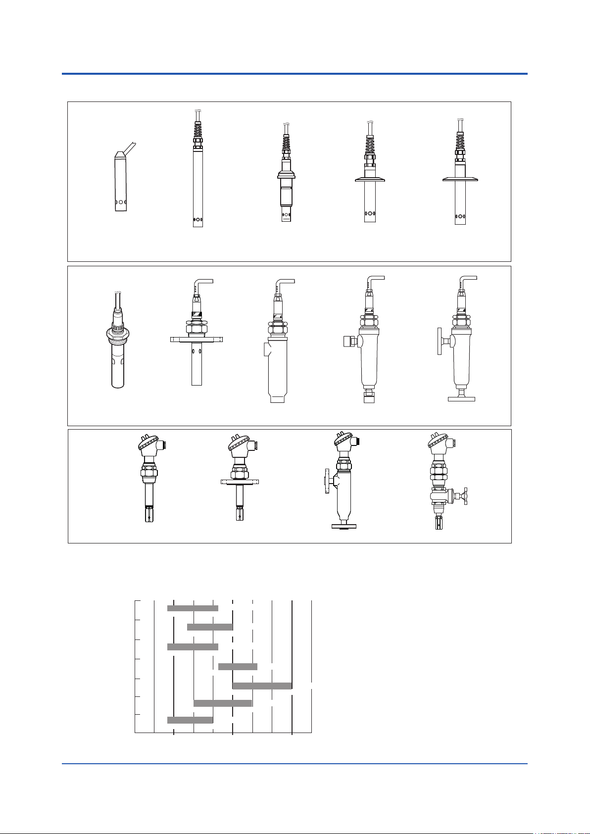
n Models of Conductivity Detectors/Sensors
SC4AJ
-AD-09
Adapter
Mounting Type
(Sensor length: 9 cm)
SC8SG
-
AD-15
Adapter
Mounting Type
(Sensor length: 15 cm)
-SA
Welding
Socket Type
1 or 1.5 inch welding
-SB
Clamp Type
2
--SC
2 inch welding
Clamp Type
Screw-in Type
Flange Type
Flow-through Type
(Screw Jointed)
Chamber Material : SCS14
Flow-through Type
(Screw Jointed)
Chamber Material : PP
SC210G
Screw-in Type
Flange Type
Flow-through Type Screw-in Type with Gate Valve
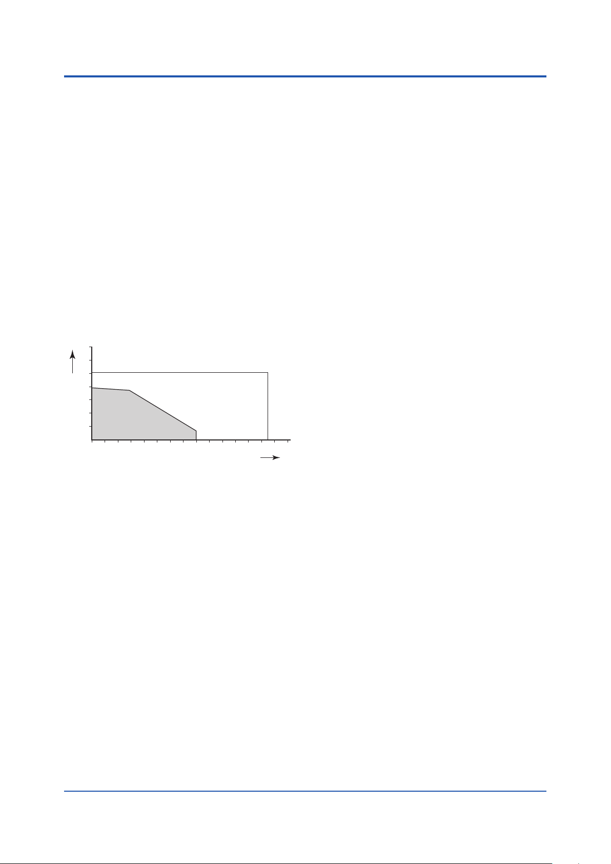
n RANGE OF MEASURING UPPER RANGE LIMIT OF
EACH SENSORS
Sensors
SC4AJ
SC4AJ
SC210G-A, -V
SC210G-B, -W
SC8SG-R61
SC8SG-R42
SC8SG-R31
0.5 µS/cm
5 µS/cm
0.5 µS/cm
10 µS/cm
0.5 µS/cm
1(µS/cm)
(C=0.02 cm-1)
200 µS/cm
(C=0.1 cm-1)
1 mS/cm
(C=0.05 cm-1)
200 µS/cm
200 µS/cm
1 mS/cm
(C=0.01 cm-1)
100 µS/cm
1(mS/cm)
Conductivity
(C=5 cm-1)
20 mS/cm
(C=0.1 cm-1)
10 mS/cm
(C=10 cm-1)
1 S/cm
1(S/cm)
Note
The bar graph at the left shows the range of the
upper range limit of each sensor.
For example, in the case of SC8SG-R61, the
measuring range is from 0-1 mS/cm to 0-1 S/cm.
In measurement in high conductivity range,
polluted solution may aect measured values of
any sensors. C represents cell constant.
Flow-through Type
(Flange Jointed)
F01.ai
All Rights Reserved. Copyright © 2010, Yokogawa Electric Corporation GS 12D08G02-E 17th Edition Dec. 20, 2019-00
Page 3
3
MPa
F03.ai
n GENERAL SPECIFICATIONS
1. SC4AJ:
Cable with pin terminals (applicable to FLXA202,
Cable with M4 ring terminals (applicable to FLXA202,
Cable with M3 ring terminals (applicable to FLXA402)
Variopin connector (applicable to SA11)
Object of measurement: Conductivity of solutions
Measuring principle: Two-electrode system
Cell constant: 0.02 cm-1, 0.1 cm
Measuring range:
For a cell constant: 0.02 cm
For a cell constant: 0.1 cm
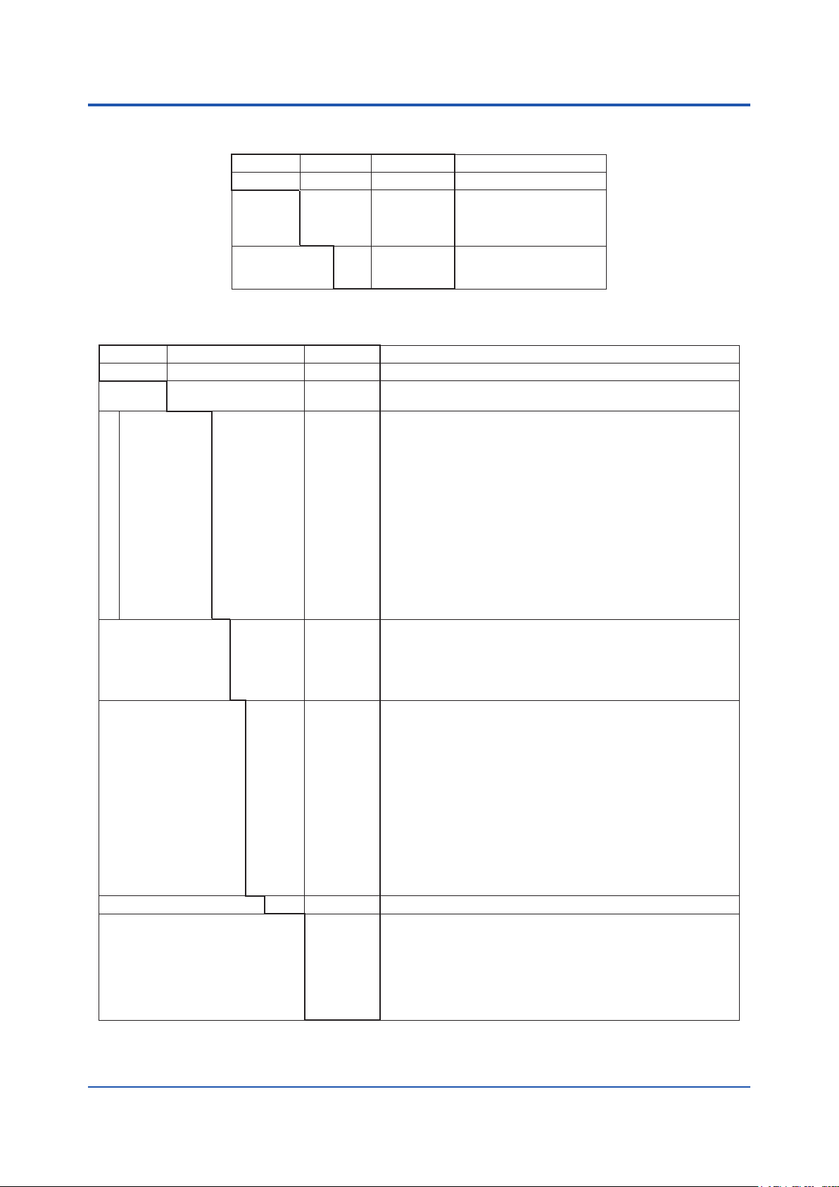
Temperature Range: For electrode, 0 to 110°C
For holder, see Figure 1
Sterilization for electrode:
135°C (275°F), within 30 minutes in
Pressure range : For electrode, 0 to 1 MPa
For holder, see Figure 1
1.2
1.0
0.8
0.6
0.4
0.2
Figure1: The range of tolerance of holders (option:
Sample solution condition:
Temperature sensor: Pt1000
Materials: Stainless steel (316L SS) (for all Fitting-
Mounting adapter: Polyvinylidene diuoride (for /PF
and /RF) or Stainless steel (316
SS), Stainless steel (316L SS)
Weight:
Sensors:
Adapter mounting type
Adapter mounting type
Welding socket type
1 or 1.5 inch welding clamp type
2 inch welding clamp type
FLXA21, FLXA402)
FLXA21)
-1
-1
:
0-0.5 µS/cm to 0-200 µS/cm
-1
:
0-5 µS/cm to 1 mS/cm
Steam Sterilization
SUS316L
PVDF
0 10 20 30 40 50 60 70 80 100 120 140
/PS, /PF, /RS, /RF, /SA1, /SA2, /SB1, /SB2,
/SC1) for temperature and pressure
Although ow rate is not limited in
measurement, air bubbles should not be
mixed in the sample solutions to obtain
correct measured values.
type) or Titanium (only for adapter
mounting type-AD), Fluoro rubber (FKM)
O-ring. EPDM O-ring (for -SA with Variopin)
(SC4AJ-S-AD-09-002-03): approx. 0.3 kg
(SC4AJ-S-AD-15-002-03): approx. 0.4 kg
(SC4AJ-S-SA-NN-002-03): approx. 0.5 kg
(SC4AJ-S-SB-NN-002-03): approx. 0.4 kg
(SC4AJ-S-SC-NN-002-03): approx. 0.5 kg
˚C
Note: There are weight dierences among SC4AJ
sensors. In order to know the more accurate
weight of each type of sensors, please calculate it
from following information. The cable weighs 0.07
kg/m. The SC4AJ with 0.02 cm-1 cell constant is
0.02 kg heavier than the SC4AJ with 0.1 cm-1 cell
constant. 314L SS electrode is 0.04 kg heavier
than Titanium electrode.
Adapters:
3/4NPT stainless steel adapter (/PS):
R3/4 stainless steel adapter (/RS):
3/4NPT PVDF adapter (/PF):
R3/4 PVDF adapter (/RF):
approx. 0.04 kg
approx. 0.04 kg
Straight welding socket (/SA1):
Angle welding socket 15 (/SA2):
Welding clamp 1 inch (/SB1):
approx. 0.3 kg
Welding clamp 1.5 inch (/SB2):
Welding clamp 2 inch (/SC1):
note: Do not submerge the sensor itself in process
water, as the seams between the mold and the
metal of the sensor are not waterproof.
approx. 0.4 kg
approx. 0.1 kg
approx. 0.1 kg
approx. 0.3 kg
approx. 0.3 kg
approx. 0.3 kg
2. SC8SG:
Cable with pin terminals (applicable to FLXA202,
Cable with M4 ring terminals (applicable to FLXA202,
Cable with M3 ring terminals (applicable to FLXA402)
Variopin connector (applicable to SA11)
Object of measurement:
Conductivity of liquids
Measuring Principle: 2-electrode system or
Cell Constants: 0.01 cm-1, 0.1 cm-1, 10 cm-1
(for two-electrode system)
Measuring Ranges: 0-0.5 µS/cm to 0-100 µS/cm
for a cell constant of 0.01 cm-1
0-10 µS/cm to 0-10 mS/cm
for a cell constant of 0.1cm
Temperature Range: 0˚ to 100˚C (130˚C maximum only for
0.01 cm-1 cell constant detectors,
excluding those with polypropylene
chambers)
Pressure: 1000 kPa max. (500 kPa maximum for
de
chambers)
Flow rate of Sample Solution:
No particular limitation applies,
Note: No limitation applies to ow rate (ow velocity)
RTD for Temperature Compensation:
Pt1000 (built into the sensor)
Construction: Direct insertion (in-situ) type or
Rainproof encapsulation
FLXA21, FLXA402)
FLXA21)
4-electrode system
10 cm-1 (for four-electrode system)
0-1 mS/cm to 0-1000 mS/cm
for a cell constant of 10 cm
tectors with polypropylene
although a value of less than 20
L/min. is recommended for ow-
through detectors.
as far as measurement is concerned. However,
when using ow-through detectors, electrodes or
the inner walls of a liquid chamber may be worn
out drastically at higher ow speeds if a measured
solution contains slurry. Air bubbles should not be
mixed in the sample solutions to obtain correct
measured values.
ow-through types.
(equivalent to JIS C0920
Japanese Industrial Standard)
-1
1
All Rights Reserved. Copyright © 2010, Yokogawa Electric Corporation GS 12D08G02-E 17th Edition Dec. 20, 2019-00
Page 4

4
Installation :
•Screw-in type: held by the process piping
No particular limitation applies,
•Flange type: held by the process piping
•Flow-through type (polypropylene chamber)
: mounted on a pipe (nominal diameter
of 50 mm ±2 in.)
•Flow-through type (SCS14 chamber)
: held by the process piping
Process Connection: Screw-in, Flange, ow-through
Construction of Wetted Part:
•Sensor-holding base:
316 SS) and Fluoro
Temperature sensor: Thermistor (PB36NTC)
Wet part Materials
•0.01 cm
Stainless steel (
rubber when using screw-in type holder
or the chamber made of stainless steel.
PP and Fluoro rubber when using the
chamber made of PP.
-1,
0.1 cm-1 cell constant, two-electrode
sensor:
Stainless steel (316 SS) and ethylene
chloride triuoride
-1
•10 cm
•10 cm
cell constant, two-electrode sensor:
reinforced epoxy resin and graphite
-1
cell constant, four-electrode sensor:
polyvinylidene diuoride (PVDF), glass
and platinum
•Stem (ow-through type):
SCS14 or polypropylene resin
Weight:
Screw-in type
approx. 0.9 kg (-R31) (excluding the cable)
Flange type
approx. 2.8 kg (-R31) (excluding the cable)
Flow-through type (SCS14 chamber)
approx. 3.1 kg (excluding the cable)
Construction: JIS C0920 watertight (equal to NEMA 4)
Weight:
Flow-through type (SCS14 chamber, anged)
approx. 4.5 kg (excluding the cable)
Flow-through type (polypropylene chamber)
approx. 2.7 kg (excluding the cable)
Flow-through type (polypropylene chamber, anged)
approx. 3.2 kg (excluding the cable)
Cable ; approx. 0.3 kg for 5.5 m length
; approx. 0.5 kg for 10 m length
; approx. 0.9 kg for 20 m length.
● WU41: Dedicated cable for the SC8SG
Cable : Six multicore wire
Diameter: 9.2 mm
Material : Thermoplastic PVC
3. SC210G:
Cable with pin terminals (applicable to FLXA202, FLXA21, FLXA402)
Cable with M4 ring terminals (applicable to FLXA202, FLXA21)
Cable with M3 ring terminals (applicable to FLXA402)
Object of measurement:
Conductivity of solutions
Measuring principle : Two-electrode system
Cell constant : 0.05 cm-1, 5 cm
Measuring range : 0-0.5 µS/cm to 0-200 µS/cm
(Cell constant: 0.05 cm
0-200 µS/cm to 0-20 mS/cm
(Cell constant: 5 cm
-1
-1
)
-1
)
Temperature Range: 0 to 105°C
(chamber material: SCS14)
0 to 100°C
(chamber material: Polypropylene)
Pressure range : 0 to 1 MPa
(chamber material: SCS14)
0 to 500 kPa
(chamber material: Polypropylene)
n Compliance with the simple ap
requirements
SC210G and SC4AJ meet the simple apparatus
requirements dened in the following standards.
Use the sensors under the conditions of use required
by the standards.
Applicable standards:
ANSI/ISA-60079-11 (2014)
ANSI/ISA-60079-0 (2009)
CAN/CSA-C22.2 NO. 60079-11:14
CAN/CSA-C22.2 NO. 60079-0:11
방호장치 의무안전인증 고시
GB 3836.4-2010
Flow rate of Sample Solution:
although a value of less than 20
L/min. is recommended for ow-
through detectors.
Note: No limitation applies to ow rate (ow velocity)
as far as measurement is concerned. However,
when using ow-through detectors, electrodes or
the inner walls of a liquid chamber may be worn
out drastically at higher ow speeds if a measured
solution contains slurry. Air bubbles should not be
mixed in the sample solutions to obtain correct
measured values.
SC210G-A: For sensor, Stainless steel (316 SS),
Fluoro rubber (FKM) (O-ring) and
Polytriuorochloroethylene For body,
Stainless steel (316 SS), polypropylene
and Fluoro rubber (FKM) (O-ring)
SC210G-B: For sensor, Platinum, glass and Fluoro
rubber (FKM) (O-ring)
For body, Stainless
steel (316 SS), polypropylene and
Fluoro rubber (FKM) (O-ring)
Flange (Flange type): Stainless steel (316 SS)
Flow-through type holder: SCS14 or polypropylene
resin, Fluororubber(FKM)
(O-ring)
Gate valve: SCS13A, Stainless steel (304 SS),
Stainless steel (316 SS Hard chrome
plating), Expanded graphite, PTFE
Screw-in type
approx. 2.1 kg (-L015) (excluding the cable)
Flange type
approx. 4.3 kg (-L015) (excluding the cable)
Flow-through type (SCS14 chamber)
approx. 3.7 kg (excluding the cable)
Flow-through type (SCS14 chamber, anged)
approx. 5.0 kg (excluding the cable)
Flow-through type (polypropylene chamber)
approx. 3.1 kg (excluding the cable)
Flow-through type (polypropylene chamber, anged)
approx. 3.3 kg (excluding the cable)
With gate valve
approx. 3.9 kg (excluding the cable)
Cable ; approx. 0.9 kg for 3 m length
; approx. 1.5 kg for 5 m length
; approx. 3.0 kg for 10 m length
; approx. 1.5 kg for 15 m length
; approx. 6.0 kg for 20 m length.
paratus
Note: TIIS certied types cannot be connected.
All Rights Reserved. Copyright © 2010, Yokogawa Electric Corporation GS 12D08G02-E 17th Edition Dec. 20, 2019-00
Page 5

Conditions of use:
(1) Use in combination with an internally isolated analyzer, or use with, an analyzer in combination with isolated
barrier.
The FLXA202/FLXA21 is internally isolated.
(2) Upper limit of the process temperature.
The upper limit of process temperature is indicated below when the sensor is used in combination with a
YOKOGAWA analyzer.
For FLXA202/FLXA21, model and sux code below is available.
FLXA21-D-□-D-◊-C1-○-A-N-LA-N-NN
□: can be any value.
◊: must be EA, CD, CH, or EG.
○: must be NN or C1.
Any option code is available.
FLXA202-D-□-D-◊-C1-○-A-N-LA-N-NN
□: can be any value.
◊: must be CD, CH, or CG.
○: must be NN or C1.
Any option code is available.
Upper limit of process temperature on the SC210G
Analyzer used in combination FLXA202/FLXA21
Ambient temperature Ta
40°C 60°C
Temperature class
T6 30 30
T5 95 (*1) 35
T4 105 45
T3 105 65
T2 105 105
T1 105 105
*1: Care about upper limit 100°C of temperature class T5 should be taken.
5
Upper limit of process temperature on the SC4AJ
Analyzer used in combination FLXA202/FLXA21
Ambient temperature Ta
40°C 60°C
Temperature class
T6 49 49
T5 95 (*1) 64
T4 110 99
T3 110 11 0
T2 110 11 0
T1 110 11 0
*1: Care about upper limit 100°C of temperature class T5 should be taken.
Other warnings are provided in the user’s manual.
■ Applicableanalyzerwithvariousdetectors
Detector SC4AJ SC8SG SC210G
Type of terminals Pin Ring M4 Ring M3 Pin Ring M4 Ring M3 Pin Ring M4 Ring M3
Analyzer: FLXA402 (*) Yes N.A. Yes Ye s N.A. Ye s Ye s N.A. Ye s
Analyzer: FLXA202 (*), FLXA21 Yes Ye s N.A. Yes Yes N.A. Ye s Yes N.A.
*: FLXA402 or FLXA202 when connected to a SA11 can be connected with sensors equipped with Variopin connector.
(SC4A..-VS, SC42-�V, SX42..�V, SC4AJ..-VS, SC8SG..-VS)
All Rights Reserved. Copyright © 2010, Yokogawa Electric Corporation GS 12D08G02-E 17th Edition Jan. 12, 2021-02
Page 6

n MODEL AND SUFFIX CODES
1. SC4AJ
Model SuxCode Option Code Description
SC4AJ
Material -T
Fitting type -AD
Sensor length -09
Cell constant -002
Cable length -03
Temperature sensor -T1
Option For AD only /PS
*1: When you select Fitting type -SA, place an order on the SC4AJ with Option code /SA1 or /SA2.
*2: When you select Fitting type -SB, place an order on the SC4AJ with Option code /SB1 or /SB2 (including seal ring),
When you select Fitting type -SC, place an order on the SC4AJ with Option code /SC1 (including seal ring).
*3: Washing treatment of wet part with alcohol.
*4: Used for connection to FLXA202, FLXA21.
*5: Used for connection to FLXA402, SC450G.
*6: Used for connection with SA11. Sensor length -09 is not selectable.
........................................................... ........................
.......................
-S
-SA
-SB
-SC
-15
-NN
-010
-05
-10
-15
-20
-X1
-X2
-X3
-X4
-X5
-Y1
-Y2
-Y3
-Y4
-Y5
-VS
For SA only /SA1
For SB only /SB1
For SC only /SC1 Welding clamp 2 inch 316L SS
Oil prohibit /DG1 Oil-prohibited use (*3)
.......................
.......................
.......................
.......................
.......................
.......................
.......................
.......................
.......................
.......................
.......................
.......................
.......................
.......................
.......................
.......................
.......................
.......................
.......................
.......................
.......................
.......................
.......................
.......................
.......................
.......................
.......................
/PF
/RS
/RF
/SA2
/SB2
Conductivity sensor
Titanium (Only for -AD)
316L SS
Adapter mounting type
Welding socket type (*1)
1 or 1.5 inch welding clamp type (*2)
2 inch welding clamp type (*2)
9 cm (Code for -AD)
15 cm (Code for -AD)
xed length (Code for -SA, -SB, -SC)
-1
0.02 cm
-1
0.1 cm
3 m (pin terminals)
5 m (pin terminals)
10 m (pin terminals)
15 m (pin terminals)
20 m (pin terminals)
3 m (M4 ring terminals) (*4)
5 m (M4 ring terminals) (*4)
10 m (M4 ring terminals) (*4)
15 m (M4 ring terminals) (*4)
20 m (M4 ring terminals) (*4)
3 m (M3 ring terminals) (*4)
5 m (M3 ring terminals) (*4)
10 m (M3 ring terminals) (*4)
15 m (M3 ring terminals) (*4)
20 m (M3 ring terminals) (*4)
Variopin connector (*6)
Pt1000
3/4NPT adapter 316 SS
3/4NPT adapter PVDF
R3/4 adapter 316 SS
R3/4 adapter PVDF
Straight welding socket 316L SS
Angled welding socket 15° 316L SS
Welding clamp 1 inch 316L SS
Welding clamp 1.5 inch 316L SS
6
Spare parts for SC4AJ
Parts No. Description
K9670MA
K9675VY
K9670MK
K9670MP
K9670MT
K9670MU
K9670MV
K9670MW
K9670MD
K9670ME
K9670MB
K9670MC
K9670ML
K9670MQ
All Rights Reserved. Copyright © 2010, Yokogawa Electric Corporation GS 12D08G02-E 17th Edition Dec. 20, 2019-00
O-ring for -SA (excluding -VS)
O-ring set for -SA (for -VS)
Seal rings for /SB1 or /SB2
Seal rings for /SC1
3/4 NPT Stainless steel adapter for -AD
3/4 NPT PVDF Adapter for -AD
R3/4 Stainless steel adapter for -AD
R3/4 PVDF Adapter for -AD
Angled welding socket and mounting nut for -SA
Staight welding socket for -SA
Angled welding socket for -SA
Straight welding socket for -SA
Welding clamp 1 or 1.5 inch for -SB
Welding clamp 2 inch for -SC
Page 7

2. SC8SG
Model SuxCode
SC8SG
Measuring
range
............................................. ...............
-R31
-R42
-R61
Electrode
-T
conguration
-F
Screw-in type
-100
-101
-102
Flange type
-206
-207
-208
Flow-through type
(*3)
Construction
-302
-312
-303
-313
-304
-314
-305
-315
Cable length -P1
-P2
-P3
-F1
-F2
-F3
-X1
-X2
-X3
-Y1
-Y2
-Y3
-VS
Style code *A
Option /PS
*1: Electrode conguration -F cannot be selected when -R31 or -R42 is selected.
When -R61 is selected, 2-electrode system -T is normally used, however, for process where detectors are susceptible to
contamination, a 4-electrode system -F should be used.
*2: If a welding socket (K9208BK) needs to be ordered beforehand, either place a separate order or prepare one by referring to
the extemal view later in this brochure.
*3: No chamber is equipped with a mounting hardware. Please place an order on the SC8SG with option code /PS or /SS
when you select ow-through model.
The PP chamber can have cracks or splits unless it is supported by a mounting hardware.
*4: Used for connection to FLXA202, FLXA21.
*5: Used for connection to FLXA402, SC450G.
*6: Used for connection with SA11. SC8SG-R61-T ( Measuring range: -R61 with Electrode conguration -T) is not selectable.
Spare Parts for SC8SG
Option
Code
..............
..............
..............
..............
..............
..............
..............
.............
.............
.............
.............
..............
..............
..............
..............
..............
..............
..............
..............
..............
..............
..............
..............
..............
..............
..............
..............
..............
..............
..............
..............
.............
..............
/SS
Description
Conductivity detector
Low range; cell constant: 0.01 cm
Medium range; cell constant: 0.1 cm
High range; cell constant: 10 cm
2-electrode system (for both 0.01 cm-1, 0.1 cm
-1
-1
-1
-1,
10cm-1 cell constants)
- for general measurements
4-electrode system (for 10 cm-1 cell constant only)
- for countermeasures against polarization due to contamination (*1)
with welding socket (*2)
without welding soket(a welding socket [K9208BK] should be ordered separately)
R1-1/2 material: SCS14
JIS 10 K 50 RF Flange
ANSI Class 150 2 RF ange (with serration)
JPI Class 150 2 RF ange
Rc1/2 female threaded; chamber material: SCS14
Rc1/2 female threaded; chamber material: PP
1/2NPT female threaded; chamber material: SCS14
1/2NPT female threaded; chamber material: PP
JIS 10K 15 RF ange; chamber material: SCS14
JIS 10K 15 FF ange; chamber material: PP
ANSI Class150 1/2 RF ange with serration; chamber material: SCS14
ANSI Class150 1/2 FF ange; chamber material: PP
5.5 m (special cable supplied with detector) (pin terminals)
10 m (special cable supplied with detector) (pin terminals)
20 m (special cable supplied with detector) (pin terminals)
5.5 m (special cable supplied with detector) (fork terminal)
10 m (special cable supplied with detector) (fork terminal)
20 m (special cable supplied with detector) (fork terminal)
5.5 m (special cable supplied with detector) (M4 ring terminal) (*4)
10 m (special cable supplied with detector) (M4 ring terminal) (*4)
20 m (special cable supplied with detector) (M4 ring terminal) (*4)
5.5 m (special cable supplied with detector) (M3 ring terminal) (*5)
10 m (special cable supplied with detector) (M3 ring terminal) (*5)
20 m (special cable supplied with detector) (M3 ring terminal) (*5)
Variopin connector (*6)
Style A
Stainless Steel
Stainless Steel
Mounting hardware (for PP chamber)
Mounting hardware (for SCS14 chamber)
7
Parts No. Description
K9208BA 0.01 cm
K9208BB 0.1 cm
K9208BC 10 cm
K9208BD 10 cm
K9208BV 0.01 cm
K9208BY 0.1 cm
K9208BZ 10 cm
-1
cell constant, two-electrode sensor
-1
cell constant, two-electrode sensor
-1
cell constant, two-electrode sensor
-1
cell constant, four-electrode sensor
-1
cell constant, two-electrode sensor, Variopin connector
-1
cell constant, two-electrode sensor, Variopin connector
-1
cell constant, four-electrode sensor, Variopin connecto
K9208BK Welding socket for screw-in model
G9303EB O-ring
All Rights Reserved. Copyright © 2010, Yokogawa Electric Corporation GS 12D08G02-E 17th Edition Dec. 20, 2019-00
Page 8
WU41
This cable can be purchased additionaly. SC8SG is supplied with cables of selected length.
Model Suxcode Option code Description
WU41
Cable end -F
Cable length -05
*1: Used for connection to FLXA202, FLXA21.
*2: Used for connection to FLXA402, SC450G
..................... ..........................
.........................
-10
-20
.........................
.........................
.........................
.........................
.........................
.........................
-P
-X
-Y
Dedicated Cable for SC8SG
fork terminals
pin terminals
M4 ring terminals (*1)
M3 ring terminals (*2)
5.5 m
10 m
20 m
3. SC210G
Model SuxCode Option Code Description
SC210G
Measuring
range
Screw-in type
Flange type
Flow-through
type (*1)
Construction
With gate valve
Sensor length -L015
Cable length -03
Style code *A
Option /SCT
*1: The model is not equipped with a mounting brackets, place an order on the SC210G with option code /PS or /SS when you
*2: Only for Screw-in type and Flange type
........................................... .......................
-A
-B
-100
-103
-206
-207
-208
-302
-312
-303
-313
-304
-314
-305
-315
-306
-402
-403
-L030
-L050
-L100
-L150
-L200
-05
-10
-15
-20
-AA
-BB
-CC
-DD
-EE
-Y1
-Y2
-Y3
-Y4
-Y5
select ow-through model. The PP chamber material can have cracks or splits unless it is not supported by a mounting
hardware.
......................
......................
......................
......................
......................
......................
......................
......................
......................
......................
......................
......................
......................
......................
......................
......................
......................
......................
......................
......................
......................
......................
......................
......................
......................
......................
......................
......................
......................
......................
......................
......................
......................
......................
......................
......................
......................
......................
......................
......................
/ANSI
/PF
/PS
/SS
/X1
/DG1
/MCT
Conductivity detector
Low range; cell constant: 0.05 cm
Medium range; cell constant: 5 cm
R1-1/2 male
1-1/2NPT male
JIS 10K 50 RF ange
ANSI Class150 2 RF ange (with serration)
JPI Class150 2 RF ange
Rc1/2 female, chamber material: SCS14
Rc1/2 female, chamber material: PP
1/2NPT female, chamber material: SCS14
1/2NPT female, chamber material: PP
JIS 10K 15 RF ange, chamber material: SCS14
JIS 10K 15 FF ange, chamber material: PP
ANSI Class150 1/2 RF ange with serration, chamber material: SCS14
ANSI Class150 1/2 FF ange, chamber material: PP
JPI Class150 1/2 RF ange, chamber material: SCS14
R1-1/4 male
1-1/4NPT male
150 mm (Standard)
300 mm (*2)
500 mm (*2)
1000 mm (*2)
1500 mm (*2)
2000 mm (*2)
3 m (M4 ring terminals) (*3)
5 m (M4 ring terminals) (*3)
10 m (M4 ring terminals) (*3)
15 m (M4 ring terminals) (*3)
20 m (M4 ring terminals) (*3)
3 m (pin terminals)
5 m (pin terminals)
10 m (pin terminals)
15 m (pin terminals)
20 m (pin terminals)
3 m (M3 ring terminals) (*4)
5 m (M3 ring terminals) (*4)
10 m (M3 ring terminals) (*4)
15 m (M3 ring terminals) (*4)
20 m (M3 ring terminals) (*4)
Style A
Stainless steel tag plate
With ANSI connection adaptor (*5)
DAI-ELperfrow (peruoro-elastomer) specication (*6)
SUS mounting hardware (for PP construction)
SUS mounting hardware (for SCS14 construction)
Epoxy-coated (baked)
Oil-prohibited use (Degrease cleaning treatment) (except for the type with gate valve)
Material Certicate (*7) (except for gate valve)
-1
-1
8
All Rights Reserved. Copyright © 2010, Yokogawa Electric Corporation GS 12D08G02-E 17th Edition Dec. 20, 2019-00
Page 9

*3: Used for connection to FLXA202, FLXA21.
*4: Used for connection to FLXA402, SC450G.
*5: Adaptor for cable inlet (carbon steel)
*6: Materials for O-ring of electrode assembly and chamber seal become peruoro-elastomer. But, in construction -402 and
-403, the sealing part of gate valve doesn’t become the elastomer.
*7: Additional lead time is required.
Spare Parts for SC210G
Name Part No. Remarks
-1
Electrode Assembly (*1)
(for SC210G-A)
Electrode Assembly (*2)
(for SC210G-A with gate valve)
Electrode Assembly (*1)
(for SC210G-B)
Electrode Assembly (*2)
(for SC210G-B with gate valve)
Cable K9315QA
O-ring K9050AT
*1: For the electrode assembly for oil-prohibited use (/DG1) and/or with material certicate (/MCT), please contact Yokogawa.
*2: For the electrode assembly with material certicate (/MCT), please contact Yokogawa.
K9208EA
K9208EB
K9208EC
K9208ED
K9208EE
K9208EF
K9315NA
K9315NB
K9315NC
K9315ND
K9315NE
K9315NF
K9208KA
K9315NN
K9208JH
K9208JF
K9208JB
K9208JC
K9208JD
K9208JE
K9208JJ
K9315NH
K9315NJ
K9315NK
K9315NL
K9315NM
K9208MA
K9315NP
K9315QB
K9315QC
K9315QF
K9315QG
K9315QR
K9315QS
K9315QT
K9315QU
K9315QV
K9315QJ
K9315QK
K9315QL
K9315QM
K9315QQ
K9050MR
K9319RN
150 mm (C=0.05cm
500 mm (C=0.05cm-1)
1000 mm (C=0.05cm-1)
1500 mm (C=0.05cm-1)
2000 mm (C=0.05cm-1)
300 mm (C=0.05cm-1)
150 mm (C=0.05cm-1) with peruoro-elastomer
300 mm (C=0.05cm-1) with peruoro-elastomer
500 mm (C=0.05cm-1) with peruoro-elastomer
1000 mm (C=0.05cm-1) with peruoro-elastomer
1500 mm (C=0.05cm-1) with peruoro-elastomer
2000 mm (C=0.05cm-1) with peruoro-elastomer
-1
(C=0.05cm
(C=0.05cm-1) with peruoro-elastomer
150 mm (C=5cm
300 mm (C=5cm-1)
500 mm (C=5cm-1)
1000 mm (C=5cm-1)
1500 mm (C=5cm-1)
2000 mm (C=5cm-1)
150 mm (C=5cm-1) with peruoro-elastomer
300 mm (C=5cm-1) with peruoro-elastomer
500 mm (C=5cm-1) with peruoro-elastomer
1000 mm (C=5cm-1) with peruoro-elastomer
1500 mm (C=5cm-1) with peruoro-elastomer
2000 mm (C=5cm-1) with peruoro-elastomer
(C=5cm
(C=5cm-1) with peruoro-elastomer
3 m (M4 ring terminals, SC210G...-03)
5 m (M4 ring terminals, SC210G...-05)
10 m (M4 ring terminals, SC210G...-10)
15 m (M4 ring terminals, SC210G...-15)
20 m (M4 ring terminals, SC210G...-20)
3 m (pin terminals)
5 m (pin terminals)
10 m (pin terminals)
15 m (pin terminals)
20 m (pin terminals)
3 m (M3 ring terminals)
5 m (M3 ring terminals)
10 m (M3 ring terminals)
15 m (M3 ring terminals)
20 m (M3 ring terminals)
Fluoro-rubber (FKM) O-ring (for screw-in type, ange type and ow-through type)
Fluoro-rubber (FKM) O-ring (for gate valve type)
Peruoro-elastomer O-ring (for all types)
)
-1
)
)
-1
)
9
All Rights Reserved. Copyright © 2010, Yokogawa Electric Corporation GS 12D08G02-E 17th Edition Jul. 10, 2020-01
Page 10

n DIMENSIONS
1. SC4AJ
˂Adapter mounting type˃
SC4AJ-p-AD-09
Sensor length: 09 (9 cm)
10
ø19.1
Cable length (3m, 5m, 10m, 15m, 20m)
SC4AJ-p-AD-15
Sensor length: 15 (15 cm)
ø19.1
90
Approx. 350
152
Pin-type Ring-type
57.6
Variopin connector
Unit: mm
Unit: mm
Cable length (3m, 5m, 10m, 15m, 20m)
Approx. 350
Pin-type Ring-type
●Option: Adaptermountingtype(-AD) /PS(StainlessSteel) /PF(PVDF)
/RS (Stainless Steel) /RF (PVDF)
Unit: mm
Approx. 49
3/4NPT or R3/4
All Rights Reserved. Copyright © 2010, Yokogawa Electric Corporation GS 12D08G02-E 17th Edition Dec. 20, 2019-00
Page 11

˂Welding socket type˃
SC4AJ-p-SA-NN
11
ø24.9
ø19.1
ø33.8
ø38
ø24.9
ø19.1
ø33.8
ø38
Cable length (3m, 5m, 10m, 15m, 20m)
95
95
Approx. 185
Approx. 350
●Option: Weldingsockettype(-SA)
Unit: mm
Variopin connector
189
O-ring
Pin-type Ring-type
Straight welding socket: /SA1 Angled welding socket: /SA2
51
8.5
55
ø42
Socket
thickness
(56.3)
(43.5)
8.5
Socket
ø42
Unit: mm
15°
thickness
All Rights Reserved. Copyright © 2010, Yokogawa Electric Corporation GS 12D08G02-E 17th Edition Dec. 20, 2019-00
Page 12

˂Weldingclamptype˃
SC4AJ-p-SB-NN
ø19.1
ø50.5
12
Unit: mm
Variopin connector
70
ø19.1
ø50.5
70
Cable length (3m, 5m, 10m, 15m, 20m)
Approx. 350
●Option: Weldingclamptype(-SB)
Welding clamp 1 inch: /SB1 Welding clamp 1.5 inch: /SB2
12.7
158
Approx. 160
12.7
Pin type
Ring type
Unit: mm
ø25.4
ø38.1
All Rights Reserved. Copyright © 2010, Yokogawa Electric Corporation GS 12D08G02-E 17th Edition Jan. 15, 2021-03
Page 13

Sensor SC4AJ-p-SC-NN
13
Unit: mm
ø64
ø25
ø64
ø19.1
ø19.1
80
80
Cable length (3m, 5m, 10m, 15m, 20m)
Approx. 350
167.3
Approx. 170
Variopin connector
Pin type
Ring type
●Option: Weldingclamptype(-SC)
Welding clamp 2 inch: /SC1
12.7
ø50.8
Unit: mm
All Rights Reserved. Copyright © 2010, Yokogawa Electric Corporation GS 12D08G02-E 17th Edition Dec. 20, 2019-00
Page 14

2. SC8SG
˂Screw-in type˃ Only the dierence between SC8SG-R □□-□-100 and SC8SG-R□□-□-101 is whether or not having a welding
socket. SC8SG-R □□-□-100 has a welding socket but SC8SG-R□□-□-101 does not.
14
SC8SG-R31-T-100 (Low range)
Electrode with 0.01cm
Two-electrode system
Locknuts
(M48x2)
45
Variopin connector
Outlet for
measured solution
SC8SG-R42-T-100 (Medium range)
Electrode with 0.1cm
Two-electrode system
Locknuts
(M48x2)
45
Variopin connector
Outlet for
measured solution
SC8SG-R61-T-100 (High range)
Electrode with 10cm
Two-electrode system
Welding
socket
Welding
socket
-1
Cell constant
95
95
ø30
-1
Cell constant
42
ø30
-1
Cell constant
Approx. 78
192
192
156
156
Approx. 78
138
102
Unit: mm
Pin terminals
Fork terminals
Ring terminals
Unit: mm
Pin terminals
Fork terminals
Ring terminals
Unit: mm
SC8SG-R61-F-100 (High range)
Electrode with 10cm
Four-electrode system
45
Variopin connector
measured solution
Locknuts
(M48x2)
Welding
socket
Outlet for
-1
Cell constant
133
26
ø29
Approx. 78
222
186
Welding socket
Parts No: K9208BK (Material: 316SS)
C1
C1
Note: If you make the welding socket for screw-in type,
refer to the above drawing.
ø55
ø42
ø45
ø50±0.2
22
3
27
3
(5)
Unit: mm
Pin terminals
Fork terminals
Ring terminals
Unit : mm
Locknuts
(M48x2)
Welding
socket
Outlet for
measured solution
125
ø30
All Rights Reserved. Copyright © 2010, Yokogawa Electric Corporation GS 12D08G02-E 17th Edition Dec. 20, 2019-00
Approx. 78
185
Pin terminals
Fork terminals
221
Ring terminals
Page 15

15
SC8SG-R31-T-102 (Low range)
Electrode with 0.01cm
-1
Cell constant
Two-electrode system
Locknuts
(M48x2)
45
R1-1/2
Variopin connector
Outlet for
measured solution
95
ø30
SC8SG-R42-T-102 (Medium range)
Electrode with 0.1cm
-1
Cell constant
Two-electrode system
Locknuts
(M48x2)
45
Approx. 78
192
Approx. 78
Unit: mm
Pin terminals
Fork terminals
Ring terminals
Unit: mm
Pin terminals
SC8SG-R61-F-102 (High range)
Electrode with 10cm
-1
Cell constant
Four-electrode system
Locknuts
(M48x2)
45
R1-1/2
Variopin connector
Outlet for
measured solution
133
26
Unit: mm
Pin terminals
Approx. 78
Fork terminals
222
Ring terminals
ø29
Variopin connector
R1-1/2
Outlet for
measured solution
42
SC8SG-R61-T-102 (High range)
Electrode with 10cm
-1
Cell constant
Two-electrode system
Locknuts
(M48x2)
R1-1/2
Outlet for
measured solution
125
Fork terminals
138
Ring terminals
ø30
Unit: mm
Pin terminals
Approx. 78
Fork terminals
221
Ring terminals
ø30
All Rights Reserved. Copyright © 2010, Yokogawa Electric Corporation GS 12D08G02-E 17th Edition Dec. 20, 2019-00
Page 16

˂Flange type>
16
Unit: mmSC8SG-R□□-□-20□
Variopin
connector
45
Locknuts
(M48×2)
øC
øD
Flange
138
H3
125
øC øD t
120
155
120.7
152.4
120.6
152
ø30
16
19.1
19.5
221
H3
133
<Insertion length>
øh
H1
19
127
19.1
124
20
123.5
26
H2
74
71
70.5
4-øh holes
191
t
H2
H1
95
SC8SG-R31-T SC8SG-R42-T SC8SG-R61-T SC8SG-R61-F
<Flange>
SC8SG - R□□ - □ - 206 - □□ *A
SC8SG - R□□ - □ - 207 - □□ *A
SC8SG - R□□ - □ - 208 - □□ *A
Outlet for
measured
solution
ø30
Model and Code
42
ø30
Flange rating
JIS 10K 50 RF
ANSI Class150 2 RF
JPI Class150 2 RF
Note: ANSI flange with serrations
Pin terminals
Approx. 78
Fork terminals
222
Ring terminals
ø29
H3
157
154
153.5
All Rights Reserved. Copyright © 2010, Yokogawa Electric Corporation GS 12D08G02-E 17th Edition Dec. 20, 2019-00
Page 17

˂Flow-throughtype˃
SC8SG-Rpp-p-302,
SC8SG-Rpp-p-303,
Screw connection (Chamber Material: SCS14)
Unit: mm
Variopin
connector
Pin terminals
●Option: Mounting hardware (-SS)
SCS14 Chamber
20
Approx.102
17
Unit : mm
45
Outlet
Rc1/2 or
1/2NPT(F)
Locknuts
42
172
Approx. ø58
Approx. 78
Fork terminals
260
Ring terminals
Inlet
Rc1/2 or
1/2NPT(F)
SC8SG-Rpp-p-304,
SC8SG-Rpp-p-305,
Flange connection (Chamber Material: SCS14)
Unit: mm
Variopin
connector
45
Locknuts
Approx. 78
Pin terminals
70
100
55
82
203
50A pipe
293
52
95
34.91515.71211.2
Fork terminals
Ring terminals
4-øh holes
øC
øD
All Rights Reserved. Copyright © 2010, Yokogawa Electric Corporation GS 12D08G02-E 17th Edition Dec. 20, 2019-00
øG
t
205
Flange rating øGøC øh t
JIS 10K 15 RF
ANSI Class150 1/2 RF
(with serretion)
75
70
60.5
øD
88.9
Page 18

SC8SG-Rpp-p-312, SC8SG-Rpp-p-313,
Screw connection (Chamber Material: PP) + Option (Mounting hardware (/PS)
Variopin
connector
18
Unit: mm
Pin terminals
45
203
47
Approx. 78
100
305
1/2NPT
Outlet
217
Rc1/2
40
87 99
170
Rc1/2
1/2NPT
Inlet
/PS
Mounting
hardware
SC8SG-Rpp-p-314, SC8SG-Rpp-p-315,
Flange connection (Chamber Material: PP) + Option (Mounting hardware (/PS) )
Variopin
connector
Pin terminals
Fork terminals
Ring terminals
JIS 50A pipe
53
Unit: mm
45
203
47
Approx. 78
4-ø15 holes
øC
øD
303
100
215
/PS
12
85 99
Mounting
hardware
Fork terminals
Ring terminals
JIS 50A pipe
98
Flange rating
JIS 10K 15 FF
ANSI Class150 1/2 FF7060.59588.9
øDøC
All Rights Reserved. Copyright © 2010, Yokogawa Electric Corporation GS 12D08G02-E 17th Edition Dec. 20, 2019-00
Page 19

● WU41 for SC8SG
19
Unit : mm
64.5
ø 29
15
16
11
12
PG9
Cable lengh:
14
13
Earth
3. SC210G
● SC210GDetector-converter connectioncable(accessory)
Black
T2
Red
White
Brown
To detector
T1
C1
C2
Approx. 75 Approx. 80
ø10.5
L
(3, 5, 10, 15, 20 m)
Approx. 100
5.5 m, 10 m, 20 m
Fork terminal
To converter
Ring terminal
Green
White
Yellow
Brown
Black
Red
Green
White
Yellow
Brown
Black
Red
Pin terminal
White
Brown
Green
Yellow
Black
Red
F22.ai
13
14
15
Ring terminals
16
12
11
13
14
15
Pin terminals
16
12
11
Unit: mm
● Option: WithANSIconnectionadaptor (/ANSI)
45
26
1/2NPT
ø15
G1/2
All Rights Reserved. Copyright © 2010, Yokogawa Electric Corporation GS 12D08G02-E 17th Edition Dec. 20, 2019-00
Unit: mm
Page 20

˂Screw-intype˃
SC210G-p-100, SC210G-p-103
20
Clearance for maintenance access
H+60
A : Mounting
screw
ø30
91
Approx.
H+184
H
26
SC210G-A, -VSC210G-B, -W
˂FlangeType˃
SC210G-p-206, SC210G-p-207, SC210G-p-208
Clearance for maintenance access
H+50
91
82
28
G1/2
Cable inlet
Gage
diameter
Approx.
H+10
< Mounting screw >
Model and Code A
SC210G - □ - 100
SC210G - □ - 103
< Sensor length >
Model and Code
SC210G - □ - 10□ - L015 - □ □ *A
SC210G - □ - 10□ - L030 - □ □ *A
SC210G - □ - 10□ - L050 - □ □ *A
SC210G - □ - 10□ - L100 - □ □ *A
SC210G - □ - 10□ - L150 - □ □ *A
SC210G - □ - 10□ - L200 - □ □ *A
82
Unit : mm
R 1-1/2
1-1/2 NPT
H
150
300
500
1000
1500
2000
Unit: mm
G1/2
Approx.
4 -øh holes
øC
øD
ø30
<Flange> <Sensor length>
Model and code
SC210G - □ - 206 -L □ □ □ - □ □ * A
SC210G - □ - 207 -L □ □ □ - □ □ * A
SC210G - □ - 208 -L □ □ □ - □ □ * A
Note : ANSI flange with serrations.
26
SC210G-ASC210G-B
JIS 10K 50 RF
ANSI Class150 2 RF
JPI Class150 2 RF
H+172
t
Flange rating
28
øC øD øht
120
155
120.7
152.4
120.6
152
19.1
19.5
16
Cable inlet
Approx.H
19
19.1
20
SC210G - □ - 20□ - L015 - □ □ * A
SC210G - □ - 20□ - L030 - □ □ * A
SC210G - □ - 20□ - L050 - □ □ * A
SC210G - □ - 20□ - L100 - □ □ * A
SC210G - □ - 20□ - L150 - □ □ * A
SC210G - □ - 20□ - L200 - □ □ * A
HModel and code
162
312
512
1012
1512
2012
All Rights Reserved. Copyright © 2010, Yokogawa Electric Corporation GS 12D08G02-E 17th Edition Dec. 20, 2019-00
Page 21

21
˂Flow-throughtype˃
SC210G-p-302, SC210G-p-303 *1
Screw connection (Chamber Material: SCS14)
Clearance for maintenance access
210
Outlet
Rc1/2 or
1/2NPT
91
Approx.
374
42
172
ø58
Inlet
Rc1/2 or
1/2NPT
*1: Refer to p17 for Dimension and Fitting of Option
(Mounting hardware (/SS)).
Unit: mm
82
G 1/2
Cable inlet
SC210G-p-312, SC210G-p-313
Screw connection (Chamber Material: PP)
Clearance for maintenance access
210
58
/PS
Mounting
hardware
99
91
40
Approx.
47
Rc1/2
1/2NPT
1/2NPT
Approx.
372
Outlet
170
B
82
Inlet
Unit: mm
G1/2
Cable inletRc1/2
100
JIS 50A pipe
SC210G-p-304, SC210G-p-305
SC210G-p-306 *1
Flange connection (Chamber Material: SCS14)
Clearance for maintenance access
210
91
t
øD øC
75
Approx.
409
205
ØCFlange rating
JIS 10K 15 RF
ANSI Class150 1/2 RF
JPI Class150 1/2 RF
70 1295 15
88.9
60.5
60.3 10.989 16
Note: ANSI flange is serration.
*1: Refer to p17 for Dimension and Fitting of Option
(Mounting hardware (/SS)).
82
ø58
Inlet
tØD Øh
11.2
Unit: mm
G 1/2
Cable inlet
Outlet
4-øh holes
15.7
SC210G-p-314, SC210G-p-315
Flange connection (Chamber Material: PP)
Clearance for maintenance access
210
/PS
Mounting
hardware
98
91
Approx.
t
øC øD
85
99
Flange rating
JIS 10K 15 FF
ANSI Class150 1/2 FF
419
Outlet
215
JIS 50A pipe
ØC ØD
70 95
60.5 88.9
t
12
12
Unit: mm
82
G 1/2
Cable inlet
100
4-øh holes
Inlet
Øh
15
15
All Rights Reserved. Copyright © 2010, Yokogawa Electric Corporation GS 12D08G02-E 17th Edition Dec. 20, 2019-00
Page 22

˂Withgatevalve˃
SC210G-p-402, SC210G-p-403
SC210G-A (Low range)
Clearance for maintenance access
210
91
Approx.
264
123
82
Unit : mm
G1/2
Cable inlet
SC210G-B (Medium range)
Clearance for maintenance access
225
91
22
Unit : mm
82
G1/2
Cable inlet
Approx.
410
Mounting screw
R1-1/4 or
1-1/4NPT
Gage diameter
Approx.
89
28
n WIRING DIAGRAM
SC4AJ Conductivity Sensor
(two-electrode system)
Applicable Analyzer:
FLXA402, SC450G, FLXA202, FLXA21
Approx.
155
26
11
12
13
14
15
16
Temperature
Electrode
Mounting screw
R1-1/4 or
1-1/4NPT
SC8SG Conductivity Detector
(two-electrode system, four-electrode system)
Applicable Analyzer:
FLXA402, SC450G, FLXA202, FLXA21
123
Gage diameter
Approx.
Approx.
133
199
ø30
11
Temperature
12
13
14
Electrode
15
16
11
Temperature
12
13
14
Electrode
15
16
F33.ai
SC210G Conductivity Detector
(two-electrode system)
Applicable Analyzer:
FLXA402, SC450G, FLXA202, FLXA21
All Rights Reserved. Copyright © 2010, Yokogawa Electric Corporation GS 12D08G02-E 17th Edition Dec. 20, 2019-00
Page 23

n TABLE OF CORROSION-RESISTANT MATERIALS
Note: This table shows corrosion resistances against each specied chemical only. If two or more kinds of chemical are mixed in
a sample, the properties may be dierent from those shown in this table.
Very suitable
Suitable
Slightly unsuitable
r
Í
Unusable
Hydrochloric acid 5 20
Hypohlorous acid 10 20
Nitric acid 10 20
Sulfuric acid
Inorganic acids
Phosphoric acid
Ammonia water 15 80
Caustic potash
Caustic soda
Alkali
Potassium carbonate 5 b
Sodium carbonate
Zinc chloride
Aluminum chloride
Ammonium chloride
Potassium chloride sat. 60 sat. 60 sat. 60
Calcium chloride sat. 80
Chlorides
Ferric chloride 20 40
Sodium chloride 20% + C12
(saturated) (Electrolyte)
Sea water 24
Ammonium sulfate 5 60 20 b
Potassium sulfatc 10 b 10 b 10 b
Sulfates
Sodium sulfate
Ammonium nitrate 20 b 20 b 20 b
Ni-
Sodium nitrate 50 b 50 b 50 b
trates
Sodium sulte 20 b 20 b
Hydrogen peroxide 10 30 10 30 10 30
Sodium hypochlorite 10 90
Potassium bichromate 10 b
Alcohol 96 70 100 b
Others
Acetic acid
Phenol
Aromatic solvent
(Note) b: Shows temperatures up to the boiling point. PVDF: Polyvinylidene diuoride
Holder material Electrode material
Polypropylene 316 SS
80
40
80
3 20
3 100
30 60
30 100
15 100
20 80
20 100
sat. 100 25 b 25 b 25 b
35 40
sat. 100
60
100
Good corrosion
resistance against
all salts normally
used
20 80
100 70 100 70
100 20 95 30
100 20
5 30
14 30
10 30 10 30
5 30
5 100
15 30
5 b
r
10 b
28 65
10 b
25 b
20 30
20 b
35 b
20 b
25 25
25 25
25 b
25 b
30 b
90
24
sat. 30
20 b 20 b 20 b
2 60 to 90
100 25
Í
Example of Description
Concentration Temperature Judgement
% ˚C
Epoxyresin PVDF
Í
5 30
10 60
Í
15 30
25 60
5 20
Í
10 60
5 30
25 100
10 b
28 65
10 60
25 b
20 60
20 b
5 b
35 b
r
20 60
Í
Í
r
25 20
25 b 25 b
Í
30 60
100
Í
90
r
60
20 b
sat. 30
Í
2 60 to 90
10 20
80 60
10 60
100 20
100 20
Í
Í
Í
Í
Í
Í
Í
Í
Í
Í
Í
Í
5 30
1 b
20 40
10 100
5 30
5 100
5 30
5 60
10 b
28 65
10 b
25 b
20 30
20 b
5 b
35 b
20 b
10 b
25 b
25 b
30 b
90
24
20 b
sat. 30
15 30
10 b
80 100
10 100
100 20
100
Í
Í
Í
O-ring material
Fluoro-rubber (FKM)
Strong acid
Weak acid
Strong alkali
Weak alkali
23
Seal
Í
r
CAUTION
Select the material of wetted parts with careful consideration of process characteristics. Inappropriate
selection may cause leakage of process fluids, which greatly affects facilities. Considerable care must be
taken particularly in the case of strongly corrosive process fluid such as hydrochloric acid, sulfuric acid,
hydrogen sulfide, and sodium hypochlorite. If you have any questions about the wetted part construction
of the product, be sure to contact Yokogawa.
All Rights Reserved. Copyright © 2010, Yokogawa Electric Corporation GS 12D08G02-E 17th Edition
Dec. 20, 2019-00
Page 24

24
ConductivityDetectors/SensorsInquirySpecications
Thank you for inquiry about YOKOGAWA Conductivity Detector/Sensor. Please check () the appropriate box () and
write down the relevant information in the underlined blanks.
1. General Items
Name of your company :
Person in charge : Belongs to: (Phone No.: )
Name of plant :
Measuring point :
Purpose of use : Indication Record Alarm Control
Power supply : V AC, Hz
2. Measuring Conditions
(1) Liquid temperature : to , Normal [˚C]
(2) Liquid pressure : to , Normal [kPa]
(3) Flow rate : to , Normal [L/min.]
(4) Flow speed : to , Normal [m/s]
(5) Slurry or fouling components: No Yes
(6) Name of measuring liquid :
(7) Component of measuring liquid :
(8) Others :
3. Installing Location
(1) Ambient temperature :
(2) Installing location : Outdoors Indoors
(3) Others :
4. SpecicationRequirements
(1) Measuring Range :
(2) Transmission output : 4 to 20 mA DC 0 to 20 mA DC
(3) Detector/Sensor : SC4AJ 2-electrode system (0.02 cm-1) 2-electrode system (0.1 cm-1)
SC8SG 2-electrode system (0.01 cm-1) 2-electrode system (0.1 cm-1)
2-electrode system (10 cm-1) 4-electrode system (10 cm-1)
SC210G 2-electrode system (0.05 cm-1) 2-electrode system (5 cm-1)
(4) Mounting type : SC4AJ Adapter mounting Welding socket Welding clamp
SC8SG Screw-in Flange Flow-through
SC210G Screw-in Flange Flow-through
Screw-in with gate valve
(5) Cable length : SC4AJ 3 m 5 m 10 m 15 m 20 m
none (SA11)
SC8SG 5.5 m 10 m 20 m none (SA11)
SC210G 3 m 5 m 10 m 15 m 20 m
(6) Others :
All Rights Reserved. Copyright © 2010, Yokogawa Electric Corporation GS 12D08G02-E 17th Edition
Subject to change without notice
Dec. 20, 2019-00
 Loading...