

Page 1

User’s
Model FX103/FX106/FX112
Model FX103/FX106/FX112
Manual
FX100
FX100
Yokogawa Electric Corporation
IM 04L20A01-01E
4th Edition
Page 2

Foreword
Thank you for purchasing the FX100. This manual describes the functions (excluding
the communications functions), installation and wiring procedures, operating procedures,
and handling precautions of the FX100. To ensure correct use, please read this manual
thoroughly before beginning operation. The following manuals are also provided in
addition to this manual. Read them along with this manual.
Electronic Manuals Provided on the Accompanying CD-ROM
Manual Title Manual No. Description
FX100 IM 04L20A01-17E Describes the communication functions of the
Communication Interface FX100 using the Ethernet/serial interface.
User’s Manual
DAQSTANDARD IM 04L20A01-61E Describes the functions and operating
User’s Manual procedure of the software “DAQSTANDARD”
that comes with the package.
Paper Manuals
Manual Title Manual No. Description
FX100 Operation Guide IM 04L20A01-02E A guide providing simple explanations of
operations for the FX100.
Support for the FX100 on IM 04L20A01-03E Describes the operation for scanning and
DAQLOGGER and recording data from the FX100 using
DAQEXPLORER DAQLOGGER and DAQEXPLORER.
Notes
Trademarks
• The contents of this manual are subject to change without prior notice as a result of
continuing improvements to the instrument’s performance and functions.
• Every effort has been made in the preparation of this manual to ensure the accuracy of
its contents. However, should you have any questions or find any errors, please contact
your nearest YOKOGAWA dealer as listed on the back cover of this manual.
• Copying or reproducing all or any part of the contents of this manual without the
permission of Yokogawa Electric Corporation is strictly prohibited.
• The TCP/IP software of this product and the document concerning the TCP/IP
software have been developed/created by YOKOGAWA based on the BSD
Networking Software, Release 1 that has been licensed from the Regents of the
University of California.
• Microsoft, MS-DOS, Windows, Windows XP, and Windows NT are either registered
trademarks or trademarks of Microsoft Corporation in the United States and/or other
countries.
• Adobe, Acrobat, and PostScript are trademarks of Adobe Systems incorporated.
• CompactFlash and CF are trademarks of SanDisk Corporation in the USA.
• For purposes of this manual, the TM and symbols do not accompany their
respective trademark names or registered trademark names.
• Company and product names that appear in this manual are trademarks or registered
trademarks of their respective holders.
Revisions
1st Edition October 2003 4th Edition May 2005
2nd Edition December 2003
3rd Edition April 2004
4th Edition : May 2005 (YK)
All Rights Reserved, Copyright © 2003 Yokogawa Electric Corporation
IM 04L20A01-01E
i
Page 3

Safety Precautions
The FX100 conforms to IEC safety class I (provided with terminal for protective grounding), Installation
Category II, and EN61326-1 (EMC standard), class A (use in a commercial, industrial, or business
environment).
This product is a measurement category II (CAT II) instrument.
* Measurement category II (CAT II)
Applies to measuring circuits connected to low voltage installation, and electrical instruments supplied with power from
fixed equipment such as electric switchboards.
The following general safety precautions must be observed during all phases of operation. If the FX100 is
used in a manner not specified in this manual, the protection provided by the FX100 may be impaired.
YOKOGAWA Electric Corporation assumes no liability for the customer’s failure to comply with these
requirements.
Please use this instrument as a measurement category II (CAT II) instrument.
This instrument is for indoor use only.
About This Manual
• This manual should be read by the end user.
• Read this manual thoroughly and have a clear understanding of the product before operation.
• This manual explains the functions of the product. YOKOGAWA does not guarantee that the product will suit
a particular purpose of the user.
• Under absolutely no circumstances may the contents of this manual be transcribed or copied, in part or in
whole, without permission.
• The contents of this manual are subject to change without prior notice.
• Every effort has been made in the preparation of this manual to ensure the accuracy of its contents.
However, should you have any questions or find any errors or omissions, please contact your nearest
YOKOGAWA dealer.
Precautions Related to the Protection, Safety, and Alteration of the Product
• The following safety symbols are used on the product and in this manual.
“Handle with care.” (To avoid injury, death of personnel or damage to the instrument, the operator
must refer to the explanation in the manual.)
Protective grounding terminal
Alternating current
• For the protection and safe use of the product and the system that integrates the product, be sure to follow
the instructions and precautions on safety that are stated in this manual whenever you handle the product.
Take special note that if you handle the product in a manner that violate these instructions, the protection
functionality of the product may be damaged or impaired. In such cases, YOKOGAWA does not guarantee
the quality, performance, function, and safety of the product.
• If you are replacing parts or consumable items of the product, make sure to use parts specified by
YOKOGAWA.
• Do not modify this product.
ii IM 04L20A01-01E
Page 4

Safety Precautions
WARNING
Power Supply
Ensure that the source voltage matches the voltage of the power supply before turning ON the power.
Protective Grounding
Make sure to connect the protective grounding to prevent electric shock before turning ON the power.
Necessity of Protective Grounding
Never cut off the internal or external protective earth wire or disconnect the wiring of the protective
earth terminal. Doing so invalidates the protective functions of the instrument and poses a potential
shock hazard.
Defect of Protective Grounding
Do not operate the instrument if the protective earth might be defective. Make sure to check them
before operation.
Do Not Operate in an Explosive Atmosphere
Do not operate the instrument in the presence of flammable liquids or vapors. Operation in such
environments constitutes a safety hazard.
Do Not Remove Covers
The cover should be removed by YOKOGAWA’s qualified personnel only. Opening the cover is
dangerous, because some areas inside the instrument have high voltages.
External Connection
Connect the protective grounding before connecting to the item under measurement or to an external
control unit.
Damage to the Protective Structure
Operating the FX100 in a manner not described in this manual may damage its protective structure.
Exemption from Responsibility
• YOKOGAWA makes no warranties regarding the product except those stated in the WARRANTY that is
provided separately.
• YOKOGAWA assumes no liability to any party for any loss or damage, direct or indirect, caused by the user
or any unpredictable defect of the product.
Handling Precautions of the Software
• YOKOGAWA makes no warranties regarding the software accompanying this product except those stated in
the WARRANTY that is provided separately.
• Use the software on a single PC.
• You must purchase another copy of the software, if you are to use the software on another PC.
• Copying the software for any purposes other than backup is strictly prohibited.
• Please store the original media containing the software in a safe place.
• Reverse engineering, such as decompiling of the software, is strictly prohibited.
• No portion of the software supplied by YOKOGAWA may be transferred, exchanged, sublet, or leased for
use by any third party without prior permission by YOKOGAWA.
IM 04L20A01-01E
iii
Page 5
Checking the Contents of the Package
Unpack the box and check the contents before operating the instrument. If some of the
contents are not correct or missing or if there is physical damage, contact the dealer
from which you purchased them.
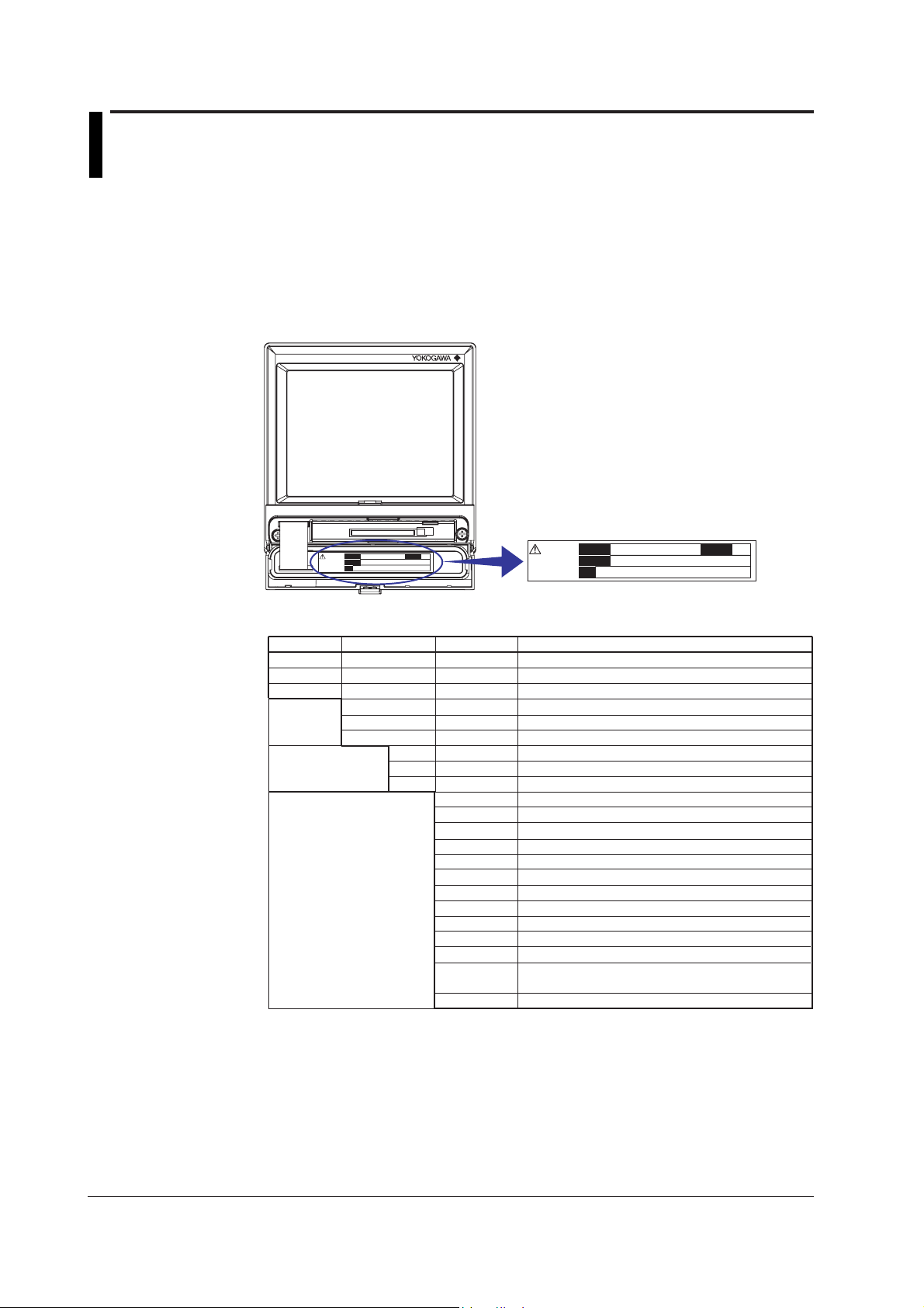
FX100
When you open the operation key panel on the front panel, a name plate is located on
the back side of the cover. Check that the model name and suffix code given on the
name plate on the rear panel match those on the order.
Do not remove
the cover.
Repair by trained
personal only.
MODEL
SUFFIX
NO.
STYLE
Do not remove
the cover.
Repair by trained
personal only.
MODEL and SUFFIX
Model
FX103
FX106
FX112
External
storage
medium
Displayed language
Options
*1 Only one can be specified at once.
*2 Either one can be specified.
*3 If /F1 is specified, /A3 cannot be specified.
*4 If /PM1 is specified, /A3, /M1, or /R1 cannot be specified.
If /PM1 is specified, /A2/F1 cannot be specified.
Suffix Code Optional Code Description
Number of inputs for measurement: 3ch
Number of inputs for measurement: 6 ch
Number of inputs for measurement: 12 ch
–0
–1
–4
–1
–2
–3
/A1
/A2
/A3
/C2
/C3
/C7
/F1
/M1
/N2
/N3
/P1
/PM1
No external memory
FDD
Compact flash memory card (with medium)
Japnese
English
Chinese
Alarm output relays 2 points
Alarm output relays 4 points
Alarm output relays 6 points
RS-232 interface (including Modbus protocol)
RS-422-A/485 interface (including Modbus protocol)
Ethernet (10BASE-T) interface
Fail/memory end detection and output
Mathematical function (report fuction included)
Three-terminal isolated RTD (input for measurement)
Pt1000 Ω RTD input
24 VDC/AC power supply
Pulse measurement input 3 points, Remote control
5 points*
/R1
Remote control 8 points
4
MODEL
SUFFIX
NO.
STYLE
*1
*1
*1
*2
*2
*3
NO. (Instrument Number)
When contacting the dealer from which you purchased the instrument, please give them
the instrument number.
iv IM 04L20A01-01E
Page 6

Standard Accessories
The standard accessories below are supplied with the instrument. Check that all
contents are present and that they are undamaged.
Checking the Contents of the Package
1
No. Name Part Number/Model Q’ty Note
1 Terminal screws 3 M4
2 Mounting bracket B9900BX 2 For panel mounting
3 DAQSTANDARD FXA100 1 CD-ROM used to install
4 FX100 B8703KA 1 CD-ROM containing the PDF files of this
electronic manual manual, the FX100 Communication
5 FX100 Operation IM 04L20A01-02E 1 A guide providing simple explanations of
Guide operations for the FX100.
Support for the FX100 on IM 04L20A01-03E 1 Describes the operation for scanning and
DAQLOGGER and recording data from the FX100 using
DAQEXPLORER DAQLOGGER and DAQEXPLORER.
6 CF memory card B9968NM 1 Compact flash memory card (32 MB,
2
Optional Accessories (Sold Separately)
The following optional accessories are available for purchase separately. When you
receive the order, check that all contents are present and that they are undamaged.
For information and ordering, contact your nearest YOKOGAWA dealer.
Part Name Part Number/Model Q’ty Note
CF memory card B9968NM 1 32 MB
Shunt resistor 4389 20 1 250 Ω±0.1%
Mounting bracket B9900BX 1
3
B9968NP 1 64 MB
B9968NQ 1 128 MB
B9968NR 1 256 MB
B9968NS 1 512 MB
4389 21 1 100 Ω±0.1%
4389 22 1 10 Ω±0.1%
4
5
“DAQSTANDARD,” software for setting
the FX100 and displaying data.
Interface User’s Manual, DAQSTANDARD
User’s Manual, and other files.
capacity and model of CF memory card
may vary) provided only when the
external storage medium suffix code is “4”
6
IM 04L20A01-01E
v
Page 7

How to Use This Manual
Structure of the Manual
This user’s manual consists of the following sections. For details on the communications
functions and the software “DAQSTANDARD” provided with the package, see the
respective manuals (IM 04L20A01-17E and IM 04L20A01-61E).
Chapter Title and Description
1 Explanation of Functions
Describes in detail the functions of the instrument. The chapters that explain the
operation of the FX100 only describe the operating procedures. For more detailed
information about the functions, see this chapter.
2 Installation and Wiring
3 Names of Parts, Display Modes, and Common Operations
4 Measurement Input and Alarm Related Setup Operations
5 Operations on the Operation Screens
6 Operations for Changing the Displayed Contents
7 Data Save/Load Operations
8 Computation and Report Function Related Operations (/M1 or /PM1 Option)
9 Operations of Other Functions
10 Troubleshooting
11 Maintenance
12 Specifications
Appendix Describes how to estimate the time for acquiring measured data to the internal memory,
Index
Describes the installation and wiring procedures of the FX100.
Describes the names of the parts of the FX100, the basic key operations, the basic
operations carried out initially, and how to use the external storage medium drive.
Describes how to set the input for the measurement and alarms.
Describes how to use the operation screens.
Describes how to change the display format and write user defined messages.
Describes how to write various data to the internal memory, how to save and load from
the external storage medium, and the file operations on the external storage medium.
Describes how to set and execute operations related to the computation function and
report function of the computation function option.
Describes the USER key, key lock, login/logout of key operation, log display, alarm on
internal memory remaining space, and remote input setting.
Describes the error messages and the troubleshooting measures of the FX100.
Describes periodic inspection, calibration, and recommended replacement period for
worn parts.
Describes the specifications of the FX100.
meaning and syntax of computation equations, data types the FX100 creates, the ASCII file
format, and a list of the setup items.
Note
• This user’s manual covers information regarding FX100s that have a suffix code for
language “-2” (English).
• For details on setting the displayed language, see section 3.6.
vi IM 04L20A01-01E
Page 8

Conventions Used in This Manual
Unit
K........ Denotes “1024.” Example: 768 KB (file size)
k........ Denotes “1000.”
Safety Markings
The following markings are used in this manual.
How to Use This Manual
Danger. Refer to corresponding location on the instrument.
This symbol appears on dangerous locations on the instrument
which require special instructions for proper handling or use. The
same symbol appears in the corresponding place in the manual to
identify those instructions.
WARNING
CAUTION
Note
Symbols Used on Pages Describing Operating Procedures
On pages that describe the operating procedures in Chapter 3 through 11, the following
symbols are used to distinguish the procedures from their explanations.
[]................ Indicates character strings that appear on the screen.
Procedure
Calls attention to actions or conditions that could cause serious
injury or death to the user, and precautions that can be taken to
prevent such occurrences.
Calls attentions to actions or conditions that could cause damage to
the instrument or user’s data, and precautions that can be taken to
prevent such occurrences.
Calls attention to information that is important for proper operation
of the instrument.
Example: [Space] soft key, [Volt]
This subsection contains the operating procedure used to carry out
the function described in the current section. All procedures are
written with inexperienced users in mind; experienced users may
not need to carry out all the steps.
IM 04L20A01-01E
Explanation
Setup Items
Describes the details of the settings and the restrictions that exist
with the operating procedure. It does not give a detailed
explanation of the function. For details on the function, see chapter
1.
vii
Page 9

Contents
Safety Precautions ..........................................................................................................................ii
Checking the Contents of the Package ..........................................................................................iv
How to Use This Manual ................................................................................................................vi
Chapter 1 Explanation of Functions
1.1 Overview of the FX100 .................................................................................................... 1-1
1.2 Functions of the Input Section ......................................................................................... 1-3
1.3 Alarm Function ................................................................................................................. 1-8
1.4 Display Function ............................................................................................................ 1-13
1.5 Data Storage Function ................................................................................................... 1-28
1.6 Computation Function and Report Function
(/M1, /PM1 Option) ......................................................................................................... 1-42
1.7 FAIL/Memory End Output Function (/F1 option) ............................................................ 1-50
1.8 Remote Control Function (/R1, /PM1 Option) ................................................................ 1-52
1.9 Other Functions ............................................................................................................. 1-55
Chapter 2 Installation and Wiring
2.1 Handling Precautions ....................................................................................................... 2-1
2.2 Installation ........................................................................................................................2-2
2.3 Measurement Input Terminal Wiring ................................................................................ 2-5
2.4 Optional Input/Output Terminal Wiring ............................................................................. 2-8
2.5 Wiring the Power Supply ................................................................................................ 2-12
Chapter 3 Names of Parts, Display Modes, and Common Operations
3.1 Names of Parts and Functions ......................................................................................... 3-1
3.2 Basic Key Operations ...................................................................................................... 3-3
3.3 Setting the Date and Time ............................................................................................. 3-10
3.4 Setting the Brightness of the Display and the Backlight Saver Function ....................... 3-13
3.5 Initializing the Setup Data and Clearing the Internal Memory ........................................ 3-14
3.6 Changing the Displayed Language ................................................................................ 3-15
3.7 Changing the Time Zone................................................................................................ 3-16
3.8 Confirming the System Configuration, Firmware Version Number,
and MAC Address of the FX100 .................................................................................... 3-17
3.9 Inserting and Ejecting the External Storage Medium ..................................................... 3-18
Chapter 4 Measurement Input and Alarm Setup Operations
4.1 Setting Parameters Related to Measurement Inputs ....................................................... 4-1
4.2 Setting Alarm Related Parameters................................................................................... 4-7
4.3 Setting Pulse Input (/PM1 Option) ................................................................................. 4-12
Chapter 5 Operations on the Operation Screens
5.1 Displaying Measured Data in Waveform, Numerical Values, or Bar Graph
(Trend, Digital, and Bar Graph Screens).......................................................................... 5-1
5.2 Displaying All Channels on a Screen (Overview Screen) ................................................ 5-4
5.3 Displaying Information List (Alarm Summary, Message Summary,
and Memory Summary) ................................................................................................... 5-5
5.4 Displaying Measured Data Previously Acquired (Historical Trend) .................................. 5-8
viii IM 04L20A01-01E
Page 10

Contents
Chapter 6 Operations for Changing the Displayed Contents
6.1 Change the Group Settings ............................................................................................. 6-1
6.2 Displaying Tag Names for Channels ................................................................................ 6-3
6.3 Changing the Display Update Rate of the Trend Screen ................................................. 6-5
6.4 Writing Messages on the Trend Screen ........................................................................... 6-6
6.5 Displaying a Line to Indicate a Particular Value of Interest (Trip Line)
on the Trend Screen ........................................................................................................ 6-8
6.6 Changing the Channel Display Color ............................................................................. 6-10
6.7 Displaying Waveforms in Separate Zones on the Trend Screen ................................... 6-12
6.8 Setting the Scale ............................................................................................................ 6-13
6.9 Setting the Waveform Display Direction, Background Color, Waveform Line Width,
Trip Line Width, and Grid ............................................................................................... 6-16
6.10 Changing the Display of Bar Graphs ............................................................................. 6-18
6.11 Switching the Displayed Groups Automatically at a Specified Time Interval
(Scroll Time) ................................................................................................................... 6-20
6.12 Displaying Partially Expanded Waveforms .................................................................... 6-21
Chapter 7 Data Save/Load Operations
7.1 Setting Measured Data Acquisition to the Internal Memory and Data Save
to the External Storage Medium ...................................................................................... 7-1
7.2 Starting/Stopping the Acquisition to the Internal Memory ................................................ 7-8
7.3 Saving Data to the External Storage Medium (Only for Models with an External
Storage Medium Drive) .................................................................................................. 7-10
7.4 Saving Measured Data at Arbitrary Times (Manual Sample) ......................................... 7-14
7.5 Saving the Screen Image Data (Snapshot) ................................................................... 7-15
7.6 Loading the Measured Data on the External Storage Medium (Historical Trend).......... 7-16
7.7 Managing Files and Checking the Free Space on the External Storage Medium ......... 7-17
7.8 Clearing the Data in the Internal Memory ...................................................................... 7-20
7.9 Saving and Loading Setup Data .................................................................................... 7-21
1
2
3
4
5
6
7
8
Chapter 8 Computation and Report Function Related Operations (/M1 or /PM1
Option)
8.1 Assigning Computation Channels and Setting Computing Equations, Constants
and Tags .......................................................................................................................... 8-1
8.2 Starting, Stopping, and Resetting the Computation ......................................................... 8-5
8.3 Setting Computation Channel Alarms .............................................................................. 8-7
8.4 Setting the Timer for Statistical Computations (TLOG Computation) and
Data Save (TLOG Data) .................................................................................................. 8-9
8.5 Setting the Rolling Average............................................................................................ 8-12
8.6 Creating Reports ............................................................................................................ 8-14
Chapter 9 Operations of Other Functions
9.1 Assigning an Action to the USER Key and Using the USER Key .................................... 9-1
9.2 Disabling Certain Keys (Keylock Function) ...................................................................... 9-2
9.3 Using Key Login/Logout Function .................................................................................... 9-5
9.4 Displaying a List of Record of Errors and Operations (Displaying Logs) ......................... 9-8
9.5 Monitoring the Remaining Space in the Internal Memory, and Outputting Alarms
(/F1 Option) .................................................................................................................... 9-10
9.6 Setting the Remote Control Function (/R1, /PM1 Option) ............................................. 9-11
9
10
11
12
App
Index
IM 04L20A01-01E
ix
Page 11

Contents
Chapter 10 Troubleshooting
10.1 A List of Messages ......................................................................................................... 10-1
10.2 Troubleshooting Flow Chart ........................................................................................... 10-9
Chapter 11 Maintenance
11.1 Periodic Inspection ............................................................................................................ 11-1
11.2 Calibration ......................................................................................................................... 11-2
11.3 Replacement of Parts ........................................................................................................ 11-4
Chapter 12 Specifications
12.1 Input Specifications ........................................................................................................ 12-1
12.2 Alarm Function Specifications ........................................................................................ 12-3
12.3 Display Specifications .................................................................................................... 12-4
12.4 Data Storage Specifications........................................................................................... 12-6
12.5 Specifications of Optional Functions .............................................................................. 12-9
12.6 General Specifications ................................................................................................. 12-13
12.7 Dimensional Drawings ................................................................................................. 12-17
Appendix
Appendix 1 Time Estimate for Writing Display/Event Data to the Internal Memory ................App-1
Appendix 2 Meaning and Syntax of Equations ....................................................................... App-6
Appendix 3 Pulse Measurement Setting Example (Pulse Sum Value Reset If It Exceeds a
Fixed Value) (/PM1 Option) ................................................................................App-11
Appendix 4 Types of Data Created on the FX100 and Their Uses .......................................App-13
Appendix 5 Data Formats of ASCII Files .............................................................................. App-14
Appendix 6 List of Parameters ..............................................................................................App-18
Index
x IM 04L20A01-01E
Page 12
Chapter 1 Explanation of Functions
1.1 Overview of the FX100
Measurement Input
DC voltage, thermocouple, resistance temperature detector, or ON/OFF signal (contact
signal or voltage signal) can be measured. The input signal is A/D-converted at a scan
interval and becomes a measured value of the channel. In addition, difference
computation, square-root computation, and scaling can be carried out on the measured
data to be a measured value of the channel. With the pulse measurement function (/
PM1 option), you can measure the number of pulses per unit time and pulse sum value.
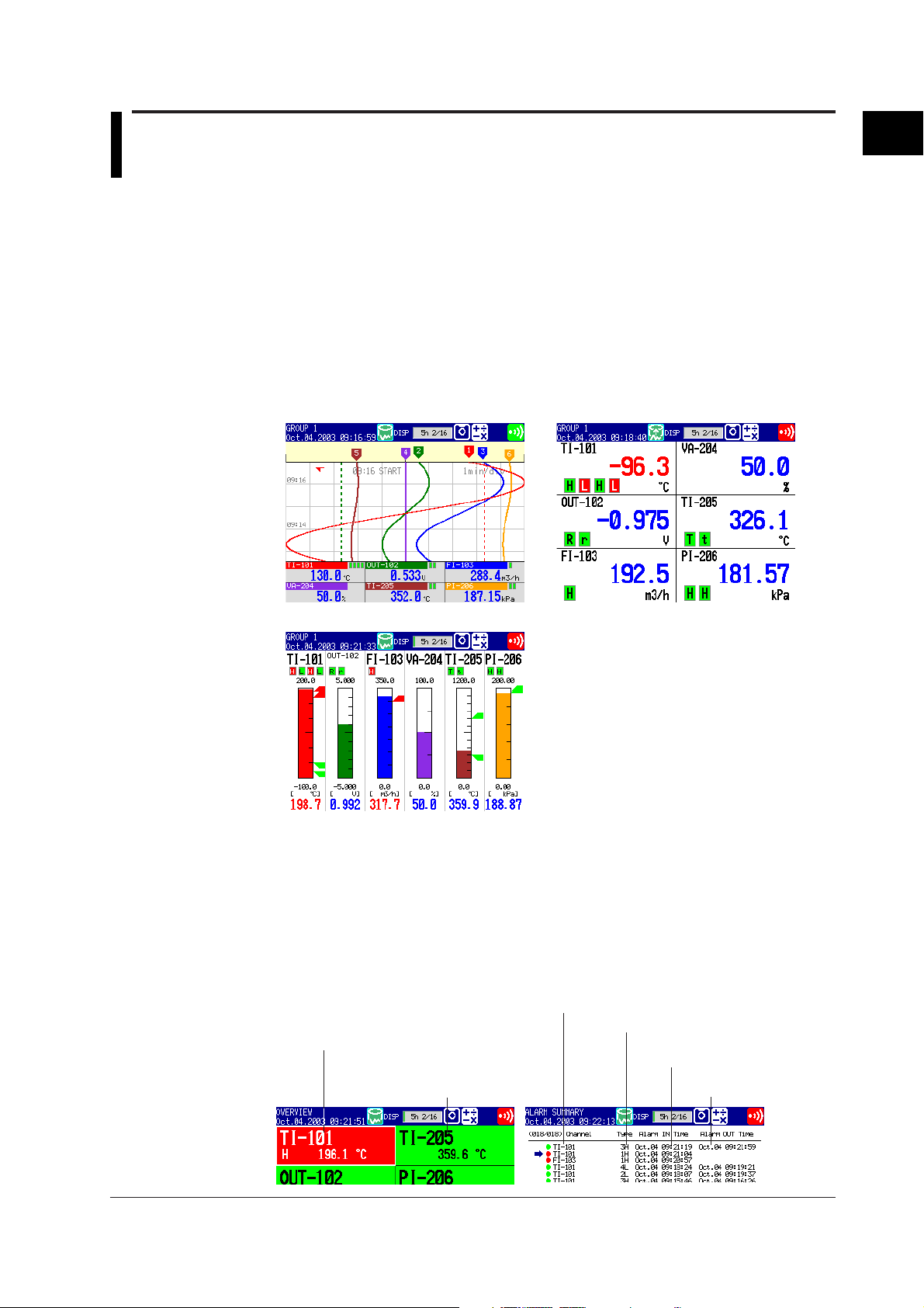
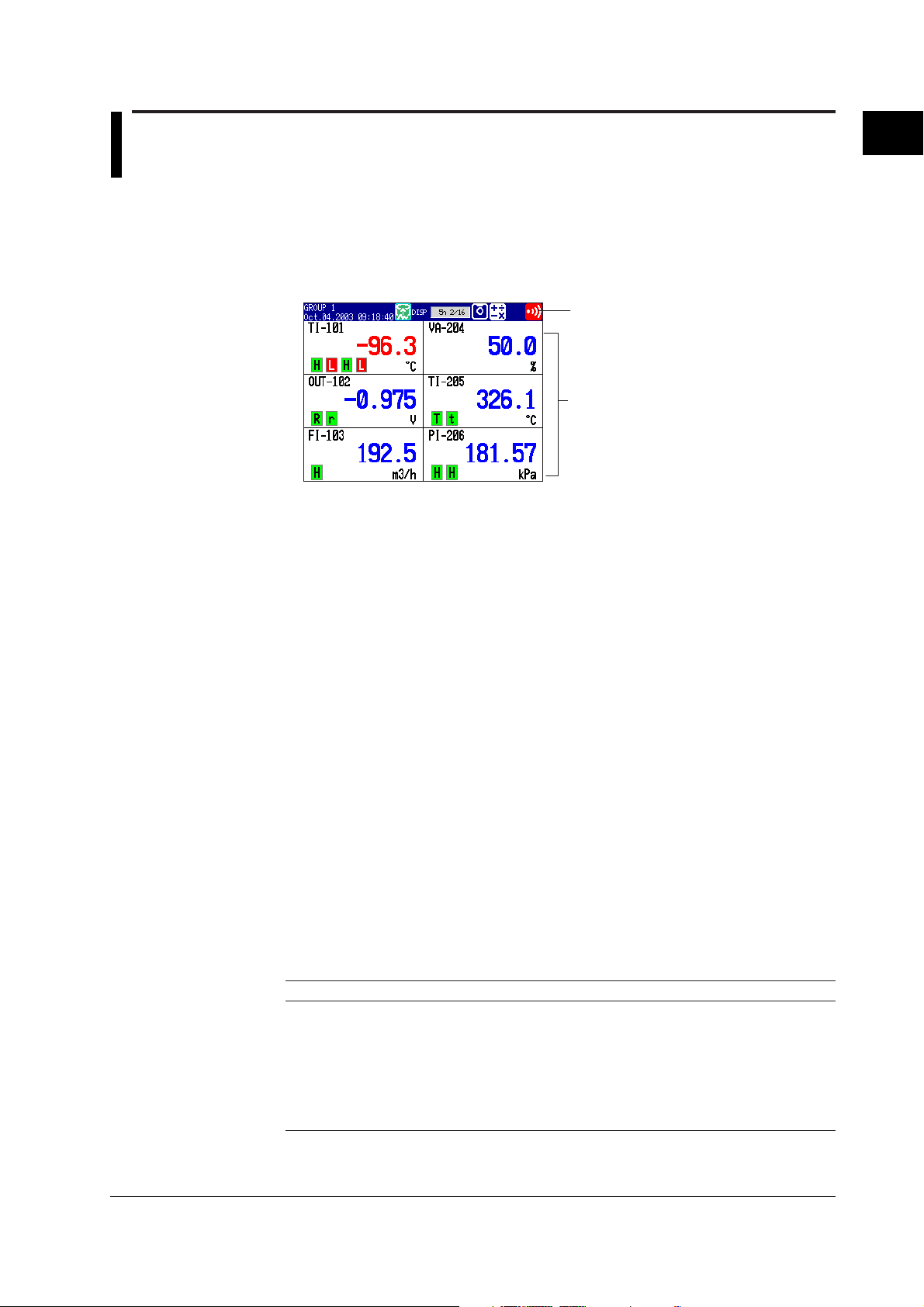
Displaying the Measured Data
The measured data acquired to the internal memory can be displayed on the operation
display using trend waveforms, numeric values (digital values), or bar graphs.
Trend Display Digital Display
1
Explanation of Functions
Alarms
Bar Graph Display
Alarms can be generated when the measured data meets a certain condition. When an
alarm occurs, you can have the information about the alarm displayed on the operation
screens. Also, you can output relay signals from the alarm output terminal on the option
terminal block (/A1, /A2, /A3 options). The overview display allows you to check the
alarm status on all channels. Also, the alarm summary shows detailed information about
the alarms in the order that they occurred.
Overview Display Example Alarm Summary Display Example
Alarm occurrence channel
Area of channels on which
an alarmis occurring is
indicated in red.
Area of channels on which
an alarm is not occurring
is indicated in green.
(channel No. or tag)
Alarm No. /type
Date and time when
the alarm occurred
Date and time when
the alarm was released
IM 04L20A01-01E
1-1
Page 13
1.1 Overview of the FX100
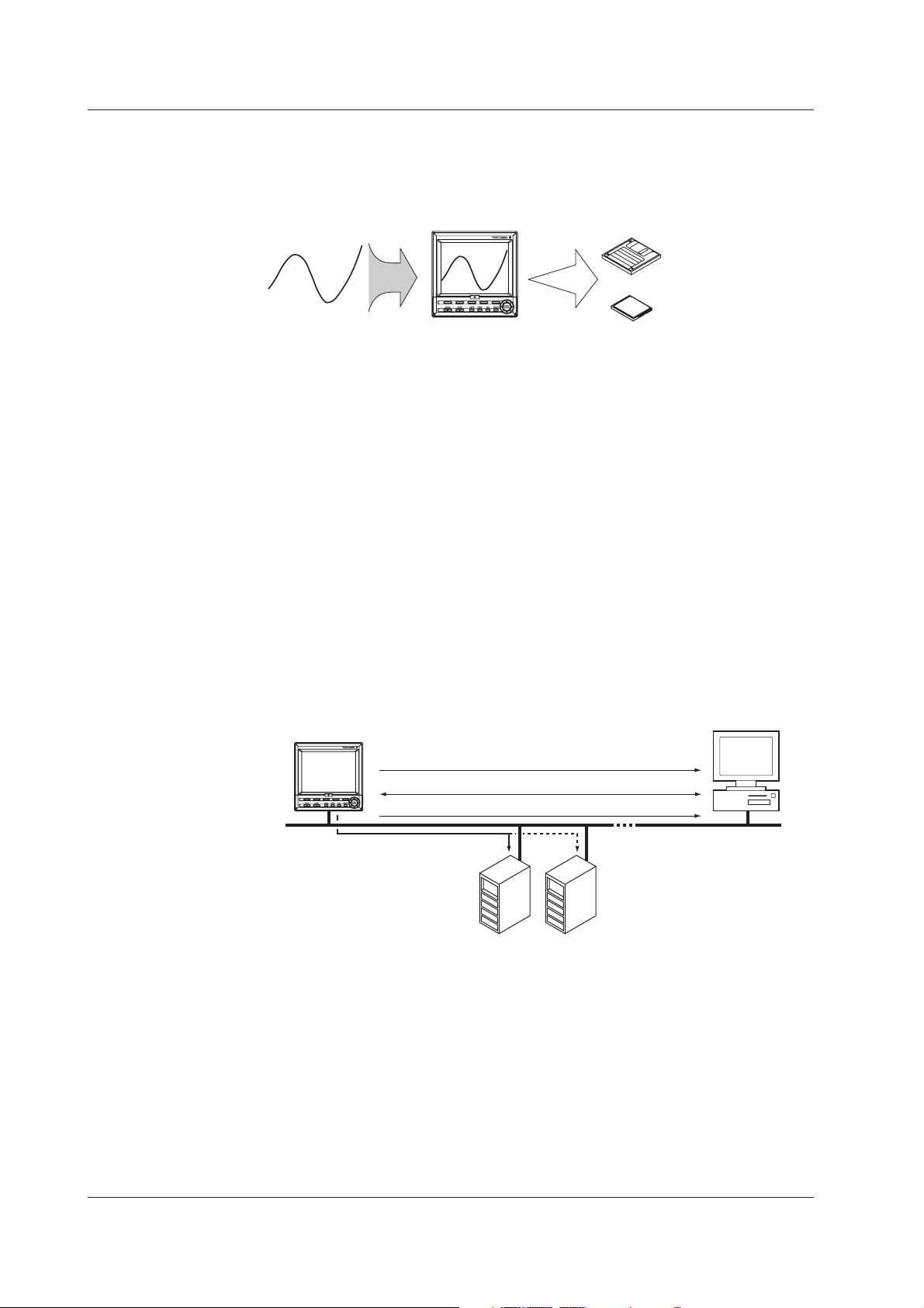
Saving Data
Communication Function
The measured data is acquired to the internal memory. The data in the internal memory
can also be saved to external storage media such as floppy disks (2HD) and compact
flash memory cards on models with a drive.
FX100
External Storage Medium
FD
CF memory card
The data that has been saved to an external storage medium can be displayed on a PC
using the DAQSTANDARD software that comes with the package. The data can also be
loaded into the FX100 to be displayed.
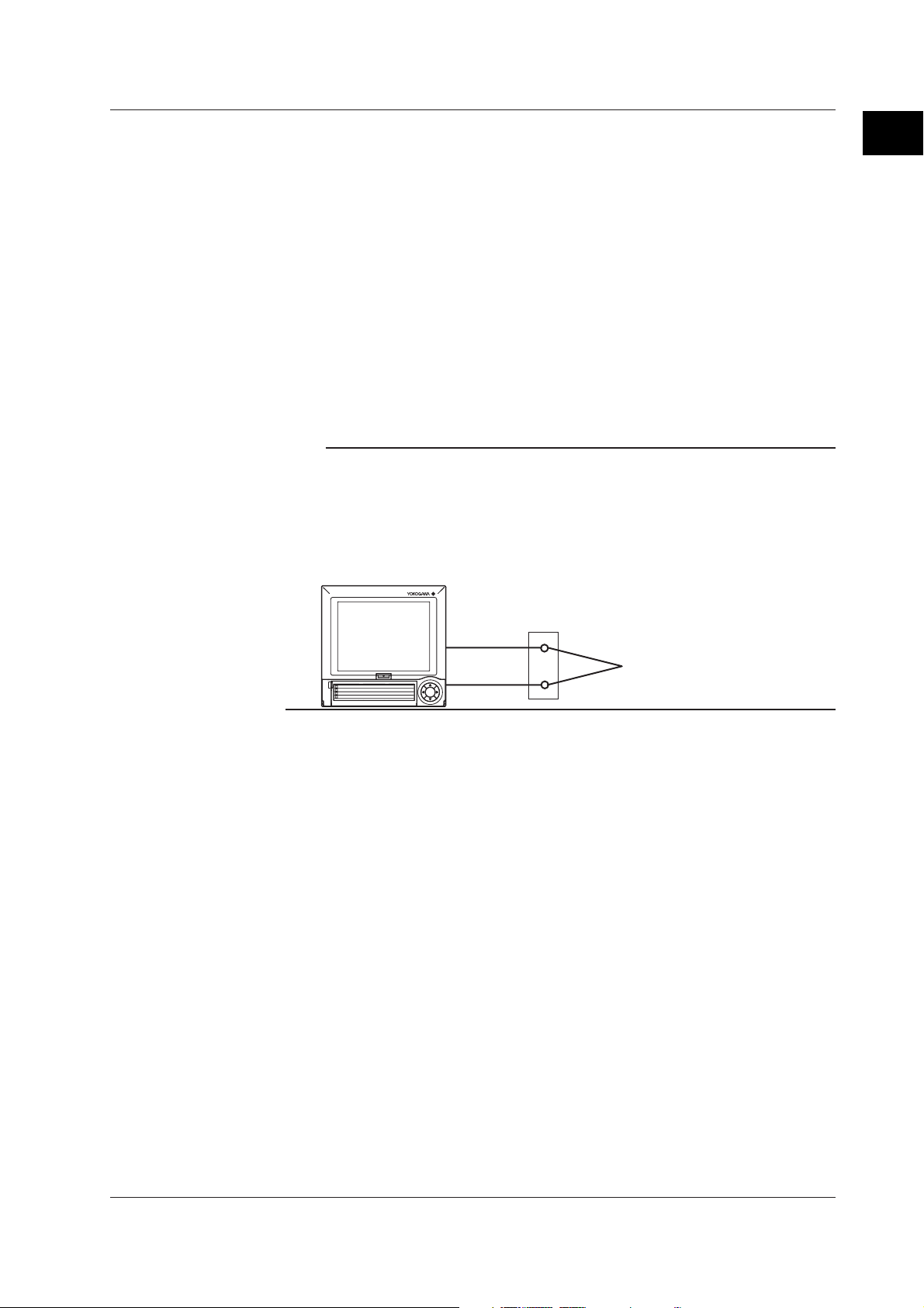
You can carry out the following types of operations by using the optional communication
functions (/C7, /C2, /C3).
• Operate the FX100.
• Configure the FX100.
• Monitor the measured data.
• Read the setup data or measured data from the FX100.
• Read files on the storage medium of the FX100.
You can also carry out the following types of operations by using the Ethernet
communication interface (/C7).
• Transmit the measured data in units of files to the FTP server on the network.
• Retrieve the files on the storage medium of the FX100 from a PC on the network.
• Display the screen of the FX100 on a Web browser on a PC.
• Transmit e-mail messages to preset recipients when events such as alarm
generations occur.
FX100
PC
DAQSTANDARD
1-2
Retrieves files on the external storage medium.
Displays the screen of the FX100 on a Web browser.
Transmits e-mail messages.
Transfers measured data files.
FTP server
Primary
Secondary
The communication functions using the Ethernet or serial interface are not covered in
this manual. See the ”
FX100 Communication Interface User’s Manual
” (IM 04L20A01-
17E).
By using the DAQSTANDARD that comes standard with the FX100, the following
operations are possible.
• Displaying the measured data
• Converting the measured data to ASCII, Lotus, or Excel formats
• Configuring the setup file for the FX100
See the “
DAQSTANDARD User’s Manual
” (IM 04L20A01-61E).
IM 04L20A01-01E
Page 14

1.2 Functions of the Input Section
Number of Measurement Channels/Scan Interval
The number of measurement channels and scan intervals for different models are listed
in the table below.
Model Number of Measurement Channels Scan Interval
FX103 3 channels 250 ms
FX106 6 channels 1 s or 2 s
FX112 12 channels 1 s or 2 s
Input Type and Computation
You can select the input type of a measurement channel from the table below. In
addition, difference computation, square-root computation, and scaling can be performed
on the measured data and display or save the computed result as measured data.
Input type Description
DC voltage Measures a DC voltage in the range of ±20 mV to ±50 V.
DC current The current signal is converted to a voltage signal by a shunt resistor
Thermocouple Measures temperatures corresponding to the temperature range of
Resistance temperature Measures temperatures corresponding to the appropriate range for
detector Pt100, JPt100, or Pt1000.
ON/OFF input Displays the contact input or voltage input signals by correlating them to
Pulse input For the description, see page 1-7.
*1 Pt1000 is optional (/N3 option).
attached to the input terminal and measured. The measurable range is
the range equivalent to the “DC voltage” range indicated above after
converting the current to the voltage signal.
each thermocouple type such as R, S, B, K, E, J, T, N, W, L, U, and
WRe3-25.
*1
0% or 100% of the display range.
Contact input: Closed contact is ON (1).
Open contact is OFF (0).
Voltage input: Less than 2.4 V is OFF (0).
Greater than or equal to 2.4 V is ON (1)
1
Explanation of Functions
IM 04L20A01-01E
Note
For converting a current signal to a voltage signal, three shunt resistors are provided (see
“
Optional Accessories (Sold Separately)
used to convert a 4 to 20 mA to a 1 to 5 V.
Measurable Range and Measurement Span
You can specify an arbitrary range for a measurement span within the measurable
range and display the measured data.
Measurable range
(Example: TC Type R)
1760.0°C
0.0°C
Measurement span
” on
page v
. A 250 W shunt resistor, for example, is
1500.0°C
(Upper limit of the measurement span)
300.0°C
(Lower limit of the measurement span)
1-3
Page 15

1.2 Functions of the Input Section
Difference Computation
The value obtained by subtracting the measured value of another channel (this
channel is called a “reference channel”) from the input value becomes a measured
value of the channel.
Input value
Note
Even if the input type or the measurement range of the difference computation channel and
the reference channel is not the same, the difference computation is performed according to
the following rules.
• When the decimal position between the reference channel and the difference computation
• When the units for the reference channel and the difference computation channel are
• When the reference channel is set to [Scale] or [Sqrt], the computation uses the scaled
Difference computation
+
−
Measured value of the reference channel
channel is different, the measured value of the reference channel is adjusted to the
decimal position of the measured value of the difference computation channel to make the
computation.
Example: When the measured value of the difference computation channel is 10.00 and
the measured value of the reference channel is 100.0, the computation result becomes
10.00 – 100.0 = –90.00.
different, the measured value is not adjusted.
Example: When the measured value of the difference computation channel is 10.00 V and
the measured value of the reference channel is 5.00 mV, the computation result becomes
10.00 V – 5.00 mV = 5.00 V.
values.
Measured
value
Scaling
The input value is converted to a value in the appropriate unit and the converted value
becomes a measured value of the channel.
Measured valueInput value
5 V 300.0 °C
1 V −100.0 °C
Square Root
When the input type is set to “DC voltage,” the square root of the input value is
computed. The computed result is scaled to a value in the appropriate unit and the
scaled value becomes a measured value of the channel.
Square root computation
Input value
√
Scaling
Measured
value
Note
• The FX100 uses the following square-root computation:
min
V – V
F = (F – F )
max
x min min
• Vmin: Lower limit of span • Fmin: Lower limit of scale • Vx: Input voltage
• Vmax: Upper limit of span • Fmax:Upper limit of scale • Fx: Scaling value
• When the value inside the square root is negative, the measured value is indicated as
when Fmin < Fmax: “–Over,” or when Fmin > Fmax: “+Over”.
x
max min
V – V
+ F
1-4
IM 04L20A01-01E
Page 16
1.2 Functions of the Input Section
Burnout Detection
When measuring temperature using a thermocouple and the thermocouple burns out,
you can specify the measurement result to be set to positive over range* or negative
over range.* Burnout can be set on each measurement channel.
* Positive over range is a condition in which the input signal is over the upper limit of the
measurable range. Negative over range is a condition in which the input signal is below the
lower limit of the measurable range. The measured value is indicated as “Burnout” for both
cases.
Reference Junction Compensation (RJC)
When measuring the temperature using a thermocouple, the reference junction
compensation can be used. You can select whether to use the reference junction
compensation provided by the FX100 or external reference junction compensation. If
you are using external reference junction compensation, you will also set the
reference voltage.
Note
When using the external reference junction compensation, set an appropriate reference
junction compensation voltage. As in the example in the following figure, if the reference
junction temperature for the external reference junction compensation is T0 °C, set the
thermoelectromotive force of the 0 °C reference for T0 °C as the reference junction
compensation voltage.
An example of External reference junction compensation
FX100
External reference junction compensation
(Maintain the junction between the
thermocouple and the copper wire at T
Copper wire
Thermocouple
0
°C)
1
Explanation of Functions
1
2
3
4
IM 04L20A01-01E
1-5
Page 17
1.2 Functions of the Input Section
Filter/Moving Average
The filter and moving average are used to suppress the effects of noise that is riding on
the signal. Filtering is provided on the FX103. Moving average is provided on the
FX106 and FX112. The filter or moving average can be set on each channel.
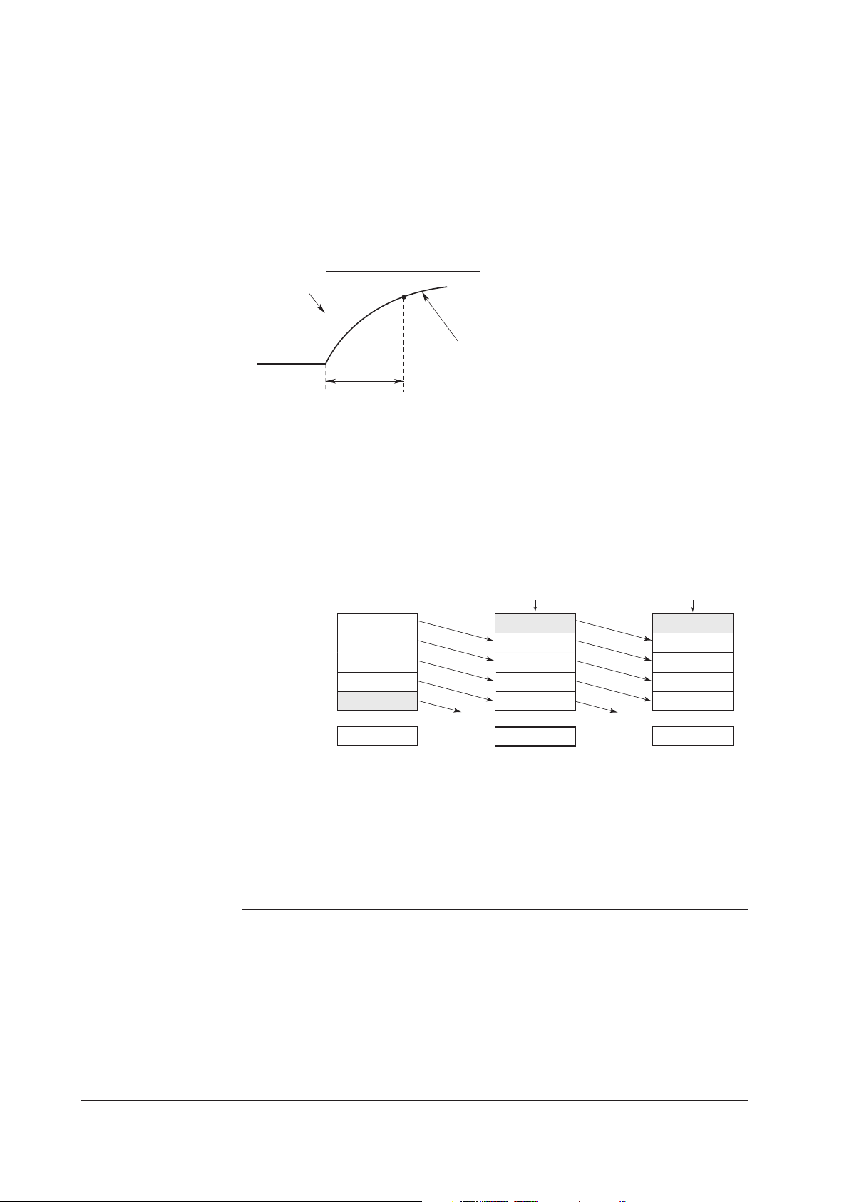
Filter Function (FX103)
Suppresses the effects of noise above the frequency determined by the specified time
constant. The time constant can be set to 2 s, 5 s, or 10 s.
Effects of using filter (Output response for a step input)
Input
Moving Average
The input signal of the measurement channel is set to the averaged value of the m
most current data points (the number of moving-averaged data points) acquired at the
scan interval. The number of moving-averaged data points can be set in the range 2
to 16.
The figure below shows an example indicating the operation of the buffer for the
moving average computation when the number of moving-averaged data points is set
to “5.”
Moving average value
63.2% of the output value
Output response curve (when using the filter)
2, 5, 10 s (time constant, the time it takes to reach 63.2% of the output value)
Buffer data at the
nth sampling
10.0mV
1
5.0mV
2
0.0mV
3
–5.0mV
4
–10.0mV
5
0.0mV
Deleted
Buffer data at the
n+1th sampling
New data
15.0mV
10.0mV
5.0mV
0.0mV
–5.0mV
5.0mV
Deleted
Buffer data at the
n+2th sampling
New data
10.0mV
15.0mV
10.0mV
5.0mV
0.0mV
8.0mV
Integration Time of the A/D Converter
The FX100 uses an A/D converter to convert the sampled analog signal to a digital
signal. By setting the integration time to match the time period corresponding to one
cycle of the power supply or an integer multiple of one cycle, the power supply frequency
noise can be effectively eliminated.
The integration time of the A/D converter is selected from the table below.
Model Integration Time of the A/D Converter
FX103 Select 16.7 ms (60 Hz), 20 ms (50 Hz), or Auto
FX106/FX112 Select 16.7 ms (60 Hz), 20 ms (50 Hz), 100 ms, or Auto
• If “Auto” is selected, the FX100 will automatically detect the power supply frequency
and select 16.7 ms or 20 ms. Fixed to 20 ms on /P1 models that use the 24 VDC
power supply.
• Because 100 ms is an integer multiple of 16.7 ms and 20 ms, this setting can be used
to eliminate the power frequency noise for either frequency, 50 Hz or 60 Hz.
However, when the integration time is 100 ms, the scan interval is fixed to 2 s.
1-6
IM 04L20A01-01E
Page 18
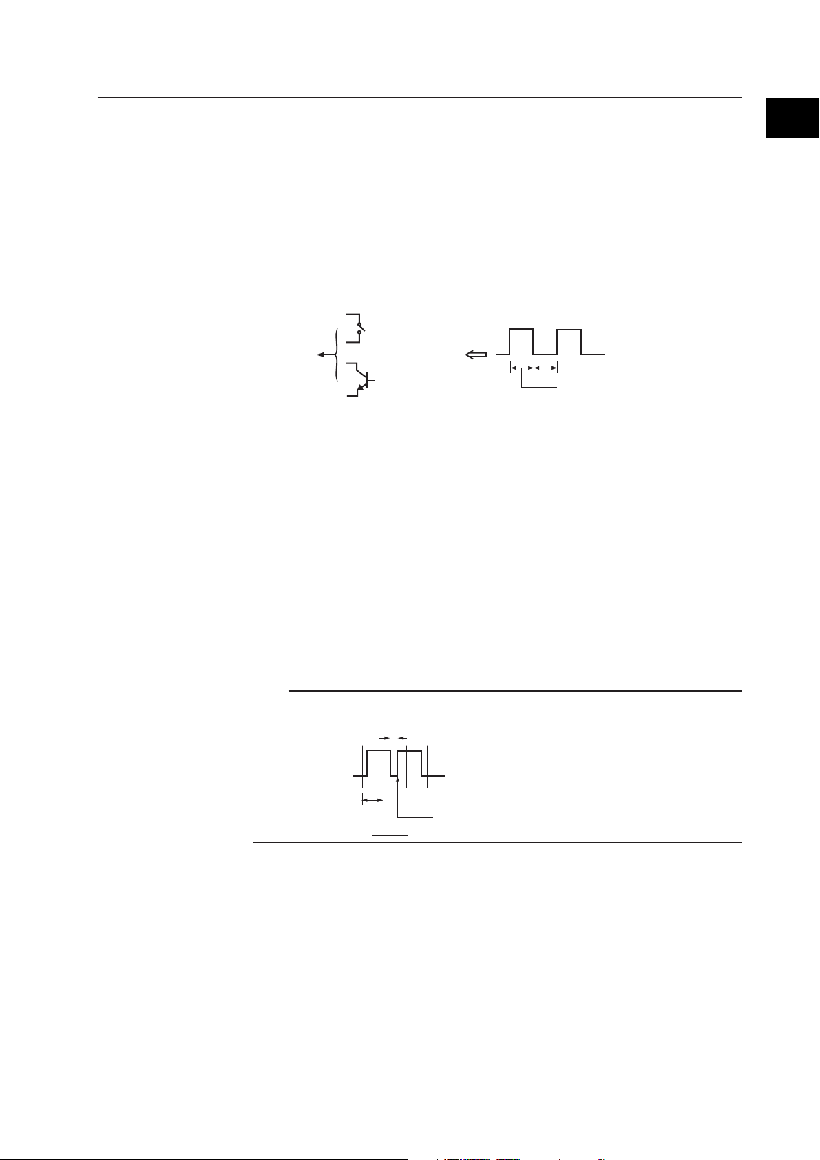
Pulse Input (/PM1 Option)
Contact or open collector signal pulses are input to the dedicated input terminals.
• Three inputs are available. However, the instrument can be expanded for up to 8
inputs.
• Pulses of 100 Hz or less whose Low (closed) and High (open) pulse widths are both 5
ms or more can be counted.
• The FX100 counts the following changes.
Contact signal pulse input: contact changes from open to closed
Open collector signal: input terminal level changes from High to Low
1.2 Functions of the Input Section
1
Explanation of Functions
Pulse
Less than or equal to 100Hz
Contact signal
FX100
or
Open collector
signal
More than or equal to 5 ms each
Counting Input Pulses
You can count and display the number of pulses input at each scan interval using
computation channels.
Sum Value
To display the pulse sum value, an equation is entered on the computation channels
to be displayed.
Number of Pulses per Unit Time
To display the number of pulses per unit time (1 s, 1 min, and 1hour), an equation is
entered on the computation channels to be displayed.
Using computation channels, sum of pulses are calculated and displayed.
For information about the computation function, see section 1.6, “
Report Function (/M1, /PM1 Option)
”.
Computation Function and
Note
The pulse detection interval is approximately 3.9 ms. If the pulse width is not 5 ms or greater,
the FX100 may not be able to detect it.
Less than 5 ms
IM 04L20A01-01E
Pulse signal
This change cannot be detected.
Pulse detection interval (approximately 3.9 ms)
1-7
Page 19

1.3 Alarm Function
This function generates an alarm when the measured/computed data meets a certain
condition. When an alarm occurs, information notifying the alarm occurrence is
displayed on the screen. In addition, a signal can be output from the relay output
terminals (/A1, /A2, or /A3 option) on the rear panel of the FX100.
Alarm Type
Number of Alarms
You can set up to four alarms for each channel.
Alarm Conditions
The following eight conditions are available. Letters in the parentheses are the
symbols used for each alarm.
• Upper limit alarm (H)
An alarm occurs when the measured value exceeds the alarm value.
• Lower limit alarm (L)
An alarm occurs when the measured value falls below the alarm value.
Upper limit alarm
Alarm occurrence
alarm value
Lower limit alarm
Measured
/computed data
Alarm release
Alarm release
Measured/computed data
• Difference upper limit alarm (h)
Alarm occurrence
*1
alarm value
An alarm occurs when the difference between the measured values of two channels
becomes greater than or equal to the alarm value.
• Difference lower limit alarm (l)
*1
An alarm occurs when the difference between the measured values of two channels
becomes smaller than or equal to the alarm value.
*1 Can be specified only on difference computation channels.
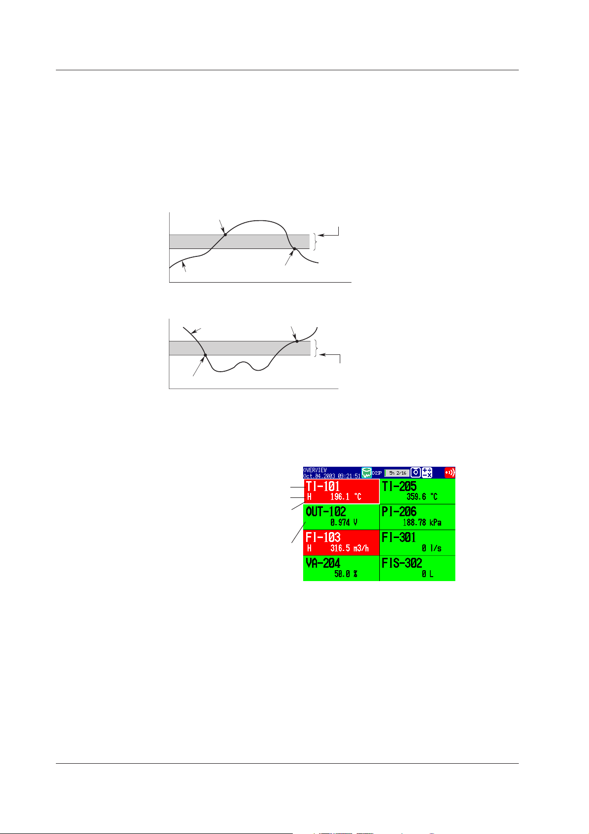
• Upper limit on rate-of-change alarm (R)
*2
The amount of change of the measured values over a certain time interval is checked.
An alarm occurs when the amount of increase becomes greater than or equal to the
specified value.
• Lower limit on rate-of-change alarm (r)
*2
The amount of change of the measured values over a certain time interval is checked.
An alarm occurs when the amount of decrease becomes greater than or equal to the
specified value.
*2 Can be specified only on measurement channels.
Upper limit on rate-of-change alarm
Measured
value
T2
Variation
2-T1|
T1
|T
R alarm
Lower limit on rate-of-change alarm
Measured
value
T1
Variation
T2
|T
2-T1|
1-8
r alarm
t1 t2 t1 t2
Interval t
Time
2-t1 Interval t2-t1
Time
The interval is defined by the following equation and is set in terms of the number of
measured data points.
Interval = scan interval × number of measurements
IM 04L20A01-01E
Page 20

1.3 Alarm Function
• Delay upper limit alarm (T)
An alarm occurs when the measured value remains above the alarm value for the
specified time period (delay period).
• Delay lower limit alarm (t)
An alarm occurs when the measured value remains below the alarm value for the
specified time period (delay period).
Delay upper limit alarm example (“T” is the specified delay period)
Measured/computed data
X1 X2 X3 X4
T1
T
Alarm value
Alarm releaseAlarm occurrence
• Alarm does not occur at T1, because the time period is shorter than the specified
delay period (T).
• The input exceeds the alarm value at X2, but the alarm occurs at X3 at which the
specified delay period elapses (the time when the alarm occurs is the time at X3).
• The input falls below the alarm value at X4 and the alarm is released.
Note
The following special operations are available for the delay upper/lower limit alarm.
• When a delay alarm is set on a computation channel (/M1, /PM1 option) and the
computation is stopped
If the computation is stopped in a condition in which the computed value is exceeding the
alarm setting, the alarm is turned ON after the specified period (delay period) elapses.
Computation stopped
1
Explanation of Functions
Alarm value
Computed data
• Delay alarm when a power failure occurs
Alarm detection is reset upon a power failure. It restarts the operation after the power
recovers.
Measured/computed data
T
Alarm : Off On Off On Off On Off
• Operation when the alarm setting is changed
• When a new delay alarm is set
The alarm detection starts at the time the alarm is set. It is unaffected by the conditions
existing before the alarm is set.
• If the alarm setting of a preexisting delay alarm is changed
• If an alarm is not occurring at the time of the change, alarm detection starts at the new
setting.
• If an alarm is occurring at the time of the change and the alarm type is set to delay
upper limit alarm, the alarm continues as long as the input is above or equal to the new
setting. If the input is below the new setting, the alarm turns OFF. If the alarm type is
set to delay lower limit alarm, the alarm continues as long as the input is below or equal
to the new setting. If the input is greater than the new setting, the alarm turns OFF.
TT
Power failure
occurence/recovery
T
Alarm turns ON
Alarm value
Power failure
occurence/recovery
IM 04L20A01-01E
1-9
Page 21
1.3 Alarm Function
Alarm Hysteresis
You can set a width (hysteresis) to the values used to activate and release alarms.
Alarm hysteresis prevents frequent activation and release of alarms when the measured
value is unstable around the alarm value. The hysteresis is fixed to 0.5% of the
measurement span (display scale width if the range is set to scale).
It is applied only on alarms set to upper/lower limit alarm on measurement channels.
The function can be turned ON/OFF. The initial value is set to [On] (use hysteresis).
The setting applies to all measurement channels.
Upper Limit Alarm (H)
Alarm Indication
Alarm occurrence
Measured value
Lower Limidt Alarm (L)
Measured value
Alarm occurrence
Alarm release
Alarm release
Alarm value
Hysteresis (approx. 0.5%)
Hysteresis (approx. 0.5%)
Alarm value
The alarm conditions are displayed as alarm icons in the status display section and
through the trend, digital, bar graph, overview and other screens. The detailed
information about the alarms is displayed in the alarm summary.
Alarm Indication Example (Overview screen)
Channel No. or tag name
Alarm type
Area of channels on which an
alarm is occurring is indicated
Area of channels on which an
alarm is not occurring is
indicated in green
in red
1-10
Hold/Non-Hold of the Alarm Indicator
There are two methods in displaying alarms. The initial value is non hold.
• Clears the alarm display when the cause of the alarm is no longer met (non-hold).
• Holds the alarm display until the alarm ACK operation is executed (hold).
The initial value is set to non-hold.
IM 04L20A01-01E
Page 22
1.3 Alarm Function
Alarm Output Relay (/A1, /A2, or /A3 option)
If you are using a model with the optional alarm output relay, a contact signal can be
generated according to the alarm conditions. The number of contact outputs for a/A1 to /
A3 are 2, 4, and 6 respectively. The alarm output relays are indicated using [I01] to [I06]
in the alarm output settings. The following functions can be specified on the alarm
output relay.
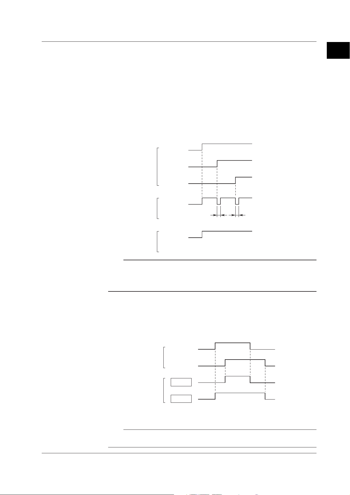
Reflash
When multiple alarms are set to one alarm output relay, this function notifies the
succeeding alarms after the first alarm that causes the relay activation. When a
succeeding alarm occurs, the output relay temporarily turns OFF (approximately 500
ms). The initial value is set to Off (do not use). The reflash alarm function is set only
to output relays I01, I02, and I03 (I01 and I02 for /A1 option).
Channel 1
Alarm status
Alarm relay status
(reflash: on)
Channel 2
Channel 3
Output relay
(option)
1
Explanation of Functions
(assuming I01 is assigned)
(assuming I01 is assigned)
(assuming I01 is assigned)
(I01 output)
Approx. 500 ms Approx. 500 ms
Alarm relay status
(reflash: off)
Output relay
(option)
(I01 output)
Note
If you set the reflash alarm, relays I01 to I03 become dedicated to reflash alarms regardless
of the number of alarm output relay points. Therefore, I01 to I03 operate as OR logic and
non-hold regardless of the settings made in “AND/OR of alarm output relays” and “Hold/Nonhold operation of the alarm output relay” on the next page.
AND/OR of Alarm Output Relay
When sharing an alarm output relay among multiple alarms, you can select from the
following conditions that cause the alarm output relay to be activated.
• AND: Activated when all alarms are being generated simultaneously.
• OR: Activated when at least one of the alarms is being generated.
Channel 1
Alarm status
Channel 2
AND
Alarm relay status
OR
IM 04L20A01-01E
Specify the alarm output relay to operate under the AND condition as in [I01 (first
relay) to Ixx (where xx is the relay number)].
Note
If the reflash alarm is turned ON, I01 to I03 are set to OR logic operation. Specifying AND
produces no effect.
1-11
Page 23

1.3 Alarm Function
Energize or De-energize Operation of the Alarm Output Relay
You can select whether to energize or de-energize the alarm output relay when the
alarm occurs. By selecting de-energize, the alarm output relay will operate in the
same manner as when the alarm occurs when the power supply is disrupted.
Energize or de-energize applies to all alarm output relays. The initial value is set to
Energize.
Energize
De-energize
NO
CNC NOCNC NO C NC
NO C NC NO C NCNO C NC
When power is turned OFF
NO: Normally opened, C: common, NC: normally closed
When no alarm occurs When an alarm occurs
Hold/Non-Hold Operation of the Alarm Output Relay
There are two methods in operating the alarm output relay.
• Turns OFF the output relay when the cause of the alarm is no longer met (nonhold).
• Holds the output relay ON until the alarm acknowledge operation is executed
(hold).
Non hold Hold
Alarm ACK Alarm ACK
Alarm
Alarm
Output Relay
Occurrence
Release
Activated
Released
Note
If the reflash alarm is turned ON, I01 to I03 are set to non-hold. Specifying hold produces no
effect.
Alarm Output Release (Alarm ACK) Operation
When you perform the alarm ACK procedure, all alarm displays and relay outputs (/
A1, /A2, /A3 option) are released. However, this procedure is not valid if the alarm
display/output relay operation is set to non-hold. This cancellation procedure can be
performed using FUNC key or USER key, or via remote control (/R1, /PM1 option).
Note
When the basic setting mode is entered, the activated/released condition of the previous
alarm output relay is held. Alarm detection is not carried out in the basic setting mode, and
you cannot release the alarm output relay.
1-12
IM 04L20A01-01E
Page 24
1.4 Display Function
Describes screens in the operation mode.
Common Items Related to the Display
5.5” TFT Color
The FX100 has a 5.5” TFT color LCD (240-by-320 dot resolution). The screen
consists of the status display section and the data display section.
• Status Display Section
Displays the displayed screen name, date and time, internal memory/external storage
medium usage condition, alarm condition, user name (when using the key login
function), computation condition (/M1, /PM1 option), status of key lock function and email transmission function (/C7 option).
• Data Display Section
Displays measured data using numerical values, waveforms, bar graphs, and so on.
Shows the setup screen when setting functions.
1
Explanation of Functions
Status display section
Data display section
Group Display
The data displayed on the trend, digital, and bar graph screens are the data of
measurement or computation channels that are assigned to the group. Up to 6
channels can be assigned to a single group. Up to 4 groups can be registered. The
groups are common to the trend, digital, and bar graph screens.
On the trend, digital, and bar graph screens, the displayed groups can be
automatically switched at 5 s, 10 s, 20 s, 30 s, or 1 min intervals.
Channel Number or Tag Name Display
The channels can be displayed as channel number or tags. The setting applies to all
channels.
Alarm Indication
Alarms are checked at all times and displayed on the relevant screens using alarm
type symbols.
Name Symbol
Upper limit alarm H
Lower limit alarm L
Difference upper limit alarm h
Difference lower limit alarm l
Upper limit on rate-of-change alarm R
Lower limit on rate-of-change alarm r
Delay upper limit alarm T
Delay lower limit alarm t
IM 04L20A01-01E
1-13
Page 25
1.4 Display Function
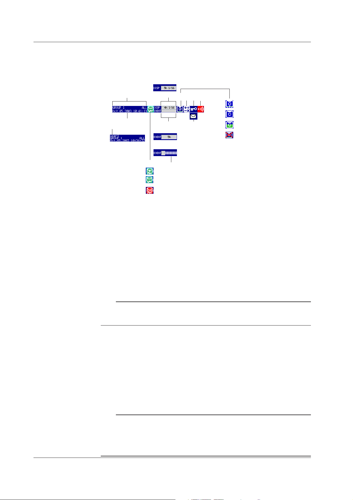
Status Indication Section
The following information is displayed in the status display section during operation
mode and setting mode. (The information is not displayed during basic setting mode.
[Setup Mode] is displayed instead.)
Display data
2
3
1
Event data/[Free] mode
Event data/[Trigger] or [Rotate] mode
4
A
B
C
7
6
The internal memory is
divided into 16 blocks.
859
11
D
E
10
F
G
1. User name
The user name is displayed when the key login function is used and the user is
logged in.
2. Group name or display name
The display name or group name corresponding to the display shown on the data
display section. [ALL] is displayed only when all channels are displayed on the
trend display (see page 1-17).
3. Current date and time
The current date and time are displayed.
4. Data acquisition to the internal memory ON/OFF
A and B is alternately displayed: Data being acquired or waiting for a trigger for
event data.
C: Data acquisition stopped
1-14
Note
For event data that starts sampling when the trigger condition is met, the display indicates
that sampling is in progress even in the trigger wait state. The trigger wait state can be
determined on the bar graph.
5. Memory usage of the display data acquisition area in the internal memory
Displayed when acquisition of display data is enabled.
For models with a storage medium drive
• The box indicates the amount of display data acquisition area in the internal
memory. The green bar shows the used space of the area.
• Time display indicates the remaining space of the display data acquisition area
in the internal memory.
• n/16
The maximum number of display data files that can be written to the internal
memory is 16. “16” represents this value. The value n is the number of display
data files in the internal memory.
Note
In the following cases, the display data is overwritten from the oldest file. Use caution
because the overwritten data is lost forever.
• When there is no more remaining space of the display data acquisition area in the internal
memory.
At this point, the status display section shows [Overwrite].
• When the number of display data files in the internal memory has exceeded 16.
IM 04L20A01-01E
Page 26

1.4 Display Function
For models without storage medium drive
Only the items below differ from “For models with a storage medium drive.”
• When “auto save” is specified
The box indicates a display data file. The green bar shows the progress of the
data acquisition. Time display shows the remaining time a display data file is
created.
For the description of “display data” and “auto save,” see section 1.5, “
Function
.”
Data Storage
6. Memory usage of the event data acquisition area in the internal memory
Displayed when acquisition of event data is enabled.
For models with a storage medium drive
• When the acquisition mode is [Free]
• The box indicates the amount of event data acquisition area in the internal
memory. The green bar shows the used space of the area.
• Time display indicates the remaining time of the event data acquisition area
in the internal memory.
• n/16
The maximum number of event data files that can be written to the internal
memory is 16. “16” represents this value. The value n is the number of
event data files in the internal memory.
For the description of “free mode,” see “1.5 Data Storage Function.”
Note
In the following cases, the event data is overwritten from the oldest file. Use caution because
the overwritten data is lost forever.
• When there is no more remaining time of the event data acquisition area in the internal memory
The status display section shows [Overwrite].
• When the number of event data files in the internal memory has exceeded 16
1
Explanation of Functions
• When the mode is [Trigger] or [Rotate]
• Bar graph
Displays the acquisition time (amount of memory used with respect to the
data length) of the specified event data.
When pretrigger is specified and START is pressed causing the FX100 to
enter the trigger wait state, data of size equal to the pretrigger amount is
acquired to the internal memory. At this point the bar is displayed in orange.
After acquiring the data of size equal to the pretrigger, the length of the bar
stays fixed. However, the relevant data is updated until the trigger condition
is met. When the trigger condition is met, the bar turns green. Data is
acquired to the internal memory after the pretrigger data.
If data acquisition to all blocks is finished in [Trigger] mode, [Full] (or [F]) is
displayed in the bar. When [Full] (or [F]) is displayed, event data is not
acquired to the internal memory even if the trigger condition is met.
For the description of “trigger mode” and “rotate mode,” see section 1.5, “
Function
.”
• Block display
When the event data acquisition area is divided into multiple blocks, the block
usage is displayed.
White blocks: Blocks with no data.
Green blocks: Block containing data that was acquired to the internal
memory after starting the current acquisition of event data.
Gray blocks: Blocks containing previous data.
Data Storage
IM 04L20A01-01E
1-15
Page 27

1.4 Display Function
For models without storage medium drive
Only the items below differ from “For models with a storage medium drive.”
• When the acquisition mode is [Free] and “auto save” is specified
The box indicates a event data file. The green bar shows the progress of the
data acquisition. Time display shows the remaining time a event data file is
created.
For the description of “event data” and “auto save,” see section 1.5, “
Function
.”
Data Storage
7. Icon indicating the external storage medium status
No icon is displayed: A storage medium is not inserted in the drive or the FX100 is
not equipped with a storage medium drive.
Note
If you use a floppy disk, press “FUNC key > [Media] soft key” to have the disk in
the drive detected.
D and E are displayed alternately: The storage medium is being accessed.
E: External storage medium waiting (not being accessed).
F: The green level inside the icon indicates the amount of used space of the
storage medium. If the remaining amount falls to 10% or less, the color
changes to red. However, the color does not change when the FIFO action of
the CF memory card is specified.
For the FIFO action of the CF memory card, see section 1.5, “
8. Computation icon (only on models with the computation option)
No computation icon is displayed: No computation option (/M1, /PM1) or
computation is stopped.
White computation icon: Computation in progress.
Yellow computation icon: Computation dropout occurred.
Data Storage Function
.”
Note
Computation dropout occurs when the computation process cannot be completed within the
scan interval. Press the FUNC key, then the [Math ACK] soft key to set the icon back to a
white computation icon. If computation dropouts occur, increase the scan interval or reduce
the number of computation channels that are turned on.
9. Key lock icon
Key icon: Key lock is enabled.
No indication: Key lock is disabled.
For the key lock function, see section 1.9, “
10. E-mail transmission function icon
Displayed when the e-mail transmission function is enabled.
See the ”
FX100 Communication Interface User’s Manual
11. Alarm icon
Displayed when any one of the alarms is occurring. The indication varies
depending on hold/non-hold settings of alarm display.
Non hold Hold
Occurrence
Alarm
Release
Alarm
Icon
For a description on the hold/non-hold setting of alarm indication, see section 1.3, “
Function
None Red RedNone None None None None
.”
Other Functions
” (IM 04L20A01-17E).
Alarm ACK Alarm ACK
Brinks
in red
Brinks
in green
.”
Brinks
in red
Alarm
1-16
IM 04L20A01-01E
Page 28
1.4 Display Function
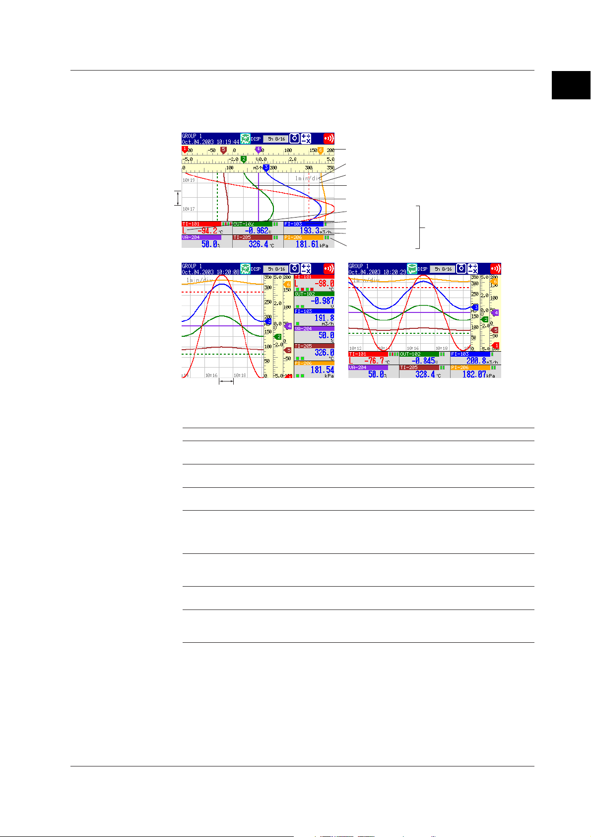
Trend Display
Displays the waveform of the measured and computed data. The direction of the
waveform display can be set to horizontal or vertical.
Trend (Vertical)
Scale
Display update rate (Time/div)
Grid
1div
Trend (Horizontal, Type1) Trend (Horizontal, Type2)
Message (mark, time, message)
Trip line
Alarm type
Tag/channel no.
Unit
Alarm mark
Numerical
display section
1
Explanation of Functions
1div
Displayed Information
The following Information can be displayed.
Information Description
All channel display Waveforms of all channels that were set to display the trend are
Displayed color of waveforms The displayed color of waveforms can be specified for each
Thickness of waveform lines You can select from 1, 2, or 3 dots. The specified thickness of
Trip line display Displays a line to indicate a particular value of interest (trip line) for
Scale display A scale appropriate for the measured item can be displayed for
Grid The specified number of lines are displayed on the waveform
Turn ON/OFF the numerical The numerical display section can be turned ON or OFF.
display section If the numerical display section is turned OFF, the display shows
displayed on one trend screen.
channel. The color also applies to the bar graph.
waveform lines applies to all channels.
each group. You can select the thickness of the displayed line from
1, 2, or 3 dots. Up to four trip lines can be displayed on a single
group.
each channel. You can select whether or not to display the scale
for each channel.
display area.
only the waveform and the scale.
IM 04L20A01-01E
1-17
Page 29
1.4 Display Function
Display Update 15 s* 30 s* 1 min 2 min 5 min10 min 15 min 20 min 30 min 1 h 2 h 4 h 10 h
Rate (/div)
Speed of movement 2500 1250 625 312 156 78 42 31 21 10 5.2 2.6 1.0
of waveform
(approximate value, mm/h)
* for the FX103 only
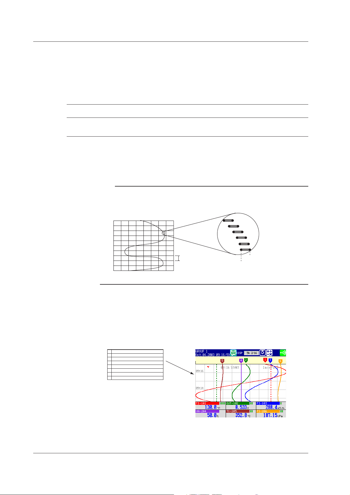
Updating the Waveform
One division along the time axis consists of 30 dots on the LCD. The displayed
waveform is updated at an interval corresponding to one dot. This interval is
determined by the time period corresponding to one division (referred to as the display
update rate). The relationship between the display update rate and the sampling
interval of displayed data is as follows:
Updating the Numerical Display
Numerical display is updated every second. However, when the scan interval on the
FX106/FX112 is 2 s, the update rate is also 2 s.
Note
The data displayed on the screen are a maximum and minimum values of the data that are
sampled at the scan interval, within the time period corresponding to one dot.
Displayed data of the waveform (when the display update rate is set to one minute)
}
2 s (1 dot)
1 division (30 dots)
=1 min.
Maximum value
Minimum value
When the display update rate is set to one minute,
the time period corresponding to one dot (the
sampling interval of displayed data) is 2 s.
Writing Messages
Messages specified by the user can be displayed at arbitrary points in time. For
example, by displaying a message when a certain operation is carried out, the point at
which the operation is carried out can be seen visually. Displayed messages are
saved.
Number of Messages: 8
Messages
START
1
PROCESS 2
2
3
4
5
6
7
8
Trend Screen
1-18
IM 04L20A01-01E
Page 30
1.4 Display Function
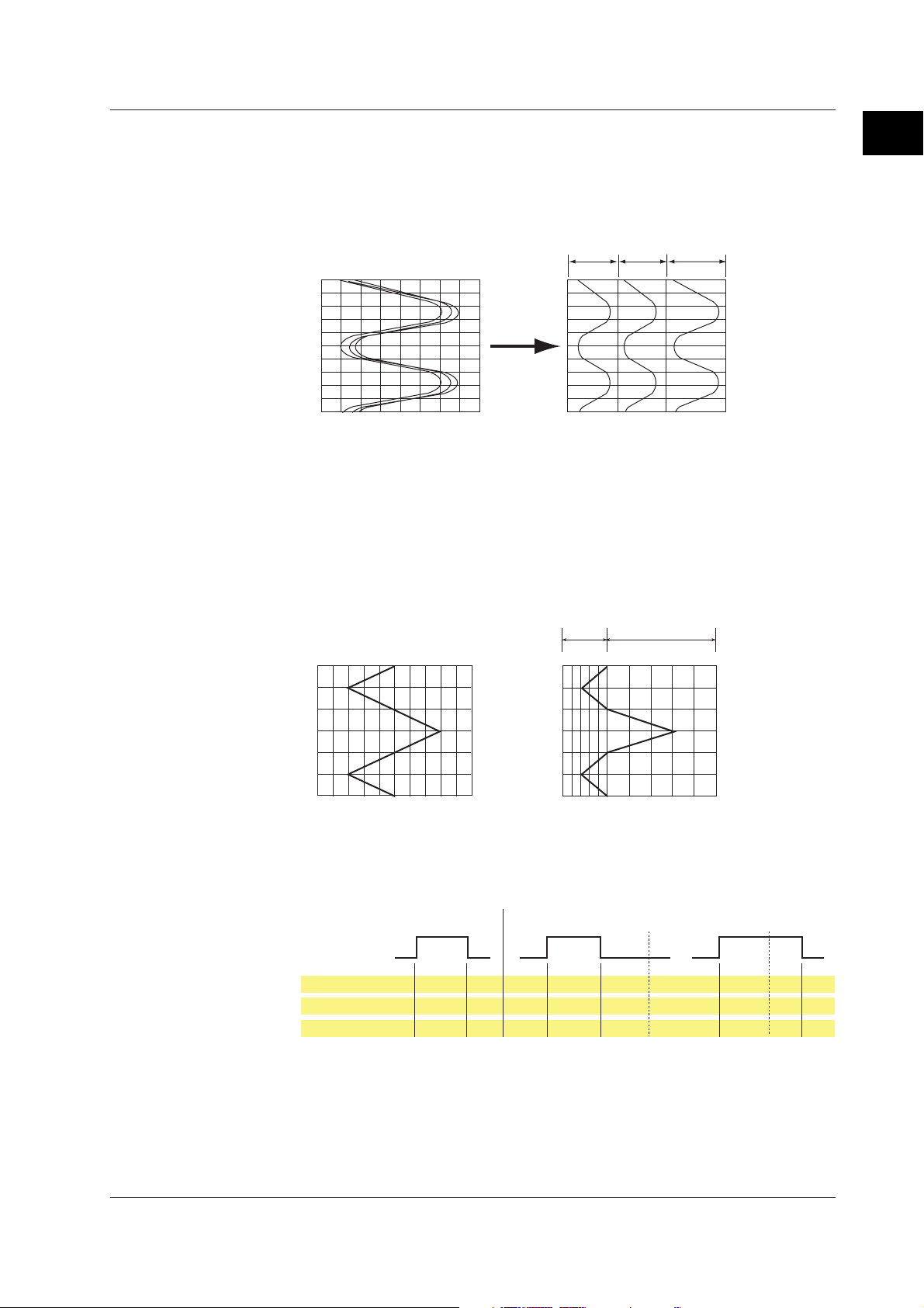
Zone Display
The display range (zone) can be set for each channel. In the example shown in the
figure below, channel 1 is displayed in the zone 0 to 30%, channel 2 in the zone 30 to
60%, and channel 3 in the zone 60 to 100%.
Normal display Zone display
0%
100%
Zone 1
30%0% 60%
Zone 3Zone 2
100%
CH3CH2CH1
Partial Expanded Display
By compressing a section of the display scale of the waveform, the remaining section
of is expanded. You specify a value on the display scale (boundary value) to be
moved to another position on the display scale (boundary value displacement
position). In the example shown below, 0 V (boundary value) is moved to the 30%
position of the display scale (boundary value displacement position). The section
below the boundary represents –6 V to 0 V and the section above the boundary
represents 0 V to 6 V.
Normal Display
% of full display span
0
Compressed portion
50
100
Partial Expanded Dispaly
0
Expanded portion
30
100
1
Explanation of Functions
IM 04L20A01-01E
–6V
0
6V
–6V
0
Measured valueMeasured value
6V
Alarm Indication
The indications of preset alarm marks vary depending on the hold/non-hold setting of
alarm indication as follows.
Non hold Hold
Occurrence
Alarm
Release
Brinks
Alarm mark
Alarm type
Measured value
Green Red RedGreen Green GreenGreen Green
None Red RedNone None None None None
Blue Red RedBlue Blue Blue Blue Blue
in red
Red None Red
Red Blue Red
For a description on the hold/non-hold setting of alarm indication, see section 1.3, “
Function
.”
Alarm ACK Alarm ACK
Brinks
in green
Brinks
in red
Alarm
1-19
Page 31

1.4 Display Function
Digital Display
The measured data are displayed using numerical values in large size.
Tag/channel no.
Measured value
Unit
Alarm mark
Updating of the Numerical Display
Numerical display is updated every second. However, when the scan interval on the
FX106/FX112 is 2 s, the update rate is also 2 s.
Note
• Numerical Display of Measurement Channels (Common to Trend, Digital, and Bar
Graph Displays)
When the measured values of measurement channels are over range (see below), the
measured values are indicated as “+Over” or “–Over.” If a burnout is detected on a channel
assigned to the burnout detection function, "Burnout" is displayed for the measured value.
Otherwise, a numerical value is displayed.
Over Range of Measurement Channels
• For DC voltage input, over range occurs when the measured value of the measurement
channel exceeds ±5% of the measurable range. For example, the measurable range
when the measurement range is 2 V is –2.000 to 2.000 V. If the measured value exceeds
2.200 V, + over range occurs; if the measured value falls below –2.200 V, – over range
occurs.
• For thermocouple or RTD input, over range occurs when the measured value exceeds
approximately ±10°C of the measurable range. For example, the measurable range when
the measurement range is R is 0.0 to 1760.0°C. If the measured value exceeds
approximately 1770.0°C, + over range occurs; if the measured value falls below
approximately –10.0°C, - over range occurs.
• Numerical display of computation channels (common to trend, digital, and bar graph
displays)
See section 1.6, “
Computation Function and Report Function (/M1, /PM1 Option)
.”
1-20
Alarm Indication
The indications of preset alarm marks vary depending on the hold/non-hold setting of
alarm indication as follows.
Non hold Hold
Occurrence
Alarm
Release
Alarm mark
Measured value
For a description on the hold/non-hold setting of alarm indication, see section 1.3, “
Function
Green Red RedGreen Green GreenGreen Green
Blue Red RedBlue Blue Blue Blue Blue
.”
Brinks
in red
Red Blue Red
Alarm ACK Alarm ACK
Brinks
in green
Brinks
in red
IM 04L20A01-01E
Alarm
Page 32
1.4 Display Function
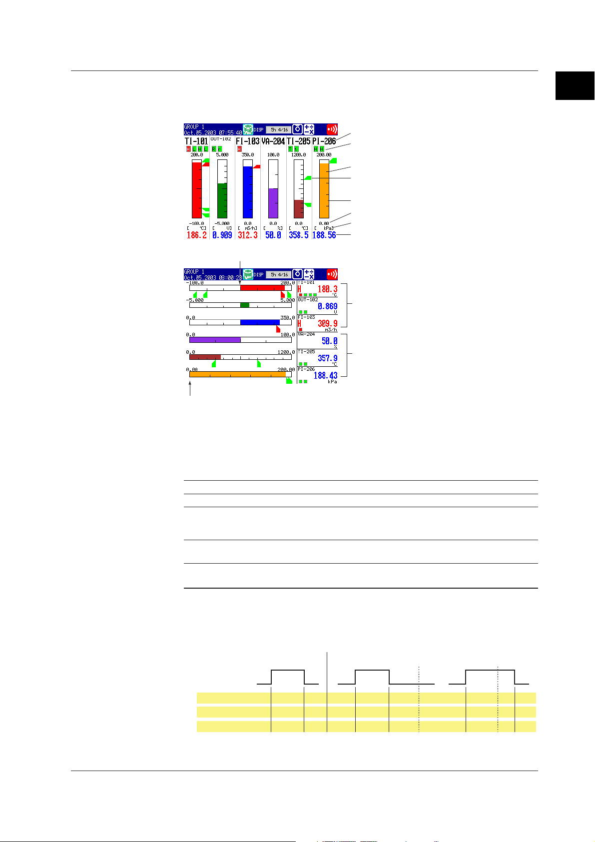
Bar Graph Display
The measured/computed data are displayed using bar graphs.
Bar Graph (Horizontal)
Tag/channel no.
Alarm mark
Upper limit of span
Scale
Alarm point mark
Bar graph
Lower limit of span
Unit
Measured value
Bar Graph (Vertical)
Center
Bar graph base position: [Center]
Bar graph base position: [Normal]
1
Explanation of Functions
Left end
Updating of the Numerical Display
Numerical display is updated every second. However, when the scan interval on the
FX106/FX112 is 2 s, the update rate is also 2 s.
Displayed Information
The following Information can be displayed.
Information Description
Display direction The bar graph can be displayed vertically or horizontally.
Reference position When the bar graph is displayed horizontally, the starting point of the bar
Display color The displayed color of bar graphs can be specified for each channel. The
Scale display Main scale marks are displayed for each channel. This is common with the
(reference position) can be set to standard (Left or right end of the scale,
whichever the value is smaller) or the center.
display color is common to the trend display color.
number of scale divisions of the trend display.
Alarm Indication
The indications of preset alarm marks vary depending on the hold/non-hold setting of
alarm indication as follows.
Non hold Hold
Occurrence
Alarm
Release
Alarm mark
Alarm piont mark
Measured value
For a description on the hold/non-hold setting of alarm indication, see section 1.3, “
Function
Green Red RedGreen Green GreenGreen Green
Green Red RedGreen Green Green
Blue Red RedBlue Blue Blue Blue Blue
.”
Brinks
in red
Red Green Red
Red Blue Red
Alarm ACK Alarm ACK
Brinks
in green
Brinks
in red
None None
Alarm
IM 04L20A01-01E
1-21
Page 33

1.4 Display Function
Overview Display
Displays alarm conditions of all channels.
You can move the cursor to select a channel and display the trend or bar graph of the
group containing the selected channel.
Cursor (white frame)
Channel No. or tag name
Alarm type
Area of channels on which an
alarm is occurring is indicated
Area of channels on which an
alarm is not occurring is
indicated in green
in red
Updating the Numerical Display
Numerical display is updated every second. However, when the scan interval on the
FX106/FX112 is 2 s, the update rate is also 2 s.
Alarm Indication
The display in the channel display area and channel no./tag name when an alarm
occurs on any of the channels varies depending on the hold/non-hold setting of alarm
indication as follows.
Occurrence
Alarm
Release
Channel No.
(tag)
Chammel area
Alarm type
Measured value
Non hold
Brinks
Black White
Green Red RedGreen Green GreenGreen Green
None White None None None None None
Black White Black Black Black Black Black
Black Black Black Black Black
in white
Brinks
in black
Red
White None White
White Black White
Hold
Alarm ACK Alarm ACK
Brinks
in white
Green
Red
White
White
White
1-22
For a description on the hold/non-hold setting of alarm indication, see section 1.3, “
Function
.”
IM 04L20A01-01E
Alarm
Page 34

1.4 Display Function
Alarm Summary
A list of the most recent alarms can be displayed.
• Up to 120 incidents can be displayed.
• By selecting an alarm from the list using arrow keys, the historical trend of the display
data or event data containing the alarm can be recalled.
Number of the alarm information displayed at the bottom of the screen
Number of the alarm information in the internal memory
Tag/Channel no.
Mark (indicates the alarm status)
Cursor (selects the alarm information)
Alarm No. (1, 2, 3, 4) /Type (H, L, h, l, R, r, T, t)
Date & Time (alarm occurred)
Date & Time (alarm was released)
Historical trend of the data containing
the selected alarm information
1
Explanation of Functions
Alarm Mark Indication
The mark indication varies depending on the hold/non-hold setting of alarm indication
as follows.
Non hold Hold
Occurrence
Alarm
Release
Mark
For a description on the historical trend display, see page 1-26.
For a description on the hold/non-hold setting of alarm indication, see section 1.3, “
Function
.”
Red RedGreen Green-- -Green
Brinks
in red
Alarm ACK Alarm ACK
Brinks
in green
-: Alarm information is not displayed.
Brinks
in red
Alarm
IM 04L20A01-01E
1-23
Page 35

1.4 Display Function
Message Summary
The messages and the times when they were entered are displayed in a list.
• Up to 100 messages can be displayed.
• By selecting a message from the list using arrow keys, the historical trend of the
display data or event data containing the message can be recalled.
Number of the message displayed at the bottom of the screen
Number of the messages in the internal memory
Message/Date and time the message was written
User name who wrote the message
is displayed if you use the key login
function.
Cursor (selects a message)
Historical trend of the data containing
the selected message
For a description on the historical trend display, see page 1-26.
1-24
IM 04L20A01-01E
Page 36

1.4 Display Function
Memory Summary
The information pertaining to the display data and event data in the internal memory is
displayed.
• By selecting the display data or event data using the arrow keys, the historical trend
display can be recalled.
• The number of manual sampled data, TLOG data (/M1, /PM1 option), and report data
(/M1, /PM1 option) residing in the internal memory are displayed.
• For models that have the alarm output relays (/A1, /A2, /A3 option), the ON/OFF state
of the relays are also listed.
Number of data sets in the internal memory
The maximum number of data sets the internal memory can hold
Date and time the last data were acquired
Status of alarm output relays
Red: Activated
Green: Released
Data type
(display data or event data)
Date and time
data acquisition
started
Cursor
(selects a file)
Manual sampled data
TLOG data
Report data
Date and time data acquisition ended
Sampling status
Number of samplings
Historical trend of the selected data
1
Explanation of Functions
For a description on display data and event data, see section 1.5.
For a description on the historical trend display, see page 1-26.
Report Data (/M1, /PM1 Option)
Report data residing in the internal memory can be displayed.
Channel no./tag
IM 04L20A01-01E
The index number of the report data currently displayed
The number of report data sets in the internal memory
Report type
Date and time the report started
Date and time the report was created
Status of data
Unit
For a description on report function, see section 1.6.
Average (or instantaneous), maximum,
minimum, and sum values
1-25
Page 37

1.4 Display Function
Historical Trend
The waveform of the measured data in the internal memory or the external storage
medium can be displayed. This function is called “Historical trend.”
Methods Used to Display the Historical Trend
The following four methods are available in displaying the historical trend of the
display data or event data in the internal memory:
• Display from the alarm summary. For the operating procedure, see section 5.3.
• Display from the message summary. For the operating procedure, see section 5.3.
• Display from the memory summary. For the operating procedure, see section 5.3.
• Recall from the screen menu. For the operating procedure, see section 5.4.
You can display the historical trend of the display data or event data on the external
storage medium. For the operating procedure, see section 7.6.
Information Displayed on the Historical Trend
Alarms and scales are not displayed on the historical trend display.
The background color of the historical trend is either black or white,
opposite of the background color displayed for the current trend.
Time axis
Zoom factor of the time axis
Screen switch display
Display reference position
(The most recent data locates.)
Date and time at the display reference position
Trip line
Date and time at the display end position
Tag /C hannel no.
Unit
Measured/computed value
(maximum and minimum
value at the display
reference position)
Measured/computed value
(maximum and minimum
value over the entire
display range)
Operation on the Historical Trend
The following operations can be carried out.
• The waveform can be scrolled along the time axis using the the arrow keys.
• The time axis can be expanded or reduced.
• You can display all the data points of the file displayed on the historical trend display
in a section of the screen (all data display) and specify the data that positions to the
reference position using a cursor.
Date and time at the cursor position
Cursor
All data display
1-26
IM 04L20A01-01E
Page 38

1.4 Display Function
• The information of the data being displayed on the historical trend can be displayed.
When the login function is disabled When the login function is enabled
File Name (Data Kind): File name and data type (display data or event data)
Serial No.: Serial number of the FX100 that acquired the data
Start Time, End Time: Time at which data acquisition is started/stopped
Start User Name, Stop User Name: Name of the user who carried out the operation
(user name is displayed only when the key login function is used).
Half Screen Display (Only When Displaying the Historical Trend of the Display
Data)
Using up and down arrow keys, you can have a half of the display show the historical
data of the display data and the other half show the display data currently being
measured.
1
Explanation of Functions
Setting the Display Condition of the LCD
The following display conditions of the LCD can be configured.
Display Attribute Setting
Background color of The background color of the display can be set to white or black. The initial
the operation display setting of the control operation display is [Black]; the initial setting of the
measurement operation display is [White].
LCD brightness The brightness of the LCD can be set between eight levels. The initial setting is [2].
Backlight saver The lifetime of the LCD backlight can be extended by automatically dimming
the light when there is no key operation for a certain amount of time. The
display returns to the original brightness with a key operation or an alarm
occurrence. The initial setting is set so that the backlight saver is disabled.
Current ternd
Historical trend
Current channel information
IM 04L20A01-01E
1-27
Page 39

1.5 Data Storage Function
This section describes the types of data that can be created and how to save them.
Data Type and Data File
Data types and corresponding files are as follows:
Type Content
Display data • Waveform data that have been sampled at a specified sampling interval
Event data • The measured/computed data are acquired at the specified sampling
Manual sampled data • Every time a key that executes manual sampling is pressed, the
TLOG data (option) • The measured/computed data of all channels is acquired to the internal
Report data (option) • Consists of hourly, daily, weekly, and monthly reports. Data are
Setup data • The setup data of the FX100
Screen image data • The screen image displayed on the FX100.
and displayed on the trend display.
• The maximum and minimum values from measured/computed data
within the sampling intervals are held.
•A header string can be written into the display data file (a character
string that is common to all data files).
• Alarm and message information is held.
• Data format: Binary format (undisclosed)
• File name: Mddhhmma.DDS
interval. There is a mode in which the data acquisition is started when a
trigger occurs or another mode in which the data is acquired
continuously.
• The header string can be written into the event data file (a character
string that is common to all data files).
• Alarm and message information is held.
• Data format: Binary format (undisclosed)
• File name: Mddhhmma.DEV
measured/computed data of all channels at that point are acquired.
• Up to 50 samples of data can be stored in the internal memory.
• The header string can be written into the manual sampled data file (a
character string that is common to all data files).
• Data format: ASCII format
• File name: Mddhhmma.DMN
memory at the end of every interval period a timer specifies.
• Up to 400 data sets can be stored in the internal memory.
• The header string can be written into the TLOG data file (a character
string that is common to all data files).
• Data format: Binary format (undisclosed)
• File name: Mddhhmma.DTG
computed at intervals depending on the report type (one hour for hourly
report, one day for daily report, etc.). Data are added to the internal
memory at the end of every interval period.
• Up to 40 reports can be stored in the internal memory.
• Each report file can contain up to 12 measured/computed channels of
report data.
• The header string can be written into the report data file (a character
string that is common to all data files).
• Data format: ASCII format
• File name:
Hourly report: Mddhhmma.DHR, Daily report: Mddhhmma.DDR, Weekly
report: Mddhhmma.DWR, Monthly report: Mddhhmma.DMR
• File name: Up to eight alphanumeric characters, Extension: .PNL
• File name: Mddhhmma.PNG
1-28
For information on using each type of data, see appendix 4, “
on the FX100 and Their Uses
.”
Types of Data Created
IM 04L20A01-01E
Page 40

1.5 Data Storage Function
File Name
• Mddhhmm denotes the date and time.
Mddhhmm of setup data and screen image data is the date and time the file was
created.
Mddhhmm of other data is the date and time the first data was sampled.
M: Month (1 to 9, X (October), Y (November), Z (December), dd: day, hh: hour,
mm: minute
• “a” denotes the last digit of the year (0 to 9).
However, “a” becomes a sequence number for the following case. It takes a value
between A and Z.
For example, if the acquisition of the display data is started and stopped, and started
again within 1 minute by pressing the START key, the two file names are the same up
to Mddhhmm (month, day, hour, and minute). In this case, the second file is assigned
the sequence number A.
Example:
70112563.DDS
7011256A.DDS
Two display data files which sampling started on July 1st, 2003 at 12:56.
File Creation
The display data, event data, manual sampled data, TLOG data (/M, /PM1 option),
and report data (/M, /PM1 option) are temporarily written to the internal memory. Data
files are created when the data in the internal memory is saved to the external storage
medium.
1
Explanation of Functions
Note
A backup should be made of the data on the external storage medium.
IM 04L20A01-01E
1-29
Page 41
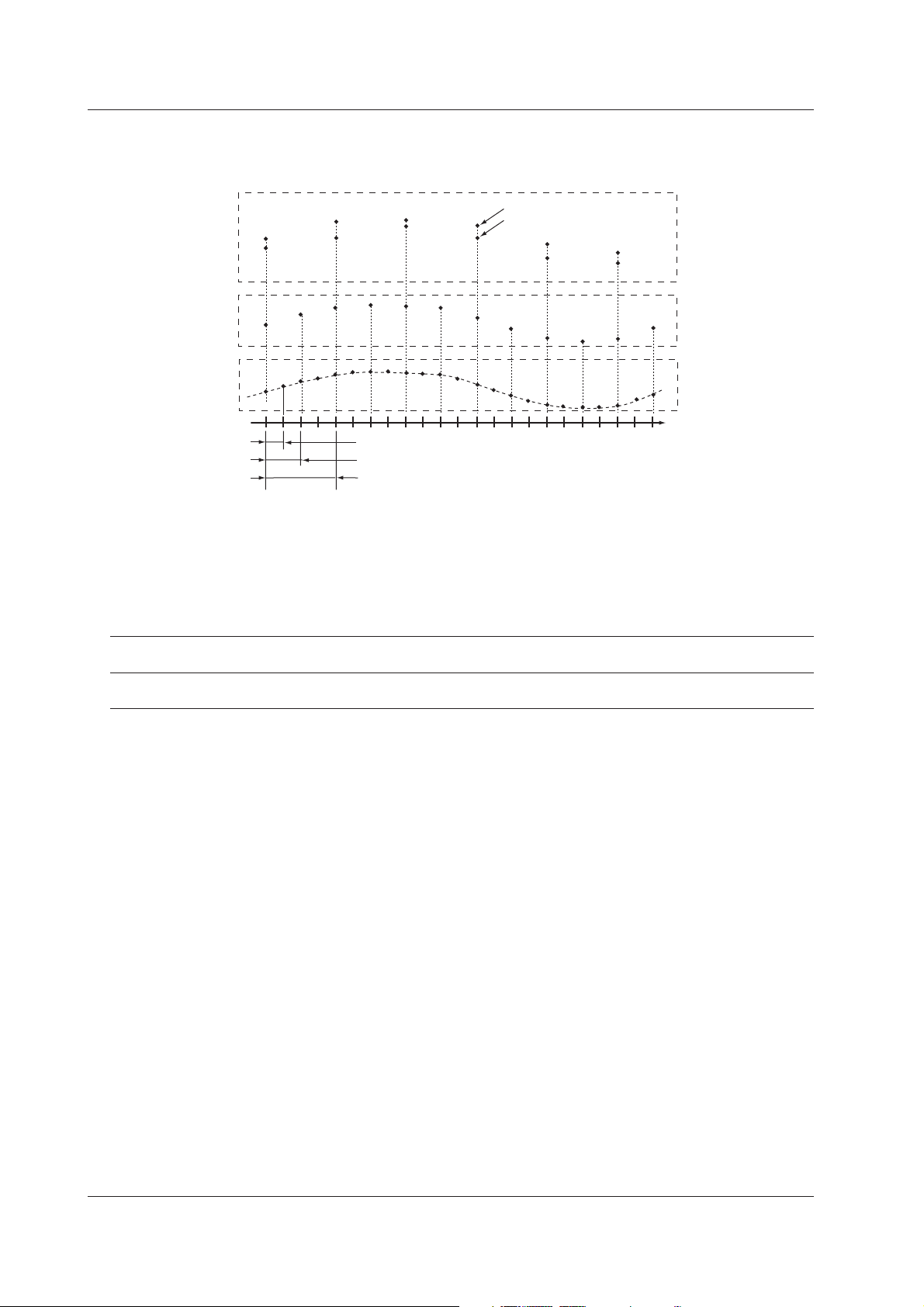
1.5 Data Storage Function
Display Data and Event Data
The measured/computed data are first acquired to the FX100’s internal memory as two
types of data, display data and event data.
• Display Data
Display data are used to display waveforms on the FX100’s screen. The sampling
interval of display data is the time period corresponding to one dot on the screen.
This interval is determined by the display update rate. The relationship between the
display update rate and the sampling interval of display data is as follows:
Maximum value
Minimum value
Time
Scan interval
Sampling inteval of event data
Sampling inteval of display data (time corresponding to
one dot on the screen)
Display data
Event data
Measured/computed
data at scan intervals
Display Update 15 s* 30 s* 1 min 2 min 5 min 10 min 15 min 20 min 30 min 1 h 2 h 4 h 10 h
Rate (/div)
Sampling interval 0.5 1 2 4 10 20 30 40 60 120 240 480 1200
of display data (s)
* for the FX103 only
Display data consists of maximum and minimum values of the measured or computed
data sampled at the scan interval within the time period corresponding to one dot on
the time axis on the screen. Display data can be likened to the conventional
recording on the chart sheet and are useful for long-term observations.
See page 1-18 for the display update rate.
• Event Data
Event data is the measured/computed data at specified sampling intervals. The
sampling interval can be selected from the selections below. You cannot specify a
sampling interval that is faster than the scan interval.
FX103: 250 ms, 500 ms, 1 s, 2 s, 5 s, 10 s, 30 s, 60 s, 120 s, 300 s, and 600 s
FX106/FX112:1 s, 2 s, 5 s, 10 s, 30 s, 60 s, 120 s, 300 s, and 600 s
By setting the sampling interval equal to the scan interval, all measured or computed
data sampled at the scan interval can be saved. In addition, the event data generated
when an event occurs (an alarm, for example) can also be saved. This is useful when
you wish to observe the measured/computed data in detail.
1-30
IM 04L20A01-01E
Page 42

1.5 Data Storage Function
Specifying the Data to Be Acquired
Specify the type of data to be acquired depending on the application. Several
examples are shown below. Please use them as references.
Example 1: Continuously record the waveform data as in the conventional
chart-type recorders.
Select “display data only.”
Example 2: Continuously record the waveform data and when an alarm occurs,
record detailed data around the alarm incident.
Select “display data and event data.” For the event data, select “Trigger” or
“Rotate” for the mode. Specify the trigger used to start the event data acquisition
and the time period during which to acquire the data (event data file size).
Example 3: Continuously record detailed data.
Select “even data only.” Select “Free” for the mode.
Example 4: Recording is not necessary under normal circumstances. Only
record detailed data around the alarm incident.
Select “event data only.” Select “Trigger” or “Rotate” for the mode. Specify the
trigger used to start the event data acquisition and the time period during which to
acquire the data.
1
Explanation of Functions
IM 04L20A01-01E 1-31
Page 43

1.5 Data Storage Function
Acquiring Data to the Internal Memory (Display Data and Event Data)
Combination of Data Types to Be Acquired
Select “display data only,” “display data and event data,” or “event data only.”
Internal Memory Capacity
The capacity of the internal memory for acquiring display data and event data is 1.2
MB. When the measured/computed data are saved as both display data and event
data, 0.9 MB is used to save display data and 0.3 MB is used to save event data.
FX100
Internal memory
Display data only
1.2MB
Event data only Display data and event data
1.2MB
0.9MB
0.3MB
Display data
Event data
Display data Event data
Channels for Saving the Display Data / Event Data
You can specify the channels to save the display data or event data from the
measurement and computation channels (/M1, /PM1 option). By default, the data of
all measurement/computation channels is set to be saved.
Data Acquisition (Display Data)
Data acquisition starts when the START key is pressed and stops when the STOP
key is pressed. The display data are overwritten when the display data storage area
in the internal memory becomes full, or the number of files* exceeds 16.
* The number of display data files
During manual save, a file is created for each data write operation (a set of start and stop
operations). During auto save, a file is created every auto save interval and at every
specified date/time.
Note
• The display data in the internal memory can be confirmed with the memory summary. See
section 5.3.
• When a power disruption occurs the file is closed.
Data Acquisition (Event Data)
The operation differs from the mode you specified. There are three modes in data
acquisition, [Free], [Trigger], and [Rotate]. [Free] mode can be set when acquiring the
event data only.
Mode Description
Free Data acquisition is started by pressing the START key. The operation is stopped
by pressing the STOP key. When the storage area of the internal memory
becomes full, or the number of files* in the internal memory exceeds 16, it is
overwritten.
* The number of event data files
During manual save, a file is created for each data write operation (start and
stop operations). During auto save, a file is created every specified interval
(data length) and at every specified date/time.
1-32
IM 04L20A01-01E
Page 44
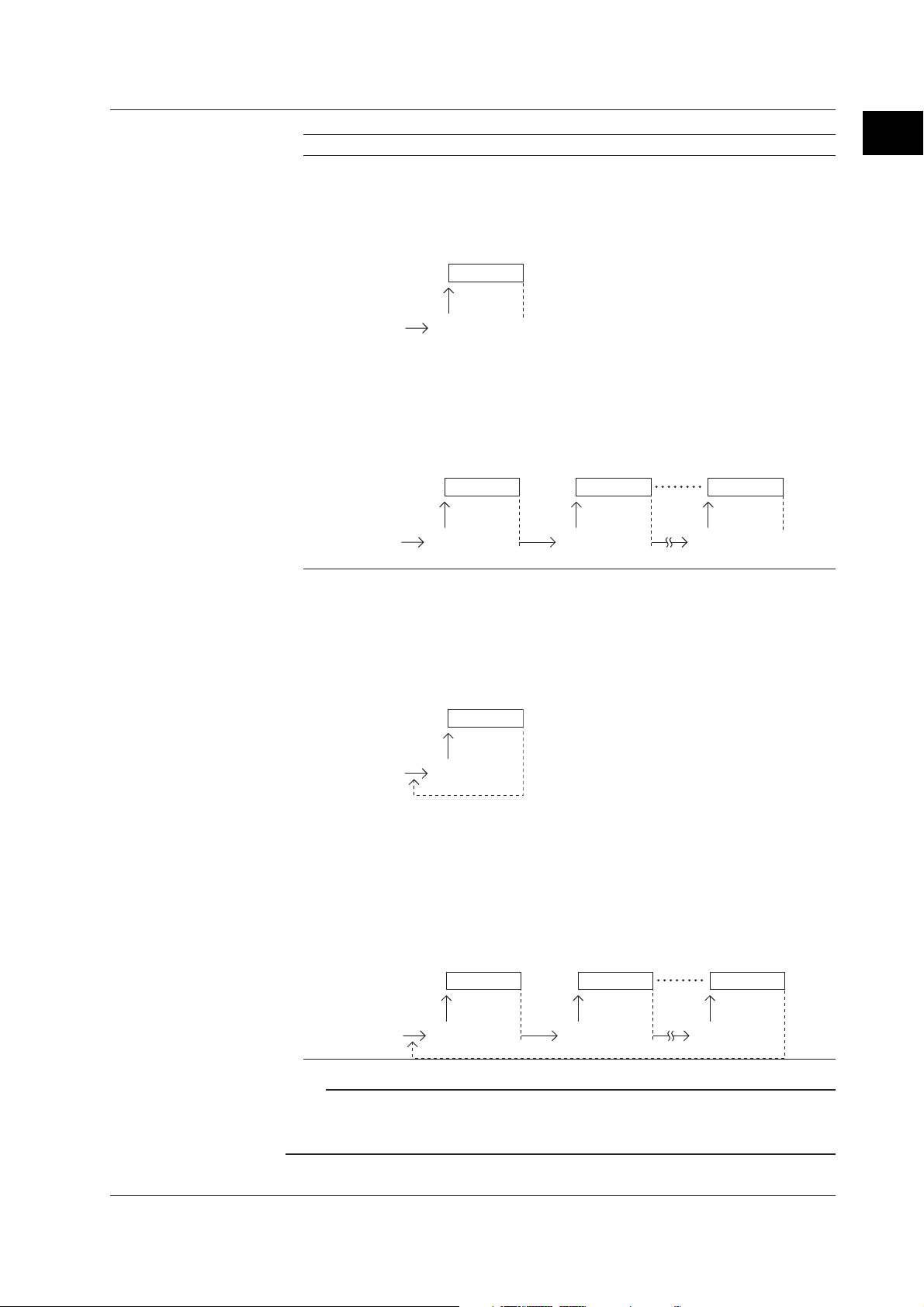
1.5 Data Storage Function
Mode Description
Trigger When the internal memory is not divided into blocks:
One event data file is created in the internal memory.
Press the START key to enter the trigger wait state.
After the trigger is activated, data are acquired for the specified time (data length)
and the operation is stopped. At this point, the acquisition does not start even if
the trigger is activated.
Data acquisition
Trigger wait
Trigger activated
Stop
When the internal memory is divided into blocks:
An event data file each in the block is created.
Press the START key to enter the trigger wait state.
After the trigger is activated, data are acquired for the specified time (data length)
and the operation is stopped. When the trigger is activated again, data are
acquired and stored to the next block. When all blocks are full, no more
acquisition takes place.
First block
Data acquisition
Trigger wait Trigger wait Trigger wait
Trigger activated Trigger activated Trigger activated
Second block
Data acquisition
Data acquisition
Rotate When the internal memory is not divided into blocks:
One event data file is created in the internal memory.
Press the START key to enter the trigger wait state.
After the trigger is activated, data are acquired for the specified time (data length,
see section 8.11) and the operation is stopped. Data are overwritten when the
trigger is activated again. Every time the trigger is activated during the trigger
wait state, data are overwritten. Press the STOP key to terminate data
acquisition.
1
Explanation of Functions
Last block
Stop
Data acquisition
Trigger wait
Trigger activated
When the internal memory is divided into blocks:
An event data file each in the blocks is created.
Press the START key to enter the trigger wait state.
After the trigger is activated, data are acquired for the specified time (data length,
see section 8.11) and the operation is stopped. When the trigger is activated
again, data are acquired and stored to the next block. When all blocks are full
and the trigger is activated, data are overwritten to the first block. Every time the
trigger is activated during the trigger wait state, data are overwritten to the next
block. Press the STOP key to terminate data acquisition.
First block
Data acquisition
Trigger wait Trigger wait Trigger wait
Trigger activated Trigger activated Trigger activated
Second block
Data acquisition
Last block
Data acquisition
Note
• The event data in the internal memory can be confirmed with the memory summary. See
section 1.4 .
• When a power failure occurs, the event data file in the internal memory is closed as one file.
IM 04L20A01-01E 1-33
Page 45

1.5 Data Storage Function
Pretrigger for the Event Data
Pretrigger is applied to the event data with [Trigger] or [Rotate] modes.
You can have event data before the trigger point be stored.
It is specified in terms of a percentage of the data length (0, 5, 25, 50, 75, 95, 100%).
If 0% is selected, all data are after the trigger point. The initial setting is 0%.
Trigger Type for the Event Data
When [Trigger] or [Rotate] is selected, the trigger type is selected by turning each type
of trigger ON/OFF. The triggers operate in an OR fashion: the trigger is activated
when any of the conditions that are turned ON are satisfied.
Type Description
Key trigger The trigger condition is satisfied when the FUNC key > [Trigger] soft key or the
USER key (only when the “trigger” function is assigned to the USER key) is
pressed.
External trigger The trigger condition is satisfied when the external contact specified by remote
control function is turned ON.
Alarm trigger The trigger condition is satisfied when any of the alarms occur.
Estimate of the Number of Data That Can Be Written to the Internal Memory, and
the Time Required to Do So
See appendix 1, “
Memory
.”
Time Estimate for Writing Display/Event Data to the Internal
1-34
IM 04L20A01-01E
Page 46

1.5 Data Storage Function
Acquiring Data to the Internal Memory (Other Data)
Manual Sampled Data
Every time a given key operation is carried out, all measured/computed data at that
point is acquired to the internal memory except for measurement channels that are
skipped and computation channels that are turned OFF.
Manual sample operation is executed.
The measured/computed data of all channels are acquired to the
internal memory.
• Up to 50 data sets can be stored in the internal memory. When this number is
exceeded, data are overwritten from the oldest data.
Note
The number of manual sampled data in the internal memory can be confirmed with the
memory summary. See section 1.4 .
TLOG Data (/M1, /PM1 Option)
All the measured/computed data of all channels can be acquired to the internal
memory at the preset interval. However, this excludes measurement channels that
are skipped and computation channels that are turned OFF.
• TLOG data is acquired from the time the computation is started till the computation
is stopped.
• TLOG data is acquired at each time interval set by timers and when the
computation is stopped.
Start
computation
T1
t1 t2 tn
Interval time set by the timer
computation
tn+1
Time
Stop
T2
1
Explanation of Functions
Time
The measured/computed data of all channels are acquired to the
internal memory.
• Up to 400 data sets can be stored in the internal memory. When this number is
exceeded, data are overwritten from the oldest data.
Note
• Up to 16 blocks (number of computation start-and-stop operations) can be created in the
internal memory. When the number of blocks in the internal memory exceeds 16, TLOG data
is overwritten even if the number of data sets is less than 400.
• The number of TLOG data sets in the internal memory can be confirmed with the memory
summary. See section 1.4 .
IM 04L20A01-01E 1-35
Page 47

1.5 Data Storage Function
Report Data (/M1, /PM1 Option)
The average or instantaneous value, and maximum, minimum, and sum can be
computed for the specified channels at the preset interval, and the result can be
acquired to the internal memory.
• Reports are created from the time the data acquisition is started till the data
acquisition is stopped.
• Reports are created at each time interval (one hour for hourly report, one day for
daily report, etc) and when the data acquisition is stopped.
• You can select report type from hourly, daily, hourly and daily, daily and weekly, or
daily and monthly.
Start
writing data to
internal memory
T1
The average (or instantaneous data), maximum, minimum, and sum for the
specified channels stored to the internal memory.
The interval time for the report creation (1 hour, 1 day, 1week, or 1 month)
Stop writing data
T2
t1 t2 tn
tn+1
Time
• Up to 40 data sets can be stored in the internal memory. When this number is
exceeded, data are overwritten from the oldest data.
For “hourly only”, this constitutes 40 minutes of report data. For “daily+monthly”,
this constitutes 39 daily reports and one monthly report or 38 daily reports and two
monthly reports.
Note
The number of report data sets in the internal memory can be confirmed with the memory
summary. See section 1.4 .
1-36
IM 04L20A01-01E
Page 48

1.5 Data Storage Function
Saving Data to the External Storage Medium (for Models with External Storage Drive)
Type of Storage Medium
The measured/computed data in the internal memory can be saved to the following
external storage media.
• Floppy disk (1.44 MB)
• CF memory card (32 MB to 512 MB)
Note
• Use an external storage medium formatted to “FDISK 1 partition (hard disk format).”
• If a memory card larger than 32 MB is formatted using Windows XP, FAT32 is selected by
default. The FX100 cannot use memory cards formatted to FAT32. When formatting a
memory card on Windows XP, select FAT for the file system.
Two Saving Methods
There are two methods in which the data are saved to the external storage medium,
manual save and auto save.
Manual Save
When saving the data residing in the internal memory to the external storage medium,
insert the storage medium into the drive and carry out a given key operation. You can
specify whether to save the entire data in the memory or only the data that have not
been saved to the storage medium beforehand.
Be sure to save data to a storage medium before it is overwritten. Check the
remaining space in the internal memory and save data.
1
Explanation of Functions
Auto Save
The external storage medium is placed in the drive at all times. Data saving to the
external storage medium is done automatically.
• Display data
The display data in the internal memory is saved automatically to the external
storage medium according to the timing shown below.
•At specified intervals
You ca select an interval (auto save interval) form 10 minutes to 31 days.
* The selections vary depending on the number of channels of data that is saved and the
sampling interval.
• Specified time
You can specify a time to save the data as follows. This operation is called
“data saving through memory timeup .”
• Every hour on the hour
• Specified hour on the hour every day
• Specified hour on the hour on the specified day every week
• Specified hour on the hour on the specified day every month
• When the acquisition to the memory is stopped
• When a given key operation is carried out to save data (see page 1-39.)
You can save data using a key operation when necessary.
*
IM 04L20A01-01E 1-37
Page 49

1.5 Data Storage Function
Examples of Data Save Operation to the External Storage Medium (During
Auto Save)
Example 1
Auto save interval or data length: 1 day
Date and time when data is saved to the external storage medium: Not used
After starting at 13:10, data is saved every 24 hours after (at 13:10 everyday).
7/19 13:10 7/20 13:10 7/21 13:10 7/22 13:10
Start
Example 2
Auto save interval or data length: 1 day
Date and time when data is saved to the external storage medium: 0 hour every day.
After starting at 13:10 on July 19th, data is saved at 0 hour on July 20th and then every
day after and at 0 hour every day (the same time for both in this example).
7/19 13:10 7/20 0:00 7/21 0:00 7/22 0:00
Start
Example 3
Auto save interval or data length: 12 hours
Date and time when data is saved to the external storage medium: 0 hour every day.
After starting at 13:10 on July 19th, data is saved at 0 hour on July 20th and then every
12 hours after and at 0 hour every day (0 hour occurs at the same time as the 12 hour timing).
7/19 13:10 7/20 0:00 12:00 12:00 12:007/21 0:00 7/22 0:00
Start
Example 4
Auto save interval or data length: 2 day
Date and time when data is saved to the external storage medium: 0 hour every day.
After starting at 13:10 on July 19th, data is saved at 0 hour on July 20th and then every 2 days
after and at 0 hour every day (the 2-day timing occurs at the same time as 0 hour).
7/19 13:10 7/20 0:00 7/21 0:00 7/22 0:00
Saved to the external storage medium
Saved to the external storage medium
Saved to the external storage medium
Start
Saved to the external storage medium
Note
If the saving of the data to the external storage medium is not complete due to reasons such
as insufficient free space, the next time data is saved to the external storage medium,
unsaved data is also saved.
• Event data (during [Free] mode)
The event data in the internal memory is saved automatically to the external
storage medium according to the timing shown below. For the saving operations,
see examples of data save operation for display data.
•At specified intervals
You ca select an interval (data length) from 3 minutes to 31 days.
* The selections vary depending on the number of channels of data that is saved and the
sampling interval.
• Specified time
You can specify a time to save the data as follows. This operation is called
“data saving through memory timeup.”
• Every hour on the hour
• Specified hour on the hour every day
• Specified hour on the hour on the specified day every week
• Specified hour on the hour on the specified day every month
*
1-38
IM 04L20A01-01E
Page 50

1.5 Data Storage Function
• When the acquisition to the memory is stopped
• When a given key operation is carried out to save data (see below.)
• Event data (during [Trigger] mode or [Rotate] mode)
• After acquiring the data to the internal memory over the specified period (data
length)
• When the acquisition to the memory is stopped
The following figure shows the operation when the acquisition area in the internal
memory is divided using the trigger mode.
Data save to the external storage medium
First block
Data acquisition
Trigger wait Trigger wait Trigger wait
Trigger activated Trigger activated Trigger activated
Second block Last block
Data acquisition
Data acquisition
Stop
Saving Data Using FUNC Key Operation (During Auto Save)
Through FUNC key operation, display data/event data can be saved to the external
storage medium at an arbitrary time during data acquisition. For the operating
procedure, see section 7.3 .
Below is the behavior of the FX100 when this operation is executed.
• When saving data at auto save intervals (display data) or data length (event
data)
Saving of the data is repeated at auto save intervals or every data length from the
point when data is saved through key operation.
Example: When auto save interval or data length is set to 1 hour
Data saved through key operation.
1
Explanation of Functions
Save to the external
storage medium.
11:20
The data here is saved.
Note
The save operation using the auto save interval or data length is executed by counting the
auto save interval or data length from the last time the data was saved.
• When saving data at specified times
The operation continues without change after saving the data through key operation.
Example: When data is saved every hour on the hour
Start
13:10 14:00 15:00 16:00 17:00
Save to the external
storage medium.
15:25 Data saved through key operation.
Time
This data
is saved.
This data
is saved.
Time10:00 11:00 12:0012:20 13:20
IM 04L20A01-01E 1-39
Page 51

5
3
y
d
d
.
1.5 Data Storage Function
• Manual sampled data
The first time manual sample is executed, a manual sampled data file is created on
the external storage medium. The data are appended to this file for each successive
manual sample operation.
Note
When auto save is selected and there is no medium in the drive at the time when manual
sample is executed, all unsaved data are saved the first time when manual sample is
executed, after the storage medium is reinserted into the drive.
• TLOG data (/M1, /PM1 option)
The first time TLOG data is acquired, a TLOG data file is created on the external
storage medium. The data are appended to this file at each time interval. When the
number of TLOG data sets exceeds 400, a new file is created.
Note
When auto save is selected and there is no medium in the drive at the time when data are
supposed to be saved, all unsaved data are saved the first time when the interval time
expires after the storage medium is reinserted into the drive.
• Report data (/M1, /PM1 option)
The first time report data is created, a report data file is created on the external
storage medium. A file is created for each type of report such as hourly, daily, weekly,
and monthly reports. The data are appended to this file at each time interval.
Dividing report files
The report files are divided at the following times.
• When data acquisition is stopped.
• For hourly reports
• When the 0:00 report is created every day.
• When the number of data sets in the file reaches 25.
• For daily reports
•When the report for the first day of the month is created every month
• When the number of data sets in the file reaches 32.
1-40
Note
When auto save is selected and there is no medium in the drive at the time when data are
supposed to be saved, all unsaved data are saved the first time when the interval time
expires after the storage medium is reinserted into the drive.
• FIFO (first in first out) method for the CF memory card
FIFO refers to a processing method in which the oldest files are deleted to make room
for new files when the external storage medium becomes full. FIFO can be specified
only if the external storage medium is a compact flash memory card (CF memory
card), and autos save mode is selected. The default is OFF.
Time
Data files
CF memor
34
car
The oldest file is overwritten by the newest fi
512
678
le
.......
.......
IM 04L20A01-01E
Page 52

1.5 Data Storage Function
• FIFO can be specified for files in the specified directory. FIFO cannot be specified for
read-only, system, or hidden files.
•In the following cases, the oldest files are deleted.
• When the amount of free space on the CF card after saving a data file falls below 1
MB.
•When the number of files in the directory is 1000 or more.
Note
The dates and times of manual sample files and report files are updated whenever new data
is added, meaning that they are less likely to be eligible for deletion. To release this condition
(only when the FIFO method is specified), manual sample files and report files are split when
they exceed 100 KB in size.
• If an error occurs with the CF memory card, the error indicator appears on the icon for
the external storage medium, and the memory end output relay (with the /F1 option)
becomes energized. To release this condition, replace or reformat the memory
medium.
Other Data that Can Be Saved
•Setup data
Setup data of the FX100 can be saved to the root directory of the external storage
medium.
1
Explanation of Functions
• Screen image data
You can save the screen image currently displayed on the FX100’s screen as a .png
format file.
Destination Directory Name
You can specify the name of the save destination directory on the external storage
medium (up to 8 alphanumeric characters. Initial value is [DATA0]) (see section 7.1 ).
* Display data, event data, manual sample data, TLOG data (/M1, /PM1 option), report data (/
File Header
You can write a header comment (up to 32 alphanumeric characters) to display data,
event data, manual sampled data, TLOG data (/M1, /PM1 option) and report data (/
M1, /PM1 option) files.
Saving Data via Ethernet
The display data, event data, report data, and screen image data can be automatically
transferred to an FTP server via Ethernet for storage. Conversely, the FX100 can
operate as an FTP server. In this case, the FX100 is accessed from a PC and the files
on the external storage medium can be retrieved for storage. For details on these
functions, see the ”
M1, /PM1 option), and screen image data files are saved to this directory.
FX100 Communication Interface User’s Manual
” (IM 04L20A01-17E).
IM 04L20A01-01E 1-41
Page 53

1.6 Computation Function and Report Function (/M1, /PM1 Option)
Computation Function
Equations can be written to computation channels by using the measured data or
computed data as variables. The result of the computation can be displayed or stored.
Computation is performed at the scan interval.
Computation Channels
You can use 12 computation channels, channel 31 to channel 42.
Types of Computations
In the table below, y represents the computed result. X and n generally represent the
measured data and a constant.
Type Description
Four arithmetical operations Addition (+), subtraction (–), multiplication ( ×), and division
(/)
Determines the power. y = X
SQR Determines the square root.
ABS Determines the absolute value.
LOG Determines the common logarithm. y = log10x
EXP Determines the exponent. y = e
Relational computation Determines <, ≤, >, ≥, =, ≠ of two elements and outputs “0”
or “1.”
Logical computation Determines the AND (logical product), OR (logical sum),
XOR (exclusive logical sum) of two elements, NOT
(negation) of an element and outputs “0” or “1.”
TLOG computation Determines the sum, maximum, minimum, average, and
maximum – minimum (P–P) values at specified time
intervals over the time interval. There are three timers used
to set the time interval. For detail, see page 1-45.
n
x
1-42
Data That Can Be Used in Equations
For TLOG computation, only measured and computed data can be used. For all other
computations, all types of data can be used.
• Measured data
The data are specified using channel numbers in computing equations. If scaling is in
effect, the scaled values are used in the computation.
• Computed data
The data are specified using channel numbers in computing equations.
• Constants (K01 to K30)
The values assigned to K01 to K30 can be used as constants. Enter the values as
K01 to K30 in the equations.
Range of constants (Maximum number of significant digits is 5):
–9.9999E + 29 to –1.0000E – 30, 0, 1.0000E – 30 to 9.9999E + 29
• Communication input data (C01 to C12)
Data that have been specified through the communication interface (/C2, /C3, or /C7
option) can be used. Enter the data as C01 to C12 in the equations.
Range of numerical values (Maximum number of significant digits is 5):
–9.9999E + 29 to –1.0000E – 30, 0, 1.0000E – 30 to 9.9999E + 29
For the procedure used to set the data, see the ”
Manual
” (IM 04L20A01-17E).
FX100 Communication Interface User’s
IM 04L20A01-01E
Page 54

1.6 Computation Function and Report Function (/M1, /PM1 Option)
• Conditions of the remote control terminals (D01 to D08, /R1 or /PM1 option)
The conditions of the remote input signal can be assigned to “1” and “0,” and used in
the equations. Enter the data as D01 to D08 (the number following the letter D is the
remote terminal number) in the equations.
The correlation between the conditions of the remote input signal and the value “1”
and “0” are shown below.
Type of the remote Status “1” or “0”
input signal
Contact close 1
open 0
Open collector Volt age level is Lo at the remote terminal 1
Voltage level is Hi at the remote terminal 0
• Pulse input (D06 to D08, /PM1 option)
You can count pulses using pulse input terminals. Enter the data as D06 to D08 (the
number following the letter D is the pulse input terminal number) in the equations.
You can use D01 to D05 for pulse inputs as well as D06 to D08.
Unit Handling
The unit corresponding to the measured/computed data in the equation is not
compensated. In computations, measured and computed data are handled as values
without units. For example, if the measured data from channel 01 is 20 mV and the
measured data from channel 02 is 20 V, the computed result of 01 + 02 is 40.
1
Explanation of Functions
How to Write Equations/Order of Precedence of the Operators
See appendix 2 “
Meaning and Syntax of Equations
.”
Displaying the Computed Result
The computed result of computation channels can be displayed on each operation
screen.
• Numerical display
The range of displayed values of computed data is from –9999999 to 99999999
excluding the decimal point. The decimal point position corresponds to the position of
the decimal point of the upper and lower limit span of the computation channel.
However, special displays are used for cases given in the table below.
Data Condition Computation Display
The computed result exceeds 99999999. positive over display range +Over
The computed result is below –9999999. negative over display range –Over
The value exceeds 3.4E + 38, or is below overflow +Over or
–3.4E + 38 in the middle of computation. –Over
An error is detected. error +Over
When the following computation is specified,
a computation error occurs.
• X/0
• SQR (–X)
• LOG (–X)
• When a skipped channel No. is entered in the equation.
The number of stacks* in the equation error +Over
exceeds 17.
* Channel, constants (K), communication input data (C), remote/pulse input (D)
IM 04L20A01-01E 1-43
Page 55

1.6 Computation Function and Report Function (/M1, /PM1 Option)
• Computation data dropout
Computation data dropout occurs when the computation is not completed within the
scan interval.
• The computation icon displayed in the status display section turns yellow.
• When computation data are acquired to the internal memory, the data immediately
before a computation drop out are substituted for the computation data at the time
of the dropout.
• When this occurs frequently, lower the CPU load by reducing the number of
computation channels or making the scan interval longer.
Alarm
You can set up to 4 alarms on each computation channel. The alarm types are upper
limit alarm (H), lower limit alarm (L), delay upper limit alarm (T), and delay lower limit
alarm (t). The hysteresis is fixed to 0.
Acquiring and Saving the Computed Data
Similar to measured data, computed data can be acquired to the internal memory as
display data or event data and saved to the external storage medium.
For a description on data saving, see section 1.5, “
Other Functions
• Rolling average
The moving average of the computed result of the equation specified for the
computation channel is determined, and the result is displayed as computed data for
that channel. The sampling interval and the number of samples can be specified for
each channel. The maximum sampling interval is 1 hour ; the maximum number of
samples is 250. The initial setting is [Off] (do not perform moving average).
Data Storage Function
.”
Note
• While the number of samples acquired is less than the specified number of samples, the
average of acquired data is computed.
• The computation error data are not included in the rolling average computation.
• If the computed data exceeds the upper or lower limit, the data is clipped at the upper or
lower limit, and the moving average is computed. The upper and lower limit is ±100000000
excluding the decimal point. The decimal point position is the same as that of the specified
value for the span lower limit.
• TLOG data
The instantaneous values of all channels (excluding measurement channels set to
Skip and computation channels set to Off) can be saved at intervals specified by a
timer.
Note
TLOG computed data and TLOG data are not the same. TLOG computed data refers to the
result of the TLOG computation. TLOG data refers to the measured/computed data of all
channels acquired at specified intervals.
1-44
IM 04L20A01-01E
Page 56

1.6 Computation Function and Report Function (/M1, /PM1 Option)
TLOG Computation
Determines the sum, maximum, minimum, average, and maximum – minimum (P–P)
values of the specified channel at specified time intervals. The interval is set by
timers.
• Timer mode
There are two timer modes: absolute mode and relative mode.
• Absolute mode
Timer expires at times determined from the reference time and the interval. The
reference time is specified by the hour (00 to 23).
Example 1: Reference time: 14:00
Interval: 12 h
The expiration time is set to 2:00 (2:00 AM) and 14:00 (2:00 PM).
Example 2: Reference time: 00:00
Interval: 10 min
The expiration time is set to 0:00, 0:10, 0:20, ..., 23:40, and 23:50.
For example, if the computation is started at 9:36, the time expiration
will occur at 09:40, 09:50, 10:00, and so on.
• Relative mode
The timer is started when the computation is started. The timer is repeated at each
interval. The timer is suspended while the power is lost.
Example: Interval: 00:15
The timer expires every 15 minutes after the computation is started.
1
Explanation of Functions
• Timer to be used
Three timers are available. You can specify the timer to be used for each channel.
• Sum scale of the TLOG.SUM
In the sum computation (TLOG.SUM) of time series, data are summed over the scan
interval. However, for flow values that have units /s, /min, or /h, a simple summation
results in the actual value not matching the computed result, because the scan
interval and the unit of the input values are different. In these cases, the unit of the
data measured over the scan interval is converted to match the unit of the input
values and the computation is performed.
For example, if the scan interval is 2 s, and the input value is 100 m
3
/min, a simple
summation would add 100 every 2 s resulting in 3000 after one minute. However, if
the computing unit is set to /min, then 2 s/60 s is multiplied every scan interval before
the value is added giving a result that has a m
3
/min unit. The following equations are
applied. The scan interval unit is in seconds.
Off ∑(measured value)
/s ∑(measured value) x scan interval
/min ∑(measured value) x scan interval/60
/h ∑(measured value) x scan interval/3600
IM 04L20A01-01E 1-45
Page 57

1.6 Computation Function and Report Function (/M1, /PM1 Option)
• Reset action
Whether or not to reset the computed result at every timeout is selectable. The figure
below shows the action of TLOG.SUM computation.
Example: Result of the TLOG.SUM computation
Interval
Reset = On
Reset = Off
12 3
The summed value is reset to “0” at every interval when “Reset” is “On,” or the
summed value from the start of computation is derived when “Reset” is “Off.”
• If power is lost while the TLOG computation was in progress
The TLOG computation is resumed when the power is restored. The operation varies
depending on whether power is restored before or after the scheduled time to create
the TLOG data.
Time of Recovery TLOG Computation Operation
After the time to create TLOG data are created immediately when power is
the TLOG data restored. The measured/computed data up to the time of the power
Before the time to create After power is restored, TLOG data are created at the normally
the TLOG data scheduled time to perform the TLOG computation. All measured/
disruption are used. At the next scheduled TLOG computation time,
data will be used from the point in time after the power was
restored.
computed data excluding the power disruption period are used.
ResetReset Reset
1-46
• How the measured/computed data are handled when there is an abnormality
in the data
Type of Abnormal Data TLOG Computation
AVE MAX/MIN/P-P SUM
Positive over* not used used not used
Negative over* not used used not used
Error not used not used not used
Burnout: Positive (+) over range not used used not used
Burnout: Negative (–) over range not used used not used
* “over range” for measurement channels or “computation overflow” for computation channels
IM 04L20A01-01E
Page 58

1.6 Computation Function and Report Function (/M1, /PM1 Option)
Report Function
This function is used to create hourly, daily, weekly, and monthly reports. The report
data can be displayed on the screen.
Types of Reports
• Hourly report
On every hour on the hour, the average, maximum, minimum, and sum values of the
specified channels are determined from an hour of data up to the current hour and
stored to the internal memory.
• Daily report
At the specified time everyday, the average, maximum, minimum, and sum values of
the specified channels are determined from a day of data up to the specified time and
stored to the internal memory.
• Weekly report
At the specified time of the specified day every week, the average, maximum,
minimum, and sum values of the specified channels are determined from a week of
data up to the specified time and stored to the internal memory.
• Monthly report
At the specified time of the specified date every month, the average, maximum,
minimum, and sum values of the specified channels are determined from a month of
data up to the specified time and stored to the internal memory.
Report Data Display
For a display example of report data, see page 1-25.
1
Explanation of Functions
Combinations of Reports That Can be Created
The reports created by the FX100 can be set to “hourly only,” “daily only,” “hourly and
daily,” “daily and weekly,” or “daily and monthly.”
Number of Measurement and Computation Channels That Can Be Assigned to the
Report
Up to 12 channels can be assigned to one report.
The report data are not created for channels that are set to Skip or those that have
the computation turned Off.
About the Sum Scale
In the sum computation, data are summed over the scan interval. However, for flow
values that have units /s, /min, /h, or /day a simple summation results in the actual
value not matching the computed result, because the scan interval and the unit of the
input values are different. In these cases, the unit of the data measured over the scan
interval is converted to match the unit of the input values and the computation is
performed.
For example, if the scan interval is 2 s, and the input value is 100 m
3
/min, a simple
summation would add 100 every 2 s resulting in 3000 after one minute. However, if
the sum unit is set to /min, then 2 s/60 s is multiplied every scan interval before the
value is added giving a result that has a m
3
/min unit. The following equations are
applied. The scan interval unit is in seconds.
Off ∑(measured value)
/s ∑(measured value) x scan interval
/min ∑(measured value) x scan interval/60
/h ∑(measured value) x scan interval/3600
/day ∑(measured value) x scan interval/86400
IM 04L20A01-01E 1-47
Page 59

1.6 Computation Function and Report Function (/M1, /PM1 Option)
If Power is Lost While the Report Function is in Progress
If a power disruption occurred while the report function was in progress, the report
function will resume after the power is restored. The exact operation will vary
depending on whether the power is restored before or after the scheduled time to
create a report.
Time of Recovery Report Operation
After the time to create the Report data are created immediately after power is restored. The
report measured/computed data up to the time of the power disruption are
Before the time to create After power is restored, report data are created at the time of the
the report next normally scheduled report. All measured/computed data
used. For the next scheduled report, data after the power recovery
are used.
excluding the power disruption period are used.
How the Measured/Computed Data Are Handled When There is an Abnormality in
the Data
Type of Abnormal Data Report Data
Positive over* not used used not used
Negative over* not used used not used
Error not used not used not used
Burnout: Positive (+) over range not used used not used
Burnout: Negative (–) over range not used used not used
* “over range” for measurement channels or “computation overflow” for computation channels
Average value Max/Min value Sum value
Displaying the Report
The reports can be displayed using the key operations. For a displayed example,
see page 1-25.
•Status Display
If the data of a measurement or a computation channel enter any of the conditions
listed below within the relevant time period (one hour for hourly reports for example), a
symbol that indicates the condition is output to the report.
Data Condition Symbol
Common to measurement and computation channels
Measurement error or computation error E
For measurement channels
Positive (+) over range
Negative (–) over range
Burnout: Positive (+) over range
Burnout: Negative (–) over range
For computation channels
Positive (+) computation overflow (when the value exceeds 3.4E + 38) O
Negative (–) computation overflow (when the value falls below –3.4E + 38) O
* For a description on positive/negative over range, see page 1-20.
Power failure/Time change Symbol
Power failure P
Time change C
*
*
*
*
O
O
B
B
1-48
IM 04L20A01-01E
Page 60

1.6 Computation Function and Report Function (/M1, /PM1 Option)
Numerical Display
The range of displayed values of report data is from –9999999 to 99999999 excluding
the decimal point. The decimal point position corresponds to the position of the
decimal point of the lower limit span of the computation channel.
However, special displays are used for cases given in the table below.
• Measurement channel
Item Data Condition of Measurement Channels Displayed value
AVE When all data are measurement errors or over range (Blank)
(Average value)
MAX, MIN, INST • When all data are measurement errors (Blank)
(Maximum value, • Positive (+) over range (including “Burnout”) 99999
minimum value, • Negative (–) over range (including “Burnout”) –99999
instantaneous value)
SUM • When all data are measurement errors or over range (Blank)
(Sum value) • When the sum value exceeds 3.4E + 38 9.999999E + 99
• When the sum value is below –3.4E + 38 –9.999999E + 99
• Computation channel
Item Data Condition of Computation Channels Displayed value
AVE When all data are computation errors or over range (Blank)
(Average value)
MAX,* MIN,* INST*• When all data are computation errors (Blank)
(Maximum value, • When the maximum value exceeds 99999999 999999999
minimum value, • When the minimum value is below –9999999 –99999999
instantaneous value)
SUM • When all data are computation errors or (Blank)
(Sum value) computation overflow
• When the sum value exceeds 3.4E + 38 9.999999E + 99
• When the sum value is below –3.4E + 38 –9.999999E + 99
* The decimal position that was specified when the span for the channel was specified is
reflected in the maximum and minimum values. For example, if the span setting of the
channel is “200.0,” then “99999999” is output when the value exceeds “99999999.9” and “–
99999999” is output when the value is below “–999999.9.”
1
Explanation of Functions
Storing to the Internal Memory and Saving to the External Storage Medium
For a description on data storage function, see section 1.5 .
IM 04L20A01-01E 1-49
Page 61

1.7 FAIL/Memory End Output Function (/F1 option)
FAIL Output
When a failure occurs in the CPU of the FX100, the relay contact signal (1 signal) is
output. The relay is energized when the CPU is normal; it is de-energized when a CPU
failure occurs (de-energized on failure). Therefore, relay output is carried out even when
the power is turned OFF (even during a power failure) (see figure below). You cannot
change this behavior.
• Relay Behavior (De-energized on failure)
NO C NC
Normal
NO: normally opened, C: common, NC: normally closed
NO C NC
Failure
NO C NC
Power-off
1-50
IM 04L20A01-01E
Page 62

1.7 FAIL/Memory End Output Function (/F1 option)
Memory End Output
If little free space remains in the internal memory or external medium and the following
conditions apply, a single relay output signal is output. This relay signal is energized.
The operation cannot be changed.
For Models with an External Storage Drive
• For both manual save and auto save
•When saving displayed data
When the remaining time
*
for saving the displayed data to the internal memory is
less than a specified time (the memory alarm time), the relay is energized. The
memory alarm time can be set from [1] to [100] hours or [Off].
• When saving event data
When in the mode in which data is always saved to the internal memory (Free
mode), and the remaining time
*
for saving the event data is less than the specified
time (the memory alarm time), the relay is energized.
When in a mode in which data starts being written to the internal memory upon an
event such as an activation of an alarm (Trigger or Rotate mode), the relay is not
energized (and memory end is not output).
* The area of data saved on the external storage medium is considered to be available
space.
• To release this condition, save unsaved data to the storage medium. For the
operating procedure, see section 7.3.
• For auto save only
• The relay becomes energized when the remaining space on the external medium
falls to 10% or less. In this case, the external storage medium icon in the status
display section turns from green to red. However, this does not occur if FIFO is
specified for the CF memory card. When the FIFO method is specified for the
compact flash memory card, the relay is energized if a storage medium error is
detected.
• To release this condition, replace the storage medium.
See section 1.5, "
modes.
Data Storage Function
" for information on auto save and manual save
1
Explanation of Functions
•Relay operation
NO C NC
Normal
NO: normally opened, C: common, NC: normally closed
NO C NC
Memory end
NO C NC
Power-off
For Models with No External Storage Drive
When the memory alarm time is set to something other than OFF (the default setting),
the relay operates in the same manner as described in “For Both Manual Save and
Auto Save” under “For models with an external storage drive.” Also, to deenergize the
relay, clear the internal memory.
See section 7.8 for the operating procedure to clear the internal memory.
IM 04L20A01-01E 1-51
Page 63

1.8 Remote Control Function (/R1, /PM1 Option)
When a contact or open collector signal is applied to the remote control terminal, a
predetermined action is carried out.
Arbitrary actions can be assigned to the eight remote control terminals.
FX100
Contact
or
Open collector
Actions That Can Be Assigned
Enclosed in parentheses are soft key expressions.
• None: [None]
No action is assigned.
• Starts/stops data acquisition: [Memory]
• Remote input: Edge (Rising/start, falling/stop)
• Starts/stops writing display data and/or event data to the internal memory and
the report function (/M1, /PM1 option)
• While data acquisition is in progress, applying a rising signal produces no effect.
While data acquisition is suspended, applying a falling signal produces no effect.
• External trigger for event data acquisition: [Trigger]
• Remote input: Trigger, 250 ms or more
• This becomes the external trigger that starts the acquisition of the event data to
the internal memory. This is valid only when acquiring the event data to the
internal memory using the trigger or rotate mode, the acquisition start trigger is
set to external trigger, and the FX100 is in the trigger wait state. For all other
cases, applying the remote signal produces no effect.
• Releasing the alarm indication and output relay: [AlarmACK]
• Remote input: Trigger, 250 ms or more
• Releases the alarm indication and relay output (option) of all alarms. This is the
same function as when the [AlarmACK] soft key is pressed. This procedure is
not valid if the alarm display/output relay operation is set to non-hold.
• Adjusting the internal clock: [Time adj]
• Remote input: Trigger, 250 ms or more
• Adjusts the internal clock of the FX100 to the nearest hour depending on the
time when the remote signal is applied.
Time of signal input New time
00 min. 00 s to 01 min. 59 s Adjusts the internal clock down to the nearest hour.
02 min. 00 s to 57 min. 59 s Time is unchanged.
58 min. 00 s to 59 min. 59 s Adjusts the internal clock down to the nearest hour.
Example: 10 hr. 01 min. 50 s becomes 10 hr. 00 min. 00 s.
Example: 10 hr. 59 min. 50 s becomes 11 hr. 00 min. 00 s.
1-52
• Starts/stops computation: [Math] (/M1, /PM1 option)
• Remote input: Edge (Rising/start, falling/stop)
• Starts/stops the computation. This is valid only on models with the computation
function.
• If the computation is started, applying a rising signal produces no effect. If the
computation is stopped, applying a falling signal produces no effect.
IM 04L20A01-01E
Page 64

1.8 Remote Control Function (/R1, /PM1 Option)
• Clears computed results: [Math rst] (/M1, /PM1 option)
• Remote input: Trigger, 250 ms or more
• Resets the data on all computation channels. This is valid only on models with
the computation function and while the computation is stopped. For all other
cases, applying the remote signal produces no effect.
• Manual sampling: [M.sample]
• Remote input: Trigger, 250 ms or more
• The instantaneous values of all measurement and computation channels
(excluding the measurement channels that are set to [Skip] and the computation
channels that are turned Off) can be stored to the internal memory.
• Loads the setup data: [Pnl1 load] [Pnl2 load] [ Pnl3 load]
• Remote input: Trigger, 250 ms or more
• The setup data of the file “LOAD 1.PNL,” “LOAD 2.PNL,” or “LOAD 3.PNL” that
is saved in the external storage medium are loaded for use. The file, “LOAD
1.PNL,” “LOAD 2.PNL,” or “LOAD 3.PNL” must be created and saved to the
external storage medium beforehand.
Note
This item can be set on models with a external storage drive.
• Writing messages: [Message1] to [Message8]
• Remote input: Trigger, 250 ms or more
•Displays a message at the position corresponding to the time when the signal
was applied on the trend screen. The displayed message is also written to the
internal memory. When the data acquisition to the internal memory is stopped,
messages cannot be displayed or written. Applying a remote signal produces
no effect.
1
Explanation of Functions
• Snapshot: [Snapshot]
• Remote input signal: Trigger, 250 ms or more
• Saves the current screen image data to the external storage medium. The
snapshot function operates in all modes (operation mode, setting mode, and
basic setting mode). Error messages, even if they are displayed, are not saved.
Note
This function is available on models with an external storage drive, or models with the
Ethernet communication interface (option /C7) that are set up for snapshot FTP transfer.
• Pulse input: [Pulse]
You can use the remote input terminals as pulse input terminals.
For a description on pulse input, see page 1-7.
Remote Input Signal
The above operations are carried out on the rising or falling edge of the remote signal
(edge) or the ON signal lasting at least 250 ms (trigger).
Edge (rising/falling) Trigger
Rising Falling
250 ms or more
IM 04L20A01-01E 1-53
Page 65

1.8 Remote Control Function (/R1, /PM1 Option)
For contact inputs, the remote signal rises when the contact switches from open to
closed and falls when the contact switches from closed to open. For open collector
signals, the remote signal rises when the collector signal (voltage level of the remote
terminal) goes from high to low and falls when the collector signal goes low to high.
1-54
IM 04L20A01-01E
Page 66

1.9 Other Functions
USER key
One of the following actions can be assigned to the USER key. “Alarm ACK” is initially
assigned.
Action That Can Be Assigned
Name of Action Action
None None
Trigger Provides a key trigger for starting acquiring the event data.
AlarmACK Release alarm indication and relay output (when alarm
Math Starts/stops computation (when the computation function
Math rst Clears computed results (when the computation function
M.sample Stores instantaneous values of all channels to the internal
Message 1 to Message 8 Displays messages and stores them to the internal memory.
Snapshot Saves an image of the displayed screen to the storage
Media Detects the external storage medium in the drive.
1
Explanation of Functions
(when [Key Trigger] is set as a trigger to start acquiring
event data)
display and alarm output relay action is set to “hold.”)
(/M1, /PM1) is equipped).
(/M1, /PM1) is equipped and the computation is suspended).
memory.
medium (This setting is only available for models with
external storage medium drives. However, this function can
be performed even on models with no drives by using the
Ethernet communication interface (/C7 option) that are set
up for snapshot FTP transfer).
Key Lock
Key lock is a function that locks key operations and the saving of data to the external
storage medium during manual save mode.
A password needs to be entered to release the key lock.
Items and Behaviors of the Key Lock (Can be set individually)
Item Behavior during Key Lock
START key Disabled
STOP key Disabled
MENU key Disabled
USER key Disabled
DISP/ENTER key Switching operation screens is disabled.
[Alarm ACK] soft key Disabled
Math (soft keys below)
• [Math START] soft key Disabled (option)
• [Math STOP] soft key Disabled (option)
• [Math reset] soft key Disabled (option)
Write memory (soft keys below)
• [Message] soft key Disabled
• [Manual sample] soft key Disabled
• [Trigger] soft key Disabled
• [Save Display] soft key Disabled
• [Save Event] soft key Disabled
• [E-Mail START] soft key Disabled
• [E-Mail STOP] soft key Disabled
• [E-Mail test] soft key Disabled
Media Saving data to the external storage medium is prohibited during
manual save mode.
Note
To prohibit further setting operations, lock the MENU key.
IM 04L20A01-01E 1-55
Page 67
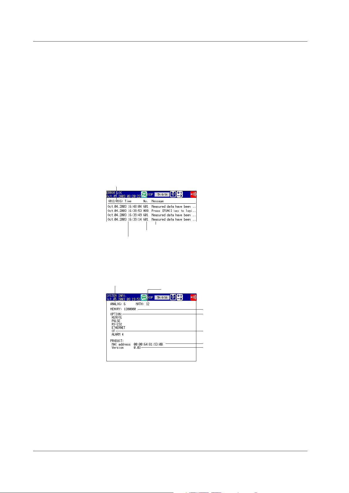
1.9 Other Functions
Key Login/Logout
Log Display
This function allows only certain users to access the FX100. The users are distinguished
by their name, user IDs, and passwords. Up to 7 users can be registered.
A list of phenomena that occurred can be displayed in the order of occurrence for the
following items:
• Error messages (50 most recent messages)
•A log of key login and logout (50 most recent logins)
•A log of communication commands (200 most recent commands)
•A log of file transfers using the FTP client function (50 most recent transfers)
•A log of e-mail transmissions (the 50 most recent transmissions)
•A log of Web operations (the 50 most recent operations)
Error Log Example
Displays the date and time of the error occurrence, error code number, and the
message.
The number of the log displayed at the last
line of the screen / total number of logs
System Screen
Error message
Error code
Date and time of occurrence
The total number of inputs on the FX100, capacity of the internal memory,
communication functions, external storage drive, options, MAC address, and the
firmware version number can be displayed.
Number of measurement channels
Number of computation channels
Internal memory capacity
Optional functions
External storage medium
MAC address
Firmware version number
1-56
IM 04L20A01-01E
Page 68

1.9 Other Functions
Displayed Language
The displayed language can be set to English, Japanese, German, or French.
Snapshot
The image data displayed on the screen can be saved to the external storage medium
through key operation. The data is in PNG format and can be pasted to commercially
sold software programs such as document creation software.
Note
Daylight Savings Time
• When the specified time is reached at which the daylight savings time adjustment is to
• When the specified time is reached at which the daylight savings time adjustment is to
1
Explanation of Functions
This function is available on the following models.
• Models with an external storage drive, or;
• Models with the Ethernet communication interface (/C7 option) that are set up for snapshot
FTP transfer.
be enabled, the FX100 automatically sets the clock ahead by one hour.
Example: If the time is set to 9 o’clock on June 1, the time is set ahead to 10 o’clock
June 1.
be disabled, the FX100 automatically sets the clock back by one hour.
Example: If the time is set to 9 o’clock on December 1, the time is set back to 8
o’clock December 1.
Temperature Unit
The temperature unit can be set to Celsius ( °C) or Fahrenheit ( °F). This applies to all
channels.
IM 04L20A01-01E 1-57
Page 69

Chapter 2 Installation and Wiring
2.1 Handling Precautions
This section describes the precautions to be taken when using the FX100 and the
external storage medium. Make sure to read this section before using the FX100.
Handling Precautions for the FX100
• This instrument uses many plastic parts. When cleaning, wipe using a dry soft cloth.
Do not use volatile chemicals since this might cause discoloring and deformation.
• Do not bring charged objects near the signal terminals. Doing so can lead to
malfunction.
• Do not pour volatile agents on the LCD, panel keys, or other parts of the instrument
nor leave them in contact with rubber or PVC products for an extended time. Doing
so can lead to malfunction.
• Do not apply shock to the instrument.
• When not in use, make sure to turn OFF the power.
• If there are any symptoms of trouble such as smoke, strange odors, or strange
sounds coming from the instrument, immediately turn OFF the power and disconnect
power supply. Then, contact your nearest YOKOGAWA dealer or representative.
Handling Precautions for the External Storage Medium
• Use caution in the handling of the external storage medium as it is delicate.
• Write operations to floppy disks may fail in high-temperature or low-temperature
environments. If you are using the FX100 in a low-temperature environment (around
10 °C or less), use the FX100 after the warm-up time (at least 30 minutes) has
elapsed.
If you are using the FX100 in a high-temperature environment (around 40 °C or
more), it is recommended that the external storage medium be inserted into the drive
when saving the data and be removed after the data storage operation is finished.
• For the general handling precautions of the external storage medium, see the
instruction manual that came with that medium.
2
Installation and Wiring
IM 04L20A01-01E
CAUTION
• Do not eject the external storage medium while the access lamp is illuminated.
This can damage the data.
• Do not operate the floppy disk drive in a place with vibrations or shock. The disk
or drive may malfunction.
2-1
Page 70

2.2 Installation
Installation Location
Install the instrument indoors, in a location that meets the following conditions. The
environment of the installation location is described in
Specifications.”
• Instrumentation panel
The FX100 is designed to be installed in an instrumentation panel (panel mount type).
• Well-ventilated location
Install the instrument in a well-ventilated location to prevent the temperature inside the
instrument from rising. For the panel cut dimensions when arranging multiple FX100,
see the next page. Also, when other instruments are arranged on the panel, allow
adequate space between them.
• Location where mechanical vibration is small
Select a location with low mechanical vibration for installation.
• Horizontal location
When installing the FX100, make sure it does not tilt to the left or right (0 to 30
degrees of backward tilt angle is allowed).
Note
• Condensation may occur if the instrument is moved to another place where the ambient
temperature is higher, or if the temperature changes rapidly. In addition, measurement
errors will occur when using thermocouple input. In this case, let the instrument adjust to
the new environment for at least an hour before using it.
• The life of the LCD may shorten (degradation of the image quality) if the FX100 is used in
a high-temperature environment. It is recommended that the backlight brightness of the
LCD be set low if the FX100 is installed in a hot environment (around 40∞C or higher).
For a description on the LCD brightness setting, see section 3.4, “
the LCD and the Backlight Saver Function
section 12.6, “General
Setting the Brightness of
.”
Do not install the FX100 in the following places.
• Outdoors
• In direct sunlight or near heat appliances
Select a location with the smallest temperature fluctuation as possible near room
temperature (23 °C). Placing the FX100 in direct sunlight or near heat appliances can
cause adverse effects.
• Where an excessive amount of soot, steam, dust, or corrosive gases are
present
Soot, steam, humidity, dust, and corrosive gas can cause adverse effects on the
FX100. Avoid installing the FX100 in an environment with a high level of such
elements.
• Near magnetic field sources
Avoid bringing magnets or instruments that produce magnetic fields near the FX100.
Using the FX100 near a strong magnetic field source can cause measurement errors.
• Where the view of the display is poor
The FX100 uses a LCD for the display. Therefore, viewing of the display from an
extreme angle is difficult. Install the FX100 so that the user can easily view the
display.
2-2 IM 04L20A01-01E
Page 71

Installation Procedure
Use a 2 mm to 26 mm thick steel plate for the panel on which the FX100 is to be mounted.
2.2 Installation
1. Insert FX100 from the front of the panel.
2. Using the mounting brackets that came with the package, secure the FX100 to
the panel as shown in the following figure.
• Two mounting brackets are used at the top and bottom or left and right of the
case (remove the seal covering the holes of the mounting brackets on the
case beforehand).
• The adequate tightening torque of the screws for the panel mounting
brackets is 0.7 to 0.9 N·m.
• Mount the FX100 to the panel according to the procedure below.
• First, attach the two mounting brackets and temporarily fasten the
attachment screws.
• Next, fix the FX100 in place by tightening the attachment screws with the
appropriate torque. When the FX100 is approximately perpendicular to
the panel as you fasten the screws, press the mounting bracket against
the case so that they are in contact with each other.
CAUTION
Tightening the screws with a torque greater than the adequate tightening torque
can cause deformation of the case or damage to the bracket.
2
Installation and Wiring
Screw temporarily Fix in place
(The figure shows the case when the mounting brackets are used on the top and bottom of the case.)
Single-Unit Mounting
+2
137
0
(5.39)
+2
0
137
(5.39)
Panel Mounting Diagram
Panel
Mounting bracket
Panel Cut Diagram
Side-by-Side Mounting
(horizontally)
+2
0
(5.39)
137
+2
L
0
Attachment screw
Side-by-Side Mounting
(vertically ,max. 3units)
(6.89)
175Min
Front
Panel
Case
Mounting bracket
Attachment screw
Unit: mm (approx. inches)
+2
137
0
(5.39)
+2
0
L
In contact
with each other
Tor que driver
(flat blade)
+2
Units
L
0
2 282
3
4
5
6
7
8
9
10
(144xn)−6
n
(mm)
426
570
714
858
1002
1146
1290
1434
IM 04L20A01-01E
175Min
(6.89)
2-3
Page 72

2.2 Installation
External Dimensions of the FX100
FG SG
SDB SDA RDB RDA
10Base-T
RS-422A/485
NO.
FREQUENCY
SUPPLY
SUFFIX
STYLE
MODEL
TAG NO.
TAG NO.
TAG NO.
TAG NO.
TAG NO.
TAG NO.
151.5 (5.96)
144 (5.67)
23.4
(0.92)
Unit: mm (approx. inches)
9.4 (0.37)
(Dimensions before the mounting
bracket is attached)
175 (6.89)
Thickness of the attachment panel
2 to 26
58.4
(2.30)
144 (5.67)
151.5 (5.96)
7.5 (0.30)
(Dimensions after the mounting
bracket is attached)
The dimensional tolerance is ±3% unless otherwise specified (However, the tolerance for
dimensions less than 10 mm is ±0.3 mm).
Note
For FX100s which are side-by-side mounted vertically, when a front panel is opened the
down arrow key may interfere the upper front panel.
136.5 (5.37)
2-4 IM 04L20A01-01E
Page 73

2.3 Measurement Input Terminal Wiring
General Precautions When Wiring the Measurement Input Signal Wires
WARNING
• To prevent the possibility of electric shock when wiring, confirm that the power
supply source is turned OFF.
CAUTION
• If a large pulling force is applied to the input/output signal wires connected to the
FX100, the terminal or signal wire may become damaged. To prevent this from
happening, fix all the wiring cords to the rear of the installation panel.
• Do not apply a voltage exceeding the following value to the input terminals.
Otherwise, damage to the unit may result.
• Maximum input voltage
Voltage range less than or equal to 200 mVDC, TC, RTD, and DI: ±10 VDC
Other DC voltage ranges: ±60 VDC
• Maximum common mode voltage
±60 VDC (under the measurement category II)
• The FX100 is an installation category II product.
2
Installation and Wiring
Ensure that noise does not enter the measurement circuit.
• Keep the measurement circuit away from the power supply cable (power supply
circuit) and ground circuit.
• It is desirable that the object under measurement is not a noise source. However, if
this is not avoidable, insulate the object under measurement and the measurement
circuit. In addition, ground the object under measurement.
• Shielded wires are effective against noise caused by electrostatic induction. As
necessary, connect the shield to the ground terminal of the FX100 (make sure this
does not lead to grounding at two points).
• Twisting the measurement circuit wires at short intervals is relatively effective against
noise caused by electromagnetic induction.
• Make sure to ground the protective ground terminal through a small grounding
resistance (less than or equal to 100 Ω).
When using the reference junction compensation of the FX100 through thermocouple
input, take measures to stabilize the temperature at the terminal section.
• Always attach the terminal cover.
• Do not use thick wires with high heat radiations effects (cross-sectional area of 0.5
2
mm
or smaller recommended).
• Keep the ambient temperature consistent. Large temperature fluctuations can occur
as a result of such things as turning ON/OFF a nearby fan.
Connecting the input wires in parallel with other instruments may mutually affect
the measured values. If you need to make a parallel connection:
• Turn OFF burnout.
• Ground each instrument at a single common point.
• Do not turn ON/OFF the instrument during operation. It may cause adverse affects on
other instruments.
• Resistance temperature detectors cannot be connected in parallel.
IM 04L20A01-01E
2-5
Page 74

2.3 Measurement Input Terminal Wiring
Arrangement of the Measurement Input Terminal Blocks
The measurement input terminal blocks are arranged on the rear panel of the FX100 as
shown in the figure below.
Terminal cover screws
Measurement input terminal blocks
A terminal cover is screwed over the measurement input terminal blocks. A label
showing the arrangement of the terminals is affixed to the cover.
Note
• The installation position of each terminal block is fixed and cannot be changed.
• For a description on the connection of communication interfaces such as the serial or
Ethernet interface, see the “
17E).
FX100 Communication Interface User’s Manual ”
(IM04L20A01-
FX103
Wiring Procedure
Removing the terminal block
Hold both sides of the terminal
block, then pull straight out.
Measurement Input Assignments on the Measurement Input Terminal Block
Measurement inputs are assigned on the FX103, FX106, and FX112 as shown in the
figure below. One measurement input uses three terminals.
FX112
231564
8971112 10
231
FX106
231564
1 to 12: Measurement input channel numbers
1. Turn OFF the power to the FX100, then remove the terminal cover.
2. Wire the signal wire to the terminal.
Remove the measurement input terminal block to perform the wiring.
Wire gauge: 0.2–2.5 mm
Connecting Wires
Insert the input signal wire into the
slit on the underside of the terminal
block, then use a flathead screwdriver
to tighten the front screw.
2
(AWG24–AWG17)
Flathead driver
Recommended length
of wire stripping: 7 mm
Input signal wire
2-6 IM 04L20A01-01E
Page 75

Reattaching the Terminal Block
Align the terminal block with the connectors on the main unit,
then push in. Push completely in until it stops.
3. Attach the terminal cover, then fasten with screws.
Measurement Input Wiring
2.3 Measurement Input Terminal Wiring
2
Installation and Wiring
Thermocouple input
b
A
B
Extension
leadwire
DC voltage or DI input
b
A
B
–
+
DC voltage or DI input
Note
On the standard measurement input block, RTD input terminals A and B are isolated on each
channel. Terminal b is shorted internally across all channels. If you specified the three-wire
isolated RTD (/N2) option, b terminals are isolated with each other.
Resistance temperature detector input
Leadwire resistance: 10 Ω max./wire
The resistance of the three wires
should be approximately equal.
Shunt resistor
NOTE: For a 4 to 20 mA
input, use a shunt
resistor of 250 Ω ±0.1%.
b
A
B
B
b
A
DC current input
b
A
B
–
+
DC current input
IM 04L20A01-01E
2-7
Page 76

2.4 Optional Input/Output Terminal Wiring
General Precautions When Wiring the Input/Output Signal Wires
WARNING
• To prevent the possibility of electric shock when wiring, confirm that the power
supply source is turned OFF.
• If a voltage greater than or equal to 30 VAC/60 VDC is going to be applied to the
output terminals, use round crimp-on lugs with insulation covers (to prevent the
wires from coming loose) for connecting the signal wires on all output terminals. In
addition, use double insulated wires (withstand voltage of 2300 VAC or more) for
signal wires to which a voltage greater than or equal to 30 VAC/60 VDC is to be
applied and basic insulation wires (withstand voltage of 1350 VAC or more) for all
other signal wires. To prevent the possibility of electric shock, attach the terminal
cover after connecting the wires and keep your hands away from the terminals.
CAUTION
If a large pulling force is applied to the input/output signal wires connected to the
FX100, the terminal or signal wire may become damaged. To prevent this from
happening, fix all the wiring cords to the rear of the installation panel.
Arrangement of the Option Terminal Block
The option terminal block is arranged on the rear panel of the FX100 as shown in the
figure below.
The option terminal block is included when the following option codes are specified.
Alarm output relay (option code: /A1, /A2, /A3), FAIL/memory end output relay (option
code: /F1), remote control (option code: /R1), pulse measurement input (option code: /
PM1)
A terminal cover is screwed on the option terminal block. A label showing the
arrangement of the terminals is affixed to the cover.
Note
• The installation position of each terminal block is fixed and cannot be changed.
• For a description on the connection of communication interfaces such as the serial or
Ethernet interface, see the “
17E).
Terminal cover screws
Option terminal block
FX100 Communication Interface User’s Manual
” (IM04L20A01-
2-8 IM 04L20A01-01E
Page 77
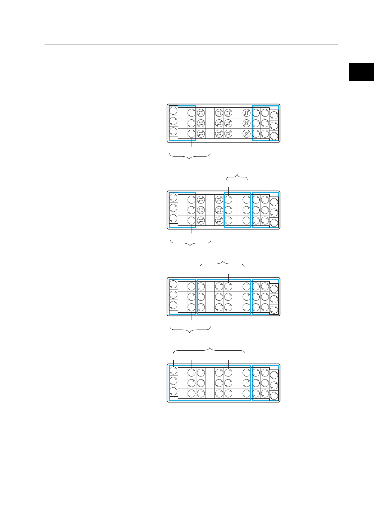
2.4 Optional Input/Output Terminal Wiring
Terminal Arrangement on the Option Terminal Block
Terminals are arranged as shown in the figure below according to the options
installed. You can use only the terminals that correspond to the options you
purchased.
• When pulse input (/PM1) is not installed
Remote input (/R1)
Without alarm
output terminals
NC
NC
C
C
NO
NO
FAIL
Memory end
FAIL/Memory end output (/F1)
Alarm output (/A1)
6 3
7 4
C
1
58
2
2
Installation and Wiring
With /A1
With /A2
With /A3
02 01
NC
C
NO
FAIL
NC
C
NO
Memory end
NC
C
NO
FAIL/Memory end output (/F1)
Alarm output (/A2)
02 0104 03
NC
NC
NC
NC
NC
C
C
C
C
C
NO
NO
NO
NO
NO
FAIL
Memory end
FAIL/Memory end output (/F1)
Alarm output (/A3)
02 0104 0306 05
NC
NC
NC
NC
NC
C
C
C
C
C
NO
NO
NO
NO
NO
Remote input (/R1)
6 3
NC
C
NO
7 4
C
1
58
2
Remote input (/R1)
6 3
NC
C
NO
7 4
C
1
58
2
Remote input (/R1)
6 3
NC
C
NO
7 4
C
1
58
2
IM 04L20A01-01E
NC (normally closed), C (common), NO (normally opened): Relay contact output terminal
1 to 8, C (common): Remote input terminal
The alarm output terminals 01 to 06 are indicated using [I01] to [I06] in the alarm output
settings.
The remote input terminals 1 to 8 are indicated using numbers 1 to 8 in the remote
output settings.
2-9
Page 78

2.4 Optional Input/Output Terminal Wiring
• When pulse input (/PM1) is installed
Without alarm
output terminals
Pulse input (/PM1)
NC
NC
C
C
NO
NO
FAIL
Memory end
FAIL/Memory end output (/F1)
Alarm output (/A1)
Remote input (/PM1)8 7 6
HH 3
H
L L
L 4
C
1
5
2
Pulse input (/PM1)
With /A1
NC
C
NO
FAIL
02 01
NC
NC
C
C
NO
NO
Memory end
NC
NO
H
C
L L
HH 3
L 4
Remote input (/PM1)8 7 6
C
1
5
2
FAIL/Memory end output (/F1)
With /A2
Alarm output (/A2)
02 01
NC
NC
NC
C
C
C
NO
NO
NO
Pulse input (/PM1)
NC
NO
H
C
L L
HH 3
L 4
Remote input (/PM1)04 03 8 7 6
C
1
5
2
NC (normally closed), C (common), NO (normally opened): Relay contact output terminal
1 to 8, C (common): Remote input terminal
H, L: Pulse input terminals
The alarm output terminals 01 to 06 are indicated using [I01] to [I06] in the alarm output
settings.
The remote input terminals 1 to 8 are indicated using numbers 1 to 8 in the remote
output settings.
The pulse input terminals 6 to 8 are indicated using numbers 6 to 8 in the pulse input
settings.
2-10 IM 04L20A01-01E
Page 79

Alarm Output, FAIL/Memory End Output Wiring
Use crimp-on lugs with isolation sleeves (for 4-mm screws) when connecting the input/
output signal wires to the terminals.
Crimp-on lug with isolation sleeve
(for 4-mm screw)
Relay contact output
NC
C
NO
Relay Output Specifications
Output format: Relay contact
Contact rating: 250 VAC (50/60 Hz)/3 A or 250 VDC/0.1 A (resistive load)
Dielectric strength: 1600 VAC (50/60 Hz) for 1 minute (between the input terminal and
earth)
Remote Input, Pulse Input Wiring
Use crimp-on lugs with isolation sleeves (for 4-mm screws) when connecting the input/
output signal wires to the terminals.
2.4 Optional Input/Output Terminal Wiring
2
Installation and Wiring
Crimp-on lug with isolation sleeve
(for 4-mm screw)
Remote input
• Relay contact input (non-voltage contact)
6
7
8
Pulse input
• Relay contact input (non-voltage contact)
87 6
H
L
3
4
5
H
L
• Transistor input (open collector)
C
1
2
• Transistor input (open collector)
H
L
6
7
8
H
L
3
4
5
H
L
Relay Contact Input and Transistor Input Specifications
Input signal:
• Non-voltage contact:
Close: 200 Ω or less, Open: 100 kΩ or more
• Open collector
0.5 V or less (30 mADC) when turned ON, leakage current of 0.25 mA or less when
turned OFF
Input format: Photocoupler isolation (shared common)
Dielectric strength: 1000 VDC for 1 minute (between the input terminal and earth)
C
1
2
678
H
L
IM 04L20A01-01E
2-11
Page 80

2.5 Wiring the Power Supply
Precautions to Be Taken When Wiring the Power Supply
Make sure to follow the warnings below when wiring the power supply. Otherwise,
electric shock or damage to the FX100 may result.
WARNING
• To prevent the possibility of electric shock when wiring, confirm that the power
supply source is turned OFF.
• To prevent the possibility of fire, use a power line or cord that is equivalent to
600 V PVC insulated wire (AWG 18) or better.
• Make sure to ground the protective ground terminal through a grounding
resistance of less than or equal to 100 Ω before turning ON the power.
• Use crimp-on lugs with isolation sleeves (for 4-mm screws) for power supply
wires and protective grounding wires.
• To prevent the possibility of electric shock, make sure to close the cover
(transparent) for the power supply wires.
• Furnish a switch (double-pole type) to separate the FX100 from the main power
supply in the power supply line. In addition, make sure to indicate that the
switch is a power control for the FX100 on the switch and the ON/OFF positions
of the switch.
Switch Specifications
Steady-state current rating: 1 A or more, inrush current rating: 60 A or more
Use a switch complied with IEC60947-1 and 3.
• Connect a fuse between 2 A and 15 A in the power supply line. Use a fuse
approved by CSA (for the use in North America) or VDE (for the use in Europe).
• Do not add a switch or fuse to the ground line.
Use a power supply that meets the following conditions:
Except for /P1 model
Item Specification
Rated supply voltage: 100 to 240 VAC
Supply voltage range used: 90 to 132, 180 to 264 VAC
Rated supply voltage frequency: 50/60 Hz
Permitted supply voltage frequency range: 50/60 Hz ± 2%
Maximum power consumption: 25 VA (100 V), 35 VA (240 V)
/P1 model
Item Specification
Rated supply voltage: 24 VDC/AC
Supply voltage range used: 21.6 to 26.4 VDC/AC
Rated supply voltage frequency: 50/60 Hz (for AC)
Permitted supply voltage frequency range: 50/60 Hz ± 2% (for AC)
Maximum power consumption: 17 VA (for DC), 30 VA (for AC)
Note
• Do not use a supply voltage in the range 132 to 180 VAC, as this may have adverse effects
on the measurement accuracy (applies to all models except for the ones with /P1 option).
• The FX100 has no power switch. Use an external switch to turn the power ON and OFF.
2-12 IM 04L20A01-01E
Page 81

Power Terminal and Protective Ground Terminal Arrangement
Power terminals and protective ground terminal are arranged as shown in the figure
below.
Power terminals / Protective ground terminal
Terminal cover screw
Wiring Procedure
1. Turn OFF the power to the FX100, and open the cover (transparent) for the
power supply wires.
2. Connect the power cord and the protective ground cord to the power supply
terminals. Use crimp-on lugs with isolation sleeves (for 4-mm screws).
except for /P1 model for /P1 model
100-240V AC
50/60Hz 35VAMAX
L N
24V DC 17VA MAX
24V AC~50/60Hz 30VA MAX
L(+) N(-)
2.5 Wiring the Power Supply
2
Installation and Wiring
Tightening torque for
cover screws: 0.6N•m
Crimp-on lug with
isolation sleeve
Power supply wires
Protective ground wire
3. Close the cover (transparent) for the power supply wires and secure it in place
with screws.
IM 04L20A01-01E
2-13
Page 82

Chapter 3 Names of Parts, Display Modes, and Common Operations
3.1 Names of Parts and Functions
Front Panel
Operation Key
1
Operation key panel tab
2
45
1. LCD screen
Displays various operation screens such as the trend display and the setup screen to
configure the FX100.
2. Operation key panel
Operation keys are arranged. Open the panel by pushing down on the tab located at
the center of the top edge of the cover and pulling it forward when inserting or
removing the external storage medium such as floppy disks and CF memory cards.
3. DISP/ENTER key and four Arrow keys
The keys are used to switch the operation screen in the operation mode. In the setup
screens, the keys are used to select parameters and to confirm the new settings.
4. START key
Used to start the data acquisition to the internal memory and display the waveform on
the trend screen.
5. STOP key
Used to stop the data acquisition to the internal memory. It also stops the updating of
the waveform on the trend screen.
6. USER key
Executes the action assigned to this key.
7. FUNC key
If the key is pressed in operation mode, a soft key menu is displayed at the bottom
section of the display enabling the execution of various functions. The key is also
used when switching from setting mode to operation mode.
8. ESC key
Used to cancel an operation. Also used to return to the operation mode from the
setting mode or return to the menu screen from setting screens..
9. MENU key
Used to enter the setting mode. Also used to return to the operation mode from the
setting mode.
10. Soft keys
When a soft key menu is displayed at the bottom section of the display in operation
mode, setting mode, or basic setting mode, these soft keys are used to carry out
operations or to change the setup information.
6107
89
3
Names of Parts, Display Modes, and Common Operations
3
IM 04L20A01-01E
The information above explains the basic functions of each key. For a description
on how to operate the keys, see section 3.2, “Basic Key Operations.”
3-1
Page 83

3.1 Names of Parts and Functions
Floppy Disk Drive/Compact Flash Card Slot
The floppy disk drive or compact flash memory card slot is visible when you open the key
panel. However, no drive or slot is present on models with no external storage medium
specified.
Rear Panel
Do not remove
the cover.
Repair by trained
personal only.
MODEL
SUFFIX
NO.
STYLE
Do not remove
the cover.
Repair by trained
personal only.
MODEL
SUFFIX
NO.
STYLE
1 23 21
1. Floppy Disk Drive/Compact Flash Memory Card Slot
Depending on the specification you made at the time of purchase, either a floppy disk
drive or an CF memory card slot is installed.
2. Eject button
Used when ejecting the external storage medium.
3. Floppy disk access lamp
Illuminates when data is being written or read.
The terminal blocks and connectors that are installed in the rear panel varies depending
on the specification you made at the time of purchase.
RS-422A/485 serial interface port (only when specified)
10BASE-T Ethernet port (only when specified)
Power terminals / Protective ground terminal
RS-232 serial interface port (only when specified)
Option terminal block
Measurement input terminal blocks
Circuits for reference junction compensation are
built in. Do not remove the cover.
For a description on how to connect the input/output signal wires and power supply cables,
see chapter 2, “
For a description on how to use the communication ports, see the
Interface User’s Manual
Installation and Wiring
” (IM 04L20A01-17E).
.”
“FX100 Communication
3-2 IM 04L20A01-01E
Page 84

3.2 Basic Key Operations
Switching Operation Modes
The FX100 has thee operation modes: operation mode, setting mode, and basic setting
mode. Many of the settings in basic setting mode are prerequisites for the settings.
Therefore, enter these settings first.
Mode Types Description Main Operations Possible
Operation mode Mode used to conduct measurement. • Display measured data.
Contains a screen for displaying the • Save or abort the saving of the
measured data, operation history, etc. measured data.
Setting mode Mode used to set parameters* that are • Set the operation of the
changeable during measurement. measurement functions.
Basic setting mode Mode used to set basic items such as • Set basic items of each function.
the input format and the data storage • Set communication parameters.
format. You cannot switch to basic • Initialize the internal memory.
setting mode while data acquisition or
computation is in progress.
* Some of the items such as the input range or computation settings cannot be changed during
data acquisition to the internal memory, or during computation.
Display Transition Diagram
Setting ModeOperation Mode
[End] soft key > DISP/ENTER key
3
Names of Parts, Display Modes, and Common Operations
• Set items related to the display
format.
Basic Setting Mode
Operation screens
Power ON
Procedure
Hold down
MENU key
Menu screens Menu screens
MENU key
or
ESC key
Soft key Soft key ESC key
Setting screens Setting screens
the FUNC
key for 3 s.
MENU key
or
ESC key
Operation Keys
Switching the Operation Mode and Setting Menu
The display switches each time the MENU key is pressed. The ESC key can also be
used when switching to the operation mode from the setting menu.
IM 04L20A01-01E
3-3
Page 85

3.2 Basic Key Operations
Switching Operation Mode to Basic Setting Menu
1. Press the MENU key to display the setting menu.
2. Press the FUNC key for at least 3 seconds.
Note
• You cannot switch to basic setting mode while data is being acquired to the internal memory,
while computation is in progress, or while the external storage medium is being accessed.
Stop the data acquisition to the internal memory and computation before switching to basic
setting mode.
• If you change the settings under [#3 Memory] or [#4 Memory and trend, Memory timeup]
(excluding memory time up items) in basic setting mode, save the new settings and return to
operation mode, the measured data in the internal memory is cleared. Save important data to
the external storage medium before entering basic setting mode.
Switching Screens on the Operation Mode
You can change the operation screens according to your needs by carrying out the
following procedures.
Procedure
Operation Keys
1. Press the DISP/ENTER key to show the screen menu.
2. Select the menu item using the up and down arrow keys.
3. Press the right arrow key to display the sub menu.
To close the sub menu that you opened, press the left arrow key.
4. Select the sub menu item using the up and down arrow keys.
5. Press the DISP/ENTER key.
The selected display appears.
To close the menu without switching the display, press the ESC key.
1
Screen menu
45
23
Sub menu
3-4 IM 04L20A01-01E
Page 86

3.2 Basic Key Operations
FUNC Key Operation in Operation Mode
The following operation can be carried out in operation mode.
Menu Reference Function (conditions displayed on the soft key menu)
Media 7.3 Detects the external storage medium in the drive (only on models with a
Alarm ACK 4.2 Clears alarm display/relay output (valid only when the operation of the alarm
Message 6.4 Displays messages 1 to 8 on the trend screen and writes them to the internal
Manual sample 7.4 Acquires measured data of all channels to the internal memory.
Key lock 9.2 Enables/disables key lock (only when key lock is used)
Log out 9.3 Logs out (only when logged in using the key login function)
Trigger 7.2 Trigger used to start acquiring event data to the internal memory (valid only
Math START/ Math STOP 8.2 Starts/stops computation (only for models with the computation function (/M1, /
Math reset 8.2 Resets the computed value of the computation channel to 0 (only on models
Math ACK 8.2 Recovers the computation dropout indication icon to normal indication (only on
Snapshot
Log 9.4, 3.8 Displays the log screens/system information screen.
Save Display
Save Event
FTP test
E-Mail START/E-Mail STOP
E-Mail test
Modbus master
*1 Available on models with the Ethernet interface, regardless of whether an external storage medium drive is installed.
*2 See the ”
*1
*1
*1
7.5 Saves the screen image data to the external storage medium.
7.3 Stores the display data to the external storage medium (only when the display
7.3 Stores the event data to the external storage medium (only when the event data
*2
*2
*2
*2
FX100 Communication Interface User’s Manual
external storage drive).
display or output relay is set to “hold”).
memory.
when event data is specified to be acquired to the internal memory and the
trigger used to start the acquisition is set to key trigger).
PM1 option))
with the computation function (/M1, /PM1 option), while the computation is
stopped).
models with the computation function (/M1, /PM1 option), when computation
dropout occurs)
data is being acquired to the internal memory).
is being acquired to the internal memory in the free mode). internal memory in
the free mode).
Executes an FTP test.
Enables/disables the e-mail transmission function.
Sends test messages to recipient 1 and 2.
Displays the Modbus status when the Modbus master function is used.
” (IM04L20A01-17E).
3
Names of Parts, Display Modes, and Common Operations
Procedure
IM 04L20A01-01E
Operation Keys
1. Press the FUNC key.
As shown in the following figure, menu assigned to the soft keys is displayed.
The menu varies depending on the setup information and options.
2. Press the soft key corresponding to the function you wish to execute.
If [Next 1/n] (where n is the number of menu lines) appears at the right end of
the menu, this indicates that there are multiple lines of menus. Press the [Next
1/n] soft key to view the next menu.
Press a soft key to execute the function assigned to it. The result of the soft key
being pressed varies depending on its function, as is explained in later sections
of this manual. To clear the menu without executing functions, press the FUNC
or ESC key.
3-5
Page 87

3.2 Basic Key Operations
Operation of Other Keys in Operation Mode
Procedure
Operation Keys
START/STOP Key
• Starts/stops the data acquisition to the internal memory. The waveform display on the
trend screen is also started/stopped.
For the operating procedure, see section 7.2.
• On models with the computation function option (/M1, /PM1), this key is also used to
start/stop the computation and report.
USER Key
Executes the function assigned to it.
For the procedure in assigning a function to the USER key, see section 9.1.
Key Operations in Basic Setting and Setting Modes
See appendix 6, “
Procedure
Operation Keys
Settings
” for more about setting mode and basic setting mode.
Selecting Setup Items on the Menu
When the FX100 enters setting mode, a setting menu appears as shown in the figure
below. In this menu, select the items you wish to set by pressing the soft keys. To
close this menu, press the ESC key.
Selecting Setup Items on the Setting Display
1. Use the arrow keys to move the cursor (blue) to the appropriate item box.
The soft keys corresponding to the item are displayed at the bottom section of
the display.
3-6 IM 04L20A01-01E
Page 88
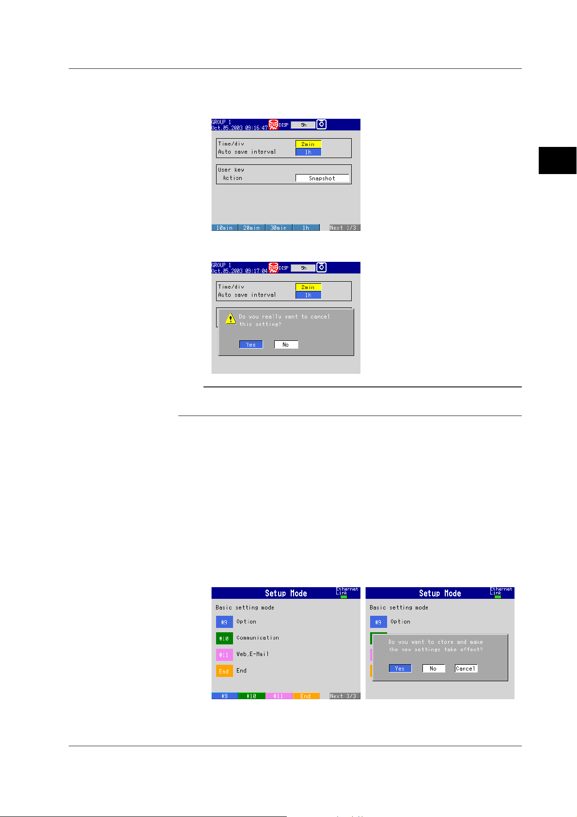
3.2 Basic Key Operations
2. Select the item using the soft key.
The box for the item you entered turns yellow, and the cursor moves to the next
item.
To cancel the settings, press the ESC key. On the cancel confirmation window
that appears, press the DISP/ENTER key with [Yes] is selected.
3
Names of Parts, Display Modes, and Common Operations
Note
If values or characters need to be entered, the soft key menu displays [Input]. For the
procedure in entering values and characters, see pages 3-8 and 3-9.
Confirming Settings on the Setting Displays
Press the DISP/ENTER key.
The item you entered is confirmed and the item box turns white again. The cursor
moves to the first item box on the setting display.
Switching from Setting Mode to Operation Mode
Display setting menu and press the ESC key.
Switching from Basic Setting Mode to Operation Mode and Saving the Basic
Settings
Display basic setting menu, and then carry out the following procedures.
1. Press the [End] soft key.
A confirmation window containing the message “Do you want to store and make
the new settings take effect?” appears.
IM 04L20A01-01E
3-7
Page 89

3.2 Basic Key Operations
Entering Values
Procedure
2. Press the DISP/ENTER key with [Yes] is selected.
The settings are saved and the FX100 returns to operation mode.
If you select [No] and press the DISP/ENTER key, the settings are not saved
and the FX100 returns to operation mode. In this case, the settings remain
unchanged. Selecting [Cancel] and pressing the DISP/ENTER key returns you
to basic setting mode menu. In this case, the on-going setting changes are
held.
A value must be entered when setting items such as the date/time and span lower/upper
limit. In such cases, a numeric entry pop-up window appears as shown in the following
figure. Follow the procedures below to enter the value.
Operation Keys
Entering Values
1. Use the left and right arrow keys to move the cursor (blue) to the position you
wish to enter a value.
2. Use the up and down arrow keys to select a value you wish to enter on the
number keypad.
The selected number is displayed at the cursor position.
3. Repeat steps 1 and 2 to change the value of all digits you wish to change.
4. Press the DISP/ENTER key.
The numeric entry pop-up window disappears and the value is set.
To cancel the settings and clear the numeric entry pop-up window, press the
ESC key.
Cursor (blue)
Select the input position using the left and right arrow keys.
Numeric entry pop-up window
Number keypad
Select the input number using
the up and down arrow keys.
3-8 IM 04L20A01-01E
Page 90
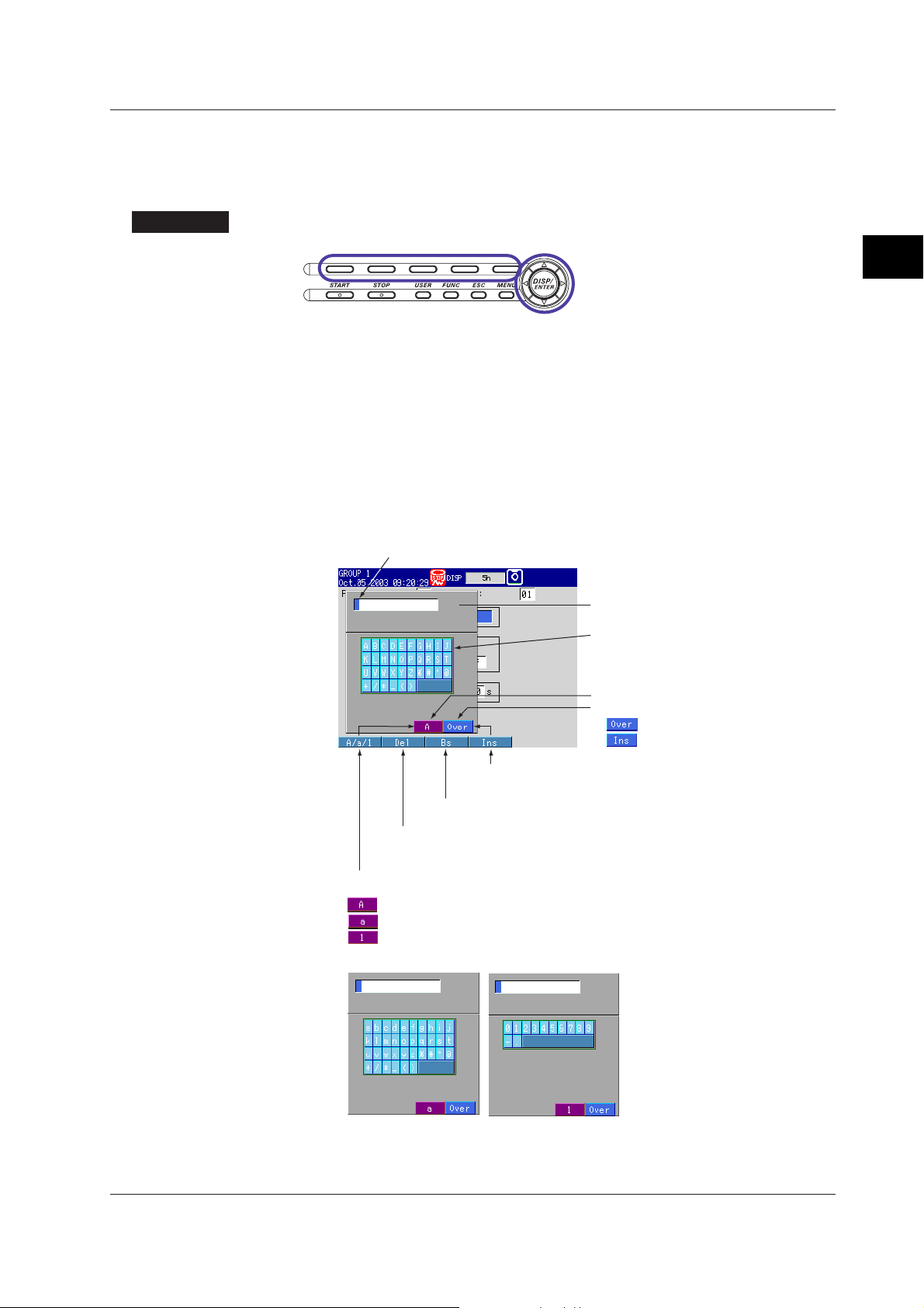
Entering Characters
Procedure
3.2 Basic Key Operations
Characters must be entered when setting items such as tag names and messages. In
such cases, a character entry pop-up window appears as shown in the following figure.
Follow the procedures below to enter the characters.
Operation Keys
3
Names of Parts, Display Modes, and Common Operations
1. Use the left and right arrow keys to move the cursor (blue) to the position you
wish to enter a character.
2. Use the up and down arrow keys to select a character you wish to enter on the
character keypad.
The selected character is displayed at the cursor position.
3. Repeat steps 1 and 2 to change all characters you wish to change.
4. Press the DISP/ENTER key.
The character entry pop-up window disappears and the character is set.
To cancel the settings and clear the character entry pop-up window, press the
ESC key.
Cursor (blue)
Select the input position using the left and right arrow keys.
[Ins] soft key
Switches between insert and overwrite.
[Bs] soft key
Deletes the character before the cursor position.
[Del] soft key
Deletes the character at the cursor position.
[A/a/1] soft key
Switches character types.
: Upper-case alphabet
: Lower-case alphabet
: Numbers
Lower-case alphabet
Numbers
Character entry pop-up window
Character keypad
Select the input character using
the up and down arrow keys.
Displayed character type
Overwrites or Inserts.
: Overwrites the cursor position.
: Inserts at the cursor position.
IM 04L20A01-01E
3-9
Page 91

3.3 Setting the Date and Time
This section explains how to set the date, time, and the daylight savings function of the
FX100 internal clock.
Date and Time <Setting Mode>
Procedure
Opening the Setting Display
• Setting the date and time
MENU key (switch to setting mode) > #8 soft key (select [Time])
From the operation mode, use the above keys to open the [Time] set pop-up window.
• Setting daylight savings time
MENU key (switch to setting mode) > #6 soft key (select [File, DST])
From the operation mode, use the above keys to open the [File, DST] set dialog box.
Setup Procedure
• Setting the Date and Time
1. Press the [Input] soft key while the cursor is on [YY/MM/DD HH:MM:SS].
The number keypad appears and the cursor (blue) moves to the [YY] section.
2. Enter the date/time using the left and right arrow keys to move the cursor
(blue), the up and down arrow keys to select a number.
3-10 IM 04L20A01-01E
Page 92

3.3 Setting the Date and Time
3. Press the DISP/ENTER key.
The keypad disappears and the cursor (blue) returns to the [YY/MM/DD
HH:MM:SS] box.
To set the Summer/Winter time, go to step 5 below.
4. Press the DISP/ENTER key.
The pop-up window disappears and the date/time is set.
To cancel the settings and close the [Time] set pop-up window, press the ESC
key.
• Selecting the summer or winter time
5. Use the right arrow key to shift the cursor (blue) to the [DST].
The selections are displayed at the bottom of the display.
3
Names of Parts, Display Modes, and Common Operations
6. Use the soft key to select [Summer] or [Winter].
7. Press the DISP/ENTER key.
The pop-up window disappears and the date/time is set.
To cancel the settings and close the [Time] set pop-up window, press the ESC
key.
• Setting daylight savings time
1. Use the arrow keys to move the cursor (blue) to the [Summer] or [Winter] box.
A soft key menu is displayed at the bottom of the display.
2. Press the soft key corresponding to the value you wish to change.
If you select [On], the box for the date and time appears to the right. The cursor
(blue) moves to the right.
3. Press the [Input] soft key.
The numeric entry pop-up window appears.
4. Enter the date/time using the left and right arrow keys to move the cursor
(blue), the up and down arrow keys to select a number.
5. Press the DISP/ENTER key.
The pop-up window disappears and the date/time is set.
To cancel the settings and close the pop-up window, press the ESC key.
6. Press the DISP/ENTER key to confirm the changes.
The boxes for the items you changed turn from yellow to white, and the cursor
returns to the first item box.
Setup Items
IM 04L20A01-01E
Daylight Savings Time
• Summer/Winter
• Off/On
When set to [On], the daylight savings time is enabled.
Summer: The time is set ahead one hour at the date and hour specified for
[Summer].
Winter: The time is set back one hour at the date and hour specified for [Winter].
3-11
Page 93

3.3 Setting the Date and Time
Note
• YY/MM/DD HH
Enter the date and hour when the time is to be changed.
Year (YY): Specified using the lower two digits. [00] to [79] represent year 2000 to
2079. [80] to [99] represent 1980 to 1999.
Month (MM): [01] to [12]
Date (DD): [01] to [31]
Hour (HH): [00] to [23]
When it elapsed the time set, the daylight saving time is automatically turned [Off]. Set
[Summer] and [Winter] time every year.
3-12 IM 04L20A01-01E
Page 94
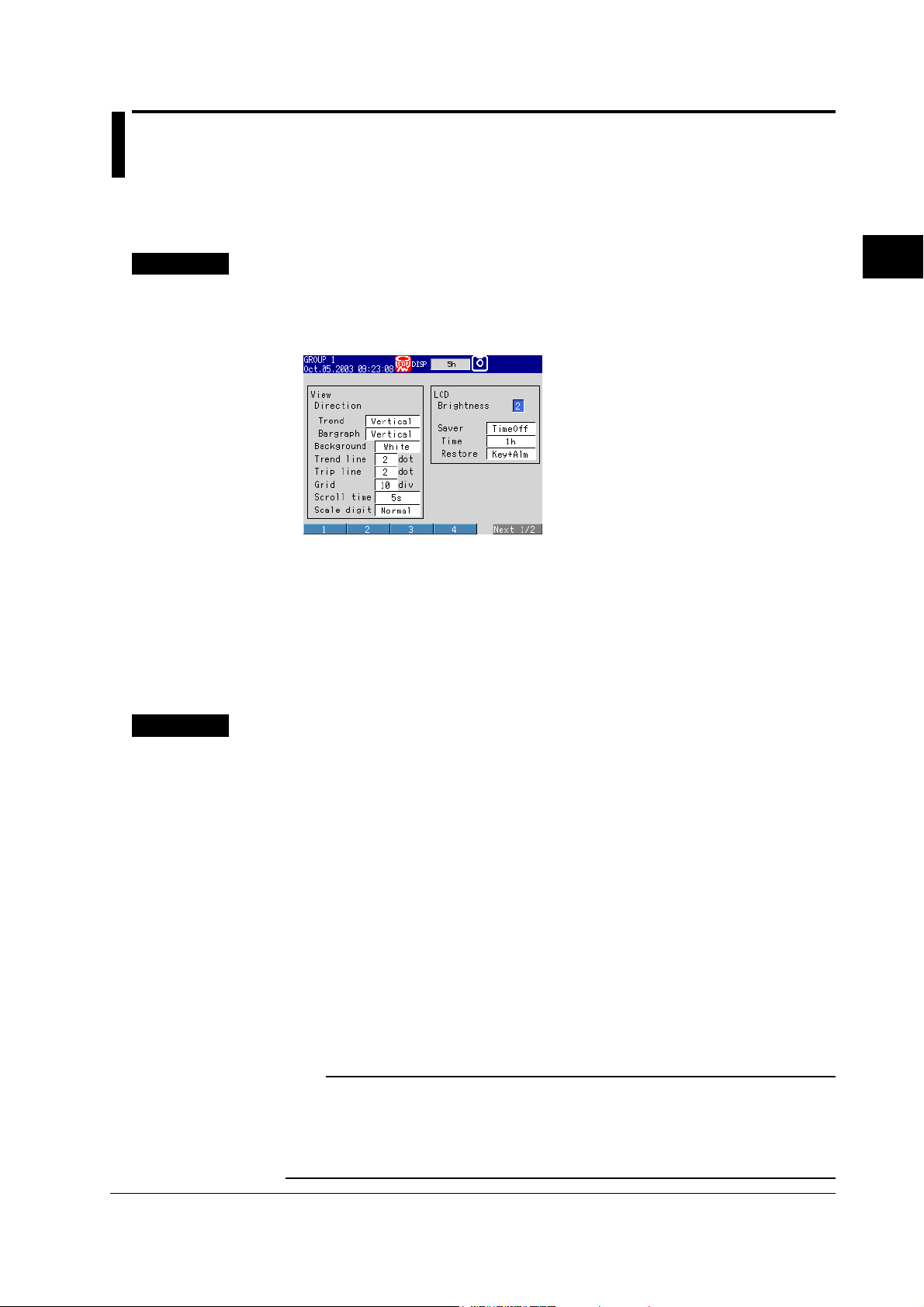
3.4 Setting the Brightness of the Display and the Backlight Saver Function
This section explains how to set the brightness of the LCD and the backlight saver
function used to prolong the life of the LCD backlight.
Brightness of the Display / Backlight Saver Function <Setting Mode>
Procedure
Opening the Setting Display
MENU key (switch to setting mode) > #5 soft key (select [Display]) > #4 soft key
(select [View, Direction, LCD]
From the operation mode, use the above keys to open the following setting display.
Setup Procedure
1. Use the arrow keys to move the cursor (blue) to the [Brightness] or [Saver].
The selections are displayed at the bottom of the display.
2. Press the soft key corresponding to the value you wish to change.
The box for the item you changed turns yellow, and the cursor moves to the next
item. If [Saver] is set to [On], [Time] and [Restore] entry boxes appear.
3. Repeat steps 1 and 2 to change the value of all the items you wish to change.
4.
Press the DISP/ENTER key to confirm the changes. The boxes for the items you
changed turn from yellow to white, and the cursor returns to the first item box.
Setup Items
Brightness of the Display / Backlight Saver Function
• LCD
• Brightness
Select a value from [1] to [8] (initial setting is 2). The larger the value, the brighter
the display becomes.
• Saver
Select [Dimmer], [TimeOff], or [NotOn] (do not use) for the LCD backlight saver.
Dimmer: LCD backlight is automatically dimmed.
TimeOff: LCD backlight is automatically turned off.
• Time
Select a value from [1min], [2min], [5min], [10min], [30min], [1h] (initial setting is
1h). If the specified time elapses without any key operation, the LCD backlight is
automatically dimmed or turned off.
• Restore
Key: The backlight returns to the original brightness on a key operation.
Key + Alm: The backlight returns to the original brightness on a key operation or an
alarm occurrence.
3
Names of Parts, Display Modes, and Common Operations
IM 04L20A01-01E
Note
• When the backlight is dimmed or completely off, the backlight saver function causes it to
return to its original brightness whenever you press any key on the FX100. When doing so,
the key’s primary function is not carried out.
• The degradation of the brightness and the discoloration of the screen (become yellowish)
tend to progress faster as the brightness is set higher. Extended use at an unnecessary high
setting should be avoided. It is also recommended that the backlight saver be used.
3-13
Page 95

3.5 Initializing the Setup Data and Clearing the Internal Memory
This section explains how to initialize the setup data in the internal memory to factory
default settings (initial settings) and how to clear the data in the internal memory.
For a list of initial settings, see appendix 6.
Initializing the Setup Data / Clearing the Internal Memory <Basic Setting Mode>
Procedure
Opening the Setting Display
MENU key (switch to setting mode) > Hold down the FUNC key for 3 seconds
(switch to basic setting mode) > #8 soft key (select [Save/Load, Initialize]) > #5 (or
*
#1
) soft key (select [Initialize])
* For models with no external storage drive.
From the operation mode, use the above keys to open the following setting display.
Setup Items
Setup Procedure
1. Press the soft key corresponding to the action you wish to carry out.
2. Press the DISP/ENTER key.
A confirmation dialog box appears.
3. Select [Yes] and press the DISP/ENTER key.
The action is executed and the FX100 returns to the operation mode.
To cancel the action and return to the operation mode, select [No] using the
arrow keys and press the DISP/ENTER key.
Clearing the Internal Memory
• Select the type of action from the following:
Clear1: Initializes the setup data of basic setting mode and setting mode and clears
the data in the internal memory.
Clear2: Initializes the setup data of setting mode and clears the data in the internal
memory.
Clear3: Clears the data in the internal memory.
• Data That Are Cleared
Items that are cleared are, display data, event data, manual sampled data, TLOG
data (/M1, /PM1 option), report data (/M1, /PM1 option), and log information.
3-14 IM 04L20A01-01E
Page 96

3.6 Changing the Displayed Language
This section explains how to change the language used on the display.
Displayed Language <Basic Setting Mode>
Procedure
Opening the Setting Display
MENU key (switch to setting mode) > Hold down the FUNC key for 3 seconds
(switch to basic setting mode) > #5 soft key (select [Aux, Time zone])
From the operation mode, use the above keys to open the following setting display.
Setup Procedure
1. Use the arrow keys to move the cursor (blue) to the [Language] box.
A soft key menu is displayed at the bottom of the display.
2. Press the soft key corresponding to the language you wish to select.
The [Language] box turns yellow, and the cursor moves to the next item.
3. Press the DISP/ENTER key to confirm the changes.
The boxes for the items you changed turn from yellow to white, and the cursor
returns to the first item box.
3
Names of Parts, Display Modes, and Common Operations
Note
On Version 1.10 or later, you can also select Spanish and Italian.
Saving the Settings
1. Press the ESC key.
The display returns to basic setting menu.
2. Press the [End] soft key.
A confirmation window appears.
3. Select [Yes] and press the DISP/ENTER key.
The operation screen is displayed.
IM 04L20A01-01E
3-15
Page 97

3.7 Changing the Time Zone
This section explains how to set the time difference with respect to Greenwich Mean
Time. Make sure to set this value if you are using the Web server function.
Time Zone <Basic Setting Mode>
Procedure
Opening the Setting Display
MENU key (switch to setting mode) > Hold down the FUNC key for 3 seconds
(switch to basic setting mode) > #5 soft key (select [Aux, Time zone])
From the operation mode, use the above keys to open the following setting display.
Setup Procedure
1. Use the arrow keys to move the cursor (blue) to the [Difference from GMT] box
under [Time zone].
[Input] is displayed at the bottom of the display.
2. Press the [Input] soft key.
The pop-up window appears.
3. Enter the time difference using the left and right arrow keys to move the
cursor (blue), the up and down arrow keys to select a number.
4. Press the DISP/ENTER key.
The pop-up window disappears and the time difference is set.
To cancel the settings and clear the pop-up window, press the ESC key.
5. Press the DISP/ENTER key to confirm the changes.
Saving the Settings
1. Press the ESC key.
The display returns to basic setting menu.
2. Press the [End] soft key.
A confirmation window appears.
3. Select [Yes] and press the DISP/ENTER key.
The operation screen is displayed.
Setup Items
Time Zone
Set the time difference with respect to Greenwich Mean Time from −1200 to 1200 (the
upper two digits indicate the hour; the lower two digits indicate the minute). The initial
value is set to “0.”
Example: The standard time in Japan is ahead of the Greenwich Mean Time by 9
hours. In this case, enter “900.”
3-16 IM 04L20A01-01E
Page 98

3.8 Confirming the System Configuration, Firmware Version Number, and MAC Address of the FX100
System Configuration, Firmware Version Number, MAC Address <Operation Mode>
Procedure
Opening the System Information Screen
1. In the operation mode, press the FUNC key.
A soft key menu is displayed at the bottom of the display.
2. Press the [Log] soft key.
A soft key menu is displayed at the bottom of the display.
3
Names of Parts, Display Modes, and Common Operations
Explanation
IM 04L20A01-01E
3. Press the [System] soft key.
The system information screen appears.
MAC address
Firmware version number
To return to the operation screen from the system screen, press the DISP/
ENTER key (display the screen menu) > upper/lower arrow key (select the
desired screen) > DISP/ENTER key.
System Information Screen
You can confirm the system configuration, firmware version number, and MAC
address of the FX100.
3-17
Page 99

3.9 Inserting and Ejecting the External Storage Medium
This section explains how to insert and eject the external storage medium. You can use
either type of external storage medium: floppy disk or CF memory card. The type of
external storage medium is specified at the time of purchase.
CAUTION
• Do not eject the external storage medium while the access lamp is illuminated.
This can damage the data.
• Do not operate the floppy disk drive in a place with vibrations or shock. The disk
or drive may malfunction.
For other information regarding the handling of the external storage medium, see section
2.1, “
Handling Precautions
Procedure
Inserting the Storage Medium
1. Pull open the key panel toward you while pushing down on the tab in the upper
middle part of the panel.
Insert a external storage medium to the drive and push in until you hear a click.
.”
Floppy DiskOpen the operation key panel CF Memory Card
For Compact Flash Memory Card
The CF memory card is detected and an icon that the CF memory card has
been inserted appears in the status display section of the screen.
External storage medium icon
For Floppy Disk
Go to step 2.
2. Press the FUNC key.
A soft key menu is displayed at the bottom of the display.
3-18 IM 04L20A01-01E
Page 100

3.9 Inserting and Ejecting the External Storage Medium
3. Press the [Media] soft key.
The floppy disk is detected, and the icon indicating that the floppy disk has been
inserted appears in the status display section of the screen.
Note
Keep the operation key panel closed at all times during operation except when inserting or
ejecting the external storage medium. The operation key panel protects the external storage
medium and the drive from foreign particles such as dust.
Ejecting the External Storage Medium
1. If the FX100 is turned ON, check that the external storage medium is not being
accessed.
Note
• The access lamp illuminates while the external storage medium is being accessed.
• If the data in the internal memory is being saved to the external storage medium, the
message “Data are being saved to the medium” appears.
2. Open the operation key panel by pressing down on the knob that is located in
the center of the upper section of the cover and pulling it forward.
3. Press the eject button and remove the external storage medium.
For floppy disk, press the FUNC key, then the [Media] soft key.
The external storage medium icon in the status display section disappears.
Floppy Disk
CF Memory Card
3
Names of Parts, Display Modes, and Common Operations
Setup Items
IM 04L20A01-01E
Eject button Eject button
4. Close the operation key panel.
Formatting the External Storage Medium
Use a formatted external storage medium.
The FX100 formats external storage media as follows (for the procedure in formatting
the external storage medium, see page 7-17).
• Floppy disk: 2HD, 1.44 MB.
• CF memory card: FDISK 1 partition (hard disk format).
External storage media that are formatted using other instruments can be used on the
FX100, if the format is the same. External storage media of formats other than those
listed above cannot be used.
3-19
 Loading...