

Page 1

User’s
Manual
FVX110
Fieldbus Segment Indicator
IM 01S01C01-01EN
IM 01S01C01-01EN
2nd Edition
Page 2

FVX110
Fieldbus Segment Indicator
IM 01S01C01-01EN 2nd Edition
Contents
1. Introduction ............................................................................................... 1-1
Regarding This Manual ................................................................................................1-1
1.1 Safe Use of This Product .................................................................................1-1
1.2 Warranty .............................................................................................................1-2
1.3 ATEX Documentation .......................................................................................1-3
2. Handling Cautions .................................................................................... 2-1
2.1 Model and Specications Check .....................................................................2-1
2.2 Unpacking ..........................................................................................................2-1
2.3 Storage ...............................................................................................................2-1
2.4 Selecting the Installation Location ................................................................2-1
2.5 Waterproong of Cable Conduit Connections ..............................................2-2
2.6 Restrictions on Use of Radio Transceivers ...................................................2-2
2.7 Insulation Resistance and Dielectric Strength Test ......................................2-2
2.8 Installation of an Explosion-Protected Instrument .......................................2-3
2.8.1 FM approval .......................................................................................2-3
2.8.2 CSA Certication ................................................................................2-7
2.8.3 CENELEC ATEX Certication ..........................................................2-10
2.8.4 IECEx Certication ...........................................................................2-13
i
3. Component Names .................................................................................. 3-1
4. About Fieldbus ......................................................................................... 4-1
4.1 Outline ................................................................................................................4-1
4.2 Internal Structure of FVX110 ............................................................................4-1
4.2.1 System/network Management VFD ..................................................4-1
4.2.2 Function Block VFD ...........................................................................4-1
4.3 Logical Structure of Each Block .....................................................................4-2
4.4 Wiring System Conguration ..........................................................................4-2
5. Installation ................................................................................................. 5-1
5.1 Precautions .......................................................................................................5-1
5.2 Mounting ...........................................................................................................5-1
5.3 Wiring .................................................................................................................5-2
5.3.1 Wiring Precautions .............................................................................5-2
5.3.2 Wiring Installation ...............................................................................5-2
5.4 Grounding ..........................................................................................................5-3
2nd Edition: July 2011(YK)
All Rights Reserved, Copyright © 2010, Yokogawa Electric Corporation
IM 01S01C01-01EN
Page 3

5.5 Connection of Devices .....................................................................................5-3
5.6 Host Setting .......................................................................................................5-4
5.7 Bus Power ON ...................................................................................................5-5
5.8 Integration of DD ...............................................................................................5-6
5.9 Set the Parameters Using DTM .......................................................................5-6
5.10 Continuous Record of Values ..........................................................................5-6
5.11 Generation of Alarm ..........................................................................................5-6
6. Conguration ............................................................................................ 6-1
6.1 Network Design .................................................................................................6-1
6.2 Network Denition ............................................................................................6-2
6.3 Denition of Combining Function Blocks ......................................................6-3
6.4 Setting of Tags and Addresses .......................................................................6-4
6.5 Communication Setting ...................................................................................6-4
6.5.1 VCR Setting .......................................................................................6-4
6.5.2 Function Block Execution Control ......................................................6-6
6.6 Block Setting ..................................................................................................... 6-6
6.6.1 Link Object .........................................................................................6-6
6.6.2 Trend Object ......................................................................................6-7
6.6.3 View Object ........................................................................................6-7
6.6.4 Function Block Parameters..............................................................6-10
ii
7. Explanation of Basic Items...................................................................... 7-1
7.1 Outline ................................................................................................................ 7-1
7.2 Setting and Changing Parameters for the Whole Process ..........................7-1
7.3 LCD Transducer Block ....................................................................................7-1
7.3.1 Function Outline .................................................................................7-1
7.3.2 Operating mode .................................................................................7-1
7.3.3 Indicator names and functions ...........................................................7-1
7.3.4 Communication status indication .......................................................7-2
7.3.5 Indicator settings ................................................................................7-4
7.3.6 Other display settings ........................................................................7-7
7.3.7 Flow chart of indicator settings ..........................................................7-8
7.3.8 Units the auto link function allows you to display on the LCD ...........7-9
8. Explanation of Basic Items (switching displays) .................................. 8-1
8.1 Single Scroll Mode ............................................................................................8-1
8.2 Continuous Scroll Mode (scan mode) ............................................................ 8-2
8.3 Direction of Display Switching ........................................................................8-2
9. In-Process Operation ............................................................................... 9-1
9.1 Mode Transition ................................................................................................9-1
9.2 Generation of Alarm ..........................................................................................9-1
9.2.1 Indication of Alarm..............................................................................9-1
9.2.2 Alarms and Events .............................................................................9-1
IM 01S01C01-01EN
Page 4

9.2.3 Standard categories for NAMUR NE-107 instrument diagnostics
alarms ................................................................................................9-2
9.3 Device Diagnostic Simulation Function .........................................................9-4
9.4 Write lock (Write-protect) function ..................................................................9-5
10. Maintenance ............................................................................................10-1
10.1 Overview ..........................................................................................................10-1
10.2 Disassembly and Reassembly ......................................................................10-1
10.2.1 Replacing the display .......................................................................10-1
10.2.2 Replacing the CPU Board Assembly ...............................................10-2
11. Device Information ................................................................................. 11-1
11.1 DEVICE STATUS ..............................................................................................11-1
11.2 Status of Each Parameter in Failure Mode ................................................... 11-3
12. Parameter Lists....................................................................................... 12-1
12.1 Resource Block ...............................................................................................12-1
12.2 LCD Transducer Block ...................................................................................12-4
13. General Specications .......................................................................... 13-1
13.1 Functional Specications ..............................................................................13-1
13.2 Physical Specications ..................................................................................13-2
13.3 Model and Sufx Codes .................................................................................13-2
13.4 Optional Specications (For Explosion Protected type) ............................13-3
13.5 Optional Specications ..................................................................................13-4
13.6 Dimensions ......................................................................................................13-5
iii
Appendix 1. Signal Characterizer (SC) Block .............................................A1-1
A1.1 Schematic Diagram of Signal Characterizer Block .................................... A1-1
A1.2 Input Section .................................................................................................. A1-2
A1.2.1 Determining the Mode .....................................................................A1-2
A1.2.2 Judging BLOCK_ERR .....................................................................A1-2
A1.3 Line-segment Factor Determination Section .............................................. A1-3
A1.3.1 Conditions for Conguring Valid Coefcients
(CURVE_X, CURVE_Y) ..................................................................A1-3
A1.4 List of Signal Characterizer Block Parameters .......................................... A1-5
A1.5 Application Example ..................................................................................... A1-6
A1.5.1 Input Compensation .........................................................................A1-6
A1.5.2 Calorie Flow Compensation ............................................................A1-6
A1.5.3 Backward Control ............................................................................A1-7
Appendix 2. Integrator (IT) Block .................................................................A2-1
A2.1 Schematic Diagram of Integrator Block ..................................................... A2-1
A2.2 Input Process Section ................................................................................... A2-2
A2.2.1 Determining Input Value Statuses ...................................................A2-2
A2.2.2 Converting the Rate .........................................................................A2-2
A2.2.3 Converting Accumulation .................................................................A2-3
A2.2.4 Determining the Input Flow Direction...............................................A2-3
IM 01S01C01-01EN
Page 5

A2.3 Adder ............................................................................................................... A2-3
A2.3.1 Status of Value after Addition ...........................................................A2-3
A2.3.2 Addition ............................................................................................A2-4
A2.4 Integrator ........................................................................................................ A2-4
A2.5 Output Process .............................................................................................. A2-5
A2.5.1 Status Determination .......................................................................A2-5
A2.5.2 Determining the Output Value ..........................................................A2-6
A2.5.3 Mode Handling ................................................................................A2-7
A2.6 Reset ................................................................................................................ A2-7
A2.6.1 Reset Trigger....................................................................................A2-7
A2.6.2 Reset Timing ....................................................................................A2-8
A2.6.3 Reset Process ..................................................................................A2-8
A2.7 List of Integrator Block Parameters ............................................................. A2-9
Appendix 3. Input Selector (IS) Block ..........................................................A3-1
A3.1 Input Selector Function Block Schematic .................................................. A3-1
A3.2 Input Section .................................................................................................. A3-3
A3.2.1 Mode Handling ................................................................................A3-3
A3.2.2 MIN_GOOD Handling .....................................................................A3-4
A3.3 Selection ........................................................................................................ A3-5
A3.3.1 OP_SELECT Handling ...................................................................A3-5
A3.3.2 SELECTION Handling ....................................................................A3-6
A3.4 Output Processing ...................................................................................... A3-12
A3.4.1 Handling of SELECTED ................................................................A3-12
A3.4.2 OUT Processing ............................................................................A3-13
A3.4.3 STATUS_OPTS ............................................................................A3-14
A3.5 List of Input Selector Block Parameters ................................................... A3-14
A3.6 Application Example ................................................................................... A3-16
iv
Appendix 4. Arithmetic (AR) Block .............................................................A4-1
A4.1 Arithmetic Function Block Schematic ........................................................ A4-1
A4.2 Input Section .................................................................................................. A4-2
A4.2.1 Main Inputs ......................................................................................A4-2
A4.2.2 Auxiliary Inputs ................................................................................A4-2
A4.2.3 INPUT_OPTS .................................................................................A4-3
A4.2.4 Relationship between the Main Inputs and PV ...............................A4-3
A4.3 Computation Section .................................................................................... A4-4
A4.3.1 Computing Equations .....................................................................A4-4
A4.3.2 Compensated Values ......................................................................A4-4
A4.3.3 Average Calculation ........................................................................A4-4
A4.4 Output Section .............................................................................................. A4-4
A4.4.1 Mode Handling ................................................................................A4-5
A4.4.2 Status Handling ...............................................................................A4-5
A4.5 List of the Arithmetic Block Parameters ..................................................... A4-6
IM 01S01C01-01EN
Page 6

Appendix 5. PID Block ...................................................................................A5-1
A5.1 Function Diagram .......................................................................................... A5-1
A5.2 Functions of PID Block .................................................................................. A5-1
A5.3 Parameters of PID Block ............................................................................... A5-2
A5.4 PID Computation Details ............................................................................... A5-5
A5.4.1 PV-proportional and -derivative Type PID (I-PD) Control Algorithm
.........................................................................................................A5-5
A5.4.2 PID Control Parameters ...................................................................A5-5
A5.5 Control Output ................................................................................................ A5-5
A5.5.1 Velocity Type Output Action .............................................................A5-5
A5.6 Direction of Control Action ........................................................................... A5-5
A5.7 Control Action Bypass .................................................................................. A5-6
A5.8 Feed-forward .................................................................................................. A5-6
A5.9 Block Modes ................................................................................................... A5-6
A5.9.1 Mode Transitions ..............................................................................A5-6
A5.10 Bumpless Transfer ......................................................................................... A5-7
A5.11 Setpoint Limiters ............................................................................................ A5-7
A5.11.1 When PID Block Is in Auto Mode .....................................................A5-7
A5.11.2 When PID Block Is in Cas or RCas Mode .......................................A5-7
A5.12 External-output Tracking .............................................................................. A5-8
A5.13 Measured-value Tracking .............................................................................. A5-8
A5.14 Initialization and Manual Fallback (IMan) .................................................... A5-8
A5.15 Manual Fallback ............................................................................................. A5-9
A5.16 Auto Fallback .................................................................................................. A5-9
A5.17 Mode Shedding upon Computer Failure ..................................................... A5-9
A5.17.1 SHED_OPT......................................................................................A5-9
A5.18 Alarms ........................................................................................................... A5-10
A5.18.1 Block Alarm (BLOCK_ALM) ...........................................................A5-10
A5.18.2 Process Alarms ..............................................................................A5-10
A5.19 Example of Block Connections .................................................................. A5-10
A5.20 View Object for PID Function Block ............................................................A5-11
v
Appendix 6. Multiple Analog Output (MAO) Block ....................................A6-1
A6.1 Function Block Diagram ............................................................................... A6-1
A6.2 Block Mode ..................................................................................................... A6-2
A6.3 Fault State ....................................................................................................... A6-3
A6.3.1 Transition to Fault State ...................................................................A6-3
A6.3.2 Clearing a Fault State ......................................................................A6-3
A6.3.3 Fault State Operation .......................................................................A6-3
A6.4 Status Transitions .......................................................................................... A6-4
A6.5 Parameter list display .................................................................................... A6-4
Appendix 7. Link Master Functions .............................................................A7-1
A7.1 Link Active Scheduler.................................................................................... A7-1
IM 01S01C01-01EN
Page 7

A7.2 Link Master ..................................................................................................... A7-1
A7.3 Transfer of LAS .............................................................................................. A7-2
A7.4 LM Functions .................................................................................................. A7-3
A7.5 LM Parameters ............................................................................................... A7-4
A7.5.1 LM Parameter List ............................................................................A7-4
A7.5.2 Descriptions for LM Parameters ......................................................A7-6
A7.6 FAQs ................................................................................................................ A7-8
Appendix 8. Software Download ..................................................................A8-1
A8.1 Benets of Software Download .................................................................... A8-1
A8.2 Specications ................................................................................................. A8-1
A8.3 Preparations for Software Downloading ..................................................... A8-1
A8.4 Software Download Sequence ..................................................................... A8-2
A8.5 Download Files ............................................................................................... A8-2
A8.6 Steps after Activating a Field Device ........................................................... A8-3
A8.7 Troubleshooting ............................................................................................. A8-3
A8.8 Resource Block’s Parameters Relating to Software Download ............... A8-4
A8.9 System/Network Management VFD Parameters Relating to Software
Download ........................................................................................................ A8-5
A8.10 Comments on System/Network Management VFD Parameters Relating to
Software Download ....................................................................................... A8-6
vi
Revision Information ...............................................................................................i
IM 01S01C01-01EN
Page 8
<1. Introduction>
1. Introduction
1-1
Thank you for purchasing the FVX110 Fieldbus
Segment Indicator.
Your FVX110 Fieldbus Segment Indicator was
precisely calibrated at the factory before shipment.
To ensure both safety and efciency, please read
this manual carefully before you operate the
instrument.
Model Style code
FVX110 S1
Regarding This Manual
• This manual should be provided to the end
user.
• The contents of this manual are subject to
change without prior notice.
• All rights reserved. No part of this manual may
be reproduced in any form without Yokogawa’s
written permission.
• Yokogawa makes no warranty of any kind with
regard to this manual, including, but not limited
to, implied warranty of merchantability and
tness for a particular purpose.
• If any question arises or errors are found, or if
any information is missing from this manual,
please inform the nearest Yokogawa sales
ofce.
• If the customer or any third party is harmed by
the use of this product, Yokogawa assumes
no responsibility for any such harm owing to
any defects in the product which were not
predictable, or for any indirect damages.
• The following safety symbols are used in this
manual:
WARNING
Indicates a potentially hazardous situation which,
if not avoided, could result in death or serious
injury.
CAUTION
Indicates a potentially hazardous situation which,
if not avoided, may result in minor or moderate
injury. It may also be used to alert against unsafe
practices.
IMPORTANT
Indicates that operating the hardware or software
in this manner may damage it or lead to system
failure.
• The specications covered by this manual are
limited to those for the standard type under the
specied model number break-down and do not
cover custom-made instruments.
• Please note that changes in the specications,
construction, or component parts of the
instrument may not immediately be reected
in this manual at the time of change, provided
that postponement of revisions will not cause
difculty to the user from a functional or
performance standpoint.
• Yokogawa assumes no responsibility for this
product except as stated in the warranty.
NOTE
Draws attention to information essential for
understanding the operation and features.
Direct current
1.1 Safe Use of This Product
For the safety of the operator and to protect the
instrument and the system, please be sure to follow
this manual’s safety instructions when handling this
instrument. If these instructions are not heeded,
the protection provided by this instrument may be
impaired. In this case, Yokogawa cannot guarantee
that the instrument can be safely operated. Please
pay special attention to the following points:
IM 01S01C01-01EN
Page 9

<1. Introduction>
1-2
(a) Installation
• This instrument may only be installed by an
engineer or technician who has an expert
knowledge of this device. Operators are not
allowed to carry out installation unless they
meet this condition.
• All installation shall comply with local installation
requirements and the local electrical code.
(b) Wiring
• The instrument must be installed by an
engineer or technician who has an expert
knowledge of this instrument. Operators are not
permitted to carry out wiring unless they meet
this condition.
• Before connecting the power cables, please
conrm that there is no current owing through
the cables and that the power supply to the
instrument is switched off.
(c) Operation
• Wait 5 min. after the power is turned off, before
opening the covers.
(d) Maintenance
• Please carry out only the maintenance
procedures described in this manual. If you
require further assistance, please contact the
nearest Yokogawa ofce.
• Care should be taken to prevent the build up of
dust or other materials on the display glass and
the name plate. To clean these surfaces, use a
soft, dry cloth.
(e) Explosion Protected Type Instrument
• Users of explosion proof instruments should
refer rst to section 2.8 (Installation of an
Explosion Protected Instrument) of this manual.
• The use of this instrument is restricted to those
who have received appropriate training in the
device.
• Take care not to create sparks when accessing
the instrument or peripheral devices in a
hazardous location.
(f) Modication
1.2 Warranty
• The warranty shall cover the period noted on
the quotation presented to the purchaser at the
time of purchase. Problems occurring during
the warranty period shall basically be repaired
free of charge.
• If any problems are experienced with this
instrument, the customer should contact the
Yokogawa representative from which this
instrument was purchased or the nearest
Yokogawa ofce.
• If a problem arises with this instrument,
please inform us of the nature of the problem
and the circumstances under which it
developed, including the model specication
and serial number. Any diagrams, data and
other information you can include in your
communication will also be helpful.
• The party responsible for the cost of xing the
problem shall be determined by Yokogawa
following an investigation conducted by
Yokogawa.
• The purchaser shall bear the responsibility for
repair costs, even during the warranty period, if
the malfunction is due to:
- Improper and/or inadequate maintenance by
the purchaser.
- Malfunction or damage due to a failure
to handle, use, or store the instrument in
accordance with the design specications.
- Use of the product in question in a location
not conforming to the standards specied by
Yokogawa, or due to improper maintenance
of the installation location.
- Failure or damage due to modication or
repair by any party except Yokogawa or an
approved representative of Yokogawa.
- Malfunction or damage from improper
relocation of the product in question after
delivery.
- Reason of force majeure such as res,
earthquakes, storms/oods, thunder/
lightening, or other natural disasters, or
disturbances, riots, warfare, or radioactive
contamination.
• Yokogawa will not be liable for malfunctions or
damage resulting from any modication made
to this instrument by the customer.
IM 01S01C01-01EN
Page 10

<1. Introduction>
1.3 ATEX Documentation
This is only applicable to the countries in European Union.
1-3
GB
DK
E
NL
SK
CZ
I
LT
LV
EST
PL
SF
P
F
D
S
SLO
H
BG
RO
M
GR
IM 01S01C01-01EN
Page 11
<2. Handling Cautions>
2. Handling Cautions
2-1
This chapter provides important information on how
to handle the indicator. Read this carefully before
using the indicator.
FVX110 Fieldbus Segment Indicator thoroughly
tested at the factory before shipment. When taking
delivery of an instrument, visually check them
to make sure that no damage occurred during
shipment.
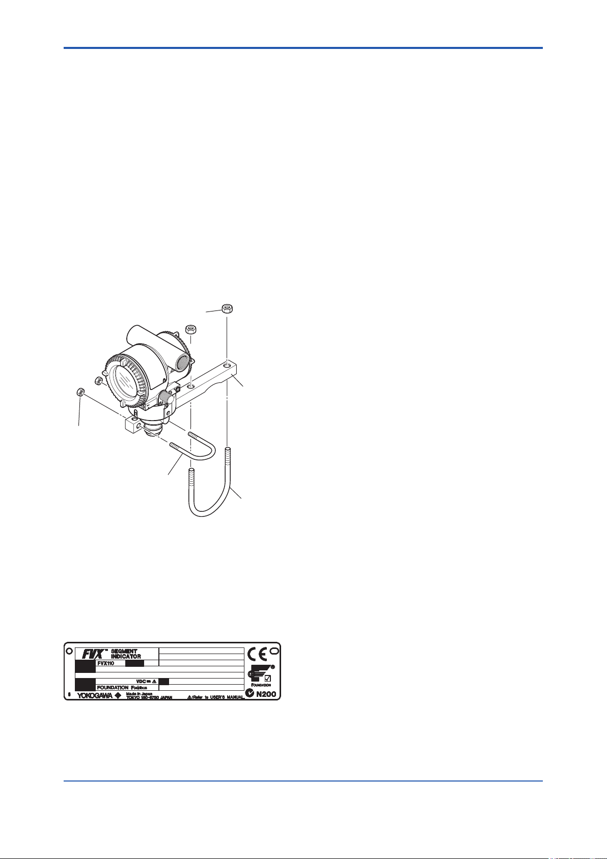
Also check that all indicator mounting hardware
shown in gure 2.1 is included. If the indicator is
ordered without the mounting bracket the indicator
mounting hardware will not be included. After
checking the indicator, carefully repack it in its box
and keep it there until you are ready to install it.
U-bolt nut (L)
Mounting bracket
U-bolt nut (S)
U-bolt (S)
U-bolt (L)
F0201.ai
Figure 2.1 Indicator Mounting Hardware
2.1 Model and Specications
Check
The model name and specications are written on
the name plate attached to the case.
MODEL
SUFFIX
SUPPLY
OUTPUT
Figure 2.2 Name Plate
STYLE
NO.
F0202.ai
2.2 Unpacking
Keep the indicator in its original packaging to
prevent it from being damaged during shipment.
Do not unpack the indicator until it reaches the
installation site.
2.3 Storage
The following precautions must be observed when
storing the instrument, especially for a long period.
(a) Select a storage area which meets the following
conditions:
• It is not exposed to rain or subject to water
seepage/leaks.
• Vibration and shock are kept to a minimum.
• It has an ambient temperature and relative
humidity within the following ranges.
Storage ambient temperature:
–30 to 80°C
Relative humidity:
0% to 100% R.H.
Preferred temperature and humidity:
approx. 25°C and 65% R.H.
(b) When storing the indicator, repack it carefully
in the packaging that it was originally shipped
with.
2.4 Selecting the Installation Location
The indicator is designed to withstand severe
environmental conditions. However, to ensure
that it will provide years of stable and accurate
performance, take the following precautions when
selecting the installation location.
(a) Ambient Temperature
Avoid locations subject to wide temperature
variations or a signicant temperature gradient.
If the location is exposed to radiant heat from
plant equipment, provide adequate thermal
insulation and/or ventilation.
(b) Ambient Atmosphere
Do not install the indicator in a corrosive
atmosphere. If this cannot be avoided, there
must be adequate ventilation as well as
measures to prevent the leaking of rain water
and the presence of standing water in the
conduits.
IM 01S01C01-01EN
Page 12

<2. Handling Cautions>
2-2
(c) Shock and Vibration
Although the indicator is designed to be
relatively resistant to shock and vibration, an
installation site should be selected where this is
kept to a minimum.
(d) Installation of Explosion-protected Indicators
An explosion-protected indicators is certied
for installation in a hazardous area containing
specic gas types. See subsection 2.8
“Installation of an Explosion-Protected
Indicators.”
2.5 Waterproong of Cable
Conduit Connections
Apply a non-hardening sealant to the threads to
waterproof the indicator cable conduit connections.
(See gure 5.2, 5.3 and 5.4.)
2.6 Restrictions on Use of Radio Transceivers
IMPORTANT
Although the indicator has been designed to
resist high frequency electrical noise, if a radio
transceiver is used near the indicator or its
external wiring, the indicator may be affected by
high frequency noise pickup. To test this, start
out from a distance of several meters and slowly
approach the indicator with the transceiver
while observing the measurement loop for noise
effects. Thereafter use the transceiver outside
the range where the noise effects were rst
observed.
2.7 Insulation Resistance and Dielectric Strength Test
Since the indicator has undergone insulation
resistance and dielectric strength tests at the factory
before shipment, normally these tests are not
required. If the need arises to conduct these tests,
heed the following:
(a) Do not perform such tests more frequently than
is absolutely necessary. Even test voltages that
do not cause visible damage to the insulation
may degrade the insulation and reduce safety
margins.
(b) Never apply a voltage exceeding 500 V DC
(100 V DC with an internal lightning protector)
for the insulation resistance test, nor a voltage
exceeding 500 V AC (100 V AC with an internal
lightning protector) for the dielectric strength
test.
(c) Before conducting these tests, disconnect all
signal lines from the indicator terminals. The
procedure for conducting these tests is as
follows:
• Insulation Resistance Test
1) Short-circuit the + and – SUPPLY terminals in
the terminal box.
2) Turn OFF the insulation tester. Then connect
the insulation tester plus (+) lead wire to the
shorted SUPPLY terminals and the minus (–)
leadwire to the grounding terminal.
3) Turn ON the insulation tester power and
measure the insulation resistance. The voltage
should be applied as briey as possible to verify
that the insulation resistance is at least 20 MΩ.
4) After completing the test and being very careful
not to touch exposed conductors disconnect the
insulation tester and connect a 100 kΩ resistor
between the grounding terminal and the shortcircuiting SUPPLY terminals. Leave this resistor
connected at least one second to discharge any
static potential. Do not touch the terminals while
it is discharging.
• Dielectric Strength Test
1) Short-circuit the + and – SUPPLY terminals in
the terminal box.
2) Turn OFF the dielectric strength tester. Then
connect the tester between the shorted
SUPPLY terminals and the grounding terminal.
Be sure to connect the grounding lead of the
dielectric strength tester to the ground terminal.
3) Set the current limit on the dielectric strength
tester to 10 mA, then turn ON the power and
gradually increase the test voltage from ‘0’ to
the specied voltage.
4) When the specied voltage is reached, hold it
for one minute.
5) After completing this test, slowly decrease the
voltage to avoid any voltage surges.
IM 01S01C01-01EN
Page 13

<2. Handling Cautions>
2-3
2.8 Installation of an ExplosionProtected Instrument
If a customer makes a repair or modication to
an intrinsically safe or explosionproof instrument
and the instrument is not restored to its original
condition, its intrinsically safe or explosionproof
construction may be compromised and the
instrument may be hazardous to operate. Please
contact Yokogawa before making any repair or
modication to an instrument.
CAUTION
This instrument has been tested and certied
as being intrinsically safe or explosionproof.
Please note that severe restrictions apply to this
instrument’s construction, installation, external
wiring, maintenance and repair. A failure to abide
by these restrictions could make the instrument a
hazard to operate.
WARNING
Maintaining the safety of explosionproof
equipment requires great care during mounting,
wiring, and piping. Safety requirements also
place restrictions on maintenance and repair.
Please read the following sections very carefully.
2.8.1 FM approval
a. FM Explosionproof Type
Caution for FM Explosionproof type
Note 1. FVX110 Fieldbus Segment Indicator with
optional code /FF1 is applicable for use in
hazardous locations:
• Applicable Standard: FM3600, FM3615,
FM3810, ANSI/NEMA 250
• Explosionproof for Class I, Division 1,
Groups B, C and D.
• Dust-ignitionproof for Class II/III, Division 1,
Groups E, F and G.
• Enclosure rating: NEMA 4X.
• Temperature Class: T6
• Ambient Temperature: –40* to 60ºC
* –15ºC when O-ring material is Fluoro-rubber.
• Supply Voltage: 32V dc max.
• Current Draw: 15 mA
Note 2. Wiring
• All wiring shall comply with National Electrical
Code ANSI/NFPA70 and Local Electrical
Codes.
• When installed in Division 1, “FACTORY
SEALED, CONDUIT SEAL NOT
REQUIRED.”
Note 3. Operation
• Keep the “WARNING” nameplate attached to
the indicator.
WARNING: OPEN CIRCUIT BEFORE
REMOVING COVER. FACTORY SEALED,
CONDUIT SEAL NOT REQUIRED. INSTALL
IN ACCORDANCE WITH THE USERS
MANUAL IM 01S01C01.
• Take care not to generate mechanical
sparking when accessing the instrument and
peripheral devices in a hazardous location.
Note 4. Maintenance and Repair
• The instrument modication or parts
replacement by other than authorized
representative of Yokogawa Electric
Corporation is prohibited and will void
Factory Mutual Explosionproof Approval.
IM 01S01C01-01EN
Page 14
<2. Handling Cautions>
2-4
b. FM Intrinsically safe and Nonincendive
Type
FVX110 Fieldbus Segment Indicator with
optional code /FS15.
Applicable standard: FM3600, FM3610,
•
FM3611, FM3810, ANSI/NEMA250,
ISA60079-27
• FM Intrinsically Safe Approval
[Entity Model]
Class I, II & III, Division 1, Groups A, B, C, D,
E, F & G, Temperature Class T4 Ta=60ºC,
Type 4X and Class I, Zone 0, AEx ia IIC,
Temperature Class T4 Ta=60ºC, Type 4X
[FISCO Model]
Class I, II & III, Division 1, Groups A, B, C, D,
E, F & G, Temperature Class T4 Ta=60ºC,
Type 4X and Class I, Zone 0, AEx ia IIC,
Temperature Class T4 Ta=60ºC, Type 4X
• Nonincendive Approval
Class I, Division 2, Groups A, B, C & D
Temperature Class T4 Ta=60ºC, Type 4X
and Class II, Division 2, Groups F & G
Temperature Class T4 Ta=60ºC, Type 4X
and Class I, Zone 2, Group IIC, Temperature
Class T4 Ta=60ºC, Type 4X and Class III,
Division 1, Temperature Class T4 Ta=60ºC,
Type 4X
• Electrical Connection: 1/2 NPT female, M20
female
• Caution for FM Intrinsically safe type.
(Following contents refer to “DOC. No.
IFM040-A11 p.1 to p.6.”)
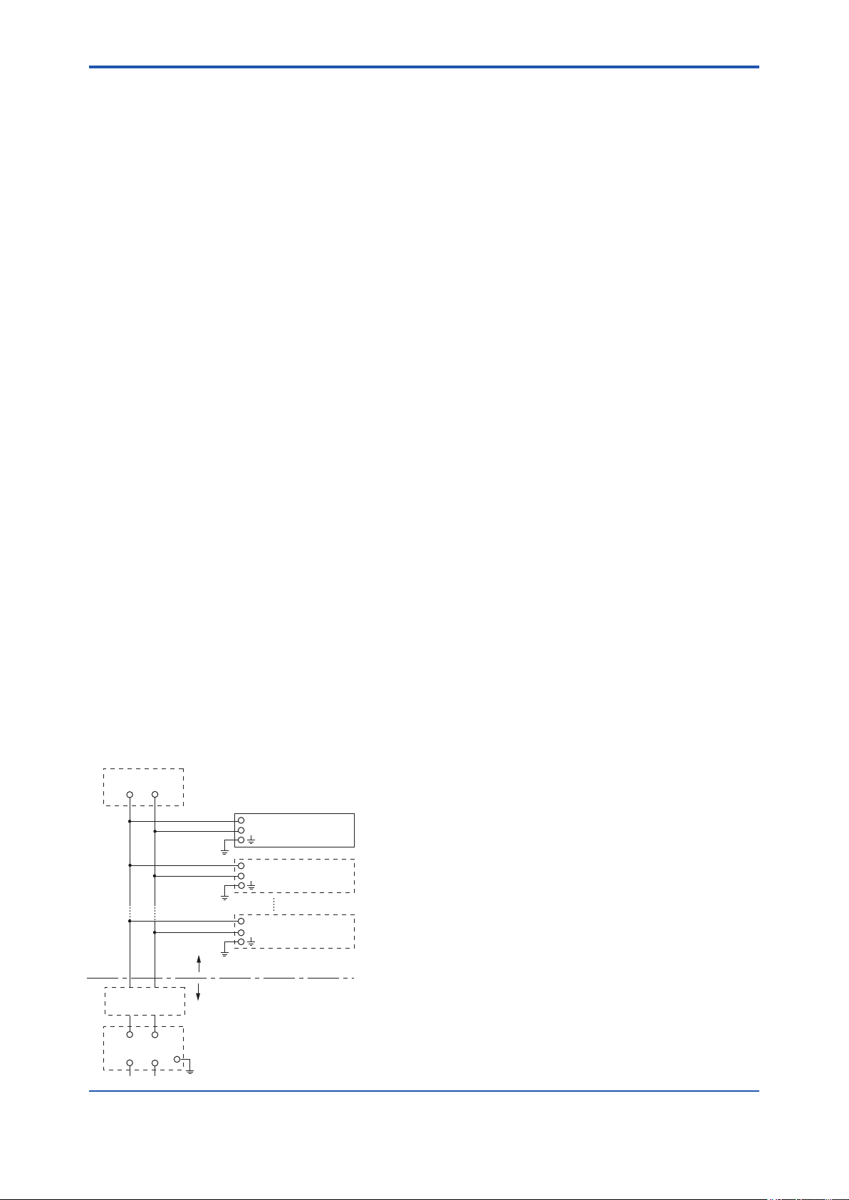
■ IFM040-A11
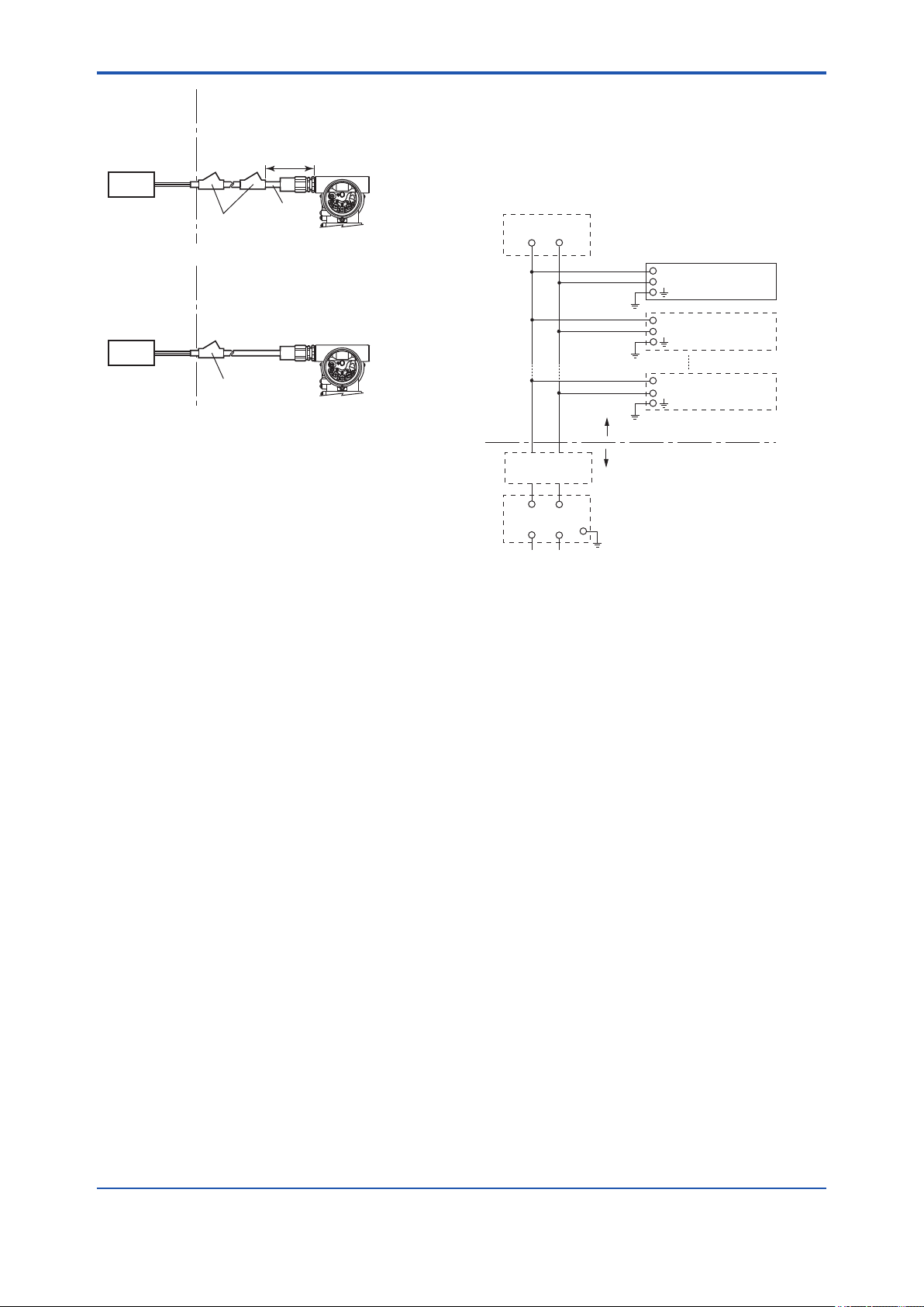
● Installation Diagram for Intrinsically safe
(Division 1 Installation)
Terminator
+
Indicator
–
+
Field Instruments
–
+
Field Instruments
–
Hazardous Location
Terminator
+
Safety Barrier
+
–
–
Non-Hazardous Location
F0203.ai
Note 1. Barrier must be installed in an enclosure
that meets the requirements of ANSI/ISA
61010-1.
Note 2. Control equipment connected to the Associ
ated Apparatus must not use or generate
more than 250 Vrms or Vdc.
Note 3. Installation should be in accordance
with ANSI/ISA 12.06.01 “Installation of
Intrinsi cally Safe Systems for Hazardous
(Classied) Locations” and the National
Electrical Code (ANSI/NFPA 70) Sections
504 and 505.
Note 4. The conguration of Associated Apparatus
must be Factory Mutual Research
Approved under FISCO Concept.
Note 5. Associated Apparatus manufacturer’s
installa tion drawing must be followed
when installing this equipment.
Note 6. No revision to drawing without prior
Factory Mutual Research Approval.
Note 7. Terminator must be FM Approved.
Note 8. Note a warning label worded “SUBSTITU
TION OF COMPONENTS MAY IMPAIR
INTRINSIC SAFETY”, and “INSTALL IN
ACCORDANCE DOC.NO.IFM040-A11 P.1
to P.6.”
Electrical Data:
• Rating 1 (Entity)
For Groups A, B, C, D, E, F, and G or Group IIC
Maximum Input Voltage Vmax: 24 V
Maximum Input Current Imax: 250 mA
Maximum Input Power Pmax: 1.2 W
Maximum Internal Capacitance Ci: 1.76 nF
Maximum Internal Inductance Li: 0 mH
or
• Rating 2 (FISCO)
For Groups A, B, C, D, E, F, and G or Group IIC
Maximum Input Voltage Vmax: 17.5 V
Maximum Input Current Imax: 500 mA
Maximum Input Power Pmax: 5.5 W
Maximum Internal Capacitance Ci: 1.76 nF
Maximum Internal Inductance Li: 0 mH
or
• Rating 3 (FISCO)
For Groups C, D, E, F, and G or Group IIB
Maximum Input Voltage Vmax: 17.5 V
Maximum Input Current Imax: 500 mA
Maximum Input Power Pmax: 5.5 W
Maximum Internal Capacitance Ci: 1.76 nF
Maximum Internal Inductance Li: 0 mH
IM 01S01C01-01EN
Page 15

<2. Handling Cautions>
2-5
Note: In the rating 1, the output current of the barrier must
be limited by a resistor “Ra” such that Io=Uo/Ra. In the
rating 2 or 3, the output characteristics of the barrier
must be the type of trapezoid which are certied as
the FISCO model (See “FISCO Rules”). The safety
barrier may include a terminator. More than one eld
instruments may be connected to the power supply
line.
● FISCO Rules
The FISCO Concept allows the interconnection
of intrinsincally safe apparatus to associated
apparatus not specically examined in such
combination. The criterion for such interconnection
is that the voltage (Ui), the current (Ii) and the power
(Pi) which intrinsically safe apparatus can receive
and remain intrinsically safe, considering faults,
must be equal or greater than the voltage (Uo,
Voc, Vt), the current (Io, Isc, It) and the power (Po)
which can be provided by the associated apparatus
(supply unit).
Po ≤ Pi, Uo ≤ Ui, Io ≤ Ii
In addition, the maximum unprotected residual
capacitance (Ci) and inductance (Li) of each
apparatus (other than the terminators) connected to
the eldbus must be less than or equal to 5 nF and
10 µH respectively.
Ci ≤ 5nF, Li ≤ 10µH
In each I.S. eldbus segment only one active
source, normally the associated apparatus, is
allowed to provide the necessary power for the
eldbus system. The allowed voltage(Uo, Voc,Vt)
of the associated apparatus used to supply the
bus cable must be limited to the range of 14 V dc
to 17.5 V dc. All other equipment connected to
the bus cable has to be passive, meaning that the
apparatus is not allowed to provide energy to the
system, except to a leakage current of 50 µA for
each connected device.
Supply unit
Trapezoidal or rectangular output characteristic only
Uo = 14...17.5 V (I.S. maximum value)
Io according to spark test result or other
assessment. No specication of Lo and Co is
required on the certicate or label.
Cable
The cable used to interconnect the devices needs
to comply with the following parameters:
Loop resistance R': 15...150 Ω/km
Inductance per unit length L': 0.4...1 mH/km
Capacitance per unit length C': 45...200 nF/km.
C'=C' line/line + 0.5 C' line/screen, if both lines
are oating or C'=C' line/line + C' line/screen, if
the screen is connected to one line.
Length of spur cable: max. 60 m
Length of trunk cable: max. 1 km (Group IIC) or
5 km (Group IIB)
Length of splice: max.1m
Terminators
At each end of the trunk cable an FM approved line
terminator with the following parameters is suitable:
R = 90...100 Ω
C = 0...2.2 mF
System evaluations
The number of passive device like transmitters,
actuators, hand held terminals connected to
a single bus segment is not limited due to I.S.
reasons. Furthermore, if the above rules are
respected, the inductance and capacitance of the
cable need not to be considered and will not impair
the intrinsic safety of the installation.
SAFE AREAHAZARDOUS AREA
Terminator
(FISCO Model)
Ex i
Hand-
held-
Terminal
Field Instruments
(Passive)
I.S. eldbus system complying with FISCO model
Supply Unit and
Safety Barrier
(FISCO Model)
U
I
Terminator
Data
F0204.ai
U
IM 01S01C01-01EN
Page 16
<2. Handling Cautions>
2-6
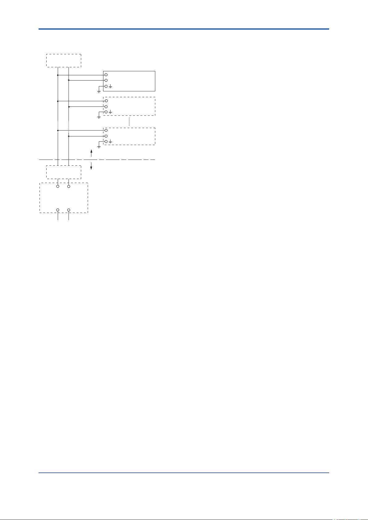
● Installation Diagram for Nonincendive
(Division 2 Installation)
Terminator
+
Indicator
–
+
Field Instruments
–
+
Field Instruments
–
Hazardous Location
Non-Hazardous Location
Terminator
FM Approved
+ –
General Purpose
Equipment
+ –
Associated Nonincendive Field
Wiring Apparatus
Vt or Voc
It or Isc
Ca
La
F0205.ai
Note 1. Installation should be in accordance with
the National Electrical Code ® (ANSI/NFPA
70) Article 500.
Note 2. The conguration of Associated
Nonincendive Field Wiring Apparatus must
be FM Approved.
Note 3. Approved under FNICO Concept.
Note 4. Dust-tight conduit seal must be used
when installed in Class II and Class III
environments.
Note 5. Associated Apparatus manufacturer’s
installation drawing must be followed when
installing this apparatus.
Note 6. No revision to drawing without prior FM
Approvals.
Note 7. Terminator must be FM Approved.
Note 8. The nonincendive eld wiring circuit
concept allows interconection of
nonincendive eld wiring apparatus with
associated nonincendive eld wiring
apparatus, using any of the wiring methods
permitted for unclassied locations.
Note 9. Installation requirements;
Vmax ≥ Voc or Vt
Imax = see note 10.
Ca ≥ Ci + Ccable
La ≥ Li + Lcable
Note 10. For this current controlled circuit, the
parameter (Imax) is not required and need
not be aligned with parameter (Isc) of the
barrier or associated nonincendive eld
wiring apparatus.
Note 11. If ordinary location wiring methods are
used, indicator and eld instruments shall
be connected to FM Approved associated
nonincendive eld wiring apparatus.
Electrical data:
Vmax: 32 V
Ci: 1.76 nF
Li: 0 µH
● FNICO Rules
The FNICO Concept allows the interconnection of
nonincendive eld wiring apparatus to associated
nonincendive eld wiring apparatus not specically
examined in such combination. The criterion for
such interconnection is that the voltage (Vmax),
the current (Imax) and the power (Pmax) which
nonincendive eld wiring apparatus can receive and
remain nonincendive, considering faults, must be
equal or greater than the voltage (Uo, Voc or Vt),
the current (Io, Isc or It) and the power (Po) which
can be provided by the associated nonincendive
eld wiring apparatus (supply unit). In addition the
maximum unprotected residual capacitance (Ci)
and inductance (Li) of each apparatus (other than
terminators) connected to the Fieldbus must be less
than or equal to 5nF and 20uH respectively.
In each N.I. Fieldbus segment only one active
source, normally the associated nonincendive
eld wiring apparatus, is allowed to provide the
necessary power for the Fieldbus system. The
allowed voltage (Uo, Voc or Vt) of the associated
nonincendive eld wiring apparatus used to supply
the bus cable must be limited to the range 14Vdc
to 17.5Vdc. All other equipment connected to the
bus cable has to be passive, meaning that the
apparatus is not allowed to provide energy to the
system, except a leakage current of 50 µA for each
connected device. Separately powered equipment
needs galvanic isolation to ensure the nonincendive
eld wiring Fieldbus circuit remains passive.
IM 01S01C01-01EN
Page 17

<2. Handling Cautions>
2-7
Cable
The cable used to interconnect the devices needs
to comply with the following parameters:
Loop resistance R': 15...150 Ω/km
Inductance per unit length L': 0.4...1 mH/km
Capacitance per unit length C': 45....200 nF/km
C' =C' line/line+0.5 C' line/screen, if both lines
are oating or C' = C' line/line + C' line/screen, if
the screen is connected to one line.
Length of spur cable: max. 60 m
Length of trunk cable: max. 1 km (Group IIC) or
5 km (Group IIB)
Length of splice: max = 1 m
Terminators
At the end of each trunk cable an FM Approved line
terminator with the following parameters is suitable:
R= 90...100 Ω
C = 0 ....2.2 mF
2.8.2 CSA Certication
a. CSA Explosionproof Type
Caution for CSA explosionproof type.
Note 1. FVX110 Fieldbus Segment Indicator with
optional code /CF1 is applicable for use in
hazardous locations:
Certicate: 2325751
• Applicable Standard:
C22.2 No.0, C22.2 No.0.4, C22.2 No.0.5,
C22.2 No.25, C22.2 No.30, C22.2 No.94,
C22.2 No.213, C22.2 No.61010-01-04,
C22.2 No.60079-0, C22.2 No.60079-1
[For CSA C22.2]
• Explosion-proof for Class I, Groups B, C and
D.
• Dustignition-proof for Class II/III, Groups E, F
and G.
• Enclosure: TYPE 4X
• Temperature Code: T6
[For CSA E60079]
• Flameproof for Zone 1, Ex d IIC T6
• Enclosure: IP66 and IP67
• Ambient Temperature: –50* to 75ºC (T6)
* –15ºC when O-ring material is Fluoro-rubber.
• Supply Voltage: 32 V dc max.
• Output Signal: 15 mA
Note 2. Wiring
• All wiring shall comply with Canadian
Electrical Code Part I and Local Electrical
Codes.
• In hazardous location, wiring shall be in
conduit as shown in the gure.
• WARNING:
A SEAL SHALL BE INSTALLED WITHIN
50cm OF THE ENCLOSURE.
UN SCELLEMENT DOIT ÊTRE INSTALLÉÀ
MOINS DE 50cm DU BOîTIER.
• WARNING:
WHEN INSTALLED IN CL.I, DIV 2, SEAL
NOT REQUIRED.
UNE FOIS INSTALLÉ DANS CL I, DIV 2,
AUCUN JOINT N'EST REQUIS.
Note 3. Operation
• WARNING:
AFTER DE-ENERGIZING, DELAY 5
MINUTES BEFORE OPENING.
APRÉS POWER-OFF, ATTENDRE 5
MINUTES AVANT D'OUVRIR.
• WARNING:
WHEN AMBIENT TEMPERATURE ≥ 65ºC,
USE THE HEAT-RESISTING CABLES ≥
90ºC.
QUAND LA TEMPÉRATURE AMBIANTE
≥ 65ºC, UTILISEZ DES CÂBLES
RÉSISTANTES Á LA CHALEUR ≥ 90ºC.
• Take care not to generate mechanical
sparking when accessing to the instrument
and peripheral devices in a hazardous
location.
Note 4. Maintenance and Repair
• The instrument modication or parts
replacement by other than authorized
representative of Yokogawa Electric
Corporation and Yokogawa Corporation of
America is prohibited and will void Canadian
Standards Explosionproof Certication.
IM 01S01C01-01EN
Page 18
<2. Handling Cautions>
2-8
Non-Hazardous
Hazardous Locations Division 1
Locations
Non-hazardous
Location
Equipment
32 V DC Max.
15 mA DC
Signal
Non-Hazardous
Sealing Fitting
Hazardous Locations Division 2
50 cm Max.
Conduit
Segment Indicator
PULSE
PULSE
SUPPLY
SUPPLY
CHECK
CHECK
ALARM
ALARM
Locations
Non-hazardous
Location
Equipment
PULSE
PULSE
SUPPLY
SUPPLY
CHECK
CHECK
ALARM
32 V DC Max.
15 mA DC
Signal
Sealing Fitting
Segment Indicator
ALARM
F0206.ai
b. CSA Intrinsically safe and Nonincendive
Type
FVX110 Fieldbus Segment Indicator with
optional code /CS15.
• Certicate: 2346277
• Applicable standard:
C22.2 No.0, C22.2 No.0.4, C22.2 No.25,
C22.2 No.94, C22.2 No.157, C22.2 No.213,
C22.2 No.61010-1-04, C22.2
CAN/CSA E60079-0, CAN/CSA E60079-11,
CAN/CSA E60079-15, IEC 60529
• CSA Intrinsically Safe Approval
Class I, Division 1, Groups A, B, C, & D;
Class II, Division 1, Groups E, F & G;
Class III Division 1; Ex ia IIC T4
Ambient Temperature: –40* to 60°C (–40* to
140°F) Encl. Type 4X, IP66 and IP67
* –15ºC when O-ring material is Fluoro-rubber.
• CSA Nonincendive Approval
Class I, Division 2, Groups A, B, C, & D;
Class II, Division 2, Groups F & G;
Class III Division 1; Ex nL IIC T4
Ambient Temperature: –40* to 60°C (–40* to
140°F) Encl. Type 4X, IP66 and IP67
* –15ºC when O-ring material is Fluoro-rubber.
● Caution for CSA Intrinsically safe type.
(Following contents refer to “DOC. No.
ICS018”)
Installation Diagram for Intrinsically safe
(Division 1 Installation)
Terminator
+
Indicator
–
+
Field Instruments
–
+
Field Instruments
–
Hazardous Location
Non-Hazardous Location
Terminator
+
–
Safety Barrier
+
–
F0207.ai
Note 1. The safety barrier must be CSA certied.
Note 2. Input voltage of the safety barrier must be
less than 250Vrms/Vdc.
Note 3. Installation should be in accordance with
Canadian Electrical Code Part I and local
Electrical Code.
Note 4. Do not alter drawing without authorization
from CSA.
IM 01S01C01-01EN
Page 19

<2. Handling Cautions>
2-9
Electrical Data:
• Rating 1 (Entity)
For Groups A, B, C, D, E, F, and G or Group
IIC
Ui (vmax) = 24 V dc
Ii (Imax) = 250 mA
Pi (Pmax) = 1.2 W
Ci = 1.76 nF
Li = 0 mH
or
• Rating 2 (FISCO)
For Groups A, B, C, D, E, F, and G or Group
IIC
Ui (vmax) = 17.5 V dc
Ii (Imax) = 500 mA
Pi (Pmax) = 5.5 W
Ci = 1.76 nF
Li = 0 mH
or
• Rating 3 (FISCO)
For Groups C, D, E, F, and G or Group IIB
Ui (vmax) = 17.5 V dc
Ii (Imax) = 500 mA
Pi (Pmax) = 5.5 W
Ci = 1.76 nF
Li = 0 mH
Installation requirements;
Po ≤ Pi Uo ≤ Ui Io ≤ Ii,
Co ≥ Ci + Ccable Lo ≥ Li + Lcable
Vmax ≥ Voc Imax ≥ Isc
Ca ≥ Ci + Ccable La ≥ Li + Lcable
Uo, Io, Po, Co, Lo,Voc, Isc, Ca and La are
parameters of barrier.
● Caution for CSA Non-incendive type.
(Following contents refer to “DOC. No.
ICS018”)
Installation Diagram for Non-incendive
or Type of protection "n" (Division 2
Installation)
Terminator
+
Indicator
–
+
Field Instruments
–
+
Field Instruments
–
Hazardous Location
Non-Hazardous Location
Terminator
+ –
CSA Certified
Equipment [nL]
+ –
F0208.ai
Note 1. Installation should be in accordance with
Canadian Electrical Code Part I and local
Electrical Code.
Note 2. Dust-tight conduit seal must be used when
installed in class II and III environments.
Note 3. Do not alter drawing without authorization
from CSA.
Electrical Data:
• Rating (including FNICO)
Ui or Vmax = 32 V
Ci = 1.76 nF
Li = 0 mH
IM 01S01C01-01EN
Page 20

<2. Handling Cautions>
2-10
2.8.3 CENELEC ATEX Certication
(1) Technical Data
a. CENELEC ATEX (DEKRA) Intrinsically Safe
Type
Caution for CENELEC ATEX (DEKRA)
Intrinsically safe type.
Note 1. FVX110 Fieldbus Segment Indicator
with optional code /KS25 for potentially
explosive atmospheres:
• No. DEKRA 11ATEX0022 X
• Applicable Standard: EN 60079-0:2009,
EN 60079-11:2007, EN 60079-26:2007,
EN 60079-27:2008, EN 61241-11:2006
Note 2. Ratings
Type of Protection and Marking Code:
II1G Ex ia IIB/IIC T4 Ga
II1D Ex ia IIIC T80ºC Da IP6X
Group: II
Category: 1G 1D
Ambient Temperature: –40* to 60ºC
* –15ºC when O-ring material is Fluoro-rubber.
Maximum Surface Temperature for dust-proof.
T80ºC (Tamb.: –40* to 60ºC)
* –15ºC when O-ring material is Fluoro-rubber.
Degree of Protection of the Enclosure:
IP66 and IP67
Electrical Data
• When combined with Trapezoidal output
characteristic FISCO model IIC or IIB barrier
[Supply/Output circuit (terminals + and –)]
Ui = 17.5 V, Ii = 500 mA, Pi = 5.5 W,
Ci = 3.52 nF, Li = 0 µH
• When combined with Linear characteristic
barrier
[Supply/Output circuit (terminals + and –)]
Ui = 24.0 V, Ii = 250 mA, Pi = 1.2 W,
Ci = 3.52 nF, Li = 0 µH
Note 3. Installation
• All wiring shall comply with local installation
requirements. (Refer to the installation
diagram)
Note 4. Maintenance and Repair
• The instrument modication or parts
replacement by other than authorized
representative of Yokogawa Electric
Corporation is prohibited and will void
DEKRA Intrinsically safe Certication.
Note 5. Special Conditions for Safe Use
• In the case where the enclosure of the
segment indicator is made of aluminium, if
it is mounted in an area where the use of
category 1 G apparatus is required, it must
be installed such, that even in the event of
rare incidents, ignition sources due to impact
and friction sparks are excluded.
Note 6. Installation instructions
• The test voltage for the isolation between the
intrincically safe supply/output circuit and the
frame of the apparatas for segment indicator
that are provided with surge protection is
limited to 90 V, due to the presence of the
surge protection device only.
When used in a potentially explosive
atmosphere, requiring the use of apparatus
of equipment category 1D or 2D, certied
cable entry devices shall be used that are
suitable for the application and correctly
installed.
● FISCO Model
Non-Hazardous
Locations
Supply Unit and
Safety Barrier
(FISCO Model)
U
U
I
Terminator
Data
I.S. eldbus system complying with FISCO
Hazardous Locations
Terminator
(FISCO Model)
Ex i
Hand-
held-
Terminal
Field Instruments
(Passive)
F0209.ai
IM 01S01C01-01EN
Page 21

<2. Handling Cautions>
2-11
The criterion for such interconnection is that the
voltage (Ui), the current (Ii) and the power (Pi),
which intrinsically safe apparatus can receive,
must be equal or greater than the voltage (Uo),
the current (Io) and the power (Po) which can be
provided by the associated apparatus (supply unit).
Po ≤ Pi, Uo ≤ Ui, Io ≤ Ii
In addition, the maximum unprotected residual
capacitance (Ci) and inductance (Li) of each
apparatus (other than the terminators) connected
to the eldbus line must be equal or less than 5 nF
and 10 µH respectively.
Ci ≤ 5 nF, Li ≤ 10 µH
Supply unit
The supply unit must be certied by a Notied
body as FISCO model and following trapezoidal or
rectangular output characteristic is used.
Uo = 14...17.5 V (I.S. maximum value)
Io based on spark test result or other assessment,
No specication of Lo and Co is required on the
certicate or label.
Cable
The cable used to interconnect the devices needs
to comply with the following parameters:
● Entity Model
Non-Hazardous
Locations
Supply Unit and
Safety Barrier
U
U
I
Terminator
Data
I.S. eldbus system complying with Entity model
Hazardous Locations
Ex i
Hand-
held-
Terminal
Field Instruments
(Passive)
Terminator
F0210.ai
I.S. values Power supply-eld device:
Po ≤ Pi, Uo ≤ Ui, Io ≤ Ii
Calculation of max. allowed cable length:
Ccable ≤ Co – ∑Ci – ∑Ci (Terminator)
Lcable ≤ Lo – ∑Li
Number of Devices
The number of devices (max. 32) possible on a
eldbus link depends on factors such as the power
consumption of each device, the type of cable used,
use of repeaters, etc.
Loop resistance Rc: 15...150 Ω/km
Inductance per unit length Lc: 0.4...1 mH/km
Capacitance per unit length Cc: 45...200 nF/km
Length of spur cable: max. 60 m (IIC and IIB)
Length of trunk cable: max. 1 km (IIC) or 5 km
(IIB)
Terminators
The terminator must be certied by a Notied body
as FISCO model and at each end of the trunk
cable an approved line terminator with the following
parameters is suitable:
R = 90 . . . 102 Ω
C = 0 . . . 2.2 µF. (0.8...1.2 µF is required in
operation)
The resistor must be infallible according to IEC
60079-11.
Number of Devices
The number of devices (max. 32) possible on a
eldbus link depends on factors such as the power
consumption of each device, the type of cable used,
use of repeaters, etc.
b. CENELEC ATEX (KEMA) Flameproof Type
Caution for CENELEC ATEX (KEMA)
ameproof type
Note 1. FVX110 Fieldbus Segment Indicator
with optional code /KF25 for potentially
explosive atmospheres:
• No. KEMA 10ATEX0157
• Applicable Standard:
EN 60079-0:2006, EN 60079-1:2004,
EN 61241-0:2006, EN 61241-1:2004
• Type of Protection and Marking Code:
Ex d IIC T6, Ex tD A21 IP6x T80
• Group: II
• Category: 2G, 2D
• Temperature Class: T6
• Enclosure: IP66 and IP67
• Ambient Temperature for gas-proof:
–50* to 75ºC (T6)
* –15ºC when O-ring material is Fluoro-rubber.
• Maximum Surface Temperature for dustproof:
T80ºC (Tamb.: –40* to 75ºC)
* –15ºC when O-ring material is Fluoro-rubber.
IM 01S01C01-01EN
Page 22
<2. Handling Cautions>
2-12
Note 2. Electrical Data
• Supply voltage: 32 V dc max.
Output current: 15 mA dc
Note 3. Installation
• All wiring shall comply with local installation
requirements.
• The cable entry devices shall be of a certied
ameproof type, suitable for the conditions of
use.
Note 4. Operation
• Keep the “WARNING” label attached to the
indicator.
WARNING: AFTER DE-ENERGIZING,
DELAY 5 MINUTES BEFORE OPENING.
WHEN THE AMBIENT TEMP.≥65ºC, USE
HEAT-RESISTING CABLES≥90ºC.
• Take care not to generate mechanical
sparking when accessing the instrument and
peripheral devices in hazardous location.
Note 5. Maintenance and Repair
• The instrument modication or part
replacement by other than an authorized
representative of Yokogawa Electric
Corporation is prohibited and will void KEMA
Flameproof Certication.
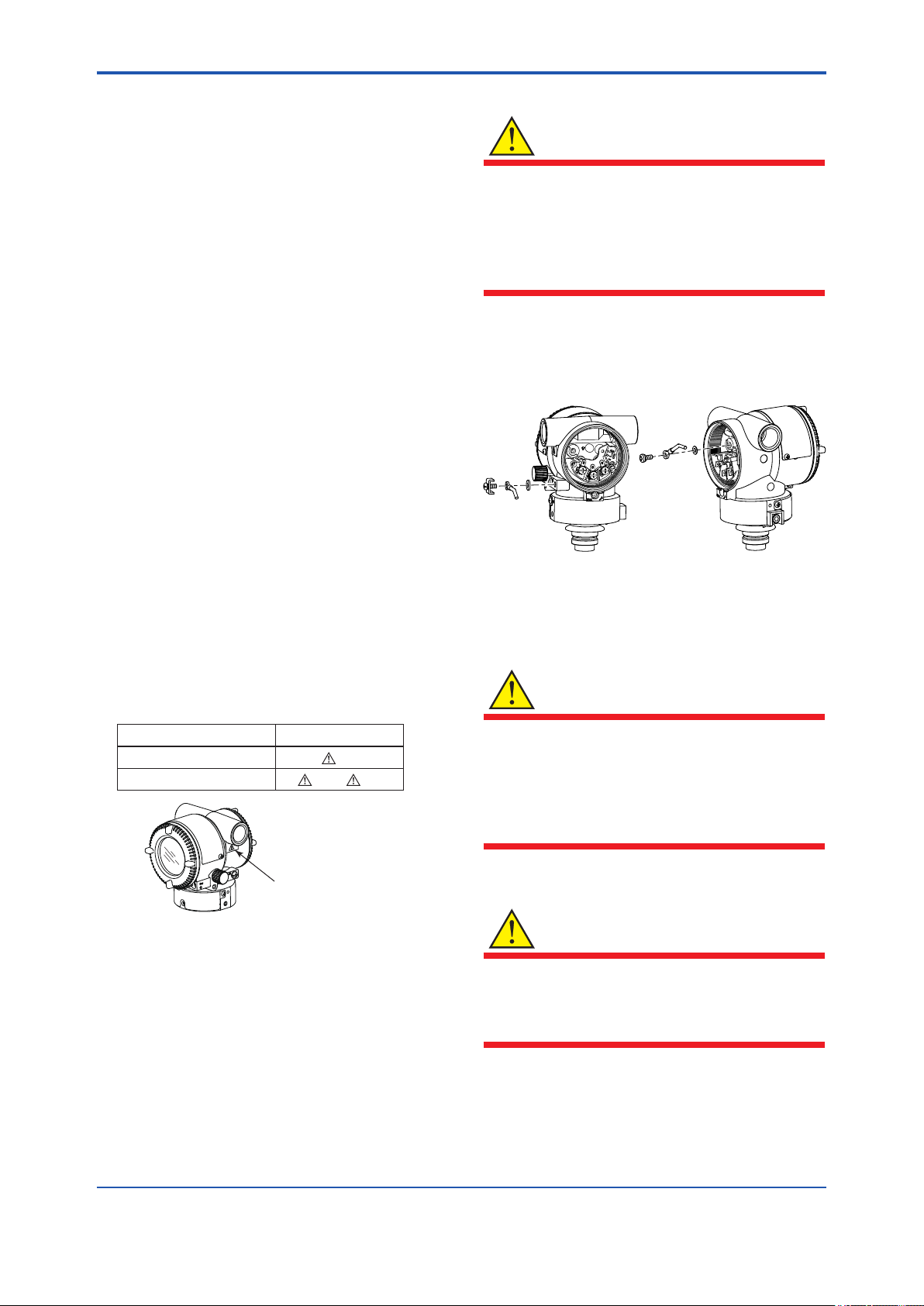
(2) Electrical Connection
A mark indicating the electrical connection type is
stamped near the electrical connection port. These
marks are as follows.
(3) Installation
WARNING
• All wiring shall comply with local installation
requirements and the local electrical code.
• There is no need for a conduit seal in
Division 1 and Division 2 hazardous
locations because this product is sealed at
the factory.
The grounding terminals are located on the inside
and outside of the terminal area.
Connect the cable to grounding terminal in
accordance with wiring procedure 1) or 2).
1) External grounding
terminal
Wiring Procedure for Grounding Terminals
2) Internal grounding
terminal
F0212.ai
(4) Operation
WARNING
ISO M20×1.5 female
ANSI 1/2 NPT female
MarkingScrew Size
M
A or W
Location of the mark
F0211.ai
• OPEN CIRCUIT BEFORE REMOVING
COVER. INSTALL IN ACCORDANCE WITH
THIS USER’S MANUAL
• Take care not to generate mechanical
sparking when accessing the instrument and
peripheral devices in a hazardous location.
(5) Maintenance and Repair
WARNING
The instrument modication or part replacement
by other than an authorized Representative of
Yokogawa Electric Corporation is prohibited and
will void the certication.
IM 01S01C01-01EN
Page 23
<2. Handling Cautions>
2-13
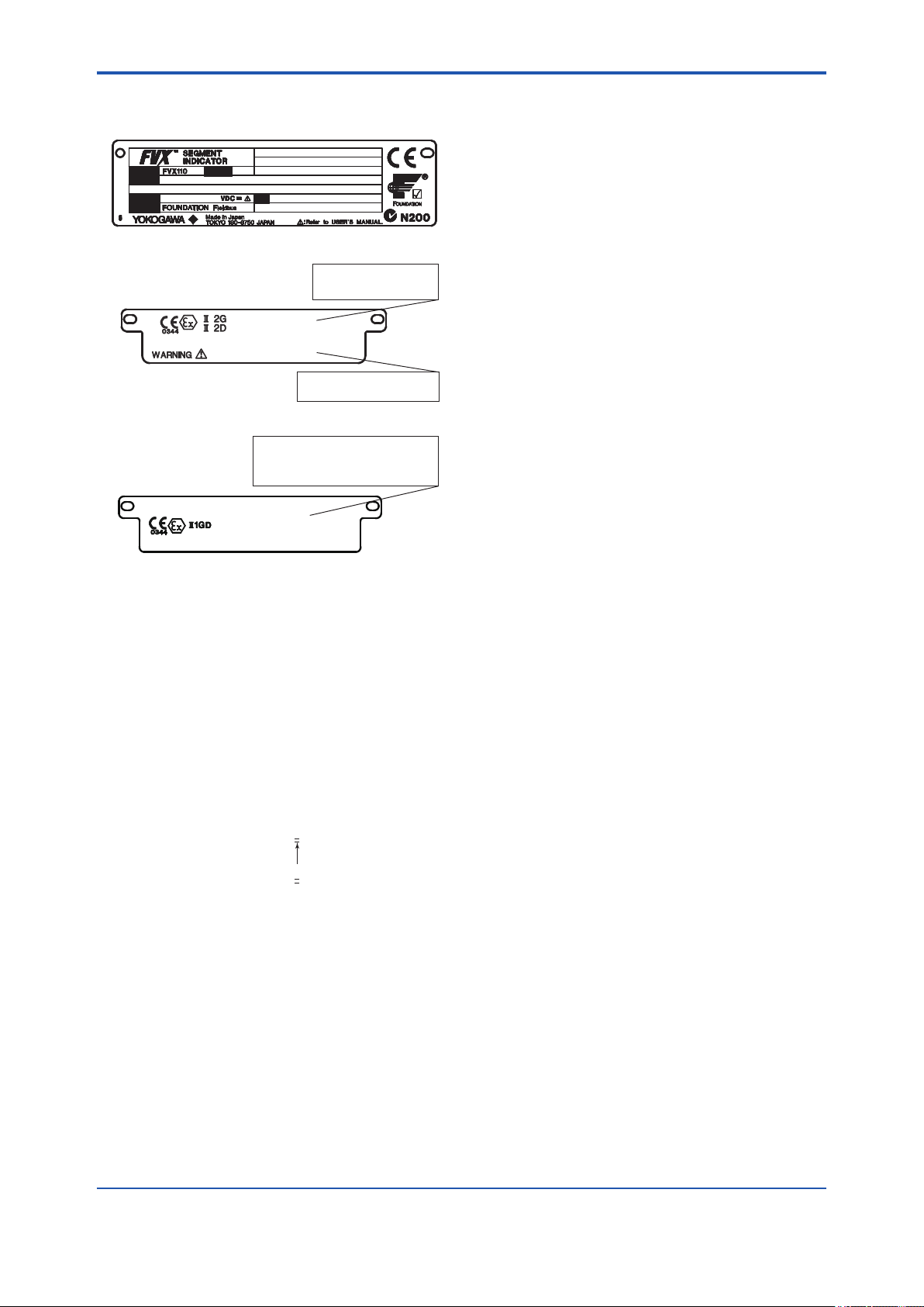
(6) Name Plate
● Name plate
MODEL
SUFFIX
SUPPLY
OUTPUT
STYLE
NO.
● Tag plate for flameproof type
No. KEMA 10ATEX0157
Ex d IIC T6, Ex tD A21, IP6X T80ºC
Enlcosure: IP66, IP67
Tamb.(GAS) -50(-15) to 75 ºC
Tamb.(Dust) -40(-15) to 75 ºC
AFTER DE-ENERGIZING, DELAY 5 MINUTES
BEFORE OPENING.
WHEN THE AMBIENT TEMP. ≥ 65ºC,
USE THE HEAT-RESISTING CABLES ≥ 90ºC
● Tag plate for intrinsically safe type
No. DEKRA 11ATEX0022 X
Ex ia IIB/IIC T4 Ga
Ex ia IIIC T80ºC Da IP6X
Tamb: -40 to 60ºC
ENCLOSURE: IP66/IP67
FISCO Field device
Entity Parameters Ui=24V, Ii=250mA, Pi=1.2W, Ci=3.52nF, Li=0µH
F0213.ai
MODEL: Specied model code.
STYLE: Style code.
SUFFIX: Specied sufx code.
SUPPLY: Supply voltage.
OUTPUT: Output signal.
NO.: Serial number and year of production*1.
TOKYO 180-8750 JAPAN:
The manufacturer name and the address*2.
*1: The rst digit in the nal three numbers of the serial
number appearing after “NO.” on the name plate
indicates the year of production. The following is an
example of a serial number for a product that was
produced in 2010:
91K819857 032
The year 2010
*2: “180-8750” is the Zip code for the following address.
2-9-32 Nakacho, Musashino-shi, Tokyo Japan
2.8.4 IECEx Certication
a. IECEx Flameproof Type
Caution for IECEx ameproof type.
Note 1. FVX110 Fieldbus Segment Indicator with
optional code /SF25 are applicable for use
in hazardous locations:
• No. IECEx KEM10.0071
• Applicable Standard: IEC60079-0(:2004),
IEC60079-1(:2003)
• Type of Protection and Marking Code:
Ex d IIC T6
• Temperature Class: T6
• Enclosure: IP66 and IP67
• Ambient Temperature for gas-proof:
–50* to 75ºC (T6)
* –15ºC when O-ring material is Fluoro-rubber.
Note 2. Wiring
• In hazardous locations, the cable entry
devices shall be of a certied ameproof
type, suitable for the conditions of use and
correctly installed.
• Unused apertures shall be closed with
suitable ameproof certied blanking
elements.
Note 3. Operation
• WARNING:
AFTER DE-ENERGIZING, DELAY 5
MINUTES BEFORE OPENING.
• WARNING:
WHEN AMBIENT TEMPERATURE ≥ 65ºC,
USE THE HEAT-RESISTING CABLES ≥
90ºC.
• Take care not to generate mechanical
sparking when accessing to the instrument
and peripheral devices in a hazardous
location.
Note 4. Maintenance and Repair
• The instrument modication or parts
replacement by other than authorized
representative of Yokogawa Electric
Corporation is prohibited and will void IECEx
Certication.
IM 01S01C01-01EN
Page 24
<2. Handling Cautions>
2-14
b. IECEx Intrinsically Safe Type
Caution for IECEx Intrinsically safe type.
Note 1. FVX110 Fieldbus Segment Indicator with
optional code /SS25 are applicable for use
in hazardous locations:
• No. IECEx DEK 11.0004 X
• Applicable Standard:
IEC60079-0:2007, IEC60079-11:2006,
IEC60079-26:2006, IEC60079-27:2008
Note 2. Ratings
[Ex ia IIB/IIC T4 Ga]
• Type of Protection: II1G Ex ia IIB/IIC T4 Ga
• Ambient Temperature: –40* to 60ºC
* –15ºC when O-ring material is Fluoro-rubber.
• Degree of Protection of the Enclosure:
IP66 and IP67
• When combined with Trapezoidal output
characteristic FISCO model
IIC or IIB barrier
[Supply/Output circuit (terminals + and –)]
Ui = 17.5 V, Ii = 500 mA, Pi = 5.5 W,
Ci = 3.52 nF, Li = 0
• When combined with Linear characteristic
barrier
[Supply/Output circuit (terminals + and –)]
Ui = 24.0 V, Ii = 250 mA, Pi = 1.2 W,
Ci = 3.52 nF, Li = 0
[Ex ic IIC T4 Gc]
• Type of Protection: II3G Ex ic IIC T4 Gc
• Ambient Temperature: –40* to 60ºC
* –15ºC when O-ring material is Fluoro-rubber.
• Degree of Protection of the Enclosure:
IP66 and IP67
[Supply/Output circuit (terminals + and –)]
Ui = 32.0 V, Ci = 3.52 nF, Li = 0
Note 3. Installation
• In any safety barrier used output current
must be limited by a resistor 'R' such that
Io=Uo/R.
• The safety barrier must be IECEx certied.
• Input voltage of the safety barrier must be
less than 250 Vrms/Vdc.
• The instrument modication or parts
replacement by other than authorized
representative of Yokogawa Electric
Corporation and will void IECEx Intrinsically
safe certication.
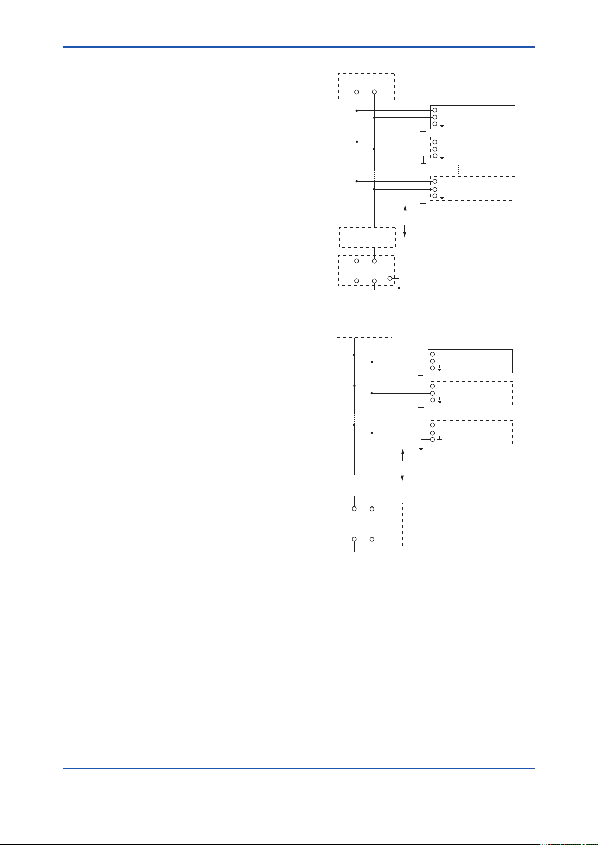
[Intrinsically safe apparatus level of protection “ia”]
Terminator
+
Indicator
−
+
Field Instruments
−
+
Field Instruments
−
Hazardous Location
Terminator
+
Safety Barrier
+
[Intrinsically safe apparatus level of protection “ic”]
Terminator
Terminator
+ −
General Porpose
Equipment
+ −
−
−
Non-Hazardous Location
+
Indicator
−
+
Field Instruments
−
+
Field Instruments
−
Hazardous Location
Non-Hazardous Location
F0214.ai
F0215.ai
IM 01S01C01-01EN
Page 25
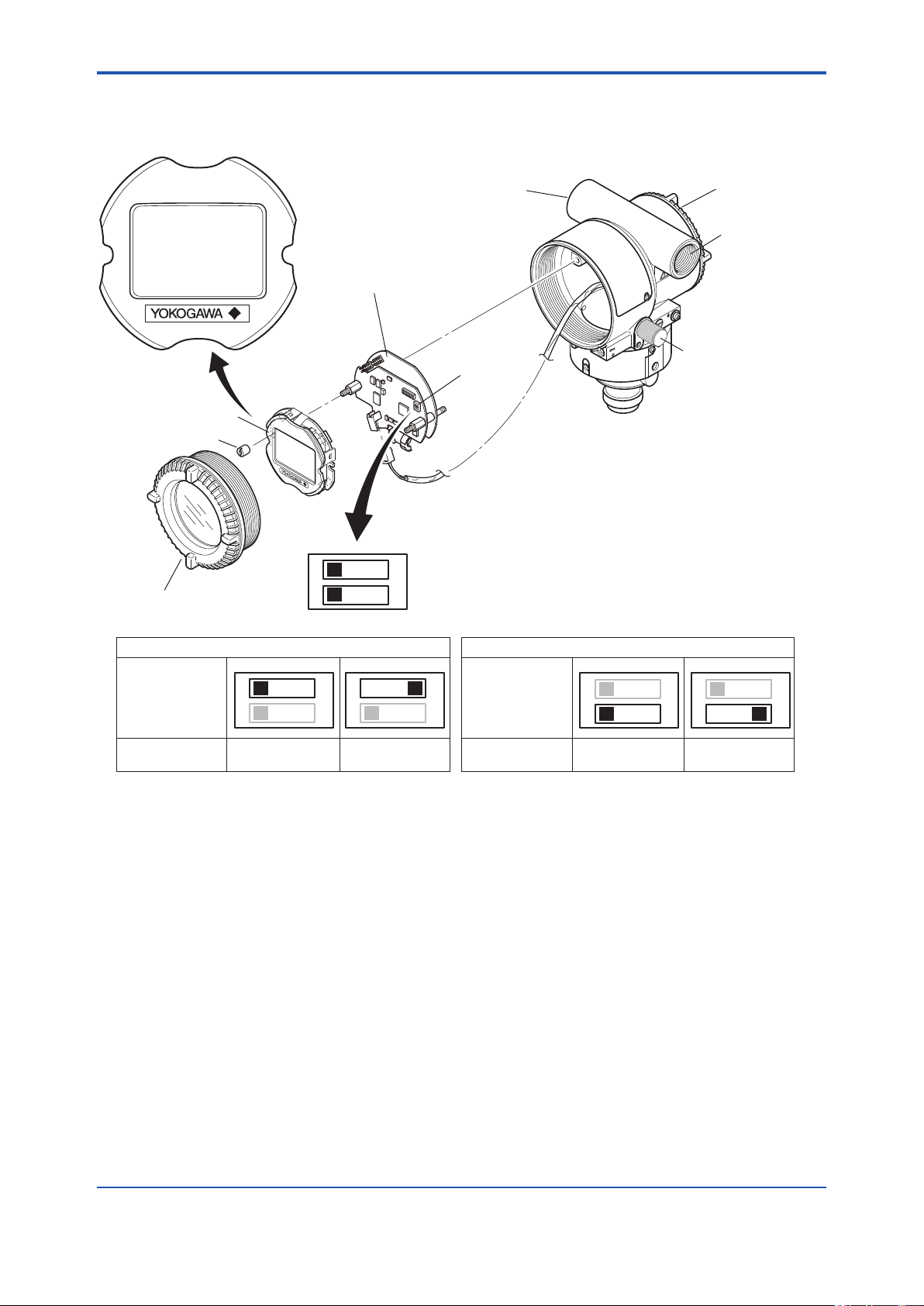
<3. Component Names>
3. Component Names
3-1
Display assembly
Mounting screw
Display cover
CPU assembly
1
2
Conduit connection
Slide switch
O
SIM.ENABLE switch
N
O
WRITE LOCK switch
N
(Note 1)
Terminal box cover
Conduit connection
Scroll Knob
SIM.ENABLE Switch
SIM.ENABLE
Switch position
(Note 2)
SIM.ENABLE
(Note 1) See Subsection 13.3 “Model and Sufx codes” for details.
(Note 2) Set the switches as shown in the gure above to set the SIM.ENABLE and WRITE LOCK.
The SIM.ENABLE and WRITE LOCK switch is set to OFF for delivery. (For function detail, please refer to Subsection 9.3 and
9.4.)
1
2
OFF
(Simulation disenable)ON(Simulation enable)
O
1
N
O
2
N
O
N
O
N
WRITE LOCK
Switch position
(Note 2)
WRITE LOCK
WRITE LOCK Switch
1
2
OFF
(WRITE LOCK OFF)ON(WRITE LOCK ON)
O
1
N
O
2
N
O
N
O
N
F0301.ai
Figure 3.1 Component Names
IM 01S01C01-01EN
Page 26

<4. About Fieldbus>
4. About Fieldbus
4-1
4.1 Outline
Fieldbus is a widely used bi-directional digital
communication protocol for eld devices that
enable the simultaneous output to many types of
data to the process control system.
FVX110 Fieldbus Segment Indicatior employs
the specication standardized by The Fieldbus
Foundation, and provides interoperability between
Yokogawa devices and those produced by other
manufacturers.
For information on other features, engineering,
design, construction work, startup and maintenance
of Fieldbus, refer to “Fieldbus Technical Information”
(TI 38K03A01-01E).
4.2 Internal Structure of FVX110
The FVX110 contains two virtual eld devices
(VFD) that share the following functions.
4.2.1 System/network Management VFD
• Sets node addresses and Physical Device tags
(PD Tag) necessary for communication.
• Controls the execution of function blocks.
• Manages operation parameters and
communication resources (Virtual
Communication Relationship: VCR).
4.2.2 Function Block VFD
(1) Resource block
• Manages the status of FVX110 hardware.
• Automatically informs the host of any detected
faults or other problems.
(2) LCD Transducer block
• Controls the display of the integral indicator.
(3) MAO function block
• Transfers 8 analog variables of the IO
subsystem to transducer block using 8 input
parameters (IN_1 to IN_8).
(4) PID function block
• Performs the PID control computation based on
the deviation of the measured value from the
setpoint.
(5) SC function block
• Uses the line-segment function to convert input
signal values.
(6) IT function block
• Integrates input signal values.
(7) IS function block
• Same as MAO function block, this block
transfer 8 analog variables (IN_1 to IN_8) to
transducer block.
• Provides a function for automatic selection of
one signal from multiple input signals using a
specied method of selection.
(8) AR function block
• Applies gain multiplication and bias addition
to the calculated result through use of multiple
computing equations to perform limitation
processing for output.
IM 01S01C01-01EN
Page 27
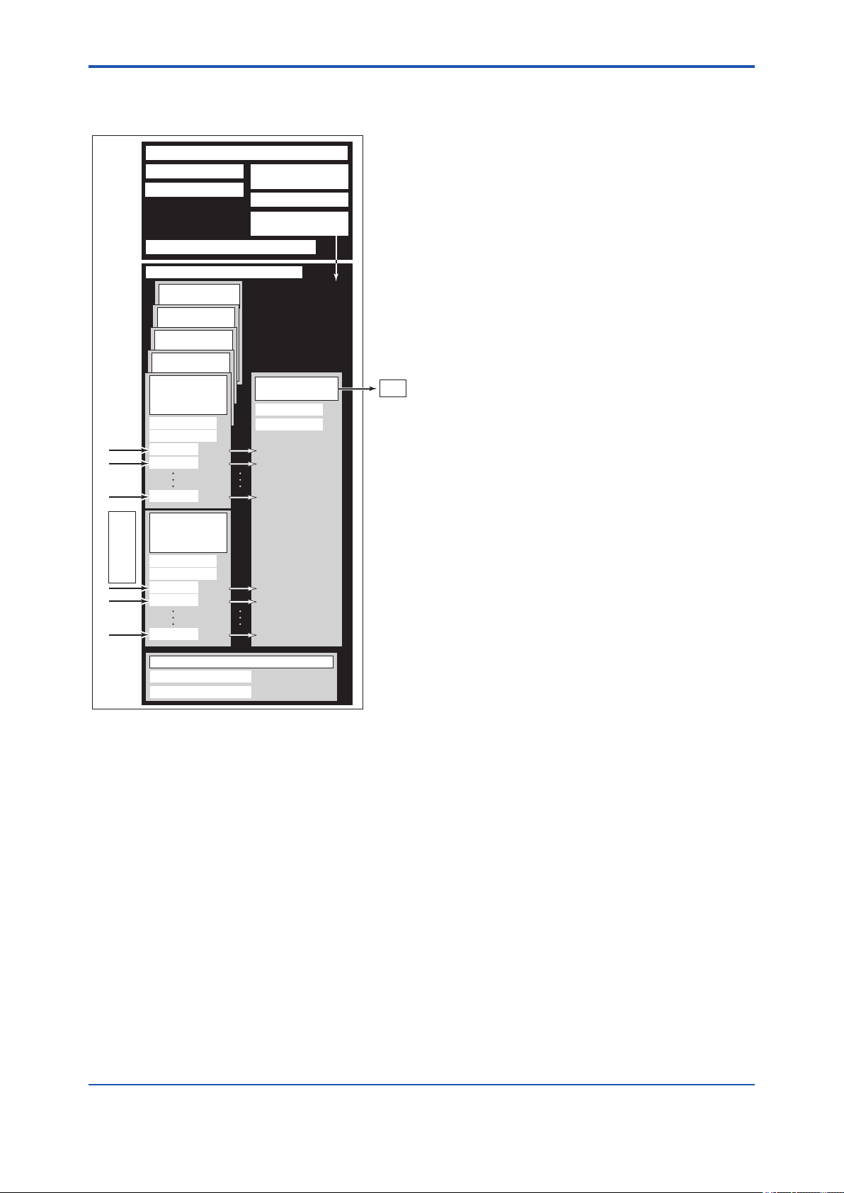
<4. About Fieldbus>
4-2
4.3 Logical Structure of Each Block
FVX110
System/network management VFD
PD Tag
Node address
Function block VFD
PID Function
block (x2)
AR F unct ion
bloc k (x 2)
IT Function
block
SC Function
block
MAO or IS
Function block
Block tag
Parameters
IN_1
IN_2
IN_8
MAO or IS
Function block
Link Master
Communication
parameters
VCR
Function block
execution schedule
LCD Transducer
block
Block tag
Parameters
4.4 Wiring System Conguration
The number of devices that can be connected to
a single bus and the cable length vary depending
on system design. When constructing systems,
both the basic and overall design must be carefully
considered to achieve optimal performance.
LCD
External input
Block tag
(Max. 16 input)
Parameters
IN_1
IN_2
IN_8
Block tag
Parameters
Resource block
F0401.ai
Figure 4.1 Logical Structure of Each Block
Setting of various parameters, node addresses,
and PD Tags shown in Figure 3.1 is required before
starting operation.
IM 01S01C01-01EN
Page 28
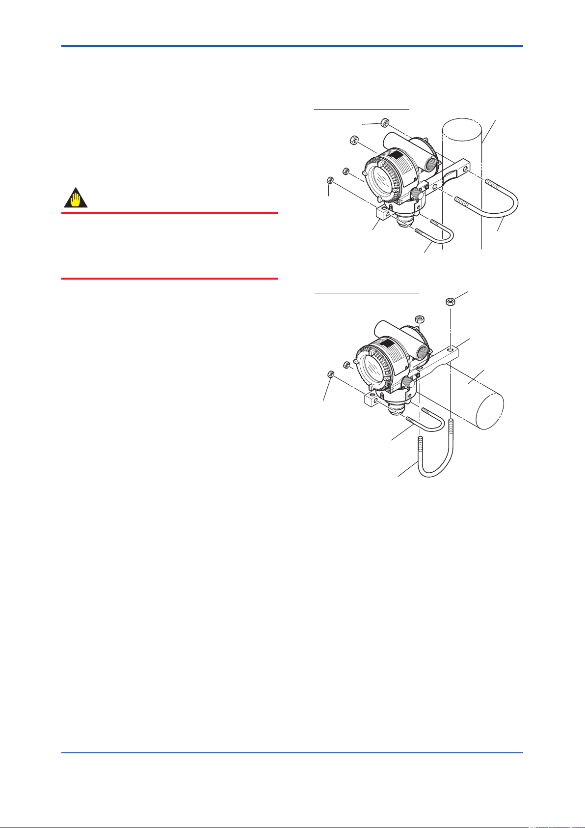
<5. Installation>
5. Installation
5-1
5.1 Precautions
Before installing the indicator, read the cautionary
notes in section 2.4, “Selecting the Installation
Location.” For additional information on the ambient
conditions allowed at the installation location, refer
to section 13.1 “Functional Specications.”
IMPORTANT
• When welding piping during construction,
take care not to allow welding currents to
ow through the indicator.
• Do not step on this instrument after
installation.
5.2 Mounting
■ The Indicator can be mounted on a nominal 50
mm (2-inch) pipe using the mounting bracket
supplied, as shown in Figure 5.1.
Vertical pipe mounting
U-bolt nut (L)
U-bolt nut (S)
Mounting bracket
U-bolt (S)
Horizontal pipe mounting
50 mm (2-inch) pipe
U-bolt (L)
U-bolt nut (L)
Mounting bracket
50 mm (2-inch) pipe
U-bolt nut (S)
U-bolt (S)
U-bolt (L)
Figure 5.1 Indicator Mounting
F0501.ai
IM 01S01C01-01EN
Page 29
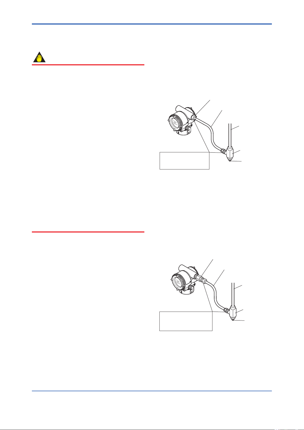
<5. Installation>
5-2
5.3 Wiring
5.3.1 Wiring Precautions
IMPORTANT
• Lay wiring as far as possible from electrical
noise sources such as large capacity
transformers, motors, and power supplies.
• Remove the electrical connection dust cap
before wiring.
• All threaded parts must be treated with
waterproong sealant. (A non-hardening
silicone group sealant is recommended.)
• To prevent noise pickup, do not pass signal
and power cables through the same ducts.
• Explosion-protected instruments must
be wired in accordance with specic
requirements (and, in certain countries,
legal regulations) in order to preserve the
effectiveness of their explosion-protected
features.
• The terminal box cover is locked by an
Allen head bolt (a shrouding bolt) on ATEX
ameproof type indicators. When the
shrouding bolt is driven clockwise using
an Allen wrench, it goes in. The cover lock
can then be released and the cover can
be opened by hand. See subsection 10.2
“Disassembly and Reassembly” for details.
• Plug and seal an unused conduit connection.
5.3.2 Wiring Installation
(1) General-use Type and Intrinsically Safe
Type
With the cable wiring, use a metallic conduit or
waterproof glands.
• Apply a non-hardening sealant to the terminal
box connection port and to the threads on the
exible metal conduit for waterproong.
Flameproof packing adapter
Flexible metal conduit
Wiring metal
conduit
Tee
Apply a non-hardening
sealant to the threads for
waterproofing.
Figure 5.2 Typical Wiring Using Flexible Metal
Conduit
(2) Flameproof Type
Wire cables through a ameproof packing adapter,
or use a ameproof metal conduit.
■ Wiring cable through ameproof packing
adapter.
• Apply a non-hardening sealant to the terminal
box connection port and to the threads on the
ameproof packing adapter for waterproong.
Drain plug
F0502.ai
Flameproof packing adapter
Flexible metal conduit
Wiring metal
conduit
Tee
Apply a non-hardening
sealant to the threads for
waterproofing.
Figure 5.3 Typical Cable Wiring Using Flameproof
Packing Adapter
Drain plug
F0503.ai
IM 01S01C01-01EN
Page 30
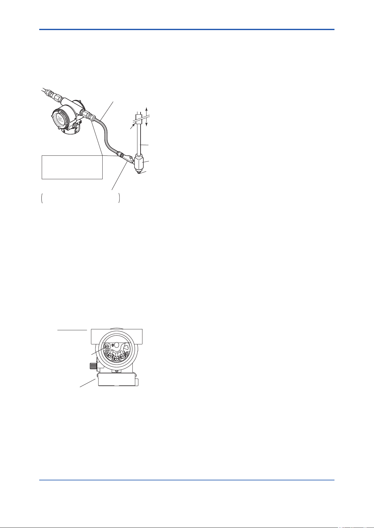
<5. Installation>
5-3
■ Flameproof metal conduit wiring
• A seal tting must be installed near the terminal
box connection port for a sealed construction.
• Apply a non-hardening sealant to the threads of
the terminal box connection port, exible metal
conduit and seal tting for waterproong.
Flameproof flexible
metal conduit
Gas sealing
device
Apply a non-hardening
sealant to the threads of
these fittings for
waterproofing
Seal fitting
After wiring, impregnate the fitting
with a compound to seal tubing.
Figure 5.4 Typical Wiring Using Flameproof Metal
Conduit
Non-hazardous
area
Hazardous area
Flameproof
heavy-gauge
steel conduit
Tee
Drain plug
F0504.ai
5.4 Grounding
Grounding is always required for the proper
operation of indicator. Follow the domestic electrical
requirements as regulated in each country. For a
indicator with a built-in lightning protector, grounding
should satisfy ground resistance of 10Ω or less.
Ground terminals are located on the inside and
outside of the terminal box. Either of these terminals
may be used.
Terminal box
PULSE
SUPPLY
CHECK
Ground terminal
(inside)
ALARM
5.5 Connection of Devices
The following are required for use with Fieldbus
devices:
• Power supply:
Fieldbus requires a dedicated power supply. It
is recommended that current capacity be well
over the total value of the maximum current
consumed by all devices (including the host).
Conventional DC current cannot be used as is.
• Terminator:
Fieldbus requires two terminators. Refer to
the supplier for details of terminators that are
attached to the host.
• Field devices:
Connect Fieldbus communication type eld
devices. Two or more EJX, YTA, AXF or other
devices can be connected.
• Host:
Used for accessing eld devices. A
dedicated host (such as DCS) is used for
an instrumentation line while dedicated
communication tools are used for experimental
purposes. For operation of the host, refer to
the instruction manual for each host. No other
details on the host are given in this manual.
• Cable:
Used for connecting devices. Refer to “Fieldbus
Technical Information” (TI 38K03A01-01E)
for details of instrumentation cabling. For
laboratory or other experimental use, a twisted
pair cable two to three meters in length with a
cross section of 0.9 mm2 or more and a cycle
period of within 5 cm (2 inches) may be used.
Termination processing depends on the type
of device being deployed. For FVX110, use an
M4 screw terminal claw. Some hosts require a
connector.
Ground terminal
(outside)
Figure 5.5 Ground Terminals
F0505.ai
Refer to Yokogawa when making arrangements to
purchase the recommended equipment.
Connect the devices as shown in Figure 5.6.
Connect the terminators at both ends of the
trunk, with a minimum length of the spur laid for
connection.
The polarity of signal and power must be
maintained.
IM 01S01C01-01EN
Page 31

<5. Installation>
5-4
Fieldbus power
supply
Terminator
Figure 5.6 Cabling
Communication
terminals
connection hook
SUPPLY +
SUPPLY –
SUPPLY
Figure 5.7 Wiring Diagram
+
Power supply and output terminal
–
Ground terminal
Field device
FVX110
HOST
Terminator
F0506.ai
F0507.ai
NOTE
No CHECK terminal is used for FVX110. Do not
connect anything on CHECK terminal.
Before using a Fieldbus conguration tool other
than the existing host, conrm it does not affect the
loop functionality in which all devices are already
installed in operation. Disconnect the relevant
control loop from the bus if necessary.
IMPORTANT
Connecting a Fieldbus conguration tool
to a loop with its existing host may cause
communication data scrambling resulting in a
functional disorder or a system failure.
5.6 Host Setting
To activate Fieldbus, the following settings are
required for the host.
IMPORTANT
Do not turn off the power immediately after
setting. When the parameters are saved to the
EEPROM, the redundant processing is executed
for an improvement of reliability. If the power
is turned off within 60 seconds after setting is
made, the modied parameters are not saved
and the settings may return to the original values.
Table 5.1 Operation Parameters
Symbol Parameter Description and Settings
V (ST) Slot-Time Indicates the time
V (MID) Minimum-Inter-
PDU-Delay
V (MRD) Maximum-
Reply-Delay
V (FUN) First-Unpolled-
Node
V (NUN) Number-of-
consecutiveUnpolled-Node
necessary for immediate
reply of the device. Unit of
time is in octets (256 μs).
Set maximum
specication for all
devices. For FVX110, set
a value of 4 or greater.
Minimum value of
communication data
intervals. Unit of time is in
octets (256 μs). Set the
maximum specication for
all devices. For FVX110,
set a value of 4 or greater.
The worst case time
elapsed until a reply is
recorded. The unit is
Slot-time; set the value
so that V (MRD) × V (ST)
is the maximum value of
the specication for all
devices. For FVX110, the
setting must be a value of
12 or greater.
Indicate the address next
to the address range used
by the host. Set 0 × 15 or
greater.
Unused address range.
IM 01S01C01-01EN
Page 32

<5. Installation>
0x00
Not used
0x0F
V(FUN)
V(FUN)+V(NUN)
0x10
0x13
0x14
0xF7
0xF8
Bridge device
LM device
Unused V(NUN)
BASIC device
Device ID : 5945430010XXXXXXXX
PD Tag : UT1001
Device Revision : 3
Node Address : 0xf3
Serial No. : XXXXXXXXXXXXXXXXX
Physical Location :
Note:
Our Device Description Files and Capabilities Files available at
http://www.yokogawa.com/fld (English) or
http://www.yokogawa.co.jp/Sensor/fieldbus/fieldbus.htm (Japanese)
DEVICE INFORMATION
Default address
0xFB
0xFC
Portable device address
0xFF
Note 1: Bridge device: A linking device which brings data
from one or more H1 networks.
Note 2: LM device: with bus control function (Link Master
function).
Note 3: BASIC device: without bus control function.
F0508.ai
Device ID : 5945430010XXXXXXXX
PD Tag : UT1001
Device Revision : 3
Node Address : 0xf3
Serial No. : XXXXXXXXXXXXXXXXX
Physical Location :
Note:
Our Device Description Files and Capabilities Files available at
http://www.yokogawa.com/fld (English) or
http://www.yokogawa.co.jp/Sensor/fieldbus/fieldbus.htm (Japanese)
DEVICE INFORMATION
Figure 5.8 Available Address Range
5-5
5.7 Bus Power ON
Turn on the power of the host and the bus. After
displaying the startup screen shown in Figure 5.9,
the regular screen display appears. If the indicator
is not lit, check the polarity of the power supply.
F0509.ai
Figure 5.9
Using the host device display function, check that
the FVX110 is in operation on the bus.
The device information, including PD tag, Node
address, and Device ID, is described on the sheet
attached to the FVX110. The device information is
given in duplicate on this sheet.
F0510.ai
Figure 5.10 Device Information Sheet Attached to
FVX110
If no FVX110 is detected, check the available
address range and the polarity of the power supply.
If the node address and PD tag are not specied
when ordering, default value is factory set. If two
or more FVX110s are connected at a time with
default value, only one FVX110 will be detected
from the host as FVX110 have the same initial
address. Separately connect each FVX110 and set
a different address for each.
IM 01S01C01-01EN
Page 33

<5. Installation>
5-6
5.8 Integration of DD
If the host supports DD (Device Description), the
DD of the FVX110 needs to be installed. Check if
host has the following directory under its default DD
directory.
594543\0010
(594543 is the manufacturer number of
Yokogawa Electric Corporation, and 0010 is the
FVX110 device number, respectively.)
If this directory is not found, the DD of the FVX110
has not been included. Create the above directory
and copy the DD le (0m0n.ffo, 0m0n.sym) (m, n is
a numeral) into the directory. ‘0m’ in the le name
shows the device revision, and ‘0n’ shows the DD
revision. If you do not have the DD or capabilities
les, you can download them from our web site:
http://www.yokogawa.com/d
Once the DD is installed in the directory, the name
and attribute of all parameters of the FVX110 are
displayed.
5.10 Continuous Record of Values
If the host has a function that continuously
records the indications, use this function to list the
indications (values). Depending on the host being
used, it may be necessary to set the schedule of
Publish (the function that transmits the indication on
a periodic basis).
5.11 Generation of Alarm
Generation of an alarm can be attempted from
FVX110. Block alarm, Output limit alarm, and
Update alarm are informed to the host. When
generating alarm, a Link Object and a VCR Static
Entry need to be set. For details of Link Object and
VCR Static Entry, refer to section 6.6.1 Link object
and section 6.5.1 VCR Setting.
Off-line conguration is possible by using
capabilities les.
5.9 Set the Parameters Using DTM
Following Device DTM on YOKOGAWA FieldMate
can be used to congure the parameters for
FVX110 Fieldbus Segment Indicator
Table 5.2 YOKOGAWA device DTM for FVX110
Fieldbus Segment Indicator
Device
DTM
Name
FVX FF
DTM
FVX110 Fieldbus Segment Indicator
Model
Name
FVX110
Device
Type
FVX
(0x0010)
Device
Revision
1
NOTE
For more information on FieldMate, refer to
the User’s Manual IM 01R01A01-1E “Versatile
Device Management Wizard”.
IM 01S01C01-01EN
Page 34

<6. Conguration>
6. Conguration
6-1
This chapter describes how to adapt the function
and performance of the FVX110 to suit specic
applications. Because multiple devices are
connected to Fieldbus, it is important to carefully
consider the device requirements and settings
when conguring the system. The following steps
must be taken.
(1) Network design
Determines the devices to be connected to
Fieldbus and checks the capacity of the power
supply.
(2) Network denition
Determines the tag and node addresses for all
devices.
(3) Denition of combining function blocks
Determines how function blocks are combined.
(4) Setting tags and addresses
Sets the PD Tag and node addresses for each
device.
(5) Communication setting
Sets the link between communication
parameters and function blocks.
(6) Block setting
Sets the parameters for function blocks.
The following section describes in sequence each
step of this procedure. The use of a dedicated
conguration tool signicantly simplies this
procedure. Refer to Appendix 7 when the FVX110 is
used as Link Master.
6.1 Network Design
Select the devices to be connected to the Fieldbus
network. The following are essential for the
operation of Fieldbus.
• Power supply
Fieldbus requires a dedicated power supply. It
is recommended that current capacity be well
over the total value of the maximum current
consumed by all devices (including the host).
Conventional DC current cannot be used as
this.
• Terminator
Fieldbus requires two terminators. Refer to
the supplier for details of terminators that are
attached to the host.
• Field devices
Connect the eld devices necessary for
instrumentation. The FVX110 has passed the
interoperability test conducted by The Fieldbus
Foundation. In order to properly start Fieldbus,
it is recommended that the devices used satisfy
the requirements of the above test.
• Host
Used for accessing eld devices. A minimum
of one device with the bus control function is
needed.
• Cable
Used for connecting devices. Refer to
“Fieldbus Technical Information” for details
of instrumentation cabling. Provide a cable
sufciently long to connect all devices. For
eld branch cabling, use terminal boards or a
connection box as required.
First, check the capacity of the power supply. The
power supply capacity must be greater than the
sum of the maximum current consumed by all
devices to be connected to Fieldbus. The maximum
current consumed (power supply voltage 9 V to
32 V) for the FVX110 is 15 mA (24 mA in Software
download operation). The cable used for the spur
must be of the minimum possible length.
IM 01S01C01-01EN
Page 35

<6. Conguration>
6-2
6.2 Network Denition
Before connection of devices with Fieldbus, dene
the Fieldbus network. Allocate PD Tag and node
addresses to all devices (excluding such passive
devices as terminators).
The PD Tag is the same as the conventional
one used for the device. Up to 32 alphanumeric
characters may be used for denition. Use a
hyphen as a delimiter as required.
The node address is used to specify devices for
communication purposes. Because this data is
too long for a PD Tag, the host uses the node
address in place of the PD Tag for communication.
A range of 20 to 247 (or hexadecimal 14 to F7) can
be set. The device (LM device) with bus control
function (Link Master function) is allocated from
a smaller address number (20) side, and other
devices (BASIC device) without bus control function
allocated from a larger address number (247) side
respectively. Place the FVX110 in the range of the
BASIC device. When the FVX110 is used as Link
Master, place the FVX110 in the range of the LM
device. Set the range of addresses to be used to
the LM device. Set the following parameters.
Table 6.1 Parameters for Setting Address Range
Symbol Parameters Description
V (FUN) First-Unpolled-
Node
V (NUN) Number-of-
consecutiveUnpolled-Node
The devices within the address range written
as “Unused” in Figure 6.1 cannot be used on a
Fieldbus. For other address ranges, the range is
periodically checked to identify when a new device
is mounted. Care must be taken to keep the unused
device range as narrow as possible so as to lessen
the load on the Fieldbus.
Indicates the address
next to the address range
used for the host or other
LM device.
Unused address range
0x00
Not used
0x0F
0x10
0x13
0x14
V(FUN)
V(FUN)+V(NUN)
0xF7
0xF8
0xFB
0xFC
0xFF
Figure 6.1 Available Range of Node Addresses
Bridge device
LM device
Unused V(NUN)
BASIC device
Default address
Portable device address
F0601.ai
To ensure stable operation of Fieldbus, determine
the operation parameters and set them to the LM
devices. While the parameters in Table 6.2 are to
be set, the worst-case value of all the devices to
be connected to the same Fieldbus must be used.
Refer to the specication of each device for details.
Table 6.2 lists FVX110 specication values.
Table 6.2 Operation Parameter Values of the
FVX110 to be Set to LM Devices
Symbol Parameters
V (ST) Slot-Time Indicates the time
V (MID) Minimum-Inter-
PDU-Delay
V (MRD) Maximum-
Reply-Delay
Description and
Settings
necessary for immediate
reply of the device. Unit of
time is in octets (256 μs).
Set maximum
specication for all
devices. For FVX110, set
a value of 4 or greater.
Minimum value of
communication data
intervals. Unit of time is in
octets (256 μs). Set the
maximum specication
for all devices. For
FVX110, set a value of 4
or greater.
The worst case time
elapsed until a reply is
recorded. The unit is
Slottime; set the value
so that V (MRD) × V (ST)
is the maximum value of
the specication for all
devices. For FVX110, the
setting must be a value
of 12 or, greater and
V (MID) < V (MRD) × V
(ST).
IM 01S01C01-01EN
Page 36

<6. Conguration>
6.3 Denition of Combining
Function Blocks
The input/output parameters for function blocks are
combined. As required, they can be combined with
the input of the control block. The setting is written
to the FVX110 link object. See “Block setting” in
Section 6.6 for the details. It is also possible to read
values from the host at proper intervals instead
of connecting the FVX110 block output to other
blocks.
EJX
#1
LI100
LIC100
FVX
110
FIC100
6-3
UI100
The combined blocks need to be executed
synchronously with other blocks on the
communications schedule. In this case, change the
FVX110 schedule according to the following table.
The values in the table are factory-settings.
Table 6.3 Execution Schedule of the FVX110
Function Blocks
Index Parameters
269
MACROCYCLE_
(SM)
DURATION
Setting (Enclosed is
factory-setting)
Cycle
(MACROCYCLE)
period of control or
measurement. Unit
is 1/32 ms. (32000 =
1.0 s)
276
FB_START_ENTRY.1 Excution block startup
(SM)
time.
Elapsed time from the
start of MACROCYCLE
specied in 1/32 ms.
(0 = 0 s)
277
FB_START_ENTRY.2
to
to
291
FB_START_ENTRY.16
(SM)
Excution block startup
time.
Elapsed time from the
start of MACROCYCLE
specied in 1/32 ms.
(0 = 0 s)
A maximum of 30 ms is taken for execution of MAO
function block and IS function block. For scheduling
of communications for combination with the next
function block, the execution is so arranged as to
start after a lapse of longer than 30 ms. In no case
should function blocks of the FVX110 be executed
at the same time (execution time is overlapped).
Figure 6.3 shows an example of schedule based on
the loop shown in Figure 6.2.
EJX
#2
FI100
FC100
F0602.ai
Figure 6.2 Example of Loop Connecting Function
Block of FVX110 and Two EJX with
Other Instruments
Macrocycle (Control Period)
LI100
OUT
Commu-
nication
Schedule
OUT
LIC100
BKCAL_IN
FI100
IN
OUT
CAS_IN
BKCAL_OUT
FIC100
IN
OUT
BKCAL_IN
Unscheduled Communication
Scheduled Communication
FC100
BKCAL_OUT
IN_1
UI 100
IN_2
F0603.ai
Figure 6.3 Function Block Schedule and
Communication Schedule
When the control period (macrocycle) is set to more
than 4 seconds, set the following intervals to be
more than 1% of the control period.
- Interval between “end of block execution” and
“start of sending CD from LAS”
- Interval between “end of block execution” and
“start of the next block execution”
IM 01S01C01-01EN
Page 37

<6. Conguration>
6-4
6.4 Setting of Tags and Addresses
This section describes the steps in the procedure
to set PD Tags and node addresses in the FVX110.
There are three states of Fieldbus devices as
shown in Figure 6.4, and if the state is other than
the lowest SM_OPERATIONAL state, no function
block is executed. FVX110 must be transferred
to this state when an FVX110 tag or address is
changed.
UNINITIALIZED
(No tag nor address is set)
Tag clear Tag setting
INITIALIZED
(Only tag is set)
Address clear
SM_OPERATIONAL
(Tag and address are retained, and
the function block can be executed.)
Figure 6.4 Status Transition by Setting PD Tag and
Node Address
FVX110 has a PD Tag (UT1001) and node
address (245, or hexadecimal F5) that are set
upon shipment from the factory unless otherwise
specied. To change only the node address, clear
the address once and then set a new node address.
To set the PD Tag, rst clear the node address and
clear the PD Tag, then set the PD Tag and node
address again.
Devices whose node addresses have been cleared
will have the default address (randomly chosen
from a range of 248 to 251, or from hexadecimal
F8 to FB). At the same time, it is necessary to
specify the device ID in order to correctly specify
the device. The device ID of the FVX110 is
5945430010xxxxxxxx. (The xxxxxxxx at the end
of the above device ID is a total of 8 alphanumeric
characters.)
Address setting
F0604.ai
6.5 Communication Setting
To set the communication function, it is necessary
to change the database residing in SM-VFD.
6.5.1 VCR Setting
Set VCR (Virtual Communication Relationship),
which species the called party for communication
and resources. FVX110 has 35 VCRs whose
application can be changed, except for the rst
VCR, which is used for management.
FVX110 has VCRs of four types:
Server(QUB) VCR
A Server responds to requests from a host. This
communication needs data exchange. This
type of communication is called QUB (Queued
User-triggered Bidirectional) VCR.
Source (QUU) VCR
A Source multicasts alarms or trends to other
devices. This type of communication is called
QUU (Queued User-triggered Unidirectional)
VCR.
Publisher (BNU) VCR
A Publisher multicasts AI block output of eld
device to another function block(s). This type
of communication is called BNU (Buffered
Network-triggered Unidirectional) VCR.
Subscriber (BNU) VCR
A Subscriber receives output of another
function block(s) by MAO block or PID block.
A Server VCR is capable to responding to
requests from a Client (QUB) VCR after the Client
successfully initiates connection to the Server. A
Source VCR transmits data without established
connection. A Sink (QUU) VCR on another device
can receive it if the Sink is congured so. A
Publisher VCR transmits data when LAS requests
so. An explicit connection is established from
Subscriber (BNU) VCR(s) so that a Subscriber
knows the format of published data.
Each VCR has the parameters listed in Table 6.4.
Parameters must be changed together for each
VCR because modication of individual parameters
may cause inconsistent operation.
IM 01S01C01-01EN
Page 38

<6. Conguration>
Table 6.4 VCR Static Entry
Sub-
index
Parameter Description
1 FasArTypeAndRole Indicates the type and
role of communication
(VCR). The following
4 types are used for
FVX110.
0x32: Server
(Responds to
requests from
host.)
0x44: Source
(Transmits alarm
or trend.)
0x66: Publisher (Sends
AI block output
of eld device to
other blocks.)
0x76: Subscriber
(Receives output
of other blocks by
MAO block or PID
block.)
2 FasDllLocalAddr Sets the local address
to specify VCR in
FVX110. A range of 20
to F7 in hexadecimal.
3 FasDllCongured
RemoteAddr
Sets the node address
of the called party for
communication and
Sub-
index
Parameter Description
7 FasDllMaxDlsduSize Species maximum DL
Service Data unit Size
(DLSDU). Set 256 for
Server and Trend VCR,
and 64 for other VCRs.
8 FasDllResidual
ActivitySupported
Species whether
connection is
monitored. Set TRUE
(0xff) for Server.
This parameter is
not used for other
communication.
9 FasDllTimelinessClass Not used for FVX110.
10 FasDllPublisherTime
Not used for FVX110.
WindowSize
11 FasDllPublisher
Not used for FVX110.
SynchronizaingDlcep
12 FasDllSubsriberTime
Not used for FVX110.
WindowSize
13 FasDllSubscriber
Not used for FVX110.
SynchronizationDlcep
14 FmsVfdId Sets VFD for FVX110
to be used.
0x1: System/network
0x1234: Function block
the address (DLSAP
or DLCEP) used to
specify VCR in that
address. For DLSAP or
DLCEP, a range of 20
to F7 in hexadecimal is
used.
Addresses in Subindex
2 and 3 need to be set
to the same contents of
the VCR as the called
party (local and remote
are reversed).
4 FasDllSDAP Species the quality
of communication.
15 FmsMaxOutstanding
ServiceCalling
16 FmsMaxOutstanding
ServiceCalled
17 FmsFeatures
Supported
Set 0 to Server. It is
not used for other
applications.
Set 1 to Server. It is
not used for other
applications.
Indicates the type
of services in the
application layer.
In the FVX110, it is
automatically set
according to specic
applications.
Usually, one of the
following types is set.
35 VCRs are factory-set as shown in the Table 6.5.
0x2B: Server
0x01: Source (Alert)
0x03: Source (Trend)
0x91: Publisher/
Subscriber
5 FasDllMaxConrm
DelayOnConnect
To establish connection
for communication, a
maximum wait time
for the called party's
response is set in ms.
Typical value is 60
secounds (60000).
6 FasDllMaxConrm
DelayOnData
For request of data,
a maximum wait time
for the called party's
response is set in ms.
Typical value is 60
secounds (60000).
6-5
management VFD
VFD
IM 01S01C01-01EN
Page 39

<6. Conguration>
6-6
Table 6.5 VCR List
Index
(SM)
303 1 For system management (Fixed)
304 2 Server (LocalAddr = 0xF3)
305 3 Server (LocalAddr = 0xF4)
306 4 Server (LocalAddr = 0xF7)
307 5 Trend Source (LocalAddr = 0x07,
308 6 Publisher for PID1 (LocalAddr =
309 7 Alert Source (LocalAddr = 0x07,
310 8 Server (LocalAddr = 0xF9)
311 9 Publisher for PID2 (LocalAddr =
312 to
337
VCR
Number
Remote Address=0x111)
0x20)
Remote Address=0x110)
0x21)
10 to 35 Not used.
Factory Setting
6.5.2 Function Block Execution Control
According to the instructions given in Section 6.3,
set the execution cycle of the function blocks and
schedule of execution.
6.6 Block Setting
Table 6.6 Link Object Parameters
Sub-
index
1 LocalIndex Sets the index of function
2 VcrNumber Sets the index of VCR to be
3 RemoteIndex Not used in FVX110. Set
4 ServiceOperation Set one of the following.
5 StaleCountLimit Set the maximum number
Parameter Description
block parameters to be
combined; set “0” for Trend
and Alert.
combined. If set to “0”, this
link object is not used.
to “0”.
Set only one each for link
object for Alert or Trend.
0: Undened
2: Publisher
3: Subscriber
6: Alert
7: Trend
of consecutive stale input
values which may be
received before the input
status is set to BAD. To
avoid the unnecessary
mode transition caused
when the data is not
correctly received by
subscriber, set this
parameter to “2” or more.
Set the parameter for function block VFD.
6.6.1 Link Object
A link object combines the data voluntarily sent by
the function block with the VCR. The FVX110 has
40 link objects. A single link object species one
combination. Each link object has the parameters
listed in Table 6.6. Parameters must be changed
together for each VCR because the modications
made to each parameter may cause inconsistent
operation.
IM 01S01C01-01EN
Page 40

<6. Conguration>
6-7
6.6.2 Trend Object
It is possible to set the parameter so that the
function block automatically transmits Trend.
FVX110 has seven Trend objects, six of which are
used for Trend in analog mode parameters and
one is used for Trend in discrete mode parameter.
A single Trend object species the trend of one
parameter.
Each Trend object has the parameters listed in
Table 6.8. The rst four parameters are the items
to be set. Before writing to a Trend object, it is
necessary to release the WRITE_LOCK parameter.
Table 6.7 Parameters for Trend Objects
Sub-
index
1 Block Index Sets the leading index
2 Parameter Relative
3 Sample Type Species how trends are
4 Sample Interval Species sampling
5 Last Update The last sampling time.
6 to 21List of Status Status part of a sampled
21 to 37List of Samples Data part of a sampled
Parameter Description
of the function block that
takes a trend.
Index
Sets the index of
parameters taking a trend
by a value relative to the
beginning of the function
block.
taken. Choose one of the
following 2 types:
1: Sampled upon
execution of a function
block.
2: The average value is
sampled.
intervals in units of 1/32
ms. Set the integer
multiple of the function
block execution cycle.
parameter.
parameter.
6.6.3 View Object
This object forms a group of parameters in a
block. One advantage brought by forming groups
of parameters is the reduction of load for data
transactions. View Object has the parameters listed
in Table 6.10 and 6.11. Purpose of View Objects is
shown in Table 6.9.
Table 6.9 Purpose of Each View Object
Description
VIEW_1 Set of dynamic parameters required by
operator for plant operation. (PV, SP, OUT,
Mode etc.)
VIEW_2 Set of static parameters which need to be
shown to plant operator at once. (Range etc.)
VIEW_3 Set of all the dynamic parameters.
VIEW_4 Set of static parameters for conguration or
maintenance.
Seven trend objects are factory-set as shown Table
6.8.
Table 6.8 Trend Object are Factory-Set
Index Parameters Factory Settings
32000 to
32005
32006 TREND_DIS.1 Not used.
TREND_FLT.1 to
TREND_FLT.5
Not used.
IM 01S01C01-01EN
Page 41

<6. Conguration>
Table 6.10 View Object for Resource Block
Relative
Index
1 ST_REV 2 2 2 2 2
2 TAG_DESC
3 STRATEGY 2
4 ALERT_KEY 1
5 MODE_BLK 4 4
6 BLOCK_ERR 2 2
7 RS_STATE 1 1
8 TEST_RW
9 DD_RESOURCE
10 MANUFAC_ID 4
11 DEV_TYPE 2
12 DEV_REV 1
13 DD_REV 1
14 GRANT_DENY 2
15 HARD_TYPES 2
16 RESTART
17 FEATURES 2
18 FEATURE_SEL 2
19 CYCLE_TYPE 2
20 CYCLE_SEL 2
21 MIN_CYCLE_T 4
22 MEMORY_SIZE 2
23 NV_CYCLE_T 4
24 FREE_SPACE 4
25 FREE_TIME 4 4
26 SHED_RCAS 4
27 SHED_ROUT 4
28 FAULT_STATE 1 1
29 SET_FSTATE
30 CLR_FSTATE
31 MAX_NOTIFY 1
32 LIM_NOTIFY 1
33 CONFIRM_TIME 4
34 WRITE_LOCK 1
35 UPDATE_EVT
36 BLOCK_ALM
37 ALARM_SUM 8 8
38 ACK_OPTION 2
39 WRITE_PRI 1
40 WRITE_ALM
41 ITK_VER 2
42 SOFT_REV
43 SOFT_DESC
44 SIM_ENABLE_MSG
45 DEVICE_STATUS_1 4
46 DEVICE_STATUS_2 4
47 DEVICE_STATUS_3 4
48 DEVICE_STATUS_4 4
49 DEVICE_STATUS_5 4
50 DEVICE_STATUS_6 4
51 DEVICE_STATUS_7 4
52 DEVICE_STATUS_8 4
53 SOFTDWN_PROTECT 1
54 SOFTDWN_FORMAT 1
55 SOFTDWN_COUNT 2
56 SOFTDWN_ACT_AREA 1
57 SOFTDWN_MOD_REV 16
58 SOFTDWN_ERROR 2
59 SOFTDWN_HISTORY
60 SOFTDWN_HIST_INDEX
61 COMPATIBILITY_REV 1
62 CAPABILITY_LEV 1
63 CAPABILITY_CONFIG 2
64 WRITE_LOCK_LEVEL 1
65 SI_CONTROL_CODES 1
66 FD_VER 2
Parameter Mnemonic
1 2
View
3_1 3_2 4_1 4_2
Relative
Index
67 FD_FAIL_ACTIVE 4 4
68 FD_OFFSPEC_ACTIVE 4 4
69 FD_MAINT_ACTIVE 4 4
70 FD_CHECK_ACTIVE 4 4
71 FD_FAIL_MAP 4
72 FD_OFFSPEC_MAP 4
73 FD_MAINT_MAP 4
74 FD_CHECK_MAP 4
75 FD_FAIL_MASK 4
76 FD_OFFSPEC_MASK 4
77 FD_MAINT_MASK 4
78 FD_CHECK_MASK 4
79 FD_FAIL_ALM
80 FD_OFFSPEC_ALM
81 FD_MAINT_ALM
82 FD_CHECK_ALM
83 FD_FAIL_PRI 1
84 FD_OFFSPEC_PRI 1
85 FD_MAINT_PRI 1
86 FD_CHECK_PRI 1
87 FD_SIMULATE 9
88 FD_RECOMMEN_ACT 2 2
89 FD_EXTENDED_ACTIVE_1 4
90 FD_EXTENDED_ACTIVE_2 4
91 FD_EXTENDED_ACTIVE_3 4
92 FD_EXTENDED_ACTIVE_4 4
93 FD_EXTENDED_ACTIVE_5 4
94 FD_EXTENDED_ACTIVE_6 4
95 FD_EXTENDED_ACTIVE_7 4
96 FD_EXTENDED_ACTIVE_8 4
97 FD_EXTENDED_MAP_1 4
98 FD_EXTENDED_MAP_2 4
99 FD_EXTENDED_MAP_3 4
100 FD_EXTENDED_MAP_4 4
101 FD_EXTENDED_MAP_5 4
102 FD_EXTENDED_MAP_6 4
103 FD_EXTENDED_MAP_7 4
104 FD_EXTENDED_MAP_8 4
105 PRIVATE_1
106 PRIVATE_2
107 PRIVATE_3
108 PRIVATE_4
109
110 PRIVATE_6
111 PRIVATE_7
112 PRIVATE_8
113 PRIVATE_9
114 PRIVATE_10
115 PRIVATE_11
Parameter Mnemonic
PRIVATE_5
Total (# bytes) 40 32 77 61 73 32
1 2
6-8
View
3_1 3_2 4_1 4_2
IM 01S01C01-01EN
Page 42

<6. Conguration>
6-9
Table 6.11 View Object for LCD Transducer Block
Relative
Index
1
2
3
4
5
6
7
8
9
10
11
12
13
14
15
16
17
18
19
20
21
22
23
24
25
26
27
28
29
30
31
32
33
34
35
36
37
38
39
40
41
42
43
44
45
46
47
48
49
50
51
52
53
54
55
56
57
58
59
60
61
62
63
64
65
66
Parameter Mnemonic
ST_REV
TAG_DESC
STRATEGY
ALERT_KEY
MODE_BLK
BLOCK_ERR
UPDATE_EVT
BLOCK_ALM
TRANSDUCER_DIRECTORY
TRANSDUCER_TYPE
XD_ERROR
COLLECTION_DIRECTORY
NOW_DISPLAYING
DISP_TARGET_FORCE
NO_OF_VALID_CON
VALID_CON_SUMMARY
MAO_CON_SUMMARY
ISEL_CON_SUMMARY
SIM_CON_SUMMARY
BAR_GRAPH_SELECT
EACH_BAR_GRAPH
MAIN_TAG_SCROLL
V_SCROLL_BAR
SCROLL_DIRECTION
DISP_PAGE_INFO
DISP_QUIET_MODE
DISP_FORMAT_TYPE
DISPLAY_CYCLE
DISPLAY_TEST
DISPLAY_CONTRAST
SQUAWK
AMBIENT_TEMPERATURE
MAIN_CONNECT_TYPE
IN01_CONNECTION
IN02_CONNECTION
IN03_CONNECTION
IN04_CONNECTION
IN05_CONNECTION
IN06_CONNECTION
IN07_CONNECTION
IN08_CONNECTION
IN09_CONNECTION
IN10_CONNECTION
IN11_CONNECTION
IN12_CONNECTION
IN13_CONNECTION
IN14_CONNECTION
IN15_CONNECTION
IN16_CONNECTION
IN_01
IN_02
IN_03
IN_04
IN_05
IN_06
IN_07
IN_08
IN_09
IN_10
IN_11
IN_12
IN_13
IN_14
IN_15
IN_16
IN01_MAIN_TAG
View
1 2 3 4
2 2 2 2
4 4
2 2
2 2 2 2
1 1
1 1
1 1
1 1
2 2
2 2
2 2
2
1
4 4
1 1
1 1
1 1
1 1
1 1
1 1
1 1
1 1
1 1
1 1
1 1
1 1
1 1
1 1
1 1
1 1
5 5
5 5
5 5
5 5
5 5
5 5
5 5
5 5
5 5
5 5
5 5
5 5
5 5
5 5
5 5
5 5
Relative
Index
67
68
2
1
2
1
1
1
1
1
1
1
1
1
69
70
71
72
73
74
75
76
77
78
79
80
81
82
83
84
85
86
87
88
89
90
91
92
93
94
95
96
97
98
99
100
101
102
103
104
105
106
107
108
109
110
111
112
113
114
115
116
117
118
119
120
121
122
123
124
125
Parameter Mnemonic
IN01_SUB_TAG
IN01_SCALE
IN02_MAIN_TAG
IN02_SUB_TAG
IN02_SCALE
IN03_MAIN_TAG
IN03_SUB_TAG
IN03_SCALE
IN04_MAIN_TAG
IN04_SUB_TAG
IN04_SCALE
IN05_MAIN_TAG
IN05_SUB_TAG
IN05_SCALE
IN06_MAIN_TAG
IN06_SUB_TAG
IN06_SCALE
IN07_MAIN_TAG
IN07_SUB_TAG
IN07_SCALE
IN08_MAIN_TAG
IN08_SUB_TAG
IN08_SCALE
IN09_MAIN_TAG
IN09_SUB_TAG
IN09_SCALE
IN10_MAIN_TAG
IN10_SUB_TAG
IN10_SCALE
IN11_MAIN_TAG
IN11_SUB_TAG
IN11_SCALE
IN12_MAIN_TAG
IN12_SUB_TAG
IN12_SCALE
IN13_MAIN_TAG
IN13_SUB_TAG
IN13_SCALE
IN14_MAIN_TAG
IN14_SUB_TAG
IN14_SCALE
IN15_MAIN_TAG
IN15_SUB_TAG
IN15_SCALE
IN16_MAIN_TAG
IN16_SUB_TAG
IN16_SCALE
MS_CODE
SERIAL_NO
MANUFAC_DATE
TEST_KEY1
TEST_KEY2
TEST_KEY3
TEST_1
TEST_2
TEST_3
TEST_4
TEST_5
TEST_6
Total (# bytes)
104 23 104 34
View
1 2 3 4
IM 01S01C01-01EN
Page 43

<6. Conguration>
Table 6.12 Indexes of View for Each Block
VIEW1VIEW2VIEW3VIEW
4
Resourse Block 40100 40101 40102 40103
LCD Transducer Block
PID1 Function Block 40800 40801 40802 40803
PID2 Function Block 40810 40811 40812 40813
MAO1 Function Block 41000 41001 41002 41003
MAO2 Function Block 41010 41011 41012 41013
SC Function Block 41450 41451 41452 41453
IT Function Block 41600 41601 41602 41603
IS1 Function Block 41700 41701 41702 41703
IS2 Function Block 41710 41711 41712 41713
AR1 Function Block 41750 41751 41752 41753
AR2 Function Block 41760 41761 41762 41763
40250 40251 40252 40253
6.6.4 Function Block Parameters
Function block parameters can be read from the
host or can be set. For a list of the parameters
of blocks refer to “12. Parameter Lists”. For the
function blocks, LM function and software download
function, refer to Appendix 1 to 8.
6-10
IM 01S01C01-01EN
Page 44

<7. Explanation of Basic Items>
7. Explanation of Basic Items
7-1
7.1 Outline
This chapter provides an outline of the LCD
transducer block and describes basic parameter
setup procedures. For information on function
blocks as well as the LM function and software
download functions, refer to Appendix 1 to 8.
7.2 Setting and Changing Parameters for the Whole Process
IMPORTANT
Do not turn off the power immediately after
making a setting. When data is saved to the
EEPROM, redundant processing is performed
to enhance reliability. If the power is turned off
within 60 seconds after making a setting, the
modied parameters are not saved and may
return to their original values.
Operating mode
Many parameters require a change of operating
mode of the function block to O/S (Out of Service)
to rewrite parameter data. To change the operating
mode of the function block, its MODE_BLK needs
to be changed. The MODE_BLK is comprised of
the four sub-parameters below:
(1) Target (target mode):
Parameter to set the operating mode of the
block.
(2) Actual (Actual mode):
Parameter to indicate the current operating
mode of the block.
(3) Permit (Permitted mode):
Parameter to indicate operating mode that the
block is allowed to take.
(4) Normal (Normal mode):
Parameter to indicate the operating mode the
block will usually take.
7.3 LCD Transducer Block
7.3.1 Function Outline
The LCD transducer block controls the indications
displayed on the LCD. FVX110 displays process
variables from eld instruments which have
received in MAO or IS function block and also
simulation input.
7.3.2 Operating mode
The operating conditions permitted for the LCD
transducer block are Automatic (AUTO) and Out
of Service (O/S) mode. Settings can normally
be changed in the O/S mode, but can also be
performed in the Auto mode except for changes of
the block tag parameter of the block header in the
LCD transducer block.
7.3.3 Indicator names and functions
The LCD consists of three elds: the top, center
and bottom elds. The top eld shows the Main
Tag which identies the instrument whose values
are indicated (for example PD_Tag), and other
freely settable information. It also shows the page
information (number of displayed page)/(total
number of display pages). The middle eld shows
process value and measuring unit. The lower
eld shows the Sub Tag, a eld indicating data
required for identifying instruments whose values
are displayed, communication status, bar graph
and other information. At the center right edge,
there is a scroll bar enabling visual conrmation
of page numbers. The lower right corner displays
an icon indicating the scroll knob turning direction
and the center left edge provides an icon indicating
communication status.
The communication signal
Main Tag
Page information
display
Scroll bar
Sub tag, communication
status bar graph (selected display)
Figure 7.1 Display design
Scroll knob
turning direction
F0701.ai
IM 01S01C01-01EN
Page 45

<7. Explanation of Basic Items>
Table 7.1 Indicated values
Component
name
Top eld Shows the Main Tag and page number
Center eld Indicates process value and measuring
Lower eld Displays the Sub Tag (a settable
Additional
displays
information. Maximum of 32 characters
can be set for Main Tag. But 14 characters
(8 characters in case page information
indicates) is limit of displaying on LCD.
Main Tag scroll enables to conrm more
than 14 characters.
unit from eld instruments including +/sign. “Squawk” indicate incase squawk
function enabled.
descriptor), communication status and
bar graphs. The scaling range of the bar
graph must be set elsewhere.
▲ ▼ Shows scroll knob turning
Description
direction. (Single scroll mode)
7-2
●
Shows scroll knob turning
direction (continuous scan
mode)
Flashes when communication
status is normal.
7.3.4 Communication status indication
The lower eld of the LCD shows communication
status (Quality + SubStatus + Limit).
Table 7.2 shows characters for each status
displayed on the LCD.
IM 01S01C01-01EN
Page 46

<7. Explanation of Basic Items>
Table 7.2 Communication status indications
Quality Sub-status
Bad Non-specic
Conguration Error
Not Connected
Device Failure
Sensor Failure
No Comm, with LastUsableValue
No Comm, no LUV
(NoComm_withNoUsableValue)
Out of Service
Uncertain Non-specic
Last Usable Value
Substitute/Manual Entry
(SubstitudeValue)
Initial Value
Sensor Conversion not Accurate
Engineering Unit Range Violation
Sub-normal
Good(NC) Non-specic
Active Block Alarm
Active Advisory Alarm
Active Critical Alarm
Unack Block Alarm
Unack Advisory Alarm
Unack Critical Alarm
Good(C) Non-specic
Initialization Acknowledge
Initialization Request
Not Invited
Not Selected
Local Override
Fault State Active
Initial Fault State
“Invalid status” will be indicated in case of code not listed in chart above
limit (Upper line: LCD indication, Lower line: Status Code)
Not limited Low limited High limited Constant
Bad NonSpc
0x00
Bad ConfErr
0x04
Bad NotCnnct
0x08
Bad DevFail
0x0C
Bad SnsrFail
0x10
Bad NC LUV
0x14
Bad NCnoLUV
0x18
Bad OOS
0x1C
Unc NonSpc
0x40
Unc LUV
0x44
Unc S/M_Entr
0x48
Unc InitVal
0x4C
Unc SnCnv_nA
0x50
Unc EURangeV
0x54
Unc SubNrml
0x58
G(NC) NonSpc
0x80
G(NC) A_Blk
0x84
G(NC) A_Adv
0x88
G(NC) A_Crit
0x8C
G(NC) U_Blk
0x90
G(NC) U_Adv
0x94
G(NC) U_Crit
0x98
G(C) NonSpc
0xC0
G(C) InitAck
0xC4
G(C) InitReq
0xC8
G(C) NotInv
0xCC
G(C) NotSel
0xD0
G(C) LocOvr
0xD8
G(C) FSActiv
0xDC
G(C) InitFS
0xE0
Bad NonSpc L
0x01
Bad ConfErr L
0x05
Bad NotCnnct L
0x09
Bad DevFail L
0x0D
Bad SnsrFail L
0x11
Bad NC LUV L
0x15
Bad NCnoLUV L
0x19
Bad OOS L
0x1D
Unc NonSpc L
0x41
Unc LUV L
0x45
Unc S/M_Entr L
0x49
Unc InitVal L
0x4D
Unc SnCnv_nA L
0x51
Unc EURangeV L
0x55
Unc SubNrml L
0x59
G(NC) NonSpc L
0x81
G(NC) A_Blk L
0x85
G(NC) A_Adv L
0x89
G(NC) A_Crit L
0x8D
G(NC) U_Blk L
0x91
G(NC) U_Adv L
0x95
G(NC) U_Crit L
0x99
G(C) NonSpc L
0xC1
G(C) InitAck L
0xC5
G(C) InitReq L
0xC9
G(C) NotInv L
0xCD
G(C) NotSel L
0xD1
G(C) LocOvr L
0xD9
G(C) FSActiv L
0xDD
G(C) InitFS L
0xE1
Bad NonSpc H
0x02
Bad ConfErr H
0x06
Bad NotCnnct H
0x0A
Bad DevFail H
0x0E
Bad SnsrFail H
0x12
Bad NC LUV H
0x16
Bad NCnoLUV H
0x1A
Bad OOS H
0x1E
Unc NonSpc H
0x42
Unc LUV H
0x46
Unc S/M_Entr H
0x4A
Unc InitVal H
0x4E
Unc SnCnv_nA H
0x52
Unc EURangeV H
0x56
Unc SubNrml H
0x5A
G(NC) NonSpc H
0x82
G(NC) A_Blk H
0x86
G(NC) A_Adv H
0x8A
G(NC) A_Crit H
0x8E
G(NC) U_Blk H
0x92
G(NC) U_Adv H
0x96
G(NC) U_Crit H
0x9A
G(C) NonSpc H
0xC2
G(C) InitAck H
0xC6
G(C) InitReq H
0xCA
G(C) NotInv H
0xCE
G(C) NotSel H
0xD2
G(C) LocOvr H
0xDA
G(C) FSActiv H
0xDE
G(C) InitFS H
0xE2
7-3
Bad NonSpc C
0x03
Bad ConfErr C
0x07
Bad NotCnnct C
0x0B
Bad DevFail C
0x0F
Bad SnsrFail C
0x13
Bad NC LUV C
0x17
Bad NCnoLUV C
0x1B
Bad OOS C
0x1F
Unc NonSpc C
0x43
Unc LUV C
0x47
Unc S/M_Entr C
0x4B
Unc InitVal C
0x4F
Unc SnCnv_nA C
0x53
Unc EURangeV C
0x57
Unc SubNrml C
0x5B
G(NC) NonSpc C
0x83
G(NC) A_Blk C
0x87
G(NC) A_Adv C
0x8B
G(NC) A_Crit C
0x8F
G(NC) U_Blk C
0x93
G(NC) U_Adv C
0x97
G(NC) U_Crit C
0x9B
G(C) NonSpc C
0xC3
G(C) InitAck C
0xC7
G(C) InitReq C
0xCB
G(C) NotInv C
0xCF
G(C) NotSel C
0xD3
G(C) LocOvr C
0xDB
G(C) FSActiv C
0xDF
G(C) InitFS C
0xE3
IM 01S01C01-01EN
Page 47

<7. Explanation of Basic Items>
7-4
7.3.5 Indicator settings
To use the FVX110 as a eld indicator, information
(Main Tag and Sub Tag) identifying eld
instruments, units, bar graph scaling and other
parameters must be set to enable display on the
FVX110.
Selection of function block to receive output
signals from eld instruments
(MAIN_CONNECT_YTPE, INxx_CONNECTION)
Select function block to receive output signals from
eld instruments from MAO or IS function block.
Batch settings should start from the MAIN_
CONNECT_TYPE parameter in the LCD
transducer block. To use the MAO function block
to receive all 16 inputs, select 1: All connects to
MAO-FB, to use the IS function block, select 2:
All connects to ISEL-FB and to use a simulation
instruction for all inputs, select 3: All are in simulate.
To set a separate input source, start from the INxx_
CONNECTION parameter in the LCD transducer
block. To use the MAO function block to receive
inputs IN_01 to IN_08, set 1:from MAO-FB_1_INxx
(xx: 01~08). To use the IS function block to receive
the same inputs, set 2:from ISEL-FB_1_INxx (xx:
01~08). To use the MAO function block to receive
inputs from IN_09 to IN_16, set 1:from MAO-FB_
2_INxx (xx : 09~16). To use the IS function block
to receive the same inputs, set 2:from ISEL_FB_2_
INxx (xx : 09~16). Select 0:In simulate for all inputs
to perform a simulation instruction.
NOTE
Selecting 0: All are in simulate or 0: In simulate
will display directly input test input values for
IN_xx on the display.
Main Tag settings (INxx_MAIN_TAG)
The Main Tag is a memo eld for making settings
used for entering the most important information to
identify the indicating eld instrument (for example,
a PD_TAG of eld instrument). Setting can be done
in INxx_MAIN_TAG (xx: 01 to 16). Maximum of 32
characters can be set, but 14 characters are limit of
indication on LCD. Scroll to view the digits beyond
the rst 14 digits. Use MAIN_TAG_SCROLL to set
the scroll Main Tag.
F0702.ai
Figure 7.2 Main Tag settings
NOTE
8 characters are allowed if page information
have set to enable. To set MAIN_TAG_
SCROLL=1:Active, it is possible to view
information exceeding the allowed number of
characters through scrolling.
Indicator setting (INxx_SCALE)
Use INxx_SCALE(xx:01 to 16) to set measuring
units, bar graph scaling and the number of decimal
point digits of display values. Scaling is normally
set to the same value as the eld instrument
measurement range. Set the upper limit and lower
limit values in EU at 100% and EU at 0%. Scaling
is not a mandatory setting, but is required to enable
display of bar graphs.
Valid input values (VALID_CON_SUMMARY)
Select valid IN_xx (xx: 01~16) to indicate in LCD
at VALID_CON_SUMMARY. IN_xx which is not
chosen at VALID_CON_SUMMARY will not
indicated in LCD.
This setting is reected to the MAO_CON_
SUMMARY, ISEL_CON_SUMMARY and the
SIM_CON_SUMMARY.
F0703.ai
Figure 7.3 Indicator value settings
You can set the range of decimal places that are
displayed after the decimal point from 0 to 4 digits.
The number of decimal places is automatically
adjusted so that 5 digits are displayed.
Any measuring unit in the table of section 7.3.8 can
be selected. Here, (N) indicates “Normal” (normal
state) and (S) indicates “Standard” (standard state)
for standard mass ow rate.
IM 01S01C01-01EN
Page 48

<7. Explanation of Basic Items>
Scroll bar display setting (V_SCROLL_BAR)
NOTE
• When 5 digits are displayed, the values
beyond the decimal point are rounded off.
• When the sum of displayed digits and
decimal places is 5 or more digits, the
number of displayed digits and decimal place
digits is automatically adjusted to 5 digits
Use V_SCROLL_BAR to set the scroll bar display
setting. Set V_SCROLL_BAR = 0: Inactive to turn
off the scroll bar display and set it to V_SCROLL_
BAR = 1 Active to have it on at all times. Selecting
V_SCROLL_BAR = 2: Knob link will turn on the
scroll bar display only during display switching and
turns off the display within a few seconds.
regardless of decimal place setting.
Sub Tag settings (INxx_MAIN_TAG)
The Sub Tag is a memo eld for making settings
used for entering information (for example, AI1.OUT
or AI1 PV1 and other I/O block information) that is to
be displayed to identify a eld instrument in addition
to the information displayed by the Main Tag. Use
Figure 7.5 Scroll bar settings
F0705.ai
INxx_SUB_TAG ( xx: 01 to 16) for setting Sub Tags.
A total of 32 characters can be displayed 14 of
which appear on the screen.
Changing scroll direction (SCROLL_
DIRECTION)
The user can change the direction of display
changes made using the scroll knob. Selecting 0:
Turn page clockwise for SCROLL_DIRECTION
increases page numbers (For example: 1/16 à
2/16 à … à 16/16 à 1/16à … when the scroll
knob is turned clockwise). Selecting 1:Turn page
F0704.ai
Figure 7.4 Sub Tag settings
counter-clockwise increase page numbers when
the scroll knob is turned counter-clockwise. 0:Turn
page clockwise is the factory default setting.
7-5
Bar graph setting example
(BAR_GRAPH_SELECT, EACH_BAR_GRAPH)
The bar graph in the lower eld on the LCD allows
the user to select either (BAR_GRAPH_SELECT)
to display all IN_xx (xx:01 to 16) or to display
an individual selection of inputs (EACH_BAR_
GRAPH). Bar graphs display upper and lower limit
values according to values scaled using INxx_
SCALE (xx: 01 to 16).
In a batch bar graph setting, setting BAR_GRAPH_
SELECT=0: All are set to inactive will turn off all bar
graph displays and setting 2: All are set to active will
display bar graphs on all screens.
When bar graphs are enabled, the lower display
eld will alternately display Sub Tag, communication
status and bar graphs in stated order according to
the interval set by DISPLAY_CYCLE.
Page number information settings (DISP_
PAGE_INFO)
Page number information for process values
indicated by the FVX110 can be displayed in a
minute format. The denominator indicating the total
number of pages is the total number of IN_xx (xx:01
to 16) specied using VALID_CON_SUMMARY
above.
F0706.ai
Figure 7.6 Setting page number information
IM 01S01C01-01EN
Page 49

<7. Explanation of Basic Items>
7-6
NOTE
DISP_PAGE_INFO does not display numbers
of function blocks whose inputs are valid. It
only displays the numbers of total inputs that
are valid, which do not necessarily correspond
to input signal numbers and page numbers
displayed by the minute of function blocks.
Example: When IN_01, IN_03, IN_04 inputs
are valid for the function block of
the VALID_CON_SUMMARY, page
number information is displayed as
1/3, 2/3 and 3/3.
When DISP_PAGE_INFO is 0: Knob link, page
information is displayed only when switching
screens and disappears after a few seconds.
Page information is displayed at all times when
DISP_PAGE_INFO is set to 1: Active and displays
information for highlighted pages when DISP_
PAGE_INFO is set to 2: Active (Reverse).
Setting screen displaying cycle (DISPLAY_
CYCLE)
Select from AUTO, 0.5 sec, 1.0 sec, 2.0 sec, or
4.0 sec for screen displaying cycle. This cycle
determines the displaying cycle in scan mode,
displaying cycle of indication in the lower display
eld, scroll bar movement cycle and cycle of
communication icon ashing. When set to AUTO,
displaying cycle listed above are automatically set
according to ambient temperature where FVX110
installed (-10 °C is the border of temperature)
Displaying cycle is listed in Table 7.3.
NOTE
When the ambient temperature where FVX110
installed is very low, Please set the DISPLAY_
CYCLE to AUTO or more than 2.0 sec.
NOTE
Please don’t charge DISPLAY_CYCLE setting
during squawk. It will be cause of stopping
squawk indication.
Table 7.3 Screen displaying cycle
Seting of DISPLAY_CYCLE
0:
Auto
Ambient
Temperature
>
-10 ˚C≤-10 ˚C
Object Parameter Setting Time
Scan mode - 0.5 sec 5 sec 0.5 sec 1 sec 2 sec 4 sec
Flashi ng cyc le of comm.
Signal
Display cycle of lower eld - 1 sec 5 sec 0.5 sec 1 sec 2 sec 4 sec
Main Tag Scrolling speed
()is scroll starting time
Scroll bar moving speed
(Display out time for 2:Knob
link)
Display cycle of
Squawk
Display action
after backlight off
Display out time of
Page number information
MAIN_TAG_SCROLL
V_SCROLL_BAR
SQUAWK 1:Squawk 0.5 sec 5 sec 0.5 sec 1 sec 2 sec 4 sec
DISP_QUIET_MODE
DISP_PAGE_INFO 0:Knob link 4 sec 5 sec 4 sec 4 sec 4 sec 4 sec
- 1 sec 10 sec 1 sec 2 sec 4 sec 8 sec
0.25
1:Active
(2 sec)
1:Active 0.5 sec 5 sec 0.5 sec 1 sec 2 sec 4 sec
2:Knob link 4 sec 5 sec 4 sec 4 sec 4 sec 4 sec
1:Turn page cyclic 1 sec 5 sec 0.5 sec 1 sec 2 sec 4 sec
sec
5 sec
(10 sec)
1:
0.5sec
0.5sec
(1 sec)
2:
1.0sec
1 sec
(2 sec)
3:
2.0sec
2 sec
(4 sec)
4:
4.0sec
4 sec
(8 sec)
IM 01S01C01-01EN
Page 50

<7. Explanation of Basic Items>
7.3.6 Other display settings
Setting display mode after backlight off (DISP_
QUIET_MODE)
This setting allows the user to set the display mode
after backlight off. DISP_QUIET_MODE: 0 = Stay
at last target (the display remains in the state it had
before backlight off), 1: Turn page cyclic (engages
scan mode after backlight off), 2: Display off (the
screen is turned off after backlight off).
Squawk (SQUAWK)
This function displays a notice that identies the
communicating FVX110. Executing this function
alternates the screen shown in Figure 7.7. The
squawk display is automatically cancelled after
about a minute, but can also be cancelled by
turning the scroll knob.
7-7
F0707.ai
Figure 7.7 Screen displayed during squawk
operation
IM 01S01C01-01EN
Page 51

<7. Explanation of Basic Items>
7.3.7 Flow chart of indicator settings
Setting block that is the source of
input indicator value
7-8
Individual settings
(INxx_CONNECTION (xx:01 to 16)
Making input values valid
(VALID_CON_SUMMARY)
Main Tag setting
(INxx_MAIN_TAG (xx: 01 to 16))
Main Tag scroll setting
(MAIN_TAG_SCROLL)
Indicator value setting
(INxx_SCALE (xx: 01 to 16))
Bar graph scaling (upper limit value)
(EU_at_100%)
Bar graph scaling (Lower limit value
(EU_at_0%)
Unit selection
(Units_Index)
Batch settings
(MAIN_CONNECT_TYPE)
A value up to 32 characters long can be set
)
Select unit displayed in the table
Set the number of decimal places
to be displayed (Decimal_Point)
Sub Tag display data setting
(INxx_SUB_TAG (xx: 01 to 16))
Bar graph setting example
Bar graph setting example
(BAR_GRAPH_SELECT)
(V_SCROLL_BAR)
Scroll knob turning direction setting
(SCROLL_DIRECTION)
Page information display setting
(DISP_PAGE_INFO)
Display cycle setting
(DISPLAY_CYCLE)
A value up to 32 characters long
can be set. However, the indicator
displays only 14 characters.
Example of individual
bar graph setting
(EACH_BAR_GRAPH)
Scroll bar setting
Select from AUTO, 0.5 s, 1.0 s, 2.0 s and 4.0 s
Figure 7.8 Flow chart of indicator settings
F0708.ai
IM 01S01C01-01EN
Page 52

<7. Explanation of Basic Items>
7.3.8 Units the auto link function allows you to display on the LCD
7-9
Index Unit Display on the LCD
1000 K
1001 °C
1002 °F
1003 °R
1004 rad
1005 °
1006 min
1007 sec
1008 gon
1009 rev
1010 m
1011 km
1012 cm
1013 mm
1014 μm
1015 nm
1016 pm
1017 Å
1018 ft
1019 in
1020 yd
1021 mile
1022 nautical mile
1023 m2
1024 km2
1025 cm2
1026 dm2
1027 mm2
1028 a
1029 ha
1030
in2
1031 ft2
1032 yd2
1033 mile2
1034 m3
K
° C
° F
° R
r a d
°
'
''
g o n
r e v
m
k m
c m
m m
u m
n m
p m
˚
A
f t
i n
y d
m i l e
n a u t i
m i l e
2
m
2
k m
2
c m
2
d m
2
m m
a
h a
2
i n
2
f t
2
y d
m i l e
3
m
Index Unit Display on the LCD
1035 dm3
1036 cm3
1037 mm3
1038 L
1039 cl
1040 ml
1041 hl
1042 in3
1043 ft3
1044 yd3
1045 mile2
1046 pint
1047 quart
1048 gal
1049 Imp Gal
1050 bushel
1051 bbl
1052 bbl (liquid)
1053 SCF
1054 sec
1055 ksec
1056 msec
1057 μsec
1058 min
1059 h
1060 d
1061 m/s
1062 mm/s
1063 m/h
1064 km/h
1065 knot
1066 in/s
1067 ft/s
2
1068 yd/s
1069 in/min
3
d m
3
c m
3
m m
L
c l
m l
h l
3
i n
3
f t
3
y d
m i l e
p i n t
q u a r t
g a l
I m p
G a l
b u s h
e l
b b l
b b l
( l i q )
S C F
s
k s
m s
u s
m i n
h
d
m / s
m m / s
m / h
k m / h
k n o t
i n / s
f t / s
y d / s
i n
/ m i n
3
IM 01S01C01-01EN
Page 53

<7. Explanation of Basic Items>
7-10
Index Unit Display on the LCD
1070 ft/min
1071 yd/min
1072 in/h
1073 ft/h
1074 yd/h
1075 MPH
1076 m/s2
1077 Hz
1078 THz
1079 GHz
1080 MHz
1081 kHz
1082 1/s
1083 1/min
1084 rev/s
1085 RPM
1086 rad/s
1087 1/s2
1088 kg
1089 g
1090 mg
1091 Mg
1092 t
1093 oz
1094 lb
1095 STon
1096 Lton
1097 kg/m2
1098 Mg/m2
1099 kg/m2
1100 g/cm3
1101 g/m3
1102 t/m3
1103 kg/L
1104 g/ml
1105 g/L
f t
/ m i n
y d
/ m i n
i n / h
f t / h
y d / h
M P H
m / s
H z
T H z
G H z
M H z
k H z
1 / s
1 /
m i n
r e v
/ s
R P M
r a d
/ s
1 / s
k g
g
m g
M g
t
o z
l
b
S T o n
L T o n
k g
/ m
M g
/ m
k g
/ d m
g
/ c m
g / m
t / m
k g / L
g / m l
g / L
Index Unit Display on the LCD
1106 lb/in3
1107 lb/ft3
1108 lb/gal
1109 STon/yd3
1110 deg Twad
1111 Deg Baum hv
2
1112 dg Baum lt
1113 dep API
1114 SGU
1115 kg/m
1116 mg/m
1117 tex
1118 kg•m2
1119 kg•m/s
1120 N
1121 MN
1122 kN
2
1123 mN
1124 μN
1125 kg•m2/s
1126 N•m
1127 MN•m
1128 kN•m
1129 mN•m
1130 Pa
1131 Gpa
1132 Mpa
3
3
3
3
3
3
1133 kPa
1134 mPa
1135 μPa
1136 hPa
1137 bar
1138 mbar
1139 torr
1140 atm
1141 psi
l b
/ i n
l b
/ f t
3
3
l b
/ g a l
S T o n
/ y d
3
d e g
T w a d
d e g B a
u m h v
d e g B a
u m l t
d e g
A P I
S G U
k g / m
m g / m
t e x
k g
• m
2
k g • m
/ s
N
M N
k N
m N
u N
k g •
2
m
/ s
N • m
M N • m
k N • m
m N • m
P a
G P a
M P a
k P a
m P a
u P a
h P a
b a r
m b a r
t o r r
a t m
p s i
IM 01S01C01-01EN
Page 54

<7. Explanation of Basic Items>
7-11
Index Unit Display on the LCD
1142 psia
1143 psig
1144 g/cm2
1145 k/cm2
1146 inH2O
1147 inH2O (4°C)
1148 inH2O (68°F)
1149 mmH2O
1150 mmH2O (4°C)
1151 mmH2O (68°F)
1152 ftH2O
1153 ftH2O (4°C)
1154 ftH2O (68°F)
1155 inHg
1156 inHg (0°C)
1157 mmHg
1158 mmHg (0°C)
1159 Pa•s
1160 m2/s
1161 P
1162 cP
1163 St
1164 cSt
1165 N/m
1166 mN/m
1167 J
1168 EJ
1169 PJ
1170 TJ
1171 GJ
1172 MJ
1173 kJ
1174 mJ
1175 W•h
1176 TW•h
1177 GW•h
p s i a
p s i g
g
/ c m
k g
/ c m
i n H 2 O
i n H 2 O
( 4 C )
i n H 2 O
( 6 8 F )
m m H 2 O
m m H 2 O
( 4 C )
m m H 2 O
( 6 8 F )
f t H 2 O
f t H 2 O
( 4 C )
f t H 2 O
( 6 8 F )
i n H g
i n H g
( 0
C )
m m H g
m m H g
( 0 C )
P a • s
2
m
/ s
P
c P
S t
c S t
N / m
m N / m
J
E J
P J
T J
G J
M J
k J
m J
W • h
T W • h
G W • h
Index Unit Display on the LCD
1178 MW•h
1179 kW•h
2
2
1180 cal
1181 kcal
1182 Mcal
1183 Btu
1184 decatherm
1185 ft-lb
1186 W
1187 TW
1188 GW
1189 MW
1190 kW
1191 mW
1192 μW
1193 nW
1194 pW
1195 Mcal/h
1196 MJ/h
1197 Btu/h
1198 hp
1199 W/(m•K)
1200 W/(m2•K)
1201 m2•K/W
1202 J/K
1203 kJ/K
1204 J/(kg•K)
1205 kJ/(kg•K)
1206 J/kg
1207 MJ/kg
1208 KJ/kg
1209 A
1210 kA
1211 mA
1212 μA
1213 nA
M W • h
k W • h
c a l
k c a l
M c a l
B t u
d e c a
t h e r m
f t
- l b
W
T W
G W
M W
k W
m W
u W
n W
p W
M c a l
/ h
M J / h
B t u
/ h
h p
W /
( m • K )
W / (
2
m
• K )
2
m
• K
/ W
J / K
k J / K
J / (
k g • K )
k J / (
k g • K )
J / k g
M J
/ k g
k J
/ k g
A
k A
m A
u A
n A
IM 01S01C01-01EN
Page 55

<7. Explanation of Basic Items>
7-12
Index Unit Display on the LCD
1214 pA
1215 C
1216 MC
1217 kC
1218 μC
1219 nC
1220 pC
1221 A•h
1222 C/m3
1223 C/mm3
1224 C/cm3
1225 kC/m3
1226 mC/m3
1227 μC/m3
1228 C/m2
1229 C/mm2
1230 C/cm2
1231 kC/m2
1232 mC/m2
1233 μC/m2
1234 V/m
1235 MV/m
1236 kV/m
1237 V/cm
1238 mV/m
1239 μV/m
1240 V
1241 MV
1242 kV
1243 mV
1244 μV
1245 F
1246 mF
1247 μF
1248 nF
1249 pF
p A
C
M C
k C
u C
n C
p C
A • h
C / m
C /
m m
C /
c m
k C
/ m
m C
/ m
u C
/ m
C / m
C /
m m
C /
c m
k C
/ m
m C
/ m
u C
/ m
V / m
M V / m
k V / m
V / c m
m V / m
u V / m
V
M V
k V
m V
u V
F
m F
u F
n F
p F
Index Unit Display on the LCD
1250 F/m
1251 μF/m
1252 nF/m
1253 pF/m
1254 C•m
1255 A/m2
1256 MA/cm2
1257 A/cm2
3
3
3
3
3
3
2
2
2
2
2
2
1258 KA/m2
1259 A/m
1260 kA/m
1261 A/cm
1262 T
1263 mT
1264 μT
1265 nT
1266 Wb
1267 mWb
1268 Wb/m
1269 kWb/m
1270 H
1271 mH
1272 μH
1273 nH
1274 picoH
1275 H/m
1276 μH/m
1277 nH/m
1278 A•m2
1279 N•m2/A
1280 Wb•m
1281 Ω
1282 GΩ
1283 MΩ
1284 kΩ
1285 mΩ
F / m
u F / m
n F / m
p F / m
C • m
/ m
c m
/ m
2
2
2
2
A / m
M A
A /
k A
A / m
k A / m
A / c m
T
m T
u T
n T
W b
m W b
W b / m
k W b
/ m
H
m H
u H
n H
p i c o H
H / m
u H / m
n H / m
A • m
N • m
2
2
/ A
W b • m
o h m
G o h m
M o h m
k o h m
m o h m
IM 01S01C01-01EN
Page 56

<7. Explanation of Basic Items>
7-13
Index Unit Display on the LCD
1286 μΩ
1287 S
1288 kS
1289 mS
1290 μS
1291 Ω•m
1292 GΩ•m
1293 MΩ•m
1294 kΩ•m
1295 Ω•cm
1296 mΩ•m
1297 μΩ•m
1298 nΩ•m
1299 S/m
1300 MS/m
1301 kS/m
1302 mS/cm
1303 μS/mm
1304 1/H
1305 sr
1306 W/sr
1307
W/(sr•m2)
1308 W/m2
1309 lm
1310 lm•s
1311 lm•sh
1312 lm/m2
1313 lm/W
1314 lx
1315 lx•s
1316 cd
1317 cd/m2
1318 g/s
1319 g/min
1320 g/h
1321 g/d
u o h m
S
k S
m S
u S
o h m
• m
G o h m
• m
M o h m
• m
k o h m
• m
o h m
• c m
m o h m
• m
u o h m
• m
n o h m
• m
S / m
M S / m
k S / m
m S
/ c m
u S
/ m m
1 / H
s r
W / s r
W / ( s r
• m
W / m
l m
l m • s
l m • h
l m
/ m
l m / W
l x
l x • s
c d
c d
/ m
g / s
g
/ m i n
g / h
g / d
Index Unit Display on the LCD
1322 kg/s
1323 kg/min
1324 kg/h
1325 kg/d
1326 t/s
1327 t/min
1328 t/h
1329 t/d
1330 lb/s
1331 lb/min
1332 lb/h
1333 lb/d
1334 STon/s
1335 STon/min
1336 STon/h
1337 STon/d
1338 LTon/s
1339 LTon/min
1340 LTon/h
1341 LTon/d
1342 %
2
)
2
1343 %sol/wt
1344 %sol/vol
1345 % stmqual
1346 m3/min
1347 m3/s
2
1348 m3/min
1349 m3/h
1350 m3/d
1351 L/s
1352 L/min
2
1353 L/h
1354 L/d
1355 ML/d
1356 CFS
1357 CFM
k g / s
k g
/ m i n
k g / h
k g / d
t / s
t
/ m i n
t / h
t / d
l b / s
l b
/ m i n
l b / h
l b / d
S T o n
/ s
S T o n
/ m i n
S T o n
/ h
S T o n
/ d
L T o n
/ s
L T o n
/ m i n
L T o
n
/ h
L T o n
/ d
%
% s o l
/ w t
% s o l
/ v o l
% s t m
q u a l
%
p l a t o
3
m
/ s
3
m
/ m i n
3
m
/ h
3
m
/ d
L / s
L
/ m i n
L / h
L / d
M L / d
C F S
C F M
IM 01S01C01-01EN
Page 57

<7. Explanation of Basic Items>
7-14
Index Unit Display on the LCD
1358 CFH
1359 ft3/d
1360 CFM (0°C, 1atm)
1361 CFH (0°C, 1atm)
1362 gal/s
1363 GPM
1364 gal/h
1365 gal/d
1366 Mgal/d
1367 IGal/s
1368 IGal/min
1369 IGal/h
1370 IGal/d
1371 bbl/s
1372 bb/min
1373 bbl/h
1374 bbl/d
1375 kW/m2
1376 mW/m2
1377 μW/m2
1378 pW/m2
1379 Pa•s/m3
1380 N•s/m
1381 Pa•s/m
1382 B
1383 dB
1384 mol
1385
kmol
1386 mmol
1387 μmol
1388 kgmol
1389 g/mol
1390 m3/mol
1391 d3/mol
1392 cm3/mol
1393 L/mol
C F H
3
f t
/ d
C F M
( S )
C F H
( S )
g a l
/ s
G P M
g a l
/ h
g a l
/ d
M g a l
/ d
I G a l
/ s
I G a l
/ m i n
I G a l
/ h
I G a l
/ d
b b l
/ s
b b l
/ m i n
b b l
/ h
b b l
/ d
k W
/
m
m W
/ m
u W
/ m
p W
/ m
P a • s
/ m
N • s
/ m
P a • s
/ m
B
d B
m o l
k m o l
m m o l
u m o l
k g
/ m o l
g
/ m o l
3
m
/ m o l
3
d m
/ m o l
3
c m
/ m o l
L
/ m o l
Index Unit Display on the LCD
1394 J/mol
1395 kJ/mol
1396 J/mol k
1397 mol/m3
1398 mol/dm3
1399 mol/L
1400 mol/kg
1401 mmol/kg
1402 Bq
1403 MBq
1404 kBq
1405 Bq/kg
1406 kBq/kg
1407 MBq/kg
1408 Gy
1409 mGy
1410 rad
2
2
2
2
3
1411 Sv
1412 mSv
1413 rem
1414 C/kg
1415 mC/kg
1416 R
1417 1/J•m3
1418 e/V•m3
1419 m3/C
1420 V/k
1421 mV/K
1422 pH
1423 ppm
1424 ppb
1425 ppt
1426 degBrix
1427 degBall
1428 proof/vol
1429 proof/mass
J
/ m o l
k J
/ m o l
J /
m o l K
m o l
m o l
/ d m
/ m
3
3
m o l
/ L
m o l
/ k g
m m o l
/ k g
B q
M B q
k B q
B q
/ k g
k B q
/ k g
M B q
/ k g
G y
m G y
r a d
S v
m S v
r e m
C / k g
m C
/ k g
R
1 / J
e / V
m
• m
• m
3
3
3
/ C
V / K
m V / K
p H
p p m
p p b
p p t
d e g
B r i x
d e g
B a l l
p r o o f
/ v o l
p r o o f
/ m a s s
IM 01S01C01-01EN
Page 58

<7. Explanation of Basic Items>
7-15
Index Unit Display on the LCD
1430 lb/Igal
1431 kcal/s
1432 kcal/min
1433 kcal/h
1434 kcal/d
1435 Mcal/s
1436 Mcal/min
1437 Mcal/d
1438 kJ/s
1439 kJ/min
1440 kJ/h
1441 kJ/d
1442 MJ/s
1443 MJ/min
1444 MJ/d
1445 Btu/s
1446 Btu/min
1447 Btu/d
1448 μgal/s
1449 mgal/s
1450 kgal/s
1451 Mgal/s
1452 μgal/min
1453 mgal/min
1454 kgal/min
1455 Mgal/min
1456 μgal/h
1457 mgal/h
1458 kgal/h
1459 Mgal/h
1460 μgal/d
1461 mgl/d
1462 kgal/d
1463 μImpGal/s
1464 mImpGal/s
1465 kImpGal/s
l b /
I G a l
k c a l
/ s
k c a l
/ m i n
k c a l
/ h
k c a l
/ d
M c a l
/ s
M c a l
/ m i n
M c a l
/ d
k J / s
k J
/ m i n
k J / h
k J / d
M J / s
M J
/ m i n
M J / d
B t u
/ s
B t u
/ m i n
B t u
/ d
u g a l
/ s
m g a l
/ s
k g a l
/ s
M g a l
/ s
u g a l
/ m i n
m g a l
/ m i n
k g a l
/ m i n
M g a l
/ m i n
u g a l
/ h
m g a l
/ h
k g a l
/ h
M g a l
/ h
u g a l
/ d
m g a l
/ d
k g a l
/
u I m p
G a l / s
m I m p
G a l / s
k I m p
G a l / s
Index Unit Display on the LCD
1466 MImpGal/s
1467 μIGal/min
1468 mIGal/min
1469 kIGal/min
1470 MIGal/min
1471 μImpGal/h
1472 mImpGal/h
1473 kImpGal/h
1474 MImpGal/d
1475 μImpGal/d
1476 mImpGal/d
1477 kImpGal/d
1478 MImpGal/d
1479
μbbl/s
1480 mbbl/s
1481 kbbl/s
1482 Mbbl/s
1483
μbbl/min
1484 mbbl/min
1485 kbbl/min
1486 Mbbl/min
1487 μbbl/h
1488 mbbl/h
1489
kbbl/h
1490 Mbbl/h
1491 μbbl/d
1492 mbbl/d
1493 kbbl/d
1494 Mbbl/d
1495 μm3/s
1496 mm3/s
1497 km3/s
d
1498 M3/s
1499 μm3/min
1500
mm3/min
1501 km3/min
M I m p
G a l / s
u I G a l
/ m i n
m I G a l
/ m i n
k I G a l
/ m i n
M I G a l
/ m i n
u I m p
G a l / h
m I m p
G a l / h
k I m p
G a l / h
M I m p
G a l / h
u I m p
G a l / d
m I m p
G a l / d
k I m p
G a l /
M I m p
G a l / d
u b b l
/ s
m b b l
/ s
k b b l
/ s
M b b l
/ s
u b b l
/ m i n
m b b l
/ m i n
k b b l
/ m i n
M b b l
/ m i n
u b b l
/ h
m b b l
/ h
k b b l
/ h
M b b l
/ h
u b b l
/ d
m b b l
/ d
k b b l
/ d
M b b l
/ d
3
u m
/ s
3
m m
/ s
3
k m
/ s
3
M m
/ s
3
u m
/ m i n
3
m m
/ m i n
3
k m
/ m i n
d
IM 01S01C01-01EN
Page 59

<7. Explanation of Basic Items>
7-16
Index Unit Display on the LCD
3
1502 Mm3/min
1503 μm3/h
1504 mm3/h
1505 km3/h
1506 Mm3/h
1507 μm3/d
1508 mm3/d
1509 km3/d
1510 Mm3/d
1511 cm3/s
1512 cm3/min
1513 cm3/h
1514 cm3/d
1515 kcal/kg
1516 Btu/lb
1517 kL
1518 kL/min
1519 kL/h
1520
kL/d
1521 m3 (0°C, 1atm)
1522 m3/s (0°C, 1atm)
1523 m3/min (0°C, 1atm)
1524 m3/h (0°C, 1atm)
1525 m3/d (0°C, 1atm)
1526 m3 (20°C, 1atm)
1527 m3/s (20°C, 1atm)
1528 m3/mine(20°C, 1atm)
1529 m3/h(20°C, 1atm)
1530 m3/d (20°C, 1atm)
1531 L (0°C, 1atm)
1532 L/s (0°C, 1atm)
1533 L/min (0°C, 1atm)
1534 L/h (0°C, 1atm)
1535 L/d (0°C, 1atm)
1536 L (20°C, 1atm)
1537 L/s (20°C, 1atm)
M m
/ m i n
3
u m
/ h
3
m m
/ h
3
k m
/ h
3
M m
/ h
3
u m
/ d
3
m m
/ d
3
k m
/ d
3
M m
/ d
3
c m
/ s
3
c m
/ m i n
3
c m
/ h
3
c m
/ d
k c a l
/ k g
B t u
/ l b
k L
k L
/ m i n
k L / h
k L / d
3
m
( N )
3
m
( N )
/ s
3
m
( N )
/ m i n
3
m
( N )
/ h
3
m
( N )
/ d
3
m
( S )
3
m
( S )
/ s
3
m
( S )
/ m i n
3
m
( S )
/ h
3
m
( S )
/ d
L ( N )
L ( N )
/ s
L ( N )
/ m i n
L ( N )
/ h
L ( N )
/
d
L ( S )
L ( S )
/ s
Index Unit Display on the LCD
1538 L/min (20°C, 1atm)
1539 L/h (20°C, 1atm)
1540 L/d (20°C, 1atm)
1541 Paa
1542 Pag
1543 Gpaa
1544 Gpag
1545 Mpaa
1546 Mpag
1547 kPaa
1548 kPag
1549 mPaa
1550 mPag
1551
μPaa
1552 μPag
1553 hPaa
1554 hPag
1555 g/cm3a
1556 g/cm2a
1557 kg/cm2a
1558 kg/cm2g
1559 inH2Oa
1560 inH2Og
1561 inH2Oa (4°C)
1562 inH2Og (4°C)
1563 inH2Oa (68°F)
1564 inH2Og (68°F)
1565 mmH2Oa
1566 mmH2Og
1567 mmH2Oa (4°C)
1568 mmH2Og (4°C)
1569 mmH2Oa (68°F)
1570 mmH2Og (68°F)
1571 ftH2Oa
1572 ftH2Og
1573 ftH2Oa (4°C)
L ( S )
/ m i n
L ( S )
/ h
L ( S )
/ d
P a a
P a g
G P a a
G P a g
M P a a
M P a g
k P a a
k P a g
m P a a
m P a g
u P a a
u P a g
h P a a
h P a g
g /
2
c m
g /
2
c m
k g /
2
c m
k g /
2
c m
i n H 2 O
i n H 2 O
i n H 2 O
a ( 4 C )
i n H 2 O
g ( 4 C )
i n H 2 O
a ( 6 8 F
i n H 2 O
g ( 6 8 F
m m H 2 O
m m H 2 O
m m H 2 O
a ( 4 C )
m m H 2 O
g ( 4 C )
m m H 2 O
a ( 6 8 F
m m H 2 O
g ( 6 8 F
f t H 2 O
f t H 2 O
f t H 2 O
a ( 4 C )
a
g
a
g
a
g
a
g
a
g
IM 01S01C01-01EN
Page 60

<7. Explanation of Basic Items>
7-17
Index Unit Display on the LCD
1574 ftH2Og (4°C)
1575 ftH2Oa (68°F)
1576 ftH2Og (68°F)
1577 inHga
1578 inHgg
1579 inHga (0°C)
1580 inHgg (0°C)
1581 mmHga
1582 mmHgg
1583 mmHga (0°C)
1584 mmHgg (0°C)
1585 mV/pH
1586 μS/cm
1587 MΩ•cm
f t H 2 O
g ( 4 C )
f t H 2 O
a ( 6 8 F
f t H 2 O
g ( 6 8 F
i n H g
i n H g
i n H g a
( 0 C )
i n H g g
( 0 C )
m m H g
m m H g
m m H g a
( 0 C )
m m H g g
( 0 C )
m V
/ p H
u S
/ c m
M o h m
• c m
1588 no units
1589 ml/min
1590 Garg
1591 mGarg
1592 ft/s2
1593 G's
1594 microns
1595 mils
1596 lb/in
1597 Bara
1598 MSCFD
1599 MMSCFD
1600 MLB/H
1601 nA/ppm
1602 mS/m
1603 μS/m
1604 kΩ•cm
1605 %/°C
1606 pH/°C
1607 /cm
1608 mg/L
1609 Mmcells/mL
m l
/ m i n
B a r g
m B a r
f t
/ s
G ' s
m i c r o
m i l s
l b
/ i n
B a r a
M S C F D
M M S C F
M L B
/ H
n A
/ p p m
m S / m
u S / m
k o h m
• c m
% / ° C
p H /
° C
/ c m
m g / L
M M c e l
l s / m L
a
g
a
g
g
2
n s
Index Unit Display on the LCD
1610 AU
1611 cnt/g
1612 EBC
1613 FTU
1614 OD
1615 Unitless
1616 J/g
1617 Ml/h
1618 Ml/min
1619 kL/s
1620 kft3/d
1621 kCFH
1622 kCFM
1623 kCFS
1624 mft3/d
1625 mCFH
1626 mCFM
1627 mCFS
1628 kbbl(US Beer)/d
1629 kbbl (US Beer)/h
1630 kbbl (US Beer)/min
1631 bbl(US Beer)/d
1632 bbl (US Beer)/h
1633 bbl (US Beer)/min
1634 bbl (US Beer)/s
D
1635 mbbl(US Beer)/d
1636 mbbl (US Beer)/h
1637 mbbl (US Beer)/min
1638 mbbl (US Beer)/s
1639 μbbl (US Beer)/min
1640 μbbl (US Beer)/s
1641 klb (US)/d
1642 klb (US)/h
1643 klb (US)/min
1644 klb (US)/s
1645 Ml
A U
c n t
/ s
E B C
F T U
O D
U n i t
l e s s
J / g
M l / h
M l
/ m i n
k L / s
k f t
3
/ d
k C F H
k C F M
k C F S
m f t
3
/ d
m C F H
m C F M
m C F S
k b b l (
U B ) / d
k b b l (
U B ) / h
k b b l U
B / m i n
b b l ( U
B r ) / d
b b l ( U
B r ) / h
b b l U B
/ m i n
b b l ( U
B r ) / s
m b b l (
U B ) / d
m b b l (
U B ) / h
m b b l U
B / m i n
m b b l (
U B ) / s
u b b l U
B / m i n
u b b l (
U B )
/ s
k l b ( U
S ) / d
k l b ( U
S ) / h
k l b U S
/ m i n
k l b ( U
S ) / s
M l
IM 01S01C01-01EN
Page 61

<7. Explanation of Basic Items>
7-18
Index Unit Display on the LCD
1646 mBara
1647 1/32 mec
1648 kgal
1649 kImpGal
1650 WT-%
1651 Vol-%
1652 lbf/in
1653 Mft3/d
1654 Mm3/d
1655 ac-in/s
1656 ac-in/m
1657 ac-in/h
1658 ac-in/d
1659 ac-ft/s
1660 ac-ft/m
1661 ac-ft/h
1662 ac-ft/d
1663 Mft3
1664 Mbbl
1665 ac-in
1666 ac-ft
1667 Mgal
1668 Mm3/d
1669 Vol%
1670 %LEL
1671 L/m3
1672 mg/m3
1673 mL/L
1674 mL/m3
1675 μbar
1676 μg/L
1677 μg/m3
1678 μL/L
1679 μL/m3
1680 S/cm
1681 rH
m B a r
1 / 3 2
m s
k g a l
k I m p
G a l
W T - %
V o l
- %
l b f
/ i n
M f t
/ d
3
M m
/ d
a c i n / s
a c i n / m
a c i n / h
a c i n / d
a c f t / s
a c f t / m
a c f t / h
a c f t / d
M f t
M b b l
a c
- i n
a c
- f t
M g a l
3
M m
V o l %
% L E L
L / m
m g
/ m
m L / L
m L
/ m
u b a r
u g / L
u g
/ m
u L / L
u L
/ m
S / c m
r H
Index Unit Display on the LCD
a
1682 mils/yr
1683 mm/yr
3
3
3
3
3
3
3
m i l s
/ y r
m m
/ y r
IM 01S01C01-01EN
Page 62

<8. Explanation of Basic Items (switching displays)>
8. Explanation of Basic Items (switching displays)
8-1
Turn the scroll knob on the outside of the case to
switch displays. Display switching on the FVX110
is of two modes depending on the speed of turning
the scroll knob. Single scroll mode, when one
display is switched to another, or continuous scroll
mode (scan mode) when displays are switched
continuously during a set cycle. By changing the
turning direction of the scroll knob, you can scroll
forward or backward through the displays.
Scroll knob
F0801.ai
Figure 8.1 Scroll knob for switching displays
8.1 Single Scroll Mode
To scroll only one display, turn the scroll knob about
90° (Single scroll mode). An arrow icon (▲ or ▼)
indicating the direction the scroll knob is turned will
appear in the lower right corner of the display.
F0802.ai
Figure 8.2 Screen display during single display
switching
NOTE
Turning the scroll knob 90° is only rough
description. Thus even if a 90° turn of the scroll
knob fails to switch the displays, this is not a
malfunction.
NOTE
Long continuous use during high or low
temperatures may reduce visibility. Should this
happen, replace the indicator at the earliest
opportunity.
NOTE
Notes for scroll knob operation
• Do not use a spanner, wrench or other tools
for turning the scroll knob as it could damage
the knob. Turn the scroll knob only by hand.
IM 01S01C01-01EN
Page 63

<8. Explanation of Basic Items (switching displays)>
8-2
8.2 Continuous Scroll Mode (scan mode)
To scroll display continuosly (scan mode), turn
the scroll knob about 180° or more in less than
a second. Scan mode operation is automatically
cancelled about 1 minute after start of operation.
To stop during operation, turn the scroll knob in the
opposite direction used to start continuous scroll
mode. During continuos scroll mode, an arrow icon
(
or
) indicating the direction the scroll knob
is turned will appear in the lower right corner of the
display.
Automatically scrolling cycle will be the setting
of DISPLAY_CYCLE in LCD transducer block.
(Please refer to Table 7.3)
8.3 Direction of Display Switching
The direction of display switching by turning
the scroll knob can be changed by SCROLL_
DIRECTION setting of the LCD transducer block.
In the factory default setting, turning the scroll knob
clockwise increases the page numbers. For details,
refer to the instructions provided in the Section 7.3.
F0803.ai
Figure 8.3 Screen display during continuous
display switching
NOTE
Turning the scroll knob 180° is only rough
description. Thus even if a 180° turn of the scroll
knob fails to switch the displays, this is not a
malfunction. If a 180° turn of the scroll knob fails
to engage scan mode, try turning the knob faster.
IM 01S01C01-01EN
Page 64

<9. In-Process Operation>
9. In-Process Operation
This chapter describes the procedure performed
when changing the operation of the function block
of the FVX110 in process.
9.1 Mode Transition
9-1
When the function block mode is changed to
Out_Of_Service, the function block pauses and a
block alarm is issued.
9.2 Generation of Alarm
9.2.1 Indication of Alarm
The self-diagnostics function of the FVX110 uses
the display to notify the user of the following three
faults.
• The Resource block is in O/S mode
• The MAO1 block is in O/S mode
• The MAO2 block is in O/S mode
The display will then indicate FVX RB OOS,
FVX MAO1 OOS, or FVX MAO2 OOS.
F0901.ai
Figure 9.1 Error identication on indicator (when
MAO1 block is in O/S mode)
When process value have transferred correctly
from eld instruments, the ● icon at the center part
of the display ashes. When they are not correctly
transferred, the ● icon is off and the process value
will be highlighted.
F0903.ai
Figure 9.3 Example showing when process value
have not correctly transferred
The ● icon is not displayed during simulation.
9.2.2 Alarms and Events
The following alarms or events can be reported by
the FVX110 if Link object and VCR static entry are
set.
Analog Alerts (Generated when a process value
exceeds threshold)
By PID Block Hi-Hi Alarm, Hi Alarm, Low
Alarm, Low-Low Alarm. Deviation - Hi Alarm,
Deviation -Low Alarm.
Discret Alerts (Generated when an abnormal
condition is detected)
By Resource Block Block Alarm, Write Alarm
By Transducer Block Block Alarm
By MAO, SC, IT, IS, AR and PID Blocks
Block Alarm
Update Alerts (Generated when an important
(restorable) parameter is updated)
By Resource Block Update Event
By Transducer Block Update Event
By MAO, SC, IT, IS, AR and PID Blocks
Update Event
Field Diagnostic Alerts (Generated when an
abnormal condition in eld device is detected)
By Resource Block Check Alarm, Failure
Alarm, Maintenance Alarm, and off
specication Alarm.
F0902.ai
Figure 9.2 Example showing when process value
have correctly transferred
IM 01S01C01-01EN
Page 65

<9. In-Process Operation>
9-2
An alert has following structure:
Table 9.1 Alert Object
Subindex
Parameter
Name
Analog
Alert
Discrete
Alert
Update
Alert
Field
Diagnostic Alert
1 1 1 1 Block
2 2 2 2 Alert Key Alert Key copied
3 3 3 3 Standard
4 4 4 4 Mfr Type Alert Name identied
5 5 5 5 Message
6 6 6 6 Priority Priority of the alarm
7 7 7 7 Time
8 8 8 Subcode Enumerated cause
9 9 9 Value Value of referenced
10 10 10 Relative
8 Static
11 11 9 Unit Index Unit code of
Index
Type
Type
Stamp
Index
Revision
11 Source
Block
Index
Explanation
Index of block
from which alert is
generated
from the block
Type of the alert
by manufacturer
specic DD
Reason of alert
notication
Time when this alert
is rst detected
of this alert
data
Relative index of
referenced data
Value of static
revision (ST_REV) of
the block
referenced data
Relative index of the
block that triggered
the alert
9.2.3 Standard categories for NAMUR NE107 instrument diagnostics alarms
The following standard categories of instrument
diagnostics are dened for the NAMUR NE-107.
F (Failed):
An alarm category that indicates a failure has
occurred in the instrument or in its peripheral
devices.
C (Check Function):
An alarm category that indicates that a detected
failure is a temporary event.
S (Off Specication):
An alarm category that indicates that the
detected failure was caused by the
instrument being used outside of its range
or because a discrepancy has occurred
between the set value and measured
value. The alarm was caused either by the
instrument or process state.
M (Maintenance):
An alarm category for a detected failure that
has a low level of urgency but is a failure
that could develop into a problem causing
restrictions in instrument functionality in
some environments.
Alarms displayed by DEVICE_STATUS_1 to
DEVICE_STATUS_3 resource block parameters in
their default setting are categorized as described
in “NAMUR NE-107 Alarm Categories” in the
DEVICE_STATUS table in section 11.1. When an
alarm occurs, a character string that corresponds
to an alarm category is assigned to FD_*_ACTIVE
(index 1067 to 1070) [* indicates FAIL, OFF SPEC,
MAINT or CHECK]. (For example, an F category
alarm is assigned to FD_FAIL_ACTIVE) Similarly,
procedures for processing alarms are assigned
to FD_RECOMMEN_ACT. For details on alarm
displays and how to deal with them, refer to Table
9.2.
IM 01S01C01-01EN
Page 66

<9. In-Process Operation>
Table 9.2 Field Diagnostic Alert
Indication of FD_*_ACTIVE Indication of FD_RECOMMEN_ACT Solution
Electronics failure Repair electronics Replace electrical parts e.g. amplier.
Sensor/Actuator failure Repair Sensor/Actuator Replace mechanics e.g. sensor or
Potential failure Investigate failure Perform reconguration, cleaning,
Backup function in operation Repair primary side Repair primary sensor before backup
Firmware update error Retry updating rmware Retry rmware update. Check cause of
Communication conguration error Congure communication correctly Correct conguration of
Non-operating-state Wait for a while Wait for a while. Check cause of the
Calibration warning Check calibration Investigate cause of failure and
Device conguration error Congure device correctly Correct conguration relating to sensor
Function restricted Conrm the state Check if this is right state.
Simulation mode Conrm the state Check if this is right state.
Manual mode Conrm the state Check if this is right state.
Function Block notice Check Function Block status Check conditions of function
Sensor/Actuator out of range Check specication Check specication of sensor and
Out of operating limit Check environment Check environment specication
Temporal decrease of value quality Check process or peripherals Check process and peripherals
Deterioration estimated by Time Based
Maintenance
Deterioration estimated by Condition
Based Maintenance
Optional function conguration error Check optional conguration Check conguration of optional
Alarm related information Conrm information Check the alarm related information.
Process alarm Check process Check process conditions.
Check deterioration Check if maintenance is required.
Check deterioration Check if maintenance is required.
Or contact sales ofce or service
center.
actuator. Or contact sales ofce or
service center.
wiring/connector or electrical board
check.
If alarm still persists, contact sales
ofce or service center.
sensor fails.
the failure if alarm persists.
communication.
failure if alarm persists.
recalibrate device.
or actuator.
blocks. In order to avoid alarm from
unused function blocks, congure
RESOURCE2.FD_EXTENDC_MAP_n
(n: 1 to 3) parameter.
actuator. Or process conditions may be
temporarily non-conforming.
of sensor and actuator. Or process
environment may be temporarily nonconforming.
conditions.
functions.
9-3
IM 01S01C01-01EN
Page 67

<9. In-Process Operation>
9-4
9.3 Device Diagnostic Simulation Function
It is possible to conduct testing for the downstream
function blocks or alarm processes.
A SIMULATE_ENABLE switch is mounted in the
FVX110 amplier. This is to prevent the accidental
operation of this function. When this is switched
on, simulation is enabled. (See Figure 9.4.) To
initiate the same action from a remote terminal, if
REMOTE LOOP TEST SWITCH is written to the
SIM_ENABLE_MSG parameter (index 1044) of the
resource block, the resulting action is the same as
is taken when the above switch is on. In simulation
enabled status, an alarm is generated from the
resource block, and other device alarms will be
masked; for this reason the simulation must be
disabled immediately after using this function.
The FD_SIMULATE parameter located in the
Resource Block consists of the elements shown in
Table 9.3.
Table 9.3 FD_SIMALATION parameters
Subindex Parameters Description
1 Diagnostic
Simulate Value
2 Diagnostic Value This parameter displays
3 Enable It controls the simulator
Sets alarm bits that
perform simulation.
When Sub-index3:
Enable becomes
disabled, Sub-index2:
Diagnostic Value is
displayed here.
actual instrument
diagnostics states at
all times not simulation
diagnostics alarms.
function.
1: Simulation inhibited
(default setting)
2: Simulation start
Turn on the simulator function either by the
SIMULATE_ENABLE switch or by setting SIM_
ENABLE_MSG in the Resource Block to ON when
“2” is set in Enable for the Sub-index parameter
in Table 9.3 to generate the alarm bits set in the
Sub-index parameter Diagnostic Simulate Value.
Use this function to check whether or not the eld
instrument can correctly generate diagnostics
alarms.
Amplifier Assembly
SIM. ENABLE
1
2
Figure 9.4 SIMULATE_ENABLE Switch
O
N
O
N
"OFF" during operation
F0904.ai
IM 01S01C01-01EN
Page 68

<9. In-Process Operation>
9-5
9.4 Write lock (Write-protect) function
The FVX110 is provided with a write lock (writeprotect) function to restrict write operations to
blocks and prevent inadvertent writing of parameter
data. To enable this function, use the write lock
switch (Hard W Lock) or the WRITE_LOCK (index
1034) (Soft W Lock).
The CPU assembly of the FVX110 is provided with
a write lock switch (switch 2 in Figure 9.5). Setting
switch 2 to On activates the write lock function, to
prevent changes to block parameters of WRITE_
LOCK_LEVEL (index 1064). Table 9.4 shows how
WRITE_LOCK_LEVEL relates to the block targeted
by write lock. In the factory default setting, WRITE_
LOCK_LEVEL is “2” (preventing writing to the LCD
transducer block, resource block and function
block). To enable the switch lock function, set "Hard
W Lock” (bit 4) of FEATURE_SEL (index 1018) to
“1” (On). (The factory default for “Hard W Lock” (bit
4) is “0” (Off).
Table 9.4 Relationship between WRITE_LOCK_
LEVEL and block targeted by write lock
WRITE_LOCK_
LEVEL
0
1
2
(Factory default)
3
Block targeted by
All parameters for the LCD
transducer block and FEATURE_
SEL and WRITE_LOCK_
LEVEL parameter settings for
FEATURE_SEL
All parameters for the LCD
transducer block and resource
block
All function block parameters
in addition to WRITE_LOCK_
LEVEL “1”
MIB and VCR in addition to
WRITE_LOCK_LEVEL “2”
Write lock
When the write lock switch is disabled, set 2
(enabled) for WRITE_LOCK (index 1034) of the
resource block to enable the write lock function. To
enable the write lock function using the WRITE_
LOCK setting, FEATURE_SEL (index 1018) of
the resource block must be returned to its factory
default. (In the factory default setting, “Hard W
Lock” (bit 4) is “0” (Off and “Soft W Lock” (bit 3) is
“1” (On).
Table 9.5 FEATURE_SEL, write lock switch and
WRITE_LOCK parameter relationship
FEATURE_SEL
Hard
W
Lock
(bit4)
0
(OFF)
Soft
W
Lock
(bit3)
0
(OFF)
1 (ON)
Write
lock
switch
Disabled
WRITE_LOCK
Unavailable
(“1” (Write lock
disabled)
1 (Write lock disabled)
(Factory default)
2 (Write lock enabled)
Unavailable
(depends on write lock
1 (ON)
0
(OFF)
Enabled
switch)
* When “Hard W Lock” and “Soft W Lock” are both 1 (On), the
“Hard W Lock” setting takes precedence and “Soft W Lock” is
automatically set to 0 (Off).
Amplifier Assembly
1
2
WRITE LOCK
Figure 9.5 WRITE_LOCK Switch
O
N
O
N
"OFF" during operation
F0905.ai
IM 01S01C01-01EN
Page 69

<10. Maintenance>
10. Maintenance
10.1 Overview
Maintenance of the indicator is easy due to its
modular construction. This chapter describes the
procedures for the disassembly and reassembly
procedures required for component replacement.
Indicators are precision instruments. Please
carefully and thoroughly read the following sections
for information on how to properly handle them
while performing maintenance.
IMPORTANT
• As a rule, maintenance of this indicator
should be done in a shop that has all the
necessary tools.
• The CPU assembly contains sensitive parts
that can be damaged by static electricity.
Take precautions such as using a grounded
wrist strap when handling electronic parts or
touching the board circuit patterns. Also be
sure to place the removed CPU assembly
into a bag with an antistatic coating.
Precautions for ATEX Flameproof Type
Indicators
CAUTION
• Flameproof type indicators must be, as a
rule, removed to a non-hazardous area for
maintenance and be disassembled and
reassembled to the original state.
• On the ameproof type indicators the two
covers are locked, each by an Allen head bolt
(shrouding bolt). When a shrouding bolt is
driven clockwise by an Allen wrench, it is going
in and cover lock is released, and then the
cover can be opened.
When a cover is closed it should be locked
by a shrouding bolt without fail. Tighten the
shrouding bolt to a torque of 0.7 N·m.
10-1
10.2 Disassembly and Reassembly
This section describes procedures for disassembly
and reassembly for maintenance and component
replacement.
Always turn OFF power and shut off and release
pressures before disassembly. Use proper tools for
all operations. Table 10.1 shows the tools required.
Table 10.1 Tools for Disassembly and Reassembly
Tool Quantity Remarks
Phillips
screwdriver
Slotted
screwdriver
Allen wrenches 3 JIS B4648
Socket driver 1 Width across ats, 5.5 mm
Tweezers 1
1 JIS B4633, No. 2
1
One each, nominal 3, 4 and
2.5 mm Allen wrenches
Shrouding Bolt
F1001.ai
Figure 10.1 Shrouding Bolts
10.2.1 Replacing the display
CAUTION
Cautions for Flameproof Type Indicators
Users are prohibited by law from modifying the
construction of a ameproof type indicator. This
would invalidate the agency approval for the use
of the indicator in a rated area.
It follows that the user is prohibited from using
a ameproof type indicator with its display
removed, or from adding an display to a
indicator. If such modication is absolutely
required, contact Yokogawa.
This subsection describes the procedure for
replacing an display. (See gure 10.2)
IM 01S01C01-01EN
Page 70

<10. Maintenance>
10-2
NOTE
Long continuous use during high or low
temperatures may reduce visibility. Should this
happen, replace the indicator at the earliest
opportunity.
NOTE
If two display actions below showed up, it may
be failure of Display
• Display repeat turning on and off
• Abnormal indication such as blackout
If these two actions occurred, please replace
display with procedure written in this user’s
manual or contact Yokogawa.
■ Removing the Display assembly
1) Remove the Display cover.
2) While supporting the Display assembly with one
hand, loosen its two Mounting screws.
3) Dismount the Display assembly from the CPU
assembly.
When doing this, carefully pull the Display
assembly straight forward so as not to damage
the connector pins between it and the CPU
assembly.
■ Attaching the Display assembly
1) Align both the Display assembly and CPU
assembly connectors and engage them.
2) Insert and tighten the two Mounting screws.
3) Replace the Display cover.
10.2.2 Replacing the CPU Board Assembly
This subsection describes the procedure for
replacing the CPU assembly. (See gure 10.2)
■ Removing the CPU Assembly
1) Remove the Display cover.
2) Turn the Scroll knob screw to the position
(where the screw head slot is horizontal) as
shown in gure 10.2.
3) Disconnect the Output terminal cable (cable
with brown connector at the end). When doing
this, lightly press the side of the CPU assembly
connector and pull the cable connector to
disengage.
4) Use a socket driver (width across ats, 5.5mm)
to loosen the two bosses.
5) Carefully pull the CPU assembly straight
forward to remove it.
NOTE
Be careful not to apply excessive force to the
CPU assembly when removing it.
■ Mounting the CPU Assembly
1) Connect the output terminal cable (with brown
connector).
NOTE
Make certain that the cables do not get pinched
between the case and the edge of the CPU
assembly.
CPU
assembly
Display
assembly
Mounting
screw
Display
Cover
Figure 10.2 Removing and Display Assembly and
Boss
Output terminal
cable
CPU Assembly
Slide
switch
Bracket
(for scroll
knob screw
scroll knob
pin)
scroll knob
screw pin
F1002.ai
2) Align and engage the scroll knob screw pin
with the groove on the bracket on the CPU
assembly. Then insert the CPU board assembly
straight onto the post in the case.
3) Tighten the two bosses.
NOTE
Conrm that the scroll knob screw pin is placed
properly in the groove on the bracket prior to
tightening the two bosses. If it is not, the display
scroll mechanism will be damaged.
4) Replace the Display cover.
IM 01S01C01-01EN
Page 71

<11. Device Information>
11-1
11. Device Information
11.1 DEVICE STATUS
Device status for the FVX110 are indicated by using parameter DEVICE_STATUS_1 to DEVICE_STATUS_3
(index 1045 to 1047) in Resource Block.
Table 11.1 Contents of DEVICE_STATUS_1 (index 1045)
Hexadecimal Diplay through DD Description
0x10000000 Write Locked Write lock is ON 0x08000000 Hard Write Lock SW ON Hardware write lock switch is ON 0x04000000 Abnormal Boot Process Abnormal boot processing was detected at the starting F
0x02000000 SoftDL Failure Software download has failed C
0x01000000 SoftDL Incomplete Software download is incomplete C
0x00800000 Simulation Switch ON Software or hardware simulation switch is ON 0x00400000 RB in O/S Mode Resource Block is in O/S mode C
0x00080000 Amp EEPROM Failure Amplier EEPROM failed F
0x00008000 Link Obj. 1/17/33 Not Open Link object 1, 17 or 33 is not open C
0x00004000 Link Obj. 2/18/34 Not Open Link object 2, 18 or 34 is not open C
0x00002000 Link Obj. 3/19/35 Not Open Link object 3, 19 or 35 is not open C
0x00001000 Link Obj. 4/20/36 Not Open Link object 4, 20 or 36 is not open C
0x00000800 Link Obj. 5/21/37 Not Open Link object 5, 21 or 37 is not open C
0x00000400 Link Obj. 6/22/38 Not Open Link object 6, 22 or 38 is not open C
0x00000200 Link Obj. 7/23/39 Not Open Link object 7, 23 or 39 is not open C
0x00000100 Link Obj. 8/24/40 Not Open Link object 8, 24 or 40 is not open C
0x00000080 Link Obj. 9/25 Not Open Link object 9 or 25 is not open C
0x00000040 Link Obj. 10/26 Not Open Link object 10 or 26 is not open C
0x00000020 Link Obj. 11/27 Not Open Link object 11 or 27 is not open C
0x00000010 Link Obj. 12/28 Not Open Link object 12 or 28 is not open C
0x00000008 Link Obj. 13/29 Not Open Link object 13 or 29 is not open C
0x00000004 Link Obj. 14/30 Not Open Link object 14 or 30 is not open C
0x00000002 Link Obj. 15/31 Not Open Link object 15 or 31 is not open C
0x00000001 Link Obj. 16/32 Not Open Link object 16 or 32 is not open C
NAMUR
NE-107 category
IM 01S01C01-01EN
Page 72

<11. Device Information>
Table 11.2 Contents of DEVICE_STATUS_2 (index 1046)
Hexadecimal Diplay through DD Description
0x80000000 LTB in O/S Mode LCD Transducer Block is in O/S mode C
0x40000000 LCD Failure LCD has been failing F
0x20000000 Amp Temp Out of Range Amplier temperature is out specication range S
0x00008000 MAO1 in O/S Mode MAO1 Block is in O/S mode C
0x00004000 MAO1 in Man Mode MAO1 Block is in Man mode C
0x00002000 MAO1 Not Scheduled MAO1 Block is not scheduled C
0x00000800 MAO2 in O/S Mode MAO2 Block is in O/S mode C
0x00000400 MAO2 in Man Mode MAO2 Block is in Man mode C
0x00000200 MAO2 Not Scheduled MAO2 Block is not scheduled C
0x00000080 IS1 in O/S Mode IS1 Block is in O/S mode C
0x00000040 IS1 in Man Mode IS1 Block is in Man mode C
0x00000020 IS1 Not Scheduled IS1 Block is not scheduled C
0x00000008 IS2 in O/S Mode IS2 Block is in O/S mode C
0x00000004 IS2 in Man Mode IS2 Block is in Man mode C
0x00000002 IS2 Not Scheduled IS2 Block is not scheduled C
NAMUR
NE-107 category
Table 11.3 Contents of DEVICE_STATUS_3 (index 1047)
Hexadecimal Diplay through DD Description
0x80000000 PID1 in O/S Mode PID1 Block is in O/S mode C
0x40000000 PID1 in Man Mode PID1 Block is in Man mode C
0x20000000 PID1 Not Scheduled PID1 Block is not scheduled C
0x10000000 PID1 in Bypass Mode PID1 Block is in Bypass mode C
0x08000000 PID2 in O/S Mode PID2 Block is in O/S mode C
0x04000000 PID2 in Man Mode PID2 Block is in Man mode C
0x02000000 PID2 Not Scheduled PID2 Block is not scheduled C
0x01000000 PID2 in Bypass Mode PID2 Block is in Bypass mode C
0x00080000 SC in O/S Mode SC Block is in O/S mode C
0x00040000 SC in Man Mode SC Block is in Man mode C
0x00020000 SC Not Scheduled SC Block is not scheduled C
0x00008000 IT in O/S Mode IT Block is in O/S mode C
0x00004000 IT in Man Mode IT Block is in Man mode C
0x00002000 IT Not Scheduled IT Block is not scheduled C
0x00001000 IT Total Backup Err
0x00000800 IT Conf. Err
0x00000080 AR1 in O/S Mode AR1 Block is in O/S mode C
0x00000040 AR1 in Man Mode AR1 Block is in Man mode C
0x00000020 AR1 Not Scheduled AR1 Block is not scheduled C
0x00000010 AR1 Range Conf. Err
0x00000008 AR2 in O/S Mode AR2 Block is in O/S mode C
0x00000004 AR2 in Man Mode AR2 Block is in Man mode C
0x00000002 AR2 Not Scheduled AR2 Block is not scheduled C
0x00000001 AR2 Range Conf. Err
IT Total Backup has failed. Last IT Output.Value(IT.LAST.
VALUE) is not saved
IT Clock Period(IT.CLOCK_PER) is smaller than IT
Period of Execution(EXECUTION_PERIOD)
AR1 Range High(AR1.RANGE_HI) is smaller than AR1
Range Lo(AR1.RANGE_LO)
AR2 Range High(AR2.RANGE_HI) is smaller than AR2
Range Lo(AR2.RANGE_LO)
NAMUR
NE-107 category
11-2
F
C
C
C
IM 01S01C01-01EN
Page 73

<11. Device Information>
11.2 Status of Each Parameter in Failure Mode
Following tables summarize the value of FVX110 parameters when LCD display indicates an Alarm.
Table 11.4 Action of each parameters in failure mode
Alarm Display Cause of Alarm Object Block BLOCK_ERR
FVX RB OOS RESOURCE block is in O/S mode RB Out-of-Service
FVX MAO1 OOS MAO1 block is in O/S mode MAO1 Out-of-Service
FVX MAO2 OOS MAO2 block is in O/S mode MAO2 Out-of-Service
11-3
IM 01S01C01-01EN
Page 74

<12. Parameter Lists>
12. Parameter Lists
Note: The Write Mode column contains the modes in which each parameter is write enabled.
O/S: Write enabled in O/S mode.
MAN: Write enabled in Man mode and O/S mode.
AUTO: Write enabled in Auto mode, Man mode, and O/S mode.
12.1 Resource Block
12-1
Relative
Index
0 1000 Block Header TAG:“RS” Block
1 1001 ST_REV — — The revision level of the static data associated with the
2 1002 TAG_DESC Null AUTO The user description of the intended application of the block.
3 1003 STRATEGY 0 AUTO The strategy eld can be used to identify grouping of blocks.
4 1004 ALERT_KEY 0 AUTO The identication number of the plant unit. This information
5 1005 MODE_BLK AUTO AUTO The actual, target, permitted, and normal modes of the block.
6 1006 BLOCK_ERR — — This parameter reects the error status associated with the
7 1007 RS_STATE — — State of the resource block state machine.
8 1008 TEST_RW Null AUTO Read/write test parameter-used only for conformance testing
9 1009 DD_RESOURCE Null — String identifying the tag of the resource which contains the
10 1010 MANUFAC_ID 0x00594543 — Manufacturer identication number-used by an interface device
11 1011 DEV_TYPE 16 — Manufacturer’s model number associated with the
12 1012 DEV_REV 1 — Manufacturer revision number associated with the
13 1013 DD_REV 1 — Revision of the DD associated with the resource-used by an
14 1014 GRANT_DENY 0 AUTO Options for controlling access of host computer and local
15 1015 HARD_TYPES Scalar input — The types of hardware available as channel numbers.
16 1016 RESTART — — Allows a manual restart to be initiated. Several degrees of
17 1017 FEATURES Reports
18 1018 FEATURE_SEL Report
19 1019 CYCLE_TYPE Scheduled — Identies the block execution methods available for this
Index Parameter Name Factory Default
Fault state
Soft W Lock
Hard W Lock
Multi_bit Alarm support
Fault state
Soft W Lock
Write
Mode
Tag
=O/S
— Used to show supported resource block options.
AUTO Used to select resource block options dened in FEATURES.
Information on this block such as Block Tag, DD Revision,
Execution Time etc.
resource block. The revision value is incremented each time a
static parameter value in this block is changed.
This data is not checked or processed by the block.
may be used in the host for sorting alarms, etc.
hardware or software components associated with a block. It is
a bit string, so that multiple errors may be shown.
and simulation.
Device Description for this resource.
to locate the DD le for the resource.
resourceused by interface devices to locate the DD le for the
resource.
resourceused by an interface device to locate the DD le for
the resource.
interface device to locate the DD le for the resource.
control panels to operating, tuning and alarm parameters of the
block.
bit0: Scalar input
bit1: Scalar output
bit2: Discrete input
bit3: Discrete output
restart are possible. They are 1: Run, 2: Restart resource, 3:
Restart with initial value specied in FF functional spec. (*1),
and 4: Restart processor.
*1: FF-891 FoundationTM Specication Function Block
Application Process Part 2.
bit0: Scheduled
bit1: Event driven
bit2: Manufacturer specied
resource.
Explanation
IM 01S01C01-01EN
Page 75

<12. Parameter Lists>
12-2
Relative
Index
20 1020 CYCLE_SEL Scheduled AUTO Used to select the block execution method for this resource.
21 1021 MIN_CYCLE_T 3200 (100ms) — Time duration of the shortest cycle interval of which the
22 1022 MEMORY_SIZE 0 — Available conguration memory in the empty resource. To be
23 1023 NV_CYCLE_T 0 — Interval between writing copies of nonvolatile parameters to
24 1024 FREE_SPACE 0 — Percent of memory available for further conguration. FVX110
25 1025 FREE_TIME 0 — Percent of the block processing time that is free to process
26 1026 SHED_RCAS 640000 (20S) AUTO Time duration at which to give up on computer writes to
27 1027 SHED_ROUT 640000 (20S) AUTO Time duration at which to give up on computer writes to
28 1028 FAULT_STATE 1 — Condition set by loss of communication to an output block,
29 1029 SET_FSTATE 1 AUTO Allows the fail-safe condition to be manually initiated by
30 1030 CLR_FSTATE 1 AUTO Writing a Clear to this parameter will clear the device fail-safe
31 1031 MAX_NOTIFY 4 — Maximum number of unconrmed notify messages possible.
32 1032 LIM_NOTIFY 4 AUTO Maximum number of alarm information which FVX110 can
33 1033 CONFIRM_TIM 64000 (20S) AUTO The minimum time between retries of alert reports.
34 1034 WRITE_LOCK Not locked AUTO If set, no writes from anywhere are allowed, except to clear
35 1035 UPDATE_EVT — — This alert is generated by any change to the static data.
36 1036 BLOCK_ALM — — The block alarm is used for all conguration, hardware,
37 1037 ALARM_SUM Enable — The current alert status, unacknowledged states, unreported
38 1038 ACK_OPTION 0xFFFF AUTO Selection of whether alarms associated with the block will be
39 1039 WRITE_PRI 0 AUTO Priority of the alarm generated by clearing the write lock.
40 1040 WRITE_ALM — — This alert is generated if the write lock parameter is cleared.
41 1041 ITK_VER 5 — Version number of interoperability test by Fieldbus Foundation
42 1042 SOFT_REV — FVX110 software revision number.
43 1043 SOFT_DESC — Yokogawa internal use.
44 1044 SIM_ENABLE_MSG Null AUTO Software switch for simulation function.
45 1045 DEVICE_STATUS_1 0 — Device status For details, refer to Table 11.1
46 1046 DEVICE_STATUS_2 0 — Device status For details, refer to Table 11.2
47 1047 DEVICE_STATUS_3 0 — Device status For details, refer to Table 11.3
48 1048 DEVICE_STATUS_4 reserve — FVX110 does not support this.
49 1049 DEVICE_STATUS_5 reserve — FVX110 does not support this.
50 1050 DEVICE_STATUS_6 reserve — FVX110 does not support this.
51 1051 DEVICE_STATUS_7 reserve — FVX110 does not support this.
52 1052 DEVICE_STATUS_8 reserve — FVX110 does not support this.
53 1053 SOFTDWN_
Index Parameter Name Factory Default
0x01 AUTO Denes whether to accept software downloads.
PROTECT
Write
Mode
resource is capable.
checked before attempting a download.
non-volatile memory. Zero means never.
has zero which means a precongured resource.
additional blocks. FVX110 does not support this.
function block RCas locations. Supported only with PID
function.
function block ROut locations. Supported only with PID
function.
failure promoted to an output block or a physical contact.
When fail-safe condition is set, then output function blocks will
perform their FSAFE actions.
selecting Set.
state if the eld condition, if any, has cleared.
transfer at the same time. Setting of this parameter restrict
number of alarm transfer to the HOST and prevent HOST from
overow.
WRITE_LOCK. Block inputs will continue to be updated
connection failure or system problems in the block. The cause
of the alert is entered in the subcode eld. The rst alert to
become active will set the Active status in the Status attribute.
As soon as the Unreported status is cleared by the alert
reporting task, another block alert may be reported without
clearing the Active status, if the subcode has changed.
states, and disabled states of the alarms associated with the
function block.
automatically acknowledged.
applied to FVX110.
0x01: Unprotected
0x02: Protected
Explanation
IM 01S01C01-01EN
Page 76

<12. Parameter Lists>
12-3
Relative
Index
54 1054 SOFTDWN_FORMAT 0x01 AUTO Selects the software download method.
55 1055 SOFTDWN_COUNT 0 — Indicates the number of times the internal FlashROM was
56 1056 SOFTDWN_ACT_
57 1057 SOFTDWN_MOD_
58 1058 SOFTDWN_ERROR 0 — Indicates the error during a software download.
59 1059
60 1060
61 1061
62 1062 CAPABILITY_LEV 0x00 — Indicates the capability level of instrument interior.
63 1063
64 1064
65 1065
66 1066 FD_VER 0 — Indicates value of major version of instrument diagnostics
67 1067 FD_FAIL_ACTIVE 0 — A parameter that corresponds to ”Failed” in the NAMUR NE-
68 1068
69 1069 FD_MAINT_ACTIVE 0 — A parameter that corresponds to ”Maintenance” in the NAMUR
70 1070 FD_CHECK_ACTIVE 0 — A parameter that corresponds to ”Check Function” in the
71 1071 FD_FAIL_MAP 0xFC000000 AUTO Species the bit assigned to FD_FAIL_ACTIVE, a parameter
72 1072 FD_OFFSPEC_MAP 0x00003800 AUTO Species the bit assigned to FD_OFFSPEC_ACTIVE, a
73 1073 FD_MAINT_MAP 0x000003E0 AUTO Species the bit assigned to FD_MAINT_ACTIVE, a parameter
74 1074 FD_CHECK_MAP 0x01FF8008 AUTO Species the bit assigned to FD_CHECK_ACTIVE, a
75 1075 FD_FAIL_MASK 0xFFFFFFFF AUTO Species the bit that noties the host of 32-bit ”Failed” alarms
76 1076
77 1077 FD_MAINT_MASK 0xFFFFFFFF AUTO A parameter that species the bit that noties the host of
78 1078 FD_CHECK_MASK 0xFFFFFFFF AUTO Species the bit that noties the host of 32-bit ”Check Function”
79 1079 FD_FAIL_ALM AUTO Indicates alarm information for alarms categorized under
80 1080 FD_OFFSPEC_ALM AUTO Indicates alarm information for alarms categorized under ”Off
81 1081 FD_MAINT_ALM AUTO Indicates alarm information for alarms categorized under
82 1082 FD_CHECK_ALM AUTO Indicates alarm information for alarms categorized under
83 1083 FD_FAIL_PRI 0 AUTO Indicates the FD_FAIL_ALM priority for an alarm.
84 1084 FD_OFFSPEC_PRI 0 AUTO Indicates the FD_OFFSPEC_ALM priority for an alarm.
85 1085 FD_MAINT_PRI 0 AUTO Indicates theFD_MAINT_ALM priority for an alarm.
Index Parameter Name Factory Default
AREA
REV
SOFTDWN_HISTORY
SOFTDWN_HIST_INDEX
COMPATIBILITY_REV
CAPABILITY_CONFIG
WRITE_LOCK_LEVEL
SI_CONTROL_CODES
FD_OFFSPEC_ACTIVE
FD_OFFSPEC_MASK
0 — Indicates the ROM number of the currently working FlashROM.
1, 0, 0, 0, 0, 0,
0, 0, 0
0 AUTO Not used by the FVX110.
1 — Indicates the smallest Rev value compatible with device
0x0000 — A parameter corresponding to AP_CONF or DEV_OPTIONS
2 AUTO Species blocks that activates Write Lock.
1 — A parameter for switching to make the instrument compatible
0 — A parameter that corresponds to ”Off Specication” in the
0xFFFFFFFF AUTO Species the bit that noties the host of 32-bit ”Off
Write
Mode
0x01: Standard
0x02: YOKOGAWA Standard
erased.
0: FlashROM #0 working
1: FlashROM #1 working
— Indicates the software module revision.
Refer Table A8.4.
— Not used by the FVX110.
DevRev.
before the addition of parameter CAPABILITY_LEV.
with SI units.
specications (FF-912).
107 category.
NAMUR NE-107 category.
NE-107 category.
NAMUR NE-107 category.
for indicating ”Failed,” a 32-bit alarm listed in FD_SIMULATE.
DiagnosticValue.
parameter for indicating ”Off Specication,” a 32-bit alarm listed
in FD_SIMULATE. DiagnosticValue.
for indicating ”Maintenance,” a 32-bit alarm listed in FD_
SIMULATE. DiagnosticValue.
parameter for indicating ”Check Function,” a 32-bit alarm listed
in FD_SIMULATE. DiagnosticValue.
listed in FD_FAIL_ACTIVE.
Specication” alarms listed in FD_OFFSPEC_ACTIVE.
32-bit ”Maintenance” alarms listed in FD_MAINT_ACTIVE. A
parameter set by the user.
alarms listed in FD_CHECK_ACTIVE.
”Failed.”
Specication.”
”Maintenance”.
”Check Function”.
Explanation
IM 01S01C01-01EN
Page 77

<12. Parameter Lists>
12-4
Relative
Index
86 1086 FD_CHECK_PRI 0 AUTO Indicates the FD_CHECK_ALM priority for an alarm.
87 1087 FD_SIMULATE AUTO A parameter for simulating an alarm.
88 1088
89 1089
90 1090
91 1091
92 1092
93 1093
94 1094
95 1095
96 1096
97 1097
98 1098
99 1099
100 1100
101 1101
102 1102
103 1103
104 1104
105 1105 PRIVATE_1 — Not used by the FVX110.
106 1106 PRIVATE_2 — Not used by the FVX110.
107 1107
108 1108 PRIVATE_4 — Not used by the FVX110.
109 1109 PRIVATE_5 — Not used by the FVX110.
110 1110 PRIVATE_6 — Not used by the FVX110.
111 1111 PRIVATE_7 — Not used by the FVX110.
112 1112 PRIVATE_8 — Not used by the FVX110.
113 1113 PRIVATE_9 — Not used by the FVX110.
114 1114 PRIVATE_10 — Not used by the FVX110.
115 1115 PRIVATE_11 — Not used by the FVX110.
Index Parameter Name Factory Default
FD_RECOMMEN_ACT
FD_EXTENDED_ACTIVE_1
FD_EXTENDED_ACTIVE_2
FD_EXTENDED_ACTIVE_3
FD_EXTENDED_ACTIVE_4
FD_EXTENDED_ACTIVE_5
FD_EXTENDED_ACTIVE_6
FD_EXTENDED_ACTIVE_7
FD_EXTENDED_ACTIVE_8
FD_EXTENDED_MAP_1
FD_EXTENDED_MAP_2
FD_EXTENDED_MAP_3
FD_EXTENDED_MAP_4
FD_EXTENDED_MAP_5
FD_EXTENDED_MAP_6
FD_EXTENDED_MAP_7
FD_EXTENDED_MAP_8
PRIVATE_3 — Not used by the FVX110.
0 — Indicates procedures for handling essential alarms.
0 — A parameter serving as a starting point for alarms handled by
0 — A parameter serving as a starting point for alarms handled by
0 — A parameter serving as a starting point for alarms handled by
0 — Not used by the FVX110.
0 — Not used by the FVX110.
0 — Not used by the FVX110.
0 — Not used by the FVX110.
0 — Not used by the FVX110.
0x0748FFFF AUTO A parameter set by the user as a mask from DEVICE_
0xE000EEEE AUTO A parameter set by the user as a mask from DEVICE_
0xFF0EF8FF AUTO A parameter set by the user as a mask from DEVICE_
Write
Mode
FF-912.
FF-912.
FF-912.
STATUS_1 to FD_EXTENDED_ACTIVE_1.
STATUS_2 to FD_EXTENDED_ACTIVE_2.
STATUS_3 to FD_EXTENDED_ACTIVE_3.
AUTO Not used by the FVX110.
AUTO Not used by the FVX110.
AUTO Not used by the FVX110.
AUTO Not used by the FVX110.
AUTO Not used by the FVX110.
Explanation
12.2 LCD Transducer Block
Relative
Index
0 2000 Block Header TAG : "LTB" "Block
1 2001 ST_REV - AUTO Describes the revision level of parameters for setting the
2 2002 TAG_DESC Null AUTO A universal parameter intended for storing comments describ-
3 2003 STRATEGY 1 AUTO A universal parameter used by the high-level system to iden-
4 2004 ALERT_KEY 1 AUTO Key information used to identify the location at which an alert
Index Parameter Name Factory Default
Write
Mode
Tag
=O/S"
Explanation
Information on this block such as Block Tag, DD Revision,
Execution Time, etc.
transducer block. The revision is updated when set values
are changed. This parameter is used to check for parameter
changes.
ing tag data.
tify function blocks.
occurred. Generally, this parameter is used by a high-level
system to identify specic areas in a plant that are under the
control of specic operators to distinguish necessary alarms
only. This is a universal parameter.
IM 01S01C01-01EN
Page 78

<12. Parameter Lists>
12-5
Relative
Index
5 2005 MODE_BLK AUTO AUTO A universal parameter that represents block operating condi-
6 2006 BLOCK_ERR - AUTO Indicates error status of the PID block. The FVX110 trans-
7 2007 UPDATE_EVT - AUTO Indicates event information if an event update occurs.
8 2008 BLOCK_ALM - AUTO Indicates error information if an error occurs in a block.
9 2009
10 2010
11 2011 XD_ERROR 0 AUTO Stores the most serious errors that occur in the transducer
12 2012
13 2013 NOW_DISPLAYING 0 AUTO Indicates the number that the input currently displayed on the
14 2014
15 2015 NO_OF_VALID_CON 0 AUTO Indicates how many of the 16 inputs are valid. (Corresponds
16 2016
17 2017
18 2018
19 2019
20 2020
21 2021 EACH_BAR_GRAPH 0x0000 AUTO Use to specify whether bar graphs should be displayed in the
22 2022 MAIN_TAG_SCROLL 1 AUTO Use to set the character scroll function for MAIN_TAG infor-
23 2023 V_SCROLL_BAR 2 AUTO Use to turn the vertical scroll bar on and off.
24 2024
Index Parameter Name Factory Default
TRANSDUCER_DIRECTORY
TRANSDUCER_TYPE
COLLECTION_DIRECTORY
DISP_TARGET_FORCE
VALID_CON_SUMMARY
MAO_CON_SUMMARY
ISEL_CON_SUMMARY
SIM_CON_SUMMARY
BAR_GRAPH_SELECT
SCROLL_DIRECTION
- AUTO Parameter for storing indexes of FVX110 transducers.
65535 AUTO Indicates FVX110 types.
0 AUTO A parameter for identifying information of valid inputs that you
0xFFFF AUTO Sets which of the 16 inputs are valid inputs.
0x0000 AUTO Indicates which of the 16 inputs gets MAO block values.
0x0000 AUTO Indicates which of the 16 inputs gets IS block values.
0xFFFF AUTO Indicates which of the 16 inputs gets Simulation state values.
0 AUTO Use to specify whether bar graphs should be displayed in the
0 AUTO A parameter for changing scroll knob turning direction, page
Write
Mode
tion. It comprises the Actual, Target, Permit and Normal
modes.
ducer block handles the following factors.
Bit 0 = An XD_ERROR has occurred
Bit 15 = Target mode is O/S
Indicates 65535 (other) for the FVX110.
block.
0 = No error
50 = Reset performed
100 = LCD error
AUTO Stores the DD item ID for the rst index of important param-
eters in the LCD transducer block.
LCD occupies among valid inputs of information.
want to view
0: Scroll knob is active
1: No.01 in valid connection
2: No.02 in valid connection
3: No.03 in valid connection
4: No.04 in valid connection
5: No.05 in valid connection
6: No.06 in valid connection
7: No.07 in valid connection
8: No.08 in valid connection
9: No.09 in valid connection
10: No.10 in valid connection
11: No.11 in valid connection
12: No.12 in valid connection
13: No.13 in valid connection
14: No.14 in valid connection
15: No.15 in valid connection
16: No.16 in valid connection
to the denominator when DISP_PAGE_INFO is displayed.)
lower eld of the LCD. (16 input batch setting)
lower eld of the LCD. (Each input batch setting)
mation.
0 = scroll function Off
1 = scroll function On
0 = Scroll bar display function Off
1 = Scroll bar display function On
2 = On only during display switch
number turning direction and turning direction of the vertical
scroll bar.
0 = Clockwise turn of scroll knob à Increases page numbers
0 = Counterclockwise turn of scroll knob à Increases page
numbers
Explanation
IM 01S01C01-01EN
Page 79

<12. Parameter Lists>
12-6
Relative
Index
25 2025 DISP_PAGE_INFO 2 AUTO Parameter for turning on or off current page numbers dis-
26 2026 DISP_QUIET_MODE 0 AUTO Use to specify LCD operation after switching screens.
27 2027
28 2028 DISPLAY_CYCLE 0 AUTO Use to set interval when screens are switched.
29 2029 DISPLAY_TEST 0 AUTO Parameter to turn LCD test mode on and off.
30 2030
31 2031 SQUAWK 0 AUTO Turns Squawk on and off.
32 2032
33 2033
34 2034 IN01_CONNECTION 0 AUTO Use to specify what values of IN01 are connected to.
35 2035 IN02_CONNECTION 0 AUTO Use to specify what values of IN02 are connected to.
36 2036 IN03_CONNECTION 0 AUTO Use to specify what values of IN03 are connected to.
37 2037 IN04_CONNECTION 0 AUTO Use to specify what values of IN04 are connected to.
38 2038 IN05_CONNECTION 0 AUTO Use to specify what values of IN05 are connected to.
39 2039 IN06_CONNECTION 0 AUTO
40 2040 IN07_CONNECTION 0 AUTO Use to specify what values of IN07 are connected to.
41 2041 IN08_CONNECTION 0 AUTO Use to specify what values of IN08 are connected to.
Index Parameter Name Factory Default
DISP_FORMAT_TYPE
DISPLAY_CONTRAST
AMBIENT_TEMPERATURE
MAIN_CONNECT_TYPE
0 AUTO Not currently used.
32 (0x20) AUTO Parameter for setting relative brightness (contrast) between
0 - Indicates amplier temperature.
0 AUTO Use to set the connection (MAO or ISEL function block) for 16
Write
Mode
Explanation
played as an xx/yy fraction in the top right corner of the LCD
screen.
0 = On during highlighting when display screens are switched
1 = Always On
2 = Always On during highlighting
0 = Displays last output screen
1 = Switches screens at specied intervals to display all
screens
2 = LCD display Off
0 = Auto (automatically set depending on ambient temperature)
1 = 0.5 sec
2 = 1.0 sec
3 = 2.0 sec
4 = 4.0 sec
the LCD when it is on and when it is off.
inputs at one time.
0 = All 16 inputs are input to simulation
1 = All 16 inputs are connected to MAO-FB
2 = All 16 inputs are connected to ISEL-FB
0 = Simulation dISELplay
1 = Connected to MAO-FB_1 IN01
2 = Connected to ISEL-FB_1 IN01
0 = Simulation dISELplay
1 = Connected to MAO-FB_1 IN02
2 = Connected to ISEL-FB_1 IN02
0 = Simulation dISELplay
1 = Connected to MAO-FB_1 IN03
2 = Connected to ISEL-FB_1 IN03
0 = Simulation dISELplay
1 = Connected to MAO-FB_1 IN04
2 = Connected to ISEL-FB_1 IN04
0 = Simulation dISELplay
1 = Connected to MAO-FB_1 IN05
2 = Connected to ISEL-FB_1 IN05
Use to specify what values of IN06 are connected to.
0 = Simulation dISELplay
1 = Connected to MAO-FB_1 IN06
2 = Connected to ISEL-FB_1 IN06
0 = Simulation dISELplay
1 = Connected to MAO-FB_1 IN07
2 = Connected to ISEL-FB_1 IN07
0 = Simulation dISELplay
1 = Connected to MAO-FB_1 IN08
2 = Connected to ISEL-FB_1 IN08
IM 01S01C01-01EN
Page 80

<12. Parameter Lists>
12-7
Relative
Index
42 2042 IN09_CONNECTION 0 AUTO Use to specify what values of IN09 are connected to.
43 2043 IN10_CONNECTION 0 AUTO Use to specify what values of IN10 are connected to.
44 2044 IN11_CONNECTION 0 AUTO Use to specify what values of IN11 are connected to.
45 2045 IN12_CONNECTION 0 AUTO Use to specify what values of IN12 are connected to.
46 2046 IN13_CONNECTION 0 AUTO Use to specify what values of IN13 are connected to.
47 2047 IN14_CONNECTION 0 AUTO Use to specify what values of IN14 are connected to.
48 2048 IN15_CONNECTION 0 AUTO Use to specify what values of IN15 are connected to.
49 2049 IN16_CONNECTION 0 AUTO Use to specify what values of IN16 are connected to.
50 2050 IN_01 Status: 0xC0
51 2051 IN_02 Status: 0xC0
52 2052 IN_03 Status: 0xC0
53 2053 IN_04 Status: 0xC0
54 2054 IN_05 Status: 0xC0
55 2055 IN_06 Status: 0xC0
56 2056 IN_07 Status: 0xC0
57 2057 IN_08 Status: 0xC0
58 2058 IN_09 Status: 0xC0
59 2059 IN_10 Status: 0xC0
60 2060 IN_11 Status: 0xC0
61 2061 IN_12 Status: 0xC0
62 2062 IN_13 Status: 0xC0
63 2063 IN_14 Status: 0xC0
64 2064 IN_15 Status: 0xC0
Index Parameter Name Factory Default
Value: 0.0
Value: 99999.0
Value: 0.0
Value: 99999.0
Value: 0.0
Value: 99999.0
Value: 0.0
Value: 99999.0
Value: 0.0
Value: 99999.0
Value: 0.0
Value: 99999.0
Value: 0.0
Value: 99999.0
Value: 0.0
Write
Mode
0 = Simulation dISELplay
1 = Connected to MAO-FB_2 IN01
2 = Connected to ISEL-FB_2 IN01
0 = Simulation dISELplay
1 = Connected to MAO-FB_2 IN02
2 = Connected to ISEL-FB_2 IN02
0 = Simulation dISELplay
1 = Connected to MAO-FB_2 IN03
2 = Connected to ISEL-FB_2 IN03
0 = Simulation dISELplay
1 = Connected to MAO-FB_2 IN04
2 = Connected to ISEL-FB_2 IN04
0 = Simulation dISELplay
1 = Connected to MAO-FB_2 IN05
2 = Connected to ISEL-FB_2 IN05
0 = Simulation dISELplay
1 = Connected to MAO-FB_2 IN06
2 = Connected to ISEL-FB_2 IN06
0 = Simulation dISELplay
1 = Connected to MAO-FB_2 IN07
2 = Connected to ISEL-FB_2 IN07
0 = Simulation dISELplay
1 = Connected to MAO-FB_2 IN08
2 = Connected to ISEL-FB_2 IN08
AUTO Indicates process information for input 1.
AUTO Indicates process information for input 2.
AUTO Indicates process information for input 3.
AUTO Indicates process information for input 4.
AUTO Indicates process information for input 5.
AUTO Indicates process information for input 6.
AUTO Indicates process information for input 7.
AUTO Indicates process information for input 8.
AUTO Indicates process information for input 9.
AUTO Indicates process information for input 10.
AUTO Indicates process information for input 11.
AUTO Indicates process information for input 12.
AUTO Indicates process information for input 13.
AUTO Indicates process information for input 14.
AUTO Indicates process information for input 15.
Explanation
IM 01S01C01-01EN
Page 81

<12. Parameter Lists>
12-8
Relative
Index
65 2065 IN_16 Status: 0xC0
66 2066 IN01_MAIN_TAG PD_Tag01 AUTO Use to set the Main Tag for input 1. Use as a memo eld and
67 2067 IN01_SUB_TAG BLK01.OUT AUTO Use the Sub Tag for input 1. Use as a memo eld and set the
68 2068 IN01_SCALE 100.0
69 2069 IN02_MAIN_TAG ABCDEFGHIJKL
70 2070 IN02_SUB_TAG abcdefghijiklmno
71 2071 IN02_SCALE 100.0
72 2072 IN03_MAIN_TAG PD_Tag03 AUTO Use to set the Main Tag for input 3. Use as a memo eld and
73 2073 IN03_SUB_TAG BLK01.OUT AUTO Use the Sub Tag for input 3. Use as a memo eld and set the
74 2074 IN03_SCALE 100.0
75 2075 IN04_MAIN_TAG PD_Tag04 AUTO Use to set the Main Tag for input 4. Use as a memo eld and
76 2076 IN04_SUB_TAG BLK01.OUT AUTO
77 2077 IN04_SCALE 100.0
78 2078 IN05_MAIN_TAG PD_Tag05 AUTO Use to set the Main Tag for input 5. Use as a memo eld and
79 2079 IN05_SUB_TAG BLK01.OUT AUTO Use the Sub Tag for input 5. Use as a memo eld and set the
80 2080 IN05_SCALE 100.0
Index Parameter Name Factory Default
Value: 99999.0
0.0
1000
2
MNOPQRSTUV
WXYZabcdef
pqrstuvwxyzABC
DEF
0.0
1000
2
0.0
1000
2
0.0
1000
2
0.0
1000
2
Write
Mode
AUTO Indicates process information for input 16.
set the information you most want to display in order to indentify instruments. See PD_TAG connected devices and other
information for setup examples.
information to be displayed after MAIN_TAG information in
order to indentify instruments. See block names, parameter
names and other information for setup examples.
AUTO Sets scaling, units and number of decimal places for display-
ing bar graphs of input 1.
AUTO Use to set the Main Tag for input 2. Use as a memo eld and
set the information you most want to display in order to indentify instruments. See PD_TAG connected devices and other
information for setup examples.
AUTO Use the Sub Tag for input 2. Use as a memo eld and set the
information to be displayed after MAIN_TAG information in
order to indentify instruments. See block names, parameter
names and other information for setup examples.
AUTO Sets scaling, units and number of decimal places for display-
ing bar graphs of input 2.
set the information you most want to display in order to indentify instruments. See PD_TAG connected devices and other
information for setup examples.
information to be displayed after MAIN_TAG information in
order to indentify instruments. See block names, parameter
names and other information for setup examples.
AUTO Sets scaling, units and number of decimal places for display-
ing bar graphs of input 3.
set the information you most want to display in order to indentify instruments. See PD_TAG connected devices and other
information for setup examples.
Use the Sub Tag for input 4. Use as a memo eld and set the
information to be displayed after MAIN_TAG information in
order to indentify instruments. See block names, parameter
names and other information for setup examples.
AUTO Sets scaling, units and number of decimal places for display-
ing bar graphs of input 4.
set the information you most want to display in order to indentify instruments. See PD_TAG connected devices and other
information for setup examples.
information to be displayed after MAIN_TAG information in
order to indentify instruments. See block names, parameter
names and other information for setup examples.
AUTO Sets scaling, units and number of decimal places for display-
ing bar graphs of input 5.
Explanation
IM 01S01C01-01EN
Page 82

<12. Parameter Lists>
12-9
Relative
Index
81 2081 IN06_MAIN_TAG PD_Tag06 AUTO Use to set the Main Tag for input 6. Use as a memo eld and
82 2082 IN06_SUB_TAG BLK01.OUT AUTO Use the Sub Tag for input 6. Use as a memo eld and set the
83 2083 IN06_SCALE 100.0
84 2084 IN07_MAIN_TAG PD_Tag07 AUTO Use to set the Main Tag for input 7. Use as a memo eld and
85 2085 IN07_SUB_TAG BLK01.OUT AUTO Use the Sub Tag for input 7. Use as a memo eld and set the
86 2086 IN07_SCALE 100.0
87 2087 IN08_MAIN_TAG PD_Tag08 AUTO Use to set the Main Tag for input 8. Use as a memo eld and
88 2088 IN08_SUB_TAG BLK01.OUT AUTO Use the Sub Tag for input 8. Use as a memo eld and set the
89 2089 IN08_SCALE 100.0
90 2090 IN09_MAIN_TAG PD_Tag09 AUTO Use to set the Main Tag for input 9. Use as a memo eld and
91 2091 IN09_SUB_TAG BLK01.OUT AUTO Use the Sub Tag for input 9. Use as a memo eld and set the
92 2092 IN09_SCALE 100.0
93 2093 IN10_MAIN_TAG PD_Tag10 AUTO Use to set the Main Tag for input 10. Use as a memo eld
94 2094 IN10_SUB_TAG BLK01.OUT AUTO Use the Sub Tag for input 10. Use as a memo eld and set
95 2095 IN10_SCALE 100.0
96 2096 IN11_MAIN_TAG PD_Tag11 AUTO Use to set the Main Tag for input 11. Use as a memo eld and
Index Parameter Name Factory Default
0.0
1000
2
0.0
1000
2
0.0
1000
2
0.0
1000
2
0.0
1000
2
Write
Mode
set the information you most want to display in order to indentify instruments. See PD_TAG connected devices and other
information for setup examples.
information to be displayed after MAIN_TAG information in
order to indentify instruments. See block names, parameter
names and other information for setup examples.
AUTO Sets scaling, units and number of decimal places for display-
ing bar graphs of input 6.
set the information you most want to display in order to indentify instruments. See PD_TAG connected devices and other
information for setup examples.
information to be displayed after MAIN_TAG information in
order to indentify instruments. See block names, parameter
names and other information for setup examples.
AUTO Sets scaling, units and number of decimal places for display-
ing bar graphs of input 7.
set the information you most want to display in order to indentify instruments. See PD_TAG connected devices and other
information for setup examples.
information to be displayed after MAIN_TAG information in
order to indentify instruments. See block names, parameter
names and other information for setup examples.
AUTO Sets scaling, units and number of decimal places for display-
ing bar graphs of input 8.
set the information you most want to display in order to indentify instruments. See PD_TAG connected devices and other
information for setup examples.
information to be displayed after MAIN_TAG information in
order to indentify instruments. See block names, parameter
names and other information for setup examples.
AUTO Sets scaling, units and number of decimal places for display-
ing bar graphs of input 9.
and set the information you most want to display in order to
indentify instruments. See PD_TAG connected devices and
other information for setup examples.
the information to be displayed after MAIN_TAG information
in order to indentify instruments. See block names, parameter
names and other information for setup examples.
AUTO Sets scaling, units and number of decimal places for display-
ing bar graphs of input 10 .
set the information you most want to display in order to indentify instruments. See PD_TAG connected devices and other
information for setup examples.
Explanation
IM 01S01C01-01EN
Page 83

<12. Parameter Lists>
12-10
Relative
Index
97 2097 IN11_SUB_TAG BLK01.OUT AUTO Use the Sub Tag for input 11. Use as a memo eld and set the
98 2098 IN11_SCALE 100.0
99 2099 IN12_MAIN_TAG PD_Tag12 AUTO Use to set the Main Tag for input 12. Use as a memo eld
100 2100 IN12_SUB_TAG BLK01.OUT AUTO Use the Sub Tag for input 12. Use as a memo eld and set
101 2101 IN12_SCALE 100.0
102 2102 IN13_MAIN_TAG PD_Tag13 AUTO Use to set the Main Tag for input 13. Use as a memo eld
103 2103 IN13_SUB_TAG BLK01.OUT AUTO Use the Sub Tag for input 13. Use as a memo eld and set
104 2104 IN13_SCALE 100.0
105 2105 IN14_MAIN_TAG PD_Tag14 AUTO Use to set the Main Tag for input 14. Use as a memo eld
106 2106 IN14_SUB_TAG BLK01.OUT AUTO Use the Sub Tag for input 14. Use as a memo eld and set
107 2107 IN14_SCALE 100.0
108 2108 IN15_MAIN_TAG PD_Tag15 AUTO Use to set the Main Tag for input 15. Use as a memo eld
109 2109 IN15_SUB_TAG BLK01.OUT AUTO Use the Sub Tag for input 15. Use as a memo eld and set
110 2110 IN15_SCALE 100.0
111 2111 IN16_MAIN_TAG PD_Tag16 AUTO Use to set the Main Tag for input 16. Use as a memo eld
Index Parameter Name Factory Default
0.0
1000
2
0.0
1000
2
0.0
1000
2
0.0
1000
2
0.0
1000
2
Write
Mode
information to be displayed after MAIN_TAG information in
order to indentify instruments. See block names, parameter
names and other information for setup examples.
AUTO Sets scaling, units and number of decimal places for display-
ing bar graphs of input 11.
and set the information you most want to display in order to
indentify instruments. See PD_TAG connected devices and
other information for setup examples.
the information to be displayed after MAIN_TAG information
in order to indentify instruments. See block names, parameter
names and other information for setup examples.
AUTO Sets scaling, units and number of decimal places for display-
ing bar graphs of input 12.
and set the information you most want to display in order to
indentify instruments. See PD_TAG connected devices and
other information for setup examples.
the information to be displayed after MAIN_TAG information
in order to indentify instruments. See block names, parameter
names and other information for setup examples.
AUTO Sets scaling, units and number of decimal places for display-
ing bar graphs of input 13.
and set the information you most want to display in order to
indentify instruments. See PD_TAG connected devices and
other information for setup examples.
the information to be displayed after MAIN_TAG information
in order to indentify instruments. See block names, parameter
names and other information for setup examples.
AUTO Sets scaling, units and number of decimal places for display-
ing bar graphs of input 14.
and set the information you most want to display in order to
indentify instruments. See PD_TAG connected devices and
other information for setup examples.
the information to be displayed after MAIN_TAG information
in order to indentify instruments. See block names, parameter
names and other information for setup examples.
AUTO Sets scaling, units and number of decimal places for display-
ing bar graphs of input 15.
and set the information you most want to display in order to
indentify instruments. See PD_TAG connected devices and
other information for setup examples.
Explanation
IM 01S01C01-01EN
Page 84

<12. Parameter Lists>
12-11
Relative
Index
112 2112 IN16_SUB_TAG BLK01.OUT AUTO Use the Sub Tag for input 16. Use as a memo eld and set
113 2113 IN16_SCALE 100.0
114 2114 MS_CODE Null AUTO Records and displays instrument MS codes.
115 2115 SERIAL_NO Null AUTO Records and displays instrument serial numbers.
116 2116 MANUFAC_DATE Null AUTO Records and displays manufacture dates for instruments.
117 2117 TEST_KEY1 0, 0 AUTO Not used by the FVX110.
118 2118 TEST_KEY2 0.0, 0.0, 0.0, 0.0 AUTO Not used by the FVX110.
119 2119 TEST_KEY3 AUTO Not used by the FVX110.
120 2120 TEST_1 — Not used by the FVX110.
121 2121 TEST_2 — Not used by the FVX110.
122 2122 TEST_3 — Not used by the FVX110.
123 2123 TEST_4 — Not used by the FVX110.
124 2124 TEST_5 — Not used by the FVX110.
125 2125 TEST_6 — Not used by the FVX110.
Index Parameter Name Factory Default
0.0
1000
2
Write
Mode
the information to be displayed after MAIN_TAG information
in order to indentify instruments. See block names, parameter
names and other information for setup examples.
AUTO Sets scaling, units and number of decimal places for display-
ing bar graphs of input 16.
Explanation
IM 01S01C01-01EN
Page 85
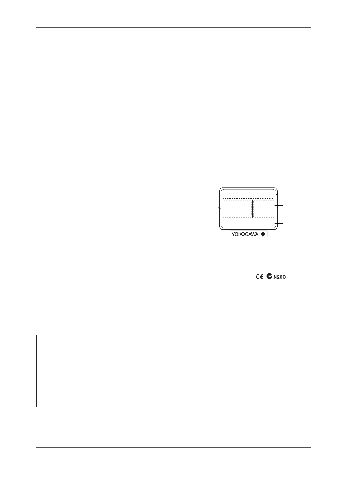
<13. General Specications>
13. General Specications
13-1
13.1 Functional Specications
Functional specications for Fieldbus
communication conform to the standard
specications (H1) of FOUNDATION eldbus.
Supply Voltage
9 to 32 V DC for general use, ame proof type,
Type n, or nonincendive.
9 to 24 V DC for intrinsically safe type Entity model
9 to 17.5 V DC for intrinsically safe type FISCO
model
Communication Requirements
Supply Voltage: 9 to 32 V DC
Current consumption:
Steady condition: 15 mA (max)
Software download condition: 24 mA (max)
Ambient Temperature Limits
-20 to 70°C (-4 to 158°F)
Ambient Humidity Limits
0 to 100 %RH
LCD Display
84 column x 32 lines full-dot matrix with LED
backlight.
3 lines indication as
• Top line
14 alphanumerics indication of main description
(Main Tag) such as PD TAG of eld device.
Scroll up to maximum 32 alphanumerics
• Middle line
5 digits process value including +/- sign and unit
of 5digits x 2 lines
• Bottom line
14 alphanumerics of communication status and
indicate description (Sub Tag) such as block
information.
Bar graph, Scroll bar, Page information, Scroll
direction information, Squawk
Top line
Unit
(Middle line)
Bottom line
Process value
(Middle line)
14 characters
5 digits
14 characters
5 digits
5 digits
Display Scroll Functions
Single scroll and cyclic scroll (Scan mode)
Display up to 16 variables
EMC Conformity Standard:
EN61326-1 Class A, Table 2
(For use in industrial location)
Link Master Function:
Link Master function is supported.
Function Block:
Block name Number Execution time Note
MAO
IS
AR
PID
SC
IT
2 30 ms Output eight analog signals from eld deveces
2 30 ms Input Selector block provides selection of up to eight inputsand generate
an output based on the congured action
2 30 ms Arithmetic block permits simple use of popular measurement math func-
tion
2 45 ms Works as a eld controller in conjunction with another function block.
1 30 ms An output of Signal Characterizer block is a nonlinear function of the
respective input. The function is determined by a table
1 30 ms Integrator block integrates a variable as a function of the time or accumu-
lates the counts
F1301.ai
IM 01S01C01-01EN
Page 86

<13. General Specications>
13.2 Physical Specications
Enclosure
Material
Housing: Low copper cast aluminum alloy with
polyurethane, mint-green paint (Munsell 5.6BG
3.3/2.9 or its equivalent) or ASTM CF-8M
stainless steel.
Body: 316L SST
Scroll Knob: 316L SST
Cover O-rings: Buna-N
Name plate and tag: 304 SST, 316 SST (for
optional code /HC)
Degrees of Protection
IP67, NEMA4X
Weight
1.2 kg (2.6 lb) *
*: Without mounting bracket.
Add 1.5 kg (3.3 lb) for Amplier housing code 2.
13-2
Electrical Connections
Refer to 13.3 Model and Sufx Codes.
13.3 Model and Sufx Codes
Model Sufx code Description
FVX110 . . . . . . . . . . . . . . . . . . . . Fieldbus segment indicator
Output
signal
Amplier
housing
Electrical
connection
Mounting bracket L
Optional Codes
-F
. . . . . . . . . . . . . . . . . .
1
. . . . . . . . . . . . . . . .
2 . . . . . . . . . . . . . . . .
0 . . . . . . . . . . . . .
2
. . . . . . . . . . . . .
4
. . . . . . . . . . . . .
5
. . . . . . . . . . . . .
7
. . . . . . . . . . . . .
9
. . . . . . . . . . . . .
A
. . . . . . . . . . . .
D
. . . . . . . . . . . .
C
. . . . . . . . . . . .
. . . . . . . . . .
N
. . . . . . . . . .
/
Digital communication (FOUNDATION Fieldbus protocol)
Cast aluminum alloy
ASTM CF-8M stainless steel
G 1/2 female, one electrical connection without blind plug
1/2 NPT female, two electrical connections without blind plugs
M20 female, two electrical connections without blind plugs
G 1/2 female, two electrical connections and a blind plug
1/2 NPT female, two electrical connections and a blind plug
M20 female, two electrical connections and a blind plug
G 1/2 female, two electrical connections and a 316 SST blind plug
1/2 NPT female, two electrical connections and a 316 SST blind plug
M20 female, two electrical connections and a 316 SST blind plug
316 SST 2-inch pipe mounting
None
Optional Specication
*1
*1: Not applicable for electrical connection code 0, 5, 7 or 9
IM 01S01C01-01EN
Page 87

<13. General Specications>
13.4 Optional Specications (For Explosion Protected type)
13-3
Item Description Code
1
1
1
1
1
Factory
Mutual (FM)
CENELEC
ATEX
Canadian
Standards
Association
(CSA)
FM Explosionproof Approval *
Applicable Standard: FM3600, FM3615, FM3810, ANSI/NEMA 250
Explosionproof for Class I, Division 1, Groups B, C and D,
Dust-ignitionproof for Class II/III, Division 1, Groups E, F and G, Enclosure Rating: NEMA Type 4X
Temperature class: T6, Amb. Temp.: –40 to 60°C (–40 to 140°F)
FM Intrinsically Safe and Nonincendive Approval *
Applicable Standard: FM3600, FM3610, FM3611, FM3810, ANSI/NEMA 250, ISA60079-27
Intrinsically Safe for Class I,II, & III, Division 1, Groups A,B,C,D,E,F & G, Entity, FISCO. /Class I, Zone 0,
AEx ia IIC,
Enclosure: "NEMA 4X", Temp. Class: T4, Amb. Temp.: –40 to 60°C (–40 to 140°F).
Intrinsically Apparatus Parameters :
[FISCO (IIC)] Ui=17.5 V, Ii=500 mA, Pi=5.5 W, Ci=1.76 nF, Li=0 µH
[FISCO (IIB)] Ui=17.5 V, Ii=500 mA, Pi=5.5 W, Ci=1.76 nF, Li=0 µH
[Entity] Ui=24 V, Ii=250 mA, Pi=1.2 W, Ci=1.76 nF, Li=0 µH
Nonincendive for Class I, Division 2, Groups A, B, C and D, NIFW, FNICO
Class I, Zone 2, Group IIC, NIFW, FNICO
Class II, Division 2, Groups F&G, and Class III, Division 1
Enclosure: "NEMA 4X", Temp. Class: T4, Amb. Temp.: –40 to 60°C (–40 to 140°F)
Nonincendive Apparatus Parameters : Vmax.=32 V, Ci=1.76 nF, Li=0 µH
CENELEC ATEX (KEMA) Flameproof Approval *
Applicable Standard: EN 60079-0, EN 60079-1, EN 61241-0, EN 61241-1
Certicate: KEMA 10ATEX0157
II 2G, 2D Ex d IIC T6 Ex tD A21 IP6X T80 Degree of protection : IP66 and IP67
Amb. Temp. (Tamb) for gas-proof : T6; –50 to 75°C (–58 to 167°F)
Max. surface Temp. for dust-proof : T80°C (Tamb: –40 to 167°F)
CENELEC ATEX (DEKRA) Intrinsically safe Approval *
Certicate: DEKRA 11ATEX0022 X
Applicable standards: EN 60079-0, EN 60079-11, EN 60079-26, EN 60079-27, EN 61241-11
II 1G Ex ia IIB/IIC T4 Ga, II 1D Ex ia IIIC T80°C Da IP6X
Amb. Temp.: –40 to 60°C (–40 to 140°F)
Max. Surface Temp. for dust-proof: T80°C (Tamb.: –40 to 140°F)
Enclosure: IP66 and IP67
[FISCO (IIC)] Ui=17.5 V, Ii=500 mA, Pi=5.5 W, Ci=3.52 nF, Li=0 µH
[FISCO (IIB)] Ui=17.5 V, Ii=500 mA, Pi=5.5 W, Ci=3.52 nF, Li=0 µH
[Entity] Ui=24 V, Ii=250 mA, Pi=1.2 W, Ci=3.52 nF, Li=0 µH
CSA Explosionproof Approval *
Certicate: 2325751
Applicable Standard: C22.2 No.0, C22.2 No.0.4, C22.2 No.0.5, C22.2 No.25, C22.2 No.30, C22.2 No.94,
C22.2 No.213, C22.2 No.60079-0, C22.2 No.60079-1, C22.2 No.61010-1-04
Explosion-proof for Class I, Groups B, C and D.
Dustignition-proof for Class II/III, Groups E, F and G.
When installed in Division 2, "SEAL NOT REQUIRED" Enclosure: TYPE 4X, Temp. Class: T6
Ex d IIC T6 Enclosure: IP66 and IP67
Amb.Temp.: –50 to 75°C (–58 to 167°F)
CSA Intrinsically safe Approval *1
Certicate: 2346277
Applicable Standard: C22.2 No.0, C22.2 No.0.4, C22.2 No.25, C22.2 No.94, C22.2 No.157, C22.2 No.213,
C22.2 No.61010-1-04
CAN/CSA E60079-0, CAN/CSA E60079-11, CAN/CSA E60079-15, IEC 60529
Intrinsically Safe for Class I, Division 1, Groups A, B, C & D, Class II, Division 1, Groups E, F & G,
Class III Division 4; Ex ia IIC T4
Amb. Temp.: –40 to 60°C (–40 to 140°F) Encl. Type 4X, IP66 and IP67
Entity Parameters for Intrinsically Safe:
Ui (Vmax)=24 V, Ii (Imax)=250 mA, Pi (Pmax)=1.2 W, Ci=1.76 nF, Li=0 µH or
Ui (Vmax)=17.5 V, Ii (Imax)=500 mA, Pi (Pmax)=5.5 W, Ci=1.76 nF, Li=0 µH
Nonincendive for Class I, Division 2, Groups A, B, C & D, Class II, Division 2, Groups F & G,
Class III Division 1; Ex nL IIC T4
Amb. Temp.: –40 to 60°C (–40 to 140°F) Encl. Type 4X, IP66 and IP67
Entity Parameters for Nonincendive: Ui=32 V, Ci=1.76 nF, Li=0 µH
FF1
FS15
KF25
KS25
CF1
CS15
IM 01S01C01-01EN
Page 88

<13. General Specications>
13-4
Item Description Code
IECEx Flameproof Approval *
Applicable Standard: IEC 60079-0, IEC60079-1
Certicate: IECEx KEM 10.0071
Flameproof for Zone 1, Ex d IIC T6 Enclosure: IP66 and IP67
Amb.Temp.: –50 to 75°C (–58 to 167°F)
IECEx Intrinsically safe and type n Approval *1
IECEx
Scheme
*1: Applicable for Electrical connection code 2, 4, 7, 9, C and D.
No. IECEx DEK 11.0004 X
Applicable Standard: IEC 60079-0, IEC 60079-11, IEC 60079-26, IEC 60079-27,
Ex ia IIB/IIC T4, Ga Ex ic IIC T4 GC
Ambient Temperature: –40 to 60°C
Enclosure: IP66 and IP67
Intrinsically safe ratings (Ex ia IIB/IIC T4)
[Entity] Ui=24 V, Ii=250 mA, Pi=1.2 W, Ci=3.52 nF, Li=0 µH
[FISCO IIC] Ui=17.5 V, Ii=500 mA, Pi=5.5 W, Ci=3.52 nF, Li=0 µH
[FISCO IIB] Ui=17.5 V, Ii=500 mA, Pi=5.5 W, Ci=3.52 nF, Li=0 µH
Intrinsically safe ratings (Ex ic IIC T4): Ui=32 V, Ci=3.52 nF, Li=0 µH
1
13.5 Optional Specications
Item Description Optional code
Painting Color change Amplier cover only
Amplier cover and terminal cover, Munsell 7.5 R4/14
Coating change Anti-corrosion coating
316 SST exterior parts 316 SST name plate, tag plate and screw
Lightning protector Power supply voltage: 10.5 to 32 V DC (10.5 to 30 V DC for intrinsically safe
type, 9 to 32 V DC for Fieldbus communication type)
Allowable current: Max. 6000A (1x40μs), Repeating 1000A (1x40μs) 100times
Wired tag plate 304 SST tag plate wired onto indicator (316 SST when /HC is specied)
*1: Not applicable for amplier housing code 2
*2: Not applicable with color change option
*3: 316 SST or 316L SST. The specication is included in amplier housing code 2.
*1
*1*2
*3
SF25
SS25
P□
PR
X2
HC
A
N4
IM 01S01C01-01EN
Page 89

<13. General Specications>
13.6 Dimensions
13-5
Conduit connection
Mounting bracket
(optional)
(2.36)
126 (4.96)
95 (3.74)
60
50
(1.97)
12
(0.47)
Scroll knob
Conduit connection
139 (5.47)
159 (6.26)
(O.D. 60.5 mm)
54
(2.13)
6
(0.24)
Ø78 (3.07)
Ground
terminal
Body
2-inch pipe
110 (4.33)
12
(0.47)
Unit: mm (approx.inch)
188 (7.40)
39
(1.54)
Ø70 (2.76)
110 (4.33)
129 (5.08)
Electrical connection for code 5, 9, A and D
● Terminal Conguration ● Terminal Wiring
Communication terminals
connection hook
SUPPLY +
SUPPLY –
SUPPLY
<Factory Setting>
Tag Number
Software Tag
Node Address '0xF5' unless otherwise specied in
+
–
(Tag plate)
(PD_TAG)
Operation
Functional
Class
Power supply and output terminal
Ground terminal
'UI1001' unless otherwise both Tag
Number
and software Tag specied in order
order
BASIC or as specied
F1302.ai
F1303.ai
As specied in order
IM 01S01C01-01EN
Page 90
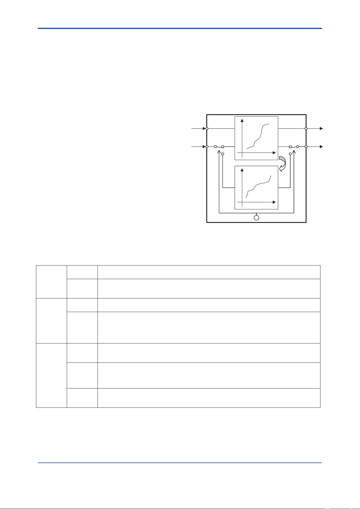
<Appendix 1. Signal Characterizer (SC) Block>
Appendix 1. Signal Characterizer (SC)
Block
A1-1
The Signal Characterizer (SC) block is used to
convert the values of input signals according to a
line-segment function. The line-segment function
is created using 21 points of the X/Y coordinates
specied by the user. This function block can also
be used as a transmission line for control signals
and supports backward control.
Application
The Signal Characterizer block is primarily used
if you wish for one of the following reasons to
correct signals using the coordinates rather than a
computational expression:
• The computational expression for correction in
relation to input signals is complex
• The relationship between input signals and
the signals after correction is only empirically
known
A1.1 Schematic Diagram of
Signal Characterizer Block
The following shows the schematic diagram of the
Signal Characterizer block.
IN_1
IN_2
Figure A1.1 Signal Characterizer Block
y
OFF OFF
ON
x
Inverse
function
SWAP_2
ON
x
y
OUT_1
OUT_2
FA0101.ai
Input/Output Parameters
Input IN_1 Inputs a signal desired to be corrected using a line-segment function.
IN_2 Inputs a signal desired to be corrected using a line-segment function.
Output OUT_1 Outputs the result of the IN_1 input that has been corrected using the line-segment function.
OUT_2 Outputs the result of the IN_2 input that has been corrected using the line-segment function.
Others CURVE_X The points of the curve determining inputs and outputs.
CURVE_Y The points of the curve determining inputs and outputs.
SWAP_2 Selector switch used to specify if an inverse function is used for the line-segment
(It is substituted for X of the line-segment function.)
(If SWAP_2 = off, it is substituted for X of the line-segment function.)
(If SWAP_2 = on, it is substituted for Y of the line-segment function.)
(The function block outputs the value of Y corresponding to IN_1.)
The output can also be approximated using the inverse function of the specied line-segment
function. (This is used for backward control.)
(If SWAP_2 = off, the value of Y corresponding to X of IN_1 is output.)
(If SWAP_2 = on, the value of X corresponding to Y of IN_1 is output.)
The x points of the curve are dened by an array of 1 to 21 points with a monotone increase.
"+INFINITY" is congured for unused point(s).
The y points of the curve are dened by an array of 1 to 21 points.
If SWAP_2 = on, the elements of the curve are dened with a monotone increase or decrease.
"+INFINITY" is congured for unused point(s).
approximation of IN_2 to OUT_2.
The setting of SWAP_2 = on (which uses the inverse function) is used for backward control.
IM 01S01C01-01EN
Page 91

<Appendix 1. Signal Characterizer (SC) Block>
Line-segment factor
determination section
Determining
the gradient
and intercept
Output section
OUT
processing
Determining the
status and
computing OUT
OUT_1
OUT_2
IN_1
IN_2
Input section
Determining
the mode
BLOCK_ERR
A1-2
Y
or
X
X or Y
CURVE_X
CURVE_Y
Figure A1.2 Overview of the Signal Characterizer Block
SWAP_2
The following describes the Signal Characterizer
block, dividing its functions into three sections:
• Input section: Determines the mode and judges
BLOCK_ERR.
• Line-segment factor determination section:
Determines the gradient and intercept for
OUT_1 and
OUT_2 based on CURVE_X, CURVE_Y, and
SWAP_2 at shift .
• Output section: Multiplies the input values in
IN_1 and IN_2 by the gradient and adds the
intercept to them before outputting the results.
Alternatively, it outputs a limit value.
A1.2 Input Section
The input section determines the mode and judges
BLOCK_ERR.
A1.2.1 Determining the Mode
MODE = AUTO
MODE = MAN or O/S
FA0102.ai
A1.2.2 Judging BLOCK_ERR
BLOCK_ERR indicates the cause of an error in the
function block. If the cause of an error indicated by
BLOCK_ERR occurs, the following conguration
error is generated.
Name Description
Block
Conguration
Error
1) “–INFINITY” has been congured for
CURVE_X and CURVE_Y.
2)
“+INFINITY” has been congured for
X1 of CURVE_X.
3)
“+INFINITY” has been congured for
Y1 of CURVE_Y.
4)
A value of the array of CURVE_X
does not increase in a monotone
manner.
5)
A conguration error when SWAP_2
is on"
• A value of the array of CURVE_Y
does not increase or decrease in a
monotone manner.
6)
The value of SWAP_2 is any value
other than 1 or 2.
The following describes operations of the Signal
Characterizer block.
Supported Mode Rules
O/S
(Out of Service)
Man •
Auto •
• System-stopped status
• Conguration change
If you do not want to output the
value and the status from IN, you
can manually transmit the value to
OUT.
Automatic system operation status
The mode changes to O/S if a block conguration
error occurs.
IM 01S01C01-01EN
Page 92
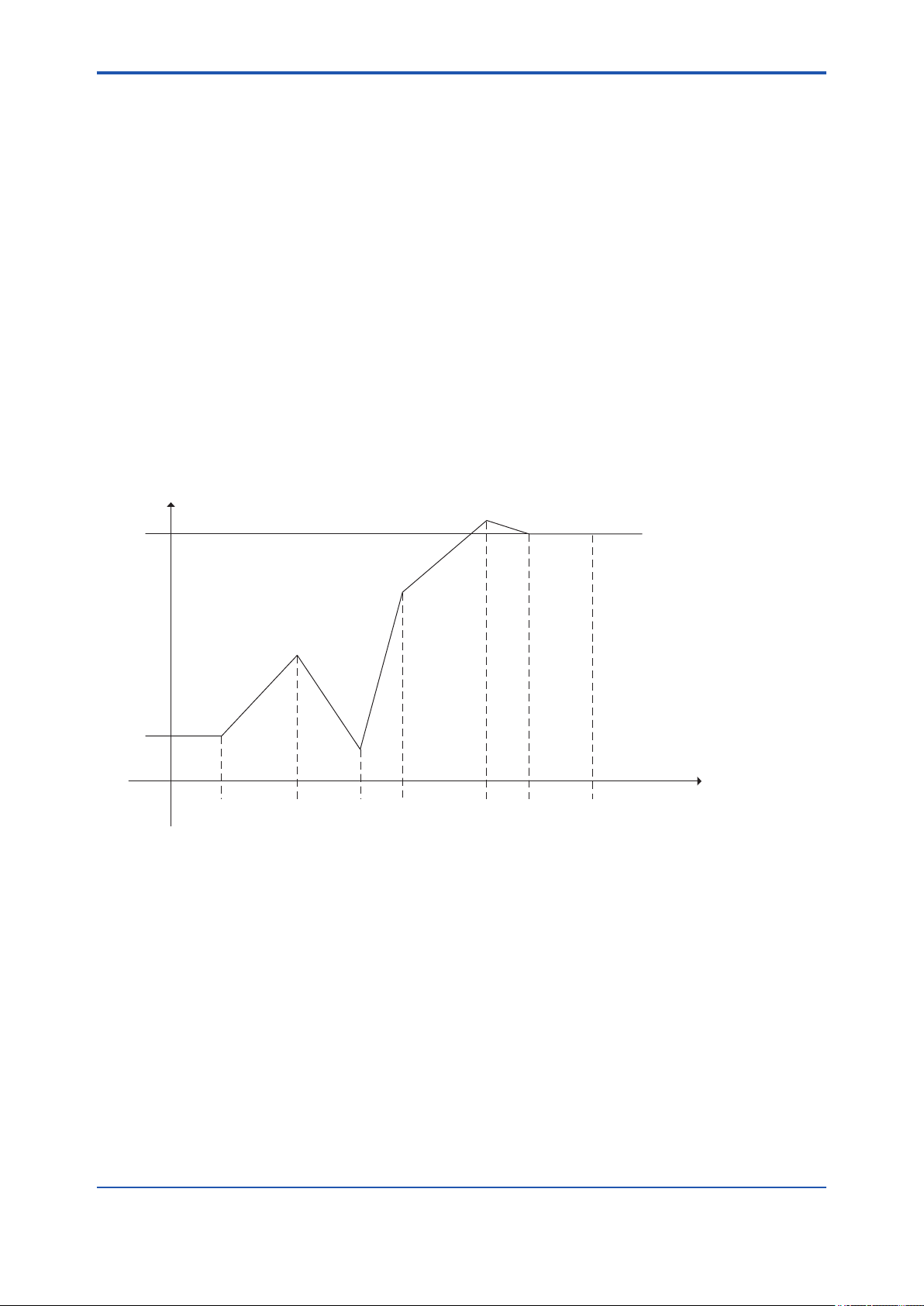
<Appendix 1. Signal Characterizer (SC) Block>
A1-3
A1.3 Line-segment Factor Determination Section
When the mode is AUTO and no bit in BLOCK_ERR is set, the "gradient" and "intercept" of a line passing
through two points that are considered line-segment approximation values are determined.
A1.3.1 Conditions for Conguring Valid Coefcients (CURVE_X, CURVE_Y)
No write error is generated with respect to the settings in CURVE_X and CURVE_Y. However, a conguration
error occurs in the following cases:
1. "+INFINITY" has been congured for X1 or Y1.
2. "–INFINITY" has been congured for each X or Y.
3. The values of CURVE_X are not increasing in a monotone manner (X1 < X2 < ... < X20 < X21).
(If SWAP_2 is off, it is acceptable if the values of CURVE_Y do not increase or decrease in a monotone
manner.)
4. The values of CURVE_Y are not increasing or decreasing in a monotone manner when SWAP_2 is on.
If a conguration error occurs, the Block Conguration Error bit in BLOCK_ERR is set, causing the mode to
change to O/S.
Example of the case where SWAP_2 is off:
Y
Output
Y6
(High limit)
Y1
(Low limit)
X1 X2 X3 X4 X5 X6 X7 =INFINITY X
Input
FA0103.ai
Figure A1.3 Example of Curve (SWAP_2 = off)
The range of CURVE_X: X1 to X6 (X7 and above are invalid because "+INFINITY" has been congured for
X7*1.)
The X1 to X6 values always increase in a monotone manner (X1 < X2 < X3 < X4 < X5 < X6).
If an input value is smaller than X1, it is set to Y1.
If an input value is larger than X6, it is set to Y6.
The range of CURVE_Y: Y1 to Y6
It is acceptable if the Y1 to Y6 values do not increase in a monotone manner.
However, if the setting of SWAP_2 is changed from off to on, the values of CURVE_Y must increase or
decrease in a monotone manner. Thus, if a value of CURVE_Y does not increase or decrease in a monotone
manner in this setting, the mode changes to O/S, causing the Block Conguration Error bit in BLOCK_ERR to
be set.
*1: For any points of the curve that are not used, congure "+INFINITY" for all of them.
IM 01S01C01-01EN
Page 93

<Appendix 1. Signal Characterizer (SC) Block>
A1-4
Example of the case where SWAP_2 is on (monotone increase):
The input range of IN_1 is always in CURVE_X. The following shows the input/output graph of the IN_1 values.
Y
Output
Y6
(High limit)
Y1
(Low limit)
X1 X2 X3 X4 X5 X6 X7 =INFINITY X
Input
FA0104.ai
Figure A1.4 Example of Curve for IN_1 (SWAP_2 = on)
The input range of IN_2 is always in CURVE_Y. The following shows the input/output graph of the IN_2 values.
Output
X
X6
X5
X4
X3
X2
X1
Y Input
Y1
(Low limit)
Figure A1.5 Example of Curve for IN_2 (SWAP_2 = on)
Y2 Y3 Y4 Y5 Y6 Y7 =INFINITY
(High limit)
FA0105.ai
When SWAP_2 is on, the array elements of CURVE_Y must be congured for a monotone increase or
decrease. (Y1 < Y2 < Y3 < Y4 < Y5 < Y6 or Y6 < Y5 < Y4 < Y3 < Y2 < Y1)
IM 01S01C01-01EN
Page 94

<Appendix 1. Signal Characterizer (SC) Block>
A1.4 List of Signal Characterizer Block Parameters
A1-5
Relative
Index
0 BLOCK_
1 ST_REV - - - - - 2 2 2 2 The revision level of the set parameters associated
2 TAG_DESC Null Stores comments describing tag information.
3 STRATEGY 1 2 The strategy eld can be used by the high-level
4 ALERT_KEY 1-255 1 1 Key information used to identify the location at which
5 MODE_BLK 4 4 Mode of the Signal Characterizer block. O/S, Man,
6 BLOCK_ERR 2 2 Indicates the error status of the Signal Characterizer
7 OUT_1 MAN 5 5 Outputs the result of the value of IN_1 corrected
8 OUT_2 MAN 5 5 Outputs the result of the value of IN_2 corrected
9 X_RANGE 100
10 Y_RANGE 100
11 GRANT_DENY 2 The parameter used to check if various operations
12 IN_1 5 5 Input a signal to be corrected using a line-segment
13 IN_2 5 5 Input a signal to be corrected using a line-segment
14 SWAP_2 0:Initialized
15 CURVE_X Curve input points that determine inputs and
16 CURVE_Y Curve input points that determine inputs and
17 UPDATE_EVT Indicates event information if an update event
18 BLOCK_ALM Indicates alarm information if a block alarm occurs.
Parameter
HEADER
Write
Mode
Block
Tag=O/S
Valid Range
0
1342
1
0
1342
1
1:No swap
2:Swap
Initial
Value
TAG: "SC" Information relating to this function block, such as
View
1 2 3 4
block tag, DD revision, and execution time
with the Signal Characterizer block
system to identify function blocks.
an alert has occurred
and Auto are supported.
block in bit strings.
using a line-segment function.
using a line-segment function. It is also possible to
approximate the result using the inverse function of
the specied line-segment function. (This is used for
backward control.)
11 The engineering unit of variables corresponding to
the X-axis for display
11 The engineering unit of variables corresponding to
the Y-axis for display
have been executed.
The bits in the GRANT parameter corresponding to
various operations are set before being executed.
After the operations are complete, the DENY
parameter is checked for the setting of any bit
relating to the corresponding operation. If no bit
is set, it is evident that the operations have been
executed successfully.
function.
function.
1 Selector switch used to apply the inverse function to
line-segment approximation of IN_2 to OUT_2
outputs.
The "x" points of the curve are dened by an array of
1 to 21 points with a monotone increase.
outputs.
The "y" points of the curve are dened by an array of
1 to 21 points.
If SWAP_2 is on, the elements of the curve must be
dened with a monotone increase or decrease.
occurs.
Description / Remarks
IM 01S01C01-01EN
Page 95

<Appendix 1. Signal Characterizer (SC) Block>
A1-6
A1.5 Application Example
A1.5.1 Input Compensation
The following is an application example of pH
compensation made by performing feedback
control.
The pH is a value representing the degree of acidity
or alkalinity and ranges from 0 to 14. pH 7 indicates
neutral, a value smaller than 7 represents acidity,
and a value larger than 7 denotes alkalinity. It is
very difcult to control pH with a quickly changing
reaction rate at a point near 7.
14
13
12
11
10
9
8
pH
7
6
5
4
3
2
1
0 0.2 0.4 0.6 0.8 1.0 1.2 1.4 1.6 1.8 2.0
Ratio of Reagent to Influent Flow
Figure A1.6 pH and Reagent Flow
Small increases in reagent
flow cause large pH shifts
FA0106.ai
The following shows the approximation-value graph
of GX Output that is approximation-value output
and GX Input that is pH input. pH with a quickly
changing reaction rate can be controlled at a point
near neutral 7 according to the following graph.
100
90
80
70
60
50
CURVE_Y
40
30
20
10
0 10 20 30 40 50 60 70 80 90 100
0 to 100% = 0 to 14 pH
CURVE_X
FA0108.ai
Figure A1.8 Approximation Curve
A1.5.2 Calorie Flow Compensation
AI_1: Inlet temperature, AI_2: Outlet temperature,
AI_3: Flow rate
SC: Corrects the inlet and outlet temperatures.
AR: Calculates a calorie ow rate on the basis of
the difference between the corrected inlet and outlet
temperatures.
To control this pH, the input is regulated using
line-segment approximation, gain, and input
compensation.
Characterizer
GX
X Gain
DM
Figure A1.7 Input Compensation
pH Input
PID
Control
Control
Output
Input Compensation
FA0107.ai
SWAP_2=OFF
IN_1
IN_2
SC
AI3
OUT_1
OUT_2
OUT
AR
IN_1
IN_2 OUT
IN
FA0109.ai
AI1
OUT
AI2
OUT
Figure A1.9 Calorie Flow Rate Compensation
(SWAP_2 = Off)
IM 01S01C01-01EN
Page 96

<Appendix 1. Signal Characterizer (SC) Block>
A1-7
A1.5.3 Backward Control
SC: The controlled variable output from PID is
converted into an information quantity that can be
interpreted by AO, and backward information from
AO is converted into an information quantity that
can be interpreted by PID before being transmitted
to the PID.
AI
OUT
PID
OUTIN
BKCAL_IN
SC
OUT_1IN_1
OUT_2
SWAP_2=ON
IN_2
Figure A1.10 Backward Control (SWAP_2 = On)
To enable backward control (which inverts the X
and Y axes), the line-segment function must be
set so that the elements of the curve increase in a
monotone manner.(As shown in Figure A1.11) If
they do not increase in a monotone manner, the
mode changes to O/S, disabling calculation.
AO
CAS_IN
BKCAL_OUT
FA0110.ai
Line-segment function
100
90
80
70
60
50
CURVE_Y
40
30
20
10
0 10 20 30 40 50 60 70 80 90 100
CURVE_X
X_RANGE = 100, 0, %, 0x00
Y_RANGE = 100, 0, %, 0x00
Figure A1.11 Setting Example of a Line-segment
Function
FA0111.ai
No. CURVE_X CURVE_Y
1 5 5
2 10 10
3 15 11
4 20 20
5 25 25
6 30 26
7 35 30
8 40 40
9 45 45
10 50 50
11 51 51
12 52 54
13 53 59
14 54 66
15 55 75
16 65 80
17 75 81
18 80 85
19 85 86
20 90 90
21 95 95
IM 01S01C01-01EN
Page 97

<Appendix 2. Integrator (IT) Block>
A2-1
Appendix 2. Integrator (IT) Block
The Integrator (IT) block adds two main inputs and integrates them for output. The block compares the
integrated or accumulated value to TOTAL_SP and PRE_TRIP and generates discrete output signals OUT_
TRIP or OUT_PTRIP when the limits are reached.
The output is as represented by the following equation (for counting upward and rate conversion).
OUT.Value = Integration start value + Total
Total = Total + Current Integral
Current Integral = (x + y) × Δt
x: IN_1 value whose unit has been converted
y: IN_2 value whose unit has been converted
Δt: block execution period
A2.1 Schematic Diagram of Integrator Block
The following shows the schematic diagram of the Integrator block.
INTEG_OPTS
(INPUT TYPE)
–1
INTEG_OPTS
(INPUT TYPE)
–1
Forward
Reverse
Forward
Reverse
INTEG_OPTS
(FROW TYPE)
Add
UNIT_CONV
INTEG_TYPE
INTEG_OPTS (QUALITY)
GOOD_LIM
UNCERT_LIM
CLOCK_PER
Integrate
TOTAL / RTOTAL
INTEG_OPTS
(CARRY)
OP_CMD_INT
(RESET)
N_RESET
PRE_TRIP
Compare
TOTAL_SP
Compare
MAN
OUT
MAN
OUT_PTRIP
MAN
OUT_TRIP
IN_1
REV_FLOW1
IN_2
REV_FLOW2
RESET_IN
TIME_UNIT1
Convert Rate
Convert Accum
PULSE_VAL1
TIME_UNIT2
Convert Rate
Convert Accum
PULSE_VAL2
RESET_CONFIRM
IN_1: Block input 1 (value and status)
IN_2: Block input 2 (value and status)
REV_FLOW1: Indicates whether the sign of IN_1 is reversed. It is a discrete signal.
REV_FLOW2: Indicates whether the sign of IN_2 is reversed. It is a discrete signal.
RESET_IN: Resets the integrated values. It is a discrete signal.
RESET_CONFIRM: Reset conrmation input. It is a discrete signal.
OUT: Block output (value and status)
OUT_PTRIP: Set if the target value exceeds PRE_TRIP. It is a discrete signal.
OUT_TRIP: Set if the target value exceeds TOTAL_SP (or 0). It is a discrete signal.
The Integrator block is classied into the following ve sections for each function:
• Input process section: Determines the input value status, converts the rate and accumulation, and
determines the input ow direction.
• Adder: Adds the two inputs.
• Integrator: Integrates the result of the adder into the integrated value.
• Output process section: Determines the status and value of each output parameter.
• Reset process section: Resets the integrated values.
Figure A2.1 Integrator Block
FA0201.ai
IM 01S01C01-01EN
Page 98

<Appendix 2. Integrator (IT) Block>
A2-2
A2.2 Input Process Section
When executed, the Integrator block rst performs input processing in the order of:
"Determining input status" → "Converting Rate or Accum" → "Determining the input ow direction"
Switching between Convert Rate and Convert Accum is made using bit 0 (for IN_1) or bit 1 (for IN_2) of
INTEG_OPTS. INTEG_OPTS is one of the system parameters and should be set by the user. The values of
IN_1 and IN_2 are not retained if the power is turned OFF.
A2.2.1 Determining Input Value Statuses
The following shows the correlation between the statuses of input parameters (IN_1, IN_2) and the statuses of
input values used in the Integrator block.
Statuses of Input
Parameters (IN_1, IN_2)
Bit 4 of INTEG_OPTS
(Use Uncertain)
Bit 5* of INTEG_OPTS
(Use Bad)
Status of Input Values
Handled in IT Block
Good Irrelevant Irrelevant Good
Bad Irrelevant H (=1) Good
Bad Irrelevant L (=0) Bad
Uncertain H (=1) Irrelevant Good
Uncertain L (=0) Irrelevant Bad
For addition (see A2.3), if the status of an input value is "Bad," the "Good" value just before the status changed
to "Bad" is used.
* Even if the Use Bad option is used, changing the internal status to "Good," the value of "Good" just before
the status changed to "Bad" is used.
A2.2.2 Converting the Rate
The following describes an example of rate conversion.
In rate conversion, rstly convert the unit of two inputs to that based on seconds.
Next, convert the unit of the inputs to the same unit to be added together. The unit of IN_2 is standardized to
that of IN_1. Then, calculates a weight, volume, or energy by multiplying each input value and block execution
time. Because unit information is not input to the Integrator block as an input value, the user must input in
advance tuned values to the TIME_UNIT1/2 and UNIT_CONV parameters.
Converts the unit into
that based on seconds
TIME_UNIT1
input1
kg/hour
input2
lb/min
lb: pounds
sec:÷1
min:÷60
hour:÷3600
day:÷86400
Converts the unit into
that based on seconds
TIME_UNIT2
sec:÷1
min:÷60
hour:÷3600
day:÷86400
Standardizes the unit of
IN_2 to that of IN_1.
Because "lb/s" is converted into
"kg/s" in this example, the input
2 value is multiplied by 0.453.
(1 lb = 0.453 kg)
UNIT_CONV
lb/s kg/s kg
x [conversion factor]
(Conversion factor:
0.453 in this example)
Figure A2.2 Increment Calculation with Rate Input
kg/s kg
× block execution time
× block execution time
increment1
increment2
IM 01S01C01-01EN
FA0202.ai
Page 99

<Appendix 2. Integrator (IT) Block>
A2-3
A2.2.3 Converting Accumulation
This following describes an example of accumulation conversion.
In accumulation conversion, the difference between the value executed previously and the value executed
this time is integrated or accumulated. This conversion applies when the output of a function block used as a
counter is input to the input process of the Integrator block.
In order to convert the rate of change of an input to a value with an engineering unit, the user must congure
the factor of conversion to the appropriate engineering unit in the PULSE_VAL1 and PULSE_VAL2
parameters.
Moreover, the unit of IN_2 is standardized to that of IN_1 in the same way as rate conversion. Thus, the user
must also set an appropriate value to UNIT_CONV.
input1
counts number of pulse kg
input2
counts number of pulse lb kg
Figure A2.3 Increment Calculation with Counter Input
[Current read value] – [Previous read value]
[Current read value] – [Previous read value]
PULSE_VAL1(#19)
× [pulse value1]
kg/pulse
PULSE_VAL2(#20)
× [pulse value2]
lb/pulse
UNIT_CONV(#18)
× [conversion factor]
increment1
increment2
FA0203.ai
A2.2.4 Determining the Input Flow Direction
The Integrator block also considers the input ow direction. Information about the input ow direction is
contained in REV_FLOW1 and REV_FLOW2 (0: FORWARD, 1: REVERSE).
In input processing, the sign of the value after rate and accumulation conversion is reversed if the REV_
FLOW1 and REV_FLOW2 parameters are set to REVERSE. When determination of the ow direction of two
input values is complete, these two inputs are passed to the adder. The settings in REV_FLOW will be retained
even if the power is turned OFF.
A2.3 Adder
When input processing is complete, two arguments that have been rate and accumulate converted will be
passed to the adder. The adder adds these two values according to the option.
A2.3.1 Status of Value after Addition
If one of the statuses of two arguments is "Bad" or if two of them are both "Bad," the status of the value after
addition becomes "Bad." In this case, the value of "Good" just before the status changed to "Bad" is used as
the addition value (see A2.1).
When the statuses of two arguments are both "Good," the status of the value after addition becomes "Good."
In this case, the status of the value after addition will be used for the status applied to integration.
IM 01S01C01-01EN
Page 100

<Appendix 2. Integrator (IT) Block>
A2.3.2 Addition
The following three options are available for addition:
• TOTAL: Adds two argument values as is.
• FORWARD: Adds two argument values, regarding a negative value as "0."
• REVERSE: Adds two argument values, regarding a positive value as "0."
You can choose these options using bit 2 and bit 3 of INTEG_OPTS as follows:
A2-4
Bit 2 of INTEG_OPTS
(Flow Forward)
H H TOTAL
L L TOTAL
H L FORWARD
L H REVERSE
Bit 3 of INTEG_OPTS
(Flow Reverse)
Adder Options
The result of the adder is passed to the integrator. If only one of the inputs is connected, the value of a nonconnected input will be ignored.
When bit 7 of INTEG_OPTS (Add zero if bad) has been set, if the status of a value after addition is "Bad," the
value after addition (increment) becomes "0."
A2.4 Integrator
When addition is complete, its result will be passed to the integrator.
Integration consists of combinations of a reset method and counting up/down. There are the following seven
integration types, which can be set using INTEG_TYPE.
1. UP_AUTO: Counts up with automatic reset when TOTAL_SP is reached
2. UP_DEM: Counts up with demand reset
3. DN_AUTO: Counts down with automatic reset when zero is reached
4. DN_DEM: Counts down with demand reset
5. PERIODIC: Counts up and is reset periodically according to CLOCK_PER
6. DEMAND: Counts up and is reset on demand
7. PER&DEM: Counts up and is reset periodically or on demand
Each type of integration is independently run as a function.
There are the following four types of integrated values:
1. Total: Integrates the result of the adder as is.
2. ATotal: Integrates the absolute value of the result of the adder.
3. RTotal: Integrates the absolute value of the result of the adder only if the status of the result is "Bad."
This value is used for the RTOTAL value.
4. AccTotal: An extension function. The result of the adder is integrated as is and will not be reset.
The value is used for the ACCUM_TOTAL (expanded parameter) value.
The table A2.1 shows the details of INTEG_TYPE.
IM 01S01C01-01EN
 Loading...