

Page 1
Instruction
Manual
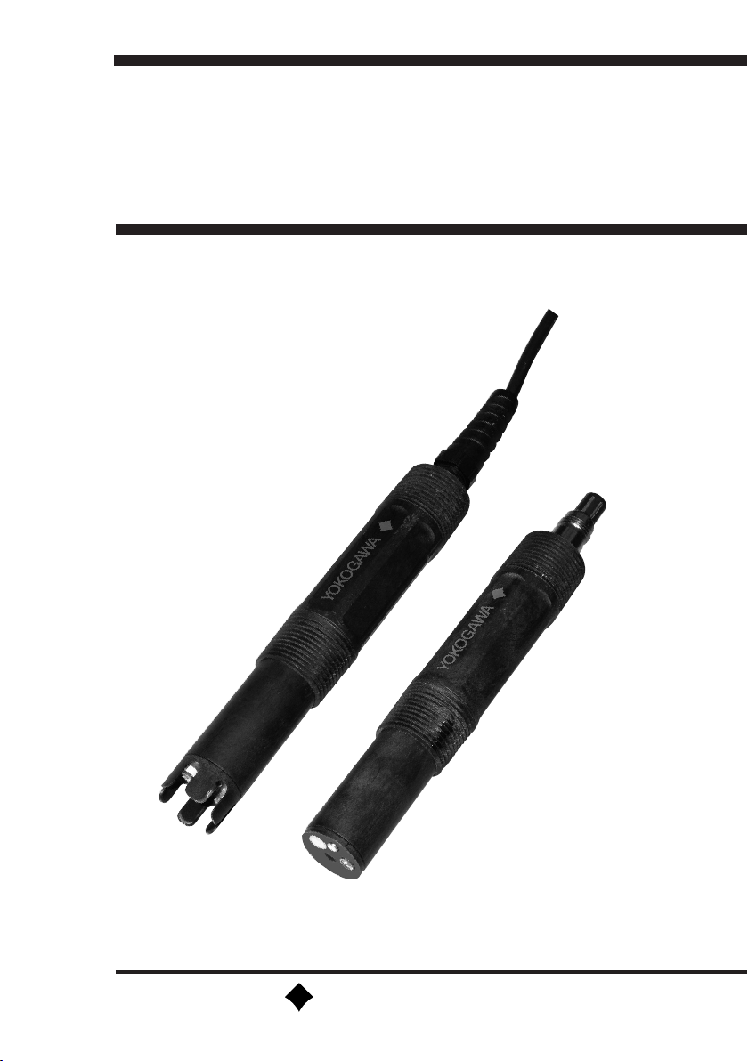
Model FU24
Combined pH/ORP Sensor
with Pressure Compensation
YOKOGAWA
IM 12B6J3-03E-E
5th edition
Page 2

Page 3

Table of Contents
1 GENERAL 2
1.1 Introduction 2
1.2 Unpacking & Checking 2
1.3 Warranty & Service 2
2 GENERAL SPECIFICATIONS 3
2.1 Measuring elements
2.2 Construction materials 3
2.3 Functional specifications 3
2.4 Dynamic specifications 3
2.5 Operating range 3
2.6 Mechanical 3
2.7 Dimensions 4
3 INSTALLATION OF THE FU24 5
3.1 Typical installation 5
3.2 Mounting the sensor 5
3.3 Preparing the sensor for use 5
1
4 WIRING 6
4.1 Cable marking and pin allocation 6
4.2 Instrument connection of sensor vs. measurement 6
4.2.1. Settings for PH402G and PH202G(S) 7
4.2.2. Settings for PH450G, PH150 and FLXA21 7
5 GENERAL CALIBRATION AND MAINTENANCE PROCEDURE 8
5.1 Calibration for pH measurement 8
5.2 Calibration for ORP and rH measurements 8
5.3 Maintenance 8
6 MODEL AND SUFFIX CODES 9
6.1 FU24 sensor 9
6.2 Cable for Sensor with Variopin Connector 9
7 SPARE PARTS 9
IM 12B6J3-03E-E
Page 4

2
1 GENERAL
1.1 Introduction
The FU24 is a four-in-one wide body pH
sensor. The wide body sensor holds four
separate measuring elements and an internal
compensation mechanism for fluctuating
process conditions in one unbreakable and
chemical resistant PPS 40GF (RytonTM) body.
By design, the FU24 is particularly useful in
harsh applications with fluctuating pressure and/
or temperature. Normally these processes can
be “killing” for a sensor. Process fluid may be
moving in and out of the sensor under influence
of frequent pressure and/or temperature
fluctuations. This results in fast desalting and
dilution of the reference electrolyte. This in turn
will change the reference voltage and cause a
drifting pH measurement.
By using the successful Yokogawa patented
Bellow system integrated in the FU24 sensor,
a strong pressure compensation mechanism is
created. The build-in bellow ensures immediate
interior pressure equalization to the outside
pressure, making the sensor virtually insensitive
to external pressure variations.
A slight overpressure caused by the bellow
tension, prevents fluid ingress and maintains a
positive ion flow out of the sensor. This feature is
of particular interest in pure water applications.
This all-in-one sensor provides simultaneous
measurement of pH, redox (ORP) and
temperature if desired. It is designed for easy
installation via the 1”NPT threaded connections
provided on both ends of the sensor body.
The FU24-series is available with an integral
cable of various lengths or with a multipole VP
connector.
1.2 Unpacking & Checking
Upon delivery, unpack the sensor carefully and
inspect it to ensure it was not damaged during
shipment. If damage is found, retain the original
packing materials (including outer box) and
immediately notify the carrier and the relevant
Yokogawa sales office. Make sure the Model
Code on the sensor is the same as on the
packing list. The Model Code and Serial Number
are found on the cable or the VP-connector
of the sensor. Check that option(s) that were
ordered, are also included.
1.3 Warranty & Service
Yokogawa products and parts are guaranteed
free from defects in workmanship and materials
under normal use and service for a period
of (typically) 12 months from the date of
shipment from the manufacturer. Individual
sales organizations can deviate from the typical
warranty period, and the conditions of sale
relating to the original purchase order should
be consulted. Damage caused by wear and
tear, inadequate maintenance, corrosion, or by
the effects of chemical processes are excluded
from this warranty coverage. In the event of
warranty claim, the defective goods should be
sent (freight paid) to the Service Department
of the relevant Sales Organization for repair or
replacement (at Yokogawa’s discretion).
The following information must be included in
the letter accompanying the returned goods:
• Model Code and Serial Number.
• Original Purchase Order and Date.
• Length of time in service and description of
the process.
• Description of the fault and circumstances of
the failure.
• Process/environmental conditions that may be
related to the failure of the sensor.
IM 12B6J3-03E-E
Page 5

• Statement as to whether warranty or non-
warranty service is requested.
• Complete shipping and billing instructions for
return of material, plus the name and phone
number of a contact person that can be
reached for further information.
• Clean statement
Returned goods that have been in contact
2 GENERAL SPECIFICATIONS
3
with process fluids must be decontaminated
and disinfected prior to shipment. Goods
should carry a certificate to this effect, for the
health and safety of our employees. Material
Safety Data sheets must be included for all
components of the process to which the
sensors/fittings have been exposed.
2.1 Measuring elements
pH glass electrode
Silver/Silver Chloride reference
Solid Platinum electrode
Pt1000 temperature sensor.
2.2 Construction materials
Wetted materials:
Body : PPS 40GF
(glass filled Ryton)
O-ring : Viton
Earth Pin : Solid Platinum
Reference Junction : Porous PTFE
Measuring Sensor : G-Glass
2.3 Functional specifications
Isothermal point : pH 7
Glass impedance
Dome shape : nominal 200 MΩ
Flat Surface : nominal 700 MΩ
Reference system : Double junction, Ag/
AgCl with saturated
KCI, incl. Ag+ ion trap
Junction resistance : 1 to 15 kΩ
Temp. element : Pt1000 to IEC 751
Asymmetry potential : 8 ±15 mV
Slope : > 96 % (of theoretical
value)
Note: The temperature sensor included in the
FU24 is intended to provide indication and
pH compensation. The construction has
not been tested to the pressure vessel
standards required for plant temp. control.
2.4 Dynamic specifications
Response time pH step (7 to 4)
: < 15 sec for 90%
Response time temp step (10°C)
Dome shape : < 1 min for 90%
Flat Surface : < 1.5 min for 90%
Stabilization time (0.02 pH unit/10 s)
: < 1 minutes
2.5 Operating range
pH : 0 to 14
Temperature : -10 to 105 °C
(14 to 221 °F)
Pressure : 0 to 10 bar
(0 to 145 PSIG)
Storage temp. : -10 to 50 °C
(14 to 122 °F)
Note: Sensor is suitable for pure water
applications
2.6 Mechanical
Maximum applicable
torque on sensor
body : 100 Nm
Note: Specifications should not be considered
in isolation. For example the pH range
can be 2-12pH, where the measurement
is at elevated temperatures. For advice
about specific applications please contact
your local sales office
IM 12B6J3-03E-E
Page 6

4
2.7 Dimensions
254.2
193.0
TYPE: NPT
SKINTOP
PG9
1"NPT
1"NPT
239.6
178.4
TYPE: FSM
SKINTOP
PG9
1"NPT
1"NPT
231.5
193.0
TYPE: VP
XXXX
1"NPT
1"NPT
71.0
28.0
33.3
Figure 1. Dimensions FU24, unit: mm
IM 12B6J3-03E-E
56.4
28.0
33.3
71.0
28.0
33.3
Page 7

3 INSTALLATION OF THE FU24
5
For optimum measurement results, the FU24
should be installed in a location that offers
an acceptable representation of the process
fluid composition and does not exceed the
specifications of the sensor. The FU24 is
designed with 1” NPT threads on either end of
the body to allow installation in a wide variety of
applications.
3.1 Typical installation
The FU24 sensor can be installed in-line, in a
bypass loop or in an immersion assembly. For
best results the FU24 should be mounted with
the process fluid flowing towards the sensor.
The sensor can also be mounted horizontally or
any other angle.
3.2 Mounting the sensor
The FU24 can be mounted using the threads on
the body of the sensor. Apply Teflon tape to the
appropriate threaded end. Do not overtighten
the sensor.
When using a (fork) wrench, the maximum
applicable torque is 100 Nm.
3.3 Preparing the sensor for use
Remove the sensor from its shipping box and
slide off the “wet pocket” (the flask including the
rubber ring) This wet pocket is filled with a saline
solution to prevent the sensor from drying out
during storage.
Important: Inserting a sharp pointed device in
the hole in the measuring end of the sensor,
might damage the sensor and result in severely
reduced life time!
Before mounting the sensor, it should be
validated with buffer solutions and calibrated
when necessary. The specific calibration
procedure is described in the Instruction Manual
of the pH transmitter, but a general procedure is
also provided in section 5 of this manual.
See Section 4 for instructions to wire the sensor
to the instrument.
IM 12B6J3-03E-E
IM 12B6J3-03E-E
Page 8

6
4 WIRING
VP-connector
Red (11), Temp-1
Blue (12), Temp-2
Black (13), Reference
Clear (15), pH
ø6.5
MODEL CODE
Serie nummer
Brown (16), pH shield
Yellow (14), ORP/LE
Figure 2: Sensor wiring
4.1 Cable marking and pin allocation
Cable Cable Wire VP-Connector Single Coax Dual Coax
Signal Description Wire Color Number Pin WU10-V-S-cable WU10-V-D-cable
Wire Color Wire Color
pH Clear 15 A Clear Clear/Brown core
pH-shield Brown 16 C Black Clear/White core
Reference Black 13 B Brown Brown
ORP/Liquid earth Yellow 14 D Yellow White
Temp -1 Red 11 E Red Red
Temp -2 Blue 12 F Blue Blue
(pH) A
(Ref.)
B
(pH shield) C
(ORP/LE)
D
(Temp)
(Temp)
E
F
4.2 Instrument connection of sensor vs. measurement
Instrument Terminal for Measurement
pH
pH&ORP pH-compensated
Signal Description pH&rH ORP only ORP
pH 15 - 13
pH-shield 16 - 17
Reference 13 13 -
ORP/Liquid earth 14 15 15
Temp -1 11 11 11
Temp -2 12 12 12
Jumper - 13-14 14-15
IM 12B6J3-03E-E
IM 12B6J3-03E-E
Page 9

The settings for the pH instruments should follow the Instruction Manual of the instrument.
The following tables summarize these settings:
4.2.1. Settings for PH402G and PH202G(S)
7
Function pH
Setting (default) ORP
code 01 0(pH) 0(pH) 0(pH) 1(ORP) 1(ORP)
code 02 0(off) 1(ORP) 2(rH) 0(off) 0(off)
code 03 1.1.1 1.1.1 1.1.1 0.0.1 0.0.1
code 04 0.0.1 0.0.1 0.0.1 0.0.1 1.1.1
code 31 0 2 2
jumper input 1 no no no yes yes
jumper input 2 yes yes yes yes no
4.2.2. Settings for PH450G, PH150 and FLXA21
Function pH
Setting (default) ORP
sensor setup pH pH+ORP pH+ORP ORP ORP
measurement setup pH+ORP pH+rH
Impedance setting
input1 High High High Low Low
input 2 Low Low Low Low High
jumper input 1 no no no yes yes
jumper input 2 yes yes yes yes no
pH&ORP pH&rH ORP
pH&ORP pH&rH ORP
pH compensated
pH compensated
IM 12B6J3-03E-E
IM 12B6J3-03E-E
Page 10

8
5 GENERAL CALIBRATION AND MAINTENANCE PROCEDURE
5.1 Calibration for pH measurement
To calibrate a pH sensor, at least two buffer
solutions with known pH values are required.
It is recommended to use one buffer solution
with a value near to pH=7. The second buffer
solution should be either acidic (pH<7) or
alkaline (pH>7), depending on the process value
to be measured. Example buffer solutions are
the IEC-buffers with pH=4.01, pH=6.87 and
pH=9.18.
The following is a general 2-point calibration
procedure:
1 Clean the sensor (deposits may be removed
using a 5% HCl-solution).
2 Rinse sensor thoroughly with clean water.
Carefully slap out residual fluid drops.
3 Immerse the sensor in the first buffer
(pH=6.87 buffer is recommended).
4 Refer to appropriate Instrument Instruction
Manual for detailed instrument calibration
input settings (Auto; Manual; Sample, etc.),
5 Rinse sensor thoroughly with clean water.
Carefully slap out residual fluid drops.
6 Immerse the sensor in the second buffer (pH=
4.01 buffer or pH=9.18 buffer recommended).
7 Repeat Step 3.
Most instruments automatically correct the
measured pH value at process temperature to
a pH-value at a standard temperature of 25°C.
After the calibration is complete, replace or
re-install the sensor into the process.
5.2 Calibration for ORP and rH
measurements
For calibration of ORP and rH the procedures
for MANUAL CALIBRATION can be used as
described in the instruction manual of the
instrument. The most widely used standards
for ORP and rH calibration are made from
Chinhydron (Quinhydrone) powder dissolved in
pH buffer solutions. (typically 1 gram/200 ml)
The ORP value is a function of the Reference
cell and the pH value of the buffer solution.
The FU24 has a reference system of Silver/Silver
Chloride. The theoretical values for this system
are given in the following table as function of the
measurement function (see also section 4.2)
Function ORP pH comp. ORP rH
pH= 1,68 403 88 23,6
pH= 4,01 265 88 23,6
pH= 6,87 96 88 23,6
pH= 7,00 88 88 23,6
The accuracy of the standard values is
approximately +/-10 mV.
5.3 Maintenance
All pH sensors require routine maintenance
to keep the measuring elements clean and
functional. Depending on the process, different
cleaning solutions may be required.
Examples:
• Deposits of lime, hydroxides or carbonates
can be removed by immersing the sensor in
a dilute solution of hydrochloric acid (5% is
recommended). Afterwards rinse with water.
• Deposits of oils and fats can be removed with
hot water in conjunction with a detergent.
When the results are unsatisfactory, a mild
(carbonate based) abrasive can be used.
IM 12B6J3-03E-E
IM 12B6J3-03E-E
Page 11

6 MODEL AND SUFFIX CODES
6.1 FU24 sensor:
Sensor Model Suffix code Option code Description
FU24 Combined pH sensor
Sensor connection -05 5m fixed cable
-10 10m fixed cable
-VP Variopin connector
Temperature sensor -T1 Pt1000
Sensor tip -FSM Self cleaning, flat surface
-NPT Heavy duty, dome shaped
Options
6.2 Cable for Sensor with Variopin Connector, single coax S and dual coax (D)
Cable Model Suffix code Description
WU10-V-S (D) Cable-Variopin-Single (Dual) Coax
Cable length -02 2 meters
-05 5 meters
-10 10 meters
-15 15 meters
-20 20 meters
9
7 SPARE PARTS
Prod. No. Description
Buffer Solution
K1520BA Buffer Solution Starters Kit: (3x 500 ml) Solutions pH 4.01 / 6.87 / 9.18
K1520BB Buffer Solution (3x 500 ml) pH 1.68
K1520BC Buffer Solution (3x 500 ml) pH 4.01
K1520BD Buffer Solution (3x 500 ml) pH 6.87
K1520BE Buffer Solution (3x 500 ml) pH 9.18
Holder
K1521JA SS holder 1”NPT for FF20-S33
K1521JB PVDF holder 1”NPT for FF20-F33
Connection equipment
BA10 Junction box for pH extension cables
WF10-XXX-F pH signal cable with terminated ends, XXX = 005, 010, 025 & 050 m
WF10-V-S-XX pH signal cable, single coax, for VP connector, XX = 02, 05, 10, 15 & 20 m
WF10-V-D-XX pH signal cable, dual coax, for VP connector, XX = 02, 05, 10, 15 & 20 m
IM 12B6J3-03E-E
IM 12B6J3-03E-E
Page 12

YOKOGAWA ELECTRIC CORPORATION
World Headquarters
9-32, Nakacho 2-chome, Musashino-shi
Tokyo 180-8750
Japan
www.yokogawa.com
YOKOGAWA CORPORATION OF AMERICA
2 Dart Road
Newnan GA 30265
USA
www.yokogawa.com/us
YOKOGAWA EUROPE BV
Euroweg 2
3825 HD AMERSFOORT
The Netherlands
www.yokogawa.com/eu
YOKOGAWA ELECTRIC ASIA Pte. LTD.
5 Bedok South Road
Singapore 469270
Singapore
www.yokogawa.com/sg
YOKOGAWA CHINA CO. LTD.
3F Tower D Cartelo Crocodile Building
No.568 West Tianshan Road Changing District
Shanghai, China
www.yokogawa.com/cn
YOKOGAWA MIDDLE EAST B.S.C.(c)
P.O. Box 10070, Manama
Building 577, Road 2516, Busaiteen 225
Muharraq, Bahrain
www.yokogawa.com/bh
Yokogawa has an extensive sales and
distribution network.
Please refer to the European website
(www.yokogawa.com/eu) to contact your
nearest representative.
IM 12B6J3-03E-E
Subject to change without notice Printed in The Netherlands, 05-1110 (A) I
Copyright ©
 Loading...