

Page 1

User’s
Manual
FSA120 (EJXMVToolTM)
EJX-MV Configuration DTM
IM 01C25R51-01E
okogawa Electric Corporation
IM 01C25R51-01E
4th Edition
Page 2

FSA120 (EJXMVT oolTM)
EJX-MV Configuration DTM
IM 01C25R51-01E 4th Edition
CONTENTS
1. Introduction ............................................................................................ 1-1
1.1 About This Manual .......................................................................................... 1-1
1.1.1 Trademarks....................................................................................... 1-2
1.1.2 Environmental Condition................................................................... 1-2
TM
1.2 Software License Agreement for EJXMVTool
1.2.1 Grant of License ............................................................................... 1-3
1.2.2 Restriction ........................................................................................ 1-3
1.2.3 Copyright/Ownership ........................................................................ 1-4
1.2.4 No W arr anty / Limitation of Liability ................................................... 1-4
1.2.5 Term and Termination ....................................................................... 1-4
1.2.6 General Provisions ........................................................................... 1-5
1.2.7 DIPPR .............................................................................................. 1-5
..............................................................................
Toc-1<Int> <Ind> <Rev>
1-3
2. General.................................................................................................... 2-1
3. Functional Specification ........................................................................ 3-1
3.1 PC .................................................................................................................... 3-1
3.1.1 Hardware Operating Environment..................................................... 3-1
3.1.2 Software Operating Environment ..................................................... 3-1
3.2 Field Communication...................................................................................... 3-2
3.3 Model to be Connected................................................................................... 3-2
3.4 Outline of FSA120 ........................................................................................... 3-3
3.4.1 Components ..................................................................................... 3-3
3.4.2 EJX910 HART/FF DTM and EJXMVTool .......................................... 3-4
3.5 FSA120 DTM Function Detail ......................................................................... 3-5
3.5.1 Transmitter Management.................................................................. 3-5
3.5.2 Flow P arameter Management (Flow Configuration Wizard)............... 3-6
3.5.3 Flow P arameter Management (Obtain Flo w Coefficient) ................... 3-6
3.5.4 Primary Devices Supported in Auto Compensation Mode ................. 3-7
3.5.5 Density Compensation in Auto Compensation Mode ........................ 3-8
4. Preparation ............................................................................................. 4-1
4.1 PC .................................................................................................................... 4-1
4.1.1 Setting Items after Installing Windows............................................... 4-1
4.2 Installation Procedure .................................................................................... 4-3
4.2.1 EJXMVTool online manual ................................................................ 4-3
Media No. IM 01C25R51-01E 4th Edition :Feb. 29, 2008 (YK)
All Rights Reserved Copyright © 2006, Yokogaw a Electric Corporation
IM 01C25R51-01E
Page 3

<Int> <Ind> <Rev>
Toc-2
4.2.2 Uninstall FSA210.............................................................................. 4-3
4.2.3 For FieldMate Users ......................................................................... 4-3
4.2.4 Installations of FieldMate and Device Files........................................ 4-4
4.2.5 EJX MVTool additional resource installation...................................... 4-5
4.2.6 How to confirm Version Number of DTM ........................................... 4-8
4.3 Uninstallation .................................................................................................. 4-9
4.4 Initial Setting (HART communication) ......................................................... 4-10
4.4.1 HART Communication Modem ....................................................... 4-10
4.4.2 COM port........................................................................................ 4-10
4.4.3 Wiring ............................................................................................. 4-12
4.4.4 Communication setting (HART comm unication).............................. 4-12
4.5 Initial Setting (FF Communication) .............................................................. 4-13
4.5.1 EJX910A ........................................................................................ 4-13
4.5.2 Install NI-FBUS Card ...................................................................... 4-13
4.5.3 NI-FBUS Setting (Interface Configur ation Utility)............................. 4-14
4.5.4 Start NI-FBUS Communications Manager ...................................... 4-16
4.5.5 Connect the EJX910A to the power supply ..................................... 4-16
4.5.6 Connect the NI-FBUS card to the EJX910A .................................... 4-16
4.6 Start FDT frame application ......................................................................... 4-17
4.6.1 Update DTM Browser ..................................................................... 4-17
4.6.2 Start FieldMate ............................................................................... 4-18
4.6.3 Start EJX910 DTM.......................................................................... 4-20
4.6.4 Save DTM Inf omation ..................................................................... 4-21
4.6.5 Exit FieldMate and DTM Works....................................................... 4-22
4.7 EJXMVT ool Activ ation .................................................................................. 4-22
4.7.1 How to Activate............................................................................... 4-22
5. Operational Flow..................................................................................... 5-1
6. Display Specification .............................................................................. 6-1
6.1 Transmitter Management................................................................................ 6-3
6.1.1 Connect / Disconnect........................................................................ 6-3
6.1.2 Par ameter......................................................................................... 6-5
6.1.3 Upload from Device / Do wnload to De vice......................................... 6-7
6.1.4 Print................................................................................................ 6-10
6.1.5 Properties....................................................................................... 6-10
6.1.6 Additional functions......................................................................... 6-11
6.2 Flow P arameters Management..................................................................... 6-12
6.2.1 Initialize .......................................................................................... 6-12
6.2.2 Import ............................................................................................. 6-13
6.2.3 Export............................................................................................. 6-14
6.2.4 Report ............................................................................................ 6-15
6.2.5 Help................................................................................................ 6-16
All Rights Reserved Copyright © 2006, Yokoga wa Electric Corporation
IM 01C25R51-01E
Page 4

Toc-3<Int> <Ind> <Rev>
6.3 Flow Configuration Wizar d
(Auto Compensation Mode) ......................................................................... 6-17
6.3.1 Flow Configuration Mode................................................................ 6-17
6.3.2 Primary Device and Pipe Setup ...................................................... 6-18
6.3.3 Fluid Setup ..................................................................................... 6-20
6.3.4 Natural Gas Setup .......................................................................... 6-23
6.3.5 Fluid Operating Range Setup.......................................................... 6-28
6.3.6 Fluid Physical Property Setup ......................................................... 6-31
6.3.7 Apply Flow Configuration ................................................................ 6-33
6.4 Flow Configuration Wizar d (Basic Mode) .................................................... 6-33
6.4.1 Flow Configuration Mode................................................................ 6-33
6.4.2 Basic Mode Setup........................................................................... 6-34
6.4.3 Apply Flow Configuration ................................................................ 6-37
6.5 Obtain Flow Coefficient ................................................................................ 6-37
7. File Format .............................................................................................. 7-1
7.1 Configuration file ............................................................................................ 7-1
7.2 Other files ........................................................................................................ 7-2
8. Error Message......................................................................................... 8-1
8.1 Error Message ................................................................................................. 8-1
Appendix A........................................................................................................A-1
REVISION RECORD
IM 01C25R51-01E
Page 5

Blank Page
Page 6
<Toc> <Ind> <1. Introduction>
1. Introduction
This User’s Manual giv es instructions on FSA120 EJX-MV Configuration DTM
“EJXMVTool”.
This software is to be used to setup the EJX910A Multivariable Transmitter; therefore , it is
indispensable for users to read, understand and f ollow the instructions on all the f ollowing
user’s manual bef ore actually starting the operation.
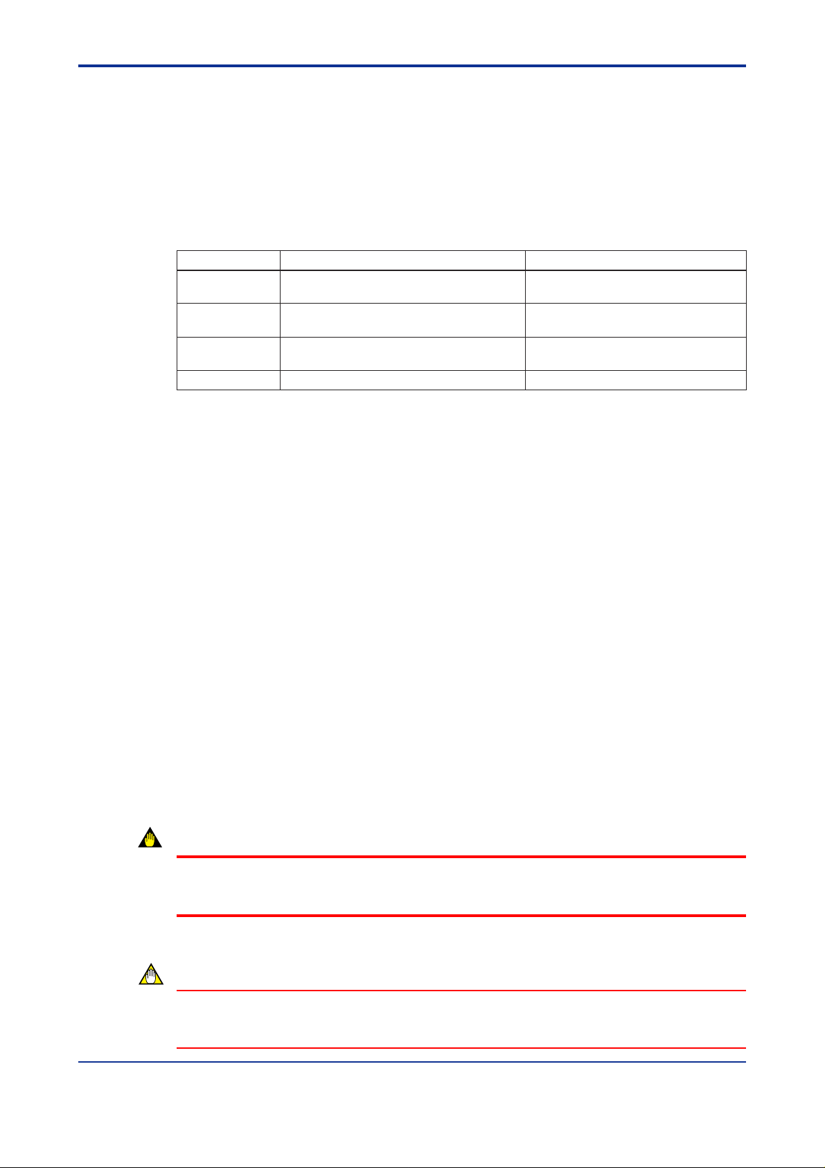
Table 1.1 List of User’ s Manual
IM No. Title
IM 01C25R01-01E EJX910A Multivariable Transmitter Hardware
Manual
IM 01C25R02-01E EJX910A HART Communication
IM 01C25R03-01E EJX910A Fieldbus Communication
IM 01C25R51-01E FSA120 EJX-MV Configuration DTM
In this manual, Following abbre viation ma y be used,
FF for FOUND ATION Fieldbus
Installation, wiring, and maintenance.
Operation manual for HART
communication type.
Operation manual for Foundation Fieldbus
communication type.
This manual. Operation manual of FSA120.
Contents
1-1
T0101E.EPS
1.1 About This Manual
• This manual should be delivered to the end user.
• The inf ormation contained in this manual is subject to change without prior notice.
• The inf ormation contained in this manual, in whole or part, shall not be transcribed or
copied without YOKOGA W A’s written permission.
• In no case does this manual guarantee the merchantability of the tr ansmitter or the
software or its adaptability to a specific client needs.
• If any question arises or errors are f ound, or if any inf ormation is missing from this
manual, please inform the nearest Y okoga wa sales office.
• Changes to specifications, structure, and components used ma y not lead to the re vision
of this manual unless such changes affect the function and perf ormance of the products.
• The operation of the EJX910DTM and EJXMVTool described in this manual is the
operation for the use with FieldMate Basic. For the detailed installation and operation of
FieldMate and additional functions availab le on FieldMate Advance , please ref er to the
FieldMate User’s man ual.
WARNING
Indicates a potentially hazardous situation which, if not avoided, could result in death or
serious injury.
CAUTION
Indicates a potentially hazardous situation which, if not avoided, ma y result in minor or
moderate injury . It ma y also be used to alert against unsafe practices .
All Rights Reserved Copyright © 2006, Yokogaw a Electric Corporation IM 01C25R51-01E
Page 7

<T oc> <Ind> <1. Introduction>
IMPORTANT
Indicates that operating the hardware or software in this manner ma y damage it or lead to
system failure.
NOTE
Draws attention to information essential f or understanding the operation and f eatures.
1.1.1 Trademarks
•Microsoft and Windows are trademarks or registered trademarks of Microsoft
Corporation in the US and other countries.
• Adobe, Adobe Acrobat, and Adobe Reader are tr ademarks or registered trademarks of
Adobe Systems Incorporated in the US and other countries.
1-2
•Pentium is a registered trademark of Intel Corporation.
• IBM PC/AT is a registered trademark of International Business Machines Corp.
• HAR T is a registered trademark of HART Comm unication F oundation.
•MACT ek is a registered tr ademark of MACTek Corporation.
• AIChE, DIPPR (Design Institute f or Ph ysical Properties) is a registered trademark of
American Institute of Chemical Engineers.
• NI-FBUS is a tr ademark of National Instruments Corporation.
• Other compan y/organization and/or product names are registered trade marks of their
respective holders.
• In this document, the TM and ® marks may not be sho wn ne xt to the registered
trademarks or trademarks of their respective companies.
1.1.2 Envir onmental Condition
Operation
Temperature: 0 to 40 °C
Humidity: 20 to 80 % (No de w condensation)
Storage
Temperature: -10 to 50 °C
Humidity: 20 to 80 % (No de w condensation)
All Rights Reserved Copyright © 2006, Yokogawa Electric Corporation IM 01C25R51-01E
Page 8

<Toc> <Ind> <1. Introduction>
1-3
1.2 Software License Agreement for EJXMVTool
License Agreement on EJX-MV Configuration DTM (EJXMVTool DTM) for Multivariable
Transmitter
IMPORTANT - PLEASE READ THIS AGREEMENT CAREFULLY :
BY INSTALLING, COPYING OTHERWISE USING THE ENCLOSED SOFTWARE PROD-
UCT AS IDENTIFIED ABOVE, YOU A GREE T O BE BOUND BY THE TERMS AND CONDITIONS OF THIS SOFTW ARE LICENSE A GREEMENT (“A GREEMENT”). IF YOU DO
NOT AGREE TO THE TERMS OF THIS A GREEMENT, DO NOT INSTALL, COPY OR USE
THE SOFTWARE PRODUCT AND PR OMPTLY RETURN IT T O THE PLACE OF PURCHASE.
1.2.1 Grant of License
(1) Subject to the terms and conditions of this Agreement, Yokogawa Electric Corporation
(“Licensor”) hereby grants to you (“Licensee”) a non-e xclusiv e and non-transf erab le
right to use the enclosed software product EJXMVTool as identified above and associated materials and documentation in printed or electronic format (Collectively “Licensed Software”), in consideration of full payment b y Licensee to the Licensor of the
license fee separately agreed upon by Licensor or its distrib utor .
(2) Licensee shall have the right to use the Licensed Software in the operating en viron-
ment identified by the Licensor , either (a) to the extent specified in the specifications
as agreed upon by both parties, or (b) if not specified, for a single user on single
computer.
TM
(3) Licensee may use the Licensed Software solely f or its own internal data processing
operations. Use of the Licensed Softw are for any purpose other than those as e xpressly specified in the documentation provided by Licensor shall be prohibited. An y
result or damage arising out of the use of licensed software shall be at Licensee’s o wn
risk and responsibility .
(4) No copies of the Licensed Software shall be made without Licensor’ s prior written
consent.
(5) The Licensed Software may contain software which Licensor is licensed from third
parties (“Third Party Software”). Licensee agrees to use the Third Party Software in
accordance with the terms and conditions as set forth by licensors of such Third P arty
Software and agrees to be bound thereby.
(6) In no event shall Licensee mak e any use of the Licensed Softw are for an y other
purposes or in any other manner than those stipulated hereunder.
(7) Licensee agrees to use any Third P arty Software solely as runtime use software which
shall be used solely as part of and with the integrated Licensed Software, and shall
not make any further use of Third P arty Software for any other purposes or in any
other manner.
1.2.2 Restriction
Licensee shall not: (a) remov e any marks or notices of the Licensed Softw are identification,
intellectual property rights like trademark and copyright notice, or other notices or restrictions from the Licensed Software; (b) tr ansfer, sell, assign, sublicense or otherwise convey
the Licensed Software to any third party without Licensor’s prior written consent; nor (c)
cause, permit or attempt the reverse engineering, disassembly, decompilation, translation
or adaptation of the Licensed Software. Any tr ansfer of the Licensed Softw are is subject to
Licensor’s transf er policies and f ees.
All Rights Reserved Copyright © 2006, Yokogawa Electric Corporation IM 01C25R51-01E
Page 9

<T oc> <Ind> <1. Introduction>
1.2.3 Copyright/Owner ship
The Licensed Software, including but not limited to an y technology, algorithm, know-how,
process and others contained therein, is the proprietary property and may include trade
secret of Licensor or a third party who grants to Licensor the right of sub-licensing and is
protected by copyright and other intellectual property laws and treaties. Licensee acquires
only right to use the Licensed Software and does not acquire any rights, expressed or
implied, in the Licensed Software or media containing the Licensed Software other than
those specified in this Agreement. Licensor shall at all times retain all rights, titles, and
interests, including intellectual property rights, in the Licensed Software and such media.
The Licensee may not disclose or divulge the af oresaid trade secret to any other individual
or entity than the Licensee's personnel who reasonably need to know and the Licensee.
1.2.4 No W arranty / Limitation of Liability
(1) THE LICENSED SOFTWARE SHALL BE PR O VIDED TO LICENSEE ON AN "AS IS"
BASIS. UNLESS O THER WISE EXPRESSLY PRO VIDED BY LICENSOR, LICENSOR AND THE SUPPLIERS WHO PROVIDE OR LICENSE PART OF THE LICENSED SOFTW ARE T O LICENSOR ("SUPPLIERS") HEREBY EXPRESSLY
DISCLAIM ANY AND ALL IMPLIED WARRANTIES OF ANY KIND WHA TSOEVER,
INCLUDING WITHOUT LIMITATION W ARRANTY OF UNINTERR UPTED OR ERROR-FREE OPERATION, SATISFACT OR Y Q U ALITY, NON-INFRINGEMENT, MERCHANTABILITY OR FITNESS FOR A P ARTICULAR PURPOSE, AND SHALL NOT
BE LIABLE TO LICENSEE FOR ANY DAMA GE OR LOSS CA USED BY USE OR
INABILITY TO USE OF THE LICENSED SOFTW ARE. LICENSOR AND SUPPLIERS
DISCLAIM ANY AND ALL LIABILITY AND WILL HAVE NO LIABILITY FOR VIOLATION, MISAPPROPRIATION OR INFRINGEMENT OF INTELLECTUAL PROPER TY
RIGHTS OF ANY THIRD PARTY.
1-4
(2) IN NO EVENT SHALL LICENSOR AND SUPPLIERS BE LIABLE, WHETHER IN
CONTRACT, T ORT OR O THER WISE AND WHETHER OR NOT LICENSOR AND
SUPPLIERS HA VE BEEN AD VISED OF THE POSSIBILITY OF SUCH LOSS OR
DAMAGE, FOR ANY LOSS OR DAMAGE INCLUDING CONSEQUENTIAL, INCIDENTAL, INDIRECT OR EXEMPLARY DAMA GES, LOSS OF PR OFITS , LOSS OF
REVENUE, LOSS OF BUSINESS OR GOODWILL, LOSS OF DATA OR LOSS OF
AVAILABILITY.
(3) THIS SECTION 1.2.4 STA TES THE ENTIRE WARRANTY AND LIABILITY OF LI-
CENSOR AND SUPPLIERS IN CONNECTION WITH THE LICENSED SOFTWARE.
THIS PARAGRAPH 4 ALLOCATES RISKS UNDER THIS A GREEMENT BETWEEN
LICENSEE AND LICENSOR/SUPPLIERS AND COMPRISES FUNDAMENTAL
ELEMENTS OF THIS LICENSE. LICENSOR’S PRICING OF THE LICENSED SOFTWARE REFLECTS THIS ALLOCATION OF RISKS AND LIMIT ATION OF LIABILITY.
(4) LICENSEE SHALL INDEMNIFY, DEFEND AND HOLD LICENSOR AND SUPPLIERS
FROM ANY CLAIMS, DEMANDS , LIABILITIES, LOSSES , D AMA GES, JUDGMENTS
OR SETTLEMENTS, INCLUDING ALL REASONABLE COSTS AND EXPENSES
RELATED THERETO INCLUDING ATTORNEY’S FEES, DIRECTLY OR INDIRECTLY
RESULTING FROM ANY CLAIM MADE OR PO TENTIAL CLAIM BY A THIRD PARTY
AGAINST LICENSOR OR SUPPLIERS ARISING OUT OF ANY A CT OR USE OF
LICENSED SOFTWARE BY LICENSEE.
1.2.5 T erm and T ermination
(1) This Agreement shall become effectiv e when the Licensee installs, copies or other-
wise uses the Licensed Software and remain in full force until and terminate when (a)
Licensor terminates this Agreement according to this 1.2.5 (2); or (b) the Licensee
ceases to use the Licensed Product, whichever comes earlier.
(2) Licensor shall have the right to immediately terminate this Agreement without any
notice to Licensee, if Licensee breaches any of the terms and conditions hereof.
All Rights Reserved Copyright © 2006, Yokogawa Electric Corporation IM 01C25R51-01E
Page 10

<Toc> <Ind> <1. Introduction>
(3) Upon termination of this Agreement, Licensee shall immediately , in accordance with
instructions by Licensor, return all copies of the Licensed Software in its possession to
Licensor or its designee and erase all copies of the Licensed Software installed in any
computer hereunder.
(4) The license fee paid by the Licensee to the Licensor in consideration of the use of the
Licensed Software hereunder shall be non-refundable unless otherwise e xpressly
provided herein.
(5) The provisions of the 1.2.3 and 6 shall survive after termination of this Agreement.
1.2.6 General Provisions
(1) This Agreement shall be governed by and construed in accordance with the laws of
Japan. All disputes , controv ersies or differences which ma y arise between the parties
hereto, out of or in relation to or in connection with this Agreement shall be finally
settled by arbitration in Tokyo, Japan in accordance with the Commercial Arbitr ation
Rules of the Japan Commercial Arbitration Association. The award rendered by the
arbitrator(s) shall be final and binding upon the parties hereto.
(2) This Agreement shall supersede any prior representations, discussions, undertakings,
communications or advertising with respect to the Licensed Software.
(3) If any part of this Agreement is found void or unenf orceab le under any la ws or regula-
tions and Licensor deems it is not reasonable to license without such void or unenforceable part, Licensor is entitled to modify the terms of this Agreement or terminate
this Agreement at its option without owing any liability to Licensee.
(4) Licensee agrees that the Licensed Software shall not be shipped, transf erred or
exported to any country or used in any manner prohibited by any e xport administration
laws, restrictions or regulations or regulations of Japan, the United States and other
countries that may be applicable to the Licenced Software.
1-5
1.2.7 DIPPR
(1) Licensed Software may include a database dev eloped by the Design Insti-
(2) THE BYU-TPL WILL USE REASONABLE EFFORTS DESIGNED T O
(3) LICENSEE ACKNOWLEDGES THE ABO VE 1.2.7 (1) AND (2) AND
tute for Ph ysical Property Data (DIPPR®) which is a branch of the sponsored
research projects of the American Institute of Chemical Engineers (AIChE®).
VERIFY THAT THE D ATA CONT AINED IN THE D ATABASE HAS BEEN
SELECTED ON THE BASIS OF SOUND SCIENTIFIC JUDGMENT. HO W EVER, NEITHER THE BYU-TPL NOR AICHE® MAKE ANY W ARRANTIES
TO THAT EFFECT. THE D ATABASE IS PRO VIDED “AS IS” WITHOUT
WARRANTY OF ANY KIND. BYU-TPL DISCLAIMS ALL W ARRANTIES ,
EITHER EXPRESS OR IMPLIED , INCLUDING BUT NO T LIMITED T O
WARRANTIES OF MERCHANT ABILITY AND FITNESS FOR A PARTICULAR PURPOSE. NEITHER THE BYU-TPL NOR AICHE® SHALL BE LIABLE FOR ANY DAMA GES , LOSS OF PROPER TY OR PROFITS, OR
CONSEQUENTIAL, EXEMPLARY OR SPECIAL DAMAGES THAT MAY
RESULT FROM ERRORS OR OMISSIONS IN THE D ATABASE EVEN IF
AD VISED OF THE POSSIBILITY OF SUCH D AMA GES.
AGREES NO T TO MAKE ANY CLAIMS OR DEMANDS AGAINST LICENSOR, BYU-TPL NOR AICHE® WITH RESPECT TO DIPPR® AS STATED IN
1.2.4 (4).
All Rights Reserved Copyright © 2006, Yokogawa Electric Corporation IM 01C25R51-01E
Page 11

Blank Page
Page 12
<Toc> <Ind> <2. General >
2. General
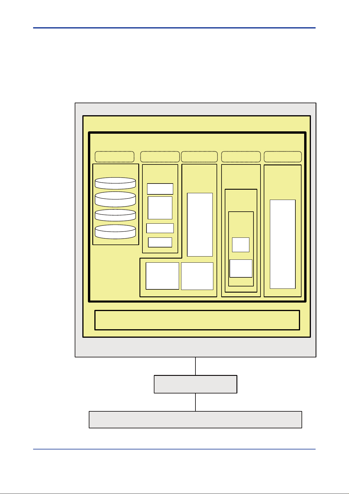
EJXMVTool is a PC tool that is used to set the flow parameters of EJX910A multivariable
transmitters.
EJXMVTool consists of Flow Configuration Wizard and Obtain Flow Coefficient.
The following chart shows a configuration consisting of a note PC, communication interf ace
and EJX910A multivariable transmitter .
Frame Application
EJX-MV Configuration DTM
2-1
EJXMVTool DTM
This area requires license
Database
Operating conditions
Primary element
information
Fluid information
Phisical property
database
EJXMVTool DTM
This area requires license
Flow
Configuration
Wizard
Dialog editor
Calculation
of flow
parameters
for EJX910
File
Management
Report
Upload
from
transmitter
Comm DTM
EJX910 HART DTM
EJX910 FF DTM
Transmitter
Management
(Offline
parameters)
Dialog
Editor
Monitoring
Process
Value
Tag
Range
Unit
Damping
Lowcut
Adjustment
Download
to
transmitter
EJXMVTool DTM
This area requires license
Flow
Parameter
Management
Obtain Flow
Coefficient
Dialog
Editor
Sensor
mode
Simulation
mode
EJX910 HART DTM
EJX910 FF DTM
Transmitter
Management
(Online
parameters)
Dialog
Editor
Monitoring
Process
Value
Tag
Range
Unit
Damping
Lowcut
Adjustment
Notebook PC
PCMCIA I/F / Serial Port
FF-H1 /HART Communications
NI PCMCIA F-BUS
/HART modem
FF-H1 /HART Communications
Multivariable Transmitter
(EJX910A)
F0201.EPS
Figure 2.1 Functional diagram
All Rights Reserved Copyright © 2006, Yokogawa Electric Corporation IM 01C25R51-01E
Page 13

Blank Page
Page 14

<Toc> <Ind> <3. Function Specification>
3. Functional Specification
3.1 PC
3.1.1 Hardware Operating En vir onment
Condition for the FieldMate is included.
Machine: IBM PC/AT-compatible
CPU: P entium3 1 GHz or faster
Main memory: 1 GB or more
Hard disk drive: 8 GB or more
CD-ROM drive: Windows XP compatib le
Display: 1024 768 or better resolution recommended 16 bit colors or better
For HART comm unication: Serial port (RS232C or USB)
OUNDATION Fieldbus communication: Either PCMCIA card slot or PCI slot
For F
3-1
3.1.2 Software Operating Envir onment
IMPORTANT
When using FOUNDATION Fieldbus DTM, login Windo ws as an Administrator or a user with
an administrative authority.
Microsoft Windows XP Prof essional SP2 (English)
Following software is necessary to be installed in your computer .
Common
Adobe Reader
FDT Frame application conf orming to FDT Interface Specification Version 1.2
The frame application which is already tested with FSA120 and proper operation is
confirmed; FieldMate
For HART Communication
Communication DTM for HAR T Modem conformed FDT Interf ace Specification Version 1.2
Follo wing Communication DTM has been tested with FSA120 and compatibility is
confirmed; HART Comm unication DTM included in FieldMate
OUNDATION Fieldbus Comm unication
For F
(included in FieldMate)
NI-FBUS Communications Manager
Communication DTM for PCMCIA-FBUS or PCI-FB US conf orming to FDT version 1.2
Follo wing Communication DTM has been tested with FSA120 and compatibility is
confirmed; F
All Rights Reserved Copyright © 2006, Yokogawa Electric Corporation IM 01C25R51-01E
OUNDATION Fieldbus communication DTM included in FieldMate.
Page 15
<T oc> <Ind> <3. Function Specification>
NOTE
Install the following software which is contained in CD if y ou don’t hav e them in y our computer. Refer to section 4.2 for procedures.
1)Adobe Reader
2)FieldMate
• FDT Frame application
• HART communication DTM
• FF communication DTM
3)Device Files
• FJX910 HART DTM (included in Yokogawa DTM Library HART)
• FJX910 FF DTM (included in Yokogawa DTM Libr ary FF)
IMPORTANT
3-2
If you already hav e FSA210 Mass Flow Configuration Softw are installed in your computer,
Uninstall FSA210 to avoid the competition of COM POR T.
3.2 Field Communication
1)HART communication
Recommended HART modem: USB HART Interf ace (Yokogawa P arts Number F9197UB)
OUNDATION Fieldbus communication
2)F
Recommended: NI-FBUS:National Instrument’ s PCMCIA-FB US or PCI-FBUS NI-FBUS
3.0 or later
3.3 Model to be Connected
EJX910A Multivariable Transmitter
All Rights Reserved Copyright © 2006, Yokogawa Electric Corporation IM 01C25R51-01E
Page 16

<Toc> <Ind> <3. Function Specification>
3.4 Outline of FSA120
3.4.1 Components
Following picture sho ws the items included in the FSA120 package.
3-3
Disk
FieldMate
Disk
Yokogawa
EJXMVTool
additional
resource
Figure 3.1 Components of FSA120
User license
sheet
(FieldMate)
User license
sheet
(EJXMVTool)
F0301E.EPS
Disk
Device Files
Each disk contains the following software.
[FieldMate disk]
•FieldMate
[Device Files disk]
•Yokogawa DTM Library HART
(Includes EJX910 HART DTM, EJXMVTool source program and HART DTMs of other
YOKOGAW A products.)
•Yokogawa DTM Libr ary FF
(Includes EJX910 FF DTM, EJXMVTool source program and FF DTMs of other
YOKOGAW A products.)
[Yokogawa MVTool additional resource disk]
• Programs necessary to activate EJXMVTool
• User's manual of EJXMVTool (in pdf format)
FieldMate is Yokogawa's FDT fr ame application and bundled in FSA120. Device Files
contains YOKOGA W A DTM library which include EJX910 HART/FF DTM(f or transmitter
management) and EJXMVTool DTM (for flow parameter management).
Yokogawa MVTool additional resource disk contains the programs necessary for
EJXMVTool.
To use the full part of FSA120, it is necessary to correctly install a frame application
(FieldMate), libraries, and the programs in the additional resource disk into your computer .
All Rights Reserved Copyright © 2006, Yokogawa Electric Corporation IM 01C25R51-01E
Page 17

<T oc> <Ind> <3. Function Specification>
3.4.2 EJX910 HART/FF DTM and EJXMVTool
EJX910 HART/FF DTM and EJXMVTool consist of the following programs.
Table 3.1 Function of EJXMVT ool (f or HART comm unication)
Program Function
EJX910HART DTM
EJX
MVTool
Flow
Configuration
Wizard
Obtain Flow
Coefficient
Database
Transmitter
Management
Flow
Parameter
Management
Flow
Parameter
Management
Database - Necessary* Physical property
* Online Parameter
* Offline Parameter
* Downloads to or uploads
from the transmitter
parameters for the
EJX910A.(Auto
compensation mode,
Basic mode)
* File management
* Report function
retrieval
database used for flow
parameter calculation.
<DTMInstDrive>
\Program
Files\Yokogawa
\DTMs
<DTMInstDrive>
\Program
Files\Yokogawa
\DTMs
\EJXMVTool
Startup method
Execute from
the frame
application
Execute from
the EJX910
HART DTM
Execute from
the EJX910
HART DTM
3-4
Entry of LicenseContens Install location
Not
necessary
Necessary* Configuration of flow
Necessary* Flow coefficient
T0301-1E.EPS
Table 3.2 Function of EJXMVT ool (f or FF comm unication)
Program Function
EJX910FF DTM
EJX
MVTool
Flow
Configuration
Wizard
Obtain Flow
Coefficient
Database
Transmitter
Management
Flow
Parameter
Management
Flow
Parameter
Management
Database - Necessary* Physical property
* Online Parameter
* Offline Parameter
* Downloads to or uploads
from the transmitter
parameters for the
EJX910A. (Auto
compensation mode,
Basic mode)
* File management
* Report function
retrieval
database used for flow
parameter calculation.
<DTMInstDrive>
\Program
Files\Yokogawa
\DTMs
<DTMInstDrive>
\Program
Files\Yokogawa
\DTMs\EJXMVTo
olFF
Startup method
Execute from
the frame
application
Execute from
the EJX910
FF DTM
Execute from
the EJX910
FF DTM
Entry of LicenseContens Install location
Not
necessary
Necessary* Configuration of flow
Necessary* Flow coefficient
T0301-2E.EPS
Each program can be started in the following wa y.
>Execute EJX910 HART DTM or EJX910 FF DTM on the frame application.
(Not necessary to enter a license for EJXMVTool)
>Execute the Flow Configuration Wizard /Obtain Flo w Coefficient on the EJX910 HAR T or
FF DTM (Necessary to enter your license for EJXMVTool.)
All Rights Reserved Copyright © 2006, Yokogawa Electric Corporation IM 01C25R51-01E
Page 18
<Toc> <Ind> <3. Function Specification>
3.5 FSA120 DTM Function Detail
3.5.1 T ransmitter Mana gement
Transmitter management function is supported by EJX910 HART DTM and EJX910 FF
DTM.
EJX910FF DTM supports the following blocks in the EJX910: Resource Block, Sensor
Transducer Block, Flow Transducer Block, LCD Transducer bloc k, and AI function blocks .
Parameters of other function blocks should be set and changed by other Fieldbus
configurators.
• Setting of Node Address and tag is not supported.
• Scheduling is not supported.
NOTE
Setting of Node Address and PD Tag and scheduling are not supported by FSA120. Use
general purpose Fieldbus setting tool to set these items. After using setting tool, finish the
program before starting FSA120.
3-5
(1) Online Parameter
The Transmitter General parameters of the device can be edited directly in online
status.
(Process value monitoring, Tag, Range, Unit, Damping, Lowcut, Indicator displa y,
Maintenance, Adjustment, Status information display)
(2) Offline Parameter
The Transmitter General parameters of the device can be edited and stored in offline
database.
(Process value monitoring, Tag, Range, Unit, Damping, Lowcut, Indicator displa y,
Maintenance, Adjustment, Status information display)
(3) Downloads to or uploads from the transmitter
The Transmitter Flow and General P arameters stored in offline database are
downloaded the to device .
The parameters of the device is uploaded from the de vice and stored in offline
database.
Transmitter General Parameters:
HART or F
HART handheld terminal or Fieldbus Configuration Tool. e.g. range, damping, etc.
User Flow Parameters:
The parameters which users input on EJXMVTool for flow configuration.
OUNDATION Fieldbus parameters of the de vice, which can be modified with using
This parameters are used to generate flow appro ximation and not downloaded to the
device.
Transmitter Flow Parameters:
The parameters which EJXMVTool calculates and generates with using the User Flow
Parameters and are downloaded to the device.
All Rights Reserved Copyright © 2006, Yokogawa Electric Corporation IM 01C25R51-01E
Page 19

<T oc> <Ind> <3. Function Specification>
3.5.2 Flow P arameter Management (Flow Configuration Wizard)
This function is supported by EJXMVTool DTM.
(1) Auto compensation mode
Configuration of the fluid physical properties and primary element for the EJX910A
can be performed using a dialog window . Refer to section 6.3.
(2) Basic mode
Flow operation and density compensation are perf ormed conventionally, with the flow
factors being input manually. Ref er to section 6.4.
(3) File management
xmv file: Import / export User Flow parameters
Import / export Transmitter Flow parameters.
prm file: Import HART Transmitter General parameters
(only for FSA210 user)
(4) Report function
Export user flow parameters in CSV file format.
3.5.3 Flow P arameter Management (Obtain Flow Coefficient)
3-6
This function is supported by EJXMVTool.
Flow coefficient retrieval
The flow coefficient can be obtained from the transmitter (input selection: sensor data
or simulated data).
All Rights Reserved Copyright © 2006, Yokogawa Electric Corporation IM 01C25R51-01E
Page 20

<Toc> <Ind> <3. Function Specification>
3.5.4 Primary Devices Supported in Auto Compensation Mode
This function is supported by EJXMVT ool DTM.
Table 3.3 Supported primary devices
Type
Orifice
Nozzle
Venturi
FIX
Orifice Corner Taps [ISO5167-1 1991]
Orifice Corner Taps [ISO5167-2 2003]
Orifice Corner Taps [ASME MFC-3M 1989]
Orifice Flange Taps [ISO5167-1 1991]
Orifice Flange Taps [ISO5167-2 2003]
Orifice Flange Taps [ASME MFC-3M 1989]
Orifice Flange Taps [AGA No.3 1992]
Orifice D and D/2 Taps [ISO5167-1 1991]
Orifice D and D/2 Taps [ISO5167-2 2003]
Orifice D and D/2 Taps [ASME MFC-3M 1989]
ISA1932 nozzle [ISO5167-1 1991/ ISO5167-3 2003]
Long radius nozzle [ISO5167-1 1991/ ISO5167-3 2003]
ASME FLOW NOZZLES [ASME MFC-3M 1989]
Venturi nozzle [ISO5167-1 1991/ ISO5167-3 2003]
Classical Venturi tube “as cast” convergent section [ISO5167-1 1991/ ISO5167-4 2003]
ASME Venturi Tubes With a rough Cast or Fabricated Convergent [ASME MFC-3M 1989]
Classical Venturi tube with a machined convergent section [ISO5167-1 1991/ ISO5167-4 2003]
ASME Venturi Tubes With a machined convergent section [ASME MFC-3M 1989]
Classical Venturi tube with a rough-welded sheet-iron convergent section
[ISO5167-1 1991/ ISO5167-4 2003]
Fixed Mode (Sets the discharge coefficient and gas expansion factor to a fixed value)
Primary Device
T0302E.EPS
3-7
All Rights Reserved Copyright © 2006, Yokogawa Electric Corporation IM 01C25R51-01E
Page 21
<T oc> <Ind> <3. Function Specification>
3.5.5 Density Compensation in Auto Compensation Mode
This function is supported by EJXMVTool DTM.
(1) Density compensation using physical properties database
Table 3.4 Supported physical properties database
Fluid name Fluid name Fluid name
Acetic Acid Hydrogen Chloride Phosphoric Acid
Acetone Hydrogen Cyanide Propadiene
Acetonitrile Hydrogen Peroxide Propane
Acetylene Hydrogen Sulfide Propylene
Acrylonitrile Isobutane Pyrene
Air Isobutene Styrene
Allyl Alcohol Isobutylbenzene Sulfur Dioxide
Ammonia Isopentane Toluene
Argon Isoprene Trichloroethylene
Benzaldehyde Isopropanol Trichlorofluoromethane
Benzene m-chloronitrobenzene Vinyl Acetate
Benzoic Acid m-dichlorobenzene Vinyl Chloride
Benz Alcohol Methane Vinyl Cyclohexene
Biphenyl Methanol Water
Bromine Methyl Acrylate 1-Butene
Carbon Dioxide Methyl Ethyl Ketone 1-Decene
Carbon Monoxide Methyl Vinyl ether 1-Decanal
Carbon Tetrachloride Monochlorobenzene 1-Decanol
Chlorine n-Butane 1-Dodecene
Chlorodifluoromethane n-Butanol 1-Dodecanol
Chloroprene n-Butyraldehyde 1-Heptanol
Chlorotrifluoroethylene n-Butyronitrile 1-Heptene
Citric Acid n-Decane 1-Hexene
Cycloheptane n-Dodecane 1-Hexadecanol
Cyclohexane n-Heptadecane 1-Octanol
Cyclopentane n-Heptane 1-Octene
Cyclopentene n-Hexane 1-Nonanal
Cyclopropane n-nonane 1-Nonanol
Dichlorodifluoromethane n-Octane 1-Pentadecanol
Divinyl Ether n-Pentane 1-Pentanol
Ethane Neon 1-Pentene
Ethanol Neopentane 1-Undecanol
Ethylamine Nitric Acid 1,1,2,2-Tetrafluoroethane
Ethylbenzene Nitric Oxide 1,1,2-Trichloroethane
Ethylene Nitrobenzene 1,2,4-Trichlorobenzene
Ethylene Glycol Nitroethane 1,2-Butadiene
Ethylene Oxide Nitrogen 1,3-Butadiene
Fluorene Nitromethane 1,3,5-Trichlorobenzene
Furan Nitrous Oxide 1,4-Dioxane
Helium-4 Oxygen 1,4-Hexadiene
Hydrazine Pentafluoroethane 2-Methyl-1-Pentene
Hydrogen Phenol
Source:
DIPPR
This Physical Property Database from American Institute of Chemical Engineers
(AIChE
®
Project No .801 Database 2003 Edition
®
)
2,2-Dimethylbutane
3-8
T0303E.EPS
All Rights Reserved Copyright © 2006, Yokogawa Electric Corporation IM 01C25R51-01E
Page 22

<Toc> <Ind> <3. Function Specification>
NOTE
The DIPPR recommends an air temperature no higher than –25°C and cannot guarantee results if this temperature limit is exceeded.
(2) Density compensation using standard steam tables
IAPWS-IF97 W ater and Steam (1997)
IAPWS-IF97: IAPWS Industrial F ormulation 1997
IAPWS: The International Association for the Properties of W ater and Steam
(3) Density compensation using standard.
Natural gas:
AGA8.
Compressibility Factors of Natural Gas and Other Related Hydrocarbon Gases
American Gas Association (AGA)
Transmission Measurement Committee Report No.8 Second Edition, Nov ember
1992
3-9
Detail Characterization Method
Gross Characterization Method 1
Gross Characterization Method 2
ISO 12213:1997 First edition 1997-12-01
Part 2: molar-composition analysis
Part 3: ph ysical properties
(4) Custom fluid density and viscosity compensation
Numerical value user input for physical properties (density, viscosity, etc.)
All Rights Reserved Copyright © 2006, Yokogawa Electric Corporation IM 01C25R51-01E
Page 23

Blank Page
Page 24
<Toc> <Ind> <4. Preparation>
4. Preparation
4.1 PC
To ensure that EJXMVTool functions properly, please make sure your PC meets the
requirements stated in the section ‘3.1 PC’.
All application must be finished.
4.1.1 Setting Items after Installing Windo ws
Before installing EJXMVTool to Windows environment, the f ollo wing settings are recommended.
•Power Options
It is recommended to set System Standby to [Nev er]. Setting procedure is as f ollows .
Login Windows XP as administrator , and then choose [Start] - [Control P anel] [PowerOptions] to open [Power Options Properties] dialog box. Confirm the settings on this
dialog box are the same as follows .
4-1
•Power Schemes Tab
System standby and System hibernates are recommended to be set as follows;
Turn off hard disk: Nev er
System standby: Ne v er
System hibernates: Nev er
Power Options Properties
HibernateAdvancedPower Schemes
Select the power scheme with the most apropriate settings for
this computer. Note that changing the settings below will modify
the selected scheme.
Power schemes
Home/Office Desk
Setting for Home/Office Desk power scheme
NeverTurn off monitor:
NeverTurn off hard disks:
NeverSystem standby:
NeverSystem hibernates:
UPS
DeleteSave As...
CancelOK
Figure 4.1 Power Sc hemes Tab
All Rights Reserved Copyright © 2006, Yokogawa Electric Corporation IM 01C25R51-01E
Apply
F0401E.EPS
Page 25
<T oc> <Ind> <4. Preparation>
• Adv anced T ab
Some PC keyboards hav e a sleep b utton. It is recommended to disab le this b utton.
When press the sleep button on my computer: No action
Figure 4.2 Advanced T ab
• Hibernate T ab
Do not check the option [Enable hibernation].
Power Options Properties
4-2
HibernateAdvancedPower Schemes
When you computer hibernates, it stores whatever it has in
memory on your hard disk and then shuts down. When your
computer comes out of hibernation, it returns its previous state.
Hibernate
Enable hibernation
Disk space for hibernation
Free disk space: 22,057 MB
Disk space required to hibernate: 256 MB
Figure 4.3 Hibernate Tab
UPS
CancelOK
Apply
F0403E.EPS
All Rights Reserved Copyright © 2006, Yokogawa Electric Corporation IM 01C25R51-01E
Page 26

<Toc> <Ind> <4. Preparation>
4.2 Installation Procedure
4.2.1 EJXMVT ool online man ual
The pdf format Manual for EJXMVTool is located at <Yokogawa MVTool Additional resource
disk>: \EJXMVTool_Manual.pdf.
If Adobe Reader is not on your PC, install it.
This may be done by doub le clicking on < FieldMate CDROM>:
\READER\ENGLISH\AdbeRdr80_en_US.ex e in Windo ws Explorer.
(<CDROM> is the CD-ROM drive of your computer.)
4.2.2 Uninstall FSA210
This procedures are only applicable for the users of FSA210 Mass Flow Configur ation
Software.
If FSA210 is existing on your PC , uninstall it to av oid the competition with FieldMate.
To uninstall all the program of FSA210, take the following three steps.
(1) Uninstall a field communication server
Execute <FieldInstDrive>: \PRM\Prog ram\PRMUninstall.e x e
4-3
Double-click the filename in Windows Explorer .
<FieldInstDrive> is the drive on which field communication server is installed.
<FieldInstDrive> is the drive where the PRM directory is located.
The default drive is the same drive on which Windo ws is installed.
(2) Uninstall the EJXMVTool program with the Add or Remove Programs function of the
Windows Control Panel. Select EJXMVT ool and click [Change/Remov e].
(3) Uninstall Exaopc
Use the Add or Remove Progr ams function of the Windows Control P anel to uninstall
Exaopc. Select Exaopc and clic k [Change/Remov e].
Follow the instruction to reboot the computer .
NOTE
Refer to Appendix A for the detailed procedures of uninstalling FSA210.
4.2.3 For FieldMate Users
If you already hav e FieldMate installed in your computer , which satisfies the oper ating
requirement of FSA120, you may need to skip the installation of FieldMate. Please see the
followings.
NOTE
If FieldMate installed in your PC is older version and does not satisfy the working condition
of FSA120, it is necessary to install FieldMate which satisfies the requirement.
All Rights Reserved Copyright © 2006, Yokogawa Electric Corporation IM 01C25R51-01E
Page 27

<T oc> <Ind> <4. Preparation>
1)If you have FieldMate Basic installed on your PC , and...
• if y ou ha ve purchased FSA120 with FieldMate Basic;
check the version of FieldMate which is installed on y our PC .
On the other hand, the version of the bundled FieldMate is sho wn on the disk.
If the version is low er than that of the bundled FieldMate , install the bundled
FIeldMate.
If the version is equiv alent or higher , install Additional Resource Disk alone.
• if y ou ha ve purchased FSA120 with FieldMate Adv ance;
install the bundled FieldMate Advance and Additional Resource Disk.
2)If you have FieldMate Advance installed on y our PC, and...
• if y ou ha ve purchased FSA120 with FieldMate Basic;
check the version of FieldMate which is installed on y our PC .
On the other hand, the version of the bundled Fieldmate is sho wn on the disk.
If the version is low er than that oh the bundled FieldMate, install the b undled
FieldMate Basic after uninstalling the previous v ersion of FieldMate Advance .
If the version is equiv alent or higher , install Additional Resource Disk alone.
4-4
• if y ou ha ve purchased FSA120 with FieldMate Adv ance;
check the version of FieldMate which is installed on y our PC .
On the other hand, the version of the bundled FieldMate is sho wn on the disk.
If the version is low er than that of the bundled FieldMate , install the bundled
FIeldMate.
if the version is equivalent or higher, install Additional Resource Disk alone.
4.2.4 Installations of FieldMate and Device Files
For the installations of FieldMate and De vice Files, please f ollow the procedures described
in the User’s manual “FieldMate Versatile Device Management Wizard Getting Started” (IM
01R01A04-01E) included in the FSA120 package.
•Yokogawa HART/FF DTM library
Automatically installed during the installation of FieldMate.
• Related program installation(f or F
For the operation of EJX910 FF DTM, "NI-FBUS Comm unications Manager" must be
installed.
NOTE
OUNDATION Fieldbus communication)
For the installation procedures of FieldMate, ref er to the user’ s man ual of FieldMate.
When installing FieldMate, log-in the Windo ws as an Administrator or an user with an
administrative authority.
All Rights Reserved Copyright © 2006, Yokogawa Electric Corporation IM 01C25R51-01E
Page 28
<Toc> <Ind> <4. Preparation>
4.2.5 EJX MVT ool additional resour ce installation
Execute <CDROM>: \ Resource \ setup .e x e
Double-click the file name in Windows Explorer, and the EJXMVTool installation prog ram
will be started.
(<CDROM> is the CD-ROM drive of your computer.)
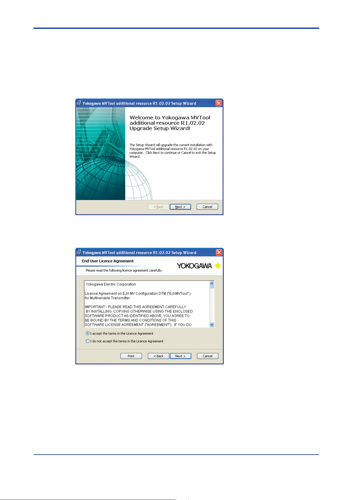
(1) Click [Next].
4-5
Figure 4.6a W elcome screen
(2) Select [I accept ...] and click [Next].
Figure 4.6b License agreement screen
F0405E.EPS
F0406E.EPS
All Rights Reserved Copyright © 2006, Yokogawa Electric Corporation IM 01C25R51-01E
Page 29
<T oc> <Ind> <4. Preparation>
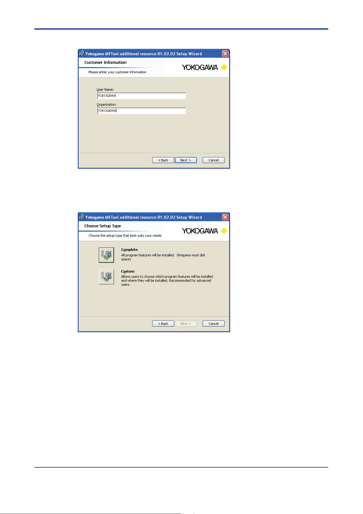
(3) Input “User Name”,“Organization” and Clic k [Next].
F0407E.EPS
Figure 4.6c Customer Information Screen
(4) Select [Complete] or [Custom].
4-6
Complete setup is recommended.
Figure 4.6d Choose Setup Type
F0408E.EPS
All Rights Reserved Copyright © 2006, Yokogawa Electric Corporation IM 01C25R51-01E
Page 30
<Toc> <Ind> <4. Preparation>
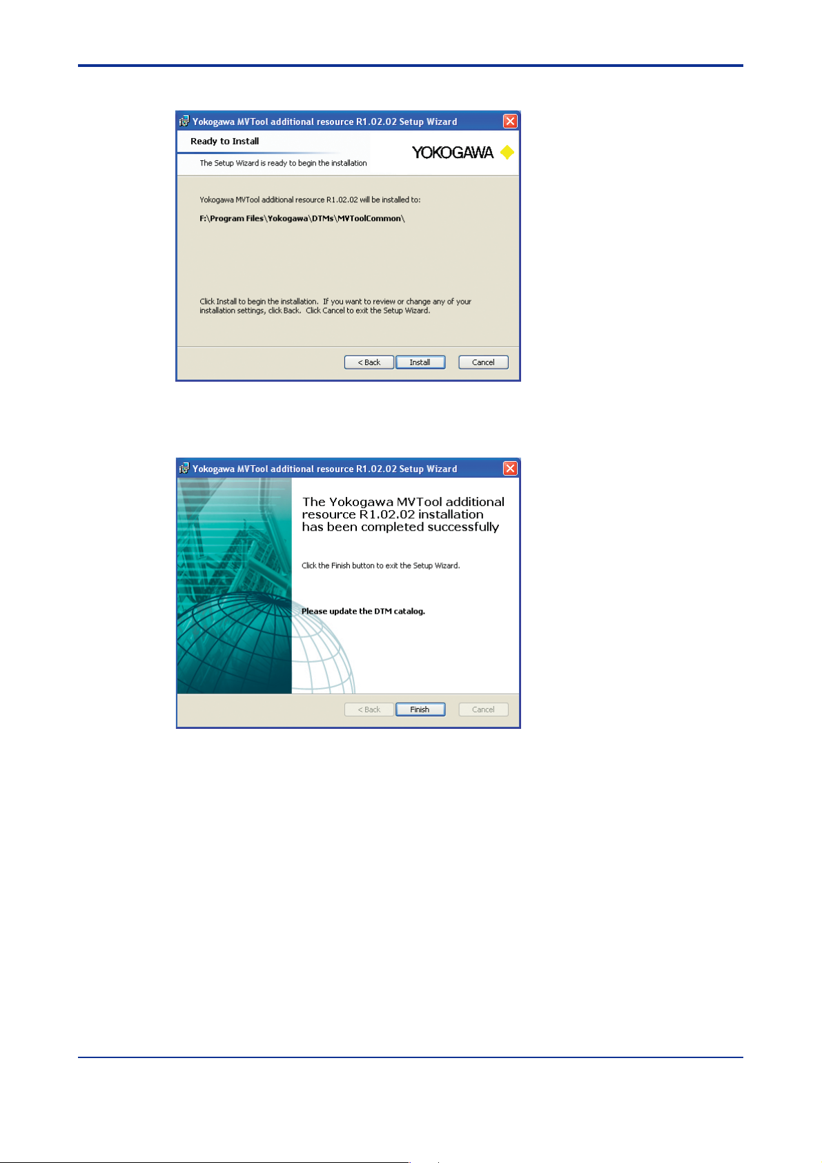
(5) Click [Install].
F0409E.EPS
Figure 4.6e Ready to install screen
(6) Click [Finish].
4-7
F0410E.EPS
Figure 4.6f Finish Setup screen
All Rights Reserved Copyright © 2006, Yokogawa Electric Corporation IM 01C25R51-01E
Page 31

<T oc> <Ind> <4. Preparation>
4.2.6 How to confirm V ersion Number of DTM
1)Y ok oga wa HAR T/ FF DTM library
The version number is display ed on the “Add / remov e program” screen of Windo ws
Control Panel. (See figure 4.7.)
Version number
F0411E.EPS
Figure 4.7 V ersion Number of DTM Library
4-8
2)EJXMVT ool DTM
The version number is display ed on the HELP screen of Flow Configur ation Wizard or
Obtain Flow Coefficient.
Refer to 6.2.5 or 6.5.
3)MVT ool additional resource (Release number of FSA120)
The version number is display ed on the “Add / remov e program” screen of Windo ws
Control Panel. (See figure 4.8.)
4) EJX910DTM
Refer to 4.6.3 ‘Start EJX910DTM’.
F0412E.EPS
Figure 4.8 V ersion No. of Y okoga wa MVTool Addirional Resource
All Rights Reserved Copyright © 2006, Yokogawa Electric Corporation IM 01C25R51-01E
Page 32

<Toc> <Ind> <4. Preparation>
4.3 Uninstallation
(1) FieldMate
Refer to User's manual IM01R01A01-00E.
(2) MVTool Additional Resouce
Use the Add or Remove Progr ams function of the Windows Control P anel.
Select Yokoga wa MVTool additional resouce Rx.xx.xx and click [Remove].
4-9
Figure 4.9 Remove Yokoga wa MVTool Additional Resource
F0413E.EPS
All Rights Reserved Copyright © 2006, Yokogawa Electric Corporation IM 01C25R51-01E
Page 33

<T oc> <Ind> <4. Preparation>
4.4 Initial Setting (HART comm unication)
4.4.1 HART Communication Modem
Connect the HART communication modem to the PC’ s COM port.
NOTE
Either a serial (RS232C) or USB port may be used.
4.4.2 COM port
Find out which COM port the modem will be connected to.
Select the Start menu. Right click [My Computer] and select [Properties].
4-10
F0414E.EPS
Figure 4.10a Windo ws Properties
Click [Hardware] and select [Device Manager]
All Rights Reserved Copyright © 2006, Yokogawa Electric Corporation IM 01C25R51-01E
Page 34

<Toc> <Ind> <4. Preparation>
F0415E.EPS
Figure 4.10b Hardware pr opoerties
4-11
Click [Ports (COM & LPT)] to find out the port number.
Figure 4.10c COM port number
F0416E.EPS
All Rights Reserved Copyright © 2006, Yokogawa Electric Corporation IM 01C25R51-01E
Page 35

<T oc> <Ind> <4. Preparation>
4.4.3 Wiring
Figure 4.11 Connection of HART instruments
NOTE
When RTD is not connected to EJX910A, the setting is possible though alarm 03 is displayed on the indicator.
4-12
F0417E.EPS
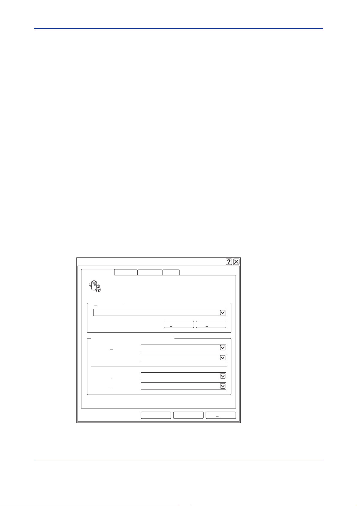
4.4.4 Communication setting (HAR T communication)
This subsection describes the procedures to change the communication related setting of
FieldMate. Please try these procedures after you start FieldMate and if you e xperience that
communication is not correctly established. Please ref er to 4.6.2.
(1) Communication port setting on FieldMate
1. Clic k the [Tool] --> [HART Modem Configuration..] at FieldMate window .
2. Select com port number .
3. Clic k the [OK] b utton.
F0433E.EPS
Figure 4.12 HART Modem configuration
All Rights Reserved Copyright © 2006, Yokogawa Electric Corporation IM 01C25R51-01E
Page 36

<Toc> <Ind> <4. Preparation>
Select COM port number.
F0434E.EPS
Figure 4.13 COM port
Please refer to FieldMate User's manual for details .
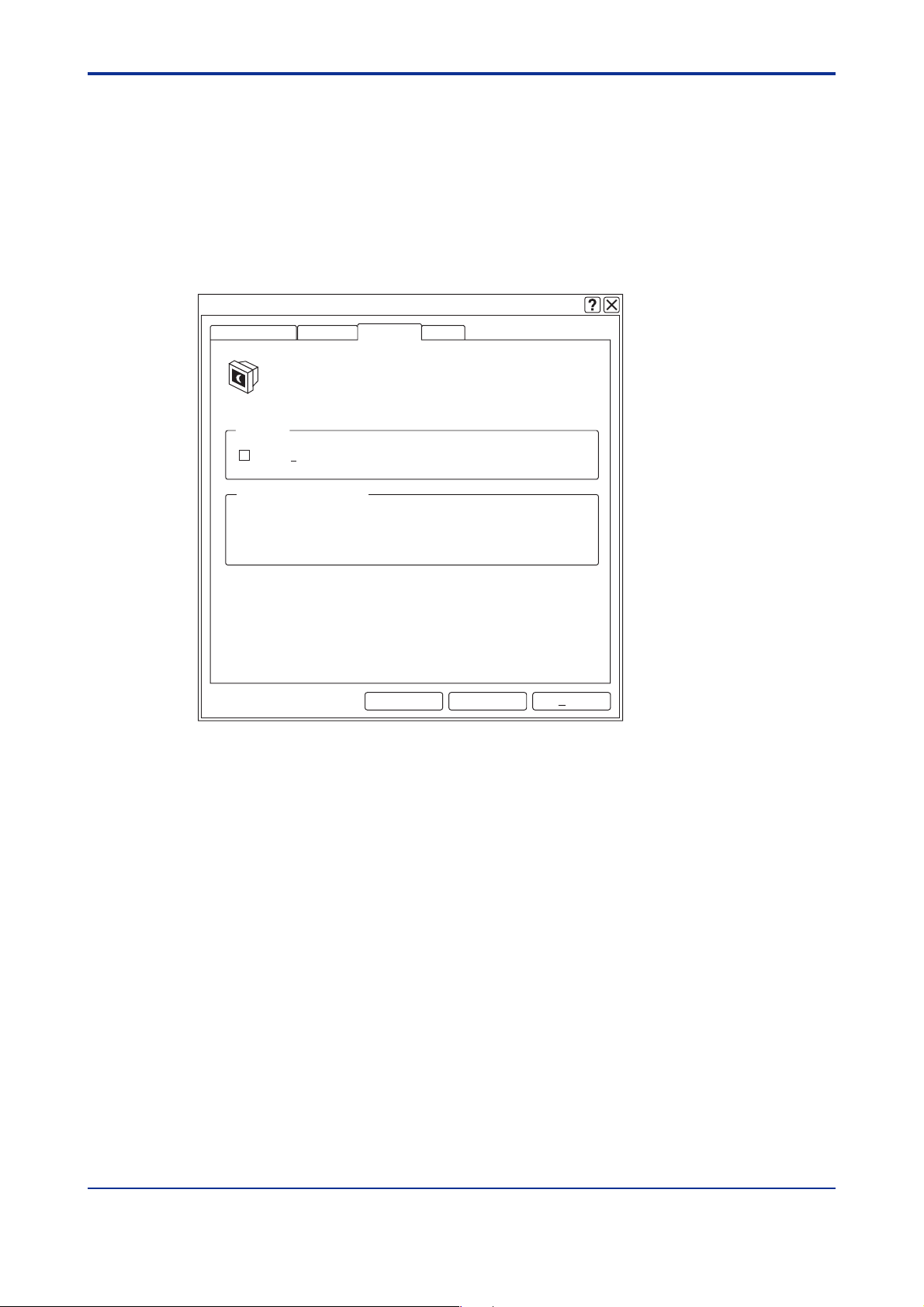
(2) Communication address setting on FieldMate
In FieldMate, the default setting of maximum scan v alue of communication address is “0”.
If the transmitter’s address is other than “0”, FieldMate cannot distinguish the tr ansmitter .
Therefore, the setting should be changed to the correct v alue.
1. Clic k the [Tool] --> [HART Modem Configuration..] at FieldMate window .
2. Select address number.
4-13
3. Clic k the [OK] b utton.
Maximum value of communication
Addressfor scaning
F0435E.EPS
Figure 4.14 Address Setting
Please refer to FieldMate for detail.
4.5 Initial Setting (FF Communication)
4.5.1 EJX910A
Address and Tags (PD Tag and VFD Tag) must be set in the EJX910A.
IMPORTANT
FSA120 does not support address setting. Use general purpose Fieldbus setting tool for
setting an address and tags. After using gener al purpose Fieldbus setting tool, e xit from
the program before starting EJX910 FF DTM. Please also refer to 4.7.1 FF comm unication
(Node Address).
4.5.2 Install NI-FBUS Card
Install the NI-FBUS card on PC.
All Rights Reserved Copyright © 2006, Yokogawa Electric Corporation IM 01C25R51-01E
Page 37

<T oc> <Ind> <4. Preparation>
4.5.3 NI-FBUS Setting (Interface Configuration Utility)
Please define the NI-FBUS setting as follows .
IMPORTANT
Activate the program as an Administrator or user with an Administr ative authority.
(1) Activate the program
On PC, click the f ollo wing order and activate the prog ram
Click [Start] --> [All Programs] --> [National Instrument] --> [NI-FBUS] --> [Interface
Configuration Utility]
4-14
Figure 4.15a Starting NI-FBUS Utility
(2) Select the port
On the screen shown up , select “Port0" and press “Edit”.
Figure 4.15b NI-FBUS Interface Config Screen
F0418E.EPS
F0419E.EPS
All Rights Reserved Copyright © 2006, Yokogawa Electric Corporation IM 01C25R51-01E
Page 38

<Toc> <Ind> <4. Preparation>
(3) Setting(if Link Master Device e xits in the segment)
After that, on the screen shown up, select the items indicated as belo w .
F0420E.EPS
Figure 4.15c NI-FBUS H1 Port Properties (1)
Device Address: Select [Visitor]
4-15
Device Type : Select [Basic Device]
Usage : Select [NI-FBUS]
CAUTION
Do not set the NI-FBUS card to Link Master Device in the Fieldbus segment where other
host may exist.
Setting may cause disturbance of control.
(4) Setting (if no Link Master Device exists in the segment)
After that, on the screen shown up, select the items indicated as belo w .
F0421E.EPS
Figure 4.15d NI-FBUS H1 Port Properties (2)
All Rights Reserved Copyright © 2006, Yokogawa Electric Corporation IM 01C25R51-01E
Page 39

<T oc> <Ind> <4. Preparation>
Device Address: Select [Visitor]
Device Type : Select [Link Master De vice]
Usage : Select [NI-FBUS]
4.5.4 Start NI-FBUS Communications Manager
Please Start the NI-FBUS Communications Manager as follows.
Click [Start] --> [All Programs] --> [National Instrument] --> [NI-FBUS] -->
[NI-FBUS Communications Manager].
F0422E.EPS
Figure 4.15e Starting NI-FBUS
IMPORTANT
4-16
When running the program, log-in the Windows as an Administr ator or an user with an
administrative authority.
4.5.5 Connect the EJX910A to the power supply
Please refer to User’ s manual IM 01C25 R03-01E “EJX910A Fieldbus Comm unication.”
4.5.6 Connect the NI-FBUS card to the EJX910A
CAUTION
FSA120 is the software tool which is purposed for the setup and maintenance. Do not try
connecting it to the EJX910A which is under actual operation in the process. Bef ore connecting NI-FBUS card to the segment, make sure that the process which is controlled by
the segment is off-lined.
All Rights Reserved Copyright © 2006, Yokogawa Electric Corporation IM 01C25R51-01E
Page 40

<Toc> <Ind> <4. Preparation>
NI-FBUS Card
4-17
Terminator
FF Device
+
-
Across the FF device.
*
Figure 4.16 Connection example for FF
*
Terminator
Loop Power
Supply
+
-
F0423E.EPS
4.6 Start FDT frame application
This section describes the operation of DTM with using FieldMate.
For the detailed operation of FieldMate , refer to User's man ual of FieldMate.
IMPORTANT
When running the program, log-in the Windows as an Administr ator or an user with an
administrative authority.
4.6.1 Update DTM Browser
After new DTM is installed, click “DTM Bro wser”, so as to confirm that the designated DTM
is correctly installed.
Click [Start] --> [All Programs] --> [Y OK OGA W A FieldMate] --> [Tool] --> [DTM browser]
All Rights Reserved Copyright © 2006, Yokogawa Electric Corporation IM 01C25R51-01E
Page 41

<T oc> <Ind> <4. Preparation>
4.6.2 Start FieldMate
Starting FieldMate by following operation.
(1) Click [Start] --> [All Programs] --> [Y OKOGAWA FieldMate] --> [FieldMate]
4-18
Figure 4.17a Start FieldMate
F0424E.EPS
(2) Default Scan Segment is to select the communication protocol of the segment to be
scanned on startup. Select [HAR T] or [FF-H1] and clic k [OK].
Figure 4.17b Select HART/FF
F0425E.EPS
All Rights Reserved Copyright © 2006, Yokogawa Electric Corporation IM 01C25R51-01E
Page 42

<Toc> <Ind> <4. Preparation>
(3) FieldMate Segment Vie wer window.
Open Segment View er on FieldMate.
A device icon appears on the window if it is successful to connect to FieldMate. If not, “No
device found” message is sho wn on the window .
If a connected device icon does not appear , check that initial setting f or comm unication is
correctly done. Ref er to section 4.4 for HAR T and 4.5 f or FF.
4-19
Figure 4.17c Segment Vie wer
F0426E.EPS
NOTE
How to confirm EJX910DTM version number.
Click [Action]--> [Select DTM] to select the target de vice.
Confirm version number .
F0428-02E.EPS
Figure 4. 17d Confirm Version of EJX910DTM
All Rights Reserved Copyright © 2006, Yokogawa Electric Corporation IM 01C25R51-01E
Page 43

<T oc> <Ind> <4. Preparation>
F0428-03E.EPS
Figure 4. 17e Version Number of EJX910 DTM
4.6.3 Start EJX910 DTM
(1) Start DTM Works
Select the icon of the target device for configur ation in the window.
Click the [Action] --> [Assign DTM]
4-20
Figure 4.18 Start DTM Works
All Rights Reserved Copyright © 2006, Yokogawa Electric Corporation IM 01C25R51-01E
F0427E.EPS
Page 44

<Toc> <Ind> <4. Preparation>
(2) Online Parameter windo w appears.
It may takes about one minute to open Online P arameter windo w .
F0428E.EPS
Figure 4. 19 Online P arameter Window
4-21
4.6.4 Save DTM Infomation
If “Sav e to file” is perf ormed, a device parameter snapshot is sav ed to an e xternal file-.dfs
file, which includes the following parameters .
• User Flow parameters
• Transmitter Flow parameters
• Transmitter General parameters
For a file f ormat of .dfs, refer to “File F ormat” of section 7.
This command is enabled while communication with a device is disconnected.
1. Clic k the [Device] --> [Disconnect] at DTM Works window.
2. Clic k the [File] --> [Sav e to file] at DTM W orks window .
3. Clic k the [OK] b utton.
Figure 4.20 Confirmation Message in Saving .dfs file
F0429E.EPS
4. Sav e .dfs file in the computer .
All Rights Reserved Copyright © 2006, Yokogawa Electric Corporation IM 01C25R51-01E
Page 45

<T oc> <Ind> <4. Preparation>
NOTE
• .dfs file is not compatible among diff erent communication.
• .dfs file is not compatible among diff erent fr ame applications.
4.6.5 Exit FieldMate and DTM Works
DTM W orks and FieldMate are ended by closing each window.
1. Clic k the [File] --> [Exit] at DTM W orks window .
2. Clic k the [File] --> [Exit] at FieldMate window.
4.7 EJXMVT ool Activ ation
4.7.1 How to Activate
Start EJX910DTM. (see 4.6.3)
4-22
> Start DTM Works.
> Select [Device] --> [Additional Functions] --> [Flow Configuration Wizard]
• The f ollowing screen appears only when this prog ram is run for the first time .
Figure 4.21 EJXMVTool Activ ation Screen
Enter the EJXMVTool license number, and Click [Check and Sav e].
F0430E.EPS
NOTE
You must enter whole license number includeing ‘-’ .
All Rights Reserved Copyright © 2006, Yokogawa Electric Corporation IM 01C25R51-01E
Page 46

<Toc> <Ind> <4. Preparation>
4-23
Figure 4.22 Software License Form
F0431E.EPS
Once the license number is confirmed, Flow Configuration Wizard screen belo w appears.
F0432E.EPS
Figure 4.23 T op Menu Screen of Flow Configuration Wizard
All Rights Reserved Copyright © 2006, Yokogawa Electric Corporation IM 01C25R51-01E
Page 47

Blank Page
Page 48

<Toc> <Ind> <5. Operation Specification for EJX910A Configuration>
5. Operational Flow
Following is an e xample of configuration procedures using A uto Compensation Mode .
(A) New Configur ation (e xample f or using FieldMate project file)
(B) Configure with e xisting Configuration File (dfs file)
(C) Configure with existing Configuration File (example for using XMV file)
(D) Configure with existing Configuration File (import:XMV file, PRM file,export:dfs file)
(A) New Configur ation (Example of using Auto Compensation Mode)
5-1
Upload
parameters
1
from the
device
Perform
2
Flow
Configuration
Download
parameters
3
to the device
Confirm
flow
4
coefficient
Save
settings to
5
.dfs file
FieldMate
Menu
Assign DTM
DTM Works
Menu
Device
Device
Device
Device
Device
File
Sub MenuStep Sub Menu Procedure Description
Online Parameter
screen is opened
ParameterDevice
Upload from
1)
device
Additional
Functions
Download
to device
Additional
functions
Disconnect
Save to
file…
2)
Offline
Parameter
Flow
Configuration
Wizard
Obtain Flow
Coefficient
Initialize menu
Flow Configuration
Mode
Primary Element and
Pipe Setup
Fluid type Setup
Fluid Operating
Range Setup
Fluid Physical
Property Setup
Export -> XMV menu
Report
Apply
Open Offline Parameter
window.
Upload T ransmitter Flow
parameters and Transmitter
General parameters.
Edit T ransmitter General
parameters and Apply Offline
Database
Initialization(Needed only if
configuration has been done
before)
Edit User Flow parameters.
Select Auto Compensation
Mode
Export User Flow parameters
and Transmitter Flow parameters
Export the User flow parameters
in CSV file format.
Apply T ransmitter Flow
parameters to Offline Database
Download T ransmitter Flow
parameters and Transmitter
General parameters.
You can check th flow
coefficient. The v alue is sa v ed in
a log file: “Flo wCoeffLog”.
Goes offline
Save the XXXXXX.dfs
User Flow parameters,
Transmitter Flow parameters
and T ransmitter General
parameters.
T0501E.EPS
All Rights Reserved Copyright © 2006, Yokogawa Electric Corporation IM 01C25R51-01E
Page 49

<T oc> <Ind> <5. Operation Specification for EJX910A Configuration>
1)Before starting operation, execute ‘Upload from de vice’, so that the general par ameters
of the transmitter in the offline database are synchronized with the device . Upload data
from the transmitter does not include User Flow Par ameters.
*: User Flow P arameters consist of primary device information, fluid information and
operating condition.
2)Executing ‘Download to de vice’ will write both Transmitter Flow Parameters and Transmit-
ter General Parameters into the de vice. Before executing ‘Download to device’, e x ecute
‘Upload from device’, so as to make the general par ameters of the transmitter in the
offline database synchronized with the device.
Download data to the transmitter does not include User Flow P arameters.
(B) Configure with e xisting configuration file (dfs file)
5-2
Step
Open Offline
1
Parameter
window.
Open .dfs file
and download
2
parameters
to the device
Confirm
flow
3
coefficient
FieldMate
Menu
Assign DTM
DTM Works
Menu
File
Device
Device
Device
Sub Menu Sub Menu Procedure Description
Online Parameter
screen is opened
DisconnectDevice
ParameterDevice
Load from
file…
Download
to device
Additional
functions
Disconnect
Offline
Parameter
1)
Obtain Flow
Coefficient
Goes offline
Open Offline Parameter
window.
Load the XXXXXX.dfs
User Flow parameters,
Transmitter Flow parameters
and T ransmitter General
parameters.
Edit T ransmitter General
parameters and Apply to
Offline Database
Goes onlineConnectDevice
Download T ransmitter Flow
parameters and Transmitter
General parameters.
You can check th flow coefficient.
The value is saved in a log file:
“FlowCoeffLog”.
Goes offline
T0502E.EPS
1)Before starting operation, execute ‘Upload from de vice’, so that the general par ameters
of the transmitter in the offline database are synchronized with the device. Upload data
from the transmitter does not include User Flow P arameters.
*: User Flow P arameters consist of primary device information, fluid inf ormation and
operating condition.
All Rights Reserved Copyright © 2006, Yokogawa Electric Corporation IM 01C25R51-01E
Page 50

<Toc> <Ind> <5. Operation Specification for EJX910A Configuration>
(C) Configure with existing Configuration File (XMV file)
5-3
Step
Upload
parameters
1
from the
device
Import Xmv
file and modify
2
flow
configuration
Download
3
parameters
Confirm
flow
4
coefficient
FieldMate
Menu
Assign DTM
DTM Works
Menu
Device
Device
Device
Device
Device
Sub Menu Sub Menu Procedure Description
Online Parameter
screen is opened
ParameterDevice
Upload from
1)
device
Additional
functions
Download
to device
Additional
functions
Disconnect
2)
Offline
Parameter
Flow
Configuration
Wizard
Obtain Flow
Coefficient
Import ->Import XMV
Flow Configuration
Mode
Primary Element and
Pipe setup
Fluid type setup
Fluid Operating
Range setup
Fluid Physical
property setup
Apply
Open Offline Parameter
window.
Upload T ransmitter Flow
parameters and Transmitter
General parameters.
Edit T ransmitter General
parameters and Apply to
Offline Database
Specify the target Flow Config
file “XXXXXX.xmv”
Import User Flow parameters,
Transmitter Flow parameters.
Confirm User Flow parameters.
Apply T ransmitter Flow
parameters to Offline Database
Download T ransmitter Flow
parameters and Transmitter
General parameters.
You can check th flow coefficient.
The value is saved in a log file:
“FlowCoeffLog”.
Goes offline
T0503E.EPS
1) Before starting operation, execute ‘Upload from device’, so that the gener al parameters
of the transmitter in the offline database are synchronized with the de vice.
Upload data from the transmitter does not include User Flow P arameters .*
*: User Flow Par ameters consist of primary device information, fluid information and
operating condition.
2) Executing ‘Download to de vice’ will write both Transmitter Flow P arameters and Transmit-
ter General Par ameters into the de vice. Bef ore e x ecuting ‘Download to device’, e xecute
‘Upload from device’, so as to make the general par ameters of the transmitter in the
offline database synchronized with the device.
Download data to transmitter does not include User Flow P ar ameters.
All Rights Reserved Copyright © 2006, Yokogawa Electric Corporation IM 01C25R51-01E
Page 51

<T oc> <Ind> <5. Operation Specification for EJX910A Configuration>
(D) Configure with existing Configuration File (import:XMV and PRM file,export:dfs file)
Applicable only f or FSA210 user .
5-4
Step
Upload
parameters
1
from the
device
Import existing
file and
cofirm/modify
2
flow
configuration
Download
3
parameters
Confirm
flow
4
coefficient
Save
parameters
5
to .dfs file
FieldMate
Menu
Assign DTM
DTM Works
Menu
Device
Device
Device
Device
Device
File
Sub Menu Sub Menu Procedure Description
Online Parameter is
open
ParameterDevice
Upload from
1)
device
Additional
functions
Download
to device
Additional
functions
Disconnect
Save to
file…
2)
Offline
Parameter
Flow
Configuration
Wizard
Obtain Flow
Coefficient
Import ->Import XMV
Import ->Import PRM
(HARTonly)
Flow Configuration
Mode
Primary Element and
Pipe setup
Fluid type setup
Fluid Operating
Range setup
Fluid Physical
property setup
Apply
Open Offline Parameter
window.
Upload T ransmitter Flow
parameters and Transmitter
General parameters.
Specify the target Flow Config
file “XXXXXX.xmv”
Import User Flow parameters,
Transmitter Flow parameters.
“XXXXXX.prm” to be edited.
HART Transmitter General
parameters.(FSA210 user only)
Confirm User Flow parameters.
Apply T ransmitter Flow
parameters to Offline Database
Download T ransmitter Flow
parameters and Transmitter
General parameters.
If required, you can check th flow
coefficient. The value is saved in
a log file: “Flo wCoeffLog”.
Goes offline
Save the XXXXXX.dfs
User Flow parameters,
Transmitter Flow parameters
and T ransmitter General
parameters.
T0504E.EPS
1)Before starting operation, execute ‘Upload from de vice’, so that the general par ameters
of the transmitter in the offline database are synchronized with the device .
Upload data from the transmitter does not include User Flow Par ameters.*
*: User Flow P arameters consist of primary device information, fluid inf ormation and
operating condition.
2)Executing ‘Download to de vice’ will write both Transmitter Flow P arameters and Transmit-
ter General Parameters into the de vice. Before executing ‘Download to device’, execute
‘Upload from device’, so as to make the gener al parameters of the transmitter in the
offline database synchronized with the device.
Download data to transmitter does not include User Flow P arameters.
All Rights Reserved Copyright © 2006, Yokogawa Electric Corporation IM 01C25R51-01E
Page 52

<Toc> <Ind> <6. Displa y Specification >
6. Display Specification
Following sho ws a main items in the menu, e xcluding the items specific to FieldMate.
NOTE
Displayed items ma y slightly diff er according to communication protocol.
(1) Menu and Function (Example of HART)
Connect
Disconnect
Upload from device
Download to device
Parameter
Device
(EJX
Additional
910)
functions
Delete device
Print
Properties
Menu Submenu Functions
Load from a
transmitter.
Store to a transmitter.
Offline Parameter
Online Parameter
Calculate flow
configuration data of a
transmitter.
Initialization (Needed
only if configuration
has been done before)
Flow configuration file
management
Flow configuration
report file
EJXMVTool
Instruction Manual
Version information
Obtain Flow coefficient
from T ransmitter
EJXMVTool
Instruction Manual
Version information
Flow
Configuration
Wizard
Obtain Flow
Coefficient
Initialize
Import
Export
Report
Help
Help
Initialize
Import XMV
Import PRM
Export XMV
Report
EJXMVTool
Help
EJXMVTool
About
EJXMVTool
Help
EJXMVTool
About
Transmitter
Management
Refer to
section 6.1
Refer to
section 6.1
6-1
Reference
Flow
Parameter
Refer to
sections 6.3
and 6.4
Refer to
section 6.2
Refer to
section 6.5
T0601E.EPS
All Rights Reserved Copyright © 2006, Yokogawa Electric Corporation IM 01C25R51-01E
Page 53

<T oc> <Ind> <6. Display Specification >
Download
to Device *
Upload from
De
v
ic
e *
Import/Export
Import/Export
(2) DTM W orks Menu Structure (Example of HART)
Initialize
Import XMV
Import PRM
(HART only)
Connect
Disconnect
-----Parameter
Additional functions
-----Show and Compare parameters...
-----Upload from device
Download to device
-----Print
-----Property
Figure 6.1 Menu structure
Export XMV
Online Parameter
Offline Parameter
Diag/Service
Observer
Flow Configuration Wizard
Obtain Flow Coefficient
-----About
-----Refresh online Data
Online Parameter
Offline Parameter
Diag/Service
Observe
Report
EJXMVTool Help
EJXMVTool About
F0601E.EPS
F0601E.EPS
6-2
(3) Data Flow Diagram
Compatible between different frame applications
Compatible between HART and FFDTMs
Xmv file
User Flow
Parameters
initialize
Import/Export
Import/Export
Flow Configuration
User Flow
Parameters
(note2)
* : Online function (executed while connected)
(note1) EJXMVTool calculates Transmitter Flow Parameters
based on the User Flow Parameters. A transmitter
does not hold User Flow Parameters.
(note2) User Flow Parameters consist of primary element
information, fluid information, and operating condition.
(note3) Generated by FSA210.
Can be imported to HART DTM.
Transmitter Flow
Parameters
Wizard
Flow
Configuration
Sensor Input
(DP,SP,ET)
Obtain Flow
Coefficient Module
Simulation Mode
(
Simulated Sensor Input
(DP,SP,ET)
t
t
Transmitter
Parameters
Sensor
Impor
Impor
t
t
/Expor
/Expor
Flow
User Flow
Download
Download
to Device *
to Device *
(note1)
Parameters
Report File (CSV)
s
C
*
Parameters(csv)
up
User Flow
e as
av
/S
Open
Offline Database
Transmitter Flow Parameters
Transmitter General
Parameters
ice *
ice *
v
v
De
De
Upload from
Upload from
Transmitter (EJX910A)
Transmitter Flow
Parameters
Transmitter General
Parameters
Open/Save a
t
por
x
E
Apply
FCW start
INPUT
)
OF
Online Parameterization *
Online
Parameterization
Transmitter
General Parameters
Figure 6.2 Data flow diagram
Not compatible between different frame applications
Not compatible between HART and FF DTMs
dfs file
Transmitter
General
Parameters
Save t
Load
from /
o
Offline
Transmitter
General Parameters
Obtain Flow
Coefficient Module
Process Value
(DP,SP,ET)
Flow Coefficient
(Flow, Density, Viscosity, Gas
Expansion Factor, Discharge
Coefficient, Reynolds No.)
S
tart Up
Enter
OFC
OFC
*
Transmitter
Flow
Parameters
Parameterization
*
PRM file
HART
Transmitter
General
Parameters
Import
F0602E.EPS
(note3)
All Rights Reserved Copyright © 2006, Yokogawa Electric Corporation IM 01C25R51-01E
Page 54

<Toc> <Ind> <6. Displa y Specification >
6.1 T ransmitter Management
Transmitter management is a function of EJX910 DTM.
Please refer to EJX910DTM HELP for detail.
Please also refer to FieldMate User’ s Manual f or operation.
6-3
Device Help
(HART/FF)
Figure 6.3 DTM HELP
Click here to refer EJX910
?
DTM HELP for detail (FF)
6.1.1 Connect / Disconnect
F0603E.EPS
Click here to refer
?
EJX910DTM HELP for
detail. (HART)
(1) How to Connect
Click the [Device] --> [Connect]
Figure 6.4a How to Connect
F0604aE.EPS
All Rights Reserved Copyright © 2006, Yokogawa Electric Corporation IM 01C25R51-01E
Page 55

<T oc> <Ind> <6. Display Specification >
IMPORTANT
In case of FF DTM, PD Tag and address are not shown on the online parameter screen.
Use Segment Vie wer to confirm the PD Tag and address of the device.
NOTE
‘Connect’ men u is active only while the tr ansmitter is disconnected.
(2) How to Disconnect
Click the [De vice] --> [Disconnect]
6-4
F0604E.EPS
Figure 6.4b How to Disconnect
NOTE
‘Disconnect’ men u is active only while the tr ansmitter is connected.
All Rights Reserved Copyright © 2006, Yokogawa Electric Corporation IM 01C25R51-01E
Page 56

<Toc> <Ind> <6. Displa y Specification >
6.1.2 Parameter
Online Parameter :
The parameters of the device can be edited directly in online status.
Offline Parameter :
The parameters of the device can be edited and stored in offline database.
Parameters saved in offline database can be downloaded to the device b y using “Do wnload
to Device” function. Parameters in the device can be uploaded to the offline database by
using “Upload from Device” function. Uploaded parameters can be edited in the offline
parameter window .
(1) Online Parameter
Click the [Device] --> [P ar ameter] --> [Online P arameter]
6-5
F0605E.EPS
Figure 6.5 Online Parameter
NOTE
‘Connect’ menu is activ e only while the transmitter is disconnected.
All Rights Reserved Copyright © 2006, Yokogawa Electric Corporation IM 01C25R51-01E
Page 57

<T oc> <Ind> <6. Display Specification >
(2) Offline Parameter
Click the [De vice] --> [P arameter] --> [Offline P arameter]
F0606E.EPS
Figure 6.6a Go to Offline Parameter
6-6
F0606-02E.EPS
Figure 6.6b Offline Parameter
All Rights Reserved Copyright © 2006, Yokogawa Electric Corporation IM 01C25R51-01E
Page 58

<Toc> <Ind> <6. Displa y Specification >
6.1.3 Upload from Device / Do wnload to Device
(1) How to load from a device
• HART DTM / FF DTM
1. Clic k the [De vice] --> [P arameter] --> [Offline P arameter]
2. Clic k the [De vice] --> [Upload from Device]
Uploading icon on the tool bar can also be used to ex ecute upload.
6-7
F0607E.EPS
Figure 6.7 Upload from Device
Offline Parameters (Transmitter Flow Parameters/Transmitter General P arameters) are
uploaded from the transmitter to offline database. The y can be edited using offline parameter window.
If an error occurs, an error message dialog will be display ed.
IMPORTANT
Before starting operation, execute ‘Upload from Device’, so that the general parameters of
the transmitter in the offline database is synchronized with the device .
NOTE
‘Upload from Device’ menu is active only while the transmitter is connected and Offline
Parameter window is open.
All Rights Reserved Copyright © 2006, Yokogawa Electric Corporation IM 01C25R51-01E
Page 59

<T oc> <Ind> <6. Display Specification >
(2) How to download to a de vice
• HART DTM
1. Clic k the [De vice] --> [P ar ameter] --> [Offline Par ameter]
2. Clic k the [De vice] --> [Download to De vice]
• FF DTM
1. Clic k the [De vice] --> [P ar ameter] --> [Offline Par ameter]
2. Chec k the chec kbo x of the function bloc ks downloading to a de vice.
6-8
F0608aE.EPS
Figure 6.8a Checkbox of Bloc ks to Download
IMPORTANT
• It is recommended to select all blocks.
• FTB block must be checked to do wnload T r ansmitter Flow parameters set b y Flo w
Configuration Wizard
3. Click the [Device] --> [Download to Device]
All Rights Reserved Copyright © 2006, Yokogawa Electric Corporation IM 01C25R51-01E
Page 60

<Toc> <Ind> <6. Displa y Specification >
Do wnloading icon on the tool bar can also be used to e xecute download.
F0608bE.EPS
Figure 6.8b Download to Device
6-9
NOTE
‘Download to Device’ men u is activ e only when the transmitter is connected and Offline
Parameter window is open.
All Rights Reserved Copyright © 2006, Yokogawa Electric Corporation IM 01C25R51-01E
Page 61

<T oc> <Ind> <6. Display Specification >
6.1.4 Print
Parameters can be printed out by using print function.
Click the [De vice] --> “Print”.
Select “Online P arameter”, “Offline P arameter”, “Diag/ Service”,.“Observe”,
6-10
Figure 6.9 Print
6.1.5 Properties
The EJX910 DTM version number is shown when this menu is clic k ed.
Click the [Device] --> “Property”.
F0609E.EPS
EJX910 DTM version number
F0610E.EPS
Figure 6.10 Property
All Rights Reserved Copyright © 2006, Yokogawa Electric Corporation IM 01C25R51-01E
Page 62

<Toc> <Ind> <6. Displa y Specification >
6.1.6 Additional functions
(1) Diag/Service (for HART)
Diagnostics related parameters are shown.
Click the [Device] --> [Additional Functions] --> [Diag/Service]
6-11
Figure 6.11a Diag/Service
(2) Observe (for HART)
Process variables related parameters are shown.
Click the [Device] --> [Additional Functions] --> [Observe]
F0611E.EPS
F0612E.EPS
Figure 6.11b Observe
All Rights Reserved Copyright © 2006, Yokogawa Electric Corporation IM 01C25R51-01E
Page 63

<T oc> <Ind> <6. Display Specification >
6.2 Flow P arameters Management
Flow Par ameters Management consists of Flow Configuration Wizard and Obtain Flo w
Coefficient. This manual describes about the file management in the Flow Configuration
Wizard in the sections 6.3 and 6.4, and Obtain Flow Coefficient in the section 6.5.
Flow Par ameters Management can be done from the Flow Configuration Wizard by the
following procedures
Click the [Device] --> [Additional Functions] --> [Flo w Configuration Wizard]
6-12
Figure 6.12 Top Menu Screen of Flow Configuration Wizar d
WARNING
The use of inappropriate materials can result in the leakage of corrosive process fluids and
cause injury to personnel and/or damage to plant facilities. Chec k wetted parts materials
and transmitter fill fluid for compatibility with the intended process fluid.
6.2.1 Initialize
Initialize flow configuration parameters .
NOTE
Initialize can be used only in the Flow Configuration Mode screen.
F0613E.EPS
All Rights Reserved Copyright © 2006, Yokogawa Electric Corporation IM 01C25R51-01E
Page 64

<Toc> <Ind> <6. Displa y Specification >
F0614E.EPS
Figure 6.13a Initializing
6-13
Figure 6.13b Initializing Message
6.2.2 Import
(1) Import Flow Configuration .XMV file.
NOTE
Refer to ‘7. File Format’ for inf ormation of file f ormat of Flow Configuration .XMV file.
Import can be used in the Flow Configuration Mode screen.
NOTE
The XMV file made on the FSA210 is compatible with FSA120.
F0614-02E.EPS
User Flow parameters and Transmitter Flow parameters can be imported.
All Rights Reserved Copyright © 2006, Yokogawa Electric Corporation IM 01C25R51-01E
Page 65

<T oc> <Ind> <6. Display Specification >
F0615-01E.EPS
Figure 6.14a Importing a File
NOTE
6-14
Flow Configuration Wizard R1.02.01 or later does not allow setting the gauge pressure to
the Reference pressure. If importing .XMV file in which the Reference pressure is configured as the gauge pressure using R1.02.00 or earlier, the f ollowing message is displa y ed.
Figure 6.14b Information Message for Reference Pressure
Reenter the absolute pressure equivalent to the display ed gauge pressure f or the Ref erence Condition in Fluid Operating Range Setup screen.
6.2.3 Export
User Flow parameters and Transmitter Flow parameters can be exported.
NOTE
F0615-02E.EPS
Refer to ‘7.1 Configur ation file’ f or inf ormation of file format of Flow Configuration .XMV file.
Export can be used only in the Flow Configuration Mode screen.
NOTE
The XMV file made on the FSA210 is compatible with FSA120.
All Rights Reserved Copyright © 2006, Yokogawa Electric Corporation IM 01C25R51-01E
Page 66

<Toc> <Ind> <6. Displa y Specification >
F0616E.EPS
Figure 6.15 Exporting a File
6.2.4 Report
6-15
Export user flow parameters in CSV File format.
NOTE
Report can be used only in the Apply Flow Configuration screen.
F0617E.EPS
Figre 6.16 Report
NOTE
User name on the report may be shown as “unknown” on those frame application which
does not support user authorization function.
All Rights Reserved Copyright © 2006, Yokogawa Electric Corporation IM 01C25R51-01E
Page 67

<T oc> <Ind> <6. Display Specification >
6.2.5 Help
(1) EJXMVTool Help
The EJXMVTool manual map opens when this menu is clicked.
6-16
F0618E.EPS
Figure 6.17 Help
NOTE
EJXMVTool Online Help uses Adobe Reader. Install Adobe Reader to vie w Online Help .
All Rights Reserved Copyright © 2006, Yokogawa Electric Corporation IM 01C25R51-01E
Page 68

<Toc> <Ind> <6. Displa y Specification >
(2) EJXMVTool About
The EJXMVTool DTM (Flow Configuration Wizard and Obtain Flow Cefficient) version
number is shown when this menu is click ed.
F0619E.EPS
Figure 6.18 About
6-17
The EJXMVTool DTM version number is also shown b y “Add or Remov e Program” of
Windows’ Control P anel.
Refer to “4.2.6 Ho w to confirm Version No. of EJXMVTool DTM.”
6.3 Flow Configuration Wizar d (Auto Compensation Mode)
6.3.1 Flow Configuration Mode
F0620E.EPS
Figure 6.19 Flow Configuration Mode screen
All Rights Reserved Copyright © 2006, Yokogawa Electric Corporation IM 01C25R51-01E
Page 69

<T oc> <Ind> <6. Display Specification >
Select desired flow configuration mode and click [Ne xt].
Flow Configuration Mode
•Auto Compensation Mode( Default)
Configuration of the fluid ph ysical properties and primary element for the EJX910 can
be performed using a dialog window .
• Basic Mode
Flow operation and density compensation are perf ormed conv entionally, with the flow
factors being input manually.
6.3.2 Primary Device and Pipe Setup
6-18
(1)
(3)
(4)
(6)
(8)
Figure 6.20 Primary Device and Pipe Setup Screen
(1) Primary Device Type
The device types are Selectab le from the follo wings:
Type
Orifice
Nozzle
Venturi
Fix
T0602E.EPS
(2)
(5)
(7)
F0621E.EPS
All Rights Reserved Copyright © 2006, Yokogawa Electric Corporation IM 01C25R51-01E
Page 70

<Toc> <Ind> <6. Displa y Specification >
(2) Primary Device Description
The primary device selectable from followings .
Table 6.1 Primary Device
Type
Orifice
Nozzle
Venturi
FIX
Orifice Corner Taps [ISO5167-1 1991]
Orifice Corner Taps [ISO5167-2 2003]
Orifice Corner Taps [ASME MFC-3M 1989]
Orifice Flange Taps [ISO5167-1 1991]
Orifice Flange Taps [ISO5167-2 2003]
Orifice Flange Taps [ASME MFC-3M 1989]
Orifice Flange Taps [AGA No.3 1992]
Orifice D and D/2 Taps [ISO5167-1 1991]
Orifice D and D/2 Taps [ISO5167-2 2003]
Orifice D and D/2 Taps [ASME MFC-3M 1989]
ISA1932 nozzle [ISO5167-1 1991/ ISO5167-3 2003]
Long radius nozzle [ISO5167-1 1991/ ISO5167-3 2003]
ASME FLOW NOZZLES [ASME MFC-3M 1989]
Venturi nozzle [ISO5167-1 1991/ ISO5167-3 2003]
Classical Venturi tube “as cast” convergent section [ISO5167-1 1991/ ISO5167-4 2003]
ASME Venturi Tubes With a rough Cast or Fabricated Convergent [ASME MFC-3M 1989]
Classical Venturi tube with a machined convergent section [ISO5167-1 1991/ ISO5167-4 2003]
ASME Venturi Tubes With a machined convergent section [ASME MFC-3M 1989]
Classical Venturi tube with a rough-welded sheet-iron convergent section
[ISO5167-1 1991/ ISO5167-4 2003]
Fixed Mode *
1
Primary Device
6-19
T0603E.EPS
*1 Sets the discharge coefficient and gas expansion factor to a fixed v alue
(3) Discharge Coefficient of the Primary Device
This parameter is active only when ‘Fix’ selected for [T ype].
Input the Discharge Coefficient manually when ‘Fix’ is selected.
(4) Primary Device Gas Expansion Factor
This parameter is active only when ‘Fix’ selected for [Type].
Input the Gas Expansion Factory manually when ‘Fix’ is selected.
(5) Primary Device Sizing
Set the following v alues and select a unit.
Diameter of Differential Producer
unit: mm (def ault)/in
measuring temperature: 20 (def ault)
unit: degC (def ault), degF, K elvin
(6) Primary Device Material
The primary device material selectable from followings.
Thermal expansion of the primary device is automatically calculated according to the
material.
All Rights Reserved Copyright © 2006, Yokogawa Electric Corporation IM 01C25R51-01E
Page 71

<T oc> <Ind> <6. Display Specification >
Table 6.2 Primary device material
Material Remarks
304 Stainless Steel
316 Stainless Steel
Carbon Steel
Hastelloy C
Monel
Default
T0604E.EPS
(7) Pipe Sizing
Set the following v alues and select a unit.
Pipe inside Diameter
unit: mm (def ault) / in
Measuring temperature: 20 (def ault)
unit: degC (def ault), degF, K elvin
(8) Pipe material
The pipe material selected from followings.
6-20
Thermal expansion of pipe is automatically calculated according to the material.
Table 6.3 Pipe material
Pipe Material Remarks
304 Stainless Steel
316 Stainless Steel
Carbon Steel
Hastelloy C
Monel
6.3.3 Fluid Setup
Auto compensation mode supported physical property database of fluid
Table 6.4 Fluid setup
Type Category
Gas or Steam
Liquid
Default
T0605E.EPS
Gas (DIPPR) DIPPR data base
AGA8 Detail Characterization Method
AGA8 Gross Characterization Method 1
Natural gas
Gas (custom data table)
Steam
Liquid (DIPPR)
Liquid (custom data table)
AGA8 Gross Characterization Method 2
ISO12213 molar-composition analysis
ISO12213 physical properties
User's numerical input
IAPWS/IF97 Water and steam(1997)
DIPPR data base
User's numerical input
Name/Method
T0606E.EPS
All Rights Reserved Copyright © 2006, Yokogawa Electric Corporation IM 01C25R51-01E
Page 72

<Toc> <Ind> <6. Displa y Specification >
(1)
(2)
(3)
F0622E.EPS
Figure 6.21 Fluid Type Setup
(1) Select the type of fluid.
6-21
• Gas or Steam (Default) (Go to (2).)
• Liquid (Go to (3).)
(2) When “Gas or Steam” is selected f or [Type], select the Category from the following;
• Natural Gas (Default)
• Steam
• Gas (DIPPR)
• Gas (Custom Data Table)
When “Natural Gas (Def ault)” is selected f or [Category], select the Fluid name/
Method from the followings;
• AGA8 Detail Characterization Method (Def ault)
• AGA8 Gross Characterization Method 1
• AGA8 Gross Characterization Method 2
• ISO12213 molar-composition analysis
• ISO12213 physical properties
When “Steam” is selected for [Category], select the Fluid name/Method from the follo w-
ings;
• Superheated and Saturated steam
• Saturated steam
When “Gas (DIPPR)” is selected f or [Category], select the Fluid name/Method from
the followings;
All Rights Reserved Copyright © 2006, Yokogawa Electric Corporation IM 01C25R51-01E
Page 73

<T oc> <Ind> <6. Display Specification >
Table 6.5 Physical property database
Fluid name Fluid name Fluid name
Acetic Acid Hydrogen Chloride Phosphoric Acid
Acetone Hydrogen Cyanide Propadiene
Acetonitrile Hydrogen Peroxide Propane
Acetylene Hydrogen Sulfide Propylene
Acrylonitrile Isobutane Pyrene
Air Isobutene Styrene
Allyl Alcohol Isobutylbenzene Sulfur Dioxide
Ammonia Isopentane Toluene
Argon Isoprene Trichloroethylene
Benzaldehyde Isopropanol Trichlorofluoromethane
Benzene m-chloronitrobenzene Vinyl Acetate
Benzoic Acid m-dichlorobenzene Vinyl Chloride
Benz Alcohol Methane Vinyl Cyclohexene
Biphenyl Methanol Water
Bromine Methyl Acrylate 1-Butene
Carbon Dioxide Methyl Ethyl Ketone 1-Decene
Carbon Monoxide Methyl Vinyl ether 1-Decanal
Carbon Tetrachloride Monochlorobenzene 1-Decanol
Chlorine n-Butane 1-Dodecene
Chlorodifluoromethane n-Butanol 1-Dodecanol
Chloroprene n-Butyraldehyde 1-Heptanol
Chlorotrifluoroethylene n-Butyronitrile 1-Heptene
Citric Acid n-Decane 1-Hexene
Cycloheptane n-Dodecane 1-Hexadecanol
Cyclohexane n-Heptadecane 1-Octanol
Cyclopentane n-Heptane 1-Octene
Cyclopentene n-Hexane 1-Nonanal
Cyclopropane n-nonane 1-Nonanol
Dichlorodifluoromethane n-Octane 1-Pentadecanol
Divinyl Ether n-Pentane 1-Pentanol
Ethane Neon 1-Pentene
Ethanol Neopentane 1-Undecanol
Ethylamine Nitric Acid 1,1,2,2-Tetrafluoroethane
Ethylbenzene Nitric Oxide 1,1,2-Trichloroethane
Ethylene Nitrobenzene 1,2,4-Trichlorobenzene
Ethylene Glycol Nitroethane 1,2-Butadiene
Ethylene Oxide Nitrogen 1,3-Butadiene
Fluorene Nitromethane 1,3,5-Trichlorobenzene
Furan Nitrous Oxide 1,4-Dioxane
Helium-4 Oxygen 1,4-Hexadiene
Hydrazine Pentafluoroethane 2-Methyl-1-Pentene
Hydrogen Phenol
2,2-Dimethylbutane
6-22
T0607E.EPS
When “Gas (Custom Data Table)” is selected f or [Category], Set the custom Fluid name/
Method in the blank box.
All Rights Reserved Copyright © 2006, Yokogawa Electric Corporation IM 01C25R51-01E
Page 74

<Toc> <Ind> <6. Displa y Specification >
(3) When “Liquid” is select for [Type], select the Category from the followings;
• Liquid (DIPPR)
• Liquid (Custom)
When Liquid (DIPPR) is selected for [Category], select the Fluid name/Method.
From 126 materials as shown in Tab le 6.5.
• Category: Liquid (Custom), set the Fluid name/Method in the blank bo x.
6.3.4 Natural Gas Setup
(1) AGA8 Detail Characterization
6-23
F0623E.EPS
Figure 6.22 Natural Gas Setup Screen (1)
Input the value as mole percent for each component shown in Tab le 6.6.
The each value must be specified with in the range sho wn in Table 6.6.
Total mole percent must become 100%.
• Standardize: Standardize the mole component v alue.
Click [Standardize] b utton when total mol percent does not become 100%.
• Reset: Reset the mole component value
•Total mole: Total mole percent is displayed
All Rights Reserved Copyright © 2006, Yokogawa Electric Corporation IM 01C25R51-01E
Page 75

<T oc> <Ind> <6. Display Specification >
Table 6.6 A GA 8 Mole Valid Range
#
1
2
3
4
5
6
7
8
CH4 Methane mole percent
N2 Nitrogen mole percent
CO2 Carbon Dioxide mole percent
C2H6 Ethane mole percent
C3H8 Propane mole percent
H2O Water mole percent
H2S Hydrogen Sulfide mole percent
H2 Hydrogen mole percent
9 CO Carbon Monoxide mole percent 0–3.0 %
10 O2 Oxygen mole percent 0–21 %
11 C4H10 i-Butane mole percent 0–6 % *
12 C4H10 n-Butane mole percent 0–6 % *
13 C5H12 i-Pentane mole percent 0–4 % *
14 C5H12 n-Pentane mole percent 0–4 % *
15 C6H14 n-Hexane mole percent 0–Dew Point % *3
16 C7H16 n-Heptane mole percent 0–Dew Point % *
17 C8H18 n-Octane mole percent 0–Dew Point % *
18 C9H20 n-Nonane mole percent 0–Dew Point % *
19 C10H22 n-Decane mole percent 0–Dew Point % *
20 He Helium mole percent 0–3.0 %
21 Ar ARGON 1-1.0%
Component
Mole Valid Range (Expanded Range)
0–100 %
0–100 %
0–100 %
0–100 %
0–12 %
0–Dew Point % *
0–100 %
0–100 %
1
1
2
2
6-24
3
3
3
3
3
T0608E.EPS
*1 ISOBUT ANE (C4H10) and n-BUTANE (C4H10)’ s sum cannot exceed 6 %.
*2 ISOPENTANE (C5H12) and n-Pentane (C5H12)’s sum cannot exceed 4 %.
*3 Upper limit De w P oint is not check ed by the tool
(2) AGA8 Gross Characterization Method 1
F0624E.EPS
Figure 6.23 Natural Gas Setup Screen (2)
All Rights Reserved Copyright © 2006, Yokogawa Electric Corporation IM 01C25R51-01E
Page 76

<Toc> <Ind> <6. Displa y Specification >
Table 6.7 Input & Valid Range (Expanded Range)
Mandatory
Optional
Contents
Real Gas Relative Density
CARBON DIOXIDE (CO2) mole
Volumetric Gross Heating Value
HYDROGEN (H2) mole
CARBON MONOXIDE (CO) mole
Expanded Range Remarks
0.554–0.87
0–30%
17.76–42.87 MJ/m3
(477–1150 BTU/ft3)
0–10%
0–3%
at 14.73 psi abs 60 °F
(at 101.56 kPa abs and 15.56 °F)
at 14.73 psi abs 60 °F
(at 101.56 kPa abs and 15.56 °F)
(3) AGA8 Gross Characterization Method 2
6-25
T0609E.EPS
Figure 6.24 Natural Gas Setup Screen (3)
Table 6.8 Input & Valid Range (Expanded Range)
Contents
Mandatory
Optional
Relative Density
CARBON DIOXIDE (CO2) mole
NITROGEN (N2)
HYDROGEN (H2) mole
CARBON MONOXIDE (CO) mole
F0625E.EPS
Expanded Range Remarks
0.554–0.87
0–30%
0–50%
0–10%
0–3%
at 14.73 psi abs 60 °F
(at 101.56 kPa abs and 15.56 °F)
T0610E.EPS
All Rights Reserved Copyright © 2006, Yokogawa Electric Corporation IM 01C25R51-01E
Page 77

<T oc> <Ind> <6. Display Specification >
(4) ISO12213 molar-composition analysis
F0626E.EPS
Figure 6.25 Natural Gas Setup Screen (4)
Input the value as mole percent for each component sho wn in Table 6.9.
6-26
The each value must be specified within the range shown in Table 6.9.
Total mole percent must become 100%.
• Standardize: Standardiz e the mole component value.
Click [Standardize] button when total mol percent does not become 100%.
• Reset: Reset the mole component value
•Total mole: Total mole percent is displayed
All Rights Reserved Copyright © 2006, Yokogawa Electric Corporation IM 01C25R51-01E
Page 78

<Toc> <Ind> <6. Displa y Specification >
Table 6.9 ISO12213 Mole Valid Range
#
1
2
3
4
5
6
7
8
CH4 Methane mole percent
N2 Nitrogen mole percent
CO2 Carbon Dioxide mole percent
C2H6 Ethane mole percent
C3H8 Propane mole percent
H2O Water mole percent
H2S Hydrogen Sulfide mole percent
H2 Hydrogen mole percent
9 CO Carbon Monoxide mole percent 0–3 %
10 O2 Oxygen mole percent 0–0.02 %
11 C4H10 i-Butane mole percent 0–1.5 *
12 C4H10 n-Butane mole percent 0–1.5 *
13 C5H12 i-Pentane mole percent 0–0.5 % *
14 C5H12 n-Pentane mole percent 0–0.5 % *
15 C6H14 n-Hexane mole percent 0–0.1%
16 C7H16 n-Heptane mole percent 0–0.05%
17 C8H18 n-Octane mole percent 0–0.05%
18 C9H20 n-Nonane mole percent 0–0.05%
19 C10H22 n-Decane mole percent 0–0.05%
20 He Helium mole percent 0–0.5 %
21 Ar ARGON 0–0.02%
Component
Mole Valid Range (Expanded Range)
50–100 %
0–50 %
0–30 %
0–20 %
0–5 %
0–0.015
0–0.02 %
0–10%
1
1
2
2
6-27
T0611E.EPS
*1 ISOBUT ANE (C4H10) and n-BUTANE (C4H10) ‘s sum cannot e xceed 1.5 %.
*2 ISOPENT ANE (C5H12) and n-P entane (C5H12) ‘s sum cannot exceed 0.5 %.
(5) ISO12213 physical properties
F0627E.EPS
Figure 6.26 Natural Gas Setup Screen (5)
All Rights Reserved Copyright © 2006, Yokogawa Electric Corporation IM 01C25R51-01E
Page 79

<T oc> <Ind> <6. Display Specification >
Table 6.10 Input & Valid Range (Expanded Range)
Mandatory
Optional
Contents
Relative Density
CARBON DIOXIDE (CO2) mole
Volumetric Gross Heating Value
HYDROGEN (H2)
Expanded Range Remarks
0.55–0.9
0–30%
20–48 MJ/m3
0–10%
at 0°C, 1.01325 bar abs
at 25°C, 1.01325 bar abs
6.3.5 Fluid Operating Range Setup
(1) Gas or Steam(excluding Category :Saturated steam),
6-28
T0612E.EPS
F0628E.EPS
Figure 6.27 Fluid Operating Range Setup Screen (1)
Input operating ranges and select units
Pressure and Temperature units are selectable from f ollowing.
Pressure unit: kP a abs, bar abs , psi abs, kPa gauge, bar gauge, psi gauge
Atmospheric Pressure unit: psi abs, bar abs , kP a abs
Temperature unit: degC, degF, Kelvin
Input reference condition and select units
Pressure and Temperature units are selectable from f ollowing.
Pressure unit: kP a abs, bar abs , psi abs
Temperature unit: degC, degF, Kelvin
All Rights Reserved Copyright © 2006, Yokogawa Electric Corporation IM 01C25R51-01E
Page 80

<Toc> <Ind> <6. Displa y Specification >
NOTE
• After clicking the [Next] button, if a “The specified oper ating condition includes both gas
and liquid phases.” information message is displayed, the oper ating condition is near the
acceptable limits for liquid and gas .
F0629E.EPS
Figure 6.28 W arning message
• Please confirm the density value on the f ollowing page (fluid ph ysical property setup
page) and continue configuration.
• If the temperature and pressure range input on the Fluid Operating Range Setup is too
wide, there is a probability of the calculation error of density is big.
• These ranges are used only for the density and viscosity calculation.
• Ranges of Transmitter are not changed.
6-29
(2) Gas or Steam (Category :Saturated steam)
Figure 6.29 Fluid Operating Range Setup Screen (2)
Input operating range and select units
F0630E.EPS
Pressure unit is selectable from kPa abs , bar abs, psi abs, kP a gauge, bar gauge , psi gauge
Atmospheric Pressure unit is selectable from: psi abs , bar abs, kP a abs
Input reference condition and select units
Pressure unit is selectable from kPa abs , bar abs, psi abs
All Rights Reserved Copyright © 2006, Yokogawa Electric Corporation IM 01C25R51-01E
Page 81

<T oc> <Ind> <6. Display Specification >
NOTE
• After clicking the [Next] button, if a “The specified operating condition includes both gas
and liquid phases. ” information message is displayed, the operating condition is near the
acceptable limits for liquid and gas.
F0631E.EPS
Figure 6.30 W arning messa ge
• Please confirm the density value on the following page (fluid physical property setup
page) and continue configuration.
• If the pressure range input on the Fluid Operating Range Setup is too wide, there is a
probability of the calculation error of density is big.
• These ranges are used only for the density and viscosity calculation.
• Ranges of Transmitter are not changed.
6-30
(3) Liquid
Figure 6.31 Fluid Operating Range Setup Screen (3)
Input operating range and select units
F0632E.EPS
Temperature unit is selectable from degC, degF or K elvin.
Input reference condition and select units
Temperature unit is selectable from degC, degF or K elvin.
All Rights Reserved Copyright © 2006, Yokogawa Electric Corporation IM 01C25R51-01E
Page 82

<Toc> <Ind> <6. Displa y Specification >
NOTE
• Please confirm the density value on the f ollowing page (fluid ph ysical property setup
page) and continue configuration.
• If the temperature range input on the Fluid Operating Range Setup is too wide, there is a
probability of the calculation error of density is big.
• This range are used only for the density and viscosity calculation.
• Range of Transmitter are not changed.
6.3.6 Fluid Physical Pr operty Setup
(1) Gas or Steam
(Natural gas ISO physical properties setup)
6-31
F0633E.EPS
Figure 6.32 Fluid Physical Property Setup Screen(1)
Confirm the value of density , viscosity, molecular weight and isentropic.
Units can selectable from following.
Density: kg/m3 (Def ault), lb/ft3
Viscosity: P a Sec, lb/ft sec
NOTE
The density and viscocity value can be customized.
The Isentropic exponent value can be customized.
The molecular weight value can be customized.
The value is shown after entering return key.
All Rights Reserved Copyright © 2006, Yokogawa Electric Corporation IM 01C25R51-01E
Page 83

<T oc> <Ind> <6. Display Specification >
NOTE
If the “There is a calculation error with the given input of pressure and temper ature .Please
fill out another value” error message is displayed when the Next button is clic ked, the
temperature and pressure range input on the Fluid Operating Range Setup is narrow.
Please specify another value (wider range) and try again.
F0634E.EPS
Figure 6.33 Information message for setting range
(2) Liquid
6-32
F0635E.EPS
Figure 6.34 Fluid Physical Property Setup Screen(2)
Confirm the value of density, viscosity and molecular weight.
Units can selected from following.
Density: kg/m3 (Def ault), lb/ft3
Viscosity: P a Sec , lb/ft sec
NOTE
The density and viscocity value can be customized.
The viscosity value can be customized.
The molecular weight value can be customized.
The value is shown when entering return key.
All Rights Reserved Copyright © 2006, Yokogawa Electric Corporation IM 01C25R51-01E
Page 84

<Toc> <Ind> <6. Displa y Specification >
6.3.7 Apply Flow Configuration
F0636E.EPS
Figure 6.35 Apply Flow Configuration
6-33
In order to download the configuration to the transmitter please select “Apply”.
Then perform download / store to device from y our frame application.
Please refer to Chapter 5 and Figure 6.2.
6.4 Flow Configuration Wizar d (Basic Mode)
6.4.1 Flow Configuration Mode
F0637E.EPS
Figure 6.36 Flow Configuration Mode Screen (Basic mode)
All Rights Reserved Copyright © 2006, Yokogawa Electric Corporation IM 01C25R51-01E
Page 85

<T oc> <Ind> <6. Display Specification >
Flow Configuration Mode
•Auto Compensation Mode (Default)
Configuration of the fluid physical properties and primary element for the EJX910A can
be performed using a dialog window .
• Basic Mode
Flow operation and density compensation are performed conv entionally, with the flow
factors being input manually.
NOTE
1. The flow unit is not automatically converted in basic mode.
2. The flow range is set to LR V=0 and UR V=100 when the Flo w Configuration Mode is
changed to Basic Mode or Auto Compensation Mode.
6.4.2 Basic Mode Setup
Select a Fluid Type from “Gas” or “Liquid”.
6-34
(1) Gas (Default)
F0638E.EPS
Figure 6.37 Basic Mode Setup Screen
• Input Reference Temperature (Tb), Reference Static Pressure (SPb), and Kf actor .
NOTE
The static pressure value is according to the transmitter’ s abs and gauge selection (A/G
select). But same unit char acter is used f or both absolute and gauge.
All Rights Reserved Copyright © 2006, Yokogawa Electric Corporation IM 01C25R51-01E
Page 86

<Toc> <Ind> <6. Displa y Specification >
The procedure for setting the BASIC Mode is as follo ws. For details on how to calculate the
Kfactor, refer to the EJX910 Multivariable Transmitters User’s Man ual (IM 01C25R01-01E).
Table 6.11 Flow Operational Expression
Fluid
type
Liquid
Gas
Flow unit Category
Mass Flow
Normal·Standard
Volume Flow
Volume Flow
Mass Flow
Normal·Standard
Volume Flow
Volume Flow
*3
Kfactor = π/4NcC/ 1–β^4 ε d^2
Kfactor = π/4NcC/ 1–β^4 ε d^2
Kfactor = π/4NcC/ 1–β^4 ε d^2
Kfactor = π/4NcC/ 1–β^4 ε d^2
Kfactor = π/4NcC/ 1–β^4 ε d^2
Kfactor = π/4NcC/ 1–β^4 ε d^2
*1 mark indicate User Input
*2 Kfactor must be calculated according to the Flow unit category
*3 Reter to table 6.5, 6.6, 6.7
Table 6.12 Symbol
#
Symbol
Qm
1
Qv
2
Qv_norm
3
Nc
4
5
Kfactor
6
C
7
ε
8
9d
∆p
10
b
11
norm
12
Tb
13
T
14
SPb
15
SP
16
Mass Flow
Volume Flow
Normal·Standard Volume Flow
Unit convert factor
Basic flow Calculation factor
Discharge Coefficient
Expansion Factor
Diameter Ratio
Diameter of orifice
Differential Pressure
(Transmitter Setting unit)
Base Density on Tb, SPb Condition
Density on Normal, Standard condition
Reference temperature unit: K
Temperature unit: K
Reference static pressure unit: kPa abs
Static Pressure unit: kPa abs
The density rate of change per temperature
Temp K1
17
1degC of a density base value (value which
set 100% to 1)
For volume flow: set 0.
K Compressibility factor
18
Description
Kfactor *2 Flow Equation
2ρb
Qm or Qv or Qv_norm
= Kfactor
2ρb / ρ norm
P(1+Temp K1(T–Tb))
2 / ρb
2ρb1/K
Qm or Qv_norm
= Kfactor
PTb/TSP/SPb
2ρb1/K / ρ norm
Qv= Kfactor
2/(ρb1/K)
T0614E.EPS
PT/TbSPb/SP
6-35
*1
*1
*1
T0613E.EPS
All Rights Reserved Copyright © 2006, Yokogawa Electric Corporation IM 01C25R51-01E
Page 87

<T oc> <Ind> <6. Display Specification >
(2) Liquid
F0639E.EPS
Figure 6.38 Basic Mode Setup for Liquid
6-36
• Input Reference Temperature (Tb), Kfactor , Temp K1
• Input Reference static pressure to 0. (This factor is used f or gas)
NOTE
Reter to IM01C25R01-01E for the calculation of these flow f actors.
All Rights Reserved Copyright © 2006, Yokogawa Electric Corporation IM 01C25R51-01E
Page 88

<Toc> <Ind> <6. Displa y Specification >
6.4.3 Apply Flow Configuration
F0640E.EPS
Figure 6.39 Apply Flow Configuration Screen
6-37
In order to download the configuration to the transmitter please select “Apply”.
Then perform download / store to device from y our frame application.
Please also refer to Chapter 5 and Figure 6.2.
6.5 Obtain Flow Coefficient
Click the [Device] --> [Additional Functions] --> [Obtain Flo w Cofficient]
F0641E.EPS
Figure 6.40 Obtain Flow Coefficient
The flow coefficient can be obtained from the transmitter (input selection: sensor data or
simulated data). The follo wing flo w coefficient window is displa yed when sensor data is
selected.
All Rights Reserved Copyright © 2006, Yokogawa Electric Corporation IM 01C25R51-01E
Page 89

Blank Page
Page 90

<Toc> <Ind> <7. File Format>
7. File Format
7.1 Configuration file
(1) EJXMVTool DTM file
Table 7.1 Configuration File Information
7-1
Category File Name
Flow
Parameter File
HART
General
parameters
file
XXXXXX.xmv 䊊䊊* User Flow parameters
XXXXXX.prm 䊊 –* HART Transmitter
Flow Configuration Wizard
Import menu
<WinInstDrive>:
\Desk T op
\My Documents
(Default)
<WinInstDrive>\D
esk T op
\My Documents
(Default)
Flow Configu-
ration Wizard
Export menu
* T ransmitter Flow
parameters
EJXMVToolDTM driven on
the different frame
application can access the
file.
Compatible between both
protocol DTM, HART and
FF.
General parameters.
(only for FSA210 user)
<WinInstDrive>: Windo ws installed drive
(2) Frame Application project file (.dfs file f or FieldMate)
In the project file, project information specific to each frame application is sav ed in
addition to the EJX910DTM and EJXMVTool parameters shown in below. Only that
frame application can use the file.
DescriptionLocation
T0701E.EPS
User Flow parameters
Transmitter Flow parameters
Transmitter General parameters
All Rights Reserved Copyright © 2006, Yokogawa Electric Corporation IM 01C25R51-01E
Page 91

<T oc> <Ind> <7. File Format>
7.2 Other files
Table 7.2 Other files
Flow
Configu-
Category File Name
Report File XXXXXX.csv - 䊊 -User flow parameters in
ObtainFlow
Coelficent Log
1
File *
FF:
FlowCoeffFF.
log
FlowCoeffFF1.
log
(Back up)
HART:
FlowCoeff.log
FlowCoeff1.log
(Back up)
<WinInstDrive>
\Desk T op
\My Documents
(Default)
FF:
<DTMInstDrive>
\Program Files
\Yokogawa\DTMs
\YokFFFramework
\EJXMVToolFF
HART:
<DTMInstDrive>
\Program Files
\Yokogawa
\DTMs\EJXMVTool
ration
Wizard
Import
menu
--䊊 Data log of
Flow
Configu-
ration
Wizard
Export
menu
Automa-
tically
created
CSV file format.
ObtainFlowCoeff.
Process Value
(DP, SP, ET)
Flow Coefficient
(Flow, Density, Viscosity,
Gas Expansion Factor,
Discharge Coefficient,
Reynolds No.)
7-2
DescriptionLocation
1
FF:
EJXMVToolFF.
log
EJXMVToolFF1.
log
(Back up)
HART:
EJXMVTool.
log
EJXMVTool1.
log
(Back up)
Physical
property Error
Log File*
*1
Log file maximum size is 1Mbyte per file.
FF:
<DTMInstDrive>
\Program Files
\Yokogawa
\DTMs\EJXMVTool
FF
HART:
<DTMInstDrive>
\Program
Files\Yokogawa
\DTMs\EJXMVTool
--䊊 Physical property Error
Log File.
If it exceeds its maximum size , it will be copied to a backup file.
*2
If you update from EJXMVT ool DTM R1.02.00 or R1.02.01, the log file is sa v ed to the
following location.
<DTMInstDrive>\Program Files\Yokogawa\DTMs\EJXMVToolFF
Version number of EJXMVTool Software Version
R1.02.00
R1.02.01
FieldMate R1.02.10
Additional Resource Disk
FieldMate
Additional Resource Disk
R1.02.00
R1.02.10
R1.02.01
T0702E.EPS
T0703E.EPS
<DTMInstDrive>: DTM installed driv e
All Rights Reserved Copyright © 2006 , Yokogawa Electric Corporation IM 01C25R51-01E
Page 92

<Toc> <Ind> <8. Err or Message >
8. Error Message
Error message is shown in both pop up message and error log file (EJXMVTool.log).
F0801E.EPS
Figure 8.1 Error message example
In case of Physical Property error, code and sub code is shown in error log file
(EJXMVTool.log).
8.1 Error Message
Table 8.1 Error message
Code Sub code Explanation RecoveryInformation Message
600 8 Rank deficient The temperature or
[Display]
The range specified in the step of
Fluid Operating Range Setup is too
narrow. Expand the range of Pressure
or T emperature .
[Log file]
Physical Calc lib Error - ERR_RANK
pressure range which was
set by the user at the Fluid
Operating Range Setup is
too narrow. Try another
range value.
8-1
T0801E.EPS
All Rights Reserved Copyright © 2006, Yokogawa Electric Corporation IM 01C25R51-01E
Page 93

Blank Page
Page 94

<Toc> <Ind> <Appendix A. FSA210 Uninstallation>
Appendix A. FSA210 Uninstallation
To uninstall all the program of FSA210 Mass Flow Configuration software, you need to take
the following three steps.
(1) Uninstall field communication server
Execute <FieldInstDrive>:\PRM\Program\PRMUninstall.e x e
Double-click the filename in Windows Explorer .
<FieldInstDrive> is the drive on which field communication server is installed.
<FieldInstDrive> is the drive where the PRM directory is located.
The default drive is the same drive on which Windows is installed.
A-1
Figure A1.1
Click [OK].
Figure A1.2
FA0101E.EPS
FA0102E.EPS
All Rights Reserved Copyright © 2006 , Yokogawa Electric Corporation IM 01C25R51-01E
Page 95

<T oc> <Ind> <Appendix A. FSA210 Uninstallation>
NOTE
It takes a f e w seconds for the EXA Bossed service to stop .
FA0103E.EPS
Figure A1.3
A-2
Click [OK].
Figure A1.4
FA0104E.EPS
All Rights Reserved Copyright © 2006, Yokogawa Electric Corporation IM 01C25R51-01E
Page 96

<Toc> <Ind> <Appendix A. FSA210 Uninstallation>
(2) Uninstall the EJXMVTool program with the Add or Remove Programs function of the
Windows Control Panel.
Select EJXMVT ool and clic k [Change/Remove].
FA0105E.EPS
Figure A1.5
A-3
(3) Uninstall Exaopc
Use the Add or Remove Progr ams function of the Windows Control P anel to uninstall
Exaopc. Select Exaopc and clic k [Change/Remov e].
FA0106E.EPS
Figure A1.6
All Rights Reserved Copyright © 2006 , Yokogawa Electric Corporation IM 01C25R51-01E
Page 97

<T oc> <Ind> <Appendix A. FSA210 Uninstallation>
Click [OK].
FA0107E.EPS
Figure A1.7
Click [Yes],
FA0108E.EPS
Figure A1.8
A-4
Select [Yes] and click [Finish]. This will reboot the computer.
FA0109E.EPS
Figure A1.9
NOTE
After finishing uninstallation, some files remain in Field Communication Server \PRM
directory .
All Rights Reserved Copyright © 2006, Yokogawa Electric Corporation IM 01C25R51-01E
Page 98

REVISION RECORD
Title: FSA120 (EJXMVToolTM)
EJX-MV Configuration DTM
Manual No.: IM 01C25R51-01E
Edition Date Page Revised Item
1st Sep. 2006 — New publication.
2nd Jan. 2007 — Full-fledged revision due to the release of HART DTM and change of the
product architecture.
3rd Aug. 2007 5-1 to 5-4 5. Correct the note number for ‘Download to device’.
6-6 6.1.2 Add Note regarding updating on Offline parameters screen in
EJX910 FF DTM.
6-13 6.2.2 Add Note for xmv file made in FSA120 R.102.00 or before.
6-19 6.3.3 Correct the method name for steam.
6-23 6.3.4 Correct the mole valid range.
6-27 and 6-28 6.3.5 Delete the gauge pressure unit from the reference pressure unit.
4th Feb. 2008 — Replace screens due to the release of FieldMate R1.03.
3-1 to 3-4 3 Change the operating environment and components.
6-6 6.1.2 Delete Note regarding updating on Online parameters screen in
EJX910 FF DTM.
6-7 to 6-9 6.1.3 Add the procedure in FF parameters downloading.
7-2 7.2 Change the location where the OFS log file for FF is saved to.
All Rights Reserved Copyright © 2006, Yokogawa Electric Corporation IM 01C25R51-01E
 Loading...