

Page 1

User ’s
Manual
FLXA402T
Liquid Analyzer for Turbidity
and Chlorine
Operation of pH
IM 12A01G02-01EN
IM 12A01G02-01EN
1st Edition
Page 2
u Introduction
Thank you for purchasing the FLXATM402T Liquid Analyzer for Turbidity and Chlorine.
This User’s Manual contains all essential information for the user to make full use of FLXA402T.
Please read the following respective documents before installing and using the FLXA402T.
The related documents are listed as follows.
General Specications
Contents Document number Note
FC800D Non-reagent type
Free Available Chlorine Analyzer
RC800D Reagent Type
Residual Chlorine Analyzer
TB820D Right Angle Scattered Light
Turbidity Analyzer
“EN” in the document number is the language code.
User’s Manual
Contents Document number Note
FLXA402T Liquid Analyzer for Turbidity
and Chlorine
Start-up and Safety Precautions
FLXA402T Liquid Analyzer for Turbidity
and Chlorine
Installation and Wiring
FLXA402T Liquid Analyzer for Turbidity
and Chlorine
Operation of Converter
FLXA402T Liquid Analyzer for Turbidity
and Chlorine
Operation of pH
FLXA402T Liquid Analyzer for Turbidity
and Chlorine
Operation of SC
“EN” in the document number is the language code.
An exclusive User’s Manual might be attached to the products whose sux codes or option codes
contain the code “Z” (made to customers’ specications). Please read it along with this manual.
Technical Information
Contents Document number Note
FLXA402T Liquid Analyzer for Turbidity
and Chlorine
MODBUS communication
“EN” in the document number is the language code.
You can download the latest documents from our website. Scan QR code.
http://www.yokogawa.com/an/xa402t/download/
i
GS 12F05B10-01EN Online manual
GS 12F04B10-01EN Online manual
GS 12E01B30-01EN Online manual
IM 12A01G01-01EN Attached to the product (printed manual)
IM 12A01G01-02EN Online manual
IM 12A01G01-03EN Online manual
IM 12A01G02-01EN Online manual (This manual)
IM 12A01G03-01EN Online manual
TI 12A01G01-62EN Online manual
Please read the individual user’s manuals for sensors/detectors and other related products.
Media No. IM 12A01G02-01EN 1st Edition : Mar. 2021 (YK)
All Rights Reserved Copyright © 2021, Yokogawa Electric Corporation
IM 12A01G02-01EN 1st Edition : Mar. 25, 2021-00
Page 3
n Notes on Handling User’s Manuals
• Please provide the user’s manuals to your end users so that they can keep the user’s
manuals for convenient reference.
• Please read the information thoroughly before using the product.
• The purpose of these user’s manuals is not to warrant that the product is well suited to any
particular purpose but rather to describe the functional details of the product.
• No part of the user’s manuals may be transferred or reproduced without prior written
consent from YOKOGAWA.
• YOKOGAWA reserves the right to make improvements in the user’s manuals and product at
any time, without notice or obligation.
• If you have any questions, or you nd mistakes or omissions in the user’s manuals, please
contact our sales representative or your local distributor.
n Drawing Conventions
Some drawings may be partially emphasized, simplied, or omitted, for the convenience of
description.
Some screen images depicted in the user’s manual may have dierent display positions or
character types (e.g., the upper / lower case). Also note that some of the images contained in this
user’s manual are display examples.
n Composition of this User’s Manual
FLXA402T Liquid Analyzer for Turbidity and Chlorine provides converter function to realize the
following measurement according to user’s specication.
FC (Free chlorine analyzer), RC (Residual chlorine analyzer),
TB (Right Angle Scattered Light Turbidity Analyzer), pH, Resistivity/Conductivity (SC).
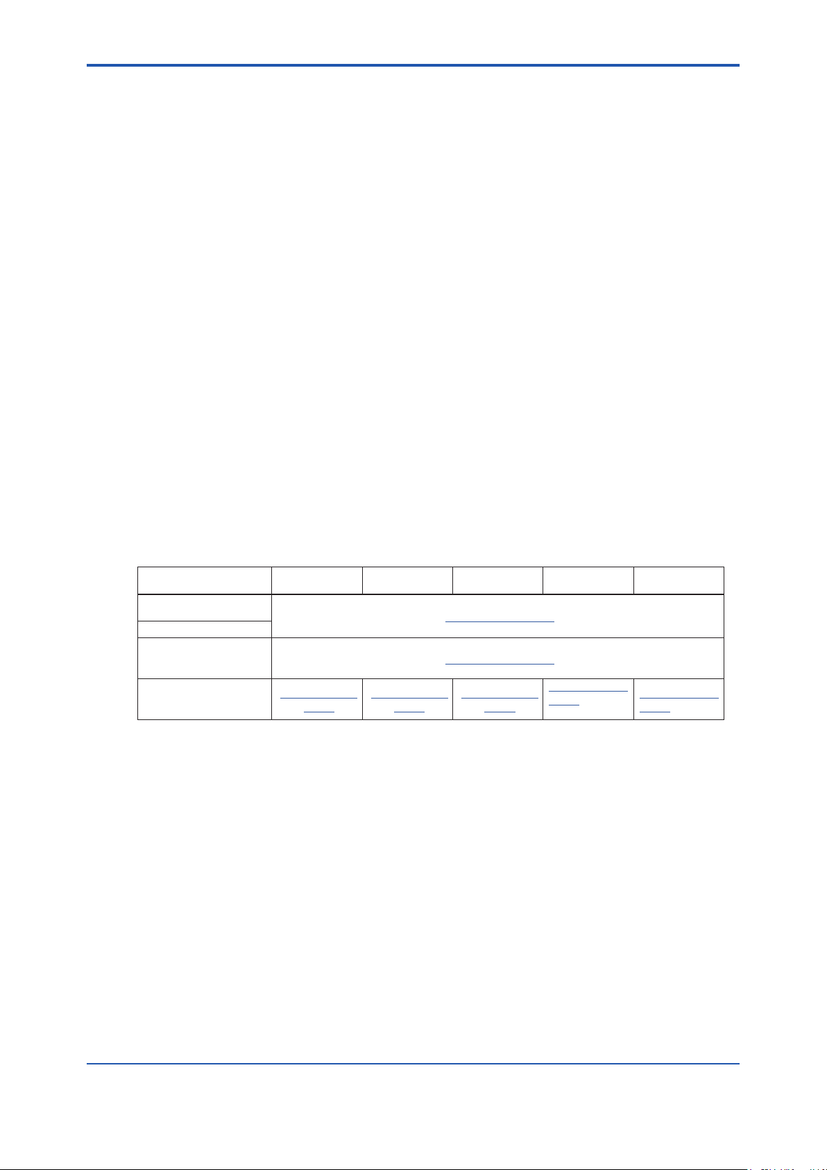
This manual describes the operation (equipment setting, calibration) as a PH converter. For the
parts common to the converter, refer to the other related documents that are separated as shown
in the table below.
Contents FC800D RC800D TB820D pH
Introduction and
general description
Wiring and installation
Converter operation
(Setting, Maintenance,
Troubleshooting)
Sensor operation
(Setting, Calibration)
IM 12F05B10-
02EN
IM 12F04B10-
02EN
IM 12A01G01-02EN
IM 12A01G01-03EN
IM 12E01B30-
02EN
IM 12A01G0201EN (This
manual)
ii
Conductivity
(SC)
IM 12A01G0301EN
n Trademark Notices
• FLEXA, FLXA, SENCOM are trademarks or registered trademarks of Yokogawa Electric
Corporation.
• All other company and product names mentioned in this user’s manual are trademarks or
registered trademarks of their respective companies.
• We do not use TM or ® mark to indicate those trademarks or registered trademarks in this
user’s manual.
n Terminology
sensor(s): sensor, sensor unit, sensor module, SA11 + sensor
SENCOM SA: SA11 SENCOM Smart Adapter or 1st (2nd) input “-CL” (SENCOM SA for
Chlorine ) or “-TB (SENCOM SA for Turbidity)”
analog sensor (module) selectable sensors when “-P1”, “-C1” is specied for 2nd input.
sensor connection number. : identifies connected sensors to 1st or 2nd input. 1-1 refers to
e.g. PH8E□P, PH4□, SC4AJ, SC210G
sensor connected for 1st input. 2-1 refers to sensor connected
for 2nd input.
IM 12A01G02-01EN 1st Edition : Mar. 25, 2021-00
Page 4

FLXA402T
Liquid Analyzer for Turbidity and Chlorine
Operation of pH
IM 12A01G02-01EN 1st Edition
CONTENTS
u Introduction ....................................................................................................i
1. Sensor Menu Outline ............................................................................... 1-1
2 Sensor menu ............................................................................................. 2-1
2.1 Detail ................................................................................................................... 2-1
2.2 Calibration ......................................................................................................... 2-6
2.3 Reset wellness ..................................................................................................2-6
2.4 Initialization ....................................................................................................... 2-7
2.5 Sensor settings ................................................................................................. 2-7
3. Sensor setting ........................................................................................... 3-1
3.1 Congure sensor ..............................................................................................3-1
3.1.1 Temperature settings ......................................................................... 3-1
3.1.2 Others ................................................................................................ 3-1
3.2 Measure setting ................................................................................................. 3-2
3.2.1 Temperature settings ......................................................................... 3-2
3.2.2 Temp compensation ........................................................................... 3-2
3.2.3 pH ....................................................................................................... 3-3
3.2.4 High/Low alarm setting ...................................................................... 3-3
3.3 Calibration settings ..........................................................................................3-4
3.3.1 Cal. set pH.......................................................................................... 3-4
3.3.2 Cal. Set others ................................................................................... 3-5
3.3.3 Cal. set temperature .......................................................................... 3-5
3.4 Wellness settings .............................................................................................. 3-6
3.4.1 Impedance settings ............................................................................ 3-6
3.4.2 Progress time ..................................................................................... 3-7
3.4.3 Dene SENCOM status ..................................................................... 3-7
4. Calibration pH ........................................................................................... 4-1
4.1 pH Calibration .................................................................................................... 4-2
4.1.1 pH Manual .......................................................................................... 4-2
4.1.2 Automatic Calibration ......................................................................... 4-2
4.2 Temperature calibration ..................................................................................4-3
Appendix References ............................................................................ App.-1
Revision Record .......................................................................................................i
Toc-1
IM 12A01G02-01EN 1st Edition : Mar. 25, 2021-00
Page 5

Blank Page
Page 6
<1. Sensor Menu Outline>
1. Sensor Menu Outline
Main/Home screen > “Sensor menu”. > “Detail” / “Calibration” / “Setting”
The operation is secured by password. See the section 5.4 in IM 12A01G01-03EN Operation of
Converter.
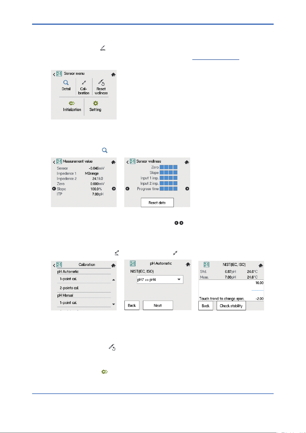
Figure 1.1 Sensor menu
n Details
On Sensor menu, tap “Detail”. Read 2.1.
1-1
Figure 1.2 Sample image of Sensor details
On Sensor details screen, sensor status is displayed. turns the page to show the sensor
status, maintenance information, PH module information or logbook.
n Calibration
On Home/Main screen, tap . On Sensor menu, tap for calibration of sensors.
Figure 1.3 Sample images of pH Calibration
For further information on sensor calibration, read chapter 4.
n Reset wellness
Go to Sensor menu> tap . Read 2.3 Reset wellness
n Initialization
On Sensor menu, tap . Read 2.4 Initialization.
IM 12A01G02-01EN 1st Edition : Mar. 25, 2021-00
Page 7

<1. Sensor Menu Outline>
n Congure sensor
Converter menu or Sensor menu > “Setting”
Go to Converter menu to congure the setting of converter such as mA output, display setting.
Go to Sensor menu to congure the sensor setting such as calibration setting.
Figure 1.4 Left; before conguration Right; after conguration
When you change parameter, the changed parameter becomes highlighted. To save and
overwrite the data, tap
Read 3. Sensor setting about sensor conguration.
1-2
IM 12A01G02-01EN 1st Edition : Mar. 25, 2021-00
Page 8
<2. Sensor menu>
2 Sensor menu
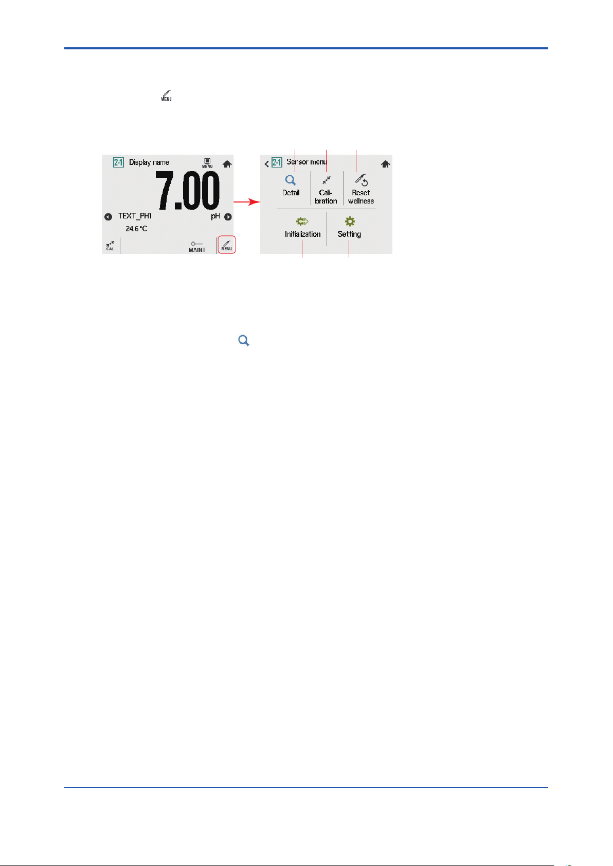
Main screen > Sensor menu
The following operation are available.
Detail (details on sensors), Calibration (sensor calibration), Setting (sensor setting), etc.
2.1 2.2 2.3
2.52.4
Figure 2.1 Sensor menu
2.1 Detail
Go to Sensor menu > “Detail” to check details (setup, sensor wellness, calibration, and module
production number).
In case of trouble, when you contact Yokogawa service, please inform us of the module and
FLXA402T software revision displayed on the Detail and module production number, revision
number indicated on the nameplate attached to the instrument.
2-1
IM 12A01G02-01EN 1st Edition : Mar. 25, 2021-00
Page 9
<2. Sensor menu>
*2
*1
2-2
*1: “----”is displayed, depending on a calibration or sensor conguration that a user implements.
*2: The number of log page goes as many as the connected sensors.
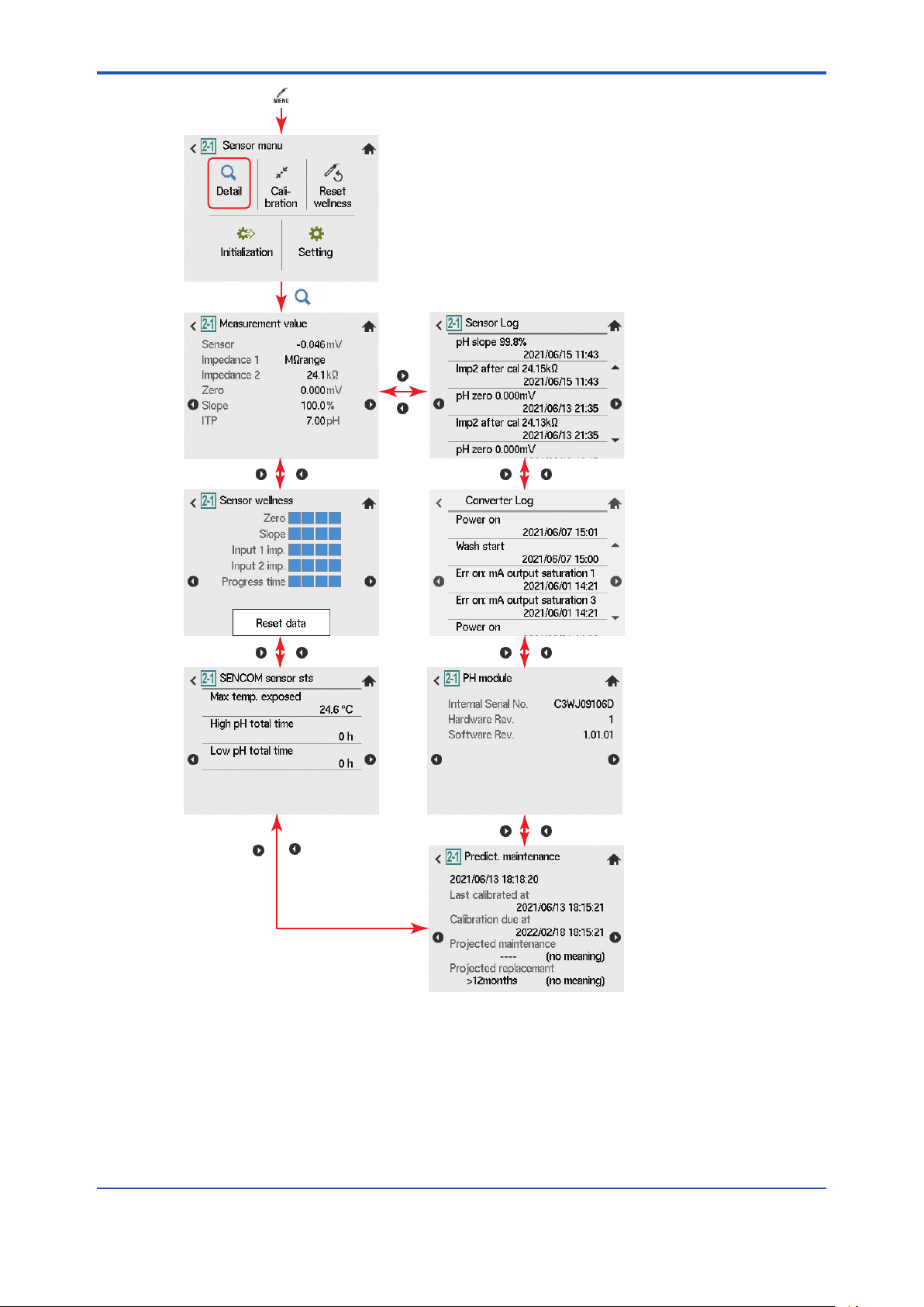
Figure 2.2 Sensor menu ow chart
IM 12A01G02-01EN 1st Edition : Mar. 25, 2021-00
Page 10

<2. Sensor menu>
n Measurement value
l Sensor
Represents the measured electromotive force of sensor.
l Impedance 1
For a PH sensor, “Impedance” shows electrical resistance of the glass electrode. The FLXA402T
checks the impedance to know damage of the electrode.
In case of “Input Impedance setting” is “High” and the measured input-1 impedance value is
higher than 100 kΩ, the display shows “MΩ RANGE”. If the measured input-1 impedance value
is lower than 100 kΩ, the display shows “BAD”. If impedance is set to “Low”, the measured
impedance value is displayed.
If Impedance measurement(A) is set to “Disabled”, “----”is displayed. You can change the setting
of Impedance measurement (A) only when PH sensor module is in use.
l Impedance 2
Impedance shows the electrical resistance of the reference electrode liquid junction. The liquid
junction forms the electrolytic contact between the reference electrode and the measuring
electrode. Therefore, it must be kept clean and lled with conductive electrolyte. Otherwise the
measurement will suer from instability, drift and measuring errors.
In case of “Input Impedance setting” is “High” and the measured impedance 2 value is higher
than 100 kΩ, the display shows “MΩ RANGE”. The measured impedance 2 value is lower than
100 kΩ, display shows “BAD”. If Impedance is set to “Low”, the measured impedance value is
displayed.
If Impedance measurement(A) is set to “Disabled”, “----”is displayed. See 3.4.1 Impedance
settings for the details.
2-3
l Zero
Theoretically, pH_Zero is 0 mV in a buer solution of pH 7. The ZERO value indicates the
condition of the sensor. The trend of ZERO drift of the sensor is used to predict the lifetime of the
sensor.
ZERO can also be displayed in pH units and then it represents the pH value where the sensor
output is 0 mV at 25ºC.
To set directly, go to Sensor menu> “Measure setting”> “Calibration setting”> “Zero/Slope/ITP”>
“Zero”. Read 3.3.1 for the details.
l Slope
Slope indicates the sensor sensitivity. It is expressed as % of the theoretical value of the
electromotive force characteristics of the sensor
The theoretical value of the electromotive force characteristic (100% slope) is 59.16 mV / pH
(at 25° C) according to the NERNST equation. The slope can only be calibrated by two-point
calibration using two pH solutions. A low slope indicates that the sensor is not clean or it indicates
a bad sensor.
The SLOPE can also be displayed as mV/pH value at 25 ºC if the user has dened this variable
as mV/pH in user setting.
To set directly, go to Sensor menu> “Measure setting”> “Calibration setting”> “Zero/Slope/ITP”>
“Slope”. Read 3.3.1 for the details.
IM 12A01G02-01EN 1st Edition : Mar. 25, 2021-00
Page 11

<2. Sensor menu>
+mV
Theoretical value
pH7, 0mV
2-4
pH0
Figure 2.3 Zero/Slope
l ITP
ITP represents a pH value where the electromotive force of the sensor does not change with
temperature.
n Sensor wellness
Sensor wellness shows the soundness of a sensor. The larger number of n appears in each
gauge, the sounder the parameter concerned is. A gauge is indicated for only those parameters
whose sensor wellness setting is “enabled, “while a bar (----) is displayed if the sensor wellness
setting is “disabled.”
When analog sensor module is in use, if Impedance measurement (A) is set to “Disabled”, “----”is
displayed, even if Impedance wellness is “Enabled”.
For Sensor wellness, go to Sensor menu > Congure sensor > Wellness settings
See 3.4 for the details.
When a sensor or an electrode is exchanged or replaced, sensor wellness data should be reset.
Use Reset wellness in Sensor menu. See 2.3 Reset wellness
-mV
pH14
Zero
actual value
(pH_Slope is the slope of the line)
n SENCOM Sensor status
The status of the sensor is displayed.
l Max temp. exposed
Displays the maximum temperature, which is automatically updated every time a higher
temperature is measured.
l High pH total time/Low pH total time
Displays the total time during which the pH value remains above the upper pH limit or below the
lower pH limit.
Up to 10 years (87600 hours) can be counted, after which the time is no longer updated.
To set the parameters of High/Low pH value, go to Sensor menu > Congure sensor > Wellness
settings > Dene Sencom status
n Predict. maintenance
l Last calibrated at
Date on which the last sensor calibration was performed. The displayed value of the Zero is the
result of this calibration. The displayed value of Slope was calibrated on this date only if the last
calibration was a 2-point calibration.
IM 12A01G02-01EN 1st Edition : Mar. 25, 2021-00
Page 12

<2. Sensor menu>
l Calibration due at
Date when the calibration must be done next according to the settings of the calibration interval.
To set the calibration intervals, go to Sensor menu > Calibration settings > Limits and timing
>Calib. interval
l Projected maintenance
The projected maintenance function predicts the date when the sensor unit will need recalibrating
for maintaining measurement accuracy. The function checks the input-2 impedance (reference
impedance) every 24 hours.
The function predicts the date when the input-2 impedance will cross the upper or lower limits,
and indicates the date and its status (the status is displayed in parentheses).
As shown in the gure below, the date is predicted based on the intersection point of the upper or
lower limits and the extrapolated line of the values obtained by the least squares method.
Upper limit
Value
Lower limit
Impedance 2
2-5
Current
date
Figure 2.5 Projected maintenance
Projected
maintenance date
Day
The status shows the certainty of the projected maintenance date in terms of the correlation
coecient R. Table 2.1, Table 2.2 shows pattern of the projected maintenance date, status.
Table 2.1 Display pattern of the projected maintenance date
Projected
date
- - : not predictable due to insucient data
Table Display pattern of the status
Status (- - - - -) (Poor) Reasonable) (Excellent)
Criteria (R < 0.50) (0.50 ≤ R < 0.70) (0.70 ≤ R < 0.85) (0.85 ≤ R < 1.00)
---- 0-1 month 1-3 months 3-6 months 6-12 months Over 1 year
l Projected replacement
The projected replacement function predicts the date when the sensor will need replacing for
maintaining the measurement accuracy, based on the pH zero and pH slope on each calibration,
and Impedance 2 after each calibration. The projected replacement date is predicted based
on these parameters stored upon calibration, and displayed the same as that of projected
maintenance. For details, see the description about the projected maintenance. Since three
parameters (pH zero, pH slope, and Impedance 2 after calibration) are used for this projection,
the nearest coming day is selected as the projected replacement date from the extrapolated line
of the values obtained by the least squares method.
n PH module
This screen enables operators to check the module Serial No., Hardware Rev, Software Rev.
n Converter log, Sensor log
Same display as on the converter “Detail”.
See 3.1 in IM 12A01G01-03EN Operation of Converter.
IM 12A01G02-01EN 1st Edition : Mar. 25, 2021-00
Page 13

<2. Sensor menu>
2.2 Calibration
Sensor menu > Calibration . See Chapter 4.
Figure 2.6 Calibration selection
If you have a password, a prompt dialog box appears to input your password. After the password
is veried, the page shifts to Calibration.
For password, see 5.4 in IM 12A01G01-03EN Operation of Converter.
2.3 Reset wellness
Sensor menu > Reset wellness
A dialog box appears to ask if you want to reset sensor wellness data.
Yes: the wellness is reset
No: the reset will not take place. The page returns to Sensor menu.
2-6
Figure 2.7 Reset wellness and dialog
If you created a password, a prompt dialog box appears to input your password. After the
password is veried, a dialog appears to conrm if you want to reset.
For password, see 5.4 in IM 12A01G01-03EN Operation of Converter.
IM 12A01G02-01EN 1st Edition : Mar. 25, 2021-00
Page 14

<2. Sensor menu>
2.4 Initialization
Sensor menu > Initialization
The screen jumps to Load PH cong. File, where you can initialize parameters of analog sensor
module.
When Wash is in progress, text on the screen is grayed out and you cannot go to sensor
Initialization screen even if you tap the icon.
Figure 2.8 Initialization in sensor menu
In the box of File name, name of dened sensor cong. le to load is displayed, after sensors
connected are automatically detected. You cannot change the le name.
If you tap “Execute”, the loading starts. When the loading ends, you will return to Sensor menu.
If you create a password, a prompt dialog box appears to enter the password. After the password
is veried, Sensor initialization screen appears.
For password, see 5.4 in IM 12A01G01-03EN Operation of Converter.
If you go to Sensor initialization screen, maintenance contact becomes ON, and the other contact
outputs keep the current status. When automatic HOLD function is enabled, mA output becomes
HOLD.
2-7
2.5 Sensor settings
Sensor menu > Setting > Sensor setting
When Wash is in progress, text on the screen is grayed out. You cannot move to Sensor settings
even if you tap the icon.
For further information on sensor settings, read chapter 3.
Figure 2.9 To Sensor setting
If you create a password, a prompt dialog box appears to enter the password. After the password
is veried, Sensor setting is displayed.
For password, see 5.4 in IM 12A01G01-03EN Operation of Converter.
If you go to Sensor setting, the maintenance contact becomes ON, and the other contact outputs
keep the current status. When automatic HOLD function is enabled, mA output becomes HOLD.
IM 12A01G02-01EN 1st Edition : Mar. 25, 2021-00
Page 15

Blank Page
Page 16

<3. Sensor setting>
3. Sensor setting
When you congure each setting, ll in User setting table we provide, and keep it in safe place.
Download the user setting table from our website below.
http://www.yokogawa.com/an/xa402t/download/
To congure sensor setting, go to
Main screen “Menu” > Sensor menu > “Setting” > Sensor setting
In Sensor setting, maintenance contact turns ON and other contact output keeps the current
status. When auto HOLD function is enabled, mA output becomes HOLD status.
3-1
Figure 3.1 Sensor menu to Sensor setting
To know how to conrm or edit the settings with parameters, refer to IM 12A01G01-03EN
Operation of Converter.
In the parameter list of Sensor setting, parameters with (A) or (S) represent that (A) is exclusive
for Analog sensor module, and (S) is exclusive for SENCOM SA. You cannot congure
parameters which do not apply to the sensors to be used.
When you congure sensor setting and save the data, a dialog box appears to notify the
operation is in progress. If you succeed the conguration, you will return to the setting menu, and
if fail, a fail dialog appears.
3.1 Congure sensor
Congure the setting of sensors which connects to FLXA402T.
3.1.1 Temperature settings
n Temp. element (A)
Select the temperature element used for compensation from among Pt1000, Pt100, 3kBalco,
8k55, PTC10k, 6k8, and 500Ω. Select the same type of temperature element as is actually
connected.
3.1.2 Others
n MODBUS address (S)
Don’t change.
IM 12A01G02-01EN 1st Edition : Mar. 25, 2021-00
Page 17

<3. Sensor setting>
3.2 Measure setting
Set parameters for measurement.
3.2.1 Temperature settings
n Unit
Displays the unit for temperature, but you cannot change the setting here.
To change the setting, go to
Converter menu > Setting> Advanced setting > Other
3.2.2 Temp compensation
n Compensation
This section describes the setup of the temperature compensation function that compensates
temperature properties of the electromotive force of the pH sensor.
Methods: Automatic, Manual, External input
Automatic: when a temperature element is used,
Manual: when a manually set temperature is used.
External input: when mA input to the converter is used. Go to
Converter menu > Converter setting > mA input setting (Ad) >
Temperature
The setting must be matched to the specication of the device to use as
an external input.
3-2
NOTE
When Manual is selected on the Temperature compensation, the process temperature shall be
entered in the “Manual temp.” Home/Main screen displays the temperature you set.
n Manual temp.
When you select Manual, you must enter process temperature to Manual temp.
n Reference temp.
Set a reference temperature by/to which the measured pH value must be converted. Normally
25°C is used, so this temperature is chosen as the default value.
NOTE
Reference temperature here is used by the method “TC” on 2.2.3 Method (pH).
IM 12A01G02-01EN 1st Edition : Mar. 25, 2021-00
Page 18

<3. Sensor setting>
3.2.3 pH
n Method (pH)
Select a temperature conversion method for pH measurement. “None” does not perform the
temperature conversion.
Choose process temperature compensation from among “None”, “TC”.
n Temp. coef
l Temp. coef (TC pH)
This linear temperature coecient is used for the conversion to a reference liquid temperature. It
is possible to enter the temperature coecient (TC) factor directly. If the temperature coecient
factor of the sample liquid is known from laboratory experiments or has been previously
determined, it can be entered here.
This TC is a pH variation per °C (ΔpH/ΔT). Adjust the value between -0.1 to 0.1 pH/ºC. In
combination with the Reference temp. setting, a linear compensation function is available, which
is suitable for specic chemical solutions.
3.2.4 High/Low alarm setting
3-3
Alarms from sensors are sorted out to “Device fail”, “Device status”, “Measure alarm”, “Sensor
status”. High/Low alarm setting denes High/low alarm limits of measurement values.
For details on alarms, see 4.7 in IM 12A01G01-03EN Operation of converter.
Parameter Alarm description Setting range Default
Temp. warning high limit Temperature too high -30.0~140.0[˚C] 140.0[˚C]
Temp. warning low limit Temperature too low -30.0~140.0[˚C] -30.0[˚C]
pH warning high limit pH too high -2.0~16.0[pH] 16.00[pH]
pH warning low limit pH too low -2.0~16.0[pH] -2.00[pH]
IM 12A01G02-01EN 1st Edition : Mar. 25, 2021-00
Page 19

<3. Sensor setting>
3.3 Calibration settings
3.3.1 Cal. set pH
The screen ow diers depending on the combination of objects to be measured.
Calibration parameters for a pH converter involve slope (sensitivity), zero (Asymmetry
potential), and ITP (isothermal point). Figure 3.2 shows the relations between pH value and the
electromotive force of the sensor element.
The characteristic of the electromotive force in pH measurement is represented by an oset
also known as Asymmetry potential [mV] or zero [pH] and a Slope [%, mV/pH]. For an ideal
sensor, the theoretical slope is 59.16 mV/pH at 25ºC. The slope can be entered in mV/pH or as a
percentage of the theoretical slope (100% corresponds to 59.16 mV/pH).
ITP represents a pH value where the electromotive force of the element does not change with
temperature. Note that slope and zero are dened at 25ºC.
3-4
500
mV
Asymmetry potential
0
0 mV
- 200
0
Figure 3.2 Calibration parameter
n Unit
l Zero unit/Slope unit
Zero is Asymmetry Potential. The method of zero (Asymmetry potential) unit conforms to the DIN
standard for IEC 60746-2 instruments. Zero is dened in pH or mV.
The unit of Slope (sensitivity) is mV/pH or % (with the theoretical value as 100%).
ΔpH
ΔmV
ITP (Isothermal point)
7
ITP
Zero
pH
0 °C
10 °C
25 °C
14
n Limits and timing
l Zero high / low limit
Set the high and low limits of Zero (Asymmetry potential). During calibration, it is checked
whether the new zero exceeds these high and low limits. Narrowing the band will prevent bad
calibration procedures and calibration of bad sensors, which results in higher accuracy. The
default values should be adjusted to suit the application and the “users” criterion.
l Slope high/low limit
Set the high and low limits of Slope (sensitivity). During calibration, it is checked whether the
new slope exceeds these high and low limits. Narrowing the band will prevent bad calibration
procedures and calibration of bad sensors, which results in higher accuracy. The default values
should be adjusted to suit the application and the “users” criterion.
IM 12A01G02-01EN 1st Edition : Mar. 25, 2021-00
Page 20

<3. Sensor setting>
n Buers (select set)
l Buers (select set)
Select a standard for calibration. Select one from “NIST (IEC,ISO)”, “DIN(DE)”, “US”. Yokogawa
recommend “NIST (IEC, ISO, JIS equivalent)” standard buer. Refer to Appendix for standard
buers.
n Zero/Slope/ITP
You can enter Zero (Asymmetry potential), Slope (sensitivity), and ITP values directly in the
screen displayed.
NOTE
It is not always necessary to enter this data. In most cases, the FLXA402T automatically does
this while performing calibration. Direct input is used when special electrode systems are used or
when the calibration in the process environment is not possible.
3.3.2 Cal. Set others
Set the parameters (stability width and stabilization time) used for the stability check during
calibration and the calibration cycle used for updating the next date and time displayed on the
sensor details screen.
3-5
l Step range (pH)
Set the range over which the stability of a measured value is checked. If variations of a measured
value over the stabilization time are within this range, the measured value is judged to have
stabilized.
l Stabilization time
During calibration, the stability of the measured value is constantly monitored. When variations of
the measured value are within a value set in Step Range for a longer time than this stabilization
time set here, the value is regarded as being stable. If the measured value does not stabilize
within 10 minutes, calibration is aborted.
l Calibr. interval
Set the interval in which a new calibration must be conducted. If the interval set here is exceeded,
the instrument will be notied according to the setting in “Calib. time exceeded” in the error
conguration.
3.3.3 Cal. set temperature
l Temp.oset
You can enter directly Temp. oset value here.
Input the temperature-corrected oset value based on the next equation.
Temp.oset = actual value - (displayed temperature value- current temperature oset)
• Check actual value on other devices.
• Displayed temperature value is displayed on FLXA402T process measuring normally.
• Current temperature oset is conrmed on Temp. oset screen.
NOTE
Use this function when a calibration is disabled.
You don’t need to input directly Temp. oset when temp. oset is revised by calibration.
IM 12A01G02-01EN 1st Edition : Mar. 25, 2021-00
Page 21

<3. Sensor setting>
3.4 Wellness settings
This screen is used to set items relating to sensor diagnostics displayed on the sensor detail
screen. Gauges are displayed for only parameters that have been enabled in Wellness settings.
Parameters set to Disable are indicated with a bar “----”.
Figure 3.3 Sensor wellness
The setting parameters include “Impedance settings” “Impedance 1”, “Impedance 2”, “Progress
Time”.
3.4.1 Impedance settings
This screen is used to set the impedance relating to an input impedance check. The setting
aects the diagnostic screen on the sensor details screen and Impedance errors.
3-6
l Impedance measure (A)
Set Impedance measure to “Enabled” or “Disabled”.
This setting is related to the Impedance display on the sensor details screen, the sensor wellness
gauge on the sensor diagnostic screen, and the Impedance error. When enabled, the pH sensor
impedance measurement can be performed, checked, and monitored. When set to “Disabled”,
the impedance measurement is not performed. The Impedance item on the sensor details screen
and sensor wellness will be displayed as a bar “----”.
n Impedance 1, Impedance 2
l Impedance 1, 2 (High, Low)
• When the setup value is “High”
When the measured value of Impedance1 on the sensor details screen is 100 k Ω or more,
“M Ω RANGE” is displayed, and when it is smaller than 100 k Ω, “BAD” is displayed.
In the sensor wellness screen and Impedance error, the diagnostic criteria are determined
by the worst value of 100 kΩ and the setting value of [Best value limit].
• When the set value is “Low”
The measured impedance value is displayed on the sensor details screen.
On the sensor diagnostic screen and Impedance error, the upper / lower limit settings are
the diagnostic criteria.
l Impedance high limit, Impedance low limit, FINE
You can change the limit value of the diagnostic criteria, which is used according to the setting of
Impedance 1,2 High/Low.
IM 12A01G02-01EN 1st Edition : Mar. 25, 2021-00
Page 22

<3. Sensor setting>
l Impedance 1,2 (Enabled/Disabled)
You can set whether to display Impedance 1 and Impedance 2 on sensor wellness screen for
each sensor.
[Precautions regarding settings]
Impedance 1 measures the pH glass lm resistance, and Impedance 2 measures the resistance
of the liquid junction of the reference electrode.
Impedance can only be measured with a sensor that has a liquid earth electrode. The liquid earth
electrode is a metal electrode other than the glass electrode and the reference electrode that
comes into contact with the measurement liquid and transmits the potential of the liquid to the
measurement circuit. When using a sensor that does not have a liquid earth electrode, disable
Impedance measurement (A).
Sensors with liquid earth electrode: PH8EFP, PH8ERP, etc.
Sensors without liquid earth electrode: PH4P, PH4PT, PH4C, PH4CT, PH4F, etc.
When pH is measured with water with extremely low conductivity, the impedance of the
sample itself is high. In this case, in the “Error setting” of the converter setting of FLXA402T, set
“Impedance 2 too high” to “O”.
[Errors in Impedance1, Impedance2]
You can set the presence or absence of diagnosis and diagnostic criteria in this item, but you
have to set whether or not to issue an Impedance error in the converter setting. Refer to the
FLXA402T Operation of Converter IM 12A01G01-03EN for the setting.
3-7
3.4.2 Progress time
Set Progress time to enabled / disabled to be used on the sensor wellness screen. If it is
disabled, a bar will be displayed. The time limit value is the reference value of the diagnostic
gauge when the Progress time setting is enabled.
■ decreases as the operating time of the converter increases, and becomes zero when the usage
limit value is reached.
3.4.3 Dene SENCOM status
Congure settings related to status of sensors which are displayed on sensor detail screen.
Figure 3.4 Sensor status
The setting parameters include “Low pH total time”, “High pH total time”. For each meaning of
sensor status, see 2.1 Detail.
IM 12A01G02-01EN 1st Edition : Mar. 25, 2021-00
Page 23

Blank Page
Page 24

<4. Calibration pH>
4. Calibration pH
Before pH measurement, calibrate the pH sensor with the standard solution.
Figure 4.1 Sensor menu to Calibration
Go to Calibration as shown in Figure 4.1. You can go to Calibration by tapping on Home or
Main screen.
The calibration items include “pH” and “Temperature”.
The item to be calibrated is determined according to the settings made in the Congure sensor >
Sensor type (A).
Calibration of “pH” with the measured value and its stability can be monitored on the calibration
trend, thereby variation and stability can be checked graphically.
4-1
Figure 4.2 Sample of Calibration trend (manual calibration 1-point)
If FLXA402T detects any sensor fault, calibration cannot be conducted.
NOTE
Note the following when performing calibration with buer solutions.
• Before starting a calibration, make sure the electrode system is properly cleaned and the
electrodes are fully functional. They must be rinsed with clean water to avoid contamination
of the calibration solution(s).
• Always use fresh buer solution to avoid the risk of introducing errors from contaminated or
old solutions. Buers supplied as liquids have a limited shelf life, especially alkaline buers,
which absorb CO2 from the air.
• Yokogawa recommends NIST(IEC,ISO) buer standards for the best accuracy and buer
capacity.
• Always ensure that the sensors are properly conditioned, clean and lled with the correct
electrolyte solution (if appropriate) before starting a calibration. Refer to the sensor
instructions for details.
IM 12A01G02-01EN 1st Edition : Mar. 25, 2021-00
Page 25

<4. Calibration pH>
4.1 pH Calibration
There are “pH Manual”, “pH Auto”.
4.1.1 pH Manual
The measured value is adjusted to match the value of the buer standards or a process solution
with a known pH value (buer solution).
Check pH value, temperature inuence, and stability in advance and enter the calibration known
value manually.
Select the calibration type from among [zero (1pt)], [zero/slope (2pt)].
Follow the prompts displayed on the screen. A stability check is conducted at each measurement
point. Proceed to the next step only after the reading has stabilized.
At calibration, we advise leaving the sensors in the buer solution for three to ve minutes before
proceeding to the check stability even when the reading has stabilized. This will give you reliable
and accurate calibration results.
NOTE
When a sensor or an electrode is replaced, sensor wellness data should be reset.
4-2
l Zero (1 pt)
This calibration is one-point calibration. Zero of the calibration parameter is updated.
l Zero/slope (2 pts)
This calibration is two-point calibration with using two types of solution.
Zero and slope of calibration parameter are updated.
4.1.2 Automatic Calibration
In Automatic Calibration menu, when a standard solution is selected, a calibration value
according to the temperature is entered automatically. You can set the selectable standard
solution in [Buers (select set)] > Select Buer.
“NIST (IEC, ISO) is recommended. Refer to Table 1 in Appendix to know the temperature and pH
value of each solution.
In the same way as manual pH calibration, select the calibration type [Zero (1 pt)] or [zero/slope
(2 pts)].
Follow the prompts displayed on the screen.
A stability check is conducted at each measurement point. Proceed to the next step only after the
reading has stabilized.
When calibrating, even if a sensor is immersed in a buer solution and the indicated value
stabilizes, leave it as it is for 3 to 5 minutes before proceeding to the stability check to obtain an
accurate and reliable result.
NOTE
When a sensor or an electrode is replaced, sensor wellness data should be reset.
l Zero (1 pt)
Select one type of solution. Zero of the calibration parameter is updated.
IM 12A01G02-01EN 1st Edition : Mar. 25, 2021-00
Page 26

<4. Calibration pH>
l Zero/slope (2 pts)
Specify two standard solutions with dierent pH each other. Select a sequence and the type of
standard solution from the list shown in Table 4.1 Zero and slope of the calibration parameter are
updated
Table 4.1 Automatic calibration menu
Buer settings Calibration point Buer, sequence menus
NIST/DIN19266 1 pH7
pH4
pH9
2 pH7>>pH4
pH7>>pH9
pH4>>pH7
pH9>>pH7
pH4>>pH9
DIN (DE) 1 pH6.8
pH4.7
pH9.2
2 pH6.8>>pH4.7
pH6.8>>pH9.2
pH4.7>>pH6.8
pH9.2>>pH6.8
pH4.7>>pH9.2
US 1 pH7
pH4
pH10
2 pH7>>pH4
pH7>>pH10
pH4>>pH7
pH10>>pH7
pH4>>pH10
4-3
4.2 Temperature calibration
To provide accurate measurement, temperature measurement is critical. Temperature calibration
is performed when the temperature is measured with a high-precision thermometer and the
temperature reading of the output device is adjusted. To improve the calibration accuracy,
perform temperature calibration at a temperature as close as possible to the normal operating
temperature.
IM 12A01G02-01EN 1st Edition : Mar. 25, 2021-00
Page 27

Blank Page
Page 28

<Appendix References>
Appendix References
n Buer tables
The following tables show the details of the buer solutions selectable in Calibration settings of
pH (Section 4.1 pH Calibration) (unit: pH).
Table 1 NIST (IEC, ISO)
0°C 5°C 10°C 15°C 20°C 25°C 30°C 35°C 38°C 40°C 45°C 50°C 55°C 60°C 70°C 80°C 90°C 95°C
1.68 pH
4.01 pH
6.87 pH
9.18 pH
Table 2 DIN (DE) (German buers) so called: technical buer solutions
4.65 pH DIN
6.79 pH DIN
9.23 pH DIN
Table 3 US technical buers
4.0 pH US
7.0 pH US
10.0 pH US
1.668 1.670 1.672 1.675 1.679 1.683 1.688 1.691 1.694 1.700 1.707 1.715 1.723 1.743 1.766 1.792 1.806
4.003 3.999 3.998 3.999 4.002 4.008 4.015 4.024 4.030 4.035 4.047 4.060 4.075 4.091 4.126 4.164 4.205 4.227
6.984 6.951 6.923 6.900 6.881 6.865 6.853 6.844 6.840 6.838 6.834 6.833 6.834 6.836 6.845 6.859 6.877 6.886
9.464 9.395 9.332 9.276 9.225 9.180 9.139 9.102 9.081 9.068 9.038 9.011 8.985 8.962 8.921 8.885 8.850 8.833
0°C 10°C 20°C 25°C 30°C 40°C 50°C 60°C 70°C 80°C 90°C
4.670 4.660 4.650 4.650 4.650 4.660 4.680 4.700 4.720 4.750 4.790
6.890 6.840 6.800 6.790 6.780 6.760 6.760 6.760 6.760 6.780 6.800
9.480 9.370 9.270 9.230 9.180 9.090 9.000 8.920 8.880 8.850 8.820
0°C 5°C 10°C 15°C 20°C 25°C 30°C 35°C 40°C 45°C 50°C 55°C 60°C
4.000 3.998 3.997 3.998 4.001 4.005 4.001 4.018 4.027 4.038 4.050 4.064 4.080
7.120 7.090 7.060 7.040 7.020 7.000 6.990 6.980 6.988 6.978 6.970 6.890 6.980
10.317
10.245 10.179
10.118
10.062 10.012
9.966
9.926 9.889
9.856 9.828
9.828
App.-1
9.828
NOTE
Yokogawa recommend the use of NIST (primary buer standards). NIST is an approved standard
solution with the best buer capacity (the ability to resist pH change with contamination).
IM 12A01G02-01EN 1st Edition : Mar. 25, 2021-00
Page 29

Blank Page
Page 30

Revision Record
l Manual Title : FLXA402T Liquid Analyzer for Turbidity and Chlorine Operation of pH
l Manual No. : IM 12A01G02-01EN
Mar. 2021/1st Edition
Newly published
i
Yokogawa Electric Corporation
2-9-32 Nakacho, Musashino-shi, Tokyo 180-8750, JAPAN
http://www.yokogawa.com/
IM 12A01G02-01EN 1st Edition : Mar. 25, 2021-00
Page 31

Blank Page
 Loading...